JP2020172076A - Method for manufacturing seat pad, seat pad, and three-dimensional modelling data - Google Patents

Method for manufacturing seat pad, seat pad, and three-dimensional modelling data Download PDF

Info

Publication number
JP2020172076A
JP2020172076A JP2019076046A JP2019076046A JP2020172076A JP 2020172076 A JP2020172076 A JP 2020172076A JP 2019076046 A JP2019076046 A JP 2019076046A JP 2019076046 A JP2019076046 A JP 2019076046A JP 2020172076 A JP2020172076 A JP 2020172076A
Authority
JP
Japan
Prior art keywords
seat pad
pad
bone
skeleton
porous structure
Prior art date
Legal status (The legal status is an assumption and is not a legal conclusion. Google has not performed a legal analysis and makes no representation as to the accuracy of the status listed.)
Pending
Application number
JP2019076046A
Other languages
Japanese (ja)
Inventor
大一 板橋
Daiichi Itabashi
大一 板橋
真樹 出野上
Masaki Denokami
真樹 出野上
Current Assignee (The listed assignees may be inaccurate. Google has not performed a legal analysis and makes no representation or warranty as to the accuracy of the list.)
Bridgestone Corp
Original Assignee
Bridgestone Corp
Priority date (The priority date is an assumption and is not a legal conclusion. Google has not performed a legal analysis and makes no representation as to the accuracy of the date listed.)
Filing date
Publication date
Application filed by Bridgestone Corp filed Critical Bridgestone Corp
Priority to JP2019076046A priority Critical patent/JP2020172076A/en
Publication of JP2020172076A publication Critical patent/JP2020172076A/en
Pending legal-status Critical Current

Links

Images

Abstract

To provide a method for manufacturing a seat pad capable of easily manufacturing the seat pad having a fluid passage, the seat pad, and three-dimensional modeling data.SOLUTION: A method for manufacturing a seat pad manufactures a seat pad 302 composed of a porous structure 1, and includes a modelling step for modelling the seat pad using a three-dimensional printer. The porous structure is composed of a flexible resin or rubber. The seat pad has a fluid passage 5 for allowing a fluid to pass from a first opening 51 that opens to the outer surface of the seat pad to a second opening 52 that opens to the outer surface of the seat pad while being extended inside the seat pad. The second opening of the fluid passage opens to a surface FS on a seating person side of the seat pad.SELECTED DRAWING: Figure 2

Description

本発明は、シートパッドの製造方法、シートパッド、及び、3D造形用データに関する。 The present invention relates to a method for manufacturing a seat pad, a seat pad, and data for 3D modeling.

従来より、シートパッドは、例えば金型成形等において、化学反応により発泡させる工程を経て、製造されている(例えば、特許文献1)。 Conventionally, a seat pad has been manufactured through a step of foaming by a chemical reaction, for example, in mold molding or the like (for example, Patent Document 1).

特開2016−44292号公報Japanese Unexamined Patent Publication No. 2016-44292

しかしながら、上述したように化学反応により発泡させる工程を経てシートパッドを製造する場合は、シートパッドの外表面に開口する複数の開口どうしの間においてシートパッドの内部を延在する流体通路(以下、単に「流体通路」ともいう。)を形成することは難しい。 However, when the seat pad is manufactured through the step of foaming by a chemical reaction as described above, a fluid passage extending inside the seat pad (hereinafter, hereinafter, between a plurality of openings opened on the outer surface of the seat pad). It is difficult to form a "fluid passage").

本発明は、流体通路を有するシートパッドを簡単に製造することができる、シートパッドの製造方法、シートパッド、及び、3D造形用データを、提供することを目的とする。 An object of the present invention is to provide a method for manufacturing a seat pad, a seat pad, and data for 3D modeling, which can easily manufacture a seat pad having a fluid passage.

本発明のシートパッドの製造方法は、
多孔質構造体から構成されたシートパッドの製造方法であって、
3Dプリンタを用いて前記シートパッドを造形する、造形ステップを含み、
前記多孔質構造体は、可撓性のある樹脂又はゴムから構成されており、
前記シートパッドは、前記シートパッドの外表面に開口する第1開口から、前記シートパッドの内部を延在し、前記シートパッドの外表面に開口する第2開口までに至る、流体が通るための流体通路を有しており、
前記流体通路の前記第2開口は、前記シートパッドの着座者側の面に開口している。
本発明のシートパッドの製造方法によれば、流体通路を有するシートパッドを簡単に製造することができる。
The method for manufacturing the seat pad of the present invention
A method for manufacturing a seat pad composed of a porous structure.
Includes a modeling step of modeling the seat pad using a 3D printer.
The porous structure is made of a flexible resin or rubber.
The seat pad is for fluid to pass from a first opening that opens to the outer surface of the seat pad to a second opening that extends inside the seat pad and opens to the outer surface of the seat pad. Has a fluid passage and
The second opening of the fluid passage is open to the seater-side surface of the seat pad.
According to the method for manufacturing a seat pad of the present invention, a seat pad having a fluid passage can be easily manufactured.

本発明のシートパッドの製造方法において、
前記流体通路は、複数の分岐通路を有していると、好適である。
これにより、温度調節等をより効果的に行うことができる。
In the method for manufacturing a seat pad of the present invention
It is preferable that the fluid passage has a plurality of branch passages.
As a result, temperature control and the like can be performed more effectively.

本発明のシートパッドの製造方法において、
前記複数の分岐通路は、それぞれ、前記シートパッドの前記着座者側の面に開口する前記第2開口を有していると、好適である。
これにより、温度調節等をより効果的に行うことができる。
In the method for manufacturing a seat pad of the present invention
It is preferable that each of the plurality of branch aisles has the second opening that opens to the seater-side surface of the seat pad.
As a result, temperature control and the like can be performed more effectively.

本発明のシートパッドの製造方法において、
前記シートパッドは、クッションパッドとして構成されており、
前記クッションパッドは、着座者の尻部を下側から支持するように構成された尻下部を有しており、
前記流体通路の前記第2開口は、前記尻下部の着座者側の面に開口していると、好適である。
これにより、温度調節等をより効果的に行うことができる。
In the method for manufacturing a seat pad of the present invention
The seat pad is configured as a cushion pad.
The cushion pad has a lower buttock configured to support the buttock portion of the seated person from below.
It is preferable that the second opening of the fluid passage is open to the seater-side surface of the lower buttock.
As a result, temperature control and the like can be performed more effectively.

本発明のシートパッドの製造方法において、
前記シートパッドは、バックパッドとして構成されており、
前記バックパッドは、着座者の背中を後側から支持するように構成されたメインパッド部を有しており、
前記流体通路の前記第2開口は、前記メインパッド部の着座者側の面に開口していると、好適である。
これにより、温度調節等をより効果的に行うことができる。
In the method for manufacturing a seat pad of the present invention
The seat pad is configured as a back pad.
The back pad has a main pad portion configured to support the back of the seated person from the rear side.
It is preferable that the second opening of the fluid passage is open to the seater-side surface of the main pad portion.
As a result, temperature control and the like can be performed more effectively.

本発明のシートパッドの製造方法において、
前記流体通路の前記第1開口は、前記シートパッドの外表面のうち前記着座者側の面以外の面に開口していると、好適である。
これにより、例えば、エアコンの排出口が着座者と干渉するのを抑制できる。
In the method for manufacturing a seat pad of the present invention
It is preferable that the first opening of the fluid passage is open to a surface of the outer surface of the seat pad other than the surface on the seater side.
Thereby, for example, it is possible to prevent the outlet of the air conditioner from interfering with the seated person.

本発明のシートパッドの製造方法において、
前記多孔質構造体は、骨格部を備えており、
前記骨格部は、
複数の骨部と、
それぞれ前記複数の骨部の端部どうしを結合する、複数の結合部と、
から構成されており、
前記骨格部は、セル孔を内部に区画するセル区画部を有しており、
前記セル区画部は、それぞれ環状に構成された複数の環状部を有しており、
前記複数の環状部は、それぞれの内周側縁部によって区画する仮想面どうしが交差しないように互いに連結されており、
前記セル孔は、前記複数の環状部と、前記複数の環状部がそれぞれ区画する複数の前記仮想面とによって、区画されており、
前記環状部は、複数の前記骨部と複数の前記結合部とから構成されていると、好適である。
これにより、シートパッドのクッション性を向上できる。
In the method for manufacturing a seat pad of the present invention
The porous structure includes a skeleton portion and has a skeleton portion.
The skeleton is
With multiple bones
A plurality of joints, each of which connects the ends of the plurality of bones,
Consists of
The skeleton portion has a cell partition portion that internally partitions the cell hole.
Each of the cell compartments has a plurality of annular portions configured in an annular shape.
The plurality of annular portions are connected to each other so that the virtual surfaces partitioned by the respective inner peripheral side edges do not intersect with each other.
The cell hole is partitioned by the plurality of annular portions and the plurality of virtual surfaces on which the plurality of annular portions are partitioned.
It is preferable that the annular portion is composed of the plurality of the bone portions and the plurality of the joint portions.
As a result, the cushioning property of the seat pad can be improved.

本発明のシートパッドは、
多孔質構造体から構成されたシートパッドであって、
前記シートパッドは、3Dプリンタを用いて造形されたものであり、
前記多孔質構造体は、可撓性のある樹脂又はゴムから構成されており、
前記シートパッドは、前記シートパッドの外表面に開口する第1開口から、前記シートパッドの内部を延在し、前記シートパッドの外表面に開口する第2開口までに至る、流体が通るための流体通路を有しており、
前記流体通路の前記第2開口は、前記シートパッドの着座者側の面に開口している。
本発明のシートパッドによれば、流体通路を有するシートパッドを簡単に製造することができる。
The seat pad of the present invention
A seat pad composed of a porous structure.
The seat pad was modeled using a 3D printer.
The porous structure is made of a flexible resin or rubber.
The seat pad is for fluid to pass from a first opening that opens to the outer surface of the seat pad to a second opening that extends inside the seat pad and opens to the outer surface of the seat pad. Has a fluid passage and
The second opening of the fluid passage is open to the seater-side surface of the seat pad.
According to the seat pad of the present invention, a seat pad having a fluid passage can be easily manufactured.

本発明のシートパッドにおいて、
前記多孔質構造体は、骨格部を備えており、
前記骨格部は、
複数の骨部と、
それぞれ前記複数の骨部の端部どうしを結合する、複数の結合部と、
から構成されており、
前記骨部は、その断面形状が、円形又は多角形であると、好適である。
これにより、多孔質構造体のクッション材としての特性を向上できる。
In the seat pad of the present invention
The porous structure includes a skeleton portion and has a skeleton portion.
The skeleton is
With multiple bones
A plurality of joints, each of which connects the ends of the plurality of bones,
Consists of
It is preferable that the cross-sectional shape of the bone portion is circular or polygonal.
Thereby, the characteristics of the porous structure as a cushioning material can be improved.

本発明のシートパッドにおいて、
前記多孔質構造体は、骨格部を備えており、
前記骨格部は、
複数の骨部と、
それぞれ前記複数の骨部の端部どうしを結合する、複数の結合部と、
から構成されており、
前記骨部は、その少なくとも一部分において、断面積を一定に保ちつつ延在する骨一定部を有しており、
前記骨部のいずれか一方側の端の断面積A1に対する、前記骨一定部の断面積A0の比A0/A1は、
0.15≦A0/A1≦2.0
を満たすと、好適である。
これにより、多孔質構造体の表面のタッチ感を、シートパッドの特性として、ほどよい硬さにすることができる。
In the seat pad of the present invention
The porous structure includes a skeleton portion and has a skeleton portion.
The skeleton is
With multiple bones
A plurality of joints, each of which connects the ends of the plurality of bones,
Consists of
The bone portion has, in at least a part thereof, a bone constant portion extending while maintaining a constant cross-sectional area.
The ratio A0 / A1 of the cross-sectional area A0 of the fixed bone portion to the cross-sectional area A1 of one end of the bone portion is
0.15 ≤ A0 / A1 ≤ 2.0
It is preferable to satisfy.
As a result, the touch feeling on the surface of the porous structure can be made moderately hard as a characteristic of the seat pad.

本発明の3D造形用データは、
3Dプリンタの造形部が造形を行う際に前記3Dプリンタの制御部に読み込まれる、3D造形用データであって、
前記制御部が、前記造形部に、上記のシートパッドを、造形させるように構成されている。
本発明の3D造形用データによれば、流体通路を有するシートパッドを簡単に製造することができる。
The 3D modeling data of the present invention is
This is 3D modeling data that is read into the control unit of the 3D printer when the modeling unit of the 3D printer performs modeling.
The control unit is configured to cause the modeling unit to model the seat pad.
According to the 3D modeling data of the present invention, a seat pad having a fluid passage can be easily manufactured.

本発明によれば、流体通路を有するシートパッドを簡単に製造することができる、シートパッドの製造方法、シートパッド、及び、3D造形用データを、提供することができる。 According to the present invention, it is possible to provide a method for manufacturing a seat pad, a seat pad, and data for 3D modeling, which can easily manufacture a seat pad having a fluid passage.

本発明の任意の実施形態に係るシートパッドを備えることができる車両用シートを、概略的に示す斜視図である。It is a perspective view which shows schematicly the seat for the vehicle which can be provided with the seat pad which concerns on any Embodiment of this invention. クッションパッドとして構成された、本発明の第1実施形態に係るシートパッドの例を示す、斜視図である。It is a perspective view which shows the example of the seat pad which concerns on 1st Embodiment of this invention which was configured as a cushion pad. 図2のクッションパッドを、図2のI−I線に沿う断面により示す、前後方向(延在方向)断面図である。It is a front-back direction (extending direction) cross-sectional view which shows the cushion pad of FIG. 2 by the cross section along the line I-I of FIG. バックパッドとして構成された、本発明の第1実施形態に係るシートパッドの例を示す、斜視図である。It is a perspective view which shows the example of the seat pad which concerns on 1st Embodiment of this invention which was configured as a back pad. 図4のバックパッドを、図4のK−K線に沿う断面により示す、延在方向断面図である。It is a cross-sectional view in the extending direction which shows the back pad of FIG. 4 by the cross section along the line KK of FIG. 本発明の第1実施形態に係るシートパッドを構成することができる多孔質構造体の一例の一部を示す、斜視図である。It is a perspective view which shows a part of an example of the porous structure which can form the seat pad which concerns on 1st Embodiment of this invention. 図6の多孔質構造体を、図6のA矢印の方向から観たときの様子を示す、A矢視図である。It is a view of the arrow A which shows the state when the porous structure of FIG. 6 is seen from the direction of the arrow A of FIG. 図6の多孔質構造体を、図6のB矢印の方向から観たときの様子を示す、B矢視図である。It is a B arrow view which shows the state when the porous structure of FIG. 6 is seen from the direction of the B arrow of FIG. 図6の多孔質構造体のセル区画部を示す、斜視図である。It is a perspective view which shows the cell section part of the porous structure of FIG. 図9に対応する図面であり、セル区画部の一変形例を説明するための図面である。FIG. 9 is a drawing corresponding to FIG. 9, and is a drawing for explaining a modification of a cell compartment. 本発明の任意の実施形態に係るシートパッドを製造するために用いることができる、本発明の一実施形態に係るシートパッドの製造方法を説明するための図面である。It is a drawing for demonstrating the manufacturing method of the seat pad which concerns on one Embodiment of this invention which can be used for manufacturing the seat pad which concerns on any Embodiment of this invention. 本発明の第2実施形態に係るシートパッドの一例から構成されたクッションパッドを、図2のI−I線に沿う断面により示す、前後方向(延在方向)断面図である。It is a front-back direction (extending direction) cross-sectional view which shows the cushion pad which consisted of the example of the seat pad which concerns on 2nd Embodiment of this invention by the cross section along the line I-I of FIG. 本発明の第2実施形態に係るシートパッドの一例から構成されたバックパッドを、図4のK−K線に沿う断面により示す、延在方向断面図である。FIG. 5 is a cross-sectional view in the extending direction showing a back pad composed of an example of a seat pad according to a second embodiment of the present invention by a cross section taken along the line KK of FIG. 本発明の第3実施形態に係るシートパッドの一例から構成されたクッションパッドを、図2のI−I線に沿う断面により示す、前後方向(延在方向)断面図である。It is a front-rear direction (extending direction) cross-sectional view which shows the cushion pad which consisted of the example of the seat pad which concerns on 3rd Embodiment of this invention by the cross section along the line I-I of FIG. 本発明の第3実施形態に係るシートパッドの一例から構成されたバックパッドを、図4のK−K線に沿う断面により示す、延在方向断面図である。FIG. 5 is a cross-sectional view in the extending direction showing a back pad composed of an example of a seat pad according to a third embodiment of the present invention by a cross section taken along the line KK of FIG. 本発明の第3実施形態に係るシートパッドを構成する多孔質構造体の一部を示す、斜視図である。It is a perspective view which shows a part of the porous structure which constitutes the seat pad which concerns on 3rd Embodiment of this invention. 図16の多孔質構造体のC部分を、図16のD矢印の方向から観たときの様子を示す、D矢視図である。It is a D arrow view which shows the state when the C part of the porous structure of FIG. 16 is seen from the direction of the D arrow of FIG. 図16の多孔質構造体のC部分を、図16のE矢印の方向から観たときの様子を示す、E矢視図である。It is an E arrow view which shows the state when the C part of the porous structure of FIG. 16 is seen from the direction of the E arrow of FIG. 本発明の第4実施形態に係るシートパッドを構成する多孔質構造体の一部を示す、平面図である。It is a top view which shows a part of the porous structure which constitutes the seat pad which concerns on 4th Embodiment of this invention. 図20(a)は、外力が加わっていない状態における図19の多孔質構造体の骨部を示す斜視図であり、図20(b)は、外力が加わっている状態における図20(a)の骨部を示す斜視図である。20 (a) is a perspective view showing a bone portion of the porous structure of FIG. 19 in a state where no external force is applied, and FIG. 20 (b) is a perspective view showing a bone portion of the porous structure of FIG. 19 in a state where an external force is applied. It is a perspective view which shows the bone part of.

本発明のシートパッドの製造方法、シートパッド、及び、3D造形用データは、任意の乗り物用シート及び任意の乗り物用シートパッドに用いられると好適であり、特に、車両用シート及び車両用シートパッドに用いられると好適なものである。 The seat pad manufacturing method, seat pad, and 3D modeling data of the present invention are preferably used for any vehicle seat and any vehicle seat pad, and in particular, a vehicle seat and a vehicle seat pad. It is suitable to be used in.

以下、本発明に係るシートパッドの製造方法、シートパッド、及び、3D造形用データの実施形態について、図面を参照しながら例示説明する。
各図において共通する構成要素には同一の符号を付している。
Hereinafter, a method for manufacturing a seat pad, a seat pad, and an embodiment of 3D modeling data according to the present invention will be illustrated and described with reference to the drawings.
The components common to each figure are designated by the same reference numerals.

〔第1実施形態に係るシートパッド〕
図1〜図5を参照しつつ、本発明の第1実施形態に係るシートパッド302について説明する。
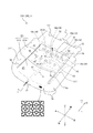
図1は、本発明の様々な実施形態に係る多孔質構造体1から構成されることができるシートパッド302を備えた車両用シート300の一例を、概略的に示す斜視図である。
図1に破線で示すように、車両用シート300は、着座者が着座するためのクッションパッド310と、着座者の背中を支持するためのバックパッド320と、を備えている。クッションパッド310とバックパッド320とは、それぞれ、シートパッド302から構成されている。以下では、クッションパッド310又はバックパッド320を、単に「シートパッド302」と呼ぶことがある。クッションパッド310とバックパッド320とは、それぞれ、後述する任意の例の多孔質構造体1から構成されることができる。多孔質構造体1は、多数のセル孔を有している。車両用シート300は、クッションパッド310及びバックパッド320のそれぞれを構成するシートパッド302に加え、例えば、シートパッド302の表側(着座者側)を覆う表皮330と、クッションパッド310を下側から支持するフレーム(図示せず)と、バックパッド320の裏側に設置されるフレーム(図示せず)と、バックパッド320の上側に設置され、着座者の頭部を支持するためのヘッドレスト340と、を備えることができる。表皮330は、例えば、通気性のよい材料(布等)から構成される。図1の例において、クッションパッド310とバックパッド320とは、互いに別体に構成されているが、互いに一体に構成されてもよい。
また、図1の例において、ヘッドレスト340は、バックパッド320とは別体に構成されているが、ヘッドレスト340は、バックパッド320と一体に構成されてもよい。
本明細書では、図1〜図5に表記するとおり、車両用シート300(ひいてはシートパッド302)に着座した着座者から観たときの「上」、「下」、「左」、「右」、「前」、「後」の各方向を、それぞれ単に「上」、「下」、「左」、「右」、「前」、「後」などという。
[Seat pad according to the first embodiment]
The seat pad 302 according to the first embodiment of the present invention will be described with reference to FIGS. 1 to 5.
FIG. 1 is a perspective view schematically showing an example of a vehicle seat 300 provided with a seat pad 302 that can be composed of the porous structure 1 according to various embodiments of the present invention.
As shown by the broken line in FIG. 1, the vehicle seat 300 includes a cushion pad 310 for the seated person to sit on, and a back pad 320 for supporting the back of the seated person. The cushion pad 310 and the back pad 320 are each composed of a seat pad 302. Hereinafter, the cushion pad 310 or the back pad 320 may be simply referred to as a "seat pad 302". The cushion pad 310 and the back pad 320 can each be composed of the porous structure 1 of any example described later. The porous structure 1 has a large number of cell holes. The vehicle seat 300 supports, for example, the skin 330 that covers the front side (seat side) of the seat pad 302 and the cushion pad 310 from below, in addition to the seat pad 302 that constitutes each of the cushion pad 310 and the back pad 320. A frame (not shown), a frame (not shown) installed on the back side of the back pad 320, and a headrest 340 installed on the upper side of the back pad 320 to support the head of the seated person. Can be prepared. The skin 330 is made of, for example, a highly breathable material (cloth or the like). In the example of FIG. 1, the cushion pad 310 and the back pad 320 are configured separately from each other, but may be configured integrally with each other.
Further, in the example of FIG. 1, the headrest 340 is configured separately from the back pad 320, but the headrest 340 may be configured integrally with the back pad 320.
In the present specification, as shown in FIGS. 1 to 5, "upper", "lower", "left", and "right" when viewed from a seated person seated on the vehicle seat 300 (and thus the seat pad 302). , "Front" and "rear" are simply referred to as "up", "down", "left", "right", "front", "rear" and the like.

以下では、説明の便宜のため、第1実施形態に係るシートパッド302からなるクッションパッド310及びバックパッド320について、併せて説明する。 Hereinafter, for convenience of explanation, the cushion pad 310 and the back pad 320 including the seat pad 302 according to the first embodiment will be described together.

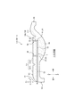
図2及び図3は、第1実施形態に係るシートパッド302からなるクッションパッド310の一例を示している。図2は、クッションパッド310を上側から観たときの斜視図であり、図3は、図2のクッションパッド310を、前後方向(クッションパッド310の延在方向LDでもある。)に延在する図2のI−I線に沿う断面により示している。図2及び図3に示すように、クッションパッド310は、着座者の臀部及び大腿部を下側から支持するように構成されたメインパッド部311と、メインパッド部311の左右両側に位置し、メインパッド部311よりも上側へ盛り上がり、着座者を左右両側から支持するように構成された、一対のサイドパッド部312と、メインパッド部311の後側に位置し、バックパッド320と上下方向に対向配置するように構成された、バックパッド対向部313と、を有している。メインパッド部311は、着座者の大腿部を下側から支持するように構成された、腿下部311tと、腿下部311tに対し後側に位置し、着座者の尻部を下側から支持するように構成された尻下部311hと、からなる。 2 and 3 show an example of a cushion pad 310 including the seat pad 302 according to the first embodiment. FIG. 2 is a perspective view of the cushion pad 310 when viewed from above, and FIG. 3 shows the cushion pad 310 of FIG. 2 extending in the front-rear direction (also the extending direction LD of the cushion pad 310). It is shown by a cross section along the line I-I of FIG. As shown in FIGS. 2 and 3, the cushion pad 310 is located on the left and right sides of the main pad portion 311 configured to support the buttocks and thighs of the seated person from below, and the main pad portion 311. , A pair of side pad portions 312, which are configured to swell upward from the main pad portion 311 and support the seated person from both left and right sides, and are located on the rear side of the main pad portion 311 and vertically with the back pad 320. It has a back pad facing portion 313, which is configured to face each other. The main pad portion 311 is located on the rear side with respect to the lower thigh 311t and the lower thigh 311t, which are configured to support the thigh of the seated person from the lower side, and supports the buttocks of the seated person from the lower side. It consists of a lower buttock 311h configured to do so.

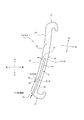
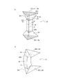
図4及び図5は、第1実施形態に係るシートパッド302からなるバックパッド320の一例を示している。図4は、バックパッド320を前側から観たときの斜視図であり、図5は、図4のバックパッド320を、バックパッド320の延在方向LDに延在する図4のK−K線に沿う断面により示している。図4及び図5に示すように、バックパッド320は、着座者の背中を後側から支持するように構成されたメインパッド部321と、メインパッド部321の左右両側に位置し、メインパッド部321よりも前側へ盛り上がり、着座者を左右両側から支持するように構成された、一対のサイドパッド部322と、を有している。 4 and 5 show an example of the back pad 320 including the seat pad 302 according to the first embodiment. FIG. 4 is a perspective view of the back pad 320 when viewed from the front side, and FIG. 5 is a line KK of FIG. 4 extending the back pad 320 of FIG. 4 in the extending direction LD of the back pad 320. It is shown by the cross section along. As shown in FIGS. 4 and 5, the back pad 320 is located on both the left and right sides of the main pad portion 321 configured to support the back of the seated person from the rear side and the main pad portion 321. It has a pair of side pad portions 322 that swell to the front side of 321 and are configured to support the seated person from both the left and right sides.

本明細書において、「シートパッド(302)の延在方向(LD)」(以下、単に「延在方向(LD)」ともいう。)とは、シートパッド302の左右方向及び厚さ方向(TD)に対して垂直な方向であり、クッションパッド310の場合は前後方向を指しており(図2及び図3)、バックパッド320の場合はバックパッド320のメインパッド部321の下面から上面までにわたってメインパッド部321が延在する方向を指している(図4及び図5)。
また、「シートパッド(302)の厚さ方向(TD)」(以下、単に「厚さ方向(TD)」ともいう。)とは、クッションパッド310の場合、上下方向を指しており(図2及び図3)、バックパッド320の場合、バックパッド320のメインパッド部321の着座者側の面(表面)FSから裏面BSまでにわたってメインパッド部321が延在する方向である(図4及び図5)。
また、シートパッド(302)の「着座者側の面(表面、FS)」は、クッションパッド310の場合は上面を指しており(図2及び図3)、バックパッド320の場合は前面を指している(図4及び図5)。シートパッド(302)の「裏面(BS)」は、シートパッド(302)の着座者側の面(FS)とは反対側の面であり、クッションパッド310の場合は下面を指しており(図2及び図3)、バックパッド320の場合は後面を指している(図4及び図5)。シートパッド(302)の「側面(SS)」は、シートパッド(302)の着座者側の面(FS)と裏面(BS)との間の面であり、クッションパッド310の場合は前面、後面、左面及び右面のうちいずれかを指しており(図2及び図3)、バックパッド320の場合は下面、上面、左面及び右面のうちいずれかを指している(図4及び図5)。
In the present specification, the "extending direction (LD) of the seat pad (302)" (hereinafter, also simply referred to as "extending direction (LD)") refers to the lateral direction and the thickness direction (TD) of the seat pad 302. ), In the case of the cushion pad 310, it points in the front-rear direction (FIGS. 2 and 3), and in the case of the back pad 320, from the lower surface to the upper surface of the main pad portion 321 of the back pad 320. The main pad portion 321 points in the extending direction (FIGS. 4 and 5).
Further, the "thickness direction (TD) of the seat pad (302)" (hereinafter, also simply referred to as "thickness direction (TD)") refers to the vertical direction in the case of the cushion pad 310 (FIG. 2). In the case of the back pad 320, the main pad portion 321 extends from the seater-side surface (front surface) FS of the main pad portion 321 of the back pad 320 to the back surface BS (FIGS. 4 and 3). 5).
Further, the "seat side surface (surface, FS)" of the seat pad (302) refers to the upper surface in the case of the cushion pad 310 (FIGS. 2 and 3) and the front surface in the case of the back pad 320. (Fig. 4 and Fig. 5). The “back surface (BS)” of the seat pad (302) is the surface of the seat pad (302) opposite to the seating side surface (FS), and in the case of the cushion pad 310, it refers to the lower surface (FIG. 2 and FIG. 3), in the case of the back pad 320, it points to the rear surface (FIGS. 4 and 5). The "side surface (SS)" of the seat pad (302) is the surface between the seated side surface (FS) and the back surface (BS) of the seat pad (302), and in the case of the cushion pad 310, the front surface and the rear surface. , Left surface and right surface (FIGS. 2 and 3), and in the case of the back pad 320, it refers to any one of the lower surface, the upper surface, the left surface and the right surface (FIGS. 4 and 5).

クッションパッド310は、図2の例において、その着座者側の面FSに、それぞれ略前後方向(延在方向LD)に延在するとともに互いから左右方向に離間した、複数本(図の例では、2本)の溝Gaと、それぞれ略左右方向に延在する、1本又は複数本(図の例では、2本)の溝Gbと、を有している。図2の例において、略前後方向(延在方向LD)に延在する2本の溝Gaが、それぞれ、メインパッド部311とサイドパッド部312との間の境界をなしており、略左右方向に延在する2本の溝Gbのうち、前側に位置するほうの溝Gbが、腿下部311tと尻下部311hとの間の境界をなしており、また、略左右方向に延在する2本の溝Gbのうち、後側に位置するほうの溝Gbが、尻下部311h(ひいては、メインパッド部311)とバックパッド対向部313との間の境界をなしている。ただし、クッションパッド310の着座者側の面FSには、図2とは異なる形態で溝Ga、Gbが形成されていてもよい。また、クッションパッド310の腿下部311t、尻下部311h、サイドパッド部312、バックパッド対向部313どうしの間の境界は、溝Ga、Gbの位置とは異なる位置にあってもよい。
バックパッド320は、図4の例において、その着座者側の面FSに、それぞれ略延在方向LDに延在するとともに互いから左右方向に離間した、複数本(図の例では、2本)の溝Gaと、それぞれ略左右方向に延在する、1本又は複数本(図の例では、1本)の溝Gbと、を有している。図4の例において、略延在方向LDに延在する2本の溝Gaが、それぞれ、メインパッド部321とサイドパッド部322との間の境界をなしている。ただし、バックパッド320の着座者側の面FSには、図4とは異なる形態で溝Ga、Gbが形成されていてもよい。また、バックパッド320の着座者側の面FSには、略左右方向に延在する溝Gbが設けられていなくてもよい。また、バックパッド320のメインパッド部321及びサイドパッド部322どうしの間の境界は、溝Gaの位置とは異なる位置にあってもよい。
これらの溝Ga、Gbには、例えば、表皮330(図1)を取り付けるための取付具が設けられる。
In the example of FIG. 2, a plurality of cushion pads 310 extend in the substantially front-rear direction (extending direction LD) and are separated from each other in the left-right direction on the surface FS on the seater side (in the example of the figure). , 2) grooves Ga, and one or more (two in the example of the figure) grooves Gb extending substantially in the left-right direction. In the example of FIG. 2, the two grooves Ga extending in the substantially anteroposterior direction (extending direction LD) form a boundary between the main pad portion 311 and the side pad portion 312, respectively, and form a boundary in the substantially left-right direction. Of the two grooves Gb extending in the right direction, the groove Gb located on the front side forms a boundary between the lower thigh 311t and the lower buttock 311h, and the two grooves extend substantially in the left-right direction. Of the grooves Gb, the groove Gb located on the rear side forms a boundary between the lower tail portion 311h (by extension, the main pad portion 311) and the back pad facing portion 313. However, grooves Ga and Gb may be formed on the seater-side surface FS of the cushion pad 310 in a form different from that shown in FIG. Further, the boundary between the lower thigh 311t, the lower buttock 311h, the side pad portion 312, and the back pad facing portion 313 of the cushion pad 310 may be at a position different from the positions of the grooves Ga and Gb.
In the example of FIG. 4, a plurality of back pads 320 extend in the substantially extending direction LD and are separated from each other in the left-right direction on the surface FS on the seater side (two in the example of the figure). It has one or more grooves Gb (one in the example of the figure) extending substantially in the left-right direction. In the example of FIG. 4, the two grooves Ga extending in the substantially extending direction LD form a boundary between the main pad portion 321 and the side pad portion 322, respectively. However, grooves Ga and Gb may be formed on the seated side surface FS of the back pad 320 in a form different from that in FIG. Further, the surface FS on the seater side of the back pad 320 may not be provided with a groove Gb extending substantially in the left-right direction. Further, the boundary between the main pad portion 321 and the side pad portion 322 of the back pad 320 may be at a position different from the position of the groove Ga.
In these grooves Ga and Gb, for example, a fitting for attaching the skin 330 (FIG. 1) is provided.

上述のように、シートパッド302は、多孔質構造体1から構成される。シートパッド302は、3Dプリンタによって造形されたものである。シートパッド302の製造方法については、後に図11を参照しつつ詳述する。3Dプリンタを用いてシートパッド302を製造することにより、従来のように化学反応により発泡させる工程を経る場合に比べ、製造が簡単になり、かつ、所期したとおりの構成が得られる。また、今後の3Dプリンタの技術進歩により、将来的に、3Dプリンタによる製造を、より短時間かつ低コストで、実現できるようになることが期待できる。また、3Dプリンタを用いてシートパッド302を製造することにより、様々な要求特性に対応したシートパッド302の構成を、簡単かつ所期したとおりに実現できる。 As described above, the seat pad 302 is composed of the porous structure 1. The seat pad 302 is modeled by a 3D printer. The method for manufacturing the seat pad 302 will be described in detail later with reference to FIG. By manufacturing the seat pad 302 using a 3D printer, the manufacturing becomes simpler and the desired configuration can be obtained as compared with the case of undergoing the step of foaming by a chemical reaction as in the conventional case. In addition, it is expected that future technological advances in 3D printers will make it possible to realize manufacturing with 3D printers in a shorter time and at lower cost. Further, by manufacturing the seat pad 302 using a 3D printer, it is possible to easily and as expected the configuration of the seat pad 302 corresponding to various required characteristics.

多孔質構造体1は、可撓性のある樹脂又はゴムから構成されている。
ここで、「可撓性のある樹脂」とは、外力が加わると変形することができる樹脂を指しており、例えば、エラストマー系の樹脂が好適であり、ポリウレタンがより好適である。ゴムとしては、天然ゴム又は合成ゴムが挙げられる。多孔質構造体1は、可撓性のある樹脂又はゴムから構成されているので、着座者からの外力の付加・解除に応じて、圧縮・復元変形が可能であるので、クッション性を有することができる。
なお、3Dプリンタによる製造のし易さの観点からは、多孔質構造体1は、可撓性のある樹脂から構成されている場合のほうが、ゴムから構成されている場合よりも、好適である。
また、3Dプリンタによる製造のし易さの観点からは、多孔質構造体1は、その全体が、同じ組成の材料から構成されていると、好適である。ただし、多孔質構造体1は、部位によって異なる組成の材料から構成されてもよい。
The porous structure 1 is made of a flexible resin or rubber.
Here, the "flexible resin" refers to a resin that can be deformed when an external force is applied. For example, an elastomer-based resin is preferable, and polyurethane is more preferable. Examples of the rubber include natural rubber and synthetic rubber. Since the porous structure 1 is made of a flexible resin or rubber, it can be compressed / restored and deformed according to the application / release of an external force from the seated person, and thus has cushioning properties. Can be done.
From the viewpoint of ease of manufacture by a 3D printer, the porous structure 1 is more preferably made of a flexible resin than that of a rubber. ..
Further, from the viewpoint of ease of production by a 3D printer, it is preferable that the entire porous structure 1 is made of a material having the same composition. However, the porous structure 1 may be composed of materials having different compositions depending on the site.

多孔質構造体1の好適なセル構造については、後に図6〜図10等を参照しながら詳しく説明する。 The suitable cell structure of the porous structure 1 will be described in detail later with reference to FIGS. 6 to 10 and the like.

図2〜図5に示すように、第1実施形態のシートパッド302(クッションパッド310、バックパッド320)は、シートパッド302の外表面に開口する複数の開口51、52どうしの間において、流体が通るための流体通路5を有している。より具体的に、流体通路5は、シートパッド302の外表面に開口する1つ又は複数の第1開口51から、シートパッド302の内部を延在し、シートパッド302の外表面に開口する1つ又は複数の第2開口52までに至るものである。第2開口52は、シートパッド302の着座者側の面FSに開口している。第1開口51は、シートパッド302の外表面における任意の位置に配置されてよいが、シートパッド302の外表面のうち着座者側の面FS以外の面に開口していると好適である。
ここで、シートパッド302の「外表面」とは、シートパッド302の着座者側の面FS、裏面BS及び側面SSを包括して指しており、着座者側の面FSに設けられた溝Ga、Gbの側面及び底面をも含んでいる。したがって、第2開口52は、着座者側の面FSに設けられた溝Ga、Gbの側面及び/又は底面に開口していてもよい。
流体通路5は、シートパッド302を構成する多孔質構造体1によって区画されており、流体通路5の内部は空洞である。
流体通路5は、例えば、車内のエアコン(図示せず)からの風(温風、冷風等)を通すために好適に用いることができる。この場合、第1開口51は、エアコンの排出口に連結され、エアコンからの風が流入されるための入口として使用され、第2開口52は、出口として使用されると、好適である。また、流体通路5は、エアコンに連結されていなくてもよく、例えば、開口51、52どうしの間を自然に空気が通ることで換気が行われるように使用されてもよい。
As shown in FIGS. 2 to 5, the seat pad 302 (cushion pad 310, back pad 320) of the first embodiment is a fluid between a plurality of openings 51, 52 that open on the outer surface of the seat pad 302. It has a fluid passage 5 for passing through. More specifically, the fluid passage 5 extends inside the seat pad 302 from one or more first openings 51 that open to the outer surface of the seat pad 302 and opens to the outer surface of the seat pad 302. It reaches up to one or a plurality of second openings 52. The second opening 52 opens on the seating side surface FS of the seat pad 302. The first opening 51 may be arranged at an arbitrary position on the outer surface of the seat pad 302, but it is preferable that the first opening 51 is opened on a surface other than the surface FS on the seater side of the outer surface of the seat pad 302.
Here, the "outer surface" of the seat pad 302 includes the surface FS on the seater side, the back surface BS, and the side surface SS of the seat pad 302, and the groove Ga provided on the surface FS on the seater side. , Also includes the sides and bottom of Gb. Therefore, the second opening 52 may be opened on the side surface and / or the bottom surface of the grooves Ga and Gb provided on the surface FS on the seater side.
The fluid passage 5 is partitioned by the porous structure 1 constituting the seat pad 302, and the inside of the fluid passage 5 is hollow.
The fluid passage 5 can be suitably used, for example, to pass air (hot air, cold air, etc.) from an air conditioner (not shown) in the vehicle. In this case, it is preferable that the first opening 51 is connected to the outlet of the air conditioner and is used as an inlet for the air from the air conditioner to flow in, and the second opening 52 is used as an outlet. Further, the fluid passage 5 does not have to be connected to the air conditioner, and may be used so that ventilation is performed by naturally passing air between the openings 51 and 52, for example.

より具体的に、図2〜図3に示すクッションパッド310(シートパッド302)の例においては、流体通路5が、1つの第1開口51と、複数(具体的には10個)の第2開口52と、を有しており、第1開口51から各第2開口52までの間にわたって、シートパッド302の内部を延在している。第1開口51は、シートパッド302の側面SSのうちの前面に開口している。各第2開口は、それぞれ、シートパッド302の尻下部311hの着座者側の面FSに開口している。
本例において、流体通路5は、第1開口51から連続して第2開口52側に向かって延在する本通路53と、本通路53上の1つ又は複数の分岐点P(以下、「第1分岐点P1」という。)のそれぞれから分岐した、1つ又は複数の分岐部56と、を有している。図の例において、流体通路5は、本通路53の延在方向における複数(図の例では、2つ)の異なる位置に、第1分岐点P1を、それぞれ有しており、分岐部56を複数(図の例では、2つ)有している。図の例において、本通路53は、略延在方向LD(略前後方向)に延在している。
ここで、「分岐点(P、P1、P2)」とは、流体通路5において1つの通路が複数の通路に分岐する箇所(分岐の起点)を指す。
各分岐部56は、それぞれ、1つ又は複数(図の例では、5つ)の分岐通路54を有している。各分岐通路54は、それぞれ、第2開口52を有している。ここで、本例において、各分岐通路54は、それぞれ、分岐部56のうち、第2開口52を含む末端の通路であり、具体的には、例えば、第1分岐点P1を起点として他の分岐点Pを介さずに第2開口52まで延在するか、又は、流体通路5において第1分岐点P1よりも第2開口52側に位置する他の1つ又は複数の分岐点Pのうち最も第2開口52側の分岐点P(図の例では、第2分岐点P2)を起点として、第2開口52まで延在する。第1分岐点P1と分岐通路54との間に他の分岐点P(図の例では、第2分岐点P2)がある場合、第1分岐点P1と当該他の分岐点Pとの間には、中間通路55が延在する。
図2の例において、分岐部56を構成する複数(図の例では5つ)の分岐通路54は、シートパッド302の平面視において本通路53に対し交差(例えば直交)する方向(図の例では、左右方向)に沿って配列されている。
ここで、「シートパッド302の平面視」とは、シートパッド302を、シートパッド302の着座者側の面FSに対して垂直に観たときの平面視を指す。
分岐部56を構成する複数(図の例では5つ)の分岐通路54のうち、1つの分岐通路54aは、第1分岐点P1から着座者側(上側)に向かって略厚さ方向TD(略上下方向)に延在して、第2開口52に至っている。また、分岐部56では、第1分岐点P1から一対の中間通路55が左右両側へ向かって延在し、各中間通路55の終端にそれぞれ第2分岐点P2があり、各第2分岐点P2からそれぞれ複数(図の例では、2つ)の分岐通路54b、54cが延在している。各中間通路55は、シートパッド302の平面視において、本通路53に対し交差(例えば直交)する方向(図の例では、左右方向)に延在している。図2の例のように、第2分岐点P2から延在する複数(図の例では、2つ)の分岐通路54b、54cは、例えば、第2分岐点P2から、着座者側(上側)に向かって略厚さ方向TD(略上下方向)に延在して、第2開口52に至る、分岐通路54bを、含むことができる。かつ/又は、第2分岐点P2から延在する複数(図の例では、2つ)の分岐通路54b、54cは、例えば、第2分岐点P2から、シートパッド302の平面視において本通路53に対し交差(例えば直交)する方向(図の例では、左右方向)に延在した後、屈曲又は湾曲してから、着座者側(上側)に向かって略厚さ方向TD(略上下方向)に延在して、第2開口52に至る、分岐通路54cを、含むことができる。
More specifically, in the example of the cushion pad 310 (seat pad 302) shown in FIGS. 2 to 3, the fluid passage 5 has one first opening 51 and a plurality (specifically, 10) second fluid passages 5. It has an opening 52, and extends inside the seat pad 302 from the first opening 51 to each of the second openings 52. The first opening 51 opens to the front surface of the side surface SS of the seat pad 302. Each of the second openings opens on the seater-side surface FS of the lower buttock 311h of the seat pad 302.
In this example, the fluid passage 5 includes a main passage 53 that extends continuously from the first opening 51 toward the second opening 52 side, and one or more branch points P on the main passage 53 (hereinafter, "" It has one or a plurality of branch portions 56 branched from each of the first branch points P1 ”). In the example of the figure, the fluid passage 5 has a first branch point P1 at a plurality of different positions (two in the example of the figure) in the extending direction of the main passage 53, and has a branch portion 56. It has a plurality (two in the example of the figure). In the example of the figure, the passage 53 extends in the substantially extending direction LD (substantially the front-rear direction).
Here, the "branch point (P, P1, P2)" refers to a point (starting point of branching) in the fluid passage 5 where one passage branches into a plurality of passages.
Each branch 56 has one or more (five in the example of the figure) branch passages 54, respectively. Each branch passage 54 has a second opening 52, respectively. Here, in this example, each branch passage 54 is a terminal passage including the second opening 52 of the branch portion 56, and specifically, for example, another branch passage P1 as a starting point. Of the other branch points P that extend to the second opening 52 without passing through the branch point P, or are located on the second opening 52 side of the first branch point P1 in the fluid passage 5. Starting from the branch point P on the side of the second opening 52 (in the example of the figure, the second branch point P2), it extends to the second opening 52. When there is another branch point P (in the example of the figure, the second branch point P2) between the first branch point P1 and the branch passage 54, the first branch point P1 and the other branch point P are between. The intermediate passage 55 extends.
In the example of FIG. 2, the plurality of (five in the example of the figure) branch passages 54 constituting the branch portion 56 intersect (for example, orthogonal to) the main passage 53 in the plan view of the seat pad 302 (example of the figure). Then, they are arranged along the left-right direction).
Here, the "plan view of the seat pad 302" refers to a plan view when the seat pad 302 is viewed perpendicularly to the surface FS on the seater side of the seat pad 302.
Of the plurality of (five in the example of the figure) branch passages 54 constituting the branch portion 56, one branch passage 54a is TD in the substantially thickness direction from the first branch point P1 toward the seater side (upper side). It extends in the vertical direction) and reaches the second opening 52. Further, in the branch portion 56, a pair of intermediate passages 55 extend from the first branch point P1 toward both left and right sides, and there is a second branch point P2 at the end of each intermediate passage 55, and each second branch point P2. A plurality of (two in the example of the figure) branch passages 54b and 54c extend from each of the above. Each intermediate aisle 55 extends in a direction (for example, a left-right direction in the example of the figure) intersecting (for example, orthogonal to) the main aisle 53 in a plan view of the seat pad 302. As in the example of FIG. 2, the plurality of (two in the example of the figure) branch passages 54b and 54c extending from the second branch point P2 are, for example, from the second branch point P2 on the seated side (upper side). A branch passage 54b extending in the substantially thickness direction TD (approximately vertical direction) toward the second opening 52 and reaching the second opening 52 can be included. And / or the plurality of (two in the example of the figure) branch passages 54b and 54c extending from the second branch point P2 are, for example, from the second branch point P2 to the main passage 53 in the plan view of the seat pad 302. After extending in a direction that intersects (for example, orthogonally) with respect to (for example, in the left-right direction in the example of the figure), bends or bends, and then substantially a thickness direction TD (approximately vertical direction) toward the seater side (upper side). A branch passage 54c that extends to the second opening 52 and reaches the second opening 52 can be included.

また、図4〜図5に示すバックパッド320(シートパッド302)の例においては、流体通路5が、1つの第1開口51と、複数(具体的には6個)の第2開口52と、を有しており、第1開口51から各第2開口52までの間にわたって、シートパッド302の内部を延在している。第1開口51は、シートパッド302の側面SSのうちの下面に開口している。各第2開口は、それぞれ、シートパッド302のメインパッド部321の着座者側の面FSに開口している。
本例において、流体通路5は、第1開口51から連続して第2開口52側に向かって延在する本通路53と、本通路53上の1つ又は複数の分岐点P(以下、「第1分岐点P1」という。)のそれぞれから分岐した、1つ又は複数の分岐部56と、を有している。図の例において、流体通路5は、本通路53の延在方向における複数(図の例では、2つ)の異なる位置に、第1分岐点P1を、それぞれ有しており、分岐部56を複数(図の例では、2つ)有している。図の例において、本通路53は、略延在方向LDに延在している。
各分岐部56は、それぞれ、1つ又は複数(図の例では、3つ)の分岐通路54を有している。各分岐通路54は、それぞれ、第2開口52を有している。ここで、本例において、各分岐通路54は、それぞれ、分岐部56のうち、第2開口52を含む末端の通路であり、具体的には、例えば、第1分岐点P1を起点として他の分岐点Pを介さずに第2開口52まで延在するか、又は、流体通路5において第1分岐点P1よりも第2開口52側に位置する他の1つ又は複数の分岐点P(図の例では、存在しない)のうち最も第2開口52側の分岐点Pを起点として、第2開口52まで延在する。第1分岐点P1と分岐通路54との間に他の分岐点P(図の例では、存在しない)がある場合、第1分岐点P1と当該他の分岐点Pとの間には、中間通路55(図の例では、存在しない)が延在する。
図4の例において、分岐部56を構成する複数(図の例では3つ)の分岐通路54は、シートパッド302の平面視において本通路53に対し交差(例えば直交)する方向(図の例では、左右方向)に沿って配列されている。
図4の例において、分岐部56を構成する複数(図の例では3つ)の分岐通路54は、それぞれ、第1分岐点P1を起点として他の分岐点Pを介さずに第2開口52まで延在している。そのうち、1つの分岐通路54dは、第1分岐点P1から着座者側(前側)に向かって略厚さ方向TDに延在して、第2開口52に至っている。また、残り(図の例では2つ)の分岐通路54eは、それぞれ、第1分岐点P1から、シートパッド302の平面視において本通路53に対し交差(例えば直交)する方向(図の例では、左右方向)に延在した後、屈曲又は湾曲してから、着座者側(前側)に向かって略厚さ方向TDに延在して、第2開口52に至る。
Further, in the example of the back pad 320 (seat pad 302) shown in FIGS. 4 to 5, the fluid passage 5 has one first opening 51 and a plurality of (specifically six) second openings 52. , And extends inside the seat pad 302 from the first opening 51 to each second opening 52. The first opening 51 opens on the lower surface of the side surface SS of the seat pad 302. Each of the second openings opens on the seater-side surface FS of the main pad portion 321 of the seat pad 302.
In this example, the fluid passage 5 includes a main passage 53 that extends continuously from the first opening 51 toward the second opening 52 side, and one or more branch points P on the main passage 53 (hereinafter, "" It has one or a plurality of branch portions 56 branched from each of the first branch points P1 ”). In the example of the figure, the fluid passage 5 has a first branch point P1 at a plurality of different positions (two in the example of the figure) in the extending direction of the main passage 53, and has a branch portion 56. It has a plurality (two in the example of the figure). In the example of the figure, the passage 53 extends in the substantially extending direction LD.
Each branch 56 has one or more (three in the example of the figure) branch passages 54, respectively. Each branch passage 54 has a second opening 52, respectively. Here, in this example, each branch passage 54 is a terminal passage including the second opening 52 of the branch portion 56, and specifically, for example, another branch passage P1 as a starting point. One or more branch points P that extend to the second opening 52 without passing through the branch point P, or are located on the second opening 52 side of the first branch point P1 in the fluid passage 5 (FIG. In the example of), the branch point P on the side of the second opening 52 is the starting point and extends to the second opening 52. If there is another branch point P (does not exist in the example of the figure) between the first branch point P1 and the branch passage 54, the middle between the first branch point P1 and the other branch point P is intermediate. The passage 55 (which does not exist in the example of the figure) extends.
In the example of FIG. 4, the plurality of (three in the example of the figure) branch passages 54 constituting the branch portion 56 intersect (for example, orthogonal to) the main passage 53 in the plan view of the seat pad 302 (example of the figure). Then, they are arranged along the left-right direction).
In the example of FIG. 4, each of the plurality of branch passages 54 (three in the example of the figure) constituting the branch portion 56 starts from the first branch point P1 and does not go through the other branch points P, but the second opening 52. It has been extended to. Among them, one branch passage 54d extends from the first branch point P1 toward the seater side (front side) in the substantially thickness direction TD and reaches the second opening 52. Further, the remaining (two in the example of the figure) branch passages 54e intersect (for example, orthogonally) the main passage 53 in the plan view of the seat pad 302 from the first branch point P1 (in the example of the figure). After extending in the left-right direction), it bends or curves, and then extends in the substantially thickness direction TD toward the seater side (front side) to reach the second opening 52.

ここで、本実施形態の効果について説明する。
まず、仮に上述した従来のように化学反応により発泡させる工程を経てシートパッド302を製造する場合、シートパッド302の外表面に開口する第1開口51から、シートパッド302の内部を延在し、シートパッド302の外表面に開口する第2開口52までに至る、流体通路5を、形成することは難しい。例えば、金型を用いてシートパッド302を発泡成形する場合、流体通路5を金型成形面により成形する必要があるが、型抜きが難しくなる。また、例えば、シートパッド302のうち、流体通路5の流路軸線(流路の中心軸線)に対する両側一対の部分を別々に成形し、その後、両者を貼り付けることも考えられるが、製造工程が増える。また、実現可能な流体通路5の構成には限りがある。
これに対し、本実施形態によれば、シートパッド302(クッションパッド310、バックパッド320)が3Dプリンタによって造形されるので、流体通路5を有するシートパッド302を、1つの工程で、簡単に製造することができる。また、仮に化学反応により発泡させる工程を経てシートパッド302を製造する場合に比べて、流体通路5の設計自由度を大幅に広げることができ、また、流体通路5がいかなる構成を有していても、流体通路5を有するシートパッド302を、所期したとおりに精度良く製造することができる。
また、本実施形態において、シートパッド302(クッションパッド310、バックパッド320)は、流体通路5を有するので、例えば流体通路5をエアコンの排出口と連結した場合に、エアコン(図示せず)からの風(温風、冷風等)を流体通路5に流すことで、シートパッド302及び着座者の温度調節を効果的に行うことが可能になる。また、流体通路5をエアコンの排出口と連結しない場合であっても、シートパッド302の通気性(ひいては換気性能)を向上できるので、自然換気によって、シートパッド302の内部の空気をシートパッド302の外部の空気と効果的に入れ換えることができる。よって、例えば、車内のエアコンによって温度調節された空気をシートパッド302の内部に送り込みやすくなり、シートパッド302及び着座者の温度調節を効果的に行うことができるので、エアコンの効きを向上でき、また、シートパッド302の内部の湿気を効果的に排出することができる。
また、本実施形態において、流体通路5の第2開口52は、シートパッド302(クッションパッド310、バックパッド320)の着座者側の面FSに開口している(図2、図4)。これにより、仮に第1開口51をエアコンの排出口と連結した場合に、エアコンのからの風が、着座者側の面FSに設けられた第2開口52から、着座者に向けて排出されるようにすることができるので、着座者はエアコンからの風を直に受けることができ、ひいては、着座者の温度調節をより効果的に行うことができる。また、流体通路5をエアコンの排出口と連結しない場合であっても、自然換気によって、シートパッド302のうち、着座者に最も近い位置にある着座者側の面FS近傍部分の空気を、シートパッド302の外部の空気と効果的に入れ換えることができるので、特に温度調節や湿気除去が必要な部分で、温度調節や湿気除去を効果的に行うことができる。
Here, the effect of this embodiment will be described.
First, when the seat pad 302 is manufactured through the above-mentioned conventional step of foaming by a chemical reaction, the inside of the seat pad 302 extends from the first opening 51 that opens on the outer surface of the seat pad 302. It is difficult to form the fluid passage 5 up to the second opening 52 that opens to the outer surface of the seat pad 302. For example, when the seat pad 302 is foam-molded using a mold, the fluid passage 5 needs to be molded by the mold molding surface, but the die-cutting becomes difficult. Further, for example, in the seat pad 302, it is conceivable to separately form a pair of parts on both sides of the fluid passage 5 with respect to the flow path axis (center axis of the flow path), and then attach both of them, but the manufacturing process is Increase. In addition, the feasible configuration of the fluid passage 5 is limited.
On the other hand, according to the present embodiment, since the seat pad 302 (cushion pad 310, back pad 320) is modeled by the 3D printer, the seat pad 302 having the fluid passage 5 can be easily manufactured in one step. can do. Further, as compared with the case where the seat pad 302 is manufactured through the step of foaming by a chemical reaction, the degree of freedom in designing the fluid passage 5 can be greatly expanded, and the fluid passage 5 has any configuration. Also, the seat pad 302 having the fluid passage 5 can be manufactured with high accuracy as expected.
Further, in the present embodiment, since the seat pad 302 (cushion pad 310, back pad 320) has the fluid passage 5, for example, when the fluid passage 5 is connected to the outlet of the air conditioner, the air conditioner (not shown) By flowing the air (warm air, cold air, etc.) through the fluid passage 5, it becomes possible to effectively control the temperature of the seat pad 302 and the seated person. Further, even when the fluid passage 5 is not connected to the outlet of the air conditioner, the air permeability (and thus the ventilation performance) of the seat pad 302 can be improved. Therefore, the air inside the seat pad 302 is evacuated by natural ventilation. It can be effectively replaced with the outside air of. Therefore, for example, the air temperature-controlled by the air conditioner in the vehicle can be easily sent into the seat pad 302, and the temperature of the seat pad 302 and the seated person can be effectively controlled, so that the effectiveness of the air conditioner can be improved. In addition, the moisture inside the seat pad 302 can be effectively discharged.
Further, in the present embodiment, the second opening 52 of the fluid passage 5 is opened to the surface FS on the seater side of the seat pad 302 (cushion pad 310, back pad 320) (FIGS. 2 and 4). As a result, if the first opening 51 is connected to the outlet of the air conditioner, the wind from the air conditioner is discharged toward the seated person from the second opening 52 provided on the surface FS on the seated side. Therefore, the seated person can directly receive the wind from the air conditioner, and thus the temperature of the seated person can be controlled more effectively. Further, even when the fluid passage 5 is not connected to the outlet of the air conditioner, the air in the portion of the seat pad 302 near the surface FS on the seater side, which is closest to the seater, is removed by natural ventilation. Since it can be effectively replaced with the air outside the pad 302, the temperature control and the moisture removal can be effectively performed particularly in the portion where the temperature control and the moisture removal are required.

図2〜図5の各例においては、上述のように、流体通路5が、複数の分岐通路54を有しており、これら複数の分岐通路54は、それぞれ、シートパッド302(クッションパッド310、バックパッド320)の着座者側の面FSに開口する第2開口52を有している。これにより、仮に第1開口51をエアコンの排出口と連結した場合に、エアコンからの風を、複数の分散した位置にある第2開口52から、着座者に向けて排出することができるので、仮に流体通路5が分岐通路54を有していない場合(ひいては第2開口52を1つのみ有している場合)に比べて、着座者の温度調節をより効果的に行うことができる。また、流体通路5をエアコンの排出口と連結しない場合であっても、自然換気によって、シートパッド302のうち、特に温度調節や湿気除去が必要な、着座者側の面FS近傍部分の空気を、複数の分散した位置において、シートパッド302の外部の空気と効果的に入れ換えることができるので、温度調節や湿気除去をより効果的に行うことができる。
なお、図2〜図5の各例においては、流体通路5は、第2開口52側に複数の分岐通路54を有しているが、本明細書で説明する各例において、流体通路5は、第1開口51側に複数の分岐通路54を有していてもよく、すなわち、流体通路5は、複数の分岐通路54のそれぞれが、シートパッド302(クッションパッド310、バックパッド320)の着座者側の面FS以外の面に開口する第1開口51を有していてもよい。また、本明細書で説明する各例において、流体通路5は、第1開口51及び第2開口52をそれぞれ1つのみ有するとともに、第1開口51及び第2開口52どうしの間の中間部分のみで分岐した複数の分岐通路54を有していてもよい。
In each of the examples of FIGS. 2 to 5, as described above, the fluid passage 5 has a plurality of branch passages 54, and each of the plurality of branch passages 54 has a seat pad 302 (cushion pad 310, The back pad 320) has a second opening 52 that opens to the seated surface FS. As a result, if the first opening 51 is connected to the outlet of the air conditioner, the wind from the air conditioner can be discharged from the second openings 52 at a plurality of dispersed positions toward the seated person. As compared with the case where the fluid passage 5 does not have the branch passage 54 (and thus has only one second opening 52), the temperature control of the seated person can be performed more effectively. Further, even when the fluid passage 5 is not connected to the outlet of the air conditioner, the air in the seat pad 302 in the vicinity of the surface FS on the seater side, which requires temperature control and moisture removal, is evacuated by natural ventilation. Since the air outside the seat pad 302 can be effectively replaced at a plurality of dispersed positions, temperature control and moisture removal can be performed more effectively.
In each of the examples of FIGS. 2 to 5, the fluid passage 5 has a plurality of branch passages 54 on the second opening 52 side, but in each of the examples described in the present specification, the fluid passage 5 is , The first opening 51 may have a plurality of branch passages 54, that is, in the fluid passage 5, each of the plurality of branch passages 54 is seated on the seat pad 302 (cushion pad 310, back pad 320). It may have a first opening 51 that opens to a surface other than the surface FS on the person side. Further, in each example described in the present specification, the fluid passage 5 has only one first opening 51 and one second opening 52, and only an intermediate portion between the first opening 51 and the second opening 52. It may have a plurality of branch passages 54 branched at.

図2〜図3の例において、クッションパッド310として構成されたシートパッド302は、上述のように、流体通路5の第2開口52が、尻下部311hの着座者側の面FSに開口している。これにより、仮に第1開口51をエアコンの排出口と連結した場合に、エアコンからの風を、尻下部311hの着座者側の面FSに設けられた第2開口52から、着座者の尻部に向けて排出することができるので、仮に第2開口52が他の着座者側の面FS(例えば、サイドパッド部312の着座者側の面FS)に開口している場合に比べて、着座者の温度調節をより効果的に行うことができる。また、流体通路5をエアコンの排出口と連結しない場合であっても、自然換気によって、シートパッド302の着座者側の面FS近傍部分のうち、特に温度調節や湿気除去が必要な、尻下部311hの着座者側の面FS近傍部分の空気を、シートパッド302の外部の空気と効果的に入れ換えることができるので、温度調節や湿気除去をより効果的に行うことができる。
ただし、クッションパッド310として構成されたシートパッド302において、第2開口52は、シートパッド302の着座者側の面FSにおける任意の位置に開口していてよく、例えば、尻下部311hに加えて/代えて、腿下部311tの着座者側の面FSに開口していても、十分に効果的な温度調節や湿気除去が可能である。また、第2開口52は、サイドパッド部312の着座者側の面FSに開口していてもよい。
In the example of FIGS. 2 to 3, in the seat pad 302 configured as the cushion pad 310, as described above, the second opening 52 of the fluid passage 5 opens to the seater-side surface FS of the lower buttock 311h. There is. As a result, if the first opening 51 is connected to the outlet of the air conditioner, the wind from the air conditioner is blown from the second opening 52 provided on the seating side surface FS of the lower buttock 311h to the buttock portion of the seated person. Since the second opening 52 can be discharged toward, the seating is performed as compared with the case where the second opening 52 is opened to another seating side surface FS (for example, the seating side surface FS of the side pad portion 312). It is possible to control the temperature of the person more effectively. Further, even when the fluid passage 5 is not connected to the outlet of the air conditioner, the lower part of the tail where temperature control and moisture removal are particularly required in the portion near the surface FS on the seater side of the seat pad 302 by natural ventilation. Since the air in the vicinity of the surface FS on the seater side of 311h can be effectively replaced with the air outside the seat pad 302, temperature control and moisture removal can be performed more effectively.
However, in the seat pad 302 configured as the cushion pad 310, the second opening 52 may be opened at an arbitrary position on the seater-side surface FS of the seat pad 302, for example, in addition to the lower buttock 311h /. Instead, even if the lower part of the thigh 311t is opened on the seater-side surface FS, sufficiently effective temperature control and moisture removal are possible. Further, the second opening 52 may be opened to the surface FS on the seater side of the side pad portion 312.

図4〜図5の例において、バックパッド320として構成されたシートパッド302は、上述のように、流体通路5の第2開口52が、メインパッド部321の着座者側の面FSに開口している。これにより、仮に第1開口51をエアコンの排出口と連結した場合に、エアコンからの風を、メインパッド部321の着座者側の面FSに設けられた第2開口52から、着座者の背中に向けて排出することができるので、仮に第2開口52がサイドパッド部322の着座者側の面FSに開口している場合に比べて、着座者の温度調節をより効果的に行うことができる。また、流体通路5をエアコンの排出口と連結しない場合であっても、自然換気によって、シートパッド302の着座者側の面FS近傍部分のうち、特に温度調節や湿気除去が必要な、メインパッド部321の着座者側の面FS近傍部分の空気を、シートパッド302の外部の空気と効果的に入れ換えることができるので、温度調節や湿気除去をより効果的に行うことができる。
ただし、バックパッド320として構成されたシートパッド302において、第2開口52hは、シートパッド302の着座者側の面FSにおける任意の位置に開口していてよく、例えば、メインパッド部321に加えて/代えて、サイドパッド部322の着座者側の面FSに開口していても、効果的な温度調節や湿気除去が可能である。
In the example of FIGS. 4 to 5, in the seat pad 302 configured as the back pad 320, as described above, the second opening 52 of the fluid passage 5 opens to the surface FS on the seater side of the main pad portion 321. ing. As a result, if the first opening 51 is connected to the outlet of the air conditioner, the wind from the air conditioner is blown from the second opening 52 provided on the seater-side surface FS of the main pad portion 321 to the seater's back. Since the second opening 52 is opened to the surface FS on the seater side of the side pad portion 322, the temperature of the seated person can be controlled more effectively. it can. Further, even when the fluid passage 5 is not connected to the outlet of the air conditioner, the main pad which requires temperature control and moisture removal in the portion near the surface FS on the seater side of the seat pad 302 by natural ventilation. Since the air in the vicinity of the surface FS on the seater side of the portion 321 can be effectively replaced with the air outside the seat pad 302, temperature control and moisture removal can be performed more effectively.
However, in the seat pad 302 configured as the back pad 320, the second opening 52h may be opened at an arbitrary position on the seater side surface FS of the seat pad 302, and for example, in addition to the main pad portion 321. / Alternatively, even if the side pad portion 322 has an opening on the seating side surface FS, effective temperature control and moisture removal can be performed.

図2〜図5の各例においては、上述のように、流体通路5の第1開口51は、シートパッド302(クッションパッド310、バックパッド320)の外表面のうち着座者側の面以外の面FSに開口している。より具体的に、シートパッド302がクッションパッド310として構成された図2〜図3の例において、第1開口51は、シートパッド302の側面SSのうちの前面に開口している。また、シートパッド302がバックパッド320として構成された図4〜図5の例において、第1開口51は、シートパッド302の側面SSのうちの下面に開口している。これにより、仮に第1開口51をエアコンの排出口と連結した場合に、エアコンの排出口が着座者と干渉するのを抑制できる。また、流体通路5をエアコンの排出口と連結しない場合であっても、第1開口51と第2開口52との両方が着座者によって塞がれることによって自然換気がしにくくなるおそれを抑制できる。
なお、シートパッド302がクッションパッド310である場合、第1開口51は、シートパッド302の前面以外の側面SS(左面、右面、後面)、又は裏面BSに開口していても、同様の効果が得られる。また、シートパッド302がバックパッド320である場合、第1開口51は、シートパッド302の下面以外の側面SS(左面、右面、上面)、又は裏面BSに開口していても、同様の効果が得られる。
ただし、第1開口51は、シートパッド302(クッションパッド310、バックパッド320)の着座者側の面FSに開口していてもよい。
In each of the examples of FIGS. 2 to 5, as described above, the first opening 51 of the fluid passage 5 is the outer surface of the seat pad 302 (cushion pad 310, back pad 320) other than the surface on the seater side. It is open to the surface FS. More specifically, in the example of FIGS. 2 to 3 in which the seat pad 302 is configured as the cushion pad 310, the first opening 51 opens to the front surface of the side surface SS of the seat pad 302. Further, in the example of FIGS. 4 to 5 in which the seat pad 302 is configured as the back pad 320, the first opening 51 is opened on the lower surface of the side surface SS of the seat pad 302. As a result, if the first opening 51 is connected to the outlet of the air conditioner, the outlet of the air conditioner can be prevented from interfering with the seated person. Further, even when the fluid passage 5 is not connected to the outlet of the air conditioner, it is possible to suppress the possibility that natural ventilation becomes difficult because both the first opening 51 and the second opening 52 are blocked by the seated person. ..
When the seat pad 302 is the cushion pad 310, the same effect can be obtained even if the first opening 51 is opened to the side surface SS (left surface, right surface, rear surface) other than the front surface of the seat pad 302 or the back surface BS. can get. Further, when the seat pad 302 is the back pad 320, the same effect can be obtained even if the first opening 51 is opened to the side surface SS (left surface, right surface, upper surface) other than the lower surface of the seat pad 302 or the back surface BS. can get.
However, the first opening 51 may be opened to the surface FS on the seater side of the seat pad 302 (cushion pad 310, back pad 320).

なお、本明細書で説明する各例において、シートパッド302(クッションパッド310、バックパッド320)の流体通路5は、シートパッド302の外表面に開口する第1開口51から、シートパッド302の内部を延在し、シートパッド302の着座者側の面FSに開口する第2開口52にまで至るものである限り、任意の構成を有してよい。
例えば、流体通路5は、シートパッド302の内部において、延在方向LD、厚さ方向TD、又は左右方向に対して平行に延在していなくてもよく、3次元的に任意の方向に延在してよい。また、流体通路5は、直線状に延在していなくてもよく、湾曲しながら延在していてもよい。
また、流体通路5は、分岐部56(ひいては、分岐点P)を有さず、本通路53のみを有していてもよい。その場合、流体通路5は、第1開口51及び第2開口52を1つずつ有することとなる。
また、流体通路5は、分岐部56(ひいては、分岐点P)を有する場合、分岐部56内に分岐点Pを、任意の数だけ、任意の位置に、有してよい。
また、図2〜図5の各例において、シートパッド302は、流体通路5を1つのみ有しているが、シートパッド302は、互いに連結されていない独立した複数の流体通路5を有していてもよい。
In each of the examples described in the present specification, the fluid passage 5 of the seat pad 302 (cushion pad 310, back pad 320) is inside the seat pad 302 from the first opening 51 that opens to the outer surface of the seat pad 302. Any configuration may be provided as long as it extends to the second opening 52 that extends to the surface FS on the seater side of the seat pad 302.
For example, the fluid passage 5 does not have to extend parallel to the extending direction LD, the thickness direction TD, or the left-right direction inside the seat pad 302, and extends three-dimensionally in any direction. May be present. Further, the fluid passage 5 does not have to extend linearly, and may extend while being curved.
Further, the fluid passage 5 may not have the branch portion 56 (and thus the branch point P), but may have only the main passage 53. In that case, the fluid passage 5 has one first opening 51 and one second opening 52.
Further, when the fluid passage 5 has a branch portion 56 (and by extension, a branch point P), the fluid passage 5 may have any number of branch points P in the branch portion 56 at an arbitrary position.
Further, in each of the examples of FIGS. 2 to 5, the seat pad 302 has only one fluid passage 5, but the seat pad 302 has a plurality of independent fluid passages 5 that are not connected to each other. You may be.

〔多孔質構造体〕
つぎに、図6〜図10を参照しつつ、上述した第1実施形態に係るシートパッド302(クッションパッド310、バックパッド320)を構成するのに好適な多孔質構造体1について、詳しく説明する。なお、以下に説明する多孔質構造体1は、本明細書で説明する任意の例のシートパッド302に用いることができる。
なお、図6〜図10では、多孔質構造体1の向きを理解しやすくするために、多孔質構造体1に固定されたXYZ直交座標系の向きを表示している。多孔質構造体1に固定されたXYZ直交座標系は、シートパッド302に対し任意の向きに指向されてよい。
[Porous structure]
Next, the porous structure 1 suitable for forming the seat pad 302 (cushion pad 310, back pad 320) according to the first embodiment described above will be described in detail with reference to FIGS. 6 to 10. .. The porous structure 1 described below can be used for the seat pad 302 of any example described in the present specification.
In addition, in FIGS. 6 to 10, in order to make it easy to understand the orientation of the porous structure 1, the orientation of the XYZ Cartesian coordinate system fixed to the porous structure 1 is displayed. The XYZ Cartesian coordinate system fixed to the porous structure 1 may be oriented in any direction with respect to the seat pad 302.

まず、図6〜図9を参照しながら、多孔質構造体1の一例について説明する。
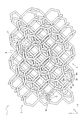
図6〜図8では、シートパッド302を構成する多孔質構造体1のうち、略直方体の外形状を有する一部分を、それぞれ別々の角度から観ている。図6は、多孔質構造体1の当該部分を示す、斜視図である。図7は、図6の多孔質構造体1の当該部分をA矢印の方向(Y方向)から観た様子を示すA矢視図である。図8は、図6の多孔質構造体1の当該部分をB矢印の方向(−Z方向)から観た様子を示すB矢視図である。
First, an example of the porous structure 1 will be described with reference to FIGS. 6 to 9.
In FIGS. 6 to 8, a part of the porous structure 1 constituting the seat pad 302 having a substantially rectangular parallelepiped outer shape is viewed from different angles. FIG. 6 is a perspective view showing the portion of the porous structure 1. FIG. 7 is a view on arrow A showing a state in which the portion of the porous structure 1 of FIG. 6 is viewed from the direction of arrow A (direction Y). FIG. 8 is a B arrow view showing a state in which the portion of the porous structure 1 of FIG. 6 is viewed from the direction of the B arrow (−Z direction).

上述したように、多孔質構造体1は、3Dプリンタによって造形されたものである。多孔質構造体1は、その全体が一体に構成されている。
多孔質構造体1は、可撓性のある樹脂又はゴムから構成されている。より具体的に、多孔質構造体1は、多孔質構造体1の骨格をなす骨格部2を備えている。骨格部2は、多数のセル孔Cを区画している。骨格部2は、多孔質構造体1のほぼ全体にわたって存在しており、可撓性のある樹脂又はゴムから構成されている。本例において、多孔質構造体1のうち、骨格部2以外の部分は、空隙であり、言い換えれば、多孔質構造体1は、骨格部2のみからなる。
As described above, the porous structure 1 is formed by a 3D printer. The entire porous structure 1 is integrally formed.
The porous structure 1 is made of a flexible resin or rubber. More specifically, the porous structure 1 includes a skeleton portion 2 that forms the skeleton of the porous structure 1. The skeleton portion 2 partitions a large number of cell holes C. The skeleton portion 2 exists almost entirely over the porous structure 1 and is made of a flexible resin or rubber. In this example, the portion of the porous structure 1 other than the skeleton portion 2 is a void, in other words, the porous structure 1 is composed of only the skeleton portion 2.

図6〜図8に示すように、多孔質構造体1の骨格部2は、複数の骨部2Bと、複数の結合部2Jと、から構成されており、骨格部2の全体が一体に構成されている。本例において、各骨部2Bは、それぞれ柱状に構成されており、また、本例では、それぞれ直線状に延在している。各結合部2Jは、それぞれ、互いに異なる方向に延在する複数(例えば、4つ)の骨部2Bの延在方向の端部2Beどうしが互いに隣接する箇所で、これらの端部2Beどうしを結合している。
図6〜図8には、多孔質構造体1の一部分に、骨格部2の骨格線Oを1点鎖線により示している。骨格部2の骨格線Oは、各骨部2Bの骨格線Oと、各結合部2Jの骨格線Oと、からなる。骨部2Bの骨格線Oは、骨部2Bの中心軸線である。結合部2Jの骨格線Oは、当該結合部2Jに結合された各骨部2Bの中心軸線をそれぞれ当該結合部2J内へ滑らかに延長させて互いに連結させてなる、延長線部分である。
骨部2Bの延在方向は、骨部2Bの骨格線O(骨格線Oのうち、骨部2Bに対応する部分。以下同じ。)の延在方向である。
多孔質構造体1は、そのほぼ全体にわたって骨格部2を備えているので、通気性を確保しつつ、外力の付加・解除に応じた圧縮・復元変形が可能であるので、クッション材(ひいてはシートパッド)としての特性が良好になる。また、多孔質構造体1の構造がシンプルになり、3Dプリンタによる造形がしやすくなる。
なお、骨格部2を構成する各骨部2Bのうち、一部又は全部の骨部2Bが、湾曲しながら延在してもよい。この場合、一部又は全部の骨部2Bが湾曲していることで、荷重の入力時において、骨部2Bひいては多孔質構造体1の急激な形状変化を防ぎ、局所的な座屈を抑制することができる。
As shown in FIGS. 6 to 8, the skeleton portion 2 of the porous structure 1 is composed of a plurality of bone portions 2B and a plurality of connecting portions 2J, and the entire skeleton portion 2 is integrally formed. Has been done. In this example, each bone portion 2B is formed in a columnar shape, and in this example, each bone portion 2B extends linearly. Each connecting portion 2J joins these end portions 2B to each other at a position where the extending direction end portions 2Be of a plurality of (for example, four) bone portions 2B extending in different directions are adjacent to each other. are doing.
6 to 8 show the skeleton line O of the skeleton portion 2 by a alternate long and short dash line in a part of the porous structure 1. The skeleton line O of the skeleton portion 2 is composed of the skeleton line O of each bone portion 2B and the skeleton line O of each connecting portion 2J. The skeleton line O of the bone portion 2B is the central axis of the bone portion 2B. The skeleton line O of the connecting portion 2J is an extension line portion formed by smoothly extending the central axis of each bone portion 2B connected to the connecting portion 2J into the connecting portion 2J and connecting them to each other.
The extending direction of the bone portion 2B is the extending direction of the skeleton line O of the bone portion 2B (the portion of the skeleton line O corresponding to the bone portion 2B; the same applies hereinafter).
Since the porous structure 1 includes the skeleton portion 2 almost entirely thereof, it can be compressed / restored and deformed according to the addition / release of an external force while ensuring breathability, so that the cushioning material (and thus the sheet) The characteristics as a pad) are improved. In addition, the structure of the porous structure 1 becomes simple, and it becomes easy to model with a 3D printer.
Of the bone portions 2B constituting the skeleton portion 2, a part or all of the bone portions 2B may extend while being curved. In this case, since part or all of the bone portion 2B is curved, it is possible to prevent a sudden shape change of the bone portion 2B and thus the porous structure 1 at the time of inputting a load, and suppress local buckling. be able to.

本例では、骨格部2を構成する各骨部2Bが、それぞれほぼ同じ形状及び長さを有している。ただし、本例に限らず、骨格部2を構成する各骨部2Bの形状及び/又は長さは、それぞれ同じでなくてもよく、例えば、一部の骨部2Bの形状及び/又は長さが他の骨部2Bとは異なっていてもよい。この場合、骨格部2のうちの特定の部分の骨部2Bの形状及び/又は長さを他の部分とは異ならせることで、意図的に異なる機械特性を得ることができる。 In this example, each bone portion 2B constituting the skeleton portion 2 has substantially the same shape and length. However, not limited to this example, the shape and / or length of each bone portion 2B constituting the skeleton portion 2 does not have to be the same, for example, the shape and / or length of a part of the bone portion 2B. May be different from other bones 2B. In this case, by making the shape and / or length of the bone portion 2B of the specific portion of the skeleton portion 2 different from that of the other portions, it is possible to intentionally obtain different mechanical properties.

本例において、各骨部2Bの幅W0(図6)及び断面積は、骨部2Bの全長にわたって一定である(すなわち、骨部2Bの延在方向に沿って均一である)。
ここで、骨部2Bの断面積は、骨部2Bの骨格線Oに垂直な断面の断面積を指す。また、骨部2Bの幅W0(図6)は、骨部2Bの骨格線Oに垂直な断面に沿って測ったときの、当該断面における最大幅を指す。
ただし、本明細書で説明する各例において、骨格部2を構成する各骨部2Bのうち一部又は全部の骨部2Bは、それぞれ、骨部2Bの幅W0及び/又は断面積が、骨部2Bの延在方向に沿って不均一でもよい。例えば、骨格部2を構成する各骨部2Bのうち一部又は全部の骨部2Bは、それぞれ、骨部2Bの延在方向の両側の端部2Beを含む部分において、骨部2Bの幅W0が、骨部2Bの延在方向の両端に向かうにつれて徐々に増大又は減少していてもよい。また、骨格部2を構成する各骨部2Bのうち一部又は全部の骨部2Bは、それぞれ、骨部2Bの延在方向の両側の端部2Beを含む部分において、骨部2Bの断面積が、骨部2Bの延在方向の両端に向かうにつれて徐々に増大又は減少していてもよい。
In this example, the width W0 (FIG. 6) and the cross-sectional area of each bone 2B are constant over the entire length of the bone 2B (that is, uniform along the extending direction of the bone 2B).
Here, the cross-sectional area of the bone portion 2B refers to the cross-sectional area of the cross section perpendicular to the skeleton line O of the bone portion 2B. Further, the width W0 (FIG. 6) of the bone portion 2B refers to the maximum width in the cross section measured along the cross section perpendicular to the skeleton line O of the bone portion 2B.
However, in each example described in the present specification, a part or all of the bone parts 2B constituting the skeleton part 2 have a width W0 and / or a cross-sectional area of the bone part 2B, respectively. It may be non-uniform along the extending direction of the portion 2B. For example, a part or all of the bone parts 2B constituting the skeleton part 2 have a width W0 of the bone part 2B in a portion including both end portions 2Be in the extending direction of the bone part 2B. However, it may gradually increase or decrease toward both ends in the extending direction of the bone portion 2B. Further, a part or all of the bone parts 2B constituting the skeleton part 2 are the cross-sectional areas of the bone parts 2B in the portion including the end portions 2Be on both sides in the extending direction of the bone part 2B, respectively. However, it may gradually increase or decrease toward both ends in the extending direction of the bone portion 2B.

本明細書で説明する各例において、骨格部2の構造の簡単化、ひいては、3Dプリンタによる多孔質構造体1の製造のし易さの観点からは、骨部2Bの幅W0(図6)は、0.05mm以上であると好適であり、0.10mm以上であるとより好適である。幅W0が0.05mm以上の場合、高性能な3Dプリンタの解像度で造形可能であり、0.10mm以上の場合、高性能な3Dプリンタだけでなく汎用の3Dプリンタの解像度でも造形可能である。
一方、骨格部2の外縁(外輪郭)形状の精度を向上させる観点や、セル孔C間の隙間(間隔)を小さくする観点や、クッション材としての特性を良好にする観点からは、骨部2Bの幅W0は、2.0mm以下であると好適である。
なお、骨格部2を構成する各骨部2Bがこの構成を満たしていると好適であるが、骨格部2を構成する各骨部2Bのうち一部の骨部2Bのみが、この構成を満たしていてもよく、その場合でも、程度の差はあり得るものの、同様の効果が得られる。
In each of the examples described in the present specification, the width W0 of the bone portion 2B (FIG. 6) is considered from the viewpoint of simplification of the structure of the skeleton portion 2 and the ease of manufacturing the porous structure 1 by the 3D printer. Is more preferably 0.05 mm or more, and more preferably 0.10 mm or more. When the width W0 is 0.05 mm or more, modeling is possible with the resolution of a high-performance 3D printer, and when the width W0 is 0.10 mm or more, modeling is possible not only with the resolution of a high-performance 3D printer but also with the resolution of a general-purpose 3D printer.
On the other hand, from the viewpoint of improving the accuracy of the outer edge (outer contour) shape of the skeleton portion 2, reducing the gap (interval) between the cell holes C, and improving the characteristics as a cushioning material, the bone portion The width W0 of 2B is preferably 2.0 mm or less.
It is preferable that each bone portion 2B constituting the skeleton portion 2 satisfies this configuration, but only a part of the bone portions 2B constituting the skeleton portion 2 satisfies this configuration. In that case, the same effect can be obtained, although the degree may vary.

本例において、骨格部2を構成する各骨部2Bは、それぞれ柱状であるとともに、それぞれの断面形状が、円形(真円形)である。
これにより、骨格部2の構造がシンプルになり、3Dプリンタによる造形がしやすくなる。また、化学反応によって発泡させる工程を経て製造された一般的なポリウレタンフォームでの機械特性を再現しやすい。よって、多孔質構造体1のクッション材としての特性を向上できる。また、このように骨部2Bを柱状に構成することにより、仮に骨部2Bを薄い膜状の部分に置き換えた場合に比べて、骨格部2の耐久性を向上できる。
なお、各骨部2Bの断面形状は、それぞれ、骨部2Bの中心軸線(骨格線O)に垂直な断面における形状である。
なお、本例に限らず、骨格部2を構成する各骨部2Bのうち一部の骨部2Bのみが、この構成を満たしていてもよく、その場合でも、程度の差はあり得るものの、同様の効果が得られる。
例えば、本明細書で説明する各例において、骨格部2を構成する各骨部2Bのうち全部又は一部の骨部2Bは、それぞれの断面形状が、多角形(正三角形、正三角形以外の三角形、四角形等)でもよいし、あるいは、真円形以外の円形(楕円形等)でもよく、その場合でも、本例と同様の効果が得られる。また、各骨部2Bは、それぞれの断面形状が、その延在方向に沿って均一でもよいし、あるいは、その延在方向に沿って非均一でもよい。また、各骨部2Bどうしで、断面形状が互いに異なっていてもよい。
In this example, each bone portion 2B constituting the skeleton portion 2 is columnar and has a circular (perfect circular) cross-sectional shape.
This simplifies the structure of the skeleton portion 2 and facilitates modeling with a 3D printer. In addition, it is easy to reproduce the mechanical properties of a general polyurethane foam produced through a process of foaming by a chemical reaction. Therefore, the characteristics of the porous structure 1 as a cushioning material can be improved. Further, by forming the bone portion 2B in a columnar shape in this way, the durability of the skeleton portion 2 can be improved as compared with the case where the bone portion 2B is replaced with a thin film-like portion.
The cross-sectional shape of each bone portion 2B is a shape in a cross section perpendicular to the central axis (skeleton line O) of the bone portion 2B.
Not limited to this example, only a part of the bones 2B constituting the skeleton 2 may satisfy this configuration, and even in that case, the degree may vary. A similar effect can be obtained.
For example, in each example described in the present specification, all or part of the bone portions 2B constituting the skeleton portion 2 have a polygonal cross-sectional shape (other than an equilateral triangle and an equilateral triangle). It may be a triangle, a quadrangle, etc.), or a circle other than a perfect circle (oval, etc.), and even in that case, the same effect as in this example can be obtained. Further, each bone portion 2B may have a uniform cross-sectional shape along the extending direction thereof, or may be non-uniform along the extending direction thereof. Further, the cross-sectional shapes of the bone portions 2B may be different from each other.

本明細書で説明する各例において、骨格部2の見かけの体積VSのうち、骨格部2の占める体積VBの割合(VB×100/VS [%])は、3〜10%であると、好適である。この構成により、骨格部2に外力が付加されたときに骨格部2に生じる反力、ひいては、骨格部2の硬さ(ひいては多孔質構造体1の硬さ)を、シートパッドとして、特には車両用のシートパッドとして、良好なものにすることができる。
ここで、「骨格部2の見かけの体積VS」とは、骨格部2の外縁(外輪郭)によって囲まれた内部空間の全体(骨格部2の占める体積と、後述の膜3(図10)が設けられる場合は膜3の占める体積と、空隙の占める体積との合計)の体積を指している。
骨格部2を構成する材料を同じとして考えたとき、骨格部2の見かけの体積VSのうち、骨格部2の占める体積VBの割合が高いほど、骨格部2(ひいては多孔質構造体1)は硬くなる。また、骨格部2の見かけの体積VSのうち、骨格部2の占める体積の割合VBが低いほど、骨格部2(ひいては多孔質構造体1)は柔らかくなる。
骨格部2に外力が付加されたときに骨格部2に生じる反力、ひいては、骨格部2(ひいては多孔質構造体1)の硬さを、シートパッドとして、特には車両用のシートパッドとして、良好なものにする観点からは、骨格部2の見かけの体積VSのうち、骨格部2の占める体積VBの割合が、4〜8%であると、より好適である。
なお、骨格部2の見かけの体積VSのうち、骨格部2の占める体積VBの割合を調整する方法としては、任意の方法を用いてよいが、例えば、骨格部2を構成する一部又は全部の骨部2Bの太さ(断面積)、及び/又は、骨格部2を構成する一部又は全部の結合部Jの大きさ(断面積)を、調整する方法が挙げられる。
In each example described in the present specification, the ratio of the volume VB occupied by the skeleton portion 2 (VB × 100 / VS [%]) to the apparent volume VS of the skeleton portion 2 is 3 to 10%. Suitable. With this configuration, the reaction force generated in the skeleton portion 2 when an external force is applied to the skeleton portion 2, and by extension, the hardness of the skeleton portion 2 (and thus the hardness of the porous structure 1) can be used as a seat pad, particularly. It can be a good seat pad for a vehicle.
Here, the "apparent volume VS of the skeleton portion 2" is the entire internal space surrounded by the outer edge (outer contour) of the skeleton portion 2 (the volume occupied by the skeleton portion 2 and the membrane 3 described later (FIG. 10)). When is provided, it refers to the volume of the volume occupied by the film 3 and the volume occupied by the voids).
When the materials constituting the skeleton portion 2 are considered to be the same, the higher the ratio of the volume VB occupied by the skeleton portion 2 to the apparent volume VS of the skeleton portion 2, the more the skeleton portion 2 (and thus the porous structure 1) becomes. It becomes hard. Further, the lower the ratio VB of the volume occupied by the skeleton portion 2 to the apparent volume VS of the skeleton portion 2, the softer the skeleton portion 2 (and thus the porous structure 1).
The reaction force generated in the skeleton portion 2 when an external force is applied to the skeleton portion 2, and the hardness of the skeleton portion 2 (and thus the porous structure 1) are used as a seat pad, particularly as a seat pad for a vehicle. From the viewpoint of making it good, it is more preferable that the ratio of the volume VB occupied by the skeleton portion 2 to the apparent volume VS of the skeleton portion 2 is 4 to 8%.
Any method may be used as a method for adjusting the ratio of the volume VB occupied by the skeleton portion 2 to the apparent volume VS of the skeleton portion 2, but for example, a part or all of the skeleton portion 2 is formed. A method of adjusting the thickness (cross-sectional area) of the bone portion 2B and / or the size (cross-sectional area) of a part or all of the connecting portions J constituting the skeleton portion 2 can be mentioned.

本明細書で説明する各例において、多孔質構造体1の25%硬度は、60〜500Nが好適であり、100〜450Nがより好適である。ここで、多孔質構造体1の25%硬度(N)は、インストロン型圧縮試験機を用いて、23℃、相対湿度50%の環境にて、多孔質構造体を25%圧縮するのに要する荷重(N)を測定して得られる測定値であるものとする。これにより、多孔質構造体1から構成されるシートパッド302の硬さを、良好なものとすることができる。 In each of the examples described herein, the 25% hardness of the porous structure 1 is preferably 60 to 500 N, more preferably 100 to 450 N. Here, the 25% hardness (N) of the porous structure 1 is such that the porous structure can be compressed by 25% in an environment of 23 ° C. and a relative humidity of 50% using an Instron type compression tester. It is assumed that the measured value is obtained by measuring the required load (N). As a result, the hardness of the seat pad 302 made of the porous structure 1 can be made good.

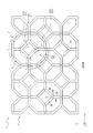
図6〜図8に示すように、本例において、骨格部2は、セル孔Cを内部に区画するセル区画部21を複数(セル孔Cの数だけ)有している。
図9は、1つのセル区画部21を単独で示している。本例の骨格部2は、多数のセル区画部21がX、Y、Zの各方向に連なった構造を有している。
図6〜図9に示すように、各セル区画部21は、それぞれ、複数(本例では、14つ)の環状部211を有している。各環状部211は、それぞれ、環状に構成されており、それぞれの環状の内周側縁部2111によって、平坦な仮想面V1を区画している。セル区画部21を構成する複数の環状部211は、それぞれの内周側縁部2111によって区画する仮想面V1どうしが交差しないように互いに連結されている。
セル孔Cは、セル区画部21を構成する複数の環状部211と、これら複数の環状部211がそれぞれ区画する複数の仮想面V1とによって、区画されている。概略的に言えば、環状部211は、セル孔Cのなす立体形状の辺を区画する部分であり、仮想面V1は、セル孔Cのなす立体形状の構成面を区画する部分である。
各環状部211は、それぞれ、複数の骨部2Bと、これらの複数の骨部2Bの端部2Beどうしを結合する複数の結合部2Jと、から構成されている。
互いに連結された一対の環状部211どうしの連結部分は、これら一対の環状部211に共有される、1つの骨部2Bと、その両側の一対の結合部2Jと、から構成されている。すなわち、各骨部2B及び各結合部2Jは、それぞれに隣接する複数の環状部211によって共有されている。
各仮想面V1は、それぞれ、仮想面V1の一方側の面(仮想面V1の表面)によって、ある1つのセル孔Cの一部を区画しているとともに、当該仮想面V1の他方側の面(仮想面V1の裏面)によって、別のセル孔Cの一部を区画している。言い換えれば、各仮想面V1は、それぞれ、その表裏両側の面によって別々のセル孔Cの一部を区画している。さらに言い換えれば、各仮想面V1は、当該仮想面V1に隣接する一対のセル孔C(すなわち、当該仮想面V1を間に挟んだ一対のセル孔C)によって共有されている。
また、各環状部211は、それぞれ、当該環状部211に隣接する一対のセル区画部21(すなわち、当該環状部211を間に挟んだ一対のセル区画部21)によって共有されている。言い換えれば、各環状部211は、それぞれ、互いに隣接する一対のセル区画部211のそれぞれの一部を構成している。
本例において、各仮想面V1は、後述の膜3(図10)によって覆われておらず、開放されており、すなわち、開口を構成している。このため、仮想面V1を通じて、セル孔Cどうしが連通され、セル孔C間の通気が、可能にされている。これにより、骨格部2の通気性を向上できるとともに、外力の付加・解除に応じた骨格部2の圧縮・復元変形がし易くなる。
As shown in FIGS. 6 to 8, in this example, the skeleton portion 2 has a plurality of cell partition portions 21 (as many as the number of cell holes C) that internally partition the cell holes C.
FIG. 9 shows one cell compartment 21 alone. The skeleton portion 2 of this example has a structure in which a large number of cell compartments 21 are connected in each of the X, Y, and Z directions.
As shown in FIGS. 6 to 9, each cell partition 21 has a plurality of (14 in this example) annular portions 211, respectively. Each of the annular portions 211 is formed in an annular shape, and the flat virtual surface V1 is partitioned by the inner peripheral side edge portions 2111 of the respective annular portions. The plurality of annular portions 211 constituting the cell partition portion 21 are connected to each other so that the virtual surfaces V1 partitioned by the inner peripheral side edge portions 2111 do not intersect with each other.
The cell hole C is partitioned by a plurality of annular portions 211 constituting the cell partition portion 21, and a plurality of virtual surfaces V1 in which the plurality of annular portions 211 are partitioned. Roughly speaking, the annular portion 211 is a portion that partitions the side of the three-dimensional shape formed by the cell hole C, and the virtual surface V1 is a portion that partitions the constituent surface of the three-dimensional shape formed by the cell hole C.
Each annular portion 211 is composed of a plurality of bone portions 2B and a plurality of connecting portions 2J for connecting the end portions 2Be of the plurality of bone portions 2B.
The connecting portion between the pair of annular portions 211 connected to each other is composed of one bone portion 2B shared by the pair of annular portions 211 and a pair of connecting portions 2J on both sides thereof. That is, each bone portion 2B and each connecting portion 2J are shared by a plurality of annular portions 211 adjacent to each other.
Each virtual surface V1 has a part of one cell hole C partitioned by one surface of the virtual surface V1 (the surface of the virtual surface V1), and the other surface of the virtual surface V1. A part of another cell hole C is partitioned by (the back surface of the virtual surface V1). In other words, each virtual surface V1 divides a part of separate cell holes C by the surfaces on both the front and back sides thereof. In other words, each virtual surface V1 is shared by a pair of cell holes C adjacent to the virtual surface V1 (that is, a pair of cell holes C sandwiching the virtual surface V1).
Further, each annular portion 211 is shared by a pair of cell compartments 21 adjacent to the annular portion 211 (that is, a pair of cell compartments 21 sandwiching the annular portion 211 in between). In other words, each annular portion 211 constitutes each part of a pair of cell compartments 211 adjacent to each other.
In this example, each virtual surface V1 is not covered by the film 3 (FIG. 10) described later and is open, that is, constitutes an opening. Therefore, the cell holes C are communicated with each other through the virtual surface V1, and ventilation between the cell holes C is possible. As a result, the air permeability of the skeleton portion 2 can be improved, and the skeleton portion 2 can be easily compressed / restored and deformed in response to the addition / release of an external force.

図9に示すように、本例において、各セル区画部21の骨格線Oは、多面体の形状をなしており、それにより、各セル孔Cが、略多面体の形状をなしている。より具体的に、図6〜図9の例において、各セル区画部21の骨格線Oは、ケルビン14面体(切頂8面体)の形状をなしており、それにより、各セル孔Cが、略ケルビン14面体(切頂8面体)の形状をなしている。ケルビン14面体(切頂8面体)は、6つの正4角形の構成面と8つの正6角形の構成面とから構成される、多面体である。骨格部2を構成するセル孔Cは、概略的に言えば、骨格部2の外縁(外輪郭)により囲まれた内部空間を空間充填するように(すなわち、各セル孔Cが無駄な隙間無く敷き詰められるように、さらに言い換えれば、セル孔C間の隙間(間隔)を小さくするように)、規則性をもって配列されている。
本例のように、骨格部2の一部または全部(本例では、全部)のセル区画部21の骨格線Oの形状(ひいては、骨格部2の一部または全部(本例では、全部)のセル孔Cの形状)を多面体とすることにより、骨格部2を構成するセル孔C間の隙間(間隔)をより小さくすることが可能になり、より多くのセル孔Cを骨格部2の内部に形成することができる。また、これにより、外力の付加・解除に応じた骨格部2(ひいては、多孔質構造体1)の圧縮・復元変形の挙動が、シートパッドとして、特には車両用のシートパッドとして、より良好になる。
セル区画部21の骨格線Oのなす多面体形状(ひいては、セル孔Cのなす多面体形状)としては、本例に限らず、任意のものが可能である。例えば、セル区画部21の骨格線Oの形状(ひいては、セル孔Cのなす形状)を略4面体、略8面体又は略12面体とした場合も、セル孔C間の隙間(間隔)を小さくする観点から好適である。また、骨格部2の一部または全部のセル区画部21の骨格線Oの形状(ひいては、骨格部2の一部または全部のセル孔Cのなす形状)は、略多面体以外の立体形状(例えば、球、楕円体、円柱等)でもよい。また、骨格部2は、セル区画部21として、骨格線Oの形状が同じである1種類のセル区画部21のみを有していてもよいし、あるいは、骨格線Oの形状が異なる複数種類のセル区画部21を有していてもよい。同様に、骨格部2は、セル孔Cとして、同じ形状からなる1種類のセル孔Cのみを有していてもよいし、あるいは、形状の異なる複数種類のセル孔Cを有していてもよい。なお、本例のように、セル区画部21の骨格線Oの形状(ひいては、セル孔Cの形状)を略ケルビン14面体(切頂8面体)とした場合は、他の形状に比べて、化学反応によって発泡させる工程を経て製造された一般的なポリウレタンフォームと同等のクッション材の特性を、最も再現し易い。
As shown in FIG. 9, in this example, the skeleton line O of each cell compartment 21 has a polyhedral shape, so that each cell hole C has a substantially polyhedral shape. More specifically, in the examples of FIGS. 6 to 9, the skeleton line O of each cell compartment 21 has the shape of a Kelvin tetradecahedron (truncated octahedron), whereby each cell hole C is formed. It has the shape of a Kelvin tetradecahedron (truncated octahedron). The Kelvin tetradecahedron (truncated octahedron) is a polyhedron composed of six regular quadrilateral constituent faces and eight regular hexagonal constituent faces. Roughly speaking, the cell holes C constituting the skeleton portion 2 fill the internal space surrounded by the outer edge (outer contour) of the skeleton portion 2 (that is, each cell hole C has no unnecessary gaps). They are arranged in a regular manner so that they can be spread out, in other words, to reduce the gap (interval) between the cell holes C).
As in this example, the shape of the skeleton line O of the cell compartment 21 of a part or all of the skeleton part 2 (all in this example) (and by extension, a part or all of the skeleton part 2 (all in this example)). By making the cell hole C (shape) of the cell hole C a polyhedron, it is possible to make the gap (interval) between the cell holes C constituting the skeleton portion 2 smaller, and to make more cell holes C of the skeleton portion 2 Can be formed inside. Further, as a result, the behavior of compression / restoration deformation of the skeleton portion 2 (and by extension, the porous structure 1) in response to the addition / release of the external force becomes better as a seat pad, particularly as a seat pad for a vehicle. Become.
The polyhedral shape formed by the skeleton line O of the cell compartment 21 (and thus the polyhedral shape formed by the cell hole C) is not limited to this example, and any shape can be used. For example, even when the shape of the skeleton line O of the cell compartment 21 (and thus the shape formed by the cell hole C) is a substantially tetrahedron, a substantially octahedron, or a substantially dodecahedron, the gap (interval) between the cell holes C is reduced. It is suitable from the viewpoint of Further, the shape of the skeleton line O of a part or all of the cell compartments 21 of the skeleton part 2 (and thus the shape formed by the cell holes C of a part or all of the skeleton part 2) is a three-dimensional shape other than a substantially polyhedron (for example). , Sphere, ellipsoid, cylinder, etc.). Further, the skeleton portion 2 may have only one type of cell partition portion 21 having the same shape of the skeleton line O as the cell partition portion 21, or a plurality of types having different shapes of the skeleton line O. May have a cell compartment 21 of. Similarly, the skeleton portion 2 may have only one type of cell hole C having the same shape as the cell hole C, or may have a plurality of types of cell holes C having different shapes. Good. When the shape of the skeleton line O of the cell compartment 21 (and by extension, the shape of the cell hole C) is substantially Kelvin tetradecahedron (truncated octahedron) as in this example, it is compared with other shapes. It is easiest to reproduce the characteristics of a cushioning material equivalent to general polyurethane foam manufactured through a process of foaming by a chemical reaction.

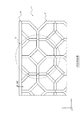
図6〜図9に示すように、本例において、セル区画部21を構成する複数(本例では、14つ)の環状部211は、それぞれ、1つ又は複数(本例では、6つ)の小環状部211Sと、1つ又は複数(本例では、8つ)の大環状部211Lと、を含んでいる。各小環状部211Sは、それぞれ、その環状の内周側縁部2111によって、小仮想面V1Sを区画している。各大環状部211Lは、それぞれ、その環状の内周側縁部2111によって、小仮想面V1Sよりも面積の大きな大仮想面V1Lを区画している。
図9から判るように、本例において、大環状部211Lは、その骨格線Oが正6角形をなしており、それに伴い、大仮想面V1Lも、略正6角形をなしている。また、本例において、小環状部211Sは、その骨格線Oが正4角形をなしており、それに伴い、小仮想面V1Sも、略正4角形をなしている。このように、本例において、小仮想面V1Sと大仮想面V1Lとは、面積だけでなく、形状も異なる。
各大環状部211Lは、それぞれ、複数(本例では、6つ)の骨部2Bと、これらの複数の骨部2Bの端部2Beどうしを結合する複数(本例では、6つ)の結合部2Jと、から構成されている。各小環状部211Sは、それぞれ、複数(本例では、4つ)の骨部2Bと、これらの複数の骨部2Bの端部2Beどうしを結合する複数(本例では、4つ)の結合部2Jと、から構成されている。
セル区画部21を構成する複数の環状部211が、大きさの異なる小環状部211Sと大環状部211Lとを含むことにより、骨格部2を構成するセル孔C間の隙間(間隔)をより小さくすることが可能になる。また、本例のように、小環状部211Sと大環状部211Lとの形状が異なる場合、骨格部2を構成するセル孔C間の隙間(間隔)をさらに小さくすることが可能になる。
ただし、セル区画部21を構成する複数の環状部211は、それぞれ、大きさ及び/又は形状が互いに同じでもよい。セル区画部21を構成する各環状部211の大きさ及び形状が同じである場合、X、Y、Zのそれぞれの方向に等しい機械特性を得ることができる。
As shown in FIGS. 6 to 9, in this example, the plurality of (14 in this example) annular portions 211 constituting the cell compartment 21 are one or a plurality (six in this example), respectively. The small annular portion 211S of the above and one or more (eight in this example) large annular portion 211L are included. Each of the small annular portions 211S divides the small virtual surface V1S by the inner peripheral side edge portion 2111 of the annular portion. Each macrocyclic portion 211L divides a large virtual surface V1L having a larger area than the small virtual surface V1S by the inner peripheral side edge portion 2111 of the annular portion.
As can be seen from FIG. 9, in this example, the skeleton line O of the macrocyclic portion 211L has a regular hexagonal shape, and the large virtual surface V1L also has a substantially regular hexagonal shape. Further, in this example, the skeleton line O of the small annular portion 211S has a regular quadrangle, and accordingly, the small virtual surface V1S also has a substantially regular quadrangle. As described above, in this example, the small virtual surface V1S and the large virtual surface V1L differ not only in area but also in shape.
Each macrocyclic portion 211L is a combination of a plurality of (six in this example) bone portions 2B and a plurality of (six in this example) bone portions 2Be for connecting the plurality of bone portions 2B. It is composed of a part 2J. Each of the small annular portions 211S is a combination of a plurality of (four in this example) bone portions 2B and a plurality of (four in this example) connecting the end portions 2Be of these plurality of bone portions 2B. It is composed of a part 2J.
By including the small annular portion 211S and the large annular portion 211L having different sizes, the plurality of annular portions 211 constituting the cell partition portion 21 increase the gap (interval) between the cell holes C constituting the skeleton portion 2. It becomes possible to make it smaller. Further, when the shapes of the small annular portion 211S and the large annular portion 211L are different as in this example, the gap (interval) between the cell holes C constituting the skeleton portion 2 can be further reduced.
However, the plurality of annular portions 211 constituting the cell partition portion 21 may have the same size and / or shape, respectively. When the size and shape of each annular portion 211 constituting the cell partition portion 21 are the same, mechanical characteristics equal to each of the directions of X, Y, and Z can be obtained.

本例のように、セル区画部21を構成する各環状部211のうち、一部又は全部(本例では全部)の環状部211の骨格線O(ひいては、セル区画部21を構成する各仮想面V1のうち、一部又は全部(本例では全部)の仮想面V1)が、略多角形状をなすことにより、骨格部2を構成するセル孔Cどうしの間隔をより小さくすることが可能になる。また、外力の付加・解除に応じた骨格部2の圧縮・復元変形の挙動が、シートパッドとして、特には車両用のシートパッドとして、より良好になる。また、環状部211の形状(ひいては仮想面V1の形状)がシンプルになるので、製造性や特性の調整のし易さを向上できる。なお、骨格部2を構成する各環状部211のうち、少なくとも1つの環状部211(ひいては、骨格部2を構成する各仮想面V1のうち、少なくとも1つの仮想面V1)が、この構成を満たしている場合は、程度の差はあり得るものの、同様の効果が得られる。
なお、骨格部2を構成する各環状部211のうち、少なくとも1つの環状部211の骨格線O(ひいては、骨格部2を構成する各仮想面V1のうち、少なくとも1つの仮想面V1)が、本例のような略正6角形、略正4角形以外の任意の略多角形状、あるいは、略多角形状以外の平面形状(例えば、円(真円、楕円等))をなしてもよい。環状部211の骨格線Oの形状(ひいては仮想面V1の形状)が円(真円、楕円等)である場合は、環状部211の形状(ひいては仮想面V1の形状)がシンプルになるので、製造性や特性の調整のし易さを向上できるとともに、より均質な機械特性が得られる。例えば、環状部211の骨格線Oの形状(ひいては仮想面V1の形状)が、荷重が掛かる方向に対して略垂直な方向に長い楕円(横長の楕円)である場合は、荷重が掛かる方向に略平行な方向に長い楕円(縦長の楕円)である場合に比べて、環状部211が、ひいては、骨格部2(ひいては多孔質構造体1)が、荷重の入力に対して変形し易くなる(柔らかくなる)。
As in this example, of each annular portion 211 constituting the cell partition portion 21, the skeleton line O of a part or all (all in this example) of the annular portion 211 (by extension, each virtual portion constituting the cell partition portion 21). The virtual surface V1) of a part or all (all in this example) of the surface V1 has a substantially polygonal shape, so that the distance between the cell holes C constituting the skeleton portion 2 can be made smaller. Become. Further, the behavior of compression / restoration deformation of the skeleton portion 2 in response to the addition / release of an external force becomes better as a seat pad, particularly as a seat pad for a vehicle. Further, since the shape of the annular portion 211 (and thus the shape of the virtual surface V1) is simplified, the manufacturability and the ease of adjusting the characteristics can be improved. It should be noted that at least one annular portion 211 (by extension, at least one virtual surface V1 among each virtual surface V1 constituting the skeleton portion 2) of each annular portion 211 constituting the skeleton portion 2 satisfies this configuration. If so, the same effect can be obtained, although the degree may vary.
The skeleton line O of at least one annular portion 211 among the annular portions 211 constituting the skeleton portion 2 (and by extension, at least one virtual plane V1 among the virtual planes V1 constituting the skeleton portion 2) is Any substantially polygonal shape other than the substantially regular hexagon and the substantially regular quadrangle as in this example, or a plane shape other than the substantially regular polygon shape (for example, a circle (perfect circle, ellipse, etc.)) may be formed. When the shape of the skeleton line O of the annular portion 211 (and thus the shape of the virtual surface V1) is a circle (a perfect circle, an ellipse, etc.), the shape of the annular portion 211 (and thus the shape of the virtual surface V1) becomes simple. Manufacturability and ease of adjusting characteristics can be improved, and more uniform mechanical characteristics can be obtained. For example, when the shape of the skeleton line O of the annular portion 211 (and thus the shape of the virtual surface V1) is a long ellipse (horizontally long ellipse) substantially perpendicular to the direction in which the load is applied, the direction in which the load is applied Compared to the case where the ellipse is long in a substantially parallel direction (longitudinal ellipse), the annular portion 211 and, by extension, the skeleton portion 2 (and thus the porous structure 1) are more likely to be deformed with respect to the input of a load ( It becomes soft).

本例において、骨格部2は、直径が5mm以上のセル孔Cを少なくとも1つ有すると、好適である。これにより、3Dプリンタを用いた多孔質構造体1の製造が実現し易くなる。骨格部2の各セル孔Cの直径が5mm未満であると、骨格部2の構造が複雑になりすぎる結果、多孔質構造体1の3次元形状を表す3次元形状データ(CADデータ等)、あるいは、その3次元形状データに基づき生成される3D造形用データを、コンピュータ上で生成するのが難しくなるおそれがある。
なお、従来のシートパッドを構成する多孔質構造体は、化学反応によって発泡させる工程を経て製造されていたため、直径が5mm以上のセル孔Cを形成することはできなかった。
また、骨格部2が直径5mm以上のセル孔Cを有することにより、骨格部2の通気性や変形し易さを向上しやすくなる。
このような観点から、骨格部2を構成する全てのセル孔Cの直径が、それぞれ、5mm以上であると、好適である。
セル孔Cの直径が大きくなるほど、3Dプリンタを用いた多孔質構造体1(ひいてはシートパッド302)の製造が実現し易くなり、また、通気性や変形し易さを向上しやすくなる。このような観点から、骨格部2は、少なくとも1つ(好適には全部)のセル孔Cの直径が、より好適には8mm以上、さらに好適には10mm以上であるとよい。
一方、骨格部2のセル孔Cが大きすぎると、骨格部2(ひいては多孔質構造体1)の外縁(外輪郭)形状をきれいに(滑らかに)形成するのが難しくなり、シートパッド302の形状精度が低下し外観が悪化するおそれがある。また、シートパッドとしての特性も、十分に良好でなくなるおそれがある。よって、外観やシートパッドとしての特性を向上させる観点から、骨格部2の各セル孔Cの直径は、好適には30mm未満、より好適には25mm以下、さらに好適には20mm以下であるとよい。
なお、セル孔Cの直径は、本例のようにセル孔Cが厳密な球形状とは異なる形状をなす場合、セル孔Cの外接球の直径を指す。
In this example, it is preferable that the skeleton portion 2 has at least one cell hole C having a diameter of 5 mm or more. This facilitates the production of the porous structure 1 using a 3D printer. If the diameter of each cell hole C of the skeleton portion 2 is less than 5 mm, the structure of the skeleton portion 2 becomes too complicated, and as a result, three-dimensional shape data (CAD data, etc.) representing the three-dimensional shape of the porous structure 1 Alternatively, it may be difficult to generate 3D modeling data generated based on the three-dimensional shape data on a computer.
Since the porous structure constituting the conventional seat pad was manufactured through a step of foaming by a chemical reaction, it was not possible to form a cell hole C having a diameter of 5 mm or more.
Further, since the skeleton portion 2 has the cell hole C having a diameter of 5 mm or more, it becomes easy to improve the air permeability and the easiness of deformation of the skeleton portion 2.
From this point of view, it is preferable that the diameters of all the cell holes C constituting the skeleton portion 2 are 5 mm or more, respectively.
The larger the diameter of the cell hole C, the easier it is to manufacture the porous structure 1 (and thus the seat pad 302) using a 3D printer, and it becomes easier to improve the air permeability and the easiness of deformation. From such a viewpoint, the diameter of at least one (preferably all) cell holes C in the skeleton portion 2 is more preferably 8 mm or more, still more preferably 10 mm or more.
On the other hand, if the cell hole C of the skeleton portion 2 is too large, it becomes difficult to form the outer edge (outer contour) shape of the skeleton portion 2 (and by extension, the porous structure 1) neatly (smoothly), and the shape of the seat pad 302. The accuracy may decrease and the appearance may deteriorate. In addition, the characteristics of the seat pad may not be sufficiently good. Therefore, from the viewpoint of improving the appearance and the characteristics as a seat pad, the diameter of each cell hole C of the skeleton portion 2 is preferably less than 30 mm, more preferably 25 mm or less, and further preferably 20 mm or less. ..
The diameter of the cell hole C refers to the diameter of the circumscribed sphere of the cell hole C when the cell hole C has a shape different from the exact spherical shape as in this example.

骨格部2のセル孔Cが小さすぎると、骨格部2の構造が複雑になりすぎる結果、多孔質構造体1の3次元形状を表す3次元形状データ(CADデータ等)、あるいは、その3次元形状データに基づき生成される3D造形用データを、コンピュータ上で生成するのが難しくなるおそれや、仮にそれらを生成できたとしても、その3D造形用データに従って3Dプリンタが造形するのが難しくなるおそれがあるため、3Dプリンタを用いた多孔質構造体1の製造がしにくくなる。3Dプリンタを用いた多孔質構造体1(ひいてはシートパッド302)の製造を容易にする観点から、骨格部2を構成する各セル孔Cのうち、最小の直径を有するセル孔Cの直径が、0.05mm以上であると好適であり、0.10mm以上であるとより好適である。最小の直径を有するセル孔Cの直径が、0.05mm以上の場合、高性能な3Dプリンタの解像度で造形可能であり、0.10mm以上の場合、高性能な3Dプリンタだけでなく汎用の3Dプリンタの解像度でも造形可能である。 If the cell hole C of the skeleton portion 2 is too small, the structure of the skeleton portion 2 becomes too complicated, and as a result, three-dimensional shape data (CAD data or the like) representing the three-dimensional shape of the porous structure 1 or its three-dimensional shape. There is a risk that it will be difficult to generate 3D modeling data generated based on the shape data on a computer, and even if they can be generated, it may be difficult for a 3D printer to model according to the 3D modeling data. Therefore, it becomes difficult to manufacture the porous structure 1 using a 3D printer. From the viewpoint of facilitating the production of the porous structure 1 (and thus the seat pad 302) using a 3D printer, the diameter of the cell hole C having the smallest diameter among the cell holes C constituting the skeleton portion 2 is set. It is preferably 0.05 mm or more, and more preferably 0.10 mm or more. When the diameter of the cell hole C having the minimum diameter is 0.05 mm or more, it is possible to model with the resolution of a high-performance 3D printer, and when it is 0.10 mm or more, not only a high-performance 3D printer but also a general-purpose 3D It can also be modeled at the resolution of the printer.

図10は、多孔質構造体1のセル区画部21の一変形例を説明するための図面であり、図9に対応する図面である。本明細書で説明する各例において、多孔質構造体1は、図10に示す変形例のように、骨格部2に加えて、1つ又は複数の膜3を備えていてもよい。
膜3は、環状部211の環状の内周側縁部2111によって区画された仮想面V1上を延在しており、それにより、当該環状部211によって区画された仮想面V1を覆っている。図10の例の多孔質構造体1においては、骨格部2を構成する各仮想面V1のうちの少なくとも1つが、膜3で覆われている。膜3は、骨格部2と同じ材料からなり、骨格部2と一体に構成されている。図10の例において、膜3は、平坦に構成されている。ただし、膜3は、非平坦(例えば、湾曲状(曲面状))に構成されてもよい。
膜3は、骨部2Bの幅W0(図6)よりも小さな厚さを有すると、好適である。
膜3によって、仮想面V1を間に挟んだ2つのセル孔Cどうしが、仮想面V1を通じた連通がなくなり、仮想面V1を介した通気ができなくなるため、ひいては、多孔質構造体1の全体としての通気性が低下する。多孔質構造体1を構成する各仮想面V1のうち、膜3で覆われたものの数を調整することにより、多孔質構造体1の全体としての通気性を調整でき、要求に応じて様々な通気性レベルを実現可能である。例えば、多孔質構造体1が車両用シートパッドに利用される場合、多孔質構造体1の通気性を調整することにより、車内のエアコンの効きを高めたり、耐ムレ性を高めたり、乗り心地を高めることができる。多孔質構造体1が車両用シートパッドに利用される場合、車内のエアコンの効き及び耐ムレ性を高めるとともに、乗り心地を高める観点からは、多孔質構造体1を構成する各仮想面V1の全てが膜3で覆われているのは好ましくなく、言い換えれば、多孔質構造体1を構成する各仮想面V1のうち少なくとも1つが膜3で覆われておらず開放されていることが好ましい。
なお、従来のシートパッドを構成する多孔質構造体は、上述のとおり、化学反応によって発泡させる工程を経て製造されていたため、各セルどうしを連通する連通孔における膜を、所期したとおりの位置及び個数で形成することは難しかった。本例のように、多孔質構造体1(ひいてはシートパッド302)を3Dプリンタで製造する場合は、3Dプリンタに読み込まれる3D造形用データに、予め膜3の情報も含めることで、確実に、所期したとおりの位置及び個数で膜3を形成することが可能である。
同様の観点から、骨格部2を構成する各小仮想面V1Sのうちの少なくとも1つが、膜3で覆われていてもよい。かつ/又は、骨格部2を構成する各大仮想面V1Lのうちの少なくとも1つが、膜3で覆われていてもよい。
FIG. 10 is a drawing for explaining a modification of the cell compartment 21 of the porous structure 1, and is a drawing corresponding to FIG. 9. In each of the examples described herein, the porous structure 1 may include one or more membranes 3 in addition to the skeleton portion 2, as in the modified example shown in FIG.
The film 3 extends over the virtual surface V1 partitioned by the annular inner peripheral edge 2111 of the annular portion 211, thereby covering the virtual surface V1 partitioned by the annular portion 211. In the porous structure 1 of the example of FIG. 10, at least one of the virtual surfaces V1 constituting the skeleton portion 2 is covered with the film 3. The film 3 is made of the same material as the skeleton portion 2 and is integrally formed with the skeleton portion 2. In the example of FIG. 10, the film 3 is formed flat. However, the film 3 may be configured to be non-flat (for example, curved (curved)).
It is preferable that the membrane 3 has a thickness smaller than the width W0 (FIG. 6) of the bone portion 2B.
Due to the membrane 3, the two cell holes C sandwiching the virtual surface V1 are not communicated with each other through the virtual surface V1 and cannot be ventilated through the virtual surface V1. Therefore, the entire porous structure 1 is formed. As the air permeability is reduced. By adjusting the number of virtual surfaces V1 constituting the porous structure 1 that are covered with the membrane 3, the overall air permeability of the porous structure 1 can be adjusted, and various types can be obtained as required. Breathability levels can be achieved. For example, when the porous structure 1 is used for a vehicle seat pad, the effectiveness of the air conditioner in the vehicle can be enhanced, the stuffiness resistance can be enhanced, and the riding comfort can be improved by adjusting the air permeability of the porous structure 1. Can be enhanced. When the porous structure 1 is used for a vehicle seat pad, from the viewpoint of enhancing the effectiveness and stuffiness resistance of the air conditioner in the vehicle and improving the riding comfort, each virtual surface V1 constituting the porous structure 1 It is not preferable that all of them are covered with the membrane 3, in other words, it is preferable that at least one of the virtual surfaces V1 constituting the porous structure 1 is not covered with the membrane 3 and is open.
Since the porous structure constituting the conventional seat pad was manufactured through the step of foaming by a chemical reaction as described above, the position of the membrane in the communication hole communicating the cells with each other is as expected. And it was difficult to form by number. When the porous structure 1 (and thus the seat pad 302) is manufactured by a 3D printer as in this example, the information of the film 3 is surely included in the 3D modeling data read by the 3D printer in advance. It is possible to form the film 3 at the desired position and number.
From the same viewpoint, at least one of the small virtual surfaces V1S constituting the skeleton portion 2 may be covered with the film 3. And / or at least one of the large virtual surfaces V1L constituting the skeleton portion 2 may be covered with the film 3.

本明細書で説明する各例において、多孔質構造体1が車両用シートパッドに利用される場合、車内のエアコンの効き及び耐ムレ性を高めたり、乗り心地を高める観点からは、多孔質構造体1の通気性は、100〜700cc/cm2/secが好適であり、150〜650cc/cm2/secがより好適であり、200〜600cc/cm2/secがさらに好適である。ここで、多孔質構造体1の通気性(cc/cm2/sec)は、JIS K 6400-7に準拠して測定されるものとする。また、多孔質構造体1が車両用シートパッドに利用される場合、多孔質構造体1の共振倍率は、3倍以上8倍未満が好適であり、3倍以上5倍以下がより好適である。 In each example described in the present specification, when the porous structure 1 is used for a vehicle seat pad, the porous structure is improved from the viewpoint of enhancing the effectiveness and stuffiness resistance of the air conditioner in the vehicle and enhancing the riding comfort. breathable body 1 is suitably 100~700cc / cm 2 / sec, 150~650cc / cm 2 / sec is more preferred, it is further preferable that 200~600cc / cm 2 / sec. Here, the air permeability (cc / cm 2 / sec) of the porous structure 1 shall be measured in accordance with JIS K 6400-7. When the porous structure 1 is used for a vehicle seat pad, the resonance magnification of the porous structure 1 is preferably 3 times or more and less than 8 times, and more preferably 3 times or more and 5 times or less. ..

〔シートパッドの製造方法、3D造形用データ〕
つぎに、図11を参照しつつ、本発明のシートパッドの製造方法を例示説明する。以下に説明する方法は、本明細書で説明する任意の例のシートパッドを製造するために好適に用いることができる。
まず、事前に、コンピュータを用いて、多孔質構造体1から構成されたシートパッド302の3次元形状を表す3次元形状データ(例えば、3次元CADデータ)を作成する。
つぎに、コンピュータを用いて、上記3次元形状データを、3D造形用データ500に変換する。3D造形用データ500は、3Dプリンタ400の造形部420が造形を行う際に3Dプリンタ400の制御部410に読み込まれるものであり、制御部410が、造形部420に、シートパッド302を、造形させるように構成されている。3D造形用データ500は、例えば、シートパッド302の各層の2次元形状を表すスライスデータを含む。
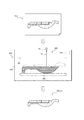
つぎに、3Dプリンタ400によってシートパッド302の造形を行う。3Dプリンタ400は、例えば、光造形方式、粉末焼結積層方式、熱溶融積層方式(FDM方式)、インクジェット方式等、任意の造形方式を用いて造形を行ってよい。生産性の観点からは、光造形方式が好適である。図11では、光造形方式によって造形を行う様子を示している。
3Dプリンタ400は、例えば、CPU等によって構成された制御部410と、制御部410による制御に従って造形を行う造形部420と、造形される造形物(すなわち、シートパッド302)を載せるための支持台430と、液体樹脂LR、支持台430及び造形物が収容される収容体440と、を備える。造形部420は、本例のように光造形方式を用いる場合、紫外線レーザ光LLを照射するように構成されたレーザ照射器421を有する。収容体440には、液体樹脂LRが充填されている。液体樹脂LRは、レーザ照射器421から照射される紫外線レーザ光LLが当たると、硬化し、可撓性のある樹脂となる。
このように構成された3Dプリンタ400は、まず、制御部410が、3D造形用データ500を読み込み、読み込んだ3D造形用データ500に含まれる3次元形状に基づいて、造形部420に紫外線レーザ光LLを照射するよう制御しながら、各層を順次造形していく(造形ステップ)。
3Dプリンタ400による造形が完了した後は、造形物を収容体440から取り出す。それにより、最終的に、造形物として、多孔質構造体1から構成されたシートパッド302が得られる。
3Dプリンタを用いてシートパッド302を製造することにより、流体通路5を有するシートパッド302を、1つの工程で、簡単かつ精度良く、所期したとおりに実現できる。
なお、シートパッド302を樹脂で構成する場合、3Dプリンタ400による造形が完了した後に、造形物としてのシートパッド302を、オーブンの中で加熱してもよい。その場合、シートパッド302を構成する各層どうしの結合を強化し、それによりシートパッド302の異方性を低減できるので、シートパッド302のクッション性をさらに向上できる。
また、シートパッド302をゴムで構成する場合、3Dプリンタ400による造形が完了した後に、造形物としてのシートパッド302を加硫してもよい。
[Seat pad manufacturing method, 3D modeling data]
Next, the method for manufacturing the seat pad of the present invention will be illustrated with reference to FIG. The methods described below can be suitably used for producing the seat pads of any of the examples described herein.
First, in advance, a computer is used to create three-dimensional shape data (for example, three-dimensional CAD data) representing the three-dimensional shape of the seat pad 302 composed of the porous structure 1.
Next, the above three-dimensional shape data is converted into 3D modeling data 500 using a computer. The 3D modeling data 500 is read by the control unit 410 of the 3D printer 400 when the modeling unit 420 of the 3D printer 400 performs modeling, and the control unit 410 models the seat pad 302 on the modeling unit 420. It is configured to let you. The 3D modeling data 500 includes, for example, slice data representing the two-dimensional shape of each layer of the seat pad 302.
Next, the seat pad 302 is modeled by the 3D printer 400. The 3D printer 400 may perform modeling using any modeling method such as a stereolithography method, a powder sintering lamination method, a hot melt lamination method (FDM method), or an inkjet method. From the viewpoint of productivity, the stereolithography method is preferable. FIG. 11 shows a state in which modeling is performed by a stereolithography method.
The 3D printer 400 is, for example, a support base for mounting a control unit 410 configured by a CPU or the like, a modeling unit 420 that performs modeling according to control by the control unit 410, and a modeled object (that is, a seat pad 302) to be modeled. It includes a 430, a liquid resin LR, a support 430, and an accommodating body 440 in which a modeled object is housed. The modeling unit 420 has a laser irradiator 421 configured to irradiate an ultraviolet laser beam LL when a stereolithography method is used as in this example. The housing 440 is filled with a liquid resin LR. When the liquid resin LR is exposed to the ultraviolet laser light LL emitted from the laser irradiator 421, the liquid resin LR is cured and becomes a flexible resin.
In the 3D printer 400 configured in this way, first, the control unit 410 reads the 3D modeling data 500, and based on the three-dimensional shape included in the read 3D modeling data 500, the modeling unit 420 receives an ultraviolet laser beam. While controlling to irradiate LL, each layer is sequentially modeled (modeling step).
After the modeling by the 3D printer 400 is completed, the modeled object is taken out from the housing 440. As a result, the seat pad 302 made of the porous structure 1 is finally obtained as a modeled object.
By manufacturing the seat pad 302 using a 3D printer, the seat pad 302 having the fluid passage 5 can be realized easily, accurately, and as expected in one step.
When the seat pad 302 is made of resin, the seat pad 302 as a modeled object may be heated in an oven after the modeling by the 3D printer 400 is completed. In that case, the coupling between the layers constituting the seat pad 302 is strengthened, whereby the anisotropy of the seat pad 302 can be reduced, so that the cushioning property of the seat pad 302 can be further improved.
Further, when the seat pad 302 is made of rubber, the seat pad 302 as a modeled object may be vulcanized after the modeling by the 3D printer 400 is completed.

〔第2実施形態に係るシートパッド〕
つぎに、図12及び図13を参照しつつ、本発明の第2実施形態に係るシートパッド302について、第1実施形態とは異なる点を中心に、説明する。
図12は、本発明の第2実施形態に係るシートパッド302の一例から構成されたクッションパッド310を、図2のI−I線に沿う断面により示す、前後方向(延在方向)断面図であり、図3に対応する図面である。図13は、本発明の第2実施形態に係るシートパッド302の一例から構成されたバックパッド320を、図4のK−K線に沿う断面により示す、延在方向断面図であり、図5に対応する図面である。
以下では、説明の便宜のため、第2実施形態に係るシートパッド302からなるクッションパッド310及びバックパッド320について、併せて説明する。
第2実施形態においては、シートパッド302のうち流体通路近傍部分7Aを構成する多孔質構造体1の構成が、シートパッド302のうち流体通路近傍部分以外の部分7Bを構成する多孔質構造体1の構成とは、異なるものである。流体通路近傍部分7Aは、シートパッド302のうち、流体通路5の全体を区画する部分を含む一部分である。
第2実施形態において、流体通路5自体の構成は、第1実施形態で述べたとおりでよい。
[Seat pad according to the second embodiment]
Next, with reference to FIGS. 12 and 13, the seat pad 302 according to the second embodiment of the present invention will be described focusing on the points different from those of the first embodiment.
FIG. 12 is a cross-sectional view in the front-rear direction (extending direction) showing a cushion pad 310 composed of an example of the seat pad 302 according to the second embodiment of the present invention by a cross section along the line I-I of FIG. Yes, it is a drawing corresponding to FIG. FIG. 13 is a cross-sectional view in the extending direction showing a back pad 320 composed of an example of the seat pad 302 according to the second embodiment of the present invention with a cross section taken along the line KK of FIG. It is a drawing corresponding to.
Hereinafter, for convenience of explanation, the cushion pad 310 and the back pad 320 including the seat pad 302 according to the second embodiment will be described together.
In the second embodiment, the structure of the porous structure 1 constituting the fluid passage vicinity portion 7A of the seat pad 302 constitutes the porous structure 1 of the seat pad 302 other than the fluid passage vicinity portion 7B. It is different from the configuration of. The fluid passage vicinity portion 7A is a portion of the seat pad 302 including a portion that partitions the entire fluid passage 5.
In the second embodiment, the configuration of the fluid passage 5 itself may be as described in the first embodiment.

例えば、第2実施形態に係るシートパッド302の第1例においては、シートパッド302のうち流体通路近傍部分7Aを構成する多孔質構造体1の密度の平均値が、シートパッド302のうち流体通路近傍部分以外の部分7Bを構成する多孔質構造体1の密度の平均値よりも、高いと、好適である。また、第2実施形態に係るシートパッド302の第1例においては、シートパッド302のうち流体通路近傍部分7Aを構成する多孔質構造体1の密度の最小値が、シートパッド302のうち流体通路近傍部分以外の部分7Bを構成する多孔質構造体1の密度の最大値よりも、高いと、好適である。
このような構成により、流体通路5内を流れる流体(例えば空気)が、シートパッド302の内部において流体通路5の外側に漏れ出るのを抑制でき、ひいては、第1実施形態において上述した温度調節や湿気除去の効果を、さらに向上できる。
本明細書において、多孔質構造体1の「密度(kg/m3)」は、JIS K 6400−1:2004に準拠して測定される密度(見掛け密度)を指す。
なお、シートパッド302のうち流体通路近傍部分7Aを構成する多孔質構造体1や、シートパッド302のうち流体通路近傍部分以外の部分7Bを構成する多孔質構造体1は、それぞれ、密度が均一であってもよいし不均一であってもよい。ただし、第2実施形態に係るシートパッド302の第1例において、流体通路近傍部分7Aを構成する多孔質構造体1は、密度が均一であるか、又は、流体通路5に向かうにつれて密度が徐々に増大していると、好適である。
本明細書において、「徐々に増大している」とは、一定となることなく連続的に増大する場合だけでなく、一部分で一定となるように段階的に増大する場合も含む。
多孔質構造体1の密度を調整する手法としては、例えば、単位体積当たりの骨格部2及び/又は膜3の占める体積の割合を高く/低くすることにより密度を高く/低くする手法がよい。単位体積当たりの骨格部2の占める体積の割合を高く/低くすることにより密度を高く/低くする手法としては、任意の手法を用いてよいが、例えば、骨部2B及び/又は結合部2Jの断面積を大きく/小さくすることにより密度を高く/低くする手法を用いるとよい。
For example, in the first example of the seat pad 302 according to the second embodiment, the average value of the densities of the porous structures 1 constituting the fluid passage vicinity portion 7A of the seat pad 302 is the fluid passage of the seat pad 302. It is preferable that the density is higher than the average value of the density of the porous structure 1 constituting the portion 7B other than the neighboring portion. Further, in the first example of the seat pad 302 according to the second embodiment, the minimum value of the density of the porous structure 1 constituting the fluid passage vicinity portion 7A of the seat pad 302 is the fluid passage of the seat pad 302. It is preferable that the density is higher than the maximum value of the density of the porous structure 1 constituting the portion 7B other than the neighboring portion.
With such a configuration, it is possible to prevent the fluid (for example, air) flowing in the fluid passage 5 from leaking to the outside of the fluid passage 5 inside the seat pad 302, and by extension, the temperature control described above in the first embodiment. The effect of removing moisture can be further improved.
In the present specification, the "density (kg / m 3 )" of the porous structure 1 refers to the density (apparent density) measured in accordance with JIS K 6400-1: 2004.
The density of the porous structure 1 constituting the fluid passage vicinity portion 7A of the seat pad 302 and the porous structure 1 constituting the portion 7B of the seat pad 302 other than the fluid passage vicinity portion 7A are uniform. It may be non-uniform or non-uniform. However, in the first example of the seat pad 302 according to the second embodiment, the density of the porous structure 1 constituting the fluid passage vicinity portion 7A is uniform, or the density gradually increases toward the fluid passage 5. It is preferable that the number is increased to.
As used herein, the term "gradual increase" includes not only a case where the amount is continuously increased without being constant, but also a case where the amount is gradually increased so as to be partially constant.
As a method for adjusting the density of the porous structure 1, for example, a method of increasing / decreasing the density by increasing / decreasing the ratio of the volume occupied by the skeleton portion 2 and / or the membrane 3 per unit volume is preferable. Any method may be used as a method for increasing / decreasing the density by increasing / decreasing the ratio of the volume occupied by the skeleton portion 2 per unit volume, and for example, the bone portion 2B and / or the connecting portion 2J. It is advisable to use a method of increasing / decreasing the density by increasing / decreasing the cross-sectional area.

あるいは、第2実施形態に係るシートパッド302の第2例においては、シートパッド302のうち流体通路近傍部分7Aを構成する多孔質構造体1における1個のセル孔C当たりの膜3の数の平均値が、シートパッド302のうち流体通路近傍部分以外の部分7Bを構成する多孔質構造体1の1個のセル孔C当たりの膜3の数の平均値よりも、高いと、好適である。また、第2実施形態に係るシートパッド302の第2例においては、シートパッド302のうち流体通路近傍部分7Aを構成する多孔質構造体1における1個のセル孔C当たりの膜3の数の最小値が、シートパッド302のうち流体通路近傍部分以外の部分7Bを構成する多孔質構造体1における1個のセル孔C当たりの膜3の数の最大値よりも、高いと、好適である。例えば、シートパッド302のうち流体通路近傍部分7Aを構成する多孔質構造体1は、各セル孔Cを区画するセル区画部21が膜3を1つ以上有しているのに対し、シートパッド302のうち流体通路近傍部分以外の部分7Bを構成する多孔質構造体1は、各セル孔Cを区画するセル区画部21が膜3を有していないようにすると、好適である。
このような構成によっても、第1例と同様に、流体通路5内を流れる流体(例えば空気)が、シートパッド302の内部において流体通路5の外側に漏れ出るのを抑制でき、ひいては、第1実施形態において上述した温度調節や湿気除去の効果を、さらに向上できる。
本明細書において、ある部分を構成する多孔質構造体1における「1個のセル孔C当たりの膜3の数の平均値」は、当該部分を構成する各セル孔Cを区画するセル区画部21に設けられた膜3(図10)の総数を、当該部分を構成するセル孔C(ひいてはセル区画部21)の総数で割った値を指す。
なお、シートパッド302のうち流体通路近傍部分7Aを構成する多孔質構造体1や、シートパッド302のうち流体通路近傍部分以外の部分7Bを構成する多孔質構造体1は、それぞれ、1個のセル孔C当たりの膜3の数が、均一であってもよいし不均一であってもよい。ただし、第2実施形態に係るシートパッド302の第2例において、流体通路近傍部分7Aを構成する多孔質構造体1は、1個のセル孔C当たりの膜3の数が均一であるか、又は、流体通路5に向かうにつれて1個のセル孔C当たりの膜3の数が徐々に増大していると、好適である。
Alternatively, in the second example of the seat pad 302 according to the second embodiment, the number of films 3 per cell hole C in the porous structure 1 constituting the fluid passage vicinity portion 7A of the seat pad 302 It is preferable that the average value is higher than the average value of the number of films 3 per cell hole C of the porous structure 1 constituting the portion 7B of the seat pad 302 other than the portion near the fluid passage. .. Further, in the second example of the seat pad 302 according to the second embodiment, the number of films 3 per cell hole C in the porous structure 1 constituting the fluid passage vicinity portion 7A of the seat pad 302 It is preferable that the minimum value is higher than the maximum value of the number of films 3 per cell hole C in the porous structure 1 constituting the portion 7B of the seat pad 302 other than the portion near the fluid passage. .. For example, in the porous structure 1 constituting the fluid passage vicinity portion 7A of the seat pad 302, the cell partition portion 21 for partitioning each cell hole C has one or more films 3, whereas the seat pad It is preferable that the porous structure 1 constituting the portion 7B of the 302 other than the portion near the fluid passage does not have the film 3 in the cell partition portion 21 that partitions each cell hole C.
With such a configuration, as in the first example, it is possible to prevent the fluid (for example, air) flowing in the fluid passage 5 from leaking to the outside of the fluid passage 5 inside the seat pad 302, and by extension, the first. In the embodiment, the effects of temperature control and moisture removal described above can be further improved.
In the present specification, the "average value of the number of membranes 3 per cell hole C" in the porous structure 1 constituting a certain portion is the cell partition portion for partitioning each cell hole C constituting the portion. It refers to a value obtained by dividing the total number of membranes 3 (FIG. 10) provided on 21 by the total number of cell holes C (and thus the cell compartment 21) constituting the portion.
The porous structure 1 constituting the fluid passage vicinity portion 7A of the seat pad 302 and the porous structure 1 constituting the portion 7B of the seat pad 302 other than the fluid passage vicinity portion 7A are each one. The number of films 3 per cell hole C may be uniform or non-uniform. However, in the second example of the seat pad 302 according to the second embodiment, whether the number of membranes 3 per cell hole C is uniform in the porous structure 1 constituting the fluid passage vicinity portion 7A. Alternatively, it is preferable that the number of membranes 3 per cell hole C gradually increases toward the fluid passage 5.

なお、上述した第2実施形態に係るシートパッド302の第1例及び第2例の構成を、組み合わせてもよい。 The configurations of the first example and the second example of the seat pad 302 according to the second embodiment described above may be combined.

なお、流体通路近傍部分7Aの厚さは、流体通路5に沿って均一であってもよいし不均一であってもよい。
流体通路近傍部分7Aの厚さの最大値(流体通路近傍部分7Aの厚さが最大になる位置での厚さ)は、例えば、30mm以下が好適であり、15mm以下がより好適である。また、流体通路近傍部分7Aの厚さの最小値(流体通路近傍部分7Aの厚さが最小になる位置での厚さ)は、例えば、1mm以上が好適であり、3mm以下がより好適である。流体通路近傍部分7Aの厚さは、流体通路5の内壁面に対して垂直に測るものとする。
The thickness of the portion 7A in the vicinity of the fluid passage may be uniform or non-uniform along the fluid passage 5.
The maximum value of the thickness of the portion 7A near the fluid passage (the thickness at the position where the thickness of the portion 7A near the fluid passage is maximum) is, for example, preferably 30 mm or less, and more preferably 15 mm or less. Further, the minimum value of the thickness of the portion 7A near the fluid passage (the thickness at the position where the thickness of the portion 7A near the fluid passage is minimized) is preferably 1 mm or more, and more preferably 3 mm or less. .. The thickness of the portion 7A near the fluid passage shall be measured perpendicular to the inner wall surface of the fluid passage 5.

〔第3実施形態に係るシートパッド〕
つぎに、図14〜図18を参照しつつ、本発明の第3実施形態に係るシートパッド302について、第1実施形態とは異なる点を中心に、説明する。
図14は、本発明の第3実施形態に係るシートパッド302の一例から構成されたクッションパッド310を、図2のI−I線に沿う断面により示す、前後方向(延在方向)断面図であり、図3に対応する図面である。図15は、本発明の第3実施形態に係るシートパッド302の一例から構成されたバックパッド320を、図4のK−K線に沿う断面により示す、延在方向断面図であり、図5に対応する図面である。
以下では、説明の便宜のため、第3実施形態に係るシートパッド302からなるクッションパッド310及びバックパッド320について、併せて説明する。
第3実施形態においては、シートパッド302を構成する多孔質構造体1が、シートパッド302の外表面の一部又は全部(図14及び図15の各例では、全部)を構成する表皮部6を有している。シートパッド302のうち、表皮部6以外の部分は、多孔質構造体1の骨格部2(場合によっては、さらに膜3)から構成される。
第3実施形態において、流体通路5自体の構成は、第1実施形態で述べたとおりでよい。
[Seat pad according to the third embodiment]
Next, the seat pad 302 according to the third embodiment of the present invention will be described with reference to FIGS. 14 to 18, focusing on the points different from those of the first embodiment.
FIG. 14 is a cross-sectional view in the front-rear direction (extending direction) showing a cushion pad 310 composed of an example of the seat pad 302 according to the third embodiment of the present invention by a cross section along the line I-I of FIG. Yes, it is a drawing corresponding to FIG. FIG. 15 is a cross-sectional view in the extending direction showing the back pad 320 composed of an example of the seat pad 302 according to the third embodiment of the present invention by a cross section taken along the line KK of FIG. It is a drawing corresponding to.
Hereinafter, for convenience of explanation, the cushion pad 310 and the back pad 320 including the seat pad 302 according to the third embodiment will be described together.
In the third embodiment, the porous structure 1 constituting the seat pad 302 constitutes a part or all of the outer surface of the seat pad 302 (in each of the examples of FIGS. 14 and 15, the entire skin portion 6). have. The portion of the seat pad 302 other than the epidermis portion 6 is composed of the skeleton portion 2 (in some cases, further the membrane 3) of the porous structure 1.
In the third embodiment, the configuration of the fluid passage 5 itself may be as described in the first embodiment.

図16〜図18は、第3実施形態に係るシートパッド302を構成するのに好適な多孔質構造体1を説明するための図面である。図16は、この多孔質構造体1の一部を示す、斜視図であり、図6に対応する図面である。図17は、図16の多孔質構造体1のうち、破線で囲ったC部分を、図16のD矢印の方向(Y方向)から観た様子を示すD矢視図である。図18は、図16の多孔質構造体1のC部分をE矢印の方向(−Z方向)から観た様子を示すE矢視図である。
本実施形態において、多孔質構造体1は、骨格部2に加えて、表皮部6を備えている。このとき、多孔質構造体1は、上述した膜3(図10)を備えていてもよいし備えていなくてもよい。骨格部2や膜3の構成については、上述したとおりである。
表皮部6は、骨格部2の外表面(骨格部2の外縁(外輪郭)をなす仮想面)の一部又は全部を覆うように、骨格部2と一体に構成されており、骨格部2と同じ材料で構成されている。表皮部6は、多孔質構造体1から構成されるシートパッド302の外表面の一部又は全部を構成することとなる。図16に示す多孔質構造体1の部分において、表皮部6は、平坦状に構成されているが、表皮部6は、骨格部2の外表面に沿う任意の形状に構成されてよく、例えば湾曲形状(曲面形状)に構成されてもよい。
図18に示すように、本例において、表皮部6は、表皮部6の厚さ方向に表皮部6を貫通する複数の貫通孔6Bを有している。これら複数の貫通孔6Bは、表皮部6の全体にわたって分散して設けられており、それにより、表皮部6は、メッシュ状に構成されている。表皮部6の各貫通孔6Bのうちの一部又は全部(好適には全部)は、表皮部6に対し連結された骨格部2の骨部2Bや結合部2Jによって完全には塞がれておらず、貫通孔6Bを介した通気が可能にされている。
本例において、表皮部6は、それぞれ骨格部2の外表面に沿って柱状に延在する複数の柱部6Cを有している(より具体的に、本例において、表皮部6は、これら柱部6Cから構成されている)。複数の柱部6Cの延在方向の端部6Ceどうしが互いに隣接する箇所で、これらの柱部6Cの端部6Ceどうしが連結されている。各貫通孔6Bは、複数の柱部6Cどうしの間に区画されている。表皮部6を構成する各柱部6Cは、骨格部2の内部には位置していない。
多孔質構造体1が表皮部6を備えることにより、骨格部2が多孔質構造体1の外部(ひいてはシートパッド302の外部)に剥き出しになることを抑制できるので、シートパッド302に対してユーザ等からの荷重が掛かったときに、骨格部2は、直接その荷重を受けるのではなく、表皮部6を介してその荷重を受けることとなるので、骨格部2が破損しにくくなる。よって、多孔質構造体1(ひいてはシートパッド302)の耐久性を向上できる。
また、表皮部6の外表面は、骨格部2の外表面よりも凹凸が遥かに少ないため、多孔質構造体1が表皮部6を備えることにより、ユーザがシートパッド302に対して荷重を掛けるときにユーザが感じる違和感を低減できる。よって、シートパッド302の座り心地を向上できる。
また、表皮部6は、複数の貫通孔6Bを有しているので、表皮部6を介した骨格部2の内外への通気を確保できる。
ただし、表皮部6が骨格部2の外表面のうちの一部のみに設けられる場合(ひいては、シートパッド302の外表面のうちの一部のみを構成する場合)、骨格部2の内外への通気は、骨格部2の外表面のうち表皮部6が設けられていない部分(ひいては、シートパッド302の外表面のうち表皮部6が設けられていない部分)を介して確保することが可能であるので、表皮部6は、貫通孔6Bを有していなくてもよく、すなわち、表皮部6の全体にわたって連続したシート状に構成されていてもよい。
16 to 18 are drawings for explaining a porous structure 1 suitable for forming the seat pad 302 according to the third embodiment. FIG. 16 is a perspective view showing a part of the porous structure 1, and is a drawing corresponding to FIG. FIG. 17 is a D arrow view showing a state in which the C portion surrounded by the broken line in the porous structure 1 of FIG. 16 is viewed from the direction of the D arrow (Y direction) of FIG. FIG. 18 is an E arrow view showing a state in which the C portion of the porous structure 1 of FIG. 16 is viewed from the direction of the E arrow (−Z direction).
In the present embodiment, the porous structure 1 includes an epidermis portion 6 in addition to the skeleton portion 2. At this time, the porous structure 1 may or may not include the above-mentioned film 3 (FIG. 10). The configurations of the skeleton portion 2 and the membrane 3 are as described above.
The epidermis portion 6 is integrally formed with the skeleton portion 2 so as to cover a part or all of the outer surface of the skeleton portion 2 (the virtual surface forming the outer edge (outer contour) of the skeleton portion 2). It is composed of the same material as. The skin portion 6 constitutes a part or all of the outer surface of the seat pad 302 composed of the porous structure 1. In the portion of the porous structure 1 shown in FIG. 16, the skin portion 6 is formed in a flat shape, but the skin portion 6 may be formed in an arbitrary shape along the outer surface of the skeleton portion 2, for example. It may be configured in a curved shape (curved surface shape).
As shown in FIG. 18, in this example, the skin portion 6 has a plurality of through holes 6B penetrating the skin portion 6 in the thickness direction of the skin portion 6. The plurality of through holes 6B are provided so as to be dispersed over the entire skin portion 6, whereby the skin portion 6 is formed in a mesh shape. A part or all (preferably all) of each through hole 6B of the epidermis portion 6 is completely closed by the bone portion 2B and the joint portion 2J of the skeleton portion 2 connected to the epidermis portion 6. However, ventilation is possible through the through hole 6B.
In this example, each of the epidermis portions 6 has a plurality of pillar portions 6C extending in columns along the outer surface of the skeleton portion 2 (more specifically, in this example, the epidermis portion 6 has these. It is composed of a pillar portion 6C). The end portions 6Ce of the plurality of pillar portions 6C are connected to each other at a position where the end portions 6Ce in the extending direction are adjacent to each other. Each through hole 6B is partitioned between a plurality of pillar portions 6C. Each pillar portion 6C constituting the epidermis portion 6 is not located inside the skeleton portion 2.
Since the porous structure 1 includes the skin portion 6, it is possible to prevent the skeleton portion 2 from being exposed to the outside of the porous structure 1 (and thus to the outside of the seat pad 302). When a load is applied from the above, the skeleton portion 2 does not receive the load directly, but receives the load via the skin portion 6, so that the skeleton portion 2 is less likely to be damaged. Therefore, the durability of the porous structure 1 (and thus the seat pad 302) can be improved.
Further, since the outer surface of the skin portion 6 has far less unevenness than the outer surface of the skeleton portion 2, the user applies a load to the seat pad 302 by providing the skin portion 6 in the porous structure 1. It is possible to reduce the discomfort that the user sometimes feels. Therefore, the sitting comfort of the seat pad 302 can be improved.
Further, since the epidermis portion 6 has a plurality of through holes 6B, ventilation to the inside and outside of the skeleton portion 2 via the epidermis portion 6 can be ensured.
However, when the skin portion 6 is provided only on a part of the outer surface of the skeleton portion 2 (and thus, when only a part of the outer surface of the seat pad 302 is formed), the inside and outside of the skeleton portion 2 Ventilation can be ensured through a portion of the outer surface of the skeleton portion 2 where the skin portion 6 is not provided (and by extension, a portion of the outer surface of the seat pad 302 where the skin portion 6 is not provided). Therefore, the skin portion 6 does not have to have the through hole 6B, that is, it may be configured in a continuous sheet shape over the entire skin portion 6.

図16〜図18の例では、表皮部6の平面視において、複数の貫通孔6Bが規則性を有する配置パターンをもって配置されているが、複数の貫通孔6Bの配置は、規則性の無いランダムな配置でもよい。
図16〜図18の例では、表皮部6の平面視(図18のように、表皮部6の外表面に対し垂直に対向する方向から観た表面視)において、各柱部6Cは、直線状に延在しており、各貫通孔6Bは、それぞれ三角形をなしており、互いに異なる方向に延在する3つの柱部6Cどうしの間に区画されている。ただし、各柱部6Cのうち一部又は全部は、湾曲状に(湾曲形状に沿って)延在していてもよい。また、各貫通孔6Bは、それぞれ、表皮部6の平面視において、三角形以外の任意の多角形状(四角形等)、あるいは、多角形状以外の任意の形状(例えば、円(真円、楕円等)))をなしてよい。また、図16〜図18の例において、表皮部6の平面視における各貫通孔6Bの形状及び寸法は、均一(互いに同じ)であるが、各貫通孔6Bの形状及び/又は寸法は、不均一であってもよい。
図16〜図18の例において、表皮部6を構成する各柱部6Cは、それぞれの断面形状が、円形(真円形)である。これにより、表皮部6の構造がシンプルになり、3Dプリンタによる多孔質構造体1(ひいてはシートパッド302)の造形がしやすくなるとともに、多孔質構造体1の外側に向かって尖った部分が無くなるので、シートパッド302の触り心地や座り心地を向上できる。なお、各柱部6Cの断面形状は、それぞれの延在方向に垂直な断面における形状である。ただし、表皮部6を構成する各柱部6Cのうち全部又は一部の柱部6Cは、それぞれの断面形状が、多角形(正三角形、正三角形以外の三角形、四角形等)でもよいし、あるいは、真円形以外の円形(楕円形等)でもよい。また、各骨部2Bは、それぞれの断面形状が、その延在方向に沿って均一でもよいし、あるいは、その延在方向に沿って非均一でもよい。また、各柱部6Cどうしで、断面形状が互いに異なっていてもよい。
In the examples of FIGS. 16 to 18, in the plan view of the skin portion 6, a plurality of through holes 6B are arranged with a regular arrangement pattern, but the arrangement of the plurality of through holes 6B is random without regularity. Arrangement may be used.
In the examples of FIGS. 16 to 18, in the plan view of the skin portion 6 (as shown in FIG. 18, the surface view viewed from the direction perpendicular to the outer surface of the skin portion 6), each pillar portion 6C is a straight line. Each through hole 6B has a triangular shape and is partitioned between three pillar portions 6C extending in different directions. However, a part or all of each pillar portion 6C may extend in a curved shape (along the curved shape). Further, each through hole 6B has an arbitrary polygonal shape other than a triangle (quadrangle, etc.) or an arbitrary shape other than the polygonal shape (for example, a circle (perfect circle, ellipse, etc.)) in the plan view of the skin portion 6. )) May be done. Further, in the examples of FIGS. 16 to 18, the shapes and dimensions of the through holes 6B in the plan view of the skin portion 6 are uniform (same as each other), but the shapes and / or dimensions of the through holes 6B are not. It may be uniform.
In the examples of FIGS. 16 to 18, each pillar portion 6C constituting the skin portion 6 has a circular (perfect circular shape) in cross-sectional shape. This simplifies the structure of the skin portion 6, facilitates modeling of the porous structure 1 (and thus the seat pad 302) by a 3D printer, and eliminates the outwardly pointed portion of the porous structure 1. Therefore, the feel and sitting comfort of the seat pad 302 can be improved. The cross-sectional shape of each pillar portion 6C is a cross-sectional shape perpendicular to each extending direction. However, all or part of the pillar portions 6C constituting the skin portion 6 may have a polygonal cross-sectional shape (equilateral triangle, a triangle other than an equilateral triangle, a quadrangle, etc.), or , A circle other than an equilateral circle (oval, etc.) may be used. Further, each bone portion 2B may have a uniform cross-sectional shape along the extending direction thereof, or may be non-uniform along the extending direction thereof. Further, the cross-sectional shapes of the pillar portions 6C may be different from each other.

図16〜図18の例のように、表皮部6の各貫通孔6Bがそれぞれ複数の柱部6Cによって区画される場合、表皮部6を構成する各柱部6Cの幅W6C(図17、図18)は、図の例のように柱部6Cの延在方向に沿って均一でもよいし、あるいは、柱部6Cの延在方向に沿って不均一でもよい。また、表皮部6を構成する各柱部6Cの幅W6Cは、図の例のように柱部6Cどうしで同じでもよいし、あるいは、柱部6Cどうしで異なっていてもよい。なお、各柱部6Cの幅W6Cは、それぞれの延在方向に垂直な断面に沿って測ったときの、当該断面における最大幅を指す。
表皮部6を構成する各柱部6Cの幅W6Cの最大値は、多孔質構造体1(ひいてはシートパッド302)のクッション性を確保する観点から、3.0mm以下であると好適であり、2.5mm以下であるとより好適である。表皮部6を構成する各柱部6Cの幅W6Cの最小値は、表皮部6の耐久性の観点から、0.05mm以上であると好適であり、0.10mm以上であるとより好適である。
同様に、表皮部6の厚さT6(図17)は、表皮部6の全体にわたって均一でもよいし不均一でもよい。表皮部6の厚さT6の最大値は、多孔質構造体1(ひいてはシートパッド302)のクッション性を確保する観点から、3.0mm以下であると好適であり、2.5mm以下であるとより好適である。表皮部6の厚さT6の最小値は、表皮部6の耐久性の観点から、0.05mm以上であると好適であり、0.10mm以上であるとより好適である。
骨格部2の破損を抑制する観点から、表皮部6の各貫通孔6Bの直径の最大値(最も大きな直径を有する貫通孔6Bの直径)は、骨格部2のセル孔Cの直径の平均値以下であると好適であり、骨格部2のセル孔Cの直径の平均値未満であるとより好適である。図18の例のように表皮部6を平面視したときの貫通孔6Bの形状が非円形である場合、貫通孔6Bの「直径」は、表皮部6を平面視したときの貫通孔6Bの外接円の直径を指すものとする。
When each through hole 6B of the skin portion 6 is partitioned by a plurality of pillar portions 6C as in the example of FIGS. 16 to 18, the width W6C of each pillar portion 6C constituting the skin portion 6 (FIG. 17, FIG. 18) may be uniform along the extending direction of the pillar portion 6C as in the example of the figure, or may be non-uniform along the extending direction of the pillar portion 6C. Further, the width W6C of each pillar portion 6C constituting the skin portion 6 may be the same between the pillar portions 6C as shown in the example of the figure, or may be different between the pillar portions 6C. The width W6C of each pillar portion 6C refers to the maximum width in the cross section when measured along the cross section perpendicular to each extending direction.
The maximum value of the width W6C of each pillar portion 6C constituting the skin portion 6 is preferably 3.0 mm or less from the viewpoint of ensuring the cushioning property of the porous structure 1 (and thus the seat pad 302), and 2 It is more preferable that the thickness is 5.5 mm or less. From the viewpoint of the durability of the skin portion 6, the minimum value of the width W6C of each pillar portion 6C constituting the skin portion 6 is preferably 0.05 mm or more, and more preferably 0.10 mm or more. ..
Similarly, the thickness T6 (FIG. 17) of the epidermis portion 6 may be uniform or non-uniform over the entire epidermis portion 6. The maximum value of the thickness T6 of the skin portion 6 is preferably 3.0 mm or less, and 2.5 mm or less, from the viewpoint of ensuring the cushioning property of the porous structure 1 (and thus the seat pad 302). More suitable. The minimum value of the thickness T6 of the skin portion 6 is preferably 0.05 mm or more, and more preferably 0.10 mm or more, from the viewpoint of the durability of the skin portion 6.
From the viewpoint of suppressing damage to the skeleton portion 2, the maximum value of the diameter of each through hole 6B of the epidermis portion 6 (the diameter of the through hole 6B having the largest diameter) is the average value of the diameters of the cell holes C of the skeleton portion 2. The following is preferable, and it is more preferable that the diameter is less than the average value of the cell holes C of the skeleton portion 2. When the shape of the through hole 6B when the skin portion 6 is viewed in a plan view is non-circular as in the example of FIG. 18, the “diameter” of the through hole 6B is the through hole 6B when the skin portion 6 is viewed in a plan view. It shall refer to the diameter of the circumscribed circle.

図16〜図18の例のように、表皮部6の各貫通孔6Bがそれぞれ複数の柱部6Cによって区画される場合、通気性向上の観点から、表皮部6における貫通孔6Bの面積率は、50%以上が好適であり、70%以上がより好適である。また、表皮部6の各貫通孔6Bがそれぞれ複数の柱部6Cによって区画される場合、表皮部6の耐久性向上の観点から、表皮部6における貫通孔6Bの面積率は、99%以下が好適であり、95%以下がより好適である。なお、「表皮部6における貫通孔6Bの面積率」は、表皮部6の全体面積A3に対する、表皮部6に設けられた全ての貫通孔6Bの総面積A4の割合(A4×100/A3 [%])を指す。「表皮部6の全体面積A3」は、表皮部6の外縁によって囲まれる部分の面積を指しており、貫通孔6Bが占める面積も含む。 When each through hole 6B of the skin portion 6 is partitioned by a plurality of pillar portions 6C as in the examples of FIGS. 16 to 18, the area ratio of the through hole 6B in the skin portion 6 is determined from the viewpoint of improving air permeability. , 50% or more is preferable, and 70% or more is more preferable. Further, when each through hole 6B of the epidermis portion 6 is partitioned by a plurality of pillar portions 6C, the area ratio of the through hole 6B in the epidermis portion 6 is 99% or less from the viewpoint of improving the durability of the epidermis portion 6. It is preferable, and 95% or less is more preferable. The "area ratio of the through holes 6B in the epidermis 6" is the ratio of the total area A4 of all the through holes 6B provided in the epidermis 6 to the total area A3 of the epidermis 6 (A4 × 100 / A3 [A4 × 100 / A3]. %]). The "total area A3 of the skin portion 6" refers to the area of the portion surrounded by the outer edge of the skin portion 6, and includes the area occupied by the through hole 6B.

なお、上述した第2実施形態の構成と上述した第3実施形態の構成とを組み合わせてもよい。 The configuration of the second embodiment described above and the configuration of the third embodiment described above may be combined.

〔第4実施形態に係るシートパッド〕
つぎに、図19〜図20を参照しつつ、本発明の第4実施形態に係るシートパッド302について、第1実施形態とは異なる点を中心に、説明する。
第4実施形態においては、シートパッド302を構成する多孔質構造体1の骨格部2の骨部2Bの構成のみが、第1実施形態とは異なる。
第4実施形態において、骨格部2の骨格線O等の構成や、流体通路5の構成は、第1実施形態で述べたとおりでよい。多孔質構造体1は、上述した膜3(図10)を備えていてもよいし備えていなくてもよい。
[Seat pad according to the fourth embodiment]
Next, the seat pad 302 according to the fourth embodiment of the present invention will be described with reference to FIGS. 19 to 20, focusing on the points different from those of the first embodiment.
In the fourth embodiment, only the structure of the bone portion 2B of the skeleton portion 2 of the porous structure 1 constituting the seat pad 302 is different from that of the first embodiment.
In the fourth embodiment, the configuration of the skeleton line O and the like of the skeleton portion 2 and the configuration of the fluid passage 5 may be as described in the first embodiment. The porous structure 1 may or may not include the above-mentioned film 3 (FIG. 10).

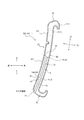
図19〜図20は、第4実施形態に係るシートパッド302を構成するのに好適な多孔質構造体1を説明するための図面である。図19は、本発明の第4実施形態に係るシートパッド302を構成する多孔質構造体1の一部を示す、平面図であり、図7に対応する図面である。図20は、本例の骨部2Bを、単独で示している。図20(a)は骨部2Bに外力が加わっていない自然状態を示しており、図20(b)は骨部2Bに外力が加わった状態を示している。図19及び図20には、骨部2Bの中心軸線(骨格線O)を示している。
図19及び図20(a)に示すように、骨格部2の各骨部2Bは、それぞれ、断面積を一定に保ちつつ延在する、骨一定部2B1と、骨一定部2B1の延在方向の両側において、断面積を徐々に変化させつつ、骨一定部2B1から結合部2Jまで延在する、一対の骨変化部2B2と、から構成されている。本例において、各骨変化部2B2は、断面積を徐々に増大させつつ、骨一定部2B1から結合部2Jまで延在している。なお、本例に限らず、骨格部2を構成する各骨部2Bのうち一部の骨部2Bのみが、この構成を満たしていても、同様の効果が得られる。また、骨格部2を構成する各骨部2Bのうち一部又は全部の骨部2Bは、それぞれ、骨一定部2B1の一方側の端部のみに骨変化部2B2を有し、骨一定部2B1の他方側の端部が直接結合部2Jに結合されていてもよく、その場合も、程度の差はあり得るものの、同様の効果が得られる。
ここで、骨一定部2B1及び骨変化部2B2の断面積は、それぞれ、骨一定部2B1及び骨変化部2B2の骨格線Oに垂直な断面の断面積を指す。
本例では、多孔質構造体1を構成する各骨部2Bが、骨一定部2B1と骨変化部2B2とからなり、骨変化部2B2が、骨一定部2B1から結合部2Jに向かうにつれて断面積が徐々に増大するので、骨部2Bが、骨一定部2B1と骨変化部2B2との境界の近傍部分で、骨一定部2B1に向かって細くなるようにくびれた形状をなしている。そのため、外力が加わる際に、骨部2Bが、そのくびれた部分や骨一定部2B1の中間部分で座屈変形しやすくなり、ひいては、多孔質構造体1が圧縮変形しやすくなる。これにより、化学反応によって発泡させる工程を経て製造された一般的なポリウレタンフォームと同等の挙動及び特性が得られる。また、これにより、多孔質構造体1の表面のタッチ感がより柔らかくなる。よって、例えば、着座する際の、特に着座し始めのタイミングで、着座者に、より柔らかい感触を与えるようになる。このような柔らかい感触は、一般的に、広く好まれるものであり、また、高級車のシートパッドの着座者(例えば運転手付きで後部座席に人を乗せる場合、後部座席に座る着座者)に好まれるものである。
19 to 20 are drawings for explaining a porous structure 1 suitable for forming the seat pad 302 according to the fourth embodiment. FIG. 19 is a plan view showing a part of the porous structure 1 constituting the seat pad 302 according to the fourth embodiment of the present invention, and is a drawing corresponding to FIG. 7. FIG. 20 shows the bone portion 2B of this example alone. FIG. 20 (a) shows a natural state in which no external force is applied to the bone portion 2B, and FIG. 20 (b) shows a state in which an external force is applied to the bone portion 2B. 19 and 20 show the central axis (skeleton line O) of the bone portion 2B.
As shown in FIGS. 19 and 20A, each bone portion 2B of the skeleton portion 2 extends while maintaining a constant cross-sectional area, respectively, in the extending direction of the bone constant portion 2B1 and the bone constant portion 2B1. It is composed of a pair of bone changing portions 2B2 extending from the bone constant portion 2B1 to the connecting portion 2J while gradually changing the cross-sectional area on both sides of the bone. In this example, each bone change portion 2B2 extends from the bone constant portion 2B1 to the joint portion 2J while gradually increasing the cross-sectional area. Not limited to this example, the same effect can be obtained even if only a part of the bone portions 2B constituting the skeleton portion 2 satisfies this configuration. In addition, some or all of the bone portions 2B constituting the skeleton portion 2 have the bone change portion 2B2 only at one end of the bone constant portion 2B1, and the bone constant portion 2B1 The other end may be directly coupled to the coupling portion 2J, and in that case, the same effect can be obtained, although the degree may vary.
Here, the cross-sectional areas of the bone constant portion 2B1 and the bone change portion 2B2 refer to the cross-sectional areas of the cross sections of the bone constant portion 2B1 and the bone change portion 2B2 perpendicular to the skeleton line O, respectively.
In this example, each bone portion 2B constituting the porous structure 1 is composed of a bone constant portion 2B1 and a bone change portion 2B2, and the cross-sectional area of the bone change portion 2B2 increases from the bone constant portion 2B1 to the joint portion 2J. Is gradually increased, so that the bone portion 2B has a constricted shape in the vicinity of the boundary between the bone constant portion 2B1 and the bone change portion 2B2 so as to become thinner toward the bone constant portion 2B1. Therefore, when an external force is applied, the bone portion 2B is likely to be buckled and deformed at the constricted portion and the intermediate portion of the bone constant portion 2B1, and the porous structure 1 is likely to be compressively deformed. As a result, the same behavior and characteristics as general polyurethane foam produced through the step of foaming by a chemical reaction can be obtained. Further, as a result, the touch feeling on the surface of the porous structure 1 becomes softer. Therefore, for example, when sitting, especially at the timing of starting to sit, the seated person is given a softer feel. Such a soft feel is generally preferred by those seated in luxury car seat pads (eg, seated in the backseat when carrying a person in the backseat with a driver). Is what is done.

本例のように、骨部2Bが、その少なくとも一部分において骨一定部2B1を有している場合、骨部2Bのいずれか一方側(好ましくは両側)の端2B21の断面積A1(図20(a))に対する、骨一定部2B1の断面積A0(図20(a))の比A0/A1は、
0.15≦A0/A1≦2.0
を満たしていると、好適である。これにより、多孔質構造体1の表面のタッチ感を、シートパッドの特性として、柔らかすぎず、硬すぎず、ほどよい硬さにすることができる。よって、例えば、着座する際の、特に着座し始めのタイミングで、着座者に、ほどよい硬さの感触を与えるようになる。比A0/A1が小さいほど、多孔質構造体1の表面のタッチ感が、より柔らかくなる。比A0/A1が0.15未満である場合は、多孔質構造体1の表面のタッチ感が柔らかくなりすぎて、シートパッドの特性として好ましくなくなるおそれがあり、また、3Dプリンタによる製造がしにくくなるため、製造性の面で好ましくない。比A0/A1が2.0超である場合は、多孔質構造体1の表面のタッチ感が硬くなりすぎて、シートパッドの特性として好ましくなくなるおそれがある。
なお、比A0/A1は、0.5以上であると、より好適である。
より具体的に、本例では、骨部2Bが骨一定部2B1とその両側に連続する一対の骨変化部2B2とを有しており、各骨変化部2B2が、それぞれ、断面積を徐々に増大させつつ、骨一定部2B1から結合部2Jまで延在しており、比A0/A1が1.0未満である。これにより、多孔質構造体1の表面のタッチ感を、シートパッドの特性として、比較的柔らかくすることができる。このような柔らかい感触は、一般的に、広く好まれるものであり、また、高級車のシートパッドの着座者(例えば運転手付きで後部座席に人を乗せる場合、後部座席に座る着座者)に好まれるものである。
なお、骨格部2を構成する各骨部2Bがこの構成を満たしていてもよいし、あるいは、骨格部2を構成する各骨部2Bのうち一部の骨部2Bのみが、この構成を満たしていてもよく、いずれの場合でも、程度の差はあり得るものの、同様の効果が得られる。
As in this example, when the bone portion 2B has the bone constant portion 2B1 in at least a part thereof, the cross-sectional area A1 of the end 2B21 on either one side (preferably both sides) of the bone portion 2B (FIG. 20 (FIG. 20). The ratio A0 / A1 of the cross-sectional area A0 (FIG. 20 (a)) of the fixed bone portion 2B1 to a)) is
0.15 ≤ A0 / A1 ≤ 2.0
It is preferable that the above conditions are satisfied. As a result, the touch feeling on the surface of the porous structure 1 can be made not too soft, not too hard, and moderately hard as a characteristic of the seat pad. Therefore, for example, when sitting, especially at the timing of starting to sit, the seated person is given a feeling of moderate hardness. The smaller the ratio A0 / A1, the softer the touch feeling on the surface of the porous structure 1. If the ratio A0 / A1 is less than 0.15, the touch feeling on the surface of the porous structure 1 may become too soft, which may be unfavorable as a characteristic of the seat pad, and it is difficult to manufacture with a 3D printer. Therefore, it is not preferable in terms of manufacturability. When the ratio A0 / A1 is more than 2.0, the touch feeling on the surface of the porous structure 1 becomes too hard, which may be unfavorable as a characteristic of the seat pad.
The ratio A0 / A1 is more preferably 0.5 or more.
More specifically, in this example, the bone portion 2B has a bone constant portion 2B1 and a pair of bone change portions 2B2 continuous on both sides thereof, and each bone change portion 2B2 gradually increases its cross-sectional area. While increasing, it extends from the fixed bone portion 2B1 to the connecting portion 2J, and the ratio A0 / A1 is less than 1.0. As a result, the touch feeling on the surface of the porous structure 1 can be made relatively soft as a characteristic of the seat pad. Such a soft feel is generally preferred by those seated in luxury car seat pads (eg, seated in the backseat when carrying a person in the backseat with a driver). Is what is done.
It should be noted that each bone portion 2B constituting the skeleton portion 2 may satisfy this configuration, or only a part of the bone portions 2B among the bone portions 2B constituting the skeleton portion 2 satisfies this configuration. In either case, the same effect can be obtained, although the degree may vary.

なお、本例に代えて、骨変化部2B2は、断面積を徐々に減少させつつ、骨一定部2B1から結合部2Jまで延在していてもよい。この場合、骨一定部2B1は、骨変化部2B2よりも、断面積が大きく(太く)なる。これにより、外力が加わる際に、骨一定部2B1が変形しにくくなり、代わりに、比較的座屈しやすい箇所が骨変化部2B2(特に、連結部2J側の部分)となり、ひいては、多孔質構造体1が圧縮変形しにくくなる。これにより、多孔質構造体1の表面のタッチ感がより硬くなり、また、高硬度の機械特性が得られる。よって、例えば、着座する際の、特に着座し始めのタイミングで、着座者に、より硬い感触を与えるようになる。このような挙動は、化学反応によって発泡させる工程を経て製造された一般的なポリウレタンフォームでは得ることができない。このような構成により、硬めの感触を好むユーザに対応できる。このような硬い感触は、例えば、素早い加減速や斜線変更を行うようなスポーツ車のシートパッドにおける、着座者に好まれるものである。
そして、骨変化部2B2が、断面積を徐々に減少させつつ、骨一定部2B1から結合部2Jまで延在している場合、比A0/A1は、1.0超となる。
なお、骨格部2を構成する各骨部2Bがこの構成を満たしていてもよいし、あるいは、骨格部2を構成する各骨部2Bのうち一部の骨部2Bのみが、この構成を満たしていてもよく、いずれの場合でも、程度の差はあり得るものの、同様の効果が得られる。
Instead of this example, the bone change portion 2B2 may extend from the bone constant portion 2B1 to the joint portion 2J while gradually reducing the cross-sectional area. In this case, the bone constant portion 2B1 has a larger (thicker) cross-sectional area than the bone change portion 2B2. As a result, when an external force is applied, the fixed bone portion 2B1 is less likely to be deformed, and instead, the portion that is relatively easy to buckle becomes the bone changing portion 2B2 (particularly, the portion on the connecting portion 2J side), and thus the porous structure. The body 1 is less likely to be compressed and deformed. As a result, the touch feeling on the surface of the porous structure 1 becomes harder, and mechanical properties of high hardness can be obtained. Therefore, for example, when sitting, especially at the timing of starting to sit, the seated person is given a harder feel. Such behavior cannot be obtained with a general polyurethane foam produced through a step of foaming by a chemical reaction. Such a configuration can accommodate users who prefer a stiffer feel. Such a hard feel is preferred by the seated person, for example, in the seat pad of a sports car that performs quick acceleration / deceleration and change of diagonal line.
Then, when the bone changing portion 2B2 extends from the bone constant portion 2B1 to the connecting portion 2J while gradually reducing the cross-sectional area, the ratio A0 / A1 becomes more than 1.0.
It should be noted that each bone portion 2B constituting the skeleton portion 2 may satisfy this configuration, or only a part of the bone portions 2B among the bone portions 2B constituting the skeleton portion 2 satisfies this configuration. In either case, the same effect can be obtained, although the degree may vary.

なお、第1実施形態において上述した図6〜図9の例において、骨部2Bは、骨変化部2B2を有さずに、骨一定部2B1のみからなるものである。この場合、骨部2の断面積は、その全長にわたって一定になる。そして、外力が加わる際における多孔質構造体1の表面のタッチ感は、中程度の硬さになる。このような構成により、中程度の硬さの感触を好むユーザに対応できる。また、高級車やスポーツ車など、あらゆる車種のシートパッドに好適に適用できる。
この場合、比A0/A1は、1.0となる。
なお、骨格部2を構成する各骨部2Bがこの構成を満たしていてもよいし、あるいは、骨格部2を構成する各骨部2Bのうち一部の骨部2Bのみが、この構成を満たしていてもよく、いずれの場合でも、程度の差はあり得るものの、同様の効果が得られる。
In the example of FIGS. 6 to 9 described above in the first embodiment, the bone portion 2B does not have the bone change portion 2B2 and is composed of only the bone constant portion 2B1. In this case, the cross-sectional area of the bone portion 2 is constant over its entire length. Then, the touch feeling on the surface of the porous structure 1 when an external force is applied becomes moderate hardness. Such a configuration can accommodate users who prefer a medium hardness feel. In addition, it can be suitably applied to seat pads of all types of vehicles such as luxury cars and sports cars.
In this case, the ratio A0 / A1 is 1.0.
It should be noted that each bone portion 2B constituting the skeleton portion 2 may satisfy this configuration, or only a part of the bone portions 2B among the bone portions 2B constituting the skeleton portion 2 satisfies this configuration. In either case, the same effect can be obtained, although the degree may vary.

図19〜図20の例に戻り、本例において、骨格部2を構成する各骨部2Bは、骨一定部2B1が、骨変化部2B2及び結合部2Jよりも、断面積が小さい。より具体的には、骨一定部2B1の断面積は、骨変化部2B2及び結合部2Jのそれぞれのどの部分(ただし、骨一定部2B1と骨変化部2B2との境界部分を除く)の断面積よりも、小さい。すなわち、骨一定部2B1は、骨格部2の中で最も断面積が小さい(細い)部分である。これにより、上述したことと同様に、外力が加わる際に、骨一定部2B1が変形しやすくなり、ひいては、多孔質構造体1が圧縮変形しやすくなる。これにより、多孔質構造体1の表面のタッチ感がより柔らかくなる。
なお、結合部2Jの断面積は、結合部2Jの骨格線Oに垂直な断面の断面積を指す。
なお、本例に限らず、骨格部2を構成する各骨部2Bのうち一部の骨部2Bのみが、この構成を満たしていてもよく、その場合でも、程度の差はあり得るものの、同様の効果が得られる。
Returning to the examples of FIGS. 19 to 20, in this example, the bone constant portion 2B1 of each bone portion 2B constituting the skeleton portion 2 has a smaller cross-sectional area than the bone change portion 2B2 and the joint portion 2J. More specifically, the cross-sectional area of the fixed bone portion 2B1 is the cross-sectional area of each of the bone changing portion 2B2 and the connecting portion 2J (however, excluding the boundary portion between the bone constant portion 2B1 and the bone changing portion 2B2). Smaller than. That is, the fixed bone portion 2B1 is a portion having the smallest (thin) cross-sectional area in the skeleton portion 2. As a result, similarly to the above, when an external force is applied, the bone constant portion 2B1 is easily deformed, and by extension, the porous structure 1 is easily deformed by compression. As a result, the touch feeling on the surface of the porous structure 1 becomes softer.
The cross-sectional area of the connecting portion 2J refers to the cross-sectional area of the cross section perpendicular to the skeleton line O of the connecting portion 2J.
Not limited to this example, only a part of the bones 2B constituting the skeleton 2 may satisfy this configuration, and even in that case, the degree may vary. A similar effect can be obtained.

同様に、本例において、骨格部2を構成する各骨部2Bは、骨一定部2B1が、骨変化部2B2及び結合部2Jよりも、幅が小さい。より具体的には、骨一定部2B1の幅は、骨変化部2B2及び結合部2Jのそれぞれのどの部分(ただし、骨一定部2B1と骨変化部2B2との境界部分を除く)の幅よりも、小さい。すなわち、骨一定部2B1は、骨格部2の中で最も幅が小さい(細い)部分である。これによっても、外力が加わる際に骨一定部2B1が変形しやすくなり、それにより、多孔質構造体1の表面のタッチ感がより柔らかくなる。
なお、骨一定部2B1、骨変化部2B2、結合部2Jの幅は、それぞれ、骨一定部2B1、骨変化部2B2、結合部2Jの骨格線Oに垂直な断面に沿って測ったときの、当該断面における最大幅を指す。結合部2Jの骨格線Oは、骨格線Oのうち、結合部2Jに対応する部分である。図20(a)には、参考のため、骨一定部2B1の幅W0と、骨変化部2B2の幅W1とを、示している。
なお、本例に限らず、骨格部2を構成する各骨部2Bのうち一部の骨部2Bのみが、この構成を満たしていてもよく、その場合でも、程度の差はあり得るものの、同様の効果が得られる。
Similarly, in this example, in each bone portion 2B constituting the skeleton portion 2, the bone constant portion 2B1 is smaller in width than the bone change portion 2B2 and the joint portion 2J. More specifically, the width of the bone constant portion 2B1 is larger than the width of each of the bone change portion 2B2 and the joint portion 2J (excluding the boundary portion between the bone constant portion 2B1 and the bone change portion 2B2). ,small. That is, the fixed bone portion 2B1 is the narrowest (thin) portion in the skeleton portion 2. This also makes it easier for the bone constant portion 2B1 to be deformed when an external force is applied, whereby the touch feeling on the surface of the porous structure 1 becomes softer.
The widths of the bone constant portion 2B1, the bone change portion 2B2, and the joint portion 2J were measured along the cross section perpendicular to the skeleton line O of the bone constant portion 2B1, the bone change portion 2B2, and the joint portion 2J, respectively. Refers to the maximum width in the cross section. The skeleton line O of the connecting portion 2J is a portion of the skeleton line O corresponding to the connecting portion 2J. FIG. 20A shows the width W0 of the bone constant portion 2B1 and the width W1 of the bone change portion 2B2 for reference.
Not limited to this example, only a part of the bones 2B constituting the skeleton 2 may satisfy this configuration, and even in that case, the degree may vary. A similar effect can be obtained.

上述した各例において、多孔質構造体1の構造の簡単化、ひいては、3Dプリンタの製造のし易さの観点からは、骨一定部2B1の幅W0(図20)は、0.05mm以上であると好適であり、0.10mm以上であるとより好適である。幅W0が0.05mm以上の場合、高性能な3Dプリンタの解像度で造形可能であり、0.10mm以上の場合、高性能な3Dプリンタだけでなく汎用の3Dプリンタの解像度でも造形可能である。
一方、多孔質構造体1の外縁(外輪郭)形状の精度を向上させる観点や、セル孔C間の隙間(間隔)を小さくする観点や、クッション材としての特性を良好にする観点からは、骨一定部2B1の幅W0(図20)は、0.05mm以上2.0mm以下であると好適である。
なお、骨格部2を構成する各骨部2Bがこの構成を満たしていると好適であるが、骨格部2を構成する各骨部2Bのうち一部の骨部2Bのみが、この構成を満たしていてもよく、その場合でも、程度の差はあり得るものの、同様の効果が得られる。
In each of the above examples, the width W0 (FIG. 20) of the bone constant portion 2B1 is 0.05 mm or more from the viewpoint of simplification of the structure of the porous structure 1 and thus the ease of manufacturing a 3D printer. It is preferable to have it, and it is more preferable to have it of 0.10 mm or more. When the width W0 is 0.05 mm or more, modeling is possible with the resolution of a high-performance 3D printer, and when the width W0 is 0.10 mm or more, modeling is possible not only with the resolution of a high-performance 3D printer but also with the resolution of a general-purpose 3D printer.
On the other hand, from the viewpoint of improving the accuracy of the outer edge (outer contour) shape of the porous structure 1, reducing the gap (interval) between the cell holes C, and improving the characteristics as a cushioning material, The width W0 (FIG. 20) of the fixed bone portion 2B1 is preferably 0.05 mm or more and 2.0 mm or less.
It is preferable that each bone portion 2B constituting the skeleton portion 2 satisfies this configuration, but only a part of the bone portions 2B constituting the skeleton portion 2 satisfies this configuration. In that case, the same effect can be obtained, although the degree may vary.

図20に示すように、本例において、骨格部2を構成する各骨部2Bは、骨変化部2B2が、その側面に、1又は複数(本例では、3つ)の傾斜面2B23を有しており、この傾斜面2B23は、骨変化部2B2の延在方向に対して傾斜(90°未満で傾斜)しているとともに、骨一定部2B1から結合部2Jに向かうにつれて、幅W2が徐々に増大している。
これによっても、外力が加わる際に、骨部2Bが、骨一定部2B1と骨変化部2B2との境界近傍におけるくびれた部分で、座屈変形しやすくなり、ひいては、多孔質構造体1が圧縮変形しやすくなる。これにより、多孔質構造体1の表面のタッチ感がより柔らかくなる。
ここで、骨変化部2B2の延在方向は、骨変化部2B2の中心軸線(骨格線O)の延在方向である。また、骨変化部2B2の傾斜面2B23の幅W2は、骨変化部2B2の骨格線Oに垂直な断面に沿って測ったときの、傾斜面2B23の幅を指す。
なお、本例に限らず、骨格部2を構成する各骨部2Bのうち一部の骨部2Bのみが、この構成を満たしていてもよく、その場合でも、程度の差はあり得るものの、同様の効果が得られる。
As shown in FIG. 20, in this example, each bone portion 2B constituting the skeleton portion 2 has one or a plurality (three in this example) inclined surfaces 2B23 on the side surface of each bone changing portion 2B2. The inclined surface 2B23 is inclined (inclined at less than 90 °) with respect to the extending direction of the bone changing portion 2B2, and the width W2 gradually increases from the bone constant portion 2B1 toward the connecting portion 2J. Is increasing.
As a result, when an external force is applied, the bone portion 2B is easily buckled and deformed at the constricted portion near the boundary between the bone constant portion 2B1 and the bone change portion 2B2, and as a result, the porous structure 1 is compressed. It becomes easy to deform. As a result, the touch feeling on the surface of the porous structure 1 becomes softer.
Here, the extending direction of the bone changing portion 2B2 is the extending direction of the central axis (skeleton line O) of the bone changing portion 2B2. Further, the width W2 of the inclined surface 2B23 of the bone changing portion 2B2 refers to the width of the inclined surface 2B23 when measured along the cross section perpendicular to the skeleton line O of the bone changing portion 2B2.
Not limited to this example, only a part of the bones 2B constituting the skeleton 2 may satisfy this configuration, and even in that case, the degree may vary. A similar effect can be obtained.

本例において、骨格部2を構成する各骨部2Bにおいて、それぞれ柱状であるとともに、骨一定部2B1と骨変化部2B2は、それぞれの断面形状が、正三角形である。
これにより、多孔質構造体1の構造がシンプルになり、3Dプリンタによる造形がしやすくなる。また、化学反応によって発泡させる工程を経て製造された一般的なポリウレタンフォームでの機械特性を再現しやすい。よって、多孔質構造体1のクッション材としての特性を向上できる。また、このように骨部2Bを柱状に構成することにより、仮に骨部2Bを薄い膜状の部分に置き換えた場合に比べて、多孔質構造体1の耐久性を向上できる。
なお、骨一定部2B1、骨変化部2B2の断面形状は、それぞれ、骨一定部2B1、骨変化部2B2の中心軸線(骨格線O)に垂直な断面における形状である。
なお、本例に限らず、骨格部2を構成する各骨部2Bのうち一部の骨部2Bのみが、この構成を満たしていてもよく、その場合でも、程度の差はあり得るものの、同様の効果が得られる。
また、骨格部2を構成する各骨部2Bのうち全部又は一部の骨部2Bにおいて、骨一定部2B1と骨変化部2B2は、それぞれの断面形状が、正三角形以外の多角形(正三角形以外の三角形、四角形等)でもよいし、あるいは、円形(真円形、楕円形等)でもよく、その場合でも、本例と同様の効果が得られる。また、骨一定部2B1と骨変化部2B2は、それぞれの断面形状が互いに異なるものでもよい。また、各骨部2Bは、それぞれの断面形状が、その延在方向に沿って均一でもよいし、あるいは、その延在方向に沿って非均一でもよい。また、各骨部2Bどうしで、断面形状が互いに異なっていてもよい。
In this example, each bone portion 2B constituting the skeleton portion 2 has a columnar shape, and the bone constant portion 2B1 and the bone change portion 2B2 have equilateral triangular cross-sectional shapes.
This simplifies the structure of the porous structure 1 and facilitates modeling with a 3D printer. In addition, it is easy to reproduce the mechanical properties of a general polyurethane foam produced through a process of foaming by a chemical reaction. Therefore, the characteristics of the porous structure 1 as a cushioning material can be improved. Further, by forming the bone portion 2B in a columnar shape in this way, the durability of the porous structure 1 can be improved as compared with the case where the bone portion 2B is replaced with a thin film-like portion.
The cross-sectional shapes of the bone constant portion 2B1 and the bone change portion 2B2 are shapes in a cross section perpendicular to the central axis (skeleton line O) of the bone constant portion 2B1 and the bone change portion 2B2, respectively.
Not limited to this example, only a part of the bones 2B constituting the skeleton 2 may satisfy this configuration, and even in that case, the degree may vary. A similar effect can be obtained.
Further, in all or part of the bone portions 2B constituting the skeleton portion 2, the bone constant portion 2B1 and the bone change portion 2B2 have polygonal shapes other than the equilateral triangle (equilateral triangle). Other than triangles, quadrangles, etc.), or circular (round, oval, etc.) may be used, and even in that case, the same effect as in this example can be obtained. Further, the bone constant portion 2B1 and the bone change portion 2B2 may have different cross-sectional shapes. Further, each bone portion 2B may have a uniform cross-sectional shape along the extending direction thereof, or may be non-uniform along the extending direction thereof. Further, the cross-sectional shapes of the bone portions 2B may be different from each other.

なお、上述した第4実施形態における骨格部2の骨部2Bの構成は、第1実施形態、第2実施形態、及び第3実施形態のいずれの骨格部2の骨部2Bに適用してもよい。 The configuration of the bone portion 2B of the skeleton portion 2 in the above-described fourth embodiment may be applied to the bone portion 2B of the skeleton portion 2 of any of the first embodiment, the second embodiment, and the third embodiment. Good.

本発明のシートパッドの製造方法、シートパッド、及び、3D造形用データは、任意の乗り物用シート及び任意の乗り物用シートパッドに用いられると好適であり、特に、車両用シート及び車両用シートパッドに用いられると好適なものである。 The seat pad manufacturing method, seat pad, and 3D modeling data of the present invention are preferably used for any vehicle seat and any vehicle seat pad, and in particular, a vehicle seat and a vehicle seat pad. It is suitable to be used in.

300:車両用シート、
302:シートパッド、
310:クッションパッド、 311:メインパッド部(着座部)、 311t:腿下部、 311h:尻下部、 312:サイドパッド部、 313:バックパッド対向部、
320:バックパッド、 321:メインパッド部、 322:サイドパッド部、
330:表皮、
340:ヘッドレスト、
5:流体通路、 51:第1開口(開口)、 52:第2開口(開口)、 53:本通路、 54a〜54e:分岐通路、 55:中間通路、 56:分岐部、
P、P1、P2:分岐点、
FS:着座者側の面(表面)、 SS:側面、 BS:裏面、 Ga〜Gb:溝、
TD:厚さ方向、 LD:延在方向、
1:多孔質構造体、
2:骨格部、 2B:骨部、 2Be:骨部の端部、 2B1:骨一定部、 2B2:骨変化部、 2B21:骨変化部の結合部側の端、 2B22:骨変化部の骨一定部側の端、 2B23:骨変化部の傾斜面、 2J:結合部、 21:セル区画部、 211:環状部、 211L:大環状部、 211S:小環状部、 2111:環状部の内周側縁部、
3:膜、
6:表皮部、 6B:貫通孔、 6C:柱部、 6Ce:柱部の端部、
7A:流体通路近傍部分、 7B:流体通路近傍部分以外の部分
C:セル孔、 O:骨格線、 V1:仮想面、 V1L:大仮想面、 V1S:小仮想面
400:3Dプリンタ、 410:制御部、 420:造形部、 421:レーザ照射器、 430:支持台、 440:収容体、 LL:紫外線レーザ光、 LR:液体樹脂、 500:3D造形用データ
300: Vehicle seat,
302: Seat pad,
310: Cushion pad, 311: Main pad part (seating part), 311t: Lower thigh, 311h: Lower buttock, 312: Side pad part, 313: Back pad facing part,
320: Back pad, 321: Main pad, 322: Side pad,
330: Epidermis,
340: Headrest,
5: Fluid passage, 51: First opening (opening), 52: Second opening (opening), 53: Main passage, 54a to 54e: Branch passage, 55: Intermediate passage, 56: Branch part,
P, P1, P2: junction,
FS: Seated side surface (front surface), SS: Side surface, BS: Back surface, Ga to Gb: Groove,
TD: thickness direction, LD: extension direction,
1: Porous structure,
2: Skeleton part, 2B: Bone part, 2Be: Bone part end, 2B1: Bone constant part, 2B2: Bone change part, 2B21: Bone change part joint side end, 2B22: Bone constant part of bone change part End on the part side, 2B23: Inclined surface of bone change part, 2J: Joint part, 21: Cell compartment part, 211: Ring part, 211L: Large ring part, 211S: Small ring part, 2111: Inner circumference side of ring part Edge,
3: Membrane,
6: Epidermis, 6B: Through hole, 6C: Pillar, 6Ce: End of pillar,
7A: Part near the fluid passage, 7B: Part other than the part near the fluid passage C: Cell hole, O: Skeleton line, V1: Virtual surface, V1L: Large virtual surface, V1S: Small virtual surface 400: 3D printer, 410: Control Part, 420: Modeling part, 421: Laser irradiator, 430: Support stand, 440: Container, LL: Ultraviolet laser light, LR: Liquid resin, 500: Data for 3D modeling

Claims (11)

多孔質構造体から構成されたシートパッドの製造方法であって、
3Dプリンタを用いて前記シートパッドを造形する、造形ステップを含み、
前記多孔質構造体は、可撓性のある樹脂又はゴムから構成されており、
前記シートパッドは、前記シートパッドの外表面に開口する第1開口から、前記シートパッドの内部を延在し、前記シートパッドの外表面に開口する第2開口までに至る、流体が通るための流体通路を有しており、
前記流体通路の前記第2開口は、前記シートパッドの着座者側の面に開口している、シートパッドの製造方法。
A method for manufacturing a seat pad composed of a porous structure.
Includes a modeling step of modeling the seat pad using a 3D printer.
The porous structure is made of a flexible resin or rubber.
The seat pad is for fluid to pass from a first opening that opens to the outer surface of the seat pad to a second opening that extends inside the seat pad and opens to the outer surface of the seat pad. Has a fluid passage and
A method for manufacturing a seat pad, wherein the second opening of the fluid passage is open to a seater-side surface of the seat pad.
前記流体通路は、複数の分岐通路を有している、請求項1に記載のシートパッドの製造方法。 The method for manufacturing a seat pad according to claim 1, wherein the fluid passage has a plurality of branch passages. 前記複数の分岐通路は、それぞれ、前記シートパッドの前記着座者側の面に開口する前記第2開口を有している、請求項1又は2に記載のシートパッドの製造方法。 The method for manufacturing a seat pad according to claim 1 or 2, wherein each of the plurality of branch aisles has the second opening that opens to the seater-side surface of the seat pad. 前記シートパッドは、クッションパッドとして構成されており、
前記クッションパッドは、着座者の尻部を下側から支持するように構成された尻下部を有しており、
前記流体通路の前記第2開口は、前記尻下部の着座者側の面に開口している、請求項1〜3のいずれか一項に記載のシートパッドの製造方法。
The seat pad is configured as a cushion pad.
The cushion pad has a lower buttock configured to support the buttock portion of the seated person from below.
The method for manufacturing a seat pad according to any one of claims 1 to 3, wherein the second opening of the fluid passage is open to the seater-side surface of the lower buttock.
前記シートパッドは、バックパッドとして構成されており、
前記バックパッドは、着座者の背中を後側から支持するように構成されたメインパッド部を有しており、
前記流体通路の前記第2開口は、前記メインパッド部の着座者側の面に開口している、請求項1〜3のいずれか一項に記載のシートパッドの製造方法。
The seat pad is configured as a back pad.
The back pad has a main pad portion configured to support the back of the seated person from the rear side.
The method for manufacturing a seat pad according to any one of claims 1 to 3, wherein the second opening of the fluid passage is open to the seater-side surface of the main pad portion.
前記流体通路の前記第1開口は、前記シートパッドの外表面のうち前記着座者側の面以外の面に開口している、請求項1〜5のいずれか一項に記載のシートパッドの製造方法。 The manufacture of a seat pad according to any one of claims 1 to 5, wherein the first opening of the fluid passage is open to a surface other than the seating side surface of the outer surface of the seat pad. Method. 前記多孔質構造体は、骨格部を備えており、
前記骨格部は、
複数の骨部と、
それぞれ前記複数の骨部の端部どうしを結合する、複数の結合部と、
から構成されており、
前記骨格部は、セル孔を内部に区画するセル区画部を有しており、
前記セル区画部は、それぞれ環状に構成された複数の環状部を有しており、
前記複数の環状部は、それぞれの内周側縁部によって区画する仮想面どうしが交差しないように互いに連結されており、
前記セル孔は、前記複数の環状部と、前記複数の環状部がそれぞれ区画する複数の前記仮想面とによって、区画されており、
前記環状部は、複数の前記骨部と複数の前記結合部とから構成されている、請求項1〜6のいずれか一項に記載のシートパッドの製造方法。
The porous structure includes a skeleton portion and has a skeleton portion.
The skeleton is
With multiple bones
A plurality of joints, each of which connects the ends of the plurality of bones,
Consists of
The skeleton portion has a cell partition portion that internally partitions the cell hole.
Each of the cell compartments has a plurality of annular portions configured in an annular shape.
The plurality of annular portions are connected to each other so that the virtual surfaces partitioned by the respective inner peripheral side edges do not intersect with each other.
The cell hole is partitioned by the plurality of annular portions and the plurality of virtual surfaces on which the plurality of annular portions are partitioned.
The method for manufacturing a seat pad according to any one of claims 1 to 6, wherein the annular portion is composed of a plurality of the bone portions and the plurality of joint portions.
多孔質構造体から構成されたシートパッドであって、
前記シートパッドは、3Dプリンタを用いて造形されたものであり、
前記多孔質構造体は、可撓性のある樹脂又はゴムから構成されており、
前記シートパッドは、前記シートパッドの外表面に開口する第1開口から、前記シートパッドの内部を延在し、前記シートパッドの外表面に開口する第2開口までに至る、流体が通るための流体通路を有しており、
前記流体通路の前記第2開口は、前記シートパッドの着座者側の面に開口している、シートパッド。
A seat pad composed of a porous structure.
The seat pad was modeled using a 3D printer.
The porous structure is made of a flexible resin or rubber.
The seat pad is for fluid to pass from a first opening that opens to the outer surface of the seat pad to a second opening that extends inside the seat pad and opens to the outer surface of the seat pad. Has a fluid passage and
The second opening of the fluid passage is a seat pad that opens to the seater-side surface of the seat pad.
前記多孔質構造体は、骨格部を備えており、
前記骨格部は、
複数の骨部と、
それぞれ前記複数の骨部の端部どうしを結合する、複数の結合部と、
から構成されており、
前記骨部は、その断面形状が、円形又は多角形である、請求項8に記載のシートパッド。
The porous structure includes a skeleton portion and has a skeleton portion.
The skeleton is
With multiple bones
A plurality of joints, each of which connects the ends of the plurality of bones,
Consists of
The seat pad according to claim 8, wherein the bone portion has a circular or polygonal cross-sectional shape.
前記多孔質構造体は、骨格部を備えており、
前記骨格部は、
複数の骨部と、
それぞれ前記複数の骨部の端部どうしを結合する、複数の結合部と、
から構成されており、
前記骨部は、その少なくとも一部分において、断面積を一定に保ちつつ延在する骨一定部を有しており、
前記骨部のいずれか一方側の端の断面積A1に対する、前記骨一定部の断面積A0の比A0/A1は、
0.15≦A0/A1≦2.0
を満たす、請求項8又は9に記載のシートパッド。
The porous structure includes a skeleton portion and has a skeleton portion.
The skeleton is
With multiple bones
A plurality of joints, each of which connects the ends of the plurality of bones,
Consists of
The bone portion has, in at least a part thereof, a bone constant portion extending while maintaining a constant cross-sectional area.
The ratio A0 / A1 of the cross-sectional area A0 of the fixed bone portion to the cross-sectional area A1 of one end of the bone portion is
0.15 ≤ A0 / A1 ≤ 2.0
The seat pad according to claim 8 or 9, which satisfies the above conditions.
3Dプリンタの造形部が造形を行う際に前記3Dプリンタの制御部に読み込まれる、3D造形用データであって、
前記制御部が、前記造形部に、請求項8〜10のいずれか一項に記載のシートパッドを、造形させるように構成された、3D造形用データ。
This is 3D modeling data that is read into the control unit of the 3D printer when the modeling unit of the 3D printer performs modeling.
Data for 3D modeling in which the control unit is configured to cause the modeling unit to model the seat pad according to any one of claims 8 to 10.
JP2019076046A 2019-04-12 2019-04-12 Method for manufacturing seat pad, seat pad, and three-dimensional modelling data Pending JP2020172076A (en)

Priority Applications (1)

Application Number Priority Date Filing Date Title
JP2019076046A JP2020172076A (en) 2019-04-12 2019-04-12 Method for manufacturing seat pad, seat pad, and three-dimensional modelling data

Applications Claiming Priority (1)

Application Number Priority Date Filing Date Title
JP2019076046A JP2020172076A (en) 2019-04-12 2019-04-12 Method for manufacturing seat pad, seat pad, and three-dimensional modelling data

Publications (1)

Publication Number Publication Date
JP2020172076A true JP2020172076A (en) 2020-10-22

Family

ID=72829715

Family Applications (1)

Application Number Title Priority Date Filing Date
JP2019076046A Pending JP2020172076A (en) 2019-04-12 2019-04-12 Method for manufacturing seat pad, seat pad, and three-dimensional modelling data

Country Status (1)

Country Link
JP (1) JP2020172076A (en)

Cited By (4)

* Cited by examiner, † Cited by third party
Publication number Priority date Publication date Assignee Title
JP6953045B1 (en) * 2021-03-02 2021-10-27 株式会社シンセイ Metal-organic frameworks and composite members, and methods for manufacturing composite members
WO2022106564A1 (en) 2020-11-19 2022-05-27 Vincador Holding Gmbh Process for producing foam bodies
WO2022264447A1 (en) * 2021-06-15 2022-12-22 株式会社アーケム Seat pad and method for producing seat pad
JP7399076B2 (en) 2020-12-28 2023-12-15 公益財団法人鉄道総合技術研究所 Aerodynamic noise reduction structure of current collector and its manufacturing method

Citations (3)

* Cited by examiner, † Cited by third party
Publication number Priority date Publication date Assignee Title
JP2003285629A (en) * 2002-03-28 2003-10-07 Denso Corp Vehicular seat air conditioner
JP2009029064A (en) * 2007-07-30 2009-02-12 Incs Inc Powdery molded article
WO2018050558A1 (en) * 2016-09-13 2018-03-22 Covestro Deutschland Ag Porous body, additive manufacturing method for the body and apparatus for supporting and/or bearing a person

Patent Citations (4)

* Cited by examiner, † Cited by third party
Publication number Priority date Publication date Assignee Title
JP2003285629A (en) * 2002-03-28 2003-10-07 Denso Corp Vehicular seat air conditioner
JP2009029064A (en) * 2007-07-30 2009-02-12 Incs Inc Powdery molded article
WO2018050558A1 (en) * 2016-09-13 2018-03-22 Covestro Deutschland Ag Porous body, additive manufacturing method for the body and apparatus for supporting and/or bearing a person
JP2019534064A (en) * 2016-09-13 2019-11-28 コベストロ、ドイチュラント、アクチエンゲゼルシャフトCovestro Deutschland Ag Porous body, method for adding porous body, and apparatus for supporting and / or supporting a person

Cited By (6)

* Cited by examiner, † Cited by third party
Publication number Priority date Publication date Assignee Title
WO2022106564A1 (en) 2020-11-19 2022-05-27 Vincador Holding Gmbh Process for producing foam bodies
DE102020130583A1 (en) 2020-11-19 2022-06-09 Vincador Holding Gmbh Process for the production of foam bodies
JP7399076B2 (en) 2020-12-28 2023-12-15 公益財団法人鉄道総合技術研究所 Aerodynamic noise reduction structure of current collector and its manufacturing method
JP6953045B1 (en) * 2021-03-02 2021-10-27 株式会社シンセイ Metal-organic frameworks and composite members, and methods for manufacturing composite members
JP2022133716A (en) * 2021-03-02 2022-09-14 株式会社シンセイ Metal structure, composite member, and method for manufacturing composite member
WO2022264447A1 (en) * 2021-06-15 2022-12-22 株式会社アーケム Seat pad and method for producing seat pad

Similar Documents

Publication Publication Date Title
JP2020172076A (en) Method for manufacturing seat pad, seat pad, and three-dimensional modelling data
JP7335897B2 (en) POROUS STRUCTURE, POROUS STRUCTURE MANUFACTURING METHOD, AND CUSHION MATERIAL FOR SEAT
WO2020208939A1 (en) Method for manufacturing seat sheet cushion material, cushion material for seat sheet, method for manufacturing filler, and filler
JP2020090080A (en) Porous structure, manufacturing method of porous structure, data for 3d molding, and cushion material for seat
WO2020208938A1 (en) Porous structure and vehicular headrest
JP7427606B2 (en) Cushion material, manufacturing method of cushion material, and seat sheet
JP7389024B2 (en) Porous structure, porous structure manufacturing method, and 3D printing data
JP7389026B2 (en) Porous structure, porous structure manufacturing method, and 3D printing data
JP7389025B2 (en) Porous structure, porous structure manufacturing method, and 3D printing data
JP7225226B2 (en) Porous structure, method for manufacturing porous structure, and data for 3D printing
WO2020235154A1 (en) Porous structure and porous structure manufacturing method
WO2022064760A1 (en) Porous structure and method for producing porous structure
JP7444783B2 (en) Method for manufacturing a loading body, method for manufacturing a cushion material for a seat, and a loading body
JP6691951B2 (en) Porous structure, method for producing porous structure, and 3D modeling data
WO2020116327A1 (en) Method for producing porous structure, porous structure and seat pad
JP6644183B1 (en) Porous structure, method for manufacturing porous structure, and 3D modeling data
JP7258652B2 (en) Porous structure, method for manufacturing porous structure, and data for 3D printing
JP2022012973A (en) Porous structure and manufacturing method of porous structure
JP7469018B2 (en) Cushioning material, cushioning device, and method for manufacturing cushioning material
JP2022049528A (en) Porous structure and manufacturing method of the same
JP2022049527A (en) Cushion body and manufacturing method of the same
WO2022264447A1 (en) Seat pad and method for producing seat pad
JP2022017082A (en) Cushion body and manufacturing method of the same

Legal Events

Date Code Title Description
A621 Written request for application examination

Free format text: JAPANESE INTERMEDIATE CODE: A621

Effective date: 20211217

A711 Notification of change in applicant

Free format text: JAPANESE INTERMEDIATE CODE: A712

Effective date: 20220831

A977 Report on retrieval

Free format text: JAPANESE INTERMEDIATE CODE: A971007

Effective date: 20221007

A131 Notification of reasons for refusal

Free format text: JAPANESE INTERMEDIATE CODE: A131

Effective date: 20221018

A02 Decision of refusal

Free format text: JAPANESE INTERMEDIATE CODE: A02

Effective date: 20230411