JP7391893B2 - Golf club head including flexible sole - Google Patents
Golf club head including flexible sole Download PDFInfo
- Publication number
- JP7391893B2 JP7391893B2 JP2020572531A JP2020572531A JP7391893B2 JP 7391893 B2 JP7391893 B2 JP 7391893B2 JP 2020572531 A JP2020572531 A JP 2020572531A JP 2020572531 A JP2020572531 A JP 2020572531A JP 7391893 B2 JP7391893 B2 JP 7391893B2
- Authority
- JP
- Japan
- Prior art keywords
- club head
- sole
- golf club
- depth
- inches
- Prior art date
- Legal status (The legal status is an assumption and is not a legal conclusion. Google has not performed a legal analysis and makes no representation as to the accuracy of the status listed.)
- Active
Links
- 230000007704 transition Effects 0.000 claims description 33
- 230000007423 decrease Effects 0.000 claims description 2
- 239000000463 material Substances 0.000 description 20
- 239000010936 titanium Substances 0.000 description 17
- 230000001965 increasing effect Effects 0.000 description 14
- 239000002184 metal Substances 0.000 description 13
- 229910052751 metal Inorganic materials 0.000 description 13
- 238000000034 method Methods 0.000 description 13
- 229910000831 Steel Inorganic materials 0.000 description 12
- 239000010959 steel Substances 0.000 description 12
- 239000002023 wood Substances 0.000 description 10
- 230000008901 benefit Effects 0.000 description 8
- 238000004519 manufacturing process Methods 0.000 description 5
- 229910000851 Alloy steel Inorganic materials 0.000 description 4
- 229910001092 metal group alloy Inorganic materials 0.000 description 4
- 239000002131 composite material Substances 0.000 description 3
- 230000008520 organization Effects 0.000 description 3
- 230000009467 reduction Effects 0.000 description 3
- 229910000838 Al alloy Inorganic materials 0.000 description 2
- 229910001240 Maraging steel Inorganic materials 0.000 description 2
- 229910001069 Ti alloy Inorganic materials 0.000 description 2
- 229910000883 Ti6Al4V Inorganic materials 0.000 description 2
- 238000010168 coupling process Methods 0.000 description 2
- -1 etc.) ) Inorganic materials 0.000 description 2
- 239000004033 plastic Substances 0.000 description 2
- 239000010935 stainless steel Substances 0.000 description 2
- 229910001220 stainless steel Inorganic materials 0.000 description 2
- RTAQQCXQSZGOHL-UHFFFAOYSA-N Titanium Chemical compound [Ti] RTAQQCXQSZGOHL-UHFFFAOYSA-N 0.000 description 1
- 230000008859 change Effects 0.000 description 1
- 238000010276 construction Methods 0.000 description 1
- 230000003247 decreasing effect Effects 0.000 description 1
- 230000002708 enhancing effect Effects 0.000 description 1
- 230000014509 gene expression Effects 0.000 description 1
- 230000005484 gravity Effects 0.000 description 1
- 238000007373 indentation Methods 0.000 description 1
- 238000012986 modification Methods 0.000 description 1
- 230000004048 modification Effects 0.000 description 1
- 230000002787 reinforcement Effects 0.000 description 1
- 230000003014 reinforcing effect Effects 0.000 description 1
- 230000008439 repair process Effects 0.000 description 1
- 239000011347 resin Substances 0.000 description 1
- 229920005989 resin Polymers 0.000 description 1
- 239000003351 stiffener Substances 0.000 description 1
- 238000006467 substitution reaction Methods 0.000 description 1
- 229920001169 thermoplastic Polymers 0.000 description 1
- 239000004416 thermosoftening plastic Substances 0.000 description 1
- 229910052719 titanium Inorganic materials 0.000 description 1
- 238000003466 welding Methods 0.000 description 1
Images


Classifications
-
- A—HUMAN NECESSITIES
- A63—SPORTS; GAMES; AMUSEMENTS
- A63B—APPARATUS FOR PHYSICAL TRAINING, GYMNASTICS, SWIMMING, CLIMBING, OR FENCING; BALL GAMES; TRAINING EQUIPMENT
- A63B53/00—Golf clubs
- A63B53/04—Heads
- A63B53/0466—Heads wood-type
-
- A—HUMAN NECESSITIES
- A63—SPORTS; GAMES; AMUSEMENTS
- A63B—APPARATUS FOR PHYSICAL TRAINING, GYMNASTICS, SWIMMING, CLIMBING, OR FENCING; BALL GAMES; TRAINING EQUIPMENT
- A63B53/00—Golf clubs
- A63B53/04—Heads
- A63B53/0433—Heads with special sole configurations
-
- A—HUMAN NECESSITIES
- A63—SPORTS; GAMES; AMUSEMENTS
- A63B—APPARATUS FOR PHYSICAL TRAINING, GYMNASTICS, SWIMMING, CLIMBING, OR FENCING; BALL GAMES; TRAINING EQUIPMENT
- A63B53/00—Golf clubs
- A63B53/04—Heads
- A63B53/0408—Heads characterised by specific dimensions, e.g. thickness
-
- A—HUMAN NECESSITIES
- A63—SPORTS; GAMES; AMUSEMENTS
- A63B—APPARATUS FOR PHYSICAL TRAINING, GYMNASTICS, SWIMMING, CLIMBING, OR FENCING; BALL GAMES; TRAINING EQUIPMENT
- A63B53/00—Golf clubs
- A63B53/04—Heads
- A63B53/045—Strengthening ribs
-
- A—HUMAN NECESSITIES
- A63—SPORTS; GAMES; AMUSEMENTS
- A63B—APPARATUS FOR PHYSICAL TRAINING, GYMNASTICS, SWIMMING, CLIMBING, OR FENCING; BALL GAMES; TRAINING EQUIPMENT
- A63B53/00—Golf clubs
- A63B53/04—Heads
- A63B53/0408—Heads characterised by specific dimensions, e.g. thickness
- A63B53/0412—Volume
Description
(関連出願の相互参照)
本出願は、2019年6月13日に出願された米国仮特許出願第62/861,247号の優先権の利益、2019年6月3日に出願された米国仮特許出願第62/856,637号の優先権の利益、および2018年6月27日に出願された米国仮特許出願第62/690,858号の優先権の利益を主張し、これらの出願の内容が参照により本明細書に完全に組み込まれる。
(Cross reference to related applications)
This application has the benefit of priority from U.S. Provisional Patent Application No. 62/861,247, filed on June 13, 2019; No. 637, and U.S. Provisional Patent Application No. 62/690,858, filed June 27, 2018, the contents of which are incorporated herein by reference. fully incorporated into.
本開示は概してゴルフ・クラブに関し、特に、可撓性ソールを含むゴルフ・クラブ・ヘッドに関する。 BACKGROUND OF THE INVENTION This disclosure relates generally to golf clubs and, more particularly, to golf club heads that include flexible soles.
メタルウッド・ゴルフ・クラブ・ヘッドは、典型的には、中空金属クラブ・ボディに装着された高強度金属フェース・プレートを含む。メタルウッド・クラブ・ヘッドがゴルフ・ボールに衝突するとき、ボールの飛距離は、主に、クラブ・ヘッドからボールに伝えられる運動エネルギーの関数となる。衝突中、エネルギーのうちの幾らかが、衝突の結果として失われる。クラブ・ヘッドからゴルフ・ボールへのエネルギー伝達の尺度の1つが、反発係数(「COR」:Coefficient of Restitution)である。クラブ・ヘッドの比較的小さい変形とは対照的に、エネルギーのうちの大部分がゴルフ・ボールの大きい応力および変形の結果として失われる。したがって、衝突中に失われるエネルギー量を減らし、ひいてはエネルギー伝達効率を高めるために、衝突中にゴルフ・ボールに与えられる応力および変形速度は小さくされなければならない。 Metal wood golf club heads typically include a high strength metal face plate attached to a hollow metal club body. When a metal wood club head impacts a golf ball, the distance the ball travels is primarily a function of the kinetic energy transferred from the club head to the ball. During a collision, some of the energy is lost as a result of the collision. One measure of energy transfer from the club head to the golf ball is the coefficient of restitution ("COR"). A large portion of the energy is lost as a result of large stresses and deformations in the golf ball, as opposed to relatively small deformations in the club head. Therefore, in order to reduce the amount of energy lost during a collision and thus increase the efficiency of energy transfer, the stress and deformation rate applied to the golf ball during a collision must be reduced.
これを達成する1つの手法は、衝突中にクラブ・ヘッドのより大きい変形を可能にすることである。例えば、これは、フェース・プレートのたわみを大きくすることにより達成され得る。フェース・プレートのたわみを大きくする典型的な手法は、一様なフェース・プレートの薄化、フェース・プレートの厚さを変えること、フェース・プレートにリブ付補剛材を提供すること、より軽い材料、例えばチタンを使用すること、および、鋳造したフェース・プレートではなく、鍛造した、打抜き加工した、または機械加工した金属フェース・プレートを提供することを包含する。 One approach to accomplishing this is to allow greater deformation of the club head during impact. For example, this may be accomplished by increasing the deflection of the face plate. Typical techniques for increasing face plate deflection include uniform face plate thinning, varying the face plate thickness, providing ribbed stiffeners on the face plate, and making the face plate lighter. Examples include using materials such as titanium and providing forged, stamped, or machined metal face plates rather than cast face plates.
衝突中のクラブ・ヘッドの変形を大きくするための別の手法は、クラブ・ヘッド・ボディの変形を大きくする。これは、前部領域と後部領域との間に曲率半径をもつようにクラブ・ヘッド・ボディの形状を変更することにより達成され得る。幾つかの従来技術のクラブ・ヘッドは、クラブ・ヘッドの前部と後部との間において外向きにより大きい反りのあるソール領域を提供することによりこれを達成している。外向きのより大きい反りは、ソール領域においてより広いエリアにわたって応力を分散させ、より大きい変形を促進するためにソール領域の厚さが薄くされることを可能にする。しかし、これらの従来技術のソール領域は、地面に向かって、および、クラブ・ヘッドのセンターラインから離れるように「外向きに弓形に湾曲」している。この結果、ストライク・フェースがアドレス位置において地面からより高くに位置することになり、衝突時に望ましい接触を達成することをより困難にする。アドレス位置において地面に向かって外向きに弓形に湾曲していない、ソールにおける大幅な反りを伴う、または、ゴルフ・クラブの最適な変形をもたらす他の構造を伴うゴルフ・クラブ・ヘッドが当技術分野において必要とされる。 Another approach to increasing the deformation of the club head during a collision is to increase the deformation of the club head body. This may be accomplished by modifying the shape of the club head body to have a radius of curvature between the front and rear regions. Some prior art club heads accomplish this by providing a sole area that is more outwardly cambered between the front and rear of the club head. Greater outward camber allows the thickness of the sole region to be reduced to spread stress over a larger area in the sole region and facilitate greater deformation. However, these prior art sole regions are "outwardly arched" toward the ground and away from the centerline of the club head. This results in the strike face being higher off the ground at the address position, making it more difficult to achieve desired contact during impact. Golf club heads that are not arched outwardly toward the ground at address, with significant camber in the sole, or with other structures that provide optimal deformation of the golf club are in the art. required in
図の簡略化および明瞭化のために、図面は、構造の一般的な態様を示し、公知の特徴および技術の説明および詳細事項は、ゴルフ・クラブおよびゴルフ・クラブの製造方法を不必要に不明瞭にすることを避けるために省略される場合がある。更に、図面における要素は一定の縮尺で描かれるとは限らない。例えば、図中の幾つかの要素の寸法は、ゴルフ・クラブおよびゴルフ・クラブの製造方法の実施形態の理解を深めることに役立つように、他の要素より誇張される場合がある。異なる図面中における同じ参照符号は、同じ要素を表す。 For simplicity and clarity of illustration, the drawings depict general aspects of construction and descriptions and details of well-known features and techniques are omitted without unnecessary explanation of golf clubs and methods of manufacturing golf clubs. May be omitted to avoid clarity. Additionally, elements in the drawings are not necessarily drawn to scale. For example, the dimensions of some of the elements in the figures may be exaggerated relative to other elements to facilitate a better understanding of the embodiments of the golf club and method of manufacturing the golf club. The same reference numbers in different drawings represent the same elements.
逆反りソールを含むボディを含むメタルウッド・ゴルフ・クラブ・ヘッドが本明細書において説明される。特に、クラブ・ヘッドのソールはへこんだ領域を含み、へこんだ領域は、ソールの残りの領域の凹部に比べて逆の凹部の領域を含む。従来技術のメタルウッド・クラブ・ヘッドに比べて、逆反りソールは、クラブ・ヘッドの前端部とクラブ・ヘッドの後端部との間において、より急に湾曲したプロファイルに沿っている。これは、クラブ・ヘッドがゴルフ・ボールに衝突するときに、ボディのソールにおける、より大きいたわみを生じやすくする。クラブ・ボディの比較的大きいたわみは、従来技術のメタルウッド・ゴルフ・クラブに比べて、クラブ・ヘッドのより高い内部エネルギーをもたらし得る。クラブ・ヘッドの内部エネルギーがより高いことは、より遠くまで飛ぶゴルフ・ショットをもたらす。更に、衝突中におけるソールの比較的大きいたわみは、クラブ・ヘッドとの衝突時にゴルフ・ボールに生じるボール・スピン速度の低下をもたらし得る。 A metal wood golf club head is described herein that includes a body that includes a reverse camber sole. In particular, the sole of the club head includes a recessed area, and the recessed area includes an area of inverse recess relative to the recess in the remaining area of the sole. Compared to prior art metalwood club heads, the reverse camber sole follows a more steeply curved profile between the front end of the club head and the back end of the club head. This tends to cause greater deflection in the sole of the body when the club head impacts the golf ball. The relatively large deflection of the club body can result in higher internal energy in the club head compared to prior art metal wood golf clubs. Higher internal energy in the club head results in golf shots that travel farther. Additionally, a relatively large deflection of the sole during impact can result in a reduction in the ball spin rate experienced by the golf ball upon impact with the club head.
幾つかの実施形態において、本明細書において説明されているクラブ・ヘッドは、第1の端部において、および、第2の端部においてソールに装着された、ならびに、第1の端部と第2の端部との間のゴルフ・クラブ・ヘッドの内部空洞を通って延びた1つまたは複数の内部梁を更に含み得る。各梁の第1の端部はゴルフ・クラブ・ヘッドの前端部に近接した位置においてソールに装着されており、各梁の第2の端部はへこんだ領域において、または、へこんだ領域付近においてソールに装着されている。内部梁はソールを補強して故障を防ぎながら、ゴルフ・ボールとの衝突中にソールにおける屈曲を更に生じやすくする。 In some embodiments, the club heads described herein are attached to a sole at a first end and a second end, and The golf club head may further include one or more interior beams extending through the interior cavity of the golf club head between the two ends. A first end of each beam is attached to the sole proximate the front end of the golf club head, and a second end of each beam is attached to the sole at or near the recessed area. attached to the sole. The internal beams strengthen the sole to prevent failure while making it more susceptible to flexing in the sole during impact with a golf ball.
本説明における、および特許請求の範囲における「第1の」、「第2の」、「第3の」、「第4の」などの用語がある場合、それらは、類似の要素を区別するために使用されており、特定の逐次的な、または時系列的な順序を説明しているとは限らない。本明細書において説明されているゴルフ・クラブおよび製造方法の実施形態が、例えば、本明細書において示されているもの、または別様に説明されているものと異なる順序により実施することができるように、上記のように使用される用語は適切な状況において互いに置換可能であることを理解されたい。更に、「包含する」、「含む」、および「有する」といった表現、ならびにそれらの類義語は、非排他的な包含を含むことを意図したものであり、したがって、要素の列挙を含む工程、方法、物、または装置は、それらの要素に限定されるとは限らず、明示的に列挙されていない、または、このような工程、方法、物、もしくは装置に本来的に備わる他の要素を含んでもよい。 Where the terms "first," "second," "third," "fourth," etc. appear in this description and in the claims, they are used to distinguish between similar elements. and does not necessarily describe a particular sequential or chronological order. It is possible that the embodiments of the golf clubs and manufacturing methods described herein may be performed, for example, in a different order than shown or otherwise described herein. It should be understood that the terms used above are interchangeable in appropriate circumstances. Furthermore, the expressions "comprising," "comprising," and "having," and their synonyms, are intended to include non-exclusive inclusion, and therefore include steps, methods, and methods that include enumeration of elements. Articles or apparatuses are not limited to these elements, and may include other elements not expressly listed or inherent in such steps, methods, articles, or apparatuses. good.
本説明における、および特許請求の範囲における「左」、「右」、「前」、「後」、「上部」、「底部」、「側」、「下」、「上」などの用語がある場合、説明目的で使用されており、永久的な相対位置を説明するためのものとは限らない。上記のように使用される用語は、適切な状況において互いに置換可能であることが理解され、したがって、本明細書において説明されているゴルフ・クラブおよび製造方法の実施形態は、例えば、本明細書において示されているもの、または別様に説明されているものとは異なる他の配向において実施することが可能である。本明細書において使用される「結合された」という用語は、物理的手法、機械的手法、または他の手法により直接的に、または間接的に接続されていることと規定される。 In this description and in the claims, terms such as "left", "right", "front", "rear", "top", "bottom", "side", "bottom", "top", etc. is used for illustrative purposes and not necessarily to describe permanent relative positions. It is understood that the terms used above are interchangeable with each other in appropriate circumstances, and thus the embodiments of the golf clubs and manufacturing methods described herein are, for example, It is possible to implement in other orientations different from those shown in or otherwise described. The term "coupled" as used herein is defined as connected directly or indirectly by physical, mechanical, or other means.
本開示の任意の実施形態が詳細に説明される前に、本開示がその用途において、以下の説明に記載されている、または以下の図面に示されている詳細な構造およびコンポーネントの配置に限定されないことを理解されたい。本開示は、他の実施形態であることが可能であり、様々な手法により実施されること、または実行されることが可能である。 Before any embodiments of the present disclosure are described in detail, the present disclosure is limited in its application to the detailed structure and arrangement of components that are set forth in the following description or illustrated in the following drawings. Please understand that this is not the case. The present disclosure is capable of other embodiments and of being practiced or carried out in various ways.
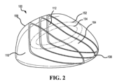
図1~図4は、可撓性ソール112を有するゴルフ・クラブ・ヘッド100の一実施形態を示す。ソール112は(接地面から離れるように)内向きに反るように設計されており、それにより、ゴルフ・ボールとの衝突時におけるゴルフ・クラブ・ヘッド100の柔軟性を増加させる高める。その増加が、より大きい内部エネルギーがゴルフ・クラブ・ヘッド100により生成されることをもたらす。内部エネルギーのこの増加は、ゴルフ・クラブ・ヘッド100により打たれたゴルフ・ボールのボール速度を上げる。より速いボール速度は、続いて、より遠くまで飛ぶゴルフ・ショットを直接的に意味する。内向きに反ったソールは、内向きに反ったソールを有していないゴルフ・クラブ・ヘッドより5ヤード~10ヤードだけ長い距離をもたらす。ゴルフ・クラブ・ヘッド100は、ゴルフ・クラブ・ヘッド100の柔軟性を抑制および制御する1つまたは複数の高剛性化梁290を更に備え得る。
1-4 illustrate one embodiment of a
I.内向きに反ったゴルフ・クラブ・ヘッド
図1~図4は、ボディ102とストライク・フェース104とを有するゴルフ・クラブ・ヘッド100を示す。クラブ・ヘッド100のボディ102は、前端部106、前端部106の反対側にある後端部108、クラウン110、クラウン110の反対側にあるソール112、ヒール114、および、ヒール114の反対側にあるトウ116を含む。ゴルフ・クラブ・ヘッド100のソール112は、接地面113を備え、ゴルフ・ボールを打つためにゴルフ・クラブ・ヘッド100がアドレス位置にあるとき、接地面113がソール112に接する。
I. Inwardly Curved Golf Club Head FIGS. 1-4 illustrate a
クラブ・ヘッド100は中空ボディ・クラブ・ヘッドである。ゴルフ・クラブ・ヘッド100は、ボディ102と、ストライク・フェース104と、を備える。ボディ102とストライク・フェース104は、ゴルフ・クラブ・ヘッド100の内部空洞118(図4)を規定する。示される実施形態において、ボディ102は、クラウン110と、ソール112と、ヒール114と、トウ116と、後端部108と、クラブ・ヘッド100の前端部106の外縁部120(図3)を更に規定する。これらの特徴は、中空ボディを更に規定し得る。ボディ102の外縁部120は、クラブ・ヘッド100の前端部106において、開口122を更に規定し、ストライク・フェース104は、開口122を塞ぐように外縁部120に結合されており、これにより、クラブ・ヘッド100を形成している。他の実施形態(図示省略)において、ストライク・フェース104は、クラブ・ヘッドの前端部106の全体にわたって広がり得、クラウン110と、ソール112と、ヒール114と、トウ116のうちの少なくとも1つにわたって広がる戻り部を含み得る。これらの実施形態において、ストライク・フェース104の戻り部は、クラブ・ヘッド100を形成するようにボディ102に結合されている。
図3に示されるように、クラブ・ヘッド100は、ホーゼル構造物124と、ホーゼル構造物124の孔に沿って中央に延びたホーゼル軸126と、を更に備える。ホーゼル構造物124は、ゴルフ・シャフト(図示省略)の端部に結合され得る。ゴルフ・シャフトは、ホーゼル軸126に対して複数の角度でホーゼル構造物124に固定され得る。しかし、シャフトがホーゼル構造物124に調節不能に固定され得る他の例が存在し得る。
As shown in FIG. 3,
クラブ・ヘッド100は、深さ140と、長さ142と、高さ144を規定している。図4を参照すると、クラブ・ヘッド100の深さ140は、Z軸1016と平行な方向において、前端部106から後端部108までのクラブ・ヘッド100の最も離れた範囲として測定され得る。
クラブ・ヘッド100の長さ142は、正面図(図3)から見たときに、X軸1012と平行な方向において、ヒール114からトウ116までのクラブ・ヘッド100の最も離れた範囲として測定され得る。多くの実施形態において、クラブ・ヘッド100の長さ142は、ゴルフ管理組織、例えば全米ゴルフ協会(USGA:the United States Golf Association)に従って測定され得る。例えば、クラブ・ヘッド100の長さ142は、ウッド・クラブのクラブ・ヘッド・サイズを測定するためのUSGAの手順に従って特定され得る(USGA-TPX3003、Rev.2.1、2019年4月9日)。
クラブ・ヘッド100の高さ144は、正面図(図3)から見たときに、Y軸1014と平行な方向において、クラウン110からソール112までのクラブ・ヘッド100の最も離れた範囲として測定され得る。多くの実施形態において、クラブ・ヘッド100の高さ144は、ゴルフ管理組織、例えば全米ゴルフ協会(USGA)に従って測定され得る。例えば、クラブ・ヘッド100の高さ144は、ウッド・クラブのクラブ・ヘッド・サイズを測定するためのUSGAの手順に従って特定され得る。
The
多くの実施形態において、クラブ・ヘッド100の容積(V)は、約150ccより大きい、約160ccより大きい、約170ccより大きい、約170ccより大きい、約180ccより大きい、約190ccより大きい、または、約195ccより大きい。幾つかの実施形態において、クラブ・ヘッドの容積(V)は、約150cc~198cc、160cc~198cc、170cc~198cc、約180cc~198cc、または約190cc~199ccであり得る。
In many embodiments, the volume (V) of the
更に、多くの実施形態において、クラブ・ヘッド100の容積は、約400ccより大きい、約425ccより大きい、約450ccより大きい、約475ccより大きい、約500ccより大きい、約525ccより大きい、約550ccより大きい、約575ccより大きい、約600ccより大きい、約625ccより大きい、約650ccより大きい、約675ccより大きい、または約700ccより大きい。幾つかの実施形態において、クラブ・ヘッド100の容積は、約400cc~600cc、425cc~500cc、約500cc~600cc、約500cc~650cc、約550cc~700cc、約600cc~650cc、約600cc~700cc、または約600cc~800ccであり得る。
Further, in many embodiments, the volume of the
続けて図3を参照すると、クラブ・ヘッド100のストライク・フェース104は、中心点または幾何学的中心128を規定する。幾つかの実施形態において、幾何学的中心128は、ストライク・フェース外縁130の幾何学的中心点に、および、フェース高さ132の中点に位置し得る。同じまたは他の例において、幾何学的中心128は、更に、ストライク・フェース104における溝136の領域により規定され得る設計された衝突ゾーン134に対して中心に位置し得る。別のアプローチとして、ストライク・フェース104の幾何学的中心128は、ゴルフ管理組織、例えば全米ゴルフ協会(USGA)の定義に従い得る。例えば、ストライク・フェース104の幾何学的中心128は、ゴルフ・クラブ・ヘッドの柔軟性を測定するためのUSGAの手順のセクション2.1に従って特定され得る(USGA-TPX3004、Rev.2.0、2019年4月9日)。
With continued reference to FIG. 3, the
図3および図4を参照すると、クラブ・ヘッド100は、ストライク・フェース104の幾何学的中心128に接したロフト平面1010を更に規定する。フェース高さ132は、クラウン110付近のストライク・フェース外縁130の上部端部とソール112付近のストライク・フェース外縁130の底部端部との間において、ロフト平面1010に平行に測定され得る。
3 and 4,
ストライク・フェース104の幾何学的中心128は、ストライク・フェース104の幾何学的中心128に位置する原点をもつゴルフ・クラブ・ヘッド100の座標系を更に規定する。座標系は、X軸1012と、Y軸1014と、Z軸1016と、を更に備える。X軸1012は、クラブ・ヘッド100のヒール114からトウ116に向かう方向にストライク・フェース104の幾何学的中心128を通って延びている。Y軸1014は、クラブ・ヘッド100のクラウン110からソール112に向かう方向にストライク・フェース104の幾何学的中心128を通って延びており、X軸1012に直交している。Z軸1016は、クラブ・ヘッド100の前端部106から後端部108に向かう方向にストライク・フェース104の幾何学的中心128を通って延びており、X軸1012とY軸1014に直交している。
The
座標系は、X軸1012とY軸1014を通って延びたXY平面1018、X軸1012とZ軸1016を通って延びたXZ平面1020、および、Y軸1014とZ軸1016を通って延びたYZ平面1022を規定する。XY平面1018と、XZ平面1020と、YZ平面1022はすべて、互いに直交しており、ストライク・フェース104の幾何学的中心128に位置する座標系の原点において交差している。XY平面1018は、ホーゼル軸126に平行に延びており、ロフト平面1010からクラブ・ヘッド100のロフト角度138に対応した角度で位置している。更に、X軸1012は、XY平面1018に直交する方向から(すなわち、図4において見られるように)見られた場合、ホーゼル軸126に対して約60度の角度で位置している。他の実施形態において、X軸1012は、XY平面1018に直交する方向から見られた場合ホーゼル軸126に対して45度~70度の角度で位置し得る。
The coordinate system includes an
これらの実施形態または他の実施形態において、ストライク・フェース104がXY平面1018に直交する方向から見られる場合、クラブ・ヘッド100は、(例えば図3に示されるような)正面図から見られ得る。更に、これらの実施形態または他の実施形態において、ヒール114がYZ平面1022に直交する方向から見られる場合、クラブ・ヘッド100は、側面図または側面断面図(例えば図4に示されるような)から見られ得る。
In these or other embodiments, when the
図3および図4に示されるように、クラブ・ヘッド100は、ヘッド重心(CG:center of gravity)146と、ヘッド深さ平面1024と、を更に備える。ヘッド深さ平面1024は、クラブ・ヘッド100のヒール114からトウ116に向かう方向において、ロフト平面1010に直交しており、ストライク・フェース104の幾何学的中心128を通って延びている。多くの実施形態において、ヘッドCG146は、XY平面1018からのヘッドCG深さに位置し、XY平面1018に直交する方向に測定される。幾つかの実施形態において、ヘッドCG146は、ロフト平面1010からのヘッドCG深さ148に位置し、ロフト平面1010に直交した方向に測定され得る。ヘッドCG146は、ヘッド深さ平面1024からのヘッドCG高さ150に更に位置し、ヘッド深さ平面1024に直交する方向に測定される。更に、ヘッドCG高さ150は、クラウン110に向かっており、またはソール112に向かっているヘッド深さ平面1024に直交する方向において、ヘッド深さ平面1024からのオフセット距離として測定される。多くの実施形態において、ヘッドCG146がヘッド深さ平面1024の上方に(すなわち、ヘッド深さ平面1024とクラウン110との間に)位置しているとき、ヘッドCG高さ150は、正の値であり、ヘッドCG146がヘッド深さ平面1024の下方に(すなわち、ヘッド深さ平面1024とソール112との間に)位置しているとき、ヘッドCG高さ150は、負の値である。幾つかの実施形態において、ヘッドCG高さ150の絶対値は、ヘッド深さ平面1024の上方または下方に(すなわち、ヘッド深さ平面1024とクラウン110との間に、または、ヘッド深さ平面1024とソール112との間に)位置しているヘッドCG146を説明し得る。多くの実施形態において、ヘッドCG146は、クラブ・ヘッド100のソール112および後端部108に向けて戦略的に配置される。
As shown in FIGS. 3 and 4,
ヘッドCG146は、X’軸1026と、Y’軸1028と、Z’軸1030を有する座標系の原点を規定する。Y’軸1028は、側面図から見られた場合、ホーゼル軸126に平行に、正面図から見られた場合(すなわち、図3において見られるように)、ホーゼル軸126に対して30度の角度で、ヘッドCG146を通ってクラウン110からソール112まで延びている。X’軸1026は、ヘッドCG146を通ってヒール114からトウ116まで延びており、正面図から見られたときY’軸1028に直交して、および、XY平面1018に平行に延びている。Z’軸1030は、ヘッドCG146を通って前端部106から後端部108まで延びており、X’軸1026とY’軸1028に直交して延びている。多くの実施形態において、X’軸1026は、ヘッドCG146を通ってヒール114からトウ116まで、X軸1012に平行に延びている。Y’軸1028は、Y軸1014に平行に、ヘッドCG146を通ってクラウン110からソール112まで延びている。Z’軸1030は、ヘッドCG146を通って前端部106から後端部108まで、Z軸1016に平行に延びている。
上記の例はウッド・タイプのゴルフ・クラブ100に関連して説明されている場合があるが、本明細書において説明されている装置、方法、および製品は、ドライバ、フェアウェイ・ウッド、ハイブリッド、クロスオーバー、または任意の中空ボディ・タイプのゴルフ・クラブを含む様々なタイプのゴルフ・クラブに適用可能であってもよい。
Although the above examples may be described in connection with a wood-
クラブ・ヘッド100は、ロフト平面1010と接地面113との間の角度として測定されたロフト角度(図示されていない)を更に備える。多くの実施形態において、ロフト角度は、約7度から40度の間の範囲にある。幾つかの実施形態において、クラブ・ヘッド100のロフト角度は、約16度未満、約15度未満、約14度未満、約13度未満、約12度未満、約11度未満、または、約10度未満である。
多くの実施形態において、クラブ・ヘッド100のロフト角度は、約35度未満、約34度未満、約33度未満、約32度未満、約31度未満、または約30度未満である。更に、多くの実施形態において、クラブ・ヘッド100のロフト角度は、約12度より大きい、約13度より大きい、約14度より大きい、約15度より大きい、約16度より大きい、約17度より大きい、約18度より大きい、約19度より大きい、または約20度より大きい。例えば、幾つかの実施形態において、クラブ・ヘッド100のロフト角度は、12度から35度の間、15度から35度の間、20度から35度の間、または12度から30度の間であり得る。
In many embodiments, the loft angle of
多くの実施形態において、クラブ・ヘッド100のロフト角度は、約40度未満、約39度未満、約38度未満、約37度未満、約36度未満、約35度未満、約34度未満、約33度未満、約32度未満、約31度未満、または約30度未満である。更に、多くの実施形態において、クラブ・ヘッド100のロフト角度は、約16度より大きい、約17度より大きい、約18度より大きい、約19度より大きい、約20度より大きい、約21度より大きい、約22度より大きい、約23度より大きい、約24度より大きい、または約25度より大きい。
In many embodiments, the loft angle of the
クラブ・ヘッド100のストライク・フェース104は、第1の材料から形成されている。多くの実施形態において、第1の材料は、金属合金、例えば、チタン合金(例えば、Ti 7-4、Ti 6-4、T-9S、Ti SSAT2041、Ti SP700、Ti 15-0-3、Ti 15-5-3、Ti 3-8-6-4-4、Ti 10-2-3、Ti 15-3-3-3、Ti-6-6-2、Ti-185、HST-180など、または、それらの任意の組合せ)、鋼合金(例えば、C300鋼、C350鋼、455鋼、431鋼、475鋼、565鋼、17-4ステンレス鋼、マルエージング鋼、Ni-Co-Cr鋼合金など)、アルミニウム合金、または、任意の他の金属もしくは金属合金であり得る。他の実施形態において、第1の材料は、別の材料、例えば、複合材料、プラスチック、熱可塑性複合材料、または、任意の他の適切な材料もしくは材料の組合せであり得る。
クラブ・ヘッド100のボディ102は第2の材料から形成されている。多くの実施形態において、第1の材料は、金属合金、例えば、チタン合金(例えば、Ti 7-4、Ti 6-4、T-9S、Ti SSAT2041、Ti SP700、Ti 15-0-3、Ti 15-5-3、Ti 3-8-6-4-4、Ti 10-2-3、Ti 15-3-3-3、Ti-6-6-2、Ti-185など、または、それらの任意の組合せ)、鋼合金(例えば、C300鋼、C350鋼、455鋼、431鋼、475鋼、565鋼、17-4ステンレス鋼、マルエージング鋼、Ni-Co-Cr鋼合金など)、アルミニウム合金、または、任意の他の金属もしくは金属合金であり得る。他の実施形態において、第1の材料は、別の材料、例えば、複合材料、プラスチック、または、任意の他の適切な材料もしくは材料の組合せであり得る。示される実施形態において、第2の材料は、第1の材料と異なる。他の実施形態において、第1の材料と第2の材料とは同じであり得る。
II.逆反りソール
図2を参照すると、ゴルフ・クラブ・ヘッド100のソール112は、ソール112が内部空洞118(図4)に向かう方向に内側に曲がったへこみ、またはへこんだ領域152を更に含む。XZ平面1020(図4)に関連して、へこんだ領域152は、XZ平面1020に対して凸状の逆反り領域154を含む。典型的な従来技術のメタルウッドは、同等なXZ平面に対して凹状でのみあるソール・プロファイルを含む。したがって、典型的な従来技術のメタルウッドは、前端部と後端部との間に比較的大きい曲率半径(すなわち、約22インチ~25インチの曲率半径)を有するソール・プロファイルを含む。対照的に、ゴルフ・クラブ・ヘッド100のへこんだ領域152は、ソール112が、前端部106と後端部108との間においてはるかに急に湾曲したプロファイルに沿うことを可能にする。例えば、クラブ・ヘッド100の幾つかの実施形態では、(例えば図4において見られるように)YZ平面1022に沿って取得された側面断面図から見られた場合、YZ平面1022により切断されたソール112のどの部分も前端部106と後端部108との間に10インチより大きい曲率半径を含まない。
II. Reverse Curved Sole Referring to FIG. 2, the sole 112 of the
更に、クラブ・ヘッド100の示される実施形態において、YZ平面1022に沿って取得された側面断面図から見られた場合、ソール112のどの部分も6インチより大きい曲率半径を含まない。ソール112にへこんだ領域152を実装することにより、前端部106と後端部108との間においてソール112の比較的小さい曲率半径を達成し、、クラブ・ヘッド・ボディ102は、ゴルフ・ボールとの衝突中に、ソール112においてより大きい変形を受ける。これは、ゴルフ・クラブ・ヘッド100のたわみの増加と、衝突中におけるクラブ・ヘッド100からボールへの、より効率的なエネルギー伝達をもたらす。ソール112の湾曲は、以下で更に詳細に説明される。
Further, in the illustrated embodiment of
図4を参照すると、クラブ・ヘッド100は、前端部106がソール112に遷移するフェース・ソール遷移境界156(図2)を含む。フェース・ソール遷移境界156は、前端部106とソール112との間においてヒール114付近からトウ116付近まで延びている。フェース・ソール遷移プロファイル158は、フェース・ソール遷移境界156がYZ平面1022により切断された場所に規定される。すなわち、フェース・ソール遷移プロファイル158は、(例えば図4において見られるように)YZ平面1022に沿って取得された側面断面図から見られた場合に見えるように、YZ平面1022により切断されたフェース・ソール遷移境界156の線状部分である。
Referring to FIG. 4,
フェース・ソール遷移プロファイル158は、フェース・ソール遷移曲率半径R1に沿っている。フェース・ソール遷移プロファイル158は、ストライク・フェース104の外形がストライク・フェース104のロール半径から逸脱しているストライク・フェース遷移点160からソール遷移点162まで延びており、ソール遷移点162において、ソール112の湾曲がフェース・ソール遷移曲率半径R1から逸脱している。ソール遷移点162は、ストライク・フェース104とソール112との交差部により規定されている。幾つかの実施形態において、フェース・ソール遷移曲率半径R1は、ストライク・フェース遷移点160からソール遷移点162にわたって一定の曲率半径をもつ。
Face-to-
幾つかの実施形態において、フェース・ソール遷移曲率半径R1は、約0.10インチから0.50インチの範囲であり得る。例えば、フェース・ソール遷移曲率半径R1は、約0.5インチ未満、約0.475インチ未満、約0.45インチ未満、約0.425インチ未満、または、約0.40インチ未満であり得る。更なる例において、フェース・ソール遷移曲率半径R1は、約0.10インチ、0.15インチ、0.20インチ、0.25インチ、0.30インチ、0.35インチ、0.40インチ、0.45インチ、または0.50インチであり得る。 In some embodiments, the face-sole transition radius of curvature R1 may range from about 0.10 inch to 0.50 inch. For example, the face-sole transition radius R1 can be less than about 0.5 inch, less than about 0.475 inch, less than about 0.45 inch, less than about 0.425 inch, or less than about 0.40 inch. . In further examples, the face-sole transition radius R1 is about 0.10 inches, 0.15 inches, 0.20 inches, 0.25 inches, 0.30 inches, 0.35 inches, 0.40 inches, It can be 0.45 inch, or 0.50 inch.
続けて図4を参照すると、ソール112は、前端部106から後端部108まで、およびヒール114からトウ116まで延びた外部ソール表面164(図2)を規定する。クラブ・ヘッド100のソール湾曲プロファイル166は、YZ平面1022により切断され、かつソール遷移点162から後端部108まで延びたソール表面164の線状の範囲として規定されている。ソール湾曲プロファイル166は、第1の凹セクション168と、凸セクション170と、第2の凹セクション172を含む。第1の凹セクション168は、ソール遷移点162から第1の変曲点174まで延びており、XZ平面1020に対して凹状である(接地面113に対して凸状である)。第1の変曲点174は、前端部106から後端部108に向かってソール湾曲プロファイル166をたどるとき、ソール湾曲プロファイル166に沿っており、ソール湾曲プロファイル166がXZ平面1020に対して凹部を反転させる第1の点として規定される。
With continued reference to FIG. 4, sole 112 defines an external sole surface 164 (FIG. 2) that extends from
ソール湾曲プロファイル166の凸セクション170は、第1の変曲点174から第2の変曲点176まで延びており、XZ平面1020に対して凸状である(接地面113に対して凹状である)。第2の変曲点176は、前端部106から後端部108に向かってソール湾曲プロファイル166をたどるとき、ソール湾曲プロファイル166に沿っており、ソール湾曲プロファイル166がXZ平面1020に対して凹部を反転させる第2の点として規定される。ソール湾曲プロファイル166の第2の凹セクション172は、第2の変曲点176から後端部108まで延びており、XZ平面1020に対して凹状である(接地面113に対して凸状である)。
A
続けて図4を参照すると、クラブ・ヘッド100は、ロフト平面1010と第1の変曲点174との間においてロフト平面1010に直交した方向に沿って測定された第1の変曲点深さ178を更に含む。多くの実施形態において、クラブ・ヘッド100の第1の変曲点深さ178は、0.50インチより大きい。示される実施形態において、第1の変曲点深さ178は約、1.50インチである。他の実施形態において、クラブ・ヘッド100の第1の変曲点深さ178は、0.75インチより大きい、1.00インチより大きい、1.10インチより大きい、1.20インチより大きい、1.30インチより大きい、1.40インチより大きい、1.50インチより大きい、1.60インチより大きい、1.70インチより大きい、1.80インチより大きい、1.90インチより大きい、2.00インチより大きい、2.25インチより大きい、または2.50インチより大きい。例えば、幾つかの実施形態において、クラブ・ヘッド100の第1の変曲点深さ178は、0.50インチ~2.50インチの間、1.00インチ~2.00インチの間、1.25インチ~1.75インチの間、1.35インチ~1.65インチの間、または1.45インチ~1.55インチの間であり得る。幾つかの実施形態において、クラブ・ヘッド100の第1の変曲点深さ178は、0.50インチ、0.75インチ、1.0インチ、1.25インチ、1.50インチ、1.75インチ、2.00インチ、2.25インチ、または2.50インチであり得る。
With continued reference to FIG. 4, the
クラブ・ヘッド100の第1の変曲点深さ比は、クラブ・ヘッド100の深さ140に対する第1の変曲点深さ178の比として規定される。多くの実施形態において、第1の変曲点深さ比は、0.25より大きい。他の実施形態において、第1の変曲点深さ比は、0.30より大きい、0.31より大きい、0.32より大きい、0.33より大きい、0.34より大きい、0.35より大きい、0.36より大きい、0.37より大きい、0.38より大きい、0.39より大きい、0.40より大きい、または0.45より大きい。例えば、幾つかの実施形態において、クラブ・ヘッド100の第1の変曲点深さ比は、0.25~0.45の間、0.30~0.45の間、0.25~0.40の間、0.30~0.40の間、0.32~0.38の間、または0.34~0.36の間であり得る。幾つかの実施形態において、クラブ・ヘッド100の第1の変曲点深さ比は、0.25、0.26、0.27、0.28、0.29、0.30、0.31、0.32、0.33、0.34、0.35、0.36、0.37、0.38、0.39、0.40、0.41、0.42、0.43、0.44、または0.45であり得る。
The first inflection point depth ratio of the
続けて図4を参照すると、クラブ・ヘッド100のソール112は、奥部180を更に規定する。奥部180は、へこんだ領域152(図2)を通って延びたソール湾曲プロファイル166の断面に沿って位置している。特に、奥部180は、へこんだ領域152内でおよびXZ平面1020に最も近くでソール湾曲プロファイル166に位置する点として規定される。ほとんどの実施形態において、奥部180は、凸セクション170に位置している。言い換えると、奥部180は、へこんだ領域152が内部空洞118に向かって延びるときのへこんだ領域152の最低点を表す。
With continued reference to FIG. 4, the sole 112 of the
クラブ・ヘッド100は、奥部高さ(図示省略)を更に含み、奥部高さは、接地面113から奥部180まで垂直に測定される。多くの実施形態において、クラブ・ヘッド100の奥部高さは、0.01インチから0.30インチの間の範囲にある。他の実施形態において、クラブ・ヘッド100の奥部高さは、0.01インチ~0.05インチ、0.05インチ~0.10インチ、0.10インチ~0.15インチ、0.15インチ~0.20インチ、0.20インチ~0.25インチ、または0.25インチ~0.30インチの間の範囲であり得る。他の実施形態において、奥部高さは、0.01インチ、0.02インチ、0.03インチ、0.04インチ、0.05インチ、0.06インチ、0.07インチ、0.08インチ、0.09インチ、0.10インチ、0.11インチ、0.12インチ、0.13インチ、0.14インチ、0.15インチ、0.16インチ、0.17インチ、0.18インチ、0.19インチ、0.20インチ、0.21インチ、0.22インチ、0.23インチ、0.24インチ、0.25インチ、0.26インチ、0.27インチ、0.28インチ、0.29インチ、または0.30インチであり得る。
クラブ・ヘッド100は、ロフト平面1010と奥部180との間においてロフト平面1010に直交した方向に沿って測定された奥部深さ182を更に含む。多くの実施形態において、クラブ・ヘッド100の奥部深さ182は、1.5インチより大きい。他の実施形態において、クラブ・ヘッド100の奥部深さ182は、1.6インチより大きい、1.7インチより大きい、1.8インチより大きい、1.9インチより大きい、2.0インチより大きい、2.1インチより大きい、2.2インチより大きい、2.3インチより大きい、2.4インチより大きい、または2.5インチより大きい。例えば、幾つかの実施形態において、クラブ・ヘッド100の奥部深さ182は、1.5インチ~3.0インチの間、1.5インチ~2.5インチの間、2.0インチ~3.0インチの間、2.0インチ~2.5インチの間、または2.5インチ~3.0インチの間であり得る。
クラブ・ヘッド100の奥部深さ比は、クラブ・ヘッド100の深さ140に対する奥部深さ182の比として規定される。多くの実施形態において、奥部深さ比は、0.35より大きい。他の実施形態において、奥部深さ比は、0.40より大きい、0.45より大きい、0.46より大きい、0.47より大きい、0.48より大きい、0.49より大きい、0.50より大きい、0.51より大きい、0.52より大きい、0.53より大きい、0.54より大きい、0.55より大きい、または0.60より大きい。例えば、幾つかの実施形態において、クラブ・ヘッド100の奥部深さ比Bは、0.40~0.60の間、0.45~0.60の間、0.40~0.55の間、0.45~0.55の間、0.47~0.53の間、または0.49~0.51の間であり得る。
The depth ratio of
クラブ・ヘッド100のソール湾曲プロファイル166は、前端部106と後端部108との間におけるソール湾曲プロファイル166の様々なセクションの各々に沿った曲率半径の観点から更に説明され得る。図4を参照すると、ソール湾曲プロファイル166の第1の凹セクション168は、第1のセクション曲率半径R2を有する第1の湾曲セクション184と、第2のセクション曲率半径R3を有する第2の湾曲セクション186に分割される。第1の湾曲セクション184は、ソール遷移点162から、第1の凹セクション遷移点188まで延びている。第1の凹セクション遷移点188は、第1のセクション曲率半径R2が第2のセクション曲率半径R3に遷移するソール湾曲プロファイル166に沿った点として規定されている。第2の湾曲セクション186は、第1の凹セクション遷移点188から、凸セクション170から第2の湾曲セクション186を分割する第1の変曲点174まで延びている。ソール湾曲プロファイル166の凸セクション170は、凸セクション曲率半径R4を含む。最後に、第2の凹セクション172は、第2の凹セクション曲率半径R5を含む。
The
幾つかの実施形態において、第1のセクション曲率半径R2は、約1.00インチから3.50インチの範囲であり得る。示される実施形態において、第1のセクション曲率半径R2は、約1.75インチである。他の実施形態において、第1のセクション曲率半径R2は、3.00インチ未満、2.50インチ未満、2.25インチ未満、2.00インチ未満、または1.75インチ未満であり得る。例えば、第1のセクション曲率半径R2は、約1.00インチ、1.25インチ、1.5インチ、1.75インチ、2.00インチ、2.25インチ、または2.50インチであり得る。 In some embodiments, the first section radius of curvature R2 can range from about 1.00 inches to 3.50 inches. In the embodiment shown, the first section radius of curvature R2 is approximately 1.75 inches. In other embodiments, the first section radius of curvature R2 can be less than 3.00 inches, less than 2.50 inches, less than 2.25 inches, less than 2.00 inches, or less than 1.75 inches. For example, the first section radius of curvature R2 can be approximately 1.00 inches, 1.25 inches, 1.5 inches, 1.75 inches, 2.00 inches, 2.25 inches, or 2.50 inches. .
幾つかの実施形態において、第2のセクション曲率半径R3は、約1.0インチから10.0インチの範囲であり得る。一実施形態において、第2のセクション曲率半径R3は、約6.0インチである。他の実施形態において、第2のセクション曲率半径R3は、9.0インチ未満、8.0インチ未満、7.0インチ未満、6.0インチ未満、5.0インチ未満、4.0インチ未満、3.0インチ未満、または2.0インチ未満であり得る。例えば、第2のセクション曲率半径R3は、約3.0インチ、4.0インチ、5.0インチ、6.0インチ、7.0インチ、8.0インチ、または9.0インチであり得る。 In some embodiments, the second section radius of curvature R3 may range from approximately 1.0 inches to 10.0 inches. In one embodiment, the second section radius of curvature R3 is approximately 6.0 inches. In other embodiments, the second section radius of curvature R3 is less than 9.0 inches, less than 8.0 inches, less than 7.0 inches, less than 6.0 inches, less than 5.0 inches, less than 4.0 inches. , less than 3.0 inches, or less than 2.0 inches. For example, the second section radius of curvature R3 can be approximately 3.0 inches, 4.0 inches, 5.0 inches, 6.0 inches, 7.0 inches, 8.0 inches, or 9.0 inches. .
クラブ・ヘッド100の奥部高さ比は、第1の凹セクション168の曲率半径R3に対する奥部高さの比として規定される。奥部高さは、曲率半径R3に反比例する。曲率半径R3の大きさが小さくなるにつれて、奥部高さが高くなる。曲率半径R3の大きさが大きくなるにつれて、奥部高さが低くなる。多くの実施形態において、奥部高さ比は、0.33以下である。他の実施形態において、奥部高さ比は、0.30未満、0.25未満、0.20未満、0.15未満、0.10未満、または0.05未満である。他の実施形態において、奥部高さ比は、0.001~0.05、0.05~0.10、0.10~0.15、0.15~0.20、0.20~0.25、0.25~0.30、または0.30~0.33の間の範囲であり得る。
The back height ratio of the
幾つかの実施形態において、凸セクション曲率半径R4は、約1.0インチから9.0インチの範囲であり得る。一実施形態において、凸セクション曲率半径R4は、約2.5インチである。他の実施形態において、凸セクション曲率半径R4は、8.0インチ未満、7.0インチ未満、6.0インチ未満、5.0インチ未満、4.0インチ未満、3.5インチ未満、3.0インチ未満、または2.5インチ未満であり得る。例えば、凸セクション曲率半径R4は、約1.0インチ、2.0インチ、2.5インチ、3.0インチ、4.0インチ、5.0インチ、6.0インチ、7.0インチ、8.0インチ、または9.0インチであり得る。 In some embodiments, the convex section radius of curvature R4 can range from about 1.0 inches to 9.0 inches. In one embodiment, the convex section radius of curvature R4 is approximately 2.5 inches. In other embodiments, the convex section radius of curvature R4 is less than 8.0 inches, less than 7.0 inches, less than 6.0 inches, less than 5.0 inches, less than 4.0 inches, less than 3.5 inches, 3 It can be less than .0 inch, or less than 2.5 inches. For example, the convex section radius of curvature R4 is approximately 1.0 inch, 2.0 inch, 2.5 inch, 3.0 inch, 4.0 inch, 5.0 inch, 6.0 inch, 7.0 inch, It can be 8.0 inches or 9.0 inches.
幾つかの実施形態において、第2の凹セクション曲率半径R5は、約3.0インチから10.0インチの範囲であり得る。示される実施形態において、第2の凹セクション曲率半径R5は、約6.0インチである。他の実施形態において、第2の凹セクション曲率半径R5は、9.0インチ未満、8.0インチ未満、7.0インチ未満、6.0インチ未満、または5.0インチ未満であり得る。例えば、第2の凹セクション曲率半径R5は、約3.0インチ、4.0インチ、5.0インチ、6.0インチ、7.0インチ、8.0インチ、または9.0インチであり得る。他の実施形態において、クラブ・ヘッド100のソール湾曲プロファイル166は、多項式、または二次式によっても決定され得る。
In some embodiments, the second concave section radius of curvature R5 can range from about 3.0 inches to 10.0 inches. In the embodiment shown, the second concave section radius of curvature R5 is approximately 6.0 inches. In other embodiments, the second concave section radius of curvature R5 can be less than 9.0 inches, less than 8.0 inches, less than 7.0 inches, less than 6.0 inches, or less than 5.0 inches. For example, the second concave section radius of curvature R5 may be approximately 3.0 inches, 4.0 inches, 5.0 inches, 6.0 inches, 7.0 inches, 8.0 inches, or 9.0 inches. obtain. In other embodiments, the
上述のようなへこんだ領域152は、クラブ・ヘッド100のソール112が従来技術のメタルウッド・クラブ・ヘッドに比べて、前端部106と後端部108との間においてはるかに急に湾曲したプロファイルに沿うことを可能にする(すなわち、ソール湾曲プロファイルが前端部と後端部との間に延びるのに伴い10インチより大きい曲率半径となる)。これは、クラブ・ヘッド100がゴルフ・ボールに衝突するときに、クラブ・ボディ102のソール112において、より大きいたわみを生じやすくする。クラブ・ボディ102の比較的大きいたわみは、従来のメタルウッド・ゴルフ・クラブに比べて、クラブ・ヘッド100のより大きいたわみをもたらし得る。
The recessed
ゴルフ・クラブ・ヘッド100は、衝突時に生成される内部エネルギーを、比較対象のクラブを超える1.0lbfインチ~8.0lbfインチの間へと高め得る。幾つかの実施形態において、ゴルフ・クラブ・ヘッド200により衝突時に生成される内部エネルギーは、1.0lbfインチ、2.0lbfインチ、3.0lbfインチ、4.0lbfインチ、5.0lbfインチ、6.0lbfインチ、7.0lbfインチ、または8.0lbfインチであり得る。内部エネルギーのこの大幅な増加は、0.1mph、0.2mph、0.3mph、0.4mph、0.5mph、0.6mph、0.7mph、0.8mph、0.9mph、1.0mph、1.1mph、1.2mph、1.3mph、1.4mph、または1.5mphだけ増加したボール速度もたらし、これにより、1ヤード~10ヤードの間でゴルフ・ボールの飛距離の増加をもたらし得る。幾つかの実施形態において、ゴルフ・ボールの飛距離は、1ヤード、2ヤード、3ヤード、4ヤード、5ヤード、6ヤード、7ヤード、8ヤード、9ヤード、または10ヤード増加し得る。
The
更に、衝突中におけるソール112の比較的大きいたわみは、クラブ・ヘッド100との衝突時にゴルフ・ボールに生じるボール・スピン速度の低下をもたらし得る。例えば、スピン速度は、毎分約150回転(RPM:revolutions per minute)だけ低下させられ得る。幾つかの実施形態において、スピン速度は、10RPM、20RPM、30RPM、40RPM、50RPM、60RPM、70RPM、80RPM、90RPM、100RPM、110RPM、120RPM、130RPM、140RPM、または150RPMだけ低下させられ得る。幾つかの例において、ボール・スピン速度は、160RPM、170RPM、180RPM、190RPM、または、更には、200RPMだけ低下させられ得る。
Additionally, the relatively large deflection of the sole 112 during impact may result in a reduction in the ball spin rate experienced by the golf ball upon impact with the
III.逆反りソールおよび内部湾曲梁
図5~図7は、本発明の別の実施形態によるゴルフ・クラブ・ヘッド200を示す。ゴルフ・クラブ・ヘッド200は、ゴルフ・クラブ・ヘッド100と同様であり、ゴルフ・クラブ・ヘッド100と実質的に同じ構造を含む。したがって、以下の説明は、図1~図4に関連した上述の実施形態と異なる構造および特徴に主に焦点を置く。図1~図4に関連して説明されている特徴および要素は、図5~図7において200番台の参照符号を付されている。以下で明示的に説明されていないゴルフ・クラブ・ヘッド200の特徴は、ゴルフ・クラブ・ヘッド100の特徴と同じ性質を有することが理解されなければならない。
III. Reverse Cave Sole and Internally Curved Beam FIGS. 5-7 illustrate a
ゴルフ・クラブ・ヘッド100と同様に、ゴルフ・クラブ・ヘッド200は、ソール212に形成されたへこんだ領域252(図5)を含む。図5および図6を参照すると、ゴルフ・クラブ・ヘッド200は、第1の端部291において、および第2の端部292においてソール212に装着され、第1の端部291と第2の端部292との間においてゴルフ・クラブ・ヘッド200の内部空洞218を通って延びた内部梁290を更に含む。示される実施形態において、ゴルフ・クラブ・ヘッド200は、3つの梁290を含む。他の実施形態において、ゴルフ・クラブ・ヘッド200は、1つ、2つ、4つ、5つ、6つ、7つ、8つ、9つまたは10個の梁290を含み得る。
Similar to
各梁290の第1の端部291は、ゴルフ・クラブ・ヘッド200の前端部206に近接した位置においてソール212に装着されている。例えば、示される実施形態において、第1の端部291は、フェース・ソール遷移境界256に近接したソール212の一部に装着されている。各梁290の第2の端部292は、へこんだ領域252に、またはへこんだ領域252の近くにおいてソール212に装着されている。
A
各梁290は、略前後方向に、または略Z軸1016に沿った方向に延びている。幾つかの実施形態において、各梁290は、第1の端部291と第2の端部292との間において略直線の経路に沿う。示される実施形態では、各梁290は、第1の端部291と第2の端部292との間において曲線の経路に沿っている。特に、各梁290は、第1の端部291と第2の端部292との間において略弧形の経路に沿っている。更に、示される実施形態では、梁290は、互いに略平行に延びており、および、各梁290は、略同じ弧形の経路に沿っている。他の実施形態において、梁290は、第1の端部291と第2の端部292との間において、互いに異なるそれぞれの経路に沿い得る。
Each
各梁290の梁高さ293は、ソールの内面に直交するように測定された、梁290とソール212の内面との間の最大距離として規定される。梁高さ293は、0.010インチ~1.000インチの範囲であり得る。幾つかの実施形態において、梁高さ293は、0.010インチ~0.10インチ、0.10インチ~0.20インチ、0.20インチ~0.30インチ、0.30インチ~0.40インチ、0.40インチ~0.50インチ、0.50インチ~0.60インチ、0.60インチ~0.70インチ、0.70インチ~0.80インチ、0.80インチ~0.90インチ、または0.90インチ~1.0インチの間の範囲であり得る。幾つかの実施形態において、梁高さ293は、0.10インチ、0.20インチ、0.30インチ、0.40インチ、0.50インチ、0.60インチ、0.70インチ、0.80インチ、0.90インチ、または1.0インチであり得る。
The
図7を参照すると、各梁290は、梁290が梁290の経路に直交するように広がる平面により切断されるように規定された断面形状294を含む。示される実施形態において、各梁290の断面形状294は、長方形である。他の実施形態において、各梁290の断面形状294は、円形、三角形、長方形、台形、八角形、または任意の他の望ましい断面形状であってもよい。
Referring to FIG. 7, each
示される実施形態において、各梁290の断面形状294は、略ヒール・トウ方向に測定された幅295と、略クラウン・ソール方向に測定された厚さ296を含む。幅295は、約0.010インチ~1.000インチの範囲であり得る。幅295は、0.010インチ、0.05インチ、0.10インチ、0.20インチ、0.30インチ、0.40インチ、0.50インチ、0.60インチ、0.70インチ、0.80インチ、0.90インチ、または1.0インチであり得る。示される実施形態において、幅295は、約0.2インチである。
In the embodiment shown, the
厚さ296は、約0.010インチ~0.500インチの範囲であり得る。幾つかの実施形態において、厚さ296は、0.010インチ、0.015インチ、0.020インチ、0.025インチ、0.030インチ、0.035インチ、0.040インチ、0.045インチ、または0.050インチであり得る。示される実施形態において、厚さ296は、約0.033インチである。更に、各梁290は、近接した梁の各々から約0.5インチだけ離れている。
他の実施形態において、梁290は、0.050インチ~1.000インチの範囲の距離だけ互いに離れ得る。幾つかの実施形態において、梁290は、0.010インチ、0.015インチ、0.020インチ、0.025インチ、0.030インチ、0.035インチ、0.040インチ、0.045インチ、または0.050インチの距離だけ互いに離れ得る。
In other embodiments,
幾つかの実施形態において、梁290は、クラブ・ヘッド200のボディ204と同じ材料から形成され得、ボディ204と一体的に形成され得る。他の実施形態において、梁290は、ボディ204とは別に形成されて、例えば、溶接、樹脂接着、または任意の他の適切な連結方法といった連結方法によりボディ204に結合され得る。これらの実施形態において、梁290は、クラブ・ヘッド200のボディ204と同じまたは異なる材料から形成され得る。
In some embodiments,
図8および図9は、本発明の別の実施形態によるゴルフ・クラブ・ヘッド300を示す。ゴルフ・クラブ・ヘッド300は、ゴルフ・クラブ・ヘッド200と同様であり、ゴルフ・クラブ・ヘッド200と実質的に同じ構造を含む。したがって、以下の説明は、図5~図7に関連した上述の実施形態と異なる構造および特徴に主に焦点を置く。図5~図7に関連して説明されている特徴および要素は、図8および図9において300番台の参照符号を付されている。以下で明示的に説明されていないゴルフ・クラブ・ヘッド300の特徴は、ゴルフ・クラブ・ヘッド200の特徴と同じ性質を有することが理解されなければならない。
8 and 9 illustrate a
ゴルフ・クラブ・ヘッド100および200と同様に、ゴルフ・クラブ・ヘッド300は、ソール312に形成されたへこんだ領域352を含む。また、ゴルフ・クラブ・ヘッド200と同様に、ゴルフ・クラブ・ヘッド300は、第1の端部391と第2の端部392との間に延びた内部梁390を含む。しかし、ゴルフ・クラブ・ヘッド200と異なり、クラブ・ヘッド300の梁390の第1の端部391は、ソール312に装着されていない。各梁390の第1の端部391は、前端部306に装着されている。特に、各梁390の第1の端部391は、前端部306の外縁部320に装着されている。更に、示される実施形態において、クラブ・ヘッド300は、4つの梁390を含む。他の実施形態において、クラブ・ヘッド300は、1つ、2つ、3つ、5つ、6つ、7つ、8つ、9つまたは10個の梁290を含み得る。クラブ・ヘッド300の梁390は、クラブ・ヘッド200に関連した上述の経路のうちの任意のものに沿い得る。同様に、梁390は、クラブ・ヘッド200に関連した上述の梁高さ293、断面形状294、幅295、および厚さ296と同様の、梁高さ393、断面形状394、幅395、および厚さ396を含み得る。
Similar to golf club heads 100 and 200,
IV.例
例1:逆反りソールを含むゴルフ・クラブ・ヘッド
図10~図12を参照すると、ソール412がクラブ・ヘッド400の内部空洞418に向かう方向に内側に曲がっているへこみまたはへこんだ領域452を含むソール412を含むウッド・タイプのゴルフ・クラブ・ヘッド400が示される。したがって、典型的なウッドは、前端部と後端部との間に比較的大きい曲率半径(すなわち、約22~25インチの曲率半径)を有するソール・プロファイルを含む。対照的に、ゴルフ・クラブ・ヘッド400のへこんだ領域452は、ソール412が前端部406と後端部408との間においてはるかに急に湾曲したプロファイルに沿うことを可能にする。更に、クラブ・ヘッド400の示される実施形態において、ソール412のどの部分もYZ平面4022に沿って取得された側面断面図から見られた場合6インチより大きい曲率半径を含まない。
IV. Examples Example 1: Golf Club Head Including a Reverse Cave Sole Referring to FIGS. A wood-type
上述のへこんだ領域452は、このプロファイルを含まないメタルウッド・クラブ・ヘッドと比べると、クラブ・ヘッド400のソール412が前端部406と後端部408との間においてはるかに急に湾曲したプロファイルに沿うことを可能にする。これは、クラブ・ヘッド400がゴルフ・ボールに衝突するときにクラブ・ボディ402のソール412において、より大きいたわみを生じやすくする。クラブ・ボディ402のより大きいたわみは、へこんだ領域452を含まない従来のメタルウッド・ゴルフ・クラブと比べると、クラブ・ヘッド400内においてより多くの量の内部エネルギーを生成する。
The recessed
図13を参照すると、ゴルフ・クラブ・ヘッド400により衝突時に生成される内部エネルギーが、ソール(なお、ソール・プロファイルは、クラブの前端部と後端部との間に比較的大きい曲率半径を有する)にへこんだ領域を含まないゴルフ・クラブ・ヘッド(以下、「比較対象のクラブ」)により衝突時に生成される内部エネルギーと比較されている。ゴルフ・クラブ・ヘッド400のへこんだ領域452は、比較対象のクラブを超える約7.8lbfインチぶんのゴルフ・クラブ・ヘッド400の内部エネルギーの増加をもたらし、これによりたわみを大きくする。内部エネルギーのこの7.8lbfインチの増加は、(100mphのスイング速度で)時速約1.0マイル(mph)のボール速度の上昇をもたらし、これにより、少なくとも5ヤードだけゴルフ・ショットを長くする。更に、ゴルフ・クラブ・ヘッド400のへこんだソール412は、ゴルフ・クラブ・ヘッドに、衝突直後により多くの振動エネルギーを蓄え、ゴルフ・クラブ・ヘッド400からゴルフ・ボールへの、より高いエネルギーの伝達を可能にし、これにより、ボール速度を上昇させる。
Referring to FIG. 13, the internal energy generated by the
更に、ゴルフ・クラブ・ヘッド400のへこんだ領域452は、ストライク・フェースの中心より下方において打たれたショットのボール速度を改善する。へこんだソール412のより大きいたわみは、低フェース打撃によりもたらされる高バック・スピンを軽減し、比較対象のクラブより遠くまで飛ぶゴルフ・ショットをもたらす。ソール412におけるへこんだ領域452は、クラブ・ヘッド400の前端部406が接地面に向かって下方に、および、ゴルフ・クラブ・ヘッド400の後端部408に向かって、ばね様の手法により圧縮することを可能にする。これは、ばねエネルギーを生成し、ゴルフ・クラブ400をディロフトさせ、これにより、ゴルフ・クラブ400の全体的な内部エネルギーを増加させ、スピン速度を低下させる。
Additionally, the recessed
更に、衝突中におけるソール412の比較的大きいたわみは、比較対象のクラブを超える、クラブ・ヘッド400との衝突時にゴルフ・ボールに生じるボール・スピン速度の低下をもたらし得る。一実施形態において、スピン速度は、最大毎分150回転(RPM)だけ低下させられ得る。幾つかの実施形態において、ボール・スピン速度は、約600RPMから約450RPMまで低下させられ得る。ゴルフ・クラブ・ヘッド400のより大きいたわみにより生成された、より速いボール速度とより低いスピン速度との組合せが、比較対象のクラブを超える、より直線的でかつより遠くまで飛ぶゴルフ・ショットをもたらす。
Additionally, the relatively large deflection of sole 412 during impact may result in a reduction in ball spin rate experienced by the golf ball upon impact with
例2:逆反りソールと内部湾曲梁とを含むゴルフ・クラブ・ヘッド
一実施形態において、逆反りソール212(へこんだ領域252)と1つまたは複数の内部湾曲梁290とを含む例示的なゴルフ・クラブ・ヘッド200が、内部湾曲梁を一切含まない非常に柔軟な逆反りソールを含むゴルフ・クラブ・ヘッド(以下、「比較対象のクラブ」)と比較されている。1つまたは複数の内部湾曲梁290は、柔軟な反ったソール212を部分的に高剛性化するように機能し、および支持するように機能する。
Example 2: Golf Club Head Including a Reverse Cave Sole and Internally Curved Beams In one embodiment, an exemplary golf golf club head that includes an inverted sole 212 (recessed region 252) and one or more internally curved beams 290 - The
前述のように、逆反りソール212は、内部エネルギーを高め、ゴルフ・クラブ・ヘッド200により打たれたゴルフ・ボールの、結果として得られるボール速度を高め得る。しかし、非常に速いゴルフ・スイングに対して、逆反りソール212は、ソール212の永久的な変形またはソール212の破損を防ぐために、補強(1つまたは複数の内部湾曲梁292)を必要とし得る。
As previously discussed, the reverse camber sole 212 may increase internal energy and the resulting ball speed of a golf ball struck by the
比較対象のクラブと比較すると、例示的なゴルフ・クラブ・ヘッド200は、へこんだ領域252によりもたらされるソール212における幾らかのたわみを防ぐ。しかし、ゴルフ・クラブ・ヘッド200は、比較対象のクラブほど柔軟ではないが、依然としてクラブ・ヘッド200およびストライク・フェース204の全体の大幅なたわみを可能にし、これにより、ソール212を構造的に補強しながら、ゴルフ・クラブ・ヘッド200の内部エネルギーを増加させる。
When compared to comparable clubs, the exemplary
幾つかの実施形態において、逆反りソール212と1つまたは複数の内部湾曲梁290とを含む例示的なゴルフ・クラブ・ヘッド200は、衝突時に生成される内部エネルギーを、比較対象のクラブを超える1.0lbfインチ~7.0lbfインチの間へと高め得る。幾つかの実施形態において、ゴルフ・クラブ・ヘッド200により衝突時に生成される内部エネルギーは、1.0lbfインチ、2.0lbfインチ、3.0lbfインチ、4.0lbfインチ、5.0lbfインチ、6.0lbfインチ、または7.0lbfインチであり得る。内部エネルギーのこの大幅な増加は、0.1mph、0.2mph、0.3mph、0.4mph、0.5mph、0.6mph、0.7mph、0.8mph、0.9mph、または1.0mphぶんのボール速度の増加をもたらし、これにより、ゴルフ・ボールの飛距離を最大5ヤード増加させる。
In some embodiments, the exemplary
本開示の様々な特徴および利点が後述の特許請求の範囲に記載されている。 Various features and advantages of the disclosure are set forth in the claims below.
条項1:中空ボディ・ゴルフ・クラブであって、前端部を有するボディと、前記前端部の反対側にある後端部と、クラウンと、前記クラウンの反対側にあり、ソール表面を規定するソールであって、ゴルフ・クラブ・ヘッドがゴルフ・ボールを打つためにアドレス位置にあるときに、接地面が前記ソール表面に接する、前記ソールと、ヒールと、前記ヒールの反対側にあるトウと、ホーゼル構造物にある孔の中心を通って延びるホーゼル軸を有する前記ホーゼル構造物と、前記前端部に位置し、幾何学的中心と、前記幾何学的中心に接するロフト平面と、を規定するストライク・フェースと、を備え、前記幾何学的中心は、前記幾何学的中心を有する座標系を更に規定し、前記座標系は、前記ヒールと前記トウとの間において、前記幾何学的中心を通って延びるX軸と、前記クラウンと前記ソールとの間において、前記幾何学的中心を通って延び、前記X軸に直交するY軸と、前記前端部と前記後端部との間において、前記幾何学的中心を通って延び、前記X軸と前記Y軸とに直交するZ軸と、を備え、前記Y軸と前記Z軸とがともに、前記クラウンと前記ソールとの間に、および前記前端部と前記後端部との間に延びるYZ平面を規定し、前記中空ボディ・ゴルフ・クラブは、前記ソールと前記ストライク・フェースとの交差部により規定されるソール遷移点と、前記ソール表面と前記YZ平面との交差部により規定されるソール湾曲プロファイルと、を更に備え、前記ソール湾曲プロファイルは、前記ソール湾曲プロファイルが前記前端部と前記後端部との間に延びるのに伴って変化する曲率半径を備え、前記曲率半径は、前記ソール湾曲プロファイルが前記前端部と前記後端部との間に延びるとき、10インチ以下である。 Clause 1: A hollow body golf club, the body having a front end, a rear end opposite the front end, a crown, and a sole opposite the crown defining a sole surface. a sole, a heel, and a toe opposite the heel, the sole surface of which contacts the sole surface when the golf club head is in an address position for hitting a golf ball; a hosel structure having a hosel axis extending through the center of a hole in the hosel structure; a strike located at the forward end defining a geometric center; and a loft plane tangent to the geometric center; - a face, the geometric center further defining a coordinate system having the geometric center, the coordinate system passing through the geometric center between the heel and the toe; an X-axis extending between the crown and the sole, a Y-axis extending through the geometric center and perpendicular to the X-axis, and between the front end and the rear end; a Z-axis extending through a geometric center and perpendicular to the X-axis and the Y-axis, the Y-axis and the Z-axis both being between the crown and the sole; defining a YZ plane extending between the front end and the rear end, the hollow body golf club having a sole transition point defined by the intersection of the sole and the strike face; and a sole curvature profile defined by an intersection between the sole curvature profile and the YZ plane, the sole curvature profile changing as the sole curvature profile extends between the front end and the rear end. a radius of curvature that is less than or equal to 10 inches when the sole curve profile extends between the front end and the rear end.
条項2:中空ボディ・ゴルフ・クラブ・ヘッドであって、前端部を有するボディと、前端部の反対側にある後端部と、クラウンと、前記クラウンの反対側にあるソールであって、ソール表面を規定する前記ソールと、ヒールと、前記ヒールの反対側にあるトウと、ホーゼル構造物にある孔の中心を通って延びるホーゼル軸を有するホーゼル構造物と、前端部に位置し、幾何学的中心と前記幾何学的中心に接するロフト平面とを規定するストライク・フェースと、を備え、前記幾何学的中心が、前記幾何学的中心に位置する原点を有する座標系を更に規定し、前記座標系は、前記ヒールと前記トウとの間において前記幾何学的中心を通って延びるX軸と、前記クラウンと前記ソールとの間において前記幾何学的中心を通って延び、前記X軸に直交するY軸と、前記前端部と前記後端部との間において前記幾何学的中心を通って延び、前記X軸と前記Y軸とに直交するZ軸と、を含み、前記X軸と前記Z軸とがともに、前記ヒール端部と前記トウ端部との間に、および前記前端部と前記後端部との間に延びるXZ平面を規定し、前記Y軸と前記Z軸とがともに、前記クラウンと前記ソールとの間に、および前記前端部と前記後端部との間に延びるYZ平面を規定し、ソール湾曲プロファイルは、前記ソール表面と前記YX平面との交差部により規定されており、前記ソール湾曲プロファイルは、第1の凹セクションと、凸セクションと、第2の凹セクションと、を含み、前記第1の凹セクションは、前記前端部に近接して位置しており、前記XZ平面に対して凹状であり、前記第2の凹セクションはが、前記後端部に近接して位置しており、前記XZ平面に対して凹状であり、前記凸セクションは、前記第1の凹セクションと前記第2の凹セクションとの間に位置しており、前記XZ平面に対して凸状であり、ソール湾曲プロファイルは、前記第1の凹セクションと前記凸セクションとを分割する変曲点を更に含み、前記クラブ・ヘッドは、前記ロフト平面に直交した方向に沿って前記ロフト平面と前記変曲点との間において測定される変曲点深さを規定し、クラブ・ヘッドは、前記Z軸と平行な方向において、前記前端部の最も離れた範囲と前記後端部の最も離れた範囲との間において測定されるクラブ・ヘッド深さを規定し、変曲点深さ比は、前記クラブ・ヘッド深さに対する前記変曲点深さの比として規定され、変曲点深さ比は、0.25から0.45の間である、中空ボディ・ゴルフ・クラブ・ヘッド。 Clause 2: A hollow body golf club head comprising: a body having a forward end; a rear end opposite the forward end; a crown; and a sole opposite the crown; a hosel structure having a sole defining a surface; a heel; a toe opposite the heel; a hosel structure having a hosel axis extending through the center of a hole in the hosel structure; a strike face defining a target center and a loft plane tangent to the geometric center, the geometric center further defining a coordinate system having an origin located at the geometric center; A coordinate system includes an X-axis extending through the geometric center between the heel and the toe, and an X-axis extending through the geometric center between the crown and the sole and perpendicular to the X-axis. a Y-axis extending through the geometric center between the front end and the rear end and perpendicular to the X-axis and the Y-axis; the Z-axes together define an XZ plane extending between the heel end and the toe end and between the front end and the rear end, and the Y-axis and the Z-axis together define an , defining a YZ plane extending between the crown and the sole and between the front end and the rear end, and a sole curvature profile defined by the intersection of the sole surface and the YX plane. the sole curved profile includes a first concave section, a convex section, and a second concave section, the first concave section being located proximate the front end; is concave with respect to the XZ plane, the second concave section is located proximate the rear end and is concave with respect to the XZ plane, and the convex section is concave with respect to the first and the second concave section, the sole curvature profile is located between the first concave section and the second concave section, and is convex with respect to the the club head further includes an inflection point, the club head defining an inflection point depth measured between the loft plane and the inflection point along a direction perpendicular to the loft plane; , defining a club head depth measured between the farthest extent of the front end and the farthest extent of the rear end in a direction parallel to the Z-axis, and an inflection point depth ratio; is defined as the ratio of the inflection point depth to the club head depth, the inflection point depth ratio being between 0.25 and 0.45.
条項3:中空ボディ・ゴルフ・クラブ・ヘッドであって、前端部を有するボディと、前記前端部の反対側にある後端部と、クラウンと、前記クラウンの反対側にあるソールと、ヒールと、前記ヒールの反対側にあるトウと、ホーゼル構造物にある孔の中心を通って延びるホーゼル軸を有する前記ホーゼル構造物と、前記前端部に位置しており、幾何学的中心と前記幾何学的中心に接するロフト平面とを規定するストライク・フェースと、を備え、前記幾何学的中心は、前記幾何学的中心に位置する原点を有する座標系を更に規定し、前記座標系は、前記ヒールと前記トウとの間において前記幾何学的中心を通って延びるX軸と、前記クラウンと前記ソールとの間において前記幾何学的中心を通って延び、前記X軸に直交するY軸と、前記前端部と前記後端部との間において前記幾何学的中心を通って延び、前記X軸と前記Y軸とに直交するZ軸と、を含み、前記X軸と前記Z軸とがともに、前記ヒール端部と前記トウ端部との間に、および前記前端部と前記後端部との間に延びるXZ平面を規定し、前記ソールは、前記ソールが前記XZ平面に向けて延びるへこんだ領域を含み、前記へこんだ領域は、前記へこんだ領域は、前記XZ平面に直交する方向に沿って、前記XZ平面に最も近くに延びている奥部を規定し、前記クラブ・ヘッドは、前記ロフト平面に直交した方向に沿って前記ロフト平面と前記奥部との間において測定される奥部深さを規定し、前記クラブ・ヘッドは、前記Z軸と平行な方向に前記前端部の最も離れた範囲と前記後端部の最も離れた範囲との間において測定されるクラブ・ヘッド深さを規定し、前記奥部深さ比は、前記クラブ・ヘッド深さに対する前記奥部深さの比として規定され、前記奥部深さ比は、0.45から0.60の間である、中空ボディ・ゴルフ・クラブ・ヘッド。 Clause 3: A hollow body golf club head comprising: a body having a front end, a rear end opposite the front end, a crown, a sole opposite the crown, and a heel. , a hosel structure having a toe opposite the heel and a hosel axis extending through the center of a hole in the hosel structure; a strike face defining a loft plane tangent to the heel of the target, the geometric center further defining a coordinate system having an origin located at the geometric center; an X-axis extending through the geometric center between the crown and the toe, a Y-axis extending through the geometric center between the crown and the sole and perpendicular to the X-axis; a Z-axis extending through the geometric center between the front end and the rear end and perpendicular to the X-axis and the Y-axis, where both the X-axis and the Z-axis are defining an XZ plane extending between the heel end and the toe end and between the front end and the rear end; the recessed region defines a deep portion extending closest to the XZ plane along a direction perpendicular to the XZ plane; defining a deep depth measured between the loft plane and the deep portion along a direction perpendicular to the loft plane; defining a club head depth measured between a remote area and the most remote area of the rear end, the deep depth ratio being the ratio of the deep depth to the club head depth; a hollow body golf club head, defined as a depth ratio, wherein said depth ratio is between 0.45 and 0.60.
条項4:前記曲率半径は、第1の変曲点と、第2の変曲点と、を備え、前記ソール湾曲は、前記ソール遷移点から前記第1の変曲点まで延び、前記XZ平面に対して凹状である第1の凹セクションと、前記第1の変曲点から前記第2の変曲点まで延び、前記XZ平面に対して凸状である凸セクションと、前記第2の変曲点から前記後端部まで延び、前記XZ平面に対して凹状である第2の凹セクションと、を備える、条項1に記載のゴルフ・クラブ・ヘッド。 Clause 4: the radius of curvature comprises a first inflection point and a second inflection point, the sole curvature extends from the sole transition point to the first inflection point, and the sole curvature extends from the sole transition point to the first inflection point; a first concave section concave with respect to the XZ plane; a convex section extending from the first inflection point to the second inflection point and convex with respect to the XZ plane; and a convex section concave with respect to the XZ plane; 2. The golf club head of clause 1, comprising a second concave section extending from a point of curvature to the rear end and being concave with respect to the XZ plane.
条項5:前記第1の凹セクションは、曲率半径(R3)を備え、前記凸セクションは、曲率半径(R4)を備え、前記第2の凹セクションは、曲率半径(R5)を備える、条項4に記載のゴルフ・クラブ・ヘッド。 Clause 5: The first concave section comprises a radius of curvature (R3), the convex section comprises a radius of curvature (R4) and the second concave section comprises a radius of curvature (R5). The golf club head described in .
条項6:前記ソール湾曲プロファイルは、奥部を備え、前記奥部は、前記XZ平面に最も近い前記ソール湾曲プロファイル上の点を表し、前記奥部は、前記凸部上に位置している、条項5に記載のゴルフ・クラブ・ヘッド。 Clause 6: The sole curved profile includes a deep part, the deep part represents a point on the sole curved profile closest to the XZ plane, and the deep part is located on the convex part. Golf club head as described in clause 5.
条項7:前記奥部は、奥部高さを備え、前記奥部高さは、前記接地面から前記奥部まで垂直に測定される、条項6に記載のゴルフ・クラブ・ヘッド。 Clause 7: The golf club head of Clause 6, wherein the depth includes a depth height, and the depth height is measured vertically from the ground plane to the depth.
条項8:前記奥部高さは、前記第1の凹セクションの前記曲率半径(R3)に反比例している、条項7に記載のゴルフ・クラブ・ヘッド。 Clause 8: The golf club head of Clause 7, wherein the depth height is inversely proportional to the radius of curvature (R3) of the first concave section.
条項9:奥部高さ比を更に備え、前記奥部高さ比は、前記第1の凹セクションの前記曲率半径(R3)に対する前記奥部高さの比として規定される、条項8に記載のゴルフ・クラブ・ヘッド。
Clause 9: According to
条項10:前記奥部高さ比は、0.33未満である、条項9に記載のゴルフ・クラブ・ヘッド。 Clause 10: The golf club head according to Clause 9, wherein the back height ratio is less than 0.33.
条項11:前記奥部高さ比は、0.001から0.05の間である、条項10に記載のゴルフ・クラブ・ヘッド。
Clause 11: The golf club head of
前記曲率半径R3とR5は、R4以上である、条項5に記載のゴルフ・クラブ・ヘッド。 The golf club head according to clause 5, wherein the radii of curvature R3 and R5 are greater than or equal to R4.
条項13:前記曲率半径R3は、前記曲率半径R4の少なくとも2倍の大きさである、条項5に記載のゴルフ・クラブ・ヘッド。 Clause 13: The golf club head of clause 5, wherein the radius of curvature R3 is at least twice as large as the radius of curvature R4.
条項14:深さと、奥部深さと、を更に備え、前記クラブ・ヘッドの前記深さは、前記Z軸と平行な方向において、前記前端部から前記後端部までの最も離れた点として測定され、前記奥部深さは、前記ロフト平面から前記奥部まで垂直に測定される、条項8に記載のゴルフ・クラブ・ヘッド。
Clause 14: further comprising: a depth; and an inner depth, wherein the depth of the club head is measured as the furthest point from the front end to the rear end in a direction parallel to the Z-axis. 9. The golf club head of
条項15:奥部深さ比を更に備え、前記奥部深さ比は、前記クラブ・ヘッドの前記深さに対する前記奥部深さの比として規定される、条項14に記載のゴルフ・クラブ・ヘッド。 Clause 15: The golf club of Clause 14, further comprising a depth ratio, wherein the depth ratio is defined as a ratio of the depth to the depth of the club head. head.
条項16:前記奥部深さ比は、0.35より大きい、条項15に記載のゴルフ・クラブ・ヘッド。 Clause 16: The golf club head of Clause 15, wherein the inner depth ratio is greater than 0.35.
条項17:前記奥部深さ比は、0.40から0.60の間である、条項16に記載のゴルフ・クラブ・ヘッド。 Clause 17: The golf club head of Clause 16, wherein the inner depth ratio is between 0.40 and 0.60.
条項18:前記曲率半径R5は、10インチより大きい、条項5に記載のゴルフ・クラブ・ヘッド。 Clause 18: The golf club head of Clause 5, wherein the radius of curvature R5 is greater than 10 inches.
条項19:前記第1の変曲点は、深さをも備え、前記第1の変曲点深さは、前記ロフト平面に直交した方向に沿って、前記ロフト平面と前記第1の変曲点との間で測定される、条項15に記載のゴルフ・クラブ・ヘッド。 Clause 19: The first inflection point also has a depth, the first inflection point depth being between the loft plane and the first inflection point along a direction perpendicular to the loft plane. 16. The golf club head of clause 15, measured between points.
条項20:変曲点深さ比を更に備え、前記変曲点深さ比は、前記クラブ・ヘッドの前記深さに対する前記第1の変曲点深さの比として規定される、条項19に記載のゴルフ・クラブ・ヘッド。 Clause 20: Clause 19, further comprising an inflection point depth ratio, wherein the inflection point depth ratio is defined as the ratio of the first inflection point depth to the depth of the club head. Golf club head as described.
条項21:前記変曲点深さ比は、0.25より大きい、条項20に記載のゴルフ・クラブ・ヘッド。
Clause 21: The golf club head of
条項22:前記変曲点深さ比は、0.25から0.45の間である、条項21に記載のゴルフ・クラブ・ヘッド。 Clause 22: The golf club head of Clause 21, wherein the inflection point depth ratio is between 0.25 and 0.45.
1つまたは複数の請求項に記載された要素の置換は再構築を構成するのであり、修復を構成するのではない。更に、利益、他の利点、および問題に対する解決策が、特定の実施形態に関連して説明されている。しかし、利益、利点、問題に対する解決策、および、任意の利益、利点、もしくは解決策を生じさせる、またはより明確にさせ得る任意の1つまたは複数の要素は、このような利益、利点、解決策、または要素が請求項のうちのいずれかまたはすべてに明示的に記載されていない限り、請求項のうちのいずれかもしくはすべての重要な、必要な、あるいは本質的な特徴または要素と解釈されない。 Substitution of one or more claimed elements constitutes a reconstruction and not a repair. Additionally, benefits, other advantages, and solutions to problems are described in connection with particular embodiments. However, any benefit, advantage, solution to a problem, and any factor or factors that may give rise to or make any benefit, advantage, or solution Unless a feature or element is expressly recited in any or all of the claims, nothing shall be construed as a material, necessary, or essential feature or element of any or all of the claims. .
ゴルフのルールは時に応じて変わり得る(例えば、ゴルフ規格機関および/または管理組織、例えば、全米ゴルフ協会(USGA)、ロイヤル・アンド・エンシェント・ゴルフ・クラブ・オブ・セント・アンドルーズ(R&A:the Royal and Ancient Golf Club of St. Andrews)などにより、新しい規則が採用され得、または、古いルールが除外され、もしくは変更され得る)ので、本明細書において説明されている装置、方法、および製品に関連したゴルフ用品は、任意の特定の時点におけるゴルフのルールに適合する場合があり、または適合しない場合がある。したがって、本明細書において説明されている装置、方法、および製品に関連したゴルフ用品は、適合する、または適合しないゴルフ用品として宣伝され、販売の申出をされ、および/または販売され得る。本明細書において説明されている装置、方法、および製品はこの点について限定されない。 The rules of golf may change from time to time (e.g., golf standards bodies and/or governing bodies, such as the United States Golf Association (USGA), the Royal and Ancient Golf Club of St. Andrews (R&A), etc.). New rules may be adopted, or old rules may be omitted or modified, such as by the Royal and Ancient Golf Club of St. The associated golf equipment may or may not comply with the rules of golf at any particular point in time. Accordingly, golf equipment associated with the devices, methods, and products described herein may be advertised, offered for sale, and/or sold as conforming or non-conforming golf equipment. The devices, methods, and articles of manufacture described herein are not limited in this regard.
上記の例はウッド・タイプのゴルフ・クラブに関連して説明され得るが、本明細書において説明されている装置、方法、および製品は、ドライバ、フェアウェイ・ウッド、ハイブリッド、クロスオーバー、または任意の中空ボディ・タイプのゴルフ・クラブを包含する様々なタイプのゴルフ・クラブに適用可能であり得る。 Although the above examples may be described in connection with a wood-type golf club, the devices, methods, and products described herein are suitable for use with drivers, fairway woods, hybrids, crossovers, or any It may be applicable to various types of golf clubs, including hollow body type golf clubs.
更に、本明細書において開示されている実施形態および限定は、実施形態および/または限定が(1)特許請求の範囲に明示的に記載されていない場合、および、(2)均等論のもとで請求項に明示された要素および/もしくは限定の均等なものであるか、または、均等なものである可能性があるものである場合、公有の原則のもとで公衆に捧げられない。 Further, the embodiments and limitations disclosed herein may be limited unless the embodiments and/or limitations are (1) expressly recited in the claims; and (2) under the doctrine of equivalents. is or could be equivalent to the elements and/or limitations specified in the claim, it is not available to the public under the public ownership principle.
本発明が特定の好ましい実施形態を参照しながら詳細に説明されたが、変形例および変更例が、説明されている本発明の1つまたは複数の独立した態様の範囲および趣旨の中に存在する。
Although the invention has been described in detail with reference to particular preferred embodiments, variations and modifications may lie within the scope and spirit of one or more independent aspects of the invention as described. .
Claims (20)
前端部を有するボディと、
前記前端部の反対側にある後端部と、
クラウンと、
前記クラウンの反対側にあり、ソール表面を規定するソールであって、前記ゴルフ・クラブ・ヘッドがゴルフ・ボールを打つためにアドレス位置にあるときに、接地面が前記ソール表面に接する、前記ソールと、
ヒールと、
前記ヒールの反対側にあるトウと、ホーゼル構造物にある孔の中心を通って延びるホーゼル軸を有する前記ホーゼル構造物と、
前記前端部に位置し、幾何学的中心と、前記幾何学的中心に接するロフト平面と、を規定するストライク・フェースと、を備え、
前記幾何学的中心は、前記幾何学的中心を有する座標系を更に規定し、
前記座標系は、
前記ヒールと前記トウとの間において、前記幾何学的中心を通って延びるX軸と、
前記クラウンと前記ソールとの間において、前記幾何学的中心を通って延び、前記X軸に直交するY軸と、
前記前端部と前記後端部との間において、前記幾何学的中心を通って延び、前記X軸と前記Y軸とに直交するZ軸と、を備え、
前記Y軸と前記Z軸とがともに、前記クラウンと前記ソールとの間に、および前記前端部と前記後端部との間に延びるYZ平面を規定し、
前記ゴルフ・クラブ・ヘッドは、
前記ソールと前記ストライク・フェースとの交差部により規定されるソール遷移点を更に備え、
前記ボディと前記ストライク・フェースは、前記ゴルフ・クラブ・ヘッドの内部空洞を規定し、
前記ソールは、前記ソールが前記内部空洞に向かう方向に内側に曲がったへこんだ領域を備え、
前記へこんだ領域は、前記ソール表面と前記YZ平面との交差部により規定されるソール湾曲プロファイルと、を備え、
前記ソール湾曲プロファイルは、前記ソール湾曲プロファイルが前記前端部と前記後端部との間に延びるのに伴って変化する曲率半径を備え、
前記曲率半径は、前記ソール湾曲プロファイルが前記前端部と前記後端部との間に延びるとき、10インチ(25.4センチメートル)以下である、ゴルフ・クラブ・ヘッド。 A golf club head,
a body having a front end;
a rear end opposite the front end;
crown and
a sole opposite the crown and defining a sole surface, the sole having a ground plane contacting the sole surface when the golf club head is in an address position for striking a golf ball; and,
heels and
the hosel structure having a toe opposite the heel and a hosel axis extending through the center of a hole in the hosel structure;
a strike face located at the forward end and defining a geometric center and a loft plane tangent to the geometric center;
the geometric center further defines a coordinate system having the geometric center;
The coordinate system is
an X-axis extending through the geometric center between the heel and the toe;
between the crown and the sole, a Y-axis extending through the geometric center and perpendicular to the X-axis;
a Z-axis extending through the geometric center between the front end and the rear end and perpendicular to the X-axis and the Y-axis;
the Y axis and the Z axis together define a YZ plane extending between the crown and the sole and between the front end and the rear end;
The golf club head includes:
further comprising a sole transition point defined by the intersection of the sole and the strike face;
the body and the strike face define an interior cavity of the golf club head;
the sole includes a recessed area where the sole curves inward in a direction toward the internal cavity ;
the recessed region has a sole curvature profile defined by the intersection of the sole surface and the YZ plane;
the sole curvature profile has a radius of curvature that changes as the sole curvature profile extends between the front end and the rear end;
The golf club head wherein the radius of curvature is less than or equal to 10 inches (25.4 centimeters) when the sole curvature profile extends between the leading and trailing ends.
前記ソール湾曲プロファイルは、
前記ソール遷移点から前記第1の変曲点まで延び、前記X軸と前記Z軸を通って延びるXZ平面に対して凹状である第1の凹セクションと、
前記第1の変曲点から前記第2の変曲点まで延び、前記XZ平面に対して凸状である凸セクションと、
前記第2の変曲点から前記後端部まで延び、前記XZ平面に対して凹状である第2の凹セクションと、を備える、請求項1に記載のゴルフ・クラブ・ヘッド。 The radius of curvature includes a first inflection point and a second inflection point,
The sole curvature profile is
a first concave section extending from the sole transition point to the first inflection point and concave with respect to an XZ plane extending through the X axis and the Z axis ;
a convex section extending from the first inflection point to the second inflection point and convex with respect to the XZ plane;
2. The golf club head of claim 1, further comprising a second concave section extending from the second point of inflection to the rear end and concave with respect to the XZ plane.
前記凸セクションは、曲率半径(R4)を備え、
前記第2の凹セクションは、曲率半径(R5)を備える、請求項2に記載のゴルフ・クラブ・ヘッド。 the first concave section has a radius of curvature (R3);
the convex section has a radius of curvature (R4);
A golf club head according to claim 2, wherein the second concave section comprises a radius of curvature (R5).
前記奥部は、前記XZ平面に最も近い前記ソール湾曲プロファイル上の点を表し、
前記奥部は、前記凸セクション上に位置している、請求項3に記載のゴルフ・クラブ・ヘッド。 The sole curved profile further includes a deep portion;
The deep part represents a point on the sole curved profile closest to the XZ plane,
4. The golf club head of claim 3, wherein the inner portion is located on the convex section .
前記奥部高さは、前記接地面から前記XZ平面に最も近い前記奥部まで垂直に測定される、請求項4に記載のゴルフ・クラブ・ヘッド。 The deep part has a deep part height,
5. The golf club head of claim 4, wherein the depth height is measured vertically from the ground plane to the depth closest to the XZ plane.
前記奥部高さ比は、前記第1の凹セクションの前記曲率半径(R3)に対する前記奥部高さの比として規定される、請求項6に記載のゴルフ・クラブ・ヘッド。 Furthermore, it has a deep height ratio,
7. A golf club head according to claim 6, wherein the depth height ratio is defined as the ratio of the depth height to the radius of curvature (R3) of the first concave section.
前記クラブ・ヘッドの前記深さは、前記Z軸と平行な方向において、前記前端部から前記後端部までの最も離れた点として測定され、
前記奥部深さは、前記ロフト平面から前記奥部まで垂直に測定される、請求項6から9のいずれか一項に記載のゴルフ・クラブ・ヘッド。 Furthermore, it has depth and deep depth,
The depth of the club head is measured as the furthest point from the front end to the rear end in a direction parallel to the Z-axis;
10. A golf club head according to any one of claims 6 to 9, wherein the depth is measured perpendicularly from the loft plane to the depth.
前記奥部深さ比は、前記クラブ・ヘッドの前記深さに対する前記奥部深さの比として規定される、請求項12に記載のゴルフ・クラブ・ヘッド。 Furthermore, it has a deep depth ratio,
13. The golf club head of claim 12, wherein the deep depth ratio is defined as the ratio of the deep depth to the depth of the club head.
前記第1の変曲点の深さは、前記ロフト平面に直交した方向に沿って、前記ロフト平面と前記第1の変曲点との間で測定される、請求項13から15のいずれか一項に記載のゴルフ・クラブ・ヘッド。 The first inflection point also has a depth;
Any one of claims 13 to 15, wherein the depth of the first inflection point is measured between the loft plane and the first inflection point along a direction perpendicular to the loft plane. The golf club head according to item 1.
前記変曲点深さ比は、前記クラブ・ヘッドの前記深さに対する前記第1の変曲点の深さの比として規定される、請求項17に記載のゴルフ・クラブ・ヘッド。 Furthermore, it has an inflection point depth ratio,
18. The golf club head of claim 17, wherein the inflection point depth ratio is defined as the ratio of the first inflection point depth to the depth of the club head.
20. The golf club head of claim 19, wherein the inflection point depth ratio is between 0.25 and 0.45.
Priority Applications (1)
| Application Number | Priority Date | Filing Date | Title |
|---|---|---|---|
| JP2023198321A JP2024023378A (en) | 2018-06-27 | 2023-11-22 | Golf club head including flexible sole |
Applications Claiming Priority (7)
| Application Number | Priority Date | Filing Date | Title |
|---|---|---|---|
| US201862690858P | 2018-06-27 | 2018-06-27 | |
| US62/690,858 | 2018-06-27 | ||
| US201962856637P | 2019-06-03 | 2019-06-03 | |
| US62/856,637 | 2019-06-03 | ||
| US201962861247P | 2019-06-13 | 2019-06-13 | |
| US62/861,247 | 2019-06-13 | ||
| PCT/US2019/039618 WO2020006310A1 (en) | 2018-06-27 | 2019-06-27 | Golf club head with flexible sole |
Related Child Applications (1)
| Application Number | Title | Priority Date | Filing Date |
|---|---|---|---|
| JP2023198321A Division JP2024023378A (en) | 2018-06-27 | 2023-11-22 | Golf club head including flexible sole |
Publications (3)
| Publication Number | Publication Date |
|---|---|
| JP2021529042A JP2021529042A (en) | 2021-10-28 |
| JPWO2020006310A5 JPWO2020006310A5 (en) | 2022-06-29 |
| JP7391893B2 true JP7391893B2 (en) | 2023-12-05 |
Family
ID=68985171
Family Applications (2)
| Application Number | Title | Priority Date | Filing Date |
|---|---|---|---|
| JP2020572531A Active JP7391893B2 (en) | 2018-06-27 | 2019-06-27 | Golf club head including flexible sole |
| JP2023198321A Pending JP2024023378A (en) | 2018-06-27 | 2023-11-22 | Golf club head including flexible sole |
Family Applications After (1)
| Application Number | Title | Priority Date | Filing Date |
|---|---|---|---|
| JP2023198321A Pending JP2024023378A (en) | 2018-06-27 | 2023-11-22 | Golf club head including flexible sole |
Country Status (5)
| Country | Link |
|---|---|
| US (3) | US10821336B2 (en) |
| EP (1) | EP3813964A4 (en) |
| JP (2) | JP7391893B2 (en) |
| KR (1) | KR20210022677A (en) |
| WO (1) | WO2020006310A1 (en) |
Families Citing this family (5)
| Publication number | Priority date | Publication date | Assignee | Title |
|---|---|---|---|---|
| US9914027B1 (en) * | 2015-08-14 | 2018-03-13 | Taylor Made Golf Company, Inc. | Golf club head |
| US11612789B2 (en) * | 2019-07-03 | 2023-03-28 | Sumitomo Rubber Industries, Ltd. | Golf club head with sole rails |
| JP7423987B2 (en) * | 2019-11-07 | 2024-01-30 | 住友ゴム工業株式会社 | golf club head |
| JP2022108598A (en) * | 2021-01-13 | 2022-07-26 | 住友ゴム工業株式会社 | golf club head |
| GB2621292A (en) * | 2021-05-27 | 2024-02-07 | Karsten Mfg Corp | Golf club head with flexible sole |
Citations (3)
| Publication number | Priority date | Publication date | Assignee | Title |
|---|---|---|---|---|
| JP2016221170A (en) | 2015-06-03 | 2016-12-28 | ダンロップスポーツ株式会社 | Golf club head |
| US20170043222A1 (en) | 2015-08-13 | 2017-02-16 | Karsten Manufacturing Corporation | Golf club head with transition profiles to reduce aerodynamic drag |
| JP2018008016A (en) | 2016-07-04 | 2018-01-18 | 株式会社プロギア | Golf club head and golf club |
Family Cites Families (36)
| Publication number | Priority date | Publication date | Assignee | Title |
|---|---|---|---|---|
| US4511145A (en) | 1983-07-18 | 1985-04-16 | Schmidt Glenn H | Reinforced hollow metal golf club head |
| US4850593B1 (en) * | 1988-09-26 | 1996-12-10 | Alan F Nelson | Reduced drag club head for a wood type golf club |
| JPH037854U (en) | 1989-06-12 | 1991-01-25 | ||
| JPH0482574A (en) | 1990-07-24 | 1992-03-16 | Yamaha Corp | Wood club head for golf |
| US5295689A (en) | 1993-01-11 | 1994-03-22 | S2 Golf Inc. | Golf club head |
| US6296576B1 (en) | 1999-07-06 | 2001-10-02 | Raymond A. Capelli | Golf club having a swing-weight housing allowing variable swing-weights and automatic counterbalancing |
| US20030171162A1 (en) | 2002-03-05 | 2003-09-11 | John Park | Three wing reinforced golf club head |
| FR2838059B1 (en) | 2002-04-04 | 2006-05-19 | Rossignol Sa | GOLF CLUB HEAD TYPE WOOD OR IRON |
| US20040192463A1 (en) | 2003-03-31 | 2004-09-30 | K. K. Endo Seisakusho | Golf club |
| US20050049081A1 (en) | 2003-08-26 | 2005-03-03 | Boone David D. | Golf club head having internal fins for resisting structural deformation and mechanical shockwave migration |
| US7056229B2 (en) | 2004-03-04 | 2006-06-06 | Chen Archer C C | Wood golf club head |
| US6964617B2 (en) | 2004-04-19 | 2005-11-15 | Callaway Golf Company | Golf club head with gasket |
| US7066835B2 (en) | 2004-09-10 | 2006-06-27 | Callaway Golf Company | Multiple material golf club head |
| US7166038B2 (en) * | 2005-01-03 | 2007-01-23 | Callaway Golf Company | Golf club head |
| US7452287B2 (en) | 2005-03-18 | 2008-11-18 | Callaway Golf Company | Multiple material golf club head |
| US20090124410A1 (en) * | 2005-11-02 | 2009-05-14 | Rife Guerin D | Sole configuration for metal wood golf club |
| JP2007151759A (en) | 2005-12-02 | 2007-06-21 | Bridgestone Sports Co Ltd | Golf club head |
| US9636559B2 (en) * | 2006-10-25 | 2017-05-02 | Acushnet Company | Golf club head with depression |
| US9498688B2 (en) | 2006-10-25 | 2016-11-22 | Acushnet Company | Golf club head with stiffening member |
| US7641568B2 (en) * | 2006-11-30 | 2010-01-05 | Taylor Made Golf Company, Inc. | Golf club head having ribs |
| JP5135783B2 (en) | 2006-12-12 | 2013-02-06 | ブリヂストンスポーツ株式会社 | Golf club head |
| JP5046672B2 (en) | 2007-02-06 | 2012-10-10 | ヨネックス株式会社 | Golf club head |
| US7803067B2 (en) | 2008-02-21 | 2010-09-28 | Sri Sports Limited | Golf club head |
| US8012038B1 (en) * | 2008-12-11 | 2011-09-06 | Taylor Made Golf Company, Inc. | Golf club head |
| US8444504B2 (en) * | 2009-07-09 | 2013-05-21 | Taylor Made Golf Company, Inc. | Golf club head |
| US8353784B2 (en) | 2009-11-23 | 2013-01-15 | Nike, Inc. | Golf club with a support bracket |
| JP2011125540A (en) | 2009-12-18 | 2011-06-30 | Bridgestone Sports Co Ltd | Golf club head |
| US8360900B2 (en) | 2010-04-06 | 2013-01-29 | Nike, Inc. | Golf club assembly and golf club with aerodynamic features |
| US8986131B2 (en) | 2012-05-31 | 2015-03-24 | Nike, Inc. | Golf club head and golf club with aerodynamic features |
| US9393473B2 (en) | 2013-03-06 | 2016-07-19 | Nike, Inc. | Golf club head or other ball striking device having reinforced sole |
| US9028341B2 (en) * | 2013-03-11 | 2015-05-12 | Taylor Made Golf Company, Inc. | Golf club head |
| US9174103B2 (en) | 2013-03-14 | 2015-11-03 | Acushnet Company | Golf club head optimized for sound |
| JP6449566B2 (en) * | 2014-06-23 | 2019-01-09 | 住友ゴム工業株式会社 | Golf club and golf club set |
| JP6527318B2 (en) | 2014-09-03 | 2019-06-05 | 住友ゴム工業株式会社 | Golf club head |
| US11027177B2 (en) * | 2014-10-24 | 2021-06-08 | Karsten Manufacturing Corporation | Golf club heads with energy storage characteristics |
| US20160346632A1 (en) * | 2015-05-29 | 2016-12-01 | Nike, Inc. | Golf Club Head or Other Ball Striking Device Having Impact-Influencing Body Features |
-
2019
- 2019-06-27 JP JP2020572531A patent/JP7391893B2/en active Active
- 2019-06-27 WO PCT/US2019/039618 patent/WO2020006310A1/en unknown
- 2019-06-27 KR KR1020217001645A patent/KR20210022677A/en active Search and Examination
- 2019-06-27 EP EP19825823.8A patent/EP3813964A4/en active Pending
- 2019-06-27 US US16/455,599 patent/US10821336B2/en active Active
-
2020
- 2020-11-03 US US17/088,440 patent/US11731011B2/en active Active
-
2023
- 2023-08-22 US US18/454,003 patent/US20230390615A1/en active Pending
- 2023-11-22 JP JP2023198321A patent/JP2024023378A/en active Pending
Patent Citations (3)
| Publication number | Priority date | Publication date | Assignee | Title |
|---|---|---|---|---|
| JP2016221170A (en) | 2015-06-03 | 2016-12-28 | ダンロップスポーツ株式会社 | Golf club head |
| US20170043222A1 (en) | 2015-08-13 | 2017-02-16 | Karsten Manufacturing Corporation | Golf club head with transition profiles to reduce aerodynamic drag |
| JP2018008016A (en) | 2016-07-04 | 2018-01-18 | 株式会社プロギア | Golf club head and golf club |
Also Published As
| Publication number | Publication date |
|---|---|
| US20230390615A1 (en) | 2023-12-07 |
| EP3813964A4 (en) | 2022-02-23 |
| WO2020006310A1 (en) | 2020-01-02 |
| US20200001146A1 (en) | 2020-01-02 |
| JP2024023378A (en) | 2024-02-21 |
| US10821336B2 (en) | 2020-11-03 |
| EP3813964A1 (en) | 2021-05-05 |
| US20210046362A1 (en) | 2021-02-18 |
| US11731011B2 (en) | 2023-08-22 |
| KR20210022677A (en) | 2021-03-03 |
| JP2021529042A (en) | 2021-10-28 |
Similar Documents
| Publication | Publication Date | Title |
|---|---|---|
| JP7391893B2 (en) | Golf club head including flexible sole | |
| US11185745B2 (en) | Golf club head or other ball striking device having stiffened face portion | |
| JP4326559B2 (en) | Golf club head | |
| US8727908B2 (en) | Golf club head | |
| US8870680B2 (en) | Golf club head and golf club | |
| US20160096082A1 (en) | Golf club head or other ball striking device having impact-influencing body features | |
| US20050101404A1 (en) | Golf club head with localized grooves and reinforcement | |
| JP2005124745A (en) | Golf club head | |
| US20230191210A1 (en) | Golf Club Head or Other Ball Striking Device Having Impact-Influencing Body Features | |
| US20200276483A1 (en) | Golf Club Head or Other Ball Striking Device Having Impact-Influencing Body Features | |
| JP2006087928A (en) | Golf club head provided with local groove and reinforcing member | |
| US20160346633A1 (en) | Golf Club Head or Other Ball Striking Device Having Impact-Influencing Body Features | |
| US20160346632A1 (en) | Golf Club Head or Other Ball Striking Device Having Impact-Influencing Body Features | |
| KR102239411B1 (en) | Golf club head | |
| US20220288468A1 (en) | Golf club head with flexible sole | |
| JP2014521484A (en) | Golf club head or other ball striking device having a stiffening face portion | |
| JP2014521484A5 (en) | ||
| KR20240011839A (en) | Golf club head with flexible sole | |
| JP2016135452A (en) | Golf club head with reinforced face part or other ball striking device |
Legal Events
| Date | Code | Title | Description |
|---|---|---|---|
| A521 | Request for written amendment filed |
Free format text: JAPANESE INTERMEDIATE CODE: A523 Effective date: 20220621 |
|
| A621 | Written request for application examination |
Free format text: JAPANESE INTERMEDIATE CODE: A621 Effective date: 20220621 |
|
| A131 | Notification of reasons for refusal |
Free format text: JAPANESE INTERMEDIATE CODE: A131 Effective date: 20230620 |
|
| A601 | Written request for extension of time |
Free format text: JAPANESE INTERMEDIATE CODE: A601 Effective date: 20230919 |
|
| A521 | Request for written amendment filed |
Free format text: JAPANESE INTERMEDIATE CODE: A523 Effective date: 20231002 |
|
| TRDD | Decision of grant or rejection written | ||
| A01 | Written decision to grant a patent or to grant a registration (utility model) |
Free format text: JAPANESE INTERMEDIATE CODE: A01 Effective date: 20231024 |
|
| A61 | First payment of annual fees (during grant procedure) |
Free format text: JAPANESE INTERMEDIATE CODE: A61 Effective date: 20231122 |
|
| R150 | Certificate of patent or registration of utility model |
Ref document number: 7391893 Country of ref document: JP Free format text: JAPANESE INTERMEDIATE CODE: R150 |