JP7387034B2 - rotating electric machine - Google Patents
rotating electric machine Download PDFInfo
- Publication number
- JP7387034B2 JP7387034B2 JP2022575022A JP2022575022A JP7387034B2 JP 7387034 B2 JP7387034 B2 JP 7387034B2 JP 2022575022 A JP2022575022 A JP 2022575022A JP 2022575022 A JP2022575022 A JP 2022575022A JP 7387034 B2 JP7387034 B2 JP 7387034B2
- Authority
- JP
- Japan
- Prior art keywords
- electric machine
- rotating electric
- rotor
- permanent magnets
- field
- Prior art date
- Legal status (The legal status is an assumption and is not a legal conclusion. Google has not performed a legal analysis and makes no representation as to the accuracy of the status listed.)
- Active
Links
- 238000004804 winding Methods 0.000 claims description 81
- 230000004907 flux Effects 0.000 description 49
- 238000010586 diagram Methods 0.000 description 31
- BGPVFRJUHWVFKM-UHFFFAOYSA-N N1=C2C=CC=CC2=[N+]([O-])C1(CC1)CCC21N=C1C=CC=CC1=[N+]2[O-] Chemical compound N1=C2C=CC=CC2=[N+]([O-])C1(CC1)CCC21N=C1C=CC=CC1=[N+]2[O-] BGPVFRJUHWVFKM-UHFFFAOYSA-N 0.000 description 25
- 238000005516 engineering process Methods 0.000 description 8
- 230000000694 effects Effects 0.000 description 3
- 230000001360 synchronised effect Effects 0.000 description 3
- XEEYBQQBJWHFJM-UHFFFAOYSA-N Iron Chemical compound [Fe] XEEYBQQBJWHFJM-UHFFFAOYSA-N 0.000 description 2
- 240000004050 Pentaglottis sempervirens Species 0.000 description 2
- 235000004522 Pentaglottis sempervirens Nutrition 0.000 description 2
- 238000001816 cooling Methods 0.000 description 2
- 238000000034 method Methods 0.000 description 2
- 229910052742 iron Inorganic materials 0.000 description 1
- 238000004519 manufacturing process Methods 0.000 description 1
- 230000002093 peripheral effect Effects 0.000 description 1
Images


Classifications
-
- H—ELECTRICITY
- H02—GENERATION; CONVERSION OR DISTRIBUTION OF ELECTRIC POWER
- H02K—DYNAMO-ELECTRIC MACHINES
- H02K1/00—Details of the magnetic circuit
- H02K1/06—Details of the magnetic circuit characterised by the shape, form or construction
- H02K1/22—Rotating parts of the magnetic circuit
- H02K1/27—Rotor cores with permanent magnets
- H02K1/2786—Outer rotors
- H02K1/2787—Outer rotors the magnetisation axis of the magnets being perpendicular to the rotor axis
- H02K1/2789—Outer rotors the magnetisation axis of the magnets being perpendicular to the rotor axis the rotor consisting of two or more circumferentially positioned magnets
- H02K1/279—Magnets embedded in the magnetic core
-
- H—ELECTRICITY
- H02—GENERATION; CONVERSION OR DISTRIBUTION OF ELECTRIC POWER
- H02K—DYNAMO-ELECTRIC MACHINES
- H02K21/00—Synchronous motors having permanent magnets; Synchronous generators having permanent magnets
- H02K21/12—Synchronous motors having permanent magnets; Synchronous generators having permanent magnets with stationary armatures and rotating magnets
- H02K21/14—Synchronous motors having permanent magnets; Synchronous generators having permanent magnets with stationary armatures and rotating magnets with magnets rotating within the armatures
- H02K21/16—Synchronous motors having permanent magnets; Synchronous generators having permanent magnets with stationary armatures and rotating magnets with magnets rotating within the armatures having annular armature cores with salient poles
-
- H—ELECTRICITY
- H02—GENERATION; CONVERSION OR DISTRIBUTION OF ELECTRIC POWER
- H02K—DYNAMO-ELECTRIC MACHINES
- H02K1/00—Details of the magnetic circuit
- H02K1/06—Details of the magnetic circuit characterised by the shape, form or construction
- H02K1/12—Stationary parts of the magnetic circuit
- H02K1/16—Stator cores with slots for windings
-
- H—ELECTRICITY
- H02—GENERATION; CONVERSION OR DISTRIBUTION OF ELECTRIC POWER
- H02K—DYNAMO-ELECTRIC MACHINES
- H02K1/00—Details of the magnetic circuit
- H02K1/06—Details of the magnetic circuit characterised by the shape, form or construction
- H02K1/22—Rotating parts of the magnetic circuit
- H02K1/27—Rotor cores with permanent magnets
- H02K1/2786—Outer rotors
- H02K1/2787—Outer rotors the magnetisation axis of the magnets being perpendicular to the rotor axis
- H02K1/2789—Outer rotors the magnetisation axis of the magnets being perpendicular to the rotor axis the rotor consisting of two or more circumferentially positioned magnets
- H02K1/2791—Surface mounted magnets; Inset magnets
-
- H—ELECTRICITY
- H02—GENERATION; CONVERSION OR DISTRIBUTION OF ELECTRIC POWER
- H02K—DYNAMO-ELECTRIC MACHINES
- H02K21/00—Synchronous motors having permanent magnets; Synchronous generators having permanent magnets
- H02K21/12—Synchronous motors having permanent magnets; Synchronous generators having permanent magnets with stationary armatures and rotating magnets
- H02K21/22—Synchronous motors having permanent magnets; Synchronous generators having permanent magnets with stationary armatures and rotating magnets with magnets rotating around the armatures, e.g. flywheel magnetos
- H02K21/227—Synchronous motors having permanent magnets; Synchronous generators having permanent magnets with stationary armatures and rotating magnets with magnets rotating around the armatures, e.g. flywheel magnetos having an annular armature coil
-
- H—ELECTRICITY
- H02—GENERATION; CONVERSION OR DISTRIBUTION OF ELECTRIC POWER
- H02K—DYNAMO-ELECTRIC MACHINES
- H02K2213/00—Specific aspects, not otherwise provided for and not covered by codes H02K2201/00 - H02K2211/00
- H02K2213/03—Machines characterised by numerical values, ranges, mathematical expressions or similar information
-
- H—ELECTRICITY
- H02—GENERATION; CONVERSION OR DISTRIBUTION OF ELECTRIC POWER
- H02K—DYNAMO-ELECTRIC MACHINES
- H02K29/00—Motors or generators having non-mechanical commutating devices, e.g. discharge tubes or semiconductor devices
- H02K29/03—Motors or generators having non-mechanical commutating devices, e.g. discharge tubes or semiconductor devices with a magnetic circuit specially adapted for avoiding torque ripples or self-starting problems
Description
本開示技術は、回転電機であって固定子に直流界磁巻線を有する可変界磁モータに関する。 The disclosed technology relates to a variable field motor that is a rotating electric machine and has a DC field winding in a stator.
EVをはじめとする駆動用モータには、永久磁石式回転電機が多く使用されている。特に自動車用モータにおいては、広範囲の運転領域が要求される。具体的には、低回転では高トルクを出力するため磁石の界磁を強め、高回転では電圧飽和を緩和させるため磁石の界磁を弱める必要がある。この要求に対し、磁石と界磁コイルを組み合わせて運転する動作点に応じて界磁量を適切に調整することで、広範囲の運転領域を実現可能とした可変界磁モータが開発されている。 Permanent magnet rotating electric machines are often used in drive motors for EVs and other devices. In particular, motors for automobiles require a wide range of operation. Specifically, it is necessary to strengthen the magnet field at low rotations to output high torque, and weaken the magnet field at high rotations to alleviate voltage saturation. In response to this demand, variable field motors have been developed that can achieve a wide range of operating ranges by combining magnets and field coils and appropriately adjusting the amount of field depending on the operating point.
界磁量を可変とするためには、回転子に界磁巻線を擁する一般的な構成において、スリップリング等を介した電流の通電が必要となる。通電を考慮したスリップリングの耐久性や界磁巻線の冷却容易性の観点から、固定子に界磁巻線を有する構成の検討がなされている(例えば特許文献1)。 In order to make the amount of magnetic field variable, it is necessary to conduct current through a slip ring or the like in a general configuration in which a rotor has a field winding. From the viewpoint of the durability of the slip ring in consideration of energization and the ease of cooling the field winding, a structure in which the stator has a field winding has been studied (for example, Patent Document 1).
先行技術文献に示されるような可変界磁モータにおいては、固定子の電機子巻線による極、直流界磁巻線による極、および永久磁石および鉄極による極と3つの起磁力が存在し、これらが組み合わさることによって、不平衡磁気吸引力が発生するおそれがある。不平衡磁気吸引力は、騒音および軸ずれの要因となる。不平衡磁気吸引力の影響を抑えるために固定子と回転子の空隙長を広げることも考えられるが、製造上の観点から難しい。 In a variable field motor as shown in prior art documents, there are three magnetomotive forces: a pole due to the armature winding of the stator, a pole due to the DC field winding, and a pole due to the permanent magnet and iron pole. A combination of these may generate an unbalanced magnetic attraction force. Unbalanced magnetic attraction causes noise and misalignment. In order to suppress the influence of unbalanced magnetic attraction, it is possible to widen the gap length between the stator and rotor, but this is difficult from a manufacturing standpoint.
本開示技術は上記課題に鑑みなされたものであり、不平衡磁気吸引力を原理的に発生しない回転電機を提供することを目的とする。 The disclosed technology has been developed in view of the above problems, and aims to provide a rotating electric machine that does not generate unbalanced magnetic attraction force in principle.
本開示にかかる回転電機は、固定子と回転子とを備える回転電機であって、前記回転子は、回転軸の周方向に並ぶ複数の永久磁石と、前記周方向に並ぶ複数の凸部と、を有し、前記固定子は、複数のティースと、前記複数のティースに巻線される電機子巻線と、前記複数のティースに巻線される界磁巻線と、を有し、前記界磁巻線への通電と前記複数の永久磁石とによって前記複数の凸部に界磁極を形成し、前記複数の永久磁石と前記複数のティースとが前記周方向に交互に間隔を空けて配置され、前記界磁極を形成し、前記複数の永久磁石はすべて極性が同一であり、前記電機子巻線の極対数Paと、前記界磁巻線の極対数Pfと、前記複数の永久磁石および前記複数の凸部で構成された前記界磁極の極数Prとが、|Pa-Pf|≠1、|Pr-Pf|≠1、および|Pa-Pr|≠1のいずれをも満たし、Prは偶数であることを特徴とする。A rotating electrical machine according to the present disclosure is a rotating electrical machine including a stator and a rotor, and the rotor includes a plurality of permanent magnets arranged in the circumferential direction of a rotating shaft, and a plurality of convex parts arranged in the circumferential direction. , the stator has a plurality of teeth, an armature winding wound around the plurality of teeth, and a field winding wound around the plurality of teeth, Field poles are formed in the plurality of convex portions by energizing the field winding and the plurality of permanent magnets, and the plurality of permanent magnets and the plurality of teeth are alternately arranged at intervals in the circumferential direction. and forming the field poles, all of the plurality of permanent magnets have the same polarity, and the number of pole pairs P a of the armature winding, the number P f of the pole pairs of the field winding, and the plurality of permanent magnets are The number of poles P r of the field pole made up of a magnet and the plurality of convex portions is |P a −P f |≠1, |P r −P f |≠1, and |P a −P r | ≠1, and P r is an even number.
本開示技術にかかる回転電機は、固定子に界磁源のある磁束変調ハイブリッド界磁モータであって、不平衡磁気吸引力に起因する回転軸偏心および振動を抑制するという効果を奏する。 The rotating electrical machine according to the present disclosure is a flux modulation hybrid field motor having a field source in the stator, and has the effect of suppressing rotation shaft eccentricity and vibration caused by unbalanced magnetic attraction force.
本開示技術にかかる回転電機100は、以下の図面にそった説明により明らかにされる。なお、以下の説明は本開示技術の実施の形態を例示したものであり、この説明により本開示技術を限定するものではない。
The rotating
実施の形態1.
図1は、実施の形態1にかかる回転電機100の一例である磁束変調ハイブリッド界磁モータの構成示す構成図である。図1が示すとおり、実施の形態1にかかる回転電機100は、円環状に形成された固定子1と、固定子1に対向して設けられた回転子2とを備える。Embodiment 1.
FIG. 1 is a configuration diagram showing the configuration of a magnetic flux modulation hybrid field motor, which is an example of a rotating
回転子2は、固定子1の径方向の内側に設けられている。本明細書では、以降、回転子2の径方向は単に「径方向」と呼び、回転子2の周方向は単に「周方向」と呼び、また、回転子2の回転軸の軸方向は単に「軸方向」と呼ぶ。回転子2は、回転子鉄心3と、この回転子鉄心3の外周表面に取り付けられた複数の永久磁石4とを備える。
The
回転子鉄心3は、回転軸方向に延びるシャフト5が圧入されている。シャフト5は、1つまたは複数の軸受6を介して固定子ブラケット9とつながっている。
A
固定子1は、固定子鉄心7と、固定子鉄心7に設けられた複数のコイル8と、前記固定子ブラケット9とを備えている。
The stator 1 includes a
前記固定子鉄心7は、永久磁石式同期モータ全体を覆う前記固定子ブラケット9と、圧入、または接着等の方法によって接続されている。また、固定子ブラケット9はカバー10と接しており、回転子2の飛散を防止し、永久磁石式同期モータを固定し、および、固定子1の発熱を冷却する役割を果たす。
The
図2は、実施の形態1にかかる回転電機100の断面図その1である。図2は、回転電機100の固定子1における電磁気的機能にかかる形状を表している。図2が示すとおり、固定子鉄心7は、円環形状に形成されたコアバック11と、コアバック11から径方向の内側に突出する複数のティース12とを有する。
FIG. 2 is a first cross-sectional view of the rotating
複数のティース12は、周方向に等間隔に配置されている。周方向に隣り合う複数のティース12の間には、複数のスロット13が形成されている。複数のスロット13には、前記コイル8が格納されている。前記回転子2には、前記回転子鉄心3の径方向外側に前記複数の永久磁石4が周方向に配置され、回転子鉄心3に接続されている。
The plurality of
図3は、実施の形態1にかかる回転電機100の断面図その2である。図3は、回転電機100の回転子2における電磁気的機能にかかる形状を表している。図3が示すとおり、回転子2は、回転子鉄心3と、回転子鉄心3の表面に貼付された永久磁石4とを有する。また、回転子鉄心3は、各永久磁石4の間に交互に形成される凸部16を有する。
FIG. 3 is a second cross-sectional view of the rotating
図3に示す凸部16の形状は概ね長方形であるが、円弧状であってもよい。また、凸部16と空隙とが接する曲線の曲率は、回転子2の最外周外径と異なっていてもよい。さらに凸部16の先端部は、フィレット上に曲率の異なる円弧で形成されていてもよい。これら凸部16の形状は、界磁巻線Fにより形成される磁束の高調波を所望の値に調整するように設計される。
Although the shape of the
永久磁石4は、角部をフィレット上に形成してもよい。角部をフィレット上に形成することにより、永久磁石4の先端部で発生する渦電流損失を低減することが期待できる。また永久磁石4の外周形状の曲率も、回転子2の最外周外径と異なっていてもよい。
The
図4は、実施の形態1にかかる回転電機100の結線の概要を示した概要図である。図4は、電機子巻線のA相、B相、およびC相がそれぞれ120度位相差を持つ3相交流巻線であることを示している。
FIG. 4 is a schematic diagram showing an outline of the wiring of the rotating
図4に示した界磁巻線Fは、直流界磁巻線である。実施の形態1の例示では、電機子巻線の各相はすべて同方向に巻線をされており、電機子による磁束はコンシーケント極を構成する。これは、電機子巻線のABC相による電機子磁束が界磁巻線Fの巻線されるティース12を介して回転子鉄心3へ磁束が鎖交し再度電機子巻線のABC相が巻線されるティース12に戻ってくることで、空隙に極を構成するからである。同様に各界磁巻線Fの巻線方向もすべて同方向である。界磁巻線Fによって発生する界磁磁束は、電機子巻線ABC相が巻線されるティース12を介して、回転子鉄心3に鎖交し、再度界磁巻線Fが巻線されるティース12に戻ってくることによって、界磁極を形成できる。
The field winding F shown in FIG. 4 is a DC field winding. In the example of the first embodiment, all phases of the armature winding are wound in the same direction, and the magnetic flux generated by the armature constitutes a consequential pole. This is because the armature magnetic flux due to the ABC phase of the armature winding is linked to the
図5は、実施の形態1にかかる回転電機100の電気角その1における永久磁石4による磁束線図その1である。図5に例示する各永久磁石4の極性は、すべて極性が同一であり、ここではすべてN極とする。永久磁石4から発生する磁束は、固定子1のティース12を介してコアバック11を通り、各永久磁石4の間に配置される各凸部16を通って永久磁石4に戻っている。つまり、各凸部16は、永久磁石4におけるS極のような役割を果たす。
FIG. 5 is a first diagram of magnetic flux lines caused by the
固定子1の電機子巻線ABC相に着目すると、4つの磁束のループがあることが確認できる。これは電気角の異なる状態である図6においても同様に確認できる。つまり4極の磁束が形成されている。図6は、実施の形態1にかかる回転電機100の電気角その2における永久磁石4による磁束線図その2である。なお、図5および図6は、前記電機子巻線と前記界磁巻線への通電と前記複数の永久磁石4とによって前記複数の凸部16に形成された界磁極において、変調された極数と電機子巻線のあるスロット数との比率が2:3のものを示している。本開示技術にかかる回転電機において、固定子1の電機子巻線の極対数をPaとし、直流の界磁巻線Fの極対数をPfとすると、Pf÷Pa=3またはPf÷Pa=1.5を満たす構成例が考えられる。When focusing on the armature winding ABC phase of the stator 1, it can be confirmed that there are four loops of magnetic flux. This can be similarly confirmed in FIG. 6 where the electrical angles are different. In other words, four poles of magnetic flux are formed. FIG. 6 is a second diagram of magnetic flux lines caused by the
図7は、実施の形態1にかかる回転電機100の電気角その1における界磁巻線F(F1からF6まで)に通電した際の磁束線図その1である。図7が示すとおり界磁巻線Fの巻線方向はすべて同方向であるため、12極の界磁磁束を発生させている。
FIG. 7 is a first diagram of magnetic flux lines when the field winding F (from F1 to F6) is energized at the first electrical angle of the rotating
直流の界磁巻線Fの極対数をPfとすると、図7は、Pf=6を示している。回転子2における凸部16の数は8であるため、コンシクエント極の極数をPrとすると、Pr=8である。界磁磁束の極数は凸部16のパーミアンス変動によって変調され、2Pr-2Pf=4となる。このため、図7に示すように、固定子1のコアバック11に4極の磁束が形成される。このことは、電気角が変わった図8における磁束線図においても同様である。図8は、実施の形態1にかかる回転電機100の電気角その2における界磁巻線F(F1からF6まで)に通電した際の磁束線図その2である。なお、換言すれば、Prとは、永久磁石4および凸部16で構成された界磁極の極数を表す。When the number of pole pairs of the DC field winding F is P f , FIG. 7 shows P f =6. Since the number of
図9は、実施の形態1にかかる回転電機100の電機子巻線に通電した際の磁束線図その1である。図9が示すとおり電機子巻線は全て同方向に巻線されており、各相2つの巻線がある。固定子1の電機子巻線の極対数をPaとすると、図9はPaが4極の磁束が形成されることを示している。これは電気角が変わった図10においても同様である。図10は、実施の形態1にかかる回転電機100の電機子巻線に通電した際の磁束線図その2である。前記界磁巻線および永久磁石4による磁束と電機子巻線の磁束が同期してトルクが発生するためには、Pa+Pf=Prが成立する必要がある。FIG. 9 is a first diagram of magnetic flux lines when the armature winding of the rotating
図11は、実施の形態1にかかる回転電機100の回転子2に作用する電磁力を示した模式図その1である。図11は、Pr=8の場合、固定子1と回転子2の対称性が成立し、電磁力が釣り合っていることを示している。FIG. 11 is a first schematic diagram showing electromagnetic force acting on the
図12は、実施の形態1にかかる回転電機100の回転子2に作用する電磁力を示した模式図その2である。図12は、Pr=7の場合、回転子2に対して固定子1が対称でないため電磁力が左右でつり合わず、軸偏心を助長する不平衡磁気吸引力が発生することを示している。つまり、不平衡磁気吸引力を発生させないためには、Prは偶数である必要がある。FIG. 12 is a second schematic diagram showing the electromagnetic force acting on the
図13は、実施の形態1にかかる回転電機100のPrが7のときの界磁巻線Fに電流を通電した際の磁束線図である。図7と比較するとわかるが、図13は、磁束線が回転軸に対して非対称になることを示している。図13においては|Pr-Pf|=1となっており、空間1次の磁束が生じているためである。図13は、不平衡磁気吸引力を発生させないためには|Pr-Pf|≠1が必要であることを示している。FIG. 13 is a magnetic flux line diagram when current is applied to the field winding F of the rotating
図17は、Prが7、Paが1、Pfが6のときの固定子1のティース12の展開模式図である。図17の例は、電機子巻線は各ティース12を一つ置きにA相B相C相が配置されており2極を形成することを示している。また界磁巻線Fは、各電機子巻線の間に配置され12極を形成する。これにより2Pa+2Pf=14極の磁界が形成され、Prが7である回転子2と同期した回転トルクを発生する。このとき電機子と界磁巻線Fの極対数の差の絶対値が1となっている、すなわち|Pr-Pf|=1となっているため、空間1次の磁束が生じる。空間1次の磁束は、不平衡磁気吸引力を生じさせる。不平衡磁気吸引力を発生させないためには、|Pr-Pf|≠1である必要がある。FIG. 17 is a schematic development diagram of the
図14は、実施の形態1にかかる回転電機100のPrが7のときの電機子巻線に電流を通電した際の磁束線図である。図9と比較するとわかるが、図14は、磁束線が回転軸に対して非対称になることを示している。図14においては|Pa-Pr|=1となっており、空間1次の磁束が生じているためである。図14は、不平衡磁気吸引力を発生させないためには|Pa-Pr|≠1が必要であることを示している。FIG. 14 is a magnetic flux line diagram when current is applied to the armature winding of the rotating
図15は、Prが5、Paが2、Pfが3のときの固定子1のティース12の展開模式図である。図15が示す電機子巻線は、A相B相C相が配置されており4極を形成する。また界磁巻線Fは、各電機子巻線の間に配置され6極を形成する。これにより2Pa+2Pf=10極の磁界が形成され、Prが5である回転子2と同期し回転トルクを発生する。このとき電機子と界磁巻線Fの極対数の差の絶対値が1となっている、すなわち|Pa-Pf|=1となっているため、空間1次の磁束が生じる。空間1次の磁束は、不平衡磁気吸引力を生じさせる。不平衡磁気吸引力を発生させないためには、|Pa-Pf|≠1である必要がある。これは、例えばPaが4、Pfが3、Prが7のようにPa+Pf=Prが成立している場合でも、|Pa-Pf|=1となっていると、空間1次の磁束が生じ不平衡磁気吸引力が生じる。FIG. 15 is an expanded schematic diagram of the
図16は、Prが11、Paが5、Pfが6のときの固定子1のティース12の展開模式図である。図16が示す電機子巻線は、各ティース12にA相B相C相が配置されており10極を形成する。また界磁巻線Fも各ティース12に巻線されており12極を形成する。これにより2Pa+2Pf=22極の磁界が形成され、Prが11である回転子2と同期し回転トルクを発生する。このとき電機子と界磁巻線Fの極対数の差の絶対値が1となっている、すなわち|Pa-Pf|=1となっているため、空間1次の磁束が生じる。空間1次の磁束は、不平衡磁気吸引力を生じさせる。不平衡磁気吸引力を発生させないためには、|Pa-Pf|≠1である必要がある。FIG. 16 is a schematic development diagram of the
以上まとめると、不平衡磁気吸引力を原理的に発生させたいための条件は、電機子巻線の極対数Paと、界磁巻線Fの極対数Pfと、複数の永久磁石4および複数の凸部16で構成された界磁極の極数Prとが以下の数式(1)~(3)および条件(4)をすべて満たすことである。
|Pa-Pf|≠1 ・・・(1)
|Pr-Pf|≠1 ・・・(2)
|Pa-Pr|≠1 ・・・(3)
Prは偶数である。 ・・・(4)To summarize the above, the conditions for generating an unbalanced magnetic attraction force in principle are the number of pole pairs P a of the armature winding, the number P f of pole pairs of the field winding F, the number of
|P a −P f |≠1 ...(1)
|P r −P f |≠1 ...(2)
|P a -P r |≠1 ...(3)
P r is an even number. ...(4)
実施の形態1にかかる回転電機100は上記構成を備えるため、不平衡磁気吸引力を発生させることがなく、回転軸偏心および振動が抑制される。
Since the rotating
実施の形態2.
実施の形態2にかかる回転電機100は、実施の形態1にかかる回転電機100について、永久磁石4の配置を工夫したものである。実施の形態1と共通する要素は同じ符号を用い、重複する説明は適宜省略する。
The rotating
図18は、実施の形態2にかかる回転電機100の断面図である。図18が示すとおり、実施の形態2にかかる回転電機100は、回転子2を擁し、回転子2はコア18と永久磁石4から構成される。実施の形態2にかかる回転電機100は、永久磁石4がコア18の内部に埋込されていることを特徴とする。永久磁石4をコア18に埋め込むことにより、空隙近傍で発生する空間高調波磁束が永久磁石4に鎖交することを防止し、永久磁石4に発生する渦電流損失を低減することができる。また永久磁石4を埋め込むコア18の穴は、各極に対して1つ以上あってもよく、永久磁石4がV字状に配置されるような穴形状であってもよい。
FIG. 18 is a cross-sectional view of rotating
実施の形態2にかかる回転電機100は上記の構成を備えるため、実施の形態1に記載した効果のほか、渦電流損失を抑制できるという効果を奏する。
Since the rotating
実施の形態3.
実施の形態3にかかる回転電機100も、実施の形態1にかかる回転電機100について、永久磁石4の配置を工夫したものである。実施の形態1および実施の形態2と共通する要素は同じ符号を用い、重複する説明は適宜省略する。
The rotating
図19は、実施の形態3にかかる回転電機100の断面図である。図19が示すとおり、実施の形態3にかかる回転電機100は、実施の形態1の構成と同様に回転子2が回転子鉄心3と、回転子鉄心3の表面に貼り付けされた永久磁石4とを有するよう構成されている。
FIG. 19 is a sectional view of rotating
実施の形態3にかかる回転電機100では、回転子鉄心3が各永久磁石4の間に交互に形成される凸部16を有するよう構成されている。図19が示すとおり、凸部空隙長19は凸部16と固定子1との最短距離であり、永久磁石部空隙長20は永久磁石4と固定子1との最短距離である。このように、本開示技術にかかる回転電機100は、凸部空隙長19と永久磁石部空隙長20とが異なっていてもよい。凸部空隙長19と永久磁石部空隙長20とが異なっていても、実施の形態1の構成を満たす限りにおいては不平衡磁気吸引力に影響はない。
In the rotating
実施の形態3にかかる回転電機100は上記の構成を備えるため、凸部空隙長19を大きくすることができ、永久磁石4に発生する渦電流損失を低減することができる。
Since the rotating
実施の形態4.
実施の形態4にかかる回転電機100は、実施の形態1にかかる回転電機100について、凸部16の幅と永久磁石4の幅との比率を工夫したものである。既出の実施の形態と共通する要素は同じ符号を用い、重複する説明は適宜省略する。
The rotating
図20は、実施の形態4にかかる回転電機100の断面図である。図20が示すとおり、実施の形態4にかかる回転電機100は、実施の形態1の構成と同様に回転子2が回転子鉄心3と、回転子鉄心3の表面に貼り付けされた永久磁石4とを有するよう構成されている。
FIG. 20 is a cross-sectional view of rotating
図20は、永久磁石4と凸部16とのそれぞれの幅の比率を表現できるよう、永久磁石部角度21と凸部角度22とが記載されている。永久磁石部角度21は、各永久磁石4の周方向最大長を構成する線分の両端部と回転軸中心とをつなぐ2つの直線間の角度である。また、凸部角度22は、凸部16の周方向最大長を構成する線分の両端部と回転軸中心とをつなぐ2つの直線間の角度である。このように、本開示技術にかかる回転電機100は、永久磁石部角度21と凸部角度22とが異なっていてもよい。永久磁石部角度21と凸部角度22とが異なっていても、実施の形態1の構成を満たす限りにおいては不平衡磁気吸引力に影響はない。
In FIG. 20, the permanent
永久磁石部角度21を大きくすれば、永久磁石4による磁束量を増加させることができる。逆に凸部角度22を大きくすれば、界磁巻線Fによる界磁磁束量を増加させることができる。上記の構成を備えるため、実施の形態4にかかる回転電機100は、磁束量と界磁磁束量との調整ができる。
By increasing the permanent
実施の形態5.
実施の形態5にかかる回転電機100も、本開示技術にかかる回転電機100の例示である。既出の実施の形態と共通する要素は同じ符号を用い、重複する説明は適宜省略する。
The rotating
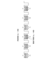
図21は、実施の形態5にかかる回転電機全体の俯瞰図である。図21が示すとおり、実施の形態5にかかる回転電機全体は、実施の形態1の固定子1の構成と同様に、電機子巻線のA相、B相、およびC相が界磁巻線Fを間に挟む形で構成されている。 FIG. 21 is a bird's-eye view of the entire rotating electric machine according to the fifth embodiment. As shown in FIG. 21, in the entire rotating electrical machine according to the fifth embodiment, similarly to the configuration of the stator 1 of the first embodiment, the A phase, B phase, and C phase of the armature winding are connected to the field winding. It is constructed with F in between.
図22は、実施の形態5にかかる回転子2の俯瞰図である。図22が示すとおり、実施の形態5にかかる回転電機全体は、回転子2が凸部回転子ユニット28と永久磁石回転子ユニット29とを有し、凸部回転子ユニット28と永久磁石回転子ユニット29とが軸方向に並んで組まれている。
FIG. 22 is an overhead view of the
永久磁石回転子ユニット29は、永久磁石4によって極が構成されている。永久磁石4は、実施の形態2の構成で示したように、コア18に埋め込まれていてもよい。
The permanent
一方、凸部回転子ユニット28は回転子コアの凸部16のみで構成されており、図22で示す例において凸部16の数は永久磁石4の数の半分である。
On the other hand, the
実施の形態5にかかる回転電機100も、Pa+Pf=Prを満たすように構成されている。実施の形態5にかかる回転電機100は上記の構成を備えるため、回転位置に応じて変わるインダクタンスの差分によって発生するリラクタンストルクによりトルクを得ることができる。The rotating
本開示技術はEVをはじめとする駆動用モータに応用でき、産業上の利用可能性を有する。 The disclosed technology can be applied to drive motors such as EVs, and has industrial applicability.
1 固定子、 2 回転子、 3 回転子鉄心、 4 永久磁石、 5 シャフト、 6 軸受、 7 固定子鉄心、 8 コイル、 9 固定子ブラケット、 10 カバー、 11 コアバック、 12 ティース、 13 スロット、 16 凸部、 18 コア、 19 凸部空隙長、 20 永久磁石部空隙長、 21 永久磁石部角度、 22 凸部角度、 28 凸部回転子ユニット、 29 永久磁石回転子ユニット、 100 回転電機、 F 界磁巻線。 1 stator, 2 rotor, 3 rotor core, 4 permanent magnet, 5 shaft, 6 bearing, 7 stator core, 8 coil, 9 stator bracket, 10 cover, 11 core back, 12 teeth, 13 slot, 16 convex part, 18 core, 19 convex gap length, 20 permanent magnet part gap length, 21 permanent magnet part angle, 22 convex part angle, 28 convex part rotor unit, 29 permanent magnet rotor unit, 100 rotating electric machine, F field magnetic winding.
Claims (6)
前記回転子は、回転軸の周方向に並ぶ複数の永久磁石と、前記周方向に並ぶ複数の凸部と、を有し、
前記固定子は、複数のティースと、前記複数のティースに巻線される電機子巻線と、前記複数のティースに巻線される界磁巻線と、を有し、
前記界磁巻線への通電と前記複数の永久磁石とによって前記複数の凸部に界磁極を形成し、
前記複数の永久磁石と前記複数のティースとが前記周方向に交互に間隔を空けて配置され、前記界磁極を形成し、
前記複数の永久磁石はすべて極性が同一であり、
前記電機子巻線の極対数Paと、前記界磁巻線の極対数Pfと、前記複数の永久磁石および前記複数の凸部で構成された前記界磁極の極数Prとが、|Pa-Pf|≠1、|Pr-Pf|≠1、および|Pa-Pr|≠1のいずれをも満たし、Prは偶数であることを特徴とする回転電機。A rotating electric machine including a stator and a rotor,
The rotor includes a plurality of permanent magnets arranged in the circumferential direction of the rotating shaft, and a plurality of convex parts arranged in the circumferential direction,
The stator includes a plurality of teeth, an armature winding wound around the plurality of teeth, and a field winding wound around the plurality of teeth,
forming field poles on the plurality of convex portions by energizing the field winding and the plurality of permanent magnets;
The plurality of permanent magnets and the plurality of teeth are arranged alternately at intervals in the circumferential direction to form the field pole,
All of the plurality of permanent magnets have the same polarity,
The number P a of pole pairs of the armature winding, the number P f of pole pairs of the field winding, and the number P r of the field poles constituted by the plurality of permanent magnets and the plurality of convex portions, A rotating electric machine that satisfies all of |P a −P f |≠1, |P r −P f |≠1, and |P a −P r |≠1, and P r is an even number.
前記回転子が凸部回転子ユニットと永久磁石回転子ユニットとを有し、
前記凸部回転子ユニットと前記永久磁石回転子ユニットとが、軸方向に並んで組まれていることを特徴とする回転電機。The rotating electric machine according to claim 1,
The rotor has a convex rotor unit and a permanent magnet rotor unit,
A rotating electric machine characterized in that the convex rotor unit and the permanent magnet rotor unit are assembled side by side in the axial direction.
Applications Claiming Priority (1)
| Application Number | Priority Date | Filing Date | Title |
|---|---|---|---|
| PCT/JP2021/001392 WO2022153517A1 (en) | 2021-01-18 | 2021-01-18 | Rotating electric machine |
Publications (3)
| Publication Number | Publication Date |
|---|---|
| JPWO2022153517A1 JPWO2022153517A1 (en) | 2022-07-21 |
| JPWO2022153517A5 JPWO2022153517A5 (en) | 2023-04-26 |
| JP7387034B2 true JP7387034B2 (en) | 2023-11-27 |
Family
ID=82448263
Family Applications (1)
| Application Number | Title | Priority Date | Filing Date |
|---|---|---|---|
| JP2022575022A Active JP7387034B2 (en) | 2021-01-18 | 2021-01-18 | rotating electric machine |
Country Status (5)
| Country | Link |
|---|---|
| US (1) | US20240055920A1 (en) |
| JP (1) | JP7387034B2 (en) |
| CN (1) | CN116746039A (en) |
| DE (1) | DE112021006828T5 (en) |
| WO (1) | WO2022153517A1 (en) |
Citations (2)
| Publication number | Priority date | Publication date | Assignee | Title |
|---|---|---|---|---|
| JP2017135863A (en) | 2016-01-28 | 2017-08-03 | 三菱電機株式会社 | Hybrid field type double gap synchronous machine |
| JP2019149891A (en) | 2018-02-27 | 2019-09-05 | 三菱電機株式会社 | Hybrid magnetic field type double gap synchronous machine |
Family Cites Families (1)
| Publication number | Priority date | Publication date | Assignee | Title |
|---|---|---|---|---|
| JP6823318B2 (en) | 2017-03-31 | 2021-02-03 | ダイキン工業株式会社 | Rotating electromechanical equipment |
-
2021
- 2021-01-18 US US18/266,812 patent/US20240055920A1/en active Pending
- 2021-01-18 DE DE112021006828.8T patent/DE112021006828T5/en active Pending
- 2021-01-18 CN CN202180089314.1A patent/CN116746039A/en active Pending
- 2021-01-18 WO PCT/JP2021/001392 patent/WO2022153517A1/en active Application Filing
- 2021-01-18 JP JP2022575022A patent/JP7387034B2/en active Active
Patent Citations (2)
| Publication number | Priority date | Publication date | Assignee | Title |
|---|---|---|---|---|
| JP2017135863A (en) | 2016-01-28 | 2017-08-03 | 三菱電機株式会社 | Hybrid field type double gap synchronous machine |
| JP2019149891A (en) | 2018-02-27 | 2019-09-05 | 三菱電機株式会社 | Hybrid magnetic field type double gap synchronous machine |
Also Published As
| Publication number | Publication date |
|---|---|
| US20240055920A1 (en) | 2024-02-15 |
| JPWO2022153517A1 (en) | 2022-07-21 |
| DE112021006828T5 (en) | 2023-11-02 |
| CN116746039A (en) | 2023-09-12 |
| WO2022153517A1 (en) | 2022-07-21 |
Similar Documents
| Publication | Publication Date | Title |
|---|---|---|
| JP4723118B2 (en) | Rotating electric machine and pulley drive device using the rotating electric machine | |
| JP4722309B2 (en) | Rotating electric machine and pulley drive device using the rotating electric machine | |
| WO2013047076A1 (en) | Rotating electric machine | |
| JPH0823664A (en) | Motor | |
| JP6048191B2 (en) | Multi-gap rotating electric machine | |
| JP6668844B2 (en) | Rotating electric machine | |
| JP7159800B2 (en) | Rotating electric machine | |
| JP6561692B2 (en) | Rotating electric machine | |
| JPWO2021131071A1 (en) | Hybrid field double gap synchronizer and drive system | |
| JP6760014B2 (en) | Rotating electric machine | |
| JP7387034B2 (en) | rotating electric machine | |
| JP2018148632A (en) | Rotary electric machine | |
| JP6895909B2 (en) | Hybrid field double gap synchronous machine | |
| WO2018221449A1 (en) | Electric motor | |
| JP6854875B1 (en) | Rotating machine | |
| JP2015162983A (en) | switched reluctance motor | |
| US20120112598A1 (en) | Electrical machine stator assembly | |
| JP2017063594A (en) | Brushless motor | |
| JP6877944B2 (en) | Synchronous reluctance type rotary electric machine | |
| JP6645352B2 (en) | Rotating electric machine | |
| JP2018170903A (en) | Stator of rotary electric machine | |
| JP2019140789A (en) | Rotary electric machine | |
| WO2019009195A1 (en) | Consequent motor | |
| WO2021182088A1 (en) | Permanent magnet synchronous motor | |
| US20230120571A1 (en) | Rotary electric machine |
Legal Events
| Date | Code | Title | Description |
|---|---|---|---|
| A621 | Written request for application examination |
Free format text: JAPANESE INTERMEDIATE CODE: A621 Effective date: 20221214 |
|
| A521 | Request for written amendment filed |
Free format text: JAPANESE INTERMEDIATE CODE: A523 Effective date: 20230320 |
|
| TRDD | Decision of grant or rejection written | ||
| A01 | Written decision to grant a patent or to grant a registration (utility model) |
Free format text: JAPANESE INTERMEDIATE CODE: A01 Effective date: 20231017 |
|
| A61 | First payment of annual fees (during grant procedure) |
Free format text: JAPANESE INTERMEDIATE CODE: A61 Effective date: 20231114 |
|
| R150 | Certificate of patent or registration of utility model |
Ref document number: 7387034 Country of ref document: JP Free format text: JAPANESE INTERMEDIATE CODE: R150 |