JP7382554B2 - Laser processing equipment and laser processing method using the same - Google Patents
Laser processing equipment and laser processing method using the same Download PDFInfo
- Publication number
- JP7382554B2 JP7382554B2 JP2021522718A JP2021522718A JP7382554B2 JP 7382554 B2 JP7382554 B2 JP 7382554B2 JP 2021522718 A JP2021522718 A JP 2021522718A JP 2021522718 A JP2021522718 A JP 2021522718A JP 7382554 B2 JP7382554 B2 JP 7382554B2
- Authority
- JP
- Japan
- Prior art keywords
- laser
- laser beam
- laser processing
- processing apparatus
- optical
- Prior art date
- Legal status (The legal status is an assumption and is not a legal conclusion. Google has not performed a legal analysis and makes no representation as to the accuracy of the status listed.)
- Active
Links
- 238000003672 processing method Methods 0.000 title claims description 17
- 230000003287 optical effect Effects 0.000 claims description 127
- 238000009826 distribution Methods 0.000 claims description 55
- 238000005253 cladding Methods 0.000 claims description 53
- 239000013307 optical fiber Substances 0.000 claims description 51
- 230000010355 oscillation Effects 0.000 claims description 33
- 239000000463 material Substances 0.000 claims description 15
- 230000035515 penetration Effects 0.000 claims description 11
- 230000002093 peripheral effect Effects 0.000 claims description 10
- 230000001678 irradiating effect Effects 0.000 claims description 8
- 239000000835 fiber Substances 0.000 claims description 7
- 239000004065 semiconductor Substances 0.000 claims description 4
- 238000003466 welding Methods 0.000 description 47
- 229910052751 metal Inorganic materials 0.000 description 13
- 239000002184 metal Substances 0.000 description 13
- 238000010586 diagram Methods 0.000 description 12
- 238000000034 method Methods 0.000 description 10
- 239000011324 bead Substances 0.000 description 5
- 230000015572 biosynthetic process Effects 0.000 description 5
- 230000031700 light absorption Effects 0.000 description 3
- 239000010453 quartz Substances 0.000 description 3
- VYPSYNLAJGMNEJ-UHFFFAOYSA-N silicon dioxide Inorganic materials O=[Si]=O VYPSYNLAJGMNEJ-UHFFFAOYSA-N 0.000 description 3
- 238000010521 absorption reaction Methods 0.000 description 2
- JNDMLEXHDPKVFC-UHFFFAOYSA-N aluminum;oxygen(2-);yttrium(3+) Chemical compound [O-2].[O-2].[O-2].[Al+3].[Y+3] JNDMLEXHDPKVFC-UHFFFAOYSA-N 0.000 description 2
- 230000002902 bimodal effect Effects 0.000 description 2
- 230000000694 effects Effects 0.000 description 2
- 238000002474 experimental method Methods 0.000 description 2
- 239000010410 layer Substances 0.000 description 2
- 150000002739 metals Chemical class 0.000 description 2
- 230000004048 modification Effects 0.000 description 2
- 238000012986 modification Methods 0.000 description 2
- 230000005855 radiation Effects 0.000 description 2
- 230000004043 responsiveness Effects 0.000 description 2
- 238000003860 storage Methods 0.000 description 2
- 239000000126 substance Substances 0.000 description 2
- 229910019901 yttrium aluminum garnet Inorganic materials 0.000 description 2
- 239000006117 anti-reflective coating Substances 0.000 description 1
- 239000010953 base metal Substances 0.000 description 1
- 238000006243 chemical reaction Methods 0.000 description 1
- 239000011248 coating agent Substances 0.000 description 1
- 238000000576 coating method Methods 0.000 description 1
- 239000000470 constituent Substances 0.000 description 1
- 230000007423 decrease Effects 0.000 description 1
- 230000003247 decreasing effect Effects 0.000 description 1
- 238000005553 drilling Methods 0.000 description 1
- 238000005516 engineering process Methods 0.000 description 1
- 230000002349 favourable effect Effects 0.000 description 1
- 239000011521 glass Substances 0.000 description 1
- 238000003698 laser cutting Methods 0.000 description 1
- 238000004519 manufacturing process Methods 0.000 description 1
- 239000000155 melt Substances 0.000 description 1
- 238000002844 melting Methods 0.000 description 1
- 230000008018 melting Effects 0.000 description 1
- 230000001681 protective effect Effects 0.000 description 1
- 239000011241 protective layer Substances 0.000 description 1
- 239000011347 resin Substances 0.000 description 1
- 229920005989 resin Polymers 0.000 description 1
Images


Classifications
-
- B—PERFORMING OPERATIONS; TRANSPORTING
- B23—MACHINE TOOLS; METAL-WORKING NOT OTHERWISE PROVIDED FOR
- B23K—SOLDERING OR UNSOLDERING; WELDING; CLADDING OR PLATING BY SOLDERING OR WELDING; CUTTING BY APPLYING HEAT LOCALLY, e.g. FLAME CUTTING; WORKING BY LASER BEAM
- B23K26/00—Working by laser beam, e.g. welding, cutting or boring
- B23K26/36—Removing material
- B23K26/38—Removing material by boring or cutting
- B23K26/382—Removing material by boring or cutting by boring
- B23K26/384—Removing material by boring or cutting by boring of specially shaped holes
-
- B—PERFORMING OPERATIONS; TRANSPORTING
- B23—MACHINE TOOLS; METAL-WORKING NOT OTHERWISE PROVIDED FOR
- B23K—SOLDERING OR UNSOLDERING; WELDING; CLADDING OR PLATING BY SOLDERING OR WELDING; CUTTING BY APPLYING HEAT LOCALLY, e.g. FLAME CUTTING; WORKING BY LASER BEAM
- B23K26/00—Working by laser beam, e.g. welding, cutting or boring
- B23K26/02—Positioning or observing the workpiece, e.g. with respect to the point of impact; Aligning, aiming or focusing the laser beam
- B23K26/06—Shaping the laser beam, e.g. by masks or multi-focusing
- B23K26/0604—Shaping the laser beam, e.g. by masks or multi-focusing by a combination of beams
- B23K26/0613—Shaping the laser beam, e.g. by masks or multi-focusing by a combination of beams having a common axis
-
- B—PERFORMING OPERATIONS; TRANSPORTING
- B23—MACHINE TOOLS; METAL-WORKING NOT OTHERWISE PROVIDED FOR
- B23K—SOLDERING OR UNSOLDERING; WELDING; CLADDING OR PLATING BY SOLDERING OR WELDING; CUTTING BY APPLYING HEAT LOCALLY, e.g. FLAME CUTTING; WORKING BY LASER BEAM
- B23K26/00—Working by laser beam, e.g. welding, cutting or boring
- B23K26/02—Positioning or observing the workpiece, e.g. with respect to the point of impact; Aligning, aiming or focusing the laser beam
- B23K26/035—Aligning the laser beam
-
- B—PERFORMING OPERATIONS; TRANSPORTING
- B23—MACHINE TOOLS; METAL-WORKING NOT OTHERWISE PROVIDED FOR
- B23K—SOLDERING OR UNSOLDERING; WELDING; CLADDING OR PLATING BY SOLDERING OR WELDING; CUTTING BY APPLYING HEAT LOCALLY, e.g. FLAME CUTTING; WORKING BY LASER BEAM
- B23K26/00—Working by laser beam, e.g. welding, cutting or boring
- B23K26/02—Positioning or observing the workpiece, e.g. with respect to the point of impact; Aligning, aiming or focusing the laser beam
- B23K26/06—Shaping the laser beam, e.g. by masks or multi-focusing
- B23K26/062—Shaping the laser beam, e.g. by masks or multi-focusing by direct control of the laser beam
-
- B—PERFORMING OPERATIONS; TRANSPORTING
- B23—MACHINE TOOLS; METAL-WORKING NOT OTHERWISE PROVIDED FOR
- B23K—SOLDERING OR UNSOLDERING; WELDING; CLADDING OR PLATING BY SOLDERING OR WELDING; CUTTING BY APPLYING HEAT LOCALLY, e.g. FLAME CUTTING; WORKING BY LASER BEAM
- B23K26/00—Working by laser beam, e.g. welding, cutting or boring
- B23K26/02—Positioning or observing the workpiece, e.g. with respect to the point of impact; Aligning, aiming or focusing the laser beam
- B23K26/06—Shaping the laser beam, e.g. by masks or multi-focusing
- B23K26/064—Shaping the laser beam, e.g. by masks or multi-focusing by means of optical elements, e.g. lenses, mirrors or prisms
-
- B—PERFORMING OPERATIONS; TRANSPORTING
- B23—MACHINE TOOLS; METAL-WORKING NOT OTHERWISE PROVIDED FOR
- B23K—SOLDERING OR UNSOLDERING; WELDING; CLADDING OR PLATING BY SOLDERING OR WELDING; CUTTING BY APPLYING HEAT LOCALLY, e.g. FLAME CUTTING; WORKING BY LASER BEAM
- B23K26/00—Working by laser beam, e.g. welding, cutting or boring
- B23K26/02—Positioning or observing the workpiece, e.g. with respect to the point of impact; Aligning, aiming or focusing the laser beam
- B23K26/06—Shaping the laser beam, e.g. by masks or multi-focusing
- B23K26/073—Shaping the laser spot
-
- B—PERFORMING OPERATIONS; TRANSPORTING
- B23—MACHINE TOOLS; METAL-WORKING NOT OTHERWISE PROVIDED FOR
- B23K—SOLDERING OR UNSOLDERING; WELDING; CLADDING OR PLATING BY SOLDERING OR WELDING; CUTTING BY APPLYING HEAT LOCALLY, e.g. FLAME CUTTING; WORKING BY LASER BEAM
- B23K26/00—Working by laser beam, e.g. welding, cutting or boring
- B23K26/20—Bonding
- B23K26/21—Bonding by welding
-
- B—PERFORMING OPERATIONS; TRANSPORTING
- B23—MACHINE TOOLS; METAL-WORKING NOT OTHERWISE PROVIDED FOR
- B23K—SOLDERING OR UNSOLDERING; WELDING; CLADDING OR PLATING BY SOLDERING OR WELDING; CUTTING BY APPLYING HEAT LOCALLY, e.g. FLAME CUTTING; WORKING BY LASER BEAM
- B23K26/00—Working by laser beam, e.g. welding, cutting or boring
- B23K26/36—Removing material
- B23K26/38—Removing material by boring or cutting
-
- H—ELECTRICITY
- H01—ELECTRIC ELEMENTS
- H01S—DEVICES USING THE PROCESS OF LIGHT AMPLIFICATION BY STIMULATED EMISSION OF RADIATION [LASER] TO AMPLIFY OR GENERATE LIGHT; DEVICES USING STIMULATED EMISSION OF ELECTROMAGNETIC RADIATION IN WAVE RANGES OTHER THAN OPTICAL
- H01S3/00—Lasers, i.e. devices using stimulated emission of electromagnetic radiation in the infrared, visible or ultraviolet wave range
- H01S3/005—Optical devices external to the laser cavity, specially adapted for lasers, e.g. for homogenisation of the beam or for manipulating laser pulses, e.g. pulse shaping
- H01S3/0071—Beam steering, e.g. whereby a mirror outside the cavity is present to change the beam direction
-
- H—ELECTRICITY
- H01—ELECTRIC ELEMENTS
- H01S—DEVICES USING THE PROCESS OF LIGHT AMPLIFICATION BY STIMULATED EMISSION OF RADIATION [LASER] TO AMPLIFY OR GENERATE LIGHT; DEVICES USING STIMULATED EMISSION OF ELECTROMAGNETIC RADIATION IN WAVE RANGES OTHER THAN OPTICAL
- H01S3/00—Lasers, i.e. devices using stimulated emission of electromagnetic radiation in the infrared, visible or ultraviolet wave range
- H01S3/23—Arrangements of two or more lasers not provided for in groups H01S3/02 - H01S3/22, e.g. tandem arrangements of separate active media
- H01S3/2383—Parallel arrangements
- H01S3/2391—Parallel arrangements emitting at different wavelengths
Description
本発明はレーザ加工装置及びそれを用いたレーザ加工方法に関する。 The present invention relates to a laser processing device and a laser processing method using the same.
従来、複数のレーザダイオードあるいはレーザダイオードバーから出射されるレーザ光をビーム結合して大出力のレーザ光を生成する技術が知られている。このようなレーザ光は、光ファイバによって伝送されワークをレーザ加工するのに用いられる。 2. Description of the Related Art Conventionally, a technique is known in which laser beams emitted from a plurality of laser diodes or laser diode bars are beam-combined to generate a high-output laser beam. Such laser light is transmitted through an optical fiber and used to laser-process a workpiece.
一方、ワークの材質や形状に応じて、レーザ光のビーム品質を変化させてレーザ加工を行う技術が近年、提案されてきている。 On the other hand, in recent years, techniques have been proposed in which laser processing is performed by changing the beam quality of laser light depending on the material and shape of the workpiece.
例えば、特許文献1は、レーザ光と光学的に結合可能な束状の複数の光ファイバにレーザ光を入射するレーザシステムを開示している。このレーザシステムは、レーザ光の光路上に配置されたリフレクタ又は集光レンズと、それらを動かすピエゾアクチュエータとを含む。ピエゾアクチュエータは、束状の複数の光ファイバにおけるレーザ光の入射位置を変化させることで、複数の光ファイバのうち、選択された光ファイバにレーザ光を入射させる。また、各光ファイバはマルチクラッドファイバからなる。ピエゾアクチュエータは、光ファイバにおけるレーザ光の入射位置を調整することでレーザ光のビームプロファイルを変化させている。
For example,
また、特許文献2には、集光レンズの位置を移動させたり、レーザ光の光路上にくさび状の光学素子を挿入したりすることで、マルチクラッドファイバの入射端面におけるレーザ光の入射位置を変化させる構成が提案されている。
Furthermore,
ところで、一般に、金属の光吸収率は波長依存性を有している。金属に照射される光の波長が短くなる程、金属の光吸収率は高くなる傾向にある。このような特性を利用して、互いに波長の異なるレーザ光を含む合波レーザ光によりレーザ加工を行うことが提案されている。しかし、特許文献1及び特許文献2には、このような技術は開示されていない。
By the way, in general, the light absorption rate of metals has wavelength dependence. The shorter the wavelength of light irradiated onto a metal, the higher the light absorption rate of the metal tends to be. Taking advantage of such characteristics, it has been proposed to perform laser processing using a combined laser beam containing laser beams with different wavelengths. However, such technology is not disclosed in
また、特許文献1に開示されたレーザシステムでは、比較的大型の光学部品であるリフレクタや集光レンズをアクチュエータで動かすため、その応答性に問題があり、レーザ光の光路を高速に変更し、光ファイバへの入射位置を変化させることが難しかった。このため、ワークの形状が変化した場合等に、当該変化に応じてレーザ光のパワー分布を制御するのが難しく、ワークの加工品質を維持するのが難しかった。
In addition, in the laser system disclosed in
また、特許文献2は、集光レンズの位置を移動させてレーザ光の入射位置を変化させる方法を開示している。この方法は、集光レンズを直線上にアクチュエータで動かす必要があるため、位置精度と応答性を両立させる上で問題があった。また、連続発振中のレーザ光の光路上に光学素子を挿入しながらこれを動かすと、レーザ光が光学素子のエッジ部分によって思わぬ方向に散乱されるため、レーザ加工に不具合を生じるおそれがあった。また、散乱されたレーザ光によってレーザ共振器の内部が損傷するおそれがあった。
Further,
本発明はかかる点に鑑みてなされたもので、その目的は、互いに波長の異なるレーザ光を合波するとともに、合波されたレーザ光のパワー分布を制御可能なレーザ加工装置及びそれを用いたレーザ加工方法を提供することにある。 The present invention has been made in view of the above, and an object of the present invention is to provide a laser processing device capable of combining laser beams having different wavelengths and controlling the power distribution of the combined laser beams, and a laser processing device using the same. An object of the present invention is to provide a laser processing method.
上記の目的を達成するため、本発明に係るレーザ加工装置は、レーザ光を発生させるレーザ発振器と、コアと、前記コアの外周側に前記コアと同軸に設けられた第1クラッドと、前記第1クラッドの外周側に前記コアと同軸に設けられた第2クラッドと、を少なくとも有し、入射端面および前記入射端面とは反対の出射端を有する光ファイバと、前記レーザ発振器に設けられ、前記レーザ光を前記光ファイバの入射端面に導入するビーム制御機構と、前記光ファイバの出射端に取付けられ、前記レーザ光をワークに向けて照射するレーザ光出射ヘッドと、を少なくとも備え、前記レーザ発振器は、第1波長の第1レーザ光を発生させる第1レーザ発振部と、前記第1波長と異なる第2波長の第2レーザ光を発生させる第2レーザ発振部と、を有し、前記ビーム制御機構は、前記第1レーザ光を受け取って所定の倍率で集光する第1集光レンズと、前記第2レーザ光を受け取って所定の倍率で集光する第2集光レンズと、前記第1集光レンズで集光された前記第1レーザ光と前記第2集光レンズで集光された前記第2レーザ光とを受け、前記第1レーザ光の光軸が前記第2レーザ光の光軸に一致するように前記第1レーザ光と前記第2レーザ光とを合波して前記レーザ光を形成し、前記レーザ光を前記光ファイバの入射端面に向かわせる光合波部材と、前記第1集光レンズと前記光合波部材との間の前記第1レーザ光の光路上及び前記第2集光レンズと前記光合波部材との間の前記第2レーザ光の光路上の少なくとも一方に配置され、前記第1レーザ光の光路及び前記第2レーザ光の光路のうち前記少なくとも一方の変更と保持をする光路変更保持機構と、前記光路変更保持機構の動作を制御するコントローラと、を少なくとも有し、前記ビーム制御機構は、前記光ファイバの入射端面における前記第1レーザ光及び前記第2レーザ光の少なくとも一方の入射位置を変化させることで、前記レーザ光出射ヘッドから出射される前記レーザ光のパワー分布を制御することを特徴とする。 In order to achieve the above object, a laser processing apparatus according to the present invention includes a laser oscillator that generates a laser beam, a core, a first cladding provided coaxially with the core on the outer peripheral side of the core, a second cladding provided coaxially with the core on the outer peripheral side of the first cladding, an optical fiber having an input end face and an output end opposite to the input end face; The laser oscillator includes at least a beam control mechanism that introduces a laser beam into an incident end face of the optical fiber, and a laser beam output head that is attached to an output end of the optical fiber and irradiates the laser beam toward a workpiece. has a first laser oscillation section that generates a first laser beam of a first wavelength, and a second laser oscillation section that generates a second laser beam of a second wavelength different from the first wavelength, and the beam The control mechanism includes: a first condenser lens that receives the first laser beam and condenses it at a predetermined magnification; a second condenser lens that receives the second laser beam and condenses it at a predetermined magnification; The first laser beam condensed by a first condenser lens and the second laser beam condensed by a second condenser lens are received, and the optical axis of the first laser beam is aligned with the second laser beam. an optical multiplexing member that combines the first laser beam and the second laser beam to form the laser beam so as to coincide with the optical axis, and directs the laser beam toward the input end surface of the optical fiber; On at least one of the optical path of the first laser beam between the first condensing lens and the optical multiplexing member and the optical path of the second laser beam between the second condensing lens and the optical multiplexing member. at least an optical path changing and holding mechanism arranged to change and maintain at least one of the optical path of the first laser beam and the optical path of the second laser beam, and a controller that controls the operation of the optical path changing and holding mechanism. The beam control mechanism controls the laser beam emitted from the laser beam emitting head by changing the incident position of at least one of the first laser beam and the second laser beam on the incident end surface of the optical fiber. It is characterized by controlling the power distribution of light.
この構成によれば、例えば、第2集光レンズと光合波部材との間の第2レーザ光の光路上に光路変更保持機構を設けることで、第2レーザ光の光路を容易に変更することができる。このことにより、第1レーザ光と第2レーザ光とから形成されたレーザ光のパワー分布を制御することができる。 According to this configuration, the optical path of the second laser beam can be easily changed by, for example, providing an optical path change holding mechanism on the optical path of the second laser beam between the second condensing lens and the optical multiplexing member. I can do it. Thereby, the power distribution of the laser beam formed from the first laser beam and the second laser beam can be controlled.
本発明に係るレーザ加工方法は、前記レーザ加工装置を用いたレーザ加工方法であって、前記ワークに向けて第1のパワー分布を有する前記レーザ光を照射する第1照射ステップと、引き続き、前記ワークに向けて前記第1のパワー分布とは異なる第2のパワー分布を有する前記レーザ光を照射する第2照射ステップと、を少なくとも備えたことを特徴とする。 The laser processing method according to the present invention is a laser processing method using the laser processing apparatus, and includes a first irradiation step of irradiating the workpiece with the laser beam having a first power distribution; The method is characterized by comprising at least a second irradiation step of irradiating the laser beam having a second power distribution different from the first power distribution toward the workpiece.
この方法によれば、溶接開始初期にワークに溶融池及びキーホールを確実に形成できるとともに、ワークの溶接品質を高められる。 According to this method, a molten pool and a keyhole can be reliably formed in the workpiece at the initial stage of welding, and the welding quality of the workpiece can be improved.
本発明のレーザ加工装置によれば、第1レーザ光と第2レーザ光とから形成されるレーザ光のパワー分布を制御することができる。本発明のレーザ加工方法によれば、ワークの溶接品質を高められる。 According to the laser processing apparatus of the present invention, it is possible to control the power distribution of the laser beam formed from the first laser beam and the second laser beam. According to the laser processing method of the present invention, the welding quality of a workpiece can be improved.
以下、本発明の実施形態を図面に基づいて詳細に説明する。以下の好ましい実施形態の説明は、本質的に例示に過ぎず、本発明、その適用物或いはその用途を制限することを意図するものでは全くない。 Hereinafter, embodiments of the present invention will be described in detail based on the drawings. The following description of preferred embodiments is merely exemplary in nature and is in no way intended to limit the invention, its applications, or its uses.
(実施形態1)
[レーザ加工装置の構成]
図1は、本実施形態に係るレーザ加工装置の構成の模式図を示し、レーザ加工装置1000は、レーザ発振器10とビーム制御機構20とコントローラ80と光ファイバ90とレーザ光出射ヘッド100とマニピュレータ110とを備えている。また、図2は、光ファイバ90における屈折率分布を示す。(Embodiment 1)
[Configuration of laser processing equipment]
FIG. 1 shows a schematic diagram of the configuration of a laser processing apparatus according to the present embodiment, and the
レーザ発振器10は、図示しない電源から電力の供給を受けてレーザ光LBを発生させるレーザ光源である。レーザ発振器10は、波長がλ1(以下、第1波長λ1と呼ぶことがある。)の第1レーザ光LB1を発生させる第1レーザ発振部11と、波長がλ2(以下、第2波長λ2と呼ぶことがある。)の第2レーザ光LB2を発生させる第2レーザ発振部12と、を有している。なお、第1波長λ1と第2波長λ2とは互いに異なる値であり、本実施形態では、第1波長λ1は、第2波長λ2よりも長い。
The
例えば、第1レーザ発振部11をファイバレーザかディスクレーザか、あるいやYAG(Yttrium Aluminum Garnet)レーザとし、第2レーザ発振部12を半導体レーザとすることもできる。この場合、第1波長λ1は、1000nm~1100nmの範囲に、第2波長λ2は、800nm~1000nmの範囲にそれぞれ設定される。なお、第2レーザ発振部12を可視光レーザとし、第2波長λ2を400nm~800nmの範囲に設定するようにしてもよい。
For example, the first
また、ワーク200の材質に応じて、第1レーザ発振部11及び第2レーザ発振部12を別の構成としてもよい。例えば、第1レーザ発振部11を半導体レーザとし、第2レーザ発振部12を可視光レーザとすることもできる。この場合、第1波長λ1は、800nm~1000nmの範囲に、第2波長λ2は、400nm~800nmの範囲にそれぞれ設定される。
Further, the first
また、第1レーザ発振部11及び第2レーザ発振部12はそれぞれ、単一のレーザ光源で構成されていてもよいし、複数のレーザモジュールで構成されていてもよい。後述するように、ビーム制御機構20で第1レーザ光LB1と第2レーザ光LB2とが合波されてレーザ光LBとして光ファイバ90に入射される。
Further, each of the first
ビーム制御機構20は、レーザ発振器10に設けられており、第1レーザ光LB1と第2レーザ光LB2とを合波し、合波されたレーザ光LBを光ファイバ90の入射端面に導入するとともに、光ファイバ90の出射端から出射されるレーザ光LBのパワー分布を制御する。ビーム制御機構20の構成及び動作については後で述べる。
The
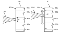
光ファイバ90は、いわゆるマルチクラッドファイバである。光ファイバ90は、コア90aと、コア90aの外周側にコア90aと同軸に設けられた第1クラッド90bと、第1クラッド90bの外周側にコア90aと同軸に設けられた第2クラッド90cとを有する。コア90aと第1クラッド90bと第2クラッド90cとはその主成分が石英からなり、図2に示すように、コア90aの屈折率が最も高く、第1クラッド90b、第2クラッド90cの順に屈折率が低くなる。第1クラッド90bと第2クラッド90cとの屈折率は、共に屈折率を下げることのできる、異なった種類または濃度の物質をドーピングすることによって調整されてもよい。また、コア90aの屈折率は、屈折率を上げることのできる、異なった種類または濃度の物質をドーピングすることによって調整されてもよい。このような屈折率分布を持った光ファイバ90では、所定の角度でコア90aに入射されたレーザ光LBは第1クラッド90bに入ることなく、コア90aの中を伝搬することができるが、所定の角度で第1クラッド90bに入射されたレーザ光LBは第2クラッド90cに入ることなく、第1クラッド90bの中を伝搬することができる。このようなレーザ光LBの伝搬方法を実現するための光ファイバの構造として、図2に示す構造はあくまでも一例であり、必ずしもコア90aと第1クラッド90bと第2クラッド90cとで異なった屈折率を持たせる必要はない。例えば、コア90aと第1クラッド90bと第2クラッド90cとを同じ屈折率N1にすると共に、コア90aと第1クラッド90bとの間に、また第1クラッド90bと第2クラッド90cとの間に、屈折率N2(N2<N1)を有する薄い層を設けてもよい。そうすることによって、所定の角度でコア90aに入射されたレーザ光LBは第1クラッド90bに入ることなく、コア90aの中を伝搬することができるが、所定の角度で第1クラッド90bに入射されたレーザ光LBは第2クラッド90cに入ることなく、第1クラッド90bの中を伝搬することができる。屈折率N2を有する層は、その主成分が石英であるが、屈折率を下げることのできる物質をドーピングすればよい。光ファイバ90に入射されたレーザ光LBは、コア90a及び/または第1クラッド90bを伝搬し、光ファイバ90の出射端に到達する。なお、図2に示すように、コア90aの直径をφ1とし、第1クラッド90bの直径をφ2とする。また、図示しないが、第2クラッド90cの外周面には光ファイバ90を機械的に保護する皮膜または樹脂系の保護層が設けられている。
The
レーザ光出射ヘッド100は、光ファイバ90の出射端に取付けられており、光ファイバ90で伝送されたレーザ光LBをワーク200に向けて照射し、ワーク200がレーザ加工される。なお、レーザ光出射ヘッド100の内部には図示しない光学部品、例えば、コリメータレンズや集光レンズや保護ガラス等が配設されている。
The laser
コントローラ80は、レーザ発振器10のレーザ発振を制御する。具体的には、レーザ発振器10に接続された図示しない電源に対して出力電流やオン時間等の制御信号を供給することにより、第1レーザ発振部11及び第2レーザ発振部12でのレーザ発振制御、例えば、第1レーザ光LB1及び第2レーザ光LB2の出力パワー制御やそのON/OFF制御を行う。
The
また、コントローラ80は、選択されたレーザ加工プログラムの内容に応じて、ビーム制御機構20に設けられたモータ70(図4A,4B参照)の駆動制御を行う。さらに、コントローラ80は、マニピュレータ110の動作を制御する。なお、レーザ加工プログラムは、図示しない記憶部に保存されている。記憶部はコントローラ80の内部に設けられていてもよいし、コントローラ80の外部に設けられ、コントローラ80とデータのやり取りを可能に構成されていてもよい。なお、コントローラ80はビーム制御機構20の一部を構成している。
Further, the
マニピュレータ110はコントローラ80に接続され、前述のレーザ加工プログラムに応じて所定の軌跡を描くようにレーザ光出射ヘッド100を移動させる。なお、マニピュレータ110の動作を制御するコントローラを別に設けるようにしてもよい。
The
[ビーム制御機構の構成]
図3は、ビーム制御機構をX方向から見た模式図を、図4Aは、ビーム制御機構の要部をY方向から見た模式図を、図4Bは、ビーム制御機構の要部をZ方向から見た模式図をそれぞれ示す。なお、本願明細書において、ダイクロイックミラー33から光ファイバ90に向かうレーザ光LBの進行方向をZ方向と、モータ70の出力軸70aの延びる方向をX方向と、X方向及びZ方向をそれぞれ直交する方向をY方向とそれぞれ呼ぶことがある。[Configuration of beam control mechanism]
Figure 3 is a schematic diagram of the beam control mechanism viewed from the X direction, Figure 4A is a schematic diagram of the main parts of the beam control mechanism viewed from the Y direction, and Figure 4B is a schematic diagram of the main parts of the beam control mechanism viewed from the Z direction. A schematic view of each is shown. In the present specification, the traveling direction of the laser beam LB from the
また、モータ70の出力軸70aの軸線をX軸(第1軸)と呼ぶことがある。図3に示すように、X軸はレーザ光LBと第1レーザ光LB1と第2レーザ光LB2の光軸にそれぞれ略直交している。
Further, the axis of the
なお、本願明細書において、「略直交」とは、各部品の組立公差を含んで直交しているという意味であり、厳密に直交していることまでを要求するものではない。同様に、「略等しい」とは、各部品の製造公差や組立公差を含んで等しいという意味であり、厳密に比較対象となる両者が等しいことまでを要求するものではない。また、「略等しい」とは、推定値との比較において所定の確度で等しいことも意味するが、厳密に推定値と比較対象とが等しいことまでを要求するものではない。 Note that in the present specification, "substantially orthogonal" means orthogonal to each other including the assembly tolerance of each component, and does not require that they be strictly orthogonal. Similarly, "substantially equal" means equal including manufacturing tolerances and assembly tolerances of each part, and does not strictly require that the two objects to be compared be equal. Furthermore, "substantially equal" means that the estimated value and the comparison target are equal with a predetermined accuracy, but it does not strictly require that the estimated value and the comparison target be equal.
図3及び図4A,4Bに示すように、ビーム制御機構20は、第1集光レンズ31及び第2集光レンズ32と光学部材50とダイクロイックミラー(光合波部材)33とモータ70とコントローラ80とを有している。後で述べるように、モータ70と光学部材50とは、第2集光レンズ32で集光された後の第2レーザ光LB2の光路の変更と保持をする光路変更保持機構40として機能する。
As shown in FIGS. 3, 4A, and 4B, the
第1及び第2レーザ光LB1,LB2は、それぞれ第1レーザ発振部11と第2レーザ発振部12とから発生したレーザ光であり、図示しない光学部品、例えば、コリメートレンズ等により平行光に変換された状態で第1及び第2集光レンズ31,32にそれぞれ入射される。第1及び第2集光レンズ31,32は、図示しないコリメートレンズに対して所定の倍率で第1及び第2レーザ光LB1,LB2をそれぞれ集光する。
The first and second laser beams LB1 and LB2 are laser beams generated from the first
ダイクロイックミラー33は、第1集光レンズ31で集光された後の第1レーザ光LB1の光路と第2集光レンズ32で集光された後の第2レーザ光LB2の光路とが交差する位置に配置されている。また、ダイクロイックミラー33に入射される前の第1レーザ光LB1の光軸と第2レーザ光LB2の光軸とは互いに直交しており、ダイクロイックミラー33の表面はX方向から見て第2レーザ光LB2の光軸と45度の角度をなすように配置されている。
In the
ダイクロイックミラー33は、第1レーザ光LB1をそのまま透過させる一方、99.0%以上、できれば100%に近い比率で第2レーザ光LB2を表面で反射する。モータ70の出力軸70aが初期位置にある場合、光学部材50は第2レーザ光LB2の光軸に対して略直交するように配置される。この状態では、第2レーザ光LB2は、その光軸が第1レーザ光LB1の光軸と重なるようになり、第1レーザ光LB1と第2レーザ光LB2とが合波される。合波された後のレーザ光LBが光ファイバ90に入射される。
The
光学部材50は、第1レーザ光LB1及び第2レーザ光LB2に対して透明な材質からなる平行平板状の部材である。光学部材50は、例えば、石英からなり、第1波長λ1及び第2波長λ2に対して1よりも大きい屈折率を有する。光学部材50は、入射したレーザ光、この場合は第2レーザ光LB2に対する反射率をできるだけ下げるために、両面に反射防止コーティイングを施されたものを使用してよい。反射防止コーティングを施した場合の光学部材50の反射率は、1%よりはるかに小さいことが望ましい。光学部材50は、第2集光レンズ32とダイクロイックミラー33との間の第2レーザ光LB2の光路上に配置されている。
The
モータ70は出力軸70aを有しており、ホルダ60を介して光学部材50に連結されている。モータ70を駆動させて出力軸70aがX軸周りに回転することで、光学部材50はホルダ60との連結部を中心としてYZ平面内に回転する。なお、モータ70は一方向(図3に示す方向A)のみに回転するのではなく、正逆両方向(図3に示す方向B)に回転可能に構成されている。また、回転周波数は可変であり、溶接加工を行う際には、数Hz~数kHz程度の範囲で変化させることができる。また、後述するように、ビーム制御機構20を動作させる場合、モータ70は一方向に連続して回転動作を行うのではなく、所定の角度範囲を回転する。言い換えると、光学部材50はホルダ60との連結部を中心として所定の角度で傾動する。また、モータ70は、光学部材50を設定された角度範囲で高速に往復回転させることができる。また、モータ70はコントローラ80に接続され、コントローラ80からの制御信号によって駆動される。
The
なお、光学部材50のZ方向の厚さは1mmから数mm程度であるが、特にこれに限定されず、光ファイバ90の入射端面90dにおける第2レーザ光LB2の移動距離とモータ70の回転角度との関係で適宜別の値に変更しうる。当該厚さが数mm程度であると、また、第2集光レンズ32とダイクロイックミラー33との間の、集光された第2レーザ光LB2が通過する狭い位置に設置するため、その必要サイズが小さく、モータ70によって高速、例えば、数kHzの回転周波数で往復回転させることが容易となる。
Note that the thickness of the
[レーザ光のパワー分布の変更手順]
次に、レーザ光LBのパワー分布の変更手順について説明する。[Procedure for changing the power distribution of laser light]
Next, a procedure for changing the power distribution of the laser beam LB will be explained.
図5は、第2レーザ光の入射位置が第1レーザ光の入射位置とは異なる場合の光ファイバの入射端近傍の状態を示す。図6は、図5に示す状態でレーザ光出射ヘッド100から出射されるレーザ光のビームプロファイルの一例を示す。なお、図6に示すビームプロファイルは、レーザ光出射ヘッド100から出射され、焦点位置に結像されたレーザ光LBのパワー分布に相当する。また、図6に示すビームプロファイルは、光ファイバ90の出射端から出射されたレーザ光LBのパワー分布に相当する。
FIG. 5 shows the state near the input end of the optical fiber when the input position of the second laser beam is different from the input position of the first laser beam. FIG. 6 shows an example of a beam profile of the laser light emitted from the laser
コントローラ80からの制御信号により、モータ70を図3に示す方向Aに所定の角度で回転させると、モータ70の回転に応じて光学部材50はホルダ60との連結部を中心としてYZ平面内を所定の角度で傾動する。この角度に応じて、光学部材50の光入射面と第2レーザ光LB2の光軸との角度が変化し、光学部材50の内部で第2レーザ光LB2の光路が変更される。光路が変更された第2レーザ光LB2がダイクロイックミラー33で反射されると、第2レーザ光LB2の光軸とダイクロイックミラー33を透過した後の第1レーザ光LB1の光軸とが近接するものの、所定の距離だけずれて、第1レーザ光LB1と第2レーザ光LB2とが合波される。その結果、例えば、図5に示すように、第1レーザ光LB1が光ファイバ90のコア90aに入射される一方、第2レーザ光LB2が光ファイバ90の第1クラッド90bに入射される。また、その場合のレーザ光LBのビームプロファイルは、図6に示すように、単峰状の部分とその両側に形成された半値幅の広いテラス状の部分とを含んでいる。前者がコア90a内に伝送される第1レーザ光LB1に対応し、後者が第1クラッド90b内に伝送される第2レーザ光LB2に対応する。言うまでもなく、図5の矢印で示したように、第2レーザ光LB2の全部またはその一部をコア90aの中に入るようモータ70を駆動して光学部材50を傾動させてもよい。
When the
このように、モータ70を駆動して光学部材50を傾動させることで、光ファイバ90の入射端面90dにおける第2レーザ光LB2の入射位置を連続的に変化させることができる。また、第2レーザ光LB2の入射位置を変化させることで、例えば、コア90aに伝送される第1レーザ光LB1と第1クラッド90bに伝送される第2レーザ光LB2のパワー比率を変化させることができる。
In this manner, by driving the
図7は、図5に示す状態で第1レーザ光と第2レーザ光とのパワー比率を変えた場合のレーザ光出射ヘッド100から出射されるレーザ光のビームプロファイルを示す。なお、第1レーザ光LB1のパワーと第2レーザ光LB2のパワーはそれぞれコントローラ80からの制御信号によって第1レーザ発振部11と第2レーザ発振部12とを制御して変更される。
FIG. 7 shows a beam profile of the laser beam emitted from the laser
第1レーザ光LB1のパワーをP1、第2レーザ光LB2のパワーをP2とそれぞれしたとき、P1が有限の値で、P2がゼロの場合、レーザ光LBのビームプロファイルは半値幅の狭い単峰状となる(図7のケース1)。
When the power of the first laser beam LB1 is P1 and the power of the second laser beam LB2 is P2, if P1 is a finite value and P2 is zero, the beam profile of the laser beam LB is a single peak with a narrow half width. (
一方、P1とP2との比率を以下の式(1)に示す関係とすると、ビームプロファイルは単峰状の部分とその両側に形成された半値幅の広いテラス状の部分とを含むように変化する(図7のケース2)。前者がコア90a内に伝送される第1レーザ光LB1に対応し、後者が第1クラッド90b内に伝送される第2レーザ光LB2に対応する。
On the other hand, if the ratio of P1 and P2 is set to the relationship shown in equation (1) below, the beam profile changes to include a single-peaked portion and terrace-like portions with a wide half-width formed on both sides of the unimodal portion. (
P1/P2>φ12/(φ22-φ12) ・・・(1)
P1とP2との比率を以下の式(2)に示す関係とすると、レーザ光LBのビームプロファイルのうち単峰状の部分のピーク値とテラス状の部分のピーク値が一致するようになり、レーザ光LBのビームプロファイルは単峰状となるものの、コア90a内にのみ第1レーザ光LB1が伝送される場合に比べて、そのピーク値は低く、かつ半値幅は大きくなる(図7のケース3)。P1/P2>φ1 2 /(φ2 2 -φ1 2 ) ...(1)
If the ratio of P1 and P2 is set to the relationship shown in equation (2) below, the peak value of the unimodal portion of the beam profile of the laser beam LB will match the peak value of the terraced portion, Although the beam profile of the laser beam LB is unimodal, its peak value is lower and the half-width is larger than in the case where the first laser beam LB1 is transmitted only into the
P1/P2=φ12/(φ22-φ12) ・・・(2)
P1とP2との比率を以下の式(3)に示す関係とすると、レーザ光LBのビームプロファイルのうち、コア90a内に伝送される成分に対応する部分のピーク値が低下し、第1クラッド90b内に伝送される成分に対応する部分のピーク値が高くなり、ビームプロファイルは双峰状となる(図7のケース4)。P1/P2=φ1 2 /(φ2 2 -φ1 2 ) ...(2)
If the ratio of P1 and P2 is set to the relationship shown in equation (3) below, the peak value of the portion of the beam profile of the laser beam LB that corresponds to the component transmitted into the core 90a decreases, and the The peak value of the portion corresponding to the component transmitted within 90b becomes high, and the beam profile becomes bimodal (
P1/P2<φ12/(φ22-φ12) ・・・(3)
さらに、P1がゼロで、P2が有限の値の場合、レーザ光LBのビームプロファイルは双峰状となり、かつ中心部でのパワーはゼロとなる(図7のケース5)。P1/P2<φ1 2 /(φ2 2 -φ1 2 ) ...(3)
Further, when P1 is zero and P2 is a finite value, the beam profile of the laser beam LB becomes bimodal, and the power at the center becomes zero (
以上の説明では、第1レーザ光LB1と第2レーザ光LB2のパワーを制御することで図7に示したビームプロファイルを得たが、両者のパワーを固定しても、第2レーザ光LB2の照射位置を変えることで図7に示した一部のビームプロファイルを得ることができる。例えば、第1レーザ光LB1と第2レーザ光LB2とのパワーが式(1)を満たすケース2について説明する。図7で既に説明したとおり、第2レーザ光LB2を第1クラッド90bに全部入れた場合に、ケース2のビームプロファイルが得られている。図5では図示していないが、第2レーザ光LB2の全部がコア90aに入射すると、図7のケース1と同じ形のビームプロファイルを得ることができる。ただし、このビームプロファイルには第1レーザ光LB1と第2レーザ光LB2の両方が含まれる。また、第2レーザ光LB2の照射位置をコア90aと第1クラッド90bとの境界をまたがるようにすると、第2レーザ光LB2の一部のパワーがコア90aにも入るので、図7のケース2において、第1レーザ光LB1に対応する部分のビームプロファイルの高さを制御することができる。ただし、当該部分には第1レーザ光LB1と第2レーザ光LB2の両方が含まれる。第1レーザ光LB1と第2レーザ光LB2とのパワーが式(2)または式(3)に満たすケース3,4についての説明を省略するが、第2レーザビームLB2の照射位置を制御することによっても図7に示すケース1~4のビームプロファイルを得ることができる。
In the above explanation, the beam profile shown in FIG. 7 was obtained by controlling the powers of the first laser beam LB1 and the second laser beam LB2, but even if the powers of both are fixed, the power of the second laser beam LB2 is By changing the irradiation position, some of the beam profiles shown in FIG. 7 can be obtained. For example, a
以上説明したように、光ファイバ90の入射端面90dにおいて、第1レーザ光LB1と第2レーザ光LB2の入射位置をそれぞれ異ならせ、もしくは、第1レーザ光LB1と第2レーザ光LB2のパワーを変化させることで、レーザ光出射ヘッド100から出射されるレーザ光LBのビームプロファイル、つまり、パワー分布を変化させることができる。
As explained above, on the
また、レーザ光出射ヘッド100から出射されるレーザ光LBのビームプロファイルを変化させることで、ワーク200の加工形状、例えば、溶接形状を良好なものとすることができる。このことについてさらに説明する。
Furthermore, by changing the beam profile of the laser beam LB emitted from the laser
図8は、ワークの溶接箇所の断面模式図であり、一般に、金属からなるワーク200をレーザ溶接する際、レーザ光LBが照射された部分が加熱されて溶け込みを生じ、溶融池210が形成される。また、レーザ光LBが照射された部分では溶融池210を構成する材料の蒸発が起こり、その反力で溶融池210の内部にキーホール220が形成される。
FIG. 8 is a schematic cross-sectional view of a welding location of a workpiece. Generally, when a
例えば、図6に示すビームプロファイルを有するレーザ光LBをレーザ光出射ヘッド100からワーク200に向けて照射した場合、ビームプロファイルの各部分に含まれる第1レーザ光LB1と第2レーザ光LB2の比率により、キーホール220の周囲では、次に示すようにレーザ光LBが吸収または反射される。
For example, when the laser beam LB having the beam profile shown in FIG. 6 is irradiated from the laser
まず、図8に示す経路Iを通るレーザ光LBの主成分は第1レーザ光LB1であり、第2レーザ光LB2が若干混合されている場合がある。経路Iを通るレーザ光LBは、キーホール220の内壁面で複数回反射されつつ、キーホール220の内部に進入し、溶融池210に吸収される。
First, the main component of the laser beam LB passing through the path I shown in FIG. 8 is the first laser beam LB1, and the second laser beam LB2 may be slightly mixed therein. The laser beam LB passing through the path I enters the inside of the
一方、経路IIを通るレーザ光LBの主成分は第2レーザ光LB2であり、第1レーザ光LB1が若干混合されている場合がある。経路IIを通るレーザ光LBは、一部がキーホール220の内壁面で反射されて溶融池210の外部に放射される。この放射分は、溶融池210及びキーホール220の形成に寄与しないため、損失となる。
On the other hand, the main component of the laser beam LB passing through the path II is the second laser beam LB2, and the first laser beam LB1 may be slightly mixed therein. A portion of the laser beam LB passing through the path II is reflected by the inner wall surface of the
また、経路IIIを通るレーザ光LBのほとんどは第2レーザ光LB2である。経路IIIを通るレーザ光は、一部が溶融池210の表面で反射されてワーク200の外部に放射される。この放射分は、溶融池210及びキーホール220の形成に寄与しないため、損失となる。
Furthermore, most of the laser beam LB passing through path III is the second laser beam LB2. A portion of the laser beam passing through path III is reflected by the surface of
以上説明したように、経路II及びIIIを通るレーザ光LBの一部はレーザ溶接に寄与しない損失分となりうる。一方、前述したように、金属の光吸収率は波長が短くなる程高くなる。従って、経路II及びIIIを通るレーザ光LB、言い換えると、第1クラッド90bに入射される第2レーザ光LB2の第2波長λ2を第1レーザ光LB1の第1波長λ1よりも短い値に設定することで、ワーク200の母材金属や溶融池210での第2レーザ光LB2の吸収率が高くなるため、レーザ光LBの全体の損失を減らすことができる。
As explained above, a portion of the laser beam LB passing through paths II and III may become a loss that does not contribute to laser welding. On the other hand, as described above, the light absorption rate of metal increases as the wavelength becomes shorter. Therefore, the second wavelength λ2 of the laser beam LB passing through paths II and III, in other words, the second laser beam LB2 incident on the
例えば、図7のケース1に示すようなビームプロファイルのレーザ光LBでワーク200をレーザ溶接すると、ワーク200の溶け込み量が多くなりキーホール220が深くなる一方、キーホール220の開口221があまり拡がらず、キーホール220の内部でくびれ部(図示せず)を生じてしまうことがある。また、くびれ部が閉じてしまうことにより溶融池210の内部に気泡(図示せず)が残存してしまう。さらに、一度閉じたキーホール220がレーザ光LBの照射を受けて再度キーホール220が形成される際には、表面に向かって溶融金属が急激に噴出すると、ワーク200の表面にスパッタ(図示せず)が付着したり、溶融池210の表面が波立ったりする。このような波が生じると、レーザ溶接の進行方向に沿って、溶融池210の後方でワーク200の表面に凹凸211(後方振動部211ともいう)が生じてしまう。この波は溶融池210が急速に冷却されて固化すると、溶接ビード表面に凹凸211として残ってしまう。
For example, when the
また、この波は溶融池210と凝固部分の端で反射して跳ね返ってくる。この反射波がキーホール220まで到達すると、キーホール220を埋めるように流れ込んでしまう。流れ込んだ溶融金属はレーザ光に急速加熱されて、金属蒸気を急に発生させるために、キーホール220の円柱状形状が乱れる。以上説明した、キーホール220の形状乱れや気泡やスパッタの発生や溶融池210の表面に生じる凹凸211は,溶接品質を低下させる要因となっていた。
Further, this wave is reflected and bounced back at the edges of the
一方、本実施形態によれば、ビーム制御機構20を用いてレーザ光出射ヘッド100からワーク200に向けて照射されるレーザ光LBのパワー分布、具体的には、コア90aから出射される第1レーザ光LB1と第1クラッド90bから出射される第2レーザ光LB2のパワー比を変化させることができる。例えば、光学部材50の傾動角度を調整して、図6に示すようなビームプロファイルのレーザ光LBをワーク200に向けて照射することができる。
On the other hand, according to the present embodiment, the power distribution of the laser beam LB irradiated from the laser
このような場合、溶け込み深さは若干浅くなるものの、コア90aから出射された第1レーザ光LB1により所望の溶け込み深さが得られる。一方、第1クラッド90bから出射された第2レーザ光LB2によりキーホール220の開口221を拡げることができる。また、第2レーザ光LB2がキーホール220付近のワーク200を加熱し、より大きめの溶融池210をキーホール220の周りに形成する。そのため、キーホール220付近における溶融金属の量が増え、キーホール220から噴出した金属蒸気に伴って発生したキーホール220の開口221付近の溶融池210の振動を小さくすることができる。さらに、第2レーザ光LB2の第2波長λ2は第1レーザ光LB1の第1波長λ1よりも短いため、キーホール220の開口221付近の内壁面や溶融池210の表面でより多くの第2レーザ光LB2が吸収される。このことにより、キーホール220の開口221付近の内壁面同士がくっついて、くびれ部が形成されるのを抑制でき、ひいては溶融池210の内部に気泡が発生するのを抑制できる。また、キーホール220の内部から表面に向かって急激に溶融金属が噴出するのを幾分抑えられ、溶融池210の後方で溶融池210の表面に形成される凹凸211を小さくできる。さらに、キーホール220の開口221付近の溶融池210の振動を小さくすることができ、キーホール220の形状乱れを抑制することにもつながる。以上のことから、レーザ溶接における溶接品質を高めることができる。
In such a case, although the penetration depth becomes slightly shallower, the desired penetration depth can be obtained by the first laser beam LB1 emitted from the
また、レーザ光出射ヘッド100から出射されるレーザ光LBのパワー分布をレーザ溶接中に切り替えることによって、溶接品質を高めることができる。
Further, by switching the power distribution of the laser beam LB emitted from the laser
図9は、ワークの溶接シーケンスを示し、溶接開始直後では、ワーク200に溶融池210は形成されていない。溶接開始直後では、所望の溶け込み深さを得ることが望まれる。そのために、コントローラ80は、モータ70を駆動して、コア90aに第1レーザ光LB1と第2レーザ光LB2の両方を入射させる。これにより、ワーク200に照射されるレーザ光LBのスポット径を小さくし、溶接箇所におけるレーザ光LBのパワー密度を高めると共に、波長の短い第2レーザ光LB2によってワーク200のレーザ吸収率を高めている(第1照射ステップ)。一方、溶融池210及びキーホール220が形成された後には、前述したようなくびれ部等の形成を抑制することが望まれる。そのために、コントローラ80は、モータ70を駆動して、第1クラッド90bに第2レーザ光LB2を入射させる。これにより、キーホール220の開口221が拡がるようにし、かつ所望の溶け込み深さが得られるようにする(第2照射ステップ)。また、このときに、必要に応じて、第1レーザ光LB1のパワーまたは第2レーザ光LB2のパワーを変化させてもよい。
FIG. 9 shows a workpiece welding sequence, and immediately after welding starts, a
このようにすることで、レーザ溶接において、ワーク200に確実に溶融池210及びキーホール220を形成できるとともに、ワーク200内部の気泡や表面の凹凸211等の発生を抑制して、溶接品質を高めることができる。
By doing so, in laser welding, the
また、これらに限られず、ワーク200の材質及び/またはワーク200におけるレーザ加工対象部位の形状に応じて、ビーム制御機構20を動作させて、レーザ光出射ヘッド100から出射されるレーザ光LBのパワー分布を制御することで、種々の材質や形状を有するワーク200をレーザ加工することができ、かつその加工品質を高められる。
In addition, the power of the laser beam LB emitted from the laser
[効果等]
以上説明したように、本実施形態に係るレーザ加工装置1000は、レーザ光LBを発生させるレーザ発振器10と、コア90aと、コア90aの外周側にコア90aと同軸に設けられた第1クラッド90bと、第1クラッド90bの外周側にコア90aと同軸に設けられた第2クラッド90cと、を少なくとも有し、入射端面90dおよび入射端面90dとは反対の出射端を有する光ファイバ90と、レーザ発振器10に設けられ、レーザ光を光ファイバ90の入射端面90dに導入するビーム制御機構20と、光ファイバ90の出射端に取付けられ、レーザ光LBをワーク200に向けて照射するレーザ光出射ヘッド100と、を少なくとも備えている。[Effects etc.]
As described above, the
レーザ発振器10は、第1波長λ1の第1レーザ光LB1を発生させる第1レーザ発振部11と、第1波長λ1と異なる第2波長λ2の第2レーザ光LB2を発生させる第2レーザ発振部12と、を有している。
The
ビーム制御機構20は、第1レーザ光LB1を受け取って所定の倍率で集光する第1集光レンズ31と、第2レーザ光LB2を受け取って所定の倍率で集光する第2集光レンズ32と、第1集光レンズ31で集光された第1レーザ光LB1と第2集光レンズ32で集光された第2レーザ光LB2とを受け、第1レーザ光LB1の光軸が第2レーザ光LB2の光軸に一致するように第1レーザ光LB1と第2レーザ光LB2とを合波してレーザ光LBを形成し、前記レーザ光を光ファイバ90の入射端面90dに向かわせるダイクロイックミラー(光合波部材)33と、を少なくとも有している。ここで、「一致」の用語は、第1レーザ光LB1の光軸が第2レーザ光LB2の光軸に重なること、および、第1レーザ光LB1の光軸が第2レーザ光LB2の光軸に所定の距離を保って近接すること、の両方を含む。
The
また、ビーム制御機構20は、第2集光レンズ32とダイクロイックミラー33との間の第2レーザ光LB2の光路上に配置され、第2レーザ光LB2の光路の変更と保持をする光路変更保持機構40と、光路変更保持機構40の動作を制御するコントローラ80と、を有している。本実施形態では、光路変更保持機構40は、平行平板状の光学部材50と、光学部材50に連結されたモータ70と、を備える。本実施形態では、コントローラ80は、モータ70の動作を制御する。
Further, the
ビーム制御機構20は、光ファイバ90の入射端面90dにおける第2レーザ光LB2の入射位置を変化させることで、レーザ光出射ヘッド100から出射されるレーザ光LBのパワー分布を制御する。
The
このように、第2集光レンズ32とダイクロイックミラー33との間の第2レーザ光LB2の光路上に光路変更保持機構40を設けることで、第2レーザ光LB2の光路を容易に変更することができる。このことにより、レーザ光出射ヘッド100から出射されるレーザ光LBのパワー分布を制御することができる。
In this way, by providing the optical path change holding
なお、第1集光レンズ31及び第2集光レンズ32に入射される前に、第1及び第2レーザ光LB1,LB2は平行光に変換されているのが好ましい。
Note that it is preferable that the first and second laser beams LB1 and LB2 are converted into parallel beams before being incident on the
このようにすることで、第1集光レンズ31及び第2集光レンズ32から出射される第1及び第2レーザ光LB1,LB2の光路及び光軸がそれぞれ一定となるため、光路変更保持機構40によって第2レーザ光LB2の光路を容易に変更することができるとともに、第1レーザ光LB1と第2レーザ光LB2とを互いの光軸が重なるように、または近接させて(すなわち一致させて)合波し、合波されたレーザ光LBを光ファイバ90に入射させることが容易となる。
By doing this, the optical paths and optical axes of the first and second laser beams LB1 and LB2 emitted from the
また、光学部材50は、第2レーザ光LB2を透過させるとともに、第2レーザ光LB2の光軸と交差するX軸(第1軸)周りに傾動可能に設けられている。コントローラ80がモータ70を駆動して光学部材50をX軸周りに傾動させることで、ビーム制御機構20は光ファイバ90の入射端面90dにおける第2レーザ光LB2の入射位置を変化させる。
Further, the
第2レーザ光LB2の光路上に配置された平行平板状の光学部材50をX軸周りに傾動させることで、第2レーザ光LB2の光路を確実にかつ高速に変更することができる。このことにより、レーザ光出射ヘッド100から出射されるレーザ光LBのパワー分布を高速に変化させることができる。特に光学部材50の厚さが1mmから数mm程度であると、また、第2集光レンズ32とダイクロイックミラー33との間の、集光された第2レーザ光LB2が通過する狭い位置に設置するため、その必要サイズが小さく、モータ70によって高速に傾動させることが容易となる。また所定の角度範囲で往復回転させることが容易となる。
By tilting the parallel plate-shaped
また、第2集光レンズ32とダイクロイックミラー33との間の第2レーザ光LB2の光路上に予め光学部材50を配置し、これを傾動させて第2レーザ光LB2の光路を変更するため、特許文献2に開示されたように、レーザ装置の内部でレーザ光がけられることがない。このことにより、レーザ装置の損傷を抑制できるとともに、レーザ加工の加工品質を高く維持することができる。
In addition, in order to dispose the
また、コントローラ80は、第1レーザ光LB1のパワーと第2レーザ光LB2のパワーとをそれぞれ制御している。コントローラ80が第1レーザ光LB1のパワーと第2レーザ光LB2のパワーに関するパワー比率を変化させることで、レーザ光出射ヘッド100から出射されるレーザ光LBのパワー分布が制御されるようにしてもよい。
Further, the
このようにすることで、レーザ光出射ヘッド100から出射されるレーザ光LBのパワー分布を多段階にかつ容易に変化させることができる。
By doing so, the power distribution of the laser beam LB emitted from the laser
また、ビーム制御機構20は、第1クラッド90bに第2レーザ光LB2を入射させるのが好ましく、第2波長λ2は第1波長λ1よりも短く第1レーザ光LB1のパワーに対する第2レーザ光LB2のパワーを変化させることで、レーザ光出射ヘッド100から出射されるレーザ光のパワー分布を制御するのがより好ましい。
Further, it is preferable that the
このようにすることでレーザ光LBのビームプロファイルにおいて外側部分の主成分を短波長の第2レーザ光LB2とすることができ、金属のレーザ加工において、レーザ光LBの外側部分を有効に利用できる。 By doing this, the main component of the outer portion of the beam profile of the laser beam LB can be made into the second laser beam LB2 having a short wavelength, and the outer portion of the laser beam LB can be effectively used in laser processing of metal. .
ビーム制御機構20は、ワーク200の材質及びワーク200におけるレーザ加工対象部位の形状のうち少なくとも一方に応じて、レーザ光出射ヘッド100から出射されるレーザ光LBのパワー分布を制御する。
The
このようにすることで、種々の材質や形状を有するワーク200をレーザ加工することができ、かつその加工品質を高められる。また、本実施形態に係るレーザ加工装置1000をレーザ溶接に用いる場合は、外観が良好な溶接ビードを形成できる。
By doing so, the
ビーム制御機構20は、レーザ光出射ヘッド100から出射されるレーザ光LBのパワー分布をワーク200のレーザ加工中に切り替えるように構成されているのが好ましい。
The
また、本実施形態に係るレーザ加工方法は、ワーク200に向けて第1のパワー分布を有するレーザ光LBを照射する第1照射ステップと、引き続き、ワーク200に向けて第1のパワー分布とは異なる第2のパワー分布を有するレーザ光LBを照射する第2照射ステップと、を少なくとも備えている。
Further, the laser processing method according to the present embodiment includes a first irradiation step of irradiating the
第1照射ステップでは、ワーク200の表面に溶融池210及びキーホール220を形成し、第2照射ステップでは、キーホール220の開口221を拡げるとともに、所望の溶け込み深さとなるように溶融池210を成長させる。
In the first irradiation step, a
このようにすることで、例えば、ワーク200に照射されるレーザ光LBのパワー密度を高めて、溶接開始初期に溶融池210及びキーホール220を確実に形成できる。また、溶融池210及びキーホール220が形成された後は、ワーク200に照射されるレーザ光LBのパワー密度を低下させて、キーホール220の開口221が拡がるようにすることで、溶融池210の内部に気泡が発生したり、溶融池210の表面に凹凸211やスパッタが形成されたり、キーホール220の形状が乱れたりするのを抑制でき、溶接品質を高められる。また、外観が良好な溶接ビードを形成できる。
By doing so, for example, the power density of the laser beam LB irradiated onto the
(実施形態2)
図10は、本実施形態に係るワークの溶接シーケンスを示す。なお、図10において、実施形態1と同様の箇所は同一の符号を付して詳細な説明を省略する。(Embodiment 2)
FIG. 10 shows a workpiece welding sequence according to this embodiment. Note that in FIG. 10, parts similar to those in
モータ70を所定の角度範囲内で往復回転(図3に示す方向B)させることで、これに応じて光学部材50も所定の角度範囲内で往復回転する。また、その回転周波数は数Hzから数kHz程度までに設定されている。つまり、ビーム制御機構20は、レーザ光出射ヘッド100から出射されるレーザ光LBのパワー分布をワーク200のレーザ加工中に切り替えるように構成されている。
By reciprocating the
この場合、図10に示すように、レーザ光出射ヘッド100の出射端から出射されるレーザ光LBのパワー分布は周期的に変化する。具体的には、第2レーザ光LB2が、単峰状のピークを有するビームプロファイル(図7に示すケース1)から、単峰状の部分とその両側に形成された半値幅の広いテラス状の部分とを含むビームプロファイル(図7に示すケース2)、また中心部のパワーがゼロとなるビームプロファイル(図7に示すケース5)に至るまで連続的に変化し、かつその変化は周期的に繰り返される。また、光学部材50の回転周波数が、レーザ光LBのパワー分布が変化する周波数に相当する。
In this case, as shown in FIG. 10, the power distribution of the laser beam LB emitted from the emission end of the laser
このようにすることで、例えば、ワーク200に溶融池210とキーホール220とを確実に形成しつつ、第2レーザ光LB2を主成分とするレーザ光LBの外側部分を溶融池210に吸収させてキーホール220の開口221付近が狭まりすぎるのを防止して、気泡やスパッタの発生が抑制されたレーザ溶接を行うことができる。
By doing this, for example, while reliably forming the
また、レーザ光LBのパワー分布を所定の周波数、この場合は、ワーク200に形成されたキーホール220の固有振動周波数に略等しい周波数で周期的に切り替えることにより、前述した溶融池210の後方に形成される凹凸211やキーホール220の形状乱れを効果的に抑制することができる。このことについてさらに説明する。
Further, by periodically switching the power distribution of the laser beam LB at a predetermined frequency, in this case, at a frequency approximately equal to the natural vibration frequency of the
レーザ溶接の進行方向に沿って溶融池210が順次形成されていく過程で、キーホール220もまた、レーザ溶接の進行方向に沿って移動していく。このとき、キーホール220は、固有の振動周波数(以下、単に固有振動周波数という)で直径方向及び/または深さ方向に伸長及び収縮を繰り返して振動している。固有振動周波数は、溶融池210のサイズや溶融したワーク200の構成金属の溶融時の粘性等によって定まる値であり、多くの場合、数Hzから数kHz程度と推定されている。
As the
この固有振動周波数に略等しい周波数でワーク200に照射されるレーザ光LBのパワー分布を周期的に変化させることで、キーホール220の形状が安定し、内部でのくびれ部の発生、ひいてはワーク200の内部での気泡の発生を抑制することができる。また、溶融池210の後方に形成される凹凸211を小さくすることができる。
By periodically changing the power distribution of the laser beam LB that is irradiated onto the
実際のレーザ溶接では、溶融池210の固有振動数を計測する、または求めることが困難であるが、レーザ溶接実験によってレーザ光LBのパワー分布を切り替える周波数を求めればよい。すなわち、予め数種類の切り替え周波数にてレーザ溶接実験を行い、その中で最も気泡の少ない、また良好なビード外観の周波数を決めればよい。
In actual laser welding, it is difficult to measure or find the natural frequency of the
<変形例>
ワーク200におけるレーザ溶接対象部位の形状がレーザ溶接の進行方向に沿って変化している場合、溶接対象部位の形状に応じて、ワーク200に照射されるレーザ光LBのパワー分布を適切に切り替えることで、良好なレーザ溶接を行うことができる。図11を用いてさらに説明する。<Modified example>
When the shape of the part to be laser welded on the
図11は、本変形例に係るワークの溶接シーケンスを示し、ワーク200は、薄板部とそれに連続した厚板部とを有する形状となっている。厚板部の厚さは薄板部よりも厚くなっている。
FIG. 11 shows a welding sequence of a workpiece according to this modification, and the
まず、薄板部をレーザ溶接するにあたって、図9に示すシーケンスでワーク200にレーザ光LBを照射する。所定以下の厚さの薄板部では、溶け込み深さをあまり深くしなくてよい。このため、一定した形状のビームプロファイルで溶接を行ってよい。具体的には、溶接開始時に単峰状のピークを有するビームプロファイルの第1レーザ光LB1と第2レーザ光LB2とをワーク200に照射し、安定な溶融池210とキーホール220を形成した後は、レーザ光LBのパワー分布がブロードとなるように、具体的には第1クラッド90bに第2レーザ光LB2を入射させて、キーホール220にくびれ部が形成されるのを抑制する。このとき、第1レーザ光LB1と第2レーザ光LB2のパワー比率は固定された状態でよい。なお、溶接開始時には、第2レーザ光LB2のみをワーク200に照射するようにしてもよい。
First, when laser welding a thin plate part, the
次に、薄板部の溶接が終了して厚板部の溶接が開始される時点で、図10に示すシーケンスでワーク200にレーザ光を照射する。この場合、厚板部の接合強度を確保するために、溶け込み深さを深くすることが必要になる。溶け込み深さが深くなると、気泡が形成しやすくなるので、これを抑制することが求められる。図10に示すシーケンスを使用することによって溶融池210の固有振動周波数で第2レーザ光LB2のパワー分布を周期的に変化させつつ、ワーク200に向けてレーザ光LBを照射する。
Next, when welding of the thin plate part is completed and welding of the thick plate part is started, the
このようにすることで、溶け込み深さを深くしつつ、前述したようにワーク200内部の気泡や溶融池220表面の凹凸211やスパッタの発生を抑制して溶接品質を高めることができる。
By doing so, the welding quality can be improved by increasing the penetration depth while suppressing the occurrence of bubbles inside the
なお、ワーク200の材質や薄板部の厚さによっては、レーザ光LBのパワー分布がブロードとなるように固定した状態で薄板部の溶接を行うようにしてもよい。
Note that depending on the material of the
(その他の実施形態)
変形例を含む実施形態1,2において、図2に示す構造のマルチクラッドファイバを例に取って説明したが、他の構造であってもよい。例えば、第2クラッド90cの外周側に1または複数のクラッドを設けてもよい。この場合、第2クラッド90cから外周側へ向かって隣接するクラッドの屈折率を順次小さくすればよい。そうすることによって、最も外周側のクラッドを除くすべてクラッドに第2レーザ光LB2が入射可能となる。(Other embodiments)
In the first and second embodiments including the modified examples, the multi-clad fiber having the structure shown in FIG. 2 has been described as an example, but other structures may be used. For example, one or more clads may be provided on the outer peripheral side of the second clad 90c. In this case, the refractive indexes of adjacent claddings may be sequentially decreased from the
また、図3に示す構成では、ダイクロイックミラー33で第2レーザ光LB2を反射させるようにしたが、ダイクロイックミラー33で第1レーザ光LB1を反射させるようにしてもよい。つまり、図3に示す構成において、第1レーザ光LB1の入射方向と第2レーザ光LB2の入射方向とを入れ替えるとともに、第1集光レンズ31と第2集光レンズ32の配置を入れ替える。さらに、ダイクロイックミラー33は、第2レーザ光LB2をそのまま透過させる一方、第1レーザ光LB1を反射させるように構成される。この場合も、ダイクロイックミラー33を透過する前に、第1レーザ光LB1の光路が光路変更保持機構40、つまり光学部材50とモータ70とによって変更可能であるため、実施形態1,2に示すのと同様の効果を奏する。
Further, in the configuration shown in FIG. 3, the second laser beam LB2 is reflected by the
また、図3に示す構成や上記の構成において、第1集光レンズ31とダイクロイックミラー33との光路上に別の光路変更保持機構(図示せず)を設けるようにしてもよい。その場合、第2集光レンズ32とダイクロイックミラー33との光路上に光路変更保持機構40を配置したままでもよい。
Further, in the configuration shown in FIG. 3 and the above-described configuration, another optical path changing and holding mechanism (not shown) may be provided on the optical path between the
このようにすることで、レーザ光出射ヘッド100から出射されるレーザ光LBのパワー分布をより細かく多段階にかつ容易に変化させることができ、種々の材質あるいは形状を有するワーク200をレーザ加工する上で有用である。なお、第1集光レンズ31とダイクロイックミラー33との光路上に別の光路変更保持機構を設ける場合に、第2集光レンズ32とダイクロイックミラー33との光路上の光路変更保持機構40を省略してもよい。
By doing so, the power distribution of the laser beam LB emitted from the laser
なお、ワーク200の材質や形状、あるいは加工内容によって、第1レーザ光LB1及び第2レーザ光LB2の出力や波長は適宜変更されうる。
Note that the output and wavelength of the first laser beam LB1 and the second laser beam LB2 may be changed as appropriate depending on the material and shape of the
また、実施形態1,2において、光学部材50をX軸周りに傾動させるようにしたが、Y方向に延びる軸周りに傾動させるようにしてもよい。その場合は、モータ70の出力軸70aがY方向に延びるようにモータ70及びホルダ60の位置が変更される。また、第2レーザ光LB2の入射方向はZ方向に変更される。また、光学部材50を傾動させるために、モータ70以外のアクチュエータ、例えば、圧電式アクチュエータ等を用いてもよい。
Further, in the first and second embodiments, the
なお、本願明細書では、溶融池210にキーホール220が形成される、いわゆるキーホール型レーザ溶接を例に取って説明したが、キーホール220が形成されない、いわゆる熱伝導型レーザ溶接に対して、前述したレーザ加工装置1000が適用可能であることは言うまでもない。ワーク200の材質や形状、また、要求される溶け込み深さや溶接ビードの幅等によってレーザ溶接のタイプは適宜選択しうる。また、レーザ溶接に限らず、レーザ切断やレーザ穴開け加工等に対して、前述したレーザ加工装置1000及び溶接シーケンスが適用可能であることは言うまでもない。
In this specification, so-called keyhole type laser welding in which a
本発明のレーザ加工装置は、簡便な構成で互いに波長の異なるレーザ光が合波されたレーザ光のパワー分布を制御できるため、種々の材質あるいは形状を有するワークをレーザ加工する上で有用である。 The laser processing device of the present invention has a simple configuration and can control the power distribution of a laser beam in which laser beams with different wavelengths are combined, so it is useful for laser processing workpieces having various materials or shapes. .
10 レーザ発振器
11 第1レーザ発振部
12 第2レーザ発振部
20 ビーム制御機構
31 第1集光レンズ
32 第2集光レンズ
33 ダイクロイックミラー(光合波部材)
40 光路変更保持機構
50 光学部材
60 ホルダ
70 モータ
70a 出力軸
80 コントローラ
90 光ファイバ
90a コア
90b 第1クラッド
90c 第2クラッド
90d 入射端面
100 レーザ光出射ヘッド
110 マニピュレータ
200 ワーク
210 溶融池
220 キーホール
221 開口
1000 レーザ加工装置
LB レーザ光
LB1 第1レーザ光
LB2 第2レーザ光10
40 Optical path
Claims (16)
コアと、前記コアの外周側に前記コアと同軸に設けられた第1クラッドと、前記第1クラッドの外周側に前記コアと同軸に設けられた第2クラッドと、を少なくとも有し、入射端面および前記入射端面とは反対の出射端を有する光ファイバと、
前記レーザ発振器に設けられ、前記レーザ光を前記光ファイバの入射端面に導入するとともに、前記光ファイバの出射端から出射される前記レーザ光のパワー分布を制御するビーム制御機構と、
前記光ファイバの出射端に取付けられ、前記レーザ光をワークに向けて照射するレーザ光出射ヘッドと、を少なくとも備え、
前記レーザ発振器は、第1波長の第1レーザ光を発生させる第1レーザ発振部と、前記第1波長と異なる第2波長の第2レーザ光を発生させる第2レーザ発振部と、を有し、
前記ビーム制御機構は、
前記第1レーザ光を受け取って所定の倍率で集光する第1集光レンズと、
前記第2レーザ光を受け取って所定の倍率で集光する第2集光レンズと、
前記第1集光レンズで集光された前記第1レーザ光と前記第2集光レンズで集光された前記第2レーザ光とを受け、前記第1レーザ光の光軸が前記第2レーザ光の光軸に一致するように前記第1レーザ光と前記第2レーザ光とを合波して前記レーザ光を形成し、前記レーザ光を前記光ファイバの入射端面に向かわせる光合波部材と、
前記第1集光レンズと前記光合波部材との間の前記第1レーザ光の光路上及び前記第2集光レンズと前記光合波部材との間の前記第2レーザ光の光路上の少なくとも一方に配置され、前記第1レーザ光の光路及び前記第2レーザ光の光路のうち前記少なくとも一方の変更と保持をする光路変更保持機構と、
前記光路変更保持機構の動作を制御するコントローラと、を少なくとも有し、
前記ビーム制御機構は、前記光ファイバの入射端面における前記第1レーザ光及び前記第2レーザ光の少なくとも一方の入射位置を変化させることで、前記レーザ光出射ヘッドから出射される前記レーザ光のパワー分布を制御することを特徴とするレーザ加工装置。a laser oscillator that generates laser light,
It has at least a core, a first cladding provided coaxially with the core on the outer peripheral side of the core, and a second cladding provided coaxially with the core on the outer peripheral side of the first cladding, and an incident end face. and an optical fiber having an output end opposite to the input end face;
a beam control mechanism provided in the laser oscillator that introduces the laser light into the input end face of the optical fiber and controls the power distribution of the laser light emitted from the output end of the optical fiber;
At least a laser beam emitting head attached to the emitting end of the optical fiber and irradiating the laser beam toward the workpiece,
The laser oscillator includes a first laser oscillation section that generates a first laser beam of a first wavelength, and a second laser oscillation section that generates a second laser beam of a second wavelength different from the first wavelength. ,
The beam control mechanism is
a first condensing lens that receives the first laser beam and condenses it at a predetermined magnification;
a second condenser lens that receives the second laser beam and condenses it at a predetermined magnification;
The first laser beam condensed by the first condensing lens and the second laser beam condensed by the second condensing lens are received, and the optical axis of the first laser beam is aligned with the second laser beam. an optical multiplexing member that combines the first laser beam and the second laser beam to form the laser beam so as to coincide with the optical axis of the light, and directs the laser beam toward the input end face of the optical fiber; ,
At least one of the optical path of the first laser beam between the first condensing lens and the optical multiplexing member and the optical path of the second laser beam between the second condensing lens and the optical multiplexing member. an optical path changing and holding mechanism that is arranged in and changes and maintains at least one of the optical path of the first laser beam and the optical path of the second laser beam;
At least a controller that controls the operation of the optical path change holding mechanism,
The beam control mechanism changes the power of the laser beam emitted from the laser beam emitting head by changing the incident position of at least one of the first laser beam and the second laser beam on the incident end surface of the optical fiber. A laser processing device characterized by controlling distribution.
前記光路変更保持機構は、
前記第1レーザ光及び前記第2レーザ光の前記少なくとも一方を透過させるとともに、前記第1レーザ光の光軸及び前記第2レーザ光の光軸のうち前記少なくとも一方と交差する軸の軸周りに傾動可能に設けられた平行平板状の光学部材と、
前記光学部材に連結されたアクチュエータと、を有し、
前記コントローラが前記アクチュエータを駆動して、前記光学部材を傾動させることで、前記ビーム制御機構は前記光ファイバの入射端面における前記第1レーザ光及び前記第2レーザ光の前記少なくとも一方の入射位置を変化させることを特徴とするレーザ加工装置。The laser processing apparatus according to claim 1,
The optical path change holding mechanism is
Transmitting at least one of the first laser beam and the second laser beam, and around an axis that intersects with at least one of the optical axis of the first laser beam and the optical axis of the second laser beam. a tiltable parallel plate-shaped optical member;
an actuator connected to the optical member;
The controller drives the actuator to tilt the optical member, so that the beam control mechanism adjusts the incident position of at least one of the first laser beam and the second laser beam on the incident end surface of the optical fiber. A laser processing device characterized by the ability to change.
前記コントローラは前記第1レーザ光のパワーと前記第2レーザ光のパワーとをそれぞれ制御しており、前記コントローラが前記第1レーザ光のパワーと前記第2レーザ光のパワーに関するパワー比率を変化させることで、前記レーザ光出射ヘッドから出射される前記レーザ光のパワー分布を制御することを特徴とするレーザ加工装置。The laser processing apparatus according to claim 1 or 2,
The controller controls the power of the first laser beam and the power of the second laser beam, and the controller changes a power ratio between the power of the first laser beam and the power of the second laser beam. A laser processing apparatus characterized in that the power distribution of the laser beam emitted from the laser beam emitting head is controlled.
前記ビーム制御機構は、前記コア及び前記第1クラッドの少なくとも一方に前記第1レーザ光または前記第2レーザ光を入射させることを特徴とするレーザ加工装置。The laser processing apparatus according to any one of claims 1 to 3,
The laser processing apparatus is characterized in that the beam control mechanism causes the first laser beam or the second laser beam to enter at least one of the core and the first clad.
前記第2波長は前記第1波長よりも短く、
前記第1クラッドに前記第2レーザ光が入射され、
前記コントローラが前記第1レーザ光のパワーに対する前記第2レーザ光のパワーを変化させることで、前記レーザ光出射ヘッドから出射される前記レーザ光のパワー分布を制御することを特徴とするレーザ加工装置。The laser processing apparatus according to claim 4,
the second wavelength is shorter than the first wavelength;
the second laser beam is incident on the first cladding,
A laser processing apparatus characterized in that the controller controls the power distribution of the laser beam emitted from the laser beam emitting head by changing the power of the second laser beam with respect to the power of the first laser beam. .
前記ビーム制御機構は、前記ワークの材質及び前記ワークにおけるレーザ加工対象部位の形状のうち少なくとも一方に応じて、前記レーザ光出射ヘッドから出射される前記レーザ光のパワー分布を制御することを特徴とするレーザ加工装置。The laser processing apparatus according to any one of claims 1 to 5,
The beam control mechanism is characterized in that the beam control mechanism controls the power distribution of the laser beam emitted from the laser beam emitting head in accordance with at least one of the material of the workpiece and the shape of a portion of the workpiece to be laser processed. Laser processing equipment.
前記ビーム制御機構は、前記レーザ光出射ヘッドから出射される前記レーザ光のパワー分布を前記ワークのレーザ加工中に切り替えるように構成されていることを特徴とするレーザ加工装置。The laser processing apparatus according to claim 6,
The laser processing apparatus is characterized in that the beam control mechanism is configured to switch the power distribution of the laser light emitted from the laser light emitting head during laser processing of the workpiece.
前記ビーム制御機構は、前記レーザ光出射ヘッドから出射される前記レーザ光のパワー分布を前記ワークのレーザ加工中に周期的に切り替えるように構成されていることを特徴とするレーザ加工装置。The laser processing apparatus according to claim 7,
The laser processing apparatus is characterized in that the beam control mechanism is configured to periodically switch the power distribution of the laser light emitted from the laser light emitting head during laser processing of the workpiece.
前記第1レーザ発振部はディスクレーザかファイバレーザか、あるいはYAGレーザのいずれかで、前記第1波長は1000nm~1100nmの範囲にあり、
前記第2レーザ発振部は半導体レーザで、前記第2波長は800nm~1000nmの範囲にあることを特徴とするレーザ加工装置。The laser processing apparatus according to any one of claims 1 to 8,
The first laser oscillation unit is either a disk laser, a fiber laser, or a YAG laser, and the first wavelength is in the range of 1000 nm to 1100 nm,
A laser processing apparatus characterized in that the second laser oscillation unit is a semiconductor laser, and the second wavelength is in a range of 800 nm to 1000 nm.
前記第1レーザ発振部はディスクレーザかファイバレーザか、あるいはYAGレーザのいずれかで、前記第1波長は1000nm~1100nmの範囲にあり、
前記第2レーザ発振部は可視光レーザで、前記第2波長は400nm~800nmの範囲にあることを特徴とするレーザ加工装置。The laser processing apparatus according to any one of claims 1 to 8,
The first laser oscillation unit is either a disk laser, a fiber laser, or a YAG laser, and the first wavelength is in the range of 1000 nm to 1100 nm,
A laser processing apparatus characterized in that the second laser oscillation unit is a visible light laser, and the second wavelength is in a range of 400 nm to 800 nm.
前記第1レーザ発振部は半導体レーザで、前記第1波長は800nm~1000nmの範囲にあり、
前記第2レーザ発振部は可視光レーザで、前記第2波長は400nm~800nmの範囲にあることを特徴とするレーザ加工装置。The laser processing apparatus according to any one of claims 1 to 8,
The first laser oscillation unit is a semiconductor laser, and the first wavelength is in a range of 800 nm to 1000 nm,
A laser processing apparatus characterized in that the second laser oscillation unit is a visible light laser, and the second wavelength is in a range of 400 nm to 800 nm.
前記ワークに向けて第1のパワー分布を有する前記レーザ光を照射する第1照射ステップと、
引き続き、前記ワークに向けて前記第1のパワー分布とは異なる第2のパワー分布を有する前記レーザ光を照射する第2照射ステップと、を少なくとも備えたことを特徴とするレーザ加工方法。A laser processing method using the laser processing apparatus according to any one of claims 1 to 11,
a first irradiation step of irradiating the laser beam having a first power distribution toward the work;
A laser processing method comprising at least a second irradiation step of successively irradiating the workpiece with the laser beam having a second power distribution different from the first power distribution.
前記第1照射ステップでは、前記ワークの表面に溶融池及びキーホールを形成し、
前記第2照射ステップでは、前記キーホールの開口を拡げるとともに、所望の溶け込み深さとなるように前記溶融池を成長させることを特徴とするレーザ加工方法。The laser processing method according to claim 12,
In the first irradiation step, a molten pool and a keyhole are formed on the surface of the workpiece,
A laser processing method characterized in that, in the second irradiation step, the opening of the keyhole is widened and the molten pool is grown to a desired penetration depth.
前記第1照射ステップでは、第1の厚さを有する前記ワークの第1の部分に向けて前記レーザ光を照射し、前記第2照射ステップでは、前記第1の厚さとは異なる第2の厚さを有する前記ワークの第2の部分に向けて前記レーザ光を照射することを特徴とするレーザ加工方法。The laser processing method according to claim 12,
In the first irradiation step, the laser beam is irradiated toward a first portion of the workpiece having a first thickness, and in the second irradiation step, a second thickness different from the first thickness is irradiated with the laser beam. A laser processing method characterized in that the laser beam is irradiated toward a second portion of the workpiece having a radius.
前記第2照射ステップでは、前記レーザ光のパワー分布を所定の周波数で周期的に切り替えることを特徴とするレーザ加工方法。The laser processing method according to claim 13 or 14,
A laser processing method characterized in that in the second irradiation step, the power distribution of the laser beam is periodically switched at a predetermined frequency.
前記所定の周波数は、前記ワークに形成されたキーホールの固有振動周波数に略等しいことを特徴とするレーザ加工方法。The laser processing method according to claim 15,
A laser processing method characterized in that the predetermined frequency is approximately equal to a natural vibration frequency of a keyhole formed in the workpiece.
Applications Claiming Priority (3)
| Application Number | Priority Date | Filing Date | Title |
|---|---|---|---|
| JP2019100185 | 2019-05-29 | ||
| JP2019100185 | 2019-05-29 | ||
| PCT/JP2020/017622 WO2020241138A1 (en) | 2019-05-29 | 2020-04-24 | Laser machining device and laser machining method using same |
Publications (2)
| Publication Number | Publication Date |
|---|---|
| JPWO2020241138A1 JPWO2020241138A1 (en) | 2020-12-03 |
| JP7382554B2 true JP7382554B2 (en) | 2023-11-17 |
Family
ID=73554052
Family Applications (1)
| Application Number | Title | Priority Date | Filing Date |
|---|---|---|---|
| JP2021522718A Active JP7382554B2 (en) | 2019-05-29 | 2020-04-24 | Laser processing equipment and laser processing method using the same |
Country Status (4)
| Country | Link |
|---|---|
| US (1) | US20220072662A1 (en) |
| EP (1) | EP3978183B1 (en) |
| JP (1) | JP7382554B2 (en) |
| WO (1) | WO2020241138A1 (en) |
Families Citing this family (2)
| Publication number | Priority date | Publication date | Assignee | Title |
|---|---|---|---|---|
| DE102021115036A1 (en) | 2021-06-10 | 2022-12-15 | Precitec Gmbh & Co. Kg | Process for laser processing of a workpiece and associated laser processing system |
| WO2023149458A1 (en) * | 2022-02-02 | 2023-08-10 | パナソニックIpマネジメント株式会社 | Laser welding method and laser welding device |
Citations (5)
| Publication number | Priority date | Publication date | Assignee | Title |
|---|---|---|---|---|
| JP2777138B2 (en) | 1988-03-16 | 1998-07-16 | 株式会社ニデック | Medical laser device 3 |
| JP2002224867A (en) | 2001-02-01 | 2002-08-13 | National Institute For Materials Science | Method for laser beam welding |
| JP2005313195A (en) | 2004-04-28 | 2005-11-10 | Miyachi Technos Corp | Double wavelength superposing type laser beam emission unit, and laser beam machining apparatus |
| JP2011253866A (en) | 2010-06-01 | 2011-12-15 | Disco Abrasive Syst Ltd | Division method |
| JP6384786B2 (en) | 2014-08-19 | 2018-09-05 | パナソニックIpマネジメント株式会社 | Lighting device |
Family Cites Families (9)
| Publication number | Priority date | Publication date | Assignee | Title |
|---|---|---|---|---|
| JPS5857385U (en) * | 1981-10-16 | 1983-04-18 | 株式会社東芝 | Laser irradiation device |
| JPS58159514A (en) * | 1982-03-18 | 1983-09-21 | Toshiba Corp | Formation of laser beam space distribution |
| JPS5942502A (en) * | 1982-08-31 | 1984-03-09 | Matsushita Electric Ind Co Ltd | Infrared light waveguide |
| JPS6384786A (en) * | 1986-09-26 | 1988-04-15 | Toshiba Corp | Laser marking device |
| JPH08150485A (en) * | 1994-11-28 | 1996-06-11 | Komatsu Ltd | Laser marking device |
| JP3421633B2 (en) * | 2000-04-11 | 2003-06-30 | ファナック株式会社 | Laser processing equipment |
| DE102010003750A1 (en) | 2010-04-08 | 2011-10-13 | Trumpf Laser- Und Systemtechnik Gmbh | Method and arrangement for changing the beam profile characteristic of a laser beam by means of a multiple-clad fiber |
| WO2018012379A1 (en) * | 2016-07-14 | 2018-01-18 | 三菱電機株式会社 | Laser machining device |
| DE102018204814A1 (en) * | 2018-03-29 | 2019-10-02 | Trumpf Werkzeugmaschinen Gmbh + Co. Kg | Device and method for generating laser radiation with different power and brilliance |
-
2020
- 2020-04-24 JP JP2021522718A patent/JP7382554B2/en active Active
- 2020-04-24 EP EP20812688.8A patent/EP3978183B1/en active Active
- 2020-04-24 WO PCT/JP2020/017622 patent/WO2020241138A1/en unknown
-
2021
- 2021-11-16 US US17/527,495 patent/US20220072662A1/en active Pending
Patent Citations (5)
| Publication number | Priority date | Publication date | Assignee | Title |
|---|---|---|---|---|
| JP2777138B2 (en) | 1988-03-16 | 1998-07-16 | 株式会社ニデック | Medical laser device 3 |
| JP2002224867A (en) | 2001-02-01 | 2002-08-13 | National Institute For Materials Science | Method for laser beam welding |
| JP2005313195A (en) | 2004-04-28 | 2005-11-10 | Miyachi Technos Corp | Double wavelength superposing type laser beam emission unit, and laser beam machining apparatus |
| JP2011253866A (en) | 2010-06-01 | 2011-12-15 | Disco Abrasive Syst Ltd | Division method |
| JP6384786B2 (en) | 2014-08-19 | 2018-09-05 | パナソニックIpマネジメント株式会社 | Lighting device |
Also Published As
| Publication number | Publication date |
|---|---|
| EP3978183A4 (en) | 2022-08-24 |
| EP3978183B1 (en) | 2024-03-06 |
| EP3978183A1 (en) | 2022-04-06 |
| WO2020241138A1 (en) | 2020-12-03 |
| US20220072662A1 (en) | 2022-03-10 |
| JPWO2020241138A1 (en) | 2020-12-03 |
Similar Documents
| Publication | Publication Date | Title |
|---|---|---|
| TWI702105B (en) | Laser processing apparatus and method | |
| JP6799755B2 (en) | Laser welding method | |
| EP3049212B1 (en) | Laser processing method, laser processing system and optical head capable of dithering | |
| TW201929989A (en) | Laser welding apparatus and method for welding a workpiece with a laser beam | |
| JP2008503355A (en) | Substrate material cutting, dividing or dividing apparatus, system and method | |
| JP5639046B2 (en) | Laser processing apparatus and laser processing method | |
| US20210162539A1 (en) | Welding method and welding apparatus | |
| JP2001276988A (en) | Laser processing apparatus | |
| JP7382554B2 (en) | Laser processing equipment and laser processing method using the same | |
| JP2001030089A (en) | Method of laser welding | |
| JP2009178720A (en) | Laser beam machining apparatus | |
| JP7382552B2 (en) | Laser processing equipment and laser processing method using the same | |
| JPH11104877A (en) | Method for high speed weaving of laser beam | |
| JP7369915B2 (en) | Laser welding device and laser welding method using the same | |
| JP7382553B2 (en) | Laser processing equipment and laser processing method using the same | |
| WO2019064325A1 (en) | Laser processing method and laser processing device | |
| JP6261406B2 (en) | Welding apparatus and welding method | |
| JP2018176229A (en) | Welding device and welding method | |
| JP7194588B2 (en) | Laser processing method | |
| Rath | Lasers for industrial production processing: Tailored tools with increasing flexibility | |
| WO2022075209A1 (en) | Laser welding method and laser welding device | |
| JP7291527B2 (en) | Laser processing machine and laser processing method | |
| WO2022075210A1 (en) | Laser welding method and laser welding device | |
| WO2023149458A1 (en) | Laser welding method and laser welding device | |
| WO2023085156A1 (en) | Laser processing method and laser processing machine |
Legal Events
| Date | Code | Title | Description |
|---|---|---|---|
| A621 | Written request for application examination |
Free format text: JAPANESE INTERMEDIATE CODE: A621 Effective date: 20221012 |
|
| RD01 | Notification of change of attorney |
Free format text: JAPANESE INTERMEDIATE CODE: A7421 Effective date: 20221024 |
|
| A131 | Notification of reasons for refusal |
Free format text: JAPANESE INTERMEDIATE CODE: A131 Effective date: 20230523 |
|
| A601 | Written request for extension of time |
Free format text: JAPANESE INTERMEDIATE CODE: A601 Effective date: 20230721 |
|
| TRDD | Decision of grant or rejection written | ||
| A01 | Written decision to grant a patent or to grant a registration (utility model) |
Free format text: JAPANESE INTERMEDIATE CODE: A01 Effective date: 20230926 |
|
| A61 | First payment of annual fees (during grant procedure) |
Free format text: JAPANESE INTERMEDIATE CODE: A61 Effective date: 20231009 |
|
| R151 | Written notification of patent or utility model registration |
Ref document number: 7382554 Country of ref document: JP Free format text: JAPANESE INTERMEDIATE CODE: R151 |