JP7378825B2 - object detection device - Google Patents
object detection device Download PDFInfo
- Publication number
- JP7378825B2 JP7378825B2 JP2020561315A JP2020561315A JP7378825B2 JP 7378825 B2 JP7378825 B2 JP 7378825B2 JP 2020561315 A JP2020561315 A JP 2020561315A JP 2020561315 A JP2020561315 A JP 2020561315A JP 7378825 B2 JP7378825 B2 JP 7378825B2
- Authority
- JP
- Japan
- Prior art keywords
- object detection
- reference body
- detection device
- reflector
- light
- Prior art date
- Legal status (The legal status is an assumption and is not a legal conclusion. Google has not performed a legal analysis and makes no representation as to the accuracy of the status listed.)
- Active
Links
- 238000001514 detection method Methods 0.000 title claims description 257
- 238000005259 measurement Methods 0.000 claims description 82
- 230000003287 optical effect Effects 0.000 description 35
- 238000004364 calculation method Methods 0.000 description 13
- 238000010586 diagram Methods 0.000 description 13
- 230000007246 mechanism Effects 0.000 description 9
- 230000008859 change Effects 0.000 description 8
- 238000000034 method Methods 0.000 description 8
- 238000012545 processing Methods 0.000 description 8
- 238000012937 correction Methods 0.000 description 7
- 230000010287 polarization Effects 0.000 description 7
- 239000000758 substrate Substances 0.000 description 5
- 238000013459 approach Methods 0.000 description 4
- 230000007423 decrease Effects 0.000 description 3
- 230000008569 process Effects 0.000 description 2
- 238000002366 time-of-flight method Methods 0.000 description 2
- 229910001111 Fine metal Inorganic materials 0.000 description 1
- 241000238631 Hexapoda Species 0.000 description 1
- 229910052782 aluminium Inorganic materials 0.000 description 1
- XAGFODPZIPBFFR-UHFFFAOYSA-N aluminium Chemical compound [Al] XAGFODPZIPBFFR-UHFFFAOYSA-N 0.000 description 1
- 230000001427 coherent effect Effects 0.000 description 1
- 239000002178 crystalline material Substances 0.000 description 1
- 239000000428 dust Substances 0.000 description 1
- 230000000694 effects Effects 0.000 description 1
- 238000001914 filtration Methods 0.000 description 1
- 230000006870 function Effects 0.000 description 1
- 239000011521 glass Substances 0.000 description 1
- 239000004973 liquid crystal related substance Substances 0.000 description 1
- 239000000463 material Substances 0.000 description 1
- 229910052751 metal Inorganic materials 0.000 description 1
- 239000002184 metal Substances 0.000 description 1
- 238000012544 monitoring process Methods 0.000 description 1
- 238000002360 preparation method Methods 0.000 description 1
- 230000004044 response Effects 0.000 description 1
- 238000000926 separation method Methods 0.000 description 1
- 230000003595 spectral effect Effects 0.000 description 1
Images


Classifications
-
- G—PHYSICS
- G01—MEASURING; TESTING
- G01S—RADIO DIRECTION-FINDING; RADIO NAVIGATION; DETERMINING DISTANCE OR VELOCITY BY USE OF RADIO WAVES; LOCATING OR PRESENCE-DETECTING BY USE OF THE REFLECTION OR RERADIATION OF RADIO WAVES; ANALOGOUS ARRANGEMENTS USING OTHER WAVES
- G01S17/00—Systems using the reflection or reradiation of electromagnetic waves other than radio waves, e.g. lidar systems
- G01S17/88—Lidar systems specially adapted for specific applications
- G01S17/93—Lidar systems specially adapted for specific applications for anti-collision purposes
-
- G—PHYSICS
- G01—MEASURING; TESTING
- G01S—RADIO DIRECTION-FINDING; RADIO NAVIGATION; DETERMINING DISTANCE OR VELOCITY BY USE OF RADIO WAVES; LOCATING OR PRESENCE-DETECTING BY USE OF THE REFLECTION OR RERADIATION OF RADIO WAVES; ANALOGOUS ARRANGEMENTS USING OTHER WAVES
- G01S17/00—Systems using the reflection or reradiation of electromagnetic waves other than radio waves, e.g. lidar systems
- G01S17/02—Systems using the reflection of electromagnetic waves other than radio waves
- G01S17/06—Systems determining position data of a target
- G01S17/46—Indirect determination of position data
-
- G—PHYSICS
- G01—MEASURING; TESTING
- G01S—RADIO DIRECTION-FINDING; RADIO NAVIGATION; DETERMINING DISTANCE OR VELOCITY BY USE OF RADIO WAVES; LOCATING OR PRESENCE-DETECTING BY USE OF THE REFLECTION OR RERADIATION OF RADIO WAVES; ANALOGOUS ARRANGEMENTS USING OTHER WAVES
- G01S17/00—Systems using the reflection or reradiation of electromagnetic waves other than radio waves, e.g. lidar systems
- G01S17/02—Systems using the reflection of electromagnetic waves other than radio waves
- G01S17/06—Systems determining position data of a target
- G01S17/42—Simultaneous measurement of distance and other co-ordinates
-
- G—PHYSICS
- G01—MEASURING; TESTING
- G01S—RADIO DIRECTION-FINDING; RADIO NAVIGATION; DETERMINING DISTANCE OR VELOCITY BY USE OF RADIO WAVES; LOCATING OR PRESENCE-DETECTING BY USE OF THE REFLECTION OR RERADIATION OF RADIO WAVES; ANALOGOUS ARRANGEMENTS USING OTHER WAVES
- G01S17/00—Systems using the reflection or reradiation of electromagnetic waves other than radio waves, e.g. lidar systems
- G01S17/02—Systems using the reflection of electromagnetic waves other than radio waves
- G01S17/06—Systems determining position data of a target
- G01S17/08—Systems determining position data of a target for measuring distance only
- G01S17/32—Systems determining position data of a target for measuring distance only using transmission of continuous waves, whether amplitude-, frequency-, or phase-modulated, or unmodulated
-
- G—PHYSICS
- G01—MEASURING; TESTING
- G01S—RADIO DIRECTION-FINDING; RADIO NAVIGATION; DETERMINING DISTANCE OR VELOCITY BY USE OF RADIO WAVES; LOCATING OR PRESENCE-DETECTING BY USE OF THE REFLECTION OR RERADIATION OF RADIO WAVES; ANALOGOUS ARRANGEMENTS USING OTHER WAVES
- G01S7/00—Details of systems according to groups G01S13/00, G01S15/00, G01S17/00
- G01S7/48—Details of systems according to groups G01S13/00, G01S15/00, G01S17/00 of systems according to group G01S17/00
- G01S7/481—Constructional features, e.g. arrangements of optical elements
Description
本発明は、測定対象空間に存在する物体を検出する物体検出装置に関する。 The present invention relates to an object detection device that detects an object existing in a measurement target space.
特許文献1には、走行中に、走行位置に応じて検出エリアを変化させることができる無人搬送車の障害物検出センサが開示されている。当該障害物検出センサは、無人搬送車に取り付けられている。当該障害物検出センサは、非接触式の距離測定器と、検出エリア登録手段と、使用パターン設定手段と、判定手段を備えている。
距離測定器は、その周囲を放射状に分割した所定の角度範囲毎に、検出物体までの距離を測定するように構成されている。検出エリア登録手段は、距離測定器の測定範囲に指定した複数の境界点を結ぶ線により区画される検出エリアを複数パターン登録するように構成されている。使用パターン設定手段は、無人搬送車の走行区間毎に、検出エリア登録手段に設定された複数の検出エリアのパターンの中から使用するパターンを選択して設定するように構成されている。判定手段は、無人搬送車の走行中に、距離測定器で所定の角度範囲毎に測定された検出物体までの距離が、現在の走行区間に設定された検出エリアのパターンの範囲内にあるとき、障害物検出の出力を発生するように構成されている。 The distance measuring device is configured to measure the distance to the detection object for each predetermined angular range obtained by dividing the periphery of the distance measuring device radially. The detection area registration means is configured to register a plurality of patterns of detection areas defined by lines connecting a plurality of boundary points specified in the measurement range of the distance measuring device. The usage pattern setting means is configured to select and set a pattern to be used from among the plurality of detection area patterns set in the detection area registration means for each traveling section of the automatic guided vehicle. The determination means determines when the distance to the detected object measured by a distance measuring device at each predetermined angle range while the automatic guided vehicle is traveling is within the range of a detection area pattern set for the current traveling section. , configured to generate an obstacle detection output.
特許文献2には、棚並び方向に沿って複数の棚が並べられた並列棚群のうち少なくとも1つの棚が、棚並び方向に沿って移動することで棚同士の間に棚間通路を形成することができる移動棚となっている移動棚装置が開示されている。 Patent Document 2 discloses that at least one shelf of a parallel shelf group in which a plurality of shelves are arranged along the shelf arrangement direction forms an inter-shelf passage between the shelves by moving along the shelf arrangement direction. A movable shelf device is disclosed that serves as a movable shelf that can be used as a movable shelf.
当該移動棚装置は、外部から入力される移動指令に基づき前記移動棚の動作を制御する制御手段が設けられている。前記制御手段は、停止状態の移動棚を移動させる移動指令を受けた際に、移動指令が示す移動対象の移動棚の移動の向きの側に形成されている棚間通路内に障害物が存在する場合には、移動対象の移動棚を移動開始させないように制御を行い、前記移動棚が移動している間は、その移動棚の前方直近領域に障害物が存在する場合にその移動棚を停止させるように制御する。 The movable shelf device is provided with a control means for controlling the operation of the movable shelf based on a movement command input from the outside. When the control means receives a movement command to move a movable shelf in a stopped state, the control means determines whether an obstacle exists in an inter-shelf passage formed on a side in a direction of movement of the movable shelf to be moved indicated by the movement command. In this case, the movable shelf to be moved is controlled so as not to start moving, and while the movable shelf is moving, if there is an obstacle in the immediate area in front of the movable shelf, the movable shelf is not moved. Control to stop.
棚間通路が形成されている状態では、棚間通路の全体に障害物検出範囲が設定されているが、棚間通路が縮小される方向に棚が移動している状態では、対向する棚の内の一方側の棚の近傍を障害物検出範囲に設定されている。棚間通路が縮小される方向に棚が移動している状態で棚間通路の全体を障害物の検出範囲とすると、障害物検出装置が棚を障害物として検出してしまうためである。 When the inter-shelf passage is formed, the obstacle detection range is set for the entire inter-shelf passage, but when the shelf is moving in the direction where the inter-shelf passage is narrowed, the obstacle detection range is set for the entire inter-shelf passage. The obstacle detection range is set to the vicinity of the shelf on one side of the interior. This is because if the entire inter-shelf passage is set as the obstacle detection range while the shelves are moving in the direction in which the inter-shelf passage is reduced, the obstacle detection device will detect the shelf as an obstacle.
特許文献1に記載された障害物検出センサは、走行区間毎に適切な検出エリアパターンが設定されているが、どのエリアパターンを選択・使用するかは外部の使用パターン設定手段を用いて設定入力される。また当該検出エリアパターンには基本的に障害物が存在しないという前提で区画された検出エリアであるため、本来的に障害物ではない物体が検出エリアに存在すると当該物体が障害物であると誤って検出される虞があった。
In the obstacle detection sensor described in
特許文献2に記載された障害物検出装置では、棚間通路が縮小される方向に棚が移動している状態では、一方側の棚の近傍のみが障害物検出範囲に設定されるため、本来的に障害物ではない移動棚を障害物と誤検出することはないが、一方側の棚の近傍に限られた障害物検出範囲の外側の棚間通路に存在する障害物が検出できなかった。 In the obstacle detection device described in Patent Document 2, when the shelf is moving in the direction in which the inter-shelf passage is reduced, only the vicinity of the shelf on one side is set as the obstacle detection range. Although movable shelves that are not technically obstacles are not mistakenly detected as obstacles, obstacles existing in the passage between shelves outside the obstacle detection range, which is limited to the vicinity of one shelf, could not be detected. .
本発明の目的は、上述の問題に鑑み、本来的に障害物ではない移動体の状態に応じて適切な物体検出領域を動的に設定できる物体検出装置を提供する点にある。 SUMMARY OF THE INVENTION In view of the above problems, an object of the present invention is to provide an object detection device that can dynamically set an appropriate object detection area according to the state of a moving object that is not essentially an obstacle.
上述の目的を達成するため、本発明による物体検出装置の第一の特徴構成は、測定対象空間に存在する物体を検出する物体検出装置であって、発光部から出射された測定光を測定対象空間に走査し、前記測定光に対する反射体からの反射光を受光部に導く光走査部と、前記測定光と前記反射光の物理的特性に基づいて算出される前記物体検出装置から反射体までの距離と、前記受光部で検出される反射光強度と、前記測定光の走査方向と、を含む反射体情報を検出する反射体検出部と、前記反射体検出部で検出された反射体情報に基づいて、前記反射体が所定の基準体であるか否かを識別する基準体識別部と、前記基準体識別部により識別された基準体の反射体情報に基づいて、当該基準体に沿うように物体検出領域を画定する領域画定部と、前記領域画定部により画定された物体検出領域に存在し、前記基準体識別部により基準体と識別されなかった反射体を検出対象物体であると判定する物体判定部と、を備え、相対的に遠近方向に移動可能な構造体の一方に前記基準体が設けられ、他方に前記物体検出装置が設けられ、前記領域画定部は、前記構造体の相対移動に伴って、前記物体検出装置と前記基準体との間に形成される空間に前記物体検出領域を動的に画定する点にある。 In order to achieve the above-mentioned object, the first feature of the object detection device according to the present invention is that the object detection device detects an object existing in a measurement target space, and the measurement light emitted from the light emitting unit is used to detect an object existing in a measurement target space. an optical scanning section that scans in space and guides the reflected light from the reflector in response to the measurement light to a light receiving section; and a distance from the object detection device to the reflector that is calculated based on the physical characteristics of the measurement light and the reflected light. a reflector detecting section that detects reflector information including a distance of , a reflected light intensity detected by the light receiving section, and a scanning direction of the measuring light; and reflector information detected by the reflector detecting section. a reference body identification unit that identifies whether or not the reflector is a predetermined reference body based on the reference body; and a reference body identification unit that identifies whether or not the reflector is a predetermined reference body; an area defining section that defines an object detection area as shown in FIG. the reference body is provided on one side of a relatively movable structure in a far-to-near direction, the object detection device is provided on the other side, and the area defining section The object detection area is dynamically defined in a space formed between the object detection device and the reference body as the body moves relative to each other.
反射体検出部で検出された反射体が基準体であるか否かが基準体識別部により識別され、基準体であれば当該基準体の反射体情報に基づいて基準体に沿うように物体検出領域が動的に画定される。従って、基準体が物体検出領域内の物体つまり障害物と誤検出されることがなく、不当に物体検出領域を狭く画定するようなこともない。 The reference object identification section identifies whether or not the reflector detected by the reflector detection section is a reference object, and if it is a reference object, the object is detected along the reference object based on the reflector information of the reference object. Regions are dynamically defined. Therefore, the reference body is not erroneously detected as an object, that is, an obstacle, within the object detection area, and the object detection area is not unduly defined narrowly.
そして、基準体を指標にして構造体との相対的な位置が把握でき、基準体と物体検出装置との間つまり構造体との間に形成される空間に物体検出領域が動的に画定される。 Then, the relative position with respect to the structure can be determined using the reference body as an index, and an object detection area is dynamically defined in the space formed between the reference body and the object detection device, that is, between the structure. Ru.
同第二の特徴構成は、上述の第一の特徴構成に加えて、前記基準体識別部は前記測定光の走査範囲より狭い所定の識別範囲に存在する反射体を識別対象とする点にある。 In addition to the above-mentioned first characteristic configuration, the second characteristic configuration is that the reference object identification section identifies a reflector existing in a predetermined identification range narrower than the scanning range of the measurement light. .
前記測定光の走査範囲より狭い識別範囲を設けることにより、受光部で検出された反射体からの反射光強度により基準体と誤検出される確率を低減して物体検出精度を高めることができる。 By providing an identification range that is narrower than the scanning range of the measurement light, it is possible to reduce the probability that the object will be mistakenly detected as a reference object due to the intensity of the reflected light from the reflector detected by the light receiving section, thereby increasing object detection accuracy.
同第三の特徴構成は、上述の第一または第二の特徴構成に加えて、前記物体検出領域は前記物体検出装置から前記基準体までの距離を基準に前記物体検出装置側に所定のオフセットが付与されている点にある。 In addition to the first or second characteristic configuration described above, the third characteristic configuration is that the object detection area has a predetermined offset toward the object detection device based on the distance from the object detection device to the reference body. is given.
基準体の反射面の特性によっては反射体検出部により検出された距離に誤差が生じる場合があり、その結果、物体検出領域内に基準体が存在すると誤検出される虞がある。そのような場合でも基準体までの距離を基準に物体検出装置側に所定のオフセットを付与することで、物体検出領域から基準体を確実に除外することができる。 Depending on the characteristics of the reflective surface of the reference object, an error may occur in the distance detected by the reflector detection section, and as a result, if the reference object is present within the object detection area, there is a risk of erroneous detection. Even in such a case, by applying a predetermined offset to the object detection device based on the distance to the reference object, the reference object can be reliably excluded from the object detection area.
同第四の特徴構成は、上述の第一から第三の何れかの特徴構成に加えて、前記物体検出領域は前記物体検出装置から前記基準体までの距離にかかわらず前記物体検出装置側に所定の固定領域が画定されている点にある。 The fourth characteristic configuration is that, in addition to any of the first to third characteristic configurations described above, the object detection area is located on the object detection device side regardless of the distance from the object detection device to the reference body. The point is that a predetermined fixed area is defined.
基準体が物体検出装置の近傍に接近するような場合に、固定領域が画定されていれば物体検出領域が不必要に狭くなることが回避される。 When the reference body approaches the object detection device, if the fixed area is defined, the object detection area can be prevented from becoming unnecessarily narrow.
同第五の特徴構成は、上述の第一から第四の何れかの特徴構成に加えて、前記基準体は面状体で構成され、前記物体検出領域は少なくとも前記基準体の面の延出方向に沿う面が含まれる点にある。 The fifth characteristic configuration is that, in addition to any one of the first to fourth characteristic configurations described above, the reference body is composed of a planar body, and the object detection area is at least an extension of the surface of the reference body. It is located at a point that includes a surface along the direction.
面状の基準体の延出方向に沿う面が物体検出領域に含まれるため、基準体の延出方向面と物体検出領域とが重複することなく、従って基準体の延出方向面が誤って物体として検出されることが回避される。 Since the surface along the extending direction of the planar reference body is included in the object detection area, the extending direction surface of the reference body and the object detection area do not overlap. Avoid being detected as an object.
同第六の特徴構成は、上述の第一から第五の何れかの特徴構成に加えて、前記領域画定部により少なくとも一部が重複する複数の物体検出領域が画定され、何れかの重複する物体検出領域に前記検出対象物体が存在するときに、前記物体判定部は、前記検出対象物体が存在する重複領域の其々に前記検出対象物体が存在すると判定するか、重複領域のうち特定の領域にのみ前記検出対象物体が存在すると判定するか、の何れかに切替設定可能に構成されている点にある。 The sixth characteristic configuration is that, in addition to any of the characteristic configurations of the first to fifth above, a plurality of object detection areas that overlap at least in part are defined by the area defining section, and any of the overlapping object detection areas is defined by the area defining section. When the object to be detected exists in the object detection area, the object determining unit determines that the object to be detected exists in each of the overlapping areas where the object to be detected exists, or determines that the object to be detected exists in each of the overlapping areas in which the object to be detected exists, or The present invention is configured such that it is possible to switch between determining that the object to be detected is present only in the area.
必要な領域にのみ検出対象物体が存在すると判定することが可能となり、判定処理のための演算負荷が軽減される。また、其々の態様に応じて適切な制御ができるようになる。 It becomes possible to determine that the object to be detected exists only in the necessary area, and the calculation load for the determination process is reduced. In addition, appropriate control can be performed depending on each aspect.
同第七の特徴構成は、上述の第一から第六の何れかの特徴構成に加えて、前記基準体識別部が前記測定対象空間に存在する前記基準体を識別することができない場合に、物体判定部は前記反射体の有無にかかわらず前記物体検出領域に前記検出対象物体が存在すると判定する非検出出力モードを備えている点にある。 The seventh characteristic configuration is, in addition to any one of the first to sixth characteristic configurations described above, when the reference body identification unit is unable to identify the reference body existing in the measurement target space, The object determining section has a non-detection output mode in which it is determined that the object to be detected is present in the object detection area regardless of the presence or absence of the reflector.
測定対象空間に存在する基準体を識別することができない場合には、適切な物体検出領域を画定することができず、検出の信頼性が担保できなくなる。そのような場合に、物体判定部が反射体の有無にかかわらず物体検出領域に検出対象物体が存在すると判定することで、安全を確保することができる。 If the reference body existing in the measurement target space cannot be identified, an appropriate object detection area cannot be defined, and the reliability of detection cannot be ensured. In such a case, safety can be ensured by the object determination unit determining that the object to be detected is present in the object detection area regardless of the presence or absence of the reflector.
以上説明した通り、本発明によれば、本来的に障害物ではない移動体の状態に応じて適切な物体検出領域を動的に設定できる物体検出装置を提供することができるようになった。 As described above, according to the present invention, it is possible to provide an object detection device that can dynamically set an appropriate object detection area according to the state of a moving object that is not essentially an obstacle.
以下、本発明による物体検出装置を説明する。
[物体検出装置の構成]
図1には物体検出装置20の外観が示され、図2には物体検出装置20の内部構造が示されている。図1に示すように、物体検出装置20は、略直方体形状の下部ケーシング20Aと、略円筒形状の光学窓20Cを備えた上部ケーシング20Bを備えている。下部ケーシング20Aには信号接続部CNと表示部20Dが設けられている。
Hereinafter, an object detection device according to the present invention will be explained.
[Configuration of object detection device]
FIG. 1 shows the external appearance of the
図2に示すように、物体検出装置20のケーシング20A,20Bの内部には、発光部21と、受光部22と、光走査機構23と、投光レンズ24と、受光レンズ25と、信号処理基板30,31が収容されている。光走査機構23、投光レンズ24、受光レンズ25により、発光部21から出射された測定光を測定対象空間に走査し、測定光に対する反射体からの反射光を受光部22に導く光走査部が構成されている。
As shown in FIG. 2, inside the
上部ケーシング20Bの上面内壁に設置されたモータ50と、モータ50の回転軸51にモータ50と一体回転可能に固定された偏向ミラー52によって光走査機構23が構成されている。偏向ミラー52は回転軸51に対して45度の傾斜角度に設定され、さらに回転軸51にはモータ50の回転速度を計測するエンコーダ53が設けられている。当該エンコーダ53が測定光の走査角度検出部として機能する。
The
鉛直姿勢に配されたモータ50の回転軸51と同軸心となる光軸P上で、偏向ミラー52を挟んでモータ50とは反対側には、受光レンズ25と受光部22が上下方向に位置を異ならせて配置されている。受光レンズ25の中央部に筒状に切り欠かれた開孔部が形成され、開孔部の下端に発光部21が配置され、その上方に投光レンズ24が配置されている。
On the optical axis P, which is coaxial with the rotating
偏向ミラー52で偏向された測定光を測定対象空間に案内する測定光光路L1と反射光を偏向ミラー52で偏向して受光部22に導く反射光光路L2とを区画する光ガイド部54が偏向ミラー52と一体に回転するように偏向ミラー52に固定されている。
A
発光部21は、片持ち状に支持された基板にマウントされた赤外域の波長のレーザダイオードで構成されている。レーザダイオードから出射されたコヒーレントな測定光が投光レンズ24により平行光に成形され、光軸Pに沿って偏向ミラー52に入射し、90度偏向された後に光軸P1に沿った光ガイド部54で区画された内側領域の測定光光路L1を経由して光学窓20Cから測定対象空間に照射される。
The
測定対象空間に存在する物体の表面に測定光が照射され、その反射光の一部が光軸P1に沿って光学窓20Cから光ガイド部54で区画された外側領域の反射光光路L2を経由して偏向ミラー52に入射し、偏向ミラー52によって90度偏向された後に受光レンズ25で集光されて受光部22に入射する。
Measurement light is irradiated onto the surface of an object existing in the measurement target space, and a part of the reflected light passes along the optical axis P1 from the
受光レンズ25は、その周部に形成されたフランジ部がレンズホルダー26で支持され、当該レンズホルダー26に発光部21を構成する基板が支持されている。さらに、受光部22がマウントされた基板や信号処理基板30,31がレンズホルダー26を支持する複数の脚部27に支持されている。
The light-receiving
信号処理基板30には、物体検出装置20を制御する制御部80が設けられ、信号処理基板31には、表示部20Dに各種の情報を表示するためのLEDや液晶表示素子がマウントされている。信号処理基板30と発光部21と受光部22は信号線で互いに接続され、信号処理基板30から下部ケーシング20Aに備えた信号接続部CNを介して外部機器との間で信号を遣り取りする信号ケーブルが延伸されている。
The
図3には、制御部80の機能ブロック構成が示されている。制御部80は、マイクロコンピュータやデジタルシグナルプロセッサ、メモリ等を備えて構成され、これらにより、発光部21の発光タイミングを制御する発光制御部84と、光走査部23で走査された測定光と物体からの反射光の物理的特性、例えば測定光の発光時期と反射光の検出時期の時間差または測定光と反射光の位相差から当該検出物までの距離を算出する距離演算部81と、距離演算部81で算出された距離を補正する補正演算部83と、物体検出部82を備えている。
FIG. 3 shows a functional block configuration of the
測定光と反射光との時間差に基づき距離を算出する方式をTOF方式といい、以下の数式1により距離dが算出される。ここに、Cは光速、ΔTは時間差である。
〔数1〕
d=(1/2)×C×ΔT
The method of calculating distance based on the time difference between the measurement light and the reflected light is called the TOF method, and the distance d is calculated using
[Number 1]
d=(1/2)×C×ΔT
光源を所定の変調周波数でAM変調した測定光と反射光との位相差に基づき距離を算出する方式をAM方式といい、以下の数式2により距離dが算出される。ここに、φは計測された位相差、Cは光速、Fは光源の変調周波数である。
〔数2〕
d=(1/2)×(φ/2π)×C/F
A method of calculating distance based on the phase difference between measurement light obtained by AM modulating a light source at a predetermined modulation frequency and reflected light is called the AM method, and the distance d is calculated using Equation 2 below. Here, φ is the measured phase difference, C is the speed of light, and F is the modulation frequency of the light source.
[Number 2]
d=(1/2)×(φ/2π)×C/F
補正演算部83は物体検出装置20の部品ばらつき等に起因する誤差を補正するブロックで、上部ケーシング20Bの内壁の一部に設けられた基準反射板55からの反射光に基づき算出される距離が所定距離となるように補正係数を求める機能ブロックである。
The
以下では、TOF方式が採用された場合を例に説明を続ける。なお、AM方式が採用された場合も同様である。
物体検出部82は、反射体検出部82aと、基準体識別部82bと、領域画定部82cと、物体判定部82dを備えている。
In the following, explanation will be continued using the case where the TOF method is adopted as an example. Note that the same applies when the AM method is adopted.
The
反射体検出部82aは、距離演算部81で算出され補正演算部83で求められた補正係数に基づいて補正された物体検出装置20から反射体までの距離と、測定光の走査方向と、受光部22で検出された反射光強度と、を関連付けた反射体情報を生成する。具体的に説明すると、走査角度検出部(エンコーダ)53で検出された走査角度と、当該走査角度に対応して距離演算部81で算出された距離を補正演算部83で算出される補正係数で補正した後の距離(以下では、単に「距離演算部81で算出された距離」と記す。)とから、測定光の反射位置つまり物体検出装置20から反射体までの距離と方向と反射光強度を含む反射体情報を検出してメモリに記憶する。
The reflector detection unit 82a calculates the distance from the
基準体識別部82bは、受光部22及び反射体検出部82aで検出された反射体情報に基づいて、反射体が所定の基準体であるか否かを識別する。
The reference body identification unit 82b identifies whether or not the reflector is a predetermined reference body based on the reflector information detected by the
領域画定部82cは、基準体識別部82bにより識別された基準体の反射体情報に基づいて、当該基準体に沿うように物体検出領域を画定する。 The area defining unit 82c defines an object detection area along the reference body based on the reflector information of the reference body identified by the reference body identifying unit 82b.
物体判定部82dは、領域画定部82cにより画定された物体検出領域に存在し、基準体識別部82bにより基準体と識別されなかった反射体を検出対象物体であると判定する。 The object determination unit 82d determines that a reflector that exists in the object detection area defined by the area definition unit 82c and is not identified as a reference body by the reference body identification unit 82b is a detection target object.
本実施形態では、上述した物体検出装置20は、単位走査角度0.125度の分解能で測定光を出射し、最大検出距離が20mで、最大で270度の走査角度範囲を走査可能に構成されている。
In this embodiment, the
[物体検出装置が組み込まれた装置の構成]
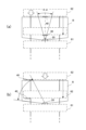
図4(a)には平面視で移動棚装置60の要部が示され、図4(b)には側面視で移動棚装置60の要部が示されている。一方の棚61の奥行き方向(棚に沿う方向)の中央下部に上述した物体検出装置20が設置され、他方の棚62の対向面に基準体40となる反射シートが配されている。棚61,62の底部には床面に敷設された一対のレールRに沿って移動可能なモータ駆動の車輪、モータを制御する駆動回路などが設けられ、棚の側面に設けられた操作スイッチの操作により駆動回路が作動して棚61,62が相対移動可能に構成されている。図4(a)~(c)では一対の棚61,62が例示されているが、実際はそれ以上の複数の棚が設けられ、互いに相対移動可能に構成されている。
[Configuration of device incorporating object detection device]
FIG. 4(a) shows the main parts of the
棚61,62にはそれぞれ表裏両面に個別の収容部が設けられ、棚61,62の間隙空間を広げるように何れか一方の棚を移動することにより、それぞれの対向する収容部にアクセス可能に構成されている。
The
棚61,62の間隙空間に人などが進入した状態で、第三者により棚61,62の間隙空間が狭くなる方向に移動操作された場合に、進入者が棚61,62の間隙空間に挟まれる虞があるため、棚61,62の間隙空間への進入者などの有無を検知するために、棚61,62の一方に物体検出装置20が設置され、棚61,62の他方に基準体40となる反射シートが取り付けられている。
If a person or the like enters the gap space between the
図4(c)に示すように、物体検出装置20は、棚61,62の間隙空間への進入者や進入物などの有無を検出するために、棚61,62の間隙空間が最大のときの床面に平行な二次元平面を覆うように最大の物体検出領域Rが設定されている。しかし、一定の物体検出領域Rであれば、例えば棚62が棚61へ接近する方向に移動する場合に、物体検出装置20により検出される棚62が進入者や進入物として誤検知されることになる。物体検出装置20が設置された棚61が、基準体40が取り付けられた棚62へ接近する方向に移動する場合でも同様である。
As shown in FIG. 4(c), the
そこで、棚61と棚62とが互いに接近する方向に相対移動する場合でも、適切に進入者や進入物の有無を検知できるように、当該物体検出装置20は物体検出領域Rが可変に設定されるように構成されている。また、棚61と棚62とが互いに離隔する方向に相対移動する場合も同様に物体検出領域Rが可変に設定されるように構成されている。
Therefore, the object detection area R of the
[物体検出領域の設定及び物体検出アルゴリズム]
図5には、物体検出領域の設定及び物体検出手順が示されている。測定対象空間に測定光が走査され(S1)、受光部22により1走査分の反射光が受光されると、物体検出装置20から各反射体までの距離Dが距離演算部81で算出される(S2)。
[Object detection area setting and object detection algorithm]
FIG. 5 shows the object detection area setting and object detection procedure. When the measurement light is scanned in the measurement target space (S1) and the reflected light for one scan is received by the
距離演算部81からの出力に基づいて反射体検出部82aにより各反射体の反射体情報、具体的には各反射体に対して反射光強度、距離D、走査方向θ(センターからの振り角)(図4(a)参照。)を含む反射体情報が生成されると(S3)、基準体識別部82bによって反射体が所定の基準体40であるか否かが識別され(S4)、基準体40であると識別されると(S4,Y)、領域画定部82cによって基準体40に沿うように物体検出領域Rが画定される(S5)。
Based on the output from the
物体判定部82dは、物体検出領域Rが画定された後に、ステップS3で生成された各反射体情報に基準体40以外の反射体の情報が存在し(S6)、その反射体が物体検出領域Rに存在する場合に(S7)、物体有りと判定し(S8)、判定結果を移動棚装置60の駆動回路に警告出力する(S9)。移動棚装置60の駆動回路は、当該警告出力に基づき、移動棚の移動を停止または減速制御する。
The object determination unit 82d determines that after the object detection region R is defined, information on a reflector other than the
以下に、詳述する。反射体検出部82aは、距離演算部81で算出された距離が、走査方向が隣接する所定の走査角度範囲で連続して検出され、各距離の差分が所定の閾値以内である場合に反射体であると判定して反射体情報、つまり反射光強度、距離D、走査方向θを生成する。この様なフィルタリング処理により微小な塵埃や羽虫などをノイズとして除去することができるようになる。
This will be explained in detail below. The reflector detection unit 82a detects the reflector when the distances calculated by the
基準体識別部82bは、所定の判定情報に基づいて反射体情報が基準体40であるか否かを判定する。所定の判定情報として反射光強度、走査方向長さ、走査角度などが含まれる。反射光強度は所定の閾値以上の強度であるか否かの判定に用いられ、走査方向長さは走査方向に沿って基準体40に対応する所定の長さを備えているか否かの判定に用いられ、走査角度は所定の走査角度範囲であるか否かの判定に用いられる。これらの判定情報は、単独で用いられてもよいし、組合せて用いられてもよい。
The reference body identification unit 82b determines whether the reflector information is the
図6(a),(b)には、基準体40が再帰性反射シートである場合の例が示されている。再帰性反射シートには、互いに直交する3枚の反射ミラー41,42,43で単位素子が構成される3面体キューブコーナー素子(マイクロプリズムともいう。)が配列されている。この様な3面体キューブコーナー素子に入射した光は、入射方向に向けて反射されるようになるため、通常の散乱体からの反射光強度に比べて極めて高い反射光強度となる。
FIGS. 6A and 6B show an example in which the
従って、反射光強度の閾値を再帰性反射シートであることを示す値に設定することにより、反射体が再帰性反射シートであるか否かを判定することができる。さらに、当該再帰性反射シートの走査方向長さを規定すれば、走査方向長さに亘って所定の閾値以上の反射光強度が維持されている反射体を基準体40と識別することができる。
Therefore, by setting the threshold value of the reflected light intensity to a value indicating that the reflective sheet is a retroreflective sheet, it is possible to determine whether the reflector is a retroreflective sheet. Furthermore, by defining the length of the retroreflective sheet in the scanning direction, a reflector whose reflected light intensity is maintained at a predetermined threshold or higher over the length in the scanning direction can be identified as the
図7(a),(b)には、基準体40が測定光の走査方向に沿って反射光量が段階的に変化する反射特性を備えた反射シートである場合が示されている。
測定光の走査方向に沿って反射光量が段階的にまたは連続的に変化するように、反射面の反射特性を設定することにより、そのような特性を備えていない他の物体との精度の高い識別が可能になる。
FIGS. 7A and 7B show a case where the
By setting the reflection characteristics of the reflective surface so that the amount of reflected light changes stepwise or continuously along the scanning direction of the measurement light, it is possible to achieve high accuracy with other objects that do not have such characteristics. Identification becomes possible.
例えば、図7(a)に示すように、測定光の走査方向に沿って、表面反射率が両端部及び中央部で高く、両端部と中央部の間で低く設定された反射シートを基準体とすれば、それに伴って受光部22で検出される反射光量が走査方向に沿って段階的に変化するため、他の物体からの反射光と確実に識別できるようになる。この様な濃淡パターンを用いてバーコードのようにコード情報化すれば、基準体であるか否かを容易に識別でき、基準体が複数ある場合にはどの基準体であるかを識別することができるようになる。
For example, as shown in FIG. 7(a), a reflective sheet whose surface reflectance is set to be high at both ends and the center and low between both ends and the center along the scanning direction of the measurement light is used as a reference. If so, the amount of reflected light detected by the
例えば、図7(b)に示すように、測定光の走査方向に沿って、表面反射率が鋸刃状に変化するように設定された反射シートを基準体とすれば、それに伴って受光部22で検出される反射光量が走査方向に沿って連続的に上昇し或いは連続的に下降するため、他の物体からの反射光と確実に識別できるようになる。 For example, as shown in FIG. 7(b), if the reference body is a reflective sheet whose surface reflectance is set to change in a sawtooth shape along the scanning direction of the measurement light, the light receiving area Since the amount of reflected light detected at 22 continuously increases or decreases along the scanning direction, it can be reliably distinguished from reflected light from other objects.
また、測定光の走査方向に沿って測定光の波長に対する分光反射特性が段階的にまたは連続的に変化するような反射特性を備えた反射シートを基準体に採用してもよい。この場合、判定情報の一つである反射光強度には、走査方向に沿って変化する所定の強度変化パターンが含まれる。 Further, a reflection sheet having a reflection characteristic such that the spectral reflection characteristic with respect to the wavelength of the measurement light changes stepwise or continuously along the scanning direction of the measurement light may be employed as the reference body. In this case, the reflected light intensity, which is one of the determination information, includes a predetermined intensity change pattern that changes along the scanning direction.
基準体40として、上述したような特別の反射特性を備えた反射シートを用いる以外に、走査方向に沿って連続して反射光が検出され、走査方向に隣接する各走査角度に対する反射光の強度及び距離のそれぞれが所定の閾値内である場合に連続体であると判定し、当該連続体を基準体として判定してもよい。また、1走査内で複数の連続体が検出され、各連続体の延長線が互いに重なるような場合に、各連続体が一つの基準体であると判定してもよい。
In addition to using a reflective sheet with special reflective properties as described above as the
図9(a)に示すように、図4(a),(b)で示した基準体40に替えて、棚62の表面自体を基準体40とするような態様が該当する。所定の方向に連続する反射体を基準体と認識するのである。図9(a)の場合には、所定の方向とは、床面に平行で、振り角θが0度(センター)の測定光の光軸に直交する方向をいう。当該所定の方向に予め定めた長さ(例えば棚62の奥行長さの8割程度の長さ)だけ連続して反射体が検出された場合に基準体40と識別することができる。
As shown in FIG. 9A, an embodiment in which the surface of the
例えば、仮に移動棚61,62の間に進入者が存在して、棚62の表面からの反射が進入者により遮断される様な場合でも、当該進入者に相当する反射体を除いた反射体の端部を接続した場合に1本の連続線として重畳されるような関係にあれば、棚62の表面つまり基準体40と識別できる。
For example, even if an intruder exists between the
図9(a)の例では、床面に平行で、振り角θが0度(センター)の測定光の光軸に直交する方向を所定方向としたが、所定方向はこのような例に限るものではなく、図9(b)に示すように、床面に平行で、振り角θが0度(センター)の測定光の光軸に90度以外の所定角度で交差するような傾斜面にであってもよい。なお、床面に平行とするのは測定光の走査面が床面に平行な面であるためであり、測定光の走査面と平行であれば、床面に平行でなくともよい。 In the example of FIG. 9(a), the predetermined direction is a direction that is parallel to the floor and perpendicular to the optical axis of the measurement light where the swing angle θ is 0 degrees (center), but the predetermined direction is limited to such an example. As shown in Fig. 9(b), the slope is parallel to the floor and intersects the optical axis of the measurement light with a swing angle θ of 0 degrees (center) at a predetermined angle other than 90 degrees. It may be. Note that the reason why it is parallel to the floor surface is because the scanning plane of the measurement light is a plane parallel to the floor surface, and as long as it is parallel to the scanning plane of the measurement light, it does not have to be parallel to the floor surface.
また、基準体40は平面に限るものではなく任意の曲率の曲面であってもよい。この場合には、走査方向に沿って連続して反射光が検出され、走査方向に隣接する各走査角度に対する反射光の強度及び距離のそれぞれが所定の閾値内であり、各反射体を連結した線分が所定の曲率であれば、基準体40であると判定すればよい。つまり所定の判定情報にさらに曲率が含まれることになる。
Furthermore, the
図4(a),(b)の例では、基準体40が棚62の奥行き方向中央下部に配された例を示したが、図8(b)に示すように、基準体40が棚62の奥行き方向下部の左右何れかの端部に取り付けられていてもよいし、奥行き方向下部の手前から奥側にかけて複数個所に設けられていてもよい。
In the examples shown in FIGS. 4(a) and 4(b), the
基準体40と同様の反射特性を備えた物体を基準体と誤認識しないために、基準体40を判別する領域を所定の識別範囲に限定することが好ましい。図8(a),(b)には、基準体識別部82bが、反射体が基準体40であるか否かを判定する所定の識別範囲として用いられる走査角度(走査角度範囲)の例が示されている。例えば、図8(a)のように、床面に平行で、振り角θが0度(センター)の測定光の光軸上に基準体40の左右幅方向の中心が位置するような場合に、物体検出装置20から最も離隔した位置で基準体40の幅方向の全域が検出されるように、0度の測定光の光軸を中心に±αの角度の範囲を識別範囲に設定することができる。識別範囲外すなわち±αの角度の範囲以外の走査角度で基準体40と同様の反射特性を備えた物体が存在しても基準体40であると誤って判定することがない。
In order to prevent an object having the same reflection characteristics as the
例えば、測定光が0.125度/ステップで走査される場合に、±10ステップの走査角度範囲を識別範囲に設定すると、振り角θが0度(センター)の測定光の光軸に対して±1.25度の範囲に存在する基準体40を識別できるようになる。
For example, when the measurement light is scanned at 0.125 degrees/step, if the scanning angle range of ±10 steps is set as the identification range, the swing angle θ is relative to the optical axis of the measurement light at 0 degrees (center). The
走査角度範囲の設定によっては、基準体40が物体検出装置20に近接する場合に、基準体40の幅方向の全域が検出できない場合も生じるが、その場合には少なくとも±αの角度の範囲で連続して検出される反射体を基準体40と識別することができる。
Depending on the setting of the scanning angle range, when the
例えば、図8(b)の場合には、物体検出装置20から基準体40までの距離にかかわらず広い走査角度範囲を識別範囲に設定することにより、距離の変化による基準体40の走査角度の偏りによる影響を排除することができる。
For example, in the case of FIG. 8(b), by setting a wide scanning angle range as the identification range regardless of the distance from the
この様に基準体40が物体検出装置20に近接する場合でも、基準体40の幅方向の全域が検出されるように、走査角度範囲を設定することも可能であるし、物体検出装置20から基準体40までの距離に基づいて走査角度範囲を可変設定することで基準体40の識別精度を高めてもよい。例えば、物体検出装置20からの離隔時には近接時より走査角度範囲を狭くすればよい。即ち、基準体識別部82bは測定光の走査範囲より狭い所定の識別範囲に存在する反射体を基準体40の識別対象とすることになる。識別範囲は走査角度範囲のみに限定されるものではなく、走査角度範囲及び距離を組み合わせた任意の形状となるように設定することも可能である。
Even when the
図10(a),(b)には、移動棚装置60を例にして、領域画定部82cにより画定された物体検出領域Rが示されている。領域画定部82cは、基準体40に対して相対的に遠近方向に移動可能な構造体に設けられた物体検出装置20と当該基準体40が取り付けられた構造体との間に形成される空間に、少なくとも基準体40に沿うように物体検出領域Rを動的に画定する。物体検出領域Rは少なくとも基準体40の面の延出方向に沿う面が含まれる。面状の基準体40の延出方向に沿う面が物体検出領域Rに含まれるため、基準体40の延出方向面と物体検出領域Rとが重複することなく、従って基準体40の延出方向面が誤って物体として検出されることが回避される。
FIGS. 10A and 10B show an object detection area R defined by the area defining section 82c using the
棚62が棚61から最も離隔した位置にある場合の物体検出領域Rmaxとし、基準体40を介して棚62の棚61への近接距離Dを把握し、物体検出装置20から基準体40の延在方向に沿って物体検出領域Rmaxよりも狭い物体検出領域R1を画定する。物体検出装置20から視て棚62と棚61の間に形成される空間のうち左右方向に延びる空間全域を物体検出領域Rに含める必要はないため、棚61,62の奥行長さから僅かな長さだけさらに奥側及び手前側に延出する範囲を物体検出領域Rとしている。
The object detection area Rmax is defined as the case where the
物体検出領域R1は物体検出装置20から基準体40までの距離を基準にして、物体検出装置20の側に所定のオフセットR2が付与されていることが好ましい。この場合、オフセットR2は基準体40までの距離よりも短くなるように負の値となる。
It is preferable that the object detection region R1 is provided with a predetermined offset R2 on the side of the
基準体40の反射面の特性によっては反射体検出部82aにより検出された距離Dに誤差が生じる場合があり、物体検出領域Rに基準体40が物体として誤検出される虞がある。そのような場合でも基準体40までの距離を基準に物体検出装置20側に所定のオフセットR2が付与されることで、物体検出領域R1から基準体を確実に除外することができる。オフセットR2の値は距離測定のバラツキ、棚62の凹凸状態、その他を考慮して適宜設定すればよい。
Depending on the characteristics of the reflective surface of the
また、物体検出領域R1は物体検出装置20から基準体40までの距離Dにかかわらず物体検出装置20側に所定の固定領域R3が画定されていることが好ましい。基準体40が物体検出装置20の近傍に接近するような場合に、固定領域R3が画定されていれば物体検出領域Rが不必要に狭くなることが回避され、棚61、棚62間の必要最低限の所定のスペースが確保される。
Further, it is preferable that the object detection region R1 is a predetermined fixed region R3 defined on the
図10(c)に示すように、物体検出領域R1は、物体検出装置20からの離隔の程度に応じて領域分割され、分割された領域Ra,Rb,Rc毎に物体の検出情報が移動棚装置60などの外部装置に出力されることが好ましい。人や物が検出された分割領域に応じて棚62の移動を直ちに停止する必要があるのか、進入者の領域外への移動を促すべく、移動速度を減速するだけで良い場合など、適切な対応が可能になる。なお、図10(c)では、基準体40が棚62の奥行方向に沿って手前側と奥側の2か所に設けられている。
As shown in FIG. 10(c), the object detection region R1 is divided into regions according to the degree of separation from the
また、領域Ra,Rb,Rcの三領域を領域RAとし、領域Rb,Rcの二領域を領域RBとし、領域Rcを領域RCと設定するように、領域画定部82cにより少なくとも一部が重複する複数の物体検出領域RA,RB,RCを画定するように構成してもよい。 Further, the area defining unit 82c sets at least a portion of the area so that the three areas Ra, Rb, and Rc are set as the area RA, the two areas Rb and Rc are set as the area RB, and the area Rc is set as the area RC. It may be configured to define a plurality of object detection areas RA, RB, and RC.
この場合、何れかの物体検出領域RA,RB,RCに検出対象物体が存在し、しかも検出対象物体が重複領域に存在する場合に、物体判定部82dは、重複領域の其々に検出対象物体が存在すると判定する第1判定モードと、重複領域のうち特定の領域にのみ検出対象物体が存在すると判定する第2判定モードの何れかに切替設定可能に構成されていることが好ましい。そのための切替スイッチを物体検出装置20に備えていてもよいし、コンピュータ等の設定治具を物体検出装置20に接続して切替操作してもよい。また、物体検出領域RA,RB,RC毎に第1判定モードと第2判定モードを切替可能に構成されていてもよい。
In this case, if a detection target object exists in any of the object detection regions RA, RB, RC, and the detection target object exists in an overlapping region, the object determination unit 82d detects the detection target object in each of the overlapping regions. It is preferable to be configured to be able to switch between a first determination mode in which it is determined that a detection target object exists, and a second determination mode in which it is determined that a detection target object exists only in a specific region among the overlapping regions. The
例えば、第1判定モードに設定されている場合に、物体検出領域Rcに検出対象物体が存在すると、物体判定部82dは物体検出領域RA,RB,RCの全てに検出対象物体が存在すると判定し、物体検出領域Rbに検出対象物体が存在すると、物体判定部82dは物体検出領域RA,RBに検出対象物体が存在すると判定する。 For example, when the first determination mode is set and a detection target object exists in the object detection area Rc, the object determination unit 82d determines that the detection target object exists in all of the object detection areas RA, RB, and RC. , when the object to be detected exists in the object detection area Rb, the object determination unit 82d determines that the object to be detected exists in the object detection areas RA, RB.
例えば、第2判定モードに設定されている場合に、物体検出領域Rcに検出対象物体が存在すると、物体判定部82dは物体検出領域RCにのみ検出対象物体が存在すると判定し、物体検出領域Rbに検出対象物体が存在すると、物体判定部82dは物体検出領域RBにのみ検出対象物体が存在すると判定する。 For example, when the second determination mode is set and the object to be detected exists in the object detection region Rc, the object determination section 82d determines that the object to be detected exists only in the object detection region RC, and If the object to be detected exists in the object detection area RB, the object determination unit 82d determines that the object to be detected exists only in the object detection region RB.
重複領域に検出対象物体が存在する場合に、物体検出装置20に近い側の物体検出領域を優先して検出対象物体が存在すると判定する態様となる。物体検出装置20に近い側と遠い側とで対処が異なる場合に好適となる。例えば、物体検出領域Raのみに検出対象物体が存在する場合には僅かに棚の移動速度を落とし、物体検出領域Rbのみに検出対象物体が存在する場合には棚の移動速度を大きく落とし、物体検出領域Rcのみに検出対象物体が存在する場合には棚を停止するといったように対処できる。
When a detection target object exists in the overlapping region, priority is given to the object detection region closer to the
必要な領域にのみ検出対象物体が存在すると判定することが可能となり、判定処理のための演算負荷が軽減される。また、其々の態様に応じて適切に棚を移動制御できる。 It becomes possible to determine that the object to be detected exists only in the necessary area, and the calculation load for the determination process is reduced. Further, the movement of the shelves can be controlled appropriately according to each aspect.
図14には、物体検出領域RA,RB毎に第1判定モードと第2判定モードを切り替える場合の判定出力が例示されている。なお、図14では第1判定モードを第1モードと表記し、第2判定モードを第2モードと表記している。 FIG. 14 illustrates a determination output when switching between the first determination mode and the second determination mode for each object detection area RA, RB. Note that in FIG. 14, the first determination mode is referred to as a first mode, and the second determination mode is referred to as a second mode.
上述した実施形態では、基準体識別部82bが所定の基準体を識別することを前提とする場合を説明している。しかし実際の使用環境にあっては、外来光によるノイズの影響や、大きな進入物により基準体が被覆される場合等、様々な要因で所定の基準体を特定できない場合も想定する必要がある。 In the embodiment described above, a case has been described on the premise that the reference body identifying section 82b identifies a predetermined reference body. However, in the actual environment of use, it is necessary to assume that the predetermined reference body may not be identified due to various factors, such as the influence of noise from external light or the case where the reference body is covered by a large intruding object.
そのような場合に備えて、基準体識別部82bが測定対象空間に存在する基準体を識別することができない場合に、物体判定部82dは反射体の有無にかかわらず物体検出領域に検出対象物体が存在すると判定する非検出出力モードを備えていることが好ましい。非検出出力モードを有効にするか否かの切替スイッチを物体検出装置20に備えていてもよいし、コンピュータ等の設定治具を物体検出装置20に接続して切替操作してもよい。
In preparation for such a case, when the reference object identification unit 82b cannot identify the reference object existing in the measurement target space, the object determination unit 82d detects the object to be detected in the object detection area regardless of the presence or absence of a reflector. It is preferable to include a non-detection output mode in which it is determined that . The
非検出出力モードに設定することにより、所定の基準体が特定できない場合に、物体判定部82dが物体検出領域に検出対象物体が存在すると判定するため、棚を停止させ、或いは移動速度を低減する等の安全対策が可能になる。 By setting to the non-detection output mode, when the predetermined reference object cannot be identified, the object determination unit 82d determines that a detection target object exists in the object detection area, so the shelf is stopped or the moving speed is reduced. It becomes possible to take safety measures such as
上述した実施形態に加えて、物体検出装置20の光走査機構23に、測定光の光路に第1方向へ振動する光のみを透過する偏光子と、反射光の光路に第1方向と直交する第2方向へ振動する光のみを透過する検光子とが設けられていてもよい。
In addition to the embodiments described above, the
図12に示すように、光走査機構23に組み込まれた光ガイド部54のうち、光学窓20Cと対向する位置で、測定光光路L1の出口端部に上述の偏光子PLが配され、反射光光路L2の入口端部に上述の検光子ANが配されている。つまり、偏光子PLが光ガイド部54の内側に配され、検光子ANが光ガイド部54の外側に配されている。また、光の出射方向に沿って投光レンズ24の直後の位置に円偏光板の一例である1/4波長板28が配置されている。
As shown in FIG. 12, the above-mentioned polarizer PL is arranged at the exit end of the measurement light optical path L1 at a position facing the
発光部21のレーザダイオードから出射され、所定方向に直線偏光する測定光が、1/4波長板28を通過することにより円偏光に変化し、さらに偏光子PLを通過することにより、例えば走査方向に対して直交する方向の直線偏光に変化する。
Measurement light emitted from the laser diode of the
偏光子PLや検光子ANとしてガラスの表面上に微細な金属のグリッドを形成したワイヤーグリッドや、材料自体の持つ複屈折現象を利用して偏光成分を調節する結晶性材料などを用いることができる。 As the polarizer PL and analyzer AN, wire grids in which fine metal grids are formed on the surface of glass, crystalline materials that adjust the polarization component by utilizing the birefringence phenomenon of the material itself, etc. can be used. .
基準体40の反射面に偏光方向を90度回転させるような光学部材を配置することにより、測定光の偏光方向に対して反射光の偏光方向が90度回転するようになる。この様な光学部材として、先に説明した3面体キューブコーナー素子が配列された再帰性反射シートや1/2波長板が好適に用いられる。
By arranging an optical member that rotates the polarization direction by 90 degrees on the reflective surface of the
図6(b)に示すように、偏光子PLを通過して縦方向に直線偏光する測定光が、3面体キューブコーナー素子の3面で反射されることにより90度偏光方向が変化した直線偏光となり、検光子ANを通過するようになる。 As shown in FIG. 6(b), the measurement light that passes through the polarizer PL and is linearly polarized in the vertical direction is reflected by three surfaces of the trihedral cube corner element, resulting in linearly polarized light whose polarization direction is changed by 90 degrees. Therefore, the light passes through the analyzer AN.
偏光子PLを通過した測定光がアルミなどの金属板に反射しても、反射光の偏光方向は変化することがないため、反射光が検光子ANを通過することはない。偏光子PLを通過した測定光が白色散乱板に反射すると、偏光方向が乱されて円偏光や様々な角度方向への直線偏光が重なった反射光となるため、検光子ANを通過する反射光の光量はおよそ半減する。 Even if the measurement light that has passed through the polarizer PL is reflected by a metal plate such as aluminum, the polarization direction of the reflected light does not change, so the reflected light does not pass through the analyzer AN. When the measurement light that has passed through the polarizer PL is reflected on the white scattering plate, the polarization direction is disturbed and the reflected light is a combination of circularly polarized light and linearly polarized light in various angular directions, so the reflected light that passes through the analyzer AN is The amount of light will be approximately halved.
光走査機構23に偏光子PLと検光子ANを備え、偏向ミラー52と一体に回転するので、走査に伴って出射する測定光の偏向方向が変化することがなく、また入射した反射光の偏向方向が変化することもない。捕捉対象物である基準体の反射面の反射特性が測定光の偏向方向を90度回転させるような反射特性を備えていれば、確実に捕捉対象物であると識別できるようになる。
The
図13には、物体検出装置20の光走査機構23の他の例が示されている。光走査機構23に組み込まれた光ガイド部54のうち、発光部21と対向する位置で、測定光光路L1の入口端部に上述の偏光子PLが配され、偏向ミラー52によって偏向された反射光光路L2の出口端部に上述の検光子ANが配されている。
FIG. 13 shows another example of the
図11には、図2に示した物体検出装置20で、図6に示した再帰性反射シート(基準体)を検出する場合の反射光強度特性(実線で示す)が示されている。基準体が物体検出装置20に遠方から近接する程に反射光の検出光量が上昇するが、極めて近傍まで近接すると、光ガイド部54から出射され基準体から反射した反射光の大半が光ガイド部54に入射し、偏向ミラー52に入射する光量が低下するため、逆に急激に低下する。また、標準白色紙であるケント紙に対する反射光量は一点鎖線で示されているように基準体とは大きく異なる。
FIG. 11 shows reflected light intensity characteristics (indicated by a solid line) when the retroreflective sheet (reference body) shown in FIG. 6 is detected by the
そこで、反射光が基準体であると検出するための反射光量の閾値を、実線で示した反射光強度特性から一律に一定値を減算した特性(破線で示す)を基準にして、急激に強度が低下する直前の500mmの強度と中間の10000mmの強度を結ぶ線分、及び中間の10000mmの強度と遠方の20000mmの強度を結ぶ線分を閾値として基準体であるか否かを識別するように構成されている。 Therefore, the threshold value of the amount of reflected light for detecting that the reflected light is a reference object is set based on the characteristic (indicated by the broken line) obtained by uniformly subtracting a constant value from the reflected light intensity characteristic indicated by the solid line. The line segment connecting the 500 mm intensity immediately before the drop and the intermediate 10,000 mm intensity, and the line segment connecting the intermediate 10,000 mm intensity and the distant 20,000 mm intensity are used as thresholds to identify whether or not it is a reference object. It is configured.
なお、物体検出装置20の反射光検出特性及び基準体の反射特性に基づいて当該閾値は適宜調整可能であることは言うまでもない。
It goes without saying that the threshold value can be adjusted as appropriate based on the reflected light detection characteristics of the
上述した実施形態では、物体検出装置20が床面と平行な平面に沿って測定光が二次元的に走査される場合を説明したが、床面と垂直な平面に沿って測定光が二次元的に走査されるように構成されていてもよい。例えば水平方向または垂直方向に自動開閉する扉体を備えた自動ゲートなどに人や物が挟まれるような危険な状態を検出して事故を未然に防止することができる。
In the embodiment described above, a case has been described in which the
また、測定光が三次元的に走査可能な物体検出装置20であれば、三次元空間に配置された基準体との間で立体的な物体検出領域Rを画定することができる。例えば、図2に示した物体検出装置20を光軸Pと直交する回転軸周りに回転可能に構造体に取付けることにより、測定光を三次元的に走査することができる。
Further, if the
上述した実施形態は、移動棚装置に組み込まれた物体検出装置20と基準体40について説明したが、物体検出装置20が組み込まれる装置は移動棚装置に限るものではなく、物体検出装置20に対して相対的に移動する移動体との間に形成される空間に進入する人や物を検出して、危険な状況を回避する必要がある任意の装置に適用可能である。例えば、フォークリフトに物体検出装置20が搭載され、運転者の死角となる後方を監視する場合に、フォークリフトとフォークリフトの後方に配置された壁や棚等の構造体との間を監視する場合などに応用できる。また、無人搬送車AGV(automatic guided vehicle)等にも物体検出装置20を搭載することができる。
In the embodiment described above, the
上述した実施形態では、検出した基準体に基づいて領域画定部が物体検出領域を画定する例を説明したが、予め物体検出領域が設定されている場合であっても、物体判定部82dを第1判定モードと第2判定モードに切り替えるように構成することは可能である。 In the embodiment described above, an example has been described in which the region defining section defines the object detection region based on the detected reference body, but even if the object detection region is set in advance, the object determining section 82d may be It is possible to configure the system to switch between the first determination mode and the second determination mode.
測定対象空間に存在する物体を検出する物体検出装置であって、発光部から出射された測定光を測定対象空間に走査し、測定光に対する反射体からの反射光を受光部に導く光走査部と、測定光と反射光の物理的特性に基づいて算出される物体検出装置から反射体までの距離と、受光部で検出される反射光強度と、測定光の走査方向と、を含む反射体情報を検出する反射体検出部と、少なくとも一部が重複する複数の物体検出領域を画定する領域画定部と、前記反射体検出部で検出された反射体情報に基づいて、何れかの重複する物体検出領域に検出対象物体が存在するか否かを判定する物体判定部を備え、物体判定部は、検出対象物体が存在する重複領域の全てに検出対象物体が存在すると判定するか、重複領域のうち特定の領域にのみ検出対象物体が存在すると判定するか、の何れかに切替設定可能に構成されていればよい。 An object detection device that detects an object existing in a measurement target space, comprising: a light scanning unit that scans measurement light emitted from a light emitting unit into the measurement target space and guides reflected light from a reflector for the measurement light to a light receiving unit; , the distance from the object detection device to the reflector calculated based on the physical characteristics of the measurement light and the reflected light, the reflected light intensity detected by the light receiving section, and the scanning direction of the measurement light. a reflector detection section that detects information; an area definition section that defines a plurality of object detection regions that at least partially overlap; It includes an object determination unit that determines whether or not a detection target object exists in the object detection area, and the object determination unit determines that the detection target object exists in all of the overlapping areas where the detection target object exists, or determines whether the detection target object exists in all the overlapping areas where the detection target object exists, or It is only necessary to be configured to be able to switch between determining that the object to be detected exists only in a specific area.
この場合、反射体検出部で検出された反射体が上述した実施形態の基準体であるか否かを識別する必要はなく、全ての反射体が検出対象物となる。従って、基準体の反射体情報に基づいて物体検出領域を画定するようなことはなく、物体検出領域は予め設定されることになる。また、反射体情報は、物体検出装置から反射体までの距離と、受光部で検出される反射光強度と、測定光の走査方向を含むことになるが、基準体を識別するような目的で反射光強度を使用するのではなく、単にノイズ光を排除する閾値以上の反射光強度であることを担保する程度の意味である。従って、事前の処理でノイズ光を排除できるのであれば、反射体情報に反射光強度を含める必要はない。 In this case, it is not necessary to identify whether or not the reflector detected by the reflector detection section is the reference object of the embodiment described above, and all reflectors become detection targets. Therefore, the object detection area is not defined based on the reflector information of the reference body, and the object detection area is set in advance. In addition, the reflector information includes the distance from the object detection device to the reflector, the intensity of the reflected light detected by the light receiving section, and the scanning direction of the measurement light, but it is not used for purposes such as identifying the reference object. This does not mean using the intensity of reflected light, but simply ensuring that the intensity of reflected light is equal to or higher than a threshold for eliminating noise light. Therefore, if noise light can be eliminated through prior processing, there is no need to include reflected light intensity in the reflector information.
以上説明した実施形態は何れも本発明の一実施例に過ぎず、当該記載により本発明の範囲が限定されるものではなく、各部の具体的構成は本発明による作用効果を奏する範囲において適宜変更することができることは言うまでもない。 The embodiments described above are merely examples of the present invention, and the scope of the present invention is not limited by the descriptions, and the specific configuration of each part may be changed as appropriate within the scope of achieving the effects of the present invention. It goes without saying that you can.
20:物体検出装置
21:発光部
22:受光部
23:光走査機構
24:投光レンズ
25:受光レンズ
23,24,25:光走査部
82:物体検出部
82a:反射体検出部
82b:基準体識別部
82c:領域画定部
82d:物体判定部
20: Object detection device 21: Light emitting unit 22: Light receiving unit 23: Light scanning mechanism 24: Light projecting lens 25:
Claims (7)
発光部から出射された測定光を測定対象空間に走査し、前記測定光に対する反射体からの反射光を受光部に導く光走査部と、
前記測定光と前記反射光の物理的特性に基づいて算出される前記物体検出装置から反射体までの距離と、前記受光部で検出される反射光強度と、前記測定光の走査方向と、を含む反射体情報を検出する反射体検出部と、
前記反射体検出部で検出された反射体情報に基づいて、前記反射体が所定の基準体であるか否かを識別する基準体識別部と、
前記基準体識別部により識別された基準体の反射体情報に基づいて、当該基準体に沿うように物体検出領域を画定する領域画定部と、
前記領域画定部により画定された物体検出領域に存在し、前記基準体識別部により基準体と識別されなかった反射体を検出対象物体であると判定する物体判定部と、
を備え、
相対的に遠近方向に移動可能な構造体の一方に前記基準体が設けられ、他方に前記物体検出装置が設けられ、
前記領域画定部は、前記構造体の相対移動に伴って、前記物体検出装置と前記基準体との間に形成される空間に前記物体検出領域を動的に画定する物体検出装置。 An object detection device that detects an object existing in a measurement target space,
a light scanning unit that scans the measurement light emitted from the light emitting unit into the measurement target space and guides the reflected light from the reflector for the measurement light to the light receiving unit;
a distance from the object detection device to the reflector calculated based on the physical characteristics of the measurement light and the reflected light; a reflected light intensity detected by the light receiving section; and a scanning direction of the measurement light. a reflector detection unit that detects reflector information including;
a reference body identification unit that identifies whether or not the reflector is a predetermined reference body based on reflector information detected by the reflector detection unit;
an area defining unit that defines an object detection area along the reference body based on reflector information of the reference body identified by the reference body identification unit;
an object determining unit that determines that a reflector that is present in the object detection area defined by the area defining unit and is not identified as a reference body by the reference body identifying unit is an object to be detected;
Equipped with
The reference body is provided on one side of a structure that is relatively movable in a far and near direction, and the object detection device is provided on the other side,
The area defining unit is an object detection device that dynamically defines the object detection area in a space formed between the object detection device and the reference body as the structure moves relative to each other.
When the reference body identification unit cannot identify the reference body existing in the measurement target space, the object determination unit determines that the detection target object exists in the object detection area regardless of the presence or absence of the reflector. 7. The object detection device according to claim 1, further comprising a non-detection output mode.
Applications Claiming Priority (3)
| Application Number | Priority Date | Filing Date | Title |
|---|---|---|---|
| JP2018237871 | 2018-12-20 | ||
| JP2018237871 | 2018-12-20 | ||
| PCT/JP2019/047992 WO2020129720A1 (en) | 2018-12-20 | 2019-12-09 | Object detection device |
Publications (3)
| Publication Number | Publication Date |
|---|---|
| JPWO2020129720A1 JPWO2020129720A1 (en) | 2021-11-04 |
| JPWO2020129720A5 JPWO2020129720A5 (en) | 2022-11-24 |
| JP7378825B2 true JP7378825B2 (en) | 2023-11-14 |
Family
ID=71102795
Family Applications (1)
| Application Number | Title | Priority Date | Filing Date |
|---|---|---|---|
| JP2020561315A Active JP7378825B2 (en) | 2018-12-20 | 2019-12-09 | object detection device |
Country Status (6)
| Country | Link |
|---|---|
| US (1) | US20220018966A1 (en) |
| JP (1) | JP7378825B2 (en) |
| KR (1) | KR20210104667A (en) |
| CN (1) | CN113167904A (en) |
| DE (1) | DE112019006362T5 (en) |
| WO (1) | WO2020129720A1 (en) |
Families Citing this family (3)
| Publication number | Priority date | Publication date | Assignee | Title |
|---|---|---|---|---|
| USD975560S1 (en) * | 2021-02-04 | 2023-01-17 | Argo AI, LLC | Sensor housing |
| USD994094S1 (en) | 2021-02-04 | 2023-08-01 | Lg Innotek Co., Ltd. | Sensor housing |
| CN115359183B (en) * | 2022-08-16 | 2023-05-09 | 中建一局集团第五建筑有限公司 | Three-dimensional model representation device |
Citations (6)
| Publication number | Priority date | Publication date | Assignee | Title |
|---|---|---|---|---|
| WO2003075035A1 (en) | 2002-03-01 | 2003-09-12 | Hitachi, Ltd. | Detection system |
| JP2004355551A (en) | 2003-05-30 | 2004-12-16 | Matsushita Electric Works Ltd | Protection system |
| JP2010216946A (en) | 2009-03-16 | 2010-09-30 | Denso Wave Inc | Laser distance measuring device |
| JP2015138026A (en) | 2014-01-24 | 2015-07-30 | ジック アーゲー | Method of configuring laser scanner and configuration object therefore |
| JP2017043461A (en) | 2015-08-27 | 2017-03-02 | 株式会社ダイフク | Moving rack device and control method of moving rack device |
| JP2017151569A (en) | 2016-02-22 | 2017-08-31 | 株式会社キーエンス | Safety scanner and optical safety system |
Family Cites Families (7)
| Publication number | Priority date | Publication date | Assignee | Title |
|---|---|---|---|---|
| JP2910245B2 (en) * | 1990-12-11 | 1999-06-23 | 株式会社豊田自動織機製作所 | Driverless vehicle safety devices |
| JPH05288847A (en) * | 1992-04-09 | 1993-11-05 | Nissan Motor Co Ltd | Approach detection apparatus |
| JP2002215238A (en) | 2001-01-16 | 2002-07-31 | Hokuyo Automatic Co | Obstruction detection sensor for unmanned carrier |
| JP3443106B2 (en) * | 2001-04-27 | 2003-09-02 | 三菱重工業株式会社 | Floating object detection / monitoring method and device |
| JP2005233716A (en) * | 2004-02-18 | 2005-09-02 | Omron Corp | Radar device |
| JP2008286565A (en) * | 2007-05-16 | 2008-11-27 | Omron Corp | Body detector |
| JP6647524B2 (en) * | 2015-10-27 | 2020-02-14 | 北陽電機株式会社 | Area sensor and external storage device |
-
2019
- 2019-12-09 US US17/295,779 patent/US20220018966A1/en active Pending
- 2019-12-09 WO PCT/JP2019/047992 patent/WO2020129720A1/en active Application Filing
- 2019-12-09 CN CN201980077836.2A patent/CN113167904A/en active Pending
- 2019-12-09 DE DE112019006362.6T patent/DE112019006362T5/en active Pending
- 2019-12-09 JP JP2020561315A patent/JP7378825B2/en active Active
- 2019-12-09 KR KR1020217015126A patent/KR20210104667A/en unknown
Patent Citations (6)
| Publication number | Priority date | Publication date | Assignee | Title |
|---|---|---|---|---|
| WO2003075035A1 (en) | 2002-03-01 | 2003-09-12 | Hitachi, Ltd. | Detection system |
| JP2004355551A (en) | 2003-05-30 | 2004-12-16 | Matsushita Electric Works Ltd | Protection system |
| JP2010216946A (en) | 2009-03-16 | 2010-09-30 | Denso Wave Inc | Laser distance measuring device |
| JP2015138026A (en) | 2014-01-24 | 2015-07-30 | ジック アーゲー | Method of configuring laser scanner and configuration object therefore |
| JP2017043461A (en) | 2015-08-27 | 2017-03-02 | 株式会社ダイフク | Moving rack device and control method of moving rack device |
| JP2017151569A (en) | 2016-02-22 | 2017-08-31 | 株式会社キーエンス | Safety scanner and optical safety system |
Also Published As
| Publication number | Publication date |
|---|---|
| WO2020129720A1 (en) | 2020-06-25 |
| US20220018966A1 (en) | 2022-01-20 |
| KR20210104667A (en) | 2021-08-25 |
| JPWO2020129720A1 (en) | 2021-11-04 |
| CN113167904A (en) | 2021-07-23 |
| DE112019006362T5 (en) | 2021-09-09 |
Similar Documents
| Publication | Publication Date | Title |
|---|---|---|
| JP7378825B2 (en) | object detection device | |
| JP7214195B2 (en) | Object capture device, captured object, and object capture system | |
| JP7425510B2 (en) | object capture device | |
| JP5644437B2 (en) | Distance measuring device and distance measuring method | |
| JPWO2020129720A5 (en) | ||
| US20110128525A1 (en) | Light scanning device, laser radar device, and light scanning method | |
| JP2006038854A (en) | Laser scanning and sensing device for detection around automatic door | |
| US20070216878A1 (en) | Distance measuring device and laser beam projector therefor | |
| US20190107622A1 (en) | Scanning LiDAR System and Method with Source Laser Beam Splitting Apparatus and Method | |
| JP7151519B2 (en) | Distance image measuring device | |
| JP2009236774A (en) | Three dimensional ranging device | |
| KR101737535B1 (en) | A improved laser range finder device | |
| US20220289026A1 (en) | Object Detection Sensor Alignment | |
| JP2007031103A5 (en) | ||
| JP4379790B2 (en) | Device for scanning a scene | |
| JP2004170128A (en) | Sensor | |
| US7209272B2 (en) | Object detecting apparatus having operation monitoring function | |
| JPH0829536A (en) | Method and apparatus for detecting optical axis | |
| JPH06289138A (en) | Obstacle detecting device | |
| JP6412352B2 (en) | Automatic mobile vehicle and automatic mobile vehicle control system | |
| EP4231046A1 (en) | System for measuring a distance to an object from behind a transparent element | |
| WO2021235317A1 (en) | Optical distance measurement device | |
| WO2023066472A1 (en) | Robotic system comprising an environment sensor | |
| JPH0611341A (en) | Optical apparatus for measuring distance | |
| JPH06249957A (en) | Area sensor |
Legal Events
| Date | Code | Title | Description |
|---|---|---|---|
| A521 | Request for written amendment filed |
Free format text: JAPANESE INTERMEDIATE CODE: A523 Effective date: 20221115 |
|
| A621 | Written request for application examination |
Free format text: JAPANESE INTERMEDIATE CODE: A621 Effective date: 20221115 |
|
| A131 | Notification of reasons for refusal |
Free format text: JAPANESE INTERMEDIATE CODE: A131 Effective date: 20230801 |
|
| A521 | Request for written amendment filed |
Free format text: JAPANESE INTERMEDIATE CODE: A523 Effective date: 20230915 |
|
| TRDD | Decision of grant or rejection written | ||
| A01 | Written decision to grant a patent or to grant a registration (utility model) |
Free format text: JAPANESE INTERMEDIATE CODE: A01 Effective date: 20231024 |
|
| A61 | First payment of annual fees (during grant procedure) |
Free format text: JAPANESE INTERMEDIATE CODE: A61 Effective date: 20231025 |
|
| R150 | Certificate of patent or registration of utility model |
Ref document number: 7378825 Country of ref document: JP Free format text: JAPANESE INTERMEDIATE CODE: R150 |