JP7371670B2 - Imaging device, program, and display method of subject images - Google Patents
Imaging device, program, and display method of subject images Download PDFInfo
- Publication number
- JP7371670B2 JP7371670B2 JP2021104268A JP2021104268A JP7371670B2 JP 7371670 B2 JP7371670 B2 JP 7371670B2 JP 2021104268 A JP2021104268 A JP 2021104268A JP 2021104268 A JP2021104268 A JP 2021104268A JP 7371670 B2 JP7371670 B2 JP 7371670B2
- Authority
- JP
- Japan
- Prior art keywords
- subject image
- range
- display
- enlargement
- representative point
- Prior art date
- Legal status (The legal status is an assumption and is not a legal conclusion. Google has not performed a legal analysis and makes no representation as to the accuracy of the status listed.)
- Active
Links
- 238000003384 imaging method Methods 0.000 title claims description 106
- 238000000034 method Methods 0.000 title claims description 61
- 230000009467 reduction Effects 0.000 claims description 140
- 238000012545 processing Methods 0.000 claims description 83
- 230000004044 response Effects 0.000 claims description 45
- 238000010586 diagram Methods 0.000 description 44
- 230000004048 modification Effects 0.000 description 30
- 238000012986 modification Methods 0.000 description 30
- 230000006870 function Effects 0.000 description 27
- 230000008569 process Effects 0.000 description 25
- 238000000605 extraction Methods 0.000 description 18
- 238000013459 approach Methods 0.000 description 17
- 239000000284 extract Substances 0.000 description 13
- 230000008859 change Effects 0.000 description 4
- 230000007423 decrease Effects 0.000 description 4
- 238000005516 engineering process Methods 0.000 description 4
- 230000003287 optical effect Effects 0.000 description 4
- 238000001514 detection method Methods 0.000 description 3
- 238000005286 illumination Methods 0.000 description 3
- 239000004973 liquid crystal related substance Substances 0.000 description 2
- 239000011159 matrix material Substances 0.000 description 2
- 230000015654 memory Effects 0.000 description 2
- 239000000203 mixture Substances 0.000 description 2
- 238000003705 background correction Methods 0.000 description 1
- 210000003679 cervix uteri Anatomy 0.000 description 1
- 238000004891 communication Methods 0.000 description 1
- 230000000295 complement effect Effects 0.000 description 1
- 238000012937 correction Methods 0.000 description 1
- 230000003247 decreasing effect Effects 0.000 description 1
- 230000000694 effects Effects 0.000 description 1
- 230000008014 freezing Effects 0.000 description 1
- 238000007710 freezing Methods 0.000 description 1
- 230000010365 information processing Effects 0.000 description 1
- 229910044991 metal oxide Inorganic materials 0.000 description 1
- 150000004706 metal oxides Chemical class 0.000 description 1
- 210000003928 nasal cavity Anatomy 0.000 description 1
- 238000010079 rubber tapping Methods 0.000 description 1
- 239000004065 semiconductor Substances 0.000 description 1
- 238000006467 substitution reaction Methods 0.000 description 1
- 210000001215 vagina Anatomy 0.000 description 1
- 230000003936 working memory Effects 0.000 description 1
Images


Classifications
-
- H—ELECTRICITY
- H04—ELECTRIC COMMUNICATION TECHNIQUE
- H04N—PICTORIAL COMMUNICATION, e.g. TELEVISION
- H04N23/00—Cameras or camera modules comprising electronic image sensors; Control thereof
- H04N23/60—Control of cameras or camera modules
- H04N23/69—Control of means for changing angle of the field of view, e.g. optical zoom objectives or electronic zooming
-
- H—ELECTRICITY
- H04—ELECTRIC COMMUNICATION TECHNIQUE
- H04N—PICTORIAL COMMUNICATION, e.g. TELEVISION
- H04N23/00—Cameras or camera modules comprising electronic image sensors; Control thereof
- H04N23/60—Control of cameras or camera modules
- H04N23/61—Control of cameras or camera modules based on recognised objects
-
- H—ELECTRICITY
- H04—ELECTRIC COMMUNICATION TECHNIQUE
- H04N—PICTORIAL COMMUNICATION, e.g. TELEVISION
- H04N23/00—Cameras or camera modules comprising electronic image sensors; Control thereof
- H04N23/60—Control of cameras or camera modules
- H04N23/63—Control of cameras or camera modules by using electronic viewfinders
- H04N23/633—Control of cameras or camera modules by using electronic viewfinders for displaying additional information relating to control or operation of the camera
- H04N23/635—Region indicators; Field of view indicators
Landscapes
- Engineering & Computer Science (AREA)
- Multimedia (AREA)
- Signal Processing (AREA)
- Studio Devices (AREA)
- Indication In Cameras, And Counting Of Exposures (AREA)
- Camera Bodies And Camera Details Or Accessories (AREA)
- Automatic Focus Adjustment (AREA)
- User Interface Of Digital Computer (AREA)
Description
本発明は、撮像装置、プログラム及び被写体画像の表示方法に関する。 The present invention relates to an imaging device, a program, and a method of displaying a subject image.
従来、カメラ等の撮像装置において、被写体を含む被写体画像を液晶ディスプレイ等の表示部に表示させることで、表示部において被写体を視認しながら撮像することを可能とする技術が知られている。また、特許文献1には、表示された被写体画像のうち所望の範囲を選択するユーザ操作に応じて当該範囲を表示部に拡大して表示させ、この状態で行われた撮像操作に応じて、表示部に表示されている拡大画像の構図で被写体を撮像する技術が開示されている。
2. Description of the Related Art Conventionally, in an imaging device such as a camera, a technique is known in which a subject image including the subject is displayed on a display unit such as a liquid crystal display, thereby making it possible to capture an image while viewing the subject on the display unit. Further,
しかしながら、特許文献1に記載の技術は、単にユーザが選択した範囲を表示部の全体に拡大して表示させるものであるため、ユーザは、被写体画像のうち拡大して表示させたい範囲を正確に選択する必要がある。被写体画像の所望の範囲を選択する操作は必ずしも容易でなく、正確な操作ができないと意図しない範囲が拡大表示されてしまうという課題がある。
However, the technology described in
この発明の目的は、簡易かつ適切に被写体画像の所望の部分を拡大表示させることができる撮像装置、プログラム及び被写体画像の表示方法を提供することにある。 An object of the present invention is to provide an imaging device, a program, and a method for displaying a subject image that can easily and appropriately enlarge and display a desired portion of a subject image.
上記課題を解決するため、本発明に係る撮像装置は、
表示部の表示動作を制御する処理部を備え、
前記処理部は、
撮像対象の被写体を含む被写体画像のうちの、第1のユーザ操作により指定された指定部分を取得し、
前記第1のユーザ操作後に第2のユーザ操作がされる毎に、前記被写体画像の一部を段階的に拡大して前記表示部の表示領域に表示させる拡大表示制御を行い、
前記拡大表示制御では、前記指定された指定部分に応じて、前記段階的に拡大した後の前記指定部分が前記表示領域の中心に表示されるように前記被写体画像に拡大基準部分を設定し、
前記第2のユーザ操作に応じて、前記被写体画像の拡大率を取得し、
前記指定部分の代表点と、前記拡大率と、に基づいて、前記代表点が中央に位置する拡大後の仮表示対象範囲を特定し、
前記仮表示対象範囲が前記被写体画像の範囲外の部分を含む場合には、前記拡大表示制御において、前記被写体画像の縁部のうち前記仮表示対象範囲と重なる部分に前記拡大基準部分を設定する。
In order to solve the above problems, an imaging device according to the present invention includes:
comprising a processing unit that controls the display operation of the display unit,
The processing unit includes:
Obtaining a designated portion designated by a first user operation of the subject image including the subject to be imaged;
each time a second user operation is performed after the first user operation, performing enlargement display control to stepwise enlarge a part of the subject image and display it in a display area of the display unit;
In the enlarged display control, an enlargement reference portion is set in the subject image so that the specified portion after the stepwise enlargement is displayed at the center of the display area according to the specified specified portion;
obtaining an enlargement ratio of the subject image in response to the second user operation;
Based on the representative point of the specified portion and the enlargement rate, specifying an enlarged temporary display target range in which the representative point is located in the center;
When the temporary display target range includes a part outside the range of the subject image, in the enlargement display control, the enlargement reference part is set at a part of the edge of the subject image that overlaps with the temporary display target range. .
また、上記課題を解決するため、本発明に係る撮像装置は、
表示部の表示動作を制御する処理部を備え、
前記処理部は、
撮像対象の被写体を含む被写体画像のうちの、第1のユーザ操作により指定された指定部分を取得し、
第2のユーザ操作に応じて、前記被写体画像の一部を拡大して前記表示部の表示領域に表示させる拡大表示制御を行い、
前記拡大表示制御では、前記指定された指定部分に応じて、前記被写体画像に拡大基準部分を設定し、
前記拡大表示制御において、前記被写体画像から、前記拡大基準部分及び前記指定部分を含めるように表示対象範囲を抽出し、前記抽出された表示対象範囲を拡大して前記表示領域に表示させ、
前記被写体画像のうち、第1範囲を除いた範囲内に前記指定部分の代表点があるか否かを判別し、
前記第1範囲を除いた範囲内に前記代表点があると判別した場合には、前記拡大表示制御において、前記被写体画像の中央から前記指定部分の代表点を通って前記被写体画像の縁部に至る線分と、前記被写体画像の縁部との交点を前記拡大基準部分として設定する。
Furthermore, in order to solve the above problems, an imaging device according to the present invention includes:
comprising a processing unit that controls the display operation of the display unit,
The processing unit includes:
Obtaining a designated portion designated by a first user operation of the subject image including the subject to be imaged;
performing enlargement display control to enlarge a part of the subject image and display it in the display area of the display unit in response to a second user operation;
In the enlargement display control, an enlargement reference portion is set in the subject image according to the specified designated portion;
In the enlargement display control, a display target range is extracted from the subject image so as to include the enlargement reference part and the designated part, and the extracted display target range is enlarged and displayed in the display area,
determining whether there is a representative point of the specified portion within the range excluding the first range of the subject image;
If it is determined that the representative point is within a range excluding the first range, in the enlarged display control, the image is moved from the center of the subject image to the edge of the subject image through the representative point of the specified portion. The intersection between the line segment and the edge of the subject image is set as the enlargement reference portion.
また、上記課題を解決するため、本発明に係るプログラムは、
撮像対象の被写体を含む被写体画像のうちの、第1のユーザ操作により指定された指定部分を取得する機能と、
前記第1のユーザ操作後に第2のユーザ操作がされる毎に、前記被写体画像の一部を段階的に拡大して前記表示部の表示領域に表示させる拡大表示制御を行う機能と、
前記拡大表示制御において、前記指定された指定部分に応じて、前記段階的に拡大した後の前記指定部分が前記表示領域の中心に表示されるように前記被写体画像に拡大基準部分を設定する機能と、
前記第2のユーザ操作に応じて、前記被写体画像の拡大率を取得する機能と、
前記指定部分の代表点と、前記拡大率と、に基づいて、前記代表点が中央に位置する拡大後の仮表示対象範囲を特定する機能と、
前記仮表示対象範囲が前記被写体画像の範囲外の部分を含む場合には、前記拡大表示制御において、前記被写体画像の縁部のうち前記仮表示対象範囲と重なる部分に前記拡大基準部分を設定する機能と、
を実現させる。
Furthermore, in order to solve the above problems, the program according to the present invention includes:
a function of acquiring a designated portion designated by a first user operation of a subject image including the subject to be imaged;
A function of performing enlargement display control to enlarge a part of the subject image stepwise and display it in a display area of the display unit each time a second user operation is performed after the first user operation;
In the enlarged display control, an enlargement reference portion is set in the subject image according to the specified specified portion so that the specified portion after the stepwise enlargement is displayed at the center of the display area. function and
a function of acquiring an enlargement ratio of the subject image in response to the second user operation;
a function of specifying an enlarged temporary display target range in which the representative point is located in the center, based on the representative point of the specified portion and the enlargement rate;
When the temporary display target range includes a part outside the range of the subject image, in the enlargement display control, the enlargement reference part is set at a part of the edge of the subject image that overlaps with the temporary display target range. function and
Make it happen.
また、上記課題を解決するため、本発明に係るプログラムは、
コンピュータに、表示部の表示動作を制御する機能として、
撮像対象の被写体を含む被写体画像のうちの、第1のユーザ操作により指定された指定部分を取得する機能と、
第2のユーザ操作に応じて、前記被写体画像の一部を拡大して前記表示部の表示領域に表示させる拡大表示制御を行い、
前記拡大表示制御では、前記指定された指定部分に応じて、前記被写体画像に拡大基準部分を設定する機能と、
前記拡大表示制御において、前記被写体画像から、前記拡大基準部分及び前記指定部分を含めるように表示対象範囲を抽出し、前記抽出された表示対象範囲を拡大して前記表示領域に表示させる機能と、
前記被写体画像のうち、第1範囲を除いた範囲内に前記指定部分の代表点があるか否かを判別する機能と、
前記第1範囲を除いた範囲内に前記代表点があると判別した場合には、前記拡大表示制御において、前記被写体画像の中央から前記指定部分の代表点を通って前記被写体画像の縁部に至る線分と、前記被写体画像の縁部との交点を前記拡大基準部分として設定する機能と、
を実現させる。
Furthermore, in order to solve the above problems, the program according to the present invention includes:
The computer has a function that controls the display operation of the display section.
a function of acquiring a designated portion designated by a first user operation of a subject image including the subject to be imaged;
performing enlargement display control to enlarge a part of the subject image and display it in the display area of the display unit in response to a second user operation;
The enlargement display control includes a function of setting an enlargement reference portion in the subject image according to the specified designated portion;
In the enlarged display control, a function of extracting a display target range from the subject image so as to include the enlargement reference part and the specified part, and expanding the extracted display target range and displaying it in the display area;
a function of determining whether or not there is a representative point of the specified portion within the range excluding the first range of the subject image;
If it is determined that the representative point is within a range excluding the first range, in the enlarged display control, the image is moved from the center of the subject image to the edge of the subject image through the representative point of the specified portion. a function of setting an intersection between a line segment leading to the image and an edge of the subject image as the enlargement reference portion;
Make it happen.
また、上記課題を解決するため、本発明に係る被写体画像の表示方法は、
撮像対象の被写体を含む被写体画像の表示方法であって、
前記被写体画像のうちの、第1のユーザ操作により指定された指定部分を取得する第1ステップと、
前記第1のユーザ操作後に第2のユーザ操作がされる毎に、前記被写体画像の一部を段階的に拡大して表示部の表示領域に表示させる第2ステップと、
を含み、
前記第2ステップでは、前記指定された指定部分に応じて、前記段階的に拡大した後の前記指定部分が前記表示領域の中心に表示されるように前記被写体画像に拡大基準部分を設定し、
前記第2のユーザ操作に応じて、前記被写体画像の拡大率を取得する第3ステップと、
前記指定部分の代表点と、前記拡大率と、に基づいて、前記代表点が中央に位置する拡大後の仮表示対象範囲を特定する第4ステップと、
前記仮表示対象範囲が前記被写体画像の範囲外の部分を含む場合には、前記第2ステップにおいて、前記被写体画像の縁部のうち前記仮表示対象範囲と重なる部分に前記拡大基準部分を設定する第5ステップと、
を含む。
Furthermore, in order to solve the above problems, a method for displaying a subject image according to the present invention includes:
A method for displaying a subject image including a subject to be imaged, the method comprising:
a first step of acquiring a designated portion of the subject image designated by a first user operation;
a second step of expanding a part of the subject image stepwise and displaying it in a display area of a display unit each time a second user operation is performed after the first user operation;
including;
In the second step, an enlargement reference portion is set in the subject image so that the specified portion after the stepwise enlargement is displayed at the center of the display area according to the specified specified portion;
a third step of obtaining an enlargement ratio of the subject image in response to the second user operation;
a fourth step of identifying an enlarged temporary display target range in which the representative point is located in the center, based on the representative point of the specified portion and the enlargement rate;
If the temporary display target range includes a part outside the range of the subject image, in the second step, the enlargement reference part is set at a part of the edge of the subject image that overlaps with the temporary display target range. The fifth step and
Including .
また、上記課題を解決するため、本発明に係る被写体画像の表示方法は、
撮像対象の被写体を含む被写体画像の表示方法であって、
撮像対象の被写体を含む被写体画像のうちの、第1のユーザ操作により指定された指定部分を取得する第1ステップと、
第2のユーザ操作に応じて、前記被写体画像の一部を拡大して表示部の表示領域に表示させる拡大表示制御を行う第2ステップと、
前記拡大表示制御では、前記指定された指定部分に応じて、前記被写体画像に拡大基準部分を設定する第3ステップと、
前記拡大表示制御において、前記被写体画像から、前記拡大基準部分及び前記指定部分を含めるように表示対象範囲を抽出し、前記抽出された表示対象範囲を拡大して前記表示領域に表示させる第4ステップと、
前記被写体画像のうち、第1範囲を除いた範囲内に前記指定部分の代表点があるか否かを判別する第5ステップと、
前記第1範囲を除いた範囲内に前記代表点があると判別した場合には、前記拡大表示制御において、前記被写体画像の中央から前記指定部分の代表点を通って前記被写体画像の縁部に至る線分と、前記被写体画像の縁部との交点を前記拡大基準部分として設定する第6ステップと、
を含む。
Furthermore, in order to solve the above problems, a method for displaying a subject image according to the present invention includes:
A method for displaying a subject image including a subject to be imaged, the method comprising:
a first step of acquiring a designated portion designated by a first user operation of the subject image including the subject to be imaged;
a second step of performing enlargement display control to enlarge a part of the subject image and display it in a display area of a display unit in response to a second user operation;
In the enlarged display control, a third step of setting an enlarged reference portion in the subject image according to the specified designated portion;
In the enlarged display control, a fourth step of extracting a display target range from the subject image so as to include the enlargement reference part and the designated part, and expanding the extracted display target range and displaying it in the display area. and,
a fifth step of determining whether there is a representative point of the specified portion within the range excluding the first range of the subject image;
If it is determined that the representative point is within a range excluding the first range, in the enlarged display control, the image is moved from the center of the subject image to the edge of the subject image through the representative point of the specified portion. a sixth step of setting the intersection of the line segment reaching the point and the edge of the subject image as the enlargement reference portion;
including.
本発明によれば、簡易かつ適切に被写体画像の所望の部分を拡大表示させることができる。 According to the present invention, a desired portion of a subject image can be easily and appropriately enlarged and displayed.
以下、本発明に係る実施の形態を図面に基づいて説明する。 Embodiments according to the present invention will be described below based on the drawings.
<撮像装置の構成>
図1は、本実施形態の撮像装置1の主要な機能構成を示すブロック図である。
撮像装置1は、CPU11(Central Processing Unit)と、RAM12(Random Access Memory)と、記憶部13と、撮像部14と、発光部15と、表示部16と、操作部17などを備え、これらの各部はバス18により接続されている。本実施形態の撮像装置1は、例えばユーザが手に持って操作するデジタルカメラである。
<Configuration of imaging device>
FIG. 1 is a block diagram showing the main functional configuration of an
The
CPU11は、記憶部13に記憶されているプログラム131を読み出して実行し、各種演算処理を行うことで、撮像装置1の各部の動作を制御する。本実施形態では、CPU11が「処理部」に相当する。なお、処理部は、演算処理を行うCPU等の回路素子を2以上有していてもよい。CPU11は、表示部16によるスルー画等の表示動作を制御する。また、CPU11は、被写体の撮像(撮影)の際には、設定やユーザ操作に応じて発光部15を発光させ、撮像を指示するユーザ操作に応じて撮像部14により撮像を行わせて、被写体画像の画像データを生成させる。
The
RAM12は、CPU11に作業用のメモリ空間を提供し、一時データを記憶する。
The
記憶部13は、コンピュータとしてのCPU11により読み取り可能な非一時的な記録媒体であり、フラッシュメモリ等の不揮発性の記憶装置により構成される。記憶部13は、CPU11により実行されるプログラム131や各種データ等を格納する。プログラム131は、コンピュータ読み取り可能なプログラムコードの形態で記憶部13に格納されている。記憶部13に記憶されるデータとしては、撮像部14により撮像された画像の画像データ、及び撮像装置1の動作設定に係る設定データなどがある。
The
撮像部14は、入射光を結像させる光学系と、当該光学系により結像された入射光を検出する撮像素子と、撮像素子から出力された検出信号に基づいて画像データを生成する画像処理部などを備える。光学系は、例えばミラー及びレンズ群等により構成することができる。撮像素子としては、入射光を光電変換することが可能なものであれば特には限られないが、例えばCCD(Charge Coupled Device)又はCMOS(Complementary Metal Oxide Semiconductor)等を用いることができる。画像処理部は、撮像素子からの検出信号の増幅及びA/D変換を行い、被写体を含む被写体画像の画像データを生成する。また、画像処理部は、生成した画像データに対して、シェーディング補正や色補正といった各種の画像処理を行ってもよい。
The
発光部15は、撮像部14による撮像方向に向けて、被写体を照明するための光を照射する。発光部15による発光のオン/オフは、CPU11から送信される制御信号により制御される。
The
表示部16は、液晶ディスプレイなどの表示装置を備える。表示部16は、CPU11から送信された画像データ及び制御信号に従って、表示装置の表示画面161に、スルー画(プレビュー画像)として被写体画像をリアルタイムで表示したり、撮像された画像を再生表示したり、各種操作アイコンを表示したりする。
The
操作部17は、表示画面161に重ねられて設けられたタッチパネル171、及び撮像装置1の筐体に設けられた操作ボタン172などを有する。操作部17は、タッチパネル171に対する指等の接触や、操作ボタン172に対する操作を検出して、検出結果に応じた操作信号をCPU11に出力する。
The
<撮像装置の動作>
次に、撮像装置1の動作について説明する。
図2は、撮像装置1による撮像方法の例を説明する図である。
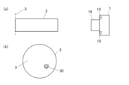
本実施形態の撮像装置1は、図2(a)に示すように、被写体3に当接させた円筒状の筒2を通して被写体3の表面を撮像することができる。図2(b)に示すように、筒2の開口内に被写体3の所望の箇所(指定部分30)が入るように筒2を配置し、筒2及び被写体3が撮像装置1の画角に入るように、撮像装置1をスタンド(図示せず)に固定し、さらに被写体3を発光部15で照明した状態で、撮像を行う。これにより、筒2の入口から出口までの間が遮蔽物により遮蔽されるのを抑制しつつ、指定部分30を確実に撮像することができる。この方法は、例えば、子宮頸部といった身体の奥部を撮像する場合等に好適に用いることができ、その場合、筒2は膣に挿入される膣鏡である。指定部分30は、例えば診察対象の患部(鼻腔、耳腔など)であってもよく、あるいは、構造物の穴の底部でもよい。撮像時には、発光部15から筒2の内部に光が照射されて、被写体3の指定部分30を含む表面が照明される。撮像装置1と筒2との位置関係を固定するためのアダプターが用いられてもよい。
<Operation of imaging device>
Next, the operation of the
FIG. 2 is a diagram illustrating an example of an imaging method using the
The
図3は、撮像が行われるときの撮像装置1の背面を示す図である。
撮像装置1の背面(撮像時に被写体3に向ける側とは反対側の面)には、表示部16の表示画面161、及び複数の操作ボタン172が設けられている。
FIG. 3 is a diagram showing the back side of the
A
表示画面161は、被写体のスルー画が表示される矩形の表示領域161a、及び操作アイコンが配列された操作アイコン領域161bを含む。スルー画は、撮像部14により所定のフレームレートで撮像された被写体画像の画像データをリアルタイムで動画表示させたものである。よって、スルー画には、被写体3のうち撮像部14による撮像の画角に対応する範囲が表示される。ユーザから撮像が指示されると、スルー画の画角で撮像が行われる。表示領域161aには、被写体のうちピントを合わせる対象の位置を表すフォーカスマーク161cが表示される。フォーカスマーク161cは、ここでは矩形の領域を表すマークであるが、これに限定されない。161aにおけるフォーカスマーク161cの中心位置を、以下ではフォーカス位置Pfと記す。
The
操作アイコン領域161bには、撮像アイコン161dを始めとする種々の操作アイコンが表示されている。操作アイコンの位置に対する接触操作がなされると、接触位置の操作アイコンに予め対応付けられた処理がCPU11により実行される。例えば、撮像アイコン161dの位置に対する接触操作がなされると、CPU11は、その時点におけるスルー画の構図で撮像部14により被写体を撮像させる。このときの撮像解像度は、スルー画の表示のために表示部16に送信される画像データの解像度より高くてもよい。静止画の撮像の他、動作モードに応じて動画の撮像が可能であってもよい。
Various operation icons including an
操作ボタン172には、スルー画を拡大表示(ズームイン)させるための拡大ボタン172a、スルー画を縮小表示(ズームアウト)させるための縮小ボタン172b、撮像装置1の動作モードを変更するためのモード変更ボタン172c、及び撮像済の画像を表示領域161aに表示させるための再生ボタン172dなどがある。
The
拡大ボタン172aが操作(例えば、押下)されると、表示領域161aにおけるスルー画が拡大される。以下では、拡大前の等倍のスルー画を被写体画像40と記す。拡大ボタン172aによる拡大対象の被写体画像40は、撮像装置1と被写体3との相対位置が一定となるように固定されることで静止している画像であってもよい。あるいは、被写体画像40は、所定のユーザ操作に応じてスルー画を静止させた静止画であってもよい。拡大ボタン172aに対するユーザ操作が、「第2のユーザ操作」に相当する。
When the enlarge
本実施形態では、被写体画像40の拡大は、デジタルズームにより行われる。すなわち、被写体画像40の拡大は、被写体画像40の画像データの一部を拡大後の表示対象範囲として抽出して、表示領域161aに合わせて拡大表示することにより行われる。筒越しに被写体3を照明して撮像装置1を固定した状態で撮像する方法では、光学ズームを用いると被写体3が画角に入らなくなるためである。拡大ボタン172aを操作するごとに、被写体画像40の拡大率(以下、倍率又は表示倍率とも記す)が所定の値に増大し、最大倍率に達すると、以降は拡大ボタン172aを操作しても被写体画像40は拡大されない。例えば、拡大ボタン172aを操作するごとに、ある増大値で増大された倍率で拡大(例えば増大値=0.1、すなわち1.1倍、1.2倍・・・と拡大)され、最大倍率(本実施形態では、8倍)まで倍率が増大していく。
In this embodiment, the
被写体画像40が任意の倍率で拡大されている状態で縮小ボタン172bが操作されると、上記の拡大動作とは逆に、被写体画像40の倍率が低減して、表示が縮小される(ある減少値で減少された倍率で縮小(例えば減少値=0.1、すなわち7.9倍、7.8倍・・・1倍と縮小)される)。縮小ボタン172bに対するユーザ操作が、「第3のユーザ操作」に相当する。縮小ボタン172bが操作されるごとに上記の拡大動作と同一の倍率ステップで倍率が低減し、等倍に達すると、以降は縮小ボタン172bを操作しても被写体画像40は縮小されない。
When the
拡大ボタン172a及び縮小ボタン172bにより被写体画像40の表示倍率が調整された状態で撮像アイコン161dが操作されると、表示領域161aに表示されている倍率(画角)で被写体3が撮像される。
When the
フォーカス位置Pfが表示領域161aの中心点にある場合に拡大ボタン172aが操作されると、この中心点の位置を基準として被写体画像40が拡大される。よって、図3に例示されているように、被写体画像40のうち撮像したい指定部分30が表示領域161aの中心点(画角の中心)から外れていると、表示倍率の増大に応じて指定部分30が中心点から遠くなり、ある表示倍率以降では表示領域161aに表示されなくなってしまう。
When the enlarge
これに対し、図4に示すように、表示領域161aの中心点に指定部分30が位置するように筒2に対する撮像装置1の位置を調整すると、画角に筒2の外部領域が入ってしまう場合がある。この状態では、発光部15からの照明光の一部が筒2の外部に照射されるため、筒2の内部の被写体3に対する照明が不十分となる問題がある。
On the other hand, as shown in FIG. 4, if the position of the
そこで、本実施形態の撮像装置1では、図3に示すように表示領域161aの中心点から外れた位置に指定部分30がある場合に、指定部分30と、拡大前の初期の画角における複数の縁部のうち指定部分30に最も近い縁部とが表示領域161aの内部に収まり続ける態様で被写体画像40を拡大することが可能となっている。詳しくは、図5に示すように、指定部分30を指定する所定のユーザ操作(第1のユーザ操作)が行われると、被写体画像40のうち指定部分30の代表点Prに対応する位置にフォーカス位置Pfが設定され、当該フォーカス位置Pfが中心となるようにフォーカスマーク161cが移動する。指定部分30を指定するユーザ操作は、例えば表示領域161aのうち指定部分30を指でタップする操作であってもよい。この操作により特定された位置が、指定部分30の代表点Prとされる。このように、第1のユーザ操作により指定された指定部分30をCPU11が取得する動作は、指定部分30の代表点Prを特定する処理を含んでいてもよい。また、当該動作は、代表点Prから所定の画素範囲内を指定部分30として特定する処理を含んでいてもよい。図5に示す状態で拡大ボタン172aが操作されると、指定部分30と、上記の最も近い縁部とが表示領域161aの内部に収まるように被写体画像40が拡大され、指定部分30の代表点Prが表示領域161aの中心点に近付く。代表点Prが中心点に到達した後は、図6に示すように、中心点を中心に、指定部分30が表示領域161aの内部に収まったまま被写体画像40が拡大される。このように、拡大後の表示対象範囲40Eに指定部分30が入るように、被写体画像40から表示対象範囲40Eが抽出されて表示領域161aに表示される。なお、図3、5、6において代表点Pr及びフォーカス位置Pfを示す黒点は、説明の便宜上示したものであり、実際の表示領域161aには表示されない。
以下では、このように被写体画像40を拡大表示させる動作について詳しく説明する。
Therefore, in the
The operation of enlarging and displaying the
<被写体画像の拡大表示動作>
図7は、被写体画像40の拡大表示動作を説明する図である。
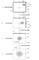
図7のA~Dは、被写体画像40から抽出された表示対象範囲が表示領域161aに表示されている状態を示す。以下では、表示領域161aに表示されている表示対象範囲において、表示領域161aの中心点に対応する点を原点Oとするxy座標系により、表示対象範囲内の位置を表す。原点Oを通り、表示対象範囲がなす矩形(したがって、表示領域161aがなす矩形)の長辺に平行な軸をx軸(第1軸)とし、原点Oを通りx軸に垂直な軸をy軸(第2軸)とする。以下の説明における上方向、下方向、左方向、右方向は、図7(図9、図16、図17も同様)における上下左右の各方向を指すものとする。図7における上方向が+y方向、下方向が-y方向、右方向が+x方向、左方向が-x方向である。被写体画像40の拡大表示動作は、表示対象範囲(表示領域161a)を第1~第4象限に分けたときに、指定部分30の代表点Pr及びフォーカス位置Pfがいずれの象限にあるかによって異なる。図7では、フォーカス位置Pfが第1象限にある場合が例示されている。ここで、第1象限は、xy座標系におけるx>0、y>0の部分であり、第2象限は、x<0、y>0の部分であり、第3象限は、x<0、y<0の部分であり、第4象限は、x>0、y<0の部分である。
<Subject image enlargement display operation>
FIG. 7 is a diagram illustrating the operation of enlarging and displaying the
A to D in FIG. 7 show a state in which the display target range extracted from the
図7のAは、等倍の被写体画像40が表示領域161aに表示されている状態を示す。すなわち、図7のAは、被写体画像40の全体が表示対象範囲として抽出されて表示されている状態を示す。このように、表示対象範囲は、被写体画像40の全体であってもよい。図7のAでは、被写体画像40の上辺S1、右辺S2、下辺S3及び左辺S4が、表示領域161aの外周に位置している。図7のAの状態において拡大ボタン172aが1回又は複数回操作されると、操作されるごとに第1の拡大表示制御が行われて、図7のBに示す第1の拡大画像が表示領域161aに表示される。図7のBの状態において拡大ボタン172aが1回又は複数回操作されると、操作されるごとに第2の拡大表示制御が行われて、図7のCに示す第2の拡大画像が表示領域161aに表示される。図7のCの状態において拡大ボタン172aが1回又は複数回操作されると、操作されるごとに第3の拡大表示制御が行われて、図7のDに示す第3の拡大画像が表示領域161aに表示される。拡大ボタン172aの操作回数等に応じて、図7のAとBの中間の表示倍率の第1の拡大画像が表示されてもよい。同様に、図7のBとCの中間の表示倍率の第2の拡大画像が表示されてもよく、図7のCとDの中間の表示倍率の第3の拡大画像が表示されてもよい。以下、第1~第3の拡大表示制御について説明する。
A in FIG. 7 shows a state in which the same-size
第1の拡大表示制御では、図7のAに示す被写体画像40の4つの角部のうち、指定部分30の代表点Prから最も近い角部に拡大基準点P1(拡大基準部分)が設定される。例えば、等倍の被写体画像40が表示領域161aに表示されている状態で代表点Pr及びフォーカス位置Pfが表示領域161aの第1象限にある場合には、被写体画像40の縁部のうち、上辺S1及び右辺S2が交差する右上の角部に拡大基準点P1が設定される。そして、被写体画像40の拡大後の表示対象範囲40aに拡大基準点P1及び指定部分30が収まるように、被写体画像40から拡大後に表示される表示対象範囲40aが抽出されて、抽出された表示対象範囲40aが表示領域161aに拡大表示される(図7のB)。別の観点では、拡大基準点P1を基準に被写体画像40が拡大されて表示される。ここで、「拡大基準点を基準に拡大して表示する」とは、拡大前後において、表示領域161aにおける拡大基準点の位置が同一である態様で拡大することをいう。拡大基準点P1を基準に拡大することで、拡大後の指定部分30の代表点Prは、表示領域161aの中心点(拡大後の表示対象範囲の原点O)に近付く。言い換えると、第1の拡大表示制御では、拡大後における指定部分30の代表点Prと表示領域161aの中心点(原点O)との距離が、拡大前における代表点Prと中心点(原点O)との距離以下となるように拡大基準点P1が設定される。これにより、拡大後に指定部分30が表示領域161aから外れない(見切られない)ようにすることができる。また、フォーカス位置Pfは、表示領域161aのうち、拡大後の表示対象範囲40aにおける代表点Prが表示される位置に変更される。
In the first enlargement display control, an enlargement reference point P1 (enlargement reference portion) is set at the corner closest to the representative point Pr of the designated
図7のAの状態から第1の拡大表示制御により表示倍率がある値に達すると、図7のBに示すように、拡大後の表示対象範囲40aにおける指定部分30の代表点Pr及びフォーカス位置Pfが、y軸に重なる。なお、第1の拡大表示制御の終了時に代表点Pr及びフォーカス位置Pfがx<0となる領域内(すなわち、y軸より左側の領域内)に位置することとなる場合には、代表点Pr及びフォーカス位置Pfがy軸に重なるように拡大後の表示対象範囲40aが調整される。また、等倍の被写体画像40において代表点Prがy軸より左側の象限(第2象限又は第3象限)に位置する場合には、代表点Prは、第1の拡大制御によりy軸の左側からy軸に近付く。この場合において、第1の拡大表示制御の終了時に代表点Pr及びフォーカス位置Pfがx>0となる領域内(すなわち、y軸より右側の領域内)に位置することとなる場合には、代表点Pr及びフォーカス位置Pfがy軸に重なるように拡大後の表示対象範囲40aが調整される。第1の拡大表示制御において代表点Pr及びフォーカス位置Pfがy軸に重なった場合には、第2の拡大表示制御が開始される。
When the display magnification reaches a certain value by the first enlargement display control from the state of A in FIG. 7, the representative point Pr and the focus position of the designated
第2の拡大表示制御では、代表点Pr及びフォーカス位置Pfが重なったy軸と、被写体画像40の縁部との交点に拡大基準点P2(拡大基準部分)が設定される。詳しくは、図7のBの状態では、表示領域161aの外周のうち上辺に、被写体画像40の縁部の上辺S1が重なっており、y軸は、この上辺S1と交差している。よって、y軸と、被写体画像40の縁部の上辺S1との交点に拡大基準点P2が設定される。このように設定された拡大基準点P2は、被写体画像40の縁部上に位置する。そして、拡大基準点P2及び指定部分30が収まるように、被写体画像40から(表示対象範囲40aから)拡大後の表示対象範囲40bが抽出されて表示される。すなわち、拡大基準点P2を基準に被写体画像40が拡大されて表示される。拡大基準点P2を基準に拡大することで、指定部分30の代表点Prのx軸方向の位置が固定された状態で、代表点Prが表示領域161aの中心点(原点O)に近付く。したがって、第2の拡大表示制御においても、拡大後における代表点Prと中心点(原点O)との距離が、拡大前における代表点Prと中心点(原点O)との距離以下となるように拡大基準点P2が設定される。
In the second enlarged display control, an enlarged reference point P2 (enlarged reference portion) is set at the intersection of the y-axis where the representative point Pr and the focus position Pf overlap and the edge of the
図7のBの状態から第2の拡大表示制御により被写体画像40の表示倍率がある値に達すると、図7のCに示すように、拡大後の表示対象範囲40bにおける指定部分30の代表点Pr及びフォーカス位置Pfが、表示領域161aの中心点(原点O)に一致する。なお、第2の拡大表示制御の終了時に代表点Pr及びフォーカス位置Pfがy<0となる領域内(すなわち、x軸より下側の領域内)に位置することとなる場合には、代表点Pr及びフォーカス位置Pfが中心点(原点O)に一致するように拡大後の表示対象範囲40bが調整される。また、等倍の被写体画像40において代表点Prがx軸より下側の象限(第3象限又は第4象限)に位置する場合には、代表点Prは、第2の拡大制御によりx軸の下側からx軸に近付くことがある。この場合において、第2の拡大表示制御の終了時に代表点Pr及びフォーカス位置Pfがy>0となる領域内(すなわち、x軸より上側の領域内)に位置することとなる場合には、代表点Pr及びフォーカス位置Pfがx軸に重なるように拡大後の表示対象範囲40bが調整される。第2の拡大表示制御において代表点Pr及びフォーカス位置Pfが表示領域161aの中心点(原点O)に一致した場合には、第3の拡大表示制御が開始される。
When the display magnification of the
第3の拡大表示制御では、被写体画像40のうち、この時点で表示領域161aの中心点(原点O)に位置する点、すなわち代表点Prに拡大基準点P3(拡大基準部分)が設定され、当該代表点Prが中央(例えば、中心)に位置するように拡大後の表示対象範囲40cが抽出されて拡大表示される。この結果、指定部分30の代表点Prが表示領域161aの中央(例えば、中心点(原点O))に固定された状態で被写体画像40をさらに拡大した第3の拡大画像が表示される。これにより、所望の指定部分30を画角の中心で拡大して観察することができる。
In the third enlargement display control, an enlargement reference point P3 (enlargement reference portion) is set at a point located at the center point (origin O) of the
図8は、拡大前の等倍における被写体画像40の第1象限に指定部分30の代表点Prがある場合に被写体画像40から抽出される表示対象範囲の観点で、第1~第3の拡大表示制御を説明する図である。
図8における複数の矩形は、拡大ボタン172aが操作されるごとに被写体画像40から抽出される表示対象範囲40a~40cを表している。第1の拡大表示制御では、波線付きの矢印A1に示すように、右上の角部に設定された拡大基準点P1を共通して含み、かつ大きさが徐々に小さくなるように、表示対象範囲40aが抽出される。表示対象範囲40aが代表点Prを中心に左右対称となると、第2の拡大表示制御が開始される。第2の拡大表示制御では、波線付きの矢印A2に示すように、表示対象範囲40bの上辺の中央に設定された拡大基準点P2を共通して含み、かつ大きさが徐々に小さくなるように、表示対象範囲40bが抽出される。表示対象範囲40bが代表点Prを中心に上下対称となると、第3の拡大表示制御が開始される。第3の拡大表示制御では、波線付きの矢印A3に示すように、代表点Prに設定された拡大基準点P3を中心として、大きさが徐々に小さくなるように表示対象範囲40cが抽出される。
FIG. 8 shows the first to third enlargements from the viewpoint of the display target range extracted from the
A plurality of rectangles in FIG. 8 represent display target ranges 40a to 40c extracted from the
図9は、代表点Pr及びフォーカス位置Pfが第1象限にある場合の被写体画像40の拡大表示動作の他の例を説明する図である。
図9に示す例では、第1の拡大表示制御により表示倍率がある値に達すると、図9のBに示すように、拡大後の表示対象範囲40aにおける指定部分30の代表点Pr及びフォーカス位置Pfが、x軸に重なる。なお、第1の拡大表示制御の終了時に代表点Pr及びフォーカス位置Pfがy<0となる領域内(すなわち、x軸より下側の領域内)に位置することとなる場合には、代表点Pr及びフォーカス位置Pfがx軸に重なるように拡大後の表示対象範囲40aが調整される。また、等倍の被写体画像40において代表点Prがx軸より下側の象限(第3象限又は第4象限)に位置する場合には、代表点Prは、第1の拡大制御によりx軸の下側からx軸に近付く。この場合において、第1の拡大表示制御の終了時に代表点Pr及びフォーカス位置Pfがy>0となる領域内(すなわち、x軸より上側の領域内)に位置することとなる場合には、代表点Pr及びフォーカス位置Pfがx軸に重なるように拡大後の表示対象範囲40aが調整される。第1の拡大表示制御において代表点Pr及びフォーカス位置Pfがx軸に重なった場合には、第2の拡大表示制御が開始される。
FIG. 9 is a diagram illustrating another example of the enlarged display operation of the
In the example shown in FIG. 9, when the display magnification reaches a certain value by the first enlargement display control, as shown in B of FIG. Pf overlaps the x-axis. Note that if the representative point Pr and the focus position Pf are located within the region where y<0 (that is, within the region below the x-axis) at the end of the first enlarged display control, the representative point Pr and the focus position Pf are The enlarged
第2の拡大表示制御では、x軸及びy軸のうち代表点Prが重なった一方(図9のBではx軸)と、被写体画像40の縁部との交点に拡大基準点P2が設定される。詳しくは、図9のBの状態では、表示領域161aの外周のうち右辺に、被写体画像40の縁部の右辺S2が重なっている。よって、x軸と、この右辺S2との交点に拡大基準点P2が設定される。このように設定された拡大基準点P2は、被写体画像40の縁部上に位置する。そして、拡大基準点P2及び指定部分30が収まるように、被写体画像40から(表示対象範囲40aから)拡大後の表示対象範囲40bが抽出されて表示される。すなわち、拡大基準点P2を基準に被写体画像40が拡大されて表示される。拡大基準点P2を基準に拡大することで、指定部分30の代表点Prのy軸方向の位置が固定された状態で、代表点Prが表示領域161aの中心点(原点O)に近付く。
In the second enlargement display control, an enlargement reference point P2 is set at the intersection of one of the x-axis and y-axis where the representative point Pr overlaps (the x-axis in B in FIG. 9) and the edge of the
図9のBの状態から第2の拡大表示制御により被写体画像40の表示倍率がある値に達すると、図9のCに示すように、拡大後の表示対象範囲40bにおける指定部分30の代表点Pr及びフォーカス位置Pfが、表示領域161aの中心点(原点O)に一致する。なお、第2の拡大表示制御の終了時に代表点Pr及びフォーカス位置Pfがx<0となる領域内(すなわち、y軸より左側の領域内)に位置することとなる場合には、代表点Pr及びフォーカス位置Pfが表示領域161aの中心点(原点O)に一致するように拡大後の表示対象範囲40bが調整される。また、等倍の被写体画像40において代表点Prがy軸より左側の象限(第2象限又は第3象限)に位置する場合には、代表点Prは、第2の拡大制御によりy軸の左側からy軸に近付くことがある。この場合において、第2の拡大表示制御の終了時に代表点Pr及びフォーカス位置Pfがx>0となる領域内(すなわち、x軸より右側の領域内)に位置することとなる場合には、代表点Pr及びフォーカス位置Pfがy軸に重なるように拡大後の表示対象範囲40bが調整される。第2の拡大表示制御において代表点Pr及びフォーカス位置Pfが表示領域161aの中心点(原点O)に一致した場合には、第3の拡大表示制御が開始される。以降の第3の拡大表示制御は、図7と同一である。
When the display magnification of the
等倍の被写体画像40において代表点Pr及びフォーカス位置Pfが第2~第4象限にある場合の動作は、図7又は図9の動作をx軸及び/又はy軸を中心に反転させたものに相当する。
例えば、代表点Pr及びフォーカス位置Pfが第2象限にある場合の動作は、図7又は図9を、y軸を中心に反転させたものに相当する。この場合には、第1の拡大表示制御では、被写体画像40の縁部のうち、上辺S1及び左辺S4が交差する左上の角部に拡大基準点P1が設定される。また、第1の拡大表示制御において代表点Pr及びフォーカス位置Pfがy軸のうちy>0の部分に重なった場合には、第2の拡大表示制御では、被写体画像40の縁部の上辺S1とy軸との交点に拡大基準点P2が設定される。第1の拡大表示制御において代表点Pr及びフォーカス位置Pfがx軸のうちx<0の部分に重なった場合には、第2の拡大表示制御では、被写体画像40の縁部の左辺S4とx軸との交点に拡大基準点P2が設定される。
The operation when the representative point Pr and the focus position Pf are in the second to fourth quadrants in the same-
For example, the operation when the representative point Pr and the focus position Pf are in the second quadrant corresponds to FIG. 7 or FIG. 9 inverted around the y-axis. In this case, in the first enlargement display control, the enlargement reference point P1 is set at the upper left corner of the edge of the
また、代表点Pr及びフォーカス位置Pfが第3象限にある場合の動作は、図7又は図9を、x軸及びy軸を中心に反転させたものに相当する。この場合には、第1の拡大表示制御では、被写体画像40の縁部のうち、下辺S3及び左辺S4が交差する左下の角部に拡大基準点P1が設定される。また、第1の拡大表示制御において代表点Pr及びフォーカス位置Pfがy軸のうちy<0の部分に重なった場合には、第2の拡大表示制御では、被写体画像40の縁部の下辺S3とy軸との交点に拡大基準点P2が設定される。第1の拡大表示制御において代表点Pr及びフォーカス位置Pfがx軸のうちx<0の部分に重なった場合には、第2の拡大表示制御では、被写体画像40の縁部の左辺S4とx軸との交点に拡大基準点P2が設定される。
Further, the operation when the representative point Pr and the focus position Pf are in the third quadrant corresponds to FIG. 7 or FIG. 9 inverted around the x-axis and the y-axis. In this case, in the first enlargement display control, the enlargement reference point P1 is set at the lower left corner of the edge of the
また、代表点Pr及びフォーカス位置Pfが第4象限にある場合の動作は、図7又は図9を、x軸を中心に反転させたものに相当する。この場合には、第1の拡大表示制御では、被写体画像40の縁部のうち、右辺S2及び下辺S3が交差する右下の角部に拡大基準点P1が設定される。また、第1の拡大表示制御において代表点Pr及びフォーカス位置Pfがy軸のうちy<0の部分に重なった場合には、第2の拡大表示制御では、被写体画像40の縁部の下辺S3とy軸との交点に拡大基準点P2が設定される。第1の拡大表示制御において代表点Pr及びフォーカス位置Pfがx軸のうちx>0の部分に重なった場合には、第2の拡大表示制御では、被写体画像40の縁部の右辺S2とx軸との交点に拡大基準点P2が設定される。
Furthermore, the operation when the representative point Pr and the focus position Pf are in the fourth quadrant corresponds to FIG. 7 or FIG. 9 inverted around the x-axis. In this case, in the first enlargement display control, the enlargement reference point P1 is set at the lower right corner of the edge of the
また、等倍の被写体画像40を表示領域161aに表示させたときに代表点Pr及びフォーカス位置Pfがx軸上又はy軸上に位置し、表示領域161aの中心点(原点O)に一致しない場合には、第1の拡大表示制御が省略され、第2の拡大表示制御及び第3の拡大表示制御が順に実行される。また、等倍の被写体画像40を表示領域161aに表示させたときに代表点Pr及びフォーカス位置Pfが表示領域161aの中心点(原点O)に位置する場合には、第1の拡大表示制御及び第2の拡大表示制御が省略され、第3の拡大表示制御が実行される。
Furthermore, when the same size
次に、第1~第3の拡大表示制御を行うための拡大表示処理の制御手順について説明する。
図10及び図11は、拡大表示処理のCPU11による制御手順を示すフローチャートである。
拡大表示処理が開始されると、CPU11は、撮像部14から受信した画像データに基づいて、等倍の被写体画像40を表示領域161aに表示させる(ステップS101)。
Next, a control procedure for the enlarged display processing for performing the first to third enlarged display controls will be described.
FIGS. 10 and 11 are flowcharts showing the control procedure by the
When the enlarged display process is started, the
CPU11は、指定部分30を指定する操作が検出されたか否かを判別する(ステップS102)。ここでは、CPU11は、タッチパネル171のうち表示領域161aに対する接触操作がなされた場合に、指定部分30を指定する操作が検出されたと判別する。当該操作が検出されていないと判別された場合には(ステップS102で“NO”)、CPU11は、再度ステップS102を実行する。当該操作が検出されたと判別された場合には(ステップS102で“YES”)、CPU11は、被写体画像40のうち接触操作がなされた点に相当する点を、指定部分30の代表点Prとして取得し、フォーカス位置Pfを表示領域161a上の代表点Prの位置に設定する(ステップS103)。これに応じて、CPU11は、表示領域161aにおいて、フォーカス位置Pfを中心とするフォーカスマーク161cを表示させる。
The
ステップS103が終了すると、CPU11は、拡大ボタン172aに対する操作を検出したか否かを判別し(ステップS104)、当該操作を検出していないと判別された場合には(ステップS104で“NO”)、再度ステップS104を実行する。当該操作を検出したと判別された場合には(ステップS104で“YES”)、CPU11は、当該操作に応じた拡大率を取得する(ステップS105)。すなわち、CPU11は、ステップS104の実行前における拡大率に所定の増大値(例えば、0.1)を加算し、上記操作に応じた拡大率とする。また、CPU11は、代表点Prが被写体画像40の第1範囲R1内にあるか否かを判別する(ステップS106)。
When step S103 ends, the
図12は、第1範囲R1を示す図である。
第1範囲R1は、被写体画像40と相似形の矩形の範囲である。第1範囲R1の中心は、被写体画像40の中心Cと一致している。第1範囲R1の大きさは、ステップS105において取得した拡大率に応じて調整される。詳しくは、第1範囲R1の大きさは、表示対象範囲を、取得した拡大率に応じて、かつ、指定部分30の代表点Prが表示対象範囲の中心(原点O)に位置するように、被写体画像40から抽出すると仮定した場合における当該表示対象範囲の中心が第1範囲R1の範囲内に位置するように調整される。言い換えると、第1範囲R1は、取得した拡大率の表示対象範囲のx方向について幅の1/2を長さL1、当該表示対象範囲のy方向についての幅の1/2を長さL2とした場合に、被写体画像40の右辺S2及び左辺S4のそれぞれからの距離が長さL1であり、被写体画像40の上辺S1及び下辺S3のそれぞれからの距離が長さL2である矩形とされる。よって、第1範囲R1は、拡大率が大きいほど、より大きく設定される。代表点Prが第1範囲R1内にある場合には、図12に示すように、取得した拡大率で、代表点Prを原点Oとする拡大後の表示対象範囲40cを抽出することができる。よって、代表点Prに拡大基準点P3が設定されて第3の拡大表示制御が行われる。なお、第1範囲R1の大きさは、表示対象範囲を、取得した拡大率に応じて、かつ、指定部分30の代表点Prが表示対象範囲の中央(中心近傍の所定範囲内)に位置するように、被写体画像40から抽出すると仮定した場合における当該表示対象範囲の中央が第1範囲R1の範囲内に位置するように調整されてもよい。
FIG. 12 is a diagram showing the first range R1.
The first range R1 is a rectangular range similar to the
図10に戻り、代表点Prが被写体画像40の第1範囲R1内にあると判別された場合には(ステップS106で“YES”)、CPU11は、第3の拡大表示制御を実行する。すなわち、CPU11は、代表点Prに拡大基準点P3を設定し(ステップS109)、拡大基準点P3を基準に、拡大後の表示対象範囲40cを抽出して表示領域161aに表示させる(ステップS110)。
Returning to FIG. 10, if it is determined that the representative point Pr is within the first range R1 of the subject image 40 ("YES" in step S106), the
代表点Prが被写体画像40の第1範囲R1内にないと判別された場合には(ステップS106で“NO”)、CPU11は、代表点Prが被写体画像40の第2範囲R2内にあるか否かを判別する(ステップS107)。
If it is determined that the representative point Pr is not within the first range R1 of the subject image 40 (“NO” in step S106), the
図13は、第2範囲R2を示す図である。
第2範囲R2は、被写体画像40のうち、第1範囲R1よりも上側(+y方向側、第2方向について一方側)及び下側(-y方向側、第2方向について他方側)の部分にそれぞれ相当する矩形の範囲である。第1範囲R1よりも上側に位置する第2範囲R2は、第1範囲R1の上辺に接する下辺と、被写体画像40の上辺S1とを含み、左右方向(x方向、第1方向)の幅が第1範囲R1と等しい矩形の範囲である。第1範囲R1よりも下側に位置する第2範囲R2は、第1範囲R1の下辺に接する上辺と、被写体画像40の下辺S3とを含み、左右方向(x方向)の幅が第1範囲R1と等しい矩形の範囲である。第2範囲R2の大きさは、第1範囲R1の大きさの調整に連動して調整される。よって、第2範囲R2の左右方向の幅は、ステップS105において取得した拡大率が大きいほど、より大きく設定され、上下方向の幅は、取得した拡大率が大きいほど、より小さく設定される。代表点Prが上側の第2範囲R2内にある場合には、図13に示すように、取得した拡大率で、代表点Prがy軸上のうちy>0の範囲に位置し、かつ上辺が被写体画像40の上辺S1に重なるような表示対象範囲40bを抽出することができる。また、代表点Prが下側の第2範囲R2内にある場合には、取得した拡大率で、代表点Prがy軸上のうちy<0の範囲に位置し、かつ下辺が被写体画像40の下辺S3に重なるような表示対象範囲40bを抽出することができる。このような表示対象範囲40bを抽出するために、代表点Prが第2範囲R2内にある場合は、被写体画像40の上辺S1上及び下辺S3上のいずれかに位置し、かつ代表点Prからの距離が最短である点(上記のy軸と被写体画像40の縁部との交点に相当)に拡大基準点P2が設定されて、第2の拡大表示制御が行われる。
FIG. 13 is a diagram showing the second range R2.
The second range R2 is a portion of the
図10に戻り、代表点Prが被写体画像40の第2範囲R2内にあると判別された場合には(ステップS107で“YES”)、CPU11は、第2の拡大表示制御を実行する。すなわち、CPU11は、まず、被写体画像40の上辺S1上及び下辺S3上のいずれかに位置し、かつ代表点Prからの距離が最短である点(抽出後の表示対象範囲40bにおけるy軸と被写体画像40の縁部との交点に相当)に、拡大基準点P2を設定する(図11のステップS111)。詳しくは、代表点Prが上側の第2範囲R2内にある場合には、被写体画像40の上辺S1に拡大基準点P2を設定し、代表点Prが下側の第2範囲R2内にある場合には、被写体画像40の下辺S3に拡大基準点P2を設定する。
Returning to FIG. 10, if it is determined that the representative point Pr is within the second range R2 of the subject image 40 ("YES" in step S107), the
CPU11は、拡大基準点P2を基準に拡大後の表示対象範囲40bを抽出する(ステップS112)。また、CPU11は、表示領域161aのうち、拡大後の表示対象範囲40bにおける代表点Prの表示位置に、フォーカス位置Pfを再設定する。
The
CPU11は、抽出した表示対象範囲40bを拡大して、表示領域161aに表示させる(ステップS113)。また、CPU11は、設定したフォーカス位置Pfにフォーカスマーク161cを表示させる。
The
図10のステップS107において、代表点Prが被写体画像40の第2範囲R2内にないと判別された場合には(ステップS107で“NO”)、CPU11は、代表点Prが被写体画像40の第3範囲R3内にあるか否かを判別する(ステップS108)。
In step S107 of FIG. 10, if it is determined that the representative point Pr is not within the second range R2 of the subject image 40 (“NO” in step S107), the
図14は、第3範囲R3を示す図である。
第3範囲R3は、被写体画像40のうち、第1範囲R1よりも右側(+x方向側、第1方向について一方側)及び左側(-x方向側、第1方向について他方側)の部分にそれぞれ相当する矩形の範囲である。第1範囲R1よりも右側に位置する第3範囲R3は、第1範囲R1の右辺に接する左辺と、被写体画像40の右辺S2とを含み、上下方向(y方向、第2方向)の幅が第1範囲R1と等しい矩形である。第1範囲R1よりも左側に位置する第3範囲R3は、第1範囲R1の左辺に接する右辺と、被写体画像40の左辺S4とを含み、上下方向(y方向)の幅が第1範囲R1と等しい矩形である。第3範囲R3の大きさは、第1範囲R1の大きさの調整に連動して調整される。よって、第3範囲R3の上下方向の幅は、ステップS105において取得した拡大率が大きいほど、より大きく設定され、左右方向の幅は、取得した拡大率が大きいほど、より小さく設定される。代表点Prが右側の第3範囲R3内にある場合には、図14に示すように、取得した拡大率で、代表点Prがx軸上のうちx>0の範囲に位置し、かつ右辺が被写体画像40の右辺S2に重なるような表示対象範囲40bを抽出することができる。また、代表点Prが左側の第3範囲R3内にある場合には、取得した拡大率で、代表点Prがx軸上のうちx<0の範囲に位置し、かつ左辺が被写体画像40の左辺S4に重なるような表示対象範囲40bを抽出することができる。このような表示対象範囲40bを抽出するために、代表点Prが第3範囲R3内にある場合は、被写体画像40の右辺S2上及び左辺S4上のいずれかに位置し、かつ代表点Prからの距離が最短である点(上記のx軸と被写体画像40の縁部との交点に相当)に拡大基準点P2が設定されて、第2の拡大表示制御が行われる。
FIG. 14 is a diagram showing the third range R3.
The third range R3 is located on the right side (the +x direction side, one side in the first direction) and the left side (the -x direction side, the other side in the first direction) of the first range R1 in the
図10に戻り、代表点Prが被写体画像40の第3範囲R3内にあると判別された場合には(ステップS108で“YES”)、CPU11は、第2の拡大表示制御を実行する。すなわち、CPU11は、まず、被写体画像40の右辺S2上及び左辺S4上のいずれかに位置し、かつ代表点Prからの距離が最短である点(抽出後の表示対象範囲40bにおけるx軸と被写体画像40の縁部との交点に相当)に、拡大基準点P2を設定する(図11のステップS114)。詳しくは、代表点Prが右側の第3範囲R3内にある場合には、被写体画像40の右辺S2に拡大基準点P2を設定し、代表点Prが左側の第3範囲R3内にある場合には、被写体画像40の左辺S4に拡大基準点P2を設定する。
Returning to FIG. 10, if it is determined that the representative point Pr is within the third range R3 of the subject image 40 ("YES" in step S108), the
CPU11は、拡大基準点P2を基準に、拡大後の表示対象範囲40bを抽出する(ステップS115)。また、CPU11は、表示領域161aのうち、拡大後の表示対象範囲40bにおける代表点Prの表示位置に、フォーカス位置Pfを再設定する。
The
CPU11は、抽出した表示対象範囲40bを拡大して、表示領域161aに表示させる(ステップS116)。また、CPU11は、設定したフォーカス位置Pfにフォーカスマーク161cを表示させる。
The
図10のステップS108において、代表点Prが被写体画像40の第3範囲R3内にないと判別された場合には(ステップS108で“NO”)、代表点Prは、被写体画像40の第4範囲R4内にあると判別する。
In step S108 of FIG. 10, if it is determined that the representative point Pr is not within the third range R3 of the subject image 40 (“NO” in step S108), the representative point Pr is within the fourth range R3 of the
図15は、第4範囲R4を示す図である。
第4範囲R4は、被写体画像40のうち、第1範囲R1、第2範囲R2及び第3範囲R3を除いた範囲である。よって、第4範囲R4は、被写体画像40の4つの角部に対応する4箇所に位置する矩形の範囲である。第4範囲R4の大きさは、第1範囲R1の大きさの調整に連動して調整される。よって、第4範囲R4の上下方向及び左右方向の幅は、ステップS105において取得した拡大率が大きいほど、より小さく設定される。代表点Prが第4範囲R4内にある場合は、被写体画像40の4つの角部のうち代表点Prに最も近い角部に拡大基準点P1が設定されて、第1の拡大表示制御が行われる。
FIG. 15 is a diagram showing the fourth range R4.
The fourth range R4 is a range of the
図10に戻り、代表点Prが被写体画像40の第3範囲R3内にない(すなわち、第4範囲R4内にある)と判別された場合には(ステップS108で“NO”)、CPU11は、第1の拡大表示制御を実行する。すなわち、CPU11は、まず被写体画像40の4つの角部のうち、代表点Prに最も近い角部に拡大基準点P1を設定する(図11のステップS117)。詳しくは、代表点Prが右上の第4範囲R4内にある場合には、被写体画像40の右上の角部に拡大基準点P1が設定される(図15参照)。また、代表点Prが左上の第4範囲R4内にある場合には、被写体画像40の左上の角部に拡大基準点P1が設定される。また、代表点Prが左下の第4範囲R4内にある場合には、被写体画像40の左下の角部に拡大基準点P1が設定される。また、代表点Prが右下の第4範囲R4内にある場合には、被写体画像40の右下の角部に拡大基準点P1が設定される。
Returning to FIG. 10, if it is determined that the representative point Pr is not within the third range R3 of the subject image 40 (that is, within the fourth range R4) (“NO” in step S108), the
CPU11は、拡大基準点P1を基準に拡大後の表示対象範囲40aを抽出する(ステップS118)。また、CPU11は、表示領域161aのうち、拡大後の表示対象範囲40aにおける代表点Prの表示位置に、フォーカス位置Pfを再設定する。
The
CPU11は、抽出した表示対象範囲40aを拡大して、表示領域161aに表示させる(ステップS119)。また、CPU11は、設定したフォーカス位置Pfにフォーカスマーク161cを表示させる。
The
ステップS110、S113、S116及びS119のいずれかが終了すると、CPU11は、表示可能な最大倍率に達したか否かを判別する(ステップS120)。CPU11は、最大倍率に達していないと判別された場合には(ステップS120で“NO”)、処理を図10のステップS104に戻し、拡大ボタン172aに対する次の操作を受け付ける。最大倍率に達したと判別された場合には(ステップS120で“YES”)、CPU11は、拡大表示処理を終了させる。
When any one of steps S110, S113, S116, and S119 is completed, the
このように、CPU11は、取得された指定部分30の位置と取得された拡大率とに応じて、指定部分30をそれぞれ含む互いに異なる複数の表示対象範囲のいずれかを、被写体画像40から抽出し、抽出された表示対象範囲を拡大して表示領域161aに表示する。上記の拡大表示処理のステップS117~S119が第1の拡大表示制御に相当し、ステップS111~S113、及びステップS114~S116が第2の拡大表示制御に相当し、ステップS109及びS110が第3の拡大表示制御に相当する。また、ステップS103が「第1ステップ」に相当し、ステップS105~S120が「第2ステップ」に相当する。
In this way, the
<被写体画像の縮小表示動作>
次に、縮小ボタン172bに対する操作に応じて被写体画像40を縮小表示させる動作について説明する。
<Subject image reduction display operation>
Next, the operation of displaying the
図16は、被写体画像40の縮小表示動作の一例を説明する図である。
縮小表示動作は、上述の拡大表示動作によって被写体画像40の一部が拡大表示されているときに、縮小ボタン172bに対する操作がなされた場合に行われる。ここでは、図9のDに示した第3の拡大画像が表示されているときに縮小ボタン172bが操作される場合を例示する。
FIG. 16 is a diagram illustrating an example of a reduction display operation of the
The reduction display operation is performed when the
図16のAは、第3の拡大画像(表示対象範囲40c)が表示領域161aに表示されている状態を示す。図16のAの状態において縮小ボタン172bが1回又は複数回操作されると、操作されるごとに第1の縮小表示制御が行われて、図16のBに示す第2の拡大画像が表示領域161aに表示される。図16のBの状態において縮小ボタン172bが1回又は複数回操作されると、操作されるごとに第2の縮小表示制御が行われて、図16のCに示す第1の拡大画像が表示領域161aに表示される。図16のCの状態において縮小ボタン172bが1回又は複数回操作されると、操作されるごとに第3の縮小表示制御が行われて、図16のDに示す等倍の被写体画像40が表示領域161aに表示される。拡大ボタン172aの操作回数等に応じて、図16のAとBの中間の表示倍率の表示対象範囲40cが表示されてもよい。同様に、図16のBとCの中間の表示倍率の表示対象範囲40bが表示されてもよく、図16のCとDの中間の表示倍率の表示対象範囲40aが表示されてもよい。以下、第1~第3の縮小表示制御について説明する。
A in FIG. 16 shows a state in which the third enlarged image (
図16のAの表示領域161aには、フォーカス位置Pf及び代表点Prが表示領域161aの中心点(原点O)に重なっている状態の第3の拡大画像が表示されている。縮小ボタン172bの操作に応じて開始される第1の縮小表示制御では、被写体画像40のうち中心点(原点O)に相当する点、すなわち代表点Prに縮小基準点P4(縮小基準部分)が設定され、当該縮小基準点P4を基準に被写体画像40が縮小されて表示される。ここで、「縮小基準点を基準に縮小して表示する」とは、縮小前後において、表示領域161aにおける縮小基準点の位置が同一である態様で縮小することをいう。よって、縮小基準点P4が中心となるように縮小後の表示対象範囲が抽出されて縮小表示される。
In the
図16のAの状態から第1の縮小表示制御により被写体画像40の表示倍率がある値まで減少すると、図16のBに示すように、被写体画像40の縁部のうちいずれかの1辺が、表示領域161aの外周のうちいずれかの1辺と重なる。図16のBに示す例では、被写体画像40の縁部のうち上辺S1が、表示領域161aの外周の上辺と重なっている。このときの表示対象範囲は、図7のCに示した表示対象範囲40bに相当する。なお、縮小表示制御における表示倍率は一定の減少値で段階的に減少するため、代表点Prの位置によっては、抽出した表示対象範囲の1辺と、被写体画像40の縁部の1辺とが重なり得る表示倍率まで縮小されていても、当該1辺同士が重ならない場合がある。この場合には、表示対象範囲の1辺と、被写体画像40の縁部の1辺とが重なるように、表示倍率を微調整してもよい。あるいは、表示対象範囲の1辺と、被写体画像40の縁部の1辺とが重なるように、表示対象範囲の抽出範囲をずらす(平行移動させる)調整を行ってもよい。
When the display magnification of the
この状態で縮小ボタン172bに対する操作がなされると、第2の縮小表示制御が開始される。第2の縮小表示制御では、被写体画像40の縁部のうち表示領域161aの外周と重なった辺(ここでは、上辺S1)と、x軸又はy軸との交点(ここでは、y軸との交点)に相当する点に縮小基準点P5(縮小基準部分)が設定される。そして、縮小基準点P5を基準に被写体画像40が縮小されて表示される。縮小基準点P5を基準に縮小することで、指定部分30の代表点Prは表示領域161aの中心点(原点O)から離れ、表示領域161aの外周に近付いていく。また、フォーカス位置Pfは、縮小後の代表点Prの表示位置に変更される。これにより、縮小後に、被写体画像40の範囲外の部分が表示領域161aに表示されないようにすることができる。
When the
図16のBの状態から第2の縮小表示制御により被写体画像40の表示倍率がある値まで減少すると、図16のCに示すように、被写体画像40の縁部のうち直交している2辺が、表示領域161aの外周のうち直交している2辺と重なる。図16のCに示す例では、被写体画像40の縁部のうち上辺S1及び右辺S2が、表示領域161aの外周のうち上辺及び右辺と重なっている。このときの表示対象範囲は、図7のBに示した表示対象範囲40aに相当する。第2の縮小表示制御においても、代表点Prの位置によっては、抽出した表示対象範囲の2辺と、被写体画像40の縁部の2辺とが重なり得る表示倍率まで縮小されていても、当該2辺同士が重ならない場合がある。この場合には、表示対象範囲の2辺と、被写体画像40の縁部の2辺とが重なるように、表示倍率を微調整してもよい。あるいは、表示対象範囲の2辺と、被写体画像40の縁部の2辺とが重なるように、表示対象範囲の抽出範囲をx方向及び/又はy方向にずらす調整を行ってもよい。
When the display magnification of the
この状態で縮小ボタン172bに対する操作がなされると、第3の縮小表示制御が開始される。第3の縮小表示制御では、表示領域161aの上記直交している2辺の交点に相当する点(ここでは、被写体画像40のうち上辺S1及び右辺S2が交差する右上の角部)に縮小基準点P6(縮小基準部分)が設定される。そして、縮小基準点P6を基準に被写体画像40が縮小されて表示される。縮小基準点P6を基準に縮小することで、指定部分30の代表点Prは表示領域161aの中心点(原点O)からさらに離れ、表示領域161aの角部に近付いていく。また、フォーカス位置Pfは、縮小後の代表点Prの表示位置に変更される。
When the
図16のCの状態から第3の縮小表示制御により被写体画像40が縮小されていくと、図16のDに示すように、等倍の被写体画像40が表示領域161aに表示される。等倍の被写体画像40が表示されると、被写体画像40上辺S1、右辺S2、下辺S3及び左辺S4が、表示領域161aの外周に位置する。
When the
図17は、被写体画像40の縮小表示動作の他の例を説明する図である。
図17は、等倍の被写体画像40における代表点Prの位置が図16と異なる。図17に示す例では、第1の縮小表示制御により表示倍率がある値まで減少すると、図17のBに示すように、被写体画像40の右辺S2が表示領域161aの外周の右辺に重なる。図16のBの状態となった後に開始される第2の縮小表示制御では、被写体画像40の縁部のうち表示領域161aの外周と重なった右辺S2と、x軸との交点に縮小基準点P5が設定され、当該縮小基準点P5を基準に被写体画像40が縮小されて表示される。このように、第2の縮小表示制御では、被写体画像40のうち最初に表示領域161aの外周と重なった辺に縮小基準点P5が設定される。
FIG. 17 is a diagram illustrating another example of the reduction display operation of the
FIG. 17 differs from FIG. 16 in the position of the representative point Pr in the same-size
図17のBの状態から第2の縮小表示制御により被写体画像40の表示倍率がある値まで減少すると、被写体画像40の縁部のうち上辺S1及び右辺S2が、表示領域161aの外周の上辺及び右辺に重なる。以降の第3の縮小表示制御は、図16と同一である。
When the display magnification of the
等倍の被写体画像40において代表点Pr及びフォーカス位置Pfが第2~第4象限にある場合の動作は、図16又は図17の動作をx軸及び/又はy軸を中心に反転させたものに相当する。
例えば、代表点Pr及びフォーカス位置Pfが第2象限にある場合の動作は、図16又は図17を、y軸を中心に反転させたものに相当する。この場合には、第1の縮小表示制御により、被写体画像40の縁部の上辺S1が表示領域161aの外周の上辺に重なるか、又は被写体画像40の縁部の左辺S4が表示領域161aの外周の左辺に重なる。また、第2の縮小表示制御では、被写体画像40の縁部のうち表示領域161aの外周と重なった辺と、x軸又はy軸との交点(上辺S1とy軸との交点、又は左辺S4とx軸との交点)に縮小基準点P5が設定される。また、第2の縮小表示制御では、被写体画像40の縁部のうち上辺S1及び左辺S4が、表示領域161aの外周のうち上辺及び左辺と重なる。また、第3の縮小表示制御では、被写体画像40のうち上辺S1及び左辺S4が交差する左上の角部に縮小基準点P6が設定される。
The operation when the representative point Pr and the focus position Pf are in the second to fourth quadrants in the same-
For example, the operation when the representative point Pr and the focus position Pf are in the second quadrant corresponds to FIG. 16 or 17 inverted around the y-axis. In this case, the first reduction display control determines whether the upper side S1 of the edge of the
また、代表点Pr及びフォーカス位置Pfが第3象限にある場合の動作は、図16又は図17を、x軸及びy軸を中心に反転させたものに相当する。この場合には、第1の縮小表示制御により、被写体画像40の縁部の下辺S3が表示領域161aの外周の下辺に重なるか、又は被写体画像40の縁部の左辺S4が表示領域161aの外周の左辺に重なる。また、第2の縮小表示制御では、被写体画像40の縁部のうち表示領域161aの外周と重なった辺と、x軸又はy軸との交点(下辺S3とy軸との交点、又は左辺S4とx軸との交点)に縮小基準点P5が設定される。また、第2の縮小表示制御では、被写体画像40の縁部のうち下辺S3及び左辺S4が、表示領域161aの外周のうち下辺及び左辺と重なる。また、第3の縮小表示制御では、被写体画像40のうち下辺S3及び左辺S4が交差する左下の角部に縮小基準点P6が設定される。
Further, the operation when the representative point Pr and the focus position Pf are in the third quadrant corresponds to FIG. 16 or 17 inverted around the x-axis and the y-axis. In this case, by the first reduction display control, the lower side S3 of the edge of the
また、代表点Pr及びフォーカス位置Pfが第4象限にある場合の動作は、図16又は図17を、x軸を中心に反転させたものに相当する。この場合には、第1の縮小表示制御により、被写体画像40の縁部の右辺S2が表示領域161aの外周の右辺に重なるか、又は被写体画像40の縁部の下辺S3が表示領域161aの外周の下辺に重なる。また、第2の縮小表示制御では、被写体画像40の縁部のうち表示領域161aの外周と重なった辺と、x軸又はy軸との交点(右辺S2とx軸との交点、又は下辺S3とy軸との交点)に縮小基準点P5が設定される。また、第2の縮小表示制御では、被写体画像40の縁部のうち右辺S2及び下辺S3が、表示領域161aの外周のうち右辺及び下辺と重なる。また、第3の縮小表示制御では、被写体画像40のうち右辺S2及び下辺S3が交差する右下の角部に縮小基準点P6が設定される。
Further, the operation when the representative point Pr and the focus position Pf are in the fourth quadrant corresponds to FIG. 16 or 17 inverted around the x-axis. In this case, the first reduction display control determines whether the right side S2 of the edge of the
また、等倍の被写体画像40を表示領域161aに表示させたときに代表点Pr及びフォーカス位置Pfがx軸上又はy軸上に位置する場合には、第2の縮小表示制御によって等倍の被写体画像40まで縮小できるため、第3の縮小表示制御が省略される。また、等倍の被写体画像40を表示領域161aに表示させたときに代表点Pr及びフォーカス位置Pfが表示領域161aの中心点(原点O)に位置する場合には、第1の縮小表示制御により等倍の被写体画像40まで縮小できるため、第2の縮小表示制御及び第3の縮小表示制御が省略される。また、図16及び図17では、第3の拡大表示制御が終了した後に縮小表示制御が開始される場合を例示したが、これに限られない。第1の拡大表示制御の途中で縮小ボタン172bが操作された場合には第3の縮小表示制御を開始し、第2の拡大表示制御の途中で縮小ボタン172bが操作された場合には第2の縮小表示制御を開始し、第3の拡大表示制御の途中で縮小ボタン172bが操作された場合には第1の縮小表示制御を開始すればよい。
In addition, when the representative point Pr and the focus position Pf are located on the x-axis or the y-axis when the same-size
次に、第1~第3の縮小表示制御を行うための縮小表示処理の制御手順について説明する。
図18は、縮小表示処理のCPU11による制御手順を示すフローチャートである。
縮小表示制御が開始されると、CPU11は、第1の縮小表示制御の開始を指示するユーザ操作を受け付ける。すなわち、CPU11は、縮小ボタン172bに対する操作を検出したか否かを判別し(ステップS201)、当該操作を検出していないと判別された場合には(ステップS201で“NO”)、再度ステップS201を実行する。当該操作を検出したと判別された場合には(ステップS201で“YES”)、CPU11は、当該操作に応じた拡大率を取得する(ステップS202)。すなわち、CPU11は、ステップS201の実行前における拡大率から所定の減少値(例えば、0.1)を差し引いて、上記操作に応じた拡大率とする。CPU11は、被写体画像40の直交している2辺が表示領域161aの直交している2辺に重なっているか否かを判別する(ステップS203)。被写体画像40の直交している2辺が表示領域161aの直交している2辺に重なっていないと判別された場合には(ステップS203で“NO”)、CPU11は、被写体画像40のいずれかの1辺が表示領域161aのいずれかの1辺に重なっているか否かを判別する(ステップS204)。
Next, the control procedure of the reduced display process for performing the first to third reduced display controls will be described.
FIG. 18 is a flowchart showing the control procedure by the
When the reduced display control is started, the
被写体画像40のいずれかの1辺が表示領域161aのいずれかの1辺と重なっていないと判別された場合には(ステップS204で“NO”)、CPU11は、被写体画像40の代表点Prに縮小基準点P4を設定する(ステップS205)。CPU11は、縮小基準点P4を基準に縮小後の表示対象範囲を抽出して表示領域161aに表示させる(ステップS206)。また、CPU11は、表示領域161aのうち、縮小後の表示対象範囲における代表点Prの表示位置にフォーカス位置Pfを再設定し、フォーカスマーク161cを表示させる。ここでは、CPU11は、表示対象範囲の1辺と、被写体画像40の縁部の1辺とが重なり得る表示倍率まで縮小されているにも関わらず、代表点Prの位置と表示倍率との関係により、表示対象範囲の1辺と、被写体画像40の縁部の1辺とが重ならない場合には、当該辺同士が重なるように表示倍率を微調整し、又は表示対象範囲の抽出範囲をx方向及び/又はy方向にずらす調整を行う。
If it is determined that any one side of the
被写体画像40のいずれかの1辺が表示領域161aのいずれかの1辺に重なっていると判別された場合には(ステップS204で“YES”)、CPU11は、被写体画像40のうち、重なっている1辺とx軸又はy軸との交点に縮小基準点P5を設定する(ステップS207)。CPU11は、縮小基準点P5を基準に縮小後の表示対象範囲を抽出して表示領域161aに表示させる(ステップS208)。また、CPU11は、表示領域161aのうち、縮小後の表示対象範囲40bにおける代表点Prの表示位置にフォーカス位置Pfを再設定し、フォーカスマーク161cを表示させる。ここでは、CPU11は、表示対象範囲の2辺と、被写体画像40の縁部の2辺とが重なり得る表示倍率まで縮小されているにも関わらず、代表点Prの位置と表示倍率との関係により、表示対象範囲の2辺と、被写体画像40の縁部の2辺とが重ならない場合には、当該2辺同士が重なるように表示倍率を微調整し、又は表示対象範囲の抽出範囲をx方向及び/又はy方向にずらす調整を行う。
If it is determined that any one side of the
ステップS203において、被写体画像40の直交している2辺が表示領域161aの直交している2辺に重なっていると判別された場合には(ステップS203で“YES”)、CPU11は、被写体画像40のうち、重なっている2辺の交点に縮小基準点P6を設定する(ステップS209)。CPU11は、縮小基準点P6を基準に縮小後の表示対象範囲を抽出して表示領域161aに表示させる(ステップS210)。また、CPU11は、表示領域161aのうち、縮小後の表示対象範囲における代表点Prの表示位置にフォーカス位置Pfを再設定し、フォーカスマーク161cを表示させる。
In step S203, if it is determined that the two orthogonal sides of the
ステップS206、S208又はS210が終了すると、CPU11は、表示対象範囲が等倍まで縮小されたか否かを判別する(ステップS211)。CPU11は、表示対象範囲が等倍まで縮小されていないと判別された場合には(ステップS211で“NO”)、処理をステップS201に戻し、縮小ボタン172bに対する次の操作を受け付ける。表示対象範囲が等倍まで縮小されたと判別された場合には(ステップS211で“YES”)、CPU11は、縮小表示処理を終了させる。
When steps S206, S208, or S210 are completed, the
縮小表示処理のうちステップS205及びS206が第1の縮小表示制御に相当し、ステップS207及びS208が第2の縮小表示制御に相当し、ステップS209及びS210が第3の縮小表示制御に相当する。 In the reduced display process, steps S205 and S206 correspond to first reduced display control, steps S207 and S208 correspond to second reduced display control, and steps S209 and S210 correspond to third reduced display control.
なお、縮小表示制御は、上記のアルゴリズムに従うものに限られない。例えば、拡大表示制御において抽出された拡大後の表示対象範囲40a~40cを記憶部13に記憶させておき、縮小ボタン172bが操作されるごとに、拡大表示制御における表示順とは逆の順序で、すなわち表示倍率が減少していく順序で、表示対象範囲40c~40aを表示させてもよい。
Note that the reduced display control is not limited to the one that follows the above algorithm. For example, the enlarged display target ranges 40a to 40c extracted in the enlarged display control are stored in the
<変形例1>
次に、上記実施形態の変形例1について説明する。被写体画像40の拡大表示及び縮小表示を行うための処理は、上記実施形態に例示したものに限られず、例えば本変形例に示す処理であってもよい。
<
Next, a first modification of the above embodiment will be described. The processing for enlarging and reducing the display of the
図19は、変形例1に係る拡大縮小表示処理のCPU11による制御手順を示すフローチャートである。
拡大縮小表示処理は、表示領域161aにおいて指定部分30の代表点Prが表示されている位置にフォーカス位置Pfが設定されている状態で開始される。
FIG. 19 is a flowchart showing a control procedure by the
The enlargement/reduction display process is started with the focus position Pf set at the position where the representative point Pr of the specified
拡大縮小表示処理が開始されると、CPU11は、拡大ボタン172a又は縮小ボタン172bに対する操作を検出したか否かを判別し(ステップS301)、当該操作を検出していないと判別された場合には(ステップS301で“NO”)、再度ステップS301を実行する。当該操作を検出したと判別された場合には(ステップS301で“YES”)、CPU11は、表示領域161aにおけるフォーカス位置Pf、被写体画像40のうち現在の表示対象範囲の中心Poc、及び現在の表示倍率を取得する(ステップS302)。次に、CPU11は、ステップS302で取得した情報に基づいて、被写体画像40における現在の抽出開始位置Paを特定し(ステップS303)、被写体画像40における指定部分30の代表点Prを特定する(ステップS304)。
When the enlargement/reduction display process is started, the
図20は、フォーカス位置Pf、中心Poc、抽出開始位置Pa及び代表点Prを説明する図である。
図20における上図は、被写体画像40の画像データを示し、下図は、表示部16の表示領域161aを示す。
被写体画像40上の座標は、被写体画像40の左上の隅を原点とするXY座標系で表すものとする。被写体画像40のX方向の画素数を「ImageSize_H」とし、Y方向の画素数を「ImageSize_V」とする。被写体画像40におけるX座標は「1」から始まり、被写体画像40の+X方向側の端に位置する画素のX座標は「ImageSize_H」であるものとする。被写体画像40におけるY座標は「1」から始まり、被写体画像40の+Y方向側の端に位置する画素のY座標は「ImageSize_V」であるものとする。
また、表示領域161a上の座標は、表示領域161aの左上の隅を原点とするXY座標系で表すものとする。表示領域161aのX方向の画素数を「DisplayAreaSizeSize_H」とし、Y方向の画素数を「DisplayAreaSize_V」とする。表示領域161aにおけるX座標は「1」から始まり、表示領域161aの+X方向側の端に位置する画素のX座標は「DisplayAreaSize_H」であるものとする。表示領域161aにおけるY座標は「1」から始まり、表示領域161aの+Y方向側の端に位置する画素のY座標は「DisplayAreaSize_V」であるものとする。被写体画像40の拡大後の表示対象範囲の画素数よりも表示領域161aの画素数の方が多い場合には、被写体画像40の表示対象範囲に対して補間処理を行ってもよい。
FIG. 20 is a diagram illustrating the focus position Pf, center Poc, extraction start position Pa, and representative point Pr.
The upper diagram in FIG. 20 shows the image data of the
The coordinates on the
Furthermore, the coordinates on the
図20の下図に示すように、ここでは、ユーザのタッチ操作に応じて、表示領域161aにフォーカス位置Pf(DispAF_X,DispAF_Y)が設定されているものとする。また、図20の上図に示すように、被写体画像40のうち現在の拡大後の表示対象範囲40Eの中心は、中心Poc(Old_Center_X,Old_Center_Y)であるものとする。中心Pocの座標は、表示対象範囲40Eが表示される処理において記憶部13に記憶される。図19のステップS302では、これらのフォーカス位置Pf及び中心Pocの座標と、現在の表示倍率の値(以下、「Now_Zoom」と記す)とが取得される。
As shown in the lower diagram of FIG. 20, it is assumed here that a focus position Pf (DispAF_X, DispAF_Y) is set in the
ステップS303では、以下の式により、被写体画像40における現在の抽出開始位置Pa(OffSet_X,OffSet_Y)が特定される。抽出開始位置Paは、現在の表示対象範囲40Eの左上角部の座標である。
OffSet_X=Old_Center_X-(ImageSize_H/Now_Zoom)/2
OffSet_Y=Old_Center_Y-(ImageSize_V/Now_Zoom)/2
In step S303, the current extraction start position Pa (OffSet_X, OffSet_Y) in the
OffSet_X=Old_Center_X-(ImageSize_H/Now_Zoom)/2
OffSet_Y=Old_Center_Y-(ImageSize_V/Now_Zoom)/2
ステップS304では、以下の式により、被写体画像40における指定部分30の代表点Pr(AF_X,AF_Y)が特定される。
AF_X=OffSet_X+(DispAF_X/DisplayAreaSize_H)・ImageSize_H/Now_Zoom
AF_Y=OffSet_Y+(DispAF_Y/DisplayAreaSize_V)・ImageSize_V/Now_Zoom
In step S304, the representative point Pr (AF_X, AF_Y) of the specified
AF_X=OffSet_X+(DispAF_X/DisplayAreaSize_H)・ImageSize_H/Now_Zoom
AF_Y=OffSet_Y+(DispAF_Y/DisplayAreaSize_V)・ImageSize_V/Now_Zoom
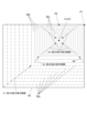
図19に戻り、CPU11は、拡大ボタン172a又は縮小ボタン172bに対する操作に応じて新たに設定される表示倍率の値(以下、「Next_Zoom」と記す)に基づいて、代表点Prが中央(例えば、中心)に位置する仮表示対象範囲40Tを特定する(ステップS305)。
Returning to FIG. 19, the
図21は、仮表示対象範囲40Tの例を示す図である。
仮表示対象範囲40Tは、抽出開始位置Ps(Start_X,StartY)、及び抽出終了位置Pe(End_X,End_Y)により表される。ステップS305では、以下の式により抽出開始位置Ps及び抽出終了位置Peが特定される。
Start_X=AF_X-ImageSize_H・NextZoom/2
Start_Y=AF_Y-ImageSize_V・NextZoom/2
End_X=AF_X+ImageSize_H・NextZoom/2
End_Y=AF_Y+ImageSize_V・NextZoom/2
FIG. 21 is a diagram showing an example of the temporary
The temporary
Start_X=AF_X-ImageSize_H・NextZoom/2
Start_Y=AF_Y-ImageSize_V・NextZoom/2
End_X=AF_X+ImageSize_H・NextZoom/2
End_Y=AF_Y+ImageSize_V・NextZoom/2
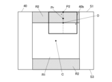
図21に示すように、仮表示対象範囲40Tは、代表点Prの位置及び表示倍率によっては、被写体画像40の範囲外の部分を含む場合がある。そこで、図19のステップS306では、CPU11は、仮表示対象範囲40Tが被写体画像40の範囲内に収まっているか否かを判別する。
As shown in FIG. 21, the temporary
仮表示対象範囲40Tが被写体画像40の範囲内に収まっていないと判別された場合には(ステップS306で“NO”)、CPU11は、被写体画像40に収まるように仮表示対象範囲40Tの位置を調整し、新たな表示対象範囲40Fとして確定させる(ステップS307)。詳しくは、ステップS307では、以下の(1)~(4)に従って抽出開始位置Ps及び抽出終了位置Peの座標が調整される。
If it is determined that the temporary
(1)Start_X<1の場合
この場合は、仮表示対象範囲40Tが被写体画像40の左端より左側に突出している。このため、仮表示対象範囲40Tの左端が被写体画像40の左端に揃うように以下の調整を行う。
Start_X=1
End_X=1+ImageSize_H/NextZoom
(1) When Start_X<1 In this case, the temporary
Start_X=1
End_X=1+ImageSize_H/NextZoom
(2)End_X>ImageSize_Hの場合
この場合は、仮表示対象範囲40Tが被写体画像40の右端より右側に突出している。このため、仮表示対象範囲40Tの右端が被写体画像40の右端に揃うように以下の調整を行う。
End_X=ImageSize_H
Start_X=End_X-ImageSize_H/NextZoom
(2) When End_X>ImageSize_H In this case, the temporary
End_X=ImageSize_H
Start_X=End_X-ImageSize_H/NextZoom
(3)Start_Y<1の場合
この場合は、仮表示対象範囲40Tが被写体画像40の上端より上側に突出している。このため、仮表示対象範囲40Tの上端が被写体画像40の上端に揃うように以下の調整を行う。
Start_Y=1
End_Y=1+ImageSize_V/NextZoom
(3) When Start_Y<1 In this case, the temporary
Start_Y=1
End_Y=1+ImageSize_V/NextZoom
(4)End_Y>ImageSize_Vの場合
この場合は、仮表示対象範囲40Tが被写体画像40の下端より下側に突出している。このため、仮表示対象範囲40Tの下端が被写体画像40の下端に揃うように以下の調整を行う。
End_Y=ImageSize_V
Start_Y=End_Y-ImageSize_V/NextZoom
(4) When End_Y>ImageSize_V In this case, the temporary
End_Y=ImageSize_V
Start_Y=End_Y-ImageSize_V/NextZoom
図22は、図21の仮表示対象範囲40Tに対して位置調整を行った状態を示す図である。
図21の仮表示対象範囲40Tは、被写体画像40に対して右側及び下側に突出しているため、ステップS307では上記の(2)、(4)の調整が行われる。この結果、図22に示すように、仮表示対象範囲40Tの右端及び下端が被写体画像40の右端及び下端に揃うように調整される。また、調整後の仮表示対象範囲40T(表示対象範囲40F)の中心Pc(Center_X,Center_Y)が、以下の式により特定される。
Center_X=Start_X+ImageSize_H/Next_Zoom/2
Center_Y=Start_Y+ImageSize_V/Next_Zoom/2
特定された中心Pcの座標は、次回の拡大縮小表示処理において中心Pocの座標として参照される。すなわち、以下の代入処理が行われる。
Old_Center_X←Center_X
Old_Center_Y←Center_Y
FIG. 22 is a diagram showing a state in which the position of the temporary
Since the temporary
Center_X=Start_X+ImageSize_H/Next_Zoom/2
Center_Y=Start_Y+ImageSize_V/Next_Zoom/2
The specified coordinates of the center Pc are referred to as the coordinates of the center Poc in the next enlargement/reduction display process. That is, the following substitution processing is performed.
Old_Center_X←Center_X
Old_Center_Y←Center_Y
図19に戻り、CPU11は、フォーカス位置Pf(DispAF_X,DispAF_Y)を、表示領域161aにおける代表点Prの表示位置に一致するように調整する(ステップS308)。この調整は、以下の式に従って行われる。
DispAF_X=((AF_X-Start_X)/ImageSize_H)・DisplayAreaSize_H・Next_Zoom
DispAF_Y=((AF_Y-Start_Y)/ImageSize_V)・DisplayAreaSize_V・Next_Zoom
Returning to FIG. 19, the
DispAF_X=((AF_X-Start_X)/ImageSize_H)・DisplayAreaSize_H・Next_Zoom
DispAF_Y=((AF_Y-Start_Y)/ImageSize_V)・DisplayAreaSize_V・Next_Zoom
次に、CPU11は、被写体画像40から新たな表示対象範囲40F(ステップS307で調整した仮表示対象範囲40T)を抽出し、フォーカスマーク161cとともに表示領域161aに表示させる(ステップS310)。このように、ステップS305~S308、S310の処理は、仮表示対象範囲40Tが被写体画像40の範囲外の部分を含む場合に、被写体画像40の範囲内となるように仮表示対象範囲40Tの位置を調整し、当該調整後の仮表示対象範囲40Tを表示対象範囲Fとして抽出する拡大表示制御に相当する。
Next, the
図23は、ステップS310における表示状態と、被写体画像40との関係を示す図である。
図23の下図に示すように、表示領域161aには、被写体画像40のうち抽出開始位置Ps及び抽出終了位置Peにより特定される表示対象範囲40Fが拡大表示される。また、当該表示においては、代表点Prの表示位置にフォーカス位置Pfが設定され、フォーカスマーク161cが表示される。
FIG. 23 is a diagram showing the relationship between the display state in step S310 and the
As shown in the lower diagram of FIG. 23, a
図21に示すように、仮表示対象範囲40Tが被写体画像40の範囲外の部分を含む場合において、仮表示対象範囲40Tの位置を調整して拡大後の表示対象範囲40Fを定める動作は、被写体画像40の縁部のうち仮表示対象範囲40Tと重なる部分に拡大基準点(拡大基準部分)を設定して当該拡大基準点P1を基準に拡大する動作に相当する。被写体画像40の縁部のうち仮表示対象範囲40Tと重なる部分が、被写体画像40の角部を含む場合には、当該角部に拡大基準点P1を設定して拡大する動作に相当する。より詳しくは、上記のステップS307における(1)又は(2)において、Start_X又はEnd_Xを調整する処理は、拡大基準点P1のX座標を定める処理に相当し、(3)又は(4)において、Start_Y又はEnd_Yを調整する処理は、拡大基準点P1のY座標を定める処理に相当する。図22に示す現在の表示対象範囲40Eから、新たな表示対象範囲40Fへの拡大は、拡大基準点P1及び代表点Prが含まれるように拡大後の表示対象範囲を抽出する処理に相当する。
As shown in FIG. 21, when the temporary
一方、例えば図24の上図に示すように、仮表示対象範囲40Tが被写体画像40の縁部の1辺のみから突出している場合には、ステップS307では、上記の(1)若しくは(2)の調整のみ、又は(3)若しくは(4)の調整のみが行われる(図24の例では、(2)の調整のみが行われる)。この結果、図24の下図に示すように、仮表示対象範囲40Tの1辺(ここでは、右辺S)が被写体画像40の縁部の一辺に揃うように調整される。この場合には、調整後の仮表示対象範囲40Tのうち被写体画像40の縁部に重なっている辺(右辺S)に含まれる各点が、拡大基準点に相当する。図24の下図に示す現在の表示対象範囲40Eから、新たな表示対象範囲40Fへの拡大は、右辺Sに位置する拡大基準点及び代表点Prが含まれるように拡大後の表示対象範囲を抽出する処理に相当する。言い換えると、調整後の仮表示対象範囲40Tのうち右辺Sが、拡大基準部分に相当する。図24の下図に示す現在の表示対象範囲40Eから、新たな表示対象範囲40Fへの拡大は、拡大基準部分としての右辺Sと、代表点Prと、が含まれるように拡大後の表示対象範囲を抽出する処理に相当する。
On the other hand, as shown in the upper diagram of FIG. 24, for example, if the temporary
一方、図19のステップS306において、仮表示対象範囲40Tが被写体画像40の範囲内に収まっていると判別された場合には(ステップS306で“YES”)、CPU11は、表示領域161aの中心点にフォーカス位置Pfを設定する(ステップS309)。また、CPU11は、ステップS305で特定した仮表示対象範囲40Tをそのまま新たな表示対象範囲40Fとして抽出し、フォーカスマーク161cとともに表示領域161aに表示させる(ステップS310)。このように、ステップS305、S306、S309、S310の処理は、仮表示対象範囲40Tが被写体画像40の範囲内にある場合に、仮表示対象範囲40Tを表示対象範囲Fとして抽出する拡大表示制御に相当する。ステップS310の処理が終了すると、CPU11は、拡大縮小表示処理を終了させる。
On the other hand, in step S306 of FIG. 19, if it is determined that the temporary
<変形例2>
次に、上記実施形態の変形例2について説明する。変形例2は、上記の変形例1と組み合わせてもよい。
<
Next, a second modification of the above embodiment will be described.
図25は、変形例2に係る被写体画像40の拡大表示動作を説明する図である。
図25のAに示すように、変形例2では、表示領域161aにおいてマトリクス状に配列されたグリッドGが設定されている。図25におけるグリッドの境界線は、説明の便宜上のものであり、実際の表示領域161aには表示されない。指定部分30を指定するためにユーザがタッチ操作を行うと、タッチ位置に最も近い1つのグリッドGが特定される。
FIG. 25 is a diagram illustrating an enlarged display operation of the
As shown in FIG. 25A, in the second modification, a grid G arranged in a matrix is set in the
各グリッドGには、任意の表示倍率が指定されたときの表示領域161aにおけるグリッド群の表示態様が予め設定されている。例えば、図25のAに示す右から2番目、上から2番目のグリッドGには、表示倍率の増大に従って、図25のB、C、Dに示すグリッド群の表示態様で表示がなされるような設定が予め対応付けられている。詳しくは、ある表示倍率が指定されたときに、図25のBに示すように、上端及び右端から縦横4.5×4.5個のグリッド群が表示されるように設定されている。また、ある表示倍率が指定されたときに、図25のCに示すように、上端及び右端から縦横3×3のマトリクス状にグリッド群が表示されるように設定されている。この状態で、当該グリッドGが表示領域161aの中央に表示されるため、以降は、図25のDに示すように、表示領域161aの中心点(原点O)を中心とした拡大表示が行われる。縮小時には、拡大時の逆の順序で表示を遷移させればよい。このような拡大表示動作及び縮小表示動作も、拡大基準点P1~P3を基準として被写体画像40を拡大表示する動作、及び縮小基準点P4~P6を基準として被写体画像40を縮小表示する動作に相当する。
For each grid G, the display mode of the grid group in the
このように、本変形例では、拡大/縮小時の表示態様がグリッドごとに予め設定されているため、代表点Prに基づいて表示対象範囲を都度算出する上記実施形態と比較して、簡易な処理で拡大表示及び縮小表示を行うことができる。 In this way, in this modification, the display mode when enlarging/reducing is set in advance for each grid, so it is simpler than the above embodiment in which the display target range is calculated each time based on the representative point Pr. Enlarged display and reduced display can be performed by processing.
<変形例3>
次に、上記実施形態の変形例3について説明する。変形例3は、上記の変形例1及び/又は変形例2と組み合わせてもよい。
<
Next, a third modification of the above embodiment will be described.
上記実施形態では、矩形の表示領域161aを例示したが、表示領域161aの形状は矩形に限られない。例えば、図26(a)に示す三角形や、図26(b)に示す八角形といった多角形であってもよく、また、図26(c)に示す円形又は楕円系等であってもよい。これらの場合には、等倍の被写体画像40を表示領域161aに表示させたときに表示領域161aの外周に相当する部分が、被写体画像40の縁部に対応する。取得した拡大率で、代表点Prが中央(例えば、中心)に位置する表示対象範囲を抽出できない場合には、上記の縁部に拡大基準点を設定する拡大表示制御を行うことで、上記実施形態と同様に、指定部分30の代表点Prが見切られないような拡大表示が可能である。本変形例における第1範囲R1は、被写体画像40の縁部(表示領域161aの外周)と相似形の範囲であって、表示対象範囲を、取得した拡大率に応じて、かつ、指定部分30の代表点Prが表示対象範囲の中央に位置するように、被写体画像40から抽出すると仮定した場合における表示対象範囲の中央が、第1範囲R1内に位置するように定められる。
In the above embodiment, the
例えば、図26(a)、(b)に示す多角形の表示領域161aの場合において、第1範囲R1を除いた範囲内に指定部分30の代表点Prがある場合には、当該多角形のうち指定部分30の代表点Prから最も近い角部に相当する点に拡大基準点P1を設定して拡大表示制御を実行すればよい。また、被写体画像40の縁部上のいずれかに位置し、かつ代表点Prからの距離が最短である点に拡大基準点P1を設定して拡大表示制御を行ってもよい。また、図26(c)に示す円形の表示領域161aの場合には、表示領域161aの中央(例えば、中心点:表示対象範囲の原点O)から代表点Prに向かって延びる線分と円との交点(すなわち、被写体画像40の縁部上のいずれかに位置し、かつ代表点Prからの距離が最短である点)に拡大基準点P1を設定して拡大表示制御を実行すればよい。角部のない他の図形、例えば楕円形などである場合にも同様の方法で拡大基準点P1を設定することができる。上記の拡大表示制御により代表点Pr及びフォーカス位置Pfが原点Oに到達した場合には、以降、代表点Prを拡大基準点とする第3の拡大表示制御を実行すればよい。
For example, in the case of the
<変形例4>
次に、上記実施形態の変形例4について説明する。変形例4は、上記の変形例1~3のうち任意の一部又は全部と組み合わせてもよい。
上記実施形態は、拡大基準点P1を基準とする第1の拡大表示制御の実施後に、拡大基準点P2を基準とする第2の拡大表示制御を実施することで、指定部分30の代表点Prが表示領域161aの中心点(表示対象範囲の原点O)に移動する表示態様であったが、このような2段階の表示に限定する趣旨ではない。例えば、図27に示すように、被写体画像40の中央(ここでは、中心O1)から指定部分30の代表点Prを通って被写体画像40の縁部に至る線分Lと、被写体画像40の縁部との交点に拡大基準点P7(拡大基準部分)を定め、この拡大基準点P7を基準に拡大してもよい。図27における点O2~O4は、拡大基準点P7を基準に被写体画像40から表示対象範囲40cまで拡大するときの、中間の表示対象範囲401~403の原点を示す。代表点Prは、各表示対象範囲401~403において、原点O2~O4と、拡大基準点P7とを結ぶ線分上に位置しており、表示対象範囲40cでは、原点O5に代表点Prが位置している。よって、拡大基準点P7を基準として拡大することで、表示倍率の増大とともに、代表点Prが表示領域161aの中心点に直線的に近づくような拡大表示を行うことができる。
<Modification 4>
Next, a fourth modification of the above embodiment will be described. Modification 4 may be combined with any part or all of
In the above embodiment, the representative point Pr of the specified
<効果>
以上のように、本実施形態に係る撮像装置1は、表示部16の表示動作を制御する処理部としてのCPU11を備える。CPU11は、撮像対象の被写体3を含む被写体画像40のうちの、第1のユーザ操作により指定された指定部分30を取得し、第2のユーザ操作に応じて、被写体画像40の一部を拡大して表示部16の表示領域161aに表示させる拡大表示制御を行い、拡大表示制御では、指定された指定部分30に応じて、被写体画像40に拡大基準部分としての拡大基準点を設定する。
これによれば、ユーザは、指定部分30を指定して拡大を指示する簡易な操作で、所望する指定部分30を含む拡大画像を表示させることができる。また、指定部分30に応じて拡大基準部分が設定されるので、被写体画像40から、指定部分30を含む範囲を適切に抽出して拡大表示することができる。このため、ユーザが表示対象範囲そのものを指定する従来技術と比較して、簡易かつ適切に被写体画像40の所望の部分を拡大表示させることができる。例えば、図2に示すように発光部15による照明を行いながら筒2を通して撮像を行う場合には、被写体画像40の中央から外れた位置に所望の指定部分30が位置していても、撮像装置1を動かさずに、照明状態を維持しつつ指定部分30を拡大表示させて観察することができる。また、表示の拡大を段階的に行うことが可能であるため、ユーザが所望する表示状態が得られやすい。
<Effect>
As described above, the
According to this, the user can display an enlarged image including the desired specified
また、CPU11は、拡大表示制御において、被写体画像40から、拡大基準部分及び指定部分30を含めるように表示対象範囲を抽出し、抽出された表示対象範囲を拡大して表示領域161aに表示させる。
これによれば、ユーザが所望する指定部分30を含むように拡大後の表示対象範囲が自動的に抽出されて表示されるため、簡易かつ適切に被写体画像40の所望の部分を拡大表示させることができる。
Further, in the enlargement display control, the
According to this, since the enlarged display target range is automatically extracted and displayed so as to include the specified
また、CPU11は、第2のユーザ操作に応じて、被写体画像40の拡大率を取得し、表示対象範囲を、取得した拡大率に応じて、かつ、指定部分30の代表点Prが表示対象範囲40の中央(例えば、中心)に位置するように、被写体画像40から抽出することができない場合には、拡大表示制御において、被写体画像40の縁部に拡大基準部分としての拡大基準点を設定する。これにより、指定部分30が表示領域161aから見切られず、かつ、代表点Prが表示領域161aの中央(例えば、中心点)に近付くような態様で表示を拡大することができる。
In addition, the
また、変形例1において、CPU11は、第2のユーザ操作に応じて、被写体画像40の拡大率を取得し、指定部分30の代表点Prと、取得した拡大率と、に基づいて、代表点Prが中央(例えば、中心)に位置する拡大後の仮表示対象範囲40Tを特定し、仮表示対象範囲40Tが被写体画像40の範囲外の部分を含む場合には、拡大表示制御において、被写体画像40の縁部のうち仮表示対象範囲40Tと重なる部分に拡大基準部分としての拡大基準点を設定する。これにより、ユーザが所望する指定部分30を含むように拡大後の表示対象範囲が自動的に抽出される表示動作を実現できる。
In addition, in the first modification, the
また、変形例1において、CPU11は、被写体画像40の縁部のうち仮表示対象範囲40Tと重なる部分が、被写体画像40の角部を含む場合には、当該角部に拡大基準点を設定する。これにより、指定部分30が表示領域161aから見切られず、かつ、代表点Prが表示領域161aの中央に近付くような態様で表示を拡大することができる。
Furthermore, in the first modification, when the portion of the edge of the
また、CPU11は、第2のユーザ操作に応じて、被写体画像の拡大率を取得し、被写体画像のうち、第1範囲R1を除いた範囲内に指定部分30の代表点Prがあるか否かを判別する。第1範囲R1は被写体画像40と相似形の範囲であって、表示対象範囲を、拡大率に応じて、かつ、指定部分30の代表点Prが表示対象範囲40の中央(例えば、中心)に位置するように、被写体画像40から抽出すると仮定した場合における表示対象範囲の中央が、第1範囲R1内に位置する。CPU11は、第1範囲R1を除いた範囲内に代表点Prがあると判別した場合には、拡大表示制御において、被写体画像40の縁部に拡大基準部分としての拡大基準点を設定する。これにより、第1範囲R1と代表点Prとの位置関係に基づく簡易な判別処理により、適切に拡大基準点を設定して表示を拡大することができる。
Further, the
また、被写体画像40は角部を有する形状の画像であってもよく、CPU11は、第1範囲R1を除いた範囲内に代表点Prがあると判別した場合には、拡大表示制御において、被写体画像40の縁部のうち代表点Prから最も近い角部を拡大基準部分として設定し、又は縁部上のいずれかに位置し、かつ代表点からの距離が最短である点を拡大基準部分として設定してもよい。これにより、被写体画像40が矩形を始めとする任意の多角形である場合において、指定部分30が表示領域161aから見切られず、かつ、代表点Prが表示領域161aの中央に近付くような態様で表示を拡大することができる。
Further, the
また、被写体画像40が矩形状の画像である場合に、CPU11は、被写体画像のうち、第1範囲、第2範囲及び第3範囲を除いた範囲内(すなわち、第4範囲R4内)に指定部分30の代表点Prがあるか否かを判別する。第1範囲R1は被写体画像40と相似形の矩形の範囲である。第2範囲R2は、矩形の範囲であって、被写体画像40の一の辺に平行なx方向についての第2範囲R2の幅が第1範囲R1と同一で、かつ、被写体画像40のうち、y方向について第1範囲R1よりも一方側及び他方側の部分にそれぞれ相当する範囲である。第3範囲R3は、矩形の範囲であって、y方向についての第3範囲R3の幅が第1範囲R1と同一で、かつ、被写体画像40のうち、x方向について第1範囲R1よりも一方側及び他方側の部分にそれぞれ相当する範囲である。CPU11は、第1範囲R1、第2範囲R2及び第3範囲R3を除いた範囲内に代表点Prがあると判別した場合には、第1の拡大表示制御において、被写体画像40の縁部のうち、指定部分30の代表点Prから最も近い角部に拡大基準点P1を設定する。このように拡大基準点P1を基準に拡大することで、指定部分30が表示領域161aから見切られず、かつ、代表点Prが表示領域161aの中央に近付くような態様で表示を拡大することができる。また、簡易な処理で適切な位置に拡大基準点P1を設定することができる。
Further, when the
また、被写体画像40が矩形状の画像である場合に、CPU11は、被写体画像40のうち、第2範囲R2内又は第3範囲R3内に指定部分30の代表点Prがあるか否かを判別する。CPU11は、代表点Prが第2範囲R2内にあると判別した場合には、被写体画像40のx方向に平行な上辺S1上及び下辺S3上のいずれかに位置し、かつ代表点Prからの距離が最短である点に拡大基準点P2を設定する。CPU11は、代表点Prが第3範囲R3内にあると判別した場合には、被写体画像40のy方向に平行な右辺S2上及び左辺S4上のいずれかに位置し、かつ代表点Prからの距離が最短である点に拡大基準点P2を設定する。このように拡大基準点P2を基準に拡大することで、指定部分30が表示領域161aから見切られず、かつ、x軸又はy軸に沿って代表点Prが表示領域161aの中央に近付くような態様で表示を拡大することができる。また、簡易な処理で適切な位置に拡大基準点P2を設定することができる。
Further, when the
また、CPU11は、第1範囲R1を除いた範囲内に代表点Prがあると判別した場合には、拡大表示制御において、被写体画像40の中央(例えば、中心)から指定部分30の代表点Prを通って被写体画像40の縁部に至る線分と、被写体画像40の縁部との交点に拡大基準点を設定してもよい。これにより、被写体画像40が円形を含む任意の形状である場合において、指定部分30が表示領域161aから見切られず、かつ、代表点Prが表示領域161aの中央に近付くような態様で表示を拡大することができる。
In addition, if the
また、CPU11は、第2のユーザ操作に応じて、被写体画像40の拡大率を取得し、被写体画像40のうち、第1範囲R1内に指定部分30の代表点Prがあるか否かを判別し、第1範囲R1内に代表点Prがあると判別した場合には、第3の拡大表示制御において、代表点Prに拡大基準点P3を設定して、代表点Prが中央(例えば、中心)に位置する表示対象範囲を被写体画像40から抽出する。これにより、指定部分30の表示位置を表示領域161aの中央に維持しつつ表示を拡大することができる。
Further, the
また、CPU11は、拡大表示制御において、拡大後における指定部分30の代表点Prと表示領域161aの中心点との距離が、拡大前における代表点Prと中心点との距離以下となるように拡大基準点を設定する。これにより、代表点Prが中心点に近付く態様で段階的に被写体画像40が拡大されるため、ユーザが所望する拡大表示状態がより得られやすい。
In addition, in the enlarged display control, the
また、CPU11は、拡大表示制御の開始後に受け付けられた第3のユーザ操作に応じて、被写体画像40における中心以外の所定の縮小基準部分としての縮小基準点を基準として当該被写体画像40を縮小して表示領域161aに表示させる縮小表示制御を行う。これにより、拡大表示制御により拡大された被写体画像40を縮小して表示させることができる。
Further, the
また、CPU11は、被写体画像40の縁部が、表示領域161aの外周のいずれの辺とも重なっていない場合には、縮小表示制御において、代表点Prを縮小基準点P4として設定する。これにより、指定部分30の表示位置を表示領域161aの中央に維持しつつ表示を縮小することができる。
Further, when the edge of the
また、CPU11は、被写体画像40の縁部の一部が、表示領域161aの外周のうちいずれか1辺と重なっている場合には、縮小表示制御において、x軸又はy軸と、上記の1辺との交点を縮小基準点P5として設定する。これにより、縮小後に、被写体画像40の範囲外の部分が表示領域161aに表示されないようにすることができる。
In addition, when a part of the edge of the
また、CPU11は、被写体画像40の縁部のうち直交している2辺が、表示領域161aの外周のうち直交している2辺と重なっている場合には、縮小表示制御において、被写体画像40の縁部のうち上記の2辺の交点を縮小基準点P6として設定する。これにより、縮小後に、被写体画像40の範囲外の部分が表示領域161aに表示されないようにすることができる。
In addition, when two orthogonal sides of the edge of the
また、本実施形態に係る撮像装置1は、表示部16の表示動作を制御する処理部としてのCPU11を備える。CPU11は、撮像対象の被写体3を含む被写体画像40のうちの、第1のユーザ操作により指定された指定部分30を取得し(図10のステップS103、及び図19のステップS304)、第2のユーザ操作に応じて、被写体画像40の拡大率を取得し(図10のステップS105、及び図19のステップS305)、取得された指定部分30を含む、取得された拡大率に応じた大きさの表示対象範囲を被写体画像40から抽出して表示部16の表示領域161aに表示させる拡大表示制御を行い(上記実施形態では、図10のステップS105~図11のS119。上記変形例1では、図19のステップS305~S310)、取得された指定部分30の位置と取得された拡大率とに応じて、被写体画像40から抽出される表示対象範囲が互いに異なる複数の拡大表示制御のうちいずれかを行う(上記実施形態では、図10のステップS109~S110、図11のステップS111~S113、ステップS114~S116、又はステップS117~S119のいずれかの拡大表示制御。上記変形例では、ステップS305~S308、S310を含む拡大表示制御、又はステップS305、S306、S309を含む拡大表示制御)。
これによれば、指定部分30及び拡大率に応じて、被写体画像40から指定部分30を含む範囲が適切に抽出されて拡大表示されるため、ユーザは、指定部分30を指定して拡大を指示する簡易な操作により、被写体画像40の所望の部分を適切に拡大表示させることができる。
Further, the
According to this, the range including the designated
また、CPU11は、指定部分30の代表点Prと、取得した拡大率と、に基づいて、代表点Prが中央(例えば、中心)に位置する拡大後の仮表示対象範囲40Tを特定し、仮表示対象範囲40Tが被写体画像40の範囲内にある場合には、仮表示対象範囲40Tを表示対象範囲として抽出する拡大表示制御を行い、仮表示対象範囲40Tが被写体画像40の範囲外の部分を含む場合には、指定部分30を含み、かつ被写体画像40の範囲内となるように仮表示対象範囲40Tの位置を調整し、当該調整後の仮表示対象範囲40Tを表示対象範囲として抽出する拡大表示制御を行う。これにより、ユーザが所望する指定部分30を含むように拡大後の表示対象範囲が自動的に抽出される表示動作を実現できる。
Further, the
また、本実施形態に係るプログラム131は、コンピュータとしてのCPU11に、表示部16の表示動作を制御する機能として、撮像対象の被写体3を含む被写体画像40のうちの、第1のユーザ操作により指定された指定部分30を取得する機能と、第2のユーザ操作に応じて、被写体画像40の一部を拡大して表示部16の表示領域161aに表示させる拡大表示制御を行う機能と、拡大表示制御において、指定された指定部分30に応じて、被写体画像40に拡大基準部分としての拡大基準点を設定する機能と、を実現させる。
これによれば、ユーザは、指定部分30を指定して拡大を指示する簡易な操作で、所望する指定部分30を含む拡大画像を表示させることができる。また、指定部分30に応じて拡大基準部分が設定されるので、被写体画像40から、指定部分30を含む範囲を適切に抽出して拡大表示することができる。このため、ユーザが表示対象範囲そのものを指定する従来技術と比較して、簡易かつ適切に被写体画像40の所望の部分を拡大表示させることができる。また、表示の拡大を段階的に行うことが可能であるため、ユーザが所望する表示状態が得られやすい。
In addition, the
According to this, the user can display an enlarged image including the desired specified
また、本実施形態に係るプログラム131は、コンピュータとしてのCPU11に、表示部16の表示動作を制御する機能として、撮像対象の被写体3を含む被写体画像40のうちの、第1のユーザ操作により指定された指定部分30を取得する機能と(図10のステップS103、及び図19のステップS304)、第2のユーザ操作に応じて、被写体画像40の拡大率を取得する機能と(図10のステップS105、及び図19のステップS305)、取得された指定部分30を含む、取得された拡大率に応じた大きさの表示対象範囲を被写体画像40から抽出して表示部16の表示領域161aに表示させる拡大表示制御を行う機能と(上記実施形態では、図10のステップS105~図11のS119。上記変形例1では、図19のステップS305~S310)、取得された指定部分30の位置と取得された拡大率とに応じて、被写体画像40から抽出される表示対象範囲が互いに異なる複数の拡大表示制御のうちいずれかを行う機能と(上記実施形態では、図10のステップS109~S110、図11のステップS111~S113、ステップS114~S116、又はステップS117~S119のいずれかの拡大表示制御。上記変形例では、ステップS305~S308、S310を含む拡大表示制御、又はステップS305、S306、S309を含む拡大表示制御)、を実現させる。
これによれば、指定部分30及び拡大率に応じて、被写体画像40から指定部分30を含む範囲が適切に抽出されて拡大表示されるため、ユーザは、指定部分30を指定して拡大を指示する簡易な操作により、被写体画像40の所望の部分を適切に拡大表示させることができる。
In addition, the
According to this, the range including the designated
また、本実施形態に係る被写体画像の表示方法は、撮像対象の被写体3を含む被写体画像40の表示方法であって、被写体画像40のうちの、第1のユーザ操作により指定された指定部分30を取得する第1ステップと、第2のユーザ操作に応じて、被写体画像40の一部を拡大して表示部16の表示領域161aに表示させる第2ステップと、を含み、第3ステップでは、指定された指定部分30に応じて、被写体画像40に拡大基準部分としての拡大基準点を設定する。
これによれば、ユーザは、指定部分30を指定して拡大を指示する簡易な操作で、所望する指定部分30を含む拡大画像を表示させることができる。また、指定部分30に応じて拡大基準部分が設定されるので、被写体画像40から、指定部分30を含む範囲を適切に抽出して拡大表示することができる。このため、ユーザが表示対象範囲そのものを指定する従来技術と比較して、簡易かつ適切に被写体画像40の所望の部分を拡大表示させることができる。また、表示の拡大を段階的に行うことが可能であるため、ユーザが所望する表示状態が得られやすい。
Further, the display method of a subject image according to the present embodiment is a method of displaying a
According to this, the user can display an enlarged image including the desired specified
また、本実施形態に係る被写体画像の表示方法は、撮像対象の被写体3を含む被写体画像40の表示方法であって、被写体画像40のうちの、第1のユーザ操作により指定された指定部分30を取得するステップと(図10のステップS103、及び図19のステップS304)、第2のユーザ操作に応じて、被写体画像40の拡大率を取得するステップと(図10のステップS105、及び図19のステップS305)、取得された指定部分30を含む、取得された拡大率に応じた大きさの表示対象範囲を被写体画像40から抽出して表示部16の表示領域161aに表示させる拡大表示制御を行うステップと(図10のステップS105~図11のS119。上記変形例1では、図19のステップS305~S310)、取得された指定部分30の位置と取得された拡大率とに応じて、被写体画像40から抽出される表示対象範囲が互いに異なる複数の拡大表示制御のうちいずれかを行うステップと(上記実施形態では、図10のステップS109~S110、図11のステップS111~S113、ステップS114~S116、又はステップS117~S119のいずれかの拡大表示制御。上記変形例では、ステップS305~S308、S310を含む拡大表示制御、又はステップS305、S306、S309を含む拡大表示制御)を含む。
これによれば、指定部分30及び拡大率に応じて、被写体画像40から指定部分30を含む範囲が適切に抽出されて拡大表示されるため、ユーザは、指定部分30を指定して拡大を指示する簡易な操作により、被写体画像40の所望の部分を適切に拡大表示させることができる。
Further, the display method of a subject image according to the present embodiment is a method of displaying a
According to this, the range including the designated
<その他>
なお、上記実施形態における記述は、本発明に係る撮像装置、プログラム及び被写体画像の表示方法の一例であり、これに限定されるものではない。
例えば、筒2を用いない通常の撮像においても、上記実施形態の被写体画像40の表示方法を適用可能である。
<Others>
Note that the description in the above embodiment is an example of the imaging device, program, and method of displaying a subject image according to the present invention, and the present invention is not limited thereto.
For example, the method of displaying the
また、表示画面161のうち一部の表示領域161aに被写体画像40及びその拡大画像を表示する例を用いて説明したが、これに限られず、表示画面161の全体を被写体画像40及びその拡大画像の表示領域としてもよい。
Furthermore, although the description has been made using an example in which the
また、撮像装置1は、ユーザが手に持って操作するデジタルカメラに限られず、被写体の撮像の際に表示部において被写体画像を表示可能な任意の撮像装置であってもよい。
Furthermore, the
上記実施形態では、撮像装置1の表示部16に被写体画像40を表示させる場合を例示したが、これに限られない。例えば、撮像装置1の外部に設けられた表示部における被写体画像の表示を撮像装置1のコンピュータが制御する場合に本発明を適用してもよい。また、撮像装置1以外の任意の情報処理装置のコンピュータが、任意の表示部における被写体画像の表示を制御する場合に本発明を適用してもよい。これらの場合には、例えば、タッチパネルが設けられた表示部に被写体画像を表示させて指定部分をユーザに指定させ、ユーザの操作に応じてコンピュータが拡大表示制御及び縮小表示制御を行えばよい。また、表示対象の被写体画像は、撮像される画角を示すスルー画(ライブビュー画像)に限られず、撮像動作を行って記録された被写体画像であってもよい。すなわち、撮像済の被写体画像を再生表示する場合に本発明を適用してもよい。
In the embodiment described above, the case where the
拡大基準部分として拡大基準点P1~P3、P7を例示したが、拡大基準部分は点に限られず、被写体画像の縁部のうちの、ある範囲に亘る一部であってもよい。また、縮小基準部分として縮小基準点P4~P6を例示したが、縮小基準部分は点に限られず、被写体画像の縁部のうちの、ある範囲に亘る一部であってもよい。また、拡大基準点及び縮小基準点は、被写体画像の縁部を除いた内部に設定されてもよい。 Although the enlargement reference points P1 to P3 and P7 are illustrated as the enlargement reference portions, the enlargement reference portions are not limited to points, but may be a part of the edge of the subject image over a certain range. Further, although the reduction reference points P4 to P6 are illustrated as the reduction reference portion, the reduction reference portion is not limited to points, and may be a part of the edge of the subject image over a certain range. Further, the enlargement reference point and the reduction reference point may be set inside the subject image excluding the edges.
また、上記実施形態では、表示対象範囲を、取得した拡大率に応じて、かつ、指定部分30の代表点Prが表示対象範囲の中心に位置するように、被写体画像40から抽出することができない場合に、拡大表示制御において、被写体画像40の縁部に拡大基準部分を設定する例を用いて説明したが、これに限定されない。これに代えて、表示対象範囲を、取得した拡大率に応じて、かつ、指定部分30の代表点Prが表示対象範囲の中央(中心点近傍の所定範囲)に位置するように、被写体画像40から抽出することができない場合に、拡大表示制御において、被写体画像40の縁部に拡大基準部分を設定してもよい。
また、指定部分30の代表点Prが表示対象範囲の中央に位置するように被写体画像40から表示対象範囲を抽出することができる場合に、抽出後の表示対象範囲において、代表点Prは必ずしも表示対象範囲の中心点に位置していなくてもよく、中央に位置していてもよい。
Furthermore, in the above embodiment, the display target range cannot be extracted from the
Further, when the display target range can be extracted from the
また、以上の説明では、本発明に係るプログラムのコンピュータ読み取り可能な媒体として記憶部13を使用した例を開示したが、この例に限定されない。その他のコンピュータ読み取り可能な媒体として、HDD、SSD、フラッシュメモリ、CD-ROM等の情報記録媒体を適用することが可能である。また、本発明に係るプログラムのデータを通信回線を介して提供する媒体として、キャリアウエーブ(搬送波)も本発明に適用される。
Further, in the above description, an example in which the
また、上記実施形態における撮像装置1の構成要素の細部構成及び細部動作に関しては、本発明の趣旨を逸脱することのない範囲で適宜変更可能であることは勿論である。
Further, it goes without saying that the detailed configuration and detailed operation of the components of the
本発明の実施の形態を説明したが、本発明の範囲は、上述の実施の形態に限定するものではなく、特許請求の範囲に記載された発明の範囲とその均等の範囲を含む。
以下に、この出願の願書に最初に添付した特許請求の範囲に記載した発明を付記する。付記に記載した請求項の項番は、この出願の願書に最初に添付した特許請求の範囲の通りである。
〔付記〕
<請求項1>
表示部の表示動作を制御する処理部を備え、
前記処理部は、
撮像対象の被写体を含む被写体画像のうちの、第1のユーザ操作により指定された指定部分を取得し、
第2のユーザ操作に応じて、前記被写体画像の一部を拡大して前記表示部の表示領域に表示させる拡大表示制御を行い、
前記拡大表示制御では、前記指定された指定部分に応じて、前記被写体画像に拡大基準部分を設定する、
撮像装置。
<請求項2>
前記処理部は、
前記拡大表示制御において、前記被写体画像から、前記拡大基準部分及び前記指定部分を含めるように表示対象範囲を抽出し、前記抽出された表示対象範囲を拡大して前記表示領域に表示させる、
請求項1に記載の撮像装置。
<請求項3>
前記処理部は、
前記第2のユーザ操作に応じて、前記被写体画像の拡大率を取得し、
前記表示対象範囲を、前記拡大率に応じて、かつ、前記指定部分の代表点が前記表示対象範囲の中央に位置するように、前記被写体画像から抽出することができない場合には、前記拡大表示制御において、前記被写体画像の縁部に前記拡大基準部分を設定する、
請求項2に記載の撮像装置。
<請求項4>
前記処理部は、
前記第2のユーザ操作に応じて、前記被写体画像の拡大率を取得し、
前記指定部分の代表点と、前記拡大率と、に基づいて、前記代表点が中央に位置する拡大後の仮表示対象範囲を特定し、
前記仮表示対象範囲が前記被写体画像の範囲外の部分を含む場合には、前記拡大表示制御において、前記被写体画像の縁部のうち前記仮表示対象範囲と重なる部分に前記拡大基準部分を設定する、
請求項1~3のいずれか一項に記載の撮像装置。
<請求項5>
前記被写体画像は角部を有する形状の画像であり、
前記処理部は、
前記被写体画像の前記縁部のうち前記仮表示対象範囲と重なる部分が、前記被写体画像の角部を含む場合には、当該角部を前記拡大基準部分として設定する、
請求項4に記載の撮像装置。
<請求項6>
前記処理部は、
前記第2のユーザ操作に応じて、前記被写体画像の拡大率を取得し、
前記被写体画像のうち、第1範囲を除いた範囲内に前記指定部分の代表点があるか否かを判別し、
前記第1範囲は前記被写体画像と相似形の範囲であって、前記表示対象範囲を、前記拡大率に応じて、かつ、前記指定部分の代表点が前記表示対象範囲の中央に位置するように、前記被写体画像から抽出すると仮定した場合における前記表示対象範囲の中央が、前記第1範囲内に位置し、
前記処理部は、前記第1範囲を除いた範囲内に前記代表点があると判別した場合には、前記拡大表示制御において、前記被写体画像の縁部に前記拡大基準部分を設定する、
請求項2又は3に記載の撮像装置。
<請求項7>
前記被写体画像は角部を有する形状の画像であり、
前記処理部は、
前記第1範囲を除いた範囲内に前記代表点があると判別した場合には、前記拡大表示制御において、前記被写体画像の縁部のうち前記代表点から最も近い角部を前記拡大基準部分として設定し、又は前記縁部上のいずれかに位置し、かつ前記代表点からの距離が最短である点を前記拡大基準部分として設定する、
請求項6に記載の撮像装置。
<請求項8>
前記被写体画像は矩形状の画像であり、
前記処理部は、
前記被写体画像のうち、前記第1範囲、第2範囲及び第3範囲を除いた範囲内に前記指定部分の代表点があるか否かを判別し、
前記第1範囲は前記被写体画像と相似形の矩形の範囲であり、
前記第2範囲は、矩形の範囲であって、前記被写体画像の一の辺に平行な第1方向についての前記第2範囲の幅が前記第1範囲と同一で、かつ、前記被写体画像のうち、前記第1方向と直交する第2方向について前記第1範囲よりも一方側及び他方側の部分にそれぞれ相当する範囲であり、
前記第3範囲は、矩形の範囲であって、前記第2方向についての前記第3範囲の幅が前記第1範囲と同一で、かつ、前記被写体画像のうち、前記第1方向について前記第1範囲よりも一方側及び他方側の部分にそれぞれ相当する範囲であり、
前記処理部は、前記第1範囲、前記第2範囲及び前記第3範囲を除いた範囲内に前記代表点があると判別した場合には、前記拡大表示制御において、前記被写体画像の縁部のうち、前記指定部分の代表点から最も近い角部を前記拡大基準部分として設定する、
請求項6に記載の撮像装置。
<請求項9>
前記被写体画像は矩形状の画像であり、
前記処理部は、
前記被写体画像のうち、第2範囲内又は第3範囲内に前記指定部分の代表点があるか否かを判別し、
前記第1範囲は前記被写体画像と相似形の矩形の範囲であり、
前記第2範囲は、矩形の範囲であって、前記被写体画像の一の辺に平行な第1方向についての前記第2範囲の幅が前記第1範囲と同一で、かつ、前記被写体画像のうち、前記第1方向と直交する第2方向について前記第1範囲よりも一方側及び他方側の部分にそれぞれ相当する範囲であり、
前記第3範囲は、矩形の範囲であって、前記第2方向についての前記第3範囲の幅が前記第1範囲と同一で、かつ、前記被写体画像のうち、前記第1方向について前記第1範囲よりも一方側及び他方側の部分にそれぞれ相当する範囲であり、
前記処理部は、
前記代表点が前記第2範囲内にあると判別した場合には、前記拡大表示制御において、前記被写体画像の前記第1方向に平行な2つの辺上のいずれかに位置し、かつ前記代表点からの距離が最短である点を、前記拡大基準部分として設定し、
前記代表点が前記第3範囲内にあると判別した場合には、前記拡大表示制御において、前記被写体画像の前記第2方向に平行な2つの辺上のいずれかに位置し、かつ前記代表点からの距離が最短である点を前記拡大基準部分として設定する、
請求項6又は8に記載の撮像装置。
<請求項10>
前記処理部は、
前記第1範囲を除いた範囲内に前記代表点があると判別した場合には、前記拡大表示制御において、前記被写体画像の中央から前記指定部分の代表点を通って前記被写体画像の縁部に至る線分と、前記被写体画像の縁部との交点を前記拡大基準部分として設定する、
請求項6に記載の撮像装置。
<請求項11>
前記処理部は、
前記第2のユーザ操作に応じて、前記被写体画像の拡大率を取得し、
前記被写体画像のうち、第1範囲内に前記指定部分の代表点があるか否かを判別し、
前記第1範囲は前記被写体画像と相似形の範囲であって、前記表示対象範囲を、前記拡大率に応じて、かつ、前記指定部分の代表点が前記表示対象範囲の中央に位置するように、前記被写体画像から抽出すると仮定した場合における前記表示対象範囲の中央が、前記第1範囲内に位置し、
前記処理部は、前記第1範囲内に前記代表点があると判別した場合には、前記拡大表示制御において、前記代表点を前記拡大基準部分として設定して、前記代表点が中央に位置する前記表示対象範囲を前記被写体画像から抽出する、
請求項2、3、6~10のいずれか一項に記載の撮像装置。
<請求項12>
前記処理部は、
前記拡大表示制御において、拡大後における前記指定部分の代表点と前記表示領域の中心点との距離が、拡大前における前記代表点と前記中心点との距離以下となるように前記拡大基準部分を設定する、
請求項1~11のいずれか一項に記載の撮像装置。
<請求項13>
前記処理部は、
前記拡大表示制御の開始後に受け付けられた第3のユーザ操作に応じて、前記被写体画像における所定の縮小基準部分を基準として当該被写体画像を縮小して前記表示領域に表示させる縮小表示制御を行う、
請求項1~12のいずれか一項に記載の撮像装置。
<請求項14>
前記処理部は、
前記被写体画像の縁部が、前記表示領域の外周のいずれの辺とも重なっていない場合には、前記縮小表示制御において、前記指定部分の代表点を前記縮小基準部分として設定する、
請求項13に記載の撮像装置。
<請求項15>
前記処理部は、
前記被写体画像の縁部の一部が、前記表示領域の外周のうちいずれか1辺と重なっている場合には、前記縮小表示制御において、前記表示領域に表示されている前記被写体画像の表示対象範囲において前記表示領域の中心点に対応する原点を通る第1軸、又は前記原点を通り前記第1軸に垂直な第2軸と、前記1辺との交点を前記縮小基準部分として設定する、
請求項13又は14に記載の撮像装置。
<請求項16>
前記処理部は、
前記被写体画像の縁部のうち直交している2辺が、前記表示領域の外周のうち直交している2辺と重なっている場合には、前記縮小表示制御において、前記被写体画像の縁部のうち前記2辺の交点を前記縮小基準部分として設定する、
請求項13~15のいずれか一項に記載の撮像装置。
<請求項17>
表示部の表示動作を制御する処理部を備え、
前記処理部は、
撮像対象の被写体を含む被写体画像のうちの、第1のユーザ操作により指定された指定部分を取得し、
第2のユーザ操作に応じて、前記被写体画像の拡大率を取得し、
前記取得された指定部分を含む、前記取得された拡大率に応じた大きさの表示対象範囲を前記被写体画像から抽出して前記表示部の表示領域に表示させる拡大表示制御を行い、
前記取得された指定部分の位置と前記取得された拡大率とに応じて、前記被写体画像から抽出される表示対象範囲が互いに異なる複数の前記拡大表示制御のうちいずれかを行う、
撮像装置。
<請求項18>
前記処理部は、
前記指定部分の代表点と、前記拡大率と、に基づいて、前記代表点が中央に位置する拡大後の仮表示対象範囲を特定し、
前記仮表示対象範囲が前記被写体画像の範囲内にある場合には、前記仮表示対象範囲を前記表示対象範囲として抽出する前記拡大表示制御を行い、
前記仮表示対象範囲が前記被写体画像の範囲外の部分を含む場合には、前記指定部分を含み、かつ前記被写体画像の範囲内となるように前記仮表示対象範囲の位置を調整し、当該調整後の前記仮表示対象範囲を前記表示対象範囲として抽出する前記拡大表示制御を行う、
請求項17に記載の撮像装置。
<請求項19>
コンピュータに、表示部の表示動作を制御する機能として、
撮像対象の被写体を含む被写体画像のうちの、第1のユーザ操作により指定された指定部分を取得する機能と、
第2のユーザ操作に応じて、前記被写体画像の一部を拡大して前記表示部の表示領域に表示させる拡大表示制御を行う機能と、
前記拡大表示制御において、前記指定された指定部分に応じて、前記被写体画像に拡大基準部分を設定する機能と、
を実現させるプログラム。
<請求項20>
コンピュータに、表示部の表示動作を制御する機能として、
撮像対象の被写体を含む被写体画像のうちの、第1のユーザ操作により指定された指定部分を取得する機能と、
第2のユーザ操作に応じて、前記被写体画像の拡大率を取得する機能と、
前記取得された指定部分を含む、前記取得された拡大率に応じた大きさの表示対象範囲を前記被写体画像から抽出して前記表示部の表示領域に表示させる拡大表示制御を行う機能と、
前記取得された指定部分の位置と前記取得された拡大率とに応じて、前記被写体画像から抽出される表示対象範囲が互いに異なる複数の前記拡大表示制御のうちいずれかを行う機能と、
を実現させるプログラム。
<請求項21>
撮像対象の被写体を含む被写体画像の表示方法であって、
前記被写体画像のうちの、第1のユーザ操作により指定された指定部分を取得する第1ステップと、
第2のユーザ操作に応じて、前記被写体画像の一部を拡大して表示部の表示領域に表示させる第2ステップと、
を含み、
前記第2ステップでは、前記指定された指定部分に応じて、前記被写体画像に拡大基準部分を設定する、
被写体画像の表示方法。
<請求項22>
撮像対象の被写体を含む被写体画像の表示方法であって、
前記被写体画像のうちの、第1のユーザ操作により指定された指定部分を取得するステップと、
第2のユーザ操作に応じて、前記被写体画像の拡大率を取得するステップと、
前記取得された指定部分を含む、前記取得された拡大率に応じた大きさの表示対象範囲を前記被写体画像から抽出して表示部の表示領域に表示させる拡大表示制御を行うステップと、
前記取得された指定部分の位置と前記取得された拡大率とに応じて、前記被写体画像から抽出される表示対象範囲が互いに異なる複数の前記拡大表示制御のうちいずれかを行うステップと、
を含む、被写体画像の表示方法。
Although the embodiments of the present invention have been described, the scope of the present invention is not limited to the above-described embodiments, but includes the scope of the invention described in the claims and equivalent ranges thereof.
Below, the invention described in the claims first attached to the application of this application will be added. The claim numbers listed in the supplementary notes are as in the claims originally attached to the request for this application.
[Additional note]
<Claim 1>
comprising a processing unit that controls the display operation of the display unit,
The processing unit includes:
Obtaining a designated portion designated by a first user operation of the subject image including the subject to be imaged;
performing enlargement display control to enlarge a part of the subject image and display it in the display area of the display unit in response to a second user operation;
In the enlargement display control, an enlargement reference portion is set in the subject image according to the designated portion.
Imaging device.
<Claim 2>
The processing unit includes:
In the enlargement display control, a display target range is extracted from the subject image so as to include the enlargement reference part and the designated part, and the extracted display target range is enlarged and displayed in the display area.
The imaging device according to
<Claim 3>
The processing unit includes:
obtaining an enlargement ratio of the subject image in response to the second user operation;
If the display target range cannot be extracted from the subject image in accordance with the enlargement ratio and such that the representative point of the designated portion is located at the center of the display target range, the enlarged display is performed. In the control, setting the enlargement reference portion at an edge of the subject image;
The imaging device according to
<Claim 4>
The processing unit includes:
obtaining an enlargement ratio of the subject image in response to the second user operation;
Based on the representative point of the specified portion and the enlargement rate, specifying an enlarged temporary display target range in which the representative point is located in the center;
When the temporary display target range includes a part outside the range of the subject image, in the enlargement display control, the enlargement reference part is set at a part of the edge of the subject image that overlaps with the temporary display target range. ,
The imaging device according to any one of
<Claim 5>
The subject image is an image having a corner,
The processing unit includes:
If a portion of the edge of the subject image that overlaps with the temporary display target range includes a corner of the subject image, setting the corner as the enlargement reference portion;
The imaging device according to claim 4.
<Claim 6>
The processing unit includes:
obtaining an enlargement ratio of the subject image in response to the second user operation;
determining whether there is a representative point of the specified portion within the range excluding the first range of the subject image;
The first range is a range similar to the subject image, and the display target range is adjusted so that the representative point of the specified portion is located at the center of the display target range according to the enlargement rate. , the center of the display target range when extracted from the subject image is located within the first range,
When the processing unit determines that the representative point is within a range excluding the first range, the processing unit sets the enlargement reference portion at an edge of the subject image in the enlargement display control.
The imaging device according to
<Claim 7>
The subject image is an image having a corner,
The processing unit includes:
If it is determined that the representative point is within a range excluding the first range, in the enlarged display control, a corner of the edge of the subject image that is closest to the representative point is set as the enlarged reference part. or setting a point located somewhere on the edge and having the shortest distance from the representative point as the enlarged reference portion;
The imaging device according to claim 6.
<Claim 8>
The subject image is a rectangular image,
The processing unit includes:
Determining whether or not there is a representative point of the designated portion within a range of the subject image excluding the first range, second range, and third range;
The first range is a rectangular range similar to the subject image,
The second range is a rectangular range, the width of the second range in a first direction parallel to one side of the subject image is the same as the first range, and , ranges corresponding to parts on one side and the other side of the first range in a second direction orthogonal to the first direction,
The third range is a rectangular range, the width of the third range in the second direction is the same as the first range, and the width of the third range in the second direction is the same as that of the first range in the first direction. A range that corresponds to a part on one side and a part on the other side of the range, respectively,
When the processing unit determines that the representative point is within a range excluding the first range, the second range, and the third range, the processing unit controls the enlargement display control by adjusting the edge of the subject image. Among them, the corner closest to the representative point of the designated portion is set as the enlargement reference portion;
The imaging device according to claim 6.
<Claim 9>
The subject image is a rectangular image,
The processing unit includes:
determining whether there is a representative point of the designated portion within a second range or a third range of the subject image;
The first range is a rectangular range similar to the subject image,
The second range is a rectangular range, the width of the second range in a first direction parallel to one side of the subject image is the same as the first range, and , ranges corresponding to parts on one side and the other side of the first range in a second direction orthogonal to the first direction,
The third range is a rectangular range, the width of the third range in the second direction is the same as the first range, and the width of the third range in the second direction is the same as that of the first range in the first direction. A range that corresponds to a part on one side and a part on the other side of the range, respectively,
The processing unit includes:
If it is determined that the representative point is within the second range, in the enlarged display control, the representative point is located on either of two sides of the subject image parallel to the first direction, and Set the point at which the distance from the point is the shortest as the enlargement reference part,
If it is determined that the representative point is within the third range, in the enlarged display control, the representative point is located on either of two sides parallel to the second direction of the subject image, and setting the point at which the distance from the point is the shortest as the enlargement reference portion;
The imaging device according to claim 6 or 8.
<Claim 10>
The processing unit includes:
If it is determined that the representative point is within a range excluding the first range, in the enlarged display control, the image is moved from the center of the subject image to the edge of the subject image through the representative point of the specified portion. setting an intersection between a line segment leading thereto and an edge of the subject image as the enlargement reference portion;
The imaging device according to claim 6.
<Claim 11>
The processing unit includes:
obtaining an enlargement ratio of the subject image in response to the second user operation;
determining whether there is a representative point of the designated portion within a first range of the subject image;
The first range is a range similar to the subject image, and the display target range is adjusted so that the representative point of the specified portion is located at the center of the display target range according to the enlargement rate. , the center of the display target range when extracted from the subject image is located within the first range,
When the processing unit determines that the representative point is within the first range, the processing unit sets the representative point as the enlargement reference portion in the enlarged display control, and positions the representative point at the center. extracting the display target range from the subject image;
The imaging device according to any one of
<Claim 12>
The processing unit includes:
In the enlarged display control, the enlarged reference portion is adjusted such that the distance between the representative point of the designated portion and the center point of the display area after enlargement is equal to or less than the distance between the representative point and the center point before enlargement. set,
The imaging device according to any one of
<Claim 13>
The processing unit includes:
performing reduction display control to reduce the subject image based on a predetermined reduction reference portion in the subject image and display it in the display area in response to a third user operation accepted after the start of the enlargement display control;
The imaging device according to any one of
<Claim 14>
The processing unit includes:
If the edge of the subject image does not overlap with any side of the outer periphery of the display area, in the reduction display control, a representative point of the designated portion is set as the reduction reference portion;
The imaging device according to
<Claim 15>
The processing unit includes:
If a part of the edge of the subject image overlaps with any one side of the outer periphery of the display area, in the reduction display control, the display target of the subject image displayed in the display area is setting the intersection of the one side with a first axis passing through the origin corresponding to the center point of the display area in the range, or a second axis passing through the origin and perpendicular to the first axis as the reduction reference portion;
The imaging device according to claim 13 or 14.
<Claim 16>
The processing unit includes:
If two orthogonal sides of the edge of the subject image overlap two orthogonal sides of the outer periphery of the display area, in the reduction display control, the edge of the subject image is setting the intersection of the two sides as the reduction reference portion;
The imaging device according to any one of
<Claim 17>
comprising a processing unit that controls the display operation of the display unit,
The processing unit includes:
Obtaining a designated portion designated by a first user operation of the subject image including the subject to be imaged;
obtaining an enlargement ratio of the subject image in response to a second user operation;
Extracting from the subject image a display target range including the acquired specified portion and having a size according to the acquired magnification rate, and performing magnification display control to display it in a display area of the display unit;
performing one of the plurality of enlarged display controls in which display target ranges extracted from the subject image differ from each other according to the obtained position of the specified portion and the obtained enlargement rate;
Imaging device.
<Claim 18>
The processing unit includes:
Based on the representative point of the specified portion and the enlargement rate, specifying an enlarged temporary display target range in which the representative point is located in the center;
If the temporary display target range is within the range of the subject image, performing the enlarged display control to extract the temporary display target range as the display target range,
If the temporary display target range includes a part outside the range of the subject image, adjust the position of the temporary display target range so that it includes the specified part and is within the range of the subject image, and adjust the position. performing the enlarged display control to extract the subsequent temporary display target range as the display target range;
The imaging device according to
<Claim 19>
The computer has a function that controls the display operation of the display section.
a function of acquiring a designated portion designated by a first user operation of a subject image including the subject to be imaged;
A function for performing enlargement display control for enlarging a part of the subject image and displaying it in a display area of the display unit in response to a second user operation;
In the enlargement display control, a function of setting an enlargement reference portion in the subject image according to the designated portion;
A program that makes this possible.
<Claim 20>
The computer has a function that controls the display operation of the display section.
a function of acquiring a designated portion designated by a first user operation of a subject image including the subject to be imaged;
a function of acquiring an enlargement ratio of the subject image in response to a second user operation;
a function of performing enlarged display control to extract a display target range of a size according to the obtained enlargement rate from the subject image and display it in a display area of the display unit, including the obtained specified portion;
a function of performing one of the plurality of enlarged display controls in which display target ranges extracted from the subject image differ from each other according to the obtained position of the specified portion and the obtained enlargement rate;
A program that makes this possible.
<Claim 21>
A method for displaying a subject image including a subject to be imaged, the method comprising:
a first step of acquiring a designated portion of the subject image designated by a first user operation;
a second step of enlarging a part of the subject image and displaying it in a display area of a display unit in response to a second user operation;
including;
In the second step, an enlargement reference portion is set in the subject image according to the specified designated portion.
How to display the subject image.
<Claim 22>
A method for displaying a subject image including a subject to be imaged, the method comprising:
acquiring a designated portion of the subject image designated by a first user operation;
obtaining an enlargement ratio of the subject image in response to a second user operation;
Extracting from the subject image a display target range including the acquired specified portion and having a size corresponding to the acquired magnification rate and performing enlarged display control to display it in a display area of a display unit;
performing one of the plurality of enlarged display controls in which display target ranges extracted from the subject image differ from each other according to the obtained position of the specified portion and the obtained enlargement rate;
How to display the subject image, including:
1 撮像装置
2 筒
3 被写体
11 CPU(処理部)
12 RAM
13 記憶部
131 プログラム
14 撮像部
15 発光部
16 表示部
161 表示画面
161a 表示領域
161b 操作アイコン領域
161c フォーカスマーク
161d 撮像アイコン
17 操作部
171 タッチパネル
172 操作ボタン
172a 拡大ボタン
172b 縮小ボタン
172c モード変更ボタン
172d 再生ボタン
18 バス
30 指定部分
40 被写体画像
40a~40c、40E、40F 表示対象範囲
40T 仮表示対象範囲
G グリッド
O 原点
P1~P3、P7 拡大基準点(拡大基準部分)
P4~P6 縮小基準点(縮小基準部分)
Pf フォーカス位置
Pr 代表点
R1 第1範囲
R2 第2範囲
R3 第3範囲
R4 第4範囲
1
12 RAM
13
P4 to P6 Reduction reference point (reduction reference part)
Pf Focus position Pr Representative point R1 First range R2 Second range R3 Third range R4 Fourth range
Claims (20)
前記処理部は、
撮像対象の被写体を含む被写体画像のうちの、第1のユーザ操作により指定された指定部分を取得し、
前記第1のユーザ操作後に第2のユーザ操作がされる毎に、前記被写体画像の一部を段階的に拡大して前記表示部の表示領域に表示させる拡大表示制御を行い、
前記拡大表示制御では、前記指定された指定部分に応じて、前記段階的に拡大した後の前記指定部分が前記表示領域の中心に表示されるように前記被写体画像に拡大基準部分を設定し、
前記第2のユーザ操作に応じて、前記被写体画像の拡大率を取得し、
前記指定部分の代表点と、前記拡大率と、に基づいて、前記代表点が中央に位置する拡大後の仮表示対象範囲を特定し、
前記仮表示対象範囲が前記被写体画像の範囲外の部分を含む場合には、前記拡大表示制御において、前記被写体画像の縁部のうち前記仮表示対象範囲と重なる部分に前記拡大基準部分を設定する、
撮像装置。 comprising a processing unit that controls the display operation of the display unit,
The processing unit includes:
Obtaining a designated portion designated by a first user operation of the subject image including the subject to be imaged;
each time a second user operation is performed after the first user operation, performing enlargement display control to stepwise enlarge a part of the subject image and display it in a display area of the display unit;
In the enlarged display control, an enlargement reference portion is set in the subject image so that the specified portion after the stepwise enlargement is displayed at the center of the display area according to the specified specified portion;
obtaining an enlargement ratio of the subject image in response to the second user operation;
Based on the representative point of the specified portion and the enlargement rate, specifying an enlarged temporary display target range in which the representative point is located in the center;
When the temporary display target range includes a part outside the range of the subject image, in the enlargement display control, the enlargement reference part is set at a part of the edge of the subject image that overlaps with the temporary display target range. ,
Imaging device.
前記処理部は、
撮像対象の被写体を含む被写体画像のうちの、第1のユーザ操作により指定された指定部分を取得し、
第2のユーザ操作に応じて、前記被写体画像の一部を拡大して前記表示部の表示領域に表示させる拡大表示制御を行い、
前記拡大表示制御では、前記指定された指定部分に応じて、前記被写体画像に拡大基準部分を設定し、
前記拡大表示制御において、前記被写体画像から、前記拡大基準部分及び前記指定部分を含めるように表示対象範囲を抽出し、前記抽出された表示対象範囲を拡大して前記表示領域に表示させ、
前記被写体画像のうち、第1範囲を除いた範囲内に前記指定部分の代表点があるか否かを判別し、
前記第1範囲を除いた範囲内に前記代表点があると判別した場合には、前記拡大表示制御において、前記被写体画像の中央から前記指定部分の代表点を通って前記被写体画像の縁部に至る線分と、前記被写体画像の縁部との交点を前記拡大基準部分として設定する、
撮像装置。 comprising a processing unit that controls the display operation of the display unit,
The processing unit includes:
Obtaining a designated portion designated by a first user operation of the subject image including the subject to be imaged;
performing enlargement display control to enlarge a part of the subject image and display it in the display area of the display unit in response to a second user operation;
In the enlargement display control, an enlargement reference portion is set in the subject image according to the specified designated portion;
In the enlargement display control, a display target range is extracted from the subject image so as to include the enlargement reference part and the designated part, and the extracted display target range is enlarged and displayed in the display area,
determining whether there is a representative point of the specified portion within the range excluding the first range of the subject image;
If it is determined that the representative point is within a range excluding the first range, in the enlarged display control, the image is moved from the center of the subject image to the edge of the subject image through the representative point of the specified portion. setting an intersection between a line segment leading thereto and an edge of the subject image as the enlargement reference portion;
Imaging device.
前記処理部は、
撮像対象の被写体を含む被写体画像のうちの、前記タッチパネルを介する前記第1のユーザ操作により任意の位置に指定された指定部分を取得し、
前記第2のユーザ操作に応じて、前記被写体画像の一部を拡大して前記表示部の表示領域に表示させる拡大表示制御を行い、
前記拡大表示制御では、前記指定された指定部分に応じて、前記被写体画像に拡大基準部分を設定する、
請求項1又は2に記載の撮像装置。 The display section includes a touch panel, and the processing section includes:
Obtaining a designated portion designated at an arbitrary position by the first user operation via the touch panel of the subject image including the subject to be imaged;
performing enlargement display control to enlarge a part of the subject image and display it in a display area of the display unit in response to the second user operation;
In the enlargement display control, an enlargement reference portion is set in the subject image according to the designated portion.
The imaging device according to claim 1 or 2.
前記拡大表示制御において、前記被写体画像から、前記拡大基準部分及び前記指定部分を含めるように表示対象範囲を抽出し、前記抽出された表示対象範囲を拡大して前記表示領域に表示させる、
請求項1~3のいずれか一項に記載の撮像装置。 The processing unit includes:
In the enlargement display control, a display target range is extracted from the subject image so as to include the enlargement reference part and the designated part, and the extracted display target range is enlarged and displayed in the display area.
The imaging device according to any one of claims 1 to 3.
前記第2のユーザ操作に応じて、前記被写体画像の拡大率を取得し、
前記表示対象範囲を、前記拡大率に応じて、かつ、前記指定部分の代表点が前記表示対象範囲の中央に位置するように、前記被写体画像から抽出することができない場合には、前記拡大表示制御において、前記被写体画像の縁部に前記拡大基準部分を設定する、
請求項2又は4に記載の撮像装置。 The processing unit includes:
obtaining an enlargement ratio of the subject image in response to the second user operation;
If the display target range cannot be extracted from the subject image in accordance with the enlargement ratio and such that the representative point of the designated portion is located at the center of the display target range, the enlarged display is performed. In the control, setting the enlargement reference portion at an edge of the subject image;
The imaging device according to claim 2 or 4.
前記処理部は、
前記被写体画像の前記縁部のうち前記仮表示対象範囲と重なる部分が、前記被写体画像の角部を含む場合には、当該角部を前記拡大基準部分として設定する、
請求項1に記載の撮像装置。 The subject image is an image having a corner,
The processing unit includes:
If a portion of the edge of the subject image that overlaps with the temporary display target range includes a corner of the subject image, setting the corner as the enlargement reference portion;
The imaging device according to claim 1 .
前記第2のユーザ操作に応じて、前記被写体画像の拡大率を取得し、
前記被写体画像のうち、第1範囲を除いた範囲内に前記指定部分の代表点があるか否かを判別し、
前記第1範囲は前記被写体画像と相似形の範囲であって、前記表示対象範囲を、前記拡大率に応じて、かつ、前記指定部分の代表点が前記表示対象範囲の中央に位置するように、前記被写体画像から抽出すると仮定した場合における前記表示対象範囲の中央が、前記第1範囲内に位置し、
前記処理部は、前記第1範囲を除いた範囲内に前記代表点があると判別した場合には、前記拡大表示制御において、前記被写体画像の縁部に前記拡大基準部分を設定する、
請求項4又は5に記載の撮像装置。 The processing unit includes:
obtaining an enlargement ratio of the subject image in response to the second user operation;
determining whether there is a representative point of the specified portion within the range excluding the first range of the subject image;
The first range is a range similar to the subject image, and the display target range is adjusted so that the representative point of the specified portion is located at the center of the display target range according to the enlargement rate. , the center of the display target range when extracted from the subject image is located within the first range,
When the processing unit determines that the representative point is within a range excluding the first range, the processing unit sets the enlargement reference portion at an edge of the subject image in the enlargement display control.
The imaging device according to claim 4 or 5.
前記処理部は、
前記第1範囲を除いた範囲内に前記代表点があると判別した場合には、前記拡大表示制
御において、前記被写体画像の縁部のうち前記代表点から最も近い角部を前記拡大基準部
分として設定し、又は前記縁部上のいずれかに位置し、かつ前記代表点からの距離が最短
である点を前記拡大基準部分として設定する、
請求項7に記載の撮像装置。 The subject image is an image having a corner,
The processing unit includes:
If it is determined that the representative point is within a range excluding the first range, in the enlarged display control, a corner of the edge of the subject image that is closest to the representative point is set as the enlarged reference part. or setting a point located somewhere on the edge and having the shortest distance from the representative point as the enlarged reference portion;
The imaging device according to claim 7 .
前記処理部は、
前記被写体画像のうち、前記第1範囲、第2範囲及び第3範囲を除いた範囲内に前記指定部分の代表点があるか否かを判別し、
前記第1範囲は前記被写体画像と相似形の矩形の範囲であり、
前記第2範囲は、矩形の範囲であって、前記被写体画像の一の辺に平行な第1方向についての前記第2範囲の幅が前記第1範囲と同一で、かつ、前記被写体画像のうち、前記第1方向と直交する第2方向について前記第1範囲よりも一方側及び他方側の部分にそれぞれ相当する範囲であり、
前記第3範囲は、矩形の範囲であって、前記第2方向についての前記第3範囲の幅が前記第1範囲と同一で、かつ、前記被写体画像のうち、前記第1方向について前記第1範囲よりも一方側及び他方側の部分にそれぞれ相当する範囲であり、
前記処理部は、前記第1範囲、前記第2範囲及び前記第3範囲を除いた範囲内に前記代表点があると判別した場合には、前記拡大表示制御において、前記被写体画像の縁部のうち、前記指定部分の代表点から最も近い角部を前記拡大基準部分として設定する、
請求項8に記載の撮像装置。 The subject image is a rectangular image,
The processing unit includes:
Determining whether or not there is a representative point of the designated portion within a range of the subject image excluding the first range, second range, and third range;
The first range is a rectangular range similar to the subject image,
The second range is a rectangular range, the width of the second range in a first direction parallel to one side of the subject image is the same as the first range, and , ranges corresponding to parts on one side and the other side of the first range in a second direction orthogonal to the first direction,
The third range is a rectangular range, the width of the third range in the second direction is the same as the first range, and the width of the third range in the second direction is the same as that of the first range in the first direction. A range that corresponds to a part on one side and a part on the other side of the range, respectively,
When the processing unit determines that the representative point is within a range excluding the first range, the second range, and the third range, the processing unit controls the enlargement display control by adjusting the edge of the subject image. Among them, the corner closest to the representative point of the designated portion is set as the enlargement reference portion;
The imaging device according to claim 8 .
前記処理部は、
前記被写体画像のうち、第2範囲内又は第3範囲内に前記指定部分の代表点があるか否かを判別し、
前記第1範囲は前記被写体画像と相似形の矩形の範囲であり、
前記第2範囲は、矩形の範囲であって、前記被写体画像の一の辺に平行な第1方向についての前記第2範囲の幅が前記第1範囲と同一で、かつ、前記被写体画像のうち、前記第1方向と直交する第2方向について前記第1範囲よりも一方側及び他方側の部分にそれぞれ相当する範囲であり、
前記第3範囲は、矩形の範囲であって、前記第2方向についての前記第3範囲の幅が前記第1範囲と同一で、かつ、前記被写体画像のうち、前記第1方向について前記第1範囲よりも一方側及び他方側の部分にそれぞれ相当する範囲であり、
前記処理部は、
前記代表点が前記第2範囲内にあると判別した場合には、前記拡大表示制御において、前記被写体画像の前記第1方向に平行な2つの辺上のいずれかに位置し、かつ前記代表点からの距離が最短である点を、前記拡大基準部分として設定し、
前記代表点が前記第3範囲内にあると判別した場合には、前記拡大表示制御において、前記被写体画像の前記第2方向に平行な2つの辺上のいずれかに位置し、かつ前記代表点からの距離が最短である点を前記拡大基準部分として設定する、
請求項7又は9に記載の撮像装置。 The subject image is a rectangular image,
The processing unit includes:
determining whether there is a representative point of the designated portion within a second range or a third range of the subject image;
The first range is a rectangular range similar to the subject image,
The second range is a rectangular range, the width of the second range in a first direction parallel to one side of the subject image is the same as the first range, and , ranges corresponding to parts on one side and the other side of the first range in a second direction orthogonal to the first direction,
The third range is a rectangular range, the width of the third range in the second direction is the same as the first range, and the width of the third range in the second direction is the same as that of the first range in the first direction. A range that corresponds to a part on one side and a part on the other side of the range, respectively,
The processing unit includes:
If it is determined that the representative point is within the second range, in the enlarged display control, the representative point is located on either of two sides of the subject image parallel to the first direction, and Set the point at which the distance from the point is the shortest as the enlargement reference part,
If it is determined that the representative point is within the third range, in the enlarged display control, the representative point is located on either of two sides parallel to the second direction of the subject image, and setting the point at which the distance from the point is the shortest as the enlargement reference portion;
The imaging device according to claim 7 or 9 .
前記第2のユーザ操作に応じて、前記被写体画像の拡大率を取得し、
前記被写体画像のうち、第1範囲内に前記指定部分の代表点があるか否かを判別し、
前記第1範囲は前記被写体画像と相似形の範囲であって、前記表示対象範囲を、前記拡大率に応じて、かつ、前記指定部分の代表点が前記表示対象範囲の中央に位置するように、前記被写体画像から抽出すると仮定した場合における前記表示対象範囲の中央が、前記第1範囲内に位置し、
前記処理部は、前記第1範囲内に前記代表点があると判別した場合には、前記拡大表示制御において、前記代表点を前記拡大基準部分として設定して、前記代表点が中央に位置する前記表示対象範囲を前記被写体画像から抽出する、
請求項4、5、7~10のいずれか一項に記載の撮像装置。 The processing unit includes:
obtaining an enlargement ratio of the subject image in response to the second user operation;
determining whether there is a representative point of the designated portion within a first range of the subject image;
The first range is a range similar to the subject image, and the display target range is adjusted so that the representative point of the specified portion is located at the center of the display target range according to the enlargement rate. , the center of the display target range when extracted from the subject image is located within the first range,
When the processing unit determines that the representative point is within the first range, the processing unit sets the representative point as the enlargement reference portion in the enlarged display control, and positions the representative point at the center. extracting the display target range from the subject image;
The imaging device according to any one of claims 4, 5, 7 to 10 .
前記拡大表示制御において、拡大後における前記指定部分の代表点と前記表示領域の中心点との距離が、拡大前における前記代表点と前記中心点との距離以下となるように前記拡大基準部分を設定する、
請求項1~11のいずれか一項に記載の撮像装置。 The processing unit includes:
In the enlarged display control, the enlarged reference portion is adjusted such that the distance between the representative point of the designated portion and the center point of the display area after enlargement is equal to or less than the distance between the representative point and the center point before enlargement. set,
The imaging device according to any one of claims 1 to 11 .
前記拡大表示制御の開始後に受け付けられた第3のユーザ操作に応じて、前記被写体画像における所定の縮小基準部分を基準として当該被写体画像を縮小して前記表示領域に表示させる縮小表示制御を行う、
請求項1~12のいずれか一項に記載の撮像装置。 The processing unit includes:
performing reduction display control to reduce the subject image based on a predetermined reduction reference portion in the subject image and display it in the display area in response to a third user operation accepted after the start of the enlargement display control;
The imaging device according to any one of claims 1 to 12 .
前記被写体画像の縁部が、前記表示領域の外周のいずれの辺とも重なっていない場合には、前記縮小表示制御において、前記指定部分の代表点を前記縮小基準部分として設定する、
請求項13に記載の撮像装置。 The processing unit includes:
If the edge of the subject image does not overlap with any side of the outer periphery of the display area, in the reduction display control, a representative point of the designated portion is set as the reduction reference portion;
The imaging device according to claim 13 .
前記被写体画像の縁部の一部が、前記表示領域の外周のうちいずれか1辺と重なっている場合には、前記縮小表示制御において、前記表示領域に表示されている前記被写体画像の表示対象範囲において前記表示領域の中心点に対応する原点を通る第1軸、又は前記原点を通り前記第1軸に垂直な第2軸と、前記1辺との交点を前記縮小基準部分として設定する、
請求項13又は14に記載の撮像装置。 The processing unit includes:
If a part of the edge of the subject image overlaps with any one side of the outer periphery of the display area, in the reduction display control, the display target of the subject image displayed in the display area is setting the intersection of the one side with a first axis passing through the origin corresponding to the center point of the display area in the range, or a second axis passing through the origin and perpendicular to the first axis as the reduction reference portion;
The imaging device according to claim 13 or 14 .
前記被写体画像の縁部のうち直交している2辺が、前記表示領域の外周のうち直交している2辺と重なっている場合には、前記縮小表示制御において、前記被写体画像の縁部のうち前記2辺の交点を前記縮小基準部分として設定する、
請求項13~15のいずれか一項に記載の撮像装置。 The processing unit includes:
If two orthogonal sides of the edge of the subject image overlap two orthogonal sides of the outer periphery of the display area, in the reduction display control, the edge of the subject image is setting the intersection of the two sides as the reduction reference portion;
The imaging device according to any one of claims 13 to 15 .
撮像対象の被写体を含む被写体画像のうちの、第1のユーザ操作により指定された指定部分を取得する機能と、
前記第1のユーザ操作後に第2のユーザ操作がされる毎に、前記被写体画像の一部を段階的に拡大して前記表示部の表示領域に表示させる拡大表示制御を行う機能と、
前記拡大表示制御において、前記指定された指定部分に応じて、前記段階的に拡大した後の前記指定部分が前記表示領域の中心に表示されるように前記被写体画像に拡大基準部分を設定する機能と、
前記第2のユーザ操作に応じて、前記被写体画像の拡大率を取得する機能と、
前記指定部分の代表点と、前記拡大率と、に基づいて、前記代表点が中央に位置する拡大後の仮表示対象範囲を特定する機能と、
前記仮表示対象範囲が前記被写体画像の範囲外の部分を含む場合には、前記拡大表示制御において、前記被写体画像の縁部のうち前記仮表示対象範囲と重なる部分に前記拡大基準部分を設定する機能と、
を実現させるプログラム。 The computer has a function that controls the display operation of the display section.
a function of acquiring a designated portion designated by a first user operation of a subject image including the subject to be imaged;
A function of performing enlargement display control to enlarge a part of the subject image stepwise and display it in a display area of the display unit each time a second user operation is performed after the first user operation;
In the enlarged display control, an enlargement reference portion is set in the subject image according to the specified specified portion so that the specified portion after the stepwise enlargement is displayed at the center of the display area. function and
a function of acquiring an enlargement ratio of the subject image in response to the second user operation;
a function of specifying an enlarged temporary display target range in which the representative point is located in the center, based on the representative point of the specified portion and the enlargement rate;
When the temporary display target range includes a part outside the range of the subject image, in the enlargement display control, the enlargement reference part is set at a part of the edge of the subject image that overlaps with the temporary display target range. function and
A program that makes this possible.
撮像対象の被写体を含む被写体画像のうちの、第1のユーザ操作により指定された指定部分を取得する機能と、
第2のユーザ操作に応じて、前記被写体画像の一部を拡大して前記表示部の表示領域に表示させる拡大表示制御を行い、
前記拡大表示制御では、前記指定された指定部分に応じて、前記被写体画像に拡大基準部分を設定する機能と、
前記拡大表示制御において、前記被写体画像から、前記拡大基準部分及び前記指定部分を含めるように表示対象範囲を抽出し、前記抽出された表示対象範囲を拡大して前記表示領域に表示させる機能と、
前記被写体画像のうち、第1範囲を除いた範囲内に前記指定部分の代表点があるか否かを判別する機能と、
前記第1範囲を除いた範囲内に前記代表点があると判別した場合には、前記拡大表示制御において、前記被写体画像の中央から前記指定部分の代表点を通って前記被写体画像の縁部に至る線分と、前記被写体画像の縁部との交点を前記拡大基準部分として設定する機能と、
を実現させるプログラム。 The computer has a function that controls the display operation of the display section.
a function of acquiring a designated portion designated by a first user operation of a subject image including the subject to be imaged;
performing enlargement display control to enlarge a part of the subject image and display it in the display area of the display unit in response to a second user operation;
The enlargement display control includes a function of setting an enlargement reference portion in the subject image according to the specified designated portion;
In the enlarged display control, a function of extracting a display target range from the subject image so as to include the enlargement reference part and the specified part, and expanding the extracted display target range and displaying it in the display area;
a function of determining whether or not there is a representative point of the specified portion within the range excluding the first range of the subject image;
If it is determined that the representative point is within a range excluding the first range, in the enlarged display control, the image is moved from the center of the subject image to the edge of the subject image through the representative point of the specified portion. a function of setting an intersection between a line segment leading to the image and an edge of the subject image as the enlargement reference portion;
A program that makes this possible.
前記被写体画像のうちの、第1のユーザ操作により指定された指定部分を取得する第1ステップと、
前記第1のユーザ操作後に第2のユーザ操作がされる毎に、前記被写体画像の一部を段階的に拡大して表示部の表示領域に表示させる第2ステップと、
を含み、
前記第2ステップでは、前記指定された指定部分に応じて、前記段階的に拡大した後の前記指定部分が前記表示領域の中心に表示されるように前記被写体画像に拡大基準部分を設定し、
前記第2のユーザ操作に応じて、前記被写体画像の拡大率を取得する第3ステップと、
前記指定部分の代表点と、前記拡大率と、に基づいて、前記代表点が中央に位置する拡大後の仮表示対象範囲を特定する第4ステップと、
前記仮表示対象範囲が前記被写体画像の範囲外の部分を含む場合には、前記第2ステップにおいて、前記被写体画像の縁部のうち前記仮表示対象範囲と重なる部分に前記拡大基準部分を設定する第5ステップと、
を含む被写体画像の表示方法。 A method for displaying a subject image including a subject to be imaged, the method comprising:
a first step of acquiring a designated portion of the subject image designated by a first user operation;
a second step of expanding a part of the subject image stepwise and displaying it in a display area of a display unit each time a second user operation is performed after the first user operation;
including;
In the second step, an enlargement reference portion is set in the subject image so that the specified portion after the stepwise enlargement is displayed at the center of the display area according to the specified specified portion;
a third step of obtaining an enlargement ratio of the subject image in response to the second user operation;
a fourth step of identifying an enlarged temporary display target range in which the representative point is located in the center, based on the representative point of the specified portion and the enlargement rate;
If the temporary display target range includes a part outside the range of the subject image, in the second step, the enlargement reference part is set at a part of the edge of the subject image that overlaps with the temporary display target range. The fifth step and
How to display images of subjects including .
撮像対象の被写体を含む被写体画像のうちの、第1のユーザ操作により指定された指定部分を取得する第1ステップと、
第2のユーザ操作に応じて、前記被写体画像の一部を拡大して表示部の表示領域に表示させる拡大表示制御を行う第2ステップと、
前記拡大表示制御では、前記指定された指定部分に応じて、前記被写体画像に拡大基準部分を設定する第3ステップと、
前記拡大表示制御において、前記被写体画像から、前記拡大基準部分及び前記指定部分を含めるように表示対象範囲を抽出し、前記抽出された表示対象範囲を拡大して前記表示領域に表示させる第4ステップと、
前記被写体画像のうち、第1範囲を除いた範囲内に前記指定部分の代表点があるか否かを判別する第5ステップと、
前記第1範囲を除いた範囲内に前記代表点があると判別した場合には、前記拡大表示制御において、前記被写体画像の中央から前記指定部分の代表点を通って前記被写体画像の縁部に至る線分と、前記被写体画像の縁部との交点を前記拡大基準部分として設定する第6ステップと、
を含む被写体画像の表示方法。 A method for displaying a subject image including a subject to be imaged, the method comprising:
a first step of acquiring a designated portion designated by a first user operation of the subject image including the subject to be imaged;
a second step of performing enlargement display control to enlarge a part of the subject image and display it in a display area of a display unit in response to a second user operation;
In the enlarged display control, a third step of setting an enlarged reference portion in the subject image according to the specified designated portion;
In the enlarged display control, a fourth step of extracting a display target range from the subject image so as to include the enlargement reference part and the designated part, and expanding the extracted display target range and displaying it in the display area. and,
a fifth step of determining whether there is a representative point of the specified portion within the range excluding the first range of the subject image;
If it is determined that the representative point is within a range excluding the first range, in the enlarged display control, the image is moved from the center of the subject image to the edge of the subject image through the representative point of the specified portion. a sixth step of setting the intersection of the line segment reaching the point and the edge of the subject image as the enlargement reference portion;
How to display images of subjects including.
Priority Applications (5)
| Application Number | Priority Date | Filing Date | Title |
|---|---|---|---|
| JP2021104268A JP7371670B2 (en) | 2021-06-23 | 2021-06-23 | Imaging device, program, and display method of subject images |
| US17/838,126 US11812150B2 (en) | 2021-06-23 | 2022-06-10 | Imaging device performing enlargement processing based on specified area of object image, storage medium, and method of displaying object image |
| CN202210707602.5A CN115514879A (en) | 2021-06-23 | 2022-06-21 | Imaging device, storage medium, and method for displaying subject image |
| US18/376,126 US12075164B2 (en) | 2021-06-23 | 2023-10-03 | Imaging device performing enlargment processing based on specified area of object image, storage medium, and method of displaying object image |
| JP2023178561A JP2023181240A (en) | 2021-06-23 | 2023-10-17 | Imaging device, program, and subject image display method |
Applications Claiming Priority (1)
| Application Number | Priority Date | Filing Date | Title |
|---|---|---|---|
| JP2021104268A JP7371670B2 (en) | 2021-06-23 | 2021-06-23 | Imaging device, program, and display method of subject images |
Related Child Applications (1)
| Application Number | Title | Priority Date | Filing Date |
|---|---|---|---|
| JP2023178561A Division JP2023181240A (en) | 2021-06-23 | 2023-10-17 | Imaging device, program, and subject image display method |
Publications (2)
| Publication Number | Publication Date |
|---|---|
| JP2023003219A JP2023003219A (en) | 2023-01-11 |
| JP7371670B2 true JP7371670B2 (en) | 2023-10-31 |
Family
ID=84500785
Family Applications (2)
| Application Number | Title | Priority Date | Filing Date |
|---|---|---|---|
| JP2021104268A Active JP7371670B2 (en) | 2021-06-23 | 2021-06-23 | Imaging device, program, and display method of subject images |
| JP2023178561A Pending JP2023181240A (en) | 2021-06-23 | 2023-10-17 | Imaging device, program, and subject image display method |
Family Applications After (1)
| Application Number | Title | Priority Date | Filing Date |
|---|---|---|---|
| JP2023178561A Pending JP2023181240A (en) | 2021-06-23 | 2023-10-17 | Imaging device, program, and subject image display method |
Country Status (3)
| Country | Link |
|---|---|
| US (2) | US11812150B2 (en) |
| JP (2) | JP7371670B2 (en) |
| CN (1) | CN115514879A (en) |
Citations (4)
| Publication number | Priority date | Publication date | Assignee | Title |
|---|---|---|---|---|
| JP2006211489A (en) | 2005-01-31 | 2006-08-10 | Casio Comput Co Ltd | Imaging element and its program |
| JP2008182374A (en) | 2007-01-23 | 2008-08-07 | Casio Comput Co Ltd | Imaging apparatus, imaging method, image reproducing method, and programs for them |
| JP2009147572A (en) | 2007-12-13 | 2009-07-02 | Hitachi Ltd | Imaging apparatus |
| JP2011234234A (en) | 2010-04-28 | 2011-11-17 | Olympus Imaging Corp | Imaging apparatus |
Family Cites Families (9)
| Publication number | Priority date | Publication date | Assignee | Title |
|---|---|---|---|---|
| JP2001159730A (en) | 1999-12-02 | 2001-06-12 | Ricoh Co Ltd | Electronic camera |
| JP4701791B2 (en) * | 2005-03-30 | 2011-06-15 | カシオ計算機株式会社 | Image processing apparatus and program |
| JP5127390B2 (en) * | 2007-10-12 | 2013-01-23 | キヤノン株式会社 | Signal processing apparatus, signal processing method, and program |
| JP4533943B2 (en) * | 2008-04-28 | 2010-09-01 | 株式会社東芝 | Information processing apparatus, display control method, and program |
| KR101594298B1 (en) * | 2009-11-17 | 2016-02-16 | 삼성전자주식회사 | Apparatus and method for adjusting focus in digital image processing device |
| JP5782813B2 (en) * | 2011-04-27 | 2015-09-24 | 株式会社リコー | Imaging apparatus and image display method |
| KR20140027690A (en) * | 2012-08-27 | 2014-03-07 | 삼성전자주식회사 | Method and apparatus for displaying with magnifying |
| JP2014157425A (en) * | 2013-02-14 | 2014-08-28 | Canon Inc | Imaging device and control method thereof |
| JP2015070287A (en) * | 2013-09-26 | 2015-04-13 | 京セラ株式会社 | Portable terminal with camera and imaging method |
-
2021
- 2021-06-23 JP JP2021104268A patent/JP7371670B2/en active Active
-
2022
- 2022-06-10 US US17/838,126 patent/US11812150B2/en active Active
- 2022-06-21 CN CN202210707602.5A patent/CN115514879A/en active Pending
-
2023
- 2023-10-03 US US18/376,126 patent/US12075164B2/en active Active
- 2023-10-17 JP JP2023178561A patent/JP2023181240A/en active Pending
Patent Citations (4)
| Publication number | Priority date | Publication date | Assignee | Title |
|---|---|---|---|---|
| JP2006211489A (en) | 2005-01-31 | 2006-08-10 | Casio Comput Co Ltd | Imaging element and its program |
| JP2008182374A (en) | 2007-01-23 | 2008-08-07 | Casio Comput Co Ltd | Imaging apparatus, imaging method, image reproducing method, and programs for them |
| JP2009147572A (en) | 2007-12-13 | 2009-07-02 | Hitachi Ltd | Imaging apparatus |
| JP2011234234A (en) | 2010-04-28 | 2011-11-17 | Olympus Imaging Corp | Imaging apparatus |
Also Published As
| Publication number | Publication date |
|---|---|
| US12075164B2 (en) | 2024-08-27 |
| JP2023003219A (en) | 2023-01-11 |
| JP2023181240A (en) | 2023-12-21 |
| US20240031679A1 (en) | 2024-01-25 |
| US20220417439A1 (en) | 2022-12-29 |
| US11812150B2 (en) | 2023-11-07 |
| CN115514879A (en) | 2022-12-23 |
Similar Documents
| Publication | Publication Date | Title |
|---|---|---|
| US7880792B2 (en) | Image capturing apparatus with through image display function | |
| JP2010093422A (en) | Imaging apparatus | |
| US20120105590A1 (en) | Electronic equipment | |
| JP6757268B2 (en) | Imaging device and its control method | |
| JP4843002B2 (en) | IMAGING DEVICE, IMAGING DEVICE CONTROL METHOD, AND COMPUTER PROGRAM | |
| JP2012108479A (en) | Projection type display device and control method thereof | |
| JP5943335B2 (en) | Presentation device | |
| JP2008099874A (en) | Endoscope processor and endoscope system | |
| JP5861395B2 (en) | Portable device | |
| JP2005318177A (en) | Material presentation apparatus | |
| US11140331B2 (en) | Image capturing apparatus, control method for image capturing apparatus, and control program for image capturing apparatus | |
| JP2023164919A (en) | Video creating method | |
| JP2011040896A (en) | Image capturing apparatus and method of controlling the same | |
| JP5423300B2 (en) | Electronic camera | |
| JP7371670B2 (en) | Imaging device, program, and display method of subject images | |
| US9691362B2 (en) | Display control apparatus, display control method, and recording medium displaying frames indicating portions of an image | |
| JP6465566B2 (en) | Imaging apparatus and imaging method | |
| CN113965704A (en) | Control device, control method, and program | |
| JP2018085570A (en) | Imaging apparatus, imaging method, and program | |
| JP2009047942A (en) | Autofocus mechanism and its focusing method | |
| JP2007208717A (en) | Imaging apparatus and control method therefor | |
| JP2005227476A (en) | Image display device, image display method, and program | |
| JP6544922B2 (en) | Image blur correction device, control method therefor, program and storage medium | |
| JP7277187B2 (en) | Image processing device, imaging device, image processing method, and program | |
| US20240196093A1 (en) | Imaging apparatus, imaging apparatus control method, and program |
Legal Events
| Date | Code | Title | Description |
|---|---|---|---|
| A621 | Written request for application examination |
Free format text: JAPANESE INTERMEDIATE CODE: A621 Effective date: 20211104 |
|
| A131 | Notification of reasons for refusal |
Free format text: JAPANESE INTERMEDIATE CODE: A131 Effective date: 20221018 |
|
| A521 | Request for written amendment filed |
Free format text: JAPANESE INTERMEDIATE CODE: A523 Effective date: 20221216 |
|
| A131 | Notification of reasons for refusal |
Free format text: JAPANESE INTERMEDIATE CODE: A131 Effective date: 20230411 |
|
| A521 | Request for written amendment filed |
Free format text: JAPANESE INTERMEDIATE CODE: A523 Effective date: 20230606 |
|
| TRDD | Decision of grant or rejection written | ||
| A01 | Written decision to grant a patent or to grant a registration (utility model) |
Free format text: JAPANESE INTERMEDIATE CODE: A01 Effective date: 20230919 |
|
| A61 | First payment of annual fees (during grant procedure) |
Free format text: JAPANESE INTERMEDIATE CODE: A61 Effective date: 20231002 |
|
| R150 | Certificate of patent or registration of utility model |
Ref document number: 7371670 Country of ref document: JP Free format text: JAPANESE INTERMEDIATE CODE: R150 |