JP6465566B2 - Imaging apparatus and imaging method - Google Patents
Imaging apparatus and imaging method Download PDFInfo
- Publication number
- JP6465566B2 JP6465566B2 JP2014104494A JP2014104494A JP6465566B2 JP 6465566 B2 JP6465566 B2 JP 6465566B2 JP 2014104494 A JP2014104494 A JP 2014104494A JP 2014104494 A JP2014104494 A JP 2014104494A JP 6465566 B2 JP6465566 B2 JP 6465566B2
- Authority
- JP
- Japan
- Prior art keywords
- drive mode
- detection area
- focus
- image
- subject
- Prior art date
- Legal status (The legal status is an assumption and is not a legal conclusion. Google has not performed a legal analysis and makes no representation as to the accuracy of the status listed.)
- Active
Links
Images


Classifications
-
- H—ELECTRICITY
- H04—ELECTRIC COMMUNICATION TECHNIQUE
- H04N—PICTORIAL COMMUNICATION, e.g. TELEVISION
- H04N23/00—Cameras or camera modules comprising electronic image sensors; Control thereof
- H04N23/60—Control of cameras or camera modules
- H04N23/67—Focus control based on electronic image sensor signals
- H04N23/675—Focus control based on electronic image sensor signals comprising setting of focusing regions
-
- H—ELECTRICITY
- H04—ELECTRIC COMMUNICATION TECHNIQUE
- H04N—PICTORIAL COMMUNICATION, e.g. TELEVISION
- H04N23/00—Cameras or camera modules comprising electronic image sensors; Control thereof
- H04N23/60—Control of cameras or camera modules
- H04N23/61—Control of cameras or camera modules based on recognised objects
- H04N23/611—Control of cameras or camera modules based on recognised objects where the recognised objects include parts of the human body
-
- H—ELECTRICITY
- H04—ELECTRIC COMMUNICATION TECHNIQUE
- H04N—PICTORIAL COMMUNICATION, e.g. TELEVISION
- H04N23/00—Cameras or camera modules comprising electronic image sensors; Control thereof
- H04N23/60—Control of cameras or camera modules
- H04N23/62—Control of parameters via user interfaces
-
- H—ELECTRICITY
- H04—ELECTRIC COMMUNICATION TECHNIQUE
- H04N—PICTORIAL COMMUNICATION, e.g. TELEVISION
- H04N23/00—Cameras or camera modules comprising electronic image sensors; Control thereof
- H04N23/60—Control of cameras or camera modules
- H04N23/63—Control of cameras or camera modules by using electronic viewfinders
- H04N23/631—Graphical user interfaces [GUI] specially adapted for controlling image capture or setting capture parameters
-
- H—ELECTRICITY
- H04—ELECTRIC COMMUNICATION TECHNIQUE
- H04N—PICTORIAL COMMUNICATION, e.g. TELEVISION
- H04N23/00—Cameras or camera modules comprising electronic image sensors; Control thereof
- H04N23/60—Control of cameras or camera modules
- H04N23/667—Camera operation mode switching, e.g. between still and video, sport and normal or high- and low-resolution modes
-
- H—ELECTRICITY
- H04—ELECTRIC COMMUNICATION TECHNIQUE
- H04N—PICTORIAL COMMUNICATION, e.g. TELEVISION
- H04N23/00—Cameras or camera modules comprising electronic image sensors; Control thereof
- H04N23/60—Control of cameras or camera modules
- H04N23/63—Control of cameras or camera modules by using electronic viewfinders
- H04N23/633—Control of cameras or camera modules by using electronic viewfinders for displaying additional information relating to control or operation of the camera
- H04N23/635—Region indicators; Field of view indicators
Landscapes
- Engineering & Computer Science (AREA)
- Multimedia (AREA)
- Signal Processing (AREA)
- Human Computer Interaction (AREA)
- Studio Devices (AREA)
- Focusing (AREA)
- Automatic Focus Adjustment (AREA)
Description
本発明は、焦点調節機能を有する電子スチルカメラ、ビデオカメラなどの撮像装置、撮像方法に関するものである。 The present invention relates to an imaging apparatus such as an electronic still camera and a video camera having a focus adjustment function, and an imaging method.
従来から、撮影する画面の中から主要な被写体(以下、主被写体と呼ぶ)を検出する技術が知られている。例えば、人物の目や口等の特徴から特定した顔や、色や輝度から特定の物体を主被写体として検出する。その際、主被写体の位置やサイズを検出結果として出力することが多い。 Conventionally, a technique for detecting a main subject (hereinafter referred to as a main subject) from a screen to be photographed is known. For example, a face identified from features such as the eyes and mouth of a person and a specific object from the color and brightness are detected as the main subject. At that time, the position and size of the main subject are often output as detection results.
また、タッチパネルを用いて、撮影者がタッチ指示した位置にある被写体を主被写体とする技術が知られている。さらに、十字スイッチなどの操作部材によって撮影待機画面上に表示された指示カーソルを移動して撮影者が特定した被写体を主被写体とする技術が知られている。このようにして検出された主被写体は、撮影レンズの焦点を合わせる対象として用いられる。 In addition, a technique is known in which a subject at a position where a photographer touches using a touch panel is used as a main subject. Further, a technique is known in which an object specified by a photographer is moved as a main subject by moving an instruction cursor displayed on a shooting standby screen by an operation member such as a cross switch. The main subject detected in this way is used as an object for focusing the photographing lens.
一方、電子スチルカメラやビデオカメラ等で用いられるオートフォーカス(以下、AFと記す)では、CCD等の撮像素子から得られる輝度信号の高域成分が最大になるレンズ位置を合焦位置とする方式が用いられている。その際、前述のようにして検出された主被写体を測距対象エリア(以下焦点検出エリア又はAF枠と呼ぶ)とする方式が知られている。 On the other hand, in autofocus (hereinafter referred to as AF) used in electronic still cameras, video cameras, etc., a lens position where the high frequency component of a luminance signal obtained from an image sensor such as a CCD is maximized is a focusing position. Is used. At this time, a method is known in which the main subject detected as described above is used as a distance measurement target area (hereinafter referred to as a focus detection area or an AF frame).
特許文献1には、ユーザーによって指定された撮像範囲における位置の中心を、焦点検出エリアとすることが開示されている。 Patent Document 1 discloses that the center of the position in the imaging range designated by the user is the focus detection area.
1台のカメラで静止画と動画を両方撮影できるようにする場合、撮像素子の制御を静止画を撮影する場合と動画を撮影する場合、さらに、撮影待機中それぞれに最適な方式に切り替えるのが一般的である。しかし、動画撮影待機中に設定した焦点検出エリアの設定を変えずに動画撮影を行うと、動画撮影待機中に設定していた被写体位置に焦点検出エリアが正しく設定されない恐れがある。 If you want to be able to shoot both still images and movies with a single camera, the image sensor controls when shooting still images and when shooting movies. It is common. However, if moving image shooting is performed without changing the setting of the focus detection area set during movie shooting standby, the focus detection area may not be set correctly at the subject position set during movie shooting standby.
これは撮像素子の読み出し画素数が動画撮影待機中と動画撮影中で異なり、画面のアスペクト比が異なるために生じる。 This occurs because the number of read pixels of the image sensor is different during moving image shooting standby and during moving image shooting, and the aspect ratio of the screen is different.
さらにカメラが検出した顔を主被写体にする場合、撮像素子の制御を切り替えた後、顔検出結果が出力されるまでに時間がかかるので、動画撮影開始直後は顔検出結果が得られず、焦点検出エリアの設定ができない恐れがある。 Furthermore, when the face detected by the camera is the main subject, it takes time until the face detection result is output after switching the control of the image sensor. The detection area may not be set.
上記目的を達成するために、本発明の撮像装置は、撮像素子から読み出された画像から特定の被写体を検出する被写体検出手段と、焦点検出エリアの位置の指示を受け付ける受付手段と、前記被写体検出手段による検出結果、または前記受付手段による受付結果に基づいて焦点検出エリアを設定する設定手段と、前記焦点検出エリアの焦点検出信号に応じて合焦状態を調節する焦点調節手段と、を有し、撮影待機の際に画像を前記撮像素子から読み出す第1の駆動モードと、動画撮影の際に前記撮影待機の際の画像とはアスペクト比が異なる画像を前記撮像素子から読み出す第2の駆動モードと、を備えた撮像装置であって、前記被写体検出手段は、前記第1の駆動モードから前記第2の駆動モードとなったときの特定の被写体の検出範囲を、前記受付手段により焦点検出エリアの位置の指示を受け付けたことを示す履歴がある場合に前記履歴がない場合よりも狭くし、前記設定手段は、前記第1の駆動モードから前記第2の駆動モードとなってから前記被写体検出手段による特定の被写体の検出結果が出ない間は、前記第1の駆動モードにおいて設定された焦点検出エリアの位置に基づいて、焦点検出エリアを設定することを特徴とする。 To achieve the above object, an imaging apparatus according to the present invention includes a subject detection unit that detects a specific subject from an image read from an image sensor, a reception unit that receives an instruction of a position of a focus detection area, and the subject Yes setting means detection result by the detection means, or based on the reception result of the receiving unit to set a focus detection area, and a focus adjustment means for adjusting the focus state in accordance with a focus detection signal of the focus detection area The first drive mode for reading an image from the image sensor during standby for shooting and the second drive for reading out an image from the image sensor with an aspect ratio different from the image during standby for shooting during moving image shooting. an imaging apparatus, comprising: a mode, wherein the object detecting means, a detection range of the specific subject when the first drive mode becomes the second drive mode The narrower than without the history when there is a history indicating receipt of the indication of the position of the focus detection area by the reception means, the setting means, the second drive mode from the first drive mode and while the detection result of the specific subject does not appear that by the subject detecting means after becoming the first on the basis of the set focal position of the detection area in the drive mode, to set the focus detection area Features.
本発明によれば、動画撮影を開始しても、動画撮影待機中に指定した被写体に正しく焦点検出エリアを設定することができる。 According to the present invention, even when moving image shooting is started, it is possible to correctly set a focus detection area for a subject specified during standby for moving image shooting.
以下、本発明の実施の形態を図面を参照して詳細に説明する。 Hereinafter, embodiments of the present invention will be described in detail with reference to the drawings.
第1の撮影記録モードは、静止画記録モードであり、第2の撮影記録モードは、動画記録モードである。第1の撮影記録モードと第2の撮影記録モードはアスペクト比が異なる。 The first shooting / recording mode is a still image recording mode, and the second shooting / recording mode is a moving image recording mode. The aspect ratio of the first shooting / recording mode is different from that of the second shooting / recording mode.
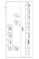
(撮像装置のブロック図)
図1は、本発明の実施形態に係る動画記録機能を備えた撮像装置としての電子スチルカメラの概略構成を示すブロック図である。
(Block diagram of imaging device)
FIG. 1 is a block diagram showing a schematic configuration of an electronic still camera as an imaging apparatus having a moving image recording function according to an embodiment of the present invention.
電子スチルカメラ100は、フォーカスレンズをその光軸に沿って移動させて焦点調節を行うことで被写体像を撮像素子に結像させる自動焦点調節装置を備える。
The electronic
101は、後述する撮像素子上に焦点を合わせるためのフォーカスレンズである。102はフォーカスレンズ101をその光軸に沿って移動させるフォーカスレンズ駆動モータである。103は被写体からの入射光を電気信号に変換する撮像素子である。
104は撮像素子103から出力されるアナログ信号をデジタル信号に変換するA/D変換器である。105はA/D変換器104から出力された画像データに所定の処理を施す画像処理プロセッサである。
106は撮影シーケンスなどシステムを制御するためのマイクロコントローラ(以下、「CPU」と呼ぶ。)である。107はCPU106で実行されるプログラムが記憶されているプログラムメモリである。108はCPU106がプログラムメモリ107に記憶されているプログラムに従って処理を行う際に必要な各種データを一時的に記憶するワークメモリである。
CPU106は、特定の被写体を含む焦点検出エリアに対応する被写体像を撮像素子103で検出して得られた焦点検出信号を用いて焦点調節を行う焦点調節手段の機能を備えている。
The
109は自動露出制御(以下、「AE」と呼ぶ。)やAF等の撮影準備を指示するための撮影準備指示スイッチ(以下、「SW1」と呼ぶ。)である。110は撮影準備指示スイッチ109の操作後、本露光及び記録動作等の撮影処理を指示するための撮影処理指示スイッチ(以下、「SW2」と呼ぶ。)である。111は動画の記録開始を指示する動画記録開始スイッチである。
112は画像を表示する画像表示部である。113は操作者が指やペン先などで触れる(タッチする)ことによりカメラに各種の動作や設定を指示するタッチパネルである。このタッチパネル113は画像表示部112に重ねて設置されており、指示手段としてのタッチパネル113のパネル上の位置と画像表示部112の表示面上の位置は一対一に対応しているものとする。
An
なお、以下の説明では画像表示部112に表示されている画像やアイコンに対応した、タッチパネル113上の位置をタッチすることを単に、画像にタッチする、アイコンにタッチすると表現する。
In the following description, touching a position on the
114は画像表示部112に表示されたメニュー項目の選択や焦点検出エリアの移動指示等に使用する十字スイッチである。115は画像処理プロセッサ105で処理された画像データから人物の顔を検出する被写体検出手段としての顔検出部である。116は画像処理プロセッサ105で処理された画像データから人物の顔以外の物体を検出する物体検出部である。117は記録する静止画及び動画のアスペクト比(画像の縦横比)を設定するアスペクト比設定部である。
次に、図1の電子スチルカメラ100の動作について説明する。なお、以下の説明において、記憶や判定などの処理は特に説明しない場合はプログラムメモリ107に記憶されたプログラムに基づいてCPU106が行うものとする。また、特に説明しない場合は、CPU106が演算結果や各種処理データをワークメモリ108に記憶するものとする。
Next, the operation of the electronic still
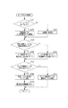
(撮影時の動作処理の流れを示すフローチャート)
図2は、図1の電子スチルカメラ100における撮影時の動作処理の流れを示すフローチャートである。
(Flow chart showing the flow of operation processing during shooting)
FIG. 2 is a flowchart showing a flow of operation processing at the time of shooting in the electronic
まず、S201では、撮像素子103の駆動モードをEVF用のものに設定する。ここで駆動モードとは、撮像素子の読み出しラインの選択や画素加算の方法、フレームレートの設定を指す。また、読み出しラインの選択の仕方によって、画像のアスペクト比が決まる。EVF用の駆動モードではアスペクト比はアスペクト比設定部117によって横4:縦3に設定されているものとする。
First, in S201, the drive mode of the
なお、既にEVF用の駆動モードに設定されている場合は改めて設定し直すことはしない。S202では撮影待機時の画像を画像表示部112に表示するためのEVF処理が行われる。このEVF処理では、AE、オートホワイトバランス(AWB)、表示用画像処理、画像表示部112への画像表示処理などが行われる。S203では後述する手順に従って撮影者によって指定した被写体への焦点検出エリアの設定を行う。
If the EVF drive mode has already been set, it is not set again. In S202, EVF processing for displaying an image at the time of shooting standby on the
S204ではS203で設定した焦点検出エリアを使って撮影前のAF動作を行う。この撮影前AF動作では、後述するS304またはS305またはS310またはS311で設定した焦点検出エリアから得られる画像信号から輝度信号の高域成分が最大になるレンズ位置を合焦位置とする方式を用いて焦点検出を行う。 In S204, an AF operation before photographing is performed using the focus detection area set in S203. In this pre-photographing AF operation, a method is used in which the lens position where the high frequency component of the luminance signal is maximized from the image signal obtained from the focus detection area set in S304, S305, S310, or S311 described later is used as the in-focus position. Perform focus detection.
S205では、SW1_109の状態を検出し、SW1_109がONであると判定した場合はS214へ進み、そうでなければS206へ進む。 In S205, the state of SW1_109 is detected. If it is determined that SW1_109 is ON, the process proceeds to S214. Otherwise, the process proceeds to S206.
S206では動画記録開始スイッチ111の状態を検出し、ONであればS207へ進み動画撮影を開始し、そうでなければS211へ進む。S207では撮像素子103の駆動モードを動画撮影用のものに設定する。動画撮影用の駆動モードではアスペクト比はアスペクト比設定部117によって横16:縦9に設定されているものとする。
In S206, the state of the moving image
なお、既に動画撮影用の駆動モードに設定されている場合は改めて設定し直すことはしない。S208ではS203と同様の、撮影者によって指定した被写体への焦点検出エリアの設定を行う。S209では後述する手順に従って動画撮影用の焦点検出エリア設定を行う。S210ではS209で設定した焦点検出エリアを使ってAFを行いながら動画撮影を行う。 Note that if the driving mode for moving image shooting has already been set, the setting is not performed again. In S208, as in S203, the focus detection area for the subject specified by the photographer is set. In step S209, the focus detection area for moving image shooting is set according to the procedure described later. In S210, moving image shooting is performed while performing AF using the focus detection area set in S209.
S211では動画撮影を停止する。S212では撮像素子103の駆動モードをEVF用のものに設定する。これはS201と同じ処理である。S213では後述する手順に従ってEVF用の焦点検出エリア設定を行う。
In S211, moving image shooting is stopped. In S212, the drive mode of the
S214では撮像素子103の駆動モードを本撮影用のAF用のものに設定する。本撮影用のAF用駆動モードではアスペクト比はアスペクト比設定部117によって横4:縦3に設定されているものとする。S215では後述する手順に従って本撮影用のAF用の焦点検出エリア設定を行う。S216ではS215で設定した焦点検出エリアを使ってAFを行う。
In S214, the driving mode of the
S217ではSW2_110の状態を検出し、ONであると判定した場合はS218へ進み、そうでなければ再びSW2_110の状態の検出を行う。S218では、撮像素子103への露光、読み出し、画像処理プロセッサ105による画像処理、図示しない記録媒体への記録などの撮影処理が行われる。
In S217, the state of SW2_110 is detected. If it is determined that the switch is ON, the process proceeds to S218. Otherwise, the state of SW2_110 is detected again. In S218, photographing processing such as exposure to the
(指定AF枠設定を説明するフローチャート)
図3は図2のS203における指定AF枠設定を説明するフローチャートである。まず、S301では、指示手段としてのタッチパネル113に撮影者がタッチしたかどうか判定し、タッチしていればS302へ、そうでなければS309へ進む。S302では、撮影者が後述するキャンセルアイコンにタッチしたかどうか判定し、タッチしていればS307へ、そうでなければS303へ進む。
(Flowchart explaining designated AF frame setting)
FIG. 3 is a flowchart for explaining the designated AF frame setting in S203 of FIG. First, in S301, it is determined whether or not the photographer has touched the
このキャンセルアイコンは図示しない初期化処理においてあらかじめ消去されているものとする。S303ではS301においてタッチされた位置に対応する画像表示部112の位置に、顔が表示されているかどうか判定し、表示されていればS304へ、そうでなければS305へ進む。
It is assumed that this cancel icon has been deleted in advance in an initialization process (not shown). In S303, it is determined whether or not a face is displayed at the position of the
この判定は、画像処理プロセッサ105で処理した画像から、顔検出部115によって検出された顔の位置とサイズに基づいて行う。
This determination is performed based on the position and size of the face detected by the
S304ではS301でタッチされた顔に相当する位置とサイズの焦点検出エリアを設定する。同時に画像表示部112にこの顔に対応する位置とサイズのAF枠を表示する。S305ではS301でタッチされた位置にある物体のサイズに合わせて、焦点検出エリアの位置とサイズを設定する。同時に画像表示部112にこの物体に対応する位置とサイズのAF枠を表示する。
In S304, a focus detection area having a position and size corresponding to the face touched in S301 is set. At the same time, an AF frame having a position and size corresponding to the face is displayed on the
この時の物体のサイズの検出は物体検出部116によって、画像信号の輝度や色、異なる時間で撮影された画像の相関によって行う。S306では画像表示部112にキャンセルアイコンを表示する。S312ではタッチフラグをTRUEにする。このタッチフラグとは、撮影者によるタッチパネル113へのタッチが行われた事を示すものである。
The size of the object at this time is detected by the
タッチフラグがTRUEの場合は被写体が指定されている状態を示し、FALSEの場合はキャンセルアイコンをタッチすることにより被写体の指定がキャンセルされている状態を示す。なおこのタッチフラグは図示しない初期化処理においてあらかじめFALSEに設定されているものとする。 When the touch flag is TRUE, the subject is designated, and when FALSE, the subject designation is canceled by touching the cancel icon. Note that this touch flag is set to FALSE in advance in an initialization process (not shown).
S307ではS304またはS305で設定した焦点検出エリアの位置とサイズを解除する。また、S304またはS305で表示したAF枠も消去する。S308ではS306で表示したキャンセルアイコンを消去する。S313ではタッチフラグをFALSEにする。 In S307, the position and size of the focus detection area set in S304 or S305 are canceled. Also, the AF frame displayed in S304 or S305 is deleted. In S308, the cancel icon displayed in S306 is deleted. In S313, the touch flag is set to FALSE.
S309では顔検出部115で顔が自動検出できたかどうか判定し、検出できたらS310へ、そうでなければS311へ進む。ここでの自動判定とは、撮影者によるタッチパネルへのタッチ指定なしに、カメラが自動的に顔を検出/判定することを指す。
In S309, it is determined whether or not the
S310ではカメラが自動で検出した顔に相当する位置とサイズの焦点検出エリアを設定する。同時に画像表示部112にこの顔に対応する位置とサイズのAF枠を表示する。S311ではカメラが自動で検出した位置にある物体のサイズに合わせて、焦点検出エリアの位置とサイズを設定する。この物体の自動検出は物体検出部116によって行う。同時に画像表示部112にこの物体に対応する位置とサイズのAF枠を表示する。
In step S310, a focus detection area having a position and size corresponding to the face automatically detected by the camera is set. At the same time, an AF frame having a position and size corresponding to the face is displayed on the
この図3の処理を繰り返し行うことによって、撮影者がタッチ指定した顔や物体が移動したりサイズが変わった場合でも、S304やS305でその都度焦点検出エリアを設定し直すことによって、顔や物体の位置とサイズに合った焦点検出エリアが設定できる。 By repeatedly performing the process of FIG. 3, even if the face or object touched by the photographer moves or changes size, the face or object can be reset by resetting the focus detection area each time in S304 or S305. A focus detection area that matches the position and size can be set.
なお、撮影者による顔又は物体の指定は、タッチパネル113の代わりに十字スイッチ114を操作することによって行ってもよい。
The photographer may specify the face or object by operating the
図3のように構成することによって、撮影者が所望の顔や物体にタッチまたは十字スイッチによって指定することによって、焦点検出エリアを設定することができる。さらにその指定の解除もできる。撮影者による指定がない時は、カメラが自動で検出した顔や物体に焦点検出エリアが設定される。 With the configuration shown in FIG. 3, the photographer can set a focus detection area by touching or specifying a desired face or object with a touch or a cross switch. Furthermore, the designation can be canceled. When there is no designation by the photographer, a focus detection area is set for a face or object automatically detected by the camera.
(動画撮影用焦点検出エリア設定)
図4は図2のS209における動画撮影用焦点検出エリア設定を説明するフローチャートである。まず、S401では図3のS312またはS313で設定したタッチフラグがTRUEかどうか判定し、TRUEであればS402へ、そうでなければS403へ進む。S402ではEVF処理において設定していた焦点検出エリア付近で顔検出を行う。
(Focus detection area setting for movie shooting)
FIG. 4 is a flowchart for explaining the focus detection area setting for moving image shooting in S209 of FIG. First, in S401, it is determined whether or not the touch flag set in S312 or S313 of FIG. 3 is TRUE. If TRUE, the process proceeds to S402, and if not, the process proceeds to S403. In S402, face detection is performed near the focus detection area set in the EVF process.
このようにする理由は、タッチによって被写体の指定がなされている場合は指定された顔を検出し続けるようにするためである。S403では全画面で顔検出を行う。この場合はタッチによって被写体の指定がなされていないので、全画面の中からカメラが自動的に顔を検出する。 The reason for doing this is to keep detecting the specified face when the subject is specified by touch. In S403, face detection is performed on the entire screen. In this case, since the subject is not designated by touch, the camera automatically detects the face from the entire screen.
S404では撮像素子103の現在の駆動モード、すなわち図2のS207で設定した動画撮影用の駆動モードにおいて、顔検出部115から顔検出結果が出力されたかどうか判定し、出力されていればS405へ、そうでなければS406へ進む。
In S404, it is determined whether or not a face detection result is output from the
S405では焦点検出エリアを、動画撮影用駆動モードにおいて検出された顔位置とサイズに決める。 In S405, the focus detection area is determined by the face position and size detected in the moving image shooting drive mode.
S406では焦点検出エリアを、EVF処理において設定していた位置とサイズに決める。 In S406, the focus detection area is determined to the position and size set in the EVF process.
S404からS406のような処理を行う理由は、撮像素子103の駆動モードを切り替えた後に、その駆動モードで露光/読み出しされた画像データを画像処理プロセッサ105で処理する。
The reason for performing the processes from S404 to S406 is that the
さらに顔検出部115で顔検出を行うために、駆動モード切り替え直後はすぐに顔検出結果が出ないからである。
Further, since face detection is performed by the
従って、駆動モードを切り替えてからしばらく時間が経過して顔検出結果が出力されればその結果に応じて焦点検出エリアを決め、そうでなければEVF処理において設定していた位置とサイズに焦点検出エリアを決める。 Therefore, if a face detection result is output after a while after switching the driving mode, a focus detection area is determined according to the result, otherwise focus detection is performed at the position and size set in the EVF processing. Decide the area.
なお、EVF処理時の焦点検出エリアの位置とサイズが変化した際にその履歴を取っておき、S406における焦点検出エリアの設定を履歴に基づいて行っても良い。この履歴から、焦点検出エリアの位置が移動していると判定された場合には、次の移動位置を予測して設定する。さらにS404で顔検出結果が出力されるまで、履歴に基づいて次の移動位置を更新し、更新結果に基づいて焦点検出エリアの位置を設定する。焦点検出エリアのサイズについても同様である。その際、後述するS505において設定する焦点検出エリアの位置とサイズの履歴を取っておく。 Note that a history may be saved when the position and size of the focus detection area during EVF processing change, and the focus detection area setting in S406 may be performed based on the history. If it is determined from this history that the position of the focus detection area is moving, the next moving position is predicted and set. Further, the next movement position is updated based on the history until the face detection result is output in S404, and the position of the focus detection area is set based on the update result. The same applies to the size of the focus detection area. At that time, a history of the position and size of the focus detection area set in S505 described later is kept.
S407ではS405又はS406で決めた焦点検出エリアが動画撮影用の駆動モードの画角に収まるかどうか判定し、収まればS408へ、そうでなければS410へ進む。S408では焦点検出エリアをS405又はS406で決めた位置とサイズに設定する。 In S407, it is determined whether or not the focus detection area determined in S405 or S406 falls within the angle of view of the driving mode for moving image shooting. If so, the process proceeds to S408, and if not, the process proceeds to S410. In S408, the focus detection area is set to the position and size determined in S405 or S406.
S409では、被写体検出手段としての顔検出部115で顔を検出する際の信頼性判定閾値をR1に設定する。この信頼性判定閾値は図示しない初期化処理においてあらかじめR0に設定されているものとする。R0とR1の関係は式(1)のようになっている。
R0<R1・・・・(1)
つまり、S409では顔判定を行う際の信頼性判定閾値をEVF処理時のものよりも厳しくする。この理由は次のとおりである。S405又はS406で決めた位置に焦点検出エリアを設定する場合は、図3で説明したように撮影者がタッチパネル113をタッチして指定した被写体位置に焦点検出エリアが設定される場合がある。
In step S409, the reliability determination threshold value when the face is detected by the
R0 <R1 (1)
That is, in S409, the reliability determination threshold for performing the face determination is made stricter than that for EVF processing. The reason for this is as follows. When the focus detection area is set at the position determined in S405 or S406, the focus detection area may be set at the subject position designated by the photographer touching the
この場合は、撮影者が意図した被写体に焦点検出エリアを設定し続けた方が良い。そのため焦点検出エリアを設定するために使用する顔検出結果も、撮影者が意図した顔が検出されるようにした方が良い。 In this case, it is better to continue setting the focus detection area for the subject intended by the photographer. Therefore, it is better that the face detection result used for setting the focus detection area also detects the face intended by the photographer.
しかし、顔信頼性判定閾値を緩く設定すると、誤検出が起こりやすくなり意図しない顔が検出されてしまう。動画撮影中にこのようなことが起こると、撮影者が意図しない顔にピントが合った画像が記録されてしまうので不都合である。これを防ぐために顔信頼性判定閾値を厳しくして撮影者が意図した顔が検出され続けるようにする。 However, if the face reliability determination threshold is set loosely, erroneous detection is likely to occur, and an unintended face is detected. If this happens during moving image shooting, it is inconvenient because an image focused on the face not intended by the photographer is recorded. In order to prevent this, the face reliability determination threshold is tightened so that the face intended by the photographer is continuously detected.
顔信頼性の判定は、検出された顔の大きさを判定して行う。この時の信頼性判定閾値は顔の大きさに対する閾値となる。またはテンプレートマッチングを用いて、目、鼻、口、輪郭等の特徴的な部位についてテンプレートとの一致度を判定して顔信頼性の判定を行う。この場合の信頼性判定閾値は一致度に対する閾値となる。 The face reliability is determined by determining the size of the detected face. The reliability determination threshold at this time is a threshold for the face size. Alternatively, using template matching, the degree of coincidence with the template is determined for characteristic parts such as eyes, nose, mouth, and contour, and face reliability is determined. In this case, the reliability determination threshold is a threshold for the degree of coincidence.
S410では、焦点検出エリアをS405又はS406で決めた位置に最も近い位置で、かつ動画用駆動モードの画角内に収まる位置、つまり、動画用駆動モードでの画面端に設定する。サイズはS405又はS406で決めたものに設定する。 In S410, the focus detection area is set to the position closest to the position determined in S405 or S406 and within the angle of view of the moving image driving mode, that is, the screen edge in the moving image driving mode. The size is set as determined in S405 or S406.
動画撮影待機中であるEVF処理において、撮像素子103の駆動モードのアスペクト比は4:3であり、動画撮影中のそれは16:9である。そのため動画撮影中の方が上下に狭い画角となる。ここで、EVF処理中に指定、または、設定されていた焦点検出エリアの位置が画面の上下方向の端にあると、動画撮影時には画角外となってしまう。
In the EVF process during the moving image shooting standby, the aspect ratio of the driving mode of the
そのため、S407からS410のように動画用の駆動モードの画角内に収まるかどうか判定し、画角内に収まらなければ動画用駆動モードでの画面端に焦点検出エリアを設定する。 Therefore, as in S407 to S410, it is determined whether or not it falls within the field angle of the moving image driving mode. If it does not fall within the field angle, the focus detection area is set at the screen edge in the moving image driving mode.
なお、図4では顔の検出結果について説明したが、物体検出部116による物体検出結果を用いる場合も同様の処理を行う。
Although the face detection result has been described with reference to FIG. 4, the same processing is performed when the object detection result by the
(EVF用焦点検出エリア設定を説明するフローチャート)
図5は図2のS213におけるEVF用焦点検出エリア設定を説明するフローチャートである。まず、S501では図3のS312またはS313で設定したタッチフラグがTRUEかどうか判定し、TRUEであればS502へ、そうでなければS503へ進む。S502では動画撮影処理において設定していた焦点検出エリア付近で顔検出を行う。
(Flowchart for explaining EVF focus detection area setting)
FIG. 5 is a flowchart for explaining EVF focus detection area setting in S213 of FIG. First, in S501, it is determined whether or not the touch flag set in S312 or S313 in FIG. 3 is TRUE. In S502, face detection is performed near the focus detection area set in the moving image shooting process.
このようにする理由は、タッチによって被写体の指定がなされている場合は指定された顔を検出し続けるようにするためである。S503では全画面で顔検出を行う。この場合はタッチによって被写体の指定がなされていないので、全画面の中からカメラが自動的に顔を検出する。 The reason for doing this is to keep detecting the specified face when the subject is specified by touch. In step S503, face detection is performed on the entire screen. In this case, since the subject is not designated by touch, the camera automatically detects the face from the entire screen.
S504では撮像素子103の現在の駆動モード、すなわち図2のS212で設定したEVF用の駆動モードにおいて、顔検出部115から顔検出結果が出力されたかどうか判定し、出力されていればS505へ、そうでなければS506へ進む。
In S504, it is determined whether or not the face detection result is output from the
S505では焦点検出エリアを、EVF用駆動モードにおいて検出された顔位置とサイズに決める。S506では焦点検出エリアを、動画撮影処理において設定していた位置とサイズに決める。S504からS506のような処理を行う理由は、図4のS404からS406での処理の説明と同じである。 In S505, the focus detection area is determined by the face position and size detected in the EVF drive mode. In S506, the focus detection area is determined to be the position and size set in the moving image shooting process. The reason for performing the processing from S504 to S506 is the same as the description of the processing from S404 to S406 in FIG.
動画記録中の焦点検出エリアの位置とサイズを設定した時と同様に、動画撮影中の焦点検出エリアの位置とサイズの履歴を取っておき、その履歴に基づいてEVF処理における焦点検出エリアの位置とサイズを決めても良い。その際、前述したS405において設定した焦点検出エリアの位置とサイズの履歴を取っておく。 As in the case of setting the position and size of the focus detection area during movie recording, a history of the position and size of the focus detection area during movie shooting is saved, and the position and size of the focus detection area in EVF processing based on the history. You may decide. At that time, a history of the position and size of the focus detection area set in S405 described above is kept.
S507ではS505又はS506で決めた焦点検出エリアがEVF用の駆動モードの画角に収まるかどうか判定し、収まればS508へ、そうでなければS510へ進む。S508では焦点検出エリアをS505又はS506で決めた位置とサイズに設定する。 In S507, it is determined whether or not the focus detection area determined in S505 or S506 falls within the angle of view of the drive mode for EVF. If so, the process proceeds to S508, and if not, the process proceeds to S510. In S508, the focus detection area is set to the position and size determined in S505 or S506.
S509では顔検出部115で顔を検出する際の信頼性判定閾値をR0に設定する。つまり、S509では顔判定を行う際の信頼性判定閾値を動画撮影時のものよりも緩くする。EVF処理、すなわち撮影待機中は多少の顔の誤検出があっても記録には残らないので、新たな顔の検出のしやすさを優先してこの様にする。
In S509, the reliability determination threshold value when the
S510では焦点検出エリアをS505又はS506で決めた位置に最も近い位置で、かつ動画用駆動モードの画角内に収まる位置、つまりEVF用駆動モードでの画面端に設定する。サイズはS505又はS506で決めたものに設定する。 In S510, the focus detection area is set to the position closest to the position determined in S505 or S506 and within the angle of view of the moving image driving mode, that is, the screen edge in the EVF driving mode. The size is set as determined in S505 or S506.
(本撮影用焦点検出エリア設定を説明するフローチャート)
図6は図2のS215における本撮影用焦点検出エリア設定を説明するフローチャートである。まずS601では焦点検出エリアを、EVF処理において設定していた位置とサイズに決める。S602では焦点検出エリアをS601で決めた位置とサイズに設定する。撮像素子103のEVF用の駆動モードと本撮影用AF用の駆動モードにおけるアスペクト比は共に4:3なので、EVF処理における焦点検出エリアの設定位置とサイズを、本撮影用AF用の駆動モードでもそのまま使う。
(Flowchart explaining focus detection area setting for actual photographing)
FIG. 6 is a flowchart for explaining the focus detection area setting for actual photographing in S215 of FIG. First, in S601, the focus detection area is determined to the position and size set in the EVF process. In step S602, the focus detection area is set to the position and size determined in step S601. Since the aspect ratios in the EVF driving mode and the main shooting AF driving mode of the
本実施例では、第1の撮影記録モード時に指示手段によって焦点検出エリアの指示がなされた後に第2の撮影記録モードが開始された場合を考える。 In this embodiment, a case is considered in which the second shooting / recording mode is started after the focus detection area is instructed by the instruction unit in the first shooting / recording mode.
その場合、第2の撮影記録モードとなった後に被写体検出手段により特定の被写体が検出されるまで、第1の撮影記録モード時の焦点検出エリアの位置に基いて第2の撮影記録モードの焦点検出エリアの位置を決定する。 In this case, the focus of the second shooting / recording mode is based on the position of the focus detection area in the first shooting / recording mode until a specific subject is detected by the subject detection means after the second shooting / recording mode is set. Determine the position of the detection area.
より具体的に、動画記録が開始される以前に焦点検出エリアの指示がなされた後に動画記録が開始された場合、動画記録が開始された後に特定の被写体が検出されないとき、動画記録が開始される以前に指示された焦点検出エリアの位置を維持する。 More specifically, if movie recording is started after the focus detection area is instructed before movie recording is started, movie recording is started when a specific subject is not detected after movie recording is started. The position of the focus detection area indicated before is maintained.
このように、動画撮影待機時に撮影者によって指定された被写体位置に焦点検出エリアを設定し、動画記録時は動画撮影待機時に指定された被写体の位置に焦点検出エリアを設定し続けることによって撮影者に所望の被写体に合焦し続けることができる。 As described above, the focus detection area is set at the subject position designated by the photographer during the movie shooting standby, and the focus detection area is continuously set at the subject position designated during the movie shooting standby during the movie recording. It is possible to continue focusing on a desired subject.
その際に動画記録開始直後で、撮像素子103の駆動モードが切り替わった直後のため顔や物体の検出結果が得られない場合は、待機中の焦点検出エリアの位置とサイズを引き継ぐことによって、焦点検出エリアが設定できない空白期間が生じることがない。
At that time, if the detection result of the face or object cannot be obtained immediately after the start of moving image recording and immediately after the drive mode of the
さらに動画待機中と記録中の撮像素子103のアスペクト比が異なるために、待機中と同じ位置に焦点検出エリアを設定できない場合には、位置をずらすことによって設定不能な状態を回避することができる。
Further, when the focus detection area cannot be set at the same position as in standby because the aspect ratio of the
また、動画記録が開始される以前に指示手段によって指示された焦点検出エリアが動画記録が開始された後の画角内に収まらない場合、動画記録が開始される以前に指示手段によって指示された焦点検出エリアを画角内に移動させる。 In addition, if the focus detection area indicated by the instruction unit before starting the moving image recording does not fall within the angle of view after starting the moving image recording, the instruction unit instructed before starting the moving image recording. The focus detection area is moved within the angle of view.
以上、本発明をその好適な実施形態に基づいて詳述してきたが、本発明はこれら特定の実施形態に限られるものではなく、この発明の要旨を逸脱しない範囲の様々な形態も本発明に含まれる。上述の実施形態の一部を適宜組み合わせてもよい。 Although the present invention has been described in detail based on preferred embodiments thereof, the present invention is not limited to these specific embodiments, and various forms within the scope of the present invention are also included in the present invention. included. A part of the above-described embodiments may be appropriately combined.
また、上述の実施形態の機能を実現するソフトウェアのプログラムを、記録媒体から直接、或いは有線/無線通信を用いてプログラムを実行可能なコンピュータを有するシステム又は装置に供給し、そのプログラムを実行する場合も本発明に含む。 Also, when a software program that realizes the functions of the above-described embodiments is supplied from a recording medium directly to a system or apparatus having a computer that can execute the program using wired / wireless communication, and the program is executed Are also included in the present invention.
従って、本発明の機能処理をコンピュータで実現するために、該コンピュータに供給、インストールされるプログラムコード自体も本発明を実現するものである。つまり、本発明の機能処理を実現するためのコンピュータプログラム自体も本発明に含まれる。 Accordingly, the program code itself supplied and installed in the computer in order to implement the functional processing of the present invention by the computer also realizes the present invention. That is, the computer program itself for realizing the functional processing of the present invention is also included in the present invention.
その場合、プログラムの機能を有していれば、オブジェクトコード、インタプリタにより実行されるプログラム、OSに供給するスクリプトデータ等、プログラムの形態を問わない。 In this case, the program may be in any form as long as it has a program function, such as an object code, a program executed by an interpreter, or script data supplied to the OS.
プログラムを供給するための記録媒体としては、例えば、ハードディスク、磁気テープ等の磁気記録媒体、光/光磁気記憶媒体、不揮発性の半導体メモリでもよい。 As a recording medium for supplying the program, for example, a magnetic recording medium such as a hard disk or a magnetic tape, an optical / magneto-optical storage medium, or a nonvolatile semiconductor memory may be used.
また、プログラムの供給方法としては、コンピュータネットワーク上のサーバに本発明を形成するコンピュータプログラムを記憶し、接続のあったクライアントコンピュータがコンピュータプログラムをダウンロードしてプログラムするような方法も考えられる。 As a program supply method, a computer program that forms the present invention is stored in a server on a computer network, and a connected client computer downloads and programs the computer program.
100 電子スチルカメラ
101 フォーカスレンズ
102 フォーカスレンズ駆動モータ
103 撮像素子
104 A/D変換器
105 画像処理プロセッサ
106 マイクロコントローラ(CPU)
107 プログラムメモリ
108 ワークメモリ
109 撮影準備指示スイッチ(SW1)
110 撮影処理指示スイッチ(SW2)
111 動画記録開始スイッチ
112 画像表示部
113 タッチパネル
114 十字スイッチ
115 顔検出部
116 物体検出部
117 アスペクト比設定部
DESCRIPTION OF
107
110 Shooting processing instruction switch (SW2)
111 moving image
Claims (11)
焦点検出エリアの位置の指示を受け付ける受付手段と、
前記被写体検出手段による検出結果、または前記受付手段による受付結果に基づいて焦点検出エリアを設定する設定手段と、
前記焦点検出エリアの焦点検出信号に応じて合焦状態を調節する焦点調節手段と、を有し、
撮影待機の際に画像を前記撮像素子から読み出す第1の駆動モードと、動画撮影の際に前記撮影待機の際の画像とはアスペクト比が異なる画像を前記撮像素子から読み出す第2の駆動モードと、を備えた撮像装置であって、
前記被写体検出手段は、前記第1の駆動モードから前記第2の駆動モードとなったときの特定の被写体の検出範囲を、前記受付手段により焦点検出エリアの位置の指示を受け付けたことを示す履歴がある場合に前記履歴がない場合よりも狭くし、
前記設定手段は、前記第1の駆動モードから前記第2の駆動モードとなってから前記被写体検出手段による特定の被写体の検出結果が出ない間は、前記第1の駆動モードにおいて設定された焦点検出エリアの位置に基づいて、焦点検出エリアを設定することを特徴とする撮像装置。 Subject detection means for detecting a specific subject from the image read from the image sensor;
Receiving means for receiving an instruction of the position of the focus detection area;
Setting means for setting a focus detection area based on the detection result by the subject detection means or the reception result by the reception means;
Focus adjusting means for adjusting the in-focus state in accordance with a focus detection signal of the focus detection area,
A first drive mode in which an image is read from the image pickup device during shooting standby, and a second drive mode in which an image having a different aspect ratio from the image in the shooting standby is read from the image pickup device during moving image shooting. An imaging device comprising:
History indicating that the subject detection means has received a specific subject detection range when the first drive mode is changed to the second drive mode, and that the reception means has received an instruction of a position of a focus detection area. If there is, make it narrower than if there is no history,
The setting means sets the focus set in the first drive mode until the detection result of the specific subject by the subject detection means is not obtained after the first drive mode is changed to the second drive mode. An imaging apparatus, wherein a focus detection area is set based on a position of the detection area.
前記第2の駆動モードの前記閾値は、前記第1の駆動モードの閾値よりも大きいことを特徴とする請求項1または2に記載の撮像装置。 The subject detection means compares the reliability of the specific subject with a threshold value, and determines that the specific subject has been detected when the reliability is higher than the threshold value,
The imaging apparatus according to claim 1, wherein the threshold value of the second drive mode is larger than a threshold value of the first drive mode.
焦点検出エリアの位置の指示を受け付ける受付工程と、
前記被写体検出工程による検出結果、または前記受付工程による受付結果に基づいて焦点検出エリアを設定する設定工程と、
前記焦点検出エリアの焦点検出信号に応じて合焦状態を調節する焦点調節工程と、を有し、
撮影待機の際に画像を前記撮像素子から読み出す第1の駆動モードと、動画撮影の際に前記撮影待機の際の画像とはアスペクト比が異なる画像を前記撮像素子から読み出す第2の駆動モードと、を備えた撮像方法であって、
前記被写体検出工程では、前記第1の駆動モードから前記第2の駆動モードとなったときの特定の被写体の検出範囲を、前記受付工程で焦点検出エリアの位置の指示を受け付けたことを示す履歴がある場合に前記履歴がない場合よりも狭くし、
前記設定工程では、前記第1の駆動モードから前記第2の駆動モードとなってから前記被写体検出工程による特定の被写体の検出結果が出ない間は、前記第1の駆動モードにおいて設定された焦点検出エリアの位置に基づいて、焦点検出エリアを設定することを特徴とする撮像方法。 A subject detection step of detecting a specific subject from an image read from the image sensor;
A reception step of receiving an indication of the position of the focal point detection area,
A setting step of setting a focus detection area based on the detection result of the subject detection step or the reception result of the reception step;
A focus adjustment step of adjusting a focus state according to a focus detection signal of the focus detection area,
A first drive mode in which an image is read from the image pickup device during shooting standby, and a second drive mode in which an image having a different aspect ratio from the image in the shooting standby is read from the image pickup device during moving image shooting. An imaging method comprising:
In the subject detection step, a history indicating that a detection range of a specific subject when the first drive mode is changed to the second drive mode is received, and an instruction of a position of a focus detection area is received in the reception step. If there is, make it narrower than if there is no history,
In the setting step, the focus set in the first drive mode is not obtained after the detection result of the specific subject in the subject detection step is not obtained after the first drive mode is changed to the second drive mode. An imaging method, wherein a focus detection area is set based on a position of the detection area.
焦点検出エリアの位置の指示を受け付ける受付手段と、
前記被写体検出手段による検出結果、または前記受付手段による受付結果に基づいて焦点検出エリアを設定する設定手段と、
前記焦点検出エリアの焦点検出信号に応じて合焦状態を調節する焦点調節手段と、を有し、
撮影待機の際に画像を前記撮像素子から読み出す第1の駆動モードと、動画撮影の際に前記撮影待機の際の画像とはアスペクト比が異なる画像を前記撮像素子から読み出す第2の駆動モードと、を備えた撮像装置であって、
前記被写体検出手段は、前記第2の駆動モードから前記第1の駆動モードとなったときの特定の被写体の検出範囲を、前記受付手段により焦点検出エリアの位置の指示を受け付けたことを示す履歴がある場合に前記履歴がない場合よりも狭くし、
前記設定手段は、前記第2の駆動モードから前記第1の駆動モードとなってから前記被写体検出手段による特定の被写体の検出結果が出ない間は、前記第2の駆動モードにおいて設定された焦点検出エリアの位置に基づいて焦点検出エリアを設定することを特徴とする撮像装置。 Subject detection means for detecting a specific subject from the image read from the image sensor;
Receiving means for receiving an instruction of the position of the focus detection area;
Setting means for setting a focus detection area based on the detection result by the subject detection means or the reception result by the reception means;
Focus adjusting means for adjusting the in-focus state in accordance with a focus detection signal of the focus detection area,
A first drive mode in which an image is read from the image pickup device during shooting standby, and a second drive mode in which an image having a different aspect ratio from the image in the shooting standby is read from the image pickup device during moving image shooting. An imaging device comprising:
A history indicating that the subject detection unit has received a detection range of a specific subject when the second drive mode is changed to the first drive mode, and has received an instruction for a position of a focus detection area by the reception unit. If there is, make it narrower than if there is no history,
The setting means has a focus set in the second drive mode until a detection result of a specific subject is not obtained by the subject detection means after the second drive mode is changed to the first drive mode. An imaging apparatus, wherein a focus detection area is set based on a position of the detection area.
焦点検出エリアの位置の指示を受け付ける受付工程と、
前記被写体検出工程による検出結果、または前記受付工程による受付結果に基づいて焦点検出エリアを設定する設定工程と、
前記焦点検出エリアの焦点検出信号に応じて合焦状態を調節する焦点調節工程と、を有し、
撮影待機の際に画像を前記撮像素子から読み出す第1の駆動モードと、動画撮影の際に前記撮影待機の際の画像とはアスペクト比が異なる画像を前記撮像素子から読み出す第2の駆動モードと、を備えた撮像方法であって、
前記被写体検出工程では、前記第2の駆動モードから前記第1の駆動モードとなったときの特定の被写体の検出範囲を、前記受付工程で焦点検出エリアの位置の指示を受け付けたことを示す履歴がある場合に前記履歴がない場合よりも狭くし、
前記設定工程では、前記第2の駆動モードから前記第1の駆動モードとなってから前記被写体検出工程による特定の被写体の検出結果が出ない間は、前記第2の駆動モードにおいて設定された焦点検出エリアの位置に基づいて、焦点検出エリアを設定することを特徴とする撮像方法。 A subject detection step of detecting a specific subject from an image read from the image sensor;
A reception step of receiving an indication of the position of the focal point detection area,
A setting step of setting a focus detection area based on the detection result of the subject detection step or the reception result of the reception step;
A focus adjustment step of adjusting a focus state according to a focus detection signal of the focus detection area,
A first drive mode in which an image is read from the image pickup device during shooting standby, and a second drive mode in which an image having a different aspect ratio from the image in the shooting standby is read from the image pickup device during moving image shooting. An imaging method comprising:
In the subject detection step, a history indicating that a detection range of a specific subject when the second drive mode is changed to the first drive mode is received and an instruction for a position of a focus detection area is received in the reception step. If there is, make it narrower than if there is no history,
In the setting step, the focus set in the second drive mode is not obtained after the detection result of the specific subject in the subject detection step is not obtained after the second drive mode is changed to the first drive mode. An imaging method, wherein a focus detection area is set based on a position of the detection area.
Priority Applications (3)
| Application Number | Priority Date | Filing Date | Title |
|---|---|---|---|
| JP2014104494A JP6465566B2 (en) | 2013-08-21 | 2014-05-20 | Imaging apparatus and imaging method |
| US14/461,259 US9264603B2 (en) | 2013-08-21 | 2014-08-15 | Imaging apparatus and imaging method |
| CN201410412065.7A CN104427244B (en) | 2013-08-21 | 2014-08-20 | Picture pick-up device and image capture method |
Applications Claiming Priority (3)
| Application Number | Priority Date | Filing Date | Title |
|---|---|---|---|
| JP2013171639 | 2013-08-21 | ||
| JP2013171639 | 2013-08-21 | ||
| JP2014104494A JP6465566B2 (en) | 2013-08-21 | 2014-05-20 | Imaging apparatus and imaging method |
Publications (3)
| Publication Number | Publication Date |
|---|---|
| JP2015062052A JP2015062052A (en) | 2015-04-02 |
| JP2015062052A5 JP2015062052A5 (en) | 2017-06-22 |
| JP6465566B2 true JP6465566B2 (en) | 2019-02-06 |
Family
ID=52480023
Family Applications (1)
| Application Number | Title | Priority Date | Filing Date |
|---|---|---|---|
| JP2014104494A Active JP6465566B2 (en) | 2013-08-21 | 2014-05-20 | Imaging apparatus and imaging method |
Country Status (3)
| Country | Link |
|---|---|
| US (1) | US9264603B2 (en) |
| JP (1) | JP6465566B2 (en) |
| CN (1) | CN104427244B (en) |
Families Citing this family (3)
| Publication number | Priority date | Publication date | Assignee | Title |
|---|---|---|---|---|
| CN105049732B (en) * | 2015-08-27 | 2018-05-29 | 广东欧珀移动通信有限公司 | A kind of camera shooting head adjusting method and user terminal |
| JP6777993B2 (en) | 2016-01-29 | 2020-10-28 | キヤノン株式会社 | Image processing equipment, image processing methods and programs |
| JP6393296B2 (en) * | 2016-08-30 | 2018-09-19 | キヤノン株式会社 | IMAGING DEVICE AND ITS CONTROL METHOD, IMAGING CONTROL DEVICE, PROGRAM, AND STORAGE MEDIUM |
Family Cites Families (14)
| Publication number | Priority date | Publication date | Assignee | Title |
|---|---|---|---|---|
| JP4284998B2 (en) | 2002-12-26 | 2009-06-24 | ソニー株式会社 | Imaging apparatus and method, and program |
| JP4367955B2 (en) * | 2005-04-21 | 2009-11-18 | キヤノン株式会社 | Imaging apparatus and control method thereof |
| US8525892B2 (en) * | 2005-04-21 | 2013-09-03 | Canon Kabushiki Kaisha | Imaging apparatus and control method therefor |
| JP2007049222A (en) * | 2005-08-05 | 2007-02-22 | Canon Inc | Imaging apparatus and method |
| JP5263565B2 (en) * | 2006-10-12 | 2013-08-14 | ソニー株式会社 | Image processing apparatus, image processing method, and program |
| DK2151569T3 (en) * | 2008-08-06 | 2012-10-29 | Waertsilae Switzerland Ltd | Device for extracting an exhaust gas partial flow and combustion engine with this device |
| JP5419585B2 (en) * | 2009-08-04 | 2014-02-19 | キヤノン株式会社 | Image processing apparatus, image processing method, and program |
| JP5550304B2 (en) * | 2009-10-19 | 2014-07-16 | キヤノン株式会社 | Imaging device |
| JP5448726B2 (en) * | 2009-11-05 | 2014-03-19 | キヤノン株式会社 | Image shooting device |
| JP5603671B2 (en) * | 2010-06-22 | 2014-10-08 | オリンパスイメージング株式会社 | Electronic device, imaging method, and image conversion program |
| TWI433530B (en) * | 2010-11-01 | 2014-04-01 | Ind Tech Res Inst | Camera system and image-shooting method with guide for taking stereo photo and method for automatically adjusting stereo photo |
| JP5882593B2 (en) * | 2011-03-14 | 2016-03-09 | キヤノン株式会社 | Imaging device |
| JP2014013986A (en) * | 2012-07-04 | 2014-01-23 | Canon Inc | Imaging device |
| JP5423851B2 (en) * | 2012-07-23 | 2014-02-19 | 株式会社ニコン | Electronic camera |
-
2014
- 2014-05-20 JP JP2014104494A patent/JP6465566B2/en active Active
- 2014-08-15 US US14/461,259 patent/US9264603B2/en not_active Expired - Fee Related
- 2014-08-20 CN CN201410412065.7A patent/CN104427244B/en active Active
Also Published As
| Publication number | Publication date |
|---|---|
| CN104427244B (en) | 2019-05-03 |
| US20150054976A1 (en) | 2015-02-26 |
| CN104427244A (en) | 2015-03-18 |
| JP2015062052A (en) | 2015-04-02 |
| US9264603B2 (en) | 2016-02-16 |
Similar Documents
| Publication | Publication Date | Title |
|---|---|---|
| US10623647B2 (en) | Image capturing apparatus and control method for changing a setting based on a touch operation on a display | |
| JP5820181B2 (en) | Imaging system and control method thereof, display control apparatus and control method thereof, program, and storage medium | |
| US10419683B2 (en) | Zoom control device, imaging apparatus, control method of zoom control device, and recording medium | |
| JP6757268B2 (en) | Imaging device and its control method | |
| US10715719B2 (en) | Image capturing apparatus and control method thereof | |
| US10397482B2 (en) | Imaging control apparatus and method for controlling the same | |
| JP2018125612A5 (en) | ||
| KR20100055938A (en) | Method and apparatus for displaying scene information, and digital photographing apparatus thereof | |
| JP2018133674A (en) | Imaging apparatus and control method of the same | |
| JP2006033440A (en) | Digital camera | |
| JP7418104B2 (en) | Image processing device and method of controlling the image processing device | |
| JP2019054378A (en) | Imaging apparatus and control method thereof, and program | |
| JP6465566B2 (en) | Imaging apparatus and imaging method | |
| JP2012222387A (en) | Imaging apparatus | |
| CN113364945A (en) | Electronic apparatus, control method, and computer-readable medium | |
| US10785405B2 (en) | Electronic device, control method, and storage medium | |
| JP6701027B2 (en) | Imaging device, control method thereof, and program | |
| US11526264B2 (en) | Electronic apparatus for enlarging or reducing display object, method of controlling electronic apparatus, and non-transitory computer readable medium | |
| WO2020129620A1 (en) | Imaging control device, imaging device, and imaging control method | |
| JP2006033438A (en) | Digital camera | |
| JP2018085570A (en) | Imaging apparatus, imaging method, and program | |
| JP2019165299A (en) | Display control device, control method thereof, and program | |
| JP7446913B2 (en) | Electronic devices, control methods for electronic devices, and programs | |
| US11330187B2 (en) | Electronic apparatus, method of controlling electronic apparatus, and storage medium | |
| JP7071197B2 (en) | Imaging device and its control method |
Legal Events
| Date | Code | Title | Description |
|---|---|---|---|
| A521 | Request for written amendment filed |
Free format text: JAPANESE INTERMEDIATE CODE: A523 Effective date: 20170511 |
|
| A621 | Written request for application examination |
Free format text: JAPANESE INTERMEDIATE CODE: A621 Effective date: 20170511 |
|
| A977 | Report on retrieval |
Free format text: JAPANESE INTERMEDIATE CODE: A971007 Effective date: 20171222 |
|
| A131 | Notification of reasons for refusal |
Free format text: JAPANESE INTERMEDIATE CODE: A131 Effective date: 20180109 |
|
| A521 | Request for written amendment filed |
Free format text: JAPANESE INTERMEDIATE CODE: A523 Effective date: 20180309 |
|
| A131 | Notification of reasons for refusal |
Free format text: JAPANESE INTERMEDIATE CODE: A131 Effective date: 20180821 |
|
| A521 | Request for written amendment filed |
Free format text: JAPANESE INTERMEDIATE CODE: A523 Effective date: 20181017 |
|
| TRDD | Decision of grant or rejection written | ||
| A01 | Written decision to grant a patent or to grant a registration (utility model) |
Free format text: JAPANESE INTERMEDIATE CODE: A01 Effective date: 20181211 |
|
| A61 | First payment of annual fees (during grant procedure) |
Free format text: JAPANESE INTERMEDIATE CODE: A61 Effective date: 20190108 |
|
| R151 | Written notification of patent or utility model registration |
Ref document number: 6465566 Country of ref document: JP Free format text: JAPANESE INTERMEDIATE CODE: R151 |