JP7370460B2 - Mobile termination information distribution for multiple USIM UEs - Google Patents
Mobile termination information distribution for multiple USIM UEs Download PDFInfo
- Publication number
- JP7370460B2 JP7370460B2 JP2022519611A JP2022519611A JP7370460B2 JP 7370460 B2 JP7370460 B2 JP 7370460B2 JP 2022519611 A JP2022519611 A JP 2022519611A JP 2022519611 A JP2022519611 A JP 2022519611A JP 7370460 B2 JP7370460 B2 JP 7370460B2
- Authority
- JP
- Japan
- Prior art keywords
- plmn
- node
- network
- n3iwf
- data
- Prior art date
- Legal status (The legal status is an assumption and is not a legal conclusion. Google has not performed a legal analysis and makes no representation as to the accuracy of the status listed.)
- Active
Links
Images


Classifications
-
- H—ELECTRICITY
- H04—ELECTRIC COMMUNICATION TECHNIQUE
- H04W—WIRELESS COMMUNICATION NETWORKS
- H04W76/00—Connection management
- H04W76/10—Connection setup
- H04W76/15—Setup of multiple wireless link connections
- H04W76/16—Involving different core network technologies, e.g. a packet-switched [PS] bearer in combination with a circuit-switched [CS] bearer
-
- H—ELECTRICITY
- H04—ELECTRIC COMMUNICATION TECHNIQUE
- H04W—WIRELESS COMMUNICATION NETWORKS
- H04W60/00—Affiliation to network, e.g. registration; Terminating affiliation with the network, e.g. de-registration
- H04W60/005—Multiple registrations, e.g. multihoming
-
- H—ELECTRICITY
- H04—ELECTRIC COMMUNICATION TECHNIQUE
- H04W—WIRELESS COMMUNICATION NETWORKS
- H04W68/00—User notification, e.g. alerting and paging, for incoming communication, change of service or the like
- H04W68/12—Inter-network notification
-
- H—ELECTRICITY
- H04—ELECTRIC COMMUNICATION TECHNIQUE
- H04W—WIRELESS COMMUNICATION NETWORKS
- H04W76/00—Connection management
- H04W76/10—Connection setup
- H04W76/12—Setup of transport tunnels
-
- H—ELECTRICITY
- H04—ELECTRIC COMMUNICATION TECHNIQUE
- H04W—WIRELESS COMMUNICATION NETWORKS
- H04W76/00—Connection management
- H04W76/10—Connection setup
- H04W76/15—Setup of multiple wireless link connections
-
- H—ELECTRICITY
- H04—ELECTRIC COMMUNICATION TECHNIQUE
- H04W—WIRELESS COMMUNICATION NETWORKS
- H04W88/00—Devices specially adapted for wireless communication networks, e.g. terminals, base stations or access point devices
- H04W88/02—Terminal devices
- H04W88/06—Terminal devices adapted for operation in multiple networks or having at least two operational modes, e.g. multi-mode terminals
-
- H—ELECTRICITY
- H04—ELECTRIC COMMUNICATION TECHNIQUE
- H04W—WIRELESS COMMUNICATION NETWORKS
- H04W84/00—Network topologies
- H04W84/02—Hierarchically pre-organised networks, e.g. paging networks, cellular networks, WLAN [Wireless Local Area Network] or WLL [Wireless Local Loop]
- H04W84/04—Large scale networks; Deep hierarchical networks
- H04W84/042—Public Land Mobile systems, e.g. cellular systems
Landscapes
- Engineering & Computer Science (AREA)
- Computer Networks & Wireless Communication (AREA)
- Signal Processing (AREA)
- Mobile Radio Communication Systems (AREA)
- Telephonic Communication Services (AREA)
Description
本開示は、一般に通信に関し、より詳細には、複数のユニバーサル加入者識別モジュールアプリケーションをサポートする通信方法および関連するデバイスとノードに関するものである。 TECHNICAL FIELD This disclosure relates generally to communications, and more particularly to communications methods and associated devices and nodes that support multiple universal subscriber identity module applications.
複数のユニバーサル加入者識別モジュール(USIM)(通常は2つ)を有するユーザ装置(UE)をサポートする傾向がある。例えば、複数のUSIM(通常は2つ)をサポートする商業的に展開されたデバイスが多数存在し、USIMは同じネットワークオペレータのものであっても、異なるネットワークオペレータのものであってもよい。例えば、UEが2つのSIMを含むが、任意の時間に使用するために1つのSIMのみを選択できるパッシブUE、両方のSIMがアイドルモードのネットワーク接続に使用できるが、無線接続がアクティブなときに第2の接続が無効になるデュアルSIMデュアルスタンバイUE、両方のSIMがアイドルおよび接続モードの両方で使用できるデュアルSIMデュアルアクティブUEが存在する。 There is a trend to support user equipment (UE) with multiple universal subscriber identity modules (USIM) (usually two). For example, there are many commercially deployed devices that support multiple USIMs (usually two), and the USIMs may be from the same network operator or from different network operators. For example, a passive UE where the UE contains two SIMs but can select only one SIM for use at any time, a passive UE where both SIMs can be used for network connectivity in idle mode but when the wireless connection is active. There are dual SIM dual standby UEs where the second connection is disabled, dual SIM dual active UEs where both SIMs can be used in both idle and connected mode.
デュアルSIMデュアルスタンバイUEのSIMは、1つの送受信機を共有することができる。時間多重化により、アイドルモードでは2つの無線接続が維持される。一方のSIMのネットワークで通話中の場合、第2のSIMのネットワークへの無線接続を維持することはできないため、通話中はその接続を使用できない。2つ目のネットワークへの登録は維持される。 Dual SIM Dual Standby UE's SIMs may share one transceiver. Due to time multiplexing, two radio connections are maintained in idle mode. If a call is in progress on one SIM's network, a wireless connection to the second SIM's network cannot be maintained and therefore cannot be used during the call. Registration with the second network is maintained.
デュアルSIMデュアルアクティブUEでは、各SIMに専用の送受信機があり、アイドルモードまたは接続モードの動作に相互依存性がないことを意味する。 In a dual-SIM dual-active UE, each SIM has a dedicated transceiver, meaning there is no interdependence in idle or connected mode operation.
コスト効率の理由から、複数USIMのUE実装は、一般的に、複数のUSIM間で共有される共通の無線およびベースバンド構成要素を使用する。例えば、第1のUSIMに関連付けられた第1のシステムとアクティブに通信している間、UEは、例えば、ページングチャネルを監視し、信号測定を行い、またはシステム情報を読み取り、他のシステムからのページング要求に応答する必要があるかどうかを決定するなど、第2のUSIMに関連付けられた他のシステムを時々確認する必要がある。 For cost efficiency reasons, UE implementations of multiple USIMs typically use common radio and baseband components that are shared among multiple USIMs. For example, while actively communicating with a first system associated with a first USIM, the UE may, for example, monitor a paging channel, make signal measurements, or read system information from other systems. Other systems associated with the second USIM may need to be checked from time to time, such as to determine whether they need to respond to paging requests.
複数のUSIMを搭載したUEは、USIMに関連するネットワークとの監視および通信に関するUEの動作を調整する必要がある場合がある。提起される典型的な問題は、移動体終端(MT)セッションの到達可能性に関連するものである。複数のUSIMを搭載したUEは、USIMが単一のオペレータから提供されている場合、同じオペレータが所有するPLMN内で動作することがある(いわゆるイントラオペレータシナリオ)。しかし、USIMは、異なるオペレータに関連付けられることもあり(すなわちインターオペレータシナリオ)、この場合、UEは、これらの異なるオペレータによって運営されるネットワークで動作することができる。本明細書で説明する様々な実施形態は、そのようなシナリオでUEが通信するための方法を提供する。 A UE equipped with multiple USIMs may need to coordinate the UE's operations regarding monitoring and communication with networks associated with the USIMs. A typical problem raised is related to reachability of mobile terminated (MT) sessions. UEs equipped with multiple USIMs may operate within a PLMN owned by the same operator if the USIMs are provided by a single operator (so-called intra-operator scenario). However, the USIM may also be associated with different operators (ie, an inter-operator scenario), in which case the UE may operate in networks operated by these different operators. Various embodiments described herein provide methods for UEs to communicate in such scenarios.
発明概念のいくつかの実施形態によれば、方法は、複数のユニバーサル加入者識別モジュール(USIM)を有するユーザ装置(UE)内のプロセッサによって実行される。方法は、前記UEを第1の公衆陸上移動網(PLMN)に登録することを含む。方法は、前記UEを前記第1のPLMNにおける接続管理(CM)-接続状態に移行させることを更に含む。方法は、前記第1のPLMNにおけるプロトコルデータユニット(PDU)セッションをセットアップすることを更に含む。方法は、第2のPLMNにおける非3GPPインターワーキング機能(N3IWF)を選択するために、前記第1のPLMNにおける前記PDUセッションを介してドメインネームシステム(DNS)を使用することを更に含む。方法は、前記第1のPLMNによって提供されるインターネットプロトコル(IP)接続を介して選択された前記N3IWFにアクセスすることを更に含む。方法は、選択された前記N3IWFを使用して前記第2のPLMNにおける第1のアクセスおよびモビリティ管理機能(AMF)ノードとの登録手順を開始することを更に含み、前記UEは、登録後の非アクセス層(NAS)通知に対してのみ前記AMFノードがN3IFWを使用することを示す。方法は、前記第2のPLMNに登録するための前記登録手順を完了することを更に含む。方法は、ユーザプレーンリソースなしで前記第2のPLMNにおけるセッション管理機能(SMF)ノードとのPDUセッションをセットアップすることを更に含む。 According to some embodiments of the inventive concept, the method is performed by a processor in a user equipment (UE) having multiple universal subscriber identity modules (USIMs). The method includes registering the UE with a first public land mobile network (PLMN). The method further includes transitioning the UE to a connection management (CM)-connected state at the first PLMN. The method further includes setting up a protocol data unit (PDU) session at the first PLMN. The method further includes using a Domain Name System (DNS) via the PDU session at the first PLMN to select a non-3GPP interworking function (N3IWF) at a second PLMN. The method further includes accessing the selected N3IWF via an Internet Protocol (IP) connection provided by the first PLMN. The method further includes initiating a registration procedure with a first access and mobility management function (AMF) node in the second PLMN using the selected N3IWF, wherein the UE Indicates that the AMF node uses N3IFW only for Access Stratum (NAS) notifications. The method further includes completing the registration procedure for registering with the second PLMN. The method further includes setting up a PDU session with a session management function (SMF) node at the second PLMN without user plane resources.
また、類似の動作を行うユーザ装置およびコンピュータ製品プログラムも提供される。 User equipment and computer product programs that perform similar operations are also provided.
潜在的な利点の1つは、UEがネットワークを離れ別ネットワークに参加したときに、当該ネットワーク内のUEに対する移動体終端のシグナリング/データで当該UEに通知する方法を本発明概念が提供することである。これにより、ネットワークは、UEがネットワークから離脱したことを認識し、それによってキーパフォーマンスインデックス(KPI)を向上させることができる。また、UEが別のネットワークにいる間に受信したさらなる移動体終端のシグナリングおよびデータをネットワークが処理するための情報を提供してもよい。 One potential advantage is that when a UE leaves a network and joins another network, the inventive concept provides a way to notify the UE in mobile-terminated signaling/data for the UE in that network. It is. This allows the network to recognize that the UE has left the network, thereby improving the key performance index (KPI). It may also provide information for the network to process further mobile-terminated signaling and data received while the UE is in another network.
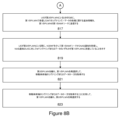
発明概念の他の実施形態によれば、方法は、複数のユニバーサル加入者識別モジュール(USIM)を有するユーザ装置(UE)内のプロセッサによって実行される。方法は、前記UEを第1の公衆陸上移動網(PLMN)に登録することを含む。方法は、前記第1のPLMNにおける第1のセッション管理機能(SMF)ノードとのプロトコルデータユニット(PDU)セッションを確立することを更に含む。方法は、前記第1のPLMNにおいて接続管理(CM)-アイドルに入ること(805)、および第2のPLMNに接続すること、を更に含む。方法は、前記UEを前記第2のPLMNに登録することを更に含む。方法は、前記第2のPLMNにおける第2のSMFノードとの第2のPDUセッションをセットアップすることを更に含む。方法は、前記第1のPLMNにおける非3GPPインターワーキング機能(N3IWF)を選択するために、前記第2のPLMNにおける前記第2のPDUセッションを介してドメインネームシステム(DNS)を使用することを更に含む。方法は、前記第2のPLMNによって提供されるインターネットプロトコル(IP)接続を介して選択された前記N3IWFにアクセスすることを更に含む。方法は、前記第1のPLMNにおける第1のアクセスおよびモビリティ管理機能(AMF)ノードに非アクセス層(NAS)メッセージを送信すること(815)を更に含み、前記NASメッセージは、前記UEが前記第1のPLMNにおけるページングをリッスンしないことを示す。
According to another embodiment of the inventive concept, the method is performed by a processor in a user equipment (UE) having a plurality of universal subscriber identity modules (USIM). The method includes registering the UE with a first public land mobile network (PLMN). The method further includes establishing a protocol data unit (PDU) session with a first session management function (SMF) node at the first PLMN. The method further includes entering connection management (CM)-idle (805) at the first PLMN and connecting to a second PLMN. The method further includes registering the UE with the second PLMN. The method further includes setting up a second PDU session with a second SMF node at the second PLMN. The method further includes using a Domain Name System (DNS) via the second PDU session in the second PLMN to select a non-3GPP interworking function (N3IWF) in the first PLMN. include. The method further includes accessing the selected N3IWF via an Internet Protocol (IP) connection provided by the second PLMN. The method further includes transmitting (815) a non-access stratum (NAS) message to a first access and mobility management function (AMF) node in the first PLMN, the NAS message indicating that the UE Indicates not to listen to paging in
また、類似の動作を行うユーザ装置およびコンピュータ製品プログラムも提供される。 User equipment and computer product programs that perform similar operations are also provided.
発明概念のさらなる実施形態によれば、公衆陸上移動網(PLMN)のアクセスおよびモビリティ管理機能(AMF)ノード内のプロセッサによって実行される方法が提供される。方法は、複数のユニバーサル加入者識別モジュール(USIM)を有するユーザ装置(UE)からのインジケーションを受信することを含み、前記インジケーションは、ネットワークノードが非アクセス層(NAS)通知のために前記UEによって指定された非3GPPインターワーキング機能(N3IWF)のみを使用することを示す。方法は、前記UEとの間で確立されたプロトコルデータユニット(PDU)セッションがインジケーションに基づき3GPPアクセスにリンクされることを示す該インジケーションをセッション管理機能(SMF)ノードに送信することを更に含む。 According to a further embodiment of the inventive concept, a method is provided which is executed by a processor in an Access and Mobility Management Function (AMF) node of a Public Land Mobile Network (PLMN). The method includes receiving an indication from a user equipment (UE) having a plurality of universal subscriber identity modules (USIMs), the indication indicating that the network node Indicates to use only non-3GPP interworking functions (N3IWF) specified by the UE. The method further includes transmitting a protocol data unit (PDU) session established with the UE to a session management function (SMF) node indicating that the protocol data unit (PDU) session established with the UE is linked to 3GPP access based on the indication. include.
また、類似の動作を行うAMFノードおよびコンピュータ製品プログラムも提供される。 AMF nodes and computer product programs that perform similar operations are also provided.
発明概念のさらに他の実施形態によれば、公衆陸上移動網(PLMN)のセッション管理機能(SMF)ノード内のプロセッサによって実行される方法が提供される。方法は、複数のユニバーサル加入者識別モジュール(USIM)を有するユーザ装置(UE)とのプロトコルデータユニット(PDU)セッションは、前記UEによって指定された非3GPPインターワーキング機能(N3IWF)を介する非アクセス層(NAS)通知を使用してのみ前記UEにより到達可能であるというインジケーションを、アクセスおよびモビリティ管理機能(AMF)ノードから受信することを含む。方法は、前記UEに対するダウンリンクパケットが到着したという通知を、ユーザプレーン機能(UPF)から受信することを更に含む。方法は、前記ダウンリンクパケットをバッファするよう前記UPFに指示することを更に含む。方法は、前記UEに対する前記ダウンリンクパケットが到着したというインジケーションを前記AMFノードに送信することを更に含む。 According to yet another embodiment of the inventive concept, a method is provided that is executed by a processor in a session management function (SMF) node of a public land mobile network (PLMN). The method provides a method for establishing a protocol data unit (PDU) session with a user equipment (UE) having multiple universal subscriber identity modules (USIMs) via a non-3GPP interworking function (N3IWF) specified by said UE. receiving an indication from an Access and Mobility Management Function (AMF) node that the UE is reachable only using a (NAS) notification. The method further includes receiving a notification from a user plane function (UPF) that a downlink packet has arrived for the UE. The method further includes instructing the UPF to buffer the downlink packets. The method further includes sending an indication to the AMF node that the downlink packet for the UE has arrived.
また、類似の動作を行うSMFノードおよびコンピュータ製品プログラムも提供される。 Also provided are SMF nodes and computer product programs that perform similar operations.
本開示のさらなる理解を提供するために含まれ、本願に組み込まれ、本願の一部を構成する添付図面は、発明概念の特定の非限定的な実施形態を示すものである。図面において: The accompanying drawings, which are included to provide a further understanding of the present disclosure and are incorporated in and constitute a part of this application, depict certain non-limiting embodiments of the inventive concepts. In the drawing:
以下、発明概念を、発明概念の実施形態の例を示す添付図面を参照しながら、より完全に説明する。しかしながら、発明概念は、多くの異なる形態で具現化され得、本明細書に記載される実施形態に限定されると解釈されるべきではない。むしろ、これらの実施形態は、本開示が徹底的かつ完全であり、当業者に本発明の発明概念の範囲を十分に伝えるように提供されるものである。また、これらの実施形態は相互に排他的でないことに留意されたい。ある実施形態からの構成要素は、別の実施形態において存在/使用されることが暗黙のうちに想定され得る。 The inventive concept will now be described more fully with reference to the accompanying drawings, which illustrate example embodiments of the inventive concept. However, the inventive concept may be embodied in many different forms and should not be construed as limited to the embodiments set forth herein. Rather, these embodiments are provided so that this disclosure will be thorough and complete, and will fully convey the scope of the inventive concepts to those skilled in the art. Also note that these embodiments are not mutually exclusive. Components from one embodiment may be implicitly assumed to be present/used in another embodiment.
以下の説明では、開示された主題の様々な実施形態を提示する。これらの実施形態は、教示例として提示されており、開示された主題の範囲を限定するものとして解釈されるべきではない。例えば、説明された実施形態の特定の詳細は、説明された主題の範囲から逸脱することなく、修正、省略、または拡張されることができる。 The following description presents various embodiments of the disclosed subject matter. These embodiments are presented as teaching examples and should not be construed as limiting the scope of the disclosed subject matter. For example, certain details of the described embodiments may be modified, omitted, or expanded upon without departing from the scope of the described subject matter.
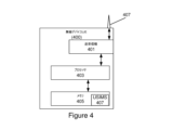
図4は、発明概念の実施形態に従って無線通信を提供するように構成された無線デバイスUE400(移動端末、移動通信端末、無線通信装置、無線端末、ユーザ装置、UE、ユーザ装置ノード/端末/デバイスなどとも呼ばれる)の要素を例示するブロック図である。(無線デバイス400は、例えば、図11の無線デバイス4110に関して後述するように、提供されてもよい。)示されるように、無線デバイスUEは、アンテナ407(たとえば、図1のアンテナ4111に対応する)と、無線アクセスネットワークの基地局(複数可)(たとえば、図1のネットワークノード4160に対応する)とのアップリンクおよびダウンリンク無線通信を提供するように構成された送信機および受信機を含む送受信機回路401(送受信機とも呼ばれ、たとえば、図1のインタフェース4114に対応)と、を含んでもよい。無線デバイスUEは、送受信機回路に結合された処理回路403(プロセッサとも呼ばれ、例えば、図1の処理回路4120に対応する)、および処理回路に結合されたメモリ回路405(メモリとも呼ばれ、例えば、図1のデバイス可読媒体4130に対応する)を含む場合もある。メモリ回路405は、処理回路403によって実行されると、処理回路に本明細書に開示される実施形態に従った動作を実行させるコンピュータ可読プログラムコードを含んでもよい。他の実施形態によれば、処理回路403は、別個のメモリ回路が必要とされないように、メモリを含むように定義されてもよい。無線デバイスUEはまた、処理回路403と結合されたインタフェース(ユーザインタフェースなど)を含んでもよく、および/または無線デバイスUEは、車両に組み込まれてもよい。無線デバイスUEはまた、複数のUSIM407を含んでもよい。
FIG. 4 shows a wireless device UE 400 (mobile terminal, mobile communication terminal, wireless communication apparatus, wireless terminal, user equipment, UE, user equipment node/terminal/device) configured to provide wireless communication according to an embodiment of the inventive concept. FIG. 2 is a block diagram illustrating elements of the system. (
本明細書で議論されるように、無線デバイスUEの動作は、処理回路403および/または送受信機回路401によって実行され得る。たとえば、処理回路403は、無線アクセスネットワークノード(基地局とも呼ばれる)に対して無線インタフェースを介して送受信機回路401を介して通信を送信するように、および/または無線インタフェースを介してRANノードから送受信機回路401を介して通信を受信するように送受信機回路401を制御してもよい。さらに、モジュールはメモリ回路405に格納されてもよく、これらのモジュールは、モジュールの命令が処理回路403によって実行されると、処理回路403がそれぞれの動作(例えば、無線デバイスに関する例示的実施形態に関して後述する動作)を実行するように命令を提供し得る。
As discussed herein, operations of wireless device UE may be performed by processing circuitry 403 and/or
図5は、発明概念の実施形態による通信を提供するように構成されたアクセスおよびモビリティ管理機能(AMF)ノード500の要素を示すブロック図である。(AMFノード500は、例えば、図1のネットワークノード4160に関して後述するように、提供されてもよい。)示されるように、ネットワークノードは、移動端末とのアップリンクおよびダウンリンク無線通信を提供するように構成された送信機および受信機を含む送受信機回路501(送受信機とも呼ばれ、例えば、図1のインタフェース4190の一部に対応する)を含んでもよい。ネットワークノードは、他のノードとの(例えば、他のネットワークノードとの)通信を提供するように構成されたネットワークインタフェース回路507(ネットワークインタフェースとも呼ばれ、例えば、図1のインタフェース4190の一部に対応する)を含んでもよい。AMFノードは、送受信機回路に結合された処理回路503(プロセッサとも呼ばれ、例えば、処理回路4170に対応する)と、処理回路に結合されたメモリ回路505(メモリとも呼ばれ、例えば、図1のデバイス可読媒体4180に対応する)とを含むこともできる。メモリ回路505は、処理回路503によって実行されると、処理回路に本明細書に開示される実施形態に従った動作を実行させるコンピュータ可読プログラムコードを含んでもよい。他の実施形態によれば、処理回路503は、別個のメモリ回路が必要とされないように、メモリを含むように定義されてもよい。
FIG. 5 is a block diagram illustrating elements of an access and mobility management function (AMF) node 500 configured to provide communications in accordance with an embodiment of the inventive concepts. (AMF node 500 may be provided, for example, as described below with respect to network node 4160 in FIG. 1.) As shown, the network node provides uplink and downlink wireless communications with mobile terminals. A transceiver circuit 501 (also referred to as a transceiver, eg, corresponding to a portion of
本明細書で論じるように、AMFノードの動作は、処理回路503、ネットワークインタフェース507、および/または送受信機501によって実行されてもよい。例えば、処理回路503は、送受信機501を制御して、無線インタフェースを介して送受信機501を通じてダウンリンク通信を1つまたは複数の移動端末UEに送信し、および/または無線インタフェースを介して1つまたは複数の移動端末UEから送受信機501を通じてアップリンク通信を受信することができる。同様に、処理回路503は、ネットワークインタフェース407を制御して、ネットワークインタフェース507を介して通信を1つ以上の他のネットワークノードに送信し、及び/又は1つ以上の他のネットワークノードからネットワークインタフェースを介して通信を受信してもよい。さらに、モジュールがメモリ505に格納されてもよく、これらのモジュールは、モジュールの命令が処理回路503によって実行されると、処理回路503がそれぞれの動作(例えば、AMFノードに関連する例示的実施形態に関して後述する動作)を実行するように命令を提供し得る。
As discussed herein, operations of an AMF node may be performed by processing circuitry 503,
いくつかの他の実施形態によれば、AMFノードは、送受信機を有さないコアネットワーク(CN)ノードとして実施されてもよい。そのような実施形態では、無線デバイスUEへの送信は、無線デバイスへの送信が送受信機を含むネットワークノードを通じて(例えば、基地局またはRANノードを通じて)提供されるように、AMFノードによって開始されてもよい。ネットワークノードが送受信機を含むネットワークノードである実施形態によれば、送信を開始することは、送受信機を通じて送信することを含んでもよい。 According to some other embodiments, an AMF node may be implemented as a core network (CN) node without a transceiver. In such embodiments, transmissions to the wireless device UE are initiated by an AMF node such that transmissions to the wireless device are provided through a network node that includes a transceiver (e.g., through a base station or a RAN node). Good too. According to embodiments where the network node is a network node that includes a transceiver, initiating the transmission may include transmitting through the transceiver.
図6は、発明概念の実施形態による通信を提供するように構成されたセッション管理機能(SMF)ノード600の要素を示すブロック図である。(SMFノード600は、例えば、図1のネットワークノード4160に関して後述するように、提供されてもよい)。示されるように、SMFノードは、移動端末とのアップリンクおよびダウンリンク無線通信を提供するように構成された送信機および受信機を含む送受信機回路601(送受信機とも呼ばれ、例えば、図1のインタフェース4190の一部に対応する)を含んでもよい。SMFノードは、他のノードとの(例えば、他のネットワークノードとの)通信を提供するように構成されたネットワークインタフェース回路607(ネットワークインタフェースとも呼ばれ、例えば、図1のインタフェース4190の一部に対応する)を含んでもよい。SMFノードは、送受信機回路に結合された処理回路603(プロセッサとも呼ばれ、例えば、図1の処理回路4170に対応する)、および処理回路に結合されたメモリ回路605(メモリとも呼ばれ、例えば、図1のデバイス可読媒体4180に対応する)を含むことができる。メモリ回路605は、処理回路603によって実行されると、処理回路に本明細書に開示される実施形態に従った動作を実行させるコンピュータ可読プログラムコードを含んでもよい。他の実施形態によれば、処理回路603は、別個のメモリ回路が必要とされないように、メモリを含むように定義されてもよい。
FIG. 6 is a block diagram illustrating elements of a session management function (SMF) node 600 configured to provide communications in accordance with an embodiment of the inventive concepts. (SMF node 600 may be provided, for example, as described below with respect to network node 4160 in FIG. 1). As shown, the SMF node includes transceiver circuitry 601 (also referred to as a transceiver, e.g., FIG. interface 4190). The SMF node includes network interface circuitry 607 (also referred to as a network interface, e.g., part of
本明細書で論じるように、SMFノードの動作は、処理回路603、ネットワークインタフェース607、および/または送受信機601によって実行され得る。例えば、処理回路603は、送受信機601を制御して、無線インタフェースを介して送受信機601を通じてダウンリンク通信を1つまたは複数のモバイル端末UEに送信し、および/または無線インタフェースを介して1つまたは複数のモバイル端末UEから送受信機601を通じてアップリンク通信を受信してもよい。同様に、処理回路603は、ネットワークインタフェース607を制御して、ネットワークインタフェース607を通じて通信を1つ以上の他のネットワークノードに送信し、及び/又は1つ以上の他のネットワークノードからネットワークインタフェースを通じて通信を受信してもよい。さらに、モジュールがメモリ605に格納されてもよく、これらのモジュールは、モジュールの命令が処理回路603によって実行されると、処理回路603がそれぞれの動作(例えば、SMFノードに関連する例示的実施形態に関して後述する動作)を実行するように命令を提供し得る。
As discussed herein, SMF node operations may be performed by processing circuitry 603,
いくつかの他の実施形態によれば、SMFノードは、送受信機を有さないコアネットワーク(CN)ノードとして実施されてもよい。そのような実施形態では、無線デバイスUEへの送信は、無線デバイスへの送信が送受信機を含むネットワークノードを通じて(例えば、基地局またはRANノードを通じて)提供されるように、SMFノードによって開始されてもよい。SMFノードが送受信機を含むネットワークノードである実施形態によれば、送信を開始することは、送受信機を通じて送信することを含んでもよい。 According to some other embodiments, an SMF node may be implemented as a core network (CN) node without a transceiver. In such embodiments, transmissions to the wireless device UE are initiated by the SMF node such that transmissions to the wireless device are provided through a network node that includes a transceiver (e.g., through a base station or a RAN node). Good too. According to embodiments where the SMF node is a network node that includes a transceiver, initiating the transmission may include transmitting through the transceiver.
UEに複数のUSIMが搭載されている場合、UEは、USIMのセットに関連する複数のネットワークのモニタリングおよび通信に関するUEの動作を調整する手段を必要とする場合がある。提起される典型的な問題は、移動体終端(MT)セッションの到達可能性に関連するもので、[1]および[2]を参照されたい。 If a UE is equipped with multiple USIMs, the UE may require a means to coordinate the UE's operations regarding monitoring and communication of multiple networks associated with the set of USIMs. Typical issues raised are related to reachability of mobile terminated (MT) sessions, see [1] and [2].
複数のUSIMを搭載したUEは、複数のUSIMが1つのオペレータから提供されている場合、同じオペレータが所有する複数のPLMN内で動作することができる(いわゆるイントラオペレータシナリオ)。ただし、USIMは異なるオペレータに関連付けられる場合もあり(すなわちインターオペレータシナリオ)、その場合、UEはこれらの異なるオペレータが運営するネットワークで動作することができる。 A UE equipped with multiple USIMs can operate within multiple PLMNs owned by the same operator (so-called intra-operator scenario) if multiple USIMs are provided by one operator. However, USIMs may also be associated with different operators (ie, an inter-operator scenario), in which case the UE may operate in networks operated by these different operators.
一実施形態では、第1のUSIMを有する第1のネットワークで動作するUEは、本明細書に記載されるように、第1のネットワーク上のユーザプレーン接続を介してトンネルを通じて、UEの第2のUSIMに関連付けられた第2のネットワークと通信することができる。 In one embodiment, a UE operating in a first network having a first USIM tunnels the UE's second network via a user plane connection on the first network, as described herein. and a second network associated with the USIM.
一実施形態では、SGPPの5GCで規定されたネットワーク機能N3IWF(非3GPPインターワーキング機能)と同様の機能を使用し、非SGPPアクセス経由の接続性を提供する。別の実施形態では、データネットワーク(例えば、IPネットワーク)経由の接続性を提供する。 In one embodiment, functionality similar to the SGPP 5GC specified network functionality N3IWF (Non-3GPP Interworking Function) is used to provide connectivity via non-SGPP access. Another embodiment provides connectivity via a data network (eg, an IP network).
単一PLMN経由のUE登録 UE registration via single PLMN
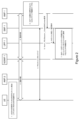
図1に示されるこの実施形態では、UEは、第2のPLMN(PLMN-2)を介して第1のPLMN(PLMN-1)に登録することができる。UEは、接続状態(例えば、CM接続)にあり、PLMN2に既に登録されていてもよい。USはPLMN2において少なくとも1つのPDUセッション設定を確立し、UEがPLMN1に登録するために使用できるIP接続を提供してもよい。 In this embodiment shown in FIG. 1, a UE may register with a first PLMN (PLMN-1) via a second PLMN (PLMN-2). The UE may be in a connected state (eg, CM connected) and already registered with the PLMN2. The US may establish at least one PDU session setup in PLMN2 and provide an IP connection that the UE can use to register with PLMN1.
UEはDNSを使用して(PLMN2のPDUセッションを介して)PLMN1のN3IWFを選択することができる。その後、UEはPLMN1内の選択されたN3IWFを介してPLMN1に対して登録手順を開始することができる。UEは選択されたN3IWFで信頼できない非3GPPアクセスの登録手順を使用する代わりに、PLMN-2の3GPPアクセスを使用してN3IWFにアクセスする。この手順が完了すると、UEはPLMN-1に登録される。 The UE may select the N3IWF of PLMN1 using DNS (via the PDU session of PLMN2). Thereafter, the UE may initiate a registration procedure to PLMN1 via the selected N3IWF in PLMN1. The UE accesses the N3IWF using the PLMN-2's 3GPP access instead of using the untrusted non-3GPP access registration procedure with the selected N3IWF. Once this procedure is completed, the UE is registered with PLMN-1.
UEはPLMN2のPDUセッションを介して、PLMN1のUEとSMF1との間にPDUセッションを確立する。UEはN3IWF上の接続のためにAMF1内でCM接続状態を維持することができるが、AMF1はこのNASシグナリング接続を通知に使用するようマークする必要がある。UEはAMF1に対して、このPDUセッションを「非アクティブ化」(すなわち、RANユーザプレーンセットアップを伴わないNASPDUセッションの確立のみ)し、3GPPアクセスにリンクさせることをインジケートする。AMFは、この情報をSMFにインジケートする。UEがCM接続状態であっても、SMF1はUPF-1に対して、ダウンリンクパケットをバッファし、ダウンリンクパケットが到着したらSMF1に通知するように指示する。 The UE establishes a PDU session between the UE of PLMN1 and SMF1 via the PDU session of PLMN2. The UE can maintain a CM connected state in AMF1 for the connection on N3IWF, but AMF1 needs to mark this NAS signaling connection to be used for notifications. The UE indicates to AMF1 to "deactivate" this PDU session (ie only establish a NASPDU session without RAN user plane setup) and link it to the 3GPP access. AMF indicates this information to SMF. Even if the UE is in the CM connected state, SMF1 instructs UPF-1 to buffer downlink packets and notify SMF1 when downlink packets arrive.
MT通信が必要な場合、AMF-1はUEにNAS通知を送信する:AMF-1→UPF-2(トンネル化NASメッセージ,UPF-2に透過)。MT通信がダウンリンクのユーザプレーンパケットによるものであった場合、そのパケットはUPF1にバッファされ、SMF1に通知される。MT通信が着信シグナリング(SMSなど)によるものである場合、AMF1は着信シグナリングについてUEに通知するが、このアクセスを通じて当該シグナリングを配信することはない。
If MT communication is required, AMF-1 sends a NAS notification to the UE: AMF-1→UPF-2 (tunneled NAS message, transparent to UPF-2). If the MT communication is based on a downlink user plane packet, the packet is buffered in the
図2に目を向けると、単一のPLMNを介したUE登録のためのシグナリングの信号フローチャートが図示されている。信号フローチャートでは、UEはPLMN2に接続および登録され、PLMN2において少なくとも1つのPDUセッションがセットアップされている。様々な構成要素が実行し得るステップは以下の通りである:
1.UEは、(PLMN2のPDUセッションによって提供されるIP接続を介して)DNSを使用してN3IWF-1を選択する。
2-3.UEは、N3IWF-1を介してPLMN1に対して登録手順を実行する。これは、TS23.502に記載されている「信頼されない非3GPPアクセスのための登録手順」に基づいている可能性がある。NASメッセージは、N3IWF-1にトンネリングされ、AMF-1に送信される。
・UEは、登録後、AMF-1がNAS通知にN3IWFのみを使用するかどうかをインジケートする。
4.UEは、SMF-1との間でPDUセッションを確立する。NASPDUセッション確立要求/受諾メッセージは、NASメッセージUL/DLのNASトランスポートで搬送され、N3IWF-1を介して送信される。NASPDUセッションのみが確立され、ユーザプレーンは確立されない。
・UEは、ユーザプレーンリソースがPDUセッションに必要ないことをSMF-1にインジケートし、PDUセッションが3GPPアクセスにリンクされることをインジケートする。
5.AMF-1は、Nsmf_PDUSession_CreateSMContext要求でSMF-1に通知する。
・AMFは、ステップ4で受け取った情報に基づいて、PDUセッションが3GPPアクセスにリンクされることをインジケートする。
6-7.SMF-1は、UPF N4セッション確立/変更要求を構成して、ダウンリンクパケットが到着すると関連するPDUセッションのダウンリンクパケットをバッファしSMF-1に通知するように設定する。SMF-1は、AMF-1に通知し、AMF-1は、N3IWFを通して(PLMN1のページングの代わりに)UEにNAS通知を配信する。
Turning to FIG. 2, a signal flowchart of signaling for UE registration over a single PLMN is illustrated. In the signaling flowchart, the UE has connected and registered with PLMN2, and at least one PDU session has been set up in PLMN2. The steps that various components may perform are as follows:
1. The UE selects N3IWF-1 using DNS (via the IP connectivity provided by PLMN2's PDU session).
2-3. The UE performs a registration procedure to PLMN1 via N3IWF-1. This may be based on the "Registration Procedure for Untrusted Non-3GPP Access" described in TS 23.502. The NAS message is tunneled to N3IWF-1 and sent to AMF-1.
- After registration, the UE indicates whether AMF-1 uses only N3IWF for NAS notifications.
4. The UE establishes a PDU session with SMF-1. The NASPDU session establishment request/accept message is carried on the NAS transport of the NAS message UL/DL and is sent via the N3IWF-1. Only a NASPDU session is established, no user plane.
- The UE indicates to SMF-1 that user plane resources are not required for the PDU session and indicates that the PDU session is linked to 3GPP access.
5. AMF-1 notifies SMF-1 with a Nsmf_PDUSession_CreateSMContext request.
- The AMF indicates that the PDU session is linked to 3GPP access based on the information received in step 4.
6-7. SMF-1 configures the UPF N4 Session Establishment/Modification Request to buffer the downlink packets of the associated PDU session and notify SMF-1 when the downlink packets arrive. SMF-1 notifies AMF-1 and AMF-1 delivers the NAS notification to the UE through N3IWF (instead of PLMN1 paging).
UEは、3GPPアクセスを使ってPLMN-1とPLMN-2に別々に登録する。 The UE registers separately with PLMN-1 and PLMN-2 using 3GPP access.
本実施形態において、各構成要素が実行しうるステップは以下の通りである:
1.UEは、AMF-1/PLMN-1に登録し、SMF-1/PLMN-1の3GPPアクセスを介してPDUセッションをアクティブ化する。
2.UEは、CMアイドルに入り、PLMN-2を再選択する。
3.UEは、AMF-2/PLMN-2に登録し、IP接続を提供するSMF-2/PLMN-2のPDUセッションをアクティブ化する。
4.UEは、PLMN-2のPDUセッションを使用して、ユーザプレーンを介してDNSを使用してN3-IWF-1を選択する。
5.UEは、N3IWF-1を介して到達可能になったことをAMF-1にシグナリングする。
UEは、AMF-1に対して、登録後、AMF-1はPLMN1のRANを通じてページングする代わりにN3IWFを通じてUEへの通知を試行することをインジケートする必要がある場合がある。
6.AMF-1は、Nsmf_PDUSession_CreateSMContext要求をSMF-1に通知する。
AMFは、受信した情報に基づき、PDUセッションは3GPPアクセスにリンクされることをインジケートする。
7.PLMN-1でMT通信の必要性がある場合、AMF-1は、N3IWF-1を介してUEに通知メッセージを送信する。
In this embodiment, the steps that each component can perform are as follows:
1. The UE registers with AMF-1/PLMN-1 and activates a PDU session via 3GPP access of SMF-1/PLMN-1.
2. The UE enters CM Idle and reselects PLMN-2.
3. The UE registers with AMF-2/PLMN-2 and activates a PDU session of SMF-2/PLMN-2 providing IP connectivity.
4. The UE uses PLMN-2's PDU session to select N3-IWF-1 using DNS over the user plane.
5. The UE signals AMF-1 that it is now reachable via N3IWF-1.
The UE may need to indicate to AMF-1 that after registration, AMF-1 will attempt to notify the UE through N3IWF instead of paging through PLMN1's RAN.
6. AMF-1 notifies SMF-1 of the Nsmf_PDUSession_CreateSMContext request.
Based on the received information, the AMF indicates that the PDU session is linked to 3GPP access.
7. If there is a need for MT communication in PLMN-1, AMF-1 sends a notification message to the UE via N3IWF-1.
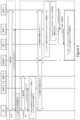
図3に、3GPPアクセスを使用してPLMN-1とPLMN-2に別々に登録するUEの信号フローチャートを示す。この信号フローチャートでは、UEはPLMN1に接続されている。様々な構成要素が実行し得るステップは以下の通りである:
1.UEは、PLMN1に対して登録手順を実行する。
2.UEは、SMF-1とのPDUセッションをセットアップする。
3.UEは、CMアイドルに入り、PLMN2を再選択する。
4.PLMN2に接続されると、UEは、PLMN2に対して登録手順を実行する。
5.UEは、SMF-2とPDUセッションをセットアップする。
6.UEは、(PLMN-2のPDUセッションによって提供されるIP接続を介して)DNSを使用してN3IWF-1を選択する。
7.UEは、AMF-1に対して、PLMN1ネットワークでページングをリッスンしないことを通知する。これは、NASメッセージ(例えば、特定のインジケーションを有する登録要求)を送信することで達成される。
注:同じ結果を得るために、新しいNASメッセージを定義することも可能である。
8.ステップ7でのインジケーションに基づき、AMF-1は、NAS通知メッセージによってUEに到達するNASメッセージを受信したN3IWF-1を介して、さらなるMTのデータ/シグナリング通信のためにNASシグナリング接続をマークする。
9-10.AMF-1は、Nsmf_PDUSession_CreateSMContext要求でSMF-1に通知する。
a.AMFは、SMF-1PDUセッションが「非アクティブ」であること(すなわち、ユーザプレーンのリソースがある場合は解放されること)を通知する。
11-12.SMF-1は、ダウンリンクパケットが到着したとき、関連するPDUセッションのダウンリンクパケットをバッファしSMF-1に通知するようにUPFを構成する。SMF-1は、AMF-1に通知し、AMF-1は、N3IWFを通して(PLMN1でのページングの代わりに)UEにNAS通知を配信する。
FIG. 3 shows a signaling flowchart of a UE registering separately to PLMN-1 and PLMN-2 using 3GPP access. In this signal flowchart, the UE is connected to PLMN1. The steps that various components may perform are as follows:
1. The UE performs a registration procedure to PLMN1.
2. The UE sets up a PDU session with SMF-1.
3. The UE enters CM idle and reselects PLMN2.
4. Once connected to PLMN2, the UE performs a registration procedure to PLMN2.
5. The UE sets up a PDU session with SMF-2.
6. The UE selects N3IWF-1 using DNS (via the IP connectivity provided by PLMN-2's PDU session).
7. The UE informs AMF-1 that it will not listen to paging on the PLMN1 network. This is accomplished by sending a NAS message (eg, a registration request with specific indications).
Note: It is also possible to define new NAS messages to achieve the same result.
8. Based on the indication in step 7, the AMF-1 marks the NAS signaling connection for further MT data/signaling communication via the N3IWF-1 that received the NAS message reaching the UE via the NAS notification message. .
9-10. AMF-1 notifies SMF-1 with a Nsmf_PDUSession_CreateSMContext request.
a. The AMF signals that the SMF-1 PDU session is "inactive" (ie, user plane resources, if any, are to be released).
11-12. SMF-1 configures the UPF to buffer and notify SMF-1 of the downlink packets of the associated PDU session when the downlink packets arrive. SMF-1 notifies AMF-1, which delivers the NAS notification to the UE through N3IWF (instead of paging at PLMN1).
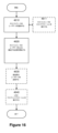
ユーザ装置400の動作(図4のブロック図の構造を使用して実施される)は、次に、発明概念のいくつかの実施形態による図7のフローチャートを参照して説明される。たとえば、モジュールは、図4のメモリ405に格納されてもよく、これらのモジュールは、モジュールの命令がそれぞれの無線機器の処理回路403によって実行されると、処理回路403がフローチャートのそれぞれの動作を実行するように、命令を提供し得る。 The operation of user equipment 400 (implemented using the block diagram structure of FIG. 4) will now be described with reference to the flowchart of FIG. 7 according to some embodiments of the inventive concept. For example, the modules may be stored in memory 405 of FIG. 4 such that when the instructions of the modules are executed by the processing circuitry 403 of the respective wireless device, the processing circuitry 403 performs the respective operations of the flowchart. Instructions may be provided for execution.
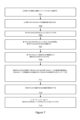
次に図7に目を向けると、ブロック701において、処理回路403は、UEを第1の公衆陸上移動網(PLMN)に登録する。ブロック703において、処理回路403は、UEを接続管理(CM)-接続状態に移行させる。
Turning now to FIG. 7, at
ブロック705において、処理回路403は、第1のPLMNにおいてプロトコルデータユニット(PDU)セッションをセットアップする。ブロック707において、処理回路403は、第1のPLMNにおけるPDUセッションを介して、ドメインネームシステム(DNS)を使用して、第2のPLMNにおける非3GPPインターワーキング機能(N3IWF)を選択する。
At block 705, processing circuitry 403 sets up a protocol data unit (PDU) session at the first PLMN. At
ブロック709において、処理回路403は、第1のPLMNによって提供されるIP(インターネットプロトコル)接続を介して、選択されたN3IWFにアクセスする。ブロック711において、処理回路403は、選択されたN3IWFを使用して第2のPLMNの第1のアクセスおよびモビリティ管理機能(AMF)ノードとの登録手順を開始し、UEは、AMFノードが登録後に非アクセス層(NAS)通知の対してのみN3IFWを使用することをインジケートする。
At
ブロック713において、処理回路403は、第2のPLMNに登録するための登録手順を完了する。ブロック715において、処理回路403は、ユーザプレーンリソースなしで第2のPLMNのセッション管理機能(SMF)ノードとPDUセッションをセットアップする。
At
第2のPLMNのSMFノードとのPDUセッションをセットアップする際に、処理回路403は、ユーザプレーンリソースがPDUセッションに必要ないことをSMFノードにインジケートしてもよい。第2のPLMNのSMFノードとのPDUセッションのセットアップにおいて、処理回路403は、さらに、PDUセッションが3GPPアクセスを使用して選択されたN3WIFを介してリンクされることをインジケートしてもよい。 Upon setting up a PDU session with the SMF node of the second PLMN, the processing circuit 403 may indicate to the SMF node that user plane resources are not required for the PDU session. In setting up the PDU session with the SMF node of the second PLMN, the processing circuit 403 may further indicate that the PDU session is linked via the selected N3WIF using 3GPP access.
別の実施形態では、ユーザ装置400の動作(図4のブロック図の構造を使用して実施される)が、次に、発明概念のいくつかの実施形態による図8のフローチャートを参照して説明される。たとえば、モジュールは、図4のメモリ405に格納されてもよく、これらのモジュールは、モジュールの命令がそれぞれの無線機器の処理回路403によって実行されると、処理回路403がフローチャートのそれぞれの動作を実行するように、命令を提供してもよい。 In another embodiment, the operation of user equipment 400 (implemented using the structure of the block diagram of FIG. 4) is now described with reference to the flowchart of FIG. 8 according to some embodiments of the inventive concept. be done. For example, the modules may be stored in memory 405 of FIG. 4 such that when the instructions of the modules are executed by the processing circuitry 403 of the respective wireless device, the processing circuitry 403 performs the respective operations of the flowchart. Instructions may be provided for execution.
次に図8に目を向けると、ブロック801において、処理回路403は、UEを第1の公衆陸上移動網(PLMN)に登録する。ブロック803において、処理回路403は、第1のPLMNにおける第1のセッション管理機能(SMF)ノードとの間でプロトコルデータユニット(PDU)セッションを確立する。
Turning now to FIG. 8, at block 801, processing circuitry 403 registers a UE with a first public land mobile network (PLMN). At
ブロック805において、処理回路403は、第1のPLMNにおける接続管理(CM)アイドルに入り、第2のPLMNに接続する。ブロック807において、処理回路403は、UEを第2のPLMNに登録する。
At
ブロック809において、処理回路403は、第2のPLMN内の第2のSMFノードとの第2のPDUセッションをセットアップする。ブロック811において、処理回路403は、第2のPLMNにおける第2のPDUセッションを介して、ドメインネームシステム(DNS)を使用して、第1のPLMNにおける非3GPPインターワーキング機能(N3IWF)を選択する。
At
ブロック813において、処理回路403は、第2のPLMNによって提供されるインターネットプロトコル(IP)接続を介して、選択されたN3IWFにアクセスする。ブロック815において、処理回路403は、送受信機401を介して、非アクセス層(NAS)メッセージを第1のPLMNの第1のアクセスおよびモビリティ管理機能(AMF)ノードに送信し、NASメッセージは、UEが第1のPLMNにおいてページングをリッスンしないことをインジケートする。
At
ブロック817において、処理回路403は、第1のPLMNの第1のAMFノードに、UEが第2のPLMNにいるときのために第1のPLMNで受信した移動体終端(MT)のシグナリング/データの処理に関する追加情報を送信してもよい。追加情報を送信する際に、処理回路は、UEが第2のPLMNにいる間に、UEによって選択されたサービスクラスのMTのシグナリングまたはデータが第1のPLMNで受信されたときに通知されるように、UEが選択したサービスクラスを示す情報を送信してもよい。別の実施形態では、処理回路は、UEが第2のPLMNにいる間に、UEは第2のPLMNにいる間はページングされないという情報と、UEによって選択されたサービスクラスのMTのシグナリングまたはデータが第1のPLMNで受信されたときに、UEによって選択されたサービスクラスに対してUEに通知が送信されるという情報と、を送信することができる。
At
ブロック819において、処理回路403は、UEが第2のPLMNにいる間に、N3IWFを介して、第1のPLMNの第1のAMFノードからNAS通知を受信し、NAS通知は、UEに対して移動体終端のシグナリングまたはデータのいずれかが第1のPLMNに到着していることをインジケートする。一実施形態では、NAS通知は、ブロック817において上述した実施形態のうちの1つにおいてUEによって選択されたサービスクラスに対してのみ受信され得る。
At
ブロック821において、処理回路403は、第2のPLMNを離れ、第1のPLMNを再選択して移動体終端のシグナリングまたはデータの一方を取得する。ブロック823において、処理回路403は、移動体終端のシグナリングまたはデータの一方を取得することに応答して、第1のPLMNを離れ、第2のPLMNを再選択する。
At
図8のフローチャートからの様々な動作は、無線デバイスおよび関連する方法のいくつかの実施形態に関して、任意であってよい。例示的な実施形態4の方法(以下に記載する)に関して、たとえば、図8のブロック817、819、821、および823の動作はオプションであり得る。
Various operations from the flowchart of FIG. 8 may be optional with respect to some embodiments of wireless devices and related methods. With respect to the method of example embodiment 4 (described below), for example, the operations of
アクセスおよびモビリティ管理機能(AMF)ノード500の動作(図5の構造を使用して実施される)が、次に、発明概念のいくつかの実施形態による図9のフローチャートを参照して説明される。例えば、モジュールは、図5のメモリ505に格納されてもよく、これらのモジュールは、モジュールの命令がそれぞれのネットワークノード処理回路503によって実行されると、処理回路503がフローチャートのそれぞれの動作を実行するように命令を提供することができる。 The operation of the access and mobility management function (AMF) node 500 (implemented using the structure of FIG. 5) will now be described with reference to the flowchart of FIG. 9 according to some embodiments of the inventive concept. . For example, modules may be stored in memory 505 of FIG. 5 such that when the module's instructions are executed by the respective network node processing circuitry 503, the processing circuitry 503 performs the respective operations in the flowchart. We can provide you with instructions to do so.
次に図9に目を向けると、ブロック901において、処理回路503は、複数のユニバーサル加入者識別モジュール(USIM)を有するユーザ装置(UE)からインジケーションを受信し、インジケーションは、ネットワークノードが非アクセス層(NAS)通知に対してUEによって指定された非3GPPインターワーキング機能(N3IWF)のみを使用することをインジケートする。
Turning now to FIG. 9, at
ブロック903において、処理回路503は、送受信機回路501および/またはネットワークインタフェース回路507を介して、UEとの間で確立されたプロトコルデータユニット(PDU)セッションが、インジケーションに基づいて3GPPアクセスにリンクされるというインジケーションをセッション管理機能(SMF)ノードに送信する。
At
ブロック905において、処理回路503は、送受信機回路501および/またはネットワークインタフェース回路507を介して、UEが第2のPLMNにいる間に第1のPLMNでMTのシグナリング/データを処理することに関する情報を有する要求をUEから受信する。情報を有する要求を受信することは、UEが第2のPLMNにいる間に、通知されるためにどのサービスクラスおよび時間期間をUEが選択したかを示す情報を有する要求を受信することを含む。別の実施形態では、情報を有する要求を受信することは、UEが第2のPLMNにいる間に、UEによってインジケートされた時間期間に第2のPLMNにいる間は、UEはページングされないという情報と、UEによって選択されたサービスクラスに対してMTのシグナリングまたはデータが第1のPLMNで受信されたときにUEによって選択されたサービスクラスに対してUEにNAS通知が送信されるという情報と、を有する要求を受信することを含む。
At
ブロック907において、処理回路503は、送受信機回路501および/またはネットワークインタフェース回路507を介して、SMFノードから、UEに対するダウンリンクパケットが到着したという通知を受信してもよい。ブロック909において、処理回路503は、ダウンリンクパケットがUEによって選択されたサービスクラスの1つに対するものであるか否かを決定する。例えば、処理回路903は、ダウンリンクパケットのサービスクラスをUEによって選択されたサービスクラスと比較して、ダウンリンクパケットのサービスクラスがUEによって選択されたサービスクラスのいずれかと一致するかどうかを決定してもよい。
At
ブロック911において、処理回路503は、ダウンリンクパケットがUEによって選択されたサービスクラスの1つに対するものであると決定することに応答して、送受信機回路501および/またはネットワークインタフェース回路505を介して、N3IWFを介して、ダウンリンクパケットが到着したというNAS通知をUEに送信する。
At
ブロック905の情報がいかなるサービスクラスも指定しない一実施形態では、処理回路503は、通知の受信に応答して、ブロック911において、UEによって指定されたN3IWFを介して、ダウンリンクパケットが到着したというNAS通知をUEに送信してよい。言い換えれば、NAS通知は、受信された任意のダウンリンクパケットについてUEに送信される。
In one embodiment where the information in
ブロック913において、処理回路503は、ダウンリンクパケットがUEによって選択されたサービスクラスの1つに対するものではないと決定することに応答して、ダウンリンクパケットがドロップされ得ることをSMFノードに通知する。
At
図9のフローチャートからの様々な動作は、ネットワークノードおよび関連する方法のいくつかの実施形態に関してオプションであり得る。例示的な実施形態15(以下に記載)の方法に関して、例えば、図9のブロック905、907、909、911、および913の動作はオプションであり得る。
Various operations from the flowchart of FIG. 9 may be optional with respect to some embodiments of network nodes and related methods. With respect to the method of example embodiment 15 (described below), for example, the acts of
セッション管理機能(SMF)ノード600の動作(図6の構造を使用して実施される)は、次に、発明概念のいくつかの実施形態に従って、図10のフローチャートを参照して説明される。例えば、モジュールは、図6のメモリ605に格納されてもよく、これらのモジュールは、モジュールの命令がそれぞれのネットワークノード処理回路603によって実行されると、処理回路603がフローチャートのそれぞれの動作を実行するように命令を提供することができる。
The operation of session management function (SMF) node 600 (implemented using the structure of FIG. 6) will now be described with reference to the flowchart of FIG. 10, in accordance with some embodiments of the inventive concept. For example, modules may be stored in
次に図10に目を向けると、ブロック1001において、処理回路603は、送受信機回路601および/またはネットワークインタフェース回路607を介して、複数のユニバーサル加入者識別モジュール(USIM)を有するユーザ装置(UE)とのプロトコルデータユニット(PDU)セッションは、非アクセス層(NAS)通知を用いてUEによって指定される非3GPPインターワーキング機能(N3IWF)を介してのみ到達可能であるというインジケーションを、アクセスおよびモビリティ管理機能(AMF)ノードから受信する。
Turning now to FIG. 10, at
ブロック1003において、処理回路603は、送受信機回路601および/またはネットワークインタフェース回路607を介して、ユーザプレーン機能(UPF)から、UE用のダウンリンクパケットが到着したことの通知を受信する。
At
ブロック1005において、処理回路603は、ダウンリンクパケットをバッファするようにUPFに指示する。ブロック1007において、処理回路603は、送受信機回路601および/またはネットワークインタフェース回路607を介して、UEに対するダウンリンクパケットが到着したというインジケーションをAMFノードに送信する。
At
ブロック1009において、処理回路603は、AMFに指示を送信することに応答して、AMFから、ダウンリンクパケットをドロップすることができる旨の通知を受信してもよい。ブロック1011において、処理回路603は、送受信機回路601および/またはネットワークインタフェース回路607を介して、UPFに、通知を受信することに応答してダウンリンクパケットをドロップするように指示してもよい。
At
図10のフローチャートからの様々な動作は、ネットワークノードおよび関連する方法のいくつかの実施形態に関してオプションであり得る。例示的な実施形態26(以下に示す)の方法に関して、例えば、図10のブロック1009および1011の動作はオプションであり得る。
Various operations from the flowchart of FIG. 10 may be optional with respect to some embodiments of network nodes and associated methods. With respect to the method of example embodiment 26 (described below), for example, the acts of
以下、具体的な実施形態例について説明する。
実施形態1. 複数のユニバーサル加入者識別モジュール(USIM)を有するユーザ装置(UE)内のプロセッサによって実行される方法であって、
前記UEを第1の公衆陸上移動網(PLMN)に登録すること(701)と、
前記UEを前記第1のPLMNにおける接続管理(CM)-接続状態に移行させること(703)と、
前記第1のPLMNにおけるプロトコルデータユニット(PDU)セッションをセットアップすること(705)と、
第2のPLMNにおける非3GPPインターワーキング機能(N3IWF)を選択するために、前記第1のPLMNにおける前記PDUセッションを介してドメインネームシステム(DNS)を使用すること(707)と、
前記第1のPLMNによって提供されるインターネットプロトコル(IP)接続を介して選択された前記N3IWFにアクセスすること(709)と、
選択された前記N3IWFを使用して前記第2のPLMNにおける第1のアクセスおよびモビリティ管理機能(AMF)ノードとの登録手順を開始すること(711)であって、前記UEは、登録後の非アクセス層(NAS)通知に対してのみ前記AMFノードがN3IFWを使用することを示す、前記開始すること(711)と、
前記第2のPLMNに登録するための前記登録手順を完了すること(713)と、
ユーザプレーンリソースなしで前記第2のPLMNにおけるセッション管理機能(SMF)ノードとのPDUセッションをセットアップすること(715)と、
を含む、方法。
実施形態2. 前記第2のPLMNにおける前記SMFノードとの前記PDUセッションをセットアップすることにおいて、前記UEは、ユーザプレーンリソースが前記PDUセッションに必要ないことを前記SMFノードに示す実施形態1に記載の方法。
実施形態3. 前記第2のPLMNにおける前記SMFノードとの前記PDUセッションをセットアップすることにおいて、前記UEは、3GPPアクセスを使用して選択された前記N3IWFを介して前記PDUセッションがリンクされることを更に示す実施形態1または2に記載の方法。
実施形態4. 複数のユニバーサル加入者識別モジュール(USIM)を有するユーザ装置(UE)内のプロセッサによって実行される方法であって、
前記UEを第1の公衆陸上移動網(PLMN)に登録すること(801)と、
前記第1のPLMNにおける第1のセッション管理機能(SMF)ノードとのプロトコルデータユニット(PDU)セッションを確立すること(803)と、
前記第1のPLMNにおいて接続管理(CM)-アイドルに入り(805)、第2のPLMNに接続することと、
前記UEを前記第2のPLMNに登録すること(807)と、
前記第2のPLMNにおける第2のSMFノードとの第2のPDUセッションをセットアップすること(809)と、
前記第1のPLMNにおける非3GPPインターワーキング機能(N3IWF)を選択するために、前記第2のPLMNにおける前記第2のPDUセッションを介してドメインネームシステム(DNS)を使用すること(811)と、
前記第2のPLMNによって提供されるインターネットプロトコル(IP)接続を介して選択された前記N3IWFにアクセスすること(813)と、
前記第1のPLMNにおける第1のアクセスおよびモビリティ管理機能(AMF)ノードに非アクセス層(NAS)メッセージを送信すること(815)であって、前記NASメッセージは、前記UEが前記第1のPLMNにおけるページングをリッスンしないことを示す、前記送信すること(815)と、
を含む、方法。
実施形態5. 前記UEが前記第2のPLMNにいるときのために、前記第1のPLMNにおける前記第1のAMFノードに、前記第1のPLMNにおいて受信された移動体終端(MT)のシグナリング/データの処理に関する追加情報を送信すること(817)をさらに含む実施形態4に記載の方法。
実施形態6. 前記追加情報を送信することは、前記UEが前記第2のPLMNにいる間に、前記UEによって選択されたサービスクラスのMTのシグナリングまたはデータが前記第1のPLMNで受信されたときに通知されるように前記UEが選択した前記サービスクラスを示す情報を送信することを含む実施形態5に記載の方法。
実施形態7. 前記追加情報を送信することは、前記UEが前記第2のPLMNにいる間に、前記UEは前記第2のPLMNにいる間はページングされないという情報と、前記UEによって選択されたサービスクラスのMTのシグナリングまたはデータが前記第1のPLMNで受信されたときに前記UEによって選択された前記サービスクラスに対して前記UEに通知が送信されるという情報と、を送信することを含む実施形態5に記載の方法。
実施形態8. 前記UEが前記第2のPLMNにいる間に前記第1のPLMNにおける前記第1のAMFノードからNAS通知をN3IWFを介して受信すること(819)であって、前記NAS通知は、前記UEに対して移動体終端のシグナリングまたはデータの一方が前記第1のPLMNに到着していることを示す、前記受信すること(819)をさらに含む実施形態4に記載の方法。
実施形態9. 前記移動体終端のシグナリングまたはデータの前記一方を取得するために、前記第2のPLMNを離れ(821)、前記第1のPLMNを再選択することをさらに含む実施形態8に記載の方法。
実施形態10. 前記移動体終端のシグナリングまたはデータの前記一方を取得することに応答して、前記第1のPLMNを離れ(823)、前記第2のPLMNを再選択することをさらに含む実施形態9に記載の方法。
実施形態11. 通信ネットワーク内で動作するように構成された無線デバイス(300)であって、
処理回路(303)と、
前記処理回路と結合されたメモリ(305)と、
を備え、
前記メモリは、前記処理回路によって実行されたとき、前記無線デバイスに、実施形態1-10の何れか1項に従った動作を実行させる命令を含む
無線デバイス(300)。
実施形態12. 通信ネットワーク内で動作するように構成された無線デバイス(300)であって、実施形態1-10の何れか1項に従って実行するのに適合した無線デバイス(300)。
実施形態13. 通信ネットワーク内で動作するように構成された無線デバイス(300)の処理回路(303)によって実行されるプログラムコードを含むコンピュータプログラムであって、プログラムコードの実行は、無線デバイス(300)に実施形態1-10の何れか1項による動作を実行させるコンピュータプログラム。
実施形態14. 通信ネットワーク内で動作するように構成された無線デバイス(300)の処理回路(303)によって実行されるプログラムコードを含む非一時的記憶媒体を含むコンピュータプログラム製品であって、プログラムコードの実行は、無線デバイス(300)に実施形態1-10の何れか1項による動作を実行させるプログラム製品。
実施形態15. 公衆陸上移動網(PLMN)のアクセスおよびモビリティ管理機能(AMF)ノード内のプロセッサによって実行される方法であって、
複数のユニバーサル加入者識別モジュール(USIM)を有するユーザ装置(UE)からのインジケーションを受信すること(901)であって、前記インジケーションは、ネットワークノードが非アクセス層(NAS)通知のために前記UEによって指定された非3GPPインターワーキング機能(N3IWF)のみを使用することを示す、前記受信すること(901)と、
前記UEとの間で確立されたプロトコルデータユニット(PDU)セッションがインジケーションに基づき3GPPアクセスにリンクされることを示す該インジケーションをセッション管理機能(SMF)ノードに送信すること(903)と、
を含む、方法。
実施形態16. 前記UEが前記第2のPLMNにいる間に、前記UEから、前記第1のPLMNにおけるMTのシグナリング/データの処理に関する情報を有する要求を受信すること(905)をさらに含む実施形態15に記載の方法。
実施形態17. 情報を有する前記要求を受信することは、前記UEが前記第2のPLMNにいる間に、通知されるためにどのサービスクラスおよび時間期間を前記UEが選択したかを示す前記情報を有する前記要求を受信することを含む実施形態16に記載の方法。
実施形態18. 情報を有する前記要求を受信することは、前記UEが前記第2のPLMNにいる間に、UEによってインジケートされた前記時間期間に前記第2のPLMNにいる間は、前記UEはページングされないという情報と、前記UEによって選択された前記サービスクラスに対してMTのシグナリングまたはデータが前記第1のPLMNで受信されたときに前記UEは該UEによって選択された前記サービスクラスに対して該UEに通知が送信されるという情報と、を有する前記要求を受信することを含む実施形態17に記載の方法。
実施形態19. 前記SMFノードから、前記UEに対するダウンリンクパケットが到着したという通知を受信すること(907)と、
前記通知を受信することに応答して、前記UEによって指定された前記N3IWFを介して、前記ダウンリンクパケットが到着したというNAS通知を前記UEに送信すること(911)と、
をさらに含む実施形態15-18の何れか1項に記載の方法。
実施形態20. 前記SMFノードから、前記UEに対するダウンリンクパケットが到着したという通知を受信すること(907)と、
前記ダウンリンクパケットが前記UEによって選択されたサービスクラスの1つに対するものであるか否かを決定すること(909)と、
前記ダウンリンクパケットが前記UEによって選択されたサービスクラスの1つに対するものであると決定することに応答して、前記N3IWFを介して、前記ダウンリンクパケットが到着したというNAS通知を前記UEに送信すること(911)と、
をさらに含む実施形態17-18の何れか1項に記載の方法。
実施形態21. 前記SMFノードから、前記UEに対するダウンリンクパケットが到着したという通知を受信すること(907)と、
前記ダウンリンクパケットが前記UEによって選択されたサービスクラスの1つに対するものであるか否かを決定すること(911)と、
前記ダウンリンクパケットが前記UEによって選択されたサービスクラスの1つに対するものではないと決定することに応答して、前記ダウンリンクパケットがドロップされ得ることを前記SMFノードに通知すること(913)と、
をさらに含む実施形態17-18の何れか1項に記載の方法。
実施形態22. 通信ネットワーク内で動作するように構成されたアクセスおよびモビリティ管理機能(AMF)ノード(500)であって、
処理回路(503)と、
前記処理回路と結合されたメモリ(505)と、
を備え、
前記メモリは、前記処理回路によって実行されたとき、前記AMFノードに、実施形態15-21の何れか1項に従った動作を実行させる命令を含む
AMFノード(500)。
実施形態23. 通信ネットワーク内で動作するように構成されたアクセスおよびモビリティ管理機能(AMF)ノード(500)であって、実施形態15-21の何れか1項に従って実行するのに適合したAMFノード(500)。
実施形態24. 通信ネットワーク内で動作するように構成されたアクセスおよびモビリティ管理機能(AMF)ノード(500)の処理回路(503)によって実行されるプログラムコードを含むコンピュータプログラムであって、プログラムコードの実行は、AMFノード(500)に実施形態15-21の何れか1項による動作を実行させるコンピュータプログラム。
実施形態25. 通信ネットワーク内で動作するように構成されたアクセスおよびモビリティ管理機能(AMF)ノード(500)の処理回路(503)によって実行されるプログラムコードを含む非一時的記憶媒体を含むコンピュータプログラム製品であって、プログラムコードの実行は、AMFノード(500)に実施形態15-21の何れか1項による動作を実行させるプログラム製品。
実施形態26. 公衆陸上移動網(PLMN)のセッション管理機能(SMF)ノード内のプロセッサによって実行される方法であって、
複数のユニバーサル加入者識別モジュール(USIM)を有するユーザ装置(UE)とのプロトコルデータユニット(PDU)セッションは、前記UEによって指定された非3GPPインターワーキング機能(N3IWF)を介する非アクセス層(NAS)通知を使用してのみ前記UEにより到達可能であるというインジケーションを、アクセスおよびモビリティ管理機能(AMF)ノードから受信すること(1001)と、
前記UEに対するダウンリンクパケットが到着したという通知を、ユーザプレーン機能(UPF)から受信すること(1003)と、
前記ダウンリンクパケットをバッファするよう前記UPFに指示すること(1005)と、
前記UEに対する前記ダウンリンクパケットが到着したというインジケーションを前記AMFノードに送信すること(1007)と、
を含む、方法。
実施形態27. 前記AMFに前記指示を送信することに応答して、前記ダウンリンクパケットがドロップし得るという通知を前記AMFから受信すること(1009)をさらに含む実施形態26に記載の方法。
実施形態28. 前記通知を受信することに応答して、前記ダウンリンクパケットをドロップするように前記UPFに指示すること(1011)をさらに含む実施形態27に記載の方法。
実施形態29. 通信ネットワーク内で動作するように構成されたセッション管理機能(SMF)ノード(600)であって、
処理回路(603)と、
前記処理回路と結合されたメモリ(605)と、
を備え、
前記メモリは、前記処理回路によって実行されたとき、前記SMFノードに、実施形態26-28の何れか1項に従った動作を実行させる命令を含む
SMFノード(600)。
実施形態30. 通信ネットワーク内で動作するように構成されたセッション管理機能(SMF)ノード(600)であって、実施形態26-28の何れか1項に従って実行するのに適合したSMFノード(600)。
実施形態31. 通信ネットワーク内で動作するように構成されたセッション管理機能(SMF)ノード(600)の処理回路(603)によって実行されるプログラムコードを含むコンピュータプログラムであって、プログラムコードの実行は、SMFノード(600)に実施形態26-28の何れか1項による動作を実行させるコンピュータプログラム。
実施形態32. 通信ネットワーク内で動作するように構成されたセッション管理機能(SMF)ノード(600)の処理回路(603)によって実行されるプログラムコードを含む非一時的記憶媒体を含むコンピュータプログラム製品であって、プログラムコードの実行は、SMFノード(600)に実施形態26-28の何れか1項による動作を実行させるプログラム製品。
Hereinafter, specific embodiments will be described.
registering (701) the UE with a first public land mobile network (PLMN);
transitioning the UE to a connection management (CM)-connected state in the first PLMN (703);
setting up (705) a protocol data unit (PDU) session at the first PLMN;
using a Domain Name System (DNS) via the PDU session at the first PLMN to select a non-3GPP interworking function (N3IWF) at a second PLMN (707);
accessing (709) the selected N3IWF via an Internet Protocol (IP) connection provided by the first PLMN;
initiating (711) a registration procedure with a first access and mobility management function (AMF) node in the second PLMN using the selected N3IWF, wherein the UE the initiating (711) indicating that the AMF node uses N3IFW only for access stratum (NAS) notifications;
completing (713) the registration procedure for registering with the second PLMN;
setting up (715) a PDU session with a session management function (SMF) node at the second PLMN without user plane resources;
including methods.
Embodiment 3. In setting up the PDU session with the SMF node in the second PLMN, the UE includes implementations further indicating that the PDU session is linked via the selected N3IWF using 3GPP access. The method according to
Embodiment 4. A method performed by a processor in a user equipment (UE) having multiple universal subscriber identity modules (USIM), the method comprising:
registering (801) the UE with a first public land mobile network (PLMN);
establishing (803) a protocol data unit (PDU) session with a first session management function (SMF) node at the first PLMN;
Entering connection management (CM)-idle (805) in the first PLMN and connecting to a second PLMN;
registering the UE with the second PLMN (807);
setting up (809) a second PDU session with a second SMF node in the second PLMN;
using a Domain Name System (DNS) via the second PDU session at the second PLMN to select a non-3GPP interworking function (N3IWF) at the first PLMN (811);
accessing (813) the selected N3IWF via an Internet Protocol (IP) connection provided by the second PLMN;
sending (815) a non-access stratum (NAS) message to a first access and mobility management function (AMF) node in the first PLMN, the NAS message indicating that the UE said transmitting (815) indicating not to listen for paging at;
including methods.
Embodiment 5. processing of mobile terminal (MT) signaling/data received at the first PLMN to the first AMF node in the first PLMN for when the UE is in the second PLMN; 5. The method as in embodiment 4, further comprising transmitting (817) additional information regarding.
Embodiment 6. Sending the additional information may be notified when MT signaling or data of a service class selected by the UE is received at the first PLMN while the UE is in the second PLMN. 6. The method of embodiment 5, comprising transmitting information indicating the class of service selected by the UE.
Embodiment 7. Sending the additional information includes, while the UE is in the second PLMN, information that the UE will not be paged while in the second PLMN and an MT of a service class selected by the UE. and information that a notification is sent to the UE for the service class selected by the UE when the signaling or data of is received at the first PLMN. Method described.
Embodiment 8. receiving (819) a NAS notification from the first AMF node in the first PLMN via a N3IWF while the UE is in the second PLMN; 5. The method of embodiment 4, further comprising the receiving (819) indicating that one of mobile-terminated signaling or data has arrived at the first PLMN.
Embodiment 9. 9. The method of embodiment 8, further comprising leaving (821) the second PLMN and reselecting the first PLMN to obtain the one of signaling or data for the mobile end.
Embodiment 10. 10. The method of embodiment 9, further comprising leaving (823) the first PLMN and reselecting the second PLMN in response to obtaining the one of the mobile termination signaling or data. Method.
Embodiment 11. A wireless device (300) configured to operate within a communication network, the wireless device (300) comprising:
a processing circuit (303);
a memory (305) coupled to the processing circuit;
Equipped with
A wireless device (300), wherein the memory includes instructions that, when executed by the processing circuit, cause the wireless device to perform operations according to any one of embodiments 1-10.
Embodiment 12. A wireless device (300) configured to operate within a communication network and adapted to perform according to any one of embodiments 1-10.
Embodiment 13. A computer program product comprising program code executed by a processing circuit (303) of a wireless device (300) configured to operate within a communications network, the execution of the program code comprising: A computer program that executes the operation according to any one of items 1-10.
Embodiment 14. A computer program product comprising a non-transitory storage medium comprising a program code executed by a processing circuit (303) of a wireless device (300) configured to operate within a communication network, the execution of the program code comprising: A program product that causes a wireless device (300) to execute an operation according to any one of
Embodiment 15. A method performed by a processor in an access and mobility management function (AMF) node of a public land mobile network (PLMN), the method comprising:
receiving (901) an indication from a user equipment (UE) having a plurality of universal subscriber identity modules (USIM), the indication being a network node for non-access stratum (NAS) notification; said receiving (901) indicating to use only non-3GPP interworking functions (N3IWF) specified by said UE;
sending (903) an indication to a session management function (SMF) node indicating that a protocol data unit (PDU) session established with the UE is linked to 3GPP access based on the indication;
including methods.
Embodiment 16. 16. Receiving (905) from the UE a request with information regarding processing of MT signaling/data in the first PLMN while the UE is in the second PLMN. the method of.
Embodiment 17. Receiving the request with information includes the request with the information indicating which service class and time period the UE has selected to be notified while the UE is in the second PLMN. 17. The method of embodiment 16, comprising receiving.
Embodiment 18. Receiving the request having information includes information that the UE will not be paged while in the second PLMN during the time period indicated by the UE while the UE is in the second PLMN. and the UE notifies the UE for the service class selected by the UE when MT signaling or data for the service class selected by the UE is received at the first PLMN. 18. The method of embodiment 17, comprising receiving the request having information that the request is to be sent.
Embodiment 19. receiving a notification from the SMF node that a downlink packet has arrived for the UE (907);
Sending (911) a NAS notification to the UE that the downlink packet has arrived via the N3IWF specified by the UE in response to receiving the notification;
19. The method of any one of embodiments 15-18, further comprising:
Embodiment 20. receiving a notification from the SMF node that a downlink packet has arrived for the UE (907);
determining (909) whether the downlink packet is for one of the service classes selected by the UE;
Sending, via the N3IWF, a NAS notification to the UE that the downlink packet has arrived in response to determining that the downlink packet is for one of the classes of service selected by the UE; to do (911) and
19. The method of any one of embodiments 17-18, further comprising:
Embodiment 21. receiving a notification from the SMF node that a downlink packet has arrived for the UE (907);
determining whether the downlink packet is for one of the service classes selected by the UE (911);
In response to determining that the downlink packet is not for one of the service classes selected by the UE, notifying the SMF node that the downlink packet may be dropped (913); ,
19. The method of any one of embodiments 17-18, further comprising:
Embodiment 22. An access and mobility management function (AMF) node (500) configured to operate within a communications network, the access and mobility management function (AMF) node (500) comprising:
a processing circuit (503);
a memory (505) coupled to the processing circuit;
Equipped with
An AMF node (500), wherein the memory includes instructions that, when executed by the processing circuit, cause the AMF node to perform operations according to any one of embodiments 15-21.
Embodiment 23. An access and mobility management function (AMF) node (500) configured to operate within a communications network and adapted to perform according to any one of embodiments 15-21.
Embodiment 24. A computer program comprising program code executed by a processing circuit (503) of an access and mobility management function (AMF) node (500) configured to operate within a communications network, the execution of the program code A computer program that causes a node (500) to perform the operation according to any one of embodiments 15-21.
Embodiment 25. A computer program product comprising a non-transitory storage medium containing program code executed by a processing circuit (503) of an access and mobility management function (AMF) node (500) configured to operate within a communications network, the computer program product comprising: , the execution of the program code is a program product that causes the AMF node (500) to execute the operation according to any one of embodiments 15-21.
Embodiment 26. A method performed by a processor within a session management function (SMF) node of a public land mobile network (PLMN), the method comprising:
A Protocol Data Unit (PDU) session with a User Equipment (UE) having multiple Universal Subscriber Identity Modules (USIMs) is connected to a Non-Access Stratum (NAS) via a Non-3GPP Interworking Function (N3IWF) specified by said UE. receiving (1001) an indication from an access and mobility management function (AMF) node that the UE is reachable only using a notification;
receiving a notification from a user plane function (UPF) that a downlink packet has arrived for the UE (1003);
instructing the UPF to buffer the downlink packet (1005);
sending (1007) an indication to the AMF node that the downlink packet for the UE has arrived;
including methods.
Embodiment 27. 27. The method of embodiment 26, further comprising receiving (1009) from the AMF a notification that the downlink packet may be dropped in response to sending the indication to the AMF.
Embodiment 28. 28. The method of embodiment 27, further comprising instructing (1011) the UPF to drop the downlink packet in response to receiving the notification.
Embodiment 29. A session management function (SMF) node (600) configured to operate within a communications network, the node comprising:
a processing circuit (603);
a memory (605) coupled to the processing circuit;
Equipped with
An SMF node (600), wherein the memory includes instructions that, when executed by the processing circuitry, cause the SMF node to perform operations according to any one of embodiments 26-28.
Embodiment 30. A session management function (SMF) node (600) configured to operate within a communications network, the SMF node (600) being adapted to perform in accordance with any one of embodiments 26-28.
Embodiment 31. A computer program comprising program code executed by a processing circuit (603) of a Session Management Function (SMF) node (600) configured to operate within a communications network, the execution of the program code 600) a computer program that causes the computer to perform the operations according to any one of embodiments 26-28.
Embodiment 32. A computer program product comprising a non-transitory storage medium comprising a program code executed by a processing circuit (603) of a session management function (SMF) node (600) configured to operate within a communications network, the computer program product comprising: a program code; Execution of the code is a program product that causes the SMF node (600) to execute the operation according to any one of embodiments 26-28.
本開示で使用される様々な略語/頭字語について、以下に説明を行う。
略語 説明
AMF アクセスおよびモビリティ管理機能
SMF セッション管理機能
PLMN 公衆陸上移動網
PDU プロトコルデータユニット
UE ユーザ装置
USIM ユニバーサル加入者識別モジュール
Various abbreviations/acronyms used in this disclosure are explained below.
Abbreviation Description AMF Access and Mobility Management Function SMF Session Management Function PLMN Public Land Mobile Network PDU Protocol Data Unit UE User Equipment USIM Universal Subscriber Identity Module
参考文献は以下の通りである。
1.TS 23.501 - 3rd Generation Partnership Project; Technical Specification Group Services and System Aspects; System architecture for the 5G System (5GS), Stage 2, Release 16, V. 16.2.0. 2019-09
2.TS 23.502 - 3rd Generation Partnership Project; Technical Specification Group Services and System Aspects; Procedures for the 5G System (5GS); Stage 2, Release 16, V.16.2.0. 2019-09
References are as follows.
1. TS 23.501 - 3rd Generation Partnership Project; Technical Specification Group Services and System Aspects; System architecture for the 5G System (5GS),
2. TS 23.502 - 3rd Generation Partnership Project; Technical Specification Group Services and System Aspects; Procedures for the 5G System (5GS);
以下、補足説明をする。 A supplementary explanation is given below.
一般に、本明細書で使用されるすべての用語は、異なる意味が明確に与えられている場合、および/またはそれが使用されている文脈から暗示される場合を除き、関連技術分野におけるその通常の意味に従って解釈されるものとする。1つの(a/an/the)要素、装置、構成要素、手段、ステップ等への全ての言及は、明示的に別段の記載がない限り、その要素、装置、構成要素、手段、ステップ等の少なくとも1つのインスタンスを指すものとして、開放的に解釈されるものとする。本明細書に開示される任意の方法のステップは、ステップが他のステップに続く又は先行すると明示的に記述されている場合及び/又はステップが他のステップに続く又は先行しなければならないことが暗黙の了解である場合を除き、開示された正確な順序で実行される必要はない。本明細書に開示された実施形態のいずれかの特徴は、適切な場合には、他の任意の実施形態に適用され得る。同様に、いずれかの実施形態の任意の利点は、任意の他の実施形態に適用されてもよく、その逆もまた然りである。同封の実施形態の他の目的、特徴及び利点は、以下の説明から明らかになるであろう。 In general, all terms used herein have the same meaning as their ordinary meaning in the relevant art, unless a different meaning is explicitly given and/or implied from the context in which it is used. shall be interpreted according to its meaning. All references to a/an/the element, device, component, means, step, etc., refer to that element, device, component, means, step, etc. unless explicitly stated otherwise. shall be liberally construed as referring to at least one instance. A step of any method disclosed herein is explicitly stated to follow or precede another step, and/or a step must follow or precede another step. They do not need to be executed in the exact order disclosed, except as implied. Features of any of the embodiments disclosed herein may be applied to any other embodiments, where appropriate. Similarly, any advantage of any embodiment may apply to any other embodiment, and vice versa. Other objects, features and advantages of the enclosed embodiments will become apparent from the description below.
ここで、本明細書で企図されたいくつかの実施形態について、添付図面を参照してより完全に説明する。しかし、他の実施形態は、本明細書に開示された主題の範囲内に含まれ、開示された主題は、本明細書に記載された実施形態のみに限定されると解釈されるべきではなく、むしろ、これらの実施形態は、当業者に主題の範囲を伝えるために例として提供されている。 Some embodiments contemplated herein will now be described more fully with reference to the accompanying drawings. However, other embodiments are within the scope of the subject matter disclosed herein, and the disclosed subject matter should not be construed as limited to only the embodiments described herein. rather, these embodiments are provided by way of example to convey the scope of the subject matter to those skilled in the art.
図11は、いくつかの実施形態に係る無線ネットワークを示す図である。 FIG. 11 is a diagram illustrating a wireless network according to some embodiments.
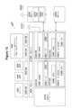
本明細書に記載される主題は、任意の適切な構成要素を用いて任意の適切なタイプのシステムで実施され得るが、本明細書に開示される実施形態は、図11に図示される例示的な無線ネットワークなどの無線ネットワークに関連して説明される。簡略化のため、図11の無線ネットワークには、ネットワーク4106、ネットワークノード4160および4160b、ならびにWD4110、4110b、および4110c(移動端末とも呼ばれる)だけが描かれている。実際には、無線ネットワークは、無線デバイス間、または無線デバイスと他の通信デバイス(固定電話、サービスプロバイダ、または他のネットワークノードもしくはエンドデバイスなど)との間の通信をサポートするのに適した任意の追加要素をさらに含んでもよい。図示された構成要素のうち、ネットワークノード4160および無線デバイス(WD)4110は、追加の詳細とともに描かれている。無線ネットワークは、無線デバイスの、無線ネットワークによって、または無線ネットワークを介して提供されるサービスへのアクセスおよび/または使用を容易にするために、通信および他のタイプのサービスを1つまたは複数の無線デバイスに提供し得る。
Although the subject matter described herein may be implemented in any suitable type of system using any suitable components, the embodiments disclosed herein may be implemented using the example illustrated in FIG. wireless networks, such as standard wireless networks. For simplicity, only
無線ネットワークは、任意のタイプの通信、テレコミュニケーション、データ、セルラー、及び/又は無線ネットワーク、又は他の同様のタイプのシステムで構成され、及び/又はそれらとインタフェースしてもよい。いくつかの実施形態では、無線ネットワークは、特定の規格または他のタイプの事前定義された規則または手順に従って動作するように構成されてもよい。したがって、無線ネットワークの特定の実施形態は、移動通信のグローバルシステム(GSM)、ユニバーサル移動通信システム(UMTS)、ロングタームエボリューション(LTE)、および/または他の適切な2G、3G、4G、または5G規格などの通信規格;IEEE802.11規格などの無線ローカルエリアネットワーク(WLAN)規格;および/またはマイクロ波アクセスのための世界相互運用性(WiMax)、Bluetooth(登録商標)、Z-Waveおよび/またはZigBee規格などの他の任意の適切な無線通信規格などを実装することができる。 A wireless network may consist of and/or interface with any type of communications, telecommunications, data, cellular, and/or wireless network, or other similar type of system. In some embodiments, a wireless network may be configured to operate according to a particular standard or other type of predefined rules or procedures. Accordingly, certain embodiments of the wireless network may include Global System for Mobile Communications (GSM), Universal Mobile Telecommunications System (UMTS), Long Term Evolution (LTE), and/or other suitable 2G, 3G, 4G, or 5G communication standards such as the Wireless Local Area Network (WLAN) standards such as the IEEE 802.11 standard; and/or Worldwide Interoperability for Microwave Access (WiMax), Bluetooth®, Z-Wave and/or Any other suitable wireless communication standard, such as the ZigBee standard, etc. may be implemented.
ネットワーク4106は、1つ以上のバックホールネットワーク、コアネットワーク、IPネットワーク、公衆交換電話網(PSTN)、パケットデータネットワーク、光ネットワーク、広域ネットワーク(WAN)、ローカルエリアネットワーク(LAN)、無線ローカルエリアネットワーク(WLAN)、有線ネットワーク、無線ネットワーク、メトロポリタンエリアネットワーク、およびデバイス間のコミュニケーションを可能にする他のネットワークから構成されてもよい。
ネットワークノード4160とWD4110は、以下により詳細に説明する様々な構成要素で構成される。これらの構成要素は、無線ネットワークにおいて無線接続を提供するなどのネットワークノードおよび/または無線デバイスの機能性を提供するために、協働する。異なる実施形態では、無線ネットワークは、有線または無線接続を介してであるかどうかにかかわらずデータおよび/またはシグナリングの通信を促進または参加し得る任意の数の有線または無線ネットワーク、ネットワークノード、基地局、コントローラ、無線デバイス、中継局、および/または任意の他の構成要素またはシステムから構成されてもよい。 Network node 4160 and WD 4110 are comprised of various components described in more detail below. These components cooperate to provide network node and/or wireless device functionality, such as providing wireless connectivity in a wireless network. In different embodiments, a wireless network includes any number of wired or wireless networks, network nodes, base stations that may facilitate or participate in the communication of data and/or signaling, whether through wired or wireless connections. , a controller, a wireless device, a relay station, and/or any other components or systems.
本明細書で使用される場合、ネットワークノードは、無線デバイスへの無線アクセスを可能にし、提供し、および/または無線ネットワーク内の他のネットワークノードまたは機器と直接または間接的に通信することができ、構成され、配置され、および/または動作可能な機器を指し、無線デバイスに無線アクセスを可能にし、および/または無線ネットワーク内の他の機能(例えば、管理)を行うことができる。ネットワークノードの例としては、アクセスポイント(AP)(例えば、無線アクセスポイント)、基地局(BS)(例えば、無線基地局、ノードB、進化型ノードB(eNB)、NRノードB(gNB))などがあるが、これらに限定されるわけではない。基地局は、それらが提供するカバレッジの量(または、別の言い方をすれば、それらの送信電力レベル)に基づいて分類されてもよく、その後、フェムト基地局、ピコ基地局、マイクロ基地局、またはマクロ基地局とも呼ばれることがある。基地局は、中継ノードであってもよいし、中継を制御する中継ドナーノードであってもよい。ネットワークノードは、集中デジタルユニットおよび/またはリモート無線ヘッド(RRH)と呼ばれることもあるリモート無線ユニット(RRU)などの分散無線基地局の1つまたは複数(またはすべて)の部分を含むこともできる。このような遠隔無線ユニットは、アンテナ一体型無線機としてアンテナと一体化されてもよいし、一体化されなくてもよい。分散型無線基地局の部品は、分散型アンテナシステム(DAS)のノードと呼ばれることもある。ネットワークノードのさらに別の例は、MSRのBSなどのマルチスタンダード無線(MSR)機器、無線ネットワークコントローラ(RNC)または基地局コントローラ(BSC)などのネットワークコントローラ、基地送受信機局(BTS)、送信点、送信ノード、マルチセル/マルチキャスト調整エンティティ(MCE)、コアネットワークノード(例えば、MSC、MME)、O&Mノード、OSSノード、SONノード、測位ノード(例えば、E-SMLC)、および/またはMDTを挙げることができる。別の例として、ネットワークノードは、以下でより詳細に説明するように、仮想ネットワークノードであってもよい。しかし、より一般的には、ネットワークノードは、無線デバイスに無線ネットワークへのアクセスを有効化および/もしくは提供すること、または無線ネットワークにアクセスした無線デバイスに何らかのサービスを提供することが可能な、構成、配置、および動作可能な任意の適切なデバイス(またはデバイスのグループ)を表すことができる。 As used herein, a network node is capable of enabling and providing wireless access to wireless devices and/or communicating directly or indirectly with other network nodes or equipment within a wireless network. Refers to equipment configured, arranged, and/or operable to provide wireless access to wireless devices and/or perform other functions (e.g., management) within a wireless network. Examples of network nodes include access points (APs) (e.g., wireless access points), base stations (BSs) (e.g., wireless base stations, Node Bs, evolved Node Bs (eNBs), NR Node Bs (gNBs)). These include, but are not limited to. Base stations may be classified based on the amount of coverage they provide (or, put another way, their transmit power level) and are then classified into femto base stations, pico base stations, micro base stations, It is also sometimes called a macro base station. The base station may be a relay node or a relay donor node that controls relaying. A network node may also include one or more (or all) parts of a distributed radio base station, such as a centralized digital unit and/or a remote radio unit (RRU), sometimes referred to as a remote radio head (RRH). Such a remote radio unit may or may not be integrated with an antenna as an integrated antenna radio. Components of a distributed radio base station are sometimes referred to as distributed antenna system (DAS) nodes. Further examples of network nodes are multi-standard radio (MSR) equipment such as an MSR's BS, a network controller such as a radio network controller (RNC) or a base station controller (BSC), a base transceiver station (BTS), a transmission point , a transmitting node, a multicell/multicast coordinating entity (MCE), a core network node (e.g., MSC, MME), an O&M node, an OSS node, a SON node, a positioning node (e.g., E-SMLC), and/or an MDT. Can be done. As another example, the network node may be a virtual network node, as described in more detail below. More generally, however, a network node is a configuration capable of enabling and/or providing wireless devices with access to a wireless network or providing some service to wireless devices that have accessed the wireless network. , arrangement, and may represent any suitable device (or group of devices) capable of operation.
図11において、ネットワークノード4160は、処理回路4170、デバイス可読媒体4180、インタフェース4190、補助装置4184、電源4186、電源回路4187、およびアンテナ4162を含む。図11の例示的な無線ネットワークに図示されたネットワークノード4160は、ハードウェア構成要素の図示された組み合わせを含む装置を表すことができるが、他の実施形態は、構成要素の異なる組み合わせを有するネットワークノードから構成されることができる。ネットワークノードは、本明細書に開示されるタスク、特徴、機能、および方法を実行するために必要なハードウェアおよび/またはソフトウェアの任意の適切な組み合わせからなることが理解されよう。さらに、ネットワークノード4160の構成要素は、より大きなボックス内に位置する単一のボックスとして、または複数のボックス内にネストされたものとして描かれているが、実際には、ネットワークノードは、単一の図示の構成要素を構成する複数の異なる物理構成要素からなる場合がある(例えば、デバイス可読媒体4180は、複数の別々のハードドライブだけでなく複数のRAMモジュールからなる場合がある)。
In FIG. 11, network node 4160 includes
同様に、ネットワークノード4160は、複数の物理的に別々の構成要素(例えば、NodeB構成要素とRNC構成要素、またはBTS構成要素とBSC構成要素など)で構成されてもよい。ネットワークノード4160が複数の別個の構成要素(例えば、BTSおよびBSC構成要素)からなる特定のシナリオでは、別個の構成要素の1つまたは複数が、複数のネットワークノード間で共有されてもよい。例えば、単一のRNCが複数のNodeBを制御する場合がある。このようなシナリオでは、それぞれのNodeBおよびRNCの組は、いくつかの実施態様では、単一の別個のネットワークノードと見なされてもよい。いくつかの実施形態において、ネットワークノード4160は、複数の無線アクセス技術(RAT)をサポートするように構成されてもよい。そのような実施形態では、一部の構成要素は重複してもよく(例えば、異なるRATのための別々のデバイス可読媒体4180)、一部の構成要素は再利用されてもよい(例えば、同じアンテナ4162がRATによって共有されてもよい)。ネットワークノード4160はまた、例えばGSM、WCDMA、LTE、NR、WiFi、またはBluetooth無線技術など、ネットワークノード4160に統合された異なる無線技術用の様々な図示の構成要素の複数のセットを含んでもよい。これらの無線技術は、ネットワークノード4160内の同一または異なるチップまたはチップのセットおよび他の構成要素に統合されてもよい。
Similarly, network node 4160 may be comprised of multiple physically separate components (eg, NodeB and RNC components, or BTS and BSC components, etc.). In certain scenarios where network node 4160 consists of multiple separate components (eg, BTS and BSC components), one or more of the separate components may be shared among multiple network nodes. For example, a single RNC may control multiple NodeBs. In such a scenario, each NodeB and RNC pair may be considered a single, separate network node in some implementations. In some embodiments, network node 4160 may be configured to support multiple radio access technologies (RATs). In such embodiments, some components may be duplicated (e.g., separate device-readable media 4180 for different RATs) and some components may be reused (e.g., the same (
処理回路4170は、ネットワークノードによって提供されるものとして本明細書で説明される任意の決定、計算、または同様の操作(例えば、特定の取得操作)を実行するように構成される。処理回路4170によって実行されるこれらの動作は、例えば、得られた情報を他の情報に変換すること、得られた情報または変換された情報をネットワークノードに格納された情報と比較すること、および/または得られた情報または変換された情報に基づいて1つまたは複数の動作を実行すること、および処理の結果として判定を行うことによって処理回路4170によって得られた情報を処理することを含んでもよい。
処理回路4170は、マイクロプロセッサ、コントローラ、マイクロコントローラ、中央処理装置、デジタル信号プロセッサ、特定用途向け集積回路、フィールドプログラマブルゲートアレイ、または他の任意の適切なコンピューティング装置、リソース、または単独または装置可読媒体4180などの他のネットワークノード4160構成要素と組み合わせてネットワークノード4160機能を提供するように動作可能なハードウェア、ソフトウェアおよび/または符号化論理の1以上の組み合わせからなる場合がある。例えば、処理回路4170は、デバイス可読媒体4180または処理回路4170内のメモリに格納された命令を実行することができる。そのような機能性は、本明細書で議論される様々な無線特徴、機能、または利点のいずれかを提供することを含んでもよい。いくつかの実施形態において、処理回路4170は、システムオンチップ(SOC)を含んでもよい。
いくつかの実施形態では、処理回路4170は、無線周波数(RF)送受信機回路4172およびベースバンド処理回路4174のうちの1つまたは複数を含んでもよい。いくつかの実施形態において、無線周波数(RF)送受信機回路4172およびベースバンド処理回路4174は、無線ユニットおよびデジタルユニットなどの別々のチップ(またはチップのセット)、基板、またはユニット上にあってもよい。代替の実施形態では、RF送受信機回路4172及びベースバンド処理回路4174の一部又は全部は、同じチップ又はチップのセット、ボード、又はユニット上にあってもよい。
In some embodiments,
特定の実施形態では、ネットワークノード、基地局、eNB、または他のそのようなネットワークデバイスによって提供されるものとして本明細書に記載される機能性の一部またはすべては、処理回路4170がデバイス可読媒体4180または処理回路4170内のメモリに格納された命令を実行することによって実行されてもよい。代替の実施形態では、機能の一部または全部は、ハードワイヤード方式など、別個のまたは個別のデバイス可読媒体に格納された命令を実行することなく、処理回路4170によって提供されてもよい。それらの実施形態のいずれにおいても、デバイス可読記憶媒体上に記憶された命令を実行するか否かにかかわらず、処理回路4170は、説明された機能性を実行するように構成され得る。そのような機能性によって提供される利点は、処理回路4170だけに、またはネットワークノード4160の他の構成要素に限定されず、ネットワークノード4160全体によって、および/またはエンドユーザおよび無線ネットワークによって一般に享受される。
In certain embodiments, some or all of the functionality described herein as provided by a network node, base station, eNB, or other such network device may be implemented by processing
デバイス可読媒体4180は、限定されないが、永続的ストレージ、ソリッドステートメモリ、リモートマウントメモリ、磁気媒体、光媒体、ランダムアクセスメモリ(RAM)、リードオンリーメモリ(ROM)、大容量記憶媒体(例えば、ハードディスク)などを含む揮発または不揮発性のコンピュータ可読メモリの任意の形態からなることができる。リムーバブル記憶媒体(例えば、フラッシュドライブ、コンパクトディスク(CD)またはデジタルビデオディスク(DVD))、および/または処理回路4170によって使用され得る情報、データ、および/または命令を格納する他の任意の揮発性または非揮発性の、非一時的のデバイス可読および/またはコンピュータ実行可能メモリデバイスである。デバイス可読媒体4180は、コンピュータプログラム、ソフトウェア、論理、規則、コード、テーブルなどのうちの1つ以上を含むアプリケーション、および/または処理回路4170によって実行可能で、ネットワークノード4160によって利用される他の命令を含む任意の適切な命令、データまたは情報を格納してもよい。デバイス可読媒体4180は、処理回路4170によって行われた任意の計算、および/またはインタフェース4190を介して受信された任意のデータを格納するために使用されてもよい。いくつかの実施形態では、処理回路4170およびデバイス可読媒体4180は、統合されていると考えてもよい。
Device readable media 4180 includes, but is not limited to, persistent storage, solid state memory, remotely mounted memory, magnetic media, optical media, random access memory (RAM), read only memory (ROM), mass storage media (e.g., hard disk ), etc., may consist of any form of computer readable memory, volatile or non-volatile. A removable storage medium (e.g., a flash drive, a compact disc (CD) or a digital video disc (DVD)), and/or any other volatile device that stores information, data, and/or instructions that may be used by processing
インタフェース4190は、ネットワークノード4160、ネットワーク4106、及び/又はWD4110間のシグナリング及び/又はデータの有線又は無線通信に使用される。図示されているように、インタフェース4190は、例えば有線接続を介してネットワーク4106との間でデータを送受信するためのポート(複数可)/端子4194を含んでいる。インタフェース4190はまた、アンテナ4162に結合され得る、又は特定の実施形態においてアンテナ4162の一部である無線フロントエンド回路4192を含む。無線フロントエンド回路4192は、フィルタ4198及び増幅器4196からなる。無線フロントエンド回路4192は、アンテナ4162および処理回路4170に接続されてもよい。無線フロントエンド回路は、アンテナ4162と処理回路4170との間で通信される信号を条件付けるように構成されてもよい。無線フロントエンド回路4192は、無線接続を介して他のネットワークノードまたはWDに送り出されることになるデジタルデータを受信してもよい。無線フロントエンド回路4192は、フィルタ4198および/または増幅器4196の組み合わせを使用して、デジタルデータを、適切なチャネルおよび帯域幅パラメータを有する無線信号に変換してもよい。その後、無線信号は、アンテナ4162を介して送信されてもよい。同様に、データを受信するとき、アンテナ4162は、無線フロントエンド回路4192によってデジタルデータに変換された無線信号を収集してもよい。デジタルデータは、処理回路4170に渡されてもよい。他の実施形態では、インタフェースは、異なる構成要素及び/又は構成要素の異なる組合せから構成されてもよい。
特定の代替実施形態では、ネットワークノード4160は、別個の無線フロントエンド回路4192を含まなくてもよく、代わりに、処理回路4170は、無線フロントエンド回路を構成してもよく、別個の無線フロントエンド回路4192なしでアンテナ4162に接続されてもよい。同様に、いくつかの実施形態では、RF送受信機回路4172のすべてまたは一部は、インタフェース4190の一部と見なされてもよい。さらに他の実施形態では、インタフェース4190は、無線ユニット(図示せず)の一部として、1つまたは複数のポートまたは端子4194、無線フロントエンド回路4192、およびRF送受信機回路4172を含んでもよく、インタフェース4190は、デジタルユニット(図示せず)の一部であるベースバンド処理回路4174と通信していてもよい。
In certain alternative embodiments, the network node 4160 may not include a separate wireless front end circuit 4192; instead, the
アンテナ4162は、無線信号を送信および/または受信するように構成された1つまたは複数のアンテナ、またはアンテナアレイを含んでもよい。アンテナ4162は、無線フロントエンド回路4192に結合されてもよく、データ及び/又は信号を無線で送受信することができる任意のタイプのアンテナであってもよい。いくつかの実施形態では、アンテナ4162は、例えば、2GHzと66GHzとの間で無線信号を送受信するように動作可能な1つ以上の全方向性アンテナ、セクタアンテナ、またはパネルアンテナを含んでいてよい。全方向性アンテナは、任意の方向に無線信号を送信/受信するために使用されてもよく、セクタアンテナは、特定の領域内のデバイスから無線信号を送信/受信するために使用されてもよく、パネルアンテナは、比較的直線的に無線信号を送信/受信するために使用されるラインオブサイトアンテナであってもよい。いくつかの実施形態では、複数のアンテナの使用は、MIMOと呼ばれることがある。特定の実施形態では、アンテナ4162は、ネットワークノード4160とは別個であってもよく、インタフェース又はポートを介してネットワークノード4160に接続可能であってもよい。
アンテナ4162、インタフェース4190、および/または処理回路4170は、ネットワークノードによって実行されるものとして本明細書に記載される任意の受信動作および/または特定の取得動作を実行するように構成され得る。任意の情報、データ、および/または信号は、無線デバイス、別のネットワークノード、および/または任意の他のネットワーク機器から受信されてもよい。同様に、アンテナ4162、インタフェース4190、および/または処理回路4170は、ネットワークノードによって実行されるものとして本明細書に記載される任意の送信動作を実行するように構成されてもよい。任意の情報、データおよび/または信号が、無線デバイス、別のネットワークノードおよび/または任意の他のネットワーク機器に送信されてもよい。
電源回路4187は、電源管理回路からなるか、または電源管理回路に結合されてもよく、本明細書に記載される機能を実行するための電力をネットワークノード4160の構成要素に供給するように構成される。電力回路4187は、電源4186から電力を受信してもよい。電源4186および/または電力回路4187は、それぞれの構成要素に適した形態で(例えば、それぞれの構成要素に必要な電圧および電流レベルで)ネットワークノード4160の様々な構成要素に電力を供給するよう構成されてもよい。電源4186は、電源回路4187および/またはネットワークノード4160に含まれるか、または外付けされるかのいずれかであってよい。例えば、ネットワークノード4160は、電気ケーブルなどの入力回路またはインタフェースを介して外部電源(例えば、電気コンセント)に接続可能であってもよく、それによって、外部電源は電源回路4187に電力を供給する。さらなる例として、電源4186は、電源回路4187に接続されるか、または電源回路4187に統合される電池または電池パックの形態の電力源から構成されてもよい。バッテリは、外部電源が故障した場合にバックアップ電力を提供してもよい。光起電力装置などの他のタイプの電源も使用することができる。
ネットワークノード4160の代替実施形態は、本明細書に記載される機能のいずれかおよび/または本明細書に記載される主題をサポートするために必要な機能を含むネットワークノードの機能の特定の側面を提供する役割を担う、図11に示すもの以外の追加の構成要素を含んでもよい。例えば、ネットワークノード4160は、ネットワークノード4160への情報の入力を可能にし、ネットワークノード4160からの情報の出力を可能にするためのユーザインタフェース装置を含んでもよい。これにより、ユーザは、ネットワークノード4160の診断、保守、修理、および他の管理機能を実行することができる。 Alternative embodiments of network node 4160 may implement certain aspects of the functionality of the network node, including any of the functionality described herein and/or functionality necessary to support the subject matter described herein. Additional components other than those shown in FIG. 11 may be included that play a role in providing information. For example, network node 4160 may include a user interface device to enable information to be input to network node 4160 and to enable information to be output from network node 4160. This allows users to perform diagnostics, maintenance, repair, and other management functions on network node 4160.
本明細書で使用される場合、無線デバイス(WD)は、ネットワークノードおよび/または他の無線デバイスと無線通信することができ、構成され、配置され、および/または動作可能なデバイスを意味する。特に断りのない限り、本明細書では、WDという用語はユーザ装置(UE)と互換的に使用される場合がある。無線で通信することは、電磁波、電波、赤外線、および/またはエアを通して情報を伝達するのに適した他のタイプの信号を用いて無線信号を送信および/または受信することを含み得る。いくつかの実施形態では、WDは、人間の直接的な相互作用なしに情報を送信および/または受信するように構成されてもよい。例えば、WDは、所定のスケジュールで、内部または外部のイベントによってトリガされたときに、またはネットワークからの要求に応答して、ネットワークに情報を送信するように設計されてもよい。WDの例としては、スマートフォン、携帯電話、セルラー電話、ボイスオーバーIP(VoIP)電話、無線ローカルループ電話、デスクトップコンピュータ、パーソナルデジタルアシスタント(PDA)、無線カメラ、ゲーム機または装置、音楽ストレージ装置、再生装置、ウェアラブル端末装置、無線エンドポイント、モバイルステーション、タブレット、ラップトップ、ラップトップ内蔵装置(LEE)、ラップトップ搭載装置(LME)、スマートデバイス、無線顧客宅内装置(CPE)、車載型無線端末装置などが挙げられるが、これらに限定されるものではない。WDは、例えば、サイドリンク通信、車両間通信(V2V)、車両対インフラストラクチャ(V2I)、車両対任意物通信(V2X)のための3GPP規格を実装することによって、デバイス間通信(D2D)をサポートしてもよく、この場合、D2D通信装置と呼ばれてもよい。さらに他の具体例として、モノのインターネット(IoT)シナリオにおいて、WDは、監視および/または測定を実行し、そのような監視および/または測定の結果を他のWDおよび/またはネットワークノードに送信する機械または他の装置を表してもよい。この場合、WDは、3GPPの文脈ではMTCデバイスと呼ばれるマシンツーマシン(M2M)デバイスであってもよい。特定の例として、WDは、3GPPのナローバンドインターネットオブシングス(NB-IoT)標準を実装したUEであり得る。このような機械または装置の特に例としては、センサー、電力計などの計量装置、産業機械、または家庭用または個人用の電化製品(冷蔵庫、テレビなど)個人用ウェアラブル(時計、フィットネストラッカーなど)がある。他の態様では、WDは、その動作状態またはその動作に関連する他の機能を監視および/または報告することができる車両または他の装置を表してもよい。上述のようなWDは、無線接続のエンドポイントを表してもよく、この場合、装置は無線端末と呼ばれてもよい。さらに、上述したようなWDは、移動可能であってもよく、その場合には、移動装置または移動端末と呼ばれてもよい。 As used herein, wireless device (WD) refers to a device capable of, configured, arranged, and/or operable to communicate wirelessly with network nodes and/or other wireless devices. Unless otherwise specified, the term WD may be used interchangeably with user equipment (UE) herein. Communicating wirelessly may include sending and/or receiving wireless signals using electromagnetic waves, radio waves, infrared radiation, and/or other types of signals suitable for conveying information over the air. In some embodiments, a WD may be configured to send and/or receive information without direct human interaction. For example, the WD may be designed to send information to the network on a predetermined schedule, when triggered by an internal or external event, or in response to a request from the network. Examples of WD include smartphones, mobile phones, cellular phones, voice over IP (VoIP) phones, wireless local loop phones, desktop computers, personal digital assistants (PDAs), wireless cameras, gaming consoles or devices, music storage devices, playback equipment, wearable terminal equipment, wireless endpoints, mobile stations, tablets, laptops, laptop embedded equipment (LEE), laptop embedded equipment (LME), smart devices, wireless customer premise equipment (CPE), vehicle-mounted wireless terminal equipment Examples include, but are not limited to, the following. WD supports device-to-device communications (D2D) by implementing, for example, 3GPP standards for sidelink communications, vehicle-to-vehicle communications (V2V), vehicle-to-infrastructure (V2I), and vehicle-to-anything communications (V2X). may be supported, in which case it may be referred to as a D2D communication device. As yet another example, in an Internet of Things (IoT) scenario, a WD performs monitoring and/or measurements and transmits the results of such monitoring and/or measurements to other WDs and/or network nodes. May also represent a machine or other device. In this case, the WD may be a machine-to-machine (M2M) device, referred to as an MTC device in the context of 3GPP. As a particular example, the WD may be a UE implementing the 3GPP Narrowband Internet of Things (NB-IoT) standard. Particular examples of such machines or devices include sensors, metering devices such as power meters, industrial machinery, or household or personal appliances (refrigerators, televisions, etc.) personal wearables (watches, fitness trackers, etc.). be. In other aspects, a WD may represent a vehicle or other device that can monitor and/or report its operating status or other features related to its operation. A WD as described above may represent an endpoint of a wireless connection, in which case the device may be referred to as a wireless terminal. Additionally, a WD as described above may be mobile, in which case it may be referred to as a mobile device or mobile terminal.
図示されているように、無線デバイス4110は、アンテナ4111、インタフェース4114、処理回路4120、デバイス可読媒体4130、ユーザインタフェース装置4132、補助装置4134、電源4136、および電源回路4137を含む。WD4110は、例えば、ほんの数例を挙げると、GSM、WCDMA、LTE、NR、WiFi、WiMAX、またはBluetooth無線技術などのWD4110によってサポートされる異なる無線技術用の図示の構成要素のうちの1以上の複数のセットを含んでもよい。これらの無線技術は、WD4110内の他の構成要素と同じまたは異なるチップまたはチップのセットに統合されてもよい。
As shown, wireless device 4110 includes an
アンテナ4111は、無線信号を送信及び/又は受信するように構成された、1つ又は複数のアンテナ又はアンテナアレイを含んでもよく、インタフェース4114に接続される。特定の代替的な実施形態において、アンテナ4111は、WD4110とは別個であってよく、インタフェースまたはポートを介してWD4110に接続可能であってよい。アンテナ4111、インタフェース4114、および/または処理回路4120は、WDによって実行されるものとして本明細書で説明される任意の受信または送信動作を実行するように構成されてもよい。任意の情報、データおよび/または信号は、ネットワークノードおよび/または別のWDから受信されてもよい。いくつかの実施形態において、無線フロントエンド回路および/またはアンテナ4111は、インタフェースと見なされ得る。
図示するように、インタフェース4114は、無線フロントエンド回路4112とアンテナ4111から構成される。無線フロントエンド回路4112は、1つまたは複数のフィルタ4118および増幅器4116から構成される。無線フロントエンド回路4112は、アンテナ4111および処理回路4120に接続され、アンテナ4111と処理回路4120との間で通信される信号を調整するように構成される。無線フロントエンド回路4112は、アンテナ4111に結合されてもよいし、アンテナ4111の一部であってもよい。いくつかの実施形態において、WD4110は、別個の無線フロントエンド回路4112を含まなくてもよく、むしろ、処理回路4120は、無線フロントエンド回路を構成してもよく、アンテナ4111に接続されてもよい。同様に、いくつかの実施形態において、RF送受信機回路4122の一部または全部は、インタフェース4114の一部と見なされてもよい。無線フロントエンド回路4112は、無線接続を介して他のネットワークノードまたはWDに送出されるべきデジタルデータを受信してもよい。無線フロントエンド回路4112は、フィルタ4118および/または増幅器4116の組み合わせを使用して、デジタルデータを、適切なチャネルおよび帯域幅パラメータを有する無線信号に変換してもよい。その後、無線信号は、アンテナ4111を介して送信されてもよい。同様に、データを受信するとき、アンテナ4111は、無線フロントエンド回路4112によってデジタルデータに変換された無線信号を収集してもよい。デジタルデータは、処理回路4120に渡されてもよい。他の実施形態では、インタフェースは、異なる構成要素及び/又は構成要素の異なる組合せから構成されてもよい。
As shown, the interface 4114 includes a wireless
処理回路4120は、マイクロプロセッサ、コントローラ、マイクロコントローラ、中央処理装置、デジタル信号プロセッサ、特定用途向け集積回路、フィールドプログラマブルゲートアレイ、または他の任意の適切なコンピューティング装置、リソース、またはデバイス可読媒体4130などの他のWD4110構成要素と組み合わせてWD4110機能を単独または提供して動作可能なハードウェア、ソフトウェア、および/または符号化論理の1以上の組み合わせからなることができる。そのような機能性は、本明細書で議論される様々な無線特徴または利点のいずれかを提供することを含み得る。例えば、処理回路4120は、デバイス可読媒体4130または処理回路4120内のメモリに格納された命令を実行して、本明細書で開示される機能性を提供してもよい。 Processing circuitry 4120 may include a microprocessor, controller, microcontroller, central processing unit, digital signal processor, application specific integrated circuit, field programmable gate array, or any other suitable computing device, resource, or device readable medium 4130 It may consist of one or more combinations of hardware, software, and/or encoding logic operable alone or providing WD4110 functionality in combination with other WD4110 components, such as. Such functionality may include providing any of the various wireless features or benefits discussed herein. For example, processing circuitry 4120 may execute instructions stored on device readable medium 4130 or memory within processing circuitry 4120 to provide the functionality disclosed herein.
図示されているように、処理回路4120は、RF送受信機回路4122、ベースバンド処理回路4124、およびアプリケーション処理回路4126のうちの1つまたは複数を含む。他の実施形態では、処理回路は、異なる構成要素及び/又は構成要素の異なる組合せから構成されてもよい。特定の実施形態において、WD4110の処理回路4120は、SOCから構成されてもよい。いくつかの実施形態において、RF送受信機回路4122、ベースバンド処理回路4124、およびアプリケーション処理回路4126は、別々のチップまたはチップのセット上にあってもよい。代替の実施形態において、ベースバンド処理回路4124およびアプリケーション処理回路4126の一部または全部は、1つのチップまたはチップのセットに結合されてもよく、RF送受信機回路4122は、別々のチップまたはチップのセット上にあってもよい。さらに代替的な実施形態では、RF送受信機回路4122およびベースバンド処理回路4124の一部または全部は、同じチップまたはチップのセット上にあってもよく、アプリケーション処理回路4126は、別のチップまたはチップのセット上にあってもよい。さらに他の代替的な実施形態では、RF送受信機回路4122、ベースバンド処理回路4124、およびアプリケーション処理回路4126の一部または全部は、同じチップまたはチップのセットに組み合わされてもよい。いくつかの実施形態では、RF送受信機回路4122は、インタフェース4114の一部であってよい。RF送受信機回路4122は、処理回路4120のためにRF信号を調整してもよい。
As shown, processing circuitry 4120 includes one or more of
特定の実施形態において、WDによって実行されるとして本明細書において説明される機能性の一部またはすべては、特定の実施形態においてコンピュータ可読記憶媒体であってよいデバイス可読媒体4130上に記憶された命令を実行する処理回路4120によって提供されてもよい。代替の実施形態では、機能の一部または全部は、ハードワイヤード方式など、別個または個別のデバイス可読記憶媒体に記憶された命令を実行することなく、処理回路4120によって提供されてもよい。それらの特定の実施形態のいずれにおいても、デバイス可読記憶媒体上に記憶された命令を実行するか否かにかかわらず、処理回路4120は、説明された機能性を実行するように構成され得る。そのような機能性によって提供される利点は、処理回路4120だけに、またはWD4110の他の構成要素に限定されず、WD4110全体によって、および/またはエンドユーザおよび無線ネットワークによって一般に享受される。 In certain embodiments, some or all of the functionality described herein as being performed by a WD is stored on device readable medium 4130, which in certain embodiments may be a computer readable storage medium. It may be provided by processing circuitry 4120 that executes the instructions. In alternative embodiments, some or all of the functionality may be provided by processing circuitry 4120 without executing instructions stored on a separate or separate device-readable storage medium, such as in a hard-wired manner. In any of these particular embodiments, processing circuitry 4120 may be configured to perform the described functionality whether or not executing instructions stored on a device-readable storage medium. The benefits provided by such functionality are not limited to processing circuitry 4120 or other components of WD 4110, but are generally enjoyed by WD 4110 as a whole and/or by end users and wireless networks.
処理回路4120は、WDによって実行されるものとして本明細書で説明される任意の決定、計算、または同様の操作(例えば、特定の取得操作)を実行するように構成されてもよい。処理回路4120によって実行されるこれらの動作は、例えば、得られた情報を他の情報に変換すること、得られた情報または変換された情報をWD4110によって記憶された情報と比較すること、および/または得られた情報または変換された情報に基づいて1つまたは複数の動作を実行し、処理の結果として決定を行うことによって処理回路4120によって得られた情報を処理することを含むことができる。 Processing circuitry 4120 may be configured to perform any determinations, calculations, or similar operations described herein as being performed by a WD (eg, certain acquisition operations). These operations performed by processing circuitry 4120 include, for example, converting the obtained information into other information, comparing the obtained or transformed information with information stored by WD 4110, and/or or processing the information obtained by processing circuitry 4120 by performing one or more operations based on the obtained or transformed information and making decisions as a result of the processing.
デバイス可読媒体4130は、コンピュータプログラム、ソフトウェア、論理、規則、コード、テーブル等のうちの1つ以上を含むアプリケーション、及び/又は処理回路4120によって実行することができる他の命令を格納するように動作可能であってよい。デバイス可読媒体4130は、コンピュータメモリ(例えば、ランダムアクセスメモリ(RAM)またはリードオンリーメモリ(ROM))、大容量記憶媒体(例えば、ハードディスク)、取り外し可能な記憶媒体(例えば、コンパクトディスク(CD)またはデジタルビデオディスク(DVD))、及び/または処理回路4120によって使用され得る情報、データ、及び/または命令を記憶する他の任意の揮発性または不揮発性の、非一時的デバイス可読及び/またはコンピュータ実行可能メモリデバイスを含み得る。いくつかの実施形態では、処理回路4120およびデバイス可読媒体4130は、統合されていると考えてもよい。 Device readable medium 4130 is operative to store applications including one or more of computer programs, software, logic, rules, code, tables, etc., and/or other instructions that can be executed by processing circuitry 4120. It may be possible. Device readable medium 4130 can include computer memory (e.g., random access memory (RAM) or read-only memory (ROM)), mass storage media (e.g., hard disk), removable storage media (e.g., compact disk (CD), or digital video disc (DVD)) and/or any other volatile or non-volatile, non-transitory device readable and/or computer-implemented that stores information, data, and/or instructions that may be used by processing circuitry 4120 memory devices. In some embodiments, processing circuitry 4120 and device readable medium 4130 may be considered integrated.
ユーザインタフェース装置4132は、人間のユーザがWD4110と相互作用することを可能にする構成要素を提供し得る。そのような相互作用は、視覚、聴覚、触覚など、多くの形態であってよい。ユーザインタフェース装置4132は、ユーザに対する出力を生成し、ユーザがWD4110に入力を提供することを可能にするように動作可能であってよい。相互作用の種類は、WD4110に設置されたユーザインタフェース装置4132の種類によって異なってもよい。例えば、WD4110がスマートフォンである場合、対話はタッチスクリーンを介していてもよく、WD4110がスマートメーターである場合、対話は使用量(例えば、使用ガロン数)を提供するスクリーンまたは可聴警報を提供するスピーカー(例えば、煙が検出された場合)を介していてよい。ユーザインタフェース装置4132は、入力インタフェース、デバイス及び回路、並びに出力インタフェース、デバイス及び回路を含んでもよい。ユーザインタフェース装置4132は、WD4110への情報の入力を可能にするように構成され、処理回路4120に接続されて、処理回路4120が入力情報を処理することを可能にする。ユーザインタフェース装置4132は、例えば、マイクロフォン、近接または他のセンサ、キー/ボタン、タッチディスプレイ、1つまたは複数のカメラ、USBポート、または他の入力回路を含んでもよい。ユーザインタフェース装置4132はまた、WD4110からの情報の出力を可能にし、処理回路4120がWD4110から情報を出力することを可能にするように構成される。ユーザインタフェース装置4132は、例えば、スピーカ、ディスプレイ、振動回路、USBポート、ヘッドフォンインタフェース、又は他の出力回路を含んでもよい。ユーザインタフェース装置4132の1つ以上の入力および出力インタフェース、デバイス、および回路を使用して、WD4110は、エンドユーザおよび/または無線ネットワークと通信し、それらが本明細書に記載される機能から恩恵を受けることを可能にし得る。
補助装置4134は、一般的にWDによって実行されないかもしれない、より特定の機能を提供するために動作可能である。これは、様々な目的のために測定を行うための特殊なセンサ、有線通信などの追加のタイプの通信のためのインタフェースなどで構成されてもよい。補助装置4134の構成要素の包含およびタイプは、実施形態および/またはシナリオに依存して変化し得る。 Auxiliary devices 4134 are operable to provide more specific functions that may not generally be performed by the WD. This may consist of specialized sensors for taking measurements for various purposes, interfaces for additional types of communication such as wired communication, etc. The inclusion and type of components of auxiliary device 4134 may vary depending on the embodiment and/or scenario.
電源4136は、いくつかの実施形態において、バッテリー又はバッテリーパックの形態であってよい。外部電源(例えば、電気コンセント)、光起電力装置または電力セルなどの他のタイプの電源も使用されてもよい。WD4110は、本明細書で説明または示される任意の機能を実行するために電源4136からの電力を必要とするWD4110の様々な部分に電源4136から電力を供給するための電力回路4137をさらに含んでいてもよい。電力回路4137は、特定の実施形態において、電力管理回路を含んでいてよい。電源回路4137は、追加的にまたは代替的に、外部電源から電力を受け取るように動作可能であってもよく、この場合、WD4110は、入力回路または電力ケーブルなどのインタフェースを介して外部電源(電気コンセントなど)に接続可能であってもよい。電源回路4137はまた、特定の実施形態において、外部電源から電源4136に電力を供給するように動作可能であってよい。これは、例えば、電源4136の充電のためであってもよい。電源回路4137は、電力が供給されるWD4110のそれぞれの構成要素に適した電力にするために、電源4136からの電力に対して任意のフォーマット化、変換、または他の修正を実行してもよい。
Power source 4136 may be in the form of a battery or battery pack in some embodiments. Other types of power sources may also be used, such as an external power source (eg, an electrical outlet), a photovoltaic device, or a power cell. WD 4110 further includes
図12は、いくつかの実施形態によるユーザ装置を示す図である。 FIG. 12 is a diagram illustrating user equipment according to some embodiments.
図12は、本明細書で説明される様々な態様に従ったUEの一実施形態を示す図である。本明細書で使用されるように、ユーザ装置またはUEは、関連するデバイスを所有および/または操作する人間のユーザという意味でのユーザを必ずしも有していなくてもよい。その代わりに、UEは、人間のユーザへの販売または人間による操作を意図しているが、特定の人間のユーザと関連付けられていなくてもよい、または最初は関連付けられていなくてもよい装置(例えば、スマートスプリンクラー制御装置)を表すことができる。あるいは、UEは、エンドユーザへの販売またはエンドユーザによる操作を意図していないが、ユーザの利益のために関連付けられまたは操作され得るデバイス(例えば、スマート電力計)を表してもよい。UE4200は、NB-IoTのUE、マシンタイプ通信(MTC)UE、および/または拡張MTC(eMTC)UEを含む、第3世代パートナーシッププロジェクト(3GPP)により識別される任意のUEであり得る。図12に示されるように、UE4200は、3GPPのGSM、UMTS、LTE、および/または5G規格などの、3GPP(第3世代パートナーシッププロジェクト)によって公布された1つまたは複数の通信規格に従って通信するように構成されたWDの一例である。前述したように、WDとUEという用語は、互換性を持って使用されることがある。したがって、図12はUEであるが、本明細書で議論される構成要素はWDに等しく適用可能であり、その逆もまた然りである。
FIG. 12 is an illustration of one embodiment of a UE in accordance with various aspects described herein. As used herein, a user equipment or UE does not necessarily have a user in the sense of a human user who owns and/or operates the associated device. Instead, a UE is a device (such as a For example, a smart sprinkler controller). Alternatively, a UE may represent a device (e.g., a smart power meter) that is not intended for sale to or operation by an end user, but may be associated with or operated for the benefit of the user.
図12において、UE4200は、入力/出力インタフェース4205、無線周波数(RF)インタフェース4209、ネットワーク接続インタフェース4211、ランダムアクセスメモリ(RAM)4217、読み取り専用メモリ(ROM)4219および記憶媒体4221などを含むメモリ4215、通信サブシステム4231、電源4213、および/またはその他の構成要素、またはそれらの任意の組み合わせに操作可能に結合されている処理回路4201を含む。記憶媒体4221は、オペレーティングシステム4223、アプリケーションプログラム4225、およびデータ4227を含む。他の実施形態では、記憶媒体4221は、他の同様のタイプの情報を含んでもよい。特定のUEは、図12に示される構成要素のすべてを利用してもよいし、構成要素のサブセットのみを利用してもよい。構成要素間の統合のレベルは、あるUEから別のUEまで異なってもよい。さらに、特定のUEは、複数のプロセッサ、メモリ、送受信機、送信機、受信機など、構成要素の複数のインスタンスを含んでいてもよい。
In FIG. 12, the
図12において、処理回路4201は、コンピュータ命令およびデータを処理するように構成されてもよい。処理回路4201は、1つ以上のハードウェア実装ステートマシン(例えば、ディスクリートロジック、FPGA、ASICなど);適切なファームウェアとともにプログラマブルロジック;適切なソフトウェアとともにマイクロプロセッサまたはデジタル信号プロセッサ(DSP)などの1つ以上の格納プログラム、汎用プロセッサ;または上記の任意の組み合わせなどのメモリにマシン可読コンピュータプログラムとして格納されたマシン命令を実行するように動作する任意の逐次ステートマシンを実装するように構成されていても良い。例えば、処理回路4201は、2つの中央処理装置(CPU)を含んでもよい。データは、コンピュータによる使用に適した形式の情報であってもよい。
In FIG. 12,
描かれた実施形態では、入力/出力インタフェース4205は、入力デバイス、出力デバイス、または入力および出力デバイスへの通信インタフェースを提供するように構成されてもよい。UE4200は、入力/出力インタフェース4205を介して出力デバイスを使用するように構成されてもよい。出力デバイスは、入力デバイスと同じタイプのインタフェースポートを使用してもよい。例えば、USBポートは、UE4200への入力およびUE4200からの出力を提供するために使用されてもよい。出力デバイスは、スピーカ、サウンドカード、ビデオカード、ディスプレイ、モニタ、プリンタ、アクチュエータ、エミッタ、スマートカード、別の出力デバイス、またはそれらの任意の組合せであってもよい。UE4200は、入力/出力インタフェース4205を介して入力デバイスを使用し、ユーザがUE4200に情報を取り込むことができるように構成されてもよい。入力デバイスは、タッチセンシティブまたはプレゼンスセンシティブディスプレイ、カメラ(例えば、デジタルカメラ、デジタルビデオカメラ、ウェブカメラなど)、マイクロフォン、センサー、マウス、トラックボール、方向パッド、トラックパッド、スクロールホイール、スマートカードなどを含んでもよい。プレゼンスセンシティブディスプレイは、ユーザからの入力を感知するための静電容量式又は抵抗膜式のタッチセンサを含んでもよい。センサは、例えば、加速度センサ、ジャイロスコープ、傾斜センサ、力センサ、磁力計、光学センサ、近接センサ、別の同種センサ、またはそれらの任意の組合せであってもよい。例えば、入力デバイスは、加速度計、地磁気センサ、デジタルカメラ、マイクロフォン、及び光学センサであってもよい。
In the depicted embodiment, input/
図12において、RFインタフェース4209は、送信機、受信機、及びアンテナなどのRF構成要素への通信インタフェースを提供するように構成されてもよい。ネットワーク接続インタフェース4211は、ネットワーク4243aへの通信インタフェースを提供するように構成されてもよい。ネットワーク4243aは、ローカルエリアネットワーク(LAN)、ワイドエリアネットワーク(WAN)、コンピュータネットワーク、無線ネットワーク、電気通信ネットワーク、別の同種ネットワーク、またはそれらの任意の組み合わせなどの有線および/または無線ネットワークを包含してよい。例えば、ネットワーク4243aは、Wi-Fiネットワークから構成されてもよい。ネットワーク接続インタフェース4211は、イーサネット、TCP/IP、SONET、ATMなどの1つ以上の通信プロトコルに従って通信ネットワークを介して1つ以上の他のデバイスと通信するために用いられる受信機及び送信機インタフェースを含むように構成されてもよい。ネットワーク接続インタフェース4211は、通信ネットワークリンク(例えば、光、電気など)に適した受信機および送信機機能を実施してもよい。送信機及び受信機の機能は、回路部品、ソフトウェア又はファームウェアを共有してもよく、あるいは、別個に実施してもよい。
In FIG. 12,
RAM4217は、オペレーティングシステム、アプリケーションプログラム、およびデバイスドライバなどのソフトウェアプログラムの実行中にデータまたはコンピュータ命令のストレージまたはキャッシングを提供するために、処理回路4201にバス4202を介してインタフェースするように構成されてもよい。ROM4219は、処理回路4201にコンピュータ命令またはデータを提供するように構成されてもよい。例えば、ROM4219は、不揮発性メモリに格納される基本入出力(I/O)、起動、またはキーボードからのキーストロークの受信などの基本システム機能に関する不変の低レベルシステムコードまたはデータを格納するように構成されてもよい。記憶媒体4221は、RAM、ROM、プログラマブル読み取り専用メモリ(PROM)、消去可能プログラマブル読み取り専用メモリ(EPROM)、電気的消去可能プログラマブル読み取り専用メモリ(EEPROM)、磁気ディスク、光ディスク、フロッピーディスク、ハードディスク、取り外し可能カートリッジまたはフラッシュドライブなどのメモリを含むよう構成されるとよい。一例では、記憶媒体4221は、オペレーティングシステム4223、ウェブブラウザアプリケーション、ウィジェットまたはガジェットエンジンまたは他のアプリケーションなどのアプリケーションプログラム4225、およびデータファイル4227を含むよう構成されてもよい。記憶媒体4221は、UE4200による使用のために、様々な様々なオペレーティングシステムまたはオペレーティングシステムの組み合わせのいずれかを記憶してもよい。
記憶媒体4221は、多数の物理ドライブユニット、例えば、独立ディスクの冗長アレイ(RAID)、フロッピーディスクドライブ、フラッシュメモリ、USBフラッシュドライブ、外部ハードディスクドライブ、サムドライブ、ペンドライブ、キードライブ、高密度デジタル多用途ディスク(HD-DVD)光ディスクドライブ、内部ハードディスクドライブを含んで構成され得る。Blu-Ray光ディスクドライブ、ホログラフィックデジタルデータストレージ(HDDS)光ディスクドライブ、外部ミニデュアルインラインメモリモジュール(DIMM)、同期ダイナミックランダムアクセスメモリ(SDRAM)、外部マイクロDIMMのSDRAM、加入者識別モジュールまたはリムーバブルユーザID(SIM/RUIM)モジュールなどのスマートカードメモリ、その他のメモリ、またはそれらの任意の組合せである。記憶媒体4221は、UE4200が、一時的または非一時的なメモリ媒体に格納されたコンピュータ実行可能命令、アプリケーションプログラムなどにアクセスし、データをオフロードし、またはデータをアップロードすることを可能にし得る。通信システムを利用するものなどの製造物品は、装置可読媒体を構成してもよい記憶媒体4221に当接されてもよい。
The storage medium 4221 may include multiple physical drive units, such as a redundant array of independent disks (RAID), floppy disk drive, flash memory, USB flash drive, external hard disk drive, thumb drive, pen drive, key drive, high density digital versatile It may be configured to include a disc (HD-DVD) optical disc drive and an internal hard disc drive. Blu-Ray Optical Disk Drive, Holographic Digital Data Storage (HDDS) Optical Disk Drive, External Mini Dual Inline Memory Module (DIMM), Synchronous Dynamic Random Access Memory (SDRAM), External Micro DIMM SDRAM, Subscriber Identity Module or Removable User ID (SIM/RUIM) module, other memory, or any combination thereof. Storage medium 4221 may enable
図12において、処理回路4201は、通信サブシステム4231を使用してネットワーク4243bと通信するように構成されてもよい。ネットワーク4243a及びネットワーク4243bは、同じネットワーク又はネットワークであってもよいし、異なるネットワーク又はネットワークであってもよい。通信サブシステム4231は、ネットワーク4243bと通信するために使用される1つまたは複数の送受信機を含むように構成されてもよい。たとえば、通信サブシステム4231は、IEEE802.11、CDMA、WCDMA、GSM、LTE、UTRAN、WiMaxなどの1つまたは複数の通信プロトコルに従って、別のWD、UE、または無線アクセスネットワーク(RAN)の基地局などの無線通信が可能な別のデバイスの1つまたは複数のリモート送受信機と通信するために用いられる1つまたは複数の送受信機を含むよう構成されていてもよい。各送受信機は、RANリンクに適した送信機または受信機の機能(例えば、周波数割り当てなど)をそれぞれ実施するために、送信機4233および/または受信機4235を含んでもよい。さらに、各送受信機の送信機4233および受信機4235は、回路部品、ソフトウェアまたはファームウェアを共有してもよく、あるいは代替的に、別々に実施されてもよい。
In FIG. 12,
図示された実施形態では、通信サブシステム4231の通信機能は、データ通信、音声通信、マルチメディア通信、Bluetoothなどの短距離通信、近距離通信、位置を決定するための全地球測位システム(GPS)の使用などの位置ベースの通信、別の同様の通信機能、またはそれらの任意の組み合わせを含んでもよい。例えば、通信サブシステム4231は、セルラー通信、Wi-Fi通信、Bluetooth通信、及びGPS通信を含んでもよい。ネットワーク4243bは、ローカルエリアネットワーク(LAN)、ワイドエリアネットワーク(WAN)、コンピュータネットワーク、無線ネットワーク、電気通信ネットワーク、別の同種のネットワーク、またはそれらの任意の組み合わせなどの有線ネットワークおよび/または無線ネットワークを包含してもよい。例えば、ネットワーク4243bは、セルラーネットワーク、Wi-Fiネットワーク、及び/又は近距離無線ネットワークであってもよい。電源4213は、交流(AC)または直流(DC)電力をUE4200の構成要素に提供するように構成されてもよい。
In the illustrated embodiment, the communications functionality of communications subsystem 4231 includes data communications, voice communications, multimedia communications, short range communications such as Bluetooth, near field communications, and Global Positioning System (GPS) for determining location. may include location-based communications, such as the use of other similar communications capabilities, or any combination thereof. For example, communications subsystem 4231 may include cellular communications, Wi-Fi communications, Bluetooth communications, and GPS communications. Network 4243b may include a wired and/or wireless network, such as a local area network (LAN), wide area network (WAN), computer network, wireless network, telecommunications network, another like network, or any combination thereof. May be included. For example, network 4243b may be a cellular network, a Wi-Fi network, and/or a short-range wireless network.
本明細書に記載された特徴、利点及び/又は機能は、UE4200の構成要素の1つに実施されてもよいし、UE4200の複数の構成要素にまたがって分割されてもよい。さらに、本明細書に記載された特徴、利点、および/または機能は、ハードウェア、ソフトウェア、またはファームウェアの任意の組み合わせで実施されてもよい。一例では、通信サブシステム4231は、本明細書で説明される構成要素のいずれかを含むように構成されてもよい。さらに、処理回路4201は、バス4202を介してそのような構成要素のいずれかと通信するように構成されてもよい。別の例では、そのような構成要素のいずれかは、処理回路4201によって実行されると本明細書に記載された対応する機能を実行する、メモリに格納されたプログラム命令によって表現されてもよい。別の実施例では、そのような構成要素のいずれかの機能は、処理回路4201と通信サブシステム4231との間で分割されてもよい。別の例では、そのような構成要素のいずれかの非計算集約的な機能は、ソフトウェア又はファームウェアで実施されてもよく、計算集約的な機能は、ハードウェアで実施されてもよい。
The features, advantages, and/or functionality described herein may be implemented in one component of
図13は、いくつかの実施形態に従った仮想化環境を示す図である。 FIG. 13 is a diagram illustrating a virtualized environment according to some embodiments.
図13は、いくつかの実施形態によって実施される機能が仮想化され得る仮想化環境4300を例示する概略ブロック図である。本明細書において、仮想化とは、ハードウェアプラットフォーム、ストレージデバイス、及びネットワーキングリソースを仮想化することを含み得る装置又はデバイスの仮想バージョンを作成することを意味する。本明細書で使用されるように、仮想化は、ノード(例えば、仮想化基地局または仮想化無線アクセスノード)または装置(例えば、UE、無線装置または任意の他のタイプの通信装置)またはそれらの構成要素に適用され得、機能の少なくとも一部が、1以上の仮想構成要素として(例えば、1以上のネットワークにおける1以上の物理処理ノードで実行される1以上のアプリケーション、構成要素、機能、仮想マシンまたはコンテナを介して)実施されている実施に関連する。
FIG. 13 is a schematic block diagram illustrating a
いくつかの実施形態では、本明細書に記載された機能の一部または全ては、ハードウェアノード4330のうちの1つまたは複数によってホストされる1つまたは複数の仮想環境4300において実装される1つまたは複数の仮想マシンによって実行される仮想構成要素として実施されてもよい。さらに、仮想ノードが無線アクセスノードではない、または無線接続を必要としない(例えば、コアネットワークノード)実施形態では、ネットワークノードは、完全に仮想化されてもよい。
In some embodiments, some or all of the functionality described herein is implemented in one or more
機能は、本明細書に開示される実施形態の一部の特徴、機能、及び/又は利点を実施するために動作する1つ又は複数のアプリケーション4320(代替的に、ソフトウェアインスタンス、仮想アプライアンス、ネットワーク機能、仮想ノード、仮想ネットワーク機能などと呼ばれ得る)によって実施されてもよい。アプリケーション4320は、処理回路4360及びメモリ4390を含むハードウェア4330を提供する仮想化環境4300で実行される。メモリ4390は、処理回路4360によって実行可能な命令4395を含み、それによってアプリケーション4320は、本明細書に開示される特徴、利点、及び/又は機能のうちの1つ以上を提供するために動作可能である。
The functionality may include one or more applications 4320 (alternatively, software instances, virtual appliances, network functions, virtual nodes, virtual network functions, etc.).
仮想化環境4300は、1つ以上のプロセッサまたは処理回路4360のセットを含む汎用または特殊用途ネットワークハードウェアデバイス4330からなり、これらは、商用オフザシェルフ(COTS)プロセッサ、専用の特定用途向け集積回路(ASIC)、またはデジタルもしくはアナログのハードウェア構成要素または特殊用途プロセッサを含む任意の他のタイプの処理回路であっても良い。各ハードウェアデバイスは、処理回路4360によって実行される命令4395又はソフトウェアを一時的に格納するための非永続的メモリであってもよいメモリ4390-1を含んでいてもよい。各ハードウェアデバイスは、物理ネットワークインタフェース4380を含む、ネットワークインタフェースカードとしても知られる1つ以上のネットワークインタフェースコントローラ(NIC)4370から構成されてもよい。各ハードウェアデバイスは、そこに格納されたソフトウェア4395及び/又は処理回路4360によって実行可能な命令を有する非一時的、持続的、マシン可読の記憶媒体4390-2を含んでもよい。ソフトウェア4395は、1つ以上の仮想化レイヤ4350(ハイパーバイザとも呼ばれる)をインスタンス化するためのソフトウェア、仮想マシン4340を実行するソフトウェア、ならびに本明細書に記載されるいくつかの実施形態に関連して説明される機能、特徴および/または利点を実行できるソフトウェアを含む任意のタイプのソフトウェアを含んでもよい。
仮想マシン4340は、仮想処理、仮想メモリ、仮想ネットワーキング又はインタフェース及び仮想ストレージからなり、対応する仮想化レイヤ4350又はハイパーバイザーによって実行されてもよい。仮想アプライアンス4320のインスタンスの異なる実施形態は、仮想マシン4340のうちの1つまたは複数に実施されてもよく、実施は異なる方法でなされてもよい。
動作中、処理回路4360は、ソフトウェア4395を実行して、仮想マシンモニタ(VMM)と呼ばれることもあるハイパーバイザまたは仮想化レイヤ4350をインスタンス化する。仮想化レイヤ4350は、仮想マシン4340にネットワーキングハードウェアのように見える仮想オペレーティングプラットフォームを提示することができる。
In operation, processing circuitry 4360 executes
図13に示すように、ハードウェア4330は、汎用または特定の構成要素を有するスタンドアロンネットワークノードであってよい。ハードウェア4330は、アンテナ43225を構成してもよく、仮想化を介していくつかの機能を実施してもよい。あるいは、ハードウェア4330は、多くのハードウェアノードが協働し、特にアプリケーション4320のライフサイクル管理を監督する管理及びオーケストレーション(MANO)43100を介して管理される、ハードウェアの大きなクラスタ(例えば、データセンタ又は顧客構内装置(CPE)内など)の一部であってもよい。
As shown in FIG. 13,
ハードウェアの仮想化は、ある文脈ではネットワーク機能仮想化(NFV)と呼ばれている。NFVは、多くの種類のネットワーク機器を、業界標準の大容量サーバーハードウェア、物理スイッチ、物理ストレージ(データセンターに設置可能)、および顧客構内設備に統合するために使用することができる。 Hardware virtualization is referred to in some contexts as network functions virtualization (NFV). NFV can be used to integrate many types of network equipment into industry standard high-capacity server hardware, physical switches, physical storage (which can be installed in data centers), and customer premises equipment.
NFVの文脈では、仮想マシン4340は、物理的な非仮想化マシン上で実行されているかのようにプログラムを実行する物理マシンのソフトウェア実装であってよい。仮想マシン4340の各々、及びその仮想マシンを実行するハードウェア4330のその部分(その仮想マシン専用のハードウェア及び/又はその仮想マシンが仮想マシン4340の他のものと共有するハードウェア)は、別々の仮想ネットワーク要素(VNE)を形成している。
In the context of NFV,
依然としてNFVの文脈では、仮想ネットワーク機能(VNF)は、ハードウェアネットワーキングインフラ4330の上で1つ以上の仮想マシン4340で実行される特定のネットワーク機能の処理を担当し、図13のアプリケーション4320に相当する。
Still in the context of NFV, a virtual network function (VNF) is responsible for handling specific network functions that run in one or more
いくつかの実施形態では、それぞれが1つまたは複数の送信機43220および1つまたは複数の受信機43210を含む1つまたは複数の無線ユニット43200は、1つまたは複数のアンテナ43225に結合されてもよい。無線ユニット43200は、1つ以上の適切なネットワークインタフェースを介してハードウェアノード4330と直接通信してもよく、無線アクセスノード又は基地局などの無線機能を有する仮想ノードを提供するために仮想構成要素と組み合わせて使用されてもよい。
In some embodiments, one or more
いくつかの実施形態では、いくつかのシグナリングは、ハードウェアノード4330と無線ユニット43200との間の通信のために代替的に使用され得る制御システム43230の使用で実現され得る。
In some embodiments, some signaling may be accomplished with the use of
図14は、いくつかの実施形態による、中間ネットワークを介してホストコンピュータに接続された電気通信ネットワークを示す図である。 FIG. 14 is a diagram illustrating a telecommunications network connected to a host computer via an intermediate network, according to some embodiments.
図14を参照すると、実施形態に従って、通信システムは、無線アクセスネットワークなどのアクセスネットワーク4411と、コアネットワーク4414とからなる3GPPタイプのセルラーネットワークなどの電気通信ネットワーク4410を含む。アクセスネットワーク4411は、NB、eNB、gNBまたは他のタイプの無線アクセスポイントなどの複数の基地局4412a、4412b、4412cからなり、それぞれが対応するカバーエリア4413a、4413b、4413cを定義している。各基地局4412a、4412b、4412cは、有線または無線接続4415を介してコアネットワーク4414に接続可能である。カバレッジエリア4413cに位置する第1のUE4491は、対応する基地局4412cに無線で接続し、またはそれによってページングされるように構成される。カバレッジエリア4413aにある第2のUE4492は、対応する基地局4412aに無線で接続可能である。この例では複数のUE4491、4492が図示されているが、開示された実施形態は、唯一のUEがカバレッジエリアに存在する状況、または唯一のUEが対応する基地局4412に接続する状況にも同様に適用可能である。
Referring to FIG. 14, according to an embodiment, a communication system includes a
電気通信ネットワーク4410は、それ自体がホストコンピュータ4430に接続されており、ホストコンピュータ4430は、スタンドアロンサーバ、クラウド実装サーバ、分散サーバ、またはサーバファームの処理リソースとしてハードウェアおよび/またはソフトウェアで具現化されてもよい。ホストコンピュータ4430は、サービスプロバイダの所有権または制御下に置かれてもよく、サービスプロバイダによって、またはサービスプロバイダに代わって運営されてもよい。電気通信ネットワーク4410とホストコンピュータ4430との間の接続4421及び4422は、コアネットワーク4414からホストコンピュータ4430に直接延びてもよいし、オプションの中間ネットワーク4420を経由してもよい。中間ネットワーク4420は、パブリックネットワーク、プライベートネットワーク、またはホストネットワークのうちの1つ、または2つ以上の組み合わせであってもよく、中間ネットワーク4420は、もしあれば、バックボーンネットワークまたはインターネットであってもよく、特に、中間ネットワーク4420は2つ以上のサブネットワーク(図示せず)から構成されていてもよい。
The
図14の通信システムは、全体として、接続されたUE4491、4492とホストコンピュータ4430との間の接続性を可能にする。接続性は、オーバーザトップ(OTT)接続4450として記述され得る。ホストコンピュータ4430および接続されたUE4491、4492は、アクセスネットワーク4411、コアネットワーク4414、任意の中間ネットワーク4420および可能な更なるインフラストラクチャ(図示せず)を仲介者として使用して、OTT接続4450を介してデータおよび/またはシグナリングを通信するように構成される。OTT接続4450は、OTT接続4450が通過する参加通信デバイスがアップリンク及びダウンリンク通信のルーティングを知らないという意味で、透過的であってもよい。例えば、基地局4412は、接続されたUE4491に転送される(例えば、引き渡される)ホストコンピュータ4430から発信されるデータを有する着信ダウンリンク通信の過去のルーティングについて知らされなくてもよいし、知らせる必要がない。同様に、基地局4412は、ホストコンピュータ4430に向かってUE4491から発信される発信アップリンク通信の将来のルーティングを認識する必要はない。
The communication system of FIG. 14 as a whole enables connectivity between connected
図15は、いくつかの実施形態による、基地局を介してユーザ装置と部分的に無線接続で通信するホストコンピュータを示す図である。 FIG. 15 is a diagram illustrating a host computer communicating in a partially wireless connection with a user device via a base station, according to some embodiments.
次に、前の段落で議論されたUE、基地局、およびホストコンピュータの、実施形態に従った例示的な実施について、図15を参照して説明する。通信システム4500において、ホストコンピュータ4510は、通信システム4500の異なる通信デバイスのインタフェースとの有線または無線接続を設定および維持するように構成された通信インタフェース4516を含むハードウェア4515から構成される。ホストコンピュータ4510は、記憶及び/又は処理能力を有することができる処理回路4518をさらに備える。特に、処理回路4518は、命令を実行するように適合された1つ以上のプログラマブルプロセッサ、特定用途向け集積回路、フィールドプログラマブルゲートアレイまたはこれらの組み合わせ(図示せず)から構成されてもよい。ホストコンピュータ4510は、ホストコンピュータ4510に格納されるか、またはホストコンピュータ4510によってアクセス可能であり、処理回路4518によって実行可能なソフトウェア4511をさらに含む。ソフトウェア4511は、ホストアプリケーション4512を含む。ホストアプリケーション4512は、UE4530およびホストコンピュータ4510で終端するOTT接続4550を介して接続するUE4530などのリモートユーザに対してサービスを提供するように動作可能であってもよい。リモートユーザにサービスを提供する際に、ホストアプリケーション4512は、OTT接続4550を使用して送信されるユーザデータを提供してもよい。
An exemplary implementation of the UE, base station, and host computer according to the embodiments discussed in the previous paragraph will now be described with reference to FIG. 15. In
通信システム4500は、電気通信システム内に設けられ、ホストコンピュータ4510及びUE4530との通信を可能にするハードウェア4525を含む基地局4520をさらに含む。ハードウェア4525は、通信システム4500の異なる通信デバイスのインタフェースとの有線または無線接続を設定および維持するための通信インタフェース4526、ならびに基地局4520によって提供されるカバーエリア(図15に示されていない)内に位置するUE4530との少なくとも無線接続4570を設定および維持するための無線インタフェース4527を含んでもよい。通信インタフェース4526は、ホストコンピュータ4510への接続4560を容易にするように構成されてもよい。接続4560は、直接的であってもよいし、電気通信システムのコアネットワーク(図15には示されていない)を通過してもよく、及び/又は電気通信システム外の1つ又は複数の中間ネットワークを通過してもよい。図示の実施形態では、基地局4520のハードウェア4525は、処理回路4528をさらに含み、これは、命令を実行するように適合された1つ以上のプログラマブルプロセッサ、特定用途向け集積回路、フィールドプログラマブルゲートアレイ又はこれらの組み合わせ(図示せず)からなってもよい。基地局4520は、内部に格納された、または外部接続を介してアクセス可能なソフトウェア4521をさらに有する。
通信システム4500は、既に言及されたUE4530をさらに含む。そのハードウェア4535は、UE4530が現在位置するカバレッジエリアを提供する基地局との無線接続4570を設定および維持するように構成された無線インタフェース4537を含むことができる。UE4530のハードウェア4535は、命令を実行するように適合された1つ以上のプログラマブルプロセッサ、特定用途向け集積回路、フィールドプログラマブルゲートアレイまたはこれらの組み合わせ(図示せず)からなることがある処理回路4538をさらに含む。UE4530は、ソフトウェア4531をさらに備え、これは、UE4530に格納されるか、またはUE4530によってアクセス可能であり、処理回路4538によって実行可能である。ソフトウェア4531は、クライアントアプリケーション4532を含む。クライアントアプリケーション4532は、ホストコンピュータ4510のサポートにより、UE4530を介して人間または非人間のユーザにサービスを提供するように動作可能であってよい。ホストコンピュータ4510において、実行中のホストアプリケーション4512は、UE4530及びホストコンピュータ4510で終端するOTT接続4550を介して実行中のクライアントアプリケーション4532と通信することができる。ユーザへのサービスの提供において、クライアントアプリケーション4532は、ホストアプリケーション4512から要求データを受信し、要求データに応答してユーザデータを提供してもよい。OTT接続4550は、要求データおよびユーザデータの両方を転送してもよい。クライアントアプリケーション4532は、それが提供するユーザデータを生成するためにユーザと対話してもよい。
図15に示されたホストコンピュータ4510、基地局4520およびUE4530は、それぞれ図14のホストコンピュータ4430、基地局4412a、4412b、4412cのいずれか、およびUE4491、4492のいずれかと類似または同一であってよいことに留意されたい。すなわち、これらのエンティティの内部は図15のとおりであってもよく、独立して、周囲のネットワークトポロジは図14のものであってもよい。
The host computer 4510, base station 4520, and
図15において、OTT接続4550は、基地局4520を介したホストコンピュータ4510とUE4530との間の通信を例示するために抽象的に描かれており、いかなる仲介装置およびこれらの装置を介したメッセージの正確なルーティングにも明示的に言及されてはいない。ネットワークインフラは、UE4530から、またはホストコンピュータ4510を操作するサービスプロバイダから、あるいはその両方から隠すように構成されるルーティングを決定することができる。OTT接続4550がアクティブである間、ネットワークインフラはさらに、それがルーティングを動的に変更する(例えば、負荷分散の考慮またはネットワークの再構成に基づいて)決定を行うことができる。
In FIG. 15, an
UE4530と基地局4520との間の無線接続4570は、本開示を通じて説明される実施形態の教示に従うものである。様々な実施形態のうちの1つまたは複数は、無線接続4570が最後のセグメントを形成するOTT接続4550を使用してUE4530に提供されるOTTサービスの性能を向上させることができる。より正確には、これらの実施形態の教示は、ランダムアクセス速度を改善し、および/またはランダムアクセス失敗率を低減し、それによって、より速いおよび/またはより信頼性の高いランダムアクセスなどの利点を提供し得る。
The
データレート、レイテンシ、および1つまたは複数の実施形態が改善する他の要因を監視する目的で、測定手順が提供されてもよい。測定結果の変動に応答して、ホストコンピュータ4510とUE4530との間のOTT接続4550を再構成するためのオプションのネットワーク機能性がさらに存在してもよい。測定手順及び/又はOTT接続4550を再構成するためのネットワーク機能は、ホストコンピュータ4510のソフトウェア4511及びハードウェア4515、又はUE4530のソフトウェア4531及びハードウェア4535、又はその両方で実施されてもよい。実施形態において、センサ(図示せず)は、OTT接続4550が通過する通信装置内または通信装置と関連して配備されてもよく、センサは、上記に例示された監視される量の値を供給することによって、またはソフトウェア4511、4531が監視される量を計算または推定し得る他の物理量の値を供給することによって測定手続きに参加し得る。OTT接続4550の再構成は、メッセージフォーマット、再送信設定、優先ルーティングなどを含んでもよく、再構成は基地局4520に影響を与える必要はなく、基地局4520には知られていないかまたは感知されなくてもよい。そのような手順および機能性は、当該技術分野において既知であり実施されてもよい。特定の実施形態では、測定は、スループット、伝搬時間、待ち時間などのホストコンピュータ4510の測定を容易にする独自のUEシグナリングを含んでもよい。測定は、ソフトウェア4511及び4531が伝搬時間、エラー等を監視しながら、OTT接続4550を使用してメッセージ、特に空の又は「ダミー」メッセージを送信させるという形で実施されてもよい。
Measurement procedures may be provided to monitor data rates, latency, and other factors that one or more embodiments improve. There may also be optional network functionality to reconfigure the
図16は、いくつかの実施形態による、ホストコンピュータ、基地局、及びユーザ装置を含む通信システムにおいて実施される方法を示す図である。 FIG. 16 is a diagram illustrating a method implemented in a communication system including a host computer, a base station, and a user device, according to some embodiments.
図16は、一実施形態による、通信システムにおいて実施される方法を示すフローチャートである。通信システムは、図14および図15を参照して説明したものであってよいホストコンピュータ、基地局およびUEを含む。本開示を簡略化するために、図16への図面参照のみが本セクションに含まれることになる。ステップ4610において、ホストコンピュータは、ユーザデータを提供する。ステップ4610のサブステップ4611(オプションであり得る)において、ホストコンピュータは、ホストアプリケーションを実行することによって、ユーザデータを提供する。ステップ4620において、ホストコンピュータは、ユーザデータをUEに運ぶ伝送を開始する。ステップ4630(オプションであり得る)において、基地局は、本開示を通じて説明される実施形態の教示に従って、ホストコンピュータが開始した送信で運ばれたユーザデータをUEに送信する。ステップ4640(これもオプションであり得る)において、UEは、ホストコンピュータによって実行されたホストアプリケーションに関連するクライアントアプリケーションを実行する。
FIG. 16 is a flowchart illustrating a method implemented in a communication system, according to one embodiment. The communication system includes a host computer, a base station, and a UE, which may be described with reference to FIGS. 14 and 15. To simplify the disclosure, only drawing references to FIG. 16 will be included in this section. At
図17は、いくつかの実施形態による、ホストコンピュータ、基地局、及びユーザ装置を含む通信システムにおいて実施される方法を示す図である。 FIG. 17 is a diagram illustrating a method implemented in a communication system including a host computer, a base station, and a user equipment, according to some embodiments.
図17は、一実施形態による、通信システムにおいて実施される方法を示すフローチャートである。通信システムは、図14及び図15を参照して説明したものであってよいホストコンピュータ、基地局及びUEを含む。本開示を簡略化するために、図17への図面参照のみがこのセクションに含まれることになる。方法のステップ4710において、ホストコンピュータは、ユーザデータを提供する。オプションのサブステップ(図示せず)において、ホストコンピュータは、ホストアプリケーションを実行することによって、ユーザデータを提供する。ステップ4720において、ホストコンピュータは、ユーザデータをUEに運ぶ伝送を開始する。伝送は、本開示を通じて説明される実施形態の教示に従って、基地局を経由して通過してもよい。ステップ4730(オプションであり得る)において、UEは、伝送で運ばれたユーザデータを受信する。
FIG. 17 is a flowchart illustrating a method implemented in a communication system, according to one embodiment. The communication system includes a host computer, a base station, and a UE, which may be described with reference to FIGS. 14 and 15. To simplify the disclosure, only drawing references to FIG. 17 will be included in this section. In
図18は、いくつかの実施形態による、ホストコンピュータ、基地局、およびユーザ装置を含む通信システムにおいて実施される方法を示す図である。 FIG. 18 is a diagram illustrating a method implemented in a communication system including a host computer, a base station, and user equipment, according to some embodiments.
図18は、一実施形態による、通信システムにおいて実施される方法を示すフローチャートである。通信システムは、図14および図15を参照して説明したものであってよいホストコンピュータ、基地局およびUEを含む。本開示を簡略化するために、図18への図面参照のみがこのセクションに含まれることになる。ステップ4810(オプションであり得る)において、UEは、ホストコンピュータによって提供される入力データを受信する。加えて、または代替的に、ステップ4820において、UEは、ユーザデータを提供する。ステップ4820のサブステップ4821(オプションであり得る)において、UEは、クライアントアプリケーションを実行することによって、ユーザデータを提供する。ステップ4810のサブステップ4811(オプションであり得る)において、UEは、ホストコンピュータによって提供される受信した入力データに反応して、ユーザデータを提供するクライアントアプリケーションを実行する。ユーザデータを提供する際に、実行されたクライアントアプリケーションは、ユーザから受信したユーザ入力をさらに考慮してもよい。ユーザデータが提供された特定の方法にかかわらず、UEは、サブステップ4830において(オプションであり得る)、ユーザデータのホストコンピュータへの送信を開始する。本方法のステップ4840において、ホストコンピュータは、本開示を通じて説明される実施形態の教示に従って、UEから送信されたユーザデータを受信する。
FIG. 18 is a flowchart illustrating a method implemented in a communication system, according to one embodiment. The communication system includes a host computer, a base station, and a UE, which may be described with reference to FIGS. 14 and 15. To simplify the disclosure, only drawing references to FIG. 18 will be included in this section. In step 4810 (which may be optional), the UE receives input data provided by the host computer. Additionally or alternatively, in
図19は、いくつかの実施形態による、ホストコンピュータ、基地局、およびユーザ装置を含む通信システムにおいて実施される方法を示す図である。 FIG. 19 is a diagram illustrating a method implemented in a communication system including a host computer, a base station, and user equipment, according to some embodiments.
図19は、一実施形態による、通信システムにおいて実施される方法を示すフローチャートである。通信システムは、図14および図15を参照して説明したものであってよいホストコンピュータ、基地局およびUEを含む。本開示を簡略化するために、図19への図面参照のみがこのセクションに含まれることになる。ステップ4910(オプションであり得る)において、本開示を通じて説明される実施形態の教示に従って、基地局は、UEからユーザデータを受信する。ステップ4920(オプションであり得る)において、基地局は、受信したユーザデータのホストコンピュータへの送信を開始する。ステップ4930(オプションであり得る)において、ホストコンピュータは、基地局によって開始された送信で運ばれたユーザデータを受信する。 FIG. 19 is a flowchart illustrating a method implemented in a communication system, according to one embodiment. The communication system includes a host computer, a base station, and a UE, which may be described with reference to FIGS. 14 and 15. To simplify the disclosure, only drawing references to FIG. 19 will be included in this section. At step 4910 (which may be optional), the base station receives user data from the UE in accordance with the teachings of embodiments described throughout this disclosure. In step 4920 (which may be optional), the base station begins transmitting the received user data to the host computer. In step 4930 (which may be optional), the host computer receives user data carried in the base station initiated transmission.
本明細書に開示される任意の適切なステップ、方法、特徴、機能、または利点は、1つまたは複数の仮想装置の1つまたは複数の機能ユニットまたはモジュールを通じて実行されてもよい。各仮想装置は、これらの機能ユニットの数から構成されてもよい。これらの機能ユニットは、1つ以上のマイクロプロセッサ又はマイクロコントローラを含む処理回路、並びにデジタル信号プロセッサ(DSP)、特殊用途デジタル論理などを含む他のデジタルハードウェアを介して実施されてもよい。処理回路は、メモリに格納されたプログラムコードを実行するように構成されてもよく、このメモリは、リードオンリーメモリ(ROM)、ランダムアクセスメモリ(RAM)、キャッシュメモリ、フラッシュメモリ装置、光学記憶装置などの1つまたはいくつかのタイプのメモリを含んでもよい。メモリに格納されたプログラムコードは、1つ以上の電気通信及び/又はデータ通信プロトコルを実行するためのプログラム命令と、本明細書に記載された技術の1つ以上を実施するための命令とを含む。いくつかの実施では、処理回路は、それぞれの機能ユニットに、本開示の1つ以上の実施形態による対応する機能を実行させるために使用されてもよい。 Any suitable steps, methods, features, functions, or advantages disclosed herein may be performed through one or more functional units or modules of one or more virtual devices. Each virtual device may be composed of a number of these functional units. These functional units may be implemented via processing circuitry including one or more microprocessors or microcontrollers, as well as other digital hardware including digital signal processors (DSPs), special purpose digital logic, and the like. The processing circuitry may be configured to execute program code stored in memory, which memory may include read-only memory (ROM), random access memory (RAM), cache memory, flash memory devices, optical storage devices, etc. may include one or several types of memory, such as. The program code stored in the memory includes program instructions for implementing one or more telecommunications and/or data communication protocols and instructions for implementing one or more of the techniques described herein. include. In some implementations, processing circuitry may be used to cause respective functional units to perform corresponding functions according to one or more embodiments of the present disclosure.
ユニットという用語は、電子工学、電気機器および/または電子装置の分野における従来の意味を有し、例えば、電気および/または電子回路、デバイス、モジュール、プロセッサ、メモリ、論理ソリッドステートおよび/またはディスクリート装置、それぞれのタスク、手順、計算、出力、および/または表示機能などを実行するためのコンピュータプログラムまたは命令など、本書に記載されているものを含むことができる。 The term unit has its conventional meaning in the field of electronics, electrical equipment and/or electronic equipment, e.g. an electrical and/or electronic circuit, device, module, processor, memory, logical solid state and/or discrete device. , computer programs or instructions for performing each task, procedure, calculation, output, and/or display function, etc., described herein.
略語 Abbreviation
本開示では、以下の略語の少なくとも一部を使用することができる。略語の間に矛盾がある場合、上記の使用方法が優先されるべきである。以下に複数回記載されている場合、最初の記載がその後の記載よりも優先される。
1xRTT CDMA2000の1x無線送信テクノロジー
3GPP 第3世代パートナーシッププロジェクト
5G 第5世代
ABS ほぼ空白のサブフレーム
ARQ 自動再送要求
AWGN 加法性白色ガウス雑音
BCCH ブロードキャスト制御チャネル
BCH ブロードキャストチャネル
CA キャリアアグリゲーション
CC キャリア構成要素
CCCH_SDU 共通制御チャネルSDU
CDMA 符号分割多元接続
CGI セルグローバル識別子
CIR チャネルインパルス応答
CP サイクリックプレフィックス
CPICH 共通パイロットチャネル
CPICH_Ec/No バンドあたりの電力密度で割ったチップあたりのCPICH受信エネルギー
CQI チャネル品質情報
C-RNTI セルRNTI
CSI チャネル状態情報
DCCH 専用制御チャネル
DL ダウンリンク
DM 復調
DMRS 復調参照信号
DRX 不連続受信
DTX 不連続送信
DTCH 専用トラフィックチャネル
DUT テスト対象デバイス
E-CID 強化セルID(測位方法)
E-SMLC 進化型サービングモバイルロケーションセンター
ECGI 進化型CGI
eNB E-UTRANノードB
ePDCCH 拡張物理ダウンリンク制御チャネル
E-SMLC 進化型サービングモバイルロケーションセンター
E-UTRA 進化型UTRA
E-UTRAN 進化型UTRAN
FDD 周波数分割複信
FFS 更なる検討のため
GERAN GSM_EDGE無線アクセスネットワーク
gNB NRの基地局
GNSS 全地球航法衛星システム
GSM モバイル通信のグローバルシステム
HARQ ハイブリッド自動再送要求
HO ハンドオーバー
HSPA 高速パケットアクセス
HRPD 高レートパケットデータ
LOS 視線
LPP LTE測位プロトコル
LTE ロングタームエボリューション
MAC 媒体アクセス制御
MBMS マルチメディアブロードキャストマルチキャストサービス
MBSFN マルチメディアブロードキャストマルチキャストサービス単一周波数ネットワーク
MBSFN_ABS MBSFNのほぼ空白のサブフレーム
MDT ドライブテストの最小化
MIB マスター情報ブロック
MME モビリティ管理エンティティ
MSC 移動交換局
NPDCCH 狭帯域物理ダウンリンク制御チャネル
NR ニューラジオ
OCNG OFDMAチャネル雑音発生器
OFDM 直交周波数分割複信
OFDMA 直交周波数分割多元接続
OSS 運用支援システム
OTDOA 観測された到着時間差
O&M 運用および保守
PBCH 物理ブロードキャストチャネル
P-CCPCH プライマリ共通制御物理チャネル
PCell プライマリセル
PCFICH 物理制御形式インジケータチャネル
PDCCH 物理ダウンリンク制御チャネル
PDP プロファイル遅延プロファイル
PDSCH 物理ダウンリンク共有チャネル
PGW パケットゲートウェイ
PHICH 物理ハイブリッドARQインジケータチャネル
PLMN 公衆陸上移動網
PMI プリコーダーマトリックスインジケーター
PRACH 物理ランダムアクセスチャネル
PRS 測位参照信号
PSS プライマリ同期信号
PUCCH 物理アップリンク制御チャネル
PUSCH 物理アップリンク共有チャネル
RACH ランダムアクセスチャネル
QAM 直交振幅変調
RAN 無線アクセスネットワーク
RAT 無線アクセス技術
RLM 無線リンク管理
RNC 無線ネットワークコントローラー
RNTI 無線ネットワーク一時識別子
RRC 無線リソース制御
RRM 無線リソース管理
RS 参照信号
RSCP 受信信号符号電力
RSRP 参照シンボル受信電力または参照信号受信電力
RSRQ 参照信号受信品質または参照シンボル受信品質
RSSI 受信信号強度インジケータ
RSTD 参照信号時間差
SCH 同期チャネル
SCell セカンダリセル
SDU サービスデータユニット
SFN システムフレーム番号
SGW サービングゲートウェイ
SI システム情報
SIB システム情報ブロック
SNR 信号対雑音比
SON 自己最適化ネットワーク
SS 同期信号
SSS セカンダリ同期信号
TDD 時分割複信
TDOA 到着時間差
TOA 到着時刻
TSS 三次同期信号
TTI 送信時間間隔
UE ユーザ装置
UL アップリンク
UMTS ユニバーサルモバイル通信システム
USIM ユニバーサル加入者識別モジュール
UTDOA アップリンク到着時間差
UTRA ユニバーサル地上無線アクセス
UTRAN ユニバーサル地上無線アクセスネットワーク
WCDMA ワイドCDMA
WLAN ワイドローカルエリアネットワーク
At least some of the following abbreviations may be used in this disclosure. In case of any conflict between abbreviations, the above usage shall prevail. If something is listed more than once below, the first statement takes precedence over subsequent statements.
1xRTT 1x Radio Transmission Technology for CDMA2000 3GPP 3rd Generation Partnership Project 5G 5th Generation ABS Almost Blank Subframe ARQ Automatic Repeat Request AWGN Additive White Gaussian Noise BCCH Broadcast Control Channel BCH Broadcast Channel CA Carrier Aggregation CC Carrier Component CCCH_SDU Common Control Channel SDU
CDMA Code Division Multiple Access CGI Cell Global Identifier CIR Channel Impulse Response CP Cyclic Prefix CPICH Common Pilot Channel CPICH_Ec/No CPICH received energy per chip divided by power density per band CQI Channel Quality Information C-RNTI Cell RNTI
CSI Channel state information DCCH Dedicated control channel DL Downlink DM Demodulation DMRS Demodulation reference signal DRX Discontinuous reception DTX Discontinuous transmission DTCH Dedicated traffic channel DUT Device under test E-CID Enhanced cell ID (positioning method)
E-SMLC Evolutionary Serving Mobile Location Center ECGI Evolutionary CGI
eNB E-UTRAN Node B
ePDCCH Enhanced Physical Downlink Control Channel E-SMLC Evolved Serving Mobile Location Center E-UTRA Evolved UTRA
E-UTRAN Evolved UTRAN
FDD Frequency division duplexing FFS For further consideration GERAN GSM_EDGE Radio Access Network gNB NR Base Station GNSS Global Navigation Satellite System GSM Global System for Mobile Communications HARQ Hybrid Automatic Repeat Request HO Handover HSPA High Speed Packet Access HRPD High Rate Packet Data LOS Line of Sight LPP LTE Positioning Protocol LTE Long Term Evolution MAC Medium Access Control MBMS Multimedia Broadcast Multicast Service MBSFN Multimedia Broadcast Multicast Service Single Frequency Network MBSFN_ABS MBSFN Almost Blank Subframe MDT Drive Test Minimization MIB Master Information Block MME Mobility Management Entity MSC Mobile Switching Center NPDCCH Narrowband Physical Downlink Control Channel NR New Radio OCNG OFDMA Channel Noise Generator OFDM Orthogonal Frequency Division Duplexing OFDMA Orthogonal Frequency Division Multiple Access OSS Operations Support System OTDOA Observed Time Difference of Arrival O&M Operation and Maintenance PBCH Physical Broadcast Channel P-CCPCH Primary Common Control Physical Channel PCell Primary Cell PCFICH Physical Control Type Indicator Channel PDCCH Physical Downlink Control Channel PDP Profile Delay Profile PDSCH Physical Downlink Shared Channel PGW Packet Gateway PHICH Physical Hybrid ARQ Indicator Channel PLMN Public Land Mobile Network PMI Precoder Matrix Indicator PRACH Physical Random Access Channel PRS Positioning Reference Signal PSS Primary Synchronization Signal PUCCH Physical Uplink Control Channel PUSCH Physical Uplink Shared Channel RACH Random Access Channel QAM Quadrature Amplitude Modulation RAN Radio Access Network RAT Radio Access Technology RLM Radio Link Management RNC Radio Network Controller RNTI Radio Network Temporary Identifier RRC Radio Resource Control RRM Radio Resource Management RS Reference Signal RSCP Received Signal Code Power RSRP Reference Symbol Received Power or Reference Signal Received Power RSRQ Reference Signal Received Quality or Reference Symbol Received Quality RSSI Received Signal Strength Indicator RSTD Reference signal time difference SCH Synchronization channel SCell Secondary cell SDU Service data unit SFN System frame number SGW Serving gateway SI System information SIB System information block SNR Signal-to-noise ratio SON Self-optimizing network SS Synchronization signal SSS Secondary synchronization signal TDD Time division duplexing TDOA Time Difference of Arrival TOA Time of Arrival TSS Tertiary Synchronization Signal TTI Transmission Time Interval UE User Equipment UL Uplink UMTS Universal Mobile Telecommunications System USIM Universal Subscriber Identity Module UTDOA Uplink Time Difference of Arrival UTRA Universal Terrestrial Radio Access UTRAN Universal Terrestrial Radio Access Network WCDMA Wide CDMA
WLAN wide local area network
さらなる定義と実施形態については後述する。 Further definitions and embodiments are provided below.
本発明概念の様々な実施形態の上述の説明において、本明細書で使用される用語は、特定の実施形態を説明する目的のみのものであり、本発明概念を限定することを意図するものではないことを理解されたい。特に定義されない限り、本明細書で使用される全ての用語(技術用語及び科学用語を含む)は、本発明概念が属する技術分野における通常の当業者によって一般的に理解されるのと同じ意味を有する。さらに、一般的に使用される辞書に定義されているような用語は、本明細書および関連技術の文脈における意味と一致する意味を有するものとして解釈されるべきであり、本明細書において明示的にそのように定義されていない限り、理想化されたまたは過度に形式的な意味で解釈されないことが理解されよう。 In the above description of various embodiments of the inventive concept, the terms used herein are for the purpose of describing the particular embodiments only and are not intended to limit the inventive concept. I hope you understand that there is no such thing. Unless otherwise defined, all terms (including technical and scientific terms) used herein have the same meaning as commonly understood by one of ordinary skill in the art to which the inventive concept belongs. have Further, terms as defined in commonly used dictionaries should be construed to have meanings consistent with their meanings in the context of this specification and related art, and are not explicitly used herein. It will be understood that the terms are not to be construed in any idealized or overly formal sense unless so defined.
ある要素が他の要素に「接続される(connected)」、「結合される(coupled)」、「応答して(responsive)」、またはその変形であると言及されるとき、それは他の要素に直接的に接続、結合、または応答してもよいし、または介在する要素が存在してもよい。対照的に、ある要素が他の要素に「直接接続される(directly connected)」、「直接結合される(directly coupled)」、「直接応答して(directly responsive)」、またはそれらの変形であると言及されるとき、介在する要素は存在しない。同じような番号は、全体を通して同じような要素を指す。さらに、本明細書で使用される「結合される」、「接続される」、「応答して」、またはそれらの変形は、無線で結合、接続、または応答することを含んでもよい。本明細書で使用される場合、単数形「a」、「an」及び「the」は、文脈が明らかにそうでないことを示さない限り、複数形も含むことが意図される。よく知られた機能または構造は、簡潔さおよび/または明瞭さのために詳細に説明されない場合がある。用語「および/または」(略称「/」)は、関連する列挙された項目の1つまたは複数の任意のおよびすべての組合せを含む。 When an element is referred to as being "connected," "coupled," or "responsive" to another element, it is being referred to as being "connected," "coupled," "responsive," or any variation thereof. The elements may be directly connected, coupled, or responsive, or there may be intervening elements. In contrast, an element is "directly connected", "directly coupled", "directly responsive" to another element, or any variation thereof. When mentioned, there are no intervening elements. Like numbers refer to like elements throughout. Additionally, as used herein, "coupled," "connected," "responsive," or variations thereof may include wirelessly coupling, connecting, or responding. As used herein, the singular forms "a," "an," and "the" are intended to include the plural forms as well, unless the context clearly dictates otherwise. Well-known features or structures may not be described in detail in the interest of brevity and/or clarity. The term "and/or" (abbreviated "/") includes any and all combinations of one or more of the associated listed items.
本明細書では、第1、第2、第3などの用語を用いて様々な要素/動作を説明することがあるが、これらの要素/動作はこれらの用語によって限定されるべきものではないことが理解されるであろう。これらの用語は、1つの要素/動作を別の要素/動作から区別するためにのみ使用される。したがって、いくつかの実施形態における第1の要素/動作は、本発明の概念の教示から逸脱することなく、他の実施形態における第2の要素/動作と称することができる。同じ参照数字または同じ参照指示子は、本明細書全体を通して、同じまたは類似の要素を示す。 Although various elements/acts may be described herein using terms such as first, second, third, etc., these elements/acts should not be limited by these terms. will be understood. These terms are only used to distinguish one element/act from another. Accordingly, a first element/act in some embodiments may be referred to as a second element/act in other embodiments without departing from the teachings of the inventive concept. The same reference numerals or the same reference designators indicate the same or similar elements throughout the specification.
本明細書で使用される場合、用語「含む(comprise)」、「含む(comprising)」、「含む(comprises)」、「含む(include)」、「含む(including)」、「含む(includes)」、「有する(have)」、「有する(has)」、「有する(having)」、またはそれらの変形は、開放的であり、1つまたは複数の述べられた特徴、整数、要素、ステップ、構成要素または機能を含むが、他の特徴、整数、要素、ステップ、構成要素、機能またはそれらのグループが存在または追加することは排除されない。さらに、本明細書で使用される場合、ラテン語のフレーズ「exempli gratia」に由来する共通の略語「e.g.」は、先に述べた項目の一般例または例を紹介または指定するために使用され、当該項目を限定することを意図していない。ラテン語の「id est」に由来する一般的な略語「i.e.」は、より一般的な説明から特定の項目を特定するために使用することができる。 As used herein, the terms "comprise", "comprising", "comprises", "include", "including", "includes" ”, “have”, “has”, “having”, or variations thereof are open and include one or more of the stated features, integers, elements, steps, It does not exclude the presence or addition of other features, integers, elements, steps, components, functions or groups thereof. Additionally, as used herein, the common abbreviation "e.g.", derived from the Latin phrase "exempli gratia", is used to introduce or designate a general example or example of the previously mentioned item, It is not intended to limit the items. The common abbreviation "i.e.", derived from the Latin "id est", can be used to identify a specific item from a more general description.
例示的な実施形態は、コンピュータに実施される方法、装置(システム及び/又はデバイス)及び/又はコンピュータプログラム製品のブロック図及び/又はフローチャート図を参照して本明細書で説明される。ブロック図及び/又はフローチャート図のブロック、並びにブロック図及び/又はフローチャート図のブロックの組み合わせは、1つ又は複数のコンピュータ回路によって実行されるコンピュータプログラム命令によって実施され得ることが理解される。これらのコンピュータプログラム命令は、汎用コンピュータ回路、特殊目的コンピュータ回路、及び/又は他のプログラム可能なデータ処理回路のプロセッサ回路に提供されて、コンピュータ及び/又は他のプログラム可能なデータ処理装置のプロセッサを介して実行する命令が、マシンを提供するようにすることができ、ブロック図および/またはフローチャートブロック(複数可)で指定された機能/行為を実施するために、当該回路内のトランジスタ、メモリ位置に格納された値、および他のハードウェア構成要素を変換および制御し、それによってブロック図および/またはフローチャートブロック(複数可)で指定された機能/行為を実施する手段(機能)および/または構造を作成する。 Example embodiments are described herein with reference to block diagrams and/or flowchart illustrations of computer-implemented methods, apparatus (systems and/or devices), and/or computer program products. It will be appreciated that blocks of the block diagrams and/or flowchart illustrations, and combinations of blocks in the block diagrams and/or flowchart illustrations, may be implemented by computer program instructions executed by one or more computer circuits. These computer program instructions may be provided to a processor circuit of a general purpose computer circuit, special purpose computer circuit, and/or other programmable data processing circuit to cause the processor of the computer and/or other programmable data processing device to operate. Instructions executed through the machine may provide transistors, memory locations within such circuitry to perform the functions/acts specified in the block diagram and/or flowchart block(s). means (functions) and/or structures for transforming and controlling values stored in and other hardware components, thereby performing the functions/acts specified in the block diagram and/or flowchart block(s); Create.
これらのコンピュータプログラム命令は、コンピュータまたは他のプログラム可能なデータ処理装置に特定の方法で機能するように指示することができる有形のコンピュータ可読媒体に格納されてもよく、コンピュータ可読媒体に格納された命令が、ブロック図および/またはフローチャートの1つのブロックまたは複数のブロックに規定された機能/行為を実施する命令を含む製造物品を生成するようにしてもよい。したがって、本発明の概念の実施形態は、デジタル信号プロセッサなどのプロセッサ上で動作するハードウェアおよび/またはソフトウェア(ファームウェア、常駐ソフトウェア、マイクロコードなどを含む)において具体化されてもよく、これらはまとめて「回路」、「モジュール」またはその変種と呼ばれることがある。 These computer program instructions may be stored on a tangible computer-readable medium that is capable of directing a computer or other programmable data processing device to function in a particular manner; The instructions may produce an article of manufacture that includes instructions to perform the functions/acts specified in one or more blocks of the block diagrams and/or flowcharts. Accordingly, embodiments of the inventive concepts may be embodied in hardware and/or software (including firmware, resident software, microcode, etc.) running on a processor, such as a digital signal processor, which collectively sometimes referred to as a "circuit", "module", or variations thereof.
また、いくつかの代替実施例では、ブロックに記された機能/行為は、フローチャートに記された順序とは異なって発生する可能性があることに留意されたい。例えば、連続して示された2つのブロックは、実際には、実質的に同時に実行されてもよいし、ブロックは、関係する機能/行為に応じて、時には逆の順序で実行されてもよい。さらに、フローチャートおよび/またはブロック図の所定のブロックの機能は、複数のブロックに分離されてもよく、および/または、フローチャートおよび/またはブロック図の2つ以上のブロックの機能は、少なくとも部分的に統合されてもよい。最後に、図示されているブロックの間に他のブロックを追加/挿入してもよく、及び/又は、発明概念の範囲から逸脱することなくブロック/動作を省略してもよい。さらに、いくつかの図には、通信の主要な方向を示すために通信経路に矢印が描かれているが、描かれた矢印と反対方向に通信が発生することもあると理解されたい。 Also note that in some alternative embodiments, the functions/acts noted in the blocks may occur out of the order noted in the flowcharts. For example, two blocks shown in succession may in fact be executed substantially simultaneously, or the blocks may sometimes be executed in the reverse order, depending on the functions/acts involved. . Additionally, the functionality of a given block of the flowcharts and/or block diagrams may be separated into multiple blocks, and/or the functionality of two or more blocks of the flowcharts and/or block diagrams may be separated, at least in part. May be integrated. Finally, other blocks may be added/inserted between the illustrated blocks and/or blocks/acts may be omitted without departing from the scope of the inventive concept. Furthermore, although some figures depict arrows along the communication path to indicate the primary direction of communication, it is to be understood that communication may occur in the opposite direction of the depicted arrows.
本発明概念の原理から実質的に逸脱することなく、実施形態に対して多くの変形及び修正を行うことができる。そのような全ての変形及び修正は、本明細書において、本発明の概念の範囲内に含まれることが意図されている。したがって、上記開示された主題は、例示であって制限的なものではないと考えられ、実施形態の例は、本発明概念の精神及び範囲内に入る、全てのそのような修正、強化、及び他の実施形態をカバーすることを意図している。したがって、法律で認められる最大限の範囲において、本発明の概念の範囲は、実施形態例およびその等価物を含む本開示の最も広い許容される解釈によって決定され、前述の詳細な説明によって制限または限定されるものではない。 Many variations and modifications may be made to the embodiments without materially departing from the principles of the inventive concept. All such variations and modifications are intended herein to be included within the scope of the inventive concept. Accordingly, the subject matter disclosed above is to be considered illustrative and not restrictive, and the example embodiments are intended to include all such modifications, enhancements, and embodiments that fall within the spirit and scope of the inventive concept. Other embodiments are intended to be covered. Therefore, to the fullest extent permitted by law, the scope of the inventive concept is determined by the broadest permissible interpretation of this disclosure, including the example embodiments and equivalents thereof, and is limited or limited by the foregoing detailed description. It is not limited.
Claims (21)
前記UEを第1の公衆陸上移動網(PLMN)に登録すること(701)と、
前記UEを前記第1のPLMNにおける接続管理(CM)-接続状態に移行させること(703)と、
前記第1のPLMNにおけるプロトコルデータユニット(PDU)セッションをセットアップすること(705)と、
第2のPLMNにおける非3GPPインターワーキング機能(N3IWF)を選択するために、前記第1のPLMNにおける前記PDUセッションを介してドメインネームシステム(DNS)を使用すること(707)と、
前記第1のPLMNによって提供されるインターネットプロトコル(IP)接続を介して選択された前記N3IWFにアクセスすることと、
選択された前記N3IWFを使用して前記第2のPLMNにおける第1のアクセスおよびモビリティ管理機能(AMF)ノードとの登録手順を開始すること(709)であって、前記UEは、登録後の非アクセス層(NAS)通知に対してのみ前記第1のAMFノードがN3IFWを使用することを示す、前記開始すること(709)と、
前記第2のPLMNに登録するための前記登録手順を完了すること(713)と、
ユーザプレーンリソースなしで前記第2のPLMNにおけるセッション管理機能(SMF)ノードとのPDUセッションをセットアップすること(715)と、
を含む、方法。 A method performed by a processor in a user equipment (UE) having multiple universal subscriber identity modules (USIM), the method comprising:
registering (701) the UE with a first public land mobile network (PLMN);
transitioning the UE to a connection management (CM)-connected state in the first PLMN (703);
setting up (705) a protocol data unit (PDU) session at the first PLMN;
using a Domain Name System (DNS) via the PDU session at the first PLMN to select a non-3GPP interworking function (N3IWF) at a second PLMN (707);
accessing the selected N3IWF via an Internet Protocol (IP) connection provided by the first PLMN;
initiating (709) a registration procedure with a first access and mobility management function (AMF) node in the second PLMN using the selected N3IWF, wherein the UE the initiating (709) indicating that the first AMF node uses N3IFW only for access stratum (NAS) notifications;
completing (713) the registration procedure for registering with the second PLMN;
setting up (715) a PDU session with a session management function (SMF) node at the second PLMN without user plane resources;
including methods.
請求項1に記載の方法。 2. The method of claim 1, wherein in setting up the PDU session with the SMF node in the second PLMN, the UE indicates to the SMF node that user plane resources are not required for the PDU session.
請求項1または2に記載の方法。 In setting up the PDU session with the SMF node in the second PLMN, the UE further indicates that the PDU session is linked via the selected N3IWF using 3GPP access. The method according to item 1 or 2.
前記UEを第1の公衆陸上移動網(PLMN)に登録すること(801)と、
前記第1のPLMNにおける第1のセッション管理機能(SMF)ノードとのプロトコルデータユニット(PDU)セッションを確立すること(803)と、
前記第1のPLMNにおいて接続管理(CM)-アイドルに入り(805)、第2のPLMNに接続することと、
前記UEを前記第2のPLMNに登録すること(807)と、
前記第2のPLMNにおける第2のSMFノードとの第2のPDUセッションをセットアップすること(809)と、
前記第1のPLMNにおける非3GPPインターワーキング機能(N3IWF)を選択するために、前記第2のPLMNにおける前記第2のPDUセッションを介してドメインネームシステム(DNS)を使用すること(811)と、
前記第2のPLMNによって提供されるインターネットプロトコル(IP)接続を介して選択された前記N3IWFにアクセスすること(813)と、
前記第1のPLMNにおける第1のアクセスおよびモビリティ管理機能(AMF)ノードに非アクセス層(NAS)メッセージを送信すること(815)であって、前記NASメッセージは、前記UEが前記第1のPLMNにおけるページングをリッスンしないことを示す、前記送信すること(815)と、
を含む、方法。 A method performed by a processor in a user equipment (UE) having multiple universal subscriber identity modules (USIM), the method comprising:
registering (801) the UE with a first public land mobile network (PLMN);
establishing (803) a protocol data unit (PDU) session with a first session management function (SMF) node at the first PLMN;
Entering connection management (CM)-idle (805) in the first PLMN and connecting to a second PLMN;
registering the UE with the second PLMN (807);
setting up (809) a second PDU session with a second SMF node in the second PLMN;
using a Domain Name System (DNS) via the second PDU session at the second PLMN to select a non-3GPP interworking function (N3IWF) at the first PLMN (811);
accessing (813) the selected N3IWF via an Internet Protocol (IP) connection provided by the second PLMN;
sending (815) a non-access stratum (NAS) message to a first access and mobility management function (AMF) node in the first PLMN, the NAS message indicating that the UE said transmitting (815) indicating not to listen for paging at;
including methods.
請求項4に記載の方法。 processing of mobile terminal (MT) signaling/data received at the first PLMN to the first AMF node in the first PLMN for when the UE is in the second PLMN; 5. The method of claim 4, further comprising transmitting (817) additional information regarding.
請求項5に記載の方法。 Sending the additional information may be notified when MT signaling or data of a service class selected by the UE is received at the first PLMN while the UE is in the second PLMN. 6. The method of claim 5, comprising transmitting information indicating the class of service selected by the UE so as to select the class of service.
請求項5に記載の方法。 Sending the additional information includes, while the UE is in the second PLMN, information that the UE will not be paged while in the second PLMN and an MT of a service class selected by the UE. and information that a NAS notification is sent to the UE for the service class selected by the UE when the signaling or data of is received at the first PLMN. The method described in.
請求項4に記載の方法。 receiving (819) a NAS notification from the first AMF node in the first PLMN via a N3IWF while the UE is in the second PLMN; 5. The method of claim 4, further comprising said receiving (819) indicating that one of mobile-terminated signaling or data has arrived at said first PLMN.
請求項8に記載の方法。 9. The method of claim 8, further comprising leaving (821) the second PLMN and reselecting the first PLMN to obtain the one of signaling or data for the mobile end.
請求項9に記載の方法。 10. The method of claim 9, further comprising leaving (823) the first PLMN and reselecting the second PLMN in response to obtaining the one of the mobile termination signaling or data. Method.
処理回路(403)と、
前記処理回路と結合されたメモリ(405)と、
を備え、
前記メモリは、前記処理回路によって実行されたとき、前記UEに、
前記UEを第1の公衆陸上移動網(PLMN)に登録すること(701)と、
前記UEを前記第1のPLMNにおける接続管理(CM)-接続状態に移行させること(703)と、
前記第1のPLMNにおけるプロトコルデータユニット(PDU)セッションをセットアップすること(705)と、
第2のPLMNにおける非3GPPインターワーキング機能(N3IWF)を選択するために、前記第1のPLMNにおける前記PDUセッションを介してドメインネームシステム(DNS)を使用すること(707)と、
前記第1のPLMNによって提供されるインターネットプロトコル(IP)接続を介して選択された前記N3IWFにアクセスすることと、
選択された前記N3IWFを使用して前記第2のPLMNにおける第1のアクセスおよびモビリティ管理機能(AMF)ノードとの登録手順を開始すること(709)であって、前記UEは、登録後の非アクセス層(NAS)通知に対してのみ前記第1のAMFノードがN3IFWを使用することを示す、前記開始すること(709)と、
前記第2のPLMNに登録するための前記登録手順を完了すること(713)と、
ユーザプレーンリソースなしで前記第2のPLMNにおけるセッション管理機能(SMF)ノードとのPDUセッションをセットアップすること(715)と、
を含む動作を実行させる命令を含む、ユーザ装置(400)。 A user equipment (UE) (400) having a plurality of universal subscriber identity modules (USIMs), the user equipment (UE) (400) comprising:
a processing circuit (403);
a memory (405) coupled to the processing circuit;
Equipped with
The memory, when executed by the processing circuit, causes the UE to:
registering (701) the UE with a first public land mobile network (PLMN);
transitioning the UE to a connection management (CM)-connected state in the first PLMN (703);
setting up (705) a protocol data unit (PDU) session at the first PLMN;
using a Domain Name System (DNS) via the PDU session at the first PLMN to select a non-3GPP interworking function (N3IWF) at a second PLMN (707);
accessing the selected N3IWF via an Internet Protocol (IP) connection provided by the first PLMN;
initiating (709) a registration procedure with a first access and mobility management function (AMF) node in the second PLMN using the selected N3IWF, wherein the UE the initiating (709) indicating that the first AMF node uses N3IFW only for access stratum (NAS) notifications;
completing (713) the registration procedure for registering with the second PLMN;
setting up (715) a PDU session with a session management function (SMF) node at the second PLMN without user plane resources;
A user device (400) including instructions for performing operations including.
請求項12に記載のUE(400)。 13. In setting up the PDU session with the SMF node in the second PLMN, the UE comprises a UE (400 ).
請求項12または13に記載のUE(400)。 In setting up the PDU session with the SMF node in the second PLMN, the UE further indicates that the PDU session is linked via the selected N3IWF using 3GPP access. UE (400) according to item 12 or 13.
処理回路(403)と、
前記処理回路と結合されたメモリ(405)と、
を備え、
前記メモリは、前記処理回路によって実行されたとき、前記UEに、
前記UEを第1の公衆陸上移動網(PLMN)に登録することと、
前記第1のPLMNにおける第1のセッション管理機能(SMF)ノードとのプロトコルデータユニット(PDU)セッションを確立することと、
前記第1のPLMNにおいて接続管理(CM)-アイドルに入り、第2のPLMNに接続することと、
前記UEを前記第2のPLMNに登録することと、
前記第2のPLMNにおける第2のSMFノードとの第2のPDUセッションをセットアップすることと、
前記第1のPLMNにおける非3GPPインターワーキング機能(N3IWF)を選択するために、前記第2のPLMNにおける前記第2のPDUセッションを介してドメインネームシステム(DNS)を使用することと、
前記第2のPLMNによって提供されるインターネットプロトコル(IP)接続を介して選択された前記N3IWFにアクセスすることと、
前記第1のPLMNにおける第1のアクセスおよびモビリティ管理機能(AMF)ノードに非アクセス層(NAS)メッセージを送信することであって、前記NASメッセージは、前記UEが前記第1のPLMNにおけるページングをリッスンしないことを示す、前記送信することと、
を含む動作を実行させる命令を含む
ユーザ装置(400)。 A user equipment (UE) (400) having a plurality of universal subscriber identity modules (USIMs), the user equipment (UE) (400) comprising:
a processing circuit (403);
a memory (405) coupled to the processing circuit;
Equipped with
The memory, when executed by the processing circuit, causes the UE to:
registering the UE with a first public land mobile network (PLMN);
establishing a protocol data unit (PDU) session with a first session management function (SMF) node at the first PLMN;
Connectivity Management (CM) in the first PLMN - entering idle and connecting to a second PLMN;
registering the UE with the second PLMN;
setting up a second PDU session with a second SMF node at the second PLMN;
using a Domain Name System (DNS) via the second PDU session at the second PLMN to select a non-3GPP interworking function (N3IWF) at the first PLMN;
accessing the selected N3IWF via an Internet Protocol (IP) connection provided by the second PLMN;
sending a non-access stratum (NAS) message to a first access and mobility management function (AMF) node in the first PLMN, the NAS message being configured to cause the UE to perform paging in the first PLMN; said transmitting, indicating not to listen;
A user device (400) including instructions for performing operations including.
前記UEが前記第2のPLMNにいるときのために、前記第1のPLMNにおける前記第1のAMFノードに、前記第1のPLMNにおいて受信された移動体終端(MT)のシグナリング/データの処理に関する追加情報を送信すること
をさらに含む動作を実行させる命令を含む
請求項15に記載のUE(400)。 The memory, when executed by the processing circuit, causes the UE to:
processing of mobile terminal (MT) signaling/data received at the first PLMN to the first AMF node in the first PLMN for when the UE is in the second PLMN; 16. The UE (400) of claim 15, comprising instructions for performing operations further comprising: transmitting additional information regarding the UE.
前記UEが前記第2のPLMNにいる間に、前記UEによって選択されたサービスクラスのMTのシグナリングまたはデータが前記第1のPLMNで受信されたときに通知されるように前記UEが選択した前記サービスクラスを示す情報を送信すること
を含む動作を実行させる命令を含む
請求項16に記載のUE(400)。 In transmitting the additional information, the memory, when executed by the processing circuit, causes the UE to:
the UE has selected to be notified when MT signaling or data of a service class selected by the UE is received at the first PLMN while the UE is in the second PLMN; 17. The UE (400) of claim 16, comprising instructions for performing operations comprising: transmitting information indicative of a class of service.
前記UEが前記第2のPLMNにいる間に、前記UEは前記第2のPLMNにいる間はページングされないという情報と、前記UEによって選択されたサービスクラスのMTのシグナリングまたはデータが前記第1のPLMNで受信されたときに前記UEによって選択された前記サービスクラスに対して前記UEにNAS通知が送信されるという情報と、を送信すること
を含む動作を実行させる命令を含む
請求項16に記載のUE(400)。 In transmitting the additional information, the memory, when executed by the processing circuit, causes the UE to:
While the UE is in the second PLMN, information that the UE will not be paged while in the second PLMN and MT signaling or data of a service class selected by the UE are sent to the first PLMN. and information that a NAS notification is to be sent to the UE for the service class selected by the UE when received at a PLMN. UE (400).
前記UEが前記第2のPLMNにいる間に前記第1のPLMNにおける前記第1のAMFノードからNAS通知をN3IWFを介して受信することであって、前記NAS通知は、前記UEに対して移動体終端のシグナリングまたはデータの一方が前記第1のPLMNに到着していることを示す、前記受信すること
をさらに含む動作を実行させるさらなる命令を含む
請求項15に記載のUE(400)。 The memory, when executed by the processing circuit, causes the UE to:
receiving a NAS notification from the first AMF node in the first PLMN via a N3IWF while the UE is in the second PLMN, the NAS notification being mobile to the UE; 16. The UE (400) of claim 15, further comprising further instructions for performing an operation further comprising: receiving an indication that one of end-of-body signaling or data has arrived at the first PLMN.
前記移動体終端のシグナリングまたはデータの前記一方を取得するために、前記第2のPLMNを離れ、前記第1のPLMNを再選択すること
をさらに含む動作を実行させるさらなる命令を含む
請求項19に記載のUE(400)。 The memory, when executed by the processing circuit, causes the UE to:
20. The method of claim 19, comprising further instructions for performing operations further comprising: leaving the second PLMN and reselecting the first PLMN to obtain the one of signaling or data of the mobile end. The described UE (400).
前記移動体終端のシグナリングまたはデータの前記一方を取得することに応答して、前記第1のPLMNを離れ、前記第2のPLMNを再選択すること
を含む動作を実行させるさらなる命令を含む
請求項20に記載のUE(400)。 The memory, when executed by the processing circuit, causes the UE to:
10. Claim comprising further instructions for performing operations comprising: leaving the first PLMN and reselecting the second PLMN in response to obtaining the one of the mobile termination signaling or data. UE (400) according to No. 20.
Applications Claiming Priority (3)
| Application Number | Priority Date | Filing Date | Title |
|---|---|---|---|
| US201962913912P | 2019-10-11 | 2019-10-11 | |
| US62/913,912 | 2019-10-11 | ||
| PCT/EP2020/077982 WO2021069431A1 (en) | 2019-10-11 | 2020-10-06 | Mobile terminating information delivery for mulitple usim ue |
Publications (2)
| Publication Number | Publication Date |
|---|---|
| JP2022552641A JP2022552641A (en) | 2022-12-19 |
| JP7370460B2 true JP7370460B2 (en) | 2023-10-27 |
Family
ID=72840518
Family Applications (1)
| Application Number | Title | Priority Date | Filing Date |
|---|---|---|---|
| JP2022519611A Active JP7370460B2 (en) | 2019-10-11 | 2020-10-06 | Mobile termination information distribution for multiple USIM UEs |
Country Status (6)
| Country | Link |
|---|---|
| US (1) | US20220330195A1 (en) |
| EP (1) | EP4042766A1 (en) |
| JP (1) | JP7370460B2 (en) |
| CN (1) | CN114514783A (en) |
| BR (1) | BR112022005253A2 (en) |
| WO (1) | WO2021069431A1 (en) |
Families Citing this family (1)
| Publication number | Priority date | Publication date | Assignee | Title |
|---|---|---|---|---|
| US20230164569A1 (en) * | 2021-11-24 | 2023-05-25 | Samsung Electronics Co., Ltd. | System and method for selecting 5g n3iwf server based on context-aware selection criteria |
Citations (3)
| Publication number | Priority date | Publication date | Assignee | Title |
|---|---|---|---|---|
| WO2018088836A1 (en) | 2016-11-10 | 2018-05-17 | 엘지전자 주식회사 | Registration method through network access belonging to identical plmn in wireless communication system, and device therefor |
| WO2018145654A1 (en) | 2017-02-10 | 2018-08-16 | 中兴通讯股份有限公司 | Multi-access management implementation method and device, and computer storage medium |
| WO2019064068A1 (en) | 2017-09-28 | 2019-04-04 | Lenovo (Singapore) Pte. Ltd. | Method and apparatus for managing dual registration with multiple networks in one or more radio communication systems |
Family Cites Families (4)
| Publication number | Priority date | Publication date | Assignee | Title |
|---|---|---|---|---|
| US10321503B2 (en) * | 2016-12-11 | 2019-06-11 | Motorola Mobility Llc | Method and apparatus for attaching a remote unit to a mobile core network via a standalone untrusted non-3GPP access network |
| CN116074990A (en) * | 2017-01-10 | 2023-05-05 | 瑞典爱立信有限公司 | PDU session management |
| WO2018199649A1 (en) * | 2017-04-27 | 2018-11-01 | Samsung Electronics Co., Ltd. | Method and apparatus for registration type addition for service negotiation |
| US11076447B2 (en) * | 2018-02-20 | 2021-07-27 | Intel Corporation | Efficient and reliable data transfer in 5G systems |
-
2020
- 2020-10-06 BR BR112022005253A patent/BR112022005253A2/en unknown
- 2020-10-06 WO PCT/EP2020/077982 patent/WO2021069431A1/en unknown
- 2020-10-06 CN CN202080070948.8A patent/CN114514783A/en active Pending
- 2020-10-06 US US17/642,744 patent/US20220330195A1/en active Pending
- 2020-10-06 JP JP2022519611A patent/JP7370460B2/en active Active
- 2020-10-06 EP EP20789906.3A patent/EP4042766A1/en active Pending
Patent Citations (3)
| Publication number | Priority date | Publication date | Assignee | Title |
|---|---|---|---|---|
| WO2018088836A1 (en) | 2016-11-10 | 2018-05-17 | 엘지전자 주식회사 | Registration method through network access belonging to identical plmn in wireless communication system, and device therefor |
| WO2018145654A1 (en) | 2017-02-10 | 2018-08-16 | 中兴通讯股份有限公司 | Multi-access management implementation method and device, and computer storage medium |
| WO2019064068A1 (en) | 2017-09-28 | 2019-04-04 | Lenovo (Singapore) Pte. Ltd. | Method and apparatus for managing dual registration with multiple networks in one or more radio communication systems |
Non-Patent Citations (2)
| Title |
|---|
| Huawei, HiSilicon, Nokia, Nokia Shanghai Bell,"Clarification of RM and CM for 5G-RG",3GPP TSG-SA WG2 Meeting #131 S2-1902369,[online],2019年03月04日,インターネット<URL:https://www.3gpp.org/ftp/tsg_sa/WG2_Arch/TSGS2_131_Tenerife/Docs/S2-1902369.zip>,[検索日2023年5月23日] |
| LG Electronics,"Solution: MT Service notification for MUSIM UE",3GPP TSG-SA2 Meeting #135 S2-1909622,[online],2019年10月04日,インターネット<URL:https://www.3gpp.org/ftp/tsg_sa/WG2_Arch/TSGS2_135_Split/Docs/S2-1909622.zip>,[検索日2023年5月23日] |
Also Published As
| Publication number | Publication date |
|---|---|
| US20220330195A1 (en) | 2022-10-13 |
| JP2022552641A (en) | 2022-12-19 |
| EP4042766A1 (en) | 2022-08-17 |
| CN114514783A (en) | 2022-05-17 |
| BR112022005253A2 (en) | 2022-06-14 |
| WO2021069431A1 (en) | 2021-04-15 |
Similar Documents
| Publication | Publication Date | Title |
|---|---|---|
| JP7426445B2 (en) | NSA/SA NR Indicator Report | |
| CN111316695B (en) | Full RRC configuration in EN-DC | |
| US20210337615A1 (en) | Flexible resume and reconfigurations in multi-radio dual connectivity and standalone scenarios | |
| JP7434395B2 (en) | Efficient PLMN coding for 5G | |
| JP7203864B2 (en) | Measurement report timer | |
| US20210211944A1 (en) | Methods for Indication of Radio Access Technology | |
| JP7407310B2 (en) | Requests to remember information about multiple cells | |
| US20230064410A1 (en) | Procedures for failure to handle configuration during rrc release | |
| KR20230008805A (en) | Management of frequency band selection and measurement configuration | |
| US11864247B2 (en) | Data network name (DNN) manipulation | |
| JP7370460B2 (en) | Mobile termination information distribution for multiple USIM UEs | |
| TW201944810A (en) | Methods providing airborne status indication and related wireless devices and network nodes | |
| US20230254680A1 (en) | Methods providing flexible communication between radio access and core networks and related nodes | |
| WO2021234519A1 (en) | Paging collision avoidance in multi-sim devices | |
| US20220015038A1 (en) | Mobile Terminated Early Data Transmission Reachability for RAN Context | |
| WO2019158772A1 (en) | Amf selection for user equipment behind customer premises equipment | |
| US20230164854A1 (en) | Associating remote ue with relay ue in 5gc | |
| US11595929B2 (en) | Methods providing release and re-direct message contents and UE behavior and related wireless devices | |
| WO2022214844A1 (en) | Master node to enb change with sn node direct forwarding | |
| WO2022003394A1 (en) | Methods providing radio access network discovery and related nodes/functions |
Legal Events
| Date | Code | Title | Description |
|---|---|---|---|
| A521 | Request for written amendment filed |
Free format text: JAPANESE INTERMEDIATE CODE: A523 Effective date: 20220527 |
|
| A621 | Written request for application examination |
Free format text: JAPANESE INTERMEDIATE CODE: A621 Effective date: 20220527 |
|
| A977 | Report on retrieval |
Free format text: JAPANESE INTERMEDIATE CODE: A971007 Effective date: 20230526 |
|
| A131 | Notification of reasons for refusal |
Free format text: JAPANESE INTERMEDIATE CODE: A131 Effective date: 20230529 |
|
| A521 | Request for written amendment filed |
Free format text: JAPANESE INTERMEDIATE CODE: A523 Effective date: 20230814 |
|
| TRDD | Decision of grant or rejection written | ||
| A01 | Written decision to grant a patent or to grant a registration (utility model) |
Free format text: JAPANESE INTERMEDIATE CODE: A01 Effective date: 20230922 |
|
| A61 | First payment of annual fees (during grant procedure) |
Free format text: JAPANESE INTERMEDIATE CODE: A61 Effective date: 20231017 |
|
| R150 | Certificate of patent or registration of utility model |
Ref document number: 7370460 Country of ref document: JP Free format text: JAPANESE INTERMEDIATE CODE: R150 |