JP7407310B2 - Requests to remember information about multiple cells - Google Patents
Requests to remember information about multiple cells Download PDFInfo
- Publication number
- JP7407310B2 JP7407310B2 JP2022568645A JP2022568645A JP7407310B2 JP 7407310 B2 JP7407310 B2 JP 7407310B2 JP 2022568645 A JP2022568645 A JP 2022568645A JP 2022568645 A JP2022568645 A JP 2022568645A JP 7407310 B2 JP7407310 B2 JP 7407310B2
- Authority
- JP
- Japan
- Prior art keywords
- cells
- base station
- gnb
- network
- information
- Prior art date
- Legal status (The legal status is an assumption and is not a legal conclusion. Google has not performed a legal analysis and makes no representation as to the accuracy of the status listed.)
- Active
Links
- 238000000034 method Methods 0.000 claims description 105
- 230000004044 response Effects 0.000 claims description 72
- 238000012545 processing Methods 0.000 description 104
- 238000004891 communication Methods 0.000 description 87
- 230000015654 memory Effects 0.000 description 41
- 230000006870 function Effects 0.000 description 33
- 230000008901 benefit Effects 0.000 description 15
- 230000005540 biological transmission Effects 0.000 description 13
- 238000005516 engineering process Methods 0.000 description 12
- 239000013256 coordination polymer Substances 0.000 description 11
- 238000005259 measurement Methods 0.000 description 10
- 230000003287 optical effect Effects 0.000 description 10
- 230000011664 signaling Effects 0.000 description 10
- 238000007726 management method Methods 0.000 description 8
- 230000003993 interaction Effects 0.000 description 5
- 230000008569 process Effects 0.000 description 5
- 238000003491 array Methods 0.000 description 4
- 230000008859 change Effects 0.000 description 4
- 238000004590 computer program Methods 0.000 description 4
- 238000012544 monitoring process Methods 0.000 description 4
- 238000012546 transfer Methods 0.000 description 4
- 230000009471 action Effects 0.000 description 3
- 230000006399 behavior Effects 0.000 description 3
- 238000004364 calculation method Methods 0.000 description 3
- 230000001413 cellular effect Effects 0.000 description 3
- 238000010586 diagram Methods 0.000 description 3
- 230000009977 dual effect Effects 0.000 description 3
- 230000006855 networking Effects 0.000 description 3
- 230000002085 persistent effect Effects 0.000 description 3
- 230000020411 cell activation Effects 0.000 description 2
- 230000007774 longterm Effects 0.000 description 2
- 238000012423 maintenance Methods 0.000 description 2
- 238000010295 mobile communication Methods 0.000 description 2
- 238000000638 solvent extraction Methods 0.000 description 2
- 238000012360 testing method Methods 0.000 description 2
- 241000699670 Mus sp. Species 0.000 description 1
- 230000004913 activation Effects 0.000 description 1
- 239000000654 additive Substances 0.000 description 1
- 230000000996 additive effect Effects 0.000 description 1
- 230000002776 aggregation Effects 0.000 description 1
- 238000004220 aggregation Methods 0.000 description 1
- 230000010267 cellular communication Effects 0.000 description 1
- 238000006243 chemical reaction Methods 0.000 description 1
- 125000004122 cyclic group Chemical group 0.000 description 1
- 238000013500 data storage Methods 0.000 description 1
- 238000003745 diagnosis Methods 0.000 description 1
- 230000000694 effects Effects 0.000 description 1
- RGNPBRKPHBKNKX-UHFFFAOYSA-N hexaflumuron Chemical compound C1=C(Cl)C(OC(F)(F)C(F)F)=C(Cl)C=C1NC(=O)NC(=O)C1=C(F)C=CC=C1F RGNPBRKPHBKNKX-UHFFFAOYSA-N 0.000 description 1
- 230000010354 integration Effects 0.000 description 1
- 239000011159 matrix material Substances 0.000 description 1
- 238000012986 modification Methods 0.000 description 1
- 230000004048 modification Effects 0.000 description 1
- 238000005192 partition Methods 0.000 description 1
- 230000005855 radiation Effects 0.000 description 1
- 230000008439 repair process Effects 0.000 description 1
- 239000000779 smoke Substances 0.000 description 1
- 239000007787 solid Substances 0.000 description 1
- 230000001360 synchronised effect Effects 0.000 description 1
- 210000003813 thumb Anatomy 0.000 description 1
- 230000001960 triggered effect Effects 0.000 description 1
- 230000000007 visual effect Effects 0.000 description 1
Images


Classifications
-
- H—ELECTRICITY
- H04—ELECTRIC COMMUNICATION TECHNIQUE
- H04W—WIRELESS COMMUNICATION NETWORKS
- H04W24/00—Supervisory, monitoring or testing arrangements
- H04W24/02—Arrangements for optimising operational condition
-
- H—ELECTRICITY
- H04—ELECTRIC COMMUNICATION TECHNIQUE
- H04W—WIRELESS COMMUNICATION NETWORKS
- H04W24/00—Supervisory, monitoring or testing arrangements
- H04W24/04—Arrangements for maintaining operational condition
-
- H—ELECTRICITY
- H04—ELECTRIC COMMUNICATION TECHNIQUE
- H04W—WIRELESS COMMUNICATION NETWORKS
- H04W8/00—Network data management
- H04W8/30—Network data restoration; Network data reliability; Network data fault tolerance
-
- H—ELECTRICITY
- H04—ELECTRIC COMMUNICATION TECHNIQUE
- H04W—WIRELESS COMMUNICATION NETWORKS
- H04W28/00—Network traffic management; Network resource management
- H04W28/02—Traffic management, e.g. flow control or congestion control
- H04W28/08—Load balancing or load distribution
- H04W28/086—Load balancing or load distribution among access entities
- H04W28/0861—Load balancing or load distribution among access entities between base stations
- H04W28/0864—Load balancing or load distribution among access entities between base stations of different hierarchy levels, e.g. Master Evolved Node B [MeNB] or Secondary Evolved node B [SeNB]
-
- H—ELECTRICITY
- H04—ELECTRIC COMMUNICATION TECHNIQUE
- H04W—WIRELESS COMMUNICATION NETWORKS
- H04W88/00—Devices specially adapted for wireless communication networks, e.g. terminals, base stations or access point devices
- H04W88/08—Access point devices
- H04W88/085—Access point devices with remote components
Landscapes
- Engineering & Computer Science (AREA)
- Computer Networks & Wireless Communication (AREA)
- Signal Processing (AREA)
- Databases & Information Systems (AREA)
- Mobile Radio Communication Systems (AREA)
Description
本開示の実施例は、複数のセルについての情報を記憶すること、及び複数のセルについての情報を記憶することを求める要求に関するものである。実施例は、基地局制御ユニット(CU)又は分散ユニット(DU)によって実行される方法を含みうる。 Embodiments of the present disclosure relate to storing information about multiple cells and the need to store information about multiple cells. Embodiments may include methods performed by a base station control unit (CU) or a distribution unit (DU).
一般に、本明細書で使用される全ての用語は、異なる意味が明確に与えられ、及び/又は、それが使用される文脈から暗示されない限り、関連する技術分野におけるそれらの通常の意味に従って解釈されるべきである。1つの(a/an/the)エレメント、装置、コンポーネント、手段、ステップ等への言及は全て、特に明記されない限り、エレメント、装置、コンポーネント、手段、ステップ等の少なくとも1つのインスタンスを指すものとしてオープンに解釈されるべきである。本明細書に開示される任意の方法のステップは、ステップが別のステップの後又は前として明示的に説明されている場合、及び/又はステップが別のステップの後又は前になければならないことが黙示的でる場合を除き、開示される正確な順序で実行される必要はない。本明細書に開示される実施形態のいずれかの任意の特徴は、適切な場合には、任意の他の実施形態に適用されてもよい。同様に、任意の実施形態の任意の利点は、任意の他の実施形態に適用されることができ、その逆も同様である。包含される実施形態の他の目的、特徴、及び利点は、以下の説明から明らかになる。 In general, all terms used herein shall be interpreted according to their ordinary meaning in the relevant technical field, unless a different meaning is clearly given and/or implied from the context in which it is used. Should. All references to a/an/the element, device, component, means, step, etc. are open to at least one instance of the element, device, component, means, step, etc., unless specified otherwise. should be interpreted as follows. Any method step disclosed herein may be explicitly described as following or before another step, and/or the step must follow or precede another step. They do not need to be performed in the exact order disclosed unless implied. Any feature of any of the embodiments disclosed herein may be applied to any other embodiment, where appropriate. Similarly, any advantage of any embodiment may be applied to any other embodiment, and vice versa. Other objects, features, and advantages of included embodiments will become apparent from the description below.
5G RANアーキテクチャ
現在の5G RAN(NG-RAN)アーキテクチャが、TS 38.401v15.5.0に図示及び説明されており、図1に示されている。NGアーキテクチャは、以下のように更に説明されうる:
●NG-RANは、NGインタフェースを介して5GCに接続されたgNBのセットで構成される。
●gNBは、FDDモード、TDDモード、又はデュアルモード動作をサポートしうる。
●gNBは、Xnインタフェースを介して相互接続されうる。
●gNBは、gNB-CU(制御ユニット)及びgNB-DU(分散ユニット)で構成されうるgNB-CUとgNB-DUは、F1論理インタフェースを介して接続される。
●1つのgNB-DUは、1つのgNB-CUのみに接続される。
〇注: 弾力性のために、gNB-DUは、適切な実装によって複数のgNB-CUに接続されてもよい。
5G RAN Architecture The current 5G RAN (NG-RAN) architecture is illustrated and described in TS 38.401v15.5.0 and is shown in FIG. The NG architecture can be further explained as follows:
●NG-RAN consists of a set of gNBs connected to 5GCs via NG interfaces.
- The gNB may support FDD mode, TDD mode, or dual mode operation.
- gNBs may be interconnected via the Xn interface.
- The gNB may be composed of a gNB-CU (control unit) and a gNB-DU (distribution unit). The gNB-CU and gNB-DU are connected via an F1 logical interface.
●One gNB-DU is connected to only one gNB-CU.
Note: For elasticity, a gNB-DU may be connected to multiple gNB-CUs by appropriate implementation.
NG、Xn及びF1は、論理インタフェースである。NG-RANは、無線ネットワークレイヤ(RNL)とトランスポートネットワークレイヤ(TNL)とに階層化される。NG-RANアーキテクチャ、即ち、NG-RAN論理ノード及びそれらの間のインタフェースは、RNLの一部として定義される。NG-RANインタフェース(NG、Xn、F1)ごとに、関連するTNLプロトコル及び機能が規定される。TNLは、ユーザプレーン・トランスポート、シグナリング・トランスポートのためのサービスを提供する。NG-RANインタフェースのTNL上の制御プレーン及びユーザプレーンデータに対するセキュリティ保護がサポートされなければならない場合、NDS/IP(3GPP(登録商標) TS 33.401)が適用されるべきである。 NG, Xn and F1 are logical interfaces. NG-RAN is layered into a radio network layer (RNL) and a transport network layer (TNL). The NG-RAN architecture, ie, the NG-RAN logical nodes and the interfaces between them, is defined as part of the RNL. Associated TNL protocols and functions are defined for each NG-RAN interface (NG, Xn, F1). TNL provides services for user plane transport and signaling transport. If security protection for control plane and user plane data on the TNL of the NG-RAN interface has to be supported, NDS/IP (3GPP TS 33.401) should be applied.
gNBは更に、X2インタフェースを介してLTE eNBに接続されうる。別のアーキテクチャオプションは、発展型パケットコアネットワークに接続されたLTE eNBが、X2インタフェースを介していわゆるen-gNBと接続される場合である。後者は、CNに直接接続されておらず、デュアルコネクティビティを実行する唯一の目的のために、X2インタフェースを介してeNBに接続されたgNBである。 The gNB may further be connected to the LTE eNB via the X2 interface. Another architecture option is if the LTE eNB connected to the evolved packet core network is connected via an X2 interface with a so-called en-gNB. The latter is a gNB that is not directly connected to the CN, but is connected to the eNB via the X2 interface for the sole purpose of performing dual connectivity.
図1のアーキテクチャは、gNB-CUを2つのエンティティに分割することによって拡張できる。分割アーキテクチャオプションでは、RANプロトコルスタック機能が、異なる部分に分離される。CU-CPは、RRCレイヤを扱うことが期待され、CU-UPは、PDCPレイヤを扱い、DUは、プロトコルスタックのRLC、MAC及びPHYレイヤを扱う。いくつかの更なる例では、DUは、DU内で処理されるRLCレイヤ及びMACレイヤと比べてPHY部分を別々に扱う分離ユニットを有してもよい。 The architecture of Figure 1 can be extended by splitting the gNB-CU into two entities. In the split architecture option, the RAN protocol stack functionality is separated into different parts. CU-CP is expected to handle the RRC layer, CU-UP handles the PDCP layer, and DU handles the RLC, MAC and PHY layers of the protocol stack. In some further examples, the DU may have a separate unit that handles the PHY portion separately compared to the RLC layer and MAC layer processed within the DU.
図2は、RANノード分割アーキテクチャの例を示す。図2に示されるように、異なるユニットは、異なるプロトコルスタック機能を扱い、DU、CU-UP及びCU-CPの間にノード間通信がありうる。これは、制御プレーン・シグナリングに関連するF1-Cインタフェースを介して、CUとDUとの間の通信のためのユーザプレーン・シグナリングに関連するF1-Uインタフェースを介して、及びCU-UPとCU-CPとの間の通信のためのE1インタフェースを介して達成されうる。 FIG. 2 shows an example of a RAN node partitioning architecture. As shown in FIG. 2, different units handle different protocol stack functions and there may be inter-node communication between DU, CU-UP and CU-CP. This is done through the F1-C interface associated with control plane signaling, through the F1-U interface associated with user plane signaling for communication between CU and DU, and between CU-UP and CU - can be achieved via the E1 interface for communication with the CP.
E1インタフェースは、論理インタフェースである。これは、エンドポイント間のシグナリング情報のやりとりをサポートする。論理的な観点から、E1は、gNB-CU-CPとgNB-CU-UPとの間のポイント・ツー・ポイントインタフェースである。E1インタフェースは、UE関連情報及び非UE関連情報のやりとりを可能にする。E1インタフェースは制御インタフェースであり、ユーザデータ転送には使用されない。 The E1 interface is a logical interface. It supports the exchange of signaling information between endpoints. From a logical point of view, E1 is a point-to-point interface between gNB-CU-CP and gNB-CU-UP. The E1 interface allows the exchange of UE-related and non-UE-related information. The E1 interface is a control interface and is not used for user data transfer.
E-UTRAN分割アーキテクチャ
NG RANについて上述した分割RANアーキテクチャは、E-UTRANにおいて同様に再現されている。E-UTRANでは、NG RANと同様のノード構造に遭遇することがあり、即ち、E-UTRANは、eNB-DUとeNB-CUとに分割され、eNB-DUはRLC/MAC/PHYプロトコルをホストし、gNB-CUはPDCPプロトコル及びRRCプロトコルをホストする。分割eNBは、X2インタフェースを介して他のRANノードに接続し、S1インタフェースを介してEPC CNシステムに接続する。図3は、3GPP(登録商標)においてこれまでに定義された分割E-UTRANアーキテクチャの例を示す。
E-UTRAN Split Architecture The split RAN architecture described above for NG RAN is similarly replicated in E-UTRAN. In E-UTRAN, a node structure similar to NG RAN may be encountered, i.e. E-UTRAN is divided into eNB-DU and eNB-CU, and eNB-DU hosts the RLC/MAC/PHY protocols. However, the gNB-CU hosts the PDCP protocol and RRC protocol. The split eNB connects to other RAN nodes via the X2 interface and to the EPC CN system via the S1 interface. FIG. 3 shows an example of a split E-UTRAN architecture previously defined in 3GPP.
分割RANアーキテクチャにおけるセル作成
分割RANアーキテクチャにおけるセル作成に関する現在の仕様において以下の手順が定義されている。
Cell Creation in a Split RAN Architecture The following procedure is defined in the current specification for cell creation in a split RAN architecture.
図4は、F1インタフェースのスタートアップとセルのアクティブ化の例を示す。この手順は、gNB-DUとgNB-CUとの間にF1インタフェースをセットアップすることを可能にし、gNB-DUセルをアクティブ化することを可能にし、以下のステップを含む: FIG. 4 shows an example of F1 interface startup and cell activation. This procedure allows to set up the F1 interface between gNB-DU and gNB-CU, allows to activate the gNB-DU cell, and includes the following steps:
0.gNB-DU及びそのセルは、F1動作前状態においてOAMによって設定される。gNB-DUは、gNB-CUに対するTNLコネクティビティを有する。 0. The gNB-DU and its cells are configured by OAM in the F1 pre-operational state. gNB-DU has TNL connectivity to gNB-CU.
1.gNB-DUは、設定され、かつ、アクティブ化されようとしているセルのリストを含むF1 SETUP REQUEST(F1セットアップ要求)メッセージを、gNB-CUへ送信する。 1. The gNB-DU sends an F1 SETUP REQUEST message to the gNB-CU containing the list of cells that are to be configured and activated.
2.NG-RANでは、gNB-CUがコアネットワークへのコネクティビティを保証する。このため、gNB-CUは、5GCに向けてNGセットアップ又はgNB設定更新(Configuration Update)手順のいずれかを開始しうる。 2. In NG-RAN, gNB-CU guarantees connectivity to the core network. Therefore, the gNB-CU may initiate either an NG setup or a gNB Configuration Update procedure toward the 5GC.
3.gNB-CUは、アクティブ化対象のセルのリストをオプションとして含む、F1 SETUP RESPONSE(F1セットアップ応答)メッセージを、gNB-DUへ送信する。F1 SETUP RESPONSEメッセージにおける、アクティブ化対象のセルのリストに含まれるセルはアクティブになり、リストに含まれないセルは非アクティブである。アクティブなセルは、それらがインサービス(In-Service)であることをgNB-DUが知らせるまで、アウトオブサービス(Out-of-Service)である。gNB-DUは、gNB-CUに向けてgNB-DU設定更新(Configuration Update)手順を開始し、インサービスである(1つ以上の)セル及び/又はアウトオブサービスである(1つ以上の)セルを含む。gNB-DUは更に、削除対象の(1つ以上の)セルを知らせてもよく、その場合、gNB-CUは、(1つ以上の)対応するセルの情報を削除する。 3. The gNB-CU sends an F1 SETUP RESPONSE message to the gNB-DU, optionally including a list of cells to be activated. Cells included in the list of cells to be activated in the F1 SETUP RESPONSE message are activated, and cells not included in the list are inactive. Active cells are Out-of-Service until the gNB-DU signals that they are In-Service. The gNB-DU initiates a gNB-DU Configuration Update procedure towards the gNB-CU, in-service (one or more) cells and/or out-of-service (one or more) cells. Contains cells. The gNB-DU may further inform the cell(s) to be deleted, in which case the gNB-CU deletes the information of the corresponding cell(s).
4.gNB-CUは、例えばアクティブ化対象のセルがF1 SETUP RESPONSEメッセージを使用してアクティブ化されなかった場合に、アクティブ化対象のセルのリストをオプションとして含む、GNB CU CONFIGURATION UPDATE(GNB CU設定更新)メッセージを、gNB-DUへ送信してもよい。 4. The gNB-CU sends a GNB CU CONFIGURATION UPDATE that optionally includes a list of cells to be activated, for example if the cells to be activated were not activated using the F1 SETUP RESPONSE message. A message may be sent to the gNB-DU.
5.gNB-DUは、アクティブ化に失敗したセルのリストをオプションとして含む、GNB CU CONFIGURATION UPDATE ACKNOWLEDGE(GNB CU設定更新確認応答)メッセージで応答する。gNB-CUは、全てのアクティブセルを、それらがインサービスであることをgNB-DUが知らせるまで、アウトオブサービスであるとみなす。 5. The gNB-DU responds with a GNB CU CONFIGURATION UPDATE ACKNOWLEDGE message, optionally containing a list of cells that failed to activate. The gNB-CU considers all active cells to be out of service until the gNB-DU signals that they are in service.
6.gNB-CUは、近くのNG-RANノードへのXnセットアップ若しくはNG-RANノード設定更新(Configuration Update)、又は近くのeNBへのEN-DC X2セットアップ若しくはEN-DC設定更新手順のいずれかを開始してもよい。 6. The gNB-CU initiates either an Xn Setup or NG-RAN Node Configuration Update procedure to a nearby NG-RAN node, or an EN-DC X2 Setup or EN-DC Configuration Update procedure to a nearby eNB. You may.
注1: NR-RANでは、F1 SETUP RESPONSEメッセージがいずれのセルをアクティブ化するためにも使用されない場合、ステップ3の後にステップ2が実行されうる。
Note 1: In NR-RAN, step 2 may be performed after
gNB-CUとgNB-DUペアとの間のF1インタフェース上では、以下の2つのセル状態(Cell State)がありうる:
‐非アクティブ(Inactive):セルはgNB-DU及びgNB-CUの両方によって知られている。セルはUEをサービングしてはならない。
‐アクティブ(Active):セルはgNB-DU及びgNB-CUの両方によって知られている。セルはUEにサービスを提供しようと試みなければならない。
There are two possible Cell States on the F1 interface between the gNB-CU and gNB-DU pair:
- Inactive: the cell is known by both gNB-DU and gNB-CU. Cells shall not serve UEs.
- Active: the cell is known by both gNB-DU and gNB-CU. The cell must attempt to serve the UE.
gNB-CUは、セル状態が「非アクティブ」であるべきか「アクティブ」であるべきかを決定する。gNB-CUは、F1 SETUP RESPONSEメッセージ、GNB DU CONFIGURATION UPDATE ACKNOWLEDGEメッセージ、又はGNB CU CONFIGURATION UPDATEメッセージを用いて、セル状態を変更することをgNB-DUに要求しうる。 The gNB-CU decides whether the cell state should be "inactive" or "active". The gNB-CU may request the gNB-DU to change the cell state using the F1 SETUP RESPONSE message, the GNB DU CONFIGURATION UPDATE ACKNOWLEDGE message, or the GNB CU CONFIGURATION UPDATE message.
gNB-DUは、サービスステータス(Service Status)をgNB-CUに報告する。サービスステータスは、無線での無線送信の状態である。サービスステータスは、セル状態が「アクティブ」であるセルについて、gNB-DUによって報告される。以下のサービスステータスが定義されている:
‐インサービス(In-Service):セルは動作可能であり、UEをサービングすることができる。
‐アウトオブサービス(Out-Of-Service):セルは動作可能ではなく、UEをサービングすることはできない。gNB-DUは、セルを動作可能にすることを試みている。
The gNB-DU reports the service status to the gNB-CU. The service status is the state of wireless transmission. Service status is reported by gNB-DU for cells whose cell status is "active". The following service statuses are defined:
- In-Service: The cell is operational and can serve the UE.
- Out-Of-Service: The cell is not operational and cannot serve the UE. The gNB-DU is attempting to make the cell operational.
gNB-DUは、GNB DU CONFIGURATION UPDATEメッセージを使用して、サービスステータスを報告する。 The gNB-DU uses the GNB DU CONFIGURATION UPDATE message to report the service status.
注2: gNB-DUが、1つ以上のセルが動作可能になることができないとみなす場合、gNB-DUは、それらを削除し、GNB DU CONFIGURATION UPDATEメッセージを使用してそれらを報告する。 Note 2: If the gNB-DU considers that one or more cells cannot become operational, it deletes them and reports them using the GNB DU CONFIGURATION UPDATE message.
上記に対して、gNB-DU設定更新手順をトリガすることによって、アクティブ化されようとしているより多くのセルを、gNB-DUがgNB-CUにシグナリングできることが追加される必要がある。F1セットアップ要求メッセージのように、gNB-DUは、gNB-CUによってアクティブ化されようとしているセルを含む、Served Cells To Add List IEをgNB-DU設定更新に追加しうる。 It should be added to the above that the gNB-DU can signal to the gNB-CU which more cells are about to be activated by triggering the gNB-DU configuration update procedure. Like the F1 Setup Request message, the gNB-DU may add a Served Cells To Add List IE to the gNB-DU configuration update containing the cells that are about to be activated by the gNB-CU.
現在、(1つ以上の)特定の課題が存在する。例えば、gNB-DUが、サーブドセル(served cell)の追加をgNB-CUにシグナリングする場合、gNB-CUは、新たなセルを「作成」して、それに関する情報を記憶する必要がある。そのようなプロセスの後に、gNB-CUは、特定のセルをアクティブ化することを決定しうる。しかしながら、gNB-CUは、任意の時点でそのようなセルのいずれかをアクティブ化することを可能にするために、gNB-DUによってシグナリングされた全てのサーブドセルについての情報を記憶する(即ち、作成する)必要がある。 Currently, certain challenges (or challenges) exist. For example, when a gNB-DU signals the addition of a served cell to a gNB-CU, the gNB-CU needs to "create" a new cell and store information about it. After such a process, the gNB-CU may decide to activate a particular cell. However, the gNB-CU stores information about all served cells signaled by the gNB-DU (i.e., creates There is a need to.
TS 38.423 v16.1.0では、NG RANノードが最大16384個のセルをサポートできることが記載されている。その最大値は、将来の拡張に十分なマージンを与える最大値を有するという考えで合意された。TS 38.473 v16.1.0では、gNB-DUが最大512個のサーブドセルを有すると仮定されている。最大個数のセルを使用するgNB-DUが配置される場合、32個のgNB-DUがgNB-CUに接続されうる。32個を超えるgNB-DUがgNB-CUに接続されうる可能性が高い。 TS 38.423 v16.1.0 states that an NG RAN node can support up to 16384 cells. The idea was that the maximum value would have a maximum value that would provide sufficient margin for future expansion. In TS 38.473 v16.1.0, it is assumed that a gNB-DU has a maximum of 512 served cells. When a gNB-DU using the maximum number of cells is deployed, 32 gNB-DUs can be connected to a gNB-CU. It is likely that more than 32 gNB-DUs can be connected to a gNB-CU.
そのような極端になることなく、gNB-CUが16384個未満のセルをサポートすると仮定すると、gNB-CUがgNB-DUに接続し、かつ、gNB-CUが記憶する必要がある新たなサーブドセル情報をシグナリングすることに起因して、そのような最大個数を超える場合がありうることは明らかである。 Without going to such an extreme, assuming that the gNB-CU supports less than 16384 cells, the gNB-CU connects to the gNB-DU and the new served cell information that the gNB-CU needs to store. It is clear that there may be cases in which such a maximum number is exceeded due to signaling.
現在の3GPPソリューションに関する問題は、gNB-CUが、サポートされるセルの最大個数に近い、ある数の記憶されたサーブドセルを既に有する場合に生じる。このシナリオでは、gNB-CUは、gNB-DUから(例えば、F1セットアップ要求の形式で)要求を受信することで、より多くのセルを追加し、その結果、サポートされるセルの最大個数を超える。 A problem with current 3GPP solutions arises when the gNB-CU already has a certain number of stored served cells, which is close to the maximum number of cells supported. In this scenario, the gNB-CU adds more cells by receiving a request (e.g. in the form of an F1 setup request) from the gNB-DU, thus exceeding the maximum number of supported cells. .
TS 38.473 v16.1.0には、この場合の処理方法について適切なガイダンスが存在しない。gNB-CUの唯一のオプションは、全手順を拒否することである。例えば、新たなサーブドセルがF1セットアップ手順を介して追加され、これらのセルが、gNB-CUがサポート可能なセルの総最大個数を超える場合、F1セットアップ手順は失敗しなければならない。これは、F1をセットアップすることができず、それ故にgNB-DUをgNB-CUに接続することができなくなりうるという理由により、非常に重大なエラーである。 There is no proper guidance in TS 38.473 v16.1.0 on how to handle this case. The gNB-CU's only option is to reject the entire procedure. For example, if new served cells are added via the F1 setup procedure and these cells exceed the total maximum number of cells that the gNB-CU can support, the F1 setup procedure must fail. This is a very serious error because it may not be possible to set up F1 and therefore connect the gNB-DU to the gNB-CU.
本開示及びその実施形態の特定の態様は、これらの又は他の課題に対するソリューションを提供しうる。本明細書に記載の例示的な方法は、NG RAN及びE-UTRANアーキテクチャと同様の分割に従う、あらゆる無線アクセスネットワーク(RAN)アーキテクチャに適用されうる。このため、本明細書に記載の任意の方法は、これらの例示的な技術又は任意の他のRAN技術若しくはアーキテクチャのいずれかに適用されうる。一般性を失うことなく、本明細書に記載の例は、NG-RANシステムとの関連で説明され、分割gNBアーキテクチャに関する方法を説明する。しかしながら、これらの方法は、限定されることなく、E-UTRANにおける分割eNBノードを含む他のシステムにも適用されうる。 Certain aspects of the present disclosure and its embodiments may provide solutions to these and other challenges. The example methods described herein may be applied to any radio access network (RAN) architecture that follows a similar division to NG RAN and E-UTRAN architectures. As such, any method described herein may be applied to either these example technologies or any other RAN technology or architecture. Without loss of generality, the examples described herein are described in the context of an NG-RAN system and describe methods for a split gNB architecture. However, these methods may also be applied to other systems including, without limitation, split eNB nodes in E-UTRAN.
本明細書では、本明細書で開示される問題のうちの1つ以上に対処する種々の実施形態が提案される。例えば、本開示の一態様によれば、基地局CU(制御ユニット)によって実行される方法が提供される。本方法は、基地局DU(分散ユニット)から、基地局DUによってサービングされるべき第1の複数のセルについての情報を記憶すること求める要求を受信することと、基地局DUへ応答を送信することであって、当該応答は、第1の複数のセルについての情報を記憶すると、基地局CUが記憶できるセルの最大個数を超えることになることを示す、ことと、を含む。 Various embodiments are proposed herein that address one or more of the issues disclosed herein. For example, according to one aspect of the present disclosure, a method is provided that is performed by a base station CU (control unit). The method includes receiving a request from a base station DU (distribution unit) to store information about a first plurality of cells to be served by the base station DU, and transmitting a response to the base station DU. The response includes: indicating that storing information about the first plurality of cells would exceed a maximum number of cells that the base station CU can store.
本開示の他の態様によれば、基地局DU(分散ユニット)によって実行される方法が提供される。本方法は、基地局DUによってサービングされるべき第1の複数のセルについての情報を記憶することを求める要求を、基地局CU(制御ユニット)へ送信することと、基地局CUから応答を受信することであって、当該応答は、第1の複数のセルについての情報を記憶すると、基地局CUが記憶できるセルの最大個数を超えることになることを示す、ことと、を含む。 According to other aspects of the disclosure, a method performed by a base station DU (distribution unit) is provided. The method includes transmitting a request to a base station CU (control unit) for storing information about a first plurality of cells to be served by a base station DU and receiving a response from the base station CU. and the response indicates that storing information about the first plurality of cells would exceed a maximum number of cells that the base station CU can store.
本開示の実施例のより良い理解のために、及び実施例がどのように実施されうるかをより明確に示すために、ここでは、例のみを目的として以下の図面を参照する。 For a better understanding of embodiments of the present disclosure, and to more clearly illustrate how the embodiments may be implemented, reference is now made, by way of example only, to the following drawings.
以下、添付図面を参照して、本明細書において検討される実施形態のいくつかについてより十分に説明する。しかしながら、他の実施形態は本明細書に開示された主題の範囲内に含まれ、開示された主題は、本明細書に記載された実施形態のみに限定されると解釈されるべきではなく、むしろ、これらの実施形態は主題の範囲を当業者に伝えるために例として提供される。 Some of the embodiments contemplated herein will now be described more fully with reference to the accompanying drawings. However, other embodiments are within the scope of the subject matter disclosed herein, and the disclosed subject matter should not be construed as limited to only the embodiments described herein; Rather, these embodiments are provided by way of example to convey the scope of the subject matter to those skilled in the art.
ある実施形態は、以下の技術的利点のうちの1つ以上を提供しうる。例えば、本明細書で提案される方法の例を使用すると、gNB-CUでサポートされるセルの最大個数を超えることに起因して手順が常に失敗するデッドロックを回避することが可能でありうる。 Certain embodiments may provide one or more of the following technical advantages. For example, using the example method proposed herein, it may be possible to avoid deadlocks where the procedure always fails due to exceeding the maximum number of cells supported in the gNB-CU. .
一例では、図5に示されるように、基地局制御ユニット(CU)によって実行される方法500が提供される。例えば、基地局CUは、gNB-CU、eNB-CU、gNB-CU-CP、又はeNB-CU-CPでありうる。方法500は、ステップ502において、基地局分散ユニット(DU)から、例えばgNB-DU又はeNB-DUでありうる基地局DUによってサービングされるべき第1の複数のセルに関する情報を記憶することを求める要求を受信することを含む。当該要求は、DUにおいてアクティブ化されるために利用可能なセルのリストにCUがセルを「追加」することを求める要求でありうる。方法500は更に、ステップ504において、基地局DUへ応答を送信することを含み、当該応答は、第1の複数のセルに関する情報を記憶すると、基地局CUが記憶できるセルの最大個数を超えることになることを示す。
In one example, as shown in FIG. 5, a
いくつかの例では、応答は、基地局CUによって情報が記憶されることが可能なセルの最大個数を示すことによって、及び/又は、基地局CUによって情報が記憶されることが可能なセルのリストに追加されることが可能なセルの最大個数を示すことによって、第1の複数のセルについての情報を記憶すると、基地局CUが記憶できるセルの最大個数を超えることになることを示す。これにより、例えば、DUは、当該応答から、CUにおいて「追加」されることが可能なセルの最大個数を特定できる。 In some examples, the response may include a maximum number of cells in which information may be stored by the base station CU, and/or a maximum number of cells in which information may be stored by the base station CU. By indicating the maximum number of cells that can be added to the list, it is indicated that storing information about the first plurality of cells would exceed the maximum number of cells that the base station CU can store. This allows, for example, the DU to identify from the response the maximum number of cells that can be "added" in the CU.
本方法は、いくつかの例において、基地局DUへ応答を送信した後に、基地局DUによってサービングされるべき第2の複数のセルについての情報を記憶することを求める更なる要求を基地局DUから受信することを含みうる。これにより、例えば、DUは、応答で返される情報を考慮して、追加されるべきセルを修正しうる。いくつかの例では、第2の複数のセルは、第1の複数のセルのサブセットを含む。本方法は、いくつかの例において、第2の複数のセルについての情報を記憶することを含みうる(ただし、例えば、CUのための最大値を超えて記憶される個数をプッシュすることになる、第1の複数のセルについての情報を記憶しない)。応答は、いくつかの例において、第1の複数のセルについての情報を記憶することを求める要求の失敗を示しうる。応答は、いくつかの例において、F1 SETUP FAILURE(F1セットアップ失敗)又はGNB-DU CONFIGURATION UPDATE FAILURE(GNB-DU設定更新失敗)メッセージを含むことがあり、これにより、例えば、セルを記憶又は「追加」することを求める要求が失敗したことを示しうる。いくつかの例では、第1の複数のセルに含まれるセルの個数は、第2の複数のセルに含まれるセルの個数よりも多い。 In some examples, after transmitting the response to the base station DU, the method transmits a further request to the base station DU to store information about the second plurality of cells to be served by the base station DU. may include receiving from. This allows, for example, the DU to modify the cells to be added taking into account the information returned in the response. In some examples, the second plurality of cells includes a subset of the first plurality of cells. The method may include, in some examples, storing information about a second plurality of cells (e.g., to push the number stored beyond a maximum value for a CU). , does not store information about the first plurality of cells). The response may indicate a failure of the request to store information about the first plurality of cells in some examples. The response may include, in some examples, an F1 SETUP FAILURE or GNB-DU CONFIGURATION UPDATE FAILURE message, which allows, for example, to store or “add” cells. ” may indicate that a request to do so has failed. In some examples, the number of cells included in the first plurality of cells is greater than the number of cells included in the second plurality of cells.
本方法は、いくつかの例において、(例えば、要求を受信した後に)第1の複数のセルのサブセットについての情報を記憶することを含むことがあり、その場合に、応答は、第1の複数のセルのサブセットを識別する、及び/又は、基地局CUによって情報が記憶されない、第1の複数のセルに含まれるセルを識別する。これにより、例えば、DUは、そうしなければ最大個数を超えることになるため追加することができなかったセルに関して通知される。いくつかの例では、この時点でCUによって記憶されたセルの個数は、(DUのためのものであってよく、いくつかの例では他のDUのためのものでもあってもよい)最大個数でありうる。いくつかの例では、応答は、第1の複数のセルのサブセットを識別することによって、及び/又は、基地局CUによって情報が記憶されない、第1の複数のセルに含まれるセルを識別することによって、第1の複数のセルについての情報を記憶すると、基地局CUが記憶できるセルの最大個数を超えることになることを示す。これにより、例えば、複数のセルの全てを追加することによってその数を超えることが、応答において暗示されうる(ただし、いくつかの例では、これの明示的なインジケーションがあってもよい)。当該応答は、例えば、F1 SETUP RESPONSE(F1セットアップ応答)又はGNB-DU CONFIGURATION UPDATE ACKNOWLEDGE(GNB-DU設定更新確認応答)メッセージを含みうる。当該応答は、例えば、第1の複数のセルのサブセット内のセルをアクティブ化するための基地局DUへの命令を含みうる。 The method may include, in some examples, storing information about a subset of the first plurality of cells (e.g., after receiving the request), in which case the response is a subset of the first plurality of cells. Identifying a subset of the plurality of cells and/or identifying cells included in the first plurality of cells for which information is not stored by the base station CU. This allows, for example, a DU to be notified about cells that could not be added otherwise because the maximum number would be exceeded. In some examples, the number of cells stored by the CU at this point is the maximum number (which may be for a DU and may also be for other DUs in some examples). It can be. In some examples, the response identifies a subset of the first plurality of cells and/or identifies cells included in the first plurality of cells for which information is not stored by the base station CU. indicates that storing information about the first plurality of cells would exceed the maximum number of cells that the base station CU can store. This may, for example, imply in the response that the number is exceeded by adding all of the cells (though in some examples there may be an explicit indication of this). The response may include, for example, an F1 SETUP RESPONSE or a GNB-DU CONFIGURATION UPDATE ACKNOWLEDGE message. The response may include, for example, an instruction to the base station DU to activate a cell within the subset of the first plurality of cells.
いくつかの例では、基地局CUは、基地局DUと関連付けられる。即ち、例えば、DUはCUに接続される。 In some examples, base station CU is associated with base station DU. That is, for example, a DU is connected to a CU.
図6に示される別の例では、基地局分散ユニット(DU)によって実行される方法600が提供される。これは、例えば、上述の方法を実行するCUに接続されたDUによって実行される方法でありうる。DUは、例えば、gNB-DU又はeNB-DUでありうる。DUによって実行される方法600は、ステップ602において、基地局DUによってサービングされるべき第1の複数のセルについての情報を記憶することを求める要求を、基地局制御ユニット(CU)へ送信することと、ステップ604において、基地局CUから応答を受信することとを含み、当該応答は、第1の複数のセルについての情報を記憶すると、基地局CUが記憶できるセルの最大個数を超えることになることを示す。CUは、例えば、gNB-CU、gNB-CU-CP、eNB-CU、又はeNB-CU-CPでありうる。
In another example shown in FIG. 6, a
いくつかの例では、応答は、基地局CUによって情報が記憶されることが可能なセルの最大個数を示すことによって、及び/又は、基地局CUによって情報が記憶されることが可能なセルのリストに追加されることが可能なセルの最大個数を示すことによって、第1の複数のセルについての情報を記憶すると、基地局CUが記憶できるセルの最大個数を超えることになることを示す。 In some examples, the response may include a maximum number of cells in which information may be stored by the base station CU, and/or a maximum number of cells in which information may be stored by the base station CU. By indicating the maximum number of cells that can be added to the list, it is indicated that storing information about the first plurality of cells would exceed the maximum number of cells that the base station CU can store.
いくつかの例において、本方法は、基地局CUから応答を受信した後に、基地局DUによってサービングされるべき第2の複数のセルについての情報を記憶することを求める更なる要求を基地局CUへ送信することを含む。第2の複数のセルは、例えば、第1の複数のセルのサブセットを含む。応答は、いくつかの例において、第1の複数のセルについての情報を記憶することを求める要求の失敗を示しうる。応答は、いくつかの例において、F1 SETUP FAILURE(F1セットアップ失敗)又はGNB-DU CONFIGURATION UPDATE FAILURE(GNB-DU設定更新失敗)メッセージを含みうる。いくつかの例では、第1の複数のセルに含まれるセルの個数は、第2の複数のセルに含まれるセルの個数よりも多い。 In some examples, after receiving a response from the base station CU, the method sends a further request to the base station CU to store information about the second plurality of cells to be served by the base station DU. including sending to. The second plurality of cells includes, for example, a subset of the first plurality of cells. The response may indicate a failure of the request to store information about the first plurality of cells in some examples. The response may include an F1 SETUP FAILURE or GNB-DU CONFIGURATION UPDATE FAILURE message in some examples. In some examples, the number of cells included in the first plurality of cells is greater than the number of cells included in the second plurality of cells.
いくつかの例では、応答は、基地局CUによって情報が記憶される、第1の複数のセルのサブセットを識別する、及び/又は、基地局CUによって情報が記憶されない、第1の複数のセルに含まれるセルを識別する。応答は、いくつかの例において、第1の複数のセルのサブセットを識別することによって、及び/又は、基地局CUによって情報が記憶されない、第1の複数のセルに含まれるセルを識別することによって、第1の複数のセルについての情報を記憶すると、基地局CUが記憶できるセルの最大個数を超えることになることを示す。応答は、例えば、F1 SETUP RESPONSE(F1セットアップ応答)又はGNB-DU CONFIGURATION UPDATE ACKNOWLEDGE(GNB-DU設定更新確認応答)メッセージを含みうる。応答は、いくつかの例において、第1の複数のセルのサブセット内のセルをアクティブ化するための基地局CUからの命令を含みうる。 In some examples, the response identifies a subset of the first plurality of cells for which the information is stored by the base station CU, and/or a subset of the first plurality of cells for which the information is not stored by the base station CU. Identify cells contained in . The response, in some examples, identifies a subset of the first plurality of cells and/or identifies cells included in the first plurality of cells for which information is not stored by the base station CU. indicates that storing information about the first plurality of cells would exceed the maximum number of cells that the base station CU can store. The response may include, for example, an F1 SETUP RESPONSE or a GNB-DU CONFIGURATION UPDATE ACKNOWLEDGE message. The response may include, in some examples, an instruction from the base station CU to activate a cell within the subset of the first plurality of cells.
いくつかの例では、基地局CUは、基地局DUと関連付けられる。 In some examples, base station CU is associated with base station DU.
次に、特定の例示的な実施形態について説明する。そのような例は、2つのRANエンティティ(例えば、NRシナリオにおけるDU/CU分割アーキテクチャのgNB-DU及びgNB-CU)についてのアクションを含む。したがって、これらの例では、gNB-CUが単一のノードのままである2分割アーキテクチャが考慮される。しかしながら、(NRの場合)gNB-CUがgNB-CU-CP及びgNB-CU-UPに更に分割される3分割アーキテクチャも可能である。 その場合、これらの例の説明は依然として適切であり、本明細書でgNB-CUと呼ばれるものは、gNB-CU-CP(又は他のRAN技術用の同等のノード)によって置き換えられる。 Certain exemplary embodiments will now be described. Such an example includes actions for two RAN entities (eg, gNB-DU and gNB-CU in a DU/CU split architecture in an NR scenario). Therefore, in these examples, a two-part architecture is considered where the gNB-CU remains a single node. However, a three-partition architecture is also possible, where (in case of NR) the gNB-CU is further divided into gNB-CU-CP and gNB-CU-UP. In that case, the description of these examples is still relevant and what is referred to herein as gNB-CU is replaced by gNB-CU-CP (or equivalent node for other RAN technologies).
方法1:セルの部分リストの追加の成功Method 1: Successful addition of sublist of cells
一例では、F1セットアップ手順中に、gNB-DUは、F1 SETUP REQUEST(F1セットアップ要求)メッセージをgNB-CUへ送信し、当該メッセージにおいて、ある数のセルが作成されることが要求される。これは、基地局DUによってサービングされるべき第1の複数のセルについての情報を記憶することを求める、基地局DUからの要求の一例でありうる。gNB-CUは、セル数が、サポートされるセルの最大個数を超え、その結果として、Cells Failed to be Added List IEを含むF1 SETUP RESPONSE(F1セットアップ応答)メッセージで応答することを実現し、当該IEは、サポートされるセルの最大個数に達したことに起因して、gNB-CUが追加することができず、アクティブ化の準備を行えなかったセルを含む。これは、セルのgNB-CU総限界(total limit)を超えたことに起因するもの、又は単一のDUに対して許容されるセルの限界を超えたことに起因するものの両方がありうる。これは、第1の複数のセルについての情報を記憶すると、基地局CUが記憶できるセルの最大個数を超えることになることを示す応答の一例でありうる。gNB-DUは、新しいIEを有するF1 SETUP RESPONSEメッセージを受信すると、追加に失敗したセルは、gNB-CUにおいてアクティブ化されるために利用可能でないことを理解しなければならない。gNB-DUは、後の段階で、アクティブ化されるべき新たなセルのリスト及び非アクティブ化されるべきセルのリストを示す、gNB-DU Configuration Update(gNB-DU設定更新)メッセージを、gNB-CUへシグナリングすることを決定してもよく、即ち、gNB-DUは、gNB-CUによってアクティブ化される準備が整ったセルの全体のリストを調整することできる。 In one example, during the F1 setup procedure, the gNB-DU sends an F1 SETUP REQUEST message to the gNB-CU, in which a certain number of cells is requested to be created. This may be an example of a request from the base station DU to store information about the first plurality of cells to be served by the base station DU. The gNB-CU realizes that the number of cells exceeds the maximum number of supported cells and, as a result, responds with an F1 SETUP RESPONSE message containing the Cells Failed to be Added List IE and The IE contains cells that the gNB-CU could not add and could not prepare for activation due to reaching the maximum number of supported cells. This can be both due to exceeding the cell's gNB-CU total limit, or due to exceeding the allowed cell limit for a single DU. This may be an example of a response indicating that storing information about the first plurality of cells would exceed the maximum number of cells that the base station CU can store. When the gNB-DU receives the F1 SETUP RESPONSE message with a new IE, it must understand that the cells that failed to be added are not available to be activated in the gNB-CU. At a later stage, the gNB-DU sends a gNB-DU Configuration Update message indicating the list of new cells to be activated and the list of cells to be deactivated. It may decide to signal to the CU, ie the gNB-DU can adjust the entire list of cells ready to be activated by the gNB-CU.
いくつかの例において、F1 SETUP RESPONSE(F1セットアップ応答)メッセージは以下のとおりでありうる: In some examples, the F1 SETUP RESPONSE message can be:
9.2.1.5 F1 SETUP RESPONSE
このメッセージは、F1-Cインタフェース・インスタンスに関連付けられた情報を転送するためにgNB-CUによって送信される。
方向: gNB-CU → gNB-DU

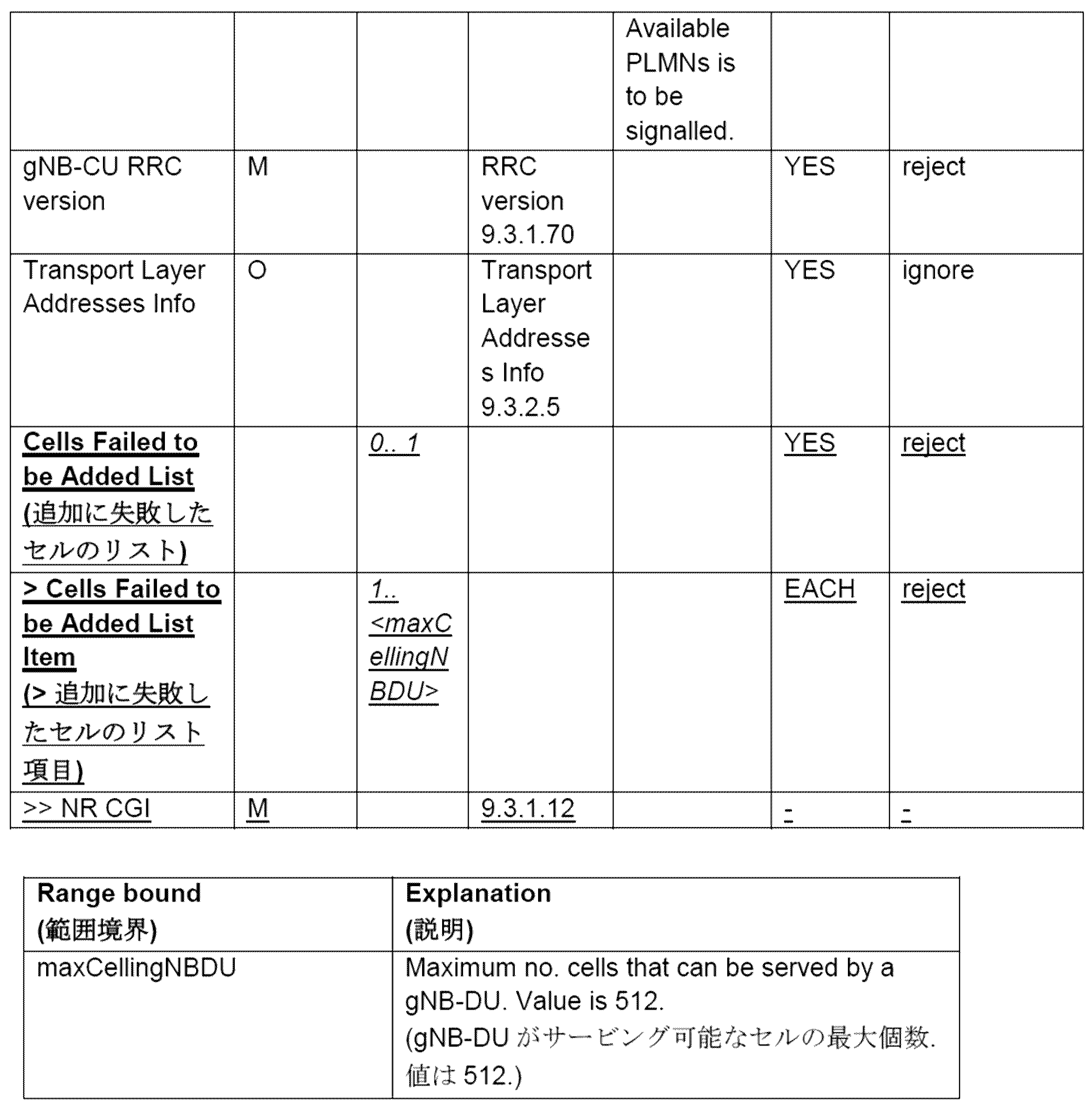
This message is sent by the gNB-CU to transfer information associated with the F1-C interface instance.
Direction: gNB-CU → gNB-DU
別の例では、gNB-DU設定更新手順中に、gNB-DUは、GNB-DU CONFIGURATION UPDATE(GNB-DU設定更新)メッセージをgNB-CUへ送信し、当該メッセージにおいて、ある数のセルが作成されることが要求される。これは、基地局DUによってサービングされるべき第1の複数のセルについての情報を記憶することを求める、基地局DUからの要求の一例でありうる。gNB-CUは、セル数が、サポートされるセルの最大個数を超え、その結果として、Cells Failed to be Added List IEを含むGNB-DU CONFIGURATION UPDATE ACKNOWLEDGE(GNB-DU設定更新確認応答)メッセージで応答することを実現する。これは、セルのgNB-CU総限界を超えたことに起因するもの、又は単一のDUに対して許容されるセルの限界を超えたことに起因するものの両方がありうる。これは、第1の複数のセルについての情報を記憶すると、基地局CUが記憶できるセルの最大個数を超えることになることを示す応答の一例でありうる。gNB-DUは、新しいIEを有するGNB-DU CONFIGURATION UPDATE ACKNOWLEDGEメッセージを受信すると、追加に失敗したセルは、gNB-CUにおいてアクティブ化されるために利用可能でないことを理解しなければならない。gNB-DUは、後の段階で、アクティブ化されるべき新たなセルのリスト及び非アクティブ化されるべきセルのリストを示す、gNB-DU Configuration Update(gNB-DU設定更新)メッセージを、gNB-CUへシグナリングすることを決定してもよく、即ち、gNB-DUは、gNB-CUによってアクティブ化される準備が整ったセルの全体のリストを調整することできる。 In another example, during a gNB-DU configuration update procedure, the gNB-DU sends a GNB-DU CONFIGURATION UPDATE message to the gNB-CU, in which a certain number of cells required to be done. This may be an example of a request from the base station DU to store information about the first plurality of cells to be served by the base station DU. The gNB-CU responds with a GNB-DU CONFIGURATION UPDATE ACKNOWLEDGE message containing the Cells Failed to be Added List IE if the number of cells exceeds the maximum number of cells supported. Realize what you want to do. This can be both due to exceeding the cell's gNB-CU total limit, or due to exceeding the allowed cell limit for a single DU. This may be an example of a response indicating that storing information about the first plurality of cells would exceed the maximum number of cells that the base station CU can store. When the gNB-DU receives the GNB-DU CONFIGURATION UPDATE ACKNOWLEDGE message with a new IE, it must understand that the cells that failed to be added are not available to be activated in the gNB-CU. At a later stage, the gNB-DU sends a gNB-DU Configuration Update message indicating the list of new cells to be activated and the list of cells to be deactivated. It may decide to signal to the CU, ie the gNB-DU can adjust the entire list of cells ready to be activated by the gNB-CU.
一例において、GNB-DU CONFIGURATION ACKNOWLEDGEメッセージは以下のとおりでありうる: In one example, the GNB-DU CONFIGURATION ACKNOWLEDGE message may be as follows:
9.2.1.8 GNB-DU CONFIGURATION UPDATE ACKNOWLEDGE
このメッセージは、F1-Cインタフェース・インスタンスに関連付けられた情報の更新について確認応答を行うためにgNB-CUによって送信される。
注: F1-Cシグナリング・トランスポートが、いくつかのF1-Cインタフェース・インスタンス間で共有される場合、このメッセージは、いくつかのF1-Cインタフェース・インスタンスに関連付けられた更新済み情報を転送しうる。
方向: gNB-CU → gNB-DU
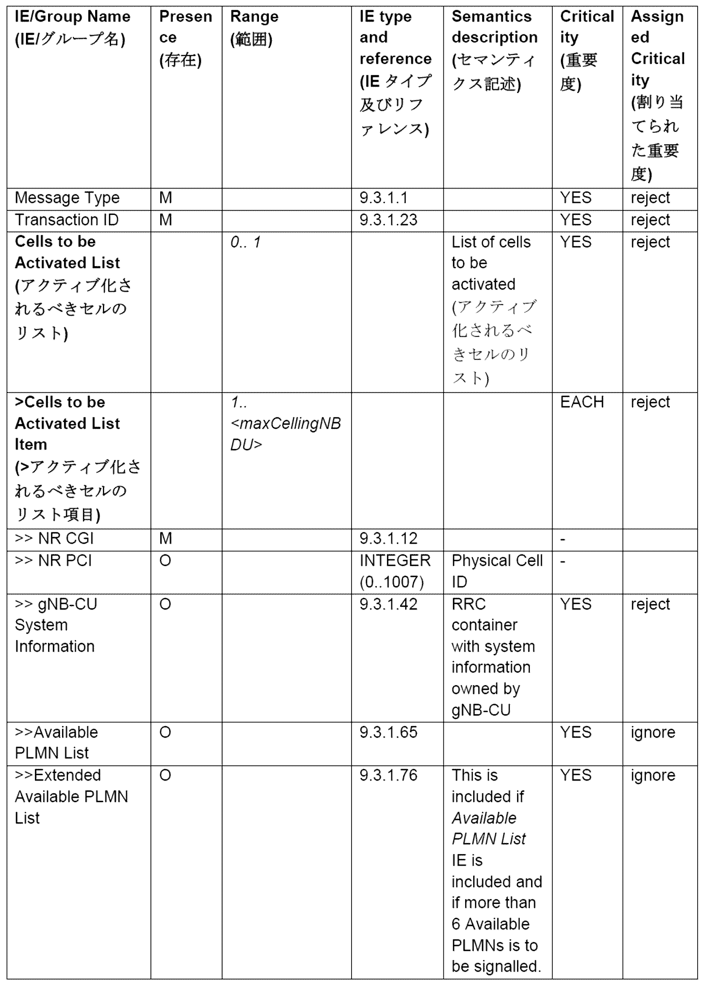
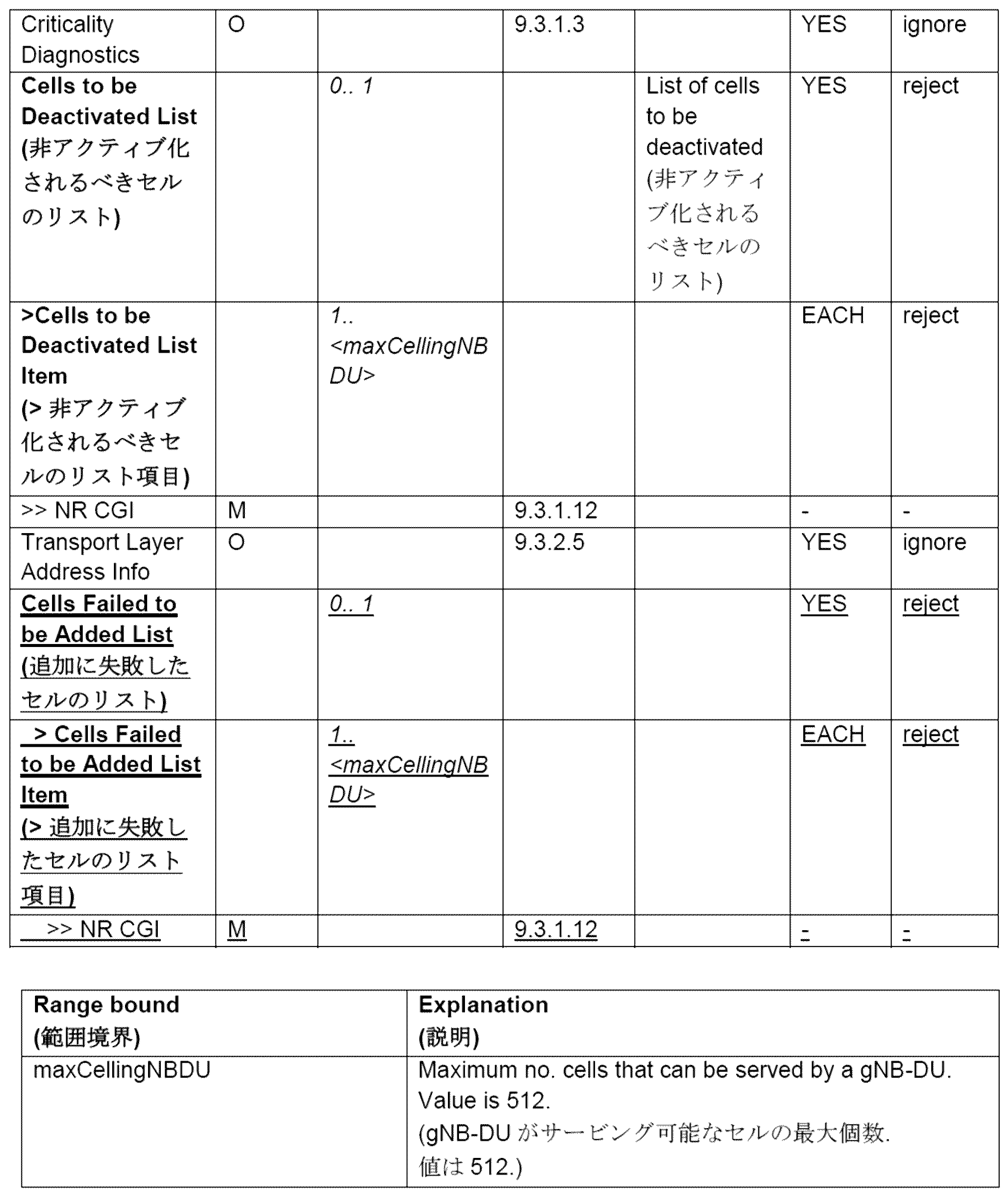
This message is sent by the gNB-CU to acknowledge the update of information associated with the F1-C interface instance.
Note: If the F1-C signaling transport is shared between several F1-C interface instances, this message may transfer updated information associated with several F1-C interface instances. sell.
Direction: gNB-CU → gNB-DU
いくつかの例では、本明細書で開示される実施形態のいずれかを用いて使用されうる新たな原因値(cause value)を導入することも提案され、例えば、F1Setup Responseメッセージ及びgNB-DU Configuration Update Acknowledgeメッセージに追加されうる。新たな原因値は、例えば、gNB-CU Cell Capacity Exceeded(gNB-CUセル容量超過)であってよく、セットアップを要求されたセルの個数が、gNB-CU内の最大セル容量を超えていたことを意味する。これは、いくつかの例において、以下の例のようにTS 38.473において定義可能である: In some examples, it is also proposed to introduce new cause values that can be used with any of the embodiments disclosed herein, for example in the F1Setup Response message and gNB-DU Configuration. Can be added to the Update Acknowledge message. The new cause value may be, for example, gNB-CU Cell Capacity Exceeded, where the number of cells requested to be set up exceeded the maximum cell capacity in the gNB-CU. means. This can be defined in TS 38.473 in some examples as in the following example:
9.3.1.2 Cause
Cause IE(原因IE)の目的は、F1APプロトコルのための特定のイベントの理由を示すことである。
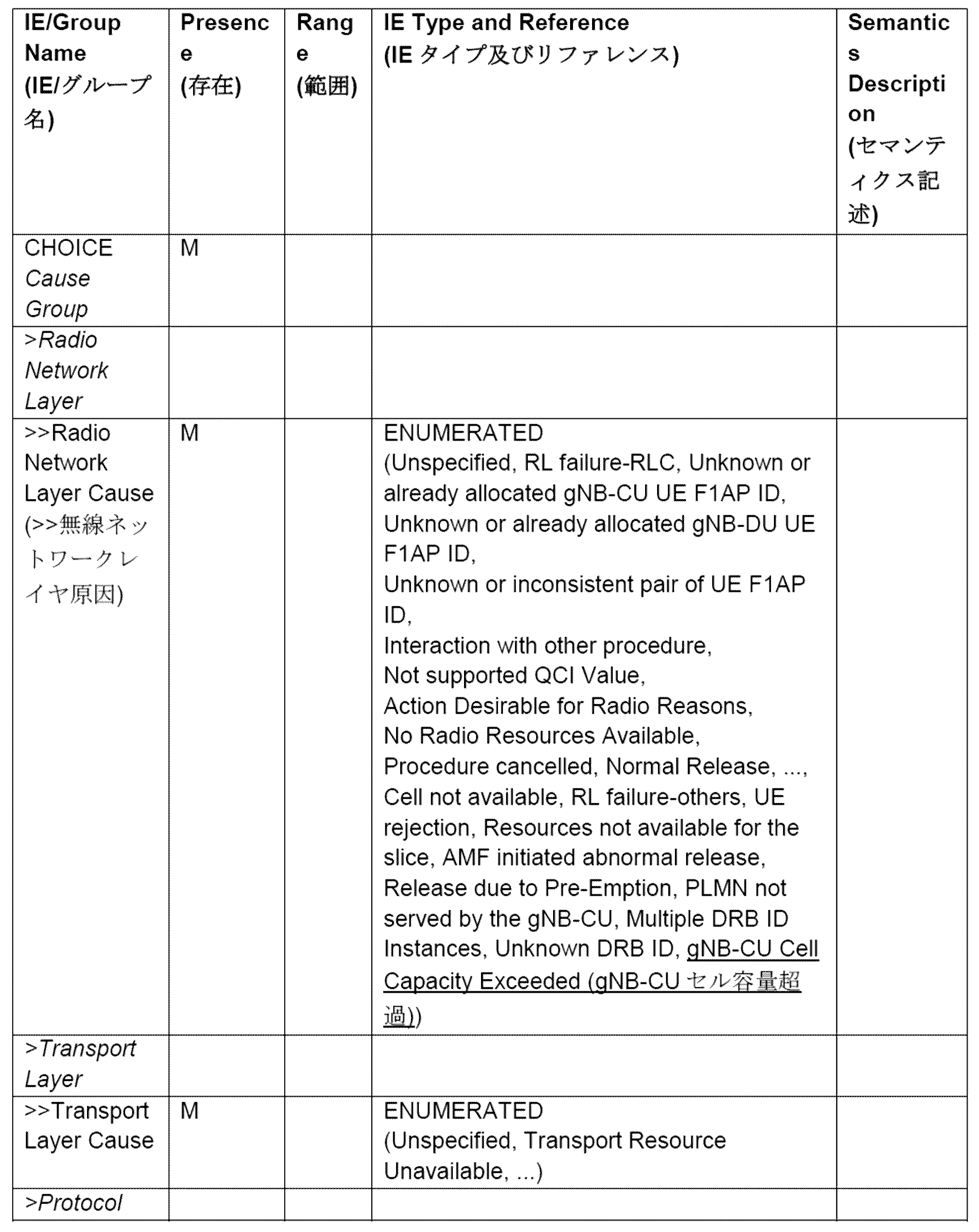
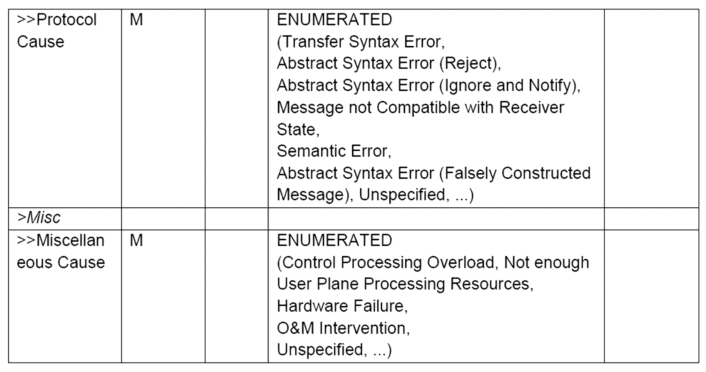
The purpose of the Cause IE is to indicate the reason for a particular event for the F1AP protocol.
種々の原因値の意味は以下の表に記載されている。一般に、「not supported(サポートされていない)」原因値は、関連する能力が欠如していることを示す。一方、「not available(利用可能ではない)」原因値は、関連する能力が存在するが、要求されたアクションを実行するために利用可能なリソースが不十分であったことを示す。


方法2:失敗理由のインジケーションを伴う手順失敗
特定の例では、F1セットアップ手順中に、gNB-DUは、F1 SETUP REQUEST(F1セットアップ要求)メッセージをgNB-CUへ送信し、当該メッセージにおいて、ある数のセルが作成されることが要求される。これは、基地局分散ユニット(DU)によってサービングされるべき第1の複数のセルについての情報を記憶することを求める、基地局DUからの要求の一例でありうる。gNB-CUは、セル数が、サポートされるセルの最大個数を超え、その結果として、Number of available cells IEを含むF1 SETUP FAILURE(F1セットアップ失敗)メッセージで応答することを実現する。これは、第1の複数のセルについての情報を記憶すると、基地局CUが記憶できるセルの最大個数を超えることになることを示す応答の一例でありうる。gNB-DUは、新しいIEを有するF1 SETUP FAILUREメッセージを受信すると、セットアップを要求されたセルの個数がgNB-CU限界を超えたと理解しなければならない。これは、セルのgNB-CU総限界を超えたことに起因するもの、又は単一のDUに対して許容されるセルの限界(即ち、maxCellingNBDU)を超えたことに起因するものの両方がありうる。現在の挙動には変更は無いので、失敗した手順では、gNB-CUに対して、又はgNB-CU内で変更された他の含められたデータに対して、セルは追加されない。
Method 2: Procedure failure with indication of failure reason In a specific example, during the F1 setup procedure, the gNB-DU sends an F1 SETUP REQUEST message to the gNB-CU, in which the A number of cells are required to be created. This may be an example of a request from a base station distribution unit (DU) to store information about a first plurality of cells to be served by the base station distribution unit (DU). The gNB-CU realizes that the number of cells exceeds the maximum number of supported cells and as a result responds with an F1 SETUP FAILURE message containing the Number of available cells IE. This may be an example of a response indicating that storing information about the first plurality of cells would exceed the maximum number of cells that the base station CU can store. Upon receiving the F1 SETUP FAILURE message with a new IE, the gNB-DU shall understand that the number of cells requested to be set up has exceeded the gNB-CU limit. This can be both due to exceeding the cell's gNB-CU total limit or due to exceeding the allowed cell limit for a single DU (i.e. maxCellingNBDU) . Since there is no change in the current behavior, the failed procedure will not add cells to the gNB-CU or to any other included data that has changed within the gNB-CU.
いくつかの例において、F1 SETUP FAILURE(F1セットアップ失敗)メッセージは以下のとおりでありうる: In some examples, the F1 SETUP FAILURE message can be:
9.2.1.6 F1 SETUP FAILURE
このメッセージは、F1セットアップの失敗を知らせるためにgNB-CUによって送信される。
方向: gNB-CU → gNB-DU

This message is sent by the gNB-CU to signal F1 setup failure.
Direction: gNB-CU → gNB-DU
別の例では、gNB-DU設定更新手順中に、gNB-DUは、GNB-DU CONFIGURATION UPDATE(GNB-DU設定更新)メッセージをgNB-CUへ送信し、当該メッセージにおいて、ある数のセルが作成されることが要求される。これは、基地局DUによってサービングされるべき第1の複数のセルについての情報を記憶することを求める、基地局分散ユニット(DU)からの要求の一例でありうる。gNB-CUは、セル数が、サポートされるセルの最大個数を超え、その結果として、Number of available cells IEを含むGNB-DU CONFIGURATION UPDATE FAILURE(GNB-DU設定更新失敗)メッセージで応答することを実現する。これは、第1の複数のセルについての情報を記憶すると、基地局CUが記憶できるセルの最大個数を超えることになることを示す応答の一例でありうる。gNB-DUは、新しいIEを有するGNB-DU CONFIGURATION UPDATE FAILUREメッセージを受信すると、セットアップを要求されたセルの個数がgNB-CU限界を超えたと理解しなければならない。これは、セルのgNB-CU総限界を超えたことに起因するもの、又は単一のDUに対して許容されるセルの限界(即ち、maxCellingNBDU)を超えたことに起因するものの両方がありうる。現在の挙動には変更は無いので、失敗した手順では、gNB-CUに対して、又はgNB-CU内で変更された他の含められたデータに対して、セルは追加されない。 In another example, during a gNB-DU configuration update procedure, the gNB-DU sends a GNB-DU CONFIGURATION UPDATE message to the gNB-CU, in which a certain number of cells required to be done. This may be an example of a request from a base station distribution unit (DU) to store information about the first plurality of cells to be served by the base station DU. The gNB-CU shall indicate that the number of cells exceeds the maximum number of cells supported and, as a result, responds with a GNB-DU CONFIGURATION UPDATE FAILURE message containing the Number of available cells IE. Realize. This may be an example of a response indicating that storing information about the first plurality of cells would exceed the maximum number of cells that the base station CU can store. When the gNB-DU receives a GNB-DU CONFIGURATION UPDATE FAILURE message with a new IE, it shall understand that the number of cells requested to be set up has exceeded the gNB-CU limit. This can be both due to exceeding the cell's gNB-CU total limit or due to exceeding the allowed cell limit for a single DU (i.e. maxCellingNBDU) . Since there is no change in the current behavior, the failed procedure will not add cells to the gNB-CU or to any other included data that has changed within the gNB-CU.
いくつかの例において、GNB-DU CONFIGURATION UPDATE FAILURE(GNB-DU設定更新失敗)メッセージは以下のとおりでありうる:
9.2.1.9 GNB-DU CONFIGURATION UPDATE FAILURE
このメッセージは、gNB-DU設定更新の失敗を知らせるためにgNB-CUによって送信される。
方向: gNB-CU → gNB-DU

9.2.1.9 GNB-DU CONFIGURATION UPDATE FAILURE
This message is sent by the gNB-CU to signal gNB-DU configuration update failure.
Direction: gNB-CU → gNB-DU
いくつかの例では、本開示の任意の実施形態で使用されうる新しい原因値を導入することも提案される。新たな原因値は、例えば、gNB-CU Cell Capacity Exceeded(gNB-CUセル容量超過)であってよく、セットアップを要求されたセルの個数が、gNB-CU内の最大セル容量を超えていたことを意味する。これは、いくつかの例では、TS 38.473において例えば以下のように定義可能である: In some examples, it is also proposed to introduce new cause values that may be used in any embodiment of this disclosure. The new cause value may be, for example, gNB-CU Cell Capacity Exceeded, where the number of cells requested to be set up exceeded the maximum cell capacity in the gNB-CU. means. This can, in some examples, be defined in TS 38.473 as, for example:
9.3.1.2 Cause
Cause IE(原因IE)の目的は、F1APプロトコルのための特定のイベントの理由を示すことである。


The purpose of the Cause IE is to indicate the reason for a particular event for the F1AP protocol.
種々の原因値の意味は以下の表に記載されている。一般に、「not supported(サポートされていない)」原因値は、関連する能力が欠如していることを示す。一方、「not available(利用可能ではない)」原因値は、関連する能力が存在するが、要求されたアクションを実行するために利用可能なリソースが不十分であったことを示す。


本明細書で説明される主題は任意の好適なコンポーネントを使用して任意の適切な種類のシステムで実装されうるが、本明細書で開示される実施形態は、図7に示される例示的な無線ネットワーク等の無線ネットワークに関連して説明される。簡単化のため、図7の無線ネットワークは、ネットワークQQ106、ネットワークノードQQ160及びQQ160b、並びにWD QQ110、QQ110b及びQQ110cのみを示す。実際には、無線ネットワークは、無線デバイス間の通信、又は無線デバイスと他の通信デバイス(例えば、固定電話、サービスプロバイダ、又は他の任意のネットワークノード又はエンドデバイス)との間の通信をサポートするのに適した任意の追加要素を更に含みうる。図示されたコンポーネントのうち、ネットワークノードQQ160及び無線デバイス(WD)QQ110が、更なる詳細とともに示されている。無線ネットワークは、無線デバイスによって提供されるサービス又は無線デバイスを介して提供されるサービスへの無線デバイスのアクセス及び/又は当該サービスの使用を容易にするために、通信及び他のタイプのサービスを1つ以上の無線デバイスに提供しうる。 Although the subject matter described herein may be implemented in any suitable type of system using any suitable components, embodiments disclosed herein may be implemented using the exemplary system shown in FIG. Description will be made in the context of wireless networks, such as wireless networks. For simplicity, the wireless network of FIG. 7 only shows network QQ 106, network nodes QQ 160 and QQ 160b, and WDs QQ 110, QQ 110b and QQ 110c. In practice, a wireless network supports communication between wireless devices or between wireless devices and other communication devices (e.g., landline telephones, service providers, or any other network nodes or end devices). It may further include any additional elements suitable for. Of the illustrated components, network node QQ 160 and wireless device (WD) QQ 110 are shown with additional details. A wireless network integrates communications and other types of services to facilitate a wireless device's access to and/or use of services provided by or through the wireless device. may be provided to more than one wireless device.
無線ネットワークは、任意のタイプの通信、遠隔通信、データ、セルラ、及び/又は無線ネットワーク又は他の同様のタイプのシステムを備えうる、及び/又はそれらとのインタフェースを行いうる。いくつかの実施形態では、無線ネットワークは、特定の規格又は他のタイプの予め定められた規則又は手順に従って動作するように構成されうる。このため、無線ネットワークの特定の実施形態は、Global System for Mobile Communications(GSM(登録商標))、Universal Mobile Telecommunications System(UMTS)、Long Term Evolution(LTE)、及び/又は他の適切な2G、3G、4G若しくは5G規格等の通信規格と、IEEE 802.11規格等の無線ローカルエリアネットワーク(WLAN)規格と、Worldwide Interoperability for Microwave Access(WiMax)、Bluetooth(登録商標)、Z‐Wave及び/又はZigBee(登録商標)規格等の、任意の他の適切な無線通信規格と、の少なくとも1つを実装しうる。 A wireless network may comprise and/or interface with any type of communications, telecommunications, data, cellular, and/or wireless network or other similar type system. In some embodiments, a wireless network may be configured to operate according to a particular standard or other type of predetermined rules or procedures. To this end, certain embodiments of wireless networks may include Global System for Mobile Communications (GSM), Universal Mobile Telecommunications System (UMTS), Long Term Evolution (LTE), and/or other suitable 2G, 3G , 4G or 5G standards; wireless local area network (WLAN) standards such as the IEEE 802.11 standard; and Worldwide Interoperability for Microwave Access (WiMax), Bluetooth®, Z-Wave and/or ZigBee. and any other suitable wireless communication standards, such as the TM Standard.
ネットワークQQ106は、1つ以上のバックホールネットワーク、コアネットワーク、IPネットワーク、公衆交換電話網(PSTN)、パケットデータネットワーク、光ネットワーク、ワイドエリアネットワーク(WAN)、ローカルエリアネットワーク(LAN)、無線ローカルエリアネットワーク(WLAN)、有線ネットワーク、無線ネットワーク、メトロポリタンエリアネットワーク、及びデバイス間の通信を可能にする他のネットワーク、を含みうる。 Network QQ 106 may include one or more backhaul networks, core networks, IP networks, public switched telephone networks (PSTNs), packet data networks, optical networks, wide area networks (WANs), local area networks (LANs), wireless local area network (WLAN), wired networks, wireless networks, metropolitan area networks, and other networks that enable communication between devices.
ネットワークノードQQ160及びWD QQ110は、以下でより詳細に説明する様々なコンポーネントを備える。これらのコンポーネントは、無線ネットワークで無線コネクションを提供する等の、ネットワークノード及び/又は無線デバイスの機能を提供するために連携する。種々の実施形態において、無線ネットワークは、任意の数の有線又は無線ネットワークと、ネットワークノードと、基地局と、コントローラと、無線デバイスと、中継局と、有線又は無線コネクションを介するかどうかによらずデータ及び/又は信号の通信を容易にしうる又は当該通信に参加しうる任意の他のコンポーネント又はシステムとのうちの少なくとも1つを備えうる。 Network node QQ 160 and WD QQ 110 include various components described in more detail below. These components work together to provide network node and/or wireless device functionality, such as providing wireless connections in a wireless network. In various embodiments, a wireless network may include any number of wired or wireless networks, network nodes, base stations, controllers, wireless devices, relay stations, whether through wired or wireless connections. and/or any other components or systems that may facilitate or participate in communications of data and/or signals.
本明細書で使用されるように、ネットワークノードは、無線デバイスへの無線アクセスを可能にする及び/又は提供するため、及び/又は、無線ネットワーク内の他の機能(例えば、管理)を実行するために、無線デバイスと直接又は間接の通信、及び/又は無線ネットワーク内の他のネットワークノード又は装置との通信を、行うことができる装置、行うように構成された装置、及び/又は行うように動作可能な装置を指す。ネットワークノードの例には、アクセスポイント(AP)(例えば、無線アクセスポイント)、基地局(BS)(例えば、無線基地局、ノードB、進化型ノードB(eNB)及びNRノードB(gNB))が含まれるが、これらに限定されない。基地局は、それらが提供するカバレッジの量(又は別の言い方をすれば、それらの送信電力レベル)に基づいて分類される場合があり、その場合、フェムト基地局、ピコ基地局、マイクロ基地局、又はマクロ基地局とも称されうる。基地局は、リレーを制御するリレーノード又はリレードナーノードであってもよい。ネットワークノードは更に、集中型デジタルユニット及び/又はリモート無線ユニット(RRU)(リモート無線ヘッド(RRH)と称される場合がある)等の、分散型無線基地局の1つ以上の(又は全ての)部分を含みうる。このようなリモート無線ユニットは、アンテナ一体型無線機としてアンテナと一体化される場合とされない場合がある。分散型無線基地局の一部は、分散アンテナシステム(DAS)におけるノードとも称されることがある。ネットワークノードの更に別の例には、MSR BR等のマルチスタンダード無線(MSR)機器、無線ネットワークコントローラ(RNC)又は基地局コントローラ(BSC)等のネットワークコントローラ、基地トランシーバ局(BTS)、送信ポイント、送信ノード、マルチセル/マルチキャスト調整エンティティ(MCE)、コアネットワークノード(例えば、MSC、MME)、O&Mノード、OSSノード、SONノード、測位ノード(例えば、E-SMLC)、及び/又はMDTが含まれる。別の例として、ネットワークノードは、以下においてより詳細に説明されるように、仮想ネットワークノードであってもよい。しかしながら、より一般的には、ネットワークノードは、無線ネットワークへのアクセスを有する無線デバイスを実現及び/又は提供するように、又は、無線ネットワークにアクセスした無線デバイスに何らかのサービスを提供するように、能力を有する、構成された、配置された、及び/又は動作可能な、任意の適切なデバイス(又はデバイス群)を表しうる。 As used herein, a network node enables and/or provides wireless access to wireless devices and/or performs other functions (e.g., management) within a wireless network. Apparatus capable of, configured to, and/or configured to communicate directly or indirectly with a wireless device and/or with other network nodes or devices within a wireless network in order to Refers to an operational device. Examples of network nodes include access points (APs) (e.g., wireless access points), base stations (BS) (e.g., wireless base stations, Node Bs, evolved Node Bs (eNBs), and NR Node Bs (gNBs)). including, but not limited to. Base stations may be classified based on the amount of coverage they provide (or, put another way, their transmit power level), in which case they are classified into femto base stations, pico base stations, and micro base stations. , or a macro base station. A base station may be a relay node or a relay donor node that controls a relay. A network node may further include one or more (or all) of a distributed radio base station, such as a centralized digital unit and/or a remote radio unit (RRU) (sometimes referred to as a remote radio head (RRH)). ) may be included. Such a remote radio unit may or may not be integrated with an antenna as an integrated antenna radio. Some distributed radio base stations may also be referred to as nodes in a distributed antenna system (DAS). Further examples of network nodes include multi-standard radio (MSR) equipment such as MSR BRs, network controllers such as radio network controllers (RNCs) or base station controllers (BSCs), base transceiver stations (BTSs), transmission points, Included are a transmitting node, a multicell/multicast coordination entity (MCE), a core network node (eg, MSC, MME), an O&M node, an OSS node, a SON node, a positioning node (eg, E-SMLC), and/or an MDT. As another example, the network node may be a virtual network node, as described in more detail below. However, more generally, a network node has the ability to enable and/or provide wireless devices with access to a wireless network, or to provide some service to wireless devices that have access to a wireless network. may represent any suitable device (or devices) having, configured, arranged, and/or operable.
図7では、ネットワークノードQQ160は、処理回路QQ170、デバイス読取可能媒体QQ180、インタフェースQQ190、補助装置QQ184、電源QQ186、電力回路QQ187、及びアンテナQQ162を備える。図7の例示的な無線ネットワークに示されたネットワークノードQQ160は、ハードウェアコンポーネントの図示された組み合わせを含むデバイスを表しうるが、他の実施形態は、異なるコンポーネントの組み合わせを有するネットワークノードを含みうる。ネットワークノードは、本明細書で開示されるタスク、特徴、機能、及び方法を実行するために必要とされるハードウェア及び/又はソフトウェアの任意の適切な組み合わせを備えることを理解されたい。更に、ネットワークノードQQ160のコンポーネントは、より大きなボックス内に配置された単一のボックスとして示されているか、又は複数のボックス内にネストされているが、実際には、ネットワークノードは、単一の図示されたコンポーネントを構成する複数の異なる物理的なコンポーネントを備えうる(例えば、デバイス読取可能媒体QQ180は、複数の別個のハードドライブと複数のRAMモジュールを備えうる)。 In FIG. 7, network node QQ160 includes processing circuitry QQ170, device readable medium QQ180, interface QQ190, auxiliary equipment QQ184, power supply QQ186, power circuitry QQ187, and antenna QQ162. Although the network node QQ 160 shown in the example wireless network of FIG. 7 may represent a device that includes the illustrated combination of hardware components, other embodiments may include network nodes that have different combinations of components. . It is to be understood that a network node comprises any suitable combination of hardware and/or software required to perform the tasks, features, functions, and methods disclosed herein. Further, although the components of network node QQ 160 are shown as a single box located within a larger box or nested within multiple boxes, in reality, the network node The illustrated components may include multiple different physical components (eg, device-readable medium QQ 180 may include multiple separate hard drives and multiple RAM modules).
同様に、ネットワークノードQQ160は、複数の物理的に別個のコンポーネント(例えば、ノードBコンポーネント及びRNCコンポーネント、又はBTSコンポーネント及びBSCコンポーネント等)で構成されてもよく、それらはそれぞれ、独自のそれぞれのコンポーネントを有してもよい。ネットワークノードQQ160が複数の別個のコンポーネント(例えば、BTS及びBSCコンポーネント)を備える特定のシナリオでは、別個のコンポーネントのうちの1つ以上がいくつかのネットワークノード間で共有されうる。例えば、単一のRNCが複数のノードBを制御してもよい。このようなシナリオでは、固有のノードBとRNCとの各ペアが、単一の個別のネットワークノードと見なされる場合がある。いくつかの実施形態では、ネットワークノードQQ160は、複数の無線アクセス技術(RAT)をサポートするように構成されうる。そのような実施形態では、いくつかのコンポーネントが重複していてもよく(例えば、異なるRATのための別個のデバイス読取可能媒体QQ180)、いくつかのコンポーネントは再使用されてもよい(例えば、同じアンテナQQ162が複数のRATによって共有されてもよい)。また、ネットワークノードQQ160は、例えば、GSM、WCDMA(登録商標)、LTE、NR、WiFi又はBluetooth無線技術のような、ネットワークノードQQ160に統合される異なる複数の無線技術のための様々な例示されたコンポーネントの複数のセットを含みうる。これらの無線技術は、ネットワークノードQQ160内の同一の又は異なるチップ又はチップのセット及び他のコンポーネントに統合されうる。 Similarly, network node QQ 160 may be comprised of multiple physically distinct components (e.g., Node B and RNC components, or BTS and BSC components, etc.), each of which has its own respective component. It may have. In certain scenarios where network node QQ 160 comprises multiple separate components (eg, BTS and BSC components), one or more of the separate components may be shared among several network nodes. For example, a single RNC may control multiple Node Bs. In such a scenario, each unique Node B and RNC pair may be considered a single, separate network node. In some embodiments, network node QQ 160 may be configured to support multiple radio access technologies (RATs). In such embodiments, some components may be duplicated (e.g., separate device-readable media QQ180 for different RATs) and some components may be reused (e.g., the same Antenna QQ 162 may be shared by multiple RATs). The network node QQ 160 also has various instantiations for different wireless technologies integrated into the network node QQ 160, such as GSM, WCDMA, LTE, NR, WiFi or Bluetooth wireless technologies. May contain multiple sets of components. These wireless technologies may be integrated into the same or different chips or sets of chips and other components within network node QQ 160.
処理回路QQ170は、ネットワークノードによって提供されるものとして本明細書で説明される任意の判定、計算、又は類似の動作(例えば、ある取得動作)を実行するように構成される。処理回路QQ170によって実行されるこれらの動作は、例えば、取得された情報を他の情報に変換すること、取得された情報又は変換された情報を、ネットワークノードに格納された情報と比較すること、及び/又は取得された情報又は変換された情報に基づいて1つ以上の動作を実行すること、及び上記の処理の結果として判定を行うことによって、処理回路QQ170によって取得された情報を処理することを含みうる。 Processing circuitry QQ170 is configured to perform any determination, calculation, or similar operation described herein as provided by a network node (eg, certain acquisition operations). These operations performed by the processing circuit QQ170 include, for example, converting the obtained information into other information, comparing the obtained or converted information with information stored in the network node, and/or processing the information obtained by processing circuitry QQ170 by performing one or more operations based on the obtained or transformed information and making determinations as a result of said processing. may include.
処理回路QQ170は、マイクロプロセッサ、コントローラ、マイクロコントローラ、中央演算処理装置、デジタルシグナルプロセッサ、特定用途向け集積回路、フィールドプログラマブルゲートアレイ、又は任意の他の適切なコンピューティングデバイス、リソース、又はハードウェア、ソフトウェア及び/又は符号化ロジックの組み合わせ、のうちの1つ以上の組み合わせを備えてよく、これらは、単独で提供、又はデバイス読取可能媒体QQ180、ネットワークノードQQ160の機能等の、他のネットワークノードQQ160コンポーネントと併用して提供するように動作可能である。例えば、処理回路QQ170は、デバイス読取可能媒体QQ180又は処理回路QQ170内のメモリに格納された命令を実行しうる。そのような機能は、本明細書で説明される様々な無線フィーチャ、機能、又は利益のいずれかを提供することを含みうる。一部の実施形態において、処理回路QQ170は、システムオンチップ(SOC)上のシステムを含みうる。 The processing circuit QQ170 may include a microprocessor, controller, microcontroller, central processing unit, digital signal processor, application specific integrated circuit, field programmable gate array, or any other suitable computing device, resource, or hardware; A combination of software and/or encoding logic, provided alone or with other network nodes QQ 160, such as a device readable medium QQ 180, the functionality of network node QQ 160. Operable to provide in conjunction with components. For example, processing circuitry QQ170 may execute instructions stored on device-readable medium QQ180 or memory within processing circuitry QQ170. Such functionality may include providing any of the various wireless features, functions, or benefits described herein. In some embodiments, processing circuitry QQ170 may include a system on a system on a chip (SOC).
いくつかの実施形態では、処理回路QQ170は、無線周波数(RF)トランシーバ回路QQ172及びベースバンド処理回路QQ174のうちの1つ以上を含みうる。いくつかの実施形態では、無線周波数(RF)トランシーバ回路QQ172及びベースバンド処理回路QQ174は、別個のチップ(又はチップのセット)、ボード、又は無線ユニット及びデジタルユニット等のユニット上にあってもよい。代替の実施形態では、RFトランシーバ回路QQ172及びベースバンド処理回路QQ174の一部又は全部が、同じチップ又はチップのセット、ボード、又はユニット上にあってもよい。 In some embodiments, processing circuitry QQ170 may include one or more of radio frequency (RF) transceiver circuitry QQ172 and baseband processing circuitry QQ174. In some embodiments, radio frequency (RF) transceiver circuitry QQ172 and baseband processing circuitry QQ174 may be on separate chips (or sets of chips), boards, or units, such as a radio unit and a digital unit. . In alternative embodiments, some or all of the RF transceiver circuitry QQ172 and the baseband processing circuitry QQ174 may be on the same chip or set of chips, board, or unit.
特定の実施形態では、ネットワークノード、基地局、eNB、又はその他のネットワークデバイスによって提供されるものとして説明される機能の一部又は全部は、デバイス読取可能媒体QQ180上に格納されている又は処理回路QQ170内のメモリに格納されている命令が処理回路QQ170によって実行されることによって実行されうる。代替の実施形態では、当該機能の一部又は全部は、ハードワイヤード方式等で、別個の又は個別のデバイス読取可能媒体上に格納された命令を実行することなく、処理回路QQ170によって提供されうる。これらの実施形態のいずれにおいても、デバイス読取可能記憶媒体上に格納された命令を実行するか否かにかかわらず、処理回路QQ170は、説明される機能を実行するように構成されうる。そのような機能によって提供される利点は、処理回路QQ170のみ、又はネットワークノードQQ160の他のコンポーネントに限定されず、ネットワークノードQQ160全体によって、及び/又はエンドユーザ及び無線ネットワーク全体によって享受される。 In certain embodiments, some or all of the functionality described as being provided by a network node, base station, eNB, or other network device is stored on a device-readable medium QQ180 or processing circuitry. Instructions stored in memory within QQ 170 may be executed by execution by processing circuit QQ 170. In alternative embodiments, some or all of the functionality may be provided by processing circuitry QQ170 without executing instructions stored on a separate or separate device-readable medium, such as in a hard-wired manner. In any of these embodiments, processing circuitry QQ170 may be configured to perform the functions described, whether or not executing instructions stored on a device-readable storage medium. The benefits provided by such functionality are not limited to processing circuitry QQ170 alone or other components of network node QQ160, but are enjoyed by network node QQ160 as a whole and/or by end users and the wireless network as a whole.
デバイス読取可能媒体QQ180は、限定されることなく、永続的ストレージ、ソリッドステートメモリ、リモートマウントメモリ、磁気媒体、光学媒体、ランダムアクセスメモリ、読み出し専用メモリ、大容量記憶媒体(例えば、ハードディスク)、リムーバブル記憶媒体(例えば、フラッシュドライブ、コンパクトディスク(CD)又はデジタルビデオディスク(DVD))、及び/又は処理回路QQ170によって使用されうる情報、データ及び/又は命令を格納するその他の揮発性又は不揮発性、非一時的なデバイス読取可能及び/又はコンピュータ実行可能メモリデバイスを含む、任意の形態の揮発性又は不揮発性コンピュータ読取可能メモリを含みうる。デバイス読取可能媒体QQ180は、処理回路QQ170によって実行され、ネットワークノードQQ160によって利用されることが可能な、コンピュータプログラムと、ソフトウェアと、ロジック、ルール、コード、テーブル等のうちの1つ以上を含むアプリケーションと、他の命令との少なくとも1つを含む、任意の適切な命令、データ、又は情報を格納しうる。デバイス可読媒体QQ180は、処理回路QQ170によって行われた任意の演算値、及び/又はインタフェースQQ190を介して受信された任意のデータを格納するために使用されうる。いくつかの実施形態では、処理回路QQ170及びデバイス読取可能媒体QQ180が一体化されていると見なされる場合がある。 Device readable media QQ180 may include, without limitation, persistent storage, solid state memory, remotely mounted memory, magnetic media, optical media, random access memory, read only memory, mass storage media (e.g., hard disks), removable a storage medium (e.g., a flash drive, a compact disc (CD) or a digital video disc (DVD)), and/or other volatile or non-volatile storage medium that stores information, data and/or instructions that may be used by the processing circuitry QQ170; Any form of volatile or nonvolatile computer-readable memory may be included, including non-transitory device-readable and/or computer-executable memory devices. Device-readable medium QQ180 is an application that includes one or more of computer programs, software, logic, rules, code, tables, etc. that can be executed by processing circuitry QQ170 and utilized by network node QQ160. and other instructions. Device readable medium QQ180 may be used to store any operational values performed by processing circuitry QQ170 and/or any data received via interface QQ190. In some embodiments, processing circuitry QQ170 and device-readable medium QQ180 may be considered integrated.
インタフェースQQ190は、ネットワークノードQQ160、ネットワークQQ106、及び/又はWD QQ110間のシグナリング及び/又はデータの有線又は無線通信に使用される。図示されるように、インタフェースQQ190は、例えば有線コネクションを介してネットワークQQ106との間でデータを送受信するための(複数の)ポート/端子QQ194を備える。インタフェースQQ190は更に、アンテナQQ162に結合されうるか又は特定の実施形態ではその一部でありうる無線フロントエンド回路QQ192を含む。無線フロントエンド回路QQ192は、フィルタQQ198及び増幅器QQ196を備える。無線フロントエンド回路QQ192は、アンテナQQ162及び処理回路QQ170に接続されてもよい。無線フロントエンド回路は、アンテナQQ162と処理回路QQ170との間で通信される信号を調整するように構成されうる。無線フロントエンド回路QQ192は、無線コネクションを介して他のネットワークノード又はWDへ送出されるデジタルデータを受信しうる。無線フロントエンド回路QQ192は、フィルタQQ198及び/又は増幅器QQ196の組み合わせを用いて、デジタルデータを、適切なチャネル及び帯域幅パラメータを有する無線信号に変換しうる。その後、無線信号は、アンテナQQ162を介して送信されうる同様に、データを受信する場合、アンテナQQ162は、無線信号を収集し、当該無線信号は無線フロントエンド回路QQ192によってデジタルデータに変換される。デジタルデータは、処理回路QQ170に渡われる。他の実施形態では、インタフェースは、異なるコンポーネント及び/又はコンポーネントの異なる組み合わせを含みうる。 Interface QQ190 is used for wired or wireless communication of signaling and/or data between network node QQ160, network QQ106, and/or WD QQ110. As shown, interface QQ190 includes ports/terminals QQ194 for transmitting and receiving data to and from network QQ106, for example via a wired connection. Interface QQ190 further includes wireless front end circuitry QQ192, which may be coupled to or, in certain embodiments, part of, antenna QQ162. Wireless front end circuit QQ192 includes a filter QQ198 and an amplifier QQ196. Wireless front end circuitry QQ192 may be connected to antenna QQ162 and processing circuitry QQ170. Wireless front end circuitry may be configured to condition signals communicated between antenna QQ162 and processing circuitry QQ170. Wireless front end circuit QQ192 may receive digital data sent to other network nodes or WDs via wireless connections. Wireless front end circuitry QQ192 may use a combination of filters QQ198 and/or amplifiers QQ196 to convert the digital data to a wireless signal with appropriate channel and bandwidth parameters. Thereafter, the wireless signal may be transmitted via antenna QQ162. Similarly, when receiving data, antenna QQ162 collects the wireless signal, which is converted into digital data by wireless front end circuit QQ192. The digital data is passed to processing circuit QQ170. In other embodiments, the interface may include different components and/or different combinations of components.
特定の代替実施形態では、ネットワークノードQQ160は別個の無線フロントエンド回路QQ192を含んでいなくてもよく、その代わりに、処理回路QQ170が、無線フロントエンド回路を含み、別個の無線フロントエンド回路QQ192を伴わずにアンテナQQ162に接続されてもよい。同様に、いくつかの実施形態では、RFトランシーバ回路QQ172の全て又はいくつかは、インタフェースQQ190の一部とみなされうる。更に他の実施形態では、インタフェースQQ190は、無線ユニット(図示せず)の一部として、1つ以上のポート又は端子QQ194、無線フロントエンド回路QQ192、及びRFトランシーバ回路QQ172を含みうるとともに、インタフェースQQ190は、デジタルユニット(図示せず)の一部であるベースバンド処理回路QQ174と通信しうる。 In certain alternative embodiments, network node QQ160 may not include a separate wireless front-end circuit QQ192; instead, processing circuitry QQ170 includes wireless front-end circuitry and separate wireless front-end circuitry QQ192. It may also be connected to antenna QQ162 without. Similarly, in some embodiments, all or some of the RF transceiver circuits QQ172 may be considered part of the interface QQ190. In yet other embodiments, interface QQ190 may include one or more ports or terminals QQ194, wireless front-end circuitry QQ192, and RF transceiver circuitry QQ172 as part of a wireless unit (not shown); may be in communication with baseband processing circuitry QQ174, which is part of a digital unit (not shown).
アンテナQQ162は、無線信号を送信及び/又は受信するように構成された1つ以上のアンテナ又はアンテナアレイを含みうる。アンテナQQ162は、無線フロントエンド回路QQ190に結合されうるとともに、データ及び/又は信号を無線で送受信することが可能な任意のタイプのアンテナでありうる。いくつかの実施形態では、アンテナQQ162は、例えば2GHzと66GHzとの間で無線信号を送受信するように動作可能な、1つ以上の無指向性アンテナ、セクタアンテナ又はパネルアンテナを含んでもよい。無指向性アンテナは、任意の方向において無線信号を送受信するために使用されうる。セクタアンテナは、特定の領域内のデバイスからの無線信号を送受信するために使用されうる。パネルアンテナは、比較的直線状に無線信号を送受信するために使用される見通し内アンテナでありうる。いくつかの例では、2つ以上のアンテナの使用はMIMOと称されうる。いくつかの実施形態では、アンテナQQ162は、ネットワークノードQQ160とは別個であってもよく、インタフェース又はポートを介してネットワークノードQQ160に接続可能であってもよい。 Antenna QQ 162 may include one or more antennas or antenna arrays configured to transmit and/or receive wireless signals. Antenna QQ 162 may be coupled to wireless front end circuit QQ 190 and may be any type of antenna capable of wirelessly transmitting and receiving data and/or signals. In some embodiments, antenna QQ 162 may include one or more omnidirectional, sector, or panel antennas operable to transmit and receive wireless signals, for example, between 2 GHz and 66 GHz. Omnidirectional antennas can be used to transmit and receive wireless signals in any direction. Sector antennas may be used to transmit and receive wireless signals from devices within a particular area. A panel antenna can be a line-of-sight antenna used to transmit and receive wireless signals in a relatively straight line. In some examples, the use of two or more antennas may be referred to as MIMO. In some embodiments, antenna QQ 162 may be separate from network node QQ 160 and may be connectable to network node QQ 160 via an interface or port.
アンテナQQ162、インタフェースQQ190、及び/又は処理回路QQ170は、ネットワークノードによって実行されるものとして本明細書で説明される任意の受信動作及び/又は特定の取得動作を実行するように構成されうる。任意の情報、データ及び/又は信号は、無線デバイス、別のネットワークノード、及び/又は任意の他のネットワーク機器から受信されうる。同様に、アンテナQQ162、インタフェースQQ190、及び/又は処理回路QQ170は、ネットワークノードによって実行されるものとして本明細書で説明される任意の送信動作を実行するように構成されうる。任意の情報、データ及び/又は信号は、無線デバイス、別のネットワークノード、及び/又は任意の他のネットワーク機器へ送信されうる。 Antenna QQ162, interface QQ190, and/or processing circuitry QQ170 may be configured to perform any receiving operations and/or certain acquisition operations described herein as being performed by a network node. Any information, data and/or signals may be received from a wireless device, another network node, and/or any other network equipment. Similarly, antenna QQ162, interface QQ190, and/or processing circuitry QQ170 may be configured to perform any transmission operations described herein as being performed by a network node. Any information, data and/or signals may be transmitted to the wireless device, another network node, and/or any other network equipment.
電力回路QQ187は、電力管理回路を含みうるか又は電力管理回路に結合されうるとともに、本明細書に記載の機能を実行するための電力をネットワークノードQQ160のコンポーネントに供給するように構成される。電力回路QQ187は、電源QQ186から電力を受信しうる。電源QQ186及び/又は電力回路QQ187は、それぞれのコンポーネントに適した形式で(例えば、各コンポーネントに必要な電圧及び電流レベルで)ネットワークノードQQ160の様々なコンポーネントに電力を供給するように構成されうる。電源QQ186は、電力回路QQ187及び/又はネットワークノードQQ160に含まれてもよいし、又はその外部に設けられてもよい。例えば、ネットワークノードQQ160は、電気ケーブル等の入力回路又はインタフェースを介して、外部電源(例えば、電気コンセント)に接続可能であってもよく、それにより外部電源が電力回路QQ187に電力を供給する。更なる例として、電源QQ186は、電力回路QQ187に接続又は統合される、バッテリ又はバッテリパックの形態の電源を含みうる。外部電源に障害が発生した場合、バッテリがバックアップ電力を供給しうる。光起電デバイスのような他のタイプの電源も使用されうる。 Power circuitry QQ187 may include or be coupled to power management circuitry and is configured to provide power to components of network node QQ160 to perform the functions described herein. Power circuit QQ187 may receive power from power supply QQ186. Power supply QQ 186 and/or power circuit QQ 187 may be configured to power the various components of network node QQ 160 in a manner suitable for each component (eg, at voltage and current levels required for each component). Power supply QQ186 may be included in power circuit QQ187 and/or network node QQ160, or may be provided external thereto. For example, network node QQ160 may be connectable to an external power source (eg, an electrical outlet) via an input circuit or interface, such as an electrical cable, such that the external power source provides power to power circuit QQ187. As a further example, power source QQ 186 may include a power source in the form of a battery or battery pack connected to or integrated into power circuit QQ 187. In the event of a failure of the external power source, the battery may provide backup power. Other types of power sources such as photovoltaic devices may also be used.
ネットワークノードQQ160の代替的な実施形態は、本明細書に記載の機能のいずれか、及び/又は本明細書に記載の主題をサポートするために必要な任意の機能を含む、ネットワークノードの機能のある態様を提供することに関与しうる、図7に示されるもの以外の追加のコンポーネントを含みうる。例えば、ネットワークノードQQ160は、ネットワークノードQQ160への情報の入力を可能にし、かつ、ネットワークノードQQ160からの情報の出力を可能にするユーザインタフェース機器を含みうる。これにより、ユーザは、ネットワークノードQQ160の診断、保守、修理、及び他の管理機能を行いうる。 Alternative embodiments of network node QQ 160 may include any of the functionality described herein and/or any functionality necessary to support the subject matter described herein. Additional components beyond those shown in FIG. 7 may be included that may participate in providing certain aspects. For example, network node QQ 160 may include user interface equipment that allows information to be input to and output from network node QQ 160. This allows users to perform diagnosis, maintenance, repair, and other management functions of network node QQ 160.
本明細書で使用されるように、無線デバイス(WD)は、ネットワークノード及び/又は他の無線デバイスと無線で通信するように、能力を有する、構成された、配置された及び/又は動作可能なデバイスを指す。特に断りの無い限り、WDとの用語、本明細書ではユーザ装置(UE)と互換的に使用されうる。無線通信は、電磁波、電波、赤外線、及び/又は空気を介して情報を伝達するのに適した他のタイプの信号を使用して、無線信号を送信及び/又は受信することを伴いうる。いくつかの実施形態では、WDは、直接的なヒューマンインタラクションを伴わずに情報を送信及び/又は受信するように構成されうる。例えば、WDは、所定のスケジュールで、内部又は外部のイベントによってトリガされたとき、又はネットワークからの要求に応答して、ネットワークに情報を送信するように設計されてもよい。WDの例には、スマートフォン、携帯電話、voice over IP(VoIP)電話、無線ローカルループ電話、デスクトップコンピュータ、パーソナルデジタルアシスタント(PDA)、無線カメラ、ゲーム機又はデバイス、音楽ストレージ、再生装置、ウェアラブル端末デバイス、無線エンドポイント、移動局、タブレット、ラップトップ、laptop-embedded equipment(LEE)、laptop-mounted equipment(LME)、スマートデバイス、無線カスタマー構内設備(CPE:customer-premise equipment)、車載無線端末デバイス等が含まれるが、これらに限定されない。WDは、例えば、サイドリンク通信、vehicle-to-vehicle(V2V)、vehicle-to-infrastructure(V2I)、vehicle-to-everything(V2X)のための3GPP標準規格を実装することによって、device-to-device(D2D)通信をサポートすることがあり、この場合、D2D通信デバイスと称されることがある。更に別の具体例として、Internet of Things(IoT)シナリオでは、WDは、モニタリング及び/又は測定を実行し、そのようなモニタリング及び/又は測定の結果を別のWD及び/又はネットワークノードに送信するマシン又は他のデバイスを表しうる。この場合、WDは、3GPPコンテキストではMTCデバイスと称されうるmachine-to-machine(M2M)デバイスでありうる。1つの具体例として、WDは、3GPPのnarrow band(狭帯域)internet of things(NB-IoT)標準規格を実装するUEでありうる。そのようなマシン又はデバイスの具体例は、センサ、電力メータ等の計量デバイス、産業機械、又は家庭用若しくは個人用機器(例えば、冷蔵庫、テレビ等)、個人用ウェアラブル(例えば、時計、フィットネストラッカー等)である。他のシナリオでは、WDは、その動作状態、又はその動作に関連する他の機能を
モニタリング及び/又は報告することができる車両又は他の機器を表しうる。上述のようなWDは、無線コネクションのエンドポイントを表してもよく、その場合、デバイスは無線端末と称されうる。更に、上述のようなWDは、モバイルであってもよく、その場合、モバイルデバイス又はモバイル端末とも称されうる。
As used herein, a wireless device (WD) is capable of, configured, arranged and/or operable to wirelessly communicate with network nodes and/or other wireless devices. device. Unless otherwise specified, the term WD may be used interchangeably herein with user equipment (UE). Wireless communications may involve sending and/or receiving wireless signals using electromagnetic waves, radio waves, infrared radiation, and/or other types of signals suitable for conveying information over the air. In some embodiments, a WD may be configured to send and/or receive information without direct human interaction. For example, the WD may be designed to send information to the network on a predetermined schedule, when triggered by an internal or external event, or in response to a request from the network. Examples of WD include smartphones, mobile phones, voice over IP (VoIP) phones, wireless local loop phones, desktop computers, personal digital assistants (PDAs), wireless cameras, gaming consoles or devices, music storage, playback devices, wearables. device, wireless endpoint, mobile station, tablet, laptop, laptop-embedded equipment (LEE), laptop-mounted equipment (LME), smart device, wireless customer-premise equipment (CPE), vehicle-mounted wireless terminal device These include, but are not limited to. WD provides device-to- -device (D2D) communications, in which case it may be referred to as a D2D communications device. As yet another specific example, in an Internet of Things (IoT) scenario, a WD performs monitoring and/or measurements and sends the results of such monitoring and/or measurements to another WD and/or network node. May represent a machine or other device. In this case, the WD may be a machine-to-machine (M2M) device, which may be referred to as an MTC device in the 3GPP context. As one example, the WD may be a UE that implements the 3GPP narrow band internet of things (NB-IoT) standard. Examples of such machines or devices are sensors, metering devices such as power meters, industrial machinery, or household or personal appliances (e.g. refrigerators, televisions, etc.), personal wearables (e.g. watches, fitness trackers, etc.). ). In other scenarios, the WD may represent a vehicle or other equipment that can monitor and/or report its operating status or other functions related to its operation. A WD as described above may represent an endpoint of a wireless connection, in which case the device may be referred to as a wireless terminal. Furthermore, a WD as described above may be mobile, in which case it may also be referred to as a mobile device or mobile terminal.
図示されるように、無線デバイスQQ110は、アンテナQQ111、インタフェースQQ114、処理回路QQ120、デバイス読取可能媒体QQ130、ユーザインタフェース機器QQ132、補助装置QQ134、電源QQ136、及び電力回路QQ137を備える。WD QQ110は、例えば、例を挙げるだけでも、GSM、WCDMA、LTE、NR、WiFi、WiMAX、又はBluetooth無線技術等の、WD QQ110によってサポートされる異なる無線技術のために、図示されているコンポーネントのうちの1つ以上から成る複数のセットを含みうる。これらの無線技術は、WD QQ110内の他のコンポーネントと同一の又は異なるチップ又はチップセットに統合されうる。 As shown, wireless device QQ110 includes an antenna QQ111, an interface QQ114, processing circuitry QQ120, device readable media QQ130, user interface equipment QQ132, auxiliary equipment QQ134, a power supply QQ136, and power circuitry QQ137. The WD QQ110 includes components illustrated for different wireless technologies supported by the WD QQ110, such as GSM, WCDMA, LTE, NR, WiFi, WiMAX, or Bluetooth wireless technologies, to name but a few. may include multiple sets of one or more of the following: These wireless technologies may be integrated into the same or different chips or chipsets as other components within the WD QQ110.
アンテナQQ111は、無線信号を送信及び/又は受信するように構成された1つ以上のアンテナ又はアンテナアレイを含みうるとともに、インタフェースQQ114に接続される。特定の代替の実施形態では、アンテナQQ111は、WD QQ110とは別個であってもよく、インタフェース又はポートを介してWD QQ110に接続可能であってもよい。アンテナQQ111、インタフェースQQ114、及び/又は処理回路QQ120は、WDによって実行されるものとして本明細書で説明される任意の送信動作を実行するように構成されうる。任意の情報、データ、及び/又は信号は、ネットワークノード及び/又は別のWDから受信されうる。いくつかの実施形態では、無線フロントエンド回路及び/又はアンテナQQ111は、インタフェースとみなされうる。 Antenna QQ111 may include one or more antennas or antenna arrays configured to transmit and/or receive wireless signals and is connected to interface QQ114. In certain alternative embodiments, antenna QQ 111 may be separate from WD QQ 110 and may be connectable to WD QQ 110 via an interface or port. Antenna QQ111, interface QQ114, and/or processing circuitry QQ120 may be configured to perform any transmission operations described herein as being performed by a WD. Any information, data, and/or signals may be received from a network node and/or another WD. In some embodiments, the wireless front end circuit and/or antenna QQ111 may be considered an interface.
図示されるように、インタフェースQQ114は、無線フロントエンド回路QQ112及びアンテナQQ111を備える。無線フロントエンド回路QQ112は、1つ以上のフィルタQQ118及び増幅器QQ116を備える。無線フロントエンド回路QQ114は、アンテナQQ111及び処理回路QQ120に接続され、アンテナQQ111と処理回路QQ120との間で通信される信号を調整するように構成される。無線フロントエンド回路QQ112は、アンテナQQ111に結合されてもよいし、又はその一部であってもよい。いくつかの実施形態では、WD QQ110は別個の無線フロントエンド回路QQ112を含まなくてもよく、むしろ、処理回路QQ120が無線フロントエンド回路を含み、アンテナQQ111に接続されてもよい。同様に、いくつかの実施形態では、RFトランシーバ回路QQ122のいくつか又は全ては、インタフェースQQ114の一部とみなされうる。無線フロントエンド回路QQ112は、無線コネクションを介して他のネットワークノード又はWDに送出されるデジタルデータを受信しうる。無線フロントエンド回路QQ112は、フィルタQQ118及び/又は増幅器QQ116の組み合わせを用いて、デジタルデータを、適切なチャネル及び帯域幅パラメータを有する無線信号に変換しうる。その後、無線信号は、アンテナQQ111を介して送信されうる同様に、データを受信する場合、アンテナQQ111は、無線信号を収集し、当該無線信号は無線フロントエンド回路QQ112によってデジタルデータに変換される。デジタルデータは、処理回路QQ120に渡われる。他の実施形態では、インタフェースは、異なるコンポーネント及び/又はコンポーネントの異なる組み合わせを含みうる。 As shown, interface QQ114 includes a wireless front end circuit QQ112 and an antenna QQ111. Wireless front end circuit QQ112 includes one or more filters QQ118 and amplifiers QQ116. Wireless front end circuit QQ114 is connected to antenna QQ111 and processing circuit QQ120 and configured to condition signals communicated between antenna QQ111 and processing circuit QQ120. Wireless front end circuit QQ112 may be coupled to or part of antenna QQ111. In some embodiments, WD QQ110 may not include a separate wireless front end circuit QQ112; rather, processing circuit QQ120 may include wireless front end circuitry and be connected to antenna QQ111. Similarly, in some embodiments, some or all of the RF transceiver circuits QQ122 may be considered part of the interface QQ114. Wireless front end circuit QQ112 may receive digital data sent to other network nodes or WDs via wireless connections. Wireless front end circuit QQ112 may use a combination of filters QQ118 and/or amplifiers QQ116 to convert the digital data to a wireless signal with appropriate channel and bandwidth parameters. Thereafter, the wireless signal may be transmitted via antenna QQ111. Similarly, when receiving data, antenna QQ111 collects the wireless signal, which is converted into digital data by wireless front-end circuit QQ112. The digital data is passed to processing circuit QQ120. In other embodiments, the interface may include different components and/or different combinations of components.
処理回路QQ120は、マイクロプロセッサ、コントローラ、マイクロコントローラ、中央演算処理装置、デジタルシグナルプロセッサ、特定用途向け集積回路、フィールドプログラマブルゲートアレイ、又は任意の他の適切なコンピューティングデバイス、リソース、又はハードウェア、ソフトウェア及び/又は符号化ロジックの組み合わせ、のうちの1つ以上の組み合わせを備えてよく、これらは、単独で提供、又はデバイス読取可能媒体QQ130、WD QQ110の機能等の、他のWD QQ110コンポーネントと併用して提供するように動作可能である。そのような機能は、本明細書で説明される様々な無線フィーチャ、又は利益のいずれかを提供することを含みうる。例えば、処理回路QQ120は、本明細書で開示される機能を提供するために、デバイス読取可能媒体QQ130又は処理回路QQ120内のメモリに格納された命令を実行しうる。 The processing circuit QQ120 may include a microprocessor, controller, microcontroller, central processing unit, digital signal processor, application specific integrated circuit, field programmable gate array, or any other suitable computing device, resource, or hardware; A combination of software and/or encoding logic, provided alone or in conjunction with other WD QQ110 components, such as a device-readable medium QQ130, WD QQ110 functionality. Operable to provide in conjunction. Such functionality may include providing any of the various wireless features or benefits described herein. For example, processing circuitry QQ120 may execute instructions stored on device-readable medium QQ130 or memory within processing circuitry QQ120 to provide the functionality disclosed herein.
図示されるように、処理回路QQ120は、RFトランシーバ回路QQ122、ベースバンド処理回路QQ124、及びアプリケーション処理回路QQ126のうちの1つ以上を含む。他の実施形態では、処理回路は、異なるコンポーネント及び/又はコンポーネントの異なる組み合わせを含みうる。いくつかの実施形態では、WD QQ110の処理回路QQ120はSOCを備えうる。いくつかの実施形態では、RFトランシーバ回路QQ122、ベースバンド処理回路QQ124、及びアプリケーション処理回路QQ126は、別個のチップ又はチップセット上にあってもよい。代替の実施形態では、ベースバンド処理回路QQ124及びアプリケーション処理回路QQ126の一部又は全部は、1つのチップ又はチップセットに結合されてもよく、RFトランシーバ回路QQ122は別個のチップ又はチップセット上にあってもよい。更に代替の実施形態では、RFトランシーバ回路QQ122及びベースバンド処理回路QQ124の一部又は全部は、同一のチップ又はチップセット上にあってもよく、アプリケーション処理回路QQ126は、別個のチップ又はチップセット上にあってもよい。更に他の代替の実施形態では、RFトランシーバ回路QQ122、ベースバンド処理回路QQ124、及びアプリケーション処理回路QQ126の一部又は全部は、同一のチップ又はチップセットにおいて結合されてもよい。いくつかの実施形態では、RFトランシーバ回路QQ122は、インタフェースQQ114の一部であってもよい。RFトランシーバ回路QQ122は、処理回路QQ120のためにRF信号を調整しうる。 As shown, processing circuitry QQ120 includes one or more of RF transceiver circuitry QQ122, baseband processing circuitry QQ124, and application processing circuitry QQ126. In other embodiments, the processing circuitry may include different components and/or different combinations of components. In some embodiments, processing circuitry QQ120 of WD QQ110 may include an SOC. In some embodiments, RF transceiver circuitry QQ122, baseband processing circuitry QQ124, and application processing circuitry QQ126 may be on separate chips or chipsets. In alternative embodiments, some or all of baseband processing circuitry QQ124 and application processing circuitry QQ126 may be combined into one chip or chipset, and RF transceiver circuitry QQ122 may be on a separate chip or chipset. You can. In further alternative embodiments, some or all of RF transceiver circuitry QQ122 and baseband processing circuitry QQ124 may be on the same chip or chipset, and application processing circuitry QQ126 may be on a separate chip or chipset. It may be in In yet other alternative embodiments, some or all of RF transceiver circuitry QQ122, baseband processing circuitry QQ124, and application processing circuitry QQ126 may be combined in the same chip or chipset. In some embodiments, RF transceiver circuit QQ122 may be part of interface QQ114. RF transceiver circuit QQ122 may condition RF signals for processing circuit QQ120.
ある実施形態では、WDによって実行されるものとして本明細書に記載の機能の一部又は全部は、ある実施形態ではコンピュータ読取可能記憶媒体でありうるデバイス読取可能媒体QQ130上に格納された命令を実行する処理回路QQ120によって提供されうる。代替の実施形態では、当該機能の一部又は全部は、ハードワイヤード方式等で、別個の又は個別のデバイス読取可能記憶媒体上に格納された命令を実行することなく、処理回路QQ120によって提供されうる。これらの特定の実施形態のいずれにおいても、デバイス読取可能記憶媒体上に格納された命令を実行するか否かにかかわらず、処理回路QQ120は、説明される機能を実行するように構成されうる。そのような機能によって提供される利点は、処理回路QQ120のみ、又はWD QQ110の他のコンポーネントに限定されず、WD QQ110全体によって、及び/又はエンドユーザ及び無線ネットワーク全体によって享受される。 In some embodiments, some or all of the functions described herein as being performed by a WD may be performed using instructions stored on a device-readable medium QQ130, which in some embodiments may be a computer-readable storage medium. It may be provided by a processing circuit QQ120 that executes. In alternative embodiments, some or all of the functionality may be provided by processing circuitry QQ120 without executing instructions stored on a separate or separate device-readable storage medium, such as in a hard-wired manner. . In any of these particular embodiments, processing circuitry QQ120 may be configured to perform the functions described, whether or not executing instructions stored on a device-readable storage medium. The benefits provided by such functionality are not limited to only processing circuitry QQ120 or other components of WD QQ110, but are enjoyed by the entire WD QQ110 and/or by end users and wireless networks as a whole.
処理回路QQ120は、WDによって実行されるものとして本明細書に記載の任意の判定、計算、又は類似の動作(例えば、ある取得動作)を実行するように構成されうる。処理回路QQ120によって実行されるようなこれらの動作は、例えば、取得された情報を他の情報に変換すること、取得された情報又は変換された情報を、WD QQ110により格納された情報と比較すること、及び/又は取得された情報又は変換された情報に基づいて1つ以上の動作を実行すること、及び上記の処理の結果として判定を行うことによって、処理回路QQ120によって取得された情報を処理することを含みうる。 Processing circuitry QQ120 may be configured to perform any determinations, calculations, or similar operations described herein as being performed by a WD (eg, certain acquisition operations). These operations, as performed by the processing circuit QQ120, may include, for example, converting the acquired information into other information, comparing the acquired or transformed information with information stored by the WD QQ110. processing the information obtained by processing circuitry QQ120 by performing one or more operations based on the obtained or transformed information and/or making decisions as a result of the processing described above; may include doing.
デバイス読取可能媒体QQ130は、処理回路QQ120によって実行されることが可能な、コンピュータプログラムと、ソフトウェアと、ロジック、ルール、コード、テーブル等のうちの1つ以上を含むアプリケーションと、他の命令とのうちの少なくとも1つを格納するように動作可能でありうる。デバイス読取可能媒体QQ130は、コンピュータメモリ(例えば、ランダムアクセスメモリ(RAM)又は読み出し専用メモリ(ROM))、大容量記憶媒体(例えば、ハードディスク)、リムーバブル記憶媒体(例えば、コンパクトディスク(CD)又はデジタルビデオディスク(DVD))、及び/又は処理回路QQ120によって使用されうる情報、データ及び/又は命令を格納する任意の他の揮発性又は不揮発性、非一時的なデバイス読取可能及び/又はコンピュータ実行可能メモリデバイスを含みうる。いくつかの実施形態では、処理回路QQ120及びデバイス読取可能媒体QQ130が一体化されていると見なされる場合がある。 Device-readable medium QQ130 stores computer programs, software, applications including one or more of logic, rules, code, tables, etc., and other instructions that can be executed by processing circuitry QQ120. The storage device may be operable to store at least one of the storage devices. The device-readable medium QQ130 can include computer memory (e.g., random access memory (RAM) or read-only memory (ROM)), mass storage media (e.g., hard disk), removable storage media (e.g., compact disk (CD), or digital video disc (DVD)) and/or any other volatile or non-volatile, non-transitory device readable and/or computer-executable storing information, data and/or instructions that may be used by the processing circuitry QQ120. May include memory devices. In some embodiments, processing circuitry QQ120 and device-readable medium QQ130 may be considered integrated.
ユーザインタフェース機器QQ132は、人間のユーザがWD QQ110とインタラクションすることを可能にするコンポーネントを提供しうる。このようなインタラクションは、視覚的、聴覚的、触覚的等の多くの形態でありうる。ユーザインタフェース機器QQ132は、ユーザへの出力を生成するように、及びユーザがWD QQ110に入力を提供することを可能にするように動作可能でありうる。インタラクションのタイプは、WD QQ110に組み込まれたユーザインタフェース機器QQ132のタイプに応じて変わりうる。例えば、WD QQ110がスマートフォンである場合、インタラクションはタッチスクリーンを介するものでありうる。WD QQ110がスマートメーターである場合、インタラクションは使用量(例えば、使用されるガロン数)を提供する画面又は(例えば、煙が検知された場合に)音声アラートを提供するスピーカを介するものでありうる。ユーザインタフェース機器QQ132は、入力インタフェース、デバイス及び回路と、出力インタフェース、デバイス及び回路とを含みうる。ユーザインタフェース装置QQ132は、WD QQ110への情報の入力を可能にするように構成され、処理回路QQ120が入力情報を処理することを可能にするように処理回路QQ120に接続される。ユーザインタフェース機器QQ132は、例えば、マイクロフォン、近接センサ若しくは他のセンサ、キー/ボタン、タッチディスプレイ、1つ以上のカメラ、USBポート、又は他の入力回路を含みうる。ユーザインタフェース機器QQ132は更に、WD QQ110からの情報の出力を可能にし、処理回路QQ120がWD QQ110から情報を出力することを可能にするように構成される。ユーザインタフェース機器QQ132は、例えば、スピーカ、ディスプレイ、振動回路、USBポート、ヘッドホンインタフェース、又は他の出力回路を含みうる。ユーザインタフェース機器QQ132の1つ以上の入出力インタフェース、デバイス、及び回路を使用して、WD QQ110は、エンドユーザ及び/又は無線ネットワークと通信しうるとともに、本明細書に記載の機能からの利点をエンドユーザ及び/又は無線ネットワークが享受できるようにしうる。 User interface equipment QQ 132 may provide components that allow a human user to interact with WD QQ 110. Such interaction can be in many forms, such as visual, auditory, tactile, etc. User interface equipment QQ 132 may be operable to generate output to the user and to enable the user to provide input to WD QQ 110. The type of interaction may vary depending on the type of user interface equipment QQ132 incorporated into the WD QQ110. For example, if the WD QQ110 is a smartphone, the interaction may be via a touch screen. If the WD QQ110 is a smart meter, the interaction may be through a screen that provides usage (e.g., number of gallons used) or a speaker that provides an audio alert (e.g., if smoke is detected). . User interface equipment QQ132 may include input interfaces, devices and circuits, and output interfaces, devices and circuits. User interface device QQ132 is configured to enable input of information to WD QQ110 and is connected to processing circuitry QQ120 to enable processing circuitry QQ120 to process the input information. User interface equipment QQ132 may include, for example, a microphone, a proximity sensor or other sensor, keys/buttons, a touch display, one or more cameras, a USB port, or other input circuitry. User interface equipment QQ132 is further configured to enable output of information from WD QQ110 and to enable processing circuitry QQ120 to output information from WD QQ110. User interface equipment QQ132 may include, for example, a speaker, a display, a vibration circuit, a USB port, a headphone interface, or other output circuit. Using one or more input/output interfaces, devices, and circuits of user interface equipment QQ132, WD QQ110 may communicate with end users and/or wireless networks and benefit from the functionality described herein. It may be made available to end users and/or wireless networks.
補助装置QQ134は、一般にWDによって実行されない可能性があるより具体的な機能を提供するように動作可能である。これは、様々な目的のために測定を行うための専用センサ、有線通信等の追加のタイプの通信のためのインタフェースを含みうる。補助装置QQ134のコンポーネントを含むこと及び当該コンポーネントのタイプは、実施形態及び/又はシナリオに応じて変わりうる。 Auxiliary equipment QQ 134 is operable to provide more specific functions that may not generally be performed by the WD. This may include dedicated sensors to take measurements for various purposes, interfaces for additional types of communication, such as wired communication. The inclusion and type of components of auxiliary device QQ 134 may vary depending on the embodiment and/or scenario.
電源QQ136は、いくつかの実施形態ではバッテリ又はバッテリパックの形態でありうる。外部電源(例えば、電気コンセント)、光起電力デバイス、又はパワーセル等の、他のタイプの電源も使用されうる。WD QQ110は更に、電源QQ136からの電力を、電源QQ136からの電力を必要とするWD QQ110の種々の部分に送り、本明細書に記載される又は示される任意の機能を実行するための電力回路QQ137を含みうる。電力回路QQ137は、ある実施形態では電力管理回路を含みうる。電力回路QQ137は、追加的又は代替的には、外部電源から電力を受けるように動作可能であってもよく、その場合、WD QQ110は、入力回路又は電力ケーブル等のインタフェースを介して外部電源(電気コンセント等)に接続可能でありうる。ある実施形態において、電力回路QQ137は更に、外部電源から電源QQ136に電力を送るように動作可能であってもよい。これは、例えば電源QQ136の充電のためでありうる。電力回路QQ137は、電力が供給されるWD QQ110のそれぞれのコンポーネントに適した電力にするために、電源QQ136からの電力に対して任意の調整、変換、又は他の修正を行いうる。 Power supply QQ 136 may be in the form of a battery or battery pack in some embodiments. Other types of power sources may also be used, such as an external power source (eg, an electrical outlet), a photovoltaic device, or a power cell. WD QQ110 further includes power circuitry to route power from power supply QQ136 to various parts of WD QQ110 that require power from power supply QQ136 to perform any functions described or illustrated herein. QQ137 may be included. Power circuitry QQ137 may include power management circuitry in some embodiments. The power circuit QQ137 may additionally or alternatively be operable to receive power from an external power source, in which case the WD QQ110 receives power from the external power source (via an interface such as an input circuit or a power cable). electrical outlet, etc.). In some embodiments, power circuit QQ137 may be further operable to send power to power supply QQ136 from an external power source. This may be for example for charging the power supply QQ136. Power circuit QQ 137 may perform any adjustments, conversions, or other modifications to the power from power supply QQ 136 to make the power suitable for each component of WD QQ 110 being powered.
図8は、本明細書に記載の様々な態様に係るUEの一実施形態を示す。本明細書で使用されるように、ユーザ装置又はUEは、必ずしも、関連するデバイスの所有及び/又は操作を行う人間のユーザという意味でユーザを有するとは限らない。代わりに、UEは、人間のユーザへの販売又は人間のユーザによる操作が意図されているが、特定の人間のユーザ(例えば、スマートスプリンクラコントローラ)に関連付けられていなくてもよい、又は最初は関連付けられていなくてもよいデバイスを表しうる。あるいは、UEは、エンドユーザへの販売又はエンドユーザによる操作を意図されていないが、ユーザ(例えば、スマート電力メータ)に関連付けられうるか又は当該ユーザの利益のために操作されうるデバイスを表しうる。UE QQ200は、NB-IoT UE、マシンタイプ通信(MTC)UE、及び/又は拡張MTC(eMTC)UEを含む、第3世代パートナシッププロジェクト(3GPP)によって特定される任意のUEでありうる。図8に示されるように、UE QQ200は、3GPPのGSM、UMTS、LTE、及び/又は5G標準規格等の、第3世代パートナーシッププロジェクト(3GPP)によって公表された1つ以上の通信標準規格に従って通信するように設定されたWDの一例である。前述のように、WD及びUEとの用語は交換可能に使用されうる。したがって、図8はUEであるが、本明細書で説明されるコンポーネントはWDに等しく適用可能であり、その逆も同様である。 FIG. 8 illustrates one embodiment of a UE in accordance with various aspects described herein. As used herein, a user equipment or UE does not necessarily have a user in the sense of a human user who owns and/or operates the associated device. Alternatively, a UE may be intended for sale to or operation by a human user, but may not be associated with, or initially associated with, a particular human user (e.g., a smart sprinkler controller). can represent a device that does not have to be Alternatively, a UE may represent a device that is not intended for sale to or operation by an end user, but that may be associated with or operated for the benefit of a user (eg, a smart power meter). UE QQ200 may be any UE specified by the 3rd Generation Partnership Project (3GPP), including NB-IoT UEs, Machine Type Communication (MTC) UEs, and/or Enhanced MTC (eMTC) UEs. As shown in FIG. 8, the UE QQ200 communicates according to one or more communication standards promulgated by the 3rd Generation Partnership Project (3GPP), such as 3GPP's GSM, UMTS, LTE, and/or 5G standards. This is an example of a WD configured to do so. As mentioned above, the terms WD and UE may be used interchangeably. Therefore, although FIG. 8 is a UE, the components described herein are equally applicable to a WD, and vice versa.
図8において、UE QQ200は、処理回路QQ201を備え、当該処理回路は、入出力インタフェースQQ205と、無線周波数(RF)インタフェースQQ209と、ネットワーク接続インタフェースQQ211と、ランダムアクセスメモリ(RAM)QQ217、読み出し専用メモリ(ROM)QQ219、及び記憶媒体QQ221等を含むメモリQQ215と、通信サブシステムQQ231と、電源QQ233と、任意の他のコンポーネントとのうちの少なくとも1つ、又はそれらの任意の組み合わせに、動作可能に結合されている。記憶媒体QQ221は、オペレーティングシステムQQ223、アプリケーションプログラムQQ225、及びデータQQ227を含む。他の実施形態では、記憶媒体QQ221が他の類似のタイプの情報を含みうる。あるUEは、図8に示されるコンポーネントの全て又は当該コンポーネントのサブセットのみを利用しうる。コンポーネント間の統合のレベルは、1つのUEから別のUEへと変化しうる。更に、あるUEは、複数のプロセッサ、メモリ、トランシーバ、送信機、受信機等の、コンポーネントの複数のインスタンスを含みうる。 In FIG. 8, the UE QQ200 includes a processing circuit QQ201, which includes an input/output interface QQ205, a radio frequency (RF) interface QQ209, a network connection interface QQ211, a random access memory (RAM) QQ217, and a read-only memory (RAM) QQ217. Operable with at least one of, or any combination of, a memory (ROM) QQ219, a memory QQ215 including a storage medium QQ221, etc., a communication subsystem QQ231, a power supply QQ233, and any other component. is combined with Storage medium QQ221 includes an operating system QQ223, an application program QQ225, and data QQ227. In other embodiments, storage medium QQ221 may contain other similar types of information. A UE may utilize all of the components shown in FIG. 8 or only a subset of the components. The level of integration between components may vary from one UE to another. Additionally, a given UE may include multiple instances of components, such as multiple processors, memories, transceivers, transmitters, receivers, etc.
図8において、処理回路QQ201は、コンピュータ命令及びデータを処理するように構成されうる。処理回路QQ201は、1つ以上のハードウェア実装ステートマシン(例えば、ディスクリートロジック、FPGA、ASIC等)、プログラマブルロジックと適切なファームウェア、1つ以上の格納されたプログラム、マイクロプロセッサ又はデジタルシグナルプロセッサ(DSP)等の汎用プロセッサ、並びに適切なソフトウェア、又は上記の任意の組み合わせ等の、マシン読取可能コンピュータプログラムとしてメモリに格納されたマシン命令を実行するように動作可能な任意のシーケンシャルステートマシンを実装するように構成されうる。例えば、処理回路QQ201は、2つの中央処理装置(CPU)を含みうる。データは、コンピュータによる使用に適した形態の情報でありうる。 In FIG. 8, processing circuitry QQ201 may be configured to process computer instructions and data. The processing circuit QQ201 may include one or more hardware implemented state machines (e.g., discrete logic, FPGA, ASIC, etc.), programmable logic and appropriate firmware, one or more stored programs, a microprocessor or a digital signal processor (DSP). ), as well as suitable software, or any combination of the foregoing, capable of implementing any sequential state machine operable to execute machine instructions stored in memory as a machine-readable computer program. It can be configured as follows. For example, processing circuit QQ201 may include two central processing units (CPUs). Data may be information in a form suitable for use by a computer.
図示された実施形態では、入出力インタフェースQQ205は、入力デバイス、出力装置、又は入出力デバイスに通信インタフェースを提供するように構成されうる。UE QQ200は、入出力インタフェースQQ205を介して出力デバイスを使用するように構成されうる。出力デバイスは、入力デバイスと同じタイプのインタフェースポートを使用しうる。例えば、UE QQ200への入力及びUE QQ200からの出力を提供するためにUSBポートが使用されうる。出力デバイスは、スピーカ、サウンドカード、ビデオカード、ディスプレイ、モニタ、プリンタ、アクチュエータ、エミッタ、スマートカード、別の出力デバイス、又はそれらの任意の組み合わせでありうる。UE QQ200は、ユーザがUE QQ200に情報を取り込むことができるように、入出力インタフェースQQ205を介して入力デバイスを使用するように構成されうる。入力デバイスは、タッチセンシティブ又はプレゼンスセンシティブディスプレイ、カメラ(例えば、デジタルカメラ、デジタルビデオカメラ、ウェブカメラ等)、マイクロフォン、センサ、マウス、トラックボール、方向パッド、トラックパッド、スクロールホイール、スマートカード等を含みうる。プレゼンスセンシティブディスプレイは、ユーザからの入力を感知するために、容量性又は抵抗性タッチセンサを含みうる。センサは、例えば、加速度計、ジャイロスコープ、傾斜センサ、力センサ、磁力計、光学センサ、近接センサ、他の同様のセンサ、又はそれらの任意の組み合わせでありうる。例えば、入力デバイスは、加速度計、磁力計、デジタルカメラ、マイクロフォン、及び光センサでありうる。 In the illustrated embodiment, input/output interface QQ 205 may be configured to provide an input device, an output device, or a communication interface to an input/output device. UE QQ200 may be configured to use output devices via input/output interface QQ205. Output devices may use the same type of interface ports as input devices. For example, a USB port may be used to provide input to and output from UE QQ200. The output device can be a speaker, sound card, video card, display, monitor, printer, actuator, emitter, smart card, another output device, or any combination thereof. UE QQ200 may be configured to use input devices via input/output interface QQ205 so that a user can capture information into UE QQ200. Input devices include touch-sensitive or presence-sensitive displays, cameras (e.g., digital cameras, digital video cameras, webcams, etc.), microphones, sensors, mice, trackballs, directional pads, trackpads, scroll wheels, smart cards, etc. sell. Presence-sensitive displays may include capacitive or resistive touch sensors to sense input from a user. The sensor may be, for example, an accelerometer, gyroscope, tilt sensor, force sensor, magnetometer, optical sensor, proximity sensor, other similar sensor, or any combination thereof. For example, input devices can be accelerometers, magnetometers, digital cameras, microphones, and light sensors.
図8において、RFインタフェースQQ209は、送信機、受信機、及びアンテナ等のRFコンポーネントに通信インタフェースを提供するように構成されうる。ネットワーク接続インタフェースQQ211は、ネットワークQQ243aへの通信インタフェースを提供するように構成されうる。ネットワークQQ243aは、ローカルエリアネットワーク(LAN)、ワイドエリアネットワーク(WAN)、コンピュータネットワーク、無線ネットワーク、遠隔通信ネットワーク、他の同様のネットワーク、又はそれらの任意の組み合わせ等の、有線及び/又は無線ネットワークを含みうる。例えば、ネットワークQQ243aは、Wi-Fiネットワークを含みうる。ネットワーク接続インタフェースQQ211は、イーサネット、TCP/IP、SONET、ATM等の1つ以上の通信プロトコルに従って、通信ネットワークを介して1つ以上の他のデバイスと通信するために使用される受信機及び送信機インタフェースを含むように構成されうる。ネットワーク接続インタフェースQQ211は、通信ネットワークリンク(例えば、光、電気等)に適した受信機及び送信機の機能を実装しうる。送信機機能及び受信機機能は、回路コンポーネント、ソフトウェア、又はファームウェアを共有していてもよいし、あるいは、別々に実装されていてもよい。 In FIG. 8, RF interface QQ 209 may be configured to provide a communication interface to RF components such as transmitters, receivers, and antennas. Network connection interface QQ211 may be configured to provide a communication interface to network QQ243a. The network QQ243a may include a wired and/or wireless network, such as a local area network (LAN), wide area network (WAN), computer network, wireless network, telecommunications network, other similar network, or any combination thereof. It can be included. For example, network QQ 243a may include a Wi-Fi network. Network connection interface QQ211 is a receiver and transmitter used to communicate with one or more other devices via a communication network according to one or more communication protocols such as Ethernet, TCP/IP, SONET, ATM, etc. The interface may be configured to include an interface. Network connection interface QQ211 may implement receiver and transmitter functionality suitable for communication network links (eg, optical, electrical, etc.). The transmitter and receiver functions may share circuit components, software, or firmware, or may be implemented separately.
RAM QQ217は、オペレーティングシステム、アプリケーションプログラム、及びデバイスドライバ等のソフトウェアプログラムの実行中にデータ又はコンピュータ命令の記憶又はキャッシュを提供するために、バスQQ202を介して処理回路QQ201にインタフェースを行うように構成されうる。ROM QQ219は、コンピュータ命令又はデータを処理回路QQ201に提供するように構成されうる。例えば、ROM QQ219は、不揮発性メモリに格納された、キーボードからの基本的な入出力(I/O)、スタートアップ、又はキーストロークの受信のような、基本的なシステム機能のための不変の低レベルシステムコード又はデータを格納するように構成されうる。記憶媒体QQ221は、RAM、ROM、プログラマブル読み出し専用メモリ(PROM)、消去可能プログラマブル読み出し専用メモリ(EPROM)、電気的消去可能プログラマブル読み出し専用メモリ(EEPROM)、磁気ディスク、光ディスク、フロッピーディスク、ハードディスク、リムーバブルカートリッジ、又はフラッシュドライブ等のメモリを含むように構成されうる。一例では、記憶媒体QQ221は、オペレーティングシステムQQ223、ウェブブラウザアプリケーション、ウィジェット又はガジェットエンジン又は他のアプリケーション等のアプリケーションプログラムQQ225、及びデータファイルQQ227を含むように構成されうる。記憶媒体QQ221は、UE QQ200による使用のために、様々なオペレーティングシステムのうちのいずれか、又はオペレーティングシステムの組み合わせを格納しうる。 RAM QQ217 is configured to interface to processing circuitry QQ201 via bus QQ202 to provide storage or caching of data or computer instructions during execution of software programs such as operating systems, application programs, and device drivers. It can be done. ROM QQ219 may be configured to provide computer instructions or data to processing circuitry QQ201. For example, the ROM QQ219 is a permanent low-level memory stored in non-volatile memory for basic system functions, such as basic input/output (I/O) from the keyboard, startup, or receiving keystrokes. It may be configured to store level system code or data. The storage medium QQ221 can be RAM, ROM, programmable read-only memory (PROM), erasable programmable read-only memory (EPROM), electrically erasable programmable read-only memory (EEPROM), magnetic disk, optical disk, floppy disk, hard disk, removable It may be configured to include memory, such as a cartridge or a flash drive. In one example, storage medium QQ221 may be configured to include an operating system QQ223, application programs QQ225, such as a web browser application, a widget or gadget engine, or other applications, and data files QQ227. Storage medium QQ221 may store any of a variety of operating systems or combinations of operating systems for use by UE QQ200.
記憶媒体QQ221は、redundant array of independent disks(RAID)、フロッピーディスクドライブ、フラッシュメモリ、USBフラッシュドライブ、外部ハードディスクドライブ、サムドライブ、ペンドライブ、キードライブ、高密度デジタル多用途ディスク(HD-DVD)光ディスクドライブ、内部ハードディスクドライブ、ブルーレイ光ディスクドライブ、ホログラフィックデジタルデータストレージ(HDDS)光ディスクドライブ、外部ミニデュアルインラインメモリモジュール(DIMM)、同期ダイナミックランダムアクセスメモリ(SDRAM)、外部マイクロDIMM SDRAM、加入者識別モジュール又はリムーバブルユーザ識別(SIM/RUIM)モジュール等のスマートカードメモリ、他のメモリ、又はそれらの任意の組合せ等の、複数の物理ドライブユニットを含むように構成されうる。記憶媒体QQ221は、データをオフロードする又はデータをアップロードするために、一時的又は非一時的なメモリ媒体に格納されたコンピュータ実行可能命令、アプリケーションプログラム等にUE QQ200がアクセスすることを可能にしうる。通信システムを利用するもの等の製品は、デバイス読取可能媒体を含みうる記憶媒体QQ221において有形に具現化されうる。 The storage medium QQ221 is a redundant array of independent disks (RAID), floppy disk drive, flash memory, USB flash drive, external hard disk drive, thumb drive, pen drive, key drive, high-density digital versatile disk (HD-DVD) optical disk. drive, internal hard disk drive, Blu-ray optical disk drive, holographic digital data storage (HDDS) optical disk drive, external mini dual in-line memory module (DIMM), synchronous dynamic random access memory (SDRAM), external micro DIMM SDRAM, subscriber identity module or It may be configured to include multiple physical drive units, such as smart card memory, such as removable user identification (SIM/RUIM) modules, other memory, or any combination thereof. The storage medium QQ221 may enable the UE QQ200 to access computer-executable instructions, application programs, etc. stored in the temporary or non-transitory memory medium to offload data or upload data. . A product, such as one that utilizes a communication system, may be tangibly embodied in a storage medium QQ221, which may include a device-readable medium.
図8において、処理回路QQ201は、通信サブシステムQQ231を使用してネットワークQQ243bと通信するように構成されうる。ネットワークQQ243a及びネットワークQQ243bは、同じネットワークであってもよいし、異なるネットワークであってもよい。通信サブシステムQQ231は、ネットワークQQ243bと通信するために使用される1つ以上のトランシーバを含むように構成されうる。例えば、通信サブシステムQQ231は、IEEE802.11、CDMA、WCDMA、GSM、LTE、UTRAN、WiMax等の、1つ以上の通信プロトコルに従って、無線アクセスネットワーク(RAN)の他のWD、UE、又は基地局等の、無線通信が可能な他のデバイスの1つ以上のリモートトランシーバと通信するために使用される1つ以上のトランシーバを含むように構成されうる。各トランシーバは、RANリンクに適した送信機又は受信機の機能(例えば、周波数割り当て等)をそれぞれ実装するために、送信機QQ233及び/又は受信機QQ235を含みうる。更に、各トランシーバの送信機QQ233及び受信機QQ235は、回路コンポーネント、ソフトウェア、又はファームウェアを共有していてもよいし、あるいは、別々に実装されていてもよい。 In FIG. 8, processing circuit QQ201 may be configured to communicate with network QQ243b using communication subsystem QQ231. Network QQ243a and network QQ243b may be the same network or different networks. Communication subsystem QQ231 may be configured to include one or more transceivers used to communicate with network QQ243b. For example, the communication subsystem QQ231 communicates with other WDs, UEs, or base stations in a radio access network (RAN) according to one or more communication protocols, such as IEEE802.11, CDMA, WCDMA, GSM, LTE, UTRAN, WiMax, etc. may be configured to include one or more transceivers used to communicate with one or more remote transceivers of other devices capable of wireless communication, such as. Each transceiver may include a transmitter QQ 233 and/or a receiver QQ 235 to implement appropriate transmitter or receiver functions (eg, frequency allocation, etc.), respectively, for the RAN link. Furthermore, the transmitter QQ 233 and receiver QQ 235 of each transceiver may share circuit components, software, or firmware, or may be implemented separately.
図示された実施形態では、通信サブシステムQQ231の通信機能は、データ通信、音声通信、マルチメディア通信、Bluetooth等の短距離通信、近距離通信、位置を判定するための全地球測位システム(GPS)の使用等の位置ベース通信、他の同様の通信機能、又はそれらの任意の組み合わせを含みうる。例えば、通信サブシステムQQ231は、セルラ通信、Wi-Fi通信、Bluetooth通信、及びGPS通信を含みうる。ネットワークQQ243bは、ローカルエリアネットワーク(LAN)、ワイドエリアネットワーク(WAN)、コンピュータネットワーク、無線ネットワーク、遠隔通信ネットワーク、他の同様のネットワーク、又はそれらの任意の組み合わせ等の、有線及び/又は無線ネットワークを含みうる。例えば、ネットワークQQ243bは、セルラネットワーク、Wi-Fiネットワーク、及び/又は近距離ネットワークでありうる。電源QQ213は、UE QQ200のコンポーネントに交流(AC)又は直流(DC)電力を供給するように構成されうる。 In the illustrated embodiment, the communications functionality of the communications subsystem QQ231 includes data communications, voice communications, multimedia communications, short range communications such as Bluetooth, short range communications, and Global Positioning System (GPS) for determining location. or any combination thereof. For example, communications subsystem QQ231 may include cellular communications, Wi-Fi communications, Bluetooth communications, and GPS communications. Network QQ243b may include a wired and/or wireless network, such as a local area network (LAN), wide area network (WAN), computer network, wireless network, telecommunications network, other similar network, or any combination thereof. It can be included. For example, network QQ 243b may be a cellular network, a Wi-Fi network, and/or a short-range network. Power supply QQ213 may be configured to provide alternating current (AC) or direct current (DC) power to components of UE QQ200.
本明細書に記載の特徴、利点、及び/又は機能は、UE QQ200のコンポーネントのうちの1つで実装されうるか、又はUE QQ200の複数のコンポーネントに分割されうる。更に、本明細書で説明される特徴、利点、及び/又は機能は、ハードウェア、ソフトウェア、又はファームウェアの任意の組み合わせで実装されうる。一例では、通信サブシステムQQ231は、本明細書に記載のコンポーネントのうちのいずれかを含むように構成されうる。更に、処理回路QQ201は、バスQQ202を介してそのようなコンポーネントのいずれかと通信するように構成されうる。別の例では、そのようなコンポーネントのいずれも、処理回路QQ201によって実行されるときに本明細書に記載の対応する機能を実行する、メモリに格納されたプログラム命令によって表されうる。別の例では、そのようなコンポーネントのいずれかの機能が、処理回路QQ201と通信サブシステムQQ231との間に分配されてもよい。別の例では、そのようなコンポーネントのいずれかの非計算集約型の機能がソフトウェア又はファームウェアで実現されてもよく、計算集約型の機能はハードウェアで実現されてもよい。 The features, advantages, and/or functionality described herein may be implemented in one of the components of UE QQ200 or may be divided among multiple components of UE QQ200. Furthermore, the features, advantages, and/or functionality described herein may be implemented in any combination of hardware, software, or firmware. In one example, communications subsystem QQ231 may be configured to include any of the components described herein. Additionally, processing circuitry QQ201 may be configured to communicate with any such components via bus QQ202. In another example, any such components may be represented by program instructions stored in memory that, when executed by processing circuitry QQ201, perform the corresponding functions described herein. In another example, the functionality of any such component may be distributed between processing circuitry QQ201 and communication subsystem QQ231. In another example, the non-computation intensive functionality of any such component may be implemented in software or firmware, and the computationally intensive functionality may be implemented in hardware.
図9は、いくつかの実施形態によって実装される機能が仮想化されうる仮想化環境QQ300を示す概略的なブロック図である。本コンテキストにおいて、仮想化手段は、ハードウェアプラットフォーム、記憶装置及びネットワーキング資源の仮想化を含みうる装置又はデバイスの仮想化バージョンを作成する。本明細書で使用されるように、仮想化は、ノード(例えば、仮想化された基地局又は仮想化された無線アクセスノード)又はデバイス(例えば、UE、無線デバイス、又は任意の他のタイプの通信デバイス)又はそれらのコンポーネントに適用されることができ、機能の少なくとも一部が1つ以上の仮想コンポーネントとして(例えば、1つ以上のネットワーク内の1つ以上の物理処理ノード上で実行される1つ以上のアプリケーション、コンポーネント、機能、仮想マシン、又はコンテナを介して)実装される実装形態に関連する。 FIG. 9 is a schematic block diagram illustrating a virtualization environment QQ300 in which functions implemented by some embodiments may be virtualized. In this context, virtualization means create a virtualized version of an apparatus or device, which may include virtualization of hardware platforms, storage devices, and networking resources. As used herein, virtualization refers to the behavior of nodes (e.g., virtualized base stations or virtualized radio access nodes) or devices (e.g., UEs, wireless devices, or any other type of communications devices) or components thereof, with at least some of the functionality being performed as one or more virtual components (e.g., on one or more physical processing nodes in one or more networks). (via one or more applications, components, functions, virtual machines, or containers).
いくつかの実施形態において、本明細書に記載の機能の一部又は全部は、ハードウェアノードQQ330の1つ以上によってホストされる1つ以上の仮想環境QQ300に実装される1つ以上の仮想マシンによって実行される仮想コンポーネントとして実装されてもよい。更に、仮想ノードが無線アクセスノードではない又は無線接続を必要としない実施形態(例えば、コアネットワークノード)では、ネットワークノードは完全に仮想化されてもよい。 In some embodiments, some or all of the functionality described herein is implemented by one or more virtual machines implemented in one or more virtual environments QQ300 hosted by one or more of hardware nodes QQ330. It may be implemented as a virtual component that is executed. Furthermore, in embodiments where the virtual node is not a wireless access node or does not require wireless connectivity (eg, a core network node), the network node may be fully virtualized.
上記機能は、本明細書で開示される実施形態のいくつかについての特徴、機能、及び/又は利点のいくつかを実装するように動作可能な(代替的には、ソフトウェアインスタンス、仮想アプライアンス、ネットワーク機能、仮想ノード、仮想ネットワーク機能等と称されうる)1つ以上のアプリケーションQQ320によって実装されうる。アプリケーションQQ320は、処理回路QQ360及びメモリQQ390を含むハードウェアQQ330を提供する仮想化環境QQ300で実行される。メモリQQ390は、処理回路QQ360によって実行可能な命令QQ395を含み、それによって、アプリケーションQQ320は、本明細書で開示される特徴、利点、及び/又は機能のうちの1つ以上を提供するように動作可能である。 The functionality described above is operable to implement some of the features, functionality, and/or advantages of some of the embodiments disclosed herein (alternatively, the functionality can be implemented in a software instance, a virtual appliance, a network QQ 320 may be implemented by one or more applications QQ 320 (which may be referred to as functions, virtual nodes, virtual network functions, etc.). Application QQ320 is executed in a virtualized environment QQ300 that provides hardware QQ330 including processing circuitry QQ360 and memory QQ390. Memory QQ390 includes instructions QQ395 executable by processing circuitry QQ360 so that application QQ320 operates to provide one or more of the features, advantages, and/or functionality disclosed herein. It is possible.
仮想化環境QQ300は、商用オフザシェルフ(COTS:commercial off-the-shelf)プロセッサ、専用の特定用途向け集積回路(ASIC)、又はデジタル若しくはアナログハードウェアコンポーネント若しくは専用プロセッサを含む任意の他のタイプの処理回路でありうる、1つ以上のプロセッサ又は処理回路QQ360のセットを含む汎用又は専用ネットワークハードウェアデバイスQQ330を備える。各ハードウェアデバイスは、処理回路QQ360によって実行される命令QQ395又はソフトウェアを一時的に格納するための非永続的メモリでありうるメモリQQ390-1を備えうる。各ハードウェアデバイスは、物理ネットワークインタフェースQQ380を含む、ネットワークインタフェースカードとしても知られる1つ以上のネットワークインタフェースコントローラ(NIC)QQ370を含みうる。各ハードウェアデバイスは更に、処理回路QQ360によって実行可能なソフトウェアQQ395及び/又は命令をその中に格納した、非一時的かつ永続的なマシン読取可能記憶媒体QQ390-2を含みうる。ソフトウェアQQ395は、1つ以上の仮想化レイヤQQ350(ハイパーバイザとも称される)をインスタンス化するためのソフトウェア、仮想マシンQQ340を実行するためのソフトウェアと、本明細書に記載のいくつかの実施形態に関連して記載される機能、特徴、及び/又は利点を実行することを可能にするソフトウェアとを含む、あらゆるタイプのソフトウェアを含みうる。 The virtualized environment QQ300 may be a commercial off-the-shelf (COTS) processor, a dedicated application specific integrated circuit (ASIC), or any other type of digital or analog hardware component or dedicated processor. A general purpose or special purpose network hardware device QQ330 includes a set of one or more processors or processing circuits QQ360, which may be processing circuits. Each hardware device may include memory QQ390-1, which may be non-persistent memory for temporarily storing instructions QQ395 or software executed by processing circuitry QQ360. Each hardware device may include one or more network interface controllers (NICs) QQ370, also known as network interface cards, including physical network interfaces QQ380. Each hardware device may further include a non-transitory, persistent machine-readable storage medium QQ390-2 having stored therein software QQ395 and/or instructions executable by processing circuitry QQ360. Software QQ395 includes software for instantiating one or more virtualization layers QQ350 (also referred to as a hypervisor), software for running a virtual machine QQ340, and some embodiments described herein. The software may include any type of software, including software that enables the functions, features, and/or advantages described in connection therewith to be carried out.
仮想マシンQQ340は、仮想処理、仮想メモリ、仮想ネットワークワーキング又はインタフェース、及び仮想ストレージを含み、対応する仮想化レイヤQQ350又はハイパーバイザによって実行されうる。仮想アプライアンスQQ320のインスタンスの様々な実施形態は、1つ以上の仮想マシンQQ340上で実装されてもよく、当該実装は異なる方法で行われてもよい。 Virtual machine QQ340 includes virtual processing, virtual memory, virtual network working or interfaces, and virtual storage, and may be executed by a corresponding virtualization layer QQ350 or hypervisor. Various embodiments of instances of virtual appliance QQ320 may be implemented on one or more virtual machines QQ340, and such implementation may be done in different ways.
動作中に、処理回路QQ360は、ソフトウェアQQ395を実行して、仮想マシンモニタ(VMM)とも称されることがあるハイパーバイザ又は仮想化レイヤQQ350をインスタンス化する。仮想化レイヤQQ350は、仮想マシンQQ340にはネットワーキングハードウェアのように見える仮想オペレーティングプラットフォームを提供しうる。 During operation, processing circuitry QQ360 executes software QQ395 to instantiate a hypervisor or virtualization layer QQ350, which may also be referred to as a virtual machine monitor (VMM). Virtualization layer QQ350 may provide a virtual operating platform that looks like networking hardware to virtual machine QQ340.
図9に示すように、ハードウェアQQ330は、汎用の又は特定のコンポーネントを有する独立型ネットワークノードでありうる。ハードウェアQQ330は、アンテナQQ3225を含みうるとともに、仮想化を通じていくつかの機能を実装しうる。あるいは、ハードウェアQQ330は、多くのハードウェアノードが連携し、かつ、特にアプリケーションQQ320のライフサイクル管理を監督する管理及びオーケストレーション(MANO:management and orchestration)QQ3100を介して管理される、(データセンタ又はカスタマー構内設備(CPE)内のもののような)より大きなハードウェアのクラスタの一部であってもよい。 As shown in FIG. 9, hardware QQ 330 can be a standalone network node with general purpose or specific components. Hardware QQ 330 may include antenna QQ 3225 and may implement some functionality through virtualization. Alternatively, the hardware QQ330 may be located in a (data center or It may be part of a larger cluster of hardware (such as in customer premises equipment (CPE)).
ハードウェアの仮想化は、ネットワーク機能仮想化(NFV:network function virtualization)と称されるいくつかのコンテキストで行われる。NFVは、多くのネットワーク機器タイプを、データセンタ内に配置されうる、業界標準の大容量サーバ・ハードウェア、物理スイッチ、及び物理ストレージと、顧客構内設備とに統合するために使用されうる。 Hardware virtualization occurs in several contexts referred to as network function virtualization (NFV). NFV can be used to integrate many network equipment types with industry standard high-capacity server hardware, physical switches, and physical storage that can be located within data centers and customer premises equipment.
NFVのコンテキストでは、仮想マシンQQ340は、あたかも仮想化されていない物理マシン上で実行されているかのように、プログラムを実行する物理マシンのソフトウェア実装であってもよい。複数の仮想マシンQQ340のそれぞれと、当該仮想マシンを実行するハードウェアQQ330のその部分は、当該仮想マシン専用のハードウェア、及び/又は当該仮想マシンが複数の仮想マシンQQ340のうちの他のものと共有するハードウェアであり、個別の仮想ネットワーク要素(VNE:virtual network element)を形成する。 In the context of NFV, virtual machine QQ 340 may be a software implementation of a physical machine that executes programs as if they were running on a non-virtualized physical machine. Each of the plurality of virtual machines QQ340 and that portion of the hardware QQ330 that executes the virtual machine may be dedicated to the virtual machine and/or the virtual machine may be connected to other of the plurality of virtual machines QQ340. A shared piece of hardware that forms a separate virtual network element (VNE).
なお、NFVのコンテキストでは、仮想ネットワーク機能(VNF)は、ハードウェアネットワーキングインフラストラクチャQQ330上の1つ以上の仮想マシンQQ340で実行され、かつ、図9のアプリケーションQQ320に対応する、特定のネットワーク機能を処理することに関与する。 Note that in the context of NFV, a virtual network function (VNF) is a virtual network function (VNF) that executes in one or more virtual machines QQ340 on the hardware networking infrastructure QQ330 and that implements a specific network function that corresponds to the application QQ320 in FIG. Involved in processing.
いくつかの実施形態では、それぞれが1つ以上の送信機QQ3220及び1つ以上の受信機QQ3210を含む1つ以上の無線ユニットQQ3200が、1つ以上のアンテナQQ3225に結合されうる。無線ユニットQQ3200は、1つ以上の適切なネットワークインタフェースを介してハードウェアノードQQ330と直接通信しうるとともに、無線アクセスノード又は基地局等の無線機能を仮想ノードに提供するために仮想コンポーネントと組み合わせて使用されうる。 In some embodiments, one or more wireless units QQ3200, each including one or more transmitters QQ3220 and one or more receivers QQ3210, may be coupled to one or more antennas QQ3225. The wireless unit QQ3200 may communicate directly with the hardware node QQ330 via one or more suitable network interfaces and may be used in conjunction with virtual components to provide wireless functionality to the virtual node, such as a wireless access node or base station. It can be done.
いくつかの実施形態では、いくつかのシグナリングが、ハードウェアノードQQ330と無線ユニットQQ3200との間の通信のために代替的に使用されうる制御システムQQ3230を使用して行われうる。 In some embodiments, some signaling may be performed using control system QQ3230, which may alternatively be used for communication between hardware node QQ330 and wireless unit QQ3200.
図10を参照すると、実施形態に従って、通信システムは、3GPPタイプのセルラネットワーク等の通信ネットワークQQ410を含み、当該通信ネットワークは、無線アクセスネットワーク等のアクセスネットワークQQ411と、コアネットワークQQ414とを含む。アクセスネットワークQQ411は、それぞれ対応するカバレッジエリアQQ413a,QQ413b,QQ413cを規定する、NB、eNB、gNB、又はその他のタイプの無線アクセスポイント等の複数の基地局QQ412a,QQ412b,QQ412cを備える。各基地局QQ412a,QQ412b,QQ412cは、有線又は無線コネクションQQ415を介してコアネットワークQQ414に接続可能である。カバレッジエリアQQ413cに位置する第1のUE QQ491は、対応する基地局QQ412cに無線で接続する、又は当該基地局によってページングされるように構成される。カバレッジエリアQQ413a内の第2のUE QQ492は、対応する基地局QQ412aに無線で接続可能である。この例では、複数のUE QQ491,QQ492が示されているが、開示された実施形態は、単一のUEがカバレッジエリア内にある状況、又は単一のUEが対応する基地局QQ412に接続している状況にも同様に適用可能である。 Referring to FIG. 10, according to an embodiment, a communication system includes a communication network QQ410, such as a 3GPP type cellular network, which includes an access network QQ411, such as a radio access network, and a core network QQ414. Access network QQ411 comprises a plurality of base stations QQ412a, QQ412b, QQ412c, such as NB, eNB, gNB, or other types of wireless access points, defining corresponding coverage areas QQ413a, QQ413b, QQ413c, respectively. Each base station QQ412a, QQ412b, QQ412c is connectable to core network QQ414 via a wired or wireless connection QQ415. A first UE QQ491 located in coverage area QQ413c is configured to wirelessly connect to or be paged by a corresponding base station QQ412c. The second UE QQ492 within the coverage area QQ413a can be wirelessly connected to the corresponding base station QQ412a. Although multiple UEs QQ491, QQ492 are shown in this example, the disclosed embodiments are suitable for situations where a single UE is within the coverage area or when a single UE is connected to the corresponding base station QQ412. It is equally applicable to situations where
通信ネットワークQQ410自体は、ホストコンピュータQQ430に接続され、当該ホストコンピュータは、独立型サーバ、クラウド実装型サーバ、分散型サーバのハードウェア及び/又はソフトウェアで、又はサーバファーム内の処理リソースとして実施されうる。ホストコンピュータQQ430は、サービスプロバイダの所有であっても制御下にあってもよく、又は、サービスプロバイダによって又はサービスプロバイダの代わりに操作されてもよい。通信ネットワークQQ420とホストコンピュータQQ430との間のコネクションQQ421,QQ422は、コアネットワークQQ414からホストコンピュータQQ430に直接延びていてもよいし、オプションの中間ネットワークQQ420を介して延びていてもよい。中間ネットワークQQ420は、パブリックネットワーク、プライベートネットワーク、又はホストネットワークのうちの1つ以上の組合せであってもよく、中間ネットワークQQ420は、もしあれば、バックボーンネットワーク又はインターネットであってもよく、特に、中間ネットワークQQ420は、2つ以上のサブネットワーク(図示せず)を含んでもよい。 The communication network QQ410 itself is connected to a host computer QQ430, which may be implemented in the hardware and/or software of a stand-alone server, a cloud-implemented server, a distributed server, or as a processing resource within a server farm. . Host computer QQ430 may be owned or under the control of the service provider, or may be operated by or on behalf of the service provider. Connections QQ421, QQ422 between communication network QQ420 and host computer QQ430 may extend directly from core network QQ414 to host computer QQ430 or may extend through an optional intermediate network QQ420. Intermediate network QQ420 may be a combination of one or more of a public network, a private network, or a host network, and intermediate network QQ420 may be a backbone network or the Internet, if any, and in particular Network QQ 420 may include two or more subnetworks (not shown).
図10の通信システムは、全体として、接続されたUE QQ491,QQ492のうちの1つとホストコンピュータQQ430との間のコネクティビティを与える。当該コネクティビティは、オーバー・ザ・トップ(OTT:over-the-top)コネクションQQ450として説明されうる。ホストコンピュータQQ430及び接続されたUE QQ491,QQ492は、アクセスネットワークQQ411、コアネットワークQQ414、任意の中間ネットワークQQ420、及び可能性のある更なるインフラストラクチャ(図示せず)を媒介として使用して、OTTコネクションQQ450を介してデータ及び/又はシグナリングを通信するように構成される。OTTコネクションQQ450は、OTTコネクションQQ450が通過する参加通信デバイスが、アップリンク通信及びダウンリンク通信のルーティングに気付かないという意味で、トランスペアレントでありうる。例えば、基地局QQ412は、接続されたUE QQ491に転送される(例えば、ハンドオーバされる)ホストコンピュータQQ430から発信されたデータを有する、到着するダウンリンク通信の過去のルーティングについて通知されてなくてもよく、又は通知される必要がなくてもよい。同様に、基地局QQ412は、UE QQ491からホストコンピュータQQ430へ向かう、発信されるアップリンク通信の将来のルーティングを知っている必要はない。 The communication system of FIG. 10 as a whole provides connectivity between one of the connected UEs QQ491, QQ492 and a host computer QQ430. The connectivity may be described as an over-the-top (OTT) connection QQ450. The host computer QQ430 and the connected UEs QQ491, QQ492 establish OTT connections using the access network QQ411, the core network QQ414, any intermediate networks QQ420, and possible further infrastructure (not shown) as intermediaries. The QQ450 is configured to communicate data and/or signaling via the QQ450. OTT connection QQ 450 may be transparent in the sense that participating communication devices through which OTT connection QQ 450 passes are unaware of the routing of uplink and downlink communications. For example, base station QQ412 may be uninformed about the past routing of incoming downlink communications with data originating from host computer QQ430 being forwarded (e.g., handed over) to connected UE QQ491. May or may not need to be notified. Similarly, base station QQ412 does not need to know the future routing of outgoing uplink communications from UE QQ491 to host computer QQ430.
図11を参照して、前の段落で説明したUE、基地局及びホストコンピュータの実施形態による実装例を以下で説明する。通信システムQQ500において、ホストコンピュータQQ510は、通信システムQQ500の、異なる通信デバイスのインタフェースとの有線又は無線接続をセットアップ及び維持するように構成された通信インタフェースQQ516を含むハードウェアQQ515を備える。ホストコンピュータQQ510は、ストレージ能力及び/又は処理能力を有しうる処理回路QQ518を更に備える。具体的には、処理回路QQ518は、命令を実行するように適合された1つ以上のプログラマブルプロセッサ、特定用途向け集積回路、フィールドプログラマブルゲートアレイ、又はこれらの組み合わせ(図示せず)を備えうる。ホストコンピュータQQ510は、ホストコンピュータQQ510内に格納された又はホストコンピュータQQ510がアクセス可能である、かつ、処理回路QQ518によって実行可能であるソフトウェアQQ511を更に備える。ソフトウェアQQ511は、ホストアプリケーションQQ512を含む。ホストアプリケーションQQ512は、UE QQ530及びホストコンピュータQQ510で終端するOTTコネクションQQ550を介して接続するUE QQ530等のリモートユーザにサービスを提供するように動作可能でありうる。サービスをリモートユーザに提供する際に、ホストアプリケーションQQ512は、OTTコネクションQQ550を使用して送信されるユーザデータを提供しうる。 With reference to FIG. 11, an example implementation according to the embodiments of the UE, base station and host computer described in the previous paragraph is described below. In communication system QQ500, host computer QQ510 comprises hardware QQ515 that includes a communication interface QQ516 configured to set up and maintain wired or wireless connections with interfaces of different communication devices of communication system QQ500. Host computer QQ510 further includes processing circuitry QQ518, which may have storage capabilities and/or processing capabilities. In particular, processing circuitry QQ518 may include one or more programmable processors, application specific integrated circuits, field programmable gate arrays, or combinations thereof (not shown) adapted to execute instructions. Host computer QQ510 further comprises software QQ511 stored within or accessible to host computer QQ510 and executable by processing circuitry QQ518. Software QQ511 includes host application QQ512. Host application QQ512 may be operable to provide services to remote users, such as UE QQ530, connecting via OTT connection QQ550 that terminates at UE QQ530 and host computer QQ510. In providing services to remote users, host application QQ 512 may provide user data that is transmitted using OTT connection QQ 550.
通信システムQQ500は更に、通信システム内に設けられ、かつ、ホストコンピュータQQ510及びUE QQ530と通信することを可能にするハードウェアQQ525を備える基地局QQ520を含む。ハードウェアQQ525は、通信システムQQ500の、異なる通信デバイスのインタフェースとの有線又は無線コネクションをセットアップ及び維持するための通信インタフェースQQ526と、基地局QQ520によってサービスが行われるカバレッジエリア(図11には図示せず)内に位置するUE QQ530との少なくとも無線コネクションQQ570をセットアップ及び維持するための無線インタフェースQQ527とを含みうる。通信インタフェースQQ526は、ホストコンピュータQQ510へのコネクションQQ560を容易にするように構成されうる。コネクションQQ560は、直接的であってもよいし、通信システムのコアネットワーク(図11には図示せず)及び/又は通信システムの外部の1つ以上の中間ネットワークを通過してもよい。図示された実施形態では、基地局QQ520のハードウェアQQ525は、命令を実行するように適合された1つ以上のプログラマブルプロセッサ、特定用途向け集積回路、フィールドプログラマブルゲートアレイ、又はこれらの組み合わせ(図示せず)を備えうる処理回路QQ528を更に含む。基地局QQ520は、内部に格納されるか又は外部接続を介してアクセス可能なソフトウェアQQ521を更に有する。 Communication system QQ500 further includes a base station QQ520 provided within the communication system and comprising hardware QQ525 that allows communication with host computer QQ510 and UE QQ530. The hardware QQ525 includes a communication interface QQ526 for setting up and maintaining wired or wireless connections with different communication device interfaces of the communication system QQ500 and a coverage area (not shown in FIG. 11) serviced by the base station QQ520. and a radio interface QQ527 for setting up and maintaining at least a radio connection QQ570 with a UE QQ530 located within the network. Communication interface QQ526 may be configured to facilitate connection QQ560 to host computer QQ510. Connection QQ 560 may be direct or may pass through a core network of the communication system (not shown in FIG. 11) and/or one or more intermediate networks external to the communication system. In the illustrated embodiment, the hardware QQ525 of base station QQ520 includes one or more programmable processors adapted to execute instructions, an application specific integrated circuit, a field programmable gate array, or a combination thereof (not shown). The processor further includes a processing circuit QQ528, which may include a processor. Base station QQ520 further comprises software QQ521, which is stored internally or accessible via an external connection.
通信システムQQ500は、既に言及したUE QQ530を更に含む。そのハードウェアQQ535は、UE QQ530が現在位置しているカバレッジエリアにサービスを行う基地局との無線コネクションQQ570をセットアップ及び維持するように構成された無線インタフェースQQ537を含みうる。UE QQ530のハードウェアQQ535は、命令を実行するように適合された1つ以上のプログラマブルプロセッサ、特定用途向け集積回路、フィールドプログラマブルゲートアレイ、又はこれらの組み合わせ(図示せず)を含みうる処理回路QQ538を更に含む。UE QQ530は、UE QQ530内に格納された又はUE QQ530がアクセス可能である、かつ、処理回路QQ538によって実行可能であるソフトウェアQQ531を更に備える。ソフトウェアQQ531は、クライアントアプリケーションQQ532を含む。クライアントアプリケーションQQ532は、ホストコンピュータQQ510のサポートにより、UE QQ530を介して人間の又は人間以外のユーザにサービスを提供するように動作可能でありうる。ホストコンピュータQQ510において、実行中のホストアプリケーションQQ512は、UE QQ530及びホストコンピュータQQ510で終端するOTTコネクションQQ550を介して、実行中のクライアントアプリケーションQQ532と通信しうる。ユーザにサービスを提供する際、クライアントアプリケーションQQ532は、ホストアプリケーションQQ512から要求データを受信し、当該要求データに応じてユーザデータを提供しうる。OTTコネクションQQ550は、要求データ及びユーザデータの両方を転送しうる。クライアントアプリケーションQQ532は、それが提供するユーザデータを生成するためにユーザとインタラクションしうる。 The communication system QQ500 further includes the already mentioned UE QQ530. The hardware QQ535 may include a radio interface QQ537 configured to set up and maintain a radio connection QQ570 with a base station serving the coverage area in which the UE QQ530 is currently located. The hardware QQ535 of the UE QQ530 includes processing circuitry QQ538, which may include one or more programmable processors, application specific integrated circuits, field programmable gate arrays, or combinations thereof (not shown) adapted to execute instructions. further including. UE QQ530 further comprises software QQ531 stored within or accessible to UE QQ530 and executable by processing circuitry QQ538. Software QQ531 includes a client application QQ532. Client application QQ532 may be operable to provide services to human or non-human users via UE QQ530 with the support of host computer QQ510. At host computer QQ510, a running host application QQ512 may communicate with a running client application QQ532 via an OTT connection QQ550 that terminates at UE QQ530 and host computer QQ510. In providing services to a user, client application QQ532 may receive request data from host application QQ512 and provide user data in response to the request data. OTT connection QQ550 may transfer both request data and user data. Client application QQ 532 may interact with the user to generate user data that it provides.
図11に示されるホストコンピュータQQ510、基地局QQ520、及びUE QQ530は、それぞれ、図10のホストコンピュータQQ430、基地局QQ412a,QQ412b,QQ412cのうちの1つ、及びUE QQ491,Q492のうちの1つと、類似又は同一でありうることに留意されたい。即ち、これらのエンティティの内部動作は、図11に示されるようなものであってもよく、独立して、周囲のネットワークトポロジは図10のものであってもよい。 The host computer QQ510, base station QQ520, and UE QQ530 shown in FIG. Note that , can be similar or identical. That is, the internal operations of these entities may be as shown in FIG. 11, and independently the surrounding network topology may be as in FIG.
図11では、あらゆる中間デバイス及びそれらのデバイスを介したメッセージの正確なルーティングに明示的に言及することなく、OTTコネクションQQ550が、基地局QQ520を介したホストコンピュータQQ510とUE QQ530との間の通信を示すために抽象的に描かれている。ネットワークインフラストラクチャは、UE QQ530から若しくはホストコンピュータQQ510を操作するサービスプロバイダから、又はその両方から隠すように構成されうるルーティングを決定しうる。OTTコネクションQQ550がアクティブである間に、ネットワークインフラストラクチャは、(例えば、負荷の考慮又はネットワークの再設定に基づいて)ルーティングを動的に変更する決定を更に行いうる。 In FIG. 11, an OTT connection QQ550 represents communication between a host computer QQ510 and a UE QQ530 via a base station QQ520, without explicitly referring to any intermediate devices and the precise routing of messages through those devices. drawn abstractly to illustrate. The network infrastructure may determine the routing, which may be configured to be hidden from the UE QQ530 or from the service provider operating the host computer QQ510, or both. While the OTT connection QQ 550 is active, the network infrastructure may also make decisions to dynamically change the routing (eg, based on load considerations or network reconfiguration).
UE QQ530と基地局QQ520との間の無線コネクションQQ570は、本開示全体にわたって説明される実施形態の教示に従う。様々な実施形態のうちの1つ以上は、無線コネクションQQ570が最後のセグメントを形成するOTTコネクションQQ550を使用してUE QQ530に提供されるOTTサービスの性能を改善する。より正確には、これらの実施形態の教示が、ネットワーク管理を改善することができ、それによって、改善されたコネクティビティ等の利点を提供できる。 The wireless connection QQ570 between UE QQ530 and base station QQ520 follows the teachings of the embodiments described throughout this disclosure. One or more of the various embodiments improve the performance of OTT services provided to UE QQ 530 using OTT connection QQ 550, of which radio connection QQ 570 forms the last segment. More precisely, the teachings of these embodiments can improve network management, thereby providing benefits such as improved connectivity.
いくつかの実施形態では、1つ又は以上の実施形態が改善するデータレート、レイテンシ及びその他の要因をモニタリングする目的で、測定手順が提供されうる。更に、測定結果の変動に応じて、ホストコンピュータQQ510とUE QQ530との間のOTTコネクションQQ550を再設定するためのオプションのネットワーク機能があってもよい。OTTコネクションQQ550を再設定するための測定手順及び/又はネットワーク機能は、ホストコンピュータQQ510のソフトウェアQQ511及びハードウェアQQ515、又はUE QQ530のソフトウェアQQ531及びハードウェアQQ535、又はその両方で実装されうる。実施形態では、センサ(図示せず)が、OTTコネクションQQ550が通過する通信デバイスに配置されうるか又はそれに関連して配置されうる。当該センサは、上記で例示された、モニタリングされた量の値を供給することによって、又はソフトウェアQQ511,QQ531が当該モニタリングされた量を他の物理量の値から計算又は推定しうる、当該他の物理量の値を供給することによって、測定手順に関与しうる。OTTコネクションQQ550の再設定は、メッセージフォーマット、再送設定、好ましいルーティング等を含んでもよく、当該再設定は、基地局QQ520に影響を与える必要はなく、基地局QQ520には未知であるか又は感知できなくてもよい。そのような手順及び機能は、当該分野では既知でありうるとともに実践されうる。特定の実施形態では、測定は、ホストコンピュータQQ510の、スループット、伝搬時間、レイテンシ等の測定を容易にする、独自のUEシグナリングを含みうる。測定は、ソフトウェアQQ511及びQQ531が、伝搬時間、エラー等をモニタリングしながら、OTTコネクションQQ550を使用して、メッセージ(特に、空のメッセージ又は「ダミー」メッセージ)を送信させることで実行されうる。 In some embodiments, measurement procedures may be provided for the purpose of monitoring data rate, latency, and other factors that one or more embodiments improve. Additionally, there may be an optional network function to reconfigure the OTT connection QQ550 between the host computer QQ510 and the UE QQ530 in response to variations in measurement results. The measurement procedures and/or network functions for reconfiguring the OTT connection QQ550 may be implemented in software QQ511 and hardware QQ515 of host computer QQ510, or software QQ531 and hardware QQ535 of UE QQ530, or both. In embodiments, a sensor (not shown) may be located at or associated with a communication device through which the OTT connection QQ 550 passes. The sensor is configured to provide a value for the monitored quantity, as exemplified above, or for the software QQ511, QQ531 to calculate or estimate the monitored quantity from the value of the other physical quantity. can participate in the measurement procedure by supplying the value of . The reconfiguration of the OTT connection QQ550 may include message formats, retransmission settings, preferred routing, etc., and the reconfiguration need not affect the base station QQ520 and may be unknown or perceivable to the base station QQ520. You don't have to. Such procedures and functions may be known and practiced in the art. In certain embodiments, measurements may include proprietary UE signaling that facilitates measurements of throughput, propagation time, latency, etc. of host computer QQ510. Measurements may be performed by having software QQ511 and QQ531 send messages (particularly empty or "dummy" messages) using OTT connection QQ550 while monitoring propagation times, errors, etc.
図12は、一実施形態による、通信システムにおいて実行される方法を示すフローチャートである。通信システムは、図10及び図11を参照して説明されうるホストコンピュータ、基地局、及びUEを含む。本開示を簡単にするために、図12に対する図面の言及のみがこのセクションに含まれる。ステップQQ610で、ホストコンピュータがユーザデータを提供する。ステップQQ610の(オプションでありうる)サブステップQQ611では、ホストコンピュータが、ホストアプリケーションを実行することによってユーザデータを提供する。ステップQQ620で、ホストコンピュータが、UEへのユーザデータを搬送する送信を開始する。(オプションでありうる)ステップQQ630で、基地局が、本開示全体にわたって説明される実施形態の教示に従って、ホストコンピュータが開始した送信で搬送されたユーザデータをUEへ送信する。(オプションでありうる)ステップQQ640で、UEが、ホストコンピュータによって実行されるホストアプリケーションに関連付けられたクライアントアプリケーションを実行する。 FIG. 12 is a flowchart illustrating a method performed in a communication system, according to one embodiment. The communication system includes a host computer, a base station, and a UE, which may be described with reference to FIGS. 10 and 11. To simplify the disclosure, only drawing references to FIG. 12 are included in this section. At step QQ610, the host computer provides user data. In substep QQ611 (which may be optional) of step QQ610, the host computer provides user data by running a host application. At step QQ620, the host computer initiates a transmission carrying user data to the UE. At step QQ630 (which may be optional), the base station transmits the user data carried in the host computer-initiated transmission to the UE in accordance with the teachings of embodiments described throughout this disclosure. At step QQ640 (which may be optional), the UE executes a client application associated with the host application executed by the host computer.
図13は、一実施形態による、通信システムにおいて実行される方法を示すフローチャートである。通信システムは、図10及び図11を参照して説明されうるホストコンピュータ、基地局、及びUEを含む。本開示を簡単にするために、図13に対する図面の言及のみがこのセクションに含まれる。本方法のステップQQ710で、ホストコンピュータがユーザデータを提供する。オプションのサブステップ(図示せず)で、ホストコンピュータが、ホストアプリケーションを実行することによってユーザデータを提供する。ステップQQ720で、ホストコンピュータが、UEへのユーザデータを搬送する送信を開始する。当該送信は、本開示全体にわたって説明される実施形態の教示に従って、基地局を通過しうる。(オプションでありうる)ステップQQ730で、UEは、当該送信で搬送されたユーザデータを受信する。 FIG. 13 is a flowchart illustrating a method performed in a communication system, according to one embodiment. The communication system includes a host computer, a base station, and a UE, which may be described with reference to FIGS. 10 and 11. To simplify the disclosure, only drawing references to FIG. 13 are included in this section. At step QQ710 of the method, the host computer provides user data. In an optional substep (not shown), the host computer provides user data by executing a host application. At step QQ720, the host computer initiates a transmission carrying user data to the UE. The transmission may pass through the base station in accordance with the teachings of the embodiments described throughout this disclosure. In step QQ730 (which may be optional), the UE receives the user data carried in the transmission.
図14は、一実施形態による、通信システムにおいて実行される方法を示すフローチャートである。通信システムは、図10及び図11を参照して説明されうるホストコンピュータ、基地局、及びUEを含む。本開示を簡単にするために、図14に対する図面の言及のみがこのセクションに含まれる。(オプションでありうる)ステップQQ810で、UEは、ホストコンピュータによって提供された入力データを受信する。追加的に又は代替的に、ステップQQ820で、UEは、ユーザデータを提供する。ステップQQ820の(オプションでありうる)サブステップQQ821では、ホストコンピュータが、ホストアプリケーションを実行することによってユーザデータを提供する。ステップQQ810の(オプションでありうる)サブステップQQ811で、UEが、ホストコンピュータによって提供された受信入力データに応答してユーザデータを提供するクライアントアプリケーションを実行する。ユーザデータを提供する際に、実行されるクライアントアプリケーションは、ユーザから受け付けたユーザ入力を更に考慮してもよい。ユーザデータが提供された特定の方法にかかわらず、UEは、(オプションでありうる)サブステップQQ830で、ユーザデータのホストコンピュータへの送信を開始する。本方法のステップQQ840で、ホストコンピュータが、本開示全体にわたって説明される実施形態の教示に従って、UEから送信されたユーザデータを受信する。 FIG. 14 is a flowchart illustrating a method performed in a communication system, according to one embodiment. The communication system includes a host computer, a base station, and a UE, which may be described with reference to FIGS. 10 and 11. To simplify the disclosure, only drawing references to FIG. 14 are included in this section. In step QQ810 (which may be optional), the UE receives input data provided by the host computer. Additionally or alternatively, in step QQ820, the UE provides user data. In substep QQ821 (which may be optional) of step QQ820, the host computer provides user data by running a host application. In substep QQ811 (which may be optional) of step QQ810, the UE executes a client application that provides user data in response to received input data provided by the host computer. In providing user data, the executed client application may further consider user input received from the user. Regardless of the particular manner in which the user data is provided, the UE begins transmitting the user data to the host computer in substep QQ830 (which may be optional). At step QQ840 of the method, the host computer receives user data transmitted from the UE in accordance with the teachings of the embodiments described throughout this disclosure.
図15は、一実施形態による、通信システムにおいて実行される方法を示すフローチャートである。通信システムは、図10及び図11を参照して説明されうるホストコンピュータ、基地局、及びUEを含む。本開示を簡単にするために、図15に対する図面の言及のみがこのセクションに含まれる。(オプションでありうる)ステップQQ910で、本開示全体にわたって説明される実施形態の教示に従って、基地局が、UEからユーザデータを受信する。(オプションでありうる)ステップQQ920で、基地局が、受信したユーザデータのホストコンピュータへの送信を開始する。(オプションでありうる)ステップQQ930で、ホストコンピュータは、基地局によって開始された送信で搬送されたユーザデータを受信する。 FIG. 15 is a flowchart illustrating a method performed in a communication system, according to one embodiment. The communication system includes a host computer, a base station, and a UE, which may be described with reference to FIGS. 10 and 11. To simplify the disclosure, only drawing references to FIG. 15 are included in this section. At step QQ910 (which may be optional), the base station receives user data from the UE in accordance with the teachings of embodiments described throughout this disclosure. At step QQ920 (which may be optional), the base station begins transmitting the received user data to the host computer. At step QQ930 (which may be optional), the host computer receives user data carried in the base station initiated transmission.
図16は、無線ネットワーク(例えば、図7に示される無線ネットワーク)における装置WW00の概略的なブロック図を示す。本装置は、無線デバイス又はネットワークノード(例えば、図7に示される無線デバイスQQ110又はネットワークノードQQ160)内に実装されうる。装置WW00は、図5を参照して説明される例示的な方法500、及び場合によっては本明細書で開示される任意の他のプロセス又は方法を実行するように動作可能である。また、図5の方法は、必ずしも装置WW00によってのみ実行されるわけではないことも理解されたい。本方法の少なくともいくつかの動作は、1つ以上の他のエンティティによって実行されてもよい。
FIG. 16 shows a schematic block diagram of a device WW00 in a wireless network (eg, the wireless network shown in FIG. 7). The apparatus may be implemented within a wireless device or network node (eg, wireless device QQ110 or network node QQ160 shown in FIG. 7). Apparatus WW00 is operable to perform the
仮想装置WW00は、これらの機能ユニットは、1つ以上のマイクロプロセッサ又はマイクロコントローラを含みうる処理回路と、デジタルシグナルプロセッサ(DSP)、専用デジタルロジック等を含みうる他のデジタルハードウェアとを備えてもよい。処理回路は、メモリに格納されたプログラムコードを実行するように構成されてもよく、当該メモリは、読み出し専用メモリ(ROM)、ランダムアクセスメモリ、キャッシュメモリ、フラッシュメモリデバイス、光ストレージデバイス等の、1つ以上のタイプのメモリを含んでもよい。いくつかの実施形態において、メモリに格納されたプログラムコードは、1つ以上の遠隔通信及び/又はデータ通信プロトコルを実行するためのプログラム命令と、本明細書で説明される技術のうちの1つ以上を実行するための命令とを含む。いくつかの実装において、処理回路は、本開示の1つ以上の実施形態に従って、受信ユニットWW02、送信ユニットWW04、及び装置WW00の任意の他の適切ユニットに、対応する機能を実行させるために使用されてもよい。 Virtual device WW00 indicates that these functional units include processing circuitry, which may include one or more microprocessors or microcontrollers, and other digital hardware, which may include digital signal processors (DSPs), dedicated digital logic, etc. Good too. The processing circuitry may be configured to execute program code stored in memory, such as read-only memory (ROM), random access memory, cache memory, flash memory devices, optical storage devices, etc. It may include one or more types of memory. In some embodiments, the program code stored in memory includes program instructions for implementing one or more telecommunications and/or data communication protocols and one of the techniques described herein. and instructions for executing the above. In some implementations, processing circuitry is used to cause receiving unit WW02, transmitting unit WW04, and any other suitable units of apparatus WW00 to perform corresponding functions in accordance with one or more embodiments of the present disclosure. may be done.
図16に示されるように、装置WW00は、基地局分散ユニット(DU)から、基地局DUによってサービングされるべき第1の複数のセルについての情報を記憶することを求める要求を受信するように構成された受信ユニットWW02と、基地局DUへ応答を送信するように構成された送信ユニットWW04とを備え、当該応答は、第1の複数のセルについての情報を記憶すると、基地局CUが記憶できるセルの最大個数を超えることになることを示す。 As shown in FIG. 16, apparatus WW00 receives a request from a base station distribution unit (DU) to store information about a first plurality of cells to be served by the base station DU. a receiving unit WW02 configured and a transmitting unit WW04 configured to transmit a response to the base station DU, the response being stored by the base station CU upon storing information about the first plurality of cells. Indicates that the maximum number of cells that can be created will be exceeded.
図17は、無線ネットワーク(例えば、図7に示される無線ネットワーク)における装置WW06の概略的なブロック図を示す。本装置は、無線デバイス又はネットワークノード(例えば、図7に示される無線デバイスQQ110又はネットワークノードQQ160)内に実装されうる。装置WW06は、図6を参照して説明される例示的な方法600、及び場合によっては本明細書で開示される任意の他のプロセス又は方法を実行するように動作可能である。また、図6の方法は、必ずしも装置WW06によってのみ実行されるわけではないことも理解されたい。本方法の少なくともいくつかの動作は、1つ以上の他のエンティティによって実行されてもよい。
FIG. 17 shows a schematic block diagram of a device WW06 in a wireless network (eg the wireless network shown in FIG. 7). The apparatus may be implemented within a wireless device or network node (eg, wireless device QQ110 or network node QQ160 shown in FIG. 7). Apparatus WW06 is operable to perform the
本明細書で開示される任意の適切なステップ、方法、特徴、機能、又は効果は、1つ以上の仮想装置の1つ以上の機能ユニット又はモジュールを通じて実行されてもよい。各仮想装置は、いくつかのこれらの機能ユニットを備えうる。仮想装置WW06は、1つ以上のマイクロプロセッサ又はマイクロコントローラを含みうる処理回路と、デジタルシグナルプロセッサ(DSP)、専用デジタルロジック等を含みうる他のデジタルハードウェアによって実装されてもよい。処理回路は、メモリに格納されたプログラムコードを実行するように構成されてもよく、当該メモリは、読み出し専用メモリ(ROM)、ランダムアクセスメモリ、キャッシュメモリ、フラッシュメモリデバイス、光ストレージデバイス等の、1つ以上のタイプのメモリを含んでもよい。いくつかの実施形態において、メモリに格納されたプログラムコードは、1つ以上の遠隔通信及び/又はデータ通信プロトコルを実行するためのプログラム命令と、本明細書で説明される技術のうちの1つ以上を実行するための命令とを含む。いくつかの実装において、処理回路は、本開示の1つ以上の実施形態に従って、送信ユニットWW08、受信ユニットWW10、及び装置WW06の任意の他の適切ユニットに、対応する機能を実行させるために使用されてもよい。 Any suitable steps, methods, features, functions, or effects disclosed herein may be performed through one or more functional units or modules of one or more virtual devices. Each virtual device may include several of these functional units. Virtual device WW06 may be implemented by processing circuitry, which may include one or more microprocessors or microcontrollers, and other digital hardware, which may include a digital signal processor (DSP), dedicated digital logic, and the like. The processing circuitry may be configured to execute program code stored in memory, such as read-only memory (ROM), random access memory, cache memory, flash memory devices, optical storage devices, etc. It may include one or more types of memory. In some embodiments, the program code stored in memory includes program instructions for implementing one or more telecommunications and/or data communication protocols and one of the techniques described herein. and instructions for executing the above. In some implementations, processing circuitry is used to cause transmitting unit WW08, receiving unit WW10, and any other suitable units of apparatus WW06 to perform corresponding functions in accordance with one or more embodiments of the present disclosure. may be done.
図17に示されるように、装置WW06は、基地局DUによってサービングされるべき第1の複数のセルについての情報を記憶することを求める要求を、基地局制御ユニット(CU)へ送信するように構成された送信ユニットWW02と、基地局CUから応答を受信するように構成された受信ユニットWW10とを備え、当該応答は、第1の複数のセルについての情報を記憶すると、基地局CUが記憶できるセルの最大個数を超えることになることを示す。 As shown in FIG. 17, the apparatus WW06 is configured to send a request to the base station control unit (CU) to store information about the first plurality of cells to be served by the base station DU. a transmitting unit WW02 configured and a receiving unit WW10 configured to receive a response from a base station CU, the response being stored by the base station CU upon storing information about the first plurality of cells. Indicates that the maximum number of cells that can be created will be exceeded.
ユニットという用語は、電子機器、電気デバイス、及び/又は電子デバイスの分野において従来の意味を有してもよく、例えば、本明細書で説明されるような、電気回路及び/又は電子回路、デバイス、モジュール、プロセッサ、メモリ、ロジックソリッドステート及び/又はディスクリートデバイス、それぞれのタスク、手順、計算、出力及び/又は表示機能等を実行するためのコンピュータプログラム又は命令を含んでもよい。 The term unit may have its conventional meaning in the field of electronic equipment, electrical devices, and/or electronic devices, e.g., electrical and/or electronic circuits, devices, as described herein. , modules, processors, memory, logic solid-state and/or discrete devices, and may include computer programs or instructions for performing respective tasks, procedures, calculations, output and/or display functions, and the like.
略語
本開示では、以下の略語の少なくともいくつかが使用されうる。略語間に不整合がある場合、それが上記でどのように使用されるかが優先されるべきである。以下で複数回リストされた場合、最初のリストは、その後の任意のリストよりも優先されるべきである。
1x RTT CDMA2000 1x Radio Transmission Technology
3GPP 3rd Generation Partnership Project
5G 5th Generation
ABS Almost Blank Subframe
ARQ Automatic Repeat Request
AWGN Additive White Gaussian Noise
BCCH Broadcast Control Channel
BCH Broadcast Channel
CA Carrier Aggregation
CC Carrier Component
CCCH SDU Common Control Channel SDU
CDMA Code Division Multiplexing Access
CGI Cell Global Identifier
CIR Channel Impulse Response
CP Cyclic Prefix
CPICH Common Pilot Channel
CPICH Ec/No CPICH Received energy per chip
divided by the power density in the band
CQI Channel Quality information
C-RNTI Cell RNTI
CSI Channel State Information
DCCH Dedicated Control Channel
DL Downlink
DM Demodulation
DMRS Demodulation Reference Signal
DRX Discontinuous Reception
DTX Discontinuous Transmission
DTCH Dedicated Traffic Channel
DUT Device Under Test
E-CID Enhanced Cell-ID (positioning method)
E-SMLC Evolved-Serving Mobile Location Centre
ECGI Evolved CGI
eNB E-UTRAN NodeB
ePDCCH enhanced Physical Downlink Control Channel
E-SMLC evolved Serving Mobile Location Center
E-UTRA Evolved UTRA
E-UTRAN Evolved UTRAN
FDD Frequency Division Duplex
FFS For Further Study
GERAN GSM EDGE Radio Access Network
gNB Base station in NR
GNSS Global Navigation Satellite System
GSM Global System for Mobile communication
HARQ Hybrid Automatic Repeat Request
HO Handover
HSPA High Speed Packet Access
HRPD High Rate Packet Data
LOS Line of Sight
LPP LTE Positioning Protocol
LTE Long-Term Evolution
MAC Medium Access Control
MBMS Multimedia Broadcast Multicast Services
MBSFN Multimedia Broadcast multicast service Single Frequency Network
MBSFN ABS MBSFN Almost Blank Subframe
MDT Minimization of Drive Tests
MIB Master Information Block
MME Mobility Management Entity
MSC Mobile Switching Center
NPDCCH Narrowband Physical Downlink Control Channel
NR New Radio
OCNG OFDMA Channel Noise Generator
OFDM Orthogonal Frequency Division Multiplexing
OFDMA Orthogonal Frequency Division Multiple Access
OSS Operations Support System
OTDOA Observed Time Difference of Arrival
O&M Operation and Maintenance
PBCH Physical Broadcast Channel
P-CCPCH Primary Common Control Physical Channel
PCell Primary Cell
PCFICH Physical Control Format Indicator Channel
PDCCH Physical Downlink Control Channel
PDP Profile Delay Profile
PDSCH Physical Downlink Shared Channel
PGW Packet Gateway
PHICH Physical Hybrid-ARQ Indicator Channel
PLMN Public Land Mobile Network
PMI Precoder Matrix Indicator
PRACH Physical Random Access Channel
PRS Positioning Reference Signal
PSS Primary Synchronization Signal
PUCCH Physical Uplink Control Channel
PUSCH Physical Uplink Shared Channel
RACH Random Access Channel
QAM Quadrature Amplitude Modulation
RAN Radio Access Network
RAR Random Access Response
RAT Radio Access Technology
RLM Radio Link Management
RNC Radio Network Controller
RNTI Radio Network Temporary Identifier
RRC Radio Resource Control
RRM Radio Resource Management
RS Reference Signal
RSCP Received Signal Code Power
RSRP Reference Symbol Received Power 又は
Reference Signal Received Power
RSRQ Reference Signal Received Quality 又は
Reference Symbol Received Quality
RSSI Received Signal Strength Indicator
RSTD Reference Signal Time Difference
SCH Synchronization Channel
SCell Secondary Cell
SDU Service Data Unit
SFN System Frame Number
SGW Serving Gateway
SI System Information
SIB System Information Block
SNR Signal to Noise Ratio
SON Self Optimized Network
SS Synchronization Signal
SSS Secondary Synchronization Signal
TDD Time Division Duplex
TDOA Time Difference of Arrival
TOA Time of Arrival
TSS Tertiary Synchronization Signal
TTI Transmission Time Interval
UE User Equipment
UL Uplink
UMTS Universal Mobile Telecommunication System
USIM Universal Subscriber Identity Module
UTDOA Uplink Time Difference of Arrival
UTRA Universal Terrestrial Radio Access
UTRAN Universal Terrestrial Radio Access Network
WCDMA Wide CDMA
WLAN Wide Local Area Network
Abbreviations At least some of the following abbreviations may be used in this disclosure. In case of inconsistency between abbreviations, how it is used above should take precedence. If listed multiple times below, the first listing should take precedence over any subsequent listing.
1x RTT CDMA2000 1x Radio Transmission Technology
3GPP 3rd Generation Partnership Project
5G 5th generation
ABS Almost Blank Subframe
ARQ Automatic Repeat Request
AWGN Additive White Gaussian Noise
BCCH Broadcast Control Channel
BCH Broadcast Channel
CA Carrier Aggregation
CC Carrier Component
CCCH SDU Common Control Channel SDU
CDMA Code Division Multiplexing Access
CGI Cell Global Identifier
CIR Channel Impulse Response
CP Cyclic Prefix
CPICH Common Pilot Channel
CPICH Ec/No CPICH Received energy per chip
divided by the power density in the band
CQI Channel Quality information
C-RNTI Cell RNTI
CSI Channel State Information
DCCH Dedicated Control Channel
DL Downlink
DM Demodulation
DMRS Demodulation Reference Signal
DRX Discontinuous Reception
DTX Discontinuous Transmission
DTCH Dedicated Traffic Channel
DUT Device Under Test
E-CID Enhanced Cell-ID (positioning method)
E-SMLC Evolved-Serving Mobile Location Center
ECGI Evolved CGI
eNB E-UTRAN NodeB
ePDCCH enhanced Physical Downlink Control Channel
E-SMLC evolved Serving Mobile Location Center
E-UTRA Evolved UTRA
E-UTRAN Evolved UTRAN
FDD Frequency Division Duplex
FFS For Further Study
GERAN GSM EDGE Radio Access Network
gNB Base station in NR
GNSS Global Navigation Satellite System
GSM Global System for Mobile communication
HARQ Hybrid Automatic Repeat Request
HO Handover
HSPA High Speed Packet Access
HRPD High Rate Packet Data
LOS Line of Sight
LPP LTE Positioning Protocol
LTE Long-Term Evolution
MAC Medium Access Control
MBMS Multimedia Broadcast Multicast Services
MBSFN Multimedia Broadcast multicast service Single Frequency Network
MBSFN ABS MBSFN Almost Blank Subframe
MDT Minimization of Drive Tests
MIB Master Information Block
MME Mobility Management Entity
MSC Mobile Switching Center
NPDCCH Narrowband Physical Downlink Control Channel
NR New Radio
OCNG OFDMA Channel Noise Generator
OFDM Orthogonal Frequency Division Multiplexing
OFDMA Orthogonal Frequency Division Multiple Access
OSS Operations Support System
OTDOA Observed Time Difference of Arrival
O&M Operation and Maintenance
PBCH Physical Broadcast Channel
P-CCPCH Primary Common Control Physical Channel
PCell Primary Cell
PCFICH Physical Control Format Indicator Channel
PDCCH Physical Downlink Control Channel
PDP Profile Delay Profile
PDSCH Physical Downlink Shared Channel
PGW Packet Gateway
PHICH Physical Hybrid-ARQ Indicator Channel
PLMN Public Land Mobile Network
PMI Precoder Matrix Indicator
PRACH Physical Random Access Channel
PRS Positioning Reference Signal
PSS Primary Synchronization Signal
PUCCH Physical Uplink Control Channel
PUSCH Physical Uplink Shared Channel
RACH Random Access Channel
QAM Quadrature Amplitude Modulation
RAN Radio Access Network
RAR Random Access Response
RAT Radio Access Technology
RLM Radio Link Management
RNC Radio Network Controller
RNTI Radio Network Temporary Identifier
RRC Radio Resource Control
RRM Radio Resource Management
RS Reference Signal
RSCP Received Signal Code Power
RSRP Reference Symbol Received Power or
Reference Signal Received Power
RSRQ Reference Signal Received Quality or
Reference Symbol Received Quality
RSSI Received Signal Strength Indicator
RSTD Reference Signal Time Difference
SCH Synchronization Channel
SCell Secondary Cell
SDU Service Data Unit
SFN System Frame Number
SGW Serving Gateway
SI System Information
SIB System Information Block
SNR Signal to Noise Ratio
SON Self Optimized Network
SS Synchronization Signal
SSS Secondary Synchronization Signal
TDD Time Division Duplex
TDOA Time Difference of Arrival
TOA Time of Arrival
TSS Tertiary Synchronization Signal
TTI Transmission Time Interval
UE User Equipment
UL Uplink
UMTS Universal Mobile Telecommunication System
USIM Universal Subscriber Identity Module
UTDOA Uplink Time Difference of Arrival
UTRA Universal Terrestrial Radio Access
UTRAN Universal Terrestrial Radio Access Network
WCDMA Wide CDMA
WLAN Wide Local Area Network
Claims (22)
基地局DU(分散ユニット)から、前記基地局DUによってサービングされるべき第1の複数のセルについての情報を記憶すること求める要求を受信すること(502)と、
前記基地局DUへ応答を送信すること(504)であって、前記応答は、前記第1の複数のセルについての情報を記憶すると、前記基地局CUが記憶できるセルの最大個数を超えることになることを示す、ことと、
を含む、方法。 A method (500) performed by a base station CU (control unit), comprising:
receiving (502) a request from a base station DU (distribution unit) to store information about a first plurality of cells to be served by the base station DU;
transmitting (504) a response to the base station DU, the response indicating that storing information about the first plurality of cells exceeds a maximum number of cells that the base station CU can store; something that shows what will happen,
including methods.
前記基地局DUによってサービングされるべき第1の複数のセルについての情報を記憶することを求める要求を、基地局CU(制御ユニット)へ送信すること(602)と、
前記基地局CUから応答を受信すること(604)であって、前記応答は、前記第1の複数のセルについての情報を記憶すると、前記基地局CUが記憶できるセルの最大個数を超えることになることを示す、ことと、
を含む、方法。 A method (600) performed by a base station DU (distribution unit), comprising:
Sending (602) a request to a base station CU (control unit) to store information about a first plurality of cells to be served by the base station DU;
receiving (604) a response from the base station CU, the response indicating that storing information about the first plurality of cells exceeds a maximum number of cells that the base station CU can store; something that shows what will happen,
including methods.
基地局DU(分散ユニット)から、前記基地局DUによってサービングされるべき第1の複数のセルについての情報を記憶すること求める要求を受信すること(502)と、
前記基地局DUへ応答を送信すること(504)であって、前記応答は、前記第1の複数のセルについての情報を記憶すると、前記基地局CUが記憶できるセルの最大個数を超えることになることを示す、ことと、
を行うように構成される、装置。 A device within a base station CU (control unit), the device comprising:
receiving (502) a request from a base station DU (distribution unit) to store information about a first plurality of cells to be served by the base station DU;
transmitting (504) a response to the base station DU, the response indicating that storing information about the first plurality of cells exceeds a maximum number of cells that the base station CU can store; something that shows what will happen,
A device configured to perform.
前記基地局DUによってサービングされるべき第1の複数のセルについての情報を記憶することを求める要求を、基地局CU(制御ユニット)へ送信すること(602)と、
前記基地局CUから応答を受信すること(604)であって、前記応答は、前記第1の複数のセルについての情報を記憶すると、前記基地局CUが記憶できるセルの最大個数を超えることになることを示す、ことと、
を行うように構成される、装置。 A device in a base station DU (distribution unit), the device comprising:
Sending (602) a request to a base station CU (control unit) to store information about a first plurality of cells to be served by the base station DU;
receiving (604) a response from the base station CU, the response indicating that storing information about the first plurality of cells exceeds a maximum number of cells that the base station CU can store; something that shows what will happen,
A device configured to perform.
Applications Claiming Priority (3)
| Application Number | Priority Date | Filing Date | Title |
|---|---|---|---|
| US202063027613P | 2020-05-20 | 2020-05-20 | |
| US63/027,613 | 2020-05-20 | ||
| PCT/SE2021/050480 WO2021236004A1 (en) | 2020-05-20 | 2021-05-20 | Request to store information for a plurality of cells |
Publications (2)
| Publication Number | Publication Date |
|---|---|
| JP2023527704A JP2023527704A (en) | 2023-06-30 |
| JP7407310B2 true JP7407310B2 (en) | 2023-12-28 |
Family
ID=76284118
Family Applications (1)
| Application Number | Title | Priority Date | Filing Date |
|---|---|---|---|
| JP2022568645A Active JP7407310B2 (en) | 2020-05-20 | 2021-05-20 | Requests to remember information about multiple cells |
Country Status (4)
| Country | Link |
|---|---|
| US (1) | US20230199481A1 (en) |
| EP (1) | EP4154581A1 (en) |
| JP (1) | JP7407310B2 (en) |
| WO (1) | WO2021236004A1 (en) |
Families Citing this family (2)
| Publication number | Priority date | Publication date | Assignee | Title |
|---|---|---|---|---|
| CN110972181B (en) * | 2018-09-29 | 2021-09-07 | 华为技术有限公司 | MDT (minimization drive test) measuring method, equipment and system |
| US20230284328A1 (en) * | 2022-03-03 | 2023-09-07 | Qualcomm Incorporated | Energy saving coordination in a network |
Citations (1)
| Publication number | Priority date | Publication date | Assignee | Title |
|---|---|---|---|---|
| JP2004200789A (en) | 2002-12-16 | 2004-07-15 | Fujitsu Ltd | Communication method, communication system, address register and communication apparatus |
Family Cites Families (2)
| Publication number | Priority date | Publication date | Assignee | Title |
|---|---|---|---|---|
| JPH09233533A (en) * | 1996-02-26 | 1997-09-05 | Matsushita Electric Ind Co Ltd | Base station for mobile communication system |
| EP3840477B1 (en) * | 2017-06-15 | 2024-01-31 | ZTE Corporation | System and method for exchanging configuration information between two nodes in a wireless network |
-
2021
- 2021-05-20 WO PCT/SE2021/050480 patent/WO2021236004A1/en active Application Filing
- 2021-05-20 EP EP21730304.9A patent/EP4154581A1/en active Pending
- 2021-05-20 US US17/925,132 patent/US20230199481A1/en active Pending
- 2021-05-20 JP JP2022568645A patent/JP7407310B2/en active Active
Patent Citations (1)
| Publication number | Priority date | Publication date | Assignee | Title |
|---|---|---|---|---|
| JP2004200789A (en) | 2002-12-16 | 2004-07-15 | Fujitsu Ltd | Communication method, communication system, address register and communication apparatus |
Non-Patent Citations (1)
| Title |
|---|
| ZTE,Clarification of network sharing for TS38.473,3GPP TSG RAN WG3 #104 R3-192280,Internet<URL:https://www.3gpp.org/ftp/tsg_ran/WG3_Iu/TSGR3_104/Docs/R3-192280.zip>,2019年04月30日 |
Also Published As
| Publication number | Publication date |
|---|---|
| EP4154581A1 (en) | 2023-03-29 |
| WO2021236004A1 (en) | 2021-11-25 |
| US20230199481A1 (en) | 2023-06-22 |
| JP2023527704A (en) | 2023-06-30 |
Similar Documents
| Publication | Publication Date | Title |
|---|---|---|
| JP7426445B2 (en) | NSA/SA NR Indicator Report | |
| JP6921996B2 (en) | Information exchange for initial user device access | |
| JP7065183B2 (en) | Full RRC setting in EN-DC | |
| JP7218362B2 (en) | Notification control over RAN interface | |
| JP7163423B2 (en) | packet data convergence protocol data recovery | |
| JP2021514582A (en) | Random access procedure | |
| CN115065440B (en) | Avoiding multiple retransmissions of signaling transmitted over 5G NAS transport | |
| JP7110395B2 (en) | Cell ID selection in multi-cell ID scenarios | |
| JP2023550262A (en) | Network nodes, devices and methods in communication networks | |
| WO2022154735A1 (en) | Co-existence of inter-sn and intra-sn cpc | |
| US20230328582A1 (en) | Methods and apparatus for data volume counting | |
| US20210044999A1 (en) | Minimization of Driving Test Measurements | |
| JP2022552641A (en) | Mobile-Terminated Information Delivery for Multi-USIM UEs | |
| WO2021034254A1 (en) | Updating a pci in a du-cu split architecture | |
| KR20230008805A (en) | Management of frequency band selection and measurement configuration | |
| JP7407310B2 (en) | Requests to remember information about multiple cells | |
| TW201944810A (en) | Methods providing airborne status indication and related wireless devices and network nodes | |
| JP7376725B2 (en) | UE capability coordination for NE-DC | |
| CN113412640B (en) | Data volume reporting in 5GS | |
| CN112970302A (en) | Method and apparatus for controlling operating mode of wireless device |
Legal Events
| Date | Code | Title | Description |
|---|---|---|---|
| A521 | Request for written amendment filed |
Free format text: JAPANESE INTERMEDIATE CODE: A523 Effective date: 20230110 |
|
| A621 | Written request for application examination |
Free format text: JAPANESE INTERMEDIATE CODE: A621 Effective date: 20230110 |
|
| TRDD | Decision of grant or rejection written | ||
| A977 | Report on retrieval |
Free format text: JAPANESE INTERMEDIATE CODE: A971007 Effective date: 20231120 |
|
| A01 | Written decision to grant a patent or to grant a registration (utility model) |
Free format text: JAPANESE INTERMEDIATE CODE: A01 Effective date: 20231124 |
|
| A61 | First payment of annual fees (during grant procedure) |
Free format text: JAPANESE INTERMEDIATE CODE: A61 Effective date: 20231218 |
|
| R150 | Certificate of patent or registration of utility model |
Ref document number: 7407310 Country of ref document: JP Free format text: JAPANESE INTERMEDIATE CODE: R150 |