以下、適宜図面を参照しながら、実施の形態を詳細に説明する。但し、必要以上に詳細な説明は省略する場合がある。例えば、既によく知られた事項の詳細説明や実質的に同一の構成に対する重複説明を省略する場合がある。これは、以下の説明が不必要に冗長になるのを避け、当業者の理解を容易にするためである。なお、発明者(ら)は、当業者が本開示を十分に理解するために添付図面及び以下の説明を提供するのであって、これらによって特許請求の範囲に記載の主題を限定することを意図するものではない。
Hereinafter, embodiments will be described in detail with reference to the drawings as appropriate. However, more detailed explanation than necessary may be omitted. For example, detailed explanations of well-known matters or redundant explanations of substantially the same configurations may be omitted. This is to avoid unnecessary redundancy in the following description and to facilitate understanding by those skilled in the art. The inventor(s) provide the accompanying drawings and the following description in order for those skilled in the art to fully understand the present disclosure, and do not intend these to limit the subject matter recited in the claims. It's not something you do.
上下左右等の位置関係は、特に断らない限り、図面に示す位置関係に基づくものとする。以下の実施の形態において説明する各図は、模式的な図であり、各図中の各構成要素の大きさ及び厚さそれぞれの比が、必ずしも実際の寸法比を反映しているとは限らない。また、各要素の寸法比率は図面に図示された比率に限られるものではない。
The positional relationships such as top, bottom, left and right are based on the positional relationships shown in the drawings unless otherwise specified. Each of the figures described in the following embodiments is a schematic diagram, and the ratio of the size and thickness of each component in each figure does not necessarily reflect the actual size ratio. do not have. Further, the dimensional ratio of each element is not limited to the ratio shown in the drawings.
[1.実施の形態]
[1.1 実施の形態1]
[1.1.1 構成]
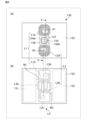
図1は、実施の形態1のRFID機能付き容器100の構成例の分解斜視図である。図1のRFID機能付き容器100は、例えば、無線通信によって商品を識別及び管理するシステムに用いられる。図1のRFID機能付き容器100は、内容物N100を収容した状態で、商品として取引される。内容物N100は、例えば、商取引の対象となる物品である。内容物N100は、液体、固体、ゾル、ゲル、又はそれらの組み合わせであり得る。内容物N100の例としては、食物、医薬品、医療又は矯正器具等が挙げられる。食物としては、ヨーグルト、プリン、インスタント食品等、容器にて提供可能な食物が挙げられる。医療又は矯正器具としては、コンタクトレンズが挙げられる。[1. Embodiment]
[1.1 Embodiment 1]
[1.1.1 Configuration]
FIG. 1 is an exploded perspective view of a configuration example of a container 100 with an RFID function according to the first embodiment. The container 100 with an RFID function shown in FIG. 1 is used, for example, in a system for identifying and managing products by wireless communication. The RFID function-equipped container 100 shown in FIG. 1 is traded as a product while containing the contents N100. The content N100 is, for example, an article to be traded. Content N100 can be a liquid, solid, sol, gel, or a combination thereof. Examples of the contents N100 include food, medicine, medical care, orthodontic equipment, and the like. Foods include foods that can be provided in containers, such as yogurt, pudding, and instant foods. Medical or orthotic devices include contact lenses.
図1のRFID機能付き容器100は、本体110と、蓋120と、RFIDモジュール130とを備える。
The container 100 with an RFID function shown in FIG. 1 includes a main body 110, a lid 120, and an RFID module 130.
図1の本体110は、内容物N100用の収容空間111を有する。本体110は、電気絶縁性を有する。本体110は、例えば、紙、樹脂材料、又はガラス等の誘電体材料から形成される。樹脂材料は、例えば、発泡スチロールを含む。図1の本体110は、有底の筒状部112と、フランジ部113とを有する。筒状部112は、収容空間111を規定する。図1の筒状部112は、円筒形状である。フランジ部113は、収容空間111の開口縁部から外方に突出する。図1のフランジ部113の外形形状は、正方形状である。
The main body 110 in FIG. 1 has a storage space 111 for the contents N100. Main body 110 has electrical insulation properties. The main body 110 is formed from, for example, paper, a resin material, or a dielectric material such as glass. The resin material includes, for example, styrofoam. The main body 110 in FIG. 1 includes a bottomed cylindrical portion 112 and a flange portion 113. The cylindrical portion 112 defines the accommodation space 111 . The cylindrical portion 112 in FIG. 1 has a cylindrical shape. The flange portion 113 projects outward from the opening edge of the housing space 111 . The outer shape of the flange portion 113 in FIG. 1 is square.
図1の蓋120は、本体110に、収容空間111の開口を覆うように取り付けられる。本実施の形態において、蓋120は、本体110に剥離可能に取り付けられる。蓋120は、本体110の収容空間111から内容物N100を取り出す際に、本体110から剥離される。蓋120は全体的に可撓性を有する。蓋120は、接着剤により本体110の収容空間111の開口の周縁部分に取り付けられる。図1では、蓋120は、本体110のフランジ部113に接着剤で取り付けられる。接着剤は、蓋120においてフランジ部113に対向する領域に塗布される。
The lid 120 in FIG. 1 is attached to the main body 110 so as to cover the opening of the accommodation space 111. In this embodiment, the lid 120 is removably attached to the main body 110. The lid 120 is peeled off from the main body 110 when the content N100 is taken out from the accommodation space 111 of the main body 110. The lid 120 is entirely flexible. The lid 120 is attached to the periphery of the opening of the accommodation space 111 of the main body 110 with adhesive. In FIG. 1, the lid 120 is attached to the flange portion 113 of the main body 110 with an adhesive. The adhesive is applied to a region of the lid 120 that faces the flange portion 113.
蓋120は、基材121と、金属膜122とを含む。基材121は、収容空間111の開口を覆う。特に、基材121は、収容空間111の開口及びフランジ部113を全体的に覆う。基材121の外形形状は、正方形状である。基材121は、例えば、紙又はプラスチック等の誘電体材料から形成される。金属膜122は、本体110の収容空間111の開口を覆う。金属膜122は、収容空間111の開口及びフランジ部113を全体的に覆う。金属膜122は、基材121における本体110側の面にある。金属膜122は、外部要因に起因する内容物の変化を防止する作用を有し得る。このように、金属膜122は、収容空間111の開口を覆うことで、内容物N100を保護する。金属膜122の材料としては、アルミニウム及びアルミニウムを含む合金が挙げられる。
Lid 120 includes a base material 121 and a metal film 122. The base material 121 covers the opening of the accommodation space 111. In particular, the base material 121 completely covers the opening of the housing space 111 and the flange portion 113. The outer shape of the base material 121 is square. The base material 121 is formed from a dielectric material such as paper or plastic, for example. The metal film 122 covers the opening of the accommodation space 111 of the main body 110. The metal film 122 completely covers the opening of the housing space 111 and the flange portion 113. The metal film 122 is on the surface of the base material 121 on the main body 110 side. The metal film 122 may have the effect of preventing changes in the contents due to external factors. In this way, the metal film 122 protects the contents N100 by covering the opening of the accommodation space 111. Examples of the material for the metal film 122 include aluminum and an alloy containing aluminum.
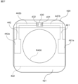
図2は、蓋120の底面図である。図2に示すように、金属膜122は、複数の部位に分割される。より詳細には、金属膜122は、金属膜122の四辺に対応する第1~第4辺部122a~122dと、収容空間111の開口を覆う中央部122eとに分割される。中央部122eは、金属膜122において収容空間111の開口を覆う所定領域R100を含む。金属膜122において、第1~第4辺部122a~122dと中央部122eとは互いに電気的に分離されている。第1~第4辺部122a~122dは、RFIDモジュール130のためのアンテナパターンとして用いることができる。金属膜122では、第1~第4辺部122a~122dのうちの隣接する2つをRFIDモジュール130のためのアンテナパターンとして用いることができる。つまり、RFIDモジュール130を蓋120の四隅のいずれに設定してもよい。そのため、RFIDモジュール130の蓋120への配置の自由度が向上する。図2では、第1及び第2辺部122a,122bが、互いに電気的に独立した第1及び第2アンテナパターンを構成する。本実施の形態では、第1辺部122aを第1アンテナパターン122aといい、第2辺部122bを第2アンテナパターン122bということがある。
FIG. 2 is a bottom view of the lid 120. As shown in FIG. 2, the metal film 122 is divided into multiple parts. More specifically, the metal film 122 is divided into first to fourth side parts 122a to 122d corresponding to the four sides of the metal film 122, and a central part 122e that covers the opening of the accommodation space 111. The central portion 122e includes a predetermined region R100 in the metal film 122 that covers the opening of the accommodation space 111. In the metal film 122, the first to fourth side parts 122a to 122d and the central part 122e are electrically isolated from each other. The first to fourth side parts 122a to 122d can be used as an antenna pattern for the RFID module 130. In the metal film 122, adjacent two of the first to fourth sides 122a to 122d can be used as an antenna pattern for the RFID module 130. That is, the RFID module 130 may be set at any of the four corners of the lid 120. Therefore, the degree of freedom in arranging the RFID module 130 on the lid 120 is improved. In FIG. 2, the first and second side portions 122a and 122b constitute first and second antenna patterns that are electrically independent from each other. In this embodiment, the first side portion 122a may be referred to as a first antenna pattern 122a, and the second side portion 122b may be referred to as a second antenna pattern 122b.
金属膜122は、金属膜122に形成されるスリット123により第1~第4辺部122a~122dと、収容空間111の開口を覆う中央部122eとに分割される。したがって、第1及び第2アンテナパターン122a,122bの形状は、金属膜122に形成されるスリット123により規定される。スリット123は、金属膜122において本体110の収容空間111の開口を覆う所定領域R100を避けて配置される。これにより、金属膜122による内容物N100の保護機能に影響を及ぼすことなく、アンテナパターン122a,122bを設けることができる。図2のスリット123は、枠部123aと、第1~第4延長部123b-1~123b-4とを含む。枠部123aは、所定領域R100を囲う矩形枠状である。枠部123aの四辺は金属膜122の四辺にそれぞれ平行している。第1~第4延長部123b-1~123b-4の各々は、枠部123aの角から金属膜122の角のうち最も近接する角に延びている。第1及び第4延長部123b-1,123b-4は蓋120の同一の対角線上に位置する。第2及び第3延長部123b-2,123b-3は蓋120の同一の対角線上に位置する。スリット123において、枠部123aは、収容空間111の開口を囲うように形成されて所定領域R100から第1及び第2アンテナパターン122a,122bを電気的に分離する第1部位である。第1延長部123b-1は、収容空間111の開口の縁部に形成されて第1及び第2アンテナパターン122a,122b間を電気的に分離する第2部位である。なお、スリット123は、金属膜122を貫通するが基材121を貫通しない。
The metal film 122 is divided by a slit 123 formed in the metal film 122 into first to fourth side parts 122a to 122d and a central part 122e that covers the opening of the accommodation space 111. Therefore, the shapes of the first and second antenna patterns 122a and 122b are defined by the slits 123 formed in the metal film 122. The slit 123 is arranged in the metal film 122 so as to avoid a predetermined region R100 that covers the opening of the accommodation space 111 of the main body 110. Thereby, the antenna patterns 122a and 122b can be provided without affecting the protection function of the metal film 122 for the contents N100. The slit 123 in FIG. 2 includes a frame portion 123a and first to fourth extension portions 123b-1 to 123b-4. The frame portion 123a has a rectangular frame shape surrounding the predetermined region R100. The four sides of the frame portion 123a are parallel to the four sides of the metal film 122, respectively. Each of the first to fourth extension parts 123b-1 to 123b-4 extends from a corner of the frame part 123a to the closest corner of the metal film 122. The first and fourth extensions 123b-1 and 123b-4 are located on the same diagonal line of the lid 120. The second and third extensions 123b-2 and 123b-3 are located on the same diagonal line of the lid 120. In the slit 123, the frame portion 123a is a first portion that is formed to surround the opening of the accommodation space 111 and electrically isolates the first and second antenna patterns 122a and 122b from the predetermined region R100. The first extension part 123b-1 is a second part formed at the edge of the opening of the accommodation space 111 to electrically isolate the first and second antenna patterns 122a and 122b. Note that the slit 123 penetrates the metal film 122 but does not penetrate the base material 121.
RFIDモジュール130は、通信周波数(キャリア周波数)を有する高周波信号で無線通信(送受信)するように構成された無線通信デバイスである。RFIDモジュール130は、例えば、UHF帯の通信用の周波数を有する高周波信号で無線通信するよう構成されている。ここでUHF帯とは、860MHzから960MHzの周波数帯域である。
The RFID module 130 is a wireless communication device configured to wirelessly communicate (transmit and receive) using a high frequency signal having a communication frequency (carrier frequency). The RFID module 130 is configured to perform wireless communication using a high frequency signal having a communication frequency in the UHF band, for example. Here, the UHF band is a frequency band from 860 MHz to 960 MHz.
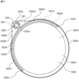
図2に示すように、RFIDモジュール130は、蓋120における所定領域R100の外側にあって金属膜122に結合される。つまり、RFIDモジュール130は、蓋120における収容空間111の開口の外側にあって金属膜122に結合される。収容空間111の開口の外側にあるとは、収容空間111の深さ方向に直交する平面において収容空間111と重ならないことをいう。RFIDモジュール130は、蓋120における本体110側(つまり、蓋120の裏側)にある。特に、RFIDモジュール130は、蓋120において本体110のフランジ部113と対向する部位にある。RFID機能付き容器100の輸送時又は陳列時等においてRFID機能付き容器100を重ねた場合、本体110の筒状部112が重なる。図3は、RFID機能付き容器100を重ねた状態を示す概略図である。RFID機能付き容器100では、上述したように、RFIDモジュール130は、蓋120において本体110のフランジ部113と対向する部位にある。そのため、RFIDモジュール130は、RFIDモジュール130が蓋120において本体110の収容空間111と重なる部位にある場合に比べて、別のRFID機能付き容器100からの影響、特に、内容物N100からの影響を受けにくい。そのため、本実施の形態のRFID機能付き容器100は、RFID機能付き容器100を重ねた場合、本体110の筒状部112が重なるので、RFIDモジュール130の機能を損ねる可能性を低減できる。
As shown in FIG. 2, the RFID module 130 is located outside a predetermined region R100 of the lid 120 and is coupled to the metal film 122. That is, the RFID module 130 is located outside the opening of the housing space 111 in the lid 120 and is coupled to the metal film 122 . Being outside the opening of the accommodation space 111 means that it does not overlap with the accommodation space 111 in a plane orthogonal to the depth direction of the accommodation space 111. The RFID module 130 is located on the main body 110 side of the lid 120 (that is, on the back side of the lid 120). In particular, the RFID module 130 is located at a portion of the lid 120 that faces the flange portion 113 of the main body 110. When the containers 100 with an RFID function are stacked on top of each other during transportation or display, the cylindrical portions 112 of the main bodies 110 overlap. FIG. 3 is a schematic diagram showing a state in which the RFID function-equipped containers 100 are stacked. In the container 100 with an RFID function, as described above, the RFID module 130 is located at a portion of the lid 120 that faces the flange portion 113 of the main body 110. Therefore, compared to the case where the RFID module 130 is located in a portion of the lid 120 that overlaps with the housing space 111 of the main body 110, the RFID module 130 is less susceptible to the influence from another container 100 with an RFID function, especially the influence from the contents N100. Hard to accept. Therefore, in the RFID function-equipped container 100 of the present embodiment, when the RFID function-equipped containers 100 are stacked, the cylindrical portion 112 of the main body 110 overlaps, so that the possibility of impairing the function of the RFID module 130 can be reduced.
RFIDモジュール130は、蓋120において、スリット123の第1延長部123b-1を跨ぐように金属膜122に結合される。より詳細には、RFIDモジュール130は、第1及び第2電極131,132を有し、第1及び第2電極131,132が第1及び第2アンテナパターン122a,122bにそれぞれ結合されるように、蓋120にある。本実施の形態では、第1及び第2電極131,132は、第1及び第2アンテナパターン122a,122bにそれぞれ容量結合される。
The RFID module 130 is coupled to the metal film 122 in the lid 120 so as to straddle the first extension 123b-1 of the slit 123. More specifically, the RFID module 130 has first and second electrodes 131 and 132, such that the first and second electrodes 131 and 132 are coupled to first and second antenna patterns 122a and 122b, respectively. , on the lid 120. In this embodiment, the first and second electrodes 131 and 132 are capacitively coupled to the first and second antenna patterns 122a and 122b, respectively.
蓋120は、保護膜124(図6参照)を備える。なお、図1及び図2では、図面の簡略化のために保護膜124を省略している。保護膜124は、金属膜122を覆う。本実施の形態では、保護膜124は、金属膜122の第1~第4辺部122a~122dと中央部122eとを包括的に覆う。保護膜124の材料は、例えば、エチレン酢酸ビニル(EVA)のようなホットメルト剤である。本実施の形態では、図5に示すように、RFIDモジュール130は、保護膜124と金属膜122との間にある。これによって、RFIDモジュール130の蓋120からの脱落の可能性を低減できる。
The lid 120 includes a protective film 124 (see FIG. 6). Note that the protective film 124 is omitted in FIGS. 1 and 2 to simplify the drawings. A protective film 124 covers the metal film 122. In this embodiment, the protective film 124 comprehensively covers the first to fourth side parts 122a to 122d and the central part 122e of the metal film 122. The material of the protective film 124 is, for example, a hot melt agent such as ethylene vinyl acetate (EVA). In this embodiment, as shown in FIG. 5, the RFID module 130 is located between the protective film 124 and the metal film 122. This can reduce the possibility of the RFID module 130 falling off the lid 120.
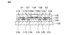
次に、図4から図6を参照して、RFIDモジュール130の構成について説明する。図4(a)はRFIDモジュール130の構成例の平面図であり、図4(b)はRFIDモジュール130の構成例の底面図である。図5は、図2のX-X線の断面図である。図6は、図4(a)のY-Y線の断面図である。図5において、X-Y-Z座標系は、発明の理解を容易にするものであって、発明を限定するものではない。X軸方向はRFIDモジュール130の長さ方向を示し、Y軸方向はRFIDモジュール130の幅方向を示し、Z軸方向はRFIDモジュール130の厚さ方向を示す。X、Y、Z方向は互いに直交する。
Next, the configuration of the RFID module 130 will be described with reference to FIGS. 4 to 6. 4(a) is a plan view of a configuration example of the RFID module 130, and FIG. 4(b) is a bottom view of the configuration example of the RFID module 130. FIG. 5 is a cross-sectional view taken along line XX in FIG. 2. FIG. 6 is a cross-sectional view taken along the YY line in FIG. 4(a). In FIG. 5, the XYZ coordinate system is used to facilitate understanding of the invention and is not intended to limit the invention. The X-axis direction indicates the length direction of the RFID module 130, the Y-axis direction indicates the width direction of the RFID module 130, and the Z-axis direction indicates the thickness direction of the RFID module 130. The X, Y, and Z directions are orthogonal to each other.
図5に示すように、RFIDモジュール130は、接着層139を介して金属膜122の第1アンテナパターン及び第2アンテナパターン122bに貼り合わされる。接着層139は、例えば、両面テープ又は合成樹脂等の接着剤で構成される。
As shown in FIG. 5, the RFID module 130 is bonded to the first antenna pattern and the second antenna pattern 122b of the metal film 122 via an adhesive layer 139. The adhesive layer 139 is made of, for example, double-sided tape or an adhesive such as synthetic resin.
図5に示すように、RFIDモジュール130は、基板133と、基板133に搭載されるRFIC素子134とを備える。基板133は、例えば、ポリイミド等のフレキシブル基板である。RFIC素子134が実装された基板133の第1面(図5では上面)には保護膜135が形成されている。保護膜135は、例えば、ポリウレタン等のエラストマや、エチレン酢酸ビニル(EVA)のようなホットメルト剤である。基板133の第2面(図5では下面)にも、保護フィルム136が貼り付けられている。保護フィルム136は、例えば、ポリイミドフィルム(カプトンテープ)等のカバーレイフィルムである。
As shown in FIG. 5, the RFID module 130 includes a substrate 133 and an RFIC element 134 mounted on the substrate 133. The substrate 133 is, for example, a flexible substrate made of polyimide or the like. A protective film 135 is formed on the first surface (upper surface in FIG. 5) of the substrate 133 on which the RFIC element 134 is mounted. The protective film 135 is, for example, an elastomer such as polyurethane or a hot melt agent such as ethylene vinyl acetate (EVA). A protective film 136 is also attached to the second surface (lower surface in FIG. 5) of the substrate 133. The protective film 136 is, for example, a coverlay film such as a polyimide film (Kapton tape).
また、基板133の第1面には、第3電極137、第4電極138、第1インダクタンス素子L1の主要部の導体パターンL1a、及び、第2インダクタンス素子L2の主要部の導体パターンL2aが形成されている。第3電極137は導体パターンL1aの一端と接続され、第4電極138は導体パターンL2aの一端と接続されている。これらの導体パターンは、例えば、銅箔をフォトリソグラフィによってパターニングすることで形成される。
Further, on the first surface of the substrate 133, a third electrode 137, a fourth electrode 138, a conductor pattern L1a of the main part of the first inductance element L1, and a conductor pattern L2a of the main part of the second inductance element L2 are formed. has been done. The third electrode 137 is connected to one end of the conductor pattern L1a, and the fourth electrode 138 is connected to one end of the conductor pattern L2a. These conductor patterns are formed, for example, by patterning copper foil using photolithography.
基板133の第2面には、金属膜122の第1辺部122a及び第2辺部122bにそれぞれ容量結合される第1電極131及び第2電極132が形成されている。また、基板133の第2面には、第1インダクタンス素子L1の一部の導体パターンL1b、第3インダクタンス素子L3の導体パターンL3a、L3b(二点鎖線で囲む導体パターン)、L3cが形成されている。これらの導体パターンも、例えば、銅箔をフォトリソグラフィによってパターニングすることで形成される。
A first electrode 131 and a second electrode 132 are formed on the second surface of the substrate 133 and are capacitively coupled to the first side 122a and second side 122b of the metal film 122, respectively. Further, on the second surface of the substrate 133, a part of the conductor pattern L1b of the first inductance element L1, conductor patterns L3a, L3b (conductor pattern surrounded by a chain double-dashed line), and L3c of the third inductance element L3 are formed. There is. These conductor patterns are also formed, for example, by patterning copper foil using photolithography.
第1インダクタンス素子L1の一部の導体パターンL1bの一端と第3インダクタンス素子L3の導体パターンL3aの一端とが第1電極131と接続されている。同様に、第2インダクタンス素子L2の導体パターンL2bの一端と第3インダクタンス素子L3の導体パターンL3cの一端とが第2電極132と接続されている。第3インダクタンス素子L3の導体パターンL3aの他端と、導体パターンL3cの他端との間には、導体パターンL3bが接続されている。
One end of a portion of the conductor pattern L1b of the first inductance element L1 and one end of the conductor pattern L3a of the third inductance element L3 are connected to the first electrode 131. Similarly, one end of the conductor pattern L2b of the second inductance element L2 and one end of the conductor pattern L3c of the third inductance element L3 are connected to the second electrode 132. A conductor pattern L3b is connected between the other end of the conductor pattern L3a of the third inductance element L3 and the other end of the conductor pattern L3c.
第1インダクタンス素子L1の導体パターンL1bの他端と、第1インダクタンス素子L1の導体パターンL1aの他端とは、ビア導体V1を介して接続されている。同様に、第2インダクタンス素子L2の導体パターンL2bの他端と、第2インダクタンス素子L2の導体パターンL2aの他端とは、ビア導体V2を介して接続されている。
The other end of the conductor pattern L1b of the first inductance element L1 and the other end of the conductor pattern L1a of the first inductance element L1 are connected via a via conductor V1. Similarly, the other end of the conductor pattern L2b of the second inductance element L2 and the other end of the conductor pattern L2a of the second inductance element L2 are connected via a via conductor V2.
基板133の第1面に形成された第3電極137及び第4電極138にRFIC素子134が搭載されている。つまり、RFIC素子134の第1端子134aが第3電極137に接続されて、RFIC素子134の第2端子134bが第4電極138に接続されている。
The RFIC element 134 is mounted on a third electrode 137 and a fourth electrode 138 formed on the first surface of the substrate 133. That is, the first terminal 134a of the RFIC element 134 is connected to the third electrode 137, and the second terminal 134b of the RFIC element 134 is connected to the fourth electrode 138.
第1インダクタンス素子L1と第3インダクタンス素子L3の導体パターンL3aとは、基板133の異なる層にそれぞれ形成され、かつ、それぞれのコイル開口が重なる関係に配置されている。同様に、第2インダクタンス素子L2及び第3インダクタンス素子L3の導体パターンL3cとは、基板133の異なる層にそれぞれ形成され、かつ、それぞれのコイル開口が重なる関係に配置されている。さらに、RFIC素子134は、基板133の面上で、第2インダクタンス素子L2及び第3インダクタンス素子L3の導体パターンL3cと、第1インダクタンス素子L1及び第3インダクタンス素子L3の導体パターンL3aとの間に、位置する。
The conductor patterns L3a of the first inductance element L1 and the third inductance element L3 are formed on different layers of the substrate 133, and are arranged such that their coil openings overlap. Similarly, the conductor patterns L3c of the second inductance element L2 and the third inductance element L3 are formed on different layers of the substrate 133, and are arranged such that their coil openings overlap. Furthermore, the RFIC element 134 is located between the conductor pattern L3c of the second inductance element L2 and the third inductance element L3 and the conductor pattern L3a of the first inductance element L1 and the third inductance element L3 on the surface of the substrate 133. ,To position.
RFIDモジュール130内において、基板133の第1面及び第2面を通る第1電流経路CP1と基板133の第2面を通る第2電流経路CP2とが形成されている。第1電流経路CP1は、第1電極131から分岐点N1、導体パターンL1b、導体パターンL1a、RFIC素子134、導体パターンL2a、導体パターンL2b、分岐点N2、を通って第2電極132に至る。第2電流経路CP2は、第1電極131から分岐点N1、導体パターンL3a、導体パターンL3b、導体パターンL3c、分岐点N2を通って第2電極132に至る。ここで、導体パターンL1aとビア導体V1を介して接続している導体パターンL1bで構成される第1インダクタンス素子L1と、導体パターンL2aとビア導体V2を介して接続している導体パターンL2bで構成される第2インダクタンス素子L2に流れる電流の巻き方向は逆になっており、第1インダクタンス素子L1で発生する磁界と第2インダクタンス素子L2で発生する磁界はお互いに打ち消し合っている。第1電流経路CP1及び第2電流経路CP2は、それぞれ、第1電極131と第2電極132との間で、互いに並列に形成されている。
Inside the RFID module 130, a first current path CP1 passing through the first and second surfaces of the substrate 133 and a second current path CP2 passing through the second surface of the substrate 133 are formed. The first current path CP1 reaches the second electrode 132 from the first electrode 131 through the branch point N1, the conductor pattern L1b, the conductor pattern L1a, the RFIC element 134, the conductor pattern L2a, the conductor pattern L2b, and the branch point N2. The second current path CP2 reaches the second electrode 132 from the first electrode 131 through the branch point N1, the conductor pattern L3a, the conductor pattern L3b, the conductor pattern L3c, and the branch point N2. Here, the first inductance element L1 is composed of a conductor pattern L1b connected to a conductor pattern L1a via a via conductor V1, and the first inductance element L1 is composed of a conductor pattern L2b connected to a conductor pattern L2a via a via conductor V2. The winding direction of the current flowing through the second inductance element L2 is opposite, and the magnetic field generated in the first inductance element L1 and the magnetic field generated in the second inductance element L2 cancel each other out. The first current path CP1 and the second current path CP2 are formed in parallel with each other between the first electrode 131 and the second electrode 132, respectively.
図1のRFID機能付き容器100では、RFIDモジュール130と金属膜122の第1及び第2アンテナパターン122a,122bとが、通信回路を構成する。金属膜122の第1及び第2アンテナパターン122a,122bは、RFIDモジュール130に対して、ダイポールアンテナとして機能する。
In the container 100 with an RFID function shown in FIG. 1, the RFID module 130 and the first and second antenna patterns 122a and 122b of the metal film 122 constitute a communication circuit. The first and second antenna patterns 122a and 122b of the metal film 122 function as dipole antennas for the RFID module 130.
次に、図7を参照して、図1のRFID機能付き容器100の通信回路の回路構成について説明する。図7は、RFID機能付き容器100の回路構成の一例の回路図である。
Next, with reference to FIG. 7, the circuit configuration of the communication circuit of the RFID function container 100 of FIG. 1 will be described. FIG. 7 is a circuit diagram of an example of the circuit configuration of the container 100 with an RFID function.
図7に示すように、RFIDモジュール130内において、第1電流経路CP1は、LC並列共振回路である並列共振回路RC1の一部であり、通信周波数の電波に対してマッチングしているので、通信周波数の電波を金属膜122が受信すると、RFIC素子134に電流が流れる。
As shown in FIG. 7, in the RFID module 130, the first current path CP1 is a part of the parallel resonant circuit RC1, which is an LC parallel resonant circuit, and is matched to the radio waves of the communication frequency. When the metal film 122 receives a radio wave of the same frequency, a current flows through the RFIC element 134.
RFIDモジュール130は、並列共振回路RC1を有する。並列共振回路RC1は、第1インダクタンス素子L1、RFIC素子134、第2インダクタンス素子L2、及び、第3インダクタンス素子L3で構成されるループ回路である。
The RFID module 130 has a parallel resonant circuit RC1. The parallel resonant circuit RC1 is a loop circuit composed of a first inductance element L1, an RFIC element 134, a second inductance element L2, and a third inductance element L3.
上述したように、RFIDモジュール130の第1及び第2電極131,132は、第1及び第2アンテナパターン122a,122bにそれぞれ容量結合される。第1電極131と第1アンテナパターン122aとの間の容量成分C1は、第1アンテナパターン122a、第1電極131、接着層139、及び保護フィルム136で構成される。第2電極132と第2アンテナパターン122bとの間の容量成分C2は、第2アンテナパターン122b、第2電極132、接着層139、及び保護フィルム136で構成される。第1アンテナパターン122aは、インダクタンス成分を有し、第4インダクタンス素子L4として作用する。第2アンテナパターン122bは、インダクタンス成分を有し、第5インダクタンス素子L5として作用する。
As described above, the first and second electrodes 131 and 132 of the RFID module 130 are capacitively coupled to the first and second antenna patterns 122a and 122b, respectively. The capacitance component C1 between the first electrode 131 and the first antenna pattern 122a includes the first antenna pattern 122a, the first electrode 131, the adhesive layer 139, and the protective film 136. The capacitance component C2 between the second electrode 132 and the second antenna pattern 122b includes the second antenna pattern 122b, the second electrode 132, the adhesive layer 139, and the protective film 136. The first antenna pattern 122a has an inductance component and acts as a fourth inductance element L4. The second antenna pattern 122b has an inductance component and acts as a fifth inductance element L5.
並列共振回路RC1は、通信周波数における電波に対してインピーダンス整合してLC並列共振するように設計されている。そのため、並列共振回路RC1は、通信周波数である固有の共振周波数の電磁波による電流をRFIC素子134に伝送するフィルタ回路として作用する。これにより、通信周波数でRFIC素子134とマッチングしており、通信周波数におけるRFIDモジュール130の通信距離を確保することができる。
The parallel resonant circuit RC1 is designed to perform LC parallel resonance by impedance matching with respect to radio waves at a communication frequency. Therefore, the parallel resonant circuit RC1 acts as a filter circuit that transmits a current generated by an electromagnetic wave having a unique resonant frequency, which is a communication frequency, to the RFIC element 134. Thereby, the communication frequency is matched with the RFIC element 134, and the communication distance of the RFID module 130 at the communication frequency can be ensured.
[1.1.2 効果等]
以上述べたように、RFID機能付き容器100は、内容物N100用の収容空間111を有する電気絶縁性の本体110と、金属膜122を含み収容空間111の開口を覆うように本体110に取り付けられる蓋120と、収容空間111の開口の外側にあるように蓋120に取り付けられ金属膜122に結合される第1及び第2電極131,132を有するRFIDモジュール130とを備える。[1.1.2 Effects, etc.]
As described above, the container 100 with an RFID function includes the electrically insulating main body 110 having the accommodation space 111 for the contents N100, and the metal film 122, and is attached to the main body 110 so as to cover the opening of the accommodation space 111. The RFID module 130 includes a lid 120 and an RFID module 130 having first and second electrodes 131 and 132 attached to the lid 120 outside the opening of the housing space 111 and coupled to the metal film 122.
RFID機能付き容器100では、蓋120の金属膜122にRFIDモジュール130が結合されることで、RFIDタグとしての機能が実現される。内容物N100の保護等のために蓋120に形成される金属膜122を利用するから、RFID機能のためだけにアンテナ等を別途設ける必要がない。RFIDモジュール130は、蓋120における収容空間111の開口の外側にあるから、意図せずにRFIDモジュール130が蓋120から脱落しても、RFIDモジュール130が内容物N100に混入される可能性を低減できる。このように、本実施の形態のRFID機能付き容器100は、内容物N100を収容する本体110に金属膜122を有する蓋120が取り付けられる容器において、意匠性の低減を抑制しつつもRFIDモジュール130が内容物N100に混入する可能性を低減できる。
In the container 100 with an RFID function, the RFID module 130 is coupled to the metal film 122 of the lid 120, thereby realizing the function as an RFID tag. Since the metal film 122 formed on the lid 120 is used to protect the contents N100, there is no need to separately provide an antenna or the like just for the RFID function. Since the RFID module 130 is located outside the opening of the housing space 111 in the lid 120, even if the RFID module 130 falls off the lid 120 unintentionally, the possibility of the RFID module 130 being mixed into the contents N100 is reduced. can. As described above, the RFID function-equipped container 100 of the present embodiment is a container in which the lid 120 having the metal film 122 is attached to the main body 110 that accommodates the contents N100, and the RFID module 130 is suppressed from deteriorating the design. It is possible to reduce the possibility of contamination with the contents N100.
RFID機能付き容器100において、金属膜122は、アンテナパターン(第1及び第2アンテナパターン122a,122b)を含む。RFIDモジュール130は、第1及び第2電極131,132がアンテナパターン(第1及び第2アンテナパターン122a,122b)に結合されるように、蓋120にある。この構成は、金属膜122がアンテナパターンを有するから、RFIDモジュール130での無線通信の効率を向上できる。
In the container 100 with an RFID function, the metal film 122 includes an antenna pattern (first and second antenna patterns 122a, 122b). The RFID module 130 is located on the lid 120 such that the first and second electrodes 131, 132 are coupled to the antenna patterns (first and second antenna patterns 122a, 122b). With this configuration, since the metal film 122 has an antenna pattern, the efficiency of wireless communication in the RFID module 130 can be improved.
RFID機能付き容器100において、アンテナパターンは、互いに電気的に独立した第1及び第2アンテナパターン122a,122bを含む。RFIDモジュール130は、第1及び第2電極131,132が第1及び第2アンテナパターン122a,122bにそれぞれ結合されるように、蓋120にある。この構成は、ダイポールアンテナを形成できる。
In the container with RFID function 100, the antenna pattern includes first and second antenna patterns 122a and 122b that are electrically independent from each other. The RFID module 130 is located on the lid 120 such that first and second electrodes 131 and 132 are coupled to the first and second antenna patterns 122a and 122b, respectively. This configuration can form a dipole antenna.
RFID機能付き容器100において、第1及び第2アンテナパターン122a,122bの形状は、金属膜122に形成されるスリット123により規定される。スリット123は、金属膜122において収容空間111の開口を覆う所定領域R100を避けて配置される。この構成は、金属膜122による内容物N100の保護機能に影響を及ぼすことなく、第1及び第2アンテナパターン122a,122bを設けることができる。
In the container 100 with an RFID function, the shapes of the first and second antenna patterns 122a and 122b are defined by the slits 123 formed in the metal film 122. The slit 123 is arranged in the metal film 122 so as to avoid a predetermined region R100 that covers the opening of the accommodation space 111. With this configuration, the first and second antenna patterns 122a and 122b can be provided without affecting the protection function of the metal film 122 for the contents N100.
RFID機能付き容器100において、スリット123は、収容空間111の開口を囲うように形成されて所定領域R100から第1及び第2アンテナパターン122a,122bを電気的に分離する第1部位123aと、収容空間111の開口の縁部に形成されて第1及び第2アンテナパターン122a,122b間を電気的に分離する第2部位123b-1~123b-4とを含む。この構成は、第1及び第2アンテナパターン122a,122bが内容物N100により影響を受ける可能性を低減できる。
In the container 100 with an RFID function, the slit 123 includes a first portion 123a that is formed to surround the opening of the accommodation space 111 and electrically isolates the first and second antenna patterns 122a and 122b from the predetermined region R100; Second portions 123b-1 to 123b-4 are formed at the edge of the opening of the space 111 to electrically isolate the first and second antenna patterns 122a and 122b. This configuration can reduce the possibility that the first and second antenna patterns 122a and 122b will be affected by the content N100.
RFID機能付き容器100において、本体110は、収容空間111の開口縁部から外方に突出するフランジ部113を有する。RFIDモジュール130は、蓋120においてフランジ部113と対向する部位にある。この構成は、RFID機能付き容器100を重ねた場合に、RFIDモジュール130の機能を損ねる可能性を低減できる。
In the container 100 with an RFID function, the main body 110 has a flange portion 113 that projects outward from the opening edge of the accommodation space 111 . The RFID module 130 is located at a portion of the lid 120 that faces the flange portion 113. This configuration can reduce the possibility that the function of the RFID module 130 will be impaired when the RFID function-equipped containers 100 are stacked.
RFID機能付き容器100において、蓋120は、金属膜122を覆う保護膜124を有する。RFIDモジュール130は、保護膜124と金属膜122との間にある。この構成は、RFIDモジュール130が蓋120から脱落する可能性を低減できる。
In the container 100 with an RFID function, the lid 120 has a protective film 124 that covers the metal film 122. RFID module 130 is between protective film 124 and metal film 122. This configuration can reduce the possibility that the RFID module 130 will fall off the lid 120.
RFID機能付き容器100において、RFIDモジュール130は、蓋120における本体110側にある。この構成は、RFID機能付き容器100の意匠性が損なわれにくくなる。この構成は、RFIDモジュール130が脱落しにくくなる。
In the container 100 with an RFID function, the RFID module 130 is located on the main body 110 side of the lid 120. With this configuration, the design of the container 100 with an RFID function is less likely to be impaired. This configuration makes it difficult for the RFID module 130 to fall off.
RFID機能付き容器100において、RFIDモジュール130は、RFIC素子134と、通信周波数である固有の共振周波数の電磁波による電流をRFIC素子134に伝送するフィルタ回路RC1とを備える。第1電極131及び第2電極132は、フィルタ回路RC1に接続される。この構成は、通信周波数でRFIC素子134と金属膜122とがマッチングしており、通信周波数におけるRFIDモジュール130の通信距離を確保することができる。
In the container 100 with an RFID function, the RFID module 130 includes an RFIC element 134 and a filter circuit RC1 that transmits a current generated by an electromagnetic wave having a unique resonance frequency, which is a communication frequency, to the RFIC element 134. The first electrode 131 and the second electrode 132 are connected to the filter circuit RC1. In this configuration, the RFIC element 134 and the metal film 122 are matched at the communication frequency, and the communication distance of the RFID module 130 at the communication frequency can be ensured.
[1.1.3 変形例]
実施の形態1は、上記構成に限定されない。実施の形態1は、その課題を達成できれば、設計等に応じて種々の変更が可能である。以下に、実施の形態1の変形例を列挙する。以下に説明する変形例は、適宜組み合わせて適用可能である。[1.1.3 Modification]
Embodiment 1 is not limited to the above configuration. Embodiment 1 can be modified in various ways depending on the design, etc., as long as the object can be achieved. Modifications of the first embodiment are listed below. The modified examples described below can be applied in combination as appropriate.
[1.1.3.1 変形例1]
図8は、実施の形態1の変形例1のRFID機能付き容器の蓋120Aの構成例の底面図である。蓋120Aは、スリット123Aが形成された金属膜122Aを含む。図8のスリット123Aは、金属膜122Aにおいて本体110の収容空間111の開口を覆う所定領域R100を避けて配置される。図8のスリット123Aは、図2のスリット123とは形状が異なる。図8のスリット123Aは、枠部123aと、第1及び第4延長部123b-1,123b-4とを含む。スリット123Aは、スリット123とは異なり、第2及び第3延長部123b-2,123b-3を含んでいない。[1.1.3.1 Modification 1]
FIG. 8 is a bottom view of a configuration example of a lid 120A of a container with an RFID function according to Modification 1 of Embodiment 1. The lid 120A includes a metal film 122A in which a slit 123A is formed. The slit 123A in FIG. 8 is arranged in the metal film 122A so as to avoid a predetermined region R100 that covers the opening of the accommodation space 111 of the main body 110. The slit 123A in FIG. 8 has a different shape from the slit 123 in FIG. The slit 123A in FIG. 8 includes a frame portion 123a and first and fourth extension portions 123b-1 and 123b-4. The slit 123A differs from the slit 123 in that it does not include the second and third extensions 123b-2 and 123b-3.
スリット123Aにより、金属膜122Aは、金属膜122Aの四辺の隣接する2つに対応する第1辺部122fと、金属膜122Aの四辺の隣接する残りの2つに対応する第2辺部122gと、収容空間111の開口を覆う中央部122eとに分割される。金属膜122Aにおいて、第1及び第2辺部122f,122gと中央部122eとは互いに電気的に分離されている。第1及び第2辺部122f,122gは、RFIDモジュール130のためのアンテナパターンとして用いることができる。図8では、第1及び第2辺部122f,122gが、互いに電気的に独立した第1及び第2アンテナパターンを構成する。以下では、第1辺部122fを第1アンテナパターン122fといい、第2辺部122gを第2アンテナパターン122gということがある。
The slit 123A allows the metal film 122A to have a first side portion 122f corresponding to two adjacent four sides of the metal film 122A, and a second side portion 122g corresponding to the remaining two adjacent four sides of the metal film 122A. , and a central portion 122e that covers the opening of the accommodation space 111. In the metal film 122A, the first and second side portions 122f, 122g and the center portion 122e are electrically isolated from each other. The first and second sides 122f and 122g can be used as an antenna pattern for the RFID module 130. In FIG. 8, the first and second side portions 122f and 122g constitute first and second antenna patterns that are electrically independent from each other. Hereinafter, the first side portion 122f may be referred to as a first antenna pattern 122f, and the second side portion 122g may be referred to as a second antenna pattern 122g.
RFIDモジュール130は、蓋120Aにおいて、スリット123Aの第1延長部123b-1を跨ぐように金属膜122Aに結合される。より詳細には、RFIDモジュール130は、第1及び第2電極131,132が第1及び第2アンテナパターン122f,122gにそれぞれ結合されるように、蓋120Aにある。第1及び第2電極131,132は、第1及び第2アンテナパターン122f,122gにそれぞれ容量結合される。
The RFID module 130 is coupled to the metal film 122A in the lid 120A so as to straddle the first extension 123b-1 of the slit 123A. More specifically, the RFID module 130 is located on the lid 120A such that the first and second electrodes 131 and 132 are coupled to the first and second antenna patterns 122f and 122g, respectively. The first and second electrodes 131 and 132 are capacitively coupled to the first and second antenna patterns 122f and 122g, respectively.
図8の蓋120Aでは、図2の蓋120に比べて、アンテナパターンを長くすることができる。これによって、アンテナパターンの長さの自由度が向上する。そのため、RFIDモジュール130の通信周波数に対応する波長に対して適した長さにアンテナパターンの長さを設定できる可能性が高くなる。RFIDモジュール130の通信周波数に対応する波長に対して適した長さは、例えば、RFIDモジュール130の通信周波数に対応する波長の1/2である。
In the lid 120A of FIG. 8, the antenna pattern can be made longer than that of the lid 120 of FIG. 2. This improves the degree of freedom in determining the length of the antenna pattern. Therefore, it is more likely that the length of the antenna pattern can be set to a length suitable for the wavelength corresponding to the communication frequency of the RFID module 130. A suitable length for the wavelength corresponding to the communication frequency of the RFID module 130 is, for example, 1/2 of the wavelength corresponding to the communication frequency of the RFID module 130.
[1.1.3.2 変形例2]
図9は、実施の形態1の変形例2のRFID機能付き容器の蓋120Bの構成例の底面図である。蓋120Bは、スリット123Bが形成された金属膜122Bを含む。図9のスリット123Bは、金属膜122Bにおいて本体110の収容空間111の開口を覆う所定領域R100を避けて配置される。図9のスリット123Bは、図2のスリット123とは形状が異なる。図9のスリット123Bは、枠部123aと、第1延長部123b-1とを含む。スリット123Bは、スリット123とは異なり、第2~第4延長部123b-2~123b-4を含んでいない。[1.1.3.2 Modification 2]
FIG. 9 is a bottom view of a configuration example of a lid 120B of a container with an RFID function according to a second modification of the first embodiment. The lid 120B includes a metal film 122B in which a slit 123B is formed. The slit 123B in FIG. 9 is arranged in the metal film 122B so as to avoid a predetermined region R100 that covers the opening of the accommodation space 111 of the main body 110. The slit 123B in FIG. 9 has a different shape from the slit 123 in FIG. The slit 123B in FIG. 9 includes a frame portion 123a and a first extension portion 123b-1. The slit 123B differs from the slit 123 in that it does not include the second to fourth extensions 123b-2 to 123b-4.
スリット123Bにより、金属膜122Bは、金属膜122Aの四辺に対応する周辺部122hと、収容空間111の開口を覆う中央部122eとに分割される。金属膜122Bにおいて、周辺部122hと中央部122eとは互いに電気的に分離されている。周辺部122hは、中央部122eを囲う形状であるが、第1延長部123b-1において分離されている。これによって、周辺部122hは、第1延長部123b-1を挟んで対向する第1及び第2端122ha,122hbを有する。周辺部122hは、RFIDモジュール130のためのループアンテナパターンとして用いることができる。以下では、周辺部122hをループアンテナパターン122hということがある。
The slit 123B divides the metal film 122B into a peripheral part 122h corresponding to the four sides of the metal film 122A and a central part 122e that covers the opening of the accommodation space 111. In the metal film 122B, the peripheral portion 122h and the central portion 122e are electrically isolated from each other. The peripheral portion 122h has a shape that surrounds the central portion 122e, but is separated at the first extension portion 123b-1. As a result, the peripheral portion 122h has first and second ends 122ha and 122hb that face each other with the first extension portion 123b-1 in between. The peripheral portion 122h can be used as a loop antenna pattern for the RFID module 130. Below, the peripheral portion 122h may be referred to as a loop antenna pattern 122h.
RFIDモジュール130は、蓋120Bにおいて、スリット123Bの第1延長部123b-1を跨ぐように金属膜122Bに結合される。より詳細には、RFIDモジュール130は、第1及び第2電極131,132がループアンテナパターン122hの第1端122ha及び第2端122hbにそれぞれ結合されるように、蓋120Bにある。第1及び第2電極131,132は、ループアンテナパターン122hの第1端122ha及び第2端122hbにそれぞれ容量結合される。
The RFID module 130 is coupled to the metal film 122B in the lid 120B so as to straddle the first extension 123b-1 of the slit 123B. More specifically, the RFID module 130 is located on the lid 120B such that the first and second electrodes 131 and 132 are coupled to the first end 122ha and second end 122hb of the loop antenna pattern 122h, respectively. The first and second electrodes 131 and 132 are capacitively coupled to a first end 122ha and a second end 122hb of the loop antenna pattern 122h, respectively.
図9の蓋120Bでは、金属膜122Bのループアンテナパターン122hは、RFIDモジュール130に対して、ループアンテナとして機能する。
In the lid 120B of FIG. 9, the loop antenna pattern 122h of the metal film 122B functions as a loop antenna for the RFID module 130.
以上述べた変形例2において、金属膜122Bは、アンテナパターン(ループアンテナパターン122h)を含む。RFIDモジュール130は、第1及び第2電極131,132がアンテナパターン(ループアンテナパターン122h)に結合されるように、蓋120Bにある。この構成は、金属膜122Bがアンテナパターンを有するから、RFIDモジュール130での無線通信の効率を向上できる。
In the second modification described above, the metal film 122B includes an antenna pattern (loop antenna pattern 122h). The RFID module 130 is located on the lid 120B such that the first and second electrodes 131, 132 are coupled to the antenna pattern (loop antenna pattern 122h). With this configuration, since the metal film 122B has an antenna pattern, the efficiency of wireless communication in the RFID module 130 can be improved.
変形例2において、アンテナパターンは、ループアンテナパターン122hを含む。RFIDモジュール130は、第1及び第2電極131,132がループアンテナパターン122hの第1及び第2端122ha,122hbにそれぞれ結合されるように、蓋120Bにある。この構成は、ループアンテナを形成できる。
In Modification 2, the antenna pattern includes a loop antenna pattern 122h. The RFID module 130 is located on the lid 120B such that the first and second electrodes 131 and 132 are respectively coupled to the first and second ends 122ha and 122hb of the loop antenna pattern 122h. This configuration can form a loop antenna.
変形例2において、ループアンテナパターン122hの形状は、金属膜122Bに形成されるスリット123Bにより規定される。スリット123Bは、金属膜122Bにおいて収容空間111の開口を覆う所定領域R100を避けて配置される。この構成は、金属膜122Bによる内容物N100の保護機能に影響を及ぼすことなく、ループアンテナパターン122hを設けることができる。
In modification 2, the shape of the loop antenna pattern 122h is defined by a slit 123B formed in the metal film 122B. The slit 123B is arranged in the metal film 122B so as to avoid a predetermined region R100 that covers the opening of the accommodation space 111. With this configuration, the loop antenna pattern 122h can be provided without affecting the protection function of the content N100 by the metal film 122B.
[1.1.3.3 変形例3]
図10は、実施の形態1の変形例3のRFID機能付き容器の蓋120Cの構成例の底面図である。蓋120Cは、スリット123Cが形成された金属膜122Cを含む。図10のスリット123Cは、金属膜122Cにおいて本体110の収容空間111の開口を覆う所定領域R100を避けて配置される。図10のスリット123Cは、図2のスリット123とは形状が異なる。図10のスリット123Cは、金属膜122Cにおいて本体110のフランジ部113に対向する角部に形成されている。スリット123Cは、第1辺部123cと、第2辺部123dと、第1及び第2延長部123e,123fとを有する。第1辺部123cは、金属膜122Cの所定の角(図10では右上の角)から金属膜122Cの中心に向かって延びている。第2辺部123dは、第1辺部123cの先端から第1辺部123cの長さ方向に直交する方向に延びている。第1及び第2延長部123e,123fは、第2辺部123dの長さ方向の両端からそれぞれ近接する金属膜122Cの辺に沿って延びている。[1.1.3.3 Modification 3]
FIG. 10 is a bottom view of a configuration example of a lid 120C of a container with an RFID function according to a third modification of the first embodiment. The lid 120C includes a metal film 122C in which a slit 123C is formed. The slit 123C in FIG. 10 is arranged in the metal film 122C so as to avoid a predetermined region R100 that covers the opening of the accommodation space 111 of the main body 110. The slit 123C in FIG. 10 has a different shape from the slit 123 in FIG. The slit 123C in FIG. 10 is formed at a corner of the metal film 122C facing the flange portion 113 of the main body 110. The slit 123C has a first side 123c, a second side 123d, and first and second extensions 123e and 123f. The first side portion 123c extends from a predetermined corner (the upper right corner in FIG. 10) of the metal film 122C toward the center of the metal film 122C. The second side portion 123d extends from the tip of the first side portion 123c in a direction perpendicular to the length direction of the first side portion 123c. The first and second extensions 123e and 123f extend along the adjacent sides of the metal film 122C from both longitudinal ends of the second side 123d.
スリット123Cにより、金属膜122Cにおけるスリット123Cの周囲にループアンテナパターン122iが形成される。ループアンテナパターン122iは、スリット123Cを囲う形状であるが、スリット123Cの第1辺部123cにおいて分離されている。これによって、ループアンテナパターン122iは、第1辺部123cを挟んで対向する第1及び第2端122ia,122ibを有する。
The slit 123C forms a loop antenna pattern 122i around the slit 123C in the metal film 122C. The loop antenna pattern 122i has a shape that surrounds the slit 123C, but is separated at the first side 123c of the slit 123C. Accordingly, the loop antenna pattern 122i has first and second ends 122ia and 122ib facing each other with the first side 123c in between.
RFIDモジュール130は、蓋120Cにおいて、スリット123Cの第1辺部123cを跨ぐように金属膜122Cに結合される。より詳細には、RFIDモジュール130は、第1及び第2電極131,132がループアンテナパターン122iの第1端122ia及び第2端122ibにそれぞれ結合されるように、蓋120Cにある。図10においても、RFIDモジュール130は、蓋120Cにおいてフランジ部113と対向する部位にある。第1及び第2電極131,132は、ループアンテナパターン122iの第1端122ia及び第2端122ibにそれぞれ容量結合される。
The RFID module 130 is coupled to the metal film 122C in the lid 120C so as to straddle the first side 123c of the slit 123C. More specifically, the RFID module 130 is on the lid 120C such that the first and second electrodes 131 and 132 are respectively coupled to the first end 122ia and the second end 122ib of the loop antenna pattern 122i. Also in FIG. 10, the RFID module 130 is located at a portion of the lid 120C that faces the flange portion 113. The first and second electrodes 131 and 132 are capacitively coupled to a first end 122ia and a second end 122ib of the loop antenna pattern 122i, respectively.
図10の蓋120Cでは、金属膜122Cのループアンテナパターン122iは、RFIDモジュール130に対して、ループアンテナとして機能する。
In the lid 120C of FIG. 10, the loop antenna pattern 122i of the metal film 122C functions as a loop antenna for the RFID module 130.
[1.1.3.4 変形例4]
図11は、実施の形態1の変形例4のRFID機能付き容器の蓋120Dの構成例の底面図である。蓋120Dは、スリット123Dが形成された金属膜122Dを含む。図11のスリット123Dは、金属膜122Dにおいて本体110の収容空間111の開口を覆う所定領域R100を避けて配置される。図11のスリット123Dは、図2のスリット123とは形状が異なる。図11のスリット123Dは、金属膜122Dにおいて本体110のフランジ部113に対向する角部に形成されている。スリット123Dは、第1辺部123gと、第2辺部123hと、第3辺部123iとを有する。第1辺部123gは、金属膜122Dの所定の角(図11では右上の角)から金属膜122Dの中心に向かって延びている。第2辺部123hは、第1辺部123gの先端から第1辺部123gの長さ方向に直交する方向に延びている。第3辺部123iは、第2辺部123hの先端から近接する金属膜122Dの辺に沿って延びている。[1.1.3.4 Modification 4]
FIG. 11 is a bottom view of a configuration example of a lid 120D of a container with an RFID function according to a fourth modification of the first embodiment. The lid 120D includes a metal film 122D in which a slit 123D is formed. The slit 123D in FIG. 11 is arranged in the metal film 122D so as to avoid a predetermined region R100 that covers the opening of the accommodation space 111 of the main body 110. The slit 123D in FIG. 11 has a different shape from the slit 123 in FIG. The slit 123D in FIG. 11 is formed at a corner of the metal film 122D that faces the flange portion 113 of the main body 110. The slit 123D has a first side 123g, a second side 123h, and a third side 123i. The first side portion 123g extends from a predetermined corner (upper right corner in FIG. 11) of the metal film 122D toward the center of the metal film 122D. The second side portion 123h extends from the tip of the first side portion 123g in a direction perpendicular to the length direction of the first side portion 123g. The third side portion 123i extends along the side of the metal film 122D adjacent to the tip of the second side portion 123h.
スリット123Dにより、金属膜122Dにおけるスリット123Dの周囲にループアンテナパターン122jが形成される。ループアンテナパターン122jは、スリット123Dを囲う形状であるが、スリット123Dの第1辺部123gにおいて分離されている。これによって、ループアンテナパターン122jは、第1辺部123gを挟んで対向する第1及び第2端122ja,122jbを有する。
The slit 123D forms a loop antenna pattern 122j around the slit 123D in the metal film 122D. The loop antenna pattern 122j has a shape that surrounds the slit 123D, but is separated at the first side 123g of the slit 123D. Accordingly, the loop antenna pattern 122j has first and second ends 122ja and 122jb facing each other with the first side portion 123g in between.
RFIDモジュール130は、蓋120Dにおいて、スリット123Dの第1辺部123gを跨ぐように金属膜122Dに結合される。より詳細には、RFIDモジュール130は、第1及び第2電極131,132がループアンテナパターン122jの第1端122ja及び第2端122jbにそれぞれ結合されるように、蓋120Dにある。図11においても、RFIDモジュール130は、蓋120Dにおいてフランジ部113と対向する部位にある。第1及び第2電極131,132は、ループアンテナパターン122jの第1端122ja及び第2端122jbにそれぞれ容量結合される。
The RFID module 130 is coupled to the metal film 122D in the lid 120D so as to straddle the first side 123g of the slit 123D. More specifically, the RFID module 130 is located on the lid 120D such that the first and second electrodes 131 and 132 are respectively coupled to the first end 122ja and the second end 122jb of the loop antenna pattern 122j. Also in FIG. 11, the RFID module 130 is located at a portion of the lid 120D that faces the flange portion 113. The first and second electrodes 131 and 132 are capacitively coupled to the first end 122ja and the second end 122jb of the loop antenna pattern 122j, respectively.
図11の蓋120Dでは、金属膜122Dのループアンテナパターン122jは、RFIDモジュール130に対して、ループアンテナとして機能する。
In the lid 120D of FIG. 11, the loop antenna pattern 122j of the metal film 122D functions as a loop antenna for the RFID module 130.
[1.1.3.5 変形例5]
図12は、実施の形態1の変形例5のRFID機能付き容器の蓋120Eの構成例の底面図である。蓋120Eは、スリット123Eが形成された金属膜122Eを含む。図12のスリット123Eは、金属膜122Eにおいて本体110の収容空間111の開口を覆う所定領域R100を避けて配置される。図12のスリット123Eは、図2のスリット123とは形状が異なる。図12のスリット123Eは、金属膜122Eにおいて収容空間111の開口の縁部に対応する部位に所定方向に沿って形成される。所定方向は、スリット123Eに近接する金属膜122Eの辺に沿った方向(図12での上下方向)である。[1.1.3.5 Modification 5]
FIG. 12 is a bottom view of a configuration example of a lid 120E of a container with an RFID function according to a fifth modification of the first embodiment. The lid 120E includes a metal film 122E in which a slit 123E is formed. The slit 123E in FIG. 12 is arranged in the metal film 122E so as to avoid a predetermined region R100 that covers the opening of the housing space 111 of the main body 110. The slit 123E in FIG. 12 has a different shape from the slit 123 in FIG. The slit 123E in FIG. 12 is formed along a predetermined direction at a portion of the metal film 122E that corresponds to the edge of the opening of the accommodation space 111. The predetermined direction is a direction along the side of the metal film 122E close to the slit 123E (vertical direction in FIG. 12).
スリット123Eにより、金属膜122Eは、金属膜122Eの四辺の一つ(図12での左辺)に対応する第1部位122kと、金属膜122Eの残りの第2部位122lとに分割される。第2部位122lは、収容空間111の開口を覆う所定領域R100を含む。金属膜122Eにおいて、第1及び第2部位122k,122lとはスリット123Eにより互いに電気的に分離されている。第1及び第2部位122k,122lは、RFIDモジュール130のためのアンテナパターンとして用いることができる。図12では、第1及び第2部位122k,122lが、互いに電気的に独立した第1及び第2アンテナパターンを構成する。以下では、第1部位122kを第1アンテナパターン122kといい、第2部位122lを第2アンテナパターン122lということがある。
The slit 123E divides the metal film 122E into a first portion 122k corresponding to one of the four sides (the left side in FIG. 12) of the metal film 122E, and a second portion 122l remaining in the metal film 122E. The second portion 122l includes a predetermined region R100 that covers the opening of the accommodation space 111. In the metal film 122E, the first and second portions 122k and 122l are electrically isolated from each other by a slit 123E. The first and second parts 122k and 122l can be used as an antenna pattern for the RFID module 130. In FIG. 12, the first and second portions 122k and 122l constitute first and second antenna patterns that are electrically independent from each other. Hereinafter, the first portion 122k may be referred to as a first antenna pattern 122k, and the second portion 122l may be referred to as a second antenna pattern 122l.
RFIDモジュール130は、蓋120Eにおいて、スリット123Eを跨ぐように金属膜122Eに結合される。より詳細には、RFIDモジュール130は、第1及び第2電極131,132が第1及び第2アンテナパターン122k,122lにそれぞれ結合されるように、蓋120Eにある。図12においても、RFIDモジュール130は、蓋120Eにおいてフランジ部113と対向する部位にある。第1及び第2電極131,132は、第1及び第2アンテナパターン122k,122lにそれぞれ容量結合される。
The RFID module 130 is coupled to the metal film 122E in the lid 120E so as to straddle the slit 123E. More specifically, the RFID module 130 is on the lid 120E such that the first and second electrodes 131, 132 are coupled to the first and second antenna patterns 122k, 122l, respectively. Also in FIG. 12, the RFID module 130 is located at a portion of the lid 120E that faces the flange portion 113. The first and second electrodes 131 and 132 are capacitively coupled to the first and second antenna patterns 122k and 122l, respectively.
図12の蓋120Eでは、金属膜122Eの第1及び第2アンテナパターン122k,122lは、RFIDモジュール130に対して、ダイポールアンテナとして機能する。
In the lid 120E of FIG. 12, the first and second antenna patterns 122k and 122l of the metal film 122E function as dipole antennas for the RFID module 130.
図12の蓋120Eでは、スリット123Eが所定方向に沿って形成されている。特に、スリット123Eが所定方向に沿って一直線上に形成されている。そのため、複数の蓋120Eにスリット123Eをまとめて形成することが可能となる。次に、図13~図15を参照して蓋120Eの製造方法の一例について説明する。蓋120Eの製造方法の一例は、第1工程、第2工程、及び第3工程を含む。
In the lid 120E of FIG. 12, a slit 123E is formed along a predetermined direction. In particular, the slits 123E are formed in a straight line along a predetermined direction. Therefore, it becomes possible to collectively form the slits 123E in the plurality of lids 120E. Next, an example of a method for manufacturing the lid 120E will be described with reference to FIGS. 13 to 15. An example of a method for manufacturing the lid 120E includes a first step, a second step, and a third step.
図13は、蓋120Eの製造方法の一例の第1工程の説明図である。第1工程は、複数の蓋120Eを形成可能な大きさのシート140を用意する。図13では、シート140は、16枚の蓋120Eを形成可能な大きさである。より詳細には、シート140は、4×4のマトリクス状に並んだ蓋120Eの形成予定領域R120を含む。シート140は、蓋120Eの基材121の基礎となる基材層に、蓋120Eの金属膜122Eの基礎となる金属層を形成して構成される。シート140における形成予定領域R120以外の部位R121は、蓋120Eには使用されない部位である。
FIG. 13 is an explanatory diagram of the first step of an example of the method for manufacturing the lid 120E. In the first step, a sheet 140 of a size capable of forming a plurality of lids 120E is prepared. In FIG. 13, the sheet 140 is large enough to form 16 lids 120E. More specifically, the sheet 140 includes regions R120 where the lids 120E are to be formed, arranged in a 4×4 matrix. The sheet 140 is constructed by forming a metal layer, which is the basis of the metal film 122E of the lid 120E, on a base material layer which is the basis of the base material 121 of the lid 120E. A region R121 other than the intended formation region R120 on the sheet 140 is a region that is not used for the lid 120E.
図14は、蓋120Eの製造方法の一例の第2工程の説明図である。第2工程は、第1工程で用意したシート140の金属層に溝150を形成する。溝150において各形成予定領域R120に対応する部分がスリット123Eとなる。図14では、所定方向に並ぶ複数(図14では4つ)の形成予定領域R120に、所定方向に沿った1つの溝150が形成される。これによって、複数(図14では4つ)のスリット123Eがまとめて形成される。
FIG. 14 is an explanatory diagram of the second step of an example of the method for manufacturing the lid 120E. In the second step, grooves 150 are formed in the metal layer of the sheet 140 prepared in the first step. A portion of the groove 150 corresponding to each formation planned region R120 becomes a slit 123E. In FIG. 14, one groove 150 along a predetermined direction is formed in a plurality of (four in FIG. 14) planned formation regions R120 lined up in a predetermined direction. As a result, a plurality of (four in FIG. 14) slits 123E are formed at once.
図15は、蓋120Eの製造方法の一例の第3工程の説明図である。第3工程は、複数の蓋120Eの形成予定領域R120に複数のRFIDモジュール130をそれぞれ配置する。
FIG. 15 is an explanatory diagram of the third step in an example of the method for manufacturing the lid 120E. In the third step, a plurality of RFID modules 130 are respectively arranged in the formation region R120 of the plurality of lids 120E.
第3工程の後、シート140は切断されて、複数の蓋120Eに分離される。シート140の切断は、シート140を複数の本体110にまとめて貼り付けた後に実行されてよい。
After the third step, the sheet 140 is cut and separated into a plurality of lids 120E. The cutting of the sheet 140 may be performed after the sheet 140 is attached to the plurality of bodies 110 together.
以上述べた変形例5では、スリット123Eは、金属膜122Eにおける収容空間111の開口の縁部に対応する部位に所定方向に沿って形成されて第1及び第2アンテナパターン122k,122l間を電気的に分離する。この構成は、複数の蓋120Eへのスリット123Eの形成をまとめて行うことを可能にする。
In the fifth modification described above, the slit 123E is formed along a predetermined direction at a portion of the metal film 122E that corresponds to the edge of the opening of the accommodation space 111, and electrically connects the first and second antenna patterns 122k and 122l. to separate. This configuration makes it possible to form slits 123E in multiple lids 120E at once.
[1.2 実施の形態2]
[1.2.1 構成]
図16は、実施の形態2のRFID機能付き容器200の構成例の分解斜視図である。図16のRFID機能付き容器200は、複数の容器を1組として構成されている。図16のRFID機能付き容器200は、例えば、4個1パックで取引される商品に利用できる。[1.2 Embodiment 2]
[1.2.1 Configuration]
FIG. 16 is an exploded perspective view of a configuration example of a container 200 with an RFID function according to the second embodiment. The container 200 with an RFID function shown in FIG. 16 is configured as a set of a plurality of containers. The container 200 with an RFID function shown in FIG. 16 can be used, for example, for products that are traded in packs of four.
図16のRFID機能付き容器200は、本体210と、蓋220と、RFIDモジュール230とを備える。
The container 200 with an RFID function shown in FIG. 16 includes a main body 210, a lid 220, and an RFID module 230.
図16の本体210は、内容物N100用の複数(図16では4つ)の収容空間211を有する。本体210は、電気絶縁性を有する。本体210は、例えば、紙、プラスチック、又はガラス等の誘電体材料から形成される。
The main body 210 in FIG. 16 has a plurality of (four in FIG. 16) accommodation spaces 211 for the contents N100. Main body 210 has electrical insulation properties. Body 210 is formed from a dielectric material such as paper, plastic, or glass, for example.
図16の本体210は、複数(図16では4つ)の小本体部215a~215dを有する。複数の小本体部215a~215dの各々は、有底の筒状部212と、フランジ部213とを有する。筒状部212は、収容空間211を規定する。図16の筒状部212は、円筒形状である。フランジ部213は、収容空間211の開口縁部から外方に突出する。図16のフランジ部213の外形形状は、正方形状である。
The main body 210 in FIG. 16 has a plurality of (four in FIG. 16) small main body parts 215a to 215d. Each of the plurality of small body parts 215a to 215d has a bottomed cylindrical part 212 and a flange part 213. The cylindrical portion 212 defines the accommodation space 211 . The cylindrical portion 212 in FIG. 16 has a cylindrical shape. The flange portion 213 projects outward from the opening edge of the housing space 211 . The outer shape of the flange portion 213 in FIG. 16 is square.
4つの小本体部215は、収容空間211が所定の部位を囲うように配置される。図16では、所定の部位は、本体210の中央部である。本実施の形態では、4つの小本体部215a~215dは、2×2のマトリクス状に配置されている。本体210の中央部には、4つの小本体部215a~215dで囲まれた開口216がある。4つの小本体部215a~215dは、フランジ部213で互いに連結されている。隣接する小本体部215a,215bのフランジ部213間には、ミシン目214aが形成される。ミシン目214aは、小本体部215a,215b同士を分離するために用いられる。隣接する小本体部215a,215cのフランジ部213間には、ミシン目214bが形成される。ミシン目214bは、小本体部215a,215c同士を分離するために用いられる。隣接する小本体部215c,215dのフランジ部213間には、ミシン目214cが形成される。ミシン目214cは、小本体部215c,215d同士を分離するために用いられる。隣接する小本体部215b,215dのフランジ部213間には、ミシン目214dが形成される。ミシン目214dは、小本体部215b,215d同士を分離するために用いられる。ミシン目214a~214dの各々は、本体210において一対の収容空間211の間に、一対の収容空間211が隣接する方向に交差する方向に並ぶ複数のスリットで構成される。本体210のミシン目(第1ミシン目)214a~214dによって小本体部215a~215d同士を切り離すことが可能である。
The four small main body parts 215 are arranged so that the accommodation space 211 surrounds a predetermined region. In FIG. 16, the predetermined region is the central portion of main body 210. In FIG. In this embodiment, the four small main body parts 215a to 215d are arranged in a 2×2 matrix. At the center of the main body 210 is an opening 216 surrounded by four small main body parts 215a to 215d. The four small main body parts 215a to 215d are connected to each other by a flange part 213. A perforation 214a is formed between the flange portions 213 of the adjacent small main body portions 215a, 215b. The perforations 214a are used to separate the small body parts 215a and 215b from each other. A perforation 214b is formed between the flange portions 213 of the adjacent small main body portions 215a and 215c. The perforations 214b are used to separate the small body parts 215a and 215c from each other. A perforation 214c is formed between the flange portions 213 of the adjacent small main body portions 215c and 215d. The perforation 214c is used to separate the small body parts 215c and 215d from each other. A perforation 214d is formed between the flange portions 213 of the adjacent small main body portions 215b and 215d. The perforations 214d are used to separate the small body parts 215b and 215d from each other. Each of the perforations 214a to 214d is constituted by a plurality of slits arranged between the pair of accommodation spaces 211 in the main body 210 in a direction intersecting the direction in which the pair of accommodation spaces 211 are adjacent to each other. The small body parts 215a to 215d can be separated from each other by perforations (first perforations) 214a to 214d in the main body 210.
図16の蓋220は、本体210に、複数の収容空間211の開口を覆うように取り付けられる。図16の蓋220は、剥離可能に本体210に取り付けられる。蓋220は、本体210の収容空間211から内容物N100を取り出す際に、本体210から剥離される。蓋220は全体的に可撓性を有する。
The lid 220 in FIG. 16 is attached to the main body 210 so as to cover the openings of the plurality of accommodation spaces 211. The lid 220 in FIG. 16 is releasably attached to the main body 210. The lid 220 is peeled off from the main body 210 when the content N100 is taken out from the storage space 211 of the main body 210. The lid 220 is entirely flexible.
図16の蓋220は、複数(図16では4つ)の小蓋部225a~225dを有する。複数の小蓋部225a~225dは、本体210の複数の小本体部215a~215dにそれぞれ対応する。RFID機能付き容器200では、小本体部215a~215dと、小本体部215a~215dに対応する小蓋部225a~225dとが、小容器を構成する。蓋220は、基材221と、金属膜222とを含む。基材221は、複数の小本体部215a~215dの収容空間211の開口を覆う。特に、基材221は、複数の小本体部215a~215dの収容空間211の開口及びフランジ部213を全体的に覆う。基材221の外形形状は、正方形状である。基材221は、例えば、紙又はプラスチック等の誘電体材料から形成される。金属膜222は、複数の小本体部215a~215dの収容空間211の開口を包括的に覆う。金属膜222は、複数の小本体部215a~215dの収容空間211の開口及びフランジ部213を包括的に覆う。金属膜222は、基材221における本体210側の面にある。金属膜222は、外部要因に起因する内容物の変化を防止する作用を有し得る。このように、金属膜222は、小本体部215の収容空間211の開口を覆うことで、内容物N100を保護する。金属膜222の材料としては、アルミニウム及びアルミニウムを含む合金が挙げられる。
The lid 220 in FIG. 16 has a plurality of (four in FIG. 16) small lid portions 225a to 225d. The plurality of small lid portions 225a to 225d correspond to the plurality of small body portions 215a to 215d of the main body 210, respectively. In the container with RFID function 200, the small body parts 215a to 215d and the small lid parts 225a to 225d corresponding to the small body parts 215a to 215d constitute a small container. Lid 220 includes a base material 221 and a metal film 222. The base material 221 covers the openings of the accommodation spaces 211 of the plurality of small main body parts 215a to 215d. In particular, the base material 221 entirely covers the openings of the accommodation spaces 211 and the flange portions 213 of the plurality of small main body portions 215a to 215d. The outer shape of the base material 221 is square. The base material 221 is formed from a dielectric material such as paper or plastic, for example. The metal film 222 comprehensively covers the openings of the accommodation spaces 211 of the plurality of small main body parts 215a to 215d. The metal film 222 comprehensively covers the openings of the housing spaces 211 and the flange portions 213 of the plurality of small main body portions 215a to 215d. The metal film 222 is on the surface of the base material 221 on the main body 210 side. The metal film 222 may have the effect of preventing changes in the contents due to external factors. In this way, the metal film 222 protects the contents N100 by covering the opening of the accommodation space 211 of the small body portion 215. Examples of the material of the metal film 222 include aluminum and an alloy containing aluminum.
4つの小蓋部225a~225dは、2×2のマトリクス状に配置されている。蓋220の中央には、4つの小蓋部225a~225dで囲まれた開口226がある。開口226は、蓋220において、本体210の所定の部位(中央部)に対応する位置にある。4つの小蓋部225a~225dは、互いに連結されている。蓋220において隣接する小蓋部225a,225b間には、ミシン目224aが形成される。ミシン目224aは、小蓋部225a,225b同士を分離するために用いられる。蓋220において隣接する小蓋部225a,225c間には、ミシン目224bが形成される。ミシン目224bは、小蓋部225a,225c同士を分離するために用いられる。蓋220において隣接する小蓋部225c,225d間には、ミシン目224cが形成される。ミシン目224cは、小蓋部225c,225d同士を分離するために用いられる。蓋220において隣接する小蓋部225b,225d間には、ミシン目224dが形成される。ミシン目224dは、小蓋部225b,225d同士を分離するために用いられる。ミシン目224a~224dは、蓋220において本体210のミシン目214a~214dと重なる位置に形成される。よって、ミシン目224a~224dの各々は、本体210において一対の収容空間211の間に、一対の収容空間211が隣接する方向に交差する方向に並ぶ複数のスリットで構成される。蓋220のミシン目(第2ミシン目)224a~224dによって小蓋部225a~225d同士を切り離すことが可能である。
The four small lid portions 225a to 225d are arranged in a 2×2 matrix. At the center of the lid 220 is an opening 226 surrounded by four small lid parts 225a to 225d. The opening 226 is located in the lid 220 at a position corresponding to a predetermined portion (center) of the main body 210. The four small lid parts 225a to 225d are connected to each other. A perforation 224a is formed in the lid 220 between adjacent small lid portions 225a and 225b. The perforation 224a is used to separate the small lid portions 225a and 225b from each other. A perforation 224b is formed between the adjacent small lid portions 225a and 225c in the lid 220. The perforations 224b are used to separate the small lid portions 225a and 225c from each other. A perforation 224c is formed between the adjacent small lid portions 225c and 225d in the lid 220. The perforation 224c is used to separate the small lid portions 225c and 225d from each other. A perforation 224d is formed between the adjacent small lid portions 225b and 225d in the lid 220. The perforations 224d are used to separate the small lid portions 225b and 225d from each other. The perforations 224a to 224d are formed in the lid 220 at positions that overlap the perforations 214a to 214d of the main body 210. Therefore, each of the perforations 224a to 224d is constituted by a plurality of slits arranged between the pair of accommodation spaces 211 in the main body 210 in a direction intersecting the direction in which the pair of accommodation spaces 211 are adjacent to each other. The small lid parts 225a to 225d can be separated from each other by the perforations (second perforations) 224a to 224d of the lid 220.
蓋220は、接着剤により小蓋部225a~225dを小本体部215a~215dの収容空間211の開口の周縁部分に取り付けることで、本体210に取り付けられる。図16では、小蓋部225a~225dは、小本体部215a~215dのフランジ部213に接着剤で取り付けられる。接着剤は、小蓋部225a~225dにおいてフランジ部213に対向する領域に塗布される。つまり、ミシン目214a~214d,224a~224dによって、RFID機能付き容器200を、小本体部215a~215dと小蓋部225a~225dとで構成される小容器に分離した際にも、各小容器では小蓋部225a~225dが小本体部215a~215dに接着剤で取り付けられた状態となっている。
The lid 220 is attached to the main body 210 by attaching the small lid parts 225a to 225d to the periphery of the opening of the accommodation space 211 of the small main body parts 215a to 215d using adhesive. In FIG. 16, the small lid portions 225a to 225d are attached to the flange portions 213 of the small main body portions 215a to 215d with adhesive. The adhesive is applied to areas of the small lids 225a to 225d that face the flange 213. In other words, even when the RFID function-equipped container 200 is separated into small containers consisting of the small body parts 215a to 215d and the small lid parts 225a to 225d by the perforations 214a to 214d and 224a to 224d, each small container In this case, the small lid parts 225a to 225d are attached to the small main body parts 215a to 215d with adhesive.
図17は、蓋220の底面図である。図17に示すように、金属膜222は、蓋220における本体210側の全面にあって、本体210の複数の収容空間211を包括的に覆う。蓋220には中央に開口226があるため、開口226に対応する部位には金属膜222が存在しない。金属膜222には、スリット223が形成される。図17のスリット223は、金属膜222において本体210の収容空間211の開口を覆う所定領域R200を避けて配置される。図17のスリット223は、金属膜222において本体210の小本体部215aのフランジ部213に対向する角部に形成されている。スリット223は、開口226から反対側の角部に向かって延びている。
FIG. 17 is a bottom view of the lid 220. As shown in FIG. 17, the metal film 222 is located on the entire surface of the lid 220 on the main body 210 side, and comprehensively covers the plurality of accommodation spaces 211 of the main body 210. Since the lid 220 has an opening 226 in the center, the metal film 222 is not present in a portion corresponding to the opening 226. A slit 223 is formed in the metal film 222. The slit 223 in FIG. 17 is arranged in the metal film 222 so as to avoid a predetermined region R200 that covers the opening of the housing space 211 of the main body 210. The slit 223 in FIG. 17 is formed at a corner of the metal film 222 facing the flange portion 213 of the small body portion 215a of the main body 210. The slit 223 extends from the opening 226 toward the opposite corner.
スリット223により、金属膜222における開口226の周囲にループアンテナパターン222aが形成される。ループアンテナパターン222aによって、図17において両矢印Aで示すように電流が流れる経路が発生し得る。ループアンテナパターン222aは、開口226を囲う形状であるが、スリット223において部分的に分離されている。これによって、ループアンテナパターン222aは、スリット223を挟んで対向する第1及び第2端222aa,222abを有する。
A loop antenna pattern 222a is formed around the opening 226 in the metal film 222 by the slit 223. The loop antenna pattern 222a can generate a path through which current flows, as shown by double-headed arrows A in FIG. The loop antenna pattern 222a has a shape that surrounds the opening 226, but is partially separated at the slit 223. Accordingly, the loop antenna pattern 222a has first and second ends 222aa and 222ab facing each other with the slit 223 in between.
RFIDモジュール230は、RFID130と同じである。RFIDモジュール230は、蓋220において、スリット223を跨ぐように金属膜222に結合される。より詳細には、RFIDモジュール230は、第1及び第2電極231,232がループアンテナパターン222aの第1端222aa及び第2端222abにそれぞれ結合されるように、蓋220にある。図17においても、RFIDモジュール230は、蓋220においてフランジ部213と対向する部位にある。第1及び第2電極231,232は、ループアンテナパターン222aの第1端222aa及び第2端222abにそれぞれ容量結合される。
RFID module 230 is the same as RFID 130. The RFID module 230 is coupled to the metal film 222 in the lid 220 so as to straddle the slit 223 . More specifically, the RFID module 230 is on the lid 220 such that the first and second electrodes 231 and 232 are respectively coupled to the first end 222aa and the second end 222ab of the loop antenna pattern 222a. Also in FIG. 17, the RFID module 230 is located at a portion of the lid 220 that faces the flange portion 213. The first and second electrodes 231 and 232 are capacitively coupled to a first end 222aa and a second end 222ab of the loop antenna pattern 222a, respectively.
図17のRFID機能付き容器200では、RFID機能付き容器200が小容器に分離される前は、金属膜222のループアンテナパターン222aが、RFIDモジュール230に対して、ループアンテナとして機能する。つまり、複数の収容空間211が個別に分離される前は、RFIDモジュール230は金属膜222を利用して通信可能である。一方で、RFID機能付き容器200が小容器に分離されると、金属膜222がミシン目224で分離されることでループアンテナパターン222aが破損するから、ループアンテナパターン222aは、RFIDモジュール230に対して、ループアンテナとして機能しなくなる。そのため、RFID機能付き容器200が小容器に分離された後には、RFID機能が機能しなくなる。つまり、複数の収容空間211が個別に分離された後は、RFIDモジュール230は金属膜222を利用して通信できなくなる。
In the RFID function container 200 of FIG. 17, the loop antenna pattern 222a of the metal film 222 functions as a loop antenna for the RFID module 230 before the RFID function container 200 is separated into small containers. That is, before the plurality of accommodation spaces 211 are separated, the RFID module 230 can communicate using the metal film 222. On the other hand, when the container with RFID function 200 is separated into small containers, the metal film 222 is separated at the perforations 224 and the loop antenna pattern 222a is damaged. It will no longer function as a loop antenna. Therefore, after the container 200 with the RFID function is separated into small containers, the RFID function no longer functions. That is, after the plurality of accommodation spaces 211 are separated, the RFID module 230 cannot communicate using the metal film 222.
[1.2.2 効果等]
以上述べたRFID機能付き容器200では、本体210は、所定の部位を囲うように配置される複数の収容空間211を有する。金属膜222は、複数の収容空間211を包括的に覆う。蓋220において所定の部位に対応する位置に開口226が形成される。金属膜222には開口226から延びるスリット223が形成される。RFIDモジュール230は、スリット223を跨ぐように蓋220にある。この構成は、各々内容物N100を収容する複数の収容空間211を有する本体210に金属膜222を有する蓋220が取り付けられる容器において、意匠性の低減を抑制しつつもRFIDモジュール230が内容物N100に混入する可能性を低減できる。また、複数の収容空間211が個別に分離される前は、RFIDモジュール230は金属膜222を利用して通信可能である。一方で、複数の収容空間211が個別に分離された後は、RFIDモジュール230は金属膜222を利用して通信できなくなる。[1.2.2 Effects, etc.]
In the container 200 with an RFID function described above, the main body 210 has a plurality of accommodation spaces 211 arranged so as to surround a predetermined region. The metal film 222 comprehensively covers the plurality of accommodation spaces 211 . An opening 226 is formed in the lid 220 at a position corresponding to a predetermined region. A slit 223 extending from an opening 226 is formed in the metal film 222 . The RFID module 230 is located on the lid 220 so as to straddle the slit 223. With this configuration, in a container in which a lid 220 having a metal film 222 is attached to a main body 210 having a plurality of accommodation spaces 211 each accommodating contents N100, the RFID module 230 can suppress deterioration of the design while allowing the RFID module 230 to accommodate contents N100. The possibility of contamination can be reduced. Further, before the plurality of accommodation spaces 211 are separated into individual spaces, the RFID module 230 can communicate using the metal film 222. On the other hand, after the plurality of accommodation spaces 211 are separated, the RFID module 230 is no longer able to communicate using the metal film 222.
[1.2.3 変形例]
実施の形態2は、上記構成に限定されない。実施の形態2は、その課題を達成できれば、設計等に応じて種々の変更が可能である。次に、実施の形態2の一変形例のRFID機能付き容器について説明する。本変形例は、図18に示す蓋220Aを備える点で、実施の形態2のRFID機能付き容器200と異なる。図18は、実施の形態2の一変形例のRFID機能付き容器の蓋220Aの構成例の底面図である。[1.2.3 Variations]
Embodiment 2 is not limited to the above configuration. The second embodiment can be modified in various ways depending on the design, etc., as long as the object can be achieved. Next, a container with an RFID function according to a modified example of the second embodiment will be described. This modification differs from the RFID function-equipped container 200 of the second embodiment in that it includes a lid 220A shown in FIG. 18. FIG. 18 is a bottom view of a configuration example of a lid 220A of a container with an RFID function according to a modified example of the second embodiment.
図18の蓋220Aは、本体210に、複数の収容空間211の開口を覆うように取り付けられる。図18の蓋220Aは、剥離可能に本体210に取り付けられる。蓋220Aは、本体210の収容空間211から内容物N100を取り出す際に、本体210から剥離される。蓋220Aは全体的に可撓性を有する。
The lid 220A in FIG. 18 is attached to the main body 210 so as to cover the openings of the plurality of accommodation spaces 211. The lid 220A in FIG. 18 is removably attached to the main body 210. The lid 220A is peeled off from the main body 210 when the content N100 is taken out from the storage space 211 of the main body 210. The lid 220A is entirely flexible.
図17の蓋220Aは、基材221Aと、金属膜222Aとを含む。金属膜222Aは、蓋220における本体210側の全面にあって、本体210の複数の収容空間211を包括的に覆う。図17の蓋220Aは、図16の蓋220と同様に、複数の小蓋部225a~225dを有する。4つの小蓋部225a~225dは、2×2のマトリクス状に配置されている。上述したように、蓋220Aにおいて、隣接する小蓋部225a,225b間、隣接する小蓋部225a,225c間、隣接する小蓋部225c,225d間、及び、隣接する小蓋部225b,225d間には、それぞれ、ミシン目224a~224dが形成される。ミシン目224a~224dの各々は、複数のスリットで構成される。複数のスリットの大きさ及び複数のスリットの間隔を適宜設定することで、ミシン目224a~224dの各々は、隣接する小蓋部間を実質的に電気的に分離するように構成されている。
The lid 220A in FIG. 17 includes a base material 221A and a metal film 222A. The metal film 222A is located on the entire surface of the lid 220 on the main body 210 side, and comprehensively covers the plurality of accommodation spaces 211 of the main body 210. The lid 220A in FIG. 17 has a plurality of small lid portions 225a to 225d, similar to the lid 220 in FIG. 16. The four small lid portions 225a to 225d are arranged in a 2×2 matrix. As described above, in the lid 220A, between the adjacent small lid parts 225a and 225b, between the adjacent small lid parts 225a and 225c, between the adjacent small lid parts 225c and 225d, and between the adjacent small lid parts 225b and 225d. Perforations 224a to 224d are formed in each of the holes 224a to 224d. Each of the perforations 224a to 224d is composed of a plurality of slits. By appropriately setting the size of the plurality of slits and the interval between the plurality of slits, each of the perforations 224a to 224d is configured to substantially electrically isolate adjacent small lid portions.
ミシン目224aにより、金属膜222Aにおける小蓋部225a,225bにそれぞれ対応する部位を電気的に分離されたアンテナパターンとして利用できる。ミシン目224bにより、金属膜222Aにおける小蓋部225a,225cにそれぞれ対応する部位を電気的に分離されたアンテナパターンとして利用できる。ミシン目224cにより、金属膜222Aにおける小蓋部225c,225dにそれぞれ対応する部位を電気的に分離されたアンテナパターンとして利用できる。ミシン目224dにより、金属膜222Aにおける小蓋部225b,225dにそれぞれ対応する部位を電気的に分離されたアンテナパターンとして利用できる。
The perforations 224a allow the portions of the metal film 222A corresponding to the small lid portions 225a and 225b to be used as electrically isolated antenna patterns. The perforations 224b allow the portions of the metal film 222A corresponding to the small lid portions 225a and 225c to be used as electrically isolated antenna patterns. The perforations 224c allow the portions of the metal film 222A corresponding to the small lid portions 225c and 225d to be used as electrically isolated antenna patterns. The perforations 224d allow the portions of the metal film 222A corresponding to the small lid portions 225b and 225d to be used as electrically isolated antenna patterns.
図18に示すように、RFIDモジュール230は、蓋220Aにおける所定領域R200の外側にあって金属膜222Aに結合される。RFIDモジュール230は、蓋220Aにおいて本体210のフランジ部213と対向する部位にある。RFIDモジュール230は、蓋220Aにおいて、ミシン目224bを跨ぐように金属膜222Aに結合される。より詳細には、RFIDモジュール230は、第1及び第2電極231,232が金属膜222Aにおける小蓋部225a,225cにそれぞれ対応する部位にそれぞれ結合されるように、蓋220Aにある。この場合、金属膜222Aにおける小蓋部225a,225cにそれぞれ対応する部位が第1及び第2アンテナパターンとして機能する。第1及び第2電極231,232は、第1及び第2アンテナパターンにそれぞれ容量結合される。
As shown in FIG. 18, the RFID module 230 is located outside a predetermined region R200 in the lid 220A and is coupled to the metal film 222A. The RFID module 230 is located at a portion of the lid 220A that faces the flange portion 213 of the main body 210. The RFID module 230 is coupled to the metal film 222A in the lid 220A so as to straddle the perforation 224b. More specifically, the RFID module 230 is located on the lid 220A such that the first and second electrodes 231 and 232 are respectively coupled to portions of the metal film 222A that correspond to the small lid portions 225a and 225c, respectively. In this case, portions of the metal film 222A corresponding to the small lid portions 225a and 225c, respectively, function as the first and second antenna patterns. The first and second electrodes 231 and 232 are capacitively coupled to the first and second antenna patterns, respectively.
本変形例では、RFID機能付き容器が小容器に分離される前は、金属膜222Aの第1及び第2アンテナパターンが、RFIDモジュール230に対して、ダイポールアンテナとして機能する。つまり、複数の収容空間211が個別に分離される前は、RFIDモジュール230は金属膜222Aを利用して通信可能である。一方で、RFID機能付き容器が小容器に分離されると、金属膜222Aがミシン目224で分離されることで第1及び第2アンテナパターンの少なくとも一方とRFIDモジュール230との結合が維持できなくなる。場合によっては、RFIDモジュール230が蓋220Aから脱落する。これにより、金属膜222Aは、RFIDモジュール230に対して、ダイポールアンテナとして機能しなくなる。そのため、RFID機能付き容器が小容器に分離された後には、RFID機能が機能しなくなる。つまり、複数の収容空間211が個別に分離された後は、RFIDモジュール230は金属膜222Aを利用して通信できなくなる。
In this modification, the first and second antenna patterns of the metal film 222A function as dipole antennas for the RFID module 230 before the container with the RFID function is separated into small containers. That is, before the plurality of accommodation spaces 211 are separated into individual spaces, the RFID module 230 can communicate using the metal film 222A. On the other hand, when the container with the RFID function is separated into small containers, the metal film 222A is separated at the perforations 224, making it impossible to maintain the coupling between at least one of the first and second antenna patterns and the RFID module 230. . In some cases, the RFID module 230 falls off the lid 220A. As a result, the metal film 222A no longer functions as a dipole antenna for the RFID module 230. Therefore, after the container with the RFID function is separated into small containers, the RFID function no longer functions. That is, after the plurality of accommodation spaces 211 are separated, the RFID module 230 cannot communicate using the metal film 222A.
以上述べた変形例において、本体210は、それぞれ収容空間211を有する一対の小本体部215a,215bと、一対の小本体部215a,215b同士を分離するための第1ミシン目214aとを有する。蓋220は、一対の小本体部215a,215bにそれぞれ対応する一対の小蓋部225a,225bと、一対の小蓋部225a,225b同士を分離するための第2ミシン目224aとを有する。第2ミシン目224aは、金属膜222において一対の小蓋部225a,225bに対応する部分同士を電気的に分離する。RFIDモジュール230は、第2ミシン目224aを跨ぐように蓋220Aにある。この構成は、各々内容物N100を収容する複数の収容空間211を有する本体210に金属膜222Aを有する蓋220Aが取り付けられる容器において、意匠性の低減を抑制しつつもRFIDモジュール230が内容物N100に混入する可能性を低減できる。また、複数の収容空間211が個別に分離される前は、RFIDモジュール230は金属膜222Aを利用して通信可能である。一方で、複数の収容空間211が個別に分離された後は、RFIDモジュール230は金属膜222Aを利用して通信できなくなる。
In the modification described above, the main body 210 includes a pair of small main body parts 215a and 215b each having a housing space 211, and a first perforation 214a for separating the pair of small main body parts 215a and 215b. The lid 220 has a pair of small lid parts 225a, 225b corresponding to the pair of small main body parts 215a, 215b, respectively, and a second perforation 224a for separating the pair of small lid parts 225a, 225b. The second perforation 224a electrically separates the portions of the metal film 222 that correspond to the pair of small lids 225a and 225b. The RFID module 230 is located on the lid 220A so as to straddle the second perforation 224a. With this configuration, in a container in which a lid 220A having a metal film 222A is attached to a main body 210 having a plurality of accommodation spaces 211 each accommodating contents N100, the RFID module 230 can accommodate contents N100 while suppressing deterioration in design. The possibility of contamination can be reduced. Furthermore, before the plurality of accommodation spaces 211 are separated into individual spaces, the RFID module 230 can communicate using the metal film 222A. On the other hand, after the plurality of accommodation spaces 211 are individually separated, the RFID module 230 is no longer able to communicate using the metal film 222A.
[1.3 実施の形態3]
[1.3.1 構成]
図19は、実施の形態3のRFID機能付き容器300の構成例の分解斜視図である。[1.3 Embodiment 3]
[1.3.1 Configuration]
FIG. 19 is an exploded perspective view of a configuration example of a container 300 with an RFID function according to the third embodiment.
図19のRFID機能付き容器300は、本体310と、蓋320と、RFIDモジュール330とを備える。RFIDモジュール330は、実施の形態1のRFIDモジュール130と同一である。
The container 300 with an RFID function shown in FIG. 19 includes a main body 310, a lid 320, and an RFID module 330. RFID module 330 is the same as RFID module 130 of the first embodiment.
図19の本体310は、内容物N100用の収容空間311を有する。本体310は、電気絶縁性を有する。本体310は、例えば、紙、樹脂材料、又はガラス等の誘電体材料から形成される。樹脂材料は、例えば、発泡スチロールを含む。図19の本体310は、有底の筒状である。図19の本体310は、底にいくほど直径が小さくなる円筒形状である。
The main body 310 in FIG. 19 has a storage space 311 for the contents N100. Main body 310 has electrical insulation properties. The main body 310 is formed from, for example, paper, a resin material, or a dielectric material such as glass. The resin material includes, for example, styrofoam. The main body 310 in FIG. 19 has a cylindrical shape with a bottom. The main body 310 in FIG. 19 has a cylindrical shape whose diameter decreases toward the bottom.
図19の蓋320は、本体310に、収容空間311の開口を覆うように取り付けられる。図19の蓋320は、剥離可能に本体310に取り付けられる。蓋320は、本体310の収容空間311から内容物N100を取り出す際に、本体310から剥離される。蓋320は全体的に可撓性を有する。蓋320は、主部320aと、持ち手部320bとを有する。主部320aは、収容空間311の開口を覆う。主部320aは、本体310の上面全体を覆う円形状である。持ち手部320bは、主部320aから外方に突出する。持ち手部320bは、蓋320を本体310から剥離する作業をしやすくする。持ち手部320bは、主部320aから突出するほど幅が狭くなる三角形状である。蓋320は、接着剤により本体310の収容空間311の開口の周縁部分に取り付けられる。接着剤は、蓋320の主部320aにおいて収容空間311の開口の周縁部分に対向する円環状の領域R310に塗布される。
The lid 320 in FIG. 19 is attached to the main body 310 so as to cover the opening of the accommodation space 311. The lid 320 in FIG. 19 is removably attached to the main body 310. The lid 320 is peeled off from the main body 310 when the contents N100 are taken out from the accommodation space 311 of the main body 310. The lid 320 is entirely flexible. The lid 320 has a main portion 320a and a handle portion 320b. The main portion 320a covers the opening of the accommodation space 311. The main portion 320a has a circular shape that covers the entire upper surface of the main body 310. The handle portion 320b projects outward from the main portion 320a. The handle portion 320b facilitates the operation of peeling off the lid 320 from the main body 310. The handle portion 320b has a triangular shape whose width becomes narrower as it protrudes from the main portion 320a. The lid 320 is attached to the periphery of the opening of the accommodation space 311 of the main body 310 with adhesive. The adhesive is applied to an annular region R310 of the main portion 320a of the lid 320 that faces the peripheral edge of the opening of the accommodation space 311.
蓋320は、基材321と、金属膜322とを含む。基材321は、収容空間311の開口を覆う。特に、基材321は、収容空間311の開口及び収容空間311の開口の周縁部分を全体的に覆う。基材321の外形形状は、蓋320の外形形状を規定する。基材321は、例えば、紙又はプラスチック等の誘電体材料から形成される。金属膜322は、本体310の収容空間311の開口を覆う。金属膜322は、収容空間311の開口及び収容空間311の開口の周縁部分を全体的に覆う。金属膜322は、基材321における本体310側の面にある。金属膜322は、外部要因に起因する内容物の変化を防止する作用を有し得る。このように、金属膜322は、収容空間311の開口を覆うことで、内容物N100を保護する。金属膜322の材料としては、アルミニウム及びアルミニウムを含む合金が挙げられる。
Lid 320 includes a base material 321 and a metal film 322. The base material 321 covers the opening of the accommodation space 311. In particular, the base material 321 entirely covers the opening of the accommodation space 311 and the peripheral portion of the opening of the accommodation space 311. The outer shape of the base material 321 defines the outer shape of the lid 320. The base material 321 is formed from a dielectric material such as paper or plastic, for example. The metal film 322 covers the opening of the accommodation space 311 of the main body 310. The metal film 322 entirely covers the opening of the accommodation space 311 and the peripheral portion of the opening of the accommodation space 311 . The metal film 322 is on the surface of the base material 321 on the main body 310 side. The metal film 322 may have the effect of preventing changes in the contents due to external factors. In this way, the metal film 322 protects the contents N100 by covering the opening of the accommodation space 311. Examples of the material for the metal film 322 include aluminum and an alloy containing aluminum.
図20は、蓋320の底面図である。図20に示すように、金属膜322は、複数の部位に分割される。より詳細には、金属膜322は、金属膜322の外縁部に対応する第1及び第2辺部322a,322bと、収容空間311の開口を覆う中央部322cとに分割される。中央部322cは、金属膜322において収容空間311の開口を覆う所定領域R300を含む。第1辺部322aは、蓋320の主部320aにある第1部位322a1と、蓋320の持ち手部320bにある第2部位322a2とを含む。第2辺部322bは、蓋320の主部320aにある第1部位322b1と、蓋320の持ち手部320bにある第2部位322b2とを含む。金属膜322において、第1及び第2辺部322a,322bと中央部322cとは互いに電気的に分離されている。第1及び第2辺部322a,322bは、RFIDモジュール330のためのアンテナパターンとして用いることができる。図20では、第1及び第2辺部322a,322bが、互いに電気的に独立した第1及び第2アンテナパターンを構成する。本実施の形態では、第1辺部322aを第1アンテナパターン322aといい、第2辺部322bを第2アンテナパターン322bということがある。
FIG. 20 is a bottom view of the lid 320. As shown in FIG. 20, the metal film 322 is divided into multiple parts. More specifically, the metal film 322 is divided into first and second side parts 322a and 322b corresponding to the outer edge of the metal film 322, and a central part 322c that covers the opening of the accommodation space 311. The central portion 322c includes a predetermined region R300 in the metal film 322 that covers the opening of the accommodation space 311. The first side portion 322a includes a first portion 322a1 located on the main portion 320a of the lid 320 and a second portion 322a2 located on the handle portion 320b of the lid 320. The second side portion 322b includes a first portion 322b1 located on the main portion 320a of the lid 320 and a second portion 322b2 located on the handle portion 320b of the lid 320. In the metal film 322, the first and second side portions 322a, 322b and the center portion 322c are electrically isolated from each other. The first and second sides 322a and 322b can be used as an antenna pattern for the RFID module 330. In FIG. 20, the first and second side portions 322a and 322b constitute first and second antenna patterns that are electrically independent from each other. In this embodiment, the first side portion 322a may be referred to as a first antenna pattern 322a, and the second side portion 322b may be referred to as a second antenna pattern 322b.
金属膜322は、金属膜322に形成されるスリット323により、第1及び第2辺部322a,322bと収容空間311の開口を覆う中央部322cとに分割される。したがって、第1及び第2アンテナパターン322a,322bの形状は、金属膜322に形成されるスリット323により規定される。スリット323は、金属膜322において本体310の収容空間311の開口を覆う所定領域R300を避けて配置される。これにより、金属膜322による内容物N100の保護機能に影響を及ぼすことなく、アンテナパターン322a,322bを設けることができる。図20のスリット323は、第1延長部323aと、枠部323bと、第2延長部323cとを含む。枠部323bは、所定領域R100を囲う円環状である。枠部323bの外形形状は蓋320の主部320aと同心円である。第1及び第2延長部323a,323cの各々は、枠部323bから蓋320の外方に延びている。特に、第1延長部323aは、蓋320の持ち手部320bを2分するように、枠部323bから延びている。第2延長部323cは、枠部323bから第1延長部323aとは反対方向に延びている。第1及び第2延長部323a,323cは一直線上に並ぶ。スリット323において、枠部323bは、収容空間311の開口を囲うように形成されて所定領域R300から第1及び第2アンテナパターン322a,322bを電気的に分離する第1部位である。第1及び第2延長部323a,323cは、収容空間311の開口の縁部に形成されて第1及び第2アンテナパターン322a,322b間を電気的に分離する第2部位である。なお、スリット323は、金属膜322を貫通するが基材321を貫通しない。
The metal film 322 is divided by a slit 323 formed in the metal film 322 into first and second side parts 322a, 322b and a central part 322c that covers the opening of the accommodation space 311. Therefore, the shapes of the first and second antenna patterns 322a and 322b are defined by the slits 323 formed in the metal film 322. The slit 323 is arranged in the metal film 322 so as to avoid a predetermined region R300 that covers the opening of the accommodation space 311 of the main body 310. Thereby, the antenna patterns 322a and 322b can be provided without affecting the protection function of the metal film 322 for the contents N100. The slit 323 in FIG. 20 includes a first extension part 323a, a frame part 323b, and a second extension part 323c. The frame portion 323b has an annular shape surrounding the predetermined region R100. The outer shape of the frame portion 323b is concentric with the main portion 320a of the lid 320. Each of the first and second extensions 323a, 323c extends outward from the lid 320 from the frame 323b. In particular, the first extension portion 323a extends from the frame portion 323b so as to divide the handle portion 320b of the lid 320 into two. The second extension 323c extends from the frame 323b in the opposite direction to the first extension 323a. The first and second extensions 323a and 323c are aligned on a straight line. In the slit 323, the frame portion 323b is a first portion that is formed to surround the opening of the accommodation space 311 and electrically isolates the first and second antenna patterns 322a and 322b from the predetermined region R300. The first and second extensions 323a and 323c are second portions formed at the edges of the opening of the accommodation space 311 to electrically isolate the first and second antenna patterns 322a and 322b. Note that the slit 323 penetrates the metal film 322 but does not penetrate the base material 321.
図20に示すように、RFIDモジュール330は、蓋320における所定領域R300の外側にあって金属膜122に結合される。つまり、RFIDモジュール330は、蓋320における収容空間311の開口の外側にあって金属膜322に結合される。RFIDモジュール330は、蓋320の持ち手部320bにある。RFID機能付き容器300の輸送時又は陳列時等においてRFID機能付き容器300を重ねた場合、本体310が重なる。RFID機能付き容器300では、上述したように、RFIDモジュール330は、蓋320の持ち手部320bにある。そのため、RFIDモジュール330は、RFIDモジュール330が蓋320の主部320aにある場合に比べて、別のRFID機能付き容器300からの影響、特に、内容物N100からの影響を受けにくい。そのため、本実施の形態のRFID機能付き容器300は、RFID機能付き容器300を重ねた場合、本体310が重なるので、RFIDモジュール330の機能を損ねる可能性を低減できる。
As shown in FIG. 20, the RFID module 330 is located outside a predetermined region R300 in the lid 320 and is coupled to the metal film 122. That is, the RFID module 330 is located outside the opening of the housing space 311 in the lid 320 and is coupled to the metal film 322 . The RFID module 330 is located in the handle portion 320b of the lid 320. When the containers 300 with an RFID function are stacked upon each other during transportation or display of the containers 300 with an RFID function, the main bodies 310 overlap. In the container 300 with an RFID function, the RFID module 330 is located in the handle portion 320b of the lid 320, as described above. Therefore, the RFID module 330 is less susceptible to influence from another container 300 with an RFID function, particularly from the contents N100, than when the RFID module 330 is located in the main portion 320a of the lid 320. Therefore, in the RFID function-equipped container 300 of the present embodiment, when the RFID function-equipped containers 300 are stacked, the main bodies 310 overlap, so that the possibility of impairing the function of the RFID module 330 can be reduced.
RFIDモジュール330は、蓋320の持ち手部320bにおいて、スリット323の第1延長部323aを跨ぐように金属膜322に結合される。より詳細には、RFIDモジュール330は、第1及び第2電極331,332が第1及び第2アンテナパターン322a,322bそれぞれの第2部位322a2,322b2にそれぞれ結合されるように、蓋320にある。本実施の形態では、第1及び第2電極331,332は、第1及び第2アンテナパターン322a,322bにそれぞれ容量結合される。
The RFID module 330 is coupled to the metal film 322 at the handle portion 320b of the lid 320 so as to straddle the first extension portion 323a of the slit 323. More specifically, the RFID module 330 is located on the lid 320 such that the first and second electrodes 331, 332 are respectively coupled to the second portions 322a2, 322b2 of the first and second antenna patterns 322a, 322b. . In this embodiment, the first and second electrodes 331 and 332 are capacitively coupled to the first and second antenna patterns 322a and 322b, respectively.
なお、本実施の形態においても、蓋320は、金属膜322を覆う保護膜を備えてよい。RFIDモジュール330は、保護膜と金属膜322との間にあってよい。これによって、RFIDモジュール330の蓋320からの脱落の可能性を低減できる。
Note that in this embodiment as well, the lid 320 may include a protective film that covers the metal film 322. RFID module 330 may be between the protective film and metal film 322. Thereby, the possibility of the RFID module 330 falling off the lid 320 can be reduced.
[1.3.2 効果等]
以上述べたように、RFID機能付き容器300は、内容物N100用の収容空間311を有する電気絶縁性の本体310と、金属膜322を含み収容空間311の開口を覆うように本体310に取り付けられる蓋320と、収容空間311の開口の外側にあるように蓋320に取り付けられ金属膜322に結合される第1及び第2電極331,332を有するRFIDモジュール330とを備える。[1.3.2 Effects, etc.]
As described above, the container 300 with an RFID function includes an electrically insulating main body 310 having a storage space 311 for the contents N100, and a metal film 322, which is attached to the main body 310 so as to cover the opening of the storage space 311. The RFID module 330 includes a lid 320 and a first and second electrodes 331 and 332 attached to the lid 320 so as to be outside the opening of the housing space 311 and coupled to the metal film 322.
RFID機能付き容器300では、蓋320の金属膜322にRFIDモジュール330が結合されることで、RFIDタグとしての機能が実現される。蓋320の金属膜322は内容物N100の保護等のために蓋320に形成される金属膜322を利用するから、RFID機能のためだけにアンテナ等を別途設ける必要がない。RFIDモジュール330は、蓋320における収容空間311の開口の外側にあるから、意図せずにRFIDモジュール330が蓋320から脱落しても、RFIDモジュール330が内容物N100に混入される可能性を低減できる。このように、本実施の形態のRFID機能付き容器300は、内容物N100を収容する本体310に金属膜322を有する蓋320が取り付けられる容器において、意匠性の低減を抑制しつつもRFIDモジュール330が内容物N100に混入する可能性を低減できる。
In the container 300 with an RFID function, an RFID module 330 is coupled to the metal film 322 of the lid 320, thereby realizing a function as an RFID tag. Since the metal film 322 of the lid 320 is used to protect the contents N100, there is no need to separately provide an antenna or the like just for the RFID function. Since the RFID module 330 is located outside the opening of the storage space 311 in the lid 320, even if the RFID module 330 falls off the lid 320 unintentionally, the possibility of the RFID module 330 being mixed into the contents N100 is reduced. can. In this way, the RFID function-equipped container 300 of the present embodiment is a container in which the lid 320 having the metal film 322 is attached to the main body 310 that accommodates the contents N100. It is possible to reduce the possibility of contamination with the contents N100.
RFID機能付き容器300において、金属膜322は、アンテナパターン(第1及び第2アンテナパターン322a,322b)を含む。RFIDモジュール330は、第1及び第2電極331,332がアンテナパターン(第1及び第2アンテナパターン322a,322b)に結合されるように、蓋320にある。この構成は、金属膜322がアンテナパターンを有するから、RFIDモジュール330での無線通信の効率を向上できる。
In the container 300 with an RFID function, the metal film 322 includes an antenna pattern (first and second antenna patterns 322a, 322b). The RFID module 330 is on the lid 320 such that the first and second electrodes 331, 332 are coupled to the antenna patterns (first and second antenna patterns 322a, 322b). With this configuration, since the metal film 322 has an antenna pattern, the efficiency of wireless communication in the RFID module 330 can be improved.
RFID機能付き容器300において、アンテナパターンは、互いに電気的に独立した第1及び第2アンテナパターン322a,322bを含む。RFIDモジュール330は、第1及び第2電極331,332が第1及び第2アンテナパターン322a,322bにそれぞれ結合されるように、蓋320にある。この構成は、ダイポールアンテナを形成できる。
In the container with RFID function 300, the antenna pattern includes first and second antenna patterns 322a and 322b that are electrically independent from each other. The RFID module 330 is located on the lid 320 such that first and second electrodes 331 and 332 are coupled to first and second antenna patterns 322a and 322b, respectively. This configuration can form a dipole antenna.
RFID機能付き容器300において、第1及び第2アンテナパターン322a,322bの形状は、金属膜322に形成されるスリット323により規定される。スリット323は、金属膜322において収容空間311の開口を覆う所定領域R300を避けて配置される。この構成は、金属膜322による内容物N100の保護機能に影響を及ぼすことなく、第1及び第2アンテナパターン322a,322bを設けることができる。
In the container 300 with an RFID function, the shapes of the first and second antenna patterns 322a and 322b are defined by the slits 323 formed in the metal film 322. The slit 323 is arranged in the metal film 322 so as to avoid a predetermined region R300 that covers the opening of the accommodation space 311. With this configuration, the first and second antenna patterns 322a and 322b can be provided without affecting the protection function of the metal film 322 for the contents N100.
RFID機能付き容器300において、スリット323は、収容空間311の開口を囲うように形成されて所定領域R300から第1及び第2アンテナパターン322a,322bを電気的に分離する第1部位323bと、収容空間311の開口の縁部に形成されて第1及び第2アンテナパターン322a,322b間を電気的に分離する第2部位323a,323cとを含む。この構成は、第1及び第2アンテナパターン322a,322bが内容物N100により影響を受ける可能性を低減できる。
In the container 300 with an RFID function, the slit 323 includes a first portion 323b that is formed to surround the opening of the accommodation space 311 and electrically isolates the first and second antenna patterns 322a and 322b from the predetermined region R300; The second portions 323a and 323c are formed at the edge of the opening of the space 311 to electrically isolate the first and second antenna patterns 322a and 322b. This configuration can reduce the possibility that the first and second antenna patterns 322a and 322b will be affected by the content N100.
RFID機能付き容器300において、蓋320は、収容空間311の開口縁部から外方に突出する持ち手部320bを有する。RFIDモジュール330は、持ち手部320bにある。この構成は、RFID機能付き容器300を重ねた場合に、RFIDモジュール330の機能を損ねる可能性を低減できる。
In the container 300 with an RFID function, the lid 320 has a handle portion 320b that projects outward from the opening edge of the storage space 311. The RFID module 330 is located in the handle portion 320b. This configuration can reduce the possibility that the function of the RFID module 330 will be impaired when the containers 300 with RFID function are stacked on top of each other.
RFID機能付き容器300において、RFIDモジュール330は、蓋320における本体310側にある。この構成は、RFID機能付き容器300の意匠性が損なわれにくくなる。この構成は、RFIDモジュール330が脱落しにくくなる。
In the container 300 with an RFID function, the RFID module 330 is located on the main body 310 side of the lid 320. With this configuration, the design of the RFID-functional container 300 is less likely to be impaired. This configuration makes it difficult for the RFID module 330 to fall off.
[1.3.3 変形例]
実施の形態3は、上記構成に限定されない。実施の形態3は、その課題を達成できれば、設計等に応じて種々の変更が可能である。以下に、実施の形態3の変形例を列挙する。以下に説明する変形例は、適宜組み合わせて適用可能である。[1.3.3 Modification]
Embodiment 3 is not limited to the above configuration. The third embodiment can be modified in various ways depending on the design, etc., as long as the object can be achieved. Modifications of the third embodiment are listed below. The modified examples described below can be applied in combination as appropriate.
[1.3.3.1 変形例1]
図21は、実施の形態3の変形例1のRFID機能付き容器の蓋320Aの構成例の底面図である。蓋320Aは、スリット323Aが形成された金属膜322Aを含む。[1.3.3.1 Modification 1]
FIG. 21 is a bottom view of a configuration example of a lid 320A of a container with an RFID function according to Modification 1 of Embodiment 3. The lid 320A includes a metal film 322A in which a slit 323A is formed.
図21のスリット323Aは、金属膜322Aにおいて本体310の収容空間311の開口を覆う所定領域R300を避けて配置される。図21のスリット323Aは、図20のスリット323とは形状が異なる。図21のスリット323Aは、第1延長部323aと、円弧部323dと、第2及び第3延長部323e,323fとを含む。円弧部323dは、所定領域R300の外周に沿って延びる。図21では、円弧部323dの中心角は約180度である。第1~第3延長部323a,323e,323fの各々は、円弧部323dから蓋320Aの外方に延びている。特に、第1延長部323aは、蓋320Aの持ち手部320bを2分するように、円弧部323dの中央部から延びている。第2及び第3延長部323e,323fは、円弧部323dの両端から蓋320Aの外方に延びている。第2及び第3延長部323e,323fは一直線上に並ぶ。
The slit 323A in FIG. 21 is arranged so as to avoid a predetermined region R300 covering the opening of the housing space 311 of the main body 310 in the metal film 322A. The slit 323A in FIG. 21 has a different shape from the slit 323 in FIG. 20. The slit 323A in FIG. 21 includes a first extension 323a, an arcuate portion 323d, and second and third extensions 323e and 323f. The arc portion 323d extends along the outer periphery of the predetermined region R300. In FIG. 21, the central angle of the circular arc portion 323d is approximately 180 degrees. Each of the first to third extension parts 323a, 323e, and 323f extends from the arcuate part 323d to the outside of the lid 320A. In particular, the first extension part 323a extends from the center of the arcuate part 323d so as to bisect the handle part 320b of the lid 320A. The second and third extensions 323e and 323f extend outward from the lid 320A from both ends of the arcuate portion 323d. The second and third extensions 323e and 323f are aligned on a straight line.
金属膜322Aは、スリット323Aにより、金属膜322Aの外縁部の1/4に対応する第1及び第2辺部322e,322fと、収容空間311の開口を覆う中央部322dとに分割される。中央部322dは、金属膜322において収容空間311の開口を覆う所定領域R300及び金属膜322Aの外縁部の1/2を含む。第1辺部322eは、蓋320Aの主部320aにある第1部位322e1と、蓋320Aの持ち手部320bにある第2部位322e2とを含む。第2辺部322fは、蓋320Aの主部320aにある第1部位322f1と、蓋320Aの持ち手部320bにある第2部位322f2とを含む。金属膜322Aにおいて、第1及び第2辺部322e,322fと中央部322dとは互いに電気的に分離されている。第1及び第2辺部322e,322fは、RFIDモジュール330のためのアンテナパターンとして用いることができる。図21では、第1及び第2辺部322e,322fが、互いに電気的に独立した第1及び第2アンテナパターンを構成する。第1辺部322eを第1アンテナパターン322eといい、第2辺部322fを第2アンテナパターン322fということがある。
The metal film 322A is divided by the slit 323A into first and second side parts 322e and 322f corresponding to 1/4 of the outer edge of the metal film 322A, and a central part 322d that covers the opening of the accommodation space 311. The central portion 322d includes a predetermined region R300 of the metal film 322 that covers the opening of the accommodation space 311 and 1/2 of the outer edge of the metal film 322A. The first side portion 322e includes a first portion 322e1 located on the main portion 320a of the lid 320A and a second portion 322e2 located on the handle portion 320b of the lid 320A. The second side portion 322f includes a first portion 322f1 located on the main portion 320a of the lid 320A and a second portion 322f2 located on the handle portion 320b of the lid 320A. In the metal film 322A, the first and second side portions 322e, 322f and the center portion 322d are electrically isolated from each other. The first and second sides 322e and 322f can be used as an antenna pattern for the RFID module 330. In FIG. 21, the first and second side portions 322e and 322f constitute first and second antenna patterns that are electrically independent from each other. The first side portion 322e may be referred to as a first antenna pattern 322e, and the second side portion 322f may be referred to as a second antenna pattern 322f.
第1及び第2アンテナパターン322e,322fの形状は、金属膜322Aに形成されるスリット323Aにより規定される。スリット323Aにおいて、円弧部323d及び第2及び第3延長部323e,323fは、収容空間311の開口を囲うように形成されて所定領域R300から第1及び第2アンテナパターン322e,322fを電気的に分離する第1部位である。第1延長部323aは、収容空間311の開口の縁部に形成されて第1及び第2アンテナパターン322e,322f間を電気的に分離する第2部位である。
The shapes of the first and second antenna patterns 322e and 322f are defined by a slit 323A formed in the metal film 322A. In the slit 323A, the arcuate portion 323d and the second and third extension portions 323e and 323f are formed to surround the opening of the accommodation space 311 and electrically connect the first and second antenna patterns 322e and 322f from the predetermined region R300. This is the first part to be separated. The first extension part 323a is a second part formed at the edge of the opening of the accommodation space 311 to electrically isolate the first and second antenna patterns 322e and 322f.
変形例1では、円弧部323dの長さ及び第2及び第3延長部323e,323fの位置を適宜設定することで、第1及び第2アンテナパターン322e,322fの長さを所望の長さに設定することが可能である。これによって、アンテナパターンの長さの自由度が向上する。そのため、RFIDモジュール330の通信周波数に対応する波長に対して適した長さにアンテナパターンの長さを設定できる可能性が高くなる。RFIDモジュール330の通信周波数に対応する波長に対して適した長さは、例えば、RFIDモジュール330の通信周波数に対応する波長の1/2である。
In the first modification, the lengths of the first and second antenna patterns 322e and 322f can be set to desired lengths by appropriately setting the length of the circular arc portion 323d and the positions of the second and third extension portions 323e and 323f. It is possible to set. This improves the degree of freedom in determining the length of the antenna pattern. Therefore, it is more likely that the length of the antenna pattern can be set to a length suitable for the wavelength corresponding to the communication frequency of the RFID module 330. A suitable length for the wavelength corresponding to the communication frequency of the RFID module 330 is, for example, 1/2 of the wavelength corresponding to the communication frequency of the RFID module 330.
[1.3.3.2 変形例2]
図22は、実施の形態3の変形例2のRFID機能付き容器の蓋320Bの構成例の底面図である。蓋320Bは、スリット323Bが形成された金属膜322Bを含む。[1.3.3.2 Modification 2]
FIG. 22 is a bottom view of a configuration example of a lid 320B of a container with an RFID function according to a second modification of the third embodiment. The lid 320B includes a metal film 322B in which a slit 323B is formed.
図22のスリット323Bは、金属膜322Bにおいて本体310の収容空間311の開口を覆う所定領域R300を避けて配置される。図22のスリット323Bは、図20のスリット323とは形状が異なる。図22のスリット323Bは、第1延長部323aと、枠部323bとを含むが、第2延長部323cを含んでいない。
The slit 323B in FIG. 22 is arranged in the metal film 322B so as to avoid a predetermined region R300 that covers the opening of the accommodation space 311 of the main body 310. The slit 323B in FIG. 22 has a different shape from the slit 323 in FIG. 20. The slit 323B in FIG. 22 includes a first extension part 323a and a frame part 323b, but does not include a second extension part 323c.
スリット323Bにより、金属膜322Bは、収容空間311の開口を覆う中央部322gと、中央部322gを囲う周辺部322hとに分割される。中央部322gは、金属膜322Bにおいて収容空間311の開口を覆う所定領域R300を含む。周辺部322hは、中央部322gを囲う形状であるが、第1延長部323aにおいて分離されている。これによって、周辺部322hは、第1延長部323aを挟んで対向する第1及び第2端322ha,322hbを有する。周辺部322hは、RFIDモジュール330のためのループアンテナパターンとして用いることができる。以下では、周辺部322hをループアンテナパターン322hということがある。
The slit 323B divides the metal film 322B into a central portion 322g that covers the opening of the accommodation space 311 and a peripheral portion 322h that surrounds the central portion 322g. The central portion 322g includes a predetermined region R300 that covers the opening of the accommodation space 311 in the metal film 322B. The peripheral portion 322h has a shape that surrounds the central portion 322g, but is separated at the first extension portion 323a. Accordingly, the peripheral portion 322h has first and second ends 322ha and 322hb facing each other with the first extension portion 323a in between. Periphery 322h can be used as a loop antenna pattern for RFID module 330. Below, the peripheral portion 322h may be referred to as a loop antenna pattern 322h.
RFIDモジュール330は、蓋320Bにおいて、スリット323Bの第1延長部323aを跨ぐように金属膜322Bに結合される。より詳細には、RFIDモジュール330は、第1及び第2電極331,332がループアンテナパターン322hの第1端322ha及び第2端322hbにそれぞれ結合されるように、蓋320Bの持ち手部320bにある。第1及び第2電極331,332は、ループアンテナパターン322hの第1端322ha及び第2端322hbにそれぞれ容量結合される。
The RFID module 330 is coupled to the metal film 322B in the lid 320B so as to straddle the first extension 323a of the slit 323B. More specifically, the RFID module 330 is attached to the handle portion 320b of the lid 320B such that the first and second electrodes 331 and 332 are respectively coupled to the first end 322ha and second end 322hb of the loop antenna pattern 322h. be. The first and second electrodes 331 and 332 are capacitively coupled to a first end 322ha and a second end 322hb of the loop antenna pattern 322h, respectively.
図22の蓋320Bでは、金属膜322Bのループアンテナパターン322hは、RFIDモジュール330に対して、ループアンテナとして機能する。
In the lid 320B of FIG. 22, the loop antenna pattern 322h of the metal film 322B functions as a loop antenna for the RFID module 330.
以上述べた変形例2において、金属膜322Bは、アンテナパターン(ループアンテナパターン322h)を含む。RFIDモジュール330は、第1及び第2電極331,332がアンテナパターン(ループアンテナパターン322h)に結合されるように、蓋320Bにある。この構成は、金属膜322Bがアンテナパターンを有するから、RFIDモジュール330での無線通信の効率を向上できる。
In the second modification described above, the metal film 322B includes an antenna pattern (loop antenna pattern 322h). The RFID module 330 is on the lid 320B such that the first and second electrodes 331, 332 are coupled to the antenna pattern (loop antenna pattern 322h). With this configuration, since the metal film 322B has an antenna pattern, the efficiency of wireless communication in the RFID module 330 can be improved.
変形例2において、アンテナパターンは、ループアンテナパターン322hを含む。RFIDモジュール330は、第1及び第2電極331,332がループアンテナパターン322hの第1及び第2端322ha,322hbにそれぞれ結合されるように、蓋320Bにある。この構成は、ループアンテナを形成できる。
In Modification 2, the antenna pattern includes a loop antenna pattern 322h. The RFID module 330 is located on the lid 320B such that the first and second electrodes 331 and 332 are respectively coupled to the first and second ends 322ha and 322hb of the loop antenna pattern 322h. This configuration can form a loop antenna.
変形例2において、ループアンテナパターン322hの形状は、金属膜322Bに形成されるスリット323Bにより規定される。スリット323Bは、金属膜322Bにおいて収容空間311の開口を覆う所定領域R300を避けて配置される。この構成は、金属膜322Bによる内容物N100の保護機能に影響を及ぼすことなく、ループアンテナパターン322hを設けることができる。
In Modification 2, the shape of the loop antenna pattern 322h is defined by a slit 323B formed in the metal film 322B. The slit 323B is arranged in the metal film 322B so as to avoid a predetermined region R300 that covers the opening of the accommodation space 311. With this configuration, the loop antenna pattern 322h can be provided without affecting the protection function of the content N100 by the metal film 322B.
[1.3.3.3 変形例3]
図23は、実施の形態3の変形例3のRFID機能付き容器の蓋320Cの構成例の底面図である。蓋320Cは、スリット323Cが形成された金属膜322Cを含む。図23のスリット323Cは、金属膜322Cにおいて本体310の収容空間311の開口を覆う所定領域R300を避けて配置される。図23のスリット323Cは、図20のスリット323とは形状が異なる。図23のスリット323Cは、第1延長部323aと、円弧部323gとを含む。円弧部323gは、所定領域R300の外周に沿って延びる。図23では、円弧部323gの中心角は約90度である。第1延長部323aは、円弧部323gから蓋320Cの外方に延びている。特に、第1延長部323aは、蓋320Cの持ち手部320bを2分するように、円弧部323gの中央部から延びている。[1.3.3.3 Modification 3]
FIG. 23 is a bottom view of a configuration example of a lid 320C of a container with an RFID function according to a third modification of the third embodiment. The lid 320C includes a metal film 322C in which a slit 323C is formed. The slit 323C in FIG. 23 is arranged in the metal film 322C so as to avoid a predetermined region R300 that covers the opening of the accommodation space 311 of the main body 310. The slit 323C in FIG. 23 has a different shape from the slit 323 in FIG. 20. The slit 323C in FIG. 23 includes a first extension portion 323a and a circular arc portion 323g. The arc portion 323g extends along the outer periphery of the predetermined region R300. In FIG. 23, the central angle of the circular arc portion 323g is approximately 90 degrees. The first extension portion 323a extends from the arcuate portion 323g to the outside of the lid 320C. In particular, the first extension part 323a extends from the center of the arcuate part 323g so as to bisect the handle part 320b of the lid 320C.
スリット323Cにより、金属膜322Cにおけるスリット323Cの周囲にループアンテナパターン322iが形成される。ループアンテナパターン322iは、スリット323Cを囲う形状であるが、スリット323Cの第1延長部323aにおいて分離されている。これによって、ループアンテナパターン322iは、第1延長部323aを挟んで対向する第1及び第2端322ia,322ibを有する。
The slit 323C forms a loop antenna pattern 322i around the slit 323C in the metal film 322C. The loop antenna pattern 322i has a shape that surrounds the slit 323C, but is separated at the first extension 323a of the slit 323C. Accordingly, the loop antenna pattern 322i has first and second ends 322ia and 322ib that face each other with the first extension 323a in between.
RFIDモジュール330は、蓋320Cにおいて、スリット323Cの第1延長部323aを跨ぐように金属膜322Cに結合される。より詳細には、RFIDモジュール330は、第1及び第2電極331,332がループアンテナパターン322iの第1端322ia及び第2端322ibにそれぞれ結合されるように、蓋320Cにある。図23においても、RFIDモジュール330は、蓋320Cの持ち手部320bにある。第1及び第2電極331,332は、ループアンテナパターン322iの第1端322ia及び第2端322ibにそれぞれ容量結合される。
The RFID module 330 is coupled to the metal film 322C in the lid 320C so as to straddle the first extension 323a of the slit 323C. More specifically, the RFID module 330 is on the lid 320C such that the first and second electrodes 331, 332 are respectively coupled to the first end 322ia and the second end 322ib of the loop antenna pattern 322i. Also in FIG. 23, the RFID module 330 is located on the handle portion 320b of the lid 320C. The first and second electrodes 331 and 332 are capacitively coupled to a first end 322ia and a second end 322ib of the loop antenna pattern 322i, respectively.
図23の蓋320Cでは、金属膜322Cのループアンテナパターン322iは、RFIDモジュール330に対して、ループアンテナとして機能する。
In the lid 320C of FIG. 23, the loop antenna pattern 322i of the metal film 322C functions as a loop antenna for the RFID module 330.
[1.3.3.4 変形例4]
図24は、実施の形態3の変形例4のRFID機能付き容器の蓋320Dの構成例の底面図である。蓋320Dは、スリット323Dが形成された金属膜322Dを含む。図24のスリット323Dは、金属膜322Dにおいて本体310の収容空間311の開口を覆う所定領域R300を避けて配置される。図24のスリット323Dは、図20のスリット323とは形状が異なる。図24のスリット323Dは、金属膜322Dにおいて収容空間311の開口の縁部に対応する部位に所定方向に沿って形成される。より詳細には、図24のスリット323Dは、金属膜322Dにおいて蓋320Dの持ち手部320bに対応する部位に形成される。所定方向は、蓋320の主部320aからの持ち手部320bの突出方向に直交する。[1.3.3.4 Modification 4]
FIG. 24 is a bottom view of a configuration example of a lid 320D of a container with an RFID function according to a fourth modification of the third embodiment. The lid 320D includes a metal film 322D in which a slit 323D is formed. The slit 323D in FIG. 24 is arranged in the metal film 322D so as to avoid a predetermined region R300 that covers the opening of the accommodation space 311 of the main body 310. The slit 323D in FIG. 24 has a different shape from the slit 323 in FIG. 20. The slit 323D in FIG. 24 is formed along a predetermined direction at a portion of the metal film 322D that corresponds to the edge of the opening of the accommodation space 311. More specifically, the slit 323D in FIG. 24 is formed in the metal film 322D at a portion corresponding to the handle portion 320b of the lid 320D. The predetermined direction is perpendicular to the direction in which the handle portion 320b protrudes from the main portion 320a of the lid 320.
スリット323Dにより、金属膜322Dは、金属膜322Dにおいて蓋320Dの持ち手部320bの先端に対応する第1部位322jと、金属膜322Dの残りの第2部位322kとに分割される。第2部位322kは、収容空間311の開口を覆う所定領域R300を含む。金属膜322Dにおいて、第1及び第2部位322j,322kとはスリット323Dにより互いに電気的に分離されている。第1及び第2部位322j,322kは、RFIDモジュール330のためのアンテナパターンとして用いることができる。図24では、第1及び第2部位322j,322kが、互いに電気的に独立した第1及び第2アンテナパターンを構成する。以下では、第1部位322jを第1アンテナパターン322jといい、第2部位322kを第2アンテナパターン322kということがある。
The slit 323D divides the metal film 322D into a first portion 322j corresponding to the tip of the handle portion 320b of the lid 320D and a remaining second portion 322k of the metal film 322D. The second portion 322k includes a predetermined region R300 that covers the opening of the accommodation space 311. In the metal film 322D, the first and second portions 322j and 322k are electrically isolated from each other by a slit 323D. The first and second parts 322j and 322k can be used as an antenna pattern for the RFID module 330. In FIG. 24, the first and second portions 322j and 322k constitute first and second antenna patterns that are electrically independent from each other. Hereinafter, the first portion 322j may be referred to as a first antenna pattern 322j, and the second portion 322k may be referred to as a second antenna pattern 322k.
RFIDモジュール330は、蓋320Dにおいて、スリット323Dを跨ぐように金属膜322Dに結合される。より詳細には、RFIDモジュール330は、第1及び第2電極331,332が第1及び第2アンテナパターン322j,322kにそれぞれ結合されるように、蓋320Dにある。図24においても、RFIDモジュール330は、蓋320Dの持ち手部320bにある。第1及び第2電極331,332は、第1及び第2アンテナパターン322j,322kにそれぞれ容量結合される。
The RFID module 330 is coupled to the metal film 322D in the lid 320D so as to straddle the slit 323D. More specifically, the RFID module 330 is on the lid 320D such that the first and second electrodes 331, 332 are coupled to the first and second antenna patterns 322j, 322k, respectively. Also in FIG. 24, the RFID module 330 is located at the handle portion 320b of the lid 320D. The first and second electrodes 331 and 332 are capacitively coupled to the first and second antenna patterns 322j and 322k, respectively.
図24の蓋320Dでは、金属膜322Dの第1及び第2アンテナパターン322j,322kは、RFIDモジュール330に対して、ダイポールアンテナとして機能する。
In the lid 320D of FIG. 24, the first and second antenna patterns 322j and 322k of the metal film 322D function as dipole antennas for the RFID module 330.
図24の蓋320Dでは、スリット323Dが所定方向に沿って形成されている。特に、スリット323Dが所定方向に沿って一直線上に形成されている。そのため、複数の蓋320Dにスリット323Dをまとめて形成することが可能となる。次に、図25を参照して蓋320Dの製造方法の一例について説明する。図25は、図24の蓋320Dの製造方法の一例の説明図である。蓋320Dの製造方法の一例は、第1工程、第2工程、及び第3工程を含む。
In the lid 320D of FIG. 24, a slit 323D is formed along a predetermined direction. In particular, the slits 323D are formed in a straight line along a predetermined direction. Therefore, it becomes possible to collectively form the slits 323D in a plurality of lids 320D. Next, an example of a method for manufacturing the lid 320D will be described with reference to FIG. 25. FIG. 25 is an explanatory diagram of an example of a method for manufacturing the lid 320D of FIG. 24. An example of a method for manufacturing the lid 320D includes a first step, a second step, and a third step.
第1工程は、複数の蓋320Dを形成可能な大きさのシート340を用意する。図25では、シート340は、6枚の蓋320Dを形成可能な大きさである。より詳細には、シート340は、2×3のマトリクス状に並んだ蓋320Dの形成予定領域R320を含む。シート340は、蓋320Dの基材321の基礎となる基材層に、蓋320Dの金属膜322Dの基礎となる金属層を形成して構成される。シート340における形成予定領域R320以外の部位R321は、蓋320Dには使用されない部位である。
In the first step, a sheet 340 of a size capable of forming a plurality of lids 320D is prepared. In FIG. 25, the sheet 340 is large enough to form six lids 320D. More specifically, the sheet 340 includes regions R320 where the lids 320D are to be formed, arranged in a 2×3 matrix. The sheet 340 is configured by forming a metal layer, which is the basis of the metal film 322D of the lid 320D, on a base material layer which is the basis of the base material 321 of the lid 320D. A region R321 other than the intended formation region R320 on the sheet 340 is a region that is not used for the lid 320D.
第2工程は、第1工程で用意したシート340の金属層に溝350を形成する。溝350において各形成予定領域R320に対応する部分がスリット323Dとなる。図25では、所定方向に並ぶ複数(図25では3つ)の形成予定領域R320に、所定方向に沿った1つの溝350が形成される。これによって、複数(図25では3つ)のスリット323Dがまとめて形成される。
In the second step, grooves 350 are formed in the metal layer of the sheet 340 prepared in the first step. A portion of the groove 350 corresponding to each formation planned region R320 becomes a slit 323D. In FIG. 25, one groove 350 along a predetermined direction is formed in a plurality of (three in FIG. 25) planned formation regions R320 lined up in a predetermined direction. As a result, a plurality of (three in FIG. 25) slits 323D are formed at once.
第3工程は、複数の蓋320Dの形成予定領域R320に複数のRFIDモジュール330をそれぞれ配置する。
In the third step, a plurality of RFID modules 330 are respectively arranged in the formation region R320 of the plurality of lids 320D.
第3工程の後、シート340は切断されて、複数の蓋320Dに分離される。シート340の切断は、シート340を複数の本体310にまとめて貼り付けた後に実行されてよい。
After the third step, the sheet 340 is cut and separated into a plurality of lids 320D. The cutting of the sheet 340 may be performed after the sheet 340 is attached to the plurality of bodies 310 together.
以上述べた変形例4では、スリット323Dは、金属膜322Dにおける収容空間311の開口の縁部に対応する部位に所定方向に沿って形成されて第1及び第2アンテナパターン322j,322k間を電気的に分離する。この構成は、複数の蓋320Dへのスリット323Dの形成をまとめて行うことを可能にする。
In the fourth modification described above, the slit 323D is formed along a predetermined direction at a portion of the metal film 322D that corresponds to the edge of the opening of the accommodation space 311, and connects the first and second antenna patterns 322j and 322k with electricity. to separate. This configuration makes it possible to form slits 323D in multiple lids 320D at once.
[1.4 実施の形態4]
[1.4.1 構成]
図26は、実施の形態4のRFID機能付き容器400の構成例の分解斜視図である。図26のRFID機能付き容器400は、本体410と、蓋420と、RFIDモジュール430とを備える。RFIDモジュール430は、実施の形態1のRFIDモジュール130と同一である。[1.4 Embodiment 4]
[1.4.1 Configuration]
FIG. 26 is an exploded perspective view of a configuration example of a container 400 with an RFID function according to the fourth embodiment. The container 400 with an RFID function shown in FIG. 26 includes a main body 410, a lid 420, and an RFID module 430. RFID module 430 is the same as RFID module 130 of the first embodiment.
図26の本体410は、内容物N100用の収容空間411を有する。本体410は、電気絶縁性を有する。本体410は、例えば、紙、樹脂材料、又はガラス等の誘電体材料から形成される。樹脂材料は、例えば、発泡スチロールを含む。図26の本体410は、有底の筒状部412と、フランジ部413とを有する。筒状部412は、収容空間411を規定する。図26の筒状部412は、円筒形状である。フランジ部413は、収容空間411の開口縁部から外方に突出する。図26のフランジ部413の外形形状は、正方形状である。
The main body 410 in FIG. 26 has a storage space 411 for the contents N100. Main body 410 has electrical insulation properties. The main body 410 is formed from, for example, paper, a resin material, or a dielectric material such as glass. The resin material includes, for example, styrofoam. The main body 410 in FIG. 26 has a bottomed cylindrical portion 412 and a flange portion 413. The cylindrical portion 412 defines a housing space 411 . The cylindrical portion 412 in FIG. 26 has a cylindrical shape. The flange portion 413 projects outward from the opening edge of the housing space 411 . The outer shape of the flange portion 413 in FIG. 26 is square.
図26の蓋420は、本体410に、収容空間411の開口を覆うように取り付けられる。図26の蓋420は、剥離可能に本体410に取り付けられる。蓋420は、本体410の収容空間411から内容物N100を取り出す際に、本体410から剥離される。蓋420は全体的に可撓性を有する。蓋420は、接着剤により本体410の収容空間411の開口の周縁部分に取り付けられる。図26では、蓋420は、本体410のフランジ部413に接着剤で取り付けられる。接着剤は、蓋420においてフランジ部413に対向する領域に塗布される。
The lid 420 in FIG. 26 is attached to the main body 410 so as to cover the opening of the accommodation space 411. The lid 420 in FIG. 26 is removably attached to the main body 410. The lid 420 is peeled off from the main body 410 when the contents N100 are taken out from the storage space 411 of the main body 410. The lid 420 is entirely flexible. The lid 420 is attached to the periphery of the opening of the accommodation space 411 of the main body 410 with adhesive. In FIG. 26, lid 420 is attached to flange portion 413 of body 410 with adhesive. The adhesive is applied to an area of the lid 420 that faces the flange portion 413 .
図26の蓋420は、外層部420aと、内層部420bとを含む。
The lid 420 in FIG. 26 includes an outer layer portion 420a and an inner layer portion 420b.
外層部420aは、基材421と、金属膜422とを含む。基材421は、収容空間411の開口を覆う。特に、基材421は、収容空間411の開口及びフランジ部413を全体的に覆う。基材421の外形形状は、正方形状である。基材421は、例えば、紙又はプラスチック等の誘電体材料から形成される。金属膜422は、本体410の収容空間411の開口を覆う。金属膜422は、収容空間411の開口及びフランジ部413を全体的に覆う。金属膜422は、基材421における本体410側の面にある。金属膜422は、基材421における本体410側の面の全部ではなく、中央部にある。金属膜422は、外部要因に起因する内容物の変化を防止する作用を有し得る。このように、金属膜422は、収容空間411の開口を覆うことで、内容物N100を保護する。金属膜422の材料としては、アルミニウム及びアルミニウムを含む合金が挙げられる。
The outer layer portion 420a includes a base material 421 and a metal film 422. The base material 421 covers the opening of the accommodation space 411. In particular, the base material 421 completely covers the opening of the housing space 411 and the flange portion 413. The outer shape of the base material 421 is square. The base material 421 is formed from a dielectric material such as paper or plastic, for example. The metal film 422 covers the opening of the accommodation space 411 of the main body 410. The metal film 422 completely covers the opening of the housing space 411 and the flange portion 413. The metal film 422 is on the surface of the base material 421 on the main body 410 side. The metal film 422 is located not on the entire surface of the base material 421 on the main body 410 side but at the center. The metal film 422 may have the effect of preventing changes in the contents due to external factors. In this way, the metal film 422 protects the contents N100 by covering the opening of the accommodation space 411. Examples of the material for the metal film 422 include aluminum and an alloy containing aluminum.
内層部420bは、絶縁材423と、第1及び第2電極パターン441,442とを有する。絶縁材423は、金属膜422に対向する。絶縁材423は、金属膜422を覆う大きさである。絶縁材423は、例えば、プラスチック等の誘電体材料から形成される。絶縁材423の外形形状は、基材421の外形形状に等しい。第1及び第2電極パターン441,442は、絶縁材423に形成されて金属膜422に結合される。より詳細には、第1及び第2電極パターン441,442は、絶縁材423における金属膜422とは反対側の面(図26では下面)に形成される。第1及び第2電極パターン441,442は、例えば、銅箔等の金属箔をフォトリソグラフィによってパターニングすることで形成される。
The inner layer portion 420b includes an insulating material 423 and first and second electrode patterns 441 and 442. The insulating material 423 faces the metal film 422. The insulating material 423 has a size that covers the metal film 422. The insulating material 423 is made of a dielectric material such as plastic, for example. The outer shape of the insulating material 423 is equal to the outer shape of the base material 421. The first and second electrode patterns 441 and 442 are formed on an insulating material 423 and coupled to the metal layer 422. More specifically, the first and second electrode patterns 441 and 442 are formed on the surface of the insulating material 423 opposite to the metal film 422 (the bottom surface in FIG. 26). The first and second electrode patterns 441 and 442 are formed, for example, by patterning metal foil such as copper foil using photolithography.
第1及び第2電極パターン441,442は、金属膜422において本体410の収容空間411の開口を覆う所定領域R400を避けて配置される。第1電極パターン441は、第1電極部441aと、第1配線部441bとを含む。第1電極部441aは、絶縁材423において金属膜422と重なる部位にある。第1電極部441aは金属膜422と容量結合される。第1電極部441aは、金属膜422に対向しRFIDモジュール430の第1電極431より大きい。第1配線部441bは、第1電極部441aから、絶縁材423において金属膜422と重ならない部位まで延びる。第1配線部441bは、第1電極部441aとRFIDモジュール430の第1電極431とを接続するために用いられる。第2電極パターン442は、第2電極部442aと、第2配線部442bとを含む。第2電極部442aは、絶縁材423において金属膜422と重なる部位にある。第2電極部442aは金属膜422と容量結合される。第2電極部442aは、金属膜422に対向しRFIDモジュール430の第2電極432より大きい。第2配線部442bは、第2電極部442aから、絶縁材423において金属膜422と重ならない部位まで延びる。第2配線部442bは、第2電極部442aとRFIDモジュール430の第2電極432とを接続するために用いられる。
The first and second electrode patterns 441 and 442 are arranged in the metal film 422 so as to avoid a predetermined region R400 that covers the opening of the accommodation space 411 of the main body 410. The first electrode pattern 441 includes a first electrode part 441a and a first wiring part 441b. The first electrode portion 441a is located at a portion of the insulating material 423 that overlaps with the metal film 422. The first electrode portion 441a is capacitively coupled to the metal film 422. The first electrode part 441a faces the metal film 422 and is larger than the first electrode 431 of the RFID module 430. The first wiring portion 441b extends from the first electrode portion 441a to a portion of the insulating material 423 that does not overlap with the metal film 422. The first wiring section 441b is used to connect the first electrode section 441a and the first electrode 431 of the RFID module 430. The second electrode pattern 442 includes a second electrode part 442a and a second wiring part 442b. The second electrode portion 442a is located at a portion of the insulating material 423 that overlaps with the metal film 422. The second electrode portion 442a is capacitively coupled to the metal film 422. The second electrode part 442a faces the metal film 422 and is larger than the second electrode 432 of the RFID module 430. The second wiring portion 442b extends from the second electrode portion 442a to a portion of the insulating material 423 that does not overlap with the metal film 422. The second wiring section 442b is used to connect the second electrode section 442a and the second electrode 432 of the RFID module 430.
内層部420bは、内層部420bの絶縁材423が外層部420aの金属膜422を覆うように、外層部420aに貼り合わされる。
The inner layer portion 420b is bonded to the outer layer portion 420a such that the insulating material 423 of the inner layer portion 420b covers the metal film 422 of the outer layer portion 420a.
RFID機能付き容器400では、金属膜422にスリットを設けていない。金属膜422にスリットを設けようとした場合には、金属膜422の厚みが制限される場合がある。RFID機能付き容器400では、金属膜422にスリットを設ける等の加工をしなくて済むから、金属膜422の設計の自由度を向上できる。例えば、金属膜422の厚みを所望の厚みに設定できて、外部要因に起因する内容物の変化を防止する作用の向上が図れる。
In the container 400 with an RFID function, a slit is not provided in the metal film 422. When attempting to provide a slit in the metal film 422, the thickness of the metal film 422 may be limited. In the container 400 with an RFID function, there is no need to perform processing such as providing slits in the metal film 422, so the degree of freedom in designing the metal film 422 can be improved. For example, the thickness of the metal film 422 can be set to a desired thickness, thereby improving the effect of preventing changes in the contents due to external factors.
次に、図27を参照してRFIDモジュール430の位置について説明する。図27は、蓋420の構成例の平面図である。RFIDモジュール430は、蓋420における所定領域R400の外側にある。より詳細には、RFIDモジュール430は、蓋420において本体410のフランジ部413と対向する部位にある。さらに、RFIDモジュール430は、絶縁材423において金属膜422と重ならない部位に配置される。RFIDモジュール430は、第1及び第2電極431,432が第1及び第2電極パターン441,442の第1及び第2配線部441b,442bにそれぞれ結合されるように、絶縁材423にある。RFIDモジュール430は、第1及び第2電極パターン441,442を介して金属膜422に結合される。これによって、RFIDモジュール430は、金属膜422を用いた通信が可能となる。
Next, the position of the RFID module 430 will be explained with reference to FIG. 27. FIG. 27 is a plan view of a configuration example of the lid 420. RFID module 430 is located outside predetermined region R400 in lid 420. More specifically, the RFID module 430 is located at a portion of the lid 420 that faces the flange portion 413 of the main body 410. Furthermore, the RFID module 430 is arranged in a portion of the insulating material 423 that does not overlap with the metal film 422. The RFID module 430 is disposed on the insulating material 423 such that the first and second electrodes 431 and 432 are coupled to the first and second wiring parts 441b and 442b of the first and second electrode patterns 441 and 442, respectively. The RFID module 430 is coupled to the metal film 422 through first and second electrode patterns 441 and 442. This enables the RFID module 430 to communicate using the metal film 422.
本実施の形態において、RFIDモジュール430は、蓋420において本体410のフランジ部413と対向する部位にある。そのため、RFIDモジュール430は、RFIDモジュール430が蓋420において本体410の収容空間411と重なる部位にある場合に比べて、別のRFID機能付き容器400からの影響、特に、内容物N100からの影響を受けにくい。したがって、RFIDモジュール430の機能を損ねる可能性を低減できる。
In this embodiment, the RFID module 430 is located at a portion of the lid 420 that faces the flange portion 413 of the main body 410. Therefore, compared to the case where the RFID module 430 is located in a portion of the lid 420 that overlaps with the accommodation space 411 of the main body 410, the RFID module 430 is less susceptible to the influence from another container 400 with an RFID function, especially the influence from the contents N100. Hard to accept. Therefore, the possibility of impairing the function of the RFID module 430 can be reduced.
[1.4.2 効果等]
以上述べた実施の形態4では、蓋420は、金属膜422に結合される第1及び第2電極パターン441,442を有する。RFIDモジュール430の第1及び第2電極431,432は、第1及び第2電極パターン441,442にそれぞれ結合される。この構成は、金属膜422にスリットを設ける等の加工をしなくて済むから、金属膜422の設計の自由度を向上できる。例えば、金属膜422の厚みを所望の厚みに設定できて、外部要因に起因する内容物の変化を防止する作用の向上が図れる。[1.4.2 Effects, etc.]
In the fourth embodiment described above, the lid 420 has first and second electrode patterns 441 and 442 coupled to the metal film 422. First and second electrodes 431 and 432 of the RFID module 430 are coupled to first and second electrode patterns 441 and 442, respectively. This configuration eliminates the need for processing such as providing slits in the metal film 422, so that the degree of freedom in designing the metal film 422 can be improved. For example, the thickness of the metal film 422 can be set to a desired thickness, thereby improving the effect of preventing changes in the contents due to external factors.
実施の形態4において、蓋420は、金属膜422に対向する絶縁材423と、第1及び第2電極パターン441,442とを有する。第1及び第2電極パターン441,442は、絶縁材423に配置される。第1及び第2電極パターン441,442は、金属膜422に対向する。RFIDモジュール430は、第1及び第2電極431,432が第1及び第2電極パターン441,442にそれぞれ結合されるように、絶縁材423にある。この構成は、金属膜422にスリットを設ける等の加工をしなくて済むから、金属膜422の設計の自由度を向上できる。例えば、金属膜422の厚みを所望の厚みに設定できて、外部要因に起因する内容物の変化を防止する作用の向上が図れる。
In the fourth embodiment, the lid 420 includes an insulating material 423 facing the metal film 422 and first and second electrode patterns 441 and 442. The first and second electrode patterns 441 and 442 are disposed on the insulating material 423. The first and second electrode patterns 441 and 442 face the metal film 422. The RFID module 430 is on the insulating material 423 such that first and second electrodes 431 and 432 are coupled to first and second electrode patterns 441 and 442, respectively. This configuration eliminates the need for processing such as providing slits in the metal film 422, so that the degree of freedom in designing the metal film 422 can be improved. For example, the thickness of the metal film 422 can be set to a desired thickness, thereby improving the effect of preventing changes in the contents due to external factors.
実施の形態4において、第1電極パターン441は、金属膜422に対向しRFIDモジュール430の第1電極431より大きい第1電極部441aと、第1電極部441aとRFIDモジュール430の第1電極431とを接続する第1配線部441bとを含む。第2電極パターン442は、金属膜422に対向しRFIDモジュール430の第2電極432より大きい第2電極部442aと、第2電極部442aとRFIDモジュール430の第2電極432とを接続する第2配線部442bとを含む。この構成は、RFIDモジュール430と金属膜422との結合を強くできる。
In the fourth embodiment, the first electrode pattern 441 includes a first electrode portion 441a that faces the metal film 422 and is larger than the first electrode 431 of the RFID module 430, and a first electrode portion 441a and the first electrode 431 of the RFID module 430. and a first wiring section 441b that connects to the first wiring section 441b. The second electrode pattern 442 includes a second electrode part 442a that faces the metal film 422 and is larger than the second electrode 432 of the RFID module 430, and a second electrode part 442a that connects the second electrode part 442a and the second electrode 432 of the RFID module 430. and a wiring section 442b. This configuration can strengthen the bond between the RFID module 430 and the metal film 422.
[1.4.3 変形例]
実施の形態4は、上記構成に限定されない。実施の形態4は、その課題を達成できれば、設計等に応じて種々の変更が可能である。以下に、実施の形態4の変形例を列挙する。以下に説明する変形例は、適宜組み合わせて適用可能である。[1.4.3 Variations]
Embodiment 4 is not limited to the above configuration. Embodiment 4 can be modified in various ways depending on the design, etc., as long as the object can be achieved. Modifications of the fourth embodiment are listed below. The modified examples described below can be applied in combination as appropriate.
一変形例では、蓋420は、保護膜を備えてよい。保護膜は、絶縁材423における金属膜422の反対側の面を覆う。保護膜の材料は、例えば、エチレン酢酸ビニル(EVA)のようなホットメルト剤である。この場合、RFIDモジュール430は、保護膜と絶縁材423との間にあってよい。これによって、RFIDモジュール430の蓋420からの脱落の可能性を低減できる。
In one variation, the lid 420 may include a protective membrane. The protective film covers the surface of the insulating material 423 opposite to the metal film 422. The material of the protective film is, for example, a hot melt agent such as ethylene vinyl acetate (EVA). In this case, the RFID module 430 may be between the protective film and the insulating material 423. Thereby, the possibility of the RFID module 430 falling off the lid 420 can be reduced.
一変形例では、第1及び第2電極パターン441,442は、絶縁材423における金属膜422側の面にあってもよい。第1及び第2電極パターン441,442は、金属膜422に結合されるように絶縁材423に形成されていればよい。
In a modification, the first and second electrode patterns 441 and 442 may be on the surface of the insulating material 423 on the metal film 422 side. The first and second electrode patterns 441 and 442 may be formed on the insulating material 423 so as to be coupled to the metal film 422.
一変形例では、RFIDモジュール430は、絶縁材423における金属膜422側の面にあってもよい。RFIDモジュール430は、第1及び第2電極431,432が第1及び第2電極パターン441,442にそれぞれ結合されるように、絶縁材423にあればよい。
In one modification, the RFID module 430 may be located on the surface of the insulating material 423 on the metal film 422 side. The RFID module 430 may be mounted on the insulating material 423 such that the first and second electrodes 431 and 432 are coupled to the first and second electrode patterns 441 and 442, respectively.
[1.5 実施の形態5]
[1.5.1 構成]
図28は、実施の形態5のRFID機能付き容器500の構成例の分解斜視図である。図28のRFID機能付き容器500は、本体510と、蓋520と、RFIDモジュール530とを備える。RFIDモジュール530は、実施の形態1のRFIDモジュール130と同一である。[1.5 Embodiment 5]
[1.5.1 Configuration]
FIG. 28 is an exploded perspective view of a configuration example of a container 500 with an RFID function according to the fifth embodiment. The container 500 with an RFID function shown in FIG. 28 includes a main body 510, a lid 520, and an RFID module 530. RFID module 530 is the same as RFID module 130 of the first embodiment.
図28の本体510は、内容物N100用の収容空間511を有する。本体510は、電気絶縁性を有する。本体510は、例えば、紙、樹脂材料、又はガラス等の誘電体材料から形成される。樹脂材料は、例えば、発泡スチロールを含む。図28の本体510は、有底の筒状部512と、フランジ部513とを有する。筒状部512は、収容空間511を規定する。図28の筒状部512は、円筒形状である。フランジ部513は、収容空間511の開口縁部から外方に突出する。図28のフランジ部513の外形形状は、正方形状である。フランジ部513は、第1~第4角部513a~513dを有する。
The main body 510 in FIG. 28 has a storage space 511 for the contents N100. Main body 510 has electrical insulation properties. The main body 510 is formed from, for example, paper, a resin material, or a dielectric material such as glass. The resin material includes, for example, styrofoam. The main body 510 in FIG. 28 has a bottomed cylindrical portion 512 and a flange portion 513. The cylindrical portion 512 defines a housing space 511. The cylindrical portion 512 in FIG. 28 has a cylindrical shape. The flange portion 513 protrudes outward from the opening edge of the housing space 511. The outer shape of the flange portion 513 in FIG. 28 is square. The flange portion 513 has first to fourth corner portions 513a to 513d.
図28の蓋520は、本体510に、収容空間511の開口を覆うように取り付けられる。図28の蓋520は、剥離可能に本体510に取り付けられる。蓋520は、本体510の収容空間511から内容物N100を取り出す際に、本体510から剥離される。蓋520は全体的に可撓性を有する。蓋520は、接着剤により本体510の収容空間511の開口の周縁部分に取り付けられる。図28では、蓋520は、本体510のフランジ部513に接着剤で取り付けられる。接着剤は、蓋520においてフランジ部513に対向する領域に塗布される。
The lid 520 in FIG. 28 is attached to the main body 510 so as to cover the opening of the accommodation space 511. The lid 520 in FIG. 28 is removably attached to the main body 510. The lid 520 is peeled off from the main body 510 when the content N100 is taken out from the accommodation space 511 of the main body 510. The lid 520 is entirely flexible. The lid 520 is attached to the periphery of the opening of the accommodation space 511 of the main body 510 with adhesive. In FIG. 28, lid 520 is attached to flange portion 513 of body 510 with adhesive. The adhesive is applied to an area of the lid 520 that faces the flange portion 513.
実施の形態5のRFID機能付き容器500では、本体510は、第1及び第2電極パターン541,542を有する。第1及び第2電極パターン541,542は、本体510に形成されて金属膜522に結合される。より詳細には、第1及び第2電極パターン541,542は、本体510のフランジ部513における金属膜522とは反対側の面(図28では下面)に形成される。第1及び第2電極パターン541,542は、例えば、銅箔等の金属箔をフォトリソグラフィによってパターニングすることで形成される。
In the container 500 with an RFID function according to the fifth embodiment, the main body 510 has first and second electrode patterns 541 and 542. First and second electrode patterns 541 and 542 are formed on the main body 510 and coupled to the metal layer 522. More specifically, the first and second electrode patterns 541 and 542 are formed on the surface of the flange portion 513 of the main body 510 opposite to the metal film 522 (the lower surface in FIG. 28). The first and second electrode patterns 541 and 542 are formed, for example, by patterning metal foil such as copper foil using photolithography.
第1及び第2電極パターン541,542は、本体510の収容空間511の開口を避けて配置される。第1電極パターン541は、第1電極部541aと、第1配線部541bとを含む。第1電極部541aは、金属膜522に対向しRFIDモジュール530の第1電極531より大きい。第1電極部541aは、フランジ部513の第2角部513bを利用して形成される。これによって、第1電極部541aの面積を大きくできて、金属膜522と第1電極部541aとの間の容量結合の向上が図れる。第1配線部541bは、第1電極部541aからフランジ部513の第1角部513aに延びる。第1配線部541bは、第1電極部541aとRFIDモジュール530の第1電極531とを接続するために用いられる。第2電極パターン542は、第2電極部542aと、第2配線部542bとを含む。第2電極部542aは、金属膜522に対向しRFIDモジュール530の第2電極532より大きい。第2電極部542aは、フランジ部513の第3角部513cを利用して形成される。これによって、第2電極部542aの面積を大きくできて、金属膜522と第2電極部542aとの間の容量結合の向上が図れる。第2配線部542bは、第2電極部542aからフランジ部513の第1角部513aに延びる。第2配線部542bは、第2電極部542aとRFIDモジュール530の第2電極523とを接続するために用いられる。
The first and second electrode patterns 541 and 542 are arranged avoiding the opening of the accommodation space 511 of the main body 510. The first electrode pattern 541 includes a first electrode part 541a and a first wiring part 541b. The first electrode part 541a faces the metal film 522 and is larger than the first electrode 531 of the RFID module 530. The first electrode portion 541a is formed using the second corner portion 513b of the flange portion 513. Thereby, the area of the first electrode portion 541a can be increased, and the capacitive coupling between the metal film 522 and the first electrode portion 541a can be improved. The first wiring portion 541b extends from the first electrode portion 541a to the first corner portion 513a of the flange portion 513. The first wiring section 541b is used to connect the first electrode section 541a and the first electrode 531 of the RFID module 530. The second electrode pattern 542 includes a second electrode part 542a and a second wiring part 542b. The second electrode part 542a faces the metal film 522 and is larger than the second electrode 532 of the RFID module 530. The second electrode portion 542a is formed using the third corner portion 513c of the flange portion 513. Thereby, the area of the second electrode section 542a can be increased, and the capacitive coupling between the metal film 522 and the second electrode section 542a can be improved. The second wiring portion 542b extends from the second electrode portion 542a to the first corner portion 513a of the flange portion 513. The second wiring section 542b is used to connect the second electrode section 542a and the second electrode 523 of the RFID module 530.
RFID機能付き容器500では、金属膜522にスリットを設けていない。金属膜522にスリットを設けようとした場合には、金属膜522の厚みが制限される場合がある。RFID機能付き容器500では、金属膜522にスリットを設ける等の加工をしなくて済むから、金属膜522の設計の自由度を向上できる。例えば、金属膜522の厚みを所望の厚みに設定できて、外部要因に起因する内容物の変化を防止する作用の向上が図れる。
In the container 500 with an RFID function, a slit is not provided in the metal film 522. When attempting to provide a slit in the metal film 522, the thickness of the metal film 522 may be limited. In the container 500 with an RFID function, it is not necessary to perform processing such as providing a slit in the metal film 522, so that the degree of freedom in designing the metal film 522 can be improved. For example, the thickness of the metal film 522 can be set to a desired thickness, and the effect of preventing changes in the contents due to external factors can be improved.
次に、図29を参照してRFIDモジュール530の位置について説明する。図29は、本体510の底面図である。RFIDモジュール530は、本体510における収容空間511の開口の外側にある。より詳細には、RFIDモジュール530は、本体510のフランジ部513にある。RFIDモジュール530は、第1及び第2電極531,532が第1及び第2電極パターン541,542の配線部541b,542bにそれぞれ結合されるように、フランジ部513の第1角部513aにある。RFIDモジュール530は、第1及び第2電極パターン541,542を介して金属膜522に結合される。これによって、RFIDモジュール530は、金属膜522を用いた通信が可能となる。
Next, the position of the RFID module 530 will be explained with reference to FIG. 29. FIG. 29 is a bottom view of main body 510. The RFID module 530 is located outside the opening of the accommodation space 511 in the main body 510. More specifically, the RFID module 530 is located on the flange portion 513 of the main body 510. The RFID module 530 is located at the first corner 513a of the flange portion 513 such that the first and second electrodes 531 and 532 are coupled to the wiring portions 541b and 542b of the first and second electrode patterns 541 and 542, respectively. . The RFID module 530 is coupled to the metal film 522 through first and second electrode patterns 541 and 542. This allows the RFID module 530 to communicate using the metal film 522.
本実施の形態において、RFIDモジュール530は、本体510のフランジ部513にある。そのため、RFIDモジュール530は、RFIDモジュール530が蓋520において本体510の収容空間511と重なる部位にある場合に比べて、別のRFID機能付き容器500からの影響、特に、内容物N100からの影響を受けにくい。したがって、RFIDモジュール530の機能を損ねる可能性を低減できる。
In this embodiment, the RFID module 530 is located on the flange portion 513 of the main body 510. Therefore, compared to the case where the RFID module 530 is located in a portion of the lid 520 that overlaps with the storage space 511 of the main body 510, the RFID module 530 is less susceptible to the influence from another container 500 with an RFID function, especially the influence from the contents N100. Hard to accept. Therefore, the possibility of impairing the function of the RFID module 530 can be reduced.
[1.5.2 効果等]
以上述べたように、RFID機能付き容器500は、内容物N100用の収容空間511を有する電気絶縁性の本体510と、金属膜522を含み収容空間511の開口を覆うように本体510に取り付けられる蓋520と、収容空間511の開口の外側にあるように本体510に取り付けられ金属膜522に結合される第1及び第2電極531,532を有するRFIDモジュール530とを備える。[1.5.2 Effects, etc.]
As described above, the container 500 with an RFID function includes an electrically insulating main body 510 having a storage space 511 for the contents N100, and a metal film 522, and is attached to the main body 510 so as to cover the opening of the storage space 511. The RFID module 530 includes a lid 520 and a first and second electrodes 531 and 532 attached to the main body 510 so as to be outside the opening of the housing space 511 and coupled to the metal film 522.
RFID機能付き容器500では、蓋520の金属膜522にRFIDモジュール530が結合されることで、RFIDタグとしての機能が実現される。内容物N100の保護等のために蓋520に形成される金属膜522を利用するから、RFID機能のためだけにアンテナ等を別途設ける必要がない。RFIDモジュール530は、本体510における収容空間511の開口の外側にあるから、意図せずにRFIDモジュール530が本体510から脱落しても、RFIDモジュール530が内容物N100に混入される可能性を低減できる。このように、本実施の形態のRFID機能付き容器500は、内容物N100を収容する本体510に金属膜522を有する蓋520が取り付けられる容器において、意匠性の低減を抑制しつつもRFIDモジュール530が内容物N100に混入する可能性を低減できる。
In the container 500 with an RFID function, the RFID module 530 is coupled to the metal film 522 of the lid 520, thereby realizing the function as an RFID tag. Since the metal film 522 formed on the lid 520 is used to protect the contents N100, there is no need to separately provide an antenna or the like just for the RFID function. Since the RFID module 530 is located outside the opening of the housing space 511 in the main body 510, even if the RFID module 530 falls off from the main body 510 unintentionally, the possibility of the RFID module 530 being mixed into the contents N100 is reduced. can. As described above, the container 500 with an RFID function according to the present embodiment is a container in which the lid 520 having the metal film 522 is attached to the main body 510 that accommodates the contents N100, and the RFID module 530 is suppressed from deteriorating the design. It is possible to reduce the possibility of contamination with the contents N100.
RFID機能付き容器500において、本体510は、金属膜522に結合される第1及び第2電極パターン541,542を有する。RFIDモジュール530の第1及び第2電極531,532は、第1及び第2電極パターン541,542にそれぞれ結合される。この構成は、金属膜522にスリットを設ける等の加工をしなくて済むから、金属膜522の設計の自由度を向上できる。例えば、金属膜522の厚みを所望の厚みに設定できて、外部要因に起因する内容物の変化を防止する作用の向上が図れる。
In the container with RFID function 500, the main body 510 has first and second electrode patterns 541 and 542 coupled to the metal film 522. First and second electrodes 531 and 532 of the RFID module 530 are coupled to first and second electrode patterns 541 and 542, respectively. This configuration eliminates the need for processing such as providing slits in the metal film 522, so that the degree of freedom in designing the metal film 522 can be improved. For example, the thickness of the metal film 522 can be set to a desired thickness, and the effect of preventing changes in the contents due to external factors can be improved.
RFID機能付き容器500において、本体510は、第1及び第2電極パターン541,542を有する。第1及び第2電極パターン541,542は、金属膜522に対向する。RFIDモジュール530は、第1及び第2電極531,532が第1及び第2電極パターン541,542にそれぞれ結合されるように、本体510にある。この構成は、金属膜522にスリットを設ける等の加工をしなくて済むから、金属膜522の設計の自由度を向上できる。例えば、金属膜522の厚みを所望の厚みに設定できて、外部要因に起因する内容物の変化を防止する作用の向上が図れる。また、蓋520を本体510から剥離することで、RFIDモジュール530から金属膜522が分離される。そのため、RFID機能が無効化される。つまり、蓋520を本体510から剥離するかどうかで、RFID機能の有効と無効との選択が可能である。
In the container 500 with an RFID function, the main body 510 has first and second electrode patterns 541 and 542. The first and second electrode patterns 541 and 542 face the metal film 522. The RFID module 530 is located on the main body 510 such that first and second electrodes 531 and 532 are coupled to first and second electrode patterns 541 and 542, respectively. This configuration eliminates the need for processing such as providing slits in the metal film 522, so that the degree of freedom in designing the metal film 522 can be improved. For example, the thickness of the metal film 522 can be set to a desired thickness, and the effect of preventing changes in the contents due to external factors can be improved. Furthermore, by peeling off the lid 520 from the main body 510, the metal film 522 is separated from the RFID module 530. Therefore, the RFID function is disabled. In other words, depending on whether or not the lid 520 is peeled off from the main body 510, the RFID function can be enabled or disabled.
実施の形態4において、第1電極パターン541は、金属膜522に対向しRFIDモジュール530の第1電極531より大きい第1電極部541aと、第1電極部541aとRFIDモジュール530の第1電極531とを接続する第1配線部541bとを含む。第2電極パターン542は、金属膜522に対向しRFIDモジュール530の第2電極532より大きい第2電極部542aと、第2電極部542aとRFIDモジュール530の第2電極532とを接続する第2配線部542bとを含む。この構成は、RFIDモジュール530と金属膜522との結合を強くできる。
In the fourth embodiment, the first electrode pattern 541 includes a first electrode portion 541a that faces the metal film 522 and is larger than the first electrode 531 of the RFID module 530, and a first electrode portion 541a and the first electrode 531 of the RFID module 530. and a first wiring section 541b connecting the first wiring section 541b and the first wiring section 541b. The second electrode pattern 542 includes a second electrode part 542a that faces the metal film 522 and is larger than the second electrode 532 of the RFID module 530, and a second electrode part 542a that connects the second electrode part 542a and the second electrode 532 of the RFID module 530. and a wiring section 542b. This configuration can strengthen the bond between the RFID module 530 and the metal film 522.
RFID機能付き容器500において、本体510は、収容空間511の開口縁部から外方に突出するフランジ部513を有する。金属膜522は、フランジ部513を覆う。RFIDモジュール530と第1及び第2電極パターン541,542とは、フランジ部513にある。この構成は、RFID機能付き容器500を重ねた場合に、RFIDモジュール530の機能を損ねる可能性を低減できる。
In the container 500 with an RFID function, the main body 510 has a flange portion 513 that projects outward from the opening edge of the accommodation space 511 . Metal film 522 covers flange portion 513. The RFID module 530 and the first and second electrode patterns 541 and 542 are located on the flange portion 513. This configuration can reduce the possibility that the function of the RFID module 530 will be impaired when the containers 500 with the RFID function are stacked one on top of the other.
[1.5.3 変形例]
実施の形態5は、上記構成に限定されない。実施の形態5は、その課題を達成できれば、設計等に応じて種々の変更が可能である。以下に、実施の形態5の変形例を列挙する。以下に説明する変形例は、適宜組み合わせて適用可能である。[1.5.3 Variations]
Embodiment 5 is not limited to the above configuration. Embodiment 5 can be modified in various ways depending on the design, etc., as long as the object can be achieved. Modifications of the fifth embodiment are listed below. The modified examples described below can be applied in combination as appropriate.
一変形例では、第1及び第2電極パターン541,542は、フランジ部513における蓋520側の面にあってもよい。第1及び第2電極パターン541,542は、金属膜522に結合されるように本体510に形成されていればよい。
In a modification, the first and second electrode patterns 541 and 542 may be on the surface of the flange portion 513 on the lid 520 side. The first and second electrode patterns 541 and 542 may be formed on the main body 510 so as to be coupled to the metal film 522.
一変形例では、RFIDモジュール530は、フランジ部513における蓋520側の面にあってもよい。RFIDモジュール530は、第1及び第2電極531,532が第1及び第2電極パターン541,542にそれぞれ結合されるように、本体510にあればよい。
In one modification, the RFID module 530 may be located on the surface of the flange portion 513 on the lid 520 side. The RFID module 530 may be disposed on the main body 510 such that the first and second electrodes 531 and 532 are coupled to the first and second electrode patterns 541 and 542, respectively.
[1.6 実施の形態6]
[1.6.1 構成]
図30は、実施の形態6のRFID機能付き容器600の構成例の斜視図である。図30のRFID機能付き容器600は、例えば、無線通信によって商品を識別及び管理するというよりは、RFID機能付き容器600の内容物N100を使用したかどうかの識別及び管理するシステムに用いられる。なお、内容物N100は、例えば、商取引の対象となる物品である。内容物N100は、液体、固体、ゾル、ゲル、又はそれらの組み合わせであり得る。内容物N100の例としては、食物、医薬品、医療又は矯正器具等が挙げられる。食物としては、ヨーグルト、プリン、インスタント食品等、容器にて提供可能な食物が挙げられる。医療又は矯正器具としては、コンタクトレンズが挙げられる。[1.6 Embodiment 6]
[1.6.1 Configuration]
FIG. 30 is a perspective view of a configuration example of a container 600 with an RFID function according to the sixth embodiment. The RFID function container 600 in FIG. 30 is used, for example, in a system for identifying and managing whether the contents N100 of the RFID function container 600 have been used, rather than identifying and managing products by wireless communication. Note that the content N100 is, for example, an article to be traded. Content N100 can be a liquid, solid, sol, gel, or a combination thereof. Examples of the contents N100 include food, medicine, medical care, orthodontic equipment, and the like. Foods include foods that can be provided in containers, such as yogurt, pudding, and instant foods. Medical or orthotic devices include contact lenses.
以下、実施の形態6のRFID機能付き容器600の構成についてさらに説明する。図30に示すように、RFID機能付き容器600は、本体610と、蓋620と、RFIDモジュール630とを備える。
The configuration of the RFID function-equipped container 600 according to the sixth embodiment will be further described below. As shown in FIG. 30, the RFID-functional container 600 includes a main body 610, a lid 620, and an RFID module 630.
図31は、蓋620の構成例の底面図である。図32は、RFID機能付き容器600において蓋620を本体610から剥離した状態を示す斜視図である。
FIG. 31 is a bottom view of a configuration example of the lid 620. FIG. 32 is a perspective view showing a state in which the lid 620 of the container 600 with an RFID function is peeled off from the main body 610.
図32に示すように、本体610は、内容物N100用の収容空間611を有する。本体610は、電気絶縁性を有する。本体610は、例えば、紙、樹脂材料、又はガラス等の誘電体材料から形成される。樹脂材料は、例えば、発泡スチロールを含む。本体610は、有底の筒状部612と、フランジ部613とを有する。筒状部612は、収容空間611を規定する。筒状部612は、円筒形状である。フランジ部613は、収容空間611の開口縁部から外方に突出する。フランジ部613の外形形状は、正方形状である。
As shown in FIG. 32, the main body 610 has a storage space 611 for the contents N100. Main body 610 has electrical insulation properties. The main body 610 is formed from a dielectric material such as paper, resin material, or glass, for example. The resin material includes, for example, styrofoam. The main body 610 has a bottomed cylindrical portion 612 and a flange portion 613. The cylindrical portion 612 defines a housing space 611 . The cylindrical portion 612 has a cylindrical shape. The flange portion 613 protrudes outward from the opening edge of the accommodation space 611. The outer shape of the flange portion 613 is square.
図30に示すように、蓋620は、本体610に、収容空間611の開口を覆うように取り付けられる。図30の蓋620は、剥離可能に本体610に取り付けられる。蓋620は、本体610の収容空間611から内容物N100を取り出す際に、本体610から剥離される。蓋620は全体的に可撓性を有する。蓋620は、基材621と、金属膜622とを含む。基材621は、収容空間611の開口を覆う。特に、基材621は、収容空間611の開口及びフランジ部613を全体的に覆う。基材621の外形形状は、正方形状である。基材621は、例えば、紙又はプラスチック等の誘電体材料から形成される。金属膜622は、本体610の収容空間611の開口を覆う。金属膜622は、収容空間611の開口及びフランジ部613を全体的に覆う。金属膜622は、基材621における本体610側の面にある。金属膜622は、外部要因に起因する内容物の変化を防止する作用を有し得る。このように、金属膜622は、収容空間611の開口を覆うことで、内容物N100を保護する。金属膜622の材料としては、アルミニウム及びアルミニウムを含む合金が挙げられる。蓋620は、接着剤により本体610の収容空間611の開口の周縁部分に取り付けられる。図30では、蓋620は、本体610のフランジ部613に接着剤で取り付けられる。接着剤は、蓋620においてフランジ部613に対向する領域に塗布される。
As shown in FIG. 30, the lid 620 is attached to the main body 610 so as to cover the opening of the accommodation space 611. The lid 620 in FIG. 30 is removably attached to the main body 610. The lid 620 is peeled off from the main body 610 when the contents N100 are taken out from the accommodation space 611 of the main body 610. The lid 620 is entirely flexible. Lid 620 includes a base material 621 and a metal film 622. The base material 621 covers the opening of the accommodation space 611. In particular, the base material 621 completely covers the opening of the housing space 611 and the flange portion 613. The outer shape of the base material 621 is square. The base material 621 is formed from a dielectric material such as paper or plastic, for example. The metal film 622 covers the opening of the accommodation space 611 of the main body 610. The metal film 622 completely covers the opening of the housing space 611 and the flange portion 613. The metal film 622 is on the surface of the base material 621 on the main body 610 side. The metal film 622 may have the effect of preventing changes in the contents due to external factors. In this way, the metal film 622 protects the contents N100 by covering the opening of the accommodation space 611. Examples of the material of the metal film 622 include aluminum and an alloy containing aluminum. The lid 620 is attached to the periphery of the opening of the accommodation space 611 of the main body 610 with adhesive. In FIG. 30, the lid 620 is attached to the flange portion 613 of the body 610 with adhesive. The adhesive is applied to an area of the lid 620 that faces the flange portion 613.
図31に示すように、金属膜622は、剥離部622aと、残留部(第1及び第2残留部)622b,622cとを有する。剥離部622aは、金属膜622において、蓋620を本体610から剥離した際に蓋620から剥離されて本体610に残る部分である。剥離部622aは、金属膜622において本体610の収容空間611の開口を覆う所定領域R600を避けて配置される。剥離部622aは、所定領域R600を囲う円環状である。第1及び第2残留部622b,622cは、金属膜622において、蓋620を本体610から剥離した際に蓋620から剥離されずに残る部分である。第1残留部622bは、剥離部622aより内側にある。第1残留部622bは、金属膜622の中央部分に対応する。第1残留部622bは、円形状である。第1残留部622bは、金属膜622において本体610の収容空間611の開口を覆う所定領域R600を含む。第2残留部622cは、剥離部622aより外側にある。第2残留部622cは、金属膜622の周辺部分に対応する。第2残留部622cには、スリット623を構成する溝部623aが形成される。溝部623aは、金属膜622の角部にあって、剥離部622aから金属膜622の外方に延びる。溝部623aは、金属膜622を貫通する。第2残留部622cは、剥離部622aを囲う形状であるが、溝部623aにおいて分離されている。これによって、第2残留部622cは、溝部623aを挟んで対向する第1及び第2端622ca,622cbを有する。第2残留部622cは、剥離部622aが蓋620から剥離されることで、アンテナパターンを構成する。特に、本実施の形態では、第2残留部622cは、剥離部622aが蓋620から剥離されることで、ループアンテナパターンを構成する。
As shown in FIG. 31, the metal film 622 has a peeled part 622a and residual parts (first and second residual parts) 622b and 622c. The peeling portion 622a is a portion of the metal film 622 that is peeled off from the lid 620 and remains on the main body 610 when the lid 620 is peeled off from the main body 610. The peeling portion 622a is arranged in the metal film 622 so as to avoid a predetermined region R600 that covers the opening of the accommodation space 611 of the main body 610. The peeling portion 622a has an annular shape surrounding the predetermined region R600. The first and second remaining portions 622b and 622c are portions of the metal film 622 that remain without being peeled off from the lid 620 when the lid 620 is peeled off from the main body 610. The first remaining portion 622b is located inside the peeling portion 622a. The first remaining portion 622b corresponds to the central portion of the metal film 622. The first remaining portion 622b has a circular shape. The first remaining portion 622b includes a predetermined region R600 in the metal film 622 that covers the opening of the accommodation space 611 of the main body 610. The second remaining portion 622c is located outside the peeling portion 622a. The second remaining portion 622c corresponds to the peripheral portion of the metal film 622. A groove portion 623a forming a slit 623 is formed in the second remaining portion 622c. The groove portion 623a is located at a corner of the metal film 622 and extends from the peeled portion 622a to the outside of the metal film 622. Groove portion 623a penetrates metal film 622. The second remaining portion 622c has a shape that surrounds the peeling portion 622a, but is separated at the groove portion 623a. As a result, the second remaining portion 622c has first and second ends 622ca and 622cb facing each other with the groove portion 623a in between. The second remaining portion 622c forms an antenna pattern when the peeling portion 622a is peeled off from the lid 620. In particular, in this embodiment, the second remaining portion 622c forms a loop antenna pattern when the peeling portion 622a is peeled off from the lid 620.
RFIDモジュール630は、蓋620において、スリット623の溝部623aを跨ぐように金属膜622に結合される。より詳細には、RFIDモジュール630は、第1及び第2電極631,632が金属膜622の第2残留部622cの第1端622ca及び第2端622cbにそれぞれ結合されるように、蓋620にある。第1及び第2電極631,632は、第2残留部622cの第1端622ca及び第2端622cbにそれぞれ容量結合される。
The RFID module 630 is coupled to the metal film 622 in the lid 620 so as to straddle the groove 623a of the slit 623. More specifically, the RFID module 630 is attached to the lid 620 such that the first and second electrodes 631 and 632 are respectively coupled to the first end 622ca and second end 622cb of the second residual portion 622c of the metal film 622. be. The first and second electrodes 631 and 632 are capacitively coupled to the first end 622ca and second end 622cb of the second residual portion 622c, respectively.
図31の蓋620では、金属膜622にアンテナパターンが形成されておらず、RFIDモジュール630は、金属膜622を利用した通信を行うことができない。そのため、RFID機能は無効化されている。
In the lid 620 of FIG. 31, no antenna pattern is formed on the metal film 622, and the RFID module 630 cannot perform communication using the metal film 622. Therefore, the RFID function is disabled.
図32に示すように、金属膜622において、剥離部622aは、蓋620を本体610から剥離する際に本体610に残留することで蓋620から除去される。一方で、第1及び第2残留部622b,622cは、蓋620を本体610から剥離しても蓋620に残留する。図32に示すように、金属膜622は、蓋620を本体610から剥離する際に選択的に除去される。例えば、金属膜622の剥離部622aと第1及び第2残留部622b,622cとで、蓋620と本体610との間の接着剤の強度を異ならせることで、剥離部622aを蓋620から剥離させながら、第1及び第2残留部622b,622cを蓋620に残すことができる。具体的には、金属膜622の剥離部622aにおいて、第1及び第2残留部622b,622cよりも接着剤の強度を強くすればよい。また、必要に応じて、剥離部622aと第1及び第2残留部622b,622cとの境界にミシン目を形成してもよい。
As shown in FIG. 32, in the metal film 622, the peeled portion 622a remains on the body 610 when the lid 620 is peeled from the body 610, and is removed from the lid 620. On the other hand, the first and second remaining portions 622b and 622c remain on the lid 620 even if the lid 620 is peeled off from the main body 610. As shown in FIG. 32, the metal film 622 is selectively removed when the lid 620 is peeled off from the main body 610. For example, by making the strength of the adhesive between the lid 620 and the main body 610 different between the peeling part 622a of the metal film 622 and the first and second remaining parts 622b and 622c, the peeling part 622a can be peeled off from the lid 620. The first and second remaining portions 622b and 622c can be left on the lid 620 while the lid 620 is being removed. Specifically, the strength of the adhesive may be made stronger in the peeled part 622a of the metal film 622 than in the first and second remaining parts 622b and 622c. Additionally, perforations may be formed at the boundaries between the peeled portion 622a and the first and second remaining portions 622b and 622c, if necessary.
図33は、RFID機能付き容器600において本体610から剥離された蓋620の底面図である。蓋620を本体610から剥離することで、金属膜622から剥離部622aが除去される。そのため、剥離部622aの跡には、金属膜622を貫通して基材621を露出させる貫通部623bが形成される。貫通部623bは、剥離部622aに対応する形状である。貫通部623bは、溝部623aにつながる。これにより、貫通部623bと溝部623aとがスリット623を構成する。スリット623により、金属膜622は、第1残留部622bと第2残留部622cとに分割される。金属膜622において、第1残留部622bと第2残留部622cとは貫通部623bにより互いに電気的に分離される。第2残留部622cは、上述したように溝部623aにおいて分離されている。これによって、第2残留部622cを、RFIDモジュール630のためのループアンテナパターンとして用いることができる。以下では、第2残留部622cをループアンテナパターン622cということがある。
FIG. 33 is a bottom view of the lid 620 peeled off from the main body 610 of the container 600 with an RFID function. By peeling off the lid 620 from the main body 610, the peeled portion 622a is removed from the metal film 622. Therefore, a penetration part 623b that penetrates the metal film 622 and exposes the base material 621 is formed at the site of the peeled part 622a. The penetrating portion 623b has a shape corresponding to the peeling portion 622a. The penetrating portion 623b is connected to the groove portion 623a. Thereby, the penetrating portion 623b and the groove portion 623a constitute the slit 623. The slit 623 divides the metal film 622 into a first remaining portion 622b and a second remaining portion 622c. In the metal film 622, the first remaining portion 622b and the second remaining portion 622c are electrically isolated from each other by the through portion 623b. The second remaining portion 622c is separated at the groove portion 623a as described above. Accordingly, the second remaining portion 622c can be used as a loop antenna pattern for the RFID module 630. Hereinafter, the second remaining portion 622c may be referred to as a loop antenna pattern 622c.
上述したように、RFIDモジュール630は、蓋620において、スリット623の溝部623aを跨ぐように金属膜622に結合される。蓋620を本体610から剥離することで、金属膜622のループアンテナパターン622cは、RFIDモジュール630に対して、ループアンテナとして機能する。これによって、RFIDモジュール630は、金属膜622を利用した通信を行うことが可能となる。そのため、RFID機能は有効化される。
As described above, the RFID module 630 is coupled to the metal film 622 in the lid 620 so as to straddle the groove 623a of the slit 623. By peeling off the lid 620 from the main body 610, the loop antenna pattern 622c of the metal film 622 functions as a loop antenna for the RFID module 630. This allows the RFID module 630 to perform communication using the metal film 622. Therefore, the RFID function is enabled.
[1.6.2 効果等]
以上述べたように、RFID機能付き容器600は、本体610と、蓋620と、RFIDモジュール630とを備える。本体610は、電気絶縁性を有する。本体610は、内容物N100用の収容空間611を有する。蓋620は、金属膜622を含み、収容空間611の開口を覆うように本体610に取り付けられる。RFIDモジュール630は、収容空間611の開口の外側にあるように蓋620に取り付けられる。金属膜622は、蓋620を本体610から剥離した際に蓋620から剥離されて本体610に残る剥離部622aと、蓋620を本体610から剥離した際に蓋620から剥離されずに蓋620に残る残留部622cとを有する。残留部622cの形状は、剥離部622aにより規定される。残留部622cは、アンテナ形状を有するアンテナパターンである。RFIDモジュール630は、第1及び第2電極631,632を有し、第1及び第2電極631,632が金属膜622の残留部622cに結合されるように、蓋620に配置される。この構成は、蓋620が本体610に取り付けられた状態ではRFIDモジュール630による通信を無効化し、蓋620が本体610から剥離されるとRFIDモジュール630による通信を有効化することができる。[1.6.2 Effects, etc.]
As described above, the container 600 with an RFID function includes the main body 610, the lid 620, and the RFID module 630. Main body 610 has electrical insulation properties. The main body 610 has a housing space 611 for the contents N100. The lid 620 includes a metal film 622 and is attached to the main body 610 so as to cover the opening of the accommodation space 611. The RFID module 630 is attached to the lid 620 so as to be outside the opening of the housing space 611. The metal film 622 has a peeled part 622a that is peeled off from the lid 620 and remains on the main body 610 when the lid 620 is peeled off from the main body 610, and a peeled part 622a that is not peeled off from the lid 620 and remains on the lid 620 when the lid 620 is peeled off from the main body 610. It has a remaining residual portion 622c. The shape of the remaining portion 622c is defined by the peeled portion 622a. The remaining portion 622c is an antenna pattern having an antenna shape. The RFID module 630 has first and second electrodes 631 and 632, and is disposed on the lid 620 such that the first and second electrodes 631 and 632 are coupled to the remaining portion 622c of the metal film 622. This configuration can disable communication by the RFID module 630 when the lid 620 is attached to the main body 610, and enable communication by the RFID module 630 when the lid 620 is peeled off from the main body 610.
RFID機能付き容器600において、蓋620は、金属膜622を貫通する溝部623aを備える。剥離部622aは、蓋620を本体610から剥離した際に蓋620から剥離されると金属膜622に溝部623aにつながる貫通部623bを残す。貫通部623bと溝部623aとは、残留部622cのアンテナ形状を規定するスリット623を形成する。
In the container 600 with an RFID function, the lid 620 includes a groove 623a that penetrates the metal film 622. When the peeling portion 622a peels off the lid 620 from the main body 610, it leaves a through portion 623b in the metal film 622 that connects to the groove portion 623a. The penetrating portion 623b and the groove portion 623a form a slit 623 that defines the antenna shape of the remaining portion 622c.
以上述べたRFID機能付き容器600は、内容物N100が使用される前はRFID機能が無効になっており、内容物N100が使用された後はRFID機能が有効になるように構成されている。RFID機能付き容器600を用いた商品は、店頭で陳列されている状態では、RFID機能により情報を読み出すことができない。一方で、消費者がRFID機能付き容器600を用いた商品を購入し、内容物N100を使用した後は、RFID機能により情報が読み出すことができるようになる。つまり、RFID機能付き容器600の回収時には、RFID機能が利用できるようになる。そのため、例えば、RFID機能付き容器600を用いた商品の販売促進キャンペーン等で、商品が消費されたかどうかを正しく識別できるから、キャンペーン等での不正を防止できる。特に、内容物N100が使用される前はRFID機能が無効になっているから、RFID機能による情報の漏洩の防止が期待できる。
The container 600 with an RFID function described above is configured such that the RFID function is disabled before the content N100 is used, and the RFID function is enabled after the content N100 is used. When a product using the RFID function container 600 is displayed at a store, information cannot be read out using the RFID function. On the other hand, after the consumer purchases a product using the container 600 with the RFID function and uses the contents N100, the information can be read out using the RFID function. That is, when collecting the container 600 with the RFID function, the RFID function can be used. Therefore, for example, in a sales promotion campaign for a product using the container 600 with an RFID function, it is possible to correctly identify whether the product has been consumed or not, thereby preventing fraud in the campaign. In particular, since the RFID function is disabled before the content N100 is used, it is expected that the RFID function will prevent information leakage.
[1.6.3 変形例]
実施の形態6は、上記構成に限定されない。実施の形態6は、その課題を達成できれば、設計等に応じて種々の変更が可能である。以下に、実施の形態6の変形例を列挙する。以下に説明する変形例は、適宜組み合わせて適用可能である。[1.6.3 Modification]
Embodiment 6 is not limited to the above configuration. The sixth embodiment can be modified in various ways depending on the design, etc., as long as the object can be achieved. Modifications of the sixth embodiment are listed below. The modified examples described below can be applied in combination as appropriate.
[1.6.3.1 変形例1]
図34は、実施の形態6の変形例1のRFID機能付き容器の蓋620Aの構成例の底面図である。蓋620Aは、金属膜622Aを含む。[1.6.3.1 Modification 1]
FIG. 34 is a bottom view of a configuration example of a lid 620A of a container with an RFID function according to Modification 1 of Embodiment 6. The lid 620A includes a metal film 622A.
金属膜622Aは、剥離部622dと、残留部622eとを有する。剥離部622dは、金属膜622Aにおいて、蓋620Aを本体610から剥離した際に蓋620Aから剥離されて本体610に残る部分である。剥離部622dは、金属膜622Aにおいて本体610の収容空間611の開口を覆う所定領域R600を避けて配置される。剥離部622dは、L字形である。剥離部622dは、金属膜622Aの角部から当該角部を構成する2辺に沿ってそれぞれ直線状に延びる。残留部622eは、金属膜622Aにおいて、蓋620Aを本体610から剥離した際に蓋620Aから剥離されずに残る部分である。残留部622eは、金属膜622Aにおいて本体610の収容空間611の開口を覆う所定領域R600を含む。残留部622eには、スリット623Aを構成する溝部623aが形成される。溝部623aは、金属膜622Aの角部にあって、剥離部622dから金属膜622Aの外方に延びる。残留部622eにおいて剥離部622dの周囲の所定部分622fは、溝部623aにおいて分離されている。これによって、残留部622eの所定部分622fは、溝部623aを挟んで対向する第1及び第2端622fa,622fbを有する。残留部622eの所定部分622fは、剥離部622dが蓋620Aから剥離されることで、アンテナパターンを構成する。特に、残留部622eの所定部分622fは、剥離部622dが蓋620Aから剥離されることで、ループアンテナパターンを構成する。
The metal film 622A has a peeled portion 622d and a remaining portion 622e. The peeling portion 622d is a portion of the metal film 622A that is peeled off from the lid 620A and remains on the main body 610 when the lid 620A is peeled off from the main body 610. The peeling portion 622d is arranged in the metal film 622A so as to avoid a predetermined region R600 that covers the opening of the accommodation space 611 of the main body 610. The peeling portion 622d is L-shaped. The peeled portions 622d extend linearly from the corner of the metal film 622A along two sides forming the corner. The remaining portion 622e is a portion of the metal film 622A that remains without being peeled off from the lid 620A when the lid 620A is peeled off from the main body 610. The remaining portion 622e includes a predetermined region R600 that covers the opening of the accommodation space 611 of the main body 610 in the metal film 622A. A groove portion 623a forming a slit 623A is formed in the remaining portion 622e. The groove portion 623a is located at a corner of the metal film 622A and extends outward from the peeled portion 622d of the metal film 622A. A predetermined portion 622f around the peeling portion 622d in the remaining portion 622e is separated at the groove portion 623a. As a result, the predetermined portion 622f of the remaining portion 622e has first and second ends 622fa and 622fb facing each other with the groove portion 623a in between. The predetermined portion 622f of the remaining portion 622e forms an antenna pattern when the peeling portion 622d is peeled off from the lid 620A. In particular, the predetermined portion 622f of the remaining portion 622e forms a loop antenna pattern when the peeling portion 622d is peeled off from the lid 620A.
RFIDモジュール630は、蓋620Aにおいて、スリット623Aの溝部623aを跨ぐように金属膜622Aに結合される。より詳細には、RFIDモジュール630は、第1及び第2電極631,632が金属膜622Aの残留部622eの所定部分622fの第1端622fa及び第2端622fbにそれぞれ結合(容量結合)されるように、蓋620Aにある。
The RFID module 630 is coupled to the metal film 622A in the lid 620A so as to straddle the groove 623a of the slit 623A. More specifically, in the RFID module 630, the first and second electrodes 631 and 632 are coupled (capacitively coupled) to the first end 622fa and second end 622fb of the predetermined portion 622f of the remaining portion 622e of the metal film 622A, respectively. As shown in the lid 620A.
図34の蓋620Aでは、金属膜622Aにアンテナパターンが形成されておらず、RFIDモジュール630は、金属膜622Aを利用した通信を行うことができない。そのため、RFID機能は無効化されている。
In the lid 620A of FIG. 34, no antenna pattern is formed on the metal film 622A, and the RFID module 630 cannot perform communication using the metal film 622A. Therefore, the RFID function is disabled.
図35は、RFID機能付き容器において本体610から剥離された蓋620Aの底面図である。蓋620Aを本体610から剥離することで、金属膜622Aから剥離部622dが除去される。そのため、剥離部622dの跡には、金属膜622Aを貫通して基材621を露出させる貫通部623cが形成される。貫通部623cは、剥離部622dに対応する形状である。貫通部623cは、溝部623aにつながる。これにより、貫通部623cと溝部623aとがスリット623Aを構成する。スリット623Aにより、残留部622eの所定部分622fが、ループアンテナとして機能するようになる。以下では、所定部分622fをループアンテナパターン622fということがある。
FIG. 35 is a bottom view of the lid 620A peeled off from the main body 610 in the container with an RFID function. By peeling off the lid 620A from the main body 610, the peeled portion 622d is removed from the metal film 622A. Therefore, a penetration part 623c that penetrates the metal film 622A and exposes the base material 621 is formed in the trace of the peeled part 622d. The penetrating portion 623c has a shape corresponding to the peeling portion 622d. The penetrating portion 623c is connected to the groove portion 623a. Thereby, the penetrating portion 623c and the groove portion 623a constitute a slit 623A. Due to the slit 623A, the predetermined portion 622f of the remaining portion 622e functions as a loop antenna. Below, the predetermined portion 622f may be referred to as a loop antenna pattern 622f.
蓋620Aを本体610から剥離することで、金属膜622Aのループアンテナパターン622fは、RFIDモジュール630に対して、ループアンテナとして機能する。これによって、RFIDモジュール630は、金属膜622Aを利用した通信を行うことが可能となる。そのため、RFID機能は有効化される。
By peeling off the lid 620A from the main body 610, the loop antenna pattern 622f of the metal film 622A functions as a loop antenna for the RFID module 630. This allows the RFID module 630 to perform communication using the metal film 622A. Therefore, the RFID function is enabled.
[1.6.3.2 変形例2]
図36は、実施の形態6の変形例2のRFID機能付き容器の蓋620Bの構成例の底面図である。蓋620Bは、金属膜622Bを含む。[1.6.3.2 Modification 2]
FIG. 36 is a bottom view of a configuration example of a lid 620B of a container with an RFID function according to a second modification of the sixth embodiment. Lid 620B includes a metal film 622B.
金属膜622Bは、剥離部622gと、残留部622hとを有する。剥離部622gは、金属膜622Bにおいて、蓋620Bを本体610から剥離した際に蓋620Bから剥離されて本体610に残る部分である。剥離部622gは、金属膜622Bにおいて本体610の収容空間611の開口を覆う所定領域R600を避けて配置される。剥離部622gは、直線形である。剥離部622gは、金属膜622Bの角部から当該角部を構成する2辺の一方に沿って延びる。図36では、剥離部622gは左右方向に延びる。残留部622hは、金属膜622Bにおいて、蓋620Bを本体610から剥離した際に蓋620Bから剥離されずに残る部分である。残留部622hは、金属膜622Bにおいて本体610の収容空間611の開口を覆う所定領域R600を含む。残留部622hには、スリット623Bを構成する溝部623aが形成される。溝部623aは、金属膜622Bの角部にあって、剥離部622gの一端から金属膜622Bの外方に延びる。残留部622hにおいて剥離部622gの周囲の所定部分622iは、溝部623aにおいて分離されている。これによって、残留部622hの所定部分622iは、溝部623aを挟んで対向する第1及び第2端622ia,622ibを有する。残留部622hの所定部分622iは、剥離部622gが蓋620Bから剥離されることで、ループアンテナパターンを構成する。
The metal film 622B has a peeled portion 622g and a remaining portion 622h. The peeling portion 622g is a portion of the metal film 622B that is peeled off from the lid 620B and remains on the main body 610 when the lid 620B is peeled off from the main body 610. The peeling portion 622g is arranged in the metal film 622B so as to avoid a predetermined region R600 that covers the opening of the housing space 611 of the main body 610. The peeling portion 622g is linear. The peeled portion 622g extends from the corner of the metal film 622B along one of the two sides forming the corner. In FIG. 36, the peeling portion 622g extends in the left-right direction. The remaining portion 622h is a portion of the metal film 622B that remains without being peeled off from the lid 620B when the lid 620B is peeled off from the main body 610. The remaining portion 622h includes a predetermined region R600 that covers the opening of the accommodation space 611 of the main body 610 in the metal film 622B. A groove portion 623a forming a slit 623B is formed in the remaining portion 622h. The groove portion 623a is located at a corner of the metal film 622B and extends outward from the metal film 622B from one end of the peeled portion 622g. A predetermined portion 622i around the peeled portion 622g in the remaining portion 622h is separated by a groove portion 623a. As a result, the predetermined portion 622i of the remaining portion 622h has first and second ends 622ia and 622ib that face each other with the groove portion 623a in between. The predetermined portion 622i of the remaining portion 622h forms a loop antenna pattern when the peeling portion 622g is peeled off from the lid 620B.
RFIDモジュール630は、蓋620Bにおいて、スリット623Bの溝部623aを跨ぐように金属膜622Bに結合される。より詳細には、RFIDモジュール630は、第1及び第2電極631,632が金属膜622Bの残留部622hの所定部分622iの第1端622ia及び第2端622ibにそれぞれ結合(容量結合)されるように、蓋620Bにある。
The RFID module 630 is coupled to the metal film 622B in the lid 620B so as to straddle the groove 623a of the slit 623B. More specifically, in the RFID module 630, the first and second electrodes 631 and 632 are coupled (capacitively coupled) to the first end 622ia and the second end 622ib of the predetermined portion 622i of the remaining portion 622h of the metal film 622B, respectively. As shown in the lid 620B.
図36の蓋620Bでは、金属膜622Bにアンテナパターンが形成されておらず、RFIDモジュール630は、金属膜622Bを利用した通信を行うことができない。そのため、RFID機能は無効化されている。
In the lid 620B of FIG. 36, no antenna pattern is formed on the metal film 622B, and the RFID module 630 cannot perform communication using the metal film 622B. Therefore, the RFID function is disabled.
図37は、RFID機能付き容器において本体610から剥離された蓋620Bの底面図である。蓋620bを本体610から剥離することで、金属膜622Bから剥離部622gが除去される。そのため、剥離部622gの跡には、金属膜622Bを貫通して基材621を露出させる貫通部623eが形成される。貫通部623eは、剥離部622gに対応する形状である。貫通部623eは、溝部623aにつながる。これにより、貫通部623eと溝部623aとがスリット623Bを構成する。スリット623Bにより、残留部622hの所定部分622iが、ループアンテナとして機能するようになる。以下では、所定部分622iをループアンテナパターン622iということがある。
FIG. 37 is a bottom view of the lid 620B peeled off from the main body 610 in the container with an RFID function. By peeling off the lid 620b from the main body 610, the peeled portion 622g is removed from the metal film 622B. Therefore, a penetration part 623e that penetrates the metal film 622B and exposes the base material 621 is formed at the site of the peeled part 622g. The penetrating portion 623e has a shape corresponding to the peeling portion 622g. The penetrating portion 623e is connected to the groove portion 623a. Thereby, the penetrating portion 623e and the groove portion 623a constitute a slit 623B. The slit 623B allows the predetermined portion 622i of the remaining portion 622h to function as a loop antenna. Hereinafter, the predetermined portion 622i may be referred to as a loop antenna pattern 622i.
蓋620Bを本体610から剥離することで、金属膜622Bのループアンテナパターン622iは、RFIDモジュール630に対して、ループアンテナとして機能する。これによって、RFIDモジュール630は、金属膜622Bを利用した通信を行うことが可能となる。そのため、RFID機能は有効化される。
By peeling off the lid 620B from the main body 610, the loop antenna pattern 622i of the metal film 622B functions as a loop antenna for the RFID module 630. This allows the RFID module 630 to perform communication using the metal film 622B. Therefore, the RFID function is enabled.
[1.6.3.3 その他の変形例]
一変形例では、金属膜の残留部の所定部分は、剥離部が蓋から剥離されることで、ループアンテナパターンではなくダイポールアンテナパターンを構成してよい。つまり、金属膜に形成されるアンテナパターンとしては、実施の形態1及び実施の形態2で述べたような種々のアンテナパターンを適用できる。[1.6.3.3 Other variations]
In one variation, a predetermined portion of the remaining portion of the metal film may constitute a dipole antenna pattern instead of a loop antenna pattern by peeling the peeling portion from the lid. In other words, as the antenna pattern formed on the metal film, various antenna patterns such as those described in Embodiment Mode 1 and Embodiment Mode 2 can be applied.
[1.7 実施の形態7]
[1.7.1 構成]
図38は、実施の形態7のRFID機能付き容器700の構成例の斜視図である。図38のRFID機能付き容器700は、本体710と、蓋720と、RFIDモジュール730とを備える。[1.7 Embodiment 7]
[1.7.1 Configuration]
FIG. 38 is a perspective view of a configuration example of a container 700 with an RFID function according to the seventh embodiment. The container 700 with an RFID function in FIG. 38 includes a main body 710, a lid 720, and an RFID module 730.
図39は、蓋720の構成例の底面図である。図40は、RFID機能付き容器700において蓋720を本体710から剥離した状態を示す斜視図である。
FIG. 39 is a bottom view of a configuration example of the lid 720. FIG. 40 is a perspective view showing a state in which the lid 720 of the container 700 with an RFID function is peeled off from the main body 710.
図40に示すように、本体710は、内容物N100用の収容空間711を有する。本体710は、電気絶縁性を有する。本体710は、例えば、紙、樹脂材料、又はガラス等の誘電体材料から形成される。樹脂材料は、例えば、発泡スチロールを含む。本体710は、有底の筒状部712と、フランジ部713とを有する。筒状部712は、収容空間711を規定する。筒状部712は、円筒形状である。フランジ部713は、収容空間711の開口縁部から外方に突出する。フランジ部713の外形形状は、正方形状である。
As shown in FIG. 40, the main body 710 has a storage space 711 for the contents N100. Main body 710 has electrical insulation properties. Main body 710 is formed from a dielectric material such as paper, resin material, or glass, for example. The resin material includes, for example, styrofoam. The main body 710 has a bottomed cylindrical portion 712 and a flange portion 713. The cylindrical portion 712 defines a housing space 711 . The cylindrical portion 712 has a cylindrical shape. The flange portion 713 protrudes outward from the opening edge of the housing space 711. The outer shape of the flange portion 713 is square.
図38に示すように、蓋720は、本体710に、収容空間711の開口を覆うように取り付けられる。図38の蓋720は、剥離可能に本体7210に取り付けられる。蓋720は、本体710の収容空間711から内容物N100を取り出す際に、本体710から剥離される。蓋720は全体的に可撓性を有する。蓋720は、基材721と、金属膜722とを含む。基材721は、収容空間711の開口を覆う。特に、基材721は、収容空間711の開口及びフランジ部713を全体的に覆う。基材721の外形形状は、正方形状である。基材721は、例えば、紙又はプラスチック等の誘電体材料から形成される。金属膜722は、本体710の収容空間711の開口を覆う。金属膜722は、収容空間711の開口及びフランジ部713を全体的に覆う。金属膜722は、基材721における本体710側の面にある。金属膜722は、外部要因に起因する内容物の変化を防止する作用を有し得る。このように、金属膜722は、収容空間711の開口を覆うことで、内容物N100を保護する。金属膜722の材料としては、アルミニウム及びアルミニウムを含む合金が挙げられる。蓋720は、接着剤により本体710の収容空間711の開口の周縁部分に取り付けられる。図39では、蓋720は、本体710のフランジ部713に接着剤で取り付けられる。接着剤は、蓋720においてフランジ部713に対向する領域に塗布される。
As shown in FIG. 38, the lid 720 is attached to the main body 710 so as to cover the opening of the accommodation space 711. The lid 720 in FIG. 38 is removably attached to the main body 7210. The lid 720 is peeled off from the main body 710 when the contents N100 are taken out from the accommodation space 711 of the main body 710. The lid 720 is entirely flexible. Lid 720 includes a base material 721 and a metal film 722. The base material 721 covers the opening of the accommodation space 711. In particular, the base material 721 completely covers the opening of the housing space 711 and the flange portion 713. The outer shape of the base material 721 is square. The base material 721 is formed from a dielectric material such as paper or plastic, for example. The metal film 722 covers the opening of the accommodation space 711 of the main body 710. The metal film 722 completely covers the opening of the housing space 711 and the flange portion 713. The metal film 722 is on the surface of the base material 721 on the main body 710 side. The metal film 722 may have the effect of preventing changes in the contents due to external factors. In this way, the metal film 722 protects the contents N100 by covering the opening of the accommodation space 711. Examples of the material for the metal film 722 include aluminum and an alloy containing aluminum. The lid 720 is attached to the periphery of the opening of the accommodation space 711 of the main body 710 with adhesive. In FIG. 39, lid 720 is attached to flange portion 713 of body 710 with adhesive. The adhesive is applied to an area of the lid 720 that faces the flange portion 713.
図39に示すように、金属膜722には、スリット723が形成される。スリット723は、金属膜722において本体710の収容空間711の開口を覆う所定領域R700を避けて配置される。スリット723は、溝部723aと、枠部723bとを含む。枠部723bは、所定領域R700を囲う円環状である。枠部723bの外形形状は所定領域R700と同心円である。溝部723aは、枠部723bから蓋720の外方に延びている。
As shown in FIG. 39, a slit 723 is formed in the metal film 722. The slit 723 is arranged in the metal film 722 so as to avoid a predetermined region R700 that covers the opening of the accommodation space 711 of the main body 710. The slit 723 includes a groove portion 723a and a frame portion 723b. The frame portion 723b has an annular shape surrounding the predetermined region R700. The outer shape of the frame portion 723b is concentric with the predetermined region R700. The groove portion 723a extends outward from the lid 720 from the frame portion 723b.
スリット723により、金属膜722は、収容空間711の開口を覆う中央部722aと、中央部722aを囲う周辺部722bとに分割される。中央部722aは、金属膜722において収容空間711の開口を覆う所定領域R700を含む。周辺部722bは、中央部722aを囲う形状であるが、溝部723aにおいて分離されている。これによって、周辺部722bは、溝部723aを挟んで対向する第1及び第2端722ba,722bbと、第1及び第2端722ba,722bbを連結する連結部722bcとを有する。周辺部722bは、アンテナ形状を有するアンテナパターンである。本実施の形態では、周辺部722bは、RFIDモジュール730のためのループアンテナパターンとして用いることができる。以下では、周辺部722bをアンテナパターン722bということがある。
The slit 723 divides the metal film 722 into a central portion 722a that covers the opening of the accommodation space 711 and a peripheral portion 722b that surrounds the central portion 722a. The central portion 722a includes a predetermined region R700 in the metal film 722 that covers the opening of the accommodation space 711. The peripheral portion 722b has a shape that surrounds the central portion 722a, but is separated by a groove portion 723a. Accordingly, the peripheral portion 722b has first and second ends 722ba and 722bb that face each other with the groove portion 723a in between, and a connecting portion 722bc that connects the first and second ends 722ba and 722bb. The peripheral portion 722b is an antenna pattern having an antenna shape. In this embodiment, the peripheral portion 722b can be used as a loop antenna pattern for the RFID module 730. Below, the peripheral portion 722b may be referred to as the antenna pattern 722b.
RFIDモジュール730は、蓋720において、スリット723の溝部723aを跨ぐように金属膜722に結合される。より詳細には、RFIDモジュール730は、第1及び第2電極731,732がアンテナパターン722bの第1端722ba及び第2端722bbにそれぞれ結合(容量結合)されるように、蓋720にある。
The RFID module 730 is coupled to the metal film 722 in the lid 720 so as to straddle the groove 723a of the slit 723. More specifically, the RFID module 730 is located on the lid 720 such that the first and second electrodes 731 and 732 are coupled (capacitively coupled) to the first end 722ba and second end 722bb of the antenna pattern 722b, respectively.
図39の蓋720では、金属膜722にアンテナパターン722bが形成されているから、RFIDモジュール730は、金属膜722を利用した通信を行うことができる。そのため、RFID機能は有効化されている。
In the lid 720 of FIG. 39, since the antenna pattern 722b is formed on the metal film 722, the RFID module 730 can perform communication using the metal film 722. Therefore, the RFID function is enabled.
図39に示すように、金属膜722は、剥離部(第1及び第2剥離部)722c,722dを有する。第1及び第2剥離部722c,722dは、金属膜722において、蓋720を本体710から剥離した際に蓋720から剥離されて本体710に残る部分である。金属膜722における第1及び第2剥離部722c,722d以外の部位は、蓋720に残留する。第1及び第2剥離部722c,722dは、金属膜722のアンテナパターン722bの一部である。第1及び第2剥離部722c,722dは、剥離されることで、アンテナパターン722bが破損して、RFIDモジュール730に対して、アンテナとして機能しなくなるように形成される。第1剥離部722cは、スリット723の溝部723aから溝部723aと交差する方向に金属膜722の外方に延びる。第1剥離部722cが剥離されることで、アンテナパターン722bの第1端722baと連結部722bcとが電気的に分離される。第2剥離部722dは、スリット723の溝部723aから溝部723aと交差し、第1剥離部722cとは反対の方向に、金属膜722の外方に延びる。第2剥離部722dが剥離されることで、アンテナパターン722bの第2端722bbと連結部722bcとが電気的に分離される。
As shown in FIG. 39, the metal film 722 has peeled parts (first and second peeled parts) 722c and 722d. The first and second peeling portions 722c and 722d are portions of the metal film 722 that are peeled off from the lid 720 and remain on the main body 710 when the lid 720 is peeled off from the main body 710. The portions of the metal film 722 other than the first and second peeled portions 722c and 722d remain on the lid 720. The first and second peeled parts 722c and 722d are part of the antenna pattern 722b of the metal film 722. The first and second peeling parts 722c and 722d are formed so that when peeled off, the antenna pattern 722b is damaged and no longer functions as an antenna for the RFID module 730. The first peeling portion 722c extends outward from the metal film 722 from the groove 723a of the slit 723 in a direction intersecting the groove 723a. By peeling off the first peeling portion 722c, the first end 722ba of the antenna pattern 722b and the connecting portion 722bc are electrically separated. The second peeled portion 722d extends from the groove 723a of the slit 723 to the outside of the metal film 722, intersecting with the groove 723a and in the opposite direction to the first peeled portion 722c. By peeling off the second peeling portion 722d, the second end 722bb of the antenna pattern 722b and the connecting portion 722bc are electrically separated.
図40に示すように、金属膜722において、第1及び第2剥離部722c,722dは、蓋720を本体710から剥離する際に本体710に残留することで蓋720から除去される。金属膜722における第1及び第2剥離部722c,722d以外の部位は、蓋720を本体710から剥離しても蓋720に残留する。
As shown in FIG. 40, in the metal film 722, the first and second peeled parts 722c and 722d remain on the body 710 when the lid 720 is peeled from the body 710, and are removed from the lid 720. The portions of the metal film 722 other than the first and second peeled portions 722c and 722d remain on the lid 720 even if the lid 720 is peeled off from the main body 710.
図41は、RFID機能付き容器700において本体710から剥離された蓋720の底面図である。図41に示すように、金属膜722は、蓋720を本体710から剥離する際に選択的に除去される。例えば、金属膜722の第1及び第2剥離部722c,722dと金属膜722における第1及び第2剥離部722c,722d以外の部位とで、蓋720と本体710との間の接着剤の強度を異ならせることで、第1及び第2剥離部722c,722dだけを蓋720から剥離させて本体710に残すことができる。具体的には、金属膜722の第1及び第2剥離部722c,722dでの接着剤の強度を金属膜722における第1及び第2剥離部722c,722d以外の部位での接着剤の強度より強くすればよい。また、必要に応じて、第1剥離部722c,722dとそれ以外の部位との境界にミシン目を形成してもよい。
FIG. 41 is a bottom view of the lid 720 peeled off from the main body 710 of the container 700 with an RFID function. As shown in FIG. 41, the metal film 722 is selectively removed when the lid 720 is peeled off from the main body 710. For example, the adhesive strength between the lid 720 and the main body 710 is By making the values different, only the first and second peeling parts 722c and 722d can be peeled off from the lid 720 and left on the main body 710. Specifically, the strength of the adhesive at the first and second peeled parts 722c and 722d of the metal film 722 is determined by the strength of the adhesive at parts of the metal film 722 other than the first and second peeled parts 722c and 722d. Just make it stronger. Further, if necessary, perforations may be formed at the boundaries between the first peeling portions 722c, 722d and other parts.
蓋720を本体710から剥離することで、金属膜722から第1及び第2剥離部722c,722dが除去される。そのため、第1及び第2剥離部722c,722dの跡には、金属膜722を貫通して基材721を露出させる第1及び第2貫通部723c,723dが形成される。第1及び第2貫通部723c,723dは、第1及び第2剥離部722c,722dにそれぞれ対応する形状である。第1及び第2貫通部723c,723dは、溝部723aにつながる。これにより、第1及び第2貫通部723c,723dと溝部723aと枠部723bとがスリット723を構成する。スリット723により、金属膜722のループアンテナパターン722bが破損して、RFIDモジュール730に対して、ループアンテナとして機能しなくなる。これによって、RFIDモジュール730は、金属膜722を利用した通信を行うことができなくなる。そのため、RFID機能が無効化される。
By peeling off the lid 720 from the main body 710, the first and second peeled parts 722c and 722d are removed from the metal film 722. Therefore, first and second penetration parts 723c and 723d that penetrate the metal film 722 and expose the base material 721 are formed at the remains of the first and second peeling parts 722c and 722d. The first and second penetration parts 723c and 723d have shapes corresponding to the first and second peeling parts 722c and 722d, respectively. The first and second penetrating portions 723c and 723d are connected to the groove portion 723a. As a result, the first and second penetrating portions 723c and 723d, the groove portion 723a, and the frame portion 723b constitute the slit 723. The slit 723 damages the loop antenna pattern 722b of the metal film 722, so that it no longer functions as a loop antenna for the RFID module 730. This makes it impossible for the RFID module 730 to perform communication using the metal film 722. Therefore, the RFID function is disabled.
[1.7.2 効果等]
以上述べたように、RFID機能付き容器700は、本体710と、蓋720と、RFIDモジュール730とを備える。本体710は、電気絶縁性を有する。本体710は、内容物N100用の収容空間711を有する。蓋720は、金属膜722を含み、収容空間711の開口を覆うように本体710に取り付けられる。RFIDモジュール730は、収容空間711の開口の外側にあるように蓋720に取り付けられる。金属膜722は、アンテナ形状を有するアンテナパターン722bを含む。RFIDモジュール730は、第1及び第2電極731,732を有し、第1及び第2電極731,732がアンテナパターン722bに結合されるように、蓋720に配置される。金属膜722は、アンテナパターン722bの一部に、蓋720を本体710から剥離した際に蓋720から剥離されてアンテナパターン722bを破損する剥離部722c,722dを含む。この構成は、蓋720が本体710に取り付けられた状態ではRFIDモジュール730による通信を有効化し、蓋720が本体710から剥離されるとRFIDモジュール730による通信を無効化することができる。[1.7.2 Effects, etc.]
As described above, the container with RFID function 700 includes the main body 710, the lid 720, and the RFID module 730. Main body 710 has electrical insulation properties. The main body 710 has a housing space 711 for the contents N100. The lid 720 includes a metal film 722 and is attached to the main body 710 so as to cover the opening of the housing space 711 . The RFID module 730 is attached to the lid 720 so as to be outside the opening of the housing space 711. The metal film 722 includes an antenna pattern 722b having an antenna shape. The RFID module 730 has first and second electrodes 731 and 732, and is disposed on the lid 720 such that the first and second electrodes 731 and 732 are coupled to the antenna pattern 722b. The metal film 722 includes, in a part of the antenna pattern 722b, peeling parts 722c and 722d that are peeled off from the lid 720 and damage the antenna pattern 722b when the lid 720 is peeled off from the main body 710. This configuration enables communication by the RFID module 730 when the lid 720 is attached to the main body 710, and disables communication by the RFID module 730 when the lid 720 is peeled off from the main body 710.
RFID機能付き容器700において、剥離部722c,722dは、蓋720を本体710から剥離した際に蓋720から剥離されるとRFIDモジュール730からアンテナパターン722bを電気的に分離するように形成される。
In the container 700 with an RFID function, the peeling parts 722c and 722d are formed so as to electrically separate the antenna pattern 722b from the RFID module 730 when the lid 720 is peeled off from the main body 710.
RFID機能付き容器700において、アンテナパターン722bは、RFIDモジュール730の第1及び第2電極731,732に結合される第1及び第2端722ba,722bbを有する。剥離部722c,722dは、蓋720を本体710から剥離した際に蓋720から剥離されるとアンテナパターン722bの第1端722ba及び第2端722bbをアンテナパターン722bの残りの部位から電気的に分離するように形成される。
In the RFID-functional container 700, the antenna pattern 722b has first and second ends 722ba and 722bb coupled to the first and second electrodes 731 and 732 of the RFID module 730. When the peeling parts 722c and 722d are peeled off from the lid 720 when the lid 720 is peeled off from the main body 710, they electrically isolate the first end 722ba and the second end 722bb of the antenna pattern 722b from the rest of the antenna pattern 722b. It is formed to
RFID機能付き容器700において、アンテナパターン722bは、第1端722ba及び第2端722bbを連結する連結部722bcを有するループアンテナパターンである。剥離部722c,722dは、アンテナパターン722bの第1端722ba及び第2端722bbと連結部722bcとの間にそれぞれ形成される。
In the container with RFID function 700, the antenna pattern 722b is a loop antenna pattern having a connecting portion 722bc connecting the first end 722ba and the second end 722bb. The peeling parts 722c and 722d are formed between the first end 722ba and the second end 722bb of the antenna pattern 722b and the connecting part 722bc, respectively.
以上述べたRFID機能付き容器700は、内容物N100が使用される前はRFID機能が有効になっており、内容物N100が使用された後はRFID機能が無効になるように構成されている。例えば、RFID機能付き容器700を用いた商品は、販売前までは、無線通信によって商品を識別及び管理の対象となる。一方で、消費者がRFID機能付き容器700を用いた商品を購入し、内容物N100を使用した後は、RFID機能により情報が読み出すことができなくなる。つまり、RFID機能付き容器700の販売後には、RFID機能が利用できるようになる。そのため、例えば、RFID機能付き容器700を用いた商品の販売までは、商品の識別及び管理が可能であるが、販売後はRFID機能による情報の漏洩の防止が期待できる。
The container 700 with an RFID function described above is configured such that the RFID function is enabled before the content N100 is used, and the RFID function is disabled after the content N100 is used. For example, a product using the RFID function container 700 is subject to identification and management through wireless communication until it is sold. On the other hand, after the consumer purchases a product using the container 700 with the RFID function and uses the contents N100, the information cannot be read out using the RFID function. That is, after the container 700 with RFID function is sold, the RFID function becomes available. Therefore, for example, it is possible to identify and manage the product using the RFID function container 700 until the product is sold, but after the sale, it can be expected that information leakage can be prevented by the RFID function.
[1.7.3 変形例]
実施の形態7は、上記構成に限定されない。実施の形態7は、その課題を達成できれば、設計等に応じて種々の変更が可能である。図42は、実施の形態7の一変形例のRFID機能付き容器の蓋720Aの構成例の底面図である。蓋720Aは、スリット723Aが形成された金属膜722Aを含む。[1.7.3 Variations]
Embodiment 7 is not limited to the above configuration. The seventh embodiment can be modified in various ways depending on the design, etc., as long as the object can be achieved. FIG. 42 is a bottom view of a configuration example of a lid 720A of a container with an RFID function according to a modified example of the seventh embodiment. The lid 720A includes a metal film 722A in which a slit 723A is formed.
スリット723Aは、金属膜722Aにおいて本体710の収容空間711の開口を覆う所定領域R700を避けて配置される。スリット723Aは、溝部723aと、枠部723bとを含む。スリット723Aにより、金属膜722Aは、収容空間711の開口を覆う中央部722aと、中央部722aを囲う周辺部722bとに分割される。周辺部722bは、溝部723aを挟んで対向する第1及び第2端722ba,722bbと、第1及び第2端722ba,722bbを連結する連結部722bcとを有する。周辺部722bは、RFIDモジュール730のためのループアンテナパターンとして用いることができる。図42の蓋72A0では、金属膜722Aにアンテナパターンが形成されているから、RFIDモジュール730は、金属膜722Aを利用した通信を行うことができる。そのため、RFID機能は有効化されている。
The slit 723A is arranged in the metal film 722A so as to avoid a predetermined region R700 that covers the opening of the accommodation space 711 of the main body 710. The slit 723A includes a groove portion 723a and a frame portion 723b. The slit 723A divides the metal film 722A into a central portion 722a that covers the opening of the accommodation space 711 and a peripheral portion 722b that surrounds the central portion 722a. The peripheral portion 722b has first and second ends 722ba and 722bb that face each other across the groove portion 723a, and a connecting portion 722bc that connects the first and second ends 722ba and 722bb. Periphery 722b can be used as a loop antenna pattern for RFID module 730. In the lid 72A0 of FIG. 42, since the antenna pattern is formed on the metal film 722A, the RFID module 730 can perform communication using the metal film 722A. Therefore, the RFID function is enabled.
金属膜722Aは、第1及び第2剥離部722e,722fを有する。第1及び第2剥離部722e,722fは、金属膜722Aにおいて、蓋720Aを本体710から剥離した際に蓋720Aから剥離されて本体710に残る部分である。金属膜722Aにおける第1及び第2剥離部722e,722f以外の部位は、蓋720Aに残留する。第1及び第2剥離部722e,722fは、金属膜722Aのアンテナパターン722bの一部である。第1及び第2剥離部722c,722dは、剥離されることで、アンテナパターン722bが破損して、RFIDモジュール730に対して、ループアンテナとして機能できなくなるように形成される。第1剥離部722eは、スリット723Aの枠部723bから、溝部723aと第1剥離部722eとの間にRFIDモジュール730の第1電極731が位置するように、金属膜722Aの外方に延びる。第1剥離部722eが剥離されることで、アンテナパターン722bの第1端722baと連結部722bcとが電気的に分離される。第2剥離部722fは、スリット723Aの枠部723bから、溝部723aと第2剥離部722fとの間にRFIDモジュール730の第2電極732が位置するように、金属膜722Aの外方に延びる。第2剥離部722fが剥離されることで、アンテナパターン722bの第2端722bbと連結部722bcとが電気的に分離される。
The metal film 722A has first and second peeled parts 722e and 722f. The first and second peeling parts 722e and 722f are parts of the metal film 722A that are peeled off from the lid 720A and remain on the main body 710 when the lid 720A is peeled off from the main body 710. The portions of the metal film 722A other than the first and second peeled portions 722e and 722f remain on the lid 720A. The first and second peeled parts 722e and 722f are part of the antenna pattern 722b of the metal film 722A. The first and second peeling parts 722c and 722d are formed so that when peeled off, the antenna pattern 722b is damaged and cannot function as a loop antenna for the RFID module 730. The first peeling portion 722e extends outward from the metal film 722A from the frame portion 723b of the slit 723A so that the first electrode 731 of the RFID module 730 is located between the groove portion 723a and the first peeling portion 722e. By peeling off the first peeling portion 722e, the first end 722ba of the antenna pattern 722b and the connecting portion 722bc are electrically separated. The second peeling portion 722f extends outward from the metal film 722A from the frame portion 723b of the slit 723A so that the second electrode 732 of the RFID module 730 is located between the groove portion 723a and the second peeling portion 722f. By peeling off the second peeling portion 722f, the second end 722bb of the antenna pattern 722b and the connecting portion 722bc are electrically separated.
金属膜722Aにおいて、第1及び第2剥離部722e,722fは、蓋720Aを本体710から剥離する際に本体710に残留することで蓋720Aから除去される。金属膜722Aにおける第1及び第2剥離部722e,722f以外の部位は、蓋720Aを本体710から剥離しても蓋720Aに残留する。
In the metal film 722A, the first and second peeling parts 722e and 722f remain on the main body 710 when the lid 720A is peeled off from the main body 710, and are removed from the lid 720A. The portions of the metal film 722A other than the first and second peeled portions 722e and 722f remain on the lid 720A even when the lid 720A is peeled off from the main body 710.
図43は、本体710から剥離された蓋720Aの底面図である。蓋720Aを本体710から剥離することで、金属膜722Aから第1及び第2剥離部722e,722fが除去される。そのため、第1及び第2剥離部722e,722fの跡には、金属膜722Aを貫通して基材721を露出させる第1及び第2貫通部723e,723fが形成される。第1及び第2貫通部723e,723fは、第1及び第2剥離部722e,722fにそれぞれ対応する形状である。第1及び第2貫通部723e,723fは、枠部723bにつながる。これにより、第1及び第2貫通部723e,723fと溝部723aと枠部723bとがスリット723Aを構成する。スリット723Aにより、金属膜722Aのループアンテナパターン722bが破損して、RFIDモジュール730に対して、ループアンテナとして機能しなくなる。これによって、RFIDモジュール730は、金属膜722Aを利用した通信を行うことができなくなる。そのため、RFID機能が無効化される。
FIG. 43 is a bottom view of the lid 720A peeled off from the main body 710. By peeling off the lid 720A from the main body 710, the first and second peeled parts 722e and 722f are removed from the metal film 722A. Therefore, first and second penetration parts 723e and 723f that penetrate the metal film 722A and expose the base material 721 are formed at the remains of the first and second peeling parts 722e and 722f. The first and second penetration parts 723e and 723f have shapes corresponding to the first and second peeling parts 722e and 722f, respectively. The first and second penetrating portions 723e and 723f are connected to the frame portion 723b. As a result, the first and second penetrating portions 723e and 723f, the groove portion 723a, and the frame portion 723b constitute a slit 723A. The slit 723A damages the loop antenna pattern 722b of the metal film 722A, so that it no longer functions as a loop antenna for the RFID module 730. This makes it impossible for the RFID module 730 to perform communication using the metal film 722A. Therefore, the RFID function is disabled.
別の変形例では、金属膜は、ループアンテナパターンではなくダイポールアンテナパターンを構成してよい。この場合、金属膜は、金属膜の剥離部が蓋から剥離されることで、ダイポールアンテナパターンが破損するように構成されてよい。つまり、金属膜に形成されるアンテナパターンとしては、実施の形態1及び実施の形態2で述べたような種々のアンテナパターンを適用できる。
In another variation, the metal film may constitute a dipole antenna pattern rather than a loop antenna pattern. In this case, the metal film may be configured such that the dipole antenna pattern is damaged when the peeled portion of the metal film is peeled off from the lid. In other words, as the antenna pattern formed on the metal film, various antenna patterns such as those described in Embodiment Mode 1 and Embodiment Mode 2 can be applied.
[2.変形例]
本開示の実施の形態は、上記実施の形態に限定されない。上記実施の形態は、本開示の課題を達成できれば、設計等に応じて種々の変更が可能である。以下に、上記実施の形態の変形例を列挙する。以下に説明する変形例は、適宜組み合わせて適用可能である。[2. Modified example]
Embodiments of the present disclosure are not limited to the above embodiments. The embodiments described above can be modified in various ways depending on the design, etc., as long as the objects of the present disclosure can be achieved. Modifications of the above embodiment are listed below. The modified examples described below can be applied in combination as appropriate.
実施の形態1に関して、RFID機能付き容器100の材料及び寸法、例えば、本体110及び蓋120の材料及び形状は、適宜変更されてよい。本体110及び蓋120の材料及び形状は、例えば、内容物N100の性質等に応じて適宜決定されてよい。この点は、実施の形態2~実施の形態7においても同様である。
Regarding Embodiment 1, the material and dimensions of the RFID-functional container 100, for example, the material and shape of the main body 110 and the lid 120, may be changed as appropriate. The material and shape of the main body 110 and the lid 120 may be determined as appropriate depending on, for example, the properties of the contents N100. This point also applies to Embodiments 2 to 7.
実施の形態1に関して、蓋120は、剥離可能に本体110に取り付けられているが、必ずしも剥離可能に本体110に取り付けられていなくてもよい。例えば、蓋120は、機械的な構造により、取り外し可能に本体110に取り付けられてもよい。機械的な構造の例としては、例えば、雄ネジと雌ネジを用いた構造が挙げられる。例えば、蓋120は、必ずしも本体110から取り外し可能である必要はなく、本体110から内容物N100を取り出すために蓋120に孔が開けられるように蓋120自体が破損されてもよい。蓋120を本体110に取り付けることができれば、その取り付け方法は特に制限されない。この点は、実施の形態2~実施の形態7においても同様である。
Although the lid 120 is removably attached to the main body 110 in the first embodiment, it does not necessarily have to be removably attached to the main body 110. For example, the lid 120 may be removably attached to the main body 110 by a mechanical structure. An example of a mechanical structure is a structure using a male screw and a female screw. For example, the lid 120 does not necessarily have to be removable from the main body 110; the lid 120 itself may be damaged so that a hole is drilled in the lid 120 to remove the contents N100 from the main body 110. As long as the lid 120 can be attached to the main body 110, the attachment method is not particularly limited. This point also applies to Embodiments 2 to 7.
実施の形態1に関して、RFIDモジュール130の構成は、適宜変更されてよい。例えば、RFIDモジュール130は、RFIC素子134を有するが、並列共振回路(フィルタ回路)RC1を有しないように構成されてよい。この点は、実施の形態2~実施の形態7においても同様である。
Regarding the first embodiment, the configuration of the RFID module 130 may be changed as appropriate. For example, the RFID module 130 may be configured to include the RFIC element 134 but not include the parallel resonant circuit (filter circuit) RC1. This point also applies to Embodiments 2 to 7.
実施の形態1において、通信用周波数帯はUHF帯であったがこれに限られない。RFIDモジュール130は、HF帯の通信用の周波数(キャリア周波数)を有する高周波信号で無線通信するよう構成されていてもよい。HF帯は、13MHz以上15MHz以下の周波数帯域である。この点は、実施の形態2~実施の形態7においても同様である。
In the first embodiment, the communication frequency band is the UHF band, but it is not limited to this. The RFID module 130 may be configured to wirelessly communicate using a high frequency signal having a communication frequency (carrier frequency) in the HF band. The HF band is a frequency band from 13 MHz to 15 MHz. This point also applies to Embodiments 2 to 7.
[3.態様]
上記実施の形態及び変形例から明らかなように、本開示は、下記の態様を含む。以下では、実施の形態との対応関係を明示するためだけに、構成要素に実施の形態での符号を括弧付きで付している。なお、文章の見やすさを考慮して2回目以降の符号の記載を省略する場合がある。[3. Mode]
As is clear from the above embodiments and modifications, the present disclosure includes the following aspects. In the following, the reference numerals in the embodiment are given in parentheses to the constituent elements only to clearly indicate the correspondence with the embodiment. In addition, in consideration of the readability of the text, the description of the numerals from the second time onward may be omitted.
第1の態様は、RFID機能付き容器(100;200;300;400;500;600;700)であって、内容物(N100)用の収容空間(111;211;311;411;511;611;711)を有する電気絶縁性の本体(110;210;310;410;510;610;710)と、金属膜(122,122A~122E;222,222A;322,322A~322D;422;522;622,622A,622B;722,722A)を含み前記収容空間の開口を覆うように前記本体に取り付けられる蓋(120,120A~120E;220,220A;320,320A~320D;420;520;620,620A,620B;720,720A)と、前記収容空間の開口の外側にあるように前記本体又は前記蓋に取り付けられ前記金属膜に結合される第1及び第2電極(131,132;231,232;331,332;431,432;531,532;631,632;731,732)を有するRFIDモジュール(130;230;330;430;530;630;730)とを備える。この態様は、内容物を収容する本体に金属膜を有する蓋が取り付けられる容器において、意匠性の低減を抑制しつつもRFIDモジュールが内容物N100に混入する可能性を低減できる。
The first aspect is a container with an RFID function (100; 200; 300; 400; 500; 600; ; 711); an electrically insulating body (110; 210; 310; 410; 510; 610; 710) having a metal film (122, 122A to 122E; 222, 222A; a lid (120, 120A to 120E; 220, 220A; 320, 320A to 320D; 420; 520; 620; 620A, 620B; 720, 720A), and first and second electrodes (131, 132; 231, 232) attached to the main body or the lid and coupled to the metal film so as to be outside the opening of the accommodation space. ; 331, 332; 431, 432; 531, 532; 631, 632; 731, 732); This aspect can reduce the possibility that the RFID module will mix into the content N100 while suppressing deterioration of the design in a container in which a lid having a metal film is attached to the main body for accommodating the content.
第2の態様は、第1の態様に基づくRFID機能付き容器(100;300;600;70)である。第2の態様において、前記金属膜(122~122E;322~322D;620,620A,620B;720,720A)は、アンテナパターンを含む。前記RFIDモジュール(130;330;630;730)は、前記第1及び前記第2電極(131,132;331,332;631,632;731,732)が前記アンテナパターンに結合されるように、前記蓋にある。この態様は、金属膜がアンテナパターンを有するから、RFIDモジュールでの無線通信の効率を向上できる。
The second aspect is a container (100; 300; 600; 70) with an RFID function based on the first aspect. In the second aspect, the metal film (122-122E; 322-322D; 620, 620A, 620B; 720, 720A) includes an antenna pattern. The RFID module (130; 330; 630; 730) is configured such that the first and second electrodes (131, 132; 331, 332; 631, 632; 731, 732) are coupled to the antenna pattern. It's on the lid. In this aspect, since the metal film has an antenna pattern, the efficiency of wireless communication in the RFID module can be improved.
第3の態様は、第2の態様に基づくRFID機能付き容器(100;300)である。第3の態様において、前記アンテナパターンは、互いに電気的に独立した第1アンテナパターン(122a,122f,122k;322a,322e,322j)及び第2アンテナパターン(122b,122g,122l;322b,322f,322k)を含む。前記RFIDモジュール(130;330)は、前記第1及び前記第2電極(131,132;331,332)が前記第1及び第2アンテナパターンにそれぞれ結合されるように、前記蓋(120,120A,120E;320,320A,320D)にある。この態様は、ダイポールアンテナを形成できる。
The third aspect is a container (100; 300) with an RFID function based on the second aspect. In a third aspect, the antenna patterns include first antenna patterns (122a, 122f, 122k; 322a, 322e, 322j) and second antenna patterns (122b, 122g, 122l; 322b, 322f, 322k). The RFID module (130; 330) has the lid (120, 120A) such that the first and second electrodes (131, 132; 331, 332) are coupled to the first and second antenna patterns, respectively. , 120E; 320, 320A, 320D). This embodiment can form a dipole antenna.
第4の態様は、第3の態様に基づくRFID機能付き容器である。第4の態様において、前記第1及び第2アンテナパターンの形状は、前記金属膜に形成されるスリット(123,123A,123E;323,323A,323D)により規定される。前記スリットは、前記金属膜において前記収容空間の開口を覆う所定領域(R100;R300)を避けて配置される。この態様は、金属膜による内容物の保護機能に影響を及ぼすことなく、第1及び第2アンテナパターンを設けることができる。
A fourth aspect is a container with an RFID function based on the third aspect. In a fourth aspect, the shapes of the first and second antenna patterns are defined by slits (123, 123A, 123E; 323, 323A, 323D) formed in the metal film. The slit is arranged in the metal film so as to avoid a predetermined region (R100; R300) that covers the opening of the accommodation space. In this aspect, the first and second antenna patterns can be provided without affecting the protection function of the contents by the metal film.
第5の態様は、第4の態様に基づくRFID機能付き容器(100;300)である。第5の態様において、前記スリット(123,123A;323,323A)は、前記収容空間の開口を囲うように形成されて前記所定領域から前記第1アンテナパターン(122a,122f;322a,322e)及び前記第2アンテナパターン(122b,122g;322b,322f)を電気的に分離する第1部位(123a;323b)と、前記収容空間の開口の縁部に形成されて前記第1及び第2アンテナパターン間を電気的に分離する第2部位(123b-1~123b-4;323a,323c,323e,323f)とを含む。この態様は、第1及び第2アンテナパターンが内容物により影響を受ける可能性を低減できる。
A fifth aspect is a container (100; 300) with an RFID function based on the fourth aspect. In a fifth aspect, the slit (123, 123A; 323, 323A) is formed to surround the opening of the accommodation space, and extends from the predetermined area to the first antenna pattern (122a, 122f; 322a, 322e). a first portion (123a; 323b) that electrically isolates the second antenna pattern (122b, 122g; 322b, 322f); and a first portion (123a; 323b) that is formed at the edge of the opening of the accommodation space to form the first and second antenna patterns. and second portions (123b-1 to 123b-4; 323a, 323c, 323e, 323f) that electrically isolate the two portions. This aspect can reduce the possibility that the first and second antenna patterns will be affected by the contents.
第6の態様は、第3の態様に基づくRFID機能付き容器(100;300)である。第6の態様において、前記スリット(123E;323D)は、前記金属膜(122E;322D)における前記収容空間(111;311)の開口の縁部に対応する部位に所定方向に沿って形成されて前記第1及び第2アンテナパターン(122k,122l;322j,322k)間を電気的に分離する。この態様は、複数の蓋へのスリットの形成をまとめて行うことを可能にする。
A sixth aspect is a container (100; 300) with an RFID function based on the third aspect. In a sixth aspect, the slit (123E; 323D) is formed along a predetermined direction at a portion of the metal film (122E; 322D) corresponding to an edge of the opening of the accommodation space (111; 311). The first and second antenna patterns (122k, 122l; 322j, 322k) are electrically isolated. This embodiment allows the formation of slits in multiple lids to be performed at once.
第7の態様は、第2の態様に基づくRFID機能付き容器(100;300;600;700)である。第7の態様において、前記アンテナパターンは、ループアンテナパターン(122h,122i,122j;322h,322i;622c,622f,622i;722b)を含む。前記RFIDモジュール(130;330;630;730)は、前記第1及び第2電極(131,132;331,332;631,632;731,732)が前記ループアンテナパターンの第1端(122ha,122ia,122ja;322ha,322ia;622ca,622fa,622ia;722ba)及び第2端(122hb,122ib,122jb;322hb,322ib;622cb,622fb,622ib;722bb)にそれぞれ結合されるように、前記蓋にある。この態様は、ループアンテナを形成できる。
A seventh aspect is a container with an RFID function (100; 300; 600; 700) based on the second aspect. In a seventh aspect, the antenna pattern includes a loop antenna pattern (122h, 122i, 122j; 322h, 322i; 622c, 622f, 622i; 722b). In the RFID module (130; 330; 630; 730), the first and second electrodes (131, 132; 331, 332; 631, 632; 731, 732) are located at the first end (122 ha, 122IA, 122JA; 322 ha, 322IA; 622CA, 622FA, 622IA; 722BA), second end (122 HB, 122IB, 122 JB; 322HB, 322IB; 622CB, 622FB, 622IB; 722BB; 722BB; 722BB; 722BB; ) To the lid so that it is combined with each be. This embodiment can form a loop antenna.
第8の態様は、第7の態様に基づくRFID機能付き容器である。第8の態様において、前記ループアンテナパターンの形状は、前記金属膜に形成されるスリット(123B~123D;323B,323C;623,623A,623B;723,723A)により規定される。前記スリットは、前記金属膜において前記収容空間の開口を覆う所定領域(R100;R300;R600;R700)を避けて配置される。この態様は、金属膜による内容物の保護機能に影響を及ぼすことなく、ループアンテナパターンを設けることができる。
An eighth aspect is a container with an RFID function based on the seventh aspect. In the eighth aspect, the shape of the loop antenna pattern is defined by slits (123B to 123D; 323B, 323C; 623, 623A, 623B; 723, 723A) formed in the metal film. The slit is arranged in the metal film so as to avoid a predetermined region (R100; R300; R600; R700) that covers the opening of the accommodation space. In this embodiment, a loop antenna pattern can be provided without affecting the protection function of the contents by the metal film.
第9の態様は、第1の態様に基づくRFID機能付き容器(400;500)である。第9の態様において、前記本体(510)又は前記蓋(420)は、前記金属膜(522;422)に結合される第1及び第2電極パターン(541,542;441;442)を有する。前記RFIDモジュール(530;430)の第1及び第2電極(531,532;431,432)は、前記第1及び第2電極パターン(541,542;441;442)にそれぞれ結合される。この態様は、金属膜にスリットを設ける等の加工をしなくて済むから、金属膜の設計の自由度を向上できる。
A ninth aspect is a container (400; 500) with an RFID function based on the first aspect. In a ninth aspect, the main body (510) or the lid (420) has first and second electrode patterns (541, 542; 441; 442) coupled to the metal film (522; 422). First and second electrodes (531, 532; 431, 432) of the RFID module (530; 430) are coupled to the first and second electrode patterns (541, 542; 441; 442), respectively. In this embodiment, there is no need to perform processing such as providing slits in the metal film, so that the degree of freedom in designing the metal film can be improved.
第10の態様は、第9の態様に基づくRFID機能付き容器(400)である。第10の態様において、前記蓋(420)は、前記金属膜(422)に対向する絶縁材(423)と、前記第1及び第2電極パターン(441,442)とを有する。前記第1及び第2電極パターン(441,442)は、前記絶縁材(423)に配置される。前記第1及び第2電極パターン(441,442)は、前記金属膜(422)に対向する。前記RFIDモジュール(430)は、前記第1及び第2電極(431,432)が前記第1及び第2電極パターンにそれぞれ結合されるように、前記絶縁材(423)にある。この態様は、金属膜にスリットを設ける等の加工をしなくて済むから、金属膜の設計の自由度を向上できる。
A tenth aspect is a container (400) with an RFID function based on the ninth aspect. In a tenth aspect, the lid (420) includes an insulating material (423) facing the metal film (422), and the first and second electrode patterns (441, 442). The first and second electrode patterns (441, 442) are disposed on the insulating material (423). The first and second electrode patterns (441, 442) face the metal film (422). The RFID module (430) is on the insulating material (423) such that the first and second electrodes (431, 432) are coupled to the first and second electrode patterns, respectively. In this embodiment, there is no need to perform processing such as providing slits in the metal film, so that the degree of freedom in designing the metal film can be improved.
第11の態様は、第10の態様に基づくRFID機能付き容器(400)である。第11の態様において、前記第1電極パターン(441)は、前記金属膜(422)に対向し前記RFIDモジュール(430)の第1電極(431)より大きい第1電極部(441a)と、前記第1電極部(441a)と前記RFIDモジュール(430)の第1電極(431)とを接続する第1配線部(441b)とを含む。前記第2電極パターン(442)は、前記金属膜(422)に対向し前記RFIDモジュール(430)の第2電極(432)より大きい第2電極部(442a)と、前記第2電極部(442a)と前記RFIDモジュール(430)の第2電極(432)とを接続する第2配線部(442b)とを含む。この態様は、RFIDモジュールと金属膜との結合を強くできる。
An eleventh aspect is a container (400) with an RFID function based on the tenth aspect. In the eleventh aspect, the first electrode pattern (441) includes a first electrode part (441a) that faces the metal film (422) and is larger than the first electrode (431) of the RFID module (430); It includes a first wiring part (441b) that connects the first electrode part (441a) and the first electrode (431) of the RFID module (430). The second electrode pattern (442) includes a second electrode part (442a) that faces the metal film (422) and is larger than the second electrode (432) of the RFID module (430), and the second electrode part (442a). ) and a second wiring part (442b) connecting the second electrode (432) of the RFID module (430). This aspect can strengthen the bond between the RFID module and the metal film.
第12の態様は、第1~第11の態様のいずれか一つに基づくRFID機能付き容器(100;200;400;600;700)である。第12の態様において、前記本体(110;210;410;610;710)は、前記収容空間(111;211;411;611;711)の開口縁部から外方に突出するフランジ部(113;213;413;613;713)を有する。前記RFIDモジュール(130;230;430;630;730)は、前記蓋(120,120A~120E;220,220A;420;620,620A,620B;720,720A)において前記フランジ部と対向する部位にある。この態様は、RFID機能付き容器を重ねた場合に、RFIDモジュールの機能を損ねる可能性を低減できる。
A twelfth aspect is a container (100; 200; 400; 600; 700) with an RFID function based on any one of the first to eleventh aspects. In a twelfth aspect, the main body (110; 210; 410; 610; 710) has a flange portion (113; 213; 413; 613; 713). The RFID module (130; 230; 430; 630; 730) is located at a portion of the lid (120, 120A to 120E; 220, 220A; 420; 620, 620A, 620B; 720, 720A) facing the flange portion. be. This aspect can reduce the possibility of impairing the function of the RFID module when containers with RFID function are stacked on top of each other.
第13の態様は、第1~第11の態様のいずれか一つに基づくRFID機能付き容器(300)である。第13の態様において、前記蓋(320)は、前記収容空間(311)の開口縁部から外方に突出する持ち手部(320b)を有する。前記RFIDモジュール(330)は、前記持ち手部(320b)にある。この態様は、RFID機能付き容器を重ねた場合に、RFIDモジュールの機能を損ねる可能性を低減できる。
A thirteenth aspect is a container (300) with an RFID function based on any one of the first to eleventh aspects. In a thirteenth aspect, the lid (320) has a handle portion (320b) that projects outward from the opening edge of the accommodation space (311). The RFID module (330) is located in the handle part (320b). This aspect can reduce the possibility of impairing the function of the RFID module when containers with RFID function are stacked on top of each other.
第14の態様は、第1~第13の態様のいずれか一つに基づくRFID機能付き容器(100)である。第14の態様において、前記蓋(120)は、前記金属膜(122)を覆う保護膜(124)を有する。前記RFIDモジュール(130)は、前記保護膜(124)と前記金属膜(122)との間にある。この態様は、RFIDモジュールが蓋から脱落する可能性を低減できる。
A fourteenth aspect is a container (100) with an RFID function based on any one of the first to thirteenth aspects. In a fourteenth aspect, the lid (120) has a protective film (124) covering the metal film (122). The RFID module (130) is between the protective film (124) and the metal film (122). This aspect can reduce the possibility that the RFID module will fall off the lid.
第15の態様は、第1~第14の態様のいずれか一つに基づくRFID機能付き容器(100;200;300;400;600;700)である。第15の態様において、前記RFIDモジュール(130;230;430;630;730)は、前記蓋(120,120A~120E;220,220A;420;620,620A,620B;720,720A)における前記本体(110;210;410;610;710)側にある。この態様は、RFID機能付き容器の意匠性が損なわれにくくなり、RFIDモジュールが脱落しにくくなる。
A fifteenth aspect is a container (100; 200; 300; 400; 600; 700) with an RFID function based on any one of the first to fourteenth aspects. In a fifteenth aspect, the RFID module (130; 230; 430; 630; 730) is arranged in the main body of the lid (120, 120A to 120E; 220, 220A; 420; 620, 620A, 620B; 720, 720A). It is on the (110; 210; 410; 610; 710) side. In this aspect, the design of the container with an RFID function is less likely to be impaired, and the RFID module is less likely to fall off.
第16の態様は、第1の態様に基づくRFID機能付き容器(500)である。第16の態様において、前記本体(510)は、前記第1及び第2電極パターン(541,542)を有する。前記第1及び第2電極パターン(541,542)は、金属膜(522)に対向する。前記RFIDモジュール(530)は、前記第1及び第2電極(531,532)が前記第1及び第2電極パターン(541,542)にそれぞれ結合されるように、前記本体(510)にある。この態様は、金属膜にスリットを設ける等の加工をしなくて済むから、金属膜の設計の自由度を向上できる。
A sixteenth aspect is a container (500) with an RFID function based on the first aspect. In a sixteenth aspect, the main body (510) has the first and second electrode patterns (541, 542). The first and second electrode patterns (541, 542) face the metal film (522). The RFID module (530) is in the main body (510) such that the first and second electrodes (531, 532) are coupled to the first and second electrode patterns (541, 542), respectively. In this embodiment, there is no need to perform processing such as providing slits in the metal film, so that the degree of freedom in designing the metal film can be improved.
第17の態様は、第16の態様に基づくRFID機能付き容器(500)である。第17の態様において、前記第1電極パターン(541)は、前記金属膜(522)に対向し前記RFIDモジュール(530)の第1電極(531)より大きい第1電極部(541a)と、前記第1電極部(541a)と前記RFIDモジュール(530)の第1電極(531)とを接続する第1配線部(541b)とを含む。前記第2電極パターン(542)は、前記金属膜(522)に対向し前記RFIDモジュール(530)の第2電極(532)より大きい第2電極部(542a)と、前記第2電極部(542a)と前記RFIDモジュール(530)の第2電極(532)とを接続する第2配線部(542b)とを含む。この態様は、RFIDモジュールと金属膜との結合を強くできる。
A seventeenth aspect is a container (500) with an RFID function based on the sixteenth aspect. In a seventeenth aspect, the first electrode pattern (541) includes a first electrode part (541a) facing the metal film (522) and larger than the first electrode (531) of the RFID module (530); It includes a first wiring part (541b) that connects the first electrode part (541a) and the first electrode (531) of the RFID module (530). The second electrode pattern (542) includes a second electrode portion (542a) that faces the metal film (522) and is larger than the second electrode (532) of the RFID module (530); ) and a second wiring part (542b) connecting the second electrode (532) of the RFID module (530). This aspect can strengthen the bond between the RFID module and the metal film.
第18の態様は、第16又は17の態様に基づくRFID機能付き容器(500)である。第18の態様において、前記本体は、前記収容空間の開口縁部から外方に突出するフランジ部(513)を有する。前記金属膜は、前記フランジ部を覆う。前記RFIDモジュールと前記第1及び第2電極パターンとは、前記フランジ部にある。この態様は、RFID機能付き容器を重ねた場合に、RFIDモジュールの機能を損ねる可能性を低減できる。
An 18th aspect is a container (500) with an RFID function based on the 16th or 17th aspect. In an eighteenth aspect, the main body has a flange portion (513) projecting outward from an opening edge of the accommodation space. The metal film covers the flange portion. The RFID module and the first and second electrode patterns are located on the flange. This aspect can reduce the possibility of impairing the function of the RFID module when containers with RFID function are stacked on top of each other.
第19の態様は、第1~第15の態様のいずれか一つに基づくRFID機能付き容器(200)である。第19の態様において、前記本体(210)は、所定の部位を囲うように配置される複数の前記収容空間(211)を有する。前記金属膜(222)は、前記複数の収容空間(211)を包括的に覆う。前記蓋(220)において前記所定の部位に対応する位置に開口(226)が形成される。前記金属膜(222)には前記開口(226)から延びるスリット(223)が形成される。前記RFIDモジュール(230)は、前記スリット(223)を跨ぐように前記蓋(220)にある。この態様は、各々内容物を収容する複数の収容空間を有する本体に金属膜を有する蓋が取り付けられる容器において、意匠性の低減を抑制しつつもRFIDモジュールが内容物に混入する可能性を低減できる。
A nineteenth aspect is a container (200) with an RFID function based on any one of the first to fifteenth aspects. In a nineteenth aspect, the main body (210) has a plurality of accommodation spaces (211) arranged so as to surround a predetermined region. The metal film (222) comprehensively covers the plurality of accommodation spaces (211). An opening (226) is formed in the lid (220) at a position corresponding to the predetermined region. A slit (223) extending from the opening (226) is formed in the metal film (222). The RFID module (230) is located on the lid (220) so as to straddle the slit (223). This aspect reduces the possibility of the RFID module getting mixed into the contents while suppressing the deterioration of the design in a container in which a lid with a metal film is attached to a main body having a plurality of storage spaces each accommodating the contents. can.
第20の態様は、第1~第15の態様のいずれか一つに基づくRFID機能付き容器(200)である。第20の態様において、前記本体(210)は、それぞれ前記収容空間(211)を有する一対の小本体部(215a,215b)と、前記一対の小本体部(215a,215b)同士を分離するための第1ミシン目(214a)とを有する。前記蓋(220)は、前記一対の小本体部(215a,215b)にそれぞれ対応する一対の小蓋部(225a,225b)と、前記一対の小蓋部(225a,225b)同士を分離するための第2ミシン目(224a)とを有する。前記第2ミシン目(224a)は、前記金属膜(222)において前記一対の小蓋部(225a,225b)に対応する部分同士を電気的に分離する。前記RFIDモジュール(230)は、前記第2ミシン目(224a)を跨ぐように前記蓋(220A)にある。この態様は、各々内容物を収容する複数の収容空間を有する本体に金属膜を有する蓋が取り付けられる容器において、意匠性の低減を抑制しつつもRFIDモジュールが内容物に混入する可能性を低減できる。
A twentieth aspect is a container (200) with an RFID function based on any one of the first to fifteenth aspects. In the twentieth aspect, the main body (210) includes a pair of small main body parts (215a, 215b) each having the accommodation space (211), and a structure for separating the pair of small main body parts (215a, 215b) from each other. and a first perforation (214a). The lid (220) is for separating the pair of small lid portions (225a, 225b) corresponding to the pair of small body portions (215a, 215b) from each other. and a second perforation (224a). The second perforation (224a) electrically separates portions of the metal film (222) corresponding to the pair of small lid portions (225a, 225b). The RFID module (230) is located on the lid (220A) so as to straddle the second perforation (224a). This aspect reduces the possibility of the RFID module getting mixed into the contents while suppressing the deterioration of the design in a container in which a lid with a metal film is attached to a main body having a plurality of storage spaces each accommodating the contents. can.
第21の態様は、第1~第20の態様のいずれか一つに基づくRFID機能付き容器(100;200;300;400;500;600;700)である。第20の態様において、前記RFIDモジュール(130;230;330;430;530;630;730)は、RFIC素子(134)と、通信周波数である固有の共振周波数の電磁波による電流を前記RFIC素子(134)に伝送するフィルタ回路(RC1)とを備える。前記第1電極(131;231;331;431;531;631;731)及び前記第2電極(132;232;332;432;532;632;732)は、前記フィルタ回路(RC1)に接続される。この態様は、通信周波数でRFIC素子と金属膜とがマッチングしており、通信周波数におけるRFIDモジュールの通信距離を確保することができる。
A twenty-first aspect is a container (100; 200; 300; 400; 500; 600; 700) with an RFID function based on any one of the first to twentieth aspects. In the 20th aspect, the RFID module (130; 230; 330; 430; 530; 630; 134). The first electrode (131; 231; 331; 431; 531; 631; 731) and the second electrode (132; 232; 332; 432; 532; 632; 732) are connected to the filter circuit (RC1). Ru. In this aspect, the RFIC element and the metal film are matched at the communication frequency, and the communication distance of the RFID module at the communication frequency can be ensured.