JP7362921B2 - Insertable wireless communication device for power tools - Google Patents

Insertable wireless communication device for power tools Download PDF

Info

Publication number
JP7362921B2
JP7362921B2 JP2022527194A JP2022527194A JP7362921B2 JP 7362921 B2 JP7362921 B2 JP 7362921B2 JP 2022527194 A JP2022527194 A JP 2022527194A JP 2022527194 A JP2022527194 A JP 2022527194A JP 7362921 B2 JP7362921 B2 JP 7362921B2
Authority
JP
Japan
Prior art keywords
wireless communication
insertable
pcb
power tool
communication device
Prior art date
Legal status (The legal status is an assumption and is not a legal conclusion. Google has not performed a legal analysis and makes no representation as to the accuracy of the status listed.)
Active
Application number
JP2022527194A
Other languages
Japanese (ja)
Other versions
JP2023501792A (en
Inventor
リエナウ、ジョン、ビー.
デイヴィス、アンソニー、エム.
ダンカン、イアン、エー.
ゴードン、ベンジャミン
マトソン、ステファン
Original Assignee
ミルウォーキー エレクトリック ツール コーポレイション
Priority date (The priority date is an assumption and is not a legal conclusion. Google has not performed a legal analysis and makes no representation as to the accuracy of the date listed.)
Filing date
Publication date
Application filed by ミルウォーキー エレクトリック ツール コーポレイション filed Critical ミルウォーキー エレクトリック ツール コーポレイション
Publication of JP2023501792A publication Critical patent/JP2023501792A/en
Application granted granted Critical
Publication of JP7362921B2 publication Critical patent/JP7362921B2/en
Active legal-status Critical Current
Anticipated expiration legal-status Critical

Links

Images

Classifications

    • HELECTRICITY
    • H01ELECTRIC ELEMENTS
    • H01QANTENNAS, i.e. RADIO AERIALS
    • H01Q1/00Details of, or arrangements associated with, antennas
    • H01Q1/12Supports; Mounting means
    • H01Q1/22Supports; Mounting means by structural association with other equipment or articles
    • H01Q1/2258Supports; Mounting means by structural association with other equipment or articles used with computer equipment
    • H01Q1/2275Supports; Mounting means by structural association with other equipment or articles used with computer equipment associated to expansion card or bus, e.g. in PCMCIA, PC cards, Wireless USB
    • HELECTRICITY
    • H05ELECTRIC TECHNIQUES NOT OTHERWISE PROVIDED FOR
    • H05KPRINTED CIRCUITS; CASINGS OR CONSTRUCTIONAL DETAILS OF ELECTRIC APPARATUS; MANUFACTURE OF ASSEMBLAGES OF ELECTRICAL COMPONENTS
    • H05K1/00Printed circuits
    • H05K1/02Details
    • H05K1/0213Electrical arrangements not otherwise provided for
    • H05K1/0237High frequency adaptations
    • H05K1/0243Printed circuits associated with mounted high frequency components
    • HELECTRICITY
    • H04ELECTRIC COMMUNICATION TECHNIQUE
    • H04BTRANSMISSION
    • H04B1/00Details of transmission systems, not covered by a single one of groups H04B3/00 - H04B13/00; Details of transmission systems not characterised by the medium used for transmission
    • H04B1/38Transceivers, i.e. devices in which transmitter and receiver form a structural unit and in which at least one part is used for functions of transmitting and receiving
    • H04B1/3827Portable transceivers
    • BPERFORMING OPERATIONS; TRANSPORTING
    • B25HAND TOOLS; PORTABLE POWER-DRIVEN TOOLS; MANIPULATORS
    • B25FCOMBINATION OR MULTI-PURPOSE TOOLS NOT OTHERWISE PROVIDED FOR; DETAILS OR COMPONENTS OF PORTABLE POWER-DRIVEN TOOLS NOT PARTICULARLY RELATED TO THE OPERATIONS PERFORMED AND NOT OTHERWISE PROVIDED FOR
    • B25F5/00Details or components of portable power-driven tools not particularly related to the operations performed and not otherwise provided for
    • B25F5/006Vibration damping means
    • BPERFORMING OPERATIONS; TRANSPORTING
    • B25HAND TOOLS; PORTABLE POWER-DRIVEN TOOLS; MANIPULATORS
    • B25FCOMBINATION OR MULTI-PURPOSE TOOLS NOT OTHERWISE PROVIDED FOR; DETAILS OR COMPONENTS OF PORTABLE POWER-DRIVEN TOOLS NOT PARTICULARLY RELATED TO THE OPERATIONS PERFORMED AND NOT OTHERWISE PROVIDED FOR
    • B25F5/00Details or components of portable power-driven tools not particularly related to the operations performed and not otherwise provided for
    • B25F5/02Construction of casings, bodies or handles
    • HELECTRICITY
    • H01ELECTRIC ELEMENTS
    • H01QANTENNAS, i.e. RADIO AERIALS
    • H01Q1/00Details of, or arrangements associated with, antennas
    • H01Q1/12Supports; Mounting means
    • H01Q1/22Supports; Mounting means by structural association with other equipment or articles
    • H01Q1/24Supports; Mounting means by structural association with other equipment or articles with receiving set
    • H01Q1/241Supports; Mounting means by structural association with other equipment or articles with receiving set used in mobile communications, e.g. GSM
    • H01Q1/242Supports; Mounting means by structural association with other equipment or articles with receiving set used in mobile communications, e.g. GSM specially adapted for hand-held use
    • H01Q1/243Supports; Mounting means by structural association with other equipment or articles with receiving set used in mobile communications, e.g. GSM specially adapted for hand-held use with built-in antennas
    • HELECTRICITY
    • H01ELECTRIC ELEMENTS
    • H01QANTENNAS, i.e. RADIO AERIALS
    • H01Q1/00Details of, or arrangements associated with, antennas
    • H01Q1/48Earthing means; Earth screens; Counterpoises
    • HELECTRICITY
    • H01ELECTRIC ELEMENTS
    • H01RELECTRICALLY-CONDUCTIVE CONNECTIONS; STRUCTURAL ASSOCIATIONS OF A PLURALITY OF MUTUALLY-INSULATED ELECTRICAL CONNECTING ELEMENTS; COUPLING DEVICES; CURRENT COLLECTORS
    • H01R12/00Structural associations of a plurality of mutually-insulated electrical connecting elements, specially adapted for printed circuits, e.g. printed circuit boards [PCB], flat or ribbon cables, or like generally planar structures, e.g. terminal strips, terminal blocks; Coupling devices specially adapted for printed circuits, flat or ribbon cables, or like generally planar structures; Terminals specially adapted for contact with, or insertion into, printed circuits, flat or ribbon cables, or like generally planar structures
    • H01R12/70Coupling devices
    • H01R12/7005Guiding, mounting, polarizing or locking means; Extractors
    • H01R12/7011Locking or fixing a connector to a PCB
    • H01R12/7058Locking or fixing a connector to a PCB characterised by the movement, e.g. pivoting, camming or translating parallel to the PCB
    • HELECTRICITY
    • H01ELECTRIC ELEMENTS
    • H01RELECTRICALLY-CONDUCTIVE CONNECTIONS; STRUCTURAL ASSOCIATIONS OF A PLURALITY OF MUTUALLY-INSULATED ELECTRICAL CONNECTING ELEMENTS; COUPLING DEVICES; CURRENT COLLECTORS
    • H01R12/00Structural associations of a plurality of mutually-insulated electrical connecting elements, specially adapted for printed circuits, e.g. printed circuit boards [PCB], flat or ribbon cables, or like generally planar structures, e.g. terminal strips, terminal blocks; Coupling devices specially adapted for printed circuits, flat or ribbon cables, or like generally planar structures; Terminals specially adapted for contact with, or insertion into, printed circuits, flat or ribbon cables, or like generally planar structures
    • H01R12/70Coupling devices
    • H01R12/71Coupling devices for rigid printing circuits or like structures
    • H01R12/72Coupling devices for rigid printing circuits or like structures coupling with the edge of the rigid printed circuits or like structures
    • H01R12/722Coupling devices for rigid printing circuits or like structures coupling with the edge of the rigid printed circuits or like structures coupling devices mounted on the edge of the printed circuits
    • H01R12/727Coupling devices presenting arrays of contacts
    • HELECTRICITY
    • H04ELECTRIC COMMUNICATION TECHNIQUE
    • H04WWIRELESS COMMUNICATION NETWORKS
    • H04W4/00Services specially adapted for wireless communication networks; Facilities therefor
    • H04W4/02Services making use of location information
    • H04W4/029Location-based management or tracking services
    • HELECTRICITY
    • H04ELECTRIC COMMUNICATION TECHNIQUE
    • H04WWIRELESS COMMUNICATION NETWORKS
    • H04W4/00Services specially adapted for wireless communication networks; Facilities therefor
    • H04W4/80Services using short range communication, e.g. near-field communication [NFC], radio-frequency identification [RFID] or low energy communication
    • HELECTRICITY
    • H04ELECTRIC COMMUNICATION TECHNIQUE
    • H04WWIRELESS COMMUNICATION NETWORKS
    • H04W52/00Power management, e.g. TPC [Transmission Power Control], power saving or power classes
    • H04W52/02Power saving arrangements
    • H04W52/0209Power saving arrangements in terminal devices
    • H04W52/0261Power saving arrangements in terminal devices managing power supply demand, e.g. depending on battery level
    • BPERFORMING OPERATIONS; TRANSPORTING
    • B25HAND TOOLS; PORTABLE POWER-DRIVEN TOOLS; MANIPULATORS
    • B25BTOOLS OR BENCH DEVICES NOT OTHERWISE PROVIDED FOR, FOR FASTENING, CONNECTING, DISENGAGING OR HOLDING
    • B25B21/00Portable power-driven screw or nut setting or loosening tools; Attachments for drilling apparatus serving the same purpose
    • HELECTRICITY
    • H01ELECTRIC ELEMENTS
    • H01QANTENNAS, i.e. RADIO AERIALS
    • H01Q9/00Electrically-short antennas having dimensions not more than twice the operating wavelength and consisting of conductive active radiating elements
    • H01Q9/04Resonant antennas
    • H01Q9/30Resonant antennas with feed to end of elongated active element, e.g. unipole
    • H04B5/72

Description

関連出願の相互参照
本出願は、2019年11月21日に出願された米国仮出願第62/938,516号明細書、2020年7月2日に出願された米国仮出願第63/047,447号明細書、及び2020年7月2日に出願された米国仮出願第63/047,449号明細書の優先権を主張し、それら全ての内容全体が参照により組み込まれる。
Cross-references to Related Applications This application is based on U.S. Provisional Application No. 62/938,516, filed on November 21, 2019, U.S. Provisional Application No. 63/047, filed on July 2, 2020, No. 447, and U.S. Provisional Application No. 63/047,449, filed July 2, 2020, all of which are incorporated by reference in their entirety.

本明細書に記載される実施形態は、別のデバイスを受け入れるためのコンパートメントを有するホストデバイス(例えば、電動工具デバイス)に関する。 Embodiments described herein relate to a host device (eg, a power tool device) having a compartment for receiving another device.

一実施形態は、モータハウジング部、ハンドル部、及びバッテリパック受け部を有するハウジングを含み得る、電動工具を含む。電動工具は、モータハウジング部内にあり、且つロータ及びステータを有する、モータも含み得る。モータは、出力駆動デバイスを駆動するように構成され得る。電動工具は、ハウジング内にあり、且つモータの動作を制御するように構成される、第1の電子プロセッサも含み得る。電動工具は、ハウジングに位置するコンパートメント、及びハウジングに位置し、且つ第1のコネクタに電気的に連結される第1のプリント回路基板(PCB)も含み得る。電動工具は、それぞれが第2のPCBに取り付けられた第2の電子プロセッサ及びアンテナを含む、挿入可能なワイヤレス通信デバイスも含み得る。挿入可能なワイヤレス通信デバイスは、コンパートメント内に受け入れられるように構成され、第1のコネクタに電気的且つ物理的に連結するように構成される第2のコネクタを含み得る。挿入可能なワイヤレス通信デバイスは、外部デバイスとワイヤレス通信するように構成され得る。挿入可能なワイヤレス通信デバイスがコンパートメント内に挿入されているとき、第1のPCBの第1の導電層がアンテナの接地面の役割をするように、第1のPCBの第1の導電層は、第1のコネクタ及び第2のコネクタを介してアンテナに電気的に連結されるように構成されてもよく、第1の電子プロセッサは、第1の電子プロセッサと外部デバイスとの間で情報が伝送されることを可能にするために第2の電子プロセッサと通信するように構成されてもよい。 One embodiment includes a power tool that can include a housing having a motor housing portion, a handle portion, and a battery pack receiver. The power tool may also include a motor within a motor housing and having a rotor and a stator. The motor may be configured to drive the output drive device. The power tool may also include a first electronic processor within the housing and configured to control operation of the motor. The power tool may also include a compartment located in the housing and a first printed circuit board (PCB) located in the housing and electrically coupled to the first connector. The power tool may also include an insertable wireless communication device, each including a second electronic processor and an antenna attached to a second PCB. The insertable wireless communication device may include a second connector configured to be received within the compartment and configured to electrically and physically couple to the first connector. The insertable wireless communication device may be configured to wirelessly communicate with an external device. The first conductive layer of the first PCB is configured such that when the insertable wireless communication device is inserted into the compartment, the first conductive layer of the first PCB acts as a ground plane for the antenna. The first electronic processor may be configured to be electrically coupled to the antenna via the first connector and the second connector, and the first electronic processor may be configured to transmit information between the first electronic processor and the external device. The second electronic processor may be configured to communicate with the second electronic processor.

別の実施形態は、モータハウジング部、ハンドル部、及びバッテリパック受け部を有するハウジングを含み得る電動工具を含む。電動工具は、モータハウジング部内にあり、且つロータ及びステータを有する、モータも含み得る。モータは、出力駆動デバイスを駆動するように構成され得る。電動工具は、ハウジング内にあり、且つモータの動作を制御するように構成される、第1の電子プロセッサも含み得る。電動工具は、ハウジングに位置するコンパートメント、及びハウジングに位置し、且つ第1のコネクタに電気的に連結される第1のプリント回路基板(PCB)も含み得る。コンパートメントは、第2の電子プロセッサ、第2のPCBに取り付けられたアンテナ、及び第1のコネクタに電気的且つ物理的に連結されるように構成される第2のコネクタを含む、挿入可能なワイヤレス通信デバイスを受け入れるように構成され得る。挿入可能なワイヤレス通信デバイスは、外部デバイスとワイヤレス通信するように構成され得る。挿入可能なワイヤレス通信デバイスがコンパートメント内に挿入されているとき、第1のPCBの第1の導電層がアンテナの接地面の役割をするように、第1のPCBの第1の導電層は、第1のコネクタ及び第2のコネクタを介してアンテナに電気的に連結されるように構成されてもよく、第1の電子プロセッサは、第1の電子プロセッサと外部デバイスとの間で情報が伝送されることを可能にするために第2の電子プロセッサと通信するように構成されてもよい。 Another embodiment includes a power tool that can include a housing having a motor housing portion, a handle portion, and a battery pack receiver. The power tool may also include a motor within a motor housing and having a rotor and a stator. The motor may be configured to drive the output drive device. The power tool may also include a first electronic processor within the housing and configured to control operation of the motor. The power tool may also include a compartment located in the housing and a first printed circuit board (PCB) located in the housing and electrically coupled to the first connector. The compartment includes a second electronic processor, an antenna attached to the second PCB, and a second connector configured to be electrically and physically coupled to the first connector. May be configured to accept a communication device. The insertable wireless communication device may be configured to wirelessly communicate with an external device. The first conductive layer of the first PCB is configured such that when the insertable wireless communication device is inserted into the compartment, the first conductive layer of the first PCB acts as a ground plane for the antenna. The first electronic processor may be configured to be electrically coupled to the antenna via the first connector and the second connector, and the first electronic processor may be configured to transmit information between the first electronic processor and the external device. The second electronic processor may be configured to communicate with the second electronic processor.

別の実施形態は、ハウジングと、ハウジング内の第1の電子プロセッサと、を含み得る、電動工具デバイスを含む。電動工具デバイスは、ハウジングに位置するコンパートメント、及びハウジングに位置する第1のプリント回路基板(PCB)も含み得る。電動工具デバイスは、それぞれが第2のPCBに取り付けられた第2の電子プロセッサ及びアンテナを含む、挿入可能なワイヤレス通信デバイスであって、挿入可能なワイヤレス通信デバイスがコンパートメント内に受け入れられるように構成され得る、挿入可能なワイヤレス通信デバイスも含み得る。挿入可能なワイヤレス通信デバイスは、外部デバイスとワイヤレス通信するように構成され得る。挿入可能なワイヤレス通信デバイスが、コンパートメント内に挿入されているとき、第1のPCBの第1の導電層がアンテナの接地面の役割をするように、第1のPCBの第1の導電層は、アンテナに電気的に連結されるように構成され得る。 Another embodiment includes a power tool device that can include a housing and a first electronic processor within the housing. The power tool device may also include a compartment located in the housing and a first printed circuit board (PCB) located in the housing. The power tool device is an insertable wireless communication device, each including a second electronic processor and an antenna attached to a second PCB, the insertable wireless communication device configured to be received within the compartment. It may also include an insertable wireless communication device, which may be used as an insertable wireless communication device. The insertable wireless communication device may be configured to wirelessly communicate with an external device. The first conductive layer of the first PCB is configured such that when the insertable wireless communication device is inserted into the compartment, the first conductive layer of the first PCB acts as a ground plane for the antenna. , may be configured to be electrically coupled to the antenna.

別の実施形態は、送信デバイスハウジングを物体に固定するように構成される固定要素を含み得る、送信デバイスハウジングを含み得るワイヤレス通信システムを含む。ワイヤレス通信システムは、送信デバイスハウジング内の電源と、送信デバイスハウジングに位置するコンパートメントと、をさらに含み得る。ワイヤレス通信システムは、それぞれが第1のプリント回路基板(PCB)に取り付けられた第1の電子プロセッサ及び第1のアンテナを含み得る第1の挿入可能なワイヤレス通信デバイスをさらに含み得る。第1の挿入可能なワイヤレス通信デバイスは、コンパートメント内に受け入れられるように構成され得る。第1の挿入可能なワイヤレス通信デバイスは、第1の挿入可能なワイヤレス通信デバイスがコンパートメント内に挿入されているときに電源から電力を受けるように構成され得る。第1の挿入可能なワイヤレス通信デバイスは、第1の通信プロトコルによって第1の外部デバイスとワイヤレス通信するように構成され得る。ワイヤレス通信システムは、それぞれが第2のPCBに取り付けられた第2の電子プロセッサ及び第2のアンテナを含み得る第2の挿入可能なワイヤレス通信デバイスをさらに含み得る。第2の挿入可能なワイヤレス通信デバイスは、コンパートメント内に受け入れられるように構成され得る。第2の挿入可能なワイヤレス通信デバイスは、第2の挿入可能なワイヤレス通信デバイスがコンパートメント内に挿入されているときに電源から電力を受けるように構成され得る。第2の挿入可能なワイヤレス通信デバイスは、第1の通信プロトコルとは異なる第2の通信プロトコルによって、第2の外部デバイスとワイヤレス通信するように構成され得る。 Another embodiment includes a wireless communication system that may include a transmitting device housing that may include a securing element configured to secure the transmitting device housing to an object. The wireless communication system may further include a power source within the transmitting device housing and a compartment located in the transmitting device housing. The wireless communication system may further include a first insertable wireless communication device, each of which may include a first electronic processor and a first antenna attached to a first printed circuit board (PCB). A first insertable wireless communication device may be configured to be received within the compartment. The first insertable wireless communication device may be configured to receive power from the power source when the first insertable wireless communication device is inserted within the compartment. The first insertable wireless communication device may be configured to wirelessly communicate with the first external device via a first communication protocol. The wireless communication system may further include a second insertable wireless communication device, each of which may include a second electronic processor and a second antenna attached to a second PCB. A second insertable wireless communication device may be configured to be received within the compartment. The second insertable wireless communication device may be configured to receive power from the power source when the second insertable wireless communication device is inserted within the compartment. The second insertable wireless communication device may be configured to wirelessly communicate with the second external device by a second communication protocol that is different than the first communication protocol.

本発明の他の態様は、詳細な説明及び添付の図面を検討すれば明らかになるはずである。 Other aspects of the invention will become apparent from consideration of the detailed description and accompanying drawings.

一例としての実施形態による通信システムを示す。1 illustrates a communication system according to an example embodiment. 一例としての実施形態による、図1の通信システムの外部デバイスのブロック図を示す。2 illustrates a block diagram of an external device of the communication system of FIG. 1, according to an example embodiment. FIG. 一例としての実施形態による、図1の通信システムのホストデバイス(例えば、電動工具デバイス)を示す。2 illustrates a host device (eg, a power tool device) of the communication system of FIG. 1, according to an example embodiment. 一実施形態による、モータを収容する図3の電動工具デバイスの本体の斜視図である。FIG. 4 is a perspective view of the body of the power tool device of FIG. 3 housing a motor, according to one embodiment. 一例としての実施形態による、図3の電動工具デバイスのクラムシェルハウジングの一部が除去された、図3の電動工具デバイスの本体に含まれる挿入可能なワイヤレス通信デバイスコンパートメントの一部の斜視図である。3 is a perspective view of a portion of an insertable wireless communication device compartment included in the body of the power tool device of FIG. 3 with a portion of the clamshell housing of the power tool device of FIG. 3 removed, according to an example embodiment; be. 例としての実施形態による、図5Aの挿入可能なワイヤレス通信デバイスコンパートメントと同一の概略位置における図3の電動工具デバイスのハウジングに位置し得る別個のアセンブリコンパートメントの斜視図である。5A is a perspective view of a separate assembly compartment that may be located in the housing of the power tool device of FIG. 3 in the same general location as the insertable wireless communication device compartment of FIG. 5A, according to an example embodiment; FIG. 一例としての実施形態による、図5Aの斜視図に類似であるが、図5Aのコンパートメントに第1のプリント回路基板及び挿入可能なワイヤレス通信デバイスも含む、斜視図である。5A is a perspective view similar to that of FIG. 5A, but also including a first printed circuit board and an insertable wireless communication device in the compartment of FIG. 5A, according to an example embodiment; FIG. 一例としての実施形態による、挿入可能なワイヤレス通信デバイスがコンパートメント内に挿入された、図5Aのコンパートメントの横切断図である。5A is a cross-sectional view of the compartment of FIG. 5A with an insertable wireless communication device inserted into the compartment, according to an example embodiment; FIG. 一例としての実施形態による、図6の第1のプリント回路基板に電気的且つ物理的に連結された、図6の挿入可能なワイヤレス通信デバイスの斜視図である。7 is a perspective view of the insertable wireless communication device of FIG. 6 electrically and physically coupled to the first printed circuit board of FIG. 6, according to an example embodiment. FIG. 一例としての実施形態による、図6の第1のプリント回路基板から分離された、図6の挿入可能なワイヤレス通信デバイスの斜視図である。7 is a perspective view of the insertable wireless communication device of FIG. 6 separated from the first printed circuit board of FIG. 6, according to an example embodiment. FIG. 一例としての実施形態による、図6の第1のプリント回路基板及び第1のコネクタの斜視図である。7 is a perspective view of the first printed circuit board and first connector of FIG. 6, according to an example embodiment; FIG. 一例としての実施形態による、図3、図17、及び図18の電動工具デバイスのブロック図を示す。19 illustrates a block diagram of the power tool device of FIGS. 3, 17, and 18, according to an example embodiment. FIG. 図6及び図20A~図20Bの第1のプリント回路基板(即ち、ホスト側PCB)の代替例としての実施形態を示す。6 and 20A-20B illustrate an alternative embodiment of the first printed circuit board (ie, host side PCB). 一例としての実施形態による、図6及び図19の挿入可能なワイヤレス通信デバイスのブロック図を示す。20 illustrates a block diagram of the insertable wireless communication device of FIGS. 6 and 19, according to an example embodiment. FIG. 図6、図13、及び図19の挿入可能なワイヤレス通信デバイスの第2のプリント回路基板(例えば、挿入可能デバイスPCB)の代替例としての実施形態を示す。19 illustrates an alternative embodiment of a second printed circuit board (eg, insertable device PCB) of the insertable wireless communication device of FIGS. 6, 13, and 19. FIG. 図6、図13、及び図19の挿入可能なワイヤレス通信デバイスの第2のプリント回路基板(例えば、挿入可能デバイスPCB)の代替例としての実施形態を示す。19 illustrates an alternative embodiment of a second printed circuit board (eg, insertable device PCB) of the insertable wireless communication device of FIGS. 6, 13, and 19. FIG. 一例としての実施形態による、図3の電動工具デバイスが図6、図13、及び図19の挿入可能なワイヤレス通信デバイスを介して図1の外部デバイスと通信可能にするための方法のフローチャートである。20 is a flowchart of a method for enabling the power tool device of FIG. 3 to communicate with the external device of FIG. 1 via the insertable wireless communication device of FIGS. 6, 13, and 19, according to an example embodiment. . 一例としての実施形態による、図19の挿入可能なワイヤレス通信デバイスを受け入れる図19のホストデバイスのコンパートメントを覆うように構成されるカバーの3つの代替実施形態を示す。20 illustrates three alternative embodiments of a cover configured to cover a compartment of the host device of FIG. 19 that receives the insertable wireless communication device of FIG. 19, according to an example embodiment. 一例としての実施形態による、図1の通信システムの別のホストデバイス(例えば、別の電動工具デバイス)を示す。2 illustrates another host device (eg, another power tool device) of the communication system of FIG. 1, according to an example embodiment. 一例としての実施形態による、図1の通信システムのさらなる別のホストデバイス(例えば、さらなる別の電動工具デバイス)を示す。2 illustrates yet another host device (eg, yet another power tool device) of the communication system of FIG. 1, according to an example embodiment. 一例としての実施形態による、挿入可能なワイヤレス通信デバイスを受け入れるように構成されたコンパートメントを含む、図17の電動工具デバイスの本体の一部の斜視切断図である。18 is a perspective cutaway view of a portion of the body of the power tool device of FIG. 17 including a compartment configured to receive an insertable wireless communication device, according to an example embodiment; FIG. 一実施形態による、図19のコンパートメント内に位置し、図19の挿入可能なワイヤレス通信デバイスを保持するように構成される、封入容器の種々の図を示す。20 illustrates various views of an enclosure located within the compartment of FIG. 19 and configured to hold the insertable wireless communication device of FIG. 19, according to one embodiment. 一実施形態による、図19のコンパートメント内に位置し、図19の挿入可能なワイヤレス通信デバイスを保持するように構成される、封入容器の種々の図を示す。20 illustrates various views of an enclosure located within the compartment of FIG. 19 and configured to hold the insertable wireless communication device of FIG. 19, according to one embodiment. 一実施形態による、図20A~図20Dの封入容器の種々の下部斜視図を示す。20A-20D show various bottom perspective views of the enclosure of FIGS. 20A-20D, according to one embodiment. FIG. 一実施例による、図17の電動工具デバイスのホスト側PCBに電気的且つ物理的に連結された図19の挿入可能なワイヤレス通信デバイスの下部斜視図である。19 is a bottom perspective view of the insertable wireless communication device of FIG. 19 electrically and physically coupled to a host PCB of the power tool device of FIG. 17, according to one embodiment; FIG. 一実施例による図19の挿入可能なワイヤレス通信デバイスの部分分解下部斜視図である。FIG. 20 is a partially exploded bottom perspective view of the insertable wireless communication device of FIG. 19 according to one embodiment. 一例としての実施形態による、図19の挿入可能なワイヤレス通信デバイスの複数面図を示す。20 illustrates multiple views of the insertable wireless communication device of FIG. 19, according to an example embodiment. FIG. 一例としての実施形態による、図21のホスト側PCBから図3、図17、又は図18の電動工具デバイスの電源の接地へ接続される1つ又は複数のワイヤを用いた、図6、図13、及び図19の挿入可能なワイヤレス通信デバイスのアンテナのさらに拡張された接地面の概念図を示す。6, 13 using one or more wires connected from the host side PCB of FIG. 21 to the power supply ground of the power tool device of FIG. 3, FIG. 17, or FIG. 18, according to an example embodiment. , and a conceptual diagram of a further expanded ground plane of the antenna of the insertable wireless communication device of FIG. 19 . 一例としての実施形態による、送信デバイスを追跡される物体に固定するように構成される1つ又は複数の固定要素を含む、別のホストデバイス(例えば、送信デバイス)を示す。2 illustrates another host device (eg, a transmitting device) including one or more fixation elements configured to secure the transmitting device to a tracked object, according to an example embodiment. 一例としての実施形態による、図25Aの送信デバイスのブロック図を示す。25B shows a block diagram of the transmitting device of FIG. 25A, according to an example embodiment. FIG. 一例としての実施形態による、図3、図17、図18、又は図25Aのホストデバイス内に挿入される図6、図13、又は図19の関連付けされてない挿入可能なワイヤレス通信デバイスによって実行される方法のフローチャートを示す。performed by the unassociated insertable wireless communication device of FIG. 6, FIG. 13, or FIG. 19 inserted into the host device of FIG. 3, FIG. 17, FIG. 18, or FIG. A flowchart of the method is shown. 一例としての実施形態による、関連付け/ペアリングプロセス中の図1の通信システムの外部デバイス、図6、図13、又は図19の挿入可能デバイス、及び図3、図17、図18、又は図25Aのホストデバイス間の通信を示すフロー図を示す。The external device of the communication system of FIG. 1, the insertable device of FIG. 6, FIG. 13, or FIG. 19, and the insertable device of FIG. 3, FIG. 17, FIG. 18, or FIG. 25A during an association/pairing process, according to an example embodiment. Figure 3 shows a flow diagram illustrating communication between host devices of. 一例としての実施形態による、図3、図17、図18、又は図25Aのホストデバイス内に挿入される図6、図13、又は図19の関連付け/ペアリングされた挿入可能なワイヤレス通信デバイスによって実行される方法のフローチャートを示す。By the associated/paired insertable wireless communication device of FIG. 6, FIG. 13, or FIG. 19 inserted into the host device of FIG. 3, FIG. 17, FIG. 18, or FIG. 25A, according to an example embodiment 2 shows a flowchart of the method carried out. 一例としての実施形態による、関連付け解除/ペアリング解除プロセス中の図1の通信システムの外部デバイス、図6、図13、又は図19の挿入可能なワイヤレス通信デバイス、及び図3、図17、図18、又は図25Aのホストデバイス間の通信を示すフロー図を示す。The device external to the communication system of FIG. 1 , the insertable wireless communication device of FIG. 6 , FIG. 13 , or FIG. 19 and the insertable wireless communication device of FIG. 3 , FIG. 17 , FIG. 25A is a flow diagram illustrating communications between the host devices of FIG. 一例としての実施形態において、図3、図17、図18、又は図25Aのホストデバイス内に挿入される図6、図13、又は図19の挿入可能なワイヤレス通信デバイスによって実行される方法のフローチャートを示す。Flowchart of a method performed by the insertable wireless communication device of FIG. 6, FIG. 13, or FIG. 19 inserted into the host device of FIG. 3, FIG. 17, FIG. 18, or FIG. 25A, in an example embodiment. shows.

本発明のいずれかの実施形態が詳細に説明される前に、本発明は、以下の記述で説明される、又は以下の図面に図示される構成の詳細及びコンポーネントの配置の用途に限定されないことを理解されたい。本発明は、他の実施形態が可能であり、様々なやり方で実行する又は実施することができる。また、本明細書において使用される語法及び専門用語は説明を目的としたものであり、限定するものとみなすべきではないことを理解されたい。本明細書における「含む(including)」、「備える(comprising)」、又は「有する(having)」、及びそれらの変形の使用は、その後に列挙されるアイテム及びその等価物、並びに追加のアイテムを包含することを意味する。「取り付けられる」、「接続される」、及び「連結される」という用語は、広範囲に使用され、直接及び間接の両方の取り付け、接続、及び連結を包含する。さらに、「接続される」及び「連結される」は、物理的又は機械的な接続又は連結に限定されず、直接又は間接のいずれかに関わらず、電気的接続又は連結を含み得る。 Before any embodiments of the invention are described in detail, it is important to note that the invention is not limited to the details of construction and arrangement of components described in the following description or illustrated in the drawings. I want you to understand. The invention is capable of other embodiments and of being practiced or being carried out in various ways. Additionally, it is to be understood that the language and terminology used herein are for purposes of explanation and are not to be considered limiting. The use of "including," "comprising," or "having" and variations thereof herein refers to the subsequently listed items and their equivalents, as well as additional items. It means to include. The terms "attached," "connected," and "coupled" are used broadly and encompass both direct and indirect attachments, connections, and couplings. Furthermore, "connected" and "coupled" are not limited to physical or mechanical connections or couplings, but may include electrical connections or couplings, whether direct or indirect.

複数のハードウェア及びソフトウェアベースのデバイス、並びに複数の異なる構造のコンポーネントが、本発明を実施するために利用され得ることに留意されたい。さらに、後続の段落において説明されるように、図面に示される特定の構成が、本発明の実施形態を例示するように意図され、他の代替構成が可能であることが意図される。「プロセッサ」、「中央処理装置」、及び「CPU」という用語は、別段の指定がない限り交換可能である。「プロセッサ」又は「中央処理装置」又は「CPU」という用語が、特定の機能を実行するユニットを識別するとして使用される場合、別段の指定がない限り、これらの機能が、単一プロセッサ、又は並列プロセッサ、直列プロセッサ、タンデムプロセッサ、若しくはクラウド処理構成/クラウドコンピューティング構成を含む、任意の形態で配列された複数のプロセッサによって実行され得ることを理解されたい。 It should be noted that multiple hardware and software-based devices, as well as multiple differently structured components, may be utilized to implement the invention. Furthermore, as explained in subsequent paragraphs, the particular configurations shown in the drawings are intended to be illustrative of embodiments of the invention, and it is intended that other alternative configurations are possible. The terms "processor," "central processing unit," and "CPU" are interchangeable unless otherwise specified. When the terms "processor" or "central processing unit" or "CPU" are used to identify a unit that performs specific functions, unless specified otherwise, these functions are performed by a single processor or It should be understood that the implementation may be performed by multiple processors arranged in any manner, including parallel processors, serial processors, tandem processors, or cloud processing/cloud computing configurations.

本出願全体を通して、「約」という用語は、様々なコンポーネントの寸法を説明するために使用される。いくつかの状況において、「約」という用語は、説明される寸法が記載値の1%以内、記載値の5%以内、記載値の10%以内などであることを意味する。「及び/又は」という用語が本出願において使用されるとき、列挙されたコンポーネントの任意の組み合わせを含むことが意図される。例えば、コンポーネントがA及び/又はBを含む場合、コンポーネントは、A(Bなし)、B(Aなし)、又はA及びBの両方を含む場合がある。 Throughout this application, the term "about" is used to describe dimensions of various components. In some contexts, the term "about" means that the described dimension is within 1% of the stated value, within 5% of the stated value, within 10% of the stated value, etc. When the term "and/or" is used in this application, it is intended to include any combination of the listed components. For example, if a component includes A and/or B, the component may include A (without B), B (without A), or both A and B.

図1は、通信システム100を示す。通信システム100は、それぞれが総称的に電動工具又は電動工具デバイス104と呼ばれる、電動工具デバイス104a、104b、104c、及び104dと、外部デバイス108と、を含む。通信システムは、1つ又は複数の送信デバイス106も含む。電動工具デバイス104a、104b、104c、104d、及び送信デバイス106のそれぞれが、それらが互いの通信範囲内にある間、電動工具104/送信デバイス106と外部デバイス108との間のワイヤレス通信を可能にするためのワイヤレス通信コントローラを含む。電動工具デバイス104d/送信デバイス106のいくつかは、ワイヤレス通信デバイスの挿入又は除去が防止されるように、電動工具デバイス104d/送信デバイス106に統合されたワイヤレス通信デバイスを含む(即ち、電動工具104/送信デバイス106の製造時に、電動工具104/送信デバイス106のハウジング内に設置される)。一方、他の電動工具デバイス104a、104b、104c、又は送信デバイス106は、ワイヤレス通信デバイス(例えば、以下でさらに詳細に説明される挿入可能なワイヤレス通信デバイス610、1905)を受け入れるように構成された、挿入可能デバイスコンパートメント(例えば、図4~図7のコンパートメント405、図19のコンパートメント1910など)を含む。挿入可能デバイスコンパートメントは、電動工具104/送信デバイス106の製造後に、挿入可能なワイヤレス通信デバイスが、任意選択でアクセサリとして電動工具104/送信デバイス106に追加されることを可能にする。挿入可能デバイスコンパートメントを含む電動工具デバイス104/送信デバイス106は、本明細書においてホストデバイス104、106と呼ばれ得る。 FIG. 1 shows a communication system 100. Communication system 100 includes power tool devices 104a, 104b, 104c, and 104d, each generically referred to as a power tool or power tool device 104, and an external device 108. The communication system also includes one or more transmitting devices 106. Each of the power tool devices 104a, 104b, 104c, 104d, and the transmitting device 106 enable wireless communication between the power tool 104/transmitting device 106 and the external device 108 while they are within communication range of each other. Includes a wireless communications controller for. Some of the power tool devices 104d/transmission devices 106 include a wireless communication device integrated into the power tool device 104d/transmission device 106 such that insertion or removal of the wireless communication device is prevented (i.e., the power tool 104 / installed within the housing of the power tool 104 / transmitting device 106 during manufacture of the transmitting device 106 ). Meanwhile, the other power tool device 104a, 104b, 104c, or transmitting device 106 is configured to accept a wireless communication device (e.g., an insertable wireless communication device 610, 1905, described in further detail below). , an insertable device compartment (eg, compartment 405 in FIGS. 4-7, compartment 1910 in FIG. 19, etc.). The insertable device compartment allows an insertable wireless communication device to be optionally added as an accessory to the power tool 104/transmission device 106 after manufacture of the power tool 104/transmission device 106. A power tool device 104/transmission device 106 that includes an insertable device compartment may be referred to herein as a host device 104, 106.

いくつかの実施形態では、任意選択で電動工具デバイス104に追加されるワイヤレス通信デバイスは、以下でさらに詳細に説明されるように、一度ワイヤレス通信デバイスに係合されると(認可されたサービス要員を除いては)ロック解除できない、不可逆ロックを含む。いくつかの実施形態では、挿入可能デバイスコンパートメントは、電動工具の製造時に設置され得るが、ユーザにより必要に応じて後で除去され、ワイヤレス通信デバイス(又は第1のプロトコルとは異なる第2のプロトコルを用いたワイヤレス通信用に構成された回路を含むハウジング)と交換され得るプレースホルダハウジング(例えば、内部電子コンポーネントのないプラスチックハウジング、又は第1のプロトコルを用いたワイヤレス通信用に構成された回路を含むプラスチックハウジング)を受け入れるように構成される。例えば、電動工具デバイス104/送信デバイス106は、異なるユーザによって異なる予算で、且つ異なるプロジェクトのために購入されるため、電動工具デバイス104が通信ケイパビリティを含むことを好むユーザもいることがあるが、そのような通信ケイパビリティが他のユーザに有用でないか、又は他のユーザによって所望されないこともある。同様に、異なるユーザが、電動工具デバイス104/送信デバイス106に対して異なるワイヤレス通信ケイパビリティ(例えば、Bluetooth(登録商標)による短距離無線通信に対して、例えばセルラーネットワークによる長距離無線通信)を所望することがある。したがって、いくつかの状況では、電動工具104/送信デバイス106が、異なるユーザの異なるニーズを満たすために、複数の交換可能で挿入可能なワイヤレス通信デバイスのうちのいずれか1つを受け入れるように構成されることが望ましい。 In some embodiments, the wireless communication device optionally added to the power tool device 104, once engaged to the wireless communication device (by authorized service personnel), as described in further detail below. including irreversible locks that cannot be unlocked. In some embodiments, the insertable device compartment may be installed during manufacture of the power tool, but later removed if desired by the user, and the insertable device compartment may be installed at the time of manufacture of the power tool, but later removed if desired by the user, and the insertable device compartment A placeholder housing (e.g., a plastic housing without internal electronic components) that can be replaced with a housing containing circuitry configured for wireless communication using the first protocol or a housing containing circuitry configured for wireless communication using the first protocol. Configured to accept a plastic housing (including plastic housing). For example, some users may prefer that the power tool device 104 include communication capabilities because the power tool device 104/transmission device 106 is purchased by different users with different budgets and for different projects; Such communication capabilities may not be useful or desired by other users. Similarly, different users may desire different wireless communication capabilities for the power tool device 104/transmission device 106 (e.g., short range wireless communication via Bluetooth® versus long range wireless communication via a cellular network, for example). There are things to do. Accordingly, in some situations, the power tool 104/transmission device 106 is configured to accept any one of a plurality of interchangeable and insertable wireless communication devices to meet the different needs of different users. It is desirable that

追加的に、ユーザが電動工具デバイス104/送信デバイス106を容易に使用且つ輸送可能であるように、多くの場合電動工具デバイス104/送信デバイス106をコンパクトに設計することが望ましい。したがって、電動工具デバイス104/送信デバイス106が他のデバイス(例えば、外部デバイス108及び/又はサーバ112)と通信することを可能にする通信回路(例えば、アンテナ)を含むために電動工具デバイス104/送信デバイス106の中に存在する空間は限られ得る。したがって、挿入可能なワイヤレス通信デバイス(及び挿入可能なワイヤレス通信デバイスを受け入れるコンパートメント)が電動工具デバイス104/送信デバイス106のハウジング内で少量の空間しか消費しないように、挿入可能なワイヤレス通信デバイスを比較的小さくすることが望ましい場合がある。しかしながら、いくつかの通信プロトコル(例えば、セルラーネットワークを経たセルラー通信)は、そのようなプロトコルを使用して通信するデバイスの適切な動作を保証するために、最小送信電力及び最小受信感度(即ち、セルラーサービスプロバイダによって定められた最小アンテナ効率標準)に関するアンテナについての標準を有する。 Additionally, it is often desirable to design the power tool device 104/transmission device 106 compactly so that the power tool device 104/transmission device 106 can be easily used and transported by a user. Accordingly, the power tool device 104/transmission device 104 may include communication circuitry (e.g., an antenna) that allows the power tool device 104/transmission device 106 to communicate with other devices (e.g., external device 108 and/or server 112). The space present within transmitting device 106 may be limited. Therefore, the insertable wireless communication device (and the compartment that receives the insertable wireless communication device) consumes a small amount of space within the housing of the power tool device 104/transmission device 106. In some cases, it may be desirable to have a smaller target. However, some communication protocols (e.g., cellular communication over cellular networks) require minimum transmit power and minimum receive sensitivity (i.e., has standards for antennas (minimum antenna efficiency standards) set by cellular service providers.

モノポール(即ち、接地面)アンテナ(例えば、4分の1波長)が本明細書で説明されるいくつかの実施形態に従って外部デバイスと通信するために電動工具デバイス104/送信デバイス106によって使用されるユースケースにおいて(例えば、図13及び図14Aのアンテナ1315)、アンテナの接地面の長さ又は表面積が、アンテナの効率に直接影響を及ぼす。したがって、アンテナの接地面の長さ又は表面積は、最小アンテナ効率標準及び機能を適切に満たすために、少なくとも所定のサイズであるように設計され得る。例えば、適切に機能し最小アンテナ効率標準を満たすためには、より小さな導体部を有するアンテナ(即ち、より小さなアンテナ)ほど、より大きな導体部を有するアンテナ(即ち、より大きなアンテナ)よりも大きな接地面を必要とする。しかしながら、挿入可能なワイヤレス通信デバイスの所望のサイズが、最小アンテナ効率標準を満たすために必要な接地面の所定のサイズよりも小さいときに、技術的問題が生じる。本明細書で説明されるホストデバイス104、106の実施形態は、ホストデバイス104、106のプリント回路基板(PCB)の導電層(例えば、第1のPCB605の導電層1005)を利用して、挿入可能なワイヤレス通信デバイスのアンテナのための拡張された接地面を生成することによって、この技術的問題に対処する。言い換えると、本明細書で説明されるホストデバイス104、106の実施形態は、挿入可能なワイヤレス通信デバイスのアンテナが、挿入可能なワイヤレス通信デバイスの小さなサイズを維持しつつ、最小アンテナ効率標準を満たすことを可能にする。ホストデバイス104、106及び挿入可能なワイヤレス通信デバイス610のいくつかの実施形態は、したがって、コンパクト設計を有するアンテナ及び対応する送受信機回路の効率及び/又は無線周波数性能が改善されることを可能にする。 A monopole (i.e., ground plane) antenna (e.g., quarter wave) is used by the power tool device 104/transmission device 106 to communicate with external devices in accordance with some embodiments described herein. In some use cases (eg, antenna 1315 in FIGS. 13 and 14A), the length or surface area of the antenna's ground plane directly affects the efficiency of the antenna. Accordingly, the length or surface area of the ground plane of the antenna may be designed to be at least a predetermined size to adequately meet minimum antenna efficiency standards and functionality. For example, to function properly and meet minimum antenna efficiency standards, an antenna with a smaller conductor section (i.e., a smaller antenna) must have a larger contact area than an antenna with a larger conductor section (i.e., a larger antenna). requires ground. However, technical problems arise when the desired size of the insertable wireless communication device is smaller than the predetermined size of the ground plane required to meet minimum antenna efficiency standards. Embodiments of host devices 104, 106 described herein utilize a conductive layer of a printed circuit board (PCB) of host device 104, 106 (e.g., conductive layer 1005 of first PCB 605) to This technical problem is addressed by creating an extended ground plane for the antenna of a possible wireless communication device. In other words, embodiments of the host devices 104, 106 described herein ensure that the antenna of the insertable wireless communication device meets minimum antenna efficiency standards while maintaining the small size of the insertable wireless communication device. make it possible. Some embodiments of host devices 104, 106 and insertable wireless communication devices 610 thus enable the efficiency and/or radio frequency performance of antennas and corresponding transceiver circuits to be improved with compact designs. do.

いくつかの実施形態では、電動工具デバイス104a、104b、104cが挿入可能デバイスコンパートメントにワイヤレス通信デバイスを含むとき、電動工具デバイス104a、104b、104cは、ワイヤレス通信デバイスが電動工具デバイス104の中に一体形成されているかのように電動工具デバイス104dと同様に動作し得る。電動工具デバイス104は、電動工具状態、電動工具動作統計値、電動工具識別、記憶された電動工具使用情報、電動工具メンテナンスデータなどを通信し得る。したがって、外部デバイス108を用いると、ユーザは、記憶された電動工具使用データ又は電動工具メンテナンスデータにアクセスし得る。この工具データを用いて、ユーザは、メンテナンスが推奨されるか又は過去に実行されているかに関わらず、電動工具デバイス104がどのように使用されているかを判断し、機能不全コンポーネント又はある性能問題に対する他の理由を識別し得る。外部デバイス108は、また、電動工具構成、ファームウェア更新のため、又はコマンドを送信する(例えば、作業用照明を点ける、電動工具104をロックするなど)ためのデータを電動工具デバイス104に送信し得る。外部デバイス108は、ユーザが電動工具デバイス104のための動作パラメータ、安全パラメータ、選択工具モードなどを設定する(例えば、モータ速度、モータランプアップ、トルクなどの電動工具104の動作モード又はパラメータを調整する)ことも可能にする。外部デバイス108は、また、リモートサーバ112と通信してもよく、電動工具104のための構成及び/若しくは設定を受信してもよく、又は動作データ若しくは他の電動工具状態情報をリモートサーバ112に送信してもよい。 In some embodiments, when the power tool device 104a, 104b, 104c includes a wireless communication device in the insertable device compartment, the power tool device 104a, 104b, 104c is configured such that the wireless communication device is integrated into the power tool device 104. The power tool device 104d may operate similarly to the power tool device 104d as if configured. Power tool device 104 may communicate power tool status, power tool operating statistics, power tool identification, stored power tool usage information, power tool maintenance data, and the like. Thus, using external device 108, a user may access stored power tool usage or power tool maintenance data. Using this tool data, the user can determine how the power tool device 104 is being used and identify malfunctioning components or certain performance issues, whether maintenance is recommended or has been performed in the past. Other reasons for this may be identified. External device 108 may also send data to power tool device 104 for power tool configuration, firmware updates, or to send commands (e.g., turn on task lights, lock power tool 104, etc.). obtain. External device 108 allows a user to configure operating parameters, safety parameters, selected tool modes, etc. for power tool device 104 (e.g., adjust operating modes or parameters of power tool 104 such as motor speed, motor ramp-up, torque, etc.). ). External device 108 may also communicate with remote server 112 and may receive configurations and/or settings for power tool 104 or transmit operational data or other power tool status information to remote server 112. You can also send it.

いくつかの実施形態では、電動工具デバイス104a、104b、104cのいくつかが、統合型ワイヤレス通信デバイス及び挿入可能なワイヤレス通信デバイスを受け入れるように構成された挿入可能デバイスコンパートメントの両方を含む。いくつかの実施形態では、同一の電動工具104a、104b、104cのこれら2つのワイヤレス通信デバイスが、異なる通信プロトコルを使用して電動工具104a、104b、104cが外部デバイス108及び/又はサーバ112と通信することを可能にし得る。例えば、統合型ワイヤレス通信デバイスが、外部デバイス108との短距離無線通信(例えば、Bluetooth(登録商標))を可能にし得ると同時に、挿入可能なワイヤレス通信デバイスは、長距離無線通信(例えば、セルラーネットワークを経たサーバ112とのセルラー通信、Wi-Fi送受信機を介した通信、GPS送受信機を介した通信など)を可能にし得る。 In some embodiments, some of the power tool devices 104a, 104b, 104c include both an integrated wireless communication device and an insertable device compartment configured to receive an insertable wireless communication device. In some embodiments, these two wireless communication devices of the same power tool 104a, 104b, 104c may communicate with the external device 108 and/or server 112 using different communication protocols. It may be possible to do so. For example, the integrated wireless communication device may enable short-range wireless communication (e.g., Bluetooth®) with external device 108, while the insertable wireless communication device may enable long-range wireless communication (e.g., cellular (e.g., cellular communication with the server 112 over a network, communication via a Wi-Fi transceiver, communication via a GPS transceiver, etc.).

いくつかの実施形態では、送信デバイス106は、挿入可能デバイスコンパートメントにワイヤレス通信デバイスを含み、送信デバイス106は、送信デバイス106内に一体形成されたワイヤレス通信デバイスを含む送信デバイス106と同様に動作し得る。送信デバイス106は、送信デバイス106上の粘着剤、留め具、取り付け穴を用いて物体(例えば、梯子、バケツ、手工具、電動工具、テスト及び測定機器、バッテリパック、掃除機、作業現場無線、屋外電力機器、車両、建設現場に位置する別の物体など)に付着され得る(図25Bを参照)。送信デバイス106は、送信デバイス106が付着される物体の位置を追跡するために使用され得る。例えば、送信デバイス106は、外部デバイス108、サーバ112、及び/又は他の外部デバイスによって受信されるビーコンデータを周期的にブロードキャストする。ビーコンデータは、送信機識別子、ユーザ識別子、ユーザ連絡先情報、タイムスタンプ、送信デバイス106のエネルギー貯蔵デバイスの充電状態、物体識別子(送信デバイス106が付着されている物体を識別する)、及び他の状態情報のうちの1つ又は複数を含み得る。一方、外部デバイス108は、外部デバイス108のメモリ上にローカルにビーコンデータのログを記録してもよく、ログ記録のために追跡データをサーバ112に送信してもよく、又はビーコンデータのログを記録すること及び追跡データをサーバ112に送信することの両方を行ってもよい。 In some embodiments, transmitting device 106 includes a wireless communication device in an insertable device compartment, and transmitting device 106 operates similarly to transmitting device 106 including a wireless communication device integrally formed within transmitting device 106. obtain. The transmitting device 106 can attach objects (e.g., ladders, buckets, hand tools, power tools, test and measurement equipment, battery packs, vacuum cleaners, work site radios, outdoor power equipment, a vehicle, another object located at a construction site, etc.) (see FIG. 25B). Transmitting device 106 may be used to track the location of an object to which transmitting device 106 is attached. For example, transmitting device 106 periodically broadcasts beacon data that is received by external device 108, server 112, and/or other external devices. The beacon data may include a transmitter identifier, a user identifier, user contact information, a timestamp, the state of charge of the energy storage device of the transmitting device 106, an object identifier (identifying the object to which the transmitting device 106 is attached), and other information. may include one or more of the state information. Alternatively, external device 108 may log beacon data locally on memory of external device 108, send tracking data to server 112 for logging, or log beacon data. Both recording and transmitting tracking data to server 112 may occur.

いくつかの実施形態では、ホストデバイス104、106の統合型ワイヤレス通信デバイスが、挿入可能なワイヤレス通信デバイスの対応するワイヤレス通信デバイス(例えば、Bluetooth(登録商標)送受信機及びアンテナ、近距離通信送受信機及びアンテナなど)とワイヤレス通信するように構成され得る。言い換えると、挿入可能なワイヤレス通信デバイスは、いくつかの実施形態においてホストデバイス104、106に物理的且つ電気的に連結するコネクタを含まない場合がある。むしろ、挿入可能なワイヤレス通信デバイスがホストデバイス104、106のコンパートメント内に位置するとき、挿入可能なワイヤレス通信デバイスは、ホストデバイス104、106とワイヤレス通信し得る。挿入可能なワイヤレス通信デバイスは、その際、異なる通信プロトコル及び少なくともいくつかの異なる回路(例えば、セルラーネットワークを経たセルラー通信、Wi-Fi送受信機を介した通信、GPS送受信機を介した通信など)を用いて、且つ/又はホストデバイス104、106とワイヤレス通信するために使用される同一の通信プロトコル及び同一の回路(例えば、Bluetooth(登録商標)、近距離通信など)を用いて、外部デバイス108及び/又はサーバ112とワイヤレス通信し得る。 In some embodiments, the integrated wireless communication device of the host device 104, 106 includes a corresponding wireless communication device (e.g., a Bluetooth transceiver and antenna, a near field communication transceiver) of the insertable wireless communication device. and an antenna). In other words, the insertable wireless communication device may not include a connector that physically and electrically couples to the host device 104, 106 in some embodiments. Rather, the insertable wireless communication device may wirelessly communicate with the host device 104, 106 when the insertable wireless communication device is located within the compartment of the host device 104, 106. The insertable wireless communication device then has different communication protocols and at least some different circuits (e.g., cellular communication via a cellular network, communication via a Wi-Fi transceiver, communication via a GPS transceiver, etc.) and/or using the same communication protocols and the same circuitry (e.g., Bluetooth, near field communication, etc.) used to wirelessly communicate with the host devices 104, 106. and/or may communicate wirelessly with server 112.

外部デバイス108は、例えば、ラップトップコンピュータ、タブレットコンピュータ、スマートフォン、携帯電話、又は電動工具デバイス104/送信デバイス106とワイヤレス通信すること及びユーザインターフェースを提供することが可能な別の電子デバイスであってもよい。外部デバイス108は、ユーザインターフェースを提供し、ユーザが工具情報にアクセスし、対話することを可能にする。外部デバイス108は、電動工具デバイス104/送信デバイス106の動作パラメータを判断するため、電動工具デバイス104/送信デバイス106の機能を有効化又は無効化するためなどのユーザ入力を受信し得る。外部デバイス108のユーザインターフェースは、ユーザが電動工具デバイス104/送信デバイス106の動作を制御及びカスタマイズするための使い易いインターフェースを提供する。 External device 108 is, for example, a laptop computer, a tablet computer, a smart phone, a mobile phone, or another electronic device capable of wirelessly communicating with power tool device 104/transmitting device 106 and providing a user interface. Good too. External device 108 provides a user interface and allows a user to access and interact with tool information. External device 108 may receive user input, such as to determine operating parameters of power tool device 104/transmission device 106, to enable or disable functionality of power tool device 104/transmission device 106. The user interface of the external device 108 provides an easy-to-use interface for the user to control and customize the operation of the power tool device 104/transmission device 106.

単一の送信デバイス106が図1に示されているが、いくつかの実施形態では、システム100は複数の送信デバイス106を含み、そのそれぞれが異なる物体を追跡するために使用される。同様に、単一の外部デバイス108が図1に示されているが、いくつかの実施形態では、システム100は、電動工具デバイス104/送信デバイス106の1つ又は複数からワイヤレス信号をそれぞれが受信し得る、且つ例えばセルラーネットワークを経てそれぞれがサーバ112と通信し得る、複数の外部デバイス108を含む。その結果、サーバ112は、1つ又は複数の外部デバイス108からの通信に基づいて、システム100において各電動工具デバイス104/送信デバイス106についての追跡データを記憶し更新する。いくつかの実施形態では、少なくともいくつかの電動工具デバイス104/送信デバイス106は、例えば、セルラーネットワークを経てサーバ112と直接(即ち、電動工具デバイス104/送信デバイス106とサーバ112との間の仲介物として外部デバイス108を用いることなく)通信するように構成され得る。言い換えると、いくつかの電動工具デバイス104/送信デバイス106は、以下でより詳細に説明されるように、セルラー通信ケイパビリティ及び全地球測位システム(GPS)ケイパビリティを有し得る。 Although a single transmitting device 106 is shown in FIG. 1, in some embodiments the system 100 includes multiple transmitting devices 106, each of which is used to track a different object. Similarly, although a single external device 108 is shown in FIG. 1, in some embodiments the system 100 each receives wireless signals from one or more of the power tool devices 104/transmission devices 106 and a plurality of external devices 108, each of which may communicate with server 112, such as via a cellular network. As a result, server 112 stores and updates tracking data for each power tool device 104/sending device 106 in system 100 based on communications from one or more external devices 108. In some embodiments, at least some power tool devices 104/transmitting devices 106 communicate directly with server 112 (i.e., via an intermediary between power tool devices 104/transmitting devices 106 and server 112, for example, via a cellular network). (without using external device 108 as an object). In other words, some power tool devices 104/transmitting devices 106 may have cellular communication capabilities and Global Positioning System (GPS) capabilities, as described in more detail below.

図2に示されるように、外部デバイス108は、外部デバイス電子プロセッサ114、短距離送受信機118(例えば、Bluetooth(登録商標)送受信機)、ネットワーク通信インターフェース122(例えば、セルラー通信送受信機及びアンテナ)、タッチディスプレイ126、並びにメモリ130を含む。外部デバイス電子プロセッサ114は、短距離送受信機118、ネットワーク通信インターフェース122、タッチディスプレイ126、及びメモリ130に連結される。短距離送受信機118は、アンテナ(図示せず)を含むか又は連結されてもよく、電動工具104及び/又は送信デバイス106内の互換性のある送受信機と通信するように構成される。短距離送受信機118は、他の電子デバイスとも通信し得る。ネットワーク通信インターフェース122は、ネットワークと通信して、リモートサーバ112との通信を可能にする。ネットワーク通信インターフェース122は、外部デバイス108がネットワークと通信することを可能にする回路を含み得る。いくつかの実施形態では、ネットワークは、インターネットネットワーク、セルラーネットワーク、別のネットワーク、又はそれらの組み合わせであってもよい。 As shown in FIG. 2, the external device 108 includes an external device electronic processor 114, a short range transceiver 118 (e.g., a Bluetooth transceiver), a network communication interface 122 (e.g., a cellular communication transceiver and antenna) , a touch display 126, and a memory 130. External device electronic processor 114 is coupled to short range transceiver 118, network communication interface 122, touch display 126, and memory 130. Short-range transceiver 118 may include or be coupled to an antenna (not shown) and is configured to communicate with a compatible transceiver in power tool 104 and/or transmitting device 106. Short range transceiver 118 may also communicate with other electronic devices. Network communication interface 122 communicates with a network to enable communication with remote server 112. Network communication interface 122 may include circuitry that allows external device 108 to communicate with a network. In some embodiments, the network may be an Internet network, a cellular network, another network, or a combination thereof.

外部デバイス108のメモリ130は、コアアプリケーションソフトウェア134を記憶する。外部デバイス電子プロセッサ114は、メモリ130内のコアアプリケーションソフトウェア134にアクセス及び実行して、電動工具デバイス104/送信デバイス106の構成及び動作のためにユーザからの入力を受信する制御アプリケーションを起動する。外部デバイス108の短距離送受信機118は、(以下でさらに詳細に説明される)電動工具104の送受信機と互換性がある。短距離送受信機118は、外部デバイス108が電動工具デバイス104及び/又は送信デバイス106と通信することを可能にする。 Memory 130 of external device 108 stores core application software 134. External device electronic processor 114 accesses and executes core application software 134 in memory 130 to launch a control application that receives input from a user for configuration and operation of power tool device 104/transmission device 106. The short range transceiver 118 of the external device 108 is compatible with the transceiver of the power tool 104 (described in further detail below). Short range transceiver 118 allows external device 108 to communicate with power tool device 104 and/or transmitting device 106.

リモートサーバ112は、電動工具104及び送信デバイス106から受信したデータ、並びに/又は、例えば電動工具104及び送信デバイス106から外部デバイス108によって取得したデータを記憶し得る。リモートサーバ112は、また、追加の機能性及びサービスをユーザに提供し得る。一実施形態では、リモートサーバ112についての情報を記憶することによって、ユーザは、複数の異なるデバイス及び位置(例えば、遠隔地に位置するデスクトップコンピュータ又はモバイル電話)から情報にアクセスすることが可能となる。別の実施形態では、リモートサーバ112は、電動工具デバイス104/送信デバイス106に関する様々なユーザからの情報を収集し、異なる電動工具から取得した情報に基づいて統計値又は統計的尺度をユーザに提供し得る。例えば、リモートサーバ112は、電動工具104の経験した効率、電動工具104の典型的な使用、並びに電動工具104の他の関連特性及び/又は尺度に関する統計値を提供し得る。いくつかの実施形態では、電動工具デバイス104/送信デバイス106は、追加のワイヤレスインターフェースを通して、又は電動工具デバイス104/送信デバイス106が外部デバイス108と通信するために使用する同一のワイヤレスインターフェースを用いて、サーバ112と直接通信するように構成される。 Remote server 112 may store data received from power tool 104 and transmitting device 106 and/or data obtained by external device 108 from power tool 104 and transmitting device 106, for example. Remote server 112 may also provide additional functionality and services to the user. In one embodiment, storing information about the remote server 112 allows a user to access the information from multiple different devices and locations (e.g., a remotely located desktop computer or mobile phone). . In another embodiment, the remote server 112 collects information from various users regarding the power tool device 104/sending device 106 and provides statistical values or measures to the users based on the information obtained from the different power tools. It is possible. For example, remote server 112 may provide statistics regarding the experienced efficiency of power tool 104, typical uses of power tool 104, and other related characteristics and/or measures of power tool 104. In some embodiments, the power tool device 104/transmission device 106 communicates through an additional wireless interface or with the same wireless interface that the power tool device 104/transmission device 106 uses to communicate with the external device 108. , configured to communicate directly with server 112.

サーバ112は、単数のユニットとして示されているが、サーバ112は、一緒に又は遠隔に位置し、1つ又は複数のネットワークを介して連結される様々なサーバで構成されてもよい。いくつかの実施形態では、サーバ112は、互いに通信関係にある様々なデータベースから構成され得る追跡データベースを含む。サーバ112の電子プロセッサは、追跡アプリケーションを実行して追跡データを外部デバイス108、電動工具デバイス104、及び/又は送信デバイス106から受信し得る。追跡アプリケーションの実行を通して、サーバ112は、追跡データベースを更新し、追跡データベースに対するデータクエリを受信及び応答し得る。追跡データベースは、電動工具デバイス104、送信デバイス106、又は挿入可能なワイヤレス通信デバイスの一意識別子、ユーザ識別子(例えば、電動工具デバイス104、送信デバイス106、又は挿入可能なワイヤレス通信デバイスの所有者)、ユーザ連絡先情報、タイムスタンプ、最新の位置、追跡対象デバイスのバッテリ(例えば、コイン形バッテリなどの電動工具デバイス104のバックアップバッテリ)の充電状態、他の状態情報、外部デバイス識別子(例えば、追跡対象デバイスから通信を受信し、追跡対象デバイスの一意識別子及び外部デバイス108の位置をサーバ112に通信した最新の外部デバイス108を識別する)、並びに位置履歴(例えば、以前の位置、タイムスタンプ、及び外部デバイス識別子を含む)のうちの1つ又は複数を含む、電動工具デバイス104及び送信デバイス106についての追跡データを記憶する。追跡データベースは、また、インジケータの値に基づいて、電動工具デバイス104、送信デバイス106、及び挿入可能なワイヤレス通信デバイスのそれぞれが「失われた」と考えられるか又は「失われていない」と考えられるかを示す、失われた/失われていないの標識(例えば、フラグ)を記憶する。 Although server 112 is shown as a single unit, server 112 may be comprised of various servers located together or remotely and linked via one or more networks. In some embodiments, server 112 includes a tracking database that may be comprised of various databases in communication with each other. An electronic processor of server 112 may execute a tracking application to receive tracking data from external device 108, power tool device 104, and/or transmitting device 106. Through execution of the tracking application, server 112 may update the tracking database and receive and respond to data queries against the tracking database. The tracking database includes a unique identifier for the power tool device 104, transmitting device 106, or insertable wireless communication device, a user identifier (e.g., the owner of the power tool device 104, transmitting device 106, or insertable wireless communication device); user contact information, timestamp, most recent location, state of charge of the tracked device's battery (e.g., a backup battery of the power tool device 104, such as a coin cell battery), other status information, external device identifiers (e.g., tracked device (identifying the most recent external device 108 that received a communication from a device and communicated the tracked device's unique identifier and the location of the external device 108 to the server 112), as well as location history (e.g., previous locations, timestamps, and storing tracking data for the power tool device 104 and the transmitting device 106, including one or more of the power tool device 104 and the transmitting device 106; The tracking database also determines whether each of the power tool device 104, transmitting device 106, and insertable wireless communication device is considered "lost" or "not lost" based on the values of the indicators. A lost/not lost indicator (eg, a flag) is stored to indicate whether the data is lost or lost.

電動工具デバイス104は、1つ又は複数の特定のタスク(例えば、ドリル、切断、締結、押圧、潤滑剤塗布、サンディング、加熱、研削、曲げ、形成、衝撃、研磨、照明など)を実行するように構成される。例えば、インパクトレンチは、(例えば、ビットを駆動するための)回転出力を生成するタスクに関連付けられ、往復鋸は、(例えば、鋸刃を押し引きするための)往復出力動作を生じるタスクに関連付けられる。特定工具に関連付けられたタスクは、工具の一次機能とも呼ばれ得る。 Power tool device 104 is configured to perform one or more specific tasks (e.g., drilling, cutting, fastening, pressing, lubricating, sanding, heating, grinding, bending, forming, impacting, polishing, lighting, etc.). It is composed of For example, an impact wrench is associated with the task of producing a rotational output (e.g., to drive a bit), and a reciprocating saw is associated with the task of producing a reciprocating output motion (e.g., to push or pull a saw blade). It will be done. The tasks associated with a particular tool may also be referred to as the tool's primary function.

図3に示される電動工具デバイス104はインパクトレンチであり、本明細書において電動工具104と呼ばれ得るが、本明細書で説明される実施形態は、電動工具及び/又はアクセサリを含む多様な電動工具デバイス104及び送信デバイス106(即ち、ホストデバイス104、106)に同様に適用され、併せて使用され得る。例えば、電動工具デバイス104は、別の電動工具、テスト及び測定機器、掃除機、作業現場無線、屋外電力機器、車両、電動工具バッテリパック、電動工具バッテリパックを充電するように構成される充電器、又は別のデバイスであってもよい。電動工具は、ドリル、丸鋸、糸鋸、帯鋸、往復鋸、ねじ回し、アングルグラインダ、ストレートグラインダ、ハンマー、マルチ工具、インパクトレンチ、回転ハンマー、インパクトドライバ、アングルドリル、パイプカッター、グリースガン、油圧カッター、油圧クリンパー、磁気ドリルなどを含み得る。テスト及び測定機器は、デジタルマルチメータ、クランプメータ、フォークメータ、壁スキャナ、赤外線(IR)サーモメータ、レーザ距離メータ、レーザレベル、リモートディスプレイ、絶縁試験器、水分計、サーマルイメージャ、検査カメラなどを含み得る。 掃除機は、スティック掃除機、ハンド掃除機、直立掃除機、カーペットクリーナー、硬質表面クリーナー、キャニスタ掃除機、箒掃除機などを含み得る。屋外電力機器は、送風機、チェーンソー、エッジャ、ヘッジトリマー、芝刈り機、トリマーなどを含み得る。 他のデバイスは、電子キーボックス、計算器、携帯電話、ヘッドフォン、カメラ、動作検知アラーム、懐中電灯、作業用照明(例えば、自立型作業用照明)、気象情報表示デバイス、携帯用電源、デジタルカメラ、デジタル音楽プレーヤ、ラジオ、及び多目的カッターを含み得る。いくつかの実施形態では、電動工具デバイス104は、いくつかの上記実施例によって示されるように、モータを使用しないことがある。 Although the power tool device 104 shown in FIG. 3 is an impact wrench and may be referred to herein as a power tool 104, the embodiments described herein may be used with a variety of power tools including power tools and/or accessories. The same applies to tool device 104 and transmission device 106 (ie, host devices 104, 106) and may be used in conjunction. For example, the power tool device 104 may be a charger configured to charge another power tool, test and measurement equipment, a vacuum cleaner, a worksite radio, outdoor power equipment, a vehicle, a power tool battery pack, a power tool battery pack. , or another device. Power tools include drills, circular saws, scroll saws, band saws, reciprocating saws, screwdrivers, angle grinders, straight grinders, hammers, multi-tools, impact wrenches, rotary hammers, impact drivers, angle drills, pipe cutters, grease guns, and hydraulic cutters. , hydraulic crimpers, magnetic drills, etc. Test and measurement equipment includes digital multimeters, clamp meters, fork meters, wall scanners, infrared (IR) thermometers, laser distance meters, laser levels, remote displays, insulation testers, moisture meters, thermal imagers, inspection cameras, etc. may be included. Vacuum cleaners may include stick vacuums, hand vacuums, upright vacuums, carpet cleaners, hard surface cleaners, canister vacuums, broom vacuums, and the like. Outdoor power equipment may include blowers, chainsaws, edgers, hedge trimmers, lawn mowers, trimmers, and the like. Other devices include electronic key boxes, calculators, mobile phones, headphones, cameras, motion detection alarms, flashlights, task lighting (e.g. free-standing task lights), weather information display devices, portable power supplies, digital cameras. , digital music players, radios, and multi-purpose cutters. In some embodiments, power tool device 104 may not use a motor, as illustrated by some of the above examples.

図3に示されるように、電動工具104は、本体202(即ち、モータハウジング部)、ハンドル部204、バッテリパック受け部206、選択スイッチ208、出力駆動デバイス又は機構210、及びトリガ212(又は他のアクチュエータ)を含む。電動工具104は、ハウジングの本体202内にあり、且つロータ280及びステータ285(図11を参照)を有するモータ214(図11を参照)をさらに含む。ロータ280は、出力駆動デバイス又は機構210によってハウジングの外側で出力を生み出すように構成されるモータシャフトに連結される。電動工具104のハウジング(例えば、本体202、ハンドル204、及びバッテリパック受け部206)は、耐久性のある軽量プラスチック材から構成される。駆動デバイス210は、金属(例えば、鉄)から構成される。図3の電動工具104上の駆動デバイス210は、ソケットである。しかしながら、各電動工具104は、電動工具104に関連付けられたタスクのために具体的に設計された異なる駆動デバイス210を有し得る。例えば、電動ドリルのための駆動デバイス210は、ビットドライバ又はチャックを含んでもよく、パイプカッターのための駆動デバイス210は、ブレード又はブレードホルダを含んでもよい。選択スイッチ208は、電動工具104のための動作モードを選択するように構成される。異なる動作モードは、異なる速度若しくはトルクレベルを有してもよく、又はパラメータの異なるセットに基づいて電動工具104を制御してもよい。いくつかの実施形態では、選択スイッチ208は、モードパッド208である。モードパッド208は、ユーザが電動工具104のモードを選択することを可能にし、電動工具104の現在選択されているモードをユーザに示す。 As shown in FIG. 3, the power tool 104 includes a body 202 (i.e., a motor housing portion), a handle portion 204, a battery pack receiver 206, a selection switch 208, an output drive device or mechanism 210, and a trigger 212 (or other actuator). The power tool 104 further includes a motor 214 (see FIG. 11) within the body 202 of the housing and having a rotor 280 and a stator 285 (see FIG. 11). Rotor 280 is coupled to a motor shaft configured to produce power outside the housing by an output drive device or mechanism 210. The housing of power tool 104 (eg, body 202, handle 204, and battery pack receiver 206) is constructed from a durable, lightweight plastic material. Drive device 210 is constructed from metal (eg, iron). Drive device 210 on power tool 104 in FIG. 3 is a socket. However, each power tool 104 may have a different drive device 210 specifically designed for the task associated with the power tool 104. For example, drive device 210 for a power drill may include a bit driver or chuck, and drive device 210 for a pipe cutter may include a blade or blade holder. Selection switch 208 is configured to select an operating mode for power tool 104. Different operating modes may have different speeds or torque levels, or may control power tool 104 based on different sets of parameters. In some embodiments, selection switch 208 is mode pad 208. Mode pad 208 allows the user to select a mode for power tool 104 and indicates the currently selected mode of power tool 104 to the user.

図4は、モータ214を収容する本体202の斜視図である。図4において、本体202は、モータ214が電動工具104から除去されて示されている。図4に示されるように、本体202は、本体202のモータ214についての位置の下に、且つハンドル204の上に位置するコンパートメント405を含む。コンパートメント405は、カバー410によって覆われ、密封され得る。いくつかの実施形態では、コンパートメント405は、モータ214のシャフトと略平行に延びる長さを有する。いくつかの実施形態では、コンパートメント405は、ハンドル204から隔離された別個のアセンブリコンポーネントである。いくつかの実施形態では、コンパートメント405は、コンパートメント405の中に位置する1つ又は複数のコンポーネント(例えば、後述されるプリント回路基板605及び/又は挿入可能なワイヤレス通信デバイス610)によって経験される振動を減少させるための制動機能を含み得る(例えば、図5B及び図5Cを参照)。 FIG. 4 is a perspective view of the main body 202 that houses the motor 214. In FIG. 4, body 202 is shown with motor 214 removed from power tool 104. In FIG. As shown in FIG. 4, body 202 includes a compartment 405 located below the location of body 202 for motor 214 and above handle 204. As shown in FIG. Compartment 405 may be covered and sealed by cover 410. In some embodiments, compartment 405 has a length that extends generally parallel to the shaft of motor 214. In some embodiments, compartment 405 is a separate assembly component separate from handle 204. In some embodiments, the compartment 405 is configured to accommodate vibrations experienced by one or more components located within the compartment 405 (e.g., printed circuit board 605 and/or insertable wireless communication device 610, discussed below). (see, eg, FIGS. 5B and 5C).

図5Aは、電動工具104のクラムシェルハウジングの一部が除去されたコンパートメント405の一部の斜視図である。図5Aに示されるように、いくつかの実施形態では、コンパートメント405は、第1のプリント回路基板(PCB)605(図6を参照)を保持するように構成された取り付け部510を含む内側部分505を含む。例えば、図示されるように、取り付け部510は、PCB605を受け、固定するためのチャネルを含む。いくつかの実施形態では、第1のPCB605(即ち、ホスト側PCB)は、電動工具104の製造時にコンパートメント405に設置されるように構成され、電動工具104を分解及び/又は損傷することなく電動工具104から除去されるように構成されない。言い換えると、いくつかの実施形態では、第1のPCB605は、非リムーバブル/永続的PCBであるように構成される。コンパートメント405は、(例えば、電動工具104の通信ケイパビリティを提供又は強化するために)電動工具104の製造後に任意選択でアクセサリとして電動工具104に追加され得る、挿入可能なワイヤレス通信デバイス610(図6を参照)を受け入れるように構成された外側部分515も含み得る。外側部分515は、コンパートメント405の各側壁上の凹み520を含み得る。コンパートメント405の外側部分515の各側壁上の凹み520は、挿入可能なワイヤレス通信デバイス610がコンパートメント405内に挿入されるときに、挿入可能なワイヤレス通信デバイス610の整列レール620(図6を参照)を受けるように構成され得る。図5Aは、また、コンパートメント405を破片から密封するために本体202の後側にカバー410を固定するための留め具705(図7を参照)を受けるように構成される留め具受け穴525を示す。 FIG. 5A is a perspective view of a portion of compartment 405 with a portion of the clamshell housing of power tool 104 removed. As shown in FIG. 5A, in some embodiments, the compartment 405 includes an inner portion that includes a mounting portion 510 configured to hold a first printed circuit board (PCB) 605 (see FIG. 6). 505 included. For example, as shown, mounting portion 510 includes a channel for receiving and securing PCB 605. In some embodiments, the first PCB 605 (i.e., the host-side PCB) is configured to be installed in the compartment 405 during manufacture of the power tool 104 so that the power tool 104 can be powered without disassembling and/or damaging the power tool 104. It is not configured to be removed from tool 104. In other words, in some embodiments, first PCB 605 is configured to be a non-removable/permanent PCB. Compartment 405 includes an insertable wireless communication device 610 ( FIG. 6 (see ). Outer portion 515 may include a recess 520 on each sidewall of compartment 405. Recesses 520 on each sidewall of the outer portion 515 of the compartment 405 provide alignment rails 620 (see FIG. 6) for the insertable wireless communication device 610 when the insertable wireless communication device 610 is inserted into the compartment 405. may be configured to receive. FIG. 5A also includes a fastener receiving hole 525 configured to receive a fastener 705 (see FIG. 7) for securing cover 410 to the rear side of body 202 to seal compartment 405 from debris. show.

図5Aは、電動工具104のハウジングの一部(例えば、電動工具104の2つのクラムシェルハウジング部)によって形成されるコンパートメント405を示しているが、いくつかの実施形態では、コンパートメント405は、電動工具104のハウジング内に位置する別個のアセンブリコンポーネント(例えば、図19~図20Dに示されるような別個の封入容器1920)である。例えば、図5B及び図5Cは、コンパートメント405に関して図示及び上述したものと同一の概略位置の電動工具104のハウジングに位置し得る、別個のアセンブリ封入容器550の斜視図である。 Although FIG. 5A shows a compartment 405 formed by a portion of the housing of the power tool 104 (e.g., two clamshell housing portions of the power tool 104), in some embodiments, the compartment 405 is A separate assembly component (eg, a separate enclosure 1920 as shown in FIGS. 19-20D) located within the housing of tool 104. For example, FIGS. 5B and 5C are perspective views of a separate assembly enclosure 550 that may be located in the housing of power tool 104 in the same general location as shown and described above with respect to compartment 405.

図5Bにおいて、別個のアセンブリ封入容器550は、第1のPCB605及び挿入可能なワイヤレス通信デバイス610が視認できるようにするために透明であるように示されている。図5Bに示されるように、別個のアセンブリ封入容器550の外表面は、電動工具104の動作中の別個のアセンブリ封入容器550と電動工具104のハウジングとの間の振動を吸収するための制動部材555(例えば、ゴムバンパー、ばねなど)を含み得る。制動部材555は、電動工具104の動作中に第1のPCB605及び挿入可能なワイヤレス通信デバイス610によって経験される振動の量を制限し得る。2つの制動部材555が、図5Bの別個のアセンブリ封入容器550の各側面上に示されるが、他の実施形態では、別個のアセンブリ封入容器550は、より多くの若しくはより少ない制動部材555を含んでもよく、且つ/又は図5Bに示される位置以外の別個のアセンブリ封入容器550の表面上の異なる位置に制動部材555を含んでもよい。 In FIG. 5B, separate assembly enclosure 550 is shown to be transparent to allow viewing of first PCB 605 and insertable wireless communication device 610. As shown in FIG. 5B, the outer surface of the separate assembly enclosure 550 includes a damping member for absorbing vibrations between the separate assembly enclosure 550 and the housing of the power tool 104 during operation of the power tool 104. 555 (e.g., rubber bumpers, springs, etc.). Braking member 555 may limit the amount of vibration experienced by first PCB 605 and insertable wireless communication device 610 during operation of power tool 104. Although two brake members 555 are shown on each side of the separate assembly enclosure 550 in FIG. 5B, in other embodiments the separate assembly enclosure 550 includes more or fewer brake members 555. and/or may include the braking member 555 at a different location on the surface of the separate assembly enclosure 550 than the location shown in FIG. 5B.

図5Cにおいて、別個のアセンブリ封入容器550は、別個のアセンブリ封入容器550の表面を覆う制動容器560(例えば、ゴムの)と共に示されている。図5Cに示されないが、別個のアセンブリ封入容器550は、やはり1つ又は複数の制動部材555を含み得る。制動容器560は、第1のPCB605及び挿入可能なワイヤレス通信デバイス610によって経験される振動をさらに制限するために役立ち得る。 In FIG. 5C, a separate assembly enclosure 550 is shown with a brake enclosure 560 (eg, rubber) covering the surface of the separate assembly enclosure 550. Although not shown in FIG. 5C, separate assembly enclosure 550 may also include one or more brake members 555. Damping enclosure 560 may serve to further limit vibrations experienced by first PCB 605 and insertable wireless communication device 610.

図6は、図5Aの斜視図に類似であるが、第1のPCB605(即ち、ホスト側PCB)及び挿入可能なワイヤレス通信デバイス610(即ち、挿入可能デバイス)も含む斜視図である。図6に示されるように、第1のPCB605は、第1のコネクタ615(即ち、ホスト側コネクタ)に(物理的、電気的、又はその両方で)連結される。例えば、第1のコネクタ615は、第1のPCB605の導電トレースに電気的に連結され、コンパートメント405の外側部分515に面したPCB605の端に物理的に固定された、コンタクトを含んでもよい。挿入可能なワイヤレス通信デバイス610がコンパートメント405内に挿入されるときに、第1のコネクタ615は、挿入可能なワイヤレス通信デバイス610の第2のコネクタ905(即ち、挿入可能デバイスコネクタ)(図9を参照)を受け入れ得る。挿入可能なワイヤレス通信デバイス610は、外壁625(即ち、挿入可能なワイヤレス通信デバイス610がコンパートメント405内に挿入されるときの最も外側の壁)を有する外部ハウジング910を含む。 FIG. 6 is a perspective view similar to that of FIG. 5A, but also including a first PCB 605 (i.e., host-side PCB) and an insertable wireless communication device 610 (i.e., an insertable device). As shown in FIG. 6, the first PCB 605 is coupled (physically, electrically, or both) to a first connector 615 (ie, a host-side connector). For example, the first connector 615 may include contacts that are electrically coupled to conductive traces on the first PCB 605 and physically secured to the end of the PCB 605 facing the outer portion 515 of the compartment 405. When insertable wireless communication device 610 is inserted into compartment 405, first connector 615 connects to second connector 905 (i.e., insertable device connector) of insertable wireless communication device 610 (see FIG. 9). ) can be accepted. Insertable wireless communication device 610 includes an outer housing 910 having an outer wall 625 (ie, the outermost wall when insertable wireless communication device 610 is inserted into compartment 405).

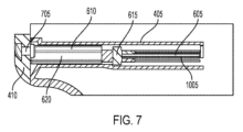
図7は、挿入可能なワイヤレス通信デバイス610がコンパートメント405内に挿入された、コンパートメント405の横切断図である。図7は、カバー410によって覆われたコンパートメント405も示す。図7に示されるように、カバー410は、コンパートメント405の外側からの破片からコンパートメント405を密封するために、本体202の後側に1つ又は複数の留め具705で固定され得る。また、図7に示されるように、第1のPCB605及び挿入可能なワイヤレス通信デバイス610は、略同一平面に広がる。したがって、第1のPCB605及び第2のPCB805(図8及び図9に示されるような挿入可能なワイヤレス通信デバイスのハウジング910に含まれる)は、略同一平面に広がり、PCB605及び805の上面及び底面は、互いに平行に広がる。そのような構成では、第1のPCB605の導電層1005(図10を参照)は、略同一平面に広がり、第2のPCB805の導電層に平行に広がる。以下でより詳細に説明されるように、そのような構成は、PCB605及び805の1つ又は両方が、個別に又は組み合わせて、挿入可能なワイヤレス通信デバイス610上に含まれるアンテナ(例えば、図13及び図14Aに示されるアンテナ1315)の接地面の役割をすることを可能にする。 FIG. 7 is a cross-sectional view of compartment 405 with insertable wireless communication device 610 inserted therein. FIG. 7 also shows compartment 405 covered by cover 410. As shown in FIG. 7, cover 410 may be secured to the rear side of body 202 with one or more fasteners 705 to seal compartment 405 from debris from outside of compartment 405. Also, as shown in FIG. 7, the first PCB 605 and the insertable wireless communication device 610 are substantially coplanar. Accordingly, the first PCB 605 and the second PCB 805 (included in the insertable wireless communication device housing 910 as shown in FIGS. 8 and 9) are substantially coplanar, with the top and bottom surfaces of the PCBs 605 and 805 extend parallel to each other. In such a configuration, the conductive layer 1005 (see FIG. 10) of the first PCB 605 extends substantially coplanar and parallel to the conductive layer of the second PCB 805. As will be explained in more detail below, such a configuration may include an antenna included on an insertable wireless communication device 610 (e.g., FIG. and antenna 1315 shown in FIG. 14A).

図8は、第1のPCB605に電気的且つ物理的に連結された挿入可能なワイヤレス通信デバイス610の斜視図である。図8に示されるように、挿入可能なワイヤレス通信デバイス610は、挿入可能なワイヤレス通信デバイス610のハウジング910内に第2のPCB805(即ち、挿入可能デバイスPCB)を含む。いくつかの実施形態では、第2のPCB805のアンテナ領域810は、アンテナ(例えばチップアンテナなど、図13及び図14Aに示されるアンテナ1315)のために確保されている。 FIG. 8 is a perspective view of an insertable wireless communication device 610 electrically and physically coupled to a first PCB 605. As shown in FIG. 8, insertable wireless communication device 610 includes a second PCB 805 (i.e., an insertable device PCB) within housing 910 of insertable wireless communication device 610. As shown in FIG. In some embodiments, the antenna area 810 of the second PCB 805 is reserved for an antenna (eg, antenna 1315 shown in FIGS. 13 and 14A, such as a chip antenna).

図9は、第1のPCB605から分離された挿入可能なワイヤレス通信デバイス610の斜視図である。図9に示されるように、挿入可能なワイヤレス通信デバイス610の第2のPCB805は、電気的且つ物理的に第1のPCB605の第1のコネクタ615に連結するように構成される第2のコネクタ905(即ち、挿入可能デバイスコネクタ)を含む。 FIG. 9 is a perspective view of insertable wireless communication device 610 separated from first PCB 605. FIG. As shown in FIG. 9, the second PCB 805 of the insertable wireless communication device 610 includes a second connector configured to electrically and physically couple to the first connector 615 of the first PCB 605. 905 (i.e., an insertable device connector).

図10は、第1のPCB605及び第1のコネクタ615の斜視図である。図10に示されるように、第1のPCB605は、第1のPCB605の表面領域全体を通して広がる導電層1005(例えば、銅の層)を含み得る。いくつかの実施形態では、第1のPCB605は、第1のPCB605の上面と底面との間に挟まれる複数のそのような導電層を有し得る。追加的に、いくつかの実施形態では、挿入可能なワイヤレス通信デバイス610の第2のPCB805は、第1のPCB605の導電層1005に類似の1つ又は複数の導電層を含み得る。第1のコネクタ615及び第2のコネクタ905が、それぞれ雌コネクタ及び雄コネクタとして示されているが、いくつかの実施形態では、第1のコネクタ615が、雄コネクタであり、且つ第2のコネクタ905が、雌コネクタであり、又は他の種類のコネクタが用いられる。いくつかの実施形態では、コネクタ615及び905が、含まれなくてもよい。そのような実施形態では、挿入可能なワイヤレス通信デバイス610がコンパートメント405内に挿入されているときに、第1のPCB605のコンポーネントが、第2のPCB805のコンポーネントとワイヤレス通信するように構成され得る。例えば、そのようなワイヤレス通信は、Bluetooth(登録商標)、近距離通信などにより通信するように構成される送受信機/アンテナを介して発生し得る。 FIG. 10 is a perspective view of the first PCB 605 and the first connector 615. As shown in FIG. 10, the first PCB 605 may include a conductive layer 1005 (eg, a layer of copper) that extends throughout the surface area of the first PCB 605. In some embodiments, the first PCB 605 may have a plurality of such conductive layers sandwiched between the top and bottom surfaces of the first PCB 605. Additionally, in some embodiments, the second PCB 805 of the insertable wireless communication device 610 may include one or more conductive layers similar to the conductive layer 1005 of the first PCB 605. Although first connector 615 and second connector 905 are shown as female and male connectors, respectively, in some embodiments first connector 615 is a male connector and second connector 905 is a female connector, or other types of connectors may be used. In some embodiments, connectors 615 and 905 may not be included. In such embodiments, components of the first PCB 605 may be configured to wirelessly communicate with components of the second PCB 805 when the insertable wireless communication device 610 is inserted into the compartment 405. For example, such wireless communication may occur via a transceiver/antenna configured to communicate via Bluetooth, near field communication, or the like.

本明細書で前述したように、コンパートメント405は、電動工具デバイス104の製造後、挿入可能なワイヤレス通信デバイス610が、任意選択でアクセサリとして電動工具デバイス104に追加されることを可能にする。挿入可能なワイヤレス通信デバイス610がコンパートメント405内に挿入されているときに、電動工具デバイス104は、外部デバイス108及び/又はサーバ112などの他のデバイスとワイヤレス通信し得る。いくつかの実施形態では、挿入可能なワイヤレス通信デバイス610がコンパートメント405内に挿入されない限り、電動工具デバイス104は、他のデバイスと(例えば、ワイヤレスで)通信することができないことがある。他の実施形態では、挿入可能なワイヤレス通信デバイス610がコンパートメント405内に挿入されていないときに、電動工具デバイス104は、第1の通信プロトコル(例えば、Bluetooth(登録商標)などの短距離無線通信)を用いて他のデバイスとワイヤレス通信するように構成され得る。そのような実施形態では、挿入可能なワイヤレス通信デバイス610は、コンパートメント405内に挿入されると、追加的又は代替的に、電動工具デバイス104が第1の通信プロトコルとは異なる第2の通信プロトコルを用いて他のデバイスとワイヤレス通信(例えば、セルラーネットワークを経たセルラー通信などの長距離無線通信)することを可能にし得る。その結果、挿入可能なワイヤレス通信デバイス610は、電動工具デバイス104の通信ケイパビリティを拡大するように構成される。 As previously described herein, compartment 405 allows insertable wireless communication device 610 to be optionally added as an accessory to power tool device 104 after manufacture of power tool device 104 . When insertable wireless communication device 610 is inserted into compartment 405, power tool device 104 may wirelessly communicate with other devices, such as external device 108 and/or server 112. In some embodiments, power tool device 104 may not be able to communicate (eg, wirelessly) with other devices unless insertable wireless communication device 610 is inserted into compartment 405. In other embodiments, when the insertable wireless communication device 610 is not inserted into the compartment 405, the power tool device 104 communicates with the first communication protocol (e.g., short-range wireless communication, such as Bluetooth). ) to wirelessly communicate with other devices. In such embodiments, insertable wireless communication device 610, when inserted into compartment 405, additionally or alternatively allows power tool device 104 to communicate with a second communication protocol different from the first communication protocol. may be used to enable wireless communications (e.g., long-range wireless communications, such as cellular communications over a cellular network) with other devices. As a result, insertable wireless communication device 610 is configured to expand the communication capabilities of power tool device 104.

図17~23は、挿入可能なワイヤレス通信デバイス及び挿入可能なワイヤレス通信デバイスを受け入れるように構成されたホストデバイスのコンパートメントの別の実施形態を示す。図17に示されるように、電動工具1705(即ち、ホストデバイス)は、図3の電動工具104と同一のコンポーネントの多くを含む。図3の電動工具104のコンポーネントの本明細書における説明は、以下で説明される差異を除いて電動工具1705の類似名称のコンポーネントに適用される。挿入可能なワイヤレス通信デバイス1905は、挿入可能なワイヤレス通信デバイス610と同一のコンポーネントの多くを含む。挿入可能なワイヤレス通信デバイス610のコンポーネントの本明細書における説明も、以下で説明される差異を除いて挿入可能なワイヤレス通信デバイス1905の類似名称のコンポーネントに適用される。図17に示される電動工具1705は、クリンパーであるが、本明細書で説明される実施形態は、図3の電動工具104に関連して上述したものと同様に、電動工具及び/又はアクセサリを含む多様な電動工具デバイス104及び送信デバイス106(即ち、ホストデバイス)に同様に適用され、併せて使用され得る。 17-23 illustrate another embodiment of an insertable wireless communication device and a compartment of a host device configured to receive the insertable wireless communication device. As shown in FIG. 17, power tool 1705 (ie, host device) includes many of the same components as power tool 104 of FIG. The description herein of the components of power tool 104 of FIG. 3 applies to similarly named components of power tool 1705 except for the differences described below. Insertable wireless communication device 1905 includes many of the same components as insertable wireless communication device 610. The description herein of the components of insertable wireless communication device 610 also applies to similarly named components of insertable wireless communication device 1905, except for the differences described below. Although the power tool 1705 shown in FIG. 17 is a crimper, embodiments described herein may be used to implement power tools and/or accessories similar to those described above in connection with the power tool 104 of FIG. The present invention may similarly be applied to and used in conjunction with a variety of power tool devices 104 and transmitting devices 106 (i.e., host devices) including the present invention.

図17に示されるように、クリンパー1705は、本体1710(即ち、モータハウジング部)、ハンドル部1715、バッテリパック受け部1720、出力駆動デバイス又は機構1725、及び1つ又は複数のトリガ1730(又は他のアクチュエータ)を含む。図17には示されないが、クリンパー1705は、上述のように電動工具104の選択スイッチ208に類似の選択スイッチを含み得る。クリンパー1705は、ハウジングの本体1710内にあり、且つロータ280及びステータ285(図11を参照)を有するモータ214(図11を参照)をさらに含む。クリンパー1705のハウジング(例えば、本体1710、ハンドル1715、及びバッテリパック受け部1720)は、耐久性のある軽量プラスチック材から構成される。クリンパー1705上の駆動デバイス1725は、圧着ジョーのセットである。しかしながら、異なる電動工具デバイスは、本明細書で前述したように電動工具デバイスに関連付けられたタスクのために具体的に設計された異なる駆動デバイスを有し得る。図17に示されるように、クリンパー1705は、以下でさらに詳細に説明されるように、挿入可能なワイヤレス通信デバイス1905を受け入れるように構成されたコンパートメント1910(図19を参照)を覆うように構成されたカバー1735を含む。 As shown in FIG. 17, the crimper 1705 includes a body 1710 (i.e., a motor housing portion), a handle portion 1715, a battery pack receiver 1720, an output drive device or mechanism 1725, and one or more triggers 1730 (or other actuator). Although not shown in FIG. 17, crimper 1705 may include a selection switch similar to selection switch 208 of power tool 104, as described above. The crimper 1705 further includes a motor 214 (see FIG. 11) within the body 1710 of the housing and having a rotor 280 and a stator 285 (see FIG. 11). The housing of crimper 1705 (eg, body 1710, handle 1715, and battery pack receiver 1720) is constructed from a durable, lightweight plastic material. Drive device 1725 on crimper 1705 is a set of crimping jaws. However, different power tool devices may have different drive devices specifically designed for the tasks associated with the power tool device as previously described herein. As shown in FIG. 17, the crimper 1705 is configured to cover a compartment 1910 (see FIG. 19) that is configured to receive an insertable wireless communication device 1905, as described in further detail below. 1735.

図18は、挿入可能なワイヤレス通信デバイス1905を受け入れるように構成されたコンパートメント1910を覆うように構成されたカバー1810を含む別のホストデバイス1805(例えば、電動工具)を示す。図18に示されるように、電動工具1805は、図3の電動工具104及び図17の電動工具1705とは異なる種類の電動工具であり、(例えば、電動工具1805のハンドル部1815及び本体部(図示せず)に接続された電動工具1805の基部の側面上の)電動工具104及び1705とは異なる位置にコンパートメント1910及びカバー1810を含む。 FIG. 18 shows another host device 1805 (eg, a power tool) that includes a cover 1810 configured to cover a compartment 1910 configured to receive an insertable wireless communication device 1905. As shown in FIG. 18, the power tool 1805 is a different type of power tool from the power tool 104 in FIG. 3 and the power tool 1705 in FIG. The power tool 1805 includes a compartment 1910 and a cover 1810 in a different location than the power tools 104 and 1705 (on the side of the base of the power tool 1805 connected to the power tool 1805).

図19は、挿入可能なワイヤレス通信デバイス1905(即ち、挿入可能デバイス)を受け入れるように構成されたコンパートメント1910を含む、クリンパー1705の本体1710の一部の斜視切断図である。図19に示されるように、本体1710のハウジングは、コンパートメント1910内に封入容器1920を保持するように構成された様々な取り付け部1915を含む。コンパートメント1910は、クリンパー1705の本体1710の下部(例えば、ハンドル1715の上且つモータの下又は本体1710の埋め込みボート1925に位置する電源/FET PCBの下の平面上)に位置するが、他の実施形態又は他のホストデバイスにおいては、コンパートメント1910は、本明細書で前述された他の位置に位置し得る(例えば、図18を参照)。 FIG. 19 is a perspective cutaway view of a portion of the body 1710 of the crimper 1705, including a compartment 1910 configured to receive an insertable wireless communication device 1905 (ie, an insertable device). As shown in FIG. 19, the housing of body 1710 includes various attachments 1915 configured to retain an enclosure 1920 within compartment 1910. The compartment 1910 is located at the bottom of the body 1710 of the crimper 1705 (e.g., on a plane above the handle 1715 and below the motor or below the power supply/FET PCB located in the recessed boat 1925 of the body 1710), but other implementations are possible. In other embodiments or other host devices, the compartment 1910 may be located in other locations as previously described herein (see, eg, FIG. 18).

図20A~20Dは、封入容器1920の種々の図を示す。図20Aは、封入容器1920の内側に収容されたコンポーネントを視認できるようにするために封入容器1920の壁が透明であるように示される、封入容器1920の下部斜視図である。図20Bは、封入容器1920及び封入容器1920の内側に収容されるコンポーネントの下部斜視分解図である。図20Cは、封入容器がワイヤ開口部2003を含む、封入容器1920の上部斜視図である。図20Dは、封入容器1920の内側に収容されたコンポーネントを視認できるようにするために封入容器1920の壁が透明であるように示される、封入容器1920の側面図である。図20A、図20C、及び図20Dに示されるように、挿入可能なワイヤレス通信デバイス1905は、封入容器1920内に挿入される。 20A-20D show various views of the enclosure 1920. FIG. 20A is a bottom perspective view of the enclosure 1920 in which the walls of the enclosure 1920 are shown to be transparent to allow viewing of the components housed inside the enclosure 1920. FIG. 20B is a bottom perspective exploded view of the enclosure 1920 and the components contained within the enclosure 1920. FIG. 20C is a top perspective view of the enclosure 1920, where the enclosure includes a wire opening 2003. FIG. 20D is a side view of the enclosure 1920 in which the walls of the enclosure 1920 are shown to be transparent to allow viewing of the components housed inside the enclosure 1920. As shown in FIGS. 20A, 20C, and 20D, insertable wireless communication device 1905 is inserted into enclosure 1920.

封入容器1920がクリンパー1705に設置されるとき、封入容器1920の外側端2005は、挿入可能なワイヤレス通信デバイス1905を受け入れるように構成される。外側端2005の反対側の封入容器1920の内側端2010は、クリンパー1705の製造中にホスト側PCB2015を受け入れるように構成される。ホスト側PCB2015は、本明細書で前述した電動工具104の第1のPCB605に類似している。第1のPCB605に関して本明細書で前述した詳細は、ホスト側PCB2015にも適用される。例えば、ホスト側PCB2015は、(挿入可能なワイヤレス通信デバイス610の第2のコネクタ905に類似の)挿入可能なワイヤレス通信デバイス1905の挿入可能デバイスコネクタ2025に(物理的に、電気的に、又はその両方で)連結するように構成される、(第1のPCB605の第1のコネクタ615に類似の)ホスト側コネクタ2020を含む。いくつかの実施形態では、コネクタ2020及び2025が含まれなくてもよく、挿入可能なワイヤレス通信デバイス1905が封入容器1920に挿入されているとき、ホスト側PCB2015のコンポーネントは、挿入可能なワイヤレス通信デバイス1905とワイヤレス通信するように構成され得る。ホスト側PCB2015が封入容器1920に設置された後、封入容器1920の内側端2010は、ワイヤキャップ2030によって密封される。ワイヤキャップ2030は、クリンパー1705のハウジング内側からの破片が封入容器1920に入ることを防止し得る。いくつかの実施形態では、封入容器1920は、図5Aの取り付け部510に類似の取り付け部を含む。封入容器1920は、ホスト側PCB2015及び/又は挿入可能なワイヤレス通信デバイス1905の挿入可能デバイスPCB2035を保持するように構成されたチャネルを含む、取り付け部を含み得る。 When enclosure 1920 is installed in crimper 1705, outer end 2005 of enclosure 1920 is configured to receive insertable wireless communication device 1905. An inner end 2010 of the enclosure 1920 opposite the outer end 2005 is configured to receive a host PCB 2015 during manufacture of the crimper 1705. Host side PCB 2015 is similar to first PCB 605 of power tool 104 previously described herein. Details described herein above with respect to first PCB 605 also apply to host side PCB 2015. For example, host PCB 2015 connects (physically, electrically, or a host-side connector 2020 (similar to first connector 615 of first PCB 605) configured to couple (on both); In some embodiments, connectors 2020 and 2025 may not be included, and when the insertable wireless communication device 1905 is inserted into the enclosure 1920, the components of the host PCB 2015 may not include the insertable wireless communication device. 1905 . After the host PCB 2015 is installed in the enclosure 1920, the inner end 2010 of the enclosure 1920 is sealed by a wire cap 2030. Wire cap 2030 may prevent debris from inside the housing of crimper 1705 from entering enclosure 1920. In some embodiments, enclosure 1920 includes a fitting similar to fitting 510 of FIG. 5A. Enclosure 1920 may include a mount that includes a channel configured to hold host PCB 2015 and/or insertable device PCB 2035 of insertable wireless communication device 1905.

図20Cに示されるワイヤ開口部2003は、ワイヤが封入容器1920から出ること及びクリンパー1705のハウジング内側の他の電気コンポーネント(例えば、クリンパー1705のモータ214を制御するように構成された電子プロセッサ226、コイン形を含む電動工具バッテリパック又はエネルギー貯蔵デバイスなどの電源など)に接続されることを可能にする。いくつかの実施形態では、ワイヤ開口部2003は、封入容器1920の内側端2010の開口部よりも小さい。したがって、ホスト側PCB2015に接続されるワイヤは、内側端2010の開口部から出てルーティングされるのではなく、ワイヤ開口部2003を通ってルーティングされ得る。内側端2010の開口部は、その代わりにワイヤキャップ2030で密封されて、封入容器の内側端2010の開口部を通してワイヤを延ばすのと比較して進入流体防止が向上し得る。いくつかの実施形態では、ワイヤをワイヤ開口部2003からルーティングすることによって、ワイヤが封入容器1920の内側端2010の開口部からルーティングされるときよりも封入容器アセンブリの長さが短くなるため、クリンパー1705内の空間が節約される。それにも関わらず、いくつかの実施形態では、1つ又は複数のワイヤが、封入容器1920の内側端2010の開口部からルーティングされてもよい。 The wire opening 2003 shown in FIG. 20C allows the wire to exit the enclosure 1920 and other electrical components inside the housing of the crimper 1705 (e.g., an electronic processor 226 configured to control the motor 214 of the crimper 1705). power tools, including coin-shaped power tools (such as battery packs or energy storage devices). In some embodiments, the wire opening 2003 is smaller than the opening in the inner end 2010 of the enclosure 1920. Accordingly, wires connected to the host side PCB 2015 may be routed through the wire opening 2003 rather than being routed out of the opening in the inner end 2010. The opening in the inner end 2010 may instead be sealed with a wire cap 2030 to improve ingress fluid prevention compared to extending a wire through the opening in the inner end 2010 of the enclosure. In some embodiments, routing the wire through the wire opening 2003 results in a shorter length of the enclosure assembly than when the wire is routed through the opening in the inner end 2010 of the enclosure 1920, so the crimper Space within 1705 is saved. Nevertheless, in some embodiments, one or more wires may be routed from an opening in the inner end 2010 of the enclosure 1920.

図20Dに示されるように、ホスト側PCB2015及び挿入可能デバイスPCB2035は、本明細書で前述したように、電動工具104の第1のPCB605及び第2のPCB805と同様に略同一平面に広がる(図7を参照)。このような構成では、ホスト側PCB2015の導電層2040は、略同一平面に広がり、且つ挿入可能デバイスPCB2035の導電層2045に平行に広がり得る。以下でより詳細に説明されるように、このような構成は、PCB2015及び2035の1つ又は両方が、個別に又は組み合わせて、挿入可能なワイヤレス通信デバイス1905上に含まれるアンテナ(例えば、図20D、図21、及び図23に示されるチップアンテナ/導体2105を含むアンテナ1315)の接地面の役割をすることを可能にする。 As shown in FIG. 20D, the host-side PCB 2015 and the insertable device PCB 2035 extend substantially coplanar (see FIG. 7). In such a configuration, the conductive layer 2040 of the host side PCB 2015 may extend substantially coplanar and parallel to the conductive layer 2045 of the insertable device PCB 2035. As will be explained in more detail below, such a configuration allows one or both of PCBs 2015 and 2035, individually or in combination, to include an antenna (e.g. , FIG. 21, and FIG. 23).

図20E及び図20Fは、一実施形態による、封入容器1920の種々の下部斜視図を示す。図20E及び図20Fにおいて、封入容器1920の壁は、以下で説明される封入容器1920の内部特徴を視認できるようにするために、透明であるように示される。図20E及び図20Fに示されるように、封入容器1920は、封入容器1920の側壁上に位置し、PCB2015及び2035の縁を受け入れ、且つ導くように構成される、1つ又は複数のチャネル2050を含み得る。チャネル2050は、製造中にホスト側PCB2015が封入容器1920内に過度に挿入されることを防止し、且つ/又は挿入可能なワイヤレス通信デバイス1905がユーザによって封入容器1920内に過度に挿入されることを防止する、末端壁2055を含み得る。 20E and 20F illustrate various bottom perspective views of an enclosure 1920, according to one embodiment. In FIGS. 20E and 20F, the walls of enclosure 1920 are shown to be transparent to allow viewing of internal features of enclosure 1920, which will be described below. As shown in FIGS. 20E and 20F, the enclosure 1920 has one or more channels 2050 located on the sidewalls of the enclosure 1920 and configured to receive and guide the edges of the PCBs 2015 and 2035. may be included. Channel 2050 prevents host PCB 2015 from being over-inserted into enclosure 1920 during manufacturing and/or prevents insertable wireless communication device 1905 from being over-inserted into enclosure 1920 by a user. may include an end wall 2055 that prevents.

図21は、ホスト側PCB2015に電気的且つ物理的に連結された挿入可能なワイヤレス通信デバイス1905の下部斜視図である。図22は、一例としての実施形態による、挿入可能なワイヤレス通信デバイス1905の部分分解下部斜視図である。いくつかの実施形態では、挿入可能なワイヤレス通信デバイス1905が封入容器1920内に挿入されているときに、挿入可能デバイスPCB2035は、封入容器1920の外側端2005付近に位置するチップアンテナ2105(即ち、アンテナ1315の導体部)を含む。図21に示されるように、挿入可能デバイスPCB2035は、他の電子部品も含む。例えば、挿入可能デバイスPCB2035は、図14A~図14Jに示されるように、Bluetooth(登録商標)送受信機/コントローラ、アンテナ1315又は別のアンテナを介したワイヤレス通信を可能にするように構成された他の電子プロセッサ/集積回路などを含み得る。図21は、PCB2015及び2035の底面に取り付けられたコンポーネントを示しているが、いくつかの実施形態では、コンポーネントは、PCB2015及び2035の上面に追加的又は代替的に取り付けられてもよい。 FIG. 21 is a bottom perspective view of insertable wireless communication device 1905 electrically and physically coupled to host PCB 2015. FIG. 22 is a partially exploded bottom perspective view of an insertable wireless communication device 1905, according to an example embodiment. In some embodiments, when the insertable wireless communication device 1905 is inserted into the enclosure 1920, the insertable device PCB 2035 is connected to the chip antenna 2105 located near the outer end 2005 of the enclosure 1920 (i.e., (conductor portion of antenna 1315). As shown in FIG. 21, insertable device PCB 2035 also includes other electronic components. For example, insertable device PCB 2035 may be a Bluetooth transceiver/controller, antenna 1315, or another device configured to enable wireless communication via another antenna, as shown in FIGS. 14A-14J. electronic processors/integrated circuits, etc. Although FIG. 21 shows components attached to the bottom surfaces of PCBs 2015 and 2035, in some embodiments components may additionally or alternatively be attached to the top surfaces of PCBs 2015 and 2035.

図21は、アンテナ1315の接地面2107の例としての寸法についてのラベルを含む。例えば、ホスト側PCB2015は、約34ミリメートル長であってもよく、ホスト側PCB2015の導電層2040は、アンテナ1315のための接地面2107の一部を形成してもよい。同様に、約41ミリメートルの挿入可能デバイスPCB2035の導電層2045が、アンテナ1315のための接地面2107の残りを形成するために使用され得る。いくつかの実施形態では、挿入可能デバイスPCB2035は、約41ミリメートルよりも長く、挿入可能デバイスPCB2035の一部(例えば、封入容器1920の外側端2005に近位の部分)は、アンテナ1315のための接地面2107の一部として使用されない。 FIG. 21 includes a label for example dimensions of the ground plane 2107 of the antenna 1315. For example, the host-side PCB 2015 may be approximately 34 millimeters long, and the conductive layer 2040 of the host-side PCB 2015 may form part of the ground plane 2107 for the antenna 1315. Similarly, approximately 41 millimeters of conductive layer 2045 of insertable device PCB 2035 may be used to form the remainder of ground plane 2107 for antenna 1315. In some embodiments, the insertable device PCB 2035 is longer than about 41 millimeters, and a portion of the insertable device PCB 2035 (e.g., a portion proximal to the outer end 2005 of the enclosure 1920) has a length for the antenna 1315. Not used as part of ground plane 2107.

いくつかの実施形態では、挿入可能なワイヤレス通信デバイス1905が封入容器1920内に挿入されているとき、挿入可能なワイヤレス通信デバイス1905は、封入容器1920の外側端2005付近に位置する端部キャップ2110を含む。いくつかの実施形態では、挿入可能なワイヤレス通信デバイス1905が封入容器1920内に挿入されているとき、端部キャップ2110の外側面は、挿入可能なワイヤレス通信デバイス1905が受け入れられる封入容器1920の開口部と略同一面に位置する(図20Dを参照)。いくつかの実施形態では、端部キャップ2110は、挿入可能なワイヤレス通信デバイス1905が、例えばユーザによって落下される状況においてチップアンテナ2105を保護するために、チップアンテナ2105に近接して位置する。図20D及び図21に示されるように、挿入可能デバイスPCB2035の表面に垂直な方向の端部キャップ2110の高さは、挿入可能デバイスPCB2035の表面に垂直な方向のチップアンテナ2105の高さより高い。同様に、挿入可能デバイスPCB2035の表面に垂直な方向のコネクタ2025の高さは、挿入可能デバイスPCB2035の表面に垂直な方向のチップアンテナ2105の高さより高い。したがって、挿入可能なワイヤレス通信デバイス1905がユーザによって落下される場合、チップアンテナ2105は、平坦面との衝突時の挿入可能デバイス1905の向きに関わらず、挿入可能デバイス1905が着地する略平坦面(例えば、床)に直接衝撃を与えるべきではない。むしろ、挿入可能なワイヤレス通信デバイス1905が落下された場合、挿入可能デバイスPCB2035の上側、挿入可能デバイスPCB2035の辺/縁、コネクタ2025、又は端部キャップ2110のうちの1つが、平坦面に衝撃を与える。 In some embodiments, when the insertable wireless communication device 1905 is inserted into the enclosure 1920, the insertable wireless communication device 1905 is attached to the end cap 2110 located near the outer end 2005 of the enclosure 1920. including. In some embodiments, when the insertable wireless communication device 1905 is inserted into the enclosure 1920, the outer surface of the end cap 2110 forms an opening in the enclosure 1920 in which the insertable wireless communication device 1905 is received. (See FIG. 20D). In some embodiments, end cap 2110 is positioned proximate chip antenna 2105 to protect chip antenna 2105 in situations where insertable wireless communication device 1905 is dropped, such as by a user. As shown in FIGS. 20D and 21, the height of end cap 2110 in a direction normal to the surface of insertable device PCB 2035 is greater than the height of chip antenna 2105 in a direction normal to the surface of insertable device PCB 2035. Similarly, the height of connector 2025 in a direction normal to the surface of insertable device PCB 2035 is greater than the height of chip antenna 2105 in a direction normal to the surface of insertable device PCB 2035. Therefore, if the insertable wireless communication device 1905 is dropped by the user, the chip antenna 2105 will be placed on the generally flat surface on which the insertable device 1905 lands ( For example, direct impact should not be applied to the floor). Rather, if the insertable wireless communication device 1905 is dropped, one of the top side of the insertable device PCB 2035, the edge/edge of the insertable device PCB 2035, the connector 2025, or the end cap 2110 will impact the flat surface. give.

図22に示されるように、端部キャップ2110は、挿入可能デバイスPCB2035の穴を通って互いに連結して端部キャップ2110を形成するように構成される、上部2115a及び下部2115bを含み得る。いくつかの実施形態では、端部キャップ2110の高さは、挿入可能デバイスPCB2035とクリンパー1705の他のコンポーネントとの間にある量の間隔を与えるように設計される。言い換えると、端部キャップ2110は、端部キャップ2110の高さが、例えば、挿入可能デバイスPCB2035とクリンパー1705に接続された電動工具バッテリパックの電極との間に最小限必要な量の空間(例えば、5ミリメートル)を与えるようなサイズにされ得る。端部キャップ2110は、端部キャップ2110が存在しない場合よりも容易に(例えば、挿入可能デバイス1905を挿入又は除去するときに)挿入可能なワイヤレス通信デバイス1905をユーザが掴むことも可能にし得る。端部キャップ2110は、また、挿入可能デバイス1905を挿入又は除去するときに、ユーザが、例えば指や他の物体をコンパートメント1910に挟むか又は挿入することを防止し得る。 As shown in FIG. 22, the end cap 2110 may include an upper portion 2115a and a lower portion 2115b configured to couple together through a hole in the insertable device PCB 2035 to form the end cap 2110. In some embodiments, the height of end cap 2110 is designed to provide an amount of spacing between insertable device PCB 2035 and other components of crimper 1705. In other words, the end cap 2110 is configured such that the height of the end cap 2110 is such that, for example, the height of the end cap 2110 is such that a minimum required amount of space (e.g. , 5 mm). End cap 2110 may also allow a user to grasp insertable wireless communication device 1905 more easily (eg, when inserting or removing insertable device 1905) than if end cap 2110 were not present. End cap 2110 may also prevent a user from pinching or inserting, for example, a finger or other object into compartment 1910 when inserting or removing insertable device 1905.

いくつかの実施形態では、挿入可能デバイスPCB2035は、端部キャップ2110を通って延びるように構成された突出タブ2120を含む。いくつかの実施形態では、突出タブ2120は、封入容器1920から延びるように構成される(図20A、図20C、及び図20Dを参照)。突出タブ2120は、挿入可能なワイヤレス通信デバイス1905を封入容器1920から除去するために使用されるように構成され得る。突出タブ2120は、図22では概して長方形を有するが、いくつかの実施形態では、突出タブ2120は、丸みがつけられた角を有するか、又は部分的に円形又は部分的に楕円の形状であるように丸みが付けられている。いくつかの実施形態では、突出タブ2120の縁は面取りされている。いくつかの実施形態では、挿入可能なワイヤレス通信デバイス1905を封入容器1920から除去するためにユーザによって把持され引っ張られるように、リボン、テープ、又はロープ(例えば、ナイロンロープ)が突出タブ2120に接続される。 In some embodiments, insertable device PCB 2035 includes a protruding tab 2120 configured to extend through end cap 2110. In some embodiments, the protruding tab 2120 is configured to extend from the enclosure 1920 (see FIGS. 20A, 20C, and 20D). Projecting tab 2120 may be configured to be used to remove insertable wireless communication device 1905 from enclosure 1920. Although the protruding tab 2120 has a generally rectangular shape in FIG. 22, in some embodiments the protruding tab 2120 has rounded corners or is partially circular or partially oval in shape. It is rounded like this. In some embodiments, the edges of the protruding tabs 2120 are chamfered. In some embodiments, a ribbon, tape, or rope (e.g., a nylon rope) is connected to the protruding tab 2120 so that it can be grasped and pulled by a user to remove the insertable wireless communication device 1905 from the enclosure 1920. be done.

図19、図20B、及び図22に示されるように、挿入可能デバイスPCB2035のいくつかの部分が、挿入可能デバイスPCB2035上に取り付けられた少なくともいくつかのコンポーネントの上に低圧成形2205(例えば、プラスチック成形)を含み得る。例えば、低圧成形2205は、挿入可能デバイスPCB2035の底面上の全てのコンポーネントの上に位置し得る。低圧成形は、挿入可能デバイスPCB2035の上面の周囲に巻かれ、挿入可能デバイスPCB2035の底面上よりも少ない、挿入可能デバイスPCB2035の上面の面積又はコンポーネントを覆い得る(図19を参照)。図19、図20B、図22に示されるように、低圧成形2205は、挿入可能デバイスPCB2035を完全に封入しなくてもよい。例えば、挿入可能デバイスPCB2035の側縁は露出したままであってもよく、低圧成形2205から突出してもよい。いくつかの実施形態では、挿入可能なワイヤレス通信デバイス1905が封入容器1920内に挿入されるとき、挿入可能デバイスPCB2035のこれらの側縁が、封入容器1920の取り付け部(例えば、チャネル)と係合する。いくつかの実施形態では、挿入可能なワイヤレス通信デバイス1905が封入容器1920内に挿入されていない(例えば、挿入可能デバイスPCB2035の側縁が露出している)ときに、挿入可能なワイヤレス通信デバイス1905が、挿入可能デバイスPCB2035を完全に封入するように構成された外部ハウジングを含まないため、挿入可能なワイヤレス通信デバイス1905は、ハウジングなし挿入可能デバイス1905と呼ばれ得る。ハウジングなし挿入可能デバイス1905によって、挿入可能なワイヤレス通信デバイス1905は、外部ハウジングを含む他の挿入可能デバイス(例えば、図6~図9に示されるような外部ハウジング910を有する挿入可能デバイス610)よりもコンパクトであることが可能となる。したがって、ハウジングなしの挿入可能なワイヤレス通信デバイス1905は、それが挿入されるように構成されるホストデバイス1705に少ない空間しか取らなくてもよい。いくつかの実施形態では、低圧成形2205は、挿入可能デバイスPCB2035の、より多くのコンポーネント又はより少ないコンポーネントを覆い得る。いくつかの実施形態では、低圧成形2205が存在しなくてもよい。 As shown in FIGS. 19, 20B, and 22, portions of the insertable device PCB 2035 are low-pressure molded 2205 (e.g., plastic) over at least some components mounted on the insertable device PCB 2035. molding). For example, low pressure molding 2205 may be located over all components on the bottom of insertable device PCB 2035. The low pressure molding may be wrapped around the top surface of the insertable device PCB 2035 and cover less area or components of the top surface of the insertable device PCB 2035 than on the bottom surface of the insertable device PCB 2035 (see FIG. 19). As shown in FIGS. 19, 20B, and 22, the low pressure molding 2205 may not completely encapsulate the insertable device PCB 2035. For example, the side edges of insertable device PCB 2035 may remain exposed and may protrude from low pressure molding 2205. In some embodiments, these side edges of the insertable device PCB 2035 engage attachment portions (e.g., channels) of the enclosure 1920 when the insertable wireless communication device 1905 is inserted into the enclosure 1920. do. In some embodiments, when the insertable wireless communication device 1905 is not inserted within the enclosure 1920 (e.g., the side edges of the insertable device PCB 2035 are exposed), the insertable wireless communication device 1905 The insertable wireless communication device 1905 may be referred to as a housingless insertable device 1905 because it does not include an external housing configured to completely enclose the insertable device PCB 2035. Housingless insertable device 1905 allows insertable wireless communication device 1905 to be more easily inserted than other insertable devices that include an external housing (e.g., insertable device 610 with external housing 910 as shown in FIGS. 6-9). can also be compact. Accordingly, the insertable wireless communication device 1905 without a housing may take up less space in the host device 1705 into which it is configured to be inserted. In some embodiments, low pressure molding 2205 may cover more or fewer components of insertable device PCB 2035. In some embodiments, low pressure molding 2205 may not be present.

図23は、一例としての実施形態による、挿入可能なワイヤレス通信デバイス1905の複数面図を示す。図23に示される実施形態では、低圧成形2205は示されていない。図23は、上面図2305、底面図2310、正面図2315(即ち、挿入可能なワイヤレス通信デバイス1905がコンパートメント1910内に挿入されているときのクリンパー1705の正面から)、背面図2320(即ち、挿入可能なワイヤレス通信デバイス1905がコンパートメント1910内に挿入されているときのクリンパー1705の背面から)、右側面図2325(即ち、モータシャフトに沿ってクリンパー1705の正面において見ているときのクリンパー1705の右側面)、及び左側面図2330(即ち、モータシャフトに沿ってクリンパー1705の正面において見ているときのクリンパー1705の左側面)を含む。図23の寸法によって示されるように、いくつかの実施形態では、挿入可能デバイスPCB2035は、突出タブ2120及びコネクタ2025が取り付けられる領域を含んで、約52ミリメートル長である。いくつかの実施形態では、挿入可能デバイスPCB2035は、約35.2ミリメートル幅である。他の実施形態では、挿入可能デバイスPCB2035は、約49.4ミリメートル長及び37.4ミリメートル幅である。図23に示されるように、いくつかの実施形態では、挿入可能なワイヤレス通信デバイス1905の高さは、約7.5ミリメートルである。いくつかの実施形態では、チップアンテナ2105が取り付けられる領域に対向する挿入可能デバイスPCB2035の表面の領域は、チップアンテナ2105の適切な機能を確保するために電気コンポーネントが取り付けられないキープアウト領域2335である。 FIG. 23 illustrates multiple views of an insertable wireless communication device 1905, according to an example embodiment. In the embodiment shown in FIG. 23, low pressure molding 2205 is not shown. FIG. 23 shows a top view 2305, a bottom view 2310, a front view 2315 (i.e., from the front of the crimper 1705 when the insertable wireless communication device 1905 is inserted into the compartment 1910), and a rear view 2320 (i.e., the insertion right side view 2325 (i.e., right side of the crimper 1705 when looking at the front of the crimper 1705 along the motor shaft); 2330 (i.e., the left side of the crimper 1705 when looking in front of the crimper 1705 along the motor shaft). As shown by the dimensions in FIG. 23, in some embodiments, insertable device PCB 2035 is approximately 52 millimeters long, including the area where protruding tabs 2120 and connectors 2025 are attached. In some embodiments, insertable device PCB 2035 is approximately 35.2 millimeters wide. In other embodiments, insertable device PCB 2035 is approximately 49.4 millimeters long and 37.4 millimeters wide. As shown in FIG. 23, in some embodiments, the height of insertable wireless communication device 1905 is approximately 7.5 millimeters. In some embodiments, the area of the surface of the insertable device PCB 2035 opposite the area where the chip antenna 2105 is attached is a keep-out area 2335 where no electrical components are attached to ensure proper functioning of the chip antenna 2105. be.

図4~図7及び図17~図23に示され、上述された、コンパートメント405、1910の位置及び物理的設計及び挿入可能なワイヤレス通信デバイス610、1905の物理的設計は、実施例であり、他の実施形態において又は異なるホストデバイス上では異なり得る。例えば、コンパートメント405、1910は、モータ214の下且つハンドル204、1715の上の本体202、1710に位置して示され、コンパートメント405、1910は、電動工具104、1705のハウジングの他の部分に位置し得る。例えば、コンパートメント405、1910は、ハンドル204、1715に、バッテリパック受け部206、1720に、若しくはバッテリパック受け部206、1720の真上(即ち、電動工具104、1705の足元)に、又は電動工具104、1705のハウジングの別の部分に、位置し得る。追加的に、コンパートメント405、1910は、図4~図7及び図17及び図19に示される向きとは異なる向きにされてもよい(例えば、図18を参照)。例えば、コンパートメント405、1910の開口部は、本体202、1710の後壁の代わりに本体202、1710の側壁上に位置し得る。本明細書で前に与えられた例としての電動工具104のリストにより示されるように、電動工具デバイス104の種類によっては、電動工具デバイス104のハウジングは、本体202、1710、ハンドル204、1715、及びバッテリパック受け部206、1720のうちの1つ又は複数を含まなくてもよい。挿入可能なワイヤレス通信デバイス610、1905が、以下でさらに詳細に説明されるように適切に機能する(例えば、通信に使用されている通信プロトコルについての最小アンテナ効率標準を満たすアンテナを介して外部デバイス108及び/又はサーバ112と通信する)ことができるように、コンパートメント405、1910は、電動工具デバイス104のハウジングの任意の部分において任意の向きで位置してもよい。 The locations and physical designs of compartments 405, 1910 and insertable wireless communication devices 610, 1905 shown in FIGS. 4-7 and 17-23 and described above are examples; It may be different in other embodiments or on different host devices. For example, compartments 405, 1910 are shown located in the body 202, 1710 below the motor 214 and above the handle 204, 1715, and compartments 405, 1910 are shown located in other parts of the housing of the power tool 104, 1705. It is possible. For example, the compartment 405, 1910 may be placed on the handle 204, 1715, on the battery pack receiver 206, 1720, or directly above the battery pack receiver 206, 1720 (i.e., at the foot of the power tool 104, 1705), or 104, 1705 may be located in another portion of the housing. Additionally, the compartments 405, 1910 may be oriented differently than shown in FIGS. 4-7 and 17 and 19 (see, eg, FIG. 18). For example, the opening of the compartment 405, 1910 may be located on the side wall of the body 202, 1710 instead of the rear wall of the body 202, 1710. As illustrated by the list of example power tools 104 given earlier herein, depending on the type of power tool device 104, the housing of the power tool device 104 may include a body 202, 1710, a handle 204, 1715, and battery pack receivers 206, 1720. The insertable wireless communication device 610, 1905 is configured to function properly as described in further detail below (e.g., to communicate with an external device via an antenna that meets minimum antenna efficiency standards for the communication protocol being used to communicate with the external device). 108 and/or server 112), the compartments 405, 1910 may be located in any orientation in any portion of the housing of the power tool device 104.

いくつかの実施形態では、挿入可能なワイヤレス通信デバイス610、1905は、それぞれが同一のコンパートメント405、1910を含み、ハウジングの異なる部分に位置し、且つ各ホストデバイスにおいて異なる向きにされたコンパートメント405、1910を有し得る、複数のホストデバイス(例えば、電動工具デバイス104及び送信デバイス106)のうちのいずれか1つの中に挿入可能であるように構成される。言い換えると、挿入可能なワイヤレス通信デバイス610、1905及びコンパートメント405、1910の物理的設計は、多くの異なるホストデバイスにわたって普遍的であってもよいが、少なくともいくつかのホストデバイスのためのコンパートメント405、1910の位置及び向きは、異なっていてもよい。 In some embodiments, insertable wireless communication devices 610, 1905 each include identical compartments 405, 1910, compartments 405 located in different parts of the housing and oriented differently in each host device; 1910 and is configured to be insertable into any one of a plurality of host devices (eg, power tool device 104 and transmitting device 106). In other words, although the physical design of the insertable wireless communication device 610, 1905 and the compartment 405, 1910 may be universal across many different host devices, the compartment 405 for at least some host devices, The location and orientation of 1910 may vary.

図4~図7及び図17~図19は、コンパートメント405、1910を覆い、密封するための、留め具705によって固定されたカバー410、1735、1810を示しているが、いくつかの実施形態において、コンパートメント405、1910は、カバー410、1735、1810、及び/又は留め具705を含まなくてもよい。例えば、カバー410、1735、1810は、留め具705を用いることを含まない他のやり方で、電動工具104、1705、1805に留められてもよい。例えば、カバー410、1735、1810は、単にコンパートメント405、1910に押圧されてもよく、カバー410、1735、1810とコンパートメント405、1910との間の摩擦によって固定されてもよい。図16A~図16Cは、カバー410、1735、1810の3つの代替実施形態を示す。図16Aは、固定タブ1610を含む、押し込みスナップフィットカバー1605を示す。図16Bは、固定タブ1620を含むスライドスナップフィットカバー1615を示す。図16Cは、ヒンジ付きゴム圧着カバー1625を示す。別の例としての代替実施形態として、電動工具104、1705、1805は、コンパートメント405、1910のためのカバーを含まなくてもよい。その代わりに、挿入可能なワイヤレス通信デバイス610、1905は、コンパートメント405、1910を密封し、破片がコンパートメント405、1910に入ることを防止するように、コンパートメント405、1910内に挿入されるように構成され得る。そのような実施形態では、挿入可能なワイヤレス通信デバイス610、1905の後側(即ち、外側)(即ち、挿入可能デバイス610の外壁625又は挿入可能デバイス1905の端部キャップ2110)は、電動工具104、1705のハウジングと同一面であってもよい。いくつかの実施形態では、電動工具104、1705、1805は、破片からコンパートメント405、1910を密封するためにコンパートメント405、1910に挿入される(いかなる通信機能も有しない)プレースホルダ挿入可能デバイスと共に販売されてもよい。後になって、ユーザが電動工具104、1705、1805の通信ケイパビリティを強化することを望む場合、ユーザは、プレースホルダ挿入可能デバイスを除去し、挿入可能なワイヤレス通信デバイス610、1905をコンパートメント405、1910内に挿入し得る。 4-7 and 17-19 illustrate covers 410, 1735, 1810 secured by fasteners 705 for covering and sealing compartments 405, 1910, but in some embodiments , compartment 405, 1910 may not include cover 410, 1735, 1810, and/or fastener 705. For example, the cover 410, 1735, 1810 may be fastened to the power tool 104, 1705, 1805 in other ways that do not include using the fastener 705. For example, the cover 410, 1735, 1810 may simply be pressed against the compartment 405, 1910, or may be secured by friction between the cover 410, 1735, 1810 and the compartment 405, 1910. 16A-16C illustrate three alternative embodiments of covers 410, 1735, 1810. FIG. 16A shows a push-in snap-fit cover 1605 that includes securing tabs 1610. FIG. 16B shows a sliding snap-fit cover 1615 that includes securing tabs 1620. FIG. 16C shows a hinged rubber crimp cover 1625. As another example and alternative embodiment, the power tool 104, 1705, 1805 may not include a cover for the compartment 405, 1910. Instead, the insertable wireless communication device 610, 1905 is configured to be inserted into the compartment 405, 1910 to seal the compartment 405, 1910 and prevent debris from entering the compartment 405, 1910. can be done. In such embodiments, the rear (i.e., outer side) of the insertable wireless communication device 610 , 1905 (i.e., the outer wall 625 of the insertable device 610 or the end cap 2110 of the insertable device 1905 ) is connected to the power tool 104 . , 1705 may be on the same surface. In some embodiments, the power tool 104, 1705, 1805 is sold with a placeholder insertable device (without any communication capabilities) that is inserted into the compartment 405, 1910 to seal the compartment 405, 1910 from debris. may be done. Later, if the user desires to enhance the communication capabilities of the power tool 104, 1705, 1805, the user may remove the placeholder insertable device and insert the insertable wireless communication device 610, 1905 into the compartment 405, 1910. It can be inserted inside.

図4~図7は、コンパートメント405の内側に位置する電動工具104の第1のPCB605を示し、図20A~図20Dは、封入容器1920の内側に位置するホスト側PCB2015を示しているが、いくつかの実施形態では、ホスト側PCB605、2015は、コンパートメント405又は封入容器1920の外側且つコンパートメント405若しくは封入容器1920及び/又は挿入可能なワイヤレス通信デバイス610、1905に隣接して位置する。例えば、コンパートメント405又は封入容器1920が挿入可能なワイヤレス通信デバイス610、1905だけ、又は挿入可能なワイヤレス通信デバイス610、1905及びホスト側コネクタ615、2020だけを含むように構成されるように、コンパートメント405又は封入容器1920は、図4~図7及び図20A~図20Dに示されるものよりも小さくてもよい。そのような代替実施形態では、ホスト側PCB605、2015は、図4~図7及び図20A~20Dに示されるように、挿入可能なワイヤレス通信デバイス610、1905及びコネクタ615、2020に関して同一の概略位置及び向きを含み得る(即ち、互いに平行に延びるホスト側PCB605、2015及び挿入可能デバイスPCB805、2035の上面及び底面を有する挿入可能デバイスPCB805、2035と略同一平面に位置する)。しかしながら、ホスト側PCB605、2015及び/又はホスト側PCB605、2015のコネクタ615、2020は、コンパートメント405又は封入容器1920の外側に取り付けられ、位置し得る。 4-7 show the first PCB 605 of the power tool 104 located inside the compartment 405, and FIGS. 20A-20D show the host side PCB 2015 located inside the enclosure 1920, but some In such embodiments, the host PCB 605, 2015 is located outside of the compartment 405 or enclosure 1920 and adjacent to the compartment 405 or enclosure 1920 and/or the insertable wireless communication device 610, 1905. For example, compartment 405 or enclosure 1920 may be configured to include only insertable wireless communication devices 610, 1905, or only insertable wireless communication devices 610, 1905 and host-side connectors 615, 2020. Alternatively, the enclosure 1920 may be smaller than that shown in FIGS. 4-7 and 20A-20D. In such an alternative embodiment, the host side PCB 605, 2015 is in the same general location with respect to the insertable wireless communication device 610, 1905 and the connector 615, 2020 as shown in FIGS. 4-7 and 20A-20D. and orientation (i.e., substantially coplanar with the insertable device PCB 805, 2035 with the top and bottom surfaces of the host side PCB 605, 2015 and the insertable device PCB 805, 2035 extending parallel to each other). However, the host PCB 605, 2015 and/or the connectors 615, 2020 of the host PCB 605, 2015 may be attached and located outside of the compartment 405 or enclosure 1920.

追加的に、いくつかの実施形態では、ホスト側PCB605、2015及び挿入可能なワイヤレス通信デバイス610、1905は、互いに対して異なる向きで配置されてもよいが、それでも挿入可能なワイヤレス通信デバイス610、1905のアンテナの結合された/拡張された接地面の役割をし得る。例えば、ホスト側PCB605、2015及び挿入可能デバイスPCB805、2035は、互いに平行であるが、異なる平面に(図7及び図20Dに示されるように互いに平行且つ一直線上に相対して)位置し得る。別の実施例として、ホスト側PCB605、2015及び挿入可能デバイスPCB805、2035は、図4~図7及び図20A~図21に示されるようにホスト側PCB605、2015が挿入可能デバイスPCB805、2035の正面に位置するのではなく、横並びで一直線の向きに、互いに平行に位置し得る。さらに別の実施例として、ホスト側PCB605、2015及び挿入可能デバイスPCB805、2035が、互いに平行に広がるPCB605及び805の上面及び底面と略同一平面に(即ち、互いに一直線に)位置する代わりに、挿入可能なワイヤレス通信デバイス610、1905がコンパートメント405、1910内に挿入されているときに、ホスト側PCB605、2015及び挿入可能デバイスPCB805、2035は、互いに垂直に配列され得る。言い換えると、挿入可能なワイヤレス通信デバイス610、1905がホスト側PCB605、2015に垂直に配列されるように、コンパートメント405、1910及び/又はホスト側PCB605、2015は、異なるように配置され得る。 Additionally, in some embodiments, the host PCB 605, 2015 and the insertable wireless communication device 610, 1905 may be positioned in different orientations with respect to each other, but the insertable wireless communication device 610, 1905 can serve as a combined/extended ground plane for the antenna. For example, the host side PCB 605, 2015 and the insertable device PCB 805, 2035 may be parallel to each other but located in different planes (parallel and in-line opposite each other as shown in FIGS. 7 and 20D). As another example, the host side PCB 605, 2015 and the insertable device PCB 805, 2035 are arranged such that the host side PCB 605, 2015 is the front side of the insertable device PCB 805, 2035 as shown in FIGS. 4-7 and 20A-21. Rather than being located in a row, they can be located side by side, in a straight line, parallel to each other. As yet another example, instead of the host side PCB 605, 2015 and the insertable device PCB 805, 2035 being substantially coplanar (i.e., in line with each other) with the top and bottom surfaces of PCBs 605 and 805 that extend parallel to each other, When the capable wireless communication device 610, 1905 is inserted into the compartment 405, 1910, the host side PCB 605, 2015 and the insertable device PCB 805, 2035 may be arranged perpendicular to each other. In other words, the compartments 405, 1910 and/or the host PCB 605, 2015 may be arranged differently such that the insertable wireless communication devices 610, 1905 are arranged perpendicularly to the host PCB 605, 2015.

上述したコンパートメント405、1910及び封入容器1920は、実施例である。いくつかの実施形態では、挿入可能なワイヤレス通信デバイス610、1905は、ホストデバイス内で異なるように取り付けられる。図20A~図20Dに示されるように、挿入可能なワイヤレス通信デバイス1905は、ハウジングがなく、図19に示されるコンパートメント1910内に位置する封入容器1920内に取り付けられる。ホスト側PCB2015は、また、封入容器1920に取り付けられる。他の実施形態では、挿入可能なワイヤレス通信デバイス1905は、外部ハウジング(例えば、図9に示される挿入可能なワイヤレス通信デバイス610のハウジング910)を含み得る。いくつかの実施形態では、挿入可能なワイヤレス通信デバイス1905及びホスト側PCB2015は、(例えば、図6及び図7に示される挿入可能なワイヤレス通信デバイス610に類似の)封入容器1920なしでコンパートメント1910に位置する。封入容器1920は、図20A~図20Dにおいて2つの開口端を有するように示されるが、いくつかの実施形態では、封入容器1920は開口端を1つだけ有する。そのような実施形態では、ホスト側PCB2015は、挿入可能なワイヤレス通信デバイス1905が挿入されるように構成される同一端(即ち、外側端2005)を通して製造中に設置され得る。いくつかの実施形態では、ホスト側PCB2015は、他のやり方で製造中に封入容器1920内に設置される。例えば、封入容器1920は、複数の部品を含んでもよく、ホスト側PCB2015がドロップイン式封入容器の上側からドロップイン式封入容器の底部に置かれることを可能にするドロップイン式封入容器であってもよい。ドロップイン式封入容器は、底部に接続されてドロップイン式封入容器を封入する上部を含み得る。しかしながら、状況によっては、進入流体が封入容器1920に入ることが可能な場所を減少させるために、図20A~図20Dに示されるように1つの開口端又は2つの開口端を有する単一部品の封入容器1920が好ましい。封入容器1920に関する追加の設計特徴について、図5B及び図5Cに関して本明細書で前述されている。いくつかの実施形態では、コネクタ615、905、2020、2025は、図面に示されるものとは異なる種類のコネクタである。本明細書で前述した通り、いくつかの実施形態では、コネクタ615、905、2020、2025が含まれず、挿入可能なワイヤレス通信デバイス610、1905がコンパートメント405、1910に挿入されているときに、ホスト側PCB605、2015のコンポーネントが、挿入可能なワイヤレス通信デバイス610、1905とワイヤレス通信するように構成され得る。 The compartments 405, 1910 and enclosure 1920 described above are examples. In some embodiments, insertable wireless communication devices 610, 1905 are mounted differently within the host device. As shown in FIGS. 20A-20D, the insertable wireless communication device 1905 is mounted within an enclosure 1920 that is devoid of a housing and located within the compartment 1910 shown in FIG. 19. Host side PCB 2015 is also attached to enclosure 1920. In other embodiments, insertable wireless communication device 1905 may include an external housing (eg, housing 910 of insertable wireless communication device 610 shown in FIG. 9). In some embodiments, insertable wireless communication device 1905 and host PCB 2015 are placed in compartment 1910 without an enclosure 1920 (e.g., similar to insertable wireless communication device 610 shown in FIGS. 6 and 7). To position. Although the enclosure 1920 is shown as having two open ends in FIGS. 20A-20D, in some embodiments the enclosure 1920 has only one open end. In such embodiments, host-side PCB 2015 may be installed during manufacturing through the same end (ie, outer end 2005) that is configured to have insertable wireless communication device 1905 inserted. In some embodiments, host PCB 2015 is otherwise installed within enclosure 1920 during manufacturing. For example, the enclosure 1920 may include multiple parts and is a drop-in enclosure that allows the host PCB 2015 to be placed from the top of the drop-in enclosure to the bottom of the drop-in enclosure. Good too. The drop-in enclosure may include a top connected to a bottom to enclose the drop-in enclosure. However, in some situations, to reduce the locations where incoming fluid can enter the enclosure 1920, a single piece with one open end or two open ends, as shown in FIGS. 20A-20D, may be used. Enclosure container 1920 is preferred. Additional design features for enclosure 1920 are described herein above with respect to FIGS. 5B and 5C. In some embodiments, connectors 615, 905, 2020, 2025 are different types of connectors than shown in the figures. As previously discussed herein, in some embodiments, the connector 615, 905, 2020, 2025 is not included, and when the insertable wireless communication device 610, 1905 is inserted into the compartment 405, 1910, the host Components of the side PCB 605, 2015 may be configured to wirelessly communicate with the insertable wireless communication device 610, 1905.

いくつかの実施形態では、挿入可能なワイヤレス通信デバイス610、1905は、本明細書で前述したもの以外の他のやり方で、コンパートメント405、1910又は封入容器1920内に挿入され、封入容器1920に固定され、封入容器1920から除去される。例えば、挿入可能なワイヤレス通信デバイス610、1905は、プッシュ機構/タブを含んでもよく、それによって、ユーザが再び挿入可能デバイス610、1905の後端部を押してプッシュ機構/タブが解除されるまで、挿入可能デバイス610、1905はプッシュ機構/タブによってコンパートメント405、1910又は封入容器1920に固定される。別の実施例として、挿入可能デバイス610、1905をコンパートメント405、1910又は封入容器1920から除去するために、工具又はフックが使用されてもよい。別の実施例として、挿入可能デバイス610、1905は、挿入可能デバイス610、1905を除去するためにユーザによって作動されるように構成される1つ又は複数のばね状のタブ/クリップを含み得る。この実施例では、ユーザが挿入可能デバイス610、1905をコンパートメント405、1910又は封入容器1920内に挿入すると、ばね状のタブ/クリップが、コンパートメント405、1910又は封入容器1920によって内側に押され得る。挿入可能デバイス610、1905がコンパートメント内に挿入されると、ばね状のタブ/クリップは、外側に解放されて、挿入可能デバイス610、1905をコンパートメント405、1910又は封入容器1920内に固定し得る。 In some embodiments, the insertable wireless communication device 610, 1905 is inserted into and secured to the compartment 405, 1910 or enclosure 1920 in other manners than those previously described herein. and removed from enclosure 1920. For example, the insertable wireless communication device 610, 1905 may include a push mechanism/tab such that the user presses the rear end of the insertable device 610, 1905 again until the push mechanism/tab is released. The insertable device 610, 1905 is secured to the compartment 405, 1910 or enclosure 1920 by a push mechanism/tab. As another example, a tool or hook may be used to remove insertable device 610, 1905 from compartment 405, 1910 or enclosure 1920. As another example, the insertable device 610, 1905 may include one or more spring-like tabs/clips configured to be actuated by a user to remove the insertable device 610, 1905. In this example, when a user inserts the insertable device 610, 1905 into the compartment 405, 1910 or enclosure 1920, the spring-like tab/clip may be pushed inward by the compartment 405, 1910 or enclosure 1920. Once the insertable device 610, 1905 is inserted into the compartment, the spring-like tabs/clips may be released outwardly to secure the insertable device 610, 1905 within the compartment 405, 1910 or enclosure 1920.

図11は、一例としての実施形態による図3の電動工具104のブロック図を示す。図11及び通信システム100のデバイスの機能的詳細の以下の説明は、図3の電動工具104に対応する参照番号を含むが、以下の説明は、図3に示される電動工具104に適用され、同様に、図17に示されるクリンパー1705、図18に示される電動工具1805、又は本明細書に前述したような挿入可能なワイヤレスデバイス610、1905のためのホストデバイスの役割をする別の電動工具デバイスに適用される。図11に示されるように、電動工具104は、ロータ280及びステータ285を含むモータ214を含む。モータ214は、駆動デバイス210を作動させ、駆動デバイス210が特定のタスクを実行することを可能にする。例えば、モータ214は、直接駆動シャフトコネクタ又はトランスミッションを介して駆動デバイス210、1725を駆動する。バッテリパックは、バッテリパックインターフェース222を介して電動工具104に連結し、モータ214に通電するために電力を提供する。トリガ212は、トリガスイッチ213と連結される。トリガ212がユーザによって押し下げられると、トリガ212はハンドル204に向かって第1の方向に動く。トリガ212がユーザによって解放されると、トリガ212は、ハンドル204から離れて第2の方向に動くように(例えば、ばねで)付勢される。トリガ212がユーザによって押し下げられると、トリガスイッチ213が作動され、それによってモータ214が通電される。トリガ212がユーザによって解放されると、トリガスイッチ213が無効化され、モータ214への通電が停止される。 FIG. 11 shows a block diagram of the power tool 104 of FIG. 3 according to an example embodiment. Although FIG. 11 and the following description of functional details of devices of communication system 100 include reference numerals that correspond to power tool 104 of FIG. 3, the following description applies to power tool 104 shown in FIG. Similarly, the crimper 1705 shown in FIG. 17, the power tool 1805 shown in FIG. Applies to devices. As shown in FIG. 11, power tool 104 includes a motor 214 that includes a rotor 280 and a stator 285. Motor 214 operates drive device 210 and enables drive device 210 to perform a particular task. For example, motor 214 drives drive device 210, 1725 via a direct drive shaft connector or transmission. The battery pack couples to power tool 104 via battery pack interface 222 and provides power to energize motor 214 . Trigger 212 is connected to trigger switch 213. When trigger 212 is depressed by the user, trigger 212 moves in a first direction toward handle 204. When trigger 212 is released by a user, trigger 212 is biased (eg, by a spring) to move away from handle 204 in a second direction. When trigger 212 is depressed by the user, trigger switch 213 is actuated, thereby energizing motor 214. When trigger 212 is released by the user, trigger switch 213 is disabled and power to motor 214 is stopped.

図11に示されるように、電動工具104は、またスイッチングネットワーク216、センサ218、インジケータ220、電源入力ユニット224、及び電子プロセッサ226を含む。バッテリパックインターフェース222は、電動工具104をバッテリパックとインターフェースする(例えば、機械的に、電気的に、且つ通信可能に接続する)ために動作可能に構成される、機械コンポーネント(例えば、バッテリ支持構造を含むバッテリパック受け部206)及び電気コンポーネント(例えば、端子)の組み合わせを含む。バッテリパックインターフェース222は、バッテリパックから受ける電力を電源入力ユニット224に伝送する。電源入力ユニット224は、バッテリパックインターフェース222を通して受けられ、且つ(例えば、ホスト側PCB605、2015上の1つ若しくは複数のコンポーネントに電力を提供するため、ホスト側PCB605、2015上に含まれるコイン形バッテリなどのエネルギー貯蔵デバイスを充電するため、及び/又はバッテリパックが電動工具104に連結されているときに、ホスト側PCB605、2015が挿入可能なワイヤレス通信デバイス610、1905にバッテリパックから電力を送信することを可能にするために)電子プロセッサ226及びホスト側PCB605、2015に提供される電力を調整又は制御するための能動及び受動コンポーネント(例えば、降圧コントローラ、電圧コンバータ、整流器、フィルタなど)の組み合わせを含む。 As shown in FIG. 11, power tool 104 also includes a switching network 216, a sensor 218, an indicator 220, a power input unit 224, and an electronic processor 226. Battery pack interface 222 includes a mechanical component (e.g., a battery support structure) operably configured to interface (e.g., mechanically, electrically, and communicatively connect) power tool 104 with a battery pack. 206) and a combination of electrical components (e.g., terminals). Battery pack interface 222 transmits power received from the battery pack to power input unit 224 . A power input unit 224 is received through the battery pack interface 222 and includes a coin-cell battery included on the host PCB 605, 2015 (e.g., for providing power to one or more components on the host PCB 605, 2015). The host side PCB 605, 2015 transmits power from the battery pack to an insertable wireless communication device 610, 1905 for charging an energy storage device such as and/or when the battery pack is coupled to the power tool 104. A combination of active and passive components (e.g., step-down controllers, voltage converters, rectifiers, filters, etc.) to regulate or control the power provided to the electronic processor 226 and the host-side PCB 605, 2015 (to enable include.

スイッチングネットワーク216は、電子プロセッサ226がモータ214の動作を制御することを可能にする。概して、トリガ212が押し下げられる(即ち、トリガスイッチ213が閉じられる)と、電流が、スイッチングネットワーク216を介してバッテリパックインターフェース222からモータ214に供給される。トリガ212が押し下げられていないとき、電流は、バッテリパックインターフェース222からモータ214に供給されない。いくつかの実施形態では、トリガスイッチ213は、トリガを下げる量(例えば、解放される、20%下げる、50%下げる、75%下げる、又は完全に押し下げる)を検出するためのセンサを含み得る。いくつかの実施形態では、トリガスイッチ213によって検出されるトリガを下げる量は、モータ214の所望の回転速度に関連し、又は対応する。他の実施形態では、トリガスイッチ213によって検出されるトリガを下げる量は、所望のトルク又は他のパラメータに関連し、又は対応する。電子プロセッサ226がトリガスイッチ213から作動信号を受信することに応答して、電子プロセッサ226は、スイッチングネットワーク216を作動して、モータ214に電力を与える。スイッチングネットワーク216は、モータ214に利用可能な電流の量を制御し、それによって、モータ214の速度及びトルク出力を制御する。スイッチングネットワーク216は、複数の電界効果トランジスタ(FET)、バイポーラトランジスタ、又はブリッジ構成における6つのFETなどの他の種類の電気スイッチを含み得る。電子プロセッサ226は、いくつかの実施形態では、それぞれのパルス幅変調(PWM)信号を用いてスイッチングネットワーク216の連続スイッチング要素を駆動してステータ285のステータコイルを交互に駆動し、それによってロータ280の回転を引き起こす。 Switching network 216 allows electronic processor 226 to control operation of motor 214. Generally, when trigger 212 is depressed (ie, trigger switch 213 is closed), current is provided from battery pack interface 222 to motor 214 via switching network 216. When trigger 212 is not depressed, no current is provided to motor 214 from battery pack interface 222. In some embodiments, the trigger switch 213 may include a sensor to detect the amount to depress the trigger (eg, released, 20% down, 50% down, 75% down, or fully depressed). In some embodiments, the amount of trigger depression detected by trigger switch 213 is related to or corresponds to the desired rotational speed of motor 214. In other embodiments, the amount of trigger depression detected by trigger switch 213 is related to or corresponds to a desired torque or other parameter. In response to electronic processor 226 receiving the activation signal from trigger switch 213 , electronic processor 226 activates switching network 216 to provide power to motor 214 . Switching network 216 controls the amount of current available to motor 214, thereby controlling the speed and torque output of motor 214. Switching network 216 may include multiple field effect transistors (FETs), bipolar transistors, or other types of electrical switches, such as six FETs in a bridge configuration. Electronic processor 226 , in some embodiments, uses respective pulse width modulated (PWM) signals to drive successive switching elements of switching network 216 to alternately drive the stator coils of stator 285 , thereby driving rotor 280 . causes rotation.

センサ218は、電子プロセッサ226に連結され、電動工具104又はモータ214の異なるパラメータを示す様々な信号を電子プロセッサ226に通信する。センサ218は、例えば、1つ又は複数の電流センサ、1つ又は複数の電圧センサ、1つ又は複数の温度センサ、1つ又は複数の速度センサ、1つ又は複数のホール効果センサなどを含む。例えば、モータ214の速度は、モータ214の回転位置を感知するための複数のホール効果センサを用いて判断され得る。いくつかの実施形態では、電子プロセッサ226は、センサ218から受信した信号に応答して、スイッチングネットワーク216を制御する。例えば、電子プロセッサ226が、センサ218から受信した情報に基づいてモータ214の速度があまりに急速に増加していると判断する場合、電子プロセッサ226は、モータ214の速度を低下させるように、スイッチングネットワーク216内のアクティブスイッチ又はスイッチングシーケンスを適合又は修正し得る。センサ218によって得られたデータは、工具使用データとして電子プロセッサ226に保存され得る。 Sensor 218 is coupled to electronic processor 226 and communicates various signals to electronic processor 226 indicative of different parameters of power tool 104 or motor 214 . Sensors 218 include, for example, one or more current sensors, one or more voltage sensors, one or more temperature sensors, one or more speed sensors, one or more Hall effect sensors, and the like. For example, the speed of motor 214 may be determined using multiple Hall effect sensors to sense the rotational position of motor 214. In some embodiments, electronic processor 226 controls switching network 216 in response to signals received from sensors 218. For example, if the electronic processor 226 determines that the speed of the motor 214 is increasing too quickly based on information received from the sensor 218, the electronic processor 226 may cause the switching network to reduce the speed of the motor 214. The active switches or switching sequences within 216 may be adapted or modified. Data obtained by sensor 218 may be stored in electronic processor 226 as tool usage data.

インジケータ220は、また、電子プロセッサ226に連結され、電子プロセッサ226からの制御信号を受信して、電動工具104の異なる状態に基づいてオン及びオフにし、又は情報を伝達する。インジケータ220は、例えば、1つ若しくは複数の発光ダイオード(「LED」)又はディスプレイ画面を含む。インジケータ220は、電動工具104の状態又は電動工具104に関連する情報を表示するように構成され得る。例えば、インジケータ220は、電動工具104の測定された電気特性、電動工具104の状態などを示すように構成される。インジケータ220は、可聴出力又は触覚出力を通してユーザに情報を伝達するための要素も含み得る。 Indicator 220 is also coupled to electronic processor 226 and receives control signals from electronic processor 226 to turn on and off or communicate information based on different states of power tool 104 . Indicator 220 includes, for example, one or more light emitting diodes (“LEDs”) or a display screen. Indicator 220 may be configured to display the status of power tool 104 or information related to power tool 104. For example, indicator 220 is configured to indicate a measured electrical characteristic of power tool 104, a status of power tool 104, etc. Indicator 220 may also include elements for communicating information to the user through audible or tactile output.

上述の通り、電子プロセッサ226は、電動工具104の多様なコンポーネントに電気的及び/又は通信可能に接続される。いくつかの実施形態では、電子プロセッサ226は、電子プロセッサ226及び/又は電動工具104の中のコンポーネントに対して電力、動作制御、及び保護をもたらす、複数の電気及び電子コンポーネントを含む。例えば、電子プロセッサ226は、特に、処理ユニット230(例えば、マイクロプロセッサ、マイクロコントローラ、又は別の適当なプログラマブルデバイス)、メモリ232、入力ユニット234、及び出力ユニット236を含む。処理ユニット230は、特に、制御ユニット240、演算論理装置(「ALU」)242、及び複数のレジスタ244(図11にレジスタ群として示される)を含む。いくつかの実施形態では、電子プロセッサ226は、レジスタ転送レベル(「RTL」)設計プロセスを通して開発されたチップなどの半導体(例えば、フィールドプログラマブルゲートアレイ[「FPGA」]半導体)チップ上で部分的又は全体的に実施される。 As discussed above, electronic processor 226 is electrically and/or communicatively connected to various components of power tool 104. In some embodiments, electronic processor 226 includes multiple electrical and electronic components that provide power, operational control, and protection to electronic processor 226 and/or components within power tool 104. For example, electronic processor 226 includes, among other things, a processing unit 230 (eg, a microprocessor, microcontroller, or another suitable programmable device), memory 232, an input unit 234, and an output unit 236. Processing unit 230 includes, among other things, a control unit 240, an arithmetic logic unit (“ALU”) 242, and a plurality of registers 244 (shown as register groups in FIG. 11). In some embodiments, electronic processor 226 is implemented partially or partially on a semiconductor (e.g., field programmable gate array ["FPGA"] semiconductor) chip, such as a chip developed through a register transfer level ("RTL") design process. Implemented throughout.

メモリ232は、例えば、プログラム記憶領域233a及びデータ記憶領域233bを含む。プログラム記憶領域233a及びデータ記憶領域233bは、読み出し専用メモリ(「ROM」)、ランダムアクセスメモリ(「RAM」)(例えば、動的RAM[「DRAM」]、シンクロナスDRAM[「SDRAM」]など)、電気的消去可能プログラマブル読み取り専用メモリ(「EEPROM」)、フラッシュメモリ、ハードディスク、SDカード、又は他の適当な磁気、光学、物理、若しくは電子メモリデバイスなどの、異なる種類のメモリの組み合わせを含み得る。処理ユニット230は、メモリ232に接続され、(例えば実行中に)メモリ232のRAM、(例えば、概して恒久的に)メモリ232のROM、又は別のメモリ若しくはディスクなどの別の非一時的コンピュータ可読媒体に記憶されることが可能なソフトウェア命令を実行する。電動工具104の実施態様に含まれるソフトウェアは、電子プロセッサ226のメモリ232に記憶され得る。ソフトウェアは、例えば、ファームウェア、1つ又は複数のアプリケーション、プログラムデータ、フィルタ、規則、及び他の実行可能命令を含む。電子プロセッサ226は、特に、本明細書に記載される制御プロセス及び方法に関する命令をメモリから取り出し、実行するように構成される。電子プロセッサ226は、また、電動工具デバイス情報をメモリ232上に記憶するように構成される。メモリ232上に記憶される電動工具デバイス情報は、電動工具デバイス識別情報(例えば、電動工具104の一意識別子を含む)、並びに電動工具104の使用に関する情報、電動工具104のメンテナンスに関する情報、電動工具トリガイベント情報、電動工具104を特定モードで動作させるためのパラメータ情報、及び電動工具104を動作させ又はメンテナンスすることに関連する他の情報を含む、電動工具デバイス動作情報も含み得る。いくつかの実施形態では、ホストデバイス(例えば、電動工具104)のメモリ上に記憶された情報は、以下でより詳細に説明されるように、概してホストデバイスの種類を識別するプラットフォーム識別子を含む。他の解釈では、電子プロセッサ226は、追加のコンポーネント、より少ないコンポーネント、又は異なるコンポーネントを含む。 The memory 232 includes, for example, a program storage area 233a and a data storage area 233b. The program storage area 233a and the data storage area 233b are read-only memory ("ROM"), random access memory ("RAM") (e.g., dynamic RAM ["DRAM"], synchronous DRAM ["SDRAM"], etc.). , electrically erasable programmable read-only memory (“EEPROM”), flash memory, hard disks, SD cards, or other suitable magnetic, optical, physical, or electronic memory devices. . Processing unit 230 is coupled to memory 232 and may be connected to RAM of memory 232 (e.g., during execution), ROM of memory 232 (e.g., generally permanently), or another non-transitory computer readable memory such as another memory or disk. Execute software instructions that may be stored on a medium. Software included in implementations of power tool 104 may be stored in memory 232 of electronic processor 226. Software includes, for example, firmware, one or more applications, program data, filters, rules, and other executable instructions. Electronic processor 226 is specifically configured to retrieve from memory and execute instructions related to the control processes and methods described herein. Electronic processor 226 is also configured to store power tool device information on memory 232. The power tool device information stored on memory 232 includes power tool device identification information (e.g., including a unique identifier for power tool 104), as well as information regarding use of power tool 104, information regarding maintenance of power tool 104, and information regarding power tool 104 maintenance. Power tool device operating information may also be included, including trigger event information, parameter information for operating power tool 104 in a particular mode, and other information related to operating or maintaining power tool 104. In some embodiments, the information stored on the memory of the host device (eg, power tool 104) includes a platform identifier that generally identifies the type of host device, as described in more detail below. In other interpretations, electronic processor 226 includes additional, fewer, or different components.

いくつかの実施形態では、図11に示される電動工具104の電気コンポーネントは、電動工具104のハウジング内の1つ又は複数のPCB上に位置する。例えば、電動工具104は、ホール効果センサが(例えば、モータ214の前側又は後側に)位置する、ホールセンサPCBを含み得る。電動工具104は、また、スイッチングネットワーク216が(例えば、ハンドル204に、ハンドル204と本体202との間に、図19に示される本体1710の埋め込みボート1925に、又は電動工具104のハウジング内の他の場所に)位置する電力/FET PCBを含み得る。電動工具104は、また、電子プロセッサ226が(例えば、バッテリパック受け部206、又は電動工具104のハウジング内の他の場所に)位置する制御PCBを含み得る。電動工具104は、図11のブロック図によって示されるように、これらのPCBのそれぞれの上のコンポーネントを他のPCB上のコンポーネントに連結するためのワイヤ、リボンケーブルなどを含み得る。いくつかの実施形態では、ホールセンサPCB、電力/FET PCB、及び制御PCBの1つ又は複数が、これらのPCBのそれぞれの上のコンポーネントが3つ未満の別個のPCB上に含まれるように、結合される。 In some embodiments, the electrical components of the power tool 104 shown in FIG. 11 are located on one or more PCBs within the housing of the power tool 104. For example, power tool 104 may include a Hall sensor PCB with a Hall effect sensor located (eg, on the front or rear side of motor 214). The power tool 104 also includes a switching network 216 (e.g., on the handle 204, between the handle 204 and the body 202, on the recessed boat 1925 of the body 1710 shown in FIG. 19, or elsewhere within the housing of the power tool 104). may include a power/FET PCB located at Power tool 104 may also include a control PCB on which electronic processor 226 is located (eg, in battery pack receptacle 206 or elsewhere within the housing of power tool 104). Power tool 104 may include wires, ribbon cables, etc. to connect components on each of these PCBs to components on other PCBs, as shown by the block diagram of FIG. 11. In some embodiments, one or more of the Hall sensor PCB, power/FET PCB, and control PCB are configured such that the components on each of these PCBs are included on less than three separate PCBs. be combined.

追加的に、本明細書で前述されるように、電動工具104は、挿入可能なワイヤレス通信デバイス610、1905に(例えば、有線又は無線接続を介して)通信可能に連結できるように構成されるホスト側PCB605、2015を含む。いくつかの実施形態では、ホスト側PCB605、2015は、電動工具104のバッテリパックから分離したエネルギー貯蔵デバイス1205(図12Aを参照)を含む。エネルギー貯蔵デバイス1205が電動工具104のバッテリパックから分離されているため、エネルギー貯蔵デバイス1205は、バックアップバッテリと呼ばれ得る。エネルギー貯蔵デバイス1205は、図12Aに示されるようにコイン形バッテリであってもよい。エネルギー貯蔵デバイス1205は、代替的に、別の種類のバッテリセル、キャパシタ、又は別のエネルギー貯蔵デバイスであってもよい。いくつかの実施形態では、挿入可能なワイヤレス通信デバイス610、1905がコンパートメント405、1910内に挿入されているときに、エネルギー貯蔵デバイス1205は、(例えば、第1のコネクタ615、2020及び第2のコネクタ905、2025又はワイヤレス電力伝送を介して)電力を挿入可能なワイヤレス通信デバイス610、1905に提供するように構成される。いくつかの実施形態では、エネルギー貯蔵デバイス1205は、モータ214に通電するため、駆動デバイス210を駆動するため、又は電動工具電子プロセッサ226に電力供給するためには電力を提供せず、概して、バッテリパックが電動工具104に取り付けられていないときに、挿入可能なワイヤレス通信デバイス610、1905にのみ電力供給する。他の実施形態では、エネルギー貯蔵デバイス1205は、また、例えばLEDなどの低電力要素に電力を提供する。いくつかの実施形態では、エネルギー貯蔵デバイス1205は、また、バッテリパックが電動工具104に連結されていないときに、ホストデバイス電子プロセッサ226に電力を提供して、ホストデバイス電子プロセッサ226が外部デバイス108(及び/又はサーバ112)と通信することを可能にする。 Additionally, as previously described herein, the power tool 104 is configured to be communicatively coupled (e.g., via a wired or wireless connection) to an insertable wireless communication device 610, 1905. Includes host side PCB 605, 2015. In some embodiments, the host PCB 605, 2015 includes an energy storage device 1205 (see FIG. 12A) that is separate from the battery pack of the power tool 104. Because energy storage device 1205 is separate from the battery pack of power tool 104, energy storage device 1205 may be referred to as a backup battery. Energy storage device 1205 may be a coin battery as shown in FIG. 12A. Energy storage device 1205 may alternatively be another type of battery cell, a capacitor, or another energy storage device. In some embodiments, when the insertable wireless communication device 610, 1905 is inserted into the compartment 405, 1910, the energy storage device 1205 (e.g., the first connector 615, 2020 and the second (via connector 905, 2025 or wireless power transfer) to insertable wireless communication device 610, 1905. In some embodiments, the energy storage device 1205 does not provide power to energize the motor 214, drive the drive device 210, or power the power tool electronic processor 226, and is generally powered by a battery. The insertable wireless communication device 610, 1905 is only powered when the pack is not attached to the power tool 104. In other embodiments, energy storage device 1205 also provides power to low power elements, such as, for example, LEDs. In some embodiments, the energy storage device 1205 also provides power to the host device electronic processor 226 when the battery pack is not coupled to the power tool 104 so that the host device electronic processor 226 can (and/or server 112).

いくつかの実施形態では、エネルギー貯蔵デバイス1205は、1次(即ち、非再充電型)バックアップバッテリである。他の実施形態では、エネルギー貯蔵デバイス1205は、2次(再充電可能な)バックアップバッテリセル又はキャパシタを含む。そのような実施形態では、電動工具104に連結されたバッテリパックが、バックアップバッテリセル又はキャパシタを再充電するために充電電力を提供する。例えば、電源入力ユニット224は、エネルギー貯蔵デバイス1205を充電するための充電回路を含み得る。再充電可能なセル及びキャパシタは、再充電を必要とする前の数日又は数週間、電力を提供するようなサイズにされ得る。図11は、バッテリパックから受信される電力をエネルギー貯蔵デバイス1205が位置するホスト側PCB605、2015に提供する電源入力ユニット224を、電動工具104のコンポーネントとして示しているが、いくつかの実施形態では、ホスト側PCB605、2015は、電源入力ユニット224に類似のそれ自体の別個の電源入力ユニットを含む。例えば、ホスト側PCB605、2015の電源入力ユニットは、バッテリパックから受信した電力を調整又は制御するための能動及び受動コンポーネント(例えば、降圧コントローラ、電圧コンバータ、整流器、フィルタなど)の組み合わせを含む。 In some embodiments, energy storage device 1205 is a primary (ie, non-rechargeable) backup battery. In other embodiments, energy storage device 1205 includes a secondary (rechargeable) backup battery cell or capacitor. In such embodiments, a battery pack coupled to power tool 104 provides charging power to recharge a backup battery cell or capacitor. For example, power input unit 224 may include charging circuitry to charge energy storage device 1205. Rechargeable cells and capacitors can be sized to provide power for days or weeks before requiring recharging. Although FIG. 11 shows a power input unit 224 as a component of the power tool 104 that provides power received from a battery pack to the host PCB 605, 2015 on which the energy storage device 1205 is located, in some embodiments , the host side PCB 605, 2015 includes its own separate power input unit similar to power input unit 224. For example, the power input unit of the host side PCB 605, 2015 includes a combination of active and passive components (e.g., step-down controllers, voltage converters, rectifiers, filters, etc.) to regulate or control the power received from the battery pack.

図12Aによって示されるように、ホスト側PCB605、2015は、また、エネルギー貯蔵デバイス1205及び挿入可能なワイヤレス通信デバイス610がある機能を実施することを可能にするために追加の回路/コンポーネント1210も含み得る。例えば、追加回路/コンポーネント1210は、上述した別個の電源入力ユニット、調整回路、又は他の類似の回路を含み得る。別の実施例として、追加回路/コンポーネント1210は、エネルギー貯蔵デバイス1205の充電状態をモニタリングするための電圧センサ及び電圧センサをモニタリングするための電子プロセッサを含んでもよく、エネルギー貯蔵デバイス1205の充電状態に関する情報を電子プロセッサ226に提供してもよい。電子プロセッサ226は、インジケータ220を制御してエネルギー貯蔵デバイス1205の充電状態を示してもよく、又はエネルギー貯蔵デバイス1205の充電状態に関する情報を挿入可能なワイヤレス通信デバイス610、1905を介して外部デバイス及び/又はサーバ112に送信してもよい。別の実施例として、追加回路/コンポーネント1210の電子プロセッサが、挿入可能なワイヤレス通信デバイス610、1905がコンパートメント405、1910内に挿入されるときに検出し、電子プロセッサ226にそのような挿入を通知し得る。追加回路/コンポーネント1210は、また、電動工具104の電子プロセッサ226から挿入可能なワイヤレス通信デバイス610、1905に通信経路を提供して、電動工具104並びに外部デバイス108及び/又はサーバ112への/からの外部通信を可能にし得る。いくつかの実施形態において、追加回路/コンポーネント1210は、挿入可能デバイス610、1905がコンパートメント405、1910内に挿入されているときに、ホスト側PCB605、2015が挿入可能デバイス610、1905とワイヤレス通信することを可能にするために、統合型ワイヤレス通信デバイス(例えば、Bluetooth(登録商標)送受信機/アンテナ、近距離通信送受信機/アンテナなど)を含む。 As shown by FIG. 12A, the host PCB 605, 2015 also includes additional circuitry/components 1210 to enable the energy storage device 1205 and the insertable wireless communication device 610 to perform certain functions. obtain. For example, additional circuitry/components 1210 may include a separate power input unit, regulation circuitry, or other similar circuitry as described above. As another example, the additional circuit/component 1210 may include a voltage sensor for monitoring the state of charge of the energy storage device 1205 and an electronic processor for monitoring the voltage sensor related to the state of charge of the energy storage device 1205. Information may be provided to electronic processor 226. The electronic processor 226 may control the indicator 220 to indicate the state of charge of the energy storage device 1205 or communicate with external devices and devices via a wireless communication device 610, 1905 capable of inserting information regarding the state of charge of the energy storage device 1205. /or may be sent to server 112. As another example, the electronic processor of the additional circuit/component 1210 detects when the insertable wireless communication device 610, 1905 is inserted into the compartment 405, 1910 and notifies the electronic processor 226 of such insertion. It is possible. Additional circuitry/components 1210 also provide a communication path from electronic processor 226 of power tool 104 to insertable wireless communication device 610, 1905 to/from power tool 104 and external devices 108 and/or server 112. external communication. In some embodiments, the additional circuit/component 1210 allows the host PCB 605, 2015 to wirelessly communicate with the insertable device 610, 1905 when the insertable device 610, 1905 is inserted into the compartment 405, 1910. includes an integrated wireless communication device (e.g., Bluetooth transceiver/antenna, near field communication transceiver/antenna, etc.) to enable this.

いくつかの実施形態では、ホスト側PCB605、2015は、図12Aに示されるものよりも少ないコンポーネント、又は追加のコンポーネントを含む。例えば、図12Bに示される代替実施形態において、ホスト側PCB605、2015は、第1のコネクタ615、2020を含み得るが、エネルギー貯蔵デバイス1205及び追加回路/コンポーネント1210は、電動工具104の他の場所に位置し得る。例えば、エネルギー貯蔵デバイス1205は、(電動工具104のハウジングの別個のコンパートメント内の、又は制御PCB上の)バッテリパック受け部206に位置してもよく、追加回路/コンポーネント1210は、制御PCB上に位置し得る。追加コンポーネントを含むホスト側PCB605、2015の実施例として、ホスト側PCB605、2015は、電子プロセッサ226、スイッチングネットワーク216などを含み得る。言い換えると、いくつかの実施形態では、ホスト側PCB605、2015は、電動工具104のための制御PCB及び/又は電力/FET PCBの役割をし得る。代替的には、ホスト側PCB605、2015は、典型的には制御PCB及び/又は電力/FET PCB上に含まれるコンポーネントのいくつかを含み得るが、そのようなPCBは依然として電動工具104の中に別個に存在し得る。追加のコンポーネントを含むホスト側PCB605、2015の別の実施例として、ホスト側PCB605、2015は、電子プロセッサ(即ち、電動工具の電子プロセッサ226及び挿入可能なワイヤレス通信デバイス610、1905の電子プロセッサ1305に加えて第3の電子プロセッサ)並びにアンテナ(即ち、挿入可能なワイヤレス通信デバイス610、1905のアンテナ1315に加えて第2のアンテナ)を含み得る。ホスト側PCB605、2015の電子プロセッサは、第2のアンテナ及び電子プロセッサ226に連結されて、電子プロセッサ226と外部デバイス108との間で第1の通信プロトコル(例えば、Bluetooth(登録商標)などの短距離無線通信)によって第2のアンテナを介して情報が伝送されることを可能にし得る。したがって、ホスト側PCB605、2015の電子プロセッサは、いくつかの実施形態において無線通信送受信機であるように構成され得る。そのような実施形態では、挿入可能なワイヤレス通信デバイス610、1905は、コンパートメント405、1910内に挿入されると、追加的又は代替的に、電動工具デバイス104が他のデバイスと第1の通信プロトコルとは異なる第2の通信プロトコルを用いてワイヤレス通信(例えば、セルラーネットワークを経たセルラー通信などの長距離無線通信)することを可能にし得る。したがって、挿入可能なワイヤレス通信デバイス610、1905は、電動工具104が既にいくつかのワイヤレス通信ケイパビリティを含む状況において電動工具104の通信ケイパビリティを拡大するように構成され得る。 In some embodiments, the host PCB 605, 2015 includes fewer or additional components than those shown in FIG. 12A. For example, in an alternative embodiment shown in FIG. 12B, the host PCB 605, 2015 may include a first connector 615, 2020, but the energy storage device 1205 and additional circuitry/components 1210 may be located elsewhere on the power tool 104. can be located in For example, the energy storage device 1205 may be located in the battery pack receptacle 206 (in a separate compartment of the power tool 104 housing or on the control PCB), and the additional circuitry/components 1210 may be located on the control PCB. can be located. As an example of a host-side PCB 605, 2015 that includes additional components, the host-side PCB 605, 2015 may include an electronic processor 226, a switching network 216, etc. In other words, in some embodiments, the host side PCB 605, 2015 may serve as a control PCB and/or a power/FET PCB for the power tool 104. Alternatively, the host side PCB 605, 2015 may include some of the components typically included on a control PCB and/or a power/FET PCB, although such PCBs may still be included within the power tool 104. May exist separately. As another example of a host-side PCB 605, 2015 that includes additional components, the host-side PCB 605, 2015 includes an electronic processor (i.e., a power tool's electronic processor 226 and an insertable wireless communication device 610, 1905's electronic processor 1305). (in addition to a third electronic processor) as well as an antenna (ie, a second antenna in addition to antenna 1315 of insertable wireless communication device 610, 1905). The electronic processor of the host PCB 605, 2015 is coupled to the second antenna and the electronic processor 226 to communicate between the electronic processor 226 and the external device 108 via a first communication protocol (e.g. (distance wireless communication) may enable information to be transmitted via the second antenna. Accordingly, the electronic processor of the host PCB 605, 2015 may be configured to be a wireless communications transceiver in some embodiments. In such embodiments, the insertable wireless communication device 610, 1905, when inserted into the compartment 405, 1910, additionally or alternatively allows the power tool device 104 to communicate with the other device using the first communication protocol. may enable wireless communication (e.g., long-range wireless communication, such as cellular communication over a cellular network) using a second communication protocol that is different from the second communication protocol. Accordingly, the insertable wireless communication device 610, 1905 may be configured to expand the communication capabilities of the power tool 104 in situations where the power tool 104 already includes some wireless communication capabilities.

図12A及び図12Bは、いくつかの実施形態によるホスト側PCB605、2015の約28ミリメートルの長さ及び約30ミリメートルの幅を示しているが、ホスト側PCB605、2015の長さ及び/又は幅が他の実施形態では異なっていてもよい。例えば、ホスト側PCB605、2015の長さ及び/又は幅は、挿入可能デバイスPCB805、2035のサイズに基づき、且つ以下でさらに詳細に説明される特定の用途に使用されている最小アンテナ効率標準に基づき異なっていてもよい。 12A and 12B illustrate a length of approximately 28 millimeters and a width of approximately 30 millimeters for the host PCB 605, 2015 according to some embodiments, although the length and/or width of the host PCB 605, 2015 may be Other embodiments may be different. For example, the length and/or width of the host side PCB 605, 2015 may be based on the size of the insertable device PCB 805, 2035 and based on the minimum antenna efficiency standard used for the particular application, which will be described in further detail below. May be different.

電子プロセッサ226とホスト側PCB605、2015との間のデータ接続(例えば通信チャネル)262を介して、電子プロセッサ226は、挿入可能なワイヤレス通信デバイス610、1905に通信可能に連結するように構成される。いくつかの実施形態では、データ接続262は、電子プロセッサ226からホスト側PCB605、2015に接続される1つ又は複数のワイヤ(及び/又はリボンケーブル)を含む。挿入可能なワイヤレス通信デバイス610、1905がコンパートメント405、1910内に挿入されると、挿入可能なワイヤレス通信デバイス610、1905の第2のコネクタ905、2025が、ホスト側PCB605、2015に連結された第1のコネクタ615、2020と連結し、電子プロセッサ226と挿入可能なワイヤレス通信デバイス610、1905との間の通信が、それによって可能となる。本明細書で前述した通り、いくつかの実施形態では、コネクタ615、905、2020、2025が含まれず、挿入可能なワイヤレス通信デバイス610、1905がコンパートメント405、1910に挿入されているときに、ホスト側PCB605、2015のコンポーネントは、挿入可能なワイヤレス通信デバイス610、1905とワイヤレス通信するように構成され得る。 Via a data connection (e.g., communication channel) 262 between the electronic processor 226 and the host PCB 605, 2015, the electronic processor 226 is configured to communicatively couple to the insertable wireless communication device 610, 1905. . In some embodiments, data connection 262 includes one or more wires (and/or ribbon cables) connected from electronic processor 226 to host PCB 605, 2015. When the insertable wireless communication device 610, 1905 is inserted into the compartment 405, 1910, the second connector 905, 2025 of the insertable wireless communication device 610, 1905 connects to the second connector 905, 2025 coupled to the host side PCB 605, 2015. 1 connector 615, 2020, thereby enabling communication between the electronic processor 226 and the insertable wireless communication device 610, 1905. As previously discussed herein, in some embodiments the connector 615, 905, 2020, 2025 is not included and the insertable wireless communication device 610, 1905 is inserted into the compartment 405, 1910 when Components of the side PCB 605, 2015 may be configured to wirelessly communicate with the insertable wireless communication device 610, 1905.

図13は、一例としての実施形態による、挿入可能なワイヤレス通信デバイス610、1905のブロック図を示す。挿入可能なワイヤレス通信デバイス610、1905は、電動工具104の電子プロセッサ226が外部デバイス108及び/又はサーバ112と通信して、電動工具データ(例えば、電動工具使用データ、構成データ、メンテナンスデータなど)を送信し、電動工具構成データ(例えば、電動工具104を特定モードで動作させるための設定など)及び電動工具コンポーネントを制御する(例えば、作業用照明を点ける、電動工具104をロックするなど)ためのコマンドを受信することを可能にする。挿入可能デバイス610、1905は、ホストデバイス104、106、1705、1805の位置が、外部デバイス108及び/又はサーバ112によって判断され、追跡/記録されることも可能にし得る。 FIG. 13 depicts a block diagram of an insertable wireless communication device 610, 1905, according to an example embodiment. Insertable wireless communication device 610, 1905 allows electronic processor 226 of power tool 104 to communicate with external device 108 and/or server 112 to provide power tool data (e.g., power tool usage data, configuration data, maintenance data, etc.). and transmit power tool configuration data (e.g., settings for operating power tool 104 in a particular mode) and control power tool components (e.g., turn on task lights, lock power tool 104, etc.) Allows you to receive commands for. Insertable devices 610, 1905 may also allow the location of host device 104, 106, 1705, 1805 to be determined and tracked/recorded by external device 108 and/or server 112.

図13に示されるように、挿入可能なワイヤレス通信デバイス610、1905は、電子プロセッサ1305、メモリ1310、送受信機1312(例えば、無線送受信機)、及びアンテナ1315を含む。いくつかの実施形態では、アンテナ1315は、挿入可能デバイスPCB805、2035に取り付けられ、アンテナ1315の第1の部分の役割をする導体(例えば、チップアンテナ2105、ロッド形状の導体など)を含むモノポールアンテナ(すなわち、接地面アンテナ)である。アンテナ1315は、挿入可能デバイスPCB805、2035の導電層2045及び/又は(以下でさらに詳細に説明される)アンテナ1315の第2の部分(即ち、接地面)の役割をするホスト側PCB605、2015の導電層1005、2040も含む。いくつかの実施形態では、アンテナ1315は、挿入可能デバイス610のプラスチックハウジング910の表面上にプリントされるか、又は挿入可能デバイス1905の端部キャップ2110上にプリントされる、金属化構造を含むレーザ直接構造化(LDS)アンテナである(即ち、LDSアンテナは、挿入可能なワイヤレス通信デバイス610、1905のハウジング910又は端部キャップ2110に成形される)。例えば、LDSアンテナ1315は、挿入可能デバイス610のハウジング910の外壁625(即ち、挿入可能デバイス610が図6に示されるようにコンパートメント405内に挿入されるときの最外壁)の外側面又は内側面上にプリントされ得る。挿入可能デバイス610がコンパートメント405内に挿入されるときに、挿入可能デバイス610の外壁625が、電動工具デバイス104のハウジングの外壁と同一面に取り付けられ得る。そのような実施形態では、カバー410は、含まれても含まれなくてもよい。いくつかの実施形態では、LDSアンテナは、他の種類のアンテナよりも物理的空間の消費が少なくなり得る。いくつかの実施形態では、LDSアンテナは、挿入可能デバイス610のハウジング910の異なる壁の外側面又は内側面上にプリントされ得る。 As shown in FIG. 13, the insertable wireless communication device 610, 1905 includes an electronic processor 1305, a memory 1310, a transceiver 1312 (eg, a wireless transceiver), and an antenna 1315. In some embodiments, the antenna 1315 is a monopole that is attached to the insertable device PCB 805, 2035 and includes a conductor (e.g., chip antenna 2105, rod-shaped conductor, etc.) that serves as the first portion of the antenna 1315. antenna (i.e., a ground plane antenna). The antenna 1315 may be connected to the conductive layer 2045 of the insertable device PCB 805, 2035 and/or to the host side PCB 605, 2015, which serves as a second portion (i.e., ground plane) of the antenna 1315 (described in further detail below). Also includes conductive layers 1005 and 2040. In some embodiments, the antenna 1315 includes a laser metallized structure that is printed on the surface of the plastic housing 910 of the insertable device 610 or printed on the end cap 2110 of the insertable device 1905. It is a Direct Structured (LDS) antenna (ie, the LDS antenna is molded into the housing 910 or end cap 2110 of the insertable wireless communication device 610, 1905). For example, the LDS antenna 1315 may be placed on the outer or inner surface of the outer wall 625 (i.e., the outermost wall when the insertable device 610 is inserted into the compartment 405 as shown in FIG. 6) of the housing 910 of the insertable device 610. can be printed on. When insertable device 610 is inserted into compartment 405, an outer wall 625 of insertable device 610 may be attached flush with an outer wall of the housing of power tool device 104. In such embodiments, cover 410 may or may not be included. In some embodiments, LDS antennas may consume less physical space than other types of antennas. In some embodiments, the LDS antenna may be printed on the exterior or interior surfaces of different walls of the housing 910 of the insertable device 610.

アンテナ1315、送受信機1312、及び電子プロセッサ1305は、外部デバイス108(及び/又はサーバ112)と電動工具104の電子プロセッサ226との間でワイヤレスメッセージを送信及び受信するように共に動作する。メモリ1310は、電子プロセッサ1305によって実施される命令を記憶し、且つ/又は電動工具104と外部デバイス108(及び/若しくはサーバ112)との間の通信などに関連するデータを記憶し得る。電子プロセッサ1305は、電動工具104と外部デバイス108(及び/又はサーバ112)との間のワイヤレス通信を制御し得る。例えば、電子プロセッサ1305は、着信及び/又は発信データをバッファし、電動工具104の電子プロセッサ226と通信し、ワイヤレス通信において使用する通信プロトコル及び/又は設定を判断する。言い換えると、電子プロセッサ1305は、電動工具の電子プロセッサ226からデータを受信するように、且つ送受信機1312及びアンテナ1315を介して情報を外部デバイス108(及び/又はサーバ112)に中継するように構成される。同様のやり方で、電子プロセッサ1305は、情報(例えば、構成及びプログラミング情報)を送受信機1312及びアンテナ1315を介して外部デバイス108(及び/又はサーバ112)から受信するように、且つ電動工具の電子プロセッサ226に情報を中継するように構成される。したがって、いくつかの実施形態では、電子プロセッサ1305は、1つ又は複数の無線送受信機として機能する(即ち、送受信機1312の機能性は、いくつかの実施形態では電子プロセッサ1305に含まれ得る)。他の実施形態では、挿入可能なワイヤレス通信デバイス610、1905は、それぞれがそれら自体の電子プロセッサを含み(例えば、図14Aを参照)、又は電子プロセッサ1305と通信して、挿入可能なワイヤレス通信デバイス610、1905が異なる通信プロトコルを使用してアンテナ1315を介して通信することを可能にする、複数の別個の送受信機1312(例えば、無線送受信機)を含み得る。本明細書で前述した通り、いくつかの実施形態では、コネクタ615、905、2020、2025が含まれず、挿入可能なワイヤレス通信デバイス610、1905がコンパートメント405、1910に挿入されているときに、ホスト側PCB605、2015のコンポーネントは、挿入可能なワイヤレス通信デバイス610、1905とワイヤレス通信するように構成され得る。そのような実施形態では、ホスト側PCB605、2015とのそのようなワイヤレス通信は、外部デバイス108及び/又はサーバ112と通信するために使用される同一の通信プロトコル及び/又は挿入可能デバイス610、1905の同一の回路によって発生し得る。代替的に、ホスト側PCB605、2015とのワイヤレス通信は、外部デバイス108及び/又はサーバ112と通信するために使用されるものとは異なる通信プロトコル及び/又は挿入可能デバイス610、1905の異なる回路によって発生し得る。 Antenna 1315, transceiver 1312, and electronic processor 1305 operate together to transmit and receive wireless messages between external device 108 (and/or server 112) and electronic processor 226 of power tool 104. Memory 1310 may store instructions executed by electronic processor 1305 and/or store data related to communications between power tool 104 and external device 108 (and/or server 112), and the like. Electronic processor 1305 may control wireless communications between power tool 104 and external device 108 (and/or server 112). For example, electronic processor 1305 buffers incoming and/or outgoing data, communicates with electronic processor 226 of power tool 104, and determines communication protocols and/or settings to use in wireless communications. In other words, electronic processor 1305 is configured to receive data from power tool electronic processor 226 and to relay information to external device 108 (and/or server 112) via transceiver 1312 and antenna 1315. be done. In a similar manner, electronic processor 1305 is configured to receive information (e.g., configuration and programming information) from external device 108 (and/or server 112) via transceiver 1312 and antenna 1315, and to The processor 226 is configured to relay information to the processor 226. Thus, in some embodiments, electronic processor 1305 functions as one or more wireless transceivers (i.e., the functionality of transceiver 1312 may be included in electronic processor 1305 in some embodiments). . In other embodiments, insertable wireless communication devices 610, 1905 each include their own electronic processor (see, e.g., FIG. 14A) or are in communication with electronic processor 1305 to 610, 1905 may include a plurality of separate transceivers 1312 (eg, wireless transceivers) that enable the antennas 1315 to communicate using different communication protocols. As previously discussed herein, in some embodiments, the connector 615, 905, 2020, 2025 is not included, and when the insertable wireless communication device 610, 1905 is inserted into the compartment 405, 1910, the host Components of the side PCB 605, 2015 may be configured to wirelessly communicate with an insertable wireless communication device 610, 1905. In such embodiments, such wireless communication with the host PCB 605, 2015 may involve the same communication protocol used to communicate with the external device 108 and/or the server 112 and/or the insertable device 610, 1905. can be generated by the same circuit. Alternatively, the wireless communication with the host PCB 605, 2015 may be via a different communication protocol and/or different circuitry of the insertable device 610, 1905 than that used to communicate with the external device 108 and/or the server 112. It can occur.

いくつかの実施形態では、挿入可能なワイヤレス通信デバイス610、1905は、Bluetooth(登録商標)送受信機1405、1435(例えば、図14A~図14C及び図14F~図14Hにおいて示されるBluetooth(登録商標) low energy(BLE)送受信機1405、1435)を含む。Bluetooth(登録商標)送受信機1405、1435は、Bluetooth(登録商標)プロトコルを採用する外部デバイス108と通信する。したがって、そのような実施形態では、外部デバイス108及び電動工具104は、それらがデータを交換する間、互いの通信範囲内にある(即ち、近接している)。他の実施形態では、挿入可能なワイヤレス通信デバイス610、1905は、異なる種類のワイヤレスネットワークを経て他のプロトコル(例えば、Wi-Fi、セルラープロトコルなど)を用いて通信する。例えば、挿入可能なワイヤレス通信デバイス610、1905は、インターネットなどのワイドエリアネットワーク若しくはローカルエリアネットワークを通してWi-Fiを介して通信するように、又は(例えば、赤外線若しくはNFC通信を用いて)ピコネットを通して通信するように構成されるWi-Fi送受信機1410(図14C及び図14H)を含み得る。別の実施例として、挿入可能なワイヤレス通信デバイス610、1905は、セルラーネットワークを経て通信するように構成されたセルラー通信送受信機1415を含み得る。挿入可能なワイヤレス通信デバイス610、1905を介した通信は、電動工具104と外部デバイス108(又はネットワーク)との間で交換されるデータを第三者から保護するために暗号化され得る。いくつかの実施形態では、アンテナ1315は、マルチバンド/マルチプロトコルアンテナである。言い換えると、単一のアンテナが、異なる通信プロトコル(例えば、図14Aに示されるように、Bluetooth(登録商標)、Wi-Fi、GPS、セルラーなど)を用いる複数の送受信機に使用され得る。そのような実施形態では、各送受信機は、それぞれのスイッチ、電力分配器、又は周波数依存インピーダンスネットワークを介してアンテナに選択的に接続し得る。 In some embodiments, the insertable wireless communication device 610, 1905 is a Bluetooth® transceiver 1405, 1435 (e.g., the Bluetooth® shown in FIGS. 14A-14C and 14F-14H). low energy (BLE) transceivers 1405, 1435). Bluetooth® transceivers 1405, 1435 communicate with external devices 108 that employ the Bluetooth® protocol. Accordingly, in such embodiments, external device 108 and power tool 104 are within communication range (ie, in close proximity) of each other while they exchange data. In other embodiments, insertable wireless communication devices 610, 1905 communicate using other protocols (eg, Wi-Fi, cellular protocols, etc.) over different types of wireless networks. For example, insertable wireless communication devices 610, 1905 may communicate via Wi-Fi over a wide area network or local area network, such as the Internet, or via a piconet (e.g., using infrared or NFC communications). A Wi-Fi transceiver 1410 (FIGS. 14C and 14H) configured to do so. As another example, insertable wireless communication device 610, 1905 may include a cellular communication transceiver 1415 configured to communicate over a cellular network. Communications via insertable wireless communication device 610, 1905 may be encrypted to protect data exchanged between power tool 104 and external device 108 (or network) from third parties. In some embodiments, antenna 1315 is a multi-band/multi-protocol antenna. In other words, a single antenna may be used for multiple transceivers using different communication protocols (eg, Bluetooth, Wi-Fi, GPS, cellular, etc., as shown in FIG. 14A). In such embodiments, each transceiver may be selectively connected to the antenna via a respective switch, power divider, or frequency dependent impedance network.

電動工具104と外部デバイス108との間の通信ケイパビリティ及び挿入可能なワイヤレス通信デバイス610、1905の他のケイパビリティの特定の例が、2019年2月6日に出願された米国仮特許出願第62/801,975号明細書及び2018年8月7日に出願された米国特許出願第16/056,710号明細書に含まれ、その両方の内容が、参照により本明細書に組み込まれる。いくつかの実施形態では、挿入可能なワイヤレス通信デバイス610、1905は、米国特許出願第16/056,710号明細書に記載されたワイヤレス通信デバイス300と同様に機能する。例えば、挿入可能なワイヤレス通信デバイス610、1905は、電動工具メモリ232によって記憶され、且つ電動工具の電子プロセッサ226によって挿入可能なワイヤレス通信デバイス610、1905に提供される、一意の識別情報を含む電動工具104のための識別信号を周期的にブロードキャストするように構成される。電動工具104のための識別信号は、そのとき、電動工具104の位置を追跡するために使用され得る(図16及び米国特許出願第16/056,710号明細書の対応する説明を参照)。いくつかの実施形態では、挿入可能なワイヤレス通信デバイス610、1905は、識別信号を外部デバイス108にブロードキャストし、外部デバイス108は、(例えば、GNSS受信機を用いて)それ自体の位置を判断し、ネットワークを経てサーバ112に外部デバイス108の位置及び電動工具104の識別情報を送信する。外部デバイス108が、挿入可能なワイヤレス通信デバイス610、1905からブロードキャストされた識別信号を受信するときに、挿入可能なワイヤレス通信デバイス610、1905が、外部デバイス108の通信範囲(例えば、Bluetooth(登録商標)通信範囲)内にあることが知られるため、仲介物として外部デバイス108を用いたそのような通信によって、電動工具104のおおよその位置が判断されることが可能となる。他の実施形態では、例えば、挿入可能なワイヤレス通信デバイス610、1905が、セルラー通信ケイパビリティ(図14A及び図14F又は米国仮特許出願第62/801,975号明細書の図16に関して説明される実施形態を参照)を有する場合に、挿入可能なワイヤレス通信デバイス610、1905は、仲介物として外部デバイス108を用いることなくネットワークを経てサーバ112に直接、識別情報及び位置情報を通信するように構成され得る。そのような実施形態では、挿入可能なワイヤレス通信デバイス610、1905は、その位置を判断するための全地球測位システム(GPS)送受信機1420を含み得る(図14A及び図14Fを参照)。そのような実施形態は、電動工具104のより正確な位置判断を可能にしてもよく、挿入可能なワイヤレス通信デバイス610、1905とサーバ112との間の仲介物の役割をするための外部デバイス108を必要としない。しかしながら、そのような実施形態は、挿入可能なワイヤレス通信デバイス610、1905の、且つコンパートメント405、1910が位置する電動工具104の部分の限定された空間を占め得る、挿入可能なワイヤレス通信デバイス610、1905における追加のコンポーネント及び/又はより大きなコンポーネントを必要とし得る。上記実施形態は、追跡のために直接、又は追跡のために仲介物として外部デバイス108を通して、挿入可能なワイヤレス通信デバイス610、1905とサーバ112との間の通信を伴うが、これらのデバイスのいずれかの間のそのような通信は、他の目的でも可能である(例えば、工具使用データを記憶するため、電動工具104をプログラムするための記憶されたモード及び/又は動作パラメータを取り出すため、ファームウェアの更新を取り出すため、など)。 Particular examples of communication capabilities between the power tool 104 and the external device 108 and other capabilities of the insertable wireless communication device 610, 1905 are described in U.S. Provisional Patent Application No. 62/19, filed on February 6, 2019. No. 801,975 and U.S. Patent Application No. 16/056,710, filed Aug. 7, 2018, the contents of both of which are incorporated herein by reference. In some embodiments, insertable wireless communication device 610, 1905 functions similarly to wireless communication device 300 described in US patent application Ser. No. 16/056,710. For example, the insertable wireless communication device 610, 1905 may include a The tool 104 is configured to periodically broadcast an identification signal for the tool 104. The identification signal for the power tool 104 may then be used to track the location of the power tool 104 (see FIG. 16 and the corresponding discussion in US patent application Ser. No. 16/056,710). In some embodiments, the insertable wireless communication device 610, 1905 broadcasts an identification signal to the external device 108, and the external device 108 determines its own location (e.g., using a GNSS receiver). , transmits the location of the external device 108 and the identification information of the power tool 104 to the server 112 via the network. When the external device 108 receives the broadcasted identification signal from the insertable wireless communication device 610, 1905, the insertable wireless communication device 610, 1905 is within the communication range of the external device 108 (e.g., Bluetooth® ) communication range), such communication using external device 108 as an intermediary allows the approximate location of power tool 104 to be determined. In other embodiments, for example, the insertable wireless communication device 610, 1905 may have cellular communication capabilities (such as the implementation described with respect to FIGS. 14A and 14F or FIG. 16 of U.S. Provisional Patent Application No. 62/801,975). (See Configurations), the insertable wireless communication device 610, 1905 is configured to communicate identification and location information directly to the server 112 over the network without using the external device 108 as an intermediary. obtain. In such embodiments, the insertable wireless communication device 610, 1905 may include a global positioning system (GPS) transceiver 1420 to determine its location (see FIGS. 14A and 14F). Such embodiments may allow for more accurate position determination of the power tool 104 and the external device 108 to act as an intermediary between the insertable wireless communication device 610, 1905 and the server 112. does not require. However, such embodiments may occupy limited space in the insertable wireless communication device 610, 1905 and in the portion of the power tool 104 in which the compartment 405, 1910 is located. Additional and/or larger components at 1905 may be required. Although the above embodiments involve communication between insertable wireless communication devices 610, 1905 and server 112, either directly for tracking or through external device 108 as an intermediary for tracking, any of these devices Such communication between may also be possible for other purposes (e.g., for storing tool usage data, for retrieving stored modes and/or operating parameters for programming the power tool 104, for updating firmware, etc.). (for retrieving updates, etc.).

仲介物として外部デバイス108を用いることなくホストデバイス104、106、1705、1805の位置を追跡する別の実施例として、ホストデバイス104、106、1705、1805の挿入可能なワイヤレス通信デバイス610、1905は、Wi-Fi送受信機1410及びセルラー通信送受信機1415を用いて、その位置を判断してもよい。いくつかの実施形態では、Wi-Fi送受信機1410は、付近のWi-Fiルータを見つけ出し、セルラー通信送受信機を介して付近のWi-Fiルータ情報をサーバ112に送信するように構成される。サーバ112は、次いでWi-Fiルータデータを位置サービスプロバイダに送信し得る。位置サービスプロバイダは、次いで受信したWi-Fiルータ情報に基づいて、挿入可能なワイヤレス通信デバイス610、1905の位置を判断する。ユーザの外部デバイス108が、サーバ112と通信して挿入可能デバイス610、1905(及び挿入可能デバイス610、1905がアタッチされるホストデバイス104、106、1705、1805)の判断された位置にアクセスし得るように、位置サービスプロバイダは、挿入可能デバイス610、1905の判断された位置をサーバ112に返送し得る。 As another example of tracking the location of a host device 104, 106, 1705, 1805 without using an external device 108 as an intermediary, the insertable wireless communication device 610, 1905 of the host device 104, 106, 1705, 1805 , a Wi-Fi transceiver 1410 and a cellular communication transceiver 1415 may be used to determine the location. In some embodiments, Wi-Fi transceiver 1410 is configured to discover nearby Wi-Fi routers and send nearby Wi-Fi router information to server 112 via the cellular communication transceiver. Server 112 may then send the Wi-Fi router data to the location service provider. The location service provider then determines the location of the insertable wireless communication device 610, 1905 based on the received Wi-Fi router information. The user's external device 108 may communicate with the server 112 to access the determined location of the insertable device 610, 1905 (and the host device 104, 106, 1705, 1805 to which the insertable device 610, 1905 is attached). As such, the location service provider may send the determined location of the insertable device 610, 1905 back to the server 112.

挿入可能なワイヤレス通信デバイス610、1905が実行し得る機能の別の実施例として、挿入可能なワイヤレス通信デバイス610、1905は、ホストデバイス104、106、1705、1805が外部デバイス108上のユーザ選択に応答してロックアウトされることを可能にする。言い換えると、外部デバイス108及び/又はサーバ112は、挿入可能なワイヤレス通信デバイス610、1905を介してコマンドを電動工具104に送信して、モータ214がトリガ212の作動に応答するときでさえも動作することを防止し得る(図17及び米国特許出願第16/056,710号明細書の対応する説明を参照)。そのようなコマンドは、電動工具104を制御して、すぐにロックアウトするか、又は将来ロックアウトしてもよい。いくつかの実施形態では、挿入可能なワイヤレス通信デバイス610、1905は、電動工具104に連結されたバッテリパックと電動工具104との間の通信を妨げることによって、又はトリガ212の作動に応答してモータ214を駆動しないように電子プロセッサ226に命令するロックコマンドを電子プロセッサ226に送信することによって、電動工具104をロックアウト(即ち、無効化)し得る。挿入可能なワイヤレス通信デバイス610、1905が実行し得る機能の別の実施例として、挿入可能なワイヤレス通信デバイス610、1905が電動工具104から除去された場合に電動工具104が動作不可能なように、挿入可能なワイヤレス通信デバイス610、1905は、電動工具104から電子的に除去できないように構成され得る(図29~図31及び米国特許出願第16/056,710号明細書の対応する説明を参照)。 As another example of the functions that an insertable wireless communication device 610 , 1905 may perform, the insertable wireless communication device 610 , 1905 may be configured such that the host device 104 , 106 , 1705 , 1805 may Allows you to be locked out in response. In other words, the external device 108 and/or the server 112 may send commands to the power tool 104 via the insertable wireless communication device 610, 1905 to operate the motor 214 even when the motor 214 responds to actuation of the trigger 212. (See FIG. 17 and the corresponding description in US patent application Ser. No. 16/056,710). Such commands may control the power tool 104 to lock out now or lock out in the future. In some embodiments, the insertable wireless communication device 610 , 1905 is configured to communicate with the power tool 104 by interfering with communication between the battery pack coupled to the power tool 104 and the power tool 104 or in response to actuation of the trigger 212 . Power tool 104 may be locked out (ie, disabled) by sending a lock command to electronic processor 226 that instructs electronic processor 226 not to drive motor 214 . Another example of a function that the insertable wireless communication device 610, 1905 may perform is to make the power tool 104 inoperable when the insertable wireless communication device 610, 1905 is removed from the power tool 104. , the insertable wireless communication device 610, 1905 may be configured such that it cannot be electronically removed from the power tool 104 (see FIGS. 29-31 and the corresponding description in U.S. patent application Ser. No. 16/056,710). reference).

いくつかの実施形態では、挿入可能なワイヤレス通信デバイス610、1905は、図13に示されるものよりも多くのコンポーネント、又は少ないコンポーネントを含む。例えば、挿入可能なワイヤレス通信デバイス610、1905は、加速度計、ジャイロスコープ、及び/又は加入者識別モジュール(SIM)カードを含み得る。いくつかの実施形態では、挿入可能デバイス610、1905の電子プロセッサ1305は、例えば、挿入可能デバイス610、1905上に含まれるコンポーネントに基づいて、且つどのコンポーネントが所与の時間に機能するように制御されるかに依存して、エネルギー貯蔵デバイス1205又はホストデバイス104、106、1705、1805のバッテリパックからの多少の電流を必要とする。例えば、挿入可能デバイス610、1905の電子プロセッサ1305は、多少の電流を要求するためにホストデバイス104、106、1705、1805の電子プロセッサ226と通信し得る。図13に示されるものよりも多くのコンポーネント又は少ないコンポーネントを含む挿入可能なワイヤレス通信デバイス610、1905の別の実施例として、エネルギー貯蔵デバイス1205を含む電動工具104のホスト側PCB605、2015に加えて、又は代替して、挿入可能なワイヤレス通信デバイス610、1905は、エネルギー貯蔵デバイス1205を含み得る。そのような実施形態では、挿入可能なワイヤレス通信デバイス610、1905は、また、ホスト側PCB605、2015に関して上述した別個の電源入力回路を含み得る。 In some embodiments, insertable wireless communication device 610, 1905 includes more or fewer components than shown in FIG. 13. For example, the insertable wireless communication device 610, 1905 may include an accelerometer, a gyroscope, and/or a subscriber identity module (SIM) card. In some embodiments, the electronic processor 1305 of the insertable device 610, 1905 controls which components are functional at a given time, e.g., based on the components included on the insertable device 610, 1905. Depending on what is being done, it will require more or less current from the energy storage device 1205 or the battery pack of the host device 104, 106, 1705, 1805. For example, the electronic processor 1305 of the insertable device 610, 1905 may communicate with the electronic processor 226 of the host device 104, 106, 1705, 1805 to request some electrical current. As another example of an insertable wireless communication device 610, 1905 that includes more or fewer components than those shown in FIG. , or alternatively, insertable wireless communication device 610 , 1905 may include energy storage device 1205 . In such embodiments, the insertable wireless communication device 610, 1905 may also include a separate power input circuit as described above with respect to the host-side PCB 605, 2015.

挿入可能デバイス610、1905が加速度計又は他の運動検出器を含む実施形態では、挿入可能デバイス610、1905がある期間静止したままであるときよりも挿入可能デバイス610、1905が移動されていると電子プロセッサ1305が判断するときにより頻繁に、挿入可能デバイス610、1905が、その位置を(例えば、GPS送受信機1420を用いて)判断し、その判断された位置を(例えば、セルラー通信送受信機1415及びアンテナ1315を用いてサーバ112に)送信し得る。例えば、電子プロセッサ1305が、加速度計からの信号に基づいて挿入可能デバイス610、1905/ホストデバイス104、106、1705、1805の移動を検出していないときは、挿入可能デバイス610、1905は、その位置を1日1回判断し、サーバ112に提供してもよい。一方、電子プロセッサ1305が、加速度計からの信号に基づいて挿入可能デバイス610、1905/ホストデバイス104、106、1705、1805の移動を検出するとき、挿入可能デバイス610、1905は、その位置をより頻繁に(例えば、1分、5分、10分毎に1回、など)判断し、提供してもよい。いくつかの実施形態では、電子プロセッサ1305は、加速度計からの信号に基づいて挿入可能デバイス610、1905/ホストデバイス104、106、1705、1805の移動を検出することに応答して、時間及び/又は位置のログを記録する。このログ記録された移動情報は、外部デバイス108に送信されてユーザに表示され、挿入可能デバイス610、1905/ホストデバイス104、106、1705、1805の動きがいつどこで検出されたかをユーザが判断することを可能にし得る。 In embodiments where insertable device 610, 1905 includes an accelerometer or other motion detector, when insertable device 610, 1905 is being moved than when insertable device 610, 1905 remains stationary for a period of time, More frequently when electronic processor 1305 determines, insertable device 610, 1905 determines its location (e.g., using GPS transceiver 1420) and transmits its determined location (e.g., using cellular communications transceiver 1415). and to server 112 using antenna 1315). For example, when electronic processor 1305 does not detect movement of insertable device 610, 1905/host device 104, 106, 1705, 1805 based on signals from an accelerometer, insertable device 610, 1905 The location may be determined once a day and provided to the server 112. On the other hand, when the electronic processor 1305 detects movement of the insertable device 610, 1905/host device 104, 106, 1705, 1805 based on signals from the accelerometer, the insertable device 610, 1905 changes its position further. It may be determined and provided frequently (eg, once every 1 minute, once every 5 minutes, once every 10 minutes, etc.). In some embodiments, the electronic processor 1305 is responsive to detecting movement of the insertable device 610, 1905/host device 104, 106, 1705, 1805 based on the signal from the accelerometer. Or log the location. This logged movement information is sent to the external device 108 and displayed to the user to help the user determine when and where movement of the insertable device 610, 1905/host device 104, 106, 1705, 1805 is detected. can be made possible.

図14A~図14Jは、図13の汎用ブロック図によって表された異なる特定のコンポーネントを含む、挿入可能なワイヤレス通信デバイス610、1905の挿入可能デバイスPCB805、2035の異なる例としての実施形態を示す。 14A-14J illustrate different example embodiments of insertable device PCBs 805, 2035 of insertable wireless communication devices 610, 1905, including different specific components represented by the general block diagram of FIG. 13.

図14Aに示されるように、挿入可能デバイスPCB805、2035は、チップアンテナ2105、コネクタ905、2025、BLE送受信機1405、セルラー通信送受信機1415、及びGPS送受信機1420を含む。いくつかの実施形態では、BLE送受信機1405及びセルラー通信送受信機1415は、無線通信送受信機と呼ばれ得る。図14Aの挿入可能デバイスPCB805、2035は、他のコンポーネントが機能すること(例えば、他のコンポーネントの仕様に従って回路などを調節すること)を可能にする追加回路/コンポーネント1425も含む。図14Aの挿入可能デバイスPCB805、2035は、周囲のコンポーネントの1つ又は複数の仕様に基づいていかなるコンポーネントも含まないキープアウトゾーン1430も含む。図14Fは、図14Aに示されるものと類似の多くのコンポーネントを含む、挿入可能デバイスPCB805、2035のための代替PCBレイアウトを示す。図14Fの挿入可能デバイスPCB805、2035は、電動工具104の電源入力ユニット224と類似の機能を実行し得る電源入力ユニット1445も含む。図14Fの挿入可能デバイスPCB805、2035は、加入者識別モジュール(SIM)カード1450も含む。 As shown in FIG. 14A, the insertable device PCB 805, 2035 includes a chip antenna 2105, a connector 905, 2025, a BLE transceiver 1405, a cellular communication transceiver 1415, and a GPS transceiver 1420. In some embodiments, BLE transceiver 1405 and cellular communication transceiver 1415 may be referred to as wireless communication transceivers. The insertable device PCB 805, 2035 of FIG. 14A also includes additional circuitry/components 1425 that enable other components to function (eg, adjust circuitry, etc. according to the specifications of other components). The insertable device PCB 805, 2035 of FIG. 14A also includes a keepout zone 1430 that does not contain any components based on the specifications of one or more of the surrounding components. FIG. 14F shows an alternative PCB layout for insertable device PCB 805, 2035, including many components similar to those shown in FIG. 14A. The insertable device PCB 805, 2035 of FIG. 14F also includes a power input unit 1445 that may perform a function similar to the power input unit 224 of the power tool 104. The insertable device PCB 805, 2035 of FIG. 14F also includes a subscriber identity module (SIM) card 1450.

図14A及び図14Fにおいて、チップアンテナ2105は、BLE送受信機1405、セルラー通信送受信機1415、及びGPS送受信機1420によって使用されるマルチバンド/マルチプロトコルアンテナであってもよい。そのような実施形態では、各送受信機は、それぞれのスイッチ、電力分配器、又は周波数依存インピーダンスネットワークを介してチップアンテナ2105に選択的に接続してもよく、そのような回路は、各送受信機内及び/又は追加回路/コンポーネント1425内に含まれてもよい。他の実施形態では、送受信機1405、1415、及び1420の1つ又は複数が、それら自体のアンテナを有してもよい。例えば、チップアンテナ2105は、いくつかの実施形態における挿入可能デバイスPCB805、2035上に含まれる他の送受信機によってではなく、セルラー通信送受信機1415のみによって使用されてもよい。別の実施例として、BLE送受信機1405は、セルラー通信送受信機1415よりも挿入可能デバイスPCB805、2035の反対側(例えば、上側)に取り付けられてもよい。図14Aに示されるように、いくつかの実施形態では、セルラー通信送受信機1415は、挿入可能デバイスPCB805、2035の底面に取り付けられてもよく、挿入可能デバイスPCB805、2035の上面に取り付けられたBLE送受信機1405の一部と部分的にオーバラップ/隠蔽してもよい。そのような実施形態では、セルラー通信送受信機1415とオーバラップしない(即ち、セルラー通信送受信機1415によって隠蔽されない)BLE送受信機1405の部分は、BLE送受信機1405の統合アンテナを含む。言い換えると、図14Aに示されるBLE送受信機1405の部分は、BLE送受信機1405のアンテナを表し、BLE送受信機1405は、セルラー通信送受信機1415から挿入可能デバイスPCB805、2035の反対側の面(例えば、上面)に取り付けられる。前の実施例によって示されるように、図14A~図14Jに示される挿入可能デバイスPCB805、2035のコンポーネントは、挿入可能デバイスPCB805、2035の上面又は底面のいずれかの上に取り付けられてもよい。言い換えると、図14A~14Jは、挿入可能デバイスPCB805、2035上に示されるコンポーネントが挿入可能デバイスPCB805、2035の単一面上に位置することを必ずしも示していない。 In FIGS. 14A and 14F, chip antenna 2105 may be a multi-band/multi-protocol antenna used by BLE transceiver 1405, cellular communication transceiver 1415, and GPS transceiver 1420. In such embodiments, each transceiver may be selectively connected to the chip antenna 2105 via a respective switch, power divider, or frequency-dependent impedance network; such circuitry may be connected within each transceiver. and/or may be included within additional circuitry/components 1425. In other embodiments, one or more of transceivers 1405, 1415, and 1420 may have their own antennas. For example, chip antenna 2105 may be used only by cellular communication transceiver 1415 and not by other transceivers included on insertable device PCB 805, 2035 in some embodiments. As another example, the BLE transceiver 1405 may be mounted on the opposite side (eg, on the upper side) of the insertable device PCB 805, 2035 than the cellular communication transceiver 1415. As shown in FIG. 14A, in some embodiments, the cellular communication transceiver 1415 may be attached to the bottom of the insertable device PCB 805, 2035, and the BLE It may partially overlap/conceal a portion of transceiver 1405. In such embodiments, the portion of BLE transceiver 1405 that does not overlap (ie, is not obscured by) cellular communications transceiver 1415 includes an integrated antenna of BLE transceiver 1405. In other words, the portion of the BLE transceiver 1405 shown in FIG. , top surface). As illustrated by the previous example, the components of the insertable device PCB 805, 2035 shown in FIGS. 14A-14J may be mounted on either the top or bottom surface of the insertable device PCB 805, 2035. In other words, FIGS. 14A-14J do not necessarily indicate that the components shown on the insertable device PCB 805, 2035 are located on a single side of the insertable device PCB 805, 2035.

図14Bは、挿入可能デバイスPCB805、2035が第2のコネクタ905、2025、追加回路/コンポーネント1425、及びBLE送受信機1435を含む、挿入可能なワイヤレス通信デバイス610、1905の挿入可能デバイスPCB805、2035の別の実施形態を示す。図14Bに示されるように、BLE送受信機1435は、挿入可能デバイスPCB805、2035の任意の他のコンポーネントとオーバラップされない/隠蔽されないため、BLE送受信機1435は、図14AのBLE送受信機1405よりも大きく示される。参照番号1425は、図14A~14Jのそれぞれにおける追加回路/コンポーネントを示すために使用されているが、各実施形態における追加回路/コンポーネント1425内の特定の回路/コンポーネントは、(例えば、各実施形態において挿入可能デバイスPCB805、2035上に含まれる他のコンポーネントに基づいて)異なり得る。図14Gは、図14Bに示されるものと類似の多くのコンポーネントを含む、挿入可能デバイスPCB805、2035のための代替PCBレイアウトを示す。 FIG. 14B shows an insertable device PCB 805, 2035 of an insertable wireless communication device 610, 1905, where the insertable device PCB 805, 2035 includes a second connector 905, 2025, an additional circuit/component 1425, and a BLE transceiver 1435. 3 shows another embodiment. As shown in FIG. 14B, the BLE transceiver 1435 is better than the BLE transceiver 1405 of FIG. Shown in a big way. Although reference numeral 1425 is used to indicate additional circuits/components in each of FIGS. 14A-14J, the specific circuits/components within additional circuits/components 1425 in each embodiment (e.g., (based on other components included on the insertable device PCB 805, 2035). FIG. 14G shows an alternative PCB layout for insertable device PCB 805, 2035, including many components similar to those shown in FIG. 14B.

図14Cは、挿入可能デバイスPCB805、2035が第2のコネクタ905、2025、追加回路/コンポーネント1425、BLE送受信機1435、及びWi-Fi送受信機1410を含む、挿入可能なワイヤレス通信デバイス610、1905の挿入可能デバイスPCB805、2035のさらなる別の実施形態を示す。いくつかの実施形態では、Wi-Fi送受信機1410は、それ自体の統合アンテナを含む。図14Hは、図14Cに示されるものと類似の多くのコンポーネントを含む、挿入可能デバイスPCB805、2035のための代替PCBレイアウトを示す。 FIG. 14C shows an insertable wireless communication device 610, 1905 in which the insertable device PCB 805, 2035 includes a second connector 905, 2025, an additional circuit/component 1425, a BLE transceiver 1435, and a Wi-Fi transceiver 1410. 8 shows yet another embodiment of an insertable device PCB 805, 2035. In some embodiments, Wi-Fi transceiver 1410 includes its own integrated antenna. FIG. 14H shows an alternative PCB layout for insertable device PCB 805, 2035, including many components similar to those shown in FIG. 14C.

図14Dは、挿入可能デバイスPCB805、2035が第2のコネクタ905、2025、追加回路/コンポーネント1425、及び結合されたBLE及び超広帯域(UWB)送受信機1440を含む、挿入可能なワイヤレス通信デバイス610、1905の挿入可能デバイスPCB805、2035の別の実施形態を示す。いくつかの実施形態では、結合されたBLE及びUWB送受信機1440は、それ自体の統合アンテナを含む。図14Iは、図14Dに示されるものと類似の多くのコンポーネントを含む、挿入可能デバイスPCB805、2035のための代替PCBレイアウトを示す。 FIG. 14D shows an insertable wireless communication device 610, where the insertable device PCB 805, 2035 includes a second connector 905, 2025, additional circuitry/components 1425, and a combined BLE and ultra-wideband (UWB) transceiver 1440; 1905 shows another embodiment of the insertable device PCB 805, 2035. In some embodiments, the combined BLE and UWB transceiver 1440 includes its own integrated antenna. FIG. 14I shows an alternative PCB layout for insertable device PCB 805, 2035, including many components similar to those shown in FIG. 14D.

図14Eは、挿入可能デバイスPCB805、2035が第2のコネクタ905、2025、追加回路/コンポーネント1425、マイクロコントローラ(即ち、電子プロセッサ1305)、及びメモリ1310を含む、挿入可能なワイヤレス通信デバイス610、1905の挿入可能デバイスPCB805、2035の別の実施形態を示す。図14Eに示される挿入可能デバイスPCB805、2035は、前述した実施形態のようなワイヤレス通信ケイパビリティを可能にするコンポーネントを含まないが、そのような挿入可能デバイスPCB805、2035を含む挿入可能なワイヤレス通信デバイス610、1905は、ユーザトライアル、エンジニアリングテスト、トラブルシューティングなどの間にホストデバイス動作データを収集し、ログを記録するために使用され得る。図14Eの挿入可能なワイヤレス通信デバイス610、1905は、電動工具デバイス104から除去されてもよく、収集されたデータは、別個の外部デバイス(例えば、挿入可能なワイヤレス通信デバイス610、1905とパーソナルコンピュータとの間の有線通信インターフェースを有するパーソナルコンピュータ)によって分析されてもよい。追加的又は代替的に、図14Eに示される挿入可能デバイスPCB805、2035は、挿入可能なワイヤレス通信デバイス610、1905が挿入されるホストデバイス104、106、1705、1805に追加の非ワイヤレス通信機能を追加するために使用され得る。例えば、挿入可能デバイスPCB805、2035は、電動工具デバイス104がユーザによって落下されたときなどに電動工具デバイス104の動きを検出するために、振動センサ、空気質センサ、加速度計又はジャイロスコープ、音声制御回路などを含み得る。追加の実施例として、図14Eの挿入可能デバイスPCB805、2035は、追加の処理能力/ケイパビリティ、活線の存在を検出する方法、温度及び/又は湿度センサなどを提供し得る。別の実施例として、図14Eの挿入可能デバイスPCB805、2035は、挿入可能デバイス610、1905が連結されたエネルギー貯蔵デバイス1205又はホストデバイス104、106、1705、1805のバッテリパックから電力を受けることによって作業領域を照明するように構成された照明デバイスを含み得る。図14Iは、図14Eに示されるものと類似の多くのコンポーネントを含む、挿入可能デバイスPCB805、2035のための代替PCBレイアウトを示す。上述した非ワイヤレス通信機能は、図14A~図14D及び図14F~図14Iの他の実施形態のうちの1つ又は複数の挿入可能デバイスPCB805、2035にも含まれ得る。 FIG. 14E shows an insertable wireless communication device 610, 1905 in which the insertable device PCB 805, 2035 includes a second connector 905, 2025, additional circuitry/components 1425, a microcontroller (i.e., electronic processor 1305), and memory 1310. 8 shows another embodiment of an insertable device PCB 805, 2035. Although the insertable device PCB 805, 2035 shown in FIG. 14E does not include components that enable wireless communication capabilities as in the previously described embodiments, an insertable wireless communication device that includes such an insertable device PCB 805, 2035 610, 1905 may be used to collect and log host device operational data during user trials, engineering tests, troubleshooting, etc. The insertable wireless communication device 610, 1905 of FIG. may be analyzed by a personal computer (with a wired communication interface between the computer and the computer). Additionally or alternatively, the insertable device PCB 805, 2035 shown in FIG. Can be used to add. For example, the insertable device PCB 805, 2035 may include a vibration sensor, an air quality sensor, an accelerometer or gyroscope, a voice control, etc. to detect movement of the power tool device 104, such as when the power tool device 104 is dropped by a user. It may include circuits, etc. As an additional example, the insertable device PCB 805, 2035 of FIG. 14E may provide additional processing power/capabilities, methods of detecting the presence of live wires, temperature and/or humidity sensors, etc. As another example, the insertable device PCB 805, 2035 of FIG. A lighting device configured to illuminate the work area may be included. FIG. 14I shows an alternative PCB layout for insertable device PCB 805, 2035, including many components similar to those shown in FIG. 14E. The non-wireless communication functionality described above may also be included in one or more of the insertable device PCBs 805, 2035 of the other embodiments of FIGS. 14A-14D and 14F-14I.

電子プロセッサ1305は、いくつかの実施形態において図14A~図14Jの全てにおいて示されていないが、図13の電子プロセッサ1305は、図14A~図14Jに示されたコンポーネントの1つ又は複数を表す。代替的に、電子プロセッサ1305は、例えば、追加回路/コンポーネント1425において挿入可能デバイスPCB805、2035上に存在し得る。 Although electronic processor 1305 is not shown in all of FIGS. 14A-14J in some embodiments, electronic processor 1305 of FIG. 13 represents one or more of the components shown in FIGS. 14A-14J. . Alternatively, the electronic processor 1305 may reside on the insertable device PCB 805, 2035 in additional circuitry/components 1425, for example.

図14A~図14Eに示されるように、挿入可能なワイヤレス通信デバイス610の挿入可能デバイスPCB805、2035の長さは、約32ミリメートルであってもよく、第2のPCB805の幅は、約30ミリメートルであってもよい。これらの寸法は単なる実施例であり、異なる状況においては異なっていてもよい(例えば、図23に含まれる寸法を参照)。挿入可能デバイスPCB805、2035の長さ及び幅が比較的小さい場合、挿入可能デバイスPCB805、2035の導電層(例えば、銅層)をアンテナ1315(例えば、本明細書で前述した1/4波長モノポール/接地面アンテナ)のための接地面として使用することによって、アンテナ1315が適当に機能するための(例えば、セルラー通信のための)最小アンテナ効率標準を満たすことが可能でない場合がある。したがって、挿入可能デバイスPCB805、2035を比較的小さなサイズに維持するが、それでもアンテナ1315が最小アンテナ効率標準を満たすことを可能にするために、アンテナ1315は、電動工具104のホスト側PCB605、2015の導電層1005、2040を追加的又は代替的に使用して、挿入可能なワイヤレス通信デバイス610、1905がコンパートメント405、1910内に挿入されるときに拡張された接地面を生成するように構成される。例えば、ホスト側PCB605、2015の導電層1005、2040がアンテナ1315の接地面の少なくとも一部の役割をするように、ホスト側PCB605、2015の導電層1005、2040は、第1のコネクタ615、2020及び第2のコネクタ905、2025を介してアンテナ1315の1つ又は複数のグランドピンに電気的に連結されるように構成される。いくつかの実施形態では、ホスト側PCB605、2015及び挿入可能デバイスPCB805、2035の両方がアンテナ1315のための接地面の一部を提供するように、挿入可能デバイスPCB805、2035の導電層2045もまた、アンテナ1315の1つ又は複数のグランドピンに電気的に連結されるように構成される。追加的に、図7及び図20Dに示されるように、挿入可能なワイヤレス通信デバイス610、1905がコンパートメント405、1910内に挿入されているときに、ホスト側PCB605、2015及び挿入可能デバイスPCB805、2035は、互いに略同一平面において一直線に延びる(且つ、互いに略平行に延びる)ように構成され、組み合わせてアンテナ1315の接地面の役割をするように構成される。そのような実施形態では、ホスト側PCB605、2015及び挿入可能デバイスPCB805、2035によって提供される接地面の寸法は、約33ミリメートル×75ミリメートルであってもよい。 As shown in FIGS. 14A-14E, the length of the insertable device PCB 805, 2035 of the insertable wireless communication device 610 may be approximately 32 millimeters, and the width of the second PCB 805 may be approximately 30 millimeters. It may be. These dimensions are merely examples and may be different in different situations (see, for example, the dimensions included in FIG. 23). If the length and width of the insertable device PCB 805, 2035 are relatively small, the conductive layer (e.g., copper layer) of the insertable device PCB 805, 2035 may be connected to the antenna 1315 (e.g., a quarter-wave monopole as previously described herein). /ground plane antenna), it may not be possible to meet minimum antenna efficiency standards (eg, for cellular communications) for antenna 1315 to function properly. Therefore, to keep the insertable device PCB 805, 2035 relatively small in size, but still allow the antenna 1315 to meet minimum antenna efficiency standards, the antenna 1315 is mounted on the host side PCB 605, 2015 of the power tool 104. The conductive layer 1005, 2040 is additionally or alternatively configured to create an expanded ground plane when the insertable wireless communication device 610, 1905 is inserted into the compartment 405, 1910. . For example, the conductive layer 1005, 2040 of the host-side PCB 605, 2015 may be connected to the first connector 615, 2020 such that the conductive layer 1005, 2040 of the host-side PCB 605, 2015 serves as at least a portion of the ground plane of the antenna 1315. and is configured to be electrically coupled to one or more ground pins of the antenna 1315 via the second connector 905, 2025. In some embodiments, the conductive layer 2045 of the insertable device PCB 805, 2035 also provides a portion of the ground plane for the antenna 1315, such that both the host side PCB 605, 2015 and the insertable device PCB 805, 2035 provide a portion of the ground plane for the antenna 1315. , configured to be electrically coupled to one or more ground pins of antenna 1315. Additionally, as shown in FIGS. 7 and 20D, when the insertable wireless communication device 610, 1905 is inserted into the compartment 405, 1910, the host side PCB 605, 2015 and the insertable device PCB 805, 2035 are configured to extend in a straight line in substantially the same plane (and substantially parallel to each other), and are configured to combine to serve as a ground plane for the antenna 1315. In such an embodiment, the dimensions of the ground plane provided by the host side PCB 605, 2015 and the insertable device PCB 805, 2035 may be approximately 33 mm by 75 mm.

いくつかの実施形態では、挿入可能なワイヤレス通信デバイス610、1905がアンテナ1315(即ち、挿入可能デバイスPCB805、2035上に取り付けられたチップアンテナ/導体2105)の別の部分を含むにもかかわらず、ホスト側PCB605、2015の導電層1005、2040のみがアンテナ1315の接地面の役割をし、挿入可能デバイスPCB805、2035の導電層2045がアンテナ1315の接地面の一部の役割をしないように、ホスト側PCB605、2015は十分大きく構成される。他の実施形態では、挿入可能デバイスPCB805、2035の導電層2045のみがアンテナ1315の接地面の役割をし、且つホスト側PCB605、2015の導電層1005、2040がアンテナ1315の接地面の一部の役割をしないように、挿入可能デバイスPCB805、2035は、十分大きく構成され得る。例えば、アンテナ1315は、より大きな導体部を有してもよく、又はチップアンテナ2105でなくてもよい。これは、より小さな導体部を有するアンテナが使用されるとき、又はチップアンテナ2105が使用されるときよりも小さな接地面が、効率的なワイヤレス通信のために使用されることを可能にし得る。 In some embodiments, even though the insertable wireless communication device 610, 1905 includes another portion of the antenna 1315 (i.e., the chip antenna/conductor 2105 mounted on the insertable device PCB 805, 2035) The conductive layer 1005, 2040 of the host side PCB 605, 2015 acts as a ground plane for the antenna 1315, and the conductive layer 2045 of the insertable device PCB 805, 2035 does not act as part of the ground plane of the antenna 1315. The side PCB 605, 2015 is configured to be sufficiently large. In other embodiments, only the conductive layer 2045 of the insertable device PCB 805, 2035 serves as the ground plane for the antenna 1315, and the conductive layer 1005, 2040 of the host side PCB 605, 2015 serves as a portion of the ground plane for the antenna 1315. The insertable device PCB 805, 2035 may be configured to be large enough to serve no role. For example, antenna 1315 may have a larger conductor section or may not be chip antenna 2105. This may allow a smaller ground plane to be used for efficient wireless communication than when an antenna with a smaller conductor portion is used or when a chip antenna 2105 is used.

上記実施形態は、挿入可能なワイヤレス通信デバイス610、1905上に位置するアンテナ1315の少なくとも一部(例えば、導体部2105)を含むが、いくつかの実施形態では、電動工具104が、ホストデバイス104、106、1705、1805のハウジング内に含まれるアンテナ1315の少なくとも一部(例えば、導体部2105)と共に製造され得る。そのような実施形態では、挿入可能なワイヤレス通信デバイス610、1905は、挿入可能なワイヤレス通信デバイス610、1905がコンパートメント405、1910内に挿入されているときにホストデバイス104、106、1705、1805のアンテナ1315を介して通信するように構成される、送受信機回路を含み得る。言い換えると、ホストデバイス104、106、1705、1805がそのような実施形態においてアンテナ1315を含むように製造されるとしても、挿入可能なワイヤレス通信デバイス610、1905がコンパートメント405、1910内に挿入されない限り、ホストデバイス104、106、1705、1805は、外部デバイス108との通信を可能にするための送受信機回路を含まなくてもよい。そのような実施形態のいくつかでは、電動工具104のアンテナ1315の接地面は、ホストデバイス104、106、1705、1805のホスト側PCB605、2015及び挿入可能なワイヤレス通信デバイス610、1905の挿入可能デバイスPCB805、2035のうちのいずれか1つ又は両方によって形成され得る。 While the embodiments described above include at least a portion (e.g., conductor portion 2105) of the antenna 1315 located on the insertable wireless communication device 610, 1905, in some embodiments the power tool 104 , 106, 1705, 1805 with at least a portion of the antenna 1315 (eg, the conductor portion 2105) contained within the housing of the antenna 1315. In such embodiments, the insertable wireless communication device 610, 1905 is connected to the host device 104, 106, 1705, 1805 when the insertable wireless communication device 610, 1905 is inserted within the compartment 405, 1910. Transceiver circuitry may be included that is configured to communicate via antenna 1315. In other words, even if the host device 104, 106, 1705, 1805 is manufactured to include the antenna 1315 in such an embodiment, unless the insertable wireless communication device 610, 1905 is inserted within the compartment 405, 1910 , host devices 104, 106, 1705, 1805 may not include transceiver circuitry to enable communication with external devices 108. In some such embodiments, the ground plane of the antenna 1315 of the power tool 104 is connected to the host side PCB 605, 2015 of the host device 104, 106, 1705, 1805 and the insertable device of the insertable wireless communication device 610, 1905. It may be formed by any one or both of PCBs 805, 2035.

いくつかの実施形態では、ホスト側PCB605、2015及び/又は挿入可能デバイスPCB805、2035の長さ及び/又は幅が、図12A、図12B、図14A~図14E、及び図23においてラベル付けされた寸法とは異なっていてもよい。例えば、ホスト側PCB605、2015及び挿入可能デバイスPCB805、2035のうちの1つの所望のサイズ、並びに所与のアプリケーション/通信プロトコルのための最小アンテナ効率標準に依存して、PCB605、2015、及び805、2035の両方の導電層の結合された長さ及び/又は表面積が所望の用途/通信プロトコルのための最小アンテナ効率標準を満たすために十分大きな、アンテナ1315のための接地面を提供するように、ホスト側PCB605、2015及び挿入可能デバイスPCB805、2035のもう1つの長さ及び/又は幅は、対応してサイズ変更し得る。 In some embodiments, the length and/or width of the host PCB 605, 2015 and/or the insertable device PCB 805, 2035 are labeled in FIGS. 12A, 12B, 14A-14E, and 23. The dimensions may be different. For example, depending on the desired size of one of the host side PCB 605, 2015 and the insertable device PCB 805, 2035, as well as the minimum antenna efficiency standard for a given application/communications protocol, the PCBs 605, 2015, and 805, such that the combined length and/or surface area of both conductive layers of 2035 provides a ground plane for antenna 1315 that is large enough to meet minimum antenna efficiency standards for the desired application/communication protocol. The other lengths and/or widths of the host PCB 605, 2015 and the insertable device PCB 805, 2035 may be correspondingly resized.

いくつかの実施形態では、アンテナ1315の導体部2105から広がる接地面の長さが増加するにつれて、アンテナ1315の信号強度が増大する。アンテナ1315のための接地面は、無線周波数電流が流れ得る任意の導電面であってもよい。したがって、いくつかの実施形態では、ホスト側PCB605、2015から電動工具104の電源(例えば、バッテリパック)の接地へ接続された1つ又は複数の接地線は、アンテナ1315の信号強度を改善するためにアンテナ1315の接地面をさらに拡張し得る。図24は、ホスト側PCB605、2015から電動工具104の電源の接地へ接続された1つ又は複数のワイヤ2405を用いてアンテナ1315のさらに拡張された接地面の図を示す。接地線2405は、無線周波数電流が流れるための別の経路を提供し、それによって、増大したアンテナ効率及び性能をもたらす。接地線2405がアンテナ1315の接地面をさらに拡張してアンテナ効率及び性能を改善するために使用される実施形態では、接地線2405は、金属面及び他のワイヤから離れて配置される。金属面の周囲に接地線2405を巻くこと又は接地線2405を他のワイヤと共に束ねることによって、接地線2405の有効性が低減されて、アンテナ1315の接地面のさらなる拡張の役割をさせ得るため、例えば、接地線2405を金属面(例えば、モータ封入容器)の周りに巻くこと又は他の非接地線(例えば電力線を含む)と共に束ねることはできない。 In some embodiments, the signal strength of antenna 1315 increases as the length of the ground plane extending from conductor portion 2105 of antenna 1315 increases. The ground plane for antenna 1315 may be any conductive surface through which radio frequency current can flow. Accordingly, in some embodiments, one or more ground wires connected from the host PCB 605, 2015 to the ground of the power tool 104 power source (e.g., battery pack) may be connected to the ground of the power tool 104 to improve the signal strength of the antenna 1315. The ground plane of antenna 1315 may be further extended. FIG. 24 shows a further expanded view of the ground plane of the antenna 1315 with one or more wires 2405 connected from the host side PCB 605, 2015 to the power supply ground of the power tool 104. Ground wire 2405 provides another path for radio frequency current to flow, thereby providing increased antenna efficiency and performance. In embodiments where ground wire 2405 is used to further extend the ground plane of antenna 1315 to improve antenna efficiency and performance, ground wire 2405 is placed away from metal surfaces and other wires. By wrapping the ground wire 2405 around a metal surface or bundling the ground wire 2405 with other wires, the effectiveness of the ground wire 2405 can be reduced, causing it to act as a further extension of the ground plane of the antenna 1315. For example, ground wire 2405 cannot be wrapped around a metal surface (eg, a motor enclosure) or bundled with other non-ground wires (including, for example, power lines).

図15は、ホストデバイス104、106、1705、1805が外部デバイス108及び/又はサーバ112などの外部デバイスと通信することを可能にする方法1500のフローチャートである。ブロック1505において、ホストデバイス104、106、1705、1805は、コンパートメント405、1910において挿入可能なワイヤレス通信デバイス610、1905を受ける。ブロック1510において、挿入可能なワイヤレス通信デバイス610、1905がコンパートメント405内に挿入されているとき、本明細書で前述されたようにホスト側PCB605、2015の導電層1005、2040がアンテナ1315の接地面の少なくとも一部の役割をするように、挿入可能なワイヤレス通信デバイス610、1905のアンテナ1315は、ホストデバイス104、106、1705、1805のホスト側PCB605、2015の導電層1005、2040に電気的に連結される。例えば、ホスト側PCB605、2015の導電層1005、2040は、第1のコネクタ615、2020及び第2のコネクタ905、2025を介して挿入可能なワイヤレス通信デバイス610、1905のチップアンテナ2105の1つ又は複数のグランドピンに電気的に連結される。ブロック1515において、ホストデバイス104、106、1705、1805の電子プロセッサ226は、挿入可能なワイヤレス通信デバイス610、1905の電子プロセッサ1305を介して、且つアンテナ1315を介して、外部デバイス108及び/若しくはサーバ112へ、且つ/又は外部デバイス108及び/若しくはサーバ112から情報を通信する。 FIG. 15 is a flowchart of a method 1500 that enables host devices 104, 106, 1705, 1805 to communicate with external devices, such as external device 108 and/or server 112. At block 1505, host device 104, 106, 1705, 1805 receives insertable wireless communication device 610, 1905 in compartment 405, 1910. At block 1510, when the insertable wireless communication device 610, 1905 is inserted into the compartment 405, the conductive layer 1005, 2040 of the host side PCB 605, 2015 is connected to the ground plane of the antenna 1315 as previously described herein. The antenna 1315 of the insertable wireless communication device 610, 1905 is electrically coupled to the conductive layer 1005, 2040 of the host side PCB 605, 2015 of the host device 104, 106, 1705, 1805 to serve at least a portion of the Concatenated. For example, the conductive layer 1005, 2040 of the host side PCB 605, 2015 may be connected to one or more of the chip antennas 2105 of the wireless communication device 610, 1905 insertable via the first connector 615, 2020 and the second connector 905, 2025. Electrically connected to multiple ground pins. At block 1515, the electronic processor 226 of the host device 104, 106, 1705, 1805 communicates with the external device 108 and/or the server via the electronic processor 1305 of the insertable wireless communication device 610, 1905 and via the antenna 1315. 112 and/or from external device 108 and/or server 112 .

電動工具デバイス104、1705、1805と類似のコンポーネント及び機能性を含み得る図1の通信システム100の他のデバイスを検討すると、図25Aは、一例としての実施形態による送信デバイス106を示す。いくつかの実施形態では、送信デバイス106は、追跡される物体に送信デバイスを固定するように構成される1つ又は複数の固定要素を含む。例えば、送信デバイス106は、追跡される物体に送信デバイス106のハウジング2510を固定するための留め具(例えば、ねじ)を受け入れるように構成された取り付け穴2505を含む。ハウジング2510の後部上の粘着パッドなどの他の固定要素が、いくつかの実施形態において使用される。いくつかの実施形態では、送信デバイス106は、図25Aに示されるものとは異なる形状(例えば、長方形状)、異なる位置の取り付け穴2505、及び追跡される物体に取り付けるための異なる固定要素のうちの1つ又は複数を有するハウジングを含む。図25Bは、追跡される物体2515(例えば、梯子)に付着された送信デバイス106を示す。 Considering other devices of communication system 100 of FIG. 1 that may include similar components and functionality as power tool devices 104, 1705, 1805, FIG. 25A shows transmitting device 106 according to an example embodiment. In some embodiments, transmitting device 106 includes one or more fixation elements configured to secure the transmitting device to the object being tracked. For example, transmitting device 106 includes a mounting hole 2505 configured to receive a fastener (eg, a screw) for securing housing 2510 of transmitting device 106 to a tracked object. Other securing elements, such as adhesive pads on the rear of housing 2510, are used in some embodiments. In some embodiments, the transmitting device 106 has a different shape (e.g., rectangular) than that shown in FIG. a housing having one or more of the following. FIG. 25B shows transmitting device 106 attached to a tracked object 2515 (eg, a ladder).

図26は、一例としての実施形態による送信デバイス106のブロック図を示す。いくつかの実施形態では、送信デバイス106は、電子プロセッサ2605、メモリ2610、及びエネルギー貯蔵デバイス2615(例えば、コイン形バッテリなどのバックアップバッテリ)を含む。送信デバイス106は、電動工具104、1705のホスト側PCB605、2015に関して本明細書で前述したコネクタ615、2020も含む。送信デバイス106のハウジング2510は、電動工具104、1705のコンパートメント405、1910(例えば、封入容器1920を含む)に類似のコンパートメントを含み得る。したがって、送信デバイス106は、電動工具デバイス104、1705、1805と類似のやり方で挿入可能なワイヤレス通信デバイス610、1905を受け入れ連結するホストデバイスであるように構成される。言い換えると、挿入可能なワイヤレス通信デバイス610、1905は、電動工具104、1705、1805又は送信デバイス106内に交換可能に挿入されるように構成される。いくつかの実施形態では、送信デバイス106及び電動工具デバイス104、1705、1805は、同一の物理的設計及びコネクタ905、2025を有する複数の異なる種類の挿入可能な通信デバイス610、1905のうちのいずれか1つを受け入れるように構成される。例えば、図14A~図14Iは、同一の物理的設計及びコネクタ905、2025を有するが異なる機能/通信ケイパビリティを有する挿入可能なワイヤレス通信デバイス610、1905を示す。例えば、第1の挿入可能なワイヤレス通信デバイス610、1905は、第1の通信プロトコル(例えば、Bluetooth(登録商標))を用いた短距離無線通信を使用して、外部デバイス108とワイヤレス通信するように構成され、第2の挿入可能なワイヤレス通信デバイス610、1905は、第1の通信プロトコルとは異なる第2の通信プロトコルを用いた長距離無線通信(例えば、セルラーネットワーク、インターネットなど)を使用して、外部デバイス108及び/又はサーバ112とワイヤレス通信するように構成される。いくつかの実施形態では、第2の挿入可能なワイヤレス通信デバイス610、1905は、第1の通信プロトコルを用いた短距離無線通信を使用して、外部デバイス108と通信するように追加的に構成され得る。 FIG. 26 shows a block diagram of a transmitting device 106 according to an example embodiment. In some embodiments, transmitting device 106 includes an electronic processor 2605, memory 2610, and an energy storage device 2615 (eg, a backup battery such as a coin cell battery). The transmitting device 106 also includes the connector 615, 2020 previously described herein with respect to the host PCB 605, 2015 of the power tool 104, 1705. The housing 2510 of the transmitting device 106 may include compartments similar to the compartments 405, 1910 (eg, including the enclosure 1920) of the power tool 104, 1705. Accordingly, the transmitting device 106 is configured to be a host device that receives and couples an insertable wireless communication device 610, 1905 in a manner similar to the power tool device 104, 1705, 1805. In other words, the insertable wireless communication device 610, 1905 is configured to be replaceably inserted into the power tool 104, 1705, 1805 or the transmitting device 106. In some embodiments, the transmitting device 106 and the power tool device 104, 1705, 1805 are any of a plurality of different types of insertable communication devices 610, 1905 having the same physical design and connector 905, 2025. configured to accept either one. For example, FIGS. 14A-14I depict insertable wireless communication devices 610, 1905 having the same physical design and connectors 905, 2025, but with different functional/communication capabilities. For example, the first insertable wireless communication device 610, 1905 is configured to wirelessly communicate with the external device 108 using short range wireless communication using a first communication protocol (e.g., Bluetooth®). and the second insertable wireless communication device 610, 1905 is configured to use long-range wireless communication (e.g., a cellular network, the Internet, etc.) using a second communication protocol that is different than the first communication protocol. and is configured to wirelessly communicate with external device 108 and/or server 112. In some embodiments, the second insertable wireless communication device 610, 1905 is additionally configured to communicate with the external device 108 using short range wireless communication using the first communication protocol. can be done.

いくつかの実施形態では、送信デバイス106のコンポーネントは、電動工具104、1705のホスト側PCB605、2015のものと類似であり、ホスト側PCB605、2015のコンポーネントの本明細書の前の説明を、送信デバイス106に適用する。例えば、挿入可能なワイヤレス通信デバイス610、1905が送信デバイス106に連結されると、エネルギー貯蔵デバイス2615は、挿入可能なワイヤレス通信デバイス610、1905のコンポーネントに電力を提供して、例えば、挿入可能なワイヤレス通信デバイス610、1905が外部デバイス108及び/又はサーバ112と通信することを可能にする。いくつかの実施形態では、挿入可能なワイヤレス通信デバイス610、1905は、送信デバイス識別子を送信デバイス106のメモリ2610から取り出し、本明細書に前述した追跡方法に従って、追跡のために送信デバイス識別子を周期的にブロードキャストし得る。挿入可能なワイヤレス通信デバイス610、1905及びホストデバイス104、1705、1805の電気コンポーネントの本明細書の前の概要が、送信デバイス106の類似名称のコンポーネントに適用される(例えば、電子プロセッサ、メモリ、エネルギー貯蔵デバイス、及びコネクタ又はコネクタの代わりに使用されるワイヤレス通信コンポーネントの機能性の概要)。 In some embodiments, the components of the transmitting device 106 are similar to those of the host-side PCB 605, 2015 of the power tool 104, 1705, and the previous description herein of the components of the host-side PCB 605, 2015 Applies to device 106. For example, when the insertable wireless communication device 610, 1905 is coupled to the transmitting device 106, the energy storage device 2615 can provide power to the components of the insertable wireless communication device 610, 1905, e.g. Enables wireless communication device 610 , 1905 to communicate with external device 108 and/or server 112 . In some embodiments, the insertable wireless communication device 610, 1905 retrieves the transmitting device identifier from the memory 2610 of the transmitting device 106 and cycles the transmitting device identifier for tracking according to the tracking methods described herein above. can be broadcast. The previous summaries herein of electrical components of insertable wireless communication devices 610, 1905 and host devices 104, 1705, 1805 apply to similarly named components of transmitting device 106 (e.g., electronic processors, memory, etc.). Overview of the functionality of energy storage devices and wireless communication components used in or in place of connectors).

いくつかの実施形態では、送信デバイス106は、図26に示されるものとは異なる配置で、より多くの電気コンポーネント又はより少ない電気コンポーネントを含む。例えば、送信デバイス106は、電子プロセッサ2605を含まなくてもよい。別の実施例として、送信デバイス106は、ユーザ入力デバイス(例えば、ボタン)及び/又はユーザ出力デバイス(例えば、発光ダイオード、スピーカなど)を含み得る。さらに別の実施例として、送信デバイス106は、挿入可能なワイヤレス通信デバイス610、1905の送受信機によって使用されるように構成されたアンテナを含み得る。送信デバイス106は、振動センサ、空気質センサ、加速度計、又はジャイロスコープなどの1つ又は複数のセンサも含み得る。いくつかの実施形態では、送信デバイス106は、図26の電気コンポーネントが取り付けられるホスト側PCB605、2015と類似のPCBを含む。他の実施形態では、送信デバイス106は、異なるPCB(例えば、より小さなPCB)を含み、又はPCBを全く含まない。いくつかの実施形態では、送信デバイス106の1つ又は複数の電気コンポーネントが、送信デバイス106のハウジング内に取り付けられてもよく、ワイヤを介して互いに連結されてもよい。いくつかの実施形態では、送信デバイス106のハウジングは、耐久性のある軽量プラスチック材から作られる。他のホストデバイスに関して本明細書に前述したように、いくつかの実施形態では、送信デバイス106は、物理的電気コネクタを含まなくてもよい。むしろ、挿入可能なワイヤレス通信デバイス1905が送信デバイス106に挿入されているとき、ホスト側PCB2015のコンポーネントは、挿入可能なワイヤレス通信デバイス1905とワイヤレス通信するように構成され得る。 In some embodiments, transmitting device 106 includes more or fewer electrical components in a different arrangement than shown in FIG. 26. For example, transmitting device 106 may not include electronic processor 2605. As another example, transmitting device 106 may include a user input device (eg, a button) and/or a user output device (eg, a light emitting diode, speaker, etc.). As yet another example, transmitting device 106 may include an antenna configured for use by a transceiver of insertable wireless communication device 610, 1905. Transmitting device 106 may also include one or more sensors, such as a vibration sensor, an air quality sensor, an accelerometer, or a gyroscope. In some embodiments, the transmitting device 106 includes a PCB similar to the host side PCB 605, 2015 to which the electrical components of FIG. 26 are attached. In other embodiments, transmitting device 106 includes a different PCB (eg, a smaller PCB) or no PCB at all. In some embodiments, one or more electrical components of transmitting device 106 may be mounted within the housing of transmitting device 106 and may be coupled to each other via wires. In some embodiments, the housing of transmitting device 106 is made from a durable, lightweight plastic material. As previously discussed herein with respect to other host devices, in some embodiments the transmitting device 106 may not include a physical electrical connector. Rather, components of host-side PCB 2015 may be configured to wirelessly communicate with insertable wireless communication device 1905 when insertable wireless communication device 1905 is inserted into transmitting device 106 .

任意の所与の挿入可能なワイヤレス通信デバイス610、1905が、いくつかの異なるホストデバイス(例えば、異なる電動工具デバイス104及び異なる送信デバイス106)内に挿入され得るため、挿入可能なワイヤレス通信デバイス610、1905は、挿入可能デバイス610、1905がホストデバイス104、106のコンパートメント405、1910内に挿入された後で、ホストデバイス104、106とペアリングされ得る。いくつかの実施形態では、挿入可能デバイス610、1905とホストデバイス104、106とのペアリングは、ホストデバイス104、106のコンパートメント405、1910内への挿入時に発生する。例えば、ホストデバイス104、106の電子プロセッサ226、2605が低電力スリープモードにある場合でも、ホスト側PCB605、2015のコンポーネントは、挿入可能デバイス610、1905がコネクタ615、2020に接続されていることを認識し、ホストデバイス104、106の電子プロセッサ226、2605を起動するための信号を送信する。他の実施形態では、挿入可能デバイス610、1905とホストデバイス104、106とのペアリングは、(例えば、ユーザが、例えばトリガ212、1730を作動させること、又は送信デバイス106のボタンを押すことによってホストデバイス104、106を使用しようとすることに応答して)ホストデバイスの電子プロセッサ226、2605が次回起動するまで、発生しなくてもよい。いくつかの実施形態では、挿入可能なワイヤレス通信デバイス610、1905が、本明細書で前述されたようにエネルギー貯蔵デバイスを含むホストデバイス104、106内に挿入されない限り、挿入可能なワイヤレス通信デバイス610、1905は、それ自体のエネルギー貯蔵ユニットを含まず、よってその位置を追跡するように機能しない。言い換えると、挿入可能デバイス610、1905がホストデバイス104、106内に挿入されない限り、挿入可能なワイヤレス通信デバイス610、1905は、位置追跡のためのビーコン信号を周期的にブロードキャストしなくてもよい。 Because any given insertable wireless communication device 610, 1905 may be inserted into several different host devices (e.g., different power tool devices 104 and different transmitting devices 106), the insertable wireless communication device 610 , 1905 may be paired with the host device 104, 106 after the insertable device 610, 1905 is inserted into the compartment 405, 1910 of the host device 104, 106. In some embodiments, pairing of the insertable device 610, 1905 with the host device 104, 106 occurs upon insertion of the host device 104, 106 into the compartment 405, 1910. For example, even if the electronic processor 226, 2605 of the host device 104, 106 is in a low-power sleep mode, components of the host-side PCB 605, 2015 may detect that the insertable device 610, 1905 is connected to the connector 615, 2020. It recognizes and sends a signal to activate the electronic processor 226, 2605 of the host device 104, 106. In other embodiments, the insertable device 610, 1905 is paired with the host device 104, 106 (e.g., by the user actuating a trigger 212, 1730, or by pressing a button on the transmitting device 106). This may not occur until the next time the host device's electronic processor 226, 2605 wakes up (in response to an attempt to use the host device 104, 106). In some embodiments, unless the insertable wireless communication device 610, 1905 is inserted into a host device 104, 106 that includes an energy storage device as previously described herein, the insertable wireless communication device 610, 1905 , 1905 does not contain its own energy storage unit and therefore does not function to track its location. In other words, the insertable wireless communication device 610, 1905 may not periodically broadcast beacon signals for location tracking unless the insertable device 610, 1905 is inserted into the host device 104, 106.

いくつかの実施形態では、挿入可能なワイヤレス通信デバイス610、1905及びホストデバイス104、106のそれぞれと関連付けられた同一の外部デバイス108が、挿入可能デバイス610、1905及びホストデバイス104、106と互いにペアリングするために使用される。例えば、挿入可能デバイス610、1905及びホストデバイス104、106の所有者のスマートフォンは、挿入可能デバイス610、1905及びホストデバイス104、106を互いにペアリングするために所有者によって使用され得る。 In some embodiments, the same external device 108 associated with each insertable wireless communication device 610, 1905 and host device 104, 106 pairs with each other used for rings. For example, the owner's smartphone of the insertable device 610, 1905 and the host device 104, 106 may be used by the owner to pair the insertable device 610, 1905 and the host device 104, 106 with each other.

図27は、(ブロック2705において)ホストデバイス104、106内に挿入される関連付けされていない挿入可能なワイヤレス通信デバイス610、1905によって実行される方法2700のフローチャートを示す。言い換えると、挿入可能デバイス610、1905は、ホストデバイス104、106とペアリング/関連付けされていないか、又は別のホストデバイス104、106とペアリング/関連付けされていない。挿入可能デバイス610、1905が、タスク/機能を実行すると説明されるとき、挿入可能デバイス610、1905の電子プロセッサ1305が、他の適切なコンポーネント(例えば、メモリ1310、送受信機1312、及びアンテナ1315)と併せてタスク/機能を実行することを理解されたい。同様に、ホストデバイス104、106、外部デバイス108、又はサーバ112がタスク/機能を実行すると説明されるとき、これらのデバイスの1つ又は複数の電子プロセッサが、他の適切なコンポーネント(例えば、メモリ、送受信機、アンテナなど)と併せてタスク/機能を実行することを理解されたい。 FIG. 27 shows a flowchart of a method 2700 performed by an unassociated insertable wireless communication device 610, 1905 inserted into a host device 104, 106 (at block 2705). In other words, the insertable device 610, 1905 is not paired/associated with the host device 104, 106 or with another host device 104, 106. When an insertable device 610, 1905 is described as performing a task/function, the electronic processor 1305 of the insertable device 610, 1905 may be combined with other suitable components (e.g., memory 1310, transceiver 1312, and antenna 1315). It should be understood that it performs tasks/functions in conjunction with. Similarly, when a host device 104, 106, external device 108, or server 112 is described as performing a task/function, one or more electronic processors of those devices may include other suitable components (e.g., memory). , transceiver, antenna, etc.).

ブロック2710において、挿入可能デバイス610、1905は、ホストデバイス104、106のエネルギー貯蔵デバイス1205、2615から電力を受け、挿入可能デバイス610、1905の一意識別子をブロードキャスト(例えば、所定の時間間隔で周期的にブロードキャスト) する。代替実施形態では、ブロック2710において、ホストデバイス104、106の電子プロセッサ226が起動していない(即ち、低電力スリープモードにある)とき、関連付けされていない挿入可能デバイス610、1905は、電力を受けるが、その一意識別子をブロードキャストしない。ブロック2715において、挿入可能デバイス610、1905は、ホストデバイス104、106の電子プロセッサ226、2605が起動しているかどうかを判断する。上述の通り、いくつかの実施形態では、挿入可能デバイス610、1905のホストデバイス104、106内への挿入によって、ホストデバイス104、106の電子プロセッサ226、2605が起動されないことがある。挿入可能デバイス610、1905は、ホスト側PCB605、2015及びコネクタ615、2020を介して電子プロセッサ226、2605から信号を受信することによって、電子プロセッサ226、2605が起動していると判断し得る。電子プロセッサ226、2605が起動しておらず、その代わりに低電力スリープモードにあるとき、電子プロセッサ226、2605が起動するまで、又は挿入可能デバイス610、1905がホストデバイス104、106から除去されるまで、挿入可能デバイス610、1905はブロック2710及び2715を繰り返すように進行する。ブロック2715において、挿入可能デバイス610、1905が、電子プロセッサ226、2605が起動している(例えば、ホストデバイス104、106のトリガ212、1730がユーザによって作動されることに応答して起動される)と判断するとき、方法2700はブロック2720へ進む。 At block 2710, the insertable device 610, 1905 receives power from the energy storage device 1205, 2615 of the host device 104, 106 and broadcasts (e.g., periodically broadcast). In an alternative embodiment, at block 2710, when the electronic processor 226 of the host device 104, 106 is not awake (i.e., in a low-power sleep mode), the unassociated insertable device 610, 1905 receives power. but does not broadcast its unique identifier. At block 2715, the insertable device 610, 1905 determines whether the electronic processor 226, 2605 of the host device 104, 106 is activated. As mentioned above, in some embodiments, insertion of the insertable device 610, 1905 into the host device 104, 106 may not activate the electronic processor 226, 2605 of the host device 104, 106. The insertable device 610, 1905 may determine that the electronic processor 226, 2605 is activated by receiving a signal from the electronic processor 226, 2605 via the host PCB 605, 2015 and the connector 615, 2020. When the electronic processor 226, 2605 is not activated and is instead in a low power sleep mode until the electronic processor 226, 2605 is activated or the insertable device 610, 1905 is removed from the host device 104, 106. Until then, the insertable device 610, 1905 continues to repeat blocks 2710 and 2715. At block 2715, the insertable device 610, 1905 is activated by the electronic processor 226, 2605 (e.g., activated in response to actuation of a trigger 212, 1730 of the host device 104, 106 by a user). If so, method 2700 proceeds to block 2720.

ブロック2720において、ホストデバイス104、106の電子プロセッサ226、2605が起動されること/低電力スリープモードを終了することに応答して、挿入可能デバイス610、1905は、ホストデバイス104、106の一意識別子をホストデバイス104、106に要求し、受信する。いくつかの実施形態では、挿入可能デバイス610、1905は、ホストデバイス104、106の一意識別子をメモリ1310に記憶する。例えば、挿入可能デバイス610、1905は、ホストデバイス104、106の一意識別子をメモリ1310の揮発性メモリ部に記憶する。この実施例を続けると、挿入可能デバイス610、1905がホストデバイス104、106と関連付けられる前にホストデバイス104、106から除去される場合、挿入可能デバイス610、1905に電力がもはや供給されないため、挿入可能デバイス610、1905は、ホストデバイス104、106の一意識別子をもはや記憶しなくてもよい。 At block 2720, in response to the electronic processor 226, 2605 of the host device 104, 106 being activated/exiting the low power sleep mode, the insertable device 610, 1905 identifies the unique identifier of the host device 104, 106. is requested from the host devices 104 and 106 and received. In some embodiments, insertable device 610, 1905 stores a unique identifier for host device 104, 106 in memory 1310. For example, insertable device 610 , 1905 stores the unique identifier of host device 104 , 106 in a volatile memory portion of memory 1310 . Continuing with this example, if the insertable device 610, 1905 is removed from the host device 104, 106 before being associated with the host device 104, 106, the insertion The enabled device 610, 1905 may no longer remember the unique identifier of the host device 104, 106.

ブロック2725において、挿入可能デバイス610、1905は、挿入可能デバイス610、1905の一意識別子をホストデバイス104、106に送信する。ブロック2730において、挿入可能デバイス610、1905の一意識別子の送信に応答して、挿入可能デバイス610は、ホストデバイス104、106が挿入可能デバイス610、1905の一意識別子を受信したとの確認応答をホストデバイス104、106から受信する。いくつかの実施形態では、ホストデバイス104、106は、方法2700の実行中に、挿入可能デバイス610、1905の一意識別子を記憶しなくてもよい。しかしながら、ホストデバイス104、106によって挿入可能デバイス610、1905に提供される確認応答は、ホストデバイス104、106が別の挿入可能デバイス610、1905に既に関連付けられているかどうかを示し得る。 At block 2725, the insertable device 610, 1905 transmits the unique identifier of the insertable device 610, 1905 to the host device 104, 106. At block 2730, in response to sending the unique identifier of the insertable device 610, 1905, the insertable device 610 sends a host acknowledgment that the host device 104, 106 has received the unique identifier of the insertable device 610, 1905. Receive from devices 104, 106. In some embodiments, the host device 104, 106 may not remember the unique identifier of the insertable device 610, 1905 during execution of the method 2700. However, the acknowledgment provided by the host device 104, 106 to the insertable device 610, 1905 may indicate whether the host device 104, 106 is already associated with another insertable device 610, 1905.

ブロック2735において、挿入可能デバイス610、1905は、ホストデバイス104、106からの確認応答が、ホストデバイスが別の挿入可能デバイス610、1905に既に関連付けられていることを示すかどうかを判断する。確認応答が、ホストデバイス104、106が別の挿入可能デバイス610、1905に既に関連付けられていることを示すとき、ブロック2740において、挿入可能デバイス610、1905は、挿入可能デバイス610、1905の一意識別子、ホストデバイスの一意識別子、及び不正デバイス除去フラグをブロードキャストする。いくつかの実施形態では、不正デバイス除去フラグは、挿入可能デバイス610、1905が、別の挿入可能デバイス610、1905に既に関連付け/ペアリングされているホストデバイス104、106に連結されていることを示す。いくつかの実施形態では、外部デバイス108が挿入可能デバイス610、1905からそのようなブロードキャストメッセージを受信すると、外部デバイス108は、ホストデバイス104、106に以前関連付けられた挿入可能デバイス610、1905が(例えば、図30に関して以下で説明されるような関連付け解除方法を実行することなく)ホストデバイス104、106から不正に除去されたと判断する。それに応答して、外部デバイス108は、サーバ112にメッセージを送信して、以前関連付けられたホストデバイス104、106及び/又は挿入可能デバイス610、1905が現在アタッチされているホストデバイス104、106に、追跡データベースにおいて見つからないとしてフラグを立てるようにサーバ112に命令し得る。いくつかの実施形態では、外部デバイス108は、また、ホストデバイス104が電動工具デバイス104、1705、1805であるときにホストデバイス104の電子プロセッサ226に中継するために、挿入可能デバイス610、1905にロック命令を送信し得る。ロック命令は、電動工具デバイス104、1705、1805の一意なパスワード、及び電動工具デバイス104、1705、1805のいくつかの又は全ての動作を妨げるための命令を含み得る。例えば、電動工具デバイス104、1705、1805がロックされると、モータ214及び駆動デバイス210、1725は、トリガ212、1730が作動されることに応答して動作しなくてもよい。 At block 2735, the insertable device 610, 1905 determines whether the acknowledgment from the host device 104, 106 indicates that the host device is already associated with another insertable device 610, 1905. When the acknowledgment indicates that the host device 104, 106 is already associated with another insertable device 610, 1905, at block 2740, the insertable device 610, 1905 identifies the unique identifier of the insertable device 610, 1905. , the host device's unique identifier, and the rogue device removal flag. In some embodiments, the rogue device removal flag indicates that the insertable device 610, 1905 is coupled to a host device 104, 106 that is already associated/paired with another insertable device 610, 1905. show. In some embodiments, when the external device 108 receives such a broadcast message from the insertable device 610, 1905, the external device 108 indicates that the insertable device 610, 1905 previously associated with the host device 104, 106 ( (eg, without performing a disassociation method as described below with respect to FIG. 30). In response, the external device 108 sends a message to the server 112 to send a message to the previously associated host device 104, 106 and/or the host device 104, 106 to which the insertable device 610, 1905 is currently attached. Server 112 may be instructed to flag it as not found in the tracking database. In some embodiments, the external device 108 also connects the insertable device 610, 1905 to the electronic processor 226 of the host device 104 when the host device 104 is a power tool device 104, 1705, 1805. A lock command may be sent. The lock instructions may include a unique password for the power tool device 104, 1705, 1805 and instructions to prevent operation of some or all of the power tool device 104, 1705, 1805. For example, when the power tool device 104, 1705, 1805 is locked, the motor 214 and drive device 210, 1725 may not operate in response to actuation of the trigger 212, 1730.

一方、ブロック2735において、確認応答が、ホストデバイス104、106が既に別の挿入可能デバイス610、1905に関連付けられていないことを示すとき、方法2700は、ブロック2745に進む。ブロック2745において、挿入可能デバイス610、1905は、挿入可能デバイス610、1905の一意識別子、ホストデバイスの一意識別子、及び、いくつかの実施形態では関連付け要求フラグをブロードキャストする。ホストデバイス104、106は、既に別の挿入可能デバイス610、1905に関連付けられていないため、不正デバイス除去フラグは、ブロック2745のブロードキャストメッセージに含まれない。いくつかの実施形態では、外部デバイス108が不正デバイス除去フラグのないブロードキャストメッセージを挿入可能デバイス610、1905から受信することに応答して、外部デバイス108は、図28に示されるペアリング方法を開始して、関連付けされていない挿入可能デバイス610、1905を関連付けされていないホストデバイス104、106に関連付け/ペアリングする。 On the other hand, at block 2735, when the acknowledgment indicates that the host device 104, 106 is not already associated with another insertable device 610, 1905, the method 2700 proceeds to block 2745. At block 2745, the insertable device 610, 1905 broadcasts a unique identifier of the insertable device 610, 1905, a unique identifier of the host device, and, in some embodiments, an association request flag. The rogue device removal flag is not included in the broadcast message of block 2745 because the host device 104, 106 is not already associated with another insertable device 610, 1905. In some embodiments, in response to external device 108 receiving a broadcast message without a rogue device removal flag from insertable device 610, 1905, external device 108 initiates the pairing method illustrated in FIG. to associate/pair the unassociated insertable device 610, 1905 with the unassociated host device 104, 106.

いくつかの実施形態では、(i)挿入可能デバイス610、1905がホストデバイス104、106から除去される、(ii)ホストデバイス104、106が再び低電力スリープモードに入る、(iii)外部デバイス108が挿入可能デバイス610、1905及びホストデバイス104、106を互いに関連付け/ペアリングする、のうちの1つが起こるまで、ブロック2740及び2745のブロードキャストメッセージが、挿入可能デバイス610、1905によって周期的にブロードキャストされる(図28を参照)。例えば、挿入可能デバイス610、1905がホストデバイス104、106から除去されるとき、挿入可能デバイス610、1905は、エネルギー貯蔵デバイス1205、2615にもはや連結され得ないため、挿入可能デバイス610、1905は、メッセージをブロードキャストすることを中止し得る。別の実施例として、ホストデバイス104、106が挿入可能デバイス610、1905及びホストデバイス104、106が関連付け/ペアリングされることなく、低電力スリープモードに再び入るとき(例えば、ホストデバイス104、106が起動していたときに外部デバイス108がブロードキャストメッセージを受信しなかったため、又はユーザが外部デバイス108を用いて図28の関連付け/ペアリングプロセスを開始しなかったため)、方法2700は、ブロック2710に戻って方法2700を繰り返す。言い換えると、関連付けされていない挿入可能デバイス610、1905は、ホストデバイスの電子プロセッサ226が低電力スリープモードから起動するたびに、ブロック2720~2745を実行し得る。別の実施例として、外部デバイス108が、挿入可能デバイス610、1905が関連付けされていないホストデバイス104、106に連結されていることを示すブロードキャストメッセージを、関連付けされていない挿入可能デバイス610、1905から受信するとき、外部デバイス108は、図28に示されるようなペアリング方法を開始して、関連付けされていない挿入可能デバイス610、1905を関連付けされていないホストデバイス104、106と関連付け/ペアリングする。 In some embodiments, (i) the insertable device 610, 1905 is removed from the host device 104, 106, (ii) the host device 104, 106 reenters a low power sleep mode, (iii) the external device 108 The broadcast messages of blocks 2740 and 2745 are periodically broadcast by the insertable device 610, 1905 until one of the following occurs: associates/pairs the insertable device 610, 1905 and the host device 104, 106 with each other. (See Figure 28). For example, when the insertable device 610, 1905 is removed from the host device 104, 106, the insertable device 610, 1905 may no longer be coupled to the energy storage device 1205, 2615; It may stop broadcasting messages. As another example, when the host device 104, 106 re-enters a low power sleep mode without the insertable device 610, 1905 and the host device 104, 106 associating/pairing (e.g., the host device 104, 106 (because the external device 108 did not receive the broadcast message when the external device 108 was awake or the user did not initiate the association/pairing process of FIG. 28 with the external device 108), the method 2700 continues at block 2710. Go back and repeat method 2700. In other words, the unassociated insertable device 610, 1905 may execute blocks 2720-2745 each time the host device's electronic processor 226 wakes up from a low power sleep mode. As another example, the external device 108 may send a broadcast message from the unassociated insertable device 610, 1905 indicating that the insertable device 610, 1905 is coupled to the unassociated host device 104, 106. Upon receiving, the external device 108 initiates a pairing method as shown in FIG. 28 to associate/pair the unassociated insertable device 610, 1905 with the unassociated host device 104, 106. .

図28は、関連付け/ペアリングプロセスの間の外部デバイス108、挿入可能デバイス610、1905、及びホストデバイス104、106間の通信を示すフロー図2800を示す。例としてのフロー図2800において、挿入可能デバイス610、1905及びホストデバイス104、106は、互いに又は他のデバイスと関連付け/ペアリングされておらず、ユーザは、これらのデバイスを互いに関連付け/ペアリングすることを望んでいる。例えば、ユーザは、外部デバイス108上のユーザ入力を介して関連付け/ペアリングプロセスを開始し得る。 FIG. 28 shows a flow diagram 2800 illustrating communication between external device 108, insertable device 610, 1905, and host device 104, 106 during the association/pairing process. In the example flow diagram 2800, insertable devices 610, 1905 and host devices 104, 106 are not associated/paired with each other or with other devices, and the user associates/pairs these devices with each other. I hope that. For example, a user may initiate the association/pairing process via user input on external device 108.

ステップ2805において、外部デバイス108は、挿入可能デバイス610、1905からブロードキャストメッセージを受信し、外部デバイス108と挿入可能デバイス610、1905との間に通信接続を確立する。ステップ2810において、外部デバイスが、挿入可能デバイス610、1905との暗号化ハンドシェイク(例えば、Bluetooth(登録商標)low energy暗号化ハンドシェイク)を開始する。ステップ2815において、挿入可能デバイス610、1905は、外部デバイス108に応答して暗号化ハンドシェイクを完了し、外部デバイス108と挿入可能デバイス610、1905との間の暗号化通信を可能にする。いくつかの実施形態では、ステップ2810及び2815におけるBLE暗号化ハンドシェイクは、発生しないか、又は挿入可能デバイス610、1905と外部デバイス108との間の初期通信に対してのみ発生してもよく、初期通信の後、初期通信からのBLE暗号化ハンドシェイクに基づいて挿入可能デバイス610、1905と外部デバイス108との間の将来の通信が暗号化される。 At step 2805, external device 108 receives the broadcast message from insertable device 610, 1905 and establishes a communication connection between external device 108 and insertable device 610, 1905. At step 2810, the external device initiates an encrypted handshake (eg, a Bluetooth low energy encrypted handshake) with the insertable device 610, 1905. At step 2815, the insertable device 610, 1905 completes an encrypted handshake in response to the external device 108 to enable encrypted communication between the external device 108 and the insertable device 610, 1905. In some embodiments, the BLE encryption handshake in steps 2810 and 2815 may not occur or only occur for the initial communication between the insertable device 610, 1905 and the external device 108; After the initial communication, future communications between the insertable device 610, 1905 and the external device 108 are encrypted based on the BLE encrypted handshake from the initial communication.

ステップ2820において、外部デバイス108は、挿入可能デバイス610、1905から挿入可能デバイス認証データを要求する。ステップ2825において、外部デバイス108は、挿入可能デバイス610、1905から挿入可能デバイス認証データを受信する。いくつかの実施形態では、外部デバイス108は、挿入可能デバイス認証データが外部デバイス108にローカルに記憶された製品データと一致していることを検証する。いくつかの実施形態では、外部デバイス108は、サーバ112と通信して、挿入可能デバイス認証データがサーバ112に記憶された製品データと一致していることを検証する。挿入可能デバイス認証データが記憶された製品データと一致していることを外部デバイス108が一度検証すると、挿入可能デバイス610、1905は認証される(例えば、通信システム100によってサポートされる製品であると検証される)。 At step 2820, external device 108 requests insertable device authentication data from insertable device 610, 1905. At step 2825, external device 108 receives insertable device authentication data from insertable device 610, 1905. In some embodiments, external device 108 verifies that the insertable device authentication data matches product data stored locally on external device 108. In some embodiments, external device 108 communicates with server 112 to verify that the insertable device authentication data matches product data stored at server 112. Once the external device 108 verifies that the insertable device authentication data matches the stored product data, the insertable device 610, 1905 is authenticated (e.g., is a product supported by the communication system 100). verified).

類似の認証ステップが、次いで、挿入可能デバイス610、1905を用いて外部デバイス108とホストデバイス104、106との間で実行されて、外部デバイス108とホストデバイス104、106との間でメッセージを中継する。ステップ2830において、外部デバイス108は、ホストデバイス104、106からホストデバイス認証データを要求する。ステップ2835において、外部デバイス108は、ホストデバイス104、106からホストデバイス認証データを受信する。外部デバイス108は、挿入可能デバイス610、1905を認証することに関して上述したものと類似のやり方でホストデバイス認証データが記憶された製品データと一致していることを検証し得る。ホストデバイス認証データが記憶された製品データと一致していることを外部デバイス108が一度検証すると、ホストデバイス104、106は認証される(例えば、通信システム100によってサポートされる製品であると検証される)。 A similar authentication step is then performed between the external device 108 and the host device 104, 106 using the insertable device 610, 1905 to relay messages between the external device 108 and the host device 104, 106. do. At step 2830, external device 108 requests host device authentication data from host device 104, 106. At step 2835, external device 108 receives host device authentication data from host device 104, 106. External device 108 may verify that host device authentication data matches stored product data in a manner similar to that described above with respect to authenticating insertable device 610, 1905. Once the external device 108 verifies that the host device authentication data matches the stored product data, the host device 104 , 106 is authenticated (e.g., verified to be a product supported by the communication system 100 ). ).

ステップ2840において、外部デバイス108は、挿入可能デバイス610、1905を介してホストデバイス104、106にホストデバイス104、106の管理パスワードを送信する。いくつかの実施形態では、ホストデバイス104、106の送信された管理パスワードは、ホストデバイス104、106の製造時にホストデバイス104、106のメモリ232、2610に記憶された管理パスワードと合致する。いくつかの実施形態では、外部デバイス108は、以前受信したブロードキャストメッセージに含まれるホストデバイス104、106の一意識別子を用いて、送信されるホストデバイス104、106の管理パスワードを取り出す。例えば、外部デバイス108は、ホストデバイス104、106の一意識別子を用いてサーバ112からホストデバイス104、106の管理パスワードを要求する。いくつかの実施形態では、サーバ112は、外部デバイス108が適当な許可を有する場合に、外部デバイス108にのみ管理パスワードを提供する。例えば、外部デバイス108の所有権情報がサーバ112に記憶されたホストデバイス104、106の所有権情報に合致するように、ホストデバイス104、106は、外部デバイス108上で動作するアプリケーションに署名されたエンティティによって所有されなければならない。この所有権情報は、(例えば、ホストデバイス104、106を購入したとき、及び外部デバイス108上で実行されているアプリケーションについてのアカウントをダウンロードし生成したときに、)前もってサーバ112に記憶されてもよい。ステップ2845において、外部デバイス108は、ホストデバイス104、106がホストデバイス104、106の管理パスワードを受信したという確認応答をホストデバイス104、106から受信する。その管理パスワードを受信することに応答して、ホストデバイス104、106は、挿入可能デバイス610、1905と関連付け/ペアリングされる関連付け情報を受信するように構成される。セキュリティのため、ホストデバイス104、106がその管理パスワードを受信しない限り、ホストデバイス104、106は、関連付け/ペアリング情報を受け入れなくてもよく、又は関連付け/ペアリング情報に基づいて動作しなくてもよい。 At step 2840, the external device 108 sends the host device 104, 106's administrative password to the host device 104, 106 via the insertable device 610, 1905. In some embodiments, the transmitted administrative password for the host device 104, 106 matches the administrative password stored in the memory 232, 2610 of the host device 104, 106 during manufacture of the host device 104, 106. In some embodiments, the external device 108 uses the unique identifier for the host device 104, 106 included in the previously received broadcast message to retrieve the administrative password for the host device 104, 106 that is sent. For example, the external device 108 requests an administrative password for the host device 104, 106 from the server 112 using the unique identifier of the host device 104, 106. In some embodiments, server 112 only provides the administrative password to external device 108 if external device 108 has the appropriate permissions. For example, the host device 104 , 106 signs the application running on the external device 108 such that the ownership information of the external device 108 matches the ownership information of the host device 104 , 106 stored on the server 112 . Must be owned by an entity. This ownership information may have been previously stored on the server 112 (e.g., when you purchased the host devices 104, 106 and when you downloaded and generated an account for the application running on the external device 108). good. At step 2845, the external device 108 receives an acknowledgment from the host device 104, 106 that the host device 104, 106 has received the administrative password for the host device 104, 106. In response to receiving the administrative password, the host device 104, 106 is configured to receive association information to be associated/paired with the insertable device 610, 1905. For security purposes, the host device 104, 106 may not accept or act upon the association/pairing information unless the host device 104, 106 receives the administrative password. Good too.

ステップ2850及び2855は、ステップ2840及び2845に類似であるが、ホストデバイス104、106の代わりに挿入可能デバイス610、1905に関して外部デバイス108によって実行される。ブロック2850において、外部デバイス108は、挿入可能デバイス610、1905の管理パスワードを挿入可能デバイス610、1905に送信する。ステップ2855において、外部デバイス108は、挿入可能デバイス610、1905が挿入可能デバイス610、1905の管理パスワードを受信したという確認応答を挿入可能デバイス610、1905から受信する。その管理パスワードを受信することに応答して、挿入可能デバイス610、1905は、ホストデバイス104、106と関連付け/ペアリングされる関連付け情報を受信するように構成される。セキュリティのため、挿入可能デバイス610、1905がその管理パスワードを受信しない限り、挿入可能デバイス610、1905は、関連付け/ペアリング情報を受け入れなくてもよく、又は関連付け/ペアリング情報に基づいて動作しなくてもよい。 Steps 2850 and 2855 are similar to steps 2840 and 2845, but are performed by external device 108 with respect to insertable device 610, 1905 instead of host device 104, 106. At block 2850, the external device 108 sends the insertable device 610, 1905 administrative password to the insertable device 610, 1905. At step 2855, the external device 108 receives an acknowledgment from the insertable device 610, 1905 that the insertable device 610, 1905 has received the administrative password for the insertable device 610, 1905. In response to receiving the administrative password, the insertable device 610, 1905 is configured to receive association information to be associated/paired with the host device 104, 106. For security purposes, the insertable device 610, 1905 may not accept or act upon the association/pairing information unless the insertable device 610, 1905 receives its administrative password. You don't have to.

ステップ2860aにおいて、外部デバイス108は、第1のメモリマップコマンド及び第2のメモリマップコマンドを挿入可能デバイス610、1905に送信する。第1のメモリマップコマンドは、ホストデバイス104、106を対象とし得る。したがって、ステップ2860bにおいて、挿入可能デバイス610、1905は、第1のメモリマップコマンドをホストデバイス104、106に転送する。第1のメモリコマンドを受信することに応答して、ホストデバイス104、106は、(例えば、メモリ232、2610にフラグを設定することによって)「関連付け」されるようにその関連付け状態を変更し、挿入可能デバイス610、1905の一意識別子をメモリ232、2610に記憶する。いくつかの実施形態では、挿入可能デバイス610、1905の一意識別子は、第1のメモリマップコマンドと共に受信される。他の実施形態では、挿入可能デバイス610、1905の一意識別子は、挿入可能デバイス610、1905との以前の通信から既知である(図27のブロック2725及び2730を参照)。その関連付け状態を変更すること及び挿入可能デバイス610、1905の一意識別子を記憶することによって、ホストデバイス104、106は、挿入可能デバイス610、1905と関連付け/ペアリングされる。 At step 2860a, external device 108 sends a first memory map command and a second memory map command to insertable device 610, 1905. The first memory map command may be targeted to the host device 104, 106. Accordingly, in step 2860b, the insertable device 610, 1905 forwards the first memory map command to the host device 104, 106. In response to receiving the first memory command, the host device 104, 106 changes its association state to be “associated” (e.g., by setting a flag in the memory 232, 2610); The unique identifier of the insertable device 610, 1905 is stored in the memory 232, 2610. In some embodiments, the unique identifier of the insertable device 610, 1905 is received with the first memory map command. In other embodiments, the unique identifier of the insertable device 610, 1905 is known from previous communications with the insertable device 610, 1905 (see blocks 2725 and 2730 of FIG. 27). A host device 104, 106 associates/pairs with an insertable device 610, 1905 by changing its association state and storing the unique identifier of the insertable device 610, 1905.

これらの関連付けタスクを実行した後、ステップ2865において、ホストデバイス104、106は、第1のメモリマップコマンドの受信を承認するため及び関連付けタスクが実行されたことを確認するために挿入可能デバイス610、1905に確認応答メッセージを送信する。ホストデバイス104、106から確認応答メッセージを受信することに応答して、挿入可能デバイス610、1905は、以前受信した第2のメモリマップコマンドによって促される類似の関連付けタスクを実行する。例えば、挿入可能デバイス610、1905は、(例えば、メモリ1310にフラグを設定することによって)「関連付け」されるようにその関連付け状態を変更し、ホストデバイス104、106の一意識別子をメモリ1310に記憶する。いくつかの実施形態では、ホストデバイス104、106の一意識別子は、ホストデバイス104、106との以前の通信から既知である(図27のブロック2720を参照)。その関連付け状態を変更すること及びホストデバイス104、106の一意識別子を記憶することによって、挿入可能デバイス610、1905は、ホストデバイス104、106に関連付けされる。 After performing these association tasks, in step 2865, the host device 104, 106 connects the insertable device 610 to acknowledge receipt of the first memory map command and to confirm that the association tasks have been performed. An acknowledgment message is sent to 1905. In response to receiving the acknowledgment message from the host device 104, 106, the insertable device 610, 1905 performs similar association tasks prompted by the previously received second memory map command. For example, insertable device 610, 1905 changes its association state to be "associated" (e.g., by setting a flag in memory 1310) and stores the unique identifier of host device 104, 106 in memory 1310. do. In some embodiments, the unique identifier of the host device 104, 106 is known from previous communication with the host device 104, 106 (see block 2720 of FIG. 27). The insertable device 610, 1905 associates with the host device 104, 106 by changing its association state and storing the unique identifier of the host device 104, 106.

これらの関連付けタスクを実行した後、ステップ2870において、挿入可能デバイス610、1905は、第1のメモリマップコマンド及び第2のメモリマップコマンドの受信を承認するため及び関連付けタスクがホストデバイス104、106及び挿入可能デバイス610、1905の両方によって実行されたことを確認するために、確認応答メッセージを外部デバイス108に送信する。この関連付け確認応答メッセージを挿入可能デバイス610、1905から受信することに応答して、外部デバイス108は、サーバ112と通信して、サーバ112においてデータベース(例えば、追跡データベース)を更新して、ホストデバイス104、106及び挿入可能デバイス610、1905が互いに関連付け/ペアリングされることを示す情報を記憶する。いくつかの実施形態では、外部デバイス108は、また、ホストデバイス104、106及び挿入可能デバイス610、1905が互いに関連付け/ペアリングされることを示す情報を記憶するために、それ自体のメモリ130を更新する。 After performing these association tasks, in step 2870, the insertable device 610, 1905 acknowledges receipt of the first memory map command and the second memory map command and that the association task is performed on the host device 104, 106 and An acknowledgment message is sent to the external device 108 to confirm the execution by both insertable devices 610, 1905. In response to receiving this association acknowledgment message from the insertable device 610, 1905, the external device 108 communicates with the server 112 to update a database (e.g., a tracking database) at the server 112 to update the host device 610, 1905. 104, 106 and insertable devices 610, 1905 are associated/paired with each other. In some embodiments, external device 108 also includes its own memory 130 to store information indicating that host device 104, 106 and insertable device 610, 1905 are associated/paired with each other. Update.

挿入可能デバイス610、1905及びホストデバイス104、106が一度互いに関連付け/ペアリングされていると、関連付け/ペアリングされた挿入可能デバイス610、1905は、挿入可能デバイス610、1905の一意識別子ではなくホストデバイス104、106の記憶された一意識別子を含むビーコン信号を周期的にブロードキャストする。これらのビーコン信号は、付近の外部デバイス108によって受信されてもよく、本明細書で前述した位置追跡のために使用されてもよい。ホストデバイス104、106の位置が、サーバ112における追跡データベースにおいて更新されるとき、サーバ112は、また、ホストデバイス104、106と関連付け/ペアリングされる挿入可能デバイス610、1905の位置を更新し得る。いくつかの実施形態では、関連付け/ペアリングされた挿入可能デバイス610、1905は、ホストデバイス104、106の電子プロセッサ226、2605が起動しているか又は低電力スリープモードであるかに関わらず、挿入可能デバイス610、1905が任意のホストデバイス104、106に連結されるときはいつでも、ビーコン信号を周期的にブロードキャストする。 Once an insertable device 610 , 1905 and a host device 104 , 106 are associated/paired with each other, the associated/paired insertable device 610 , 1905 uses the host rather than the unique identifier of the insertable device 610 , 1905 . A beacon signal containing the stored unique identifier of the device 104, 106 is periodically broadcast. These beacon signals may be received by nearby external devices 108 and used for location tracking as previously described herein. When the location of the host device 104, 106 is updated in the tracking database at the server 112, the server 112 may also update the location of the insertable device 610, 1905 that is associated/paired with the host device 104, 106. . In some embodiments, the associated/paired insertable device 610, 1905 may be inserted regardless of whether the electronic processor 226, 2605 of the host device 104, 106 is awake or in a low-power sleep mode. Whenever a capable device 610, 1905 is coupled to any host device 104, 106, it periodically broadcasts a beacon signal.

図29は、ホストデバイス104、106内に挿入された、関連付け/ペアリングされた挿入可能なワイヤレス通信デバイス610、1905によって実行される方法2900のフローチャートを示す。言い換えると、挿入可能デバイス610、1905は、挿入可能デバイス610、1905が現在連結されているホストデバイス104、106に以前ペアリング/関連付けされていたか、又は別のホストデバイス104、106に以前ペアリング/関連付けされていた(図28のペアリング方法2800を参照)。 FIG. 29 shows a flowchart of a method 2900 performed by an associated/paired insertable wireless communication device 610, 1905 inserted into a host device 104, 106. In other words, the insertable device 610, 1905 has been previously paired/associated with the host device 104, 106 to which the insertable device 610, 1905 is currently coupled, or has previously been paired/associated with another host device 104, 106. / associated (see pairing method 2800 in FIG. 28).

ブロック2905において、挿入可能デバイス610、1905は、ビーコン信号をブロードキャストする。例えば、ビーコン信号は、挿入可能デバイス610、1905が関連付け/ペアリングされているホストデバイス104、106の一意識別子を含む。いくつかの実施形態では、挿入可能デバイス610、1905が連結されるホストデバイス104、106の電子プロセッサ226、2605が低電力スリープモードにあるときでさえ、挿入可能デバイス610、1905は、このビーコン信号を周期的にブロードキャストする。 At block 2905, insertable device 610, 1905 broadcasts a beacon signal. For example, the beacon signal includes a unique identifier of the host device 104, 106 with which the insertable device 610, 1905 is associated/paired. In some embodiments, the insertable device 610, 1905 receives this beacon signal even when the electronic processor 226, 2605 of the host device 104, 106 to which the insertable device 610, 1905 is coupled is in a low-power sleep mode. broadcast periodically.

ブロック2910において、挿入可能デバイス610、1905は、ホストデバイス104、106の電子プロセッサ226、2605が起動しているかどうかを判断する(図27のブロック2715と同様)。電子プロセッサ226、2605が低電力スリープモードのままであるとき、方法2900は、ブロック2905に戻って、ホストデバイス104、106の電子プロセッサ226、2605が起動するまで、ビーコン信号を周期的にブロードキャストし続ける。ブロック2910において、ホストデバイス104、106の電子プロセッサ226、2605が起動していると挿入可能デバイス610、1905が判断するとき、ブロック2915において、挿入可能デバイス610、1905は、挿入可能デバイス610、1905が連結されているホストデバイス104、106の一意識別子を要求し、受信する。 At block 2910, the insertable device 610, 1905 determines whether the electronic processor 226, 2605 of the host device 104, 106 is activated (similar to block 2715 of FIG. 27). When the electronic processor 226, 2605 remains in the low power sleep mode, the method 2900 returns to block 2905 and periodically broadcasts a beacon signal until the electronic processor 226, 2605 of the host device 104, 106 wakes up. continue. At block 2910, when the insertable device 610, 1905 determines that the electronic processor 226, 2605 of the host device 104, 106 is activated, at block 2915, the insertable device 610, 1905 requests and receives the unique identifier of the host device 104, 106 to which it is connected.

ブロック2920において、挿入可能デバイス610、1905は、挿入可能デバイス610、1905が連結されているホストデバイス104、106の受信した一意識別子が、挿入可能デバイス610、1905が現在関連付け/ペアリングされているホストデバイス104、106の記憶された一意識別子に合致するかどうかを判断する。言い換えると、挿入可能デバイス610、1905は、挿入可能デバイス610、1905がそのビーコン信号において現在ブロードキャストしている、記憶した一意識別子に、受信した一意識別子が合致するかどうかを判断する。ブロック2920の判断は、挿入可能デバイス610、1905が関連付け/ペアリングされているホストデバイス104、106(一意識別子が合致する場合)にまだ挿入されているかどうか、又は挿入可能デバイス610、1905が関連付け/ペアリングされていない別のホストデバイス104、106(一意識別子が合致しない場合)内に挿入されているかどうかを、挿入可能デバイス610、1905が判断することを可能にする。 At block 2920, the insertable device 610, 1905 determines that the received unique identifier of the host device 104, 106 to which the insertable device 610, 1905 is associated is currently associated/paired. It is determined whether the stored unique identifier of the host device 104, 106 matches. In other words, the insertable device 610, 1905 determines whether the received unique identifier matches a stored unique identifier that the insertable device 610, 1905 is currently broadcasting in its beacon signal. The determination of block 2920 determines whether the insertable device 610, 1905 is still inserted into the host device 104, 106 with which it is associated/paired (if the unique identifiers match) or whether the insertable device 610, 1905 is / Enables an insertable device 610, 1905 to determine whether it is inserted into another unpaired host device 104, 106 (if the unique identifiers do not match).

ブロック2920において、受信した一意識別子が記憶された一意識別子に合致しないとき、方法2900は、ブロック2925に進む。ブロック2925において、挿入可能デバイス610、1905がブロードキャストされたビーコン信号を調整して、挿入可能デバイス610、1905が関連付け/ペアリングされているホストデバイス104、106の一意識別子ではなく、挿入可能デバイス610、1905の一意識別子を含むようにビーコン信号を構成する。ブロック2925において調整されたビーコン信号は、関連付け/ペアリングされた挿入可能デバイス610、1905が、関連付け/ペアリングされていないホストデバイス104、106に連結されることを示すように構成される、認識されていないホストデバイスフラグも含む。言い換えると、挿入可能デバイス610、1905は、不正なホストデバイス104、106に連結され、以前関連付け/ペアリングされたホストデバイス104、106から関連付け解除されていない(図30を参照)。いくつかの実施形態では、ブロック2925におけるビーコン信号は、以前関連付け/ペアリングされたホストデバイス104、106の一意識別子及び/又は挿入可能デバイス610、1905が現在連結されている認識されていないホストデバイス104、106の一意識別子も含み得る。 At block 2920, when the received unique identifier does not match the stored unique identifier, method 2900 proceeds to block 2925. At block 2925, the insertable device 610, 1905 adjusts the broadcast beacon signal to reflect the unique identifier of the insertable device 610, 1905 rather than the unique identifier of the host device 104, 106 with which the insertable device 610, 1905 is associated/paired. , 1905. The beacon signal adjusted at block 2925 is configured to indicate that the associated/paired insertable device 610, 1905 is coupled to the unassociated/paired host device 104, 106. Also includes host device flags that are not supported. In other words, the insertable device 610, 1905 is coupled to an unauthorized host device 104, 106 and has not been disassociated from the previously associated/paired host device 104, 106 (see FIG. 30). In some embodiments, the beacon signal at block 2925 includes a unique identifier of a previously associated/paired host device 104, 106 and/or an unrecognized host device to which the insertable device 610, 1905 is currently coupled. Unique identifiers 104, 106 may also be included.

そのようなブロードキャストメッセージを挿入可能デバイス610、1905から受信することに応答して、外部デバイス108は、サーバ112と通信して、以前関連付け/ペアリングされたホストデバイス104、106に、見つからないとしてフラグを立て得る。一方、サーバ112は、「ホストデバイスが見つからない」通知を以前関連付け/ペアリングされたホストデバイス104、106の所有者の外部デバイス108に提供し得る。いくつかの実施形態では、認識不能ホストデバイスフラグを有するビーコン信号を受信した外部デバイス108は、挿入可能デバイス610、1905を介して不正なホストデバイス104、106にロック命令を送信して、不正なホストデバイス104、106の機能をロック/防止する。いくつかの実施形態では、ロック命令は、サーバ112から取り出される管理パスワードを含み、サーバ112に記憶された設定に基づいて送信される。例えば、関連付け/ペアリングされた挿入可能デバイス610、1905が不正なホストデバイス104、106に連結されていることを示す通信を外部デバイス108から受信することに応答して、不正なホストデバイス104、106の所有者が、そのようなロック命令がそのような状況において送信されるべきであることを示すセキュリティ設定をサーバ112に記憶している場合に、サーバ112は、挿入可能デバイス610、1905を介して不正なホストデバイス104、106にロック命令を送信するように外部デバイス108に命令してもよい。 In response to receiving such a broadcast message from the insertable device 610, 1905, the external device 108 communicates with the server 112 to notify the previously associated/paired host device 104, 106 as not found. Can be flagged. Meanwhile, the server 112 may provide a "host device not found" notification to the external device 108 of the owner of the previously associated/paired host device 104, 106. In some embodiments, the external device 108 receiving the beacon signal with the unrecognized host device flag sends a lock instruction to the unauthorized host device 104, 106 via the insertable device 610, 1905 to identify the unauthorized host device 104, 106. Lock/prevent functionality of host devices 104, 106. In some embodiments, the lock command includes an administrative password retrieved from the server 112 and is sent based on settings stored on the server 112. For example, in response to receiving a communication from the external device 108 indicating that the associated/paired insertable device 610, 1905 is coupled to the unauthorized host device 104, 106, the unauthorized host device 104, The server 112 may insert the insertable device 610, 1905 if the owner of the insertable device 610, 1905 has stored security settings on the server 112 indicating that such lock instructions should be sent in such circumstances. The external device 108 may be instructed to send a lock command to the unauthorized host device 104, 106 via the external device 108.

ブロック2920に戻って、アタッチされたホストデバイス104、106の受信した一意識別子が、関連付け/ペアリングされたホストデバイス104、106の記憶された一意識別子に合致するとき、方法2900はブロック2930に進む。ブロック2930において、挿入可能デバイス610、1905は、挿入可能デバイス610、1905の一意識別子をホストデバイス104、106に送信する。ブロック2930においても、挿入可能デバイス610、1905は、ホストデバイス104、106が挿入可能デバイス610、1905の一意識別子を受信したという確認応答をホストデバイス104、106から受信する。いくつかの実施形態では、ホストデバイス104、106は、挿入可能デバイス610、1905の受信した一意識別子をホストデバイス104、106が現在関連付け/ペアリングされている挿入可能デバイス610、1905の記憶された一意識別子と比較する。この判断は、ホストデバイス104、106に現在挿入されている挿入可能デバイス610、1905が、ホストデバイス104、106が関連付け/ペアリングされている挿入可能デバイス610、1905と同一であるかどうか(一意識別子が合致する場合)、又は関連付け/ペアリングされた挿入可能デバイス610、1905が除去されており、且つ関連付け/ペアリングされていない挿入可能デバイス610、1905がホストデバイス104、106内に挿入されているかどうか(一意識別子が合致しない場合)を、ホストデバイス104、106が判断することを可能にする。ブロック2930におけるホストデバイス104、106から挿入可能デバイス610、1905への確認応答信号は、挿入可能デバイス610、1905の受信した一意識別子が、ホストデバイス104、106が現在関連付け/ペアリングされている挿入可能デバイス610、1905の記憶された一意識別子に合致したかどうかの標識を含み得る。いくつかの実施形態では、挿入可能デバイス610、1905の受信した一意識別子が、ホストデバイス104、106が現在関連付け/ペアリングされている挿入可能デバイス610、1905の記憶された一意識別子に合致しないとき、ホストデバイス104、106は、セキュリティ機能としてそれ自体の動作をロック/防止する。同様に、関連付け/ペアリングされたホストデバイス104、106の電子プロセッサ226、2605が起動し、且つ(例えば、挿入可能デバイス610、1905が関連付け解除/ペアリング解除プロセスを開始することなく除去されたために(図30を参照))その関連付けられた挿入可能デバイス610、1905と通信することができないとき、ホストデバイス104、106は、セキュリティ機能としてそれ自体の動作をロック/防止してもよい。 Returning to block 2920, when the received unique identifier of the attached host device 104, 106 matches the stored unique identifier of the associated/paired host device 104, 106, the method 2900 proceeds to block 2930. . At block 2930, the insertable device 610, 1905 transmits the unique identifier of the insertable device 610, 1905 to the host device 104, 106. Also at block 2930, the insertable device 610, 1905 receives an acknowledgment from the host device 104, 106 that the host device 104, 106 has received the unique identifier of the insertable device 610, 1905. In some embodiments, the host device 104, 106 stores the received unique identifier of the insertable device 610, 1905 as a stored identifier of the insertable device 610, 1905 with which the host device 104, 106 is currently associated/paired. Compare with unique identifier. This determination is based on whether the insertable device 610, 1905 currently inserted into the host device 104, 106 is the same insertable device 610, 1905 (unique (if the identifiers match), or the associated/paired insertable device 610, 1905 is removed and the unassociated/paired insertable device 610, 1905 is inserted into the host device 104, 106. host device 104, 106 (if the unique identifiers do not match). An acknowledgment signal from the host device 104, 106 to the insertable device 610, 1905 at block 2930 indicates that the received unique identifier of the insertable device 610, 1905 is the insertable device with which the host device 104, 106 is currently associated/paired. An indication of whether a stored unique identifier of the capable device 610, 1905 has been matched may be included. In some embodiments, when the received unique identifier of the insertable device 610, 1905 does not match the stored unique identifier of the insertable device 610, 1905 with which the host device 104, 106 is currently associated/paired. , the host device 104, 106 locks/prevents its own operation as a security feature. Similarly, if the electronic processor 226, 2605 of the associated/paired host device 104, 106 is activated and (e.g., because the insertable device 610, 1905 is removed without initiating the disassociation/unpairing process) When unable to communicate with its associated insertable device 610, 1905 (see FIG. 30), the host device 104, 106 may lock/prevent its own operation as a security feature.

ブロック2935において、ホストデバイス104、106からの確認応答メッセージが、挿入可能デバイス610、1905の受信した一意識別子が、ホストデバイス104、106が現在関連付け/ペアリングされている挿入可能デバイス610、1905の記憶された一意識別子に合致することを示すかどうかを、挿入可能デバイス610、1905が判断する。ホストデバイス104、106からの確認応答メッセージが、受信した一意識別子と記憶された一意識別子とが合致しないことを示すとき、方法2900は、ブロック2925に進んで、本明細書で前述したように挿入可能デバイス610、1905のブロードキャストされたビーコン信号を調整する。一方、ホストデバイス104、106からの確認応答メッセージが、受信した一意識別子と記憶された一意識別子とが合致することを示すとき、方法2900は、ブロック2940へ進む。ブロック2940において、挿入可能デバイス610、1905は、その関連付け/ペアリングされたホストデバイス104、106の一意識別子を含むようにビーコン信号を構成する。そのようなビーコン信号が既にブロードキャストされていた状況では、挿入可能デバイス610、1905は、単にビーコン信号をブロードキャストし続ける。また、ブロック2940において、挿入可能デバイス610、1905が、電子プロセッサ226、2605の低電力スリープ状態からの起動に関連する他のメッセージを受信及び送信し続ける。 At block 2935, an acknowledgment message from the host device 104, 106 confirms that the received unique identifier of the insertable device 610, 1905 is of the insertable device 610, 1905 with which the host device 104, 106 is currently associated/paired. The insertable device 610, 1905 determines whether it indicates a match to the stored unique identifier. When the acknowledgment message from the host device 104, 106 indicates that the received unique identifier and the stored unique identifier do not match, the method 2900 proceeds to block 2925 and inserts as previously described herein. coordinate the broadcast beacon signals of capable devices 610, 1905; On the other hand, when the acknowledgment message from the host device 104, 106 indicates that the received unique identifier and the stored unique identifier match, the method 2900 proceeds to block 2940. At block 2940, the insertable device 610, 1905 configures a beacon signal to include the unique identifier of its associated/paired host device 104, 106. In situations where such a beacon signal was already being broadcast, the insertable device 610, 1905 simply continues to broadcast the beacon signal. Also, at block 2940, the insertable device 610, 1905 continues to receive and transmit other messages related to waking up the electronic processor 226, 2605 from a low power sleep state.

図29に示されるように、ブロック2925又は2940の実行後、方法2900は、ブロック2905に戻って、ビーコン信号を周期的にブロードキャストし続ける。例えば、ホストデバイス104、106の電子プロセッサ226、2605が低電力スリープ状態に再び入った後(例えば、トリガ212、1730のユーザ作動に応答する電動工具デバイス104の動作の実行後)、挿入可能デバイス610、1905は、ビーコン信号を周期的にブロードキャストし続ける。方法2900の繰り返しを通して、挿入可能デバイス610、1905は、挿入可能デバイス610、1905の一意識別子と挿入可能デバイス610、1905が連結されているホストデバイス104、106の一意識別子との最新の比較に基づいて、ビーコン信号をブロードキャストし続けるように構成される。例えば、ホストデバイス104、106の電子プロセッサ226、2605が起動するたびに、挿入可能デバイス610、1905は、ブロック2915~2940(適宜)を実行して、関連付け/ペアリングされた挿入可能デバイス610、1905がその適当な関連付け/ペアリングされたホストデバイス104、106に連結されているかどうかを判断する。この判断に基づいて、挿入可能デバイス610、1905は、ブロック2925及び2940に関して説明されるようにビーコン信号を構成し、次いで、通信範囲内の外部デバイス108による受信のためにビーコン信号を周期的にブロードキャストし続ける。 As shown in FIG. 29, after performing block 2925 or 2940, method 2900 returns to block 2905 to continue broadcasting the beacon signal periodically. For example, after the electronic processor 226, 2605 of the host device 104, 106 re-enters a low-power sleep state (e.g., after performing an operation of the power tool device 104 in response to user actuation of the trigger 212, 1730), the insertable device 610, 1905 continue to broadcast beacon signals periodically. Through iterations of the method 2900, the insertable device 610, 1905 determines whether or not the insertable device 610, 1905 has a unique identifier based on the most recent comparison of the unique identifier of the insertable device 610, 1905 and the unique identifier of the host device 104, 106 to which the insertable device 610, 1905 is coupled. and is configured to continue broadcasting beacon signals. For example, each time the electronic processor 226, 2605 of the host device 104, 106 wakes up, the insertable device 610, 1905 executes blocks 2915-2940 (as appropriate) to associate/pair the insertable device 610, 1905 is coupled to its appropriate associated/paired host device 104, 106. Based on this determination, insertable device 610, 1905 configures a beacon signal as described with respect to blocks 2925 and 2940 and then periodically transmits the beacon signal for reception by external device 108 within communication range. Keep broadcasting.

図30は、関連付け解除/ペアリング解除プロセスの間の外部デバイス108、挿入可能デバイス610、1905、及びホストデバイス104、106間の通信を示すフロー図3000を示す。例としてのフロー図3000において、挿入可能デバイス610、1905及びホストデバイス104、106は、互いに以前に関連付け/ペアリングされており、ユーザは、これらのデバイスを関連付け解除/ペアリング解除することを望んでいる。例えば、ユーザは、外部デバイス108上のユーザ入力を介して関連付け解除/ペアリング解除プロセスを開始し得る。ユーザは、いくつかの異なる理由で以前関連付けされた挿入可能デバイス610、1905をホストデバイス104、106から除去し、関連付け解除したい場合がある。例えば、ユーザは、挿入可能デバイス610、1905をより新しい、又は改良した挿入可能デバイス610、1905と交換したい場合がある。別の実施例として、ユーザは、任意の無線周波数通信デバイスの使用を制限する安全な仕事場においてホストデバイス104、106を使用したい場合がある。 FIG. 30 shows a flow diagram 3000 illustrating communication between external device 108, insertable device 610, 1905, and host device 104, 106 during the disassociation/unpairing process. In the example flow diagram 3000, insertable devices 610, 1905 and host devices 104, 106 have been previously associated/paired with each other and the user desires to disassociate/unpair these devices. I'm here. For example, a user may initiate the disassociation/unpairing process via user input on external device 108. A user may wish to remove and disassociate a previously associated insertable device 610, 1905 from a host device 104, 106 for several different reasons. For example, a user may wish to replace insertable device 610, 1905 with a newer or improved insertable device 610, 1905. As another example, a user may wish to use the host device 104, 106 in a secure workplace that restricts the use of any radio frequency communication devices.

図30のフロー図3000のステップの多くが、挿入可能デバイス610、1905及びホストデバイス104、106の関連付け/ペアリングプロセスを示す図28のフロー図2800のステップと類似である。図28に関するこれらのステップの上記説明が、以下で図30の類似のステップに適用される。 Many of the steps of the flow diagram 3000 of FIG. 30 are similar to the steps of the flow diagram 2800 of FIG. The above description of these steps with respect to FIG. 28 applies below to similar steps of FIG. 30.

ステップ3005において、外部デバイス108は、挿入可能デバイス610、1905からブロードキャストされたビーコンメッセージを受信し、外部デバイス108と挿入可能デバイス610、1905との間の通信接続を確立する(図28のステップ2805と同様)。ステップ3010において、外部デバイス108は、挿入可能デバイス610、1905を介してホストデバイス104、106の管理パスワードをホストデバイス104、106に送信する(図28のステップ2840と同様)。ステップ3015において、外部デバイス108は、ホストデバイス104、106がその管理パスワードを受信したという確認応答をホストデバイス104、106から受信する(図28のステップ2840と同様)。その管理パスワードを受信することに応答して、ホストデバイス104、106は、挿入可能デバイス610、1905と関連付け解除/ペアリング解除される関連付け解除情報を受信するように構成される。セキュリティのために、ホストデバイス104、106がその管理パスワードを受信しない限り、ホストデバイス104、106は、関連付け解除/ペアリング解除情報を受け入れなくてもよく、又は関連付け解除/ペアリング解除情報に基づいて動作しなくてもよい。 At step 3005, external device 108 receives the broadcast beacon message from insertable device 610, 1905 and establishes a communication connection between external device 108 and insertable device 610, 1905 (step 2805 of FIG. same as). In step 3010, the external device 108 sends the administrative password for the host device 104, 106 to the host device 104, 106 via the insertable device 610, 1905 (similar to step 2840 in FIG. 28). At step 3015, external device 108 receives an acknowledgment from host device 104, 106 that host device 104, 106 has received the administrative password (similar to step 2840 of FIG. 28). In response to receiving the administrative password, the host device 104, 106 is configured to receive disassociation information to be disassociated/unpaired with the insertable device 610, 1905. For security purposes, the host device 104, 106 may not accept the disassociation/unpairing information unless the host device 104, 106 receives its administrative password, or the host device 104, 106 may not accept the disassociation/unpairing information. It doesn't have to work.

ステップ3020及び3025は、ステップ3010及び3015に類似であるが、ホストデバイス104、106の代わりに挿入可能デバイス610、1905に関して外部デバイス108によって実行される。ブロック3020において、外部デバイス108は、挿入可能デバイス610、1905の管理パスワードを挿入可能デバイス610、1905に送信する(図28のステップ2850と同様)。ステップ3025において、外部デバイス108は、挿入可能デバイス610、1905がその管理パスワードを受信したという確認応答を挿入可能デバイス610、1905から受信する(図28のステップ2855と同様)。その管理パスワードを受信することに応答して、挿入可能デバイス610、1905は、ホストデバイス104、106と関連付け解除/ペアリング解除される関連付け解除情報を受信するように構成される。セキュリティのために、挿入可能デバイス610、1905がその管理パスワードを受信しない限り、挿入可能デバイス610、1905は、関連付け/ペアリング情報を受け入れなくてもよく、又は関連付け/ペアリング情報に基づいて動作しなくてもよい。 Steps 3020 and 3025 are similar to steps 3010 and 3015, but are performed by external device 108 with respect to insertable device 610, 1905 instead of host device 104, 106. At block 3020, the external device 108 sends the administrative password for the insertable device 610, 1905 to the insertable device 610, 1905 (similar to step 2850 of FIG. 28). At step 3025, external device 108 receives an acknowledgment from insertable device 610, 1905 that insertable device 610, 1905 has received its administrative password (similar to step 2855 of FIG. 28). In response to receiving the administrative password, the insertable device 610, 1905 is configured to receive disassociation information to be disassociated/unpaired with the host device 104, 106. For security purposes, unless the insertable device 610, 1905 receives its administrative password, the insertable device 610, 1905 may not accept or act upon the association/pairing information. You don't have to.

ステップ3030aにおいて、外部デバイス108は、第1のメモリマップコマンド及び第2のメモリマップコマンドを挿入可能デバイス610、1905に送信する(図28のステップ2860aと同様)。第1のメモリマップコマンドは、ホストデバイス104、106を対象とし得る。したがって、ステップ3030bにおいて、挿入可能デバイス610、1905は、第1のメモリマップコマンドをホストデバイス104、106に転送する(図28のステップ2860bと同様)。第1のメモリコマンドを受信することに応答して、ホストデバイス104、106は、(例えば、メモリ232、2610にフラグを設定することによって)「関連付け解除」されるようにその関連付け状態を変更し、挿入可能デバイス610、1905の一意識別子をメモリ232、2610から削除する。その関連付け状態を変更すること及び挿入可能デバイス610、1905の一意識別子を削除することによって、ホストデバイス104、106は、挿入可能デバイス610、1905から関連付け解除/ペアリング解除される。 At step 3030a, external device 108 sends a first memory map command and a second memory map command to insertable device 610, 1905 (similar to step 2860a of FIG. 28). The first memory map command may be targeted to the host device 104, 106. Accordingly, in step 3030b, the insertable device 610, 1905 forwards the first memory map command to the host device 104, 106 (similar to step 2860b of FIG. 28). In response to receiving the first memory command, the host device 104, 106 changes its association state to be "disassociated" (e.g., by setting a flag in the memory 232, 2610). , the unique identifier of the insertable device 610, 1905 is deleted from the memory 232, 2610. By changing its association state and deleting the unique identifier of the insertable device 610, 1905, the host device 104, 106 is disassociated/unpaired from the insertable device 610, 1905.

これらの関連付け解除タスクを実行した後、ステップ3035において、ホストデバイス104、106は、第1のメモリマップコマンドの受信を承認するため及び関連付け解除タスクが実行されたことを確認するために挿入可能デバイス610、1905に確認応答メッセージを送信する(図28のステップ2865と同様)。ホストデバイス104、106から確認応答メッセージを受信することに応答して、挿入可能デバイス610、1905は、以前受信した第2のメモリマップコマンドによって促される類似の関連付け解除タスクを実行する。例えば、挿入可能デバイス610、1905は、(例えば、メモリ1310にフラグを設定することによって)「関連付け解除」されるようにその関連付け状態を変更し、ホストデバイス104、106の一意識別子をメモリ1310から削除する。その関連付け状態を変更すること及びホストデバイス104、106の一意識別子を削除することによって、挿入可能デバイス610、1905は、ホストデバイス104、106から関連付け解除/ペアリング解除される。 After performing these disassociation tasks, in step 3035, the host device 104, 106 connects the insertable device to acknowledge receipt of the first memory map command and to confirm that the disassociation tasks have been performed. 610, 1905 (similar to step 2865 in FIG. 28). In response to receiving the acknowledgment message from the host device 104, 106, the insertable device 610, 1905 performs a similar disassociation task prompted by the previously received second memory map command. For example, the insertable device 610, 1905 changes its association state to be "disassociated" (e.g., by setting a flag in memory 1310) and removes the unique identifier of the host device 104, 106 from memory 1310. delete. By changing its association state and deleting the unique identifier of the host device 104, 106, the insertable device 610, 1905 is disassociated/unpaired from the host device 104, 106.

これらの関連付け解除タスクを実行した後、ステップ3040において、挿入可能デバイス610、1905は、第1のメモリマップコマンド及び第2のメモリマップコマンドの受信を承認するため及び関連付け解除タスクがホストデバイス104、106及び挿入可能デバイス610、1905の両方によって実行されたことを確認するために、確認応答メッセージを外部デバイス108に送信する(図28のステップ2870と同様)。この関連付け解除確認応答メッセージを挿入可能デバイス610、1905から受信することに応答して、外部デバイス108は、サーバ112と通信して、サーバ112においてデータベースを更新して、ホストデバイス104、106及び挿入可能デバイス610、1905が互いから関連付け解除/ペアリング解除されたことを示す情報を記憶する。いくつかの実施形態では、外部デバイス108は、また、ホストデバイス104、106及び挿入可能デバイス610、1905が互いに関連付け解除/ペアリング解除されたことを示す情報を記憶するために、それ自体のメモリ130を更新する。 After performing these disassociation tasks, in step 3040, the insertable device 610, 1905 acknowledges receipt of the first memory map command and the second memory map command and that the disassociation task is performed by the host device 104, 106 and the insertable device 610, 1905 (similar to step 2870 of FIG. 28). In response to receiving this disassociation acknowledgment message from the insertable device 610, 1905, the external device 108 communicates with the server 112 to update the database at the server 112 to Store information indicating that enabled devices 610, 1905 have been disassociated/unpaired from each other. In some embodiments, the external device 108 also has its own memory to store information indicating that the host device 104, 106 and the insertable device 610, 1905 have been disassociated/unpaired from each other. 130 is updated.

挿入可能デバイス610、1905及びホストデバイス104、106が互いに関連付け解除/ペアリング解除されると、挿入可能デバイス610、1905は、図27に関して上述したように、関連付けされていない挿入可能デバイス610、1905としてビーコン信号を周期的にブロードキャストする。 Once the insertable device 610, 1905 and the host device 104, 106 are disassociated/unpaired from each other, the insertable device 610, 1905 becomes the unassociated insertable device 610, 1905, as described above with respect to FIG. It broadcasts a beacon signal periodically.

いくつかの実施形態では、挿入可能デバイス610、1905は、挿入可能デバイス610、1905が連結され、関連付け/ペアリングされるホストデバイス104、106、1705、1805の種類によって異なる動作パラメータを設定し得る。図31は、一例としての実施形態においてホストデバイス104、106、1705、1805内に挿入される挿入可能なワイヤレス通信デバイス610、1905によって実行される方法3100のフローチャートを示す。いくつかの実施形態では、挿入可能デバイス610、1905は、挿入可能デバイス610、1905がホストデバイス104、106、1705、1805と関連付け/ペアリングされた後、方法3100を実行する。いくつかの実施形態では、挿入可能デバイス610、1905は、方法3100を実行するときに、関連付け/ペアリングプロセスにおいて受信した識別情報(例えば、ホストデバイス104、106、1705、1805の一意識別子)を使用する。 In some embodiments, the insertable device 610, 1905 may set different operating parameters depending on the type of host device 104, 106, 1705, 1805 to which the insertable device 610, 1905 is coupled and associated/paired. . FIG. 31 shows a flowchart of a method 3100 performed by an insertable wireless communication device 610, 1905 inserted within a host device 104, 106, 1705, 1805 in an example embodiment. In some embodiments, the insertable device 610, 1905 performs the method 3100 after the insertable device 610, 1905 is associated/paired with the host device 104, 106, 1705, 1805. In some embodiments, the insertable device 610, 1905 includes identifying information (e.g., the unique identifier of the host device 104, 106, 1705, 1805) received in the association/pairing process when performing the method 3100. use.

ブロック3105において、挿入可能デバイス610、1905の電子プロセッサ1305は、挿入可能デバイス610、1905の第1のコネクタ2025がホストデバイス104、106、1705、1805の第2のコネクタ2020に連結されていることを判断する。電子プロセッサ1305は、ホストデバイス104、106、1705、1805の電子プロセッサ226、2605が(例えば、トリガ212、1730のユーザ作動に応答して)低電力スリープモードから起動されたことを示す信号を、コネクタ2025を介して受信することに応答して、この判断を行い得る。本明細書で前述したように、いくつかの実施形態では、コネクタ2020及び2025が含まれなくてもよく、挿入可能デバイス610、1905のコンポーネントは、挿入可能デバイス610、1905がホストデバイス104、106、1705、1805に挿入されているときに、ホストデバイス104、106、1705、1805とワイヤレス通信するように構成され得る。そのような実施形態では、ブロック3105において、挿入可能デバイス610、1905の第1の電子プロセッサ1305は、ホストデバイス104、106、1705、1805のワイヤレス通信デバイスの存在を検出することによって(例えば、ワイヤレス通信デバイスに問い合わせすることによって、又はワイヤレス通信デバイスにより問い合わせされることによって)、挿入可能デバイス610、1905がホストデバイス104、106、1705、1805に連結されていることを判断し得る。 At block 3105, the electronic processor 1305 of the insertable device 610, 1905 couples the first connector 2025 of the insertable device 610, 1905 to the second connector 2020 of the host device 104, 106, 1705, 1805. to judge. The electronic processor 1305 generates a signal indicating that the electronic processor 226, 2605 of the host device 104, 106, 1705, 1805 has been woken up from a low power sleep mode (e.g., in response to user actuation of a trigger 212, 1730). This determination may be made in response to receiving via connector 2025. As previously discussed herein, in some embodiments, connectors 2020 and 2025 may not be included, and components of insertable device 610, 1905 may be , 1705, 1805 may be configured to wirelessly communicate with the host device 104, 106, 1705, 1805. In such embodiments, at block 3105, the first electronic processor 1305 of the insertable device 610, 1905 may detect the presence of a wireless communication device of the host device 104, 106, 1705, 1805 (e.g., (by interrogating the communication device or by being interrogated by the wireless communication device), it may be determined that the insertable device 610, 1905 is coupled to the host device 104, 106, 1705, 1805.

ブロック3110において、第1のコネクタ2025が第2のコネクタ2020に連結されていると判断することに応答して、電子プロセッサ1305は、挿入可能デバイス610、1905が第1の種類の第1のホストデバイス104、106、1705、1805又は第1の種類とは異なる第2の種類の第2のホストデバイス104、106、1705、1805に連結されているかどうかを判断する。いくつかの実施形態では、電子プロセッサ1305は、ホストデバイス電子プロセッサ226、2605から識別データを受信し、挿入可能デバイス610、1905が第1のホストデバイス104、106、1705、1805又は第2のホストデバイス104、106、1705、1805に連結されているかどうかを識別データに基づいて判断する。例えば、識別データは、本明細書で前述したようにホストデバイス104、106、1705、1805の一意識別子を含む。別の実施例として、識別データは、ホストデバイス104、106、1705、1805の種類をより概略的に識別するプラットフォーム識別子を含む。いくつかの実施形態では、プラットフォーム識別子によって、ホストデバイス104、106、1705、1805が、例えば12ボルト電動工具104、18ボルト電動工具104、28ボルト電動工具104、追跡される物体に固定されるように構成された送信デバイス106などであるかどうかを、挿入可能デバイス610、1905が判断することが可能となる。上記実施例によって示されるように、受信した識別データは、ホストデバイス104、106、1705、1805の電源又はバックアップバッテリのおおよそのサイズを識別し得る。いくつかの実施形態では、挿入可能デバイス610、1905のメモリ1310は、受信した識別データに基づいてホストデバイス104、106、1705、1805の種類を判断するために電子プロセッサ1305によってアクセスされるルックアップテーブルを含み得る。他の実施形態では、挿入可能デバイス610、1905は、受信した識別データを外部デバイス108にワイヤレスで送信する。挿入可能デバイス610、1905は、次いで、挿入可能デバイス610、1905が外部デバイス108から連結されるホストデバイス104、106、1705、1805の種類の標識をワイヤレスで受信する。例えば、外部デバイス108は、挿入可能デバイス610、1905が連結されるホストデバイス104、106、1705、1805の種類を識別データに基づいて判断するように構成される。例えば、外部デバイス108の電子プロセッサ114は、外部デバイス108のメモリ130に記憶されるルックアップテーブルにアクセスし、又はサーバ112と通信して、ホストデバイス104、106、1705、1805の識別データに基づいてホストデバイス104、106、1705、1805の種類を判断する。いくつかの実施形態では、外部デバイス108からのホストデバイス104、106、1705、1805の種類の標識は、所定の値において挿入可能デバイス610、1905の動作特性を設定する命令を含む(ブロック3115を参照)。 At block 3110, in response to determining that the first connector 2025 is coupled to the second connector 2020, the electronic processor 1305 determines that the insertable device 610, 1905 is connected to the first host of the first type. It is determined whether the host device 104, 106, 1705, 1805 or a second host device 104, 106, 1705, 1805 of a second type different from the first type is connected. In some embodiments, the electronic processor 1305 receives identification data from the host device electronic processor 226, 2605 and the insertable device 610, 1905 identifies the first host device 104, 106, 1705, 1805 or the second host device. It is determined whether the device is connected to the device 104, 106, 1705, 1805 based on the identification data. For example, the identification data includes a unique identifier for the host device 104, 106, 1705, 1805, as previously described herein. As another example, the identification data includes a platform identifier that more generally identifies the type of host device 104, 106, 1705, 1805. In some embodiments, the platform identifier allows the host device 104, 106, 1705, 1805 to be fixed to the tracked object, e.g., 12 volt power tool 104, 18 volt power tool 104, 28 volt power tool 104 It becomes possible for the insertable device 610, 1905 to determine whether the insertable device 610, 1905 is the transmitting device 106 or the like configured in the above. As illustrated by the above examples, the received identification data may identify the approximate size of the power source or backup battery of the host device 104, 106, 1705, 1805. In some embodiments, the memory 1310 of the insertable device 610, 1905 performs a lookup that is accessed by the electronic processor 1305 to determine the type of host device 104, 106, 1705, 1805 based on the received identification data. May contain tables. In other embodiments, the insertable device 610, 1905 wirelessly transmits the received identification data to the external device 108. The insertable device 610 , 1905 then wirelessly receives an indication of the type of host device 104 , 106 , 1705 , 1805 to which the insertable device 610 , 1905 is coupled from the external device 108 . For example, external device 108 is configured to determine the type of host device 104, 106, 1705, 1805 to which insertable device 610, 1905 is coupled based on the identification data. For example, the electronic processor 114 of the external device 108 may access a lookup table stored in the memory 130 of the external device 108 or communicate with the server 112 to perform a The type of host device 104, 106, 1705, 1805 is determined by In some embodiments, the host device 104, 106, 1705, 1805 type indicator from the external device 108 includes instructions to set the operational characteristics of the insertable device 610, 1905 at predetermined values (block 3115). reference).

ブロック3115において、電子プロセッサ1305は、挿入可能デバイス610、1905が第1の種類の第1のホストデバイス104、106、1705、1805又は第2の種類の第2のホストデバイス104、106、1705、1805に連結されるかどうかの判断に基づいて、挿入可能デバイス610、1905の動作特性を設定する。いくつかの実施形態では、挿入可能デバイスの動作特性は、挿入可能デバイス610、1905が第1のホストデバイス104、106、1705、1805に連結されるときに、挿入可能デバイス610、1905が第2のホストデバイス104、106、1705、1805に連結されるときとは異なるように設定される。 At block 3115, the electronic processor 1305 determines whether the insertable device 610, 1905 is a first host device 104, 106, 1705, 1805 of a first type or a second host device 104, 106, 1705 of a second type; The operational characteristics of the insertable device 610 , 1905 are set based on the determination whether it is coupled to the insertable device 610 , 1805 . In some embodiments, the operational characteristics of the insertable device are such that when the insertable device 610, 1905 is coupled to the first host device 104, 106, 1705, 1805, the insertable device 610, 1905 The configuration is different from when the host device 104, 106, 1705, 1805 is connected.

例えば、動作特性は、挿入可能デバイス610、1905がホストデバイス104、106、1705、1805に連結されるときに挿入可能デバイス610、1905に電力を提供するように構成される電源の低電力キャパシティ閾値を含む。挿入可能デバイス610、1905は、ホストデバイス104、106、1705、1805の電源の充電状態が低電力キャパシティ閾値未満であると判断することに応答して、低電力モードに入るように構成され得る。低電力モードにおいて、挿入可能デバイス610、1905は、いくつかの方法で電力消費を減少させようと試みるように構成され得る。例えば、挿入可能デバイス610、1905は、挿入可能デバイス610、1905が識別ビーコン信号をワイヤレスでブロードキャストする速度を低下させ得る。別の実施例として、挿入可能デバイス610、1905は、他の比較的低電力コンポーネント(例えば、BLE送受信機1405)より多くの電力を消費し得る比較的高電力コンポーネント(例えば、セルラー通信送受信機1415及びGPS送受信機1420)の使用を無効にし得る。 For example, the operating characteristics may include a low power capacity of a power supply configured to provide power to the insertable device 610, 1905 when the insertable device 610, 1905 is coupled to the host device 104, 106, 1705, 1805. Contains threshold. The insertable device 610, 1905 may be configured to enter a low power mode in response to determining that the state of charge of the power source of the host device 104, 106, 1705, 1805 is below a low power capacity threshold. . In low power mode, insertable device 610, 1905 may be configured to attempt to reduce power consumption in several ways. For example, the insertable device 610, 1905 may reduce the rate at which the insertable device 610, 1905 wirelessly broadcasts identification beacon signals. As another example, insertable devices 610, 1905 may include relatively high power components (e.g., cellular communication transceiver 1415) that may consume more power than other relatively low power components (e.g., BLE transceiver 1405). and GPS transceiver 1420) may be disabled.

ホストデバイス104、106、1705、1805の種類に基づいて判断されるホストデバイス104、106、1705、1805の電源のサイズに基づいて、挿入可能デバイス610、1905は、挿入可能デバイス610、1905がいつ低電力モードに入るかに影響を及ぼす、低電力キャパシティ閾値を調整し得る。同様のやり方で、より大きな電源(例えば、高電圧バッテリパック)を含むホストデバイス104、106、1705、1805の種類に対して、挿入可能デバイス610、1905は、より小さな電源(例えば、送信デバイス106に含まれるコイン形バッテリ)を含むホストデバイス104、106、1705、1805の種類に対してよりも多くのエネルギーを消費する、アクション(例えば、位置追跡のためのセルラー及びGPSケイパビリティの使用、位置追跡のためのセルラー及びGPSケイパビリティのより頻繁な周期的使用、位置追跡のためのWi-Fiケイパビリティの使用など)をより多く実行し得る。いくつかの実施形態では、位置追跡のために挿入可能デバイス610、1905のGPSケイパビリティを用いるよりもむしろ、挿入可能デバイス610、1905がより小さな電源を含むホストデバイス104、106、1705、1805に接続されるときに、挿入可能デバイス610、1905は、位置追跡のために使用するエネルギーがより少なくなるように構成され得る。例えば、挿入可能デバイス610、1905は、Bluetooth(登録商標)ケイパビリティを使用して、挿入可能デバイス610、1905からの識別を認識することに応答して挿入可能デバイス610、1905の位置についての近似値としてそれ自体の位置を同様に提供する、付近の外部デバイス108(例えば、スマートフォン)によって認識され得る識別を周期的にブロードキャストし得る。言い換えると、挿入可能デバイス610、1905が第1の種類の第1のホストデバイス104、106、1705、1805又は第2の種類の第2のホストデバイス104、106、1705、1805に連結されているかどうかの判断に基づいて電子プロセッサ1305によって設定される挿入可能デバイス610、1905の動作特性は、(例えば、挿入可能デバイス610、1305の位置追跡のために)1つ又は複数の外部デバイス108及び/又はサーバ112と通信するために挿入可能デバイス610、1905によって使用される通信プロトコルの種類であってもよい。 Based on the size of the power supply of the host device 104, 106, 1705, 1805, which is determined based on the type of the host device 104, 106, 1705, 1805, the insertable device 610, 1905 determines when the insertable device 610, 1905 A low power capacity threshold may be adjusted that affects whether low power mode is entered. In a similar manner, for types of host devices 104, 106, 1705, 1805 that include larger power sources (e.g., high voltage battery packs), insertable devices 610, 1905 may include smaller power sources (e.g., transmitting devices 106 actions (e.g., use of cellular and GPS capabilities for location tracking; more frequent periodic use of cellular and GPS capabilities for location tracking, more frequent use of Wi-Fi capabilities for location tracking, etc.). In some embodiments, rather than using the GPS capabilities of the insertable device 610, 1905 for location tracking, the insertable device 610, 1905 connects to a host device 104, 106, 1705, 1805 that includes a smaller power source. When used, the insertable device 610, 1905 may be configured to use less energy for position tracking. For example, the insertable device 610, 1905 uses Bluetooth capabilities to generate an approximation as to the position of the insertable device 610, 1905 in response to recognizing the identity from the insertable device 610, 1905. It may periodically broadcast an identification that can be recognized by nearby external devices 108 (e.g., smartphones), which also provides its own location as a device. In other words, whether the insertable device 610, 1905 is coupled to a first host device 104, 106, 1705, 1805 of a first type or a second host device 104, 106, 1705, 1805 of a second type. The operational characteristics of the insertable device 610, 1905 that are set by the electronic processor 1305 based on the determination of whether the insertable device 610, 1905 is connected to one or more external devices 108 and/or or the type of communication protocol used by the insertable device 610, 1905 to communicate with the server 112.

挿入可能デバイス610、1905の上述した動作特性及びホストデバイス104、106、1705、1805の特性は、単なる実施例である。挿入可能デバイス610、1905の他の動作特性は、ホストデバイス104、106、1705、1805の種類に基づいて調整され得る。同様に、ホストデバイス104、106、1705、1805の他の特性によって、挿入可能デバイス610、1905はその動作特性を変更され得る。 The above-described operational characteristics of insertable devices 610, 1905 and characteristics of host devices 104, 106, 1705, 1805 are merely examples. Other operating characteristics of insertable device 610, 1905 may be adjusted based on the type of host device 104, 106, 1705, 1805. Similarly, other characteristics of the host device 104, 106, 1705, 1805 may cause the insertable device 610, 1905 to change its operating characteristics.

いくつかの実施形態では、ホストデバイスのコネクタ615、2020は、有線接続を介して外部デバイス108(例えば、ラップトップ)に電気的且つ物理的に連結するように追加的に構成される。言い換えると、コネクタ615、2020は、有線サービスポートとして動作するように構成され得る。そのような実施形態では、外部デバイス108は、ホストデバイス104、106の電子プロセッサ226、2605と双方向で通信して、記憶された情報(例えば、動作統計値)をホストデバイス104、106から取得すること、ホストデバイス104、106のファームウェアを更新することなどが可能であり得る。外部デバイス108は、ホストデバイス104、106上でテストを実行するためにも使用され得る。例えば、有線接続を介してホストデバイス104、106に連結された外部デバイス108は、ホストデバイス104、106の内部メモリによって典型的に記憶されるよりも多くの、且つ/又は異なる動作統計値のログを記録するために使用され得る。そのようなデータログ記録は、ホストデバイス104、106の設計及び開発中に有用であることもあるが、一旦ホストデバイス104、106の設計が完了し、ホストデバイス104、106が製造され販売されると、含まれなくてもよい。このデータログ記録プロセスに含まれる動作統計値の実施例は、タイムスタンプ及びトリガを引く期間、電流の流れ対トリガを引く時間、温度対工具動作時間、振動測定対時間などを含む。 In some embodiments, the host device connector 615, 2020 is additionally configured to electrically and physically couple to the external device 108 (eg, a laptop) via a wired connection. In other words, connector 615, 2020 may be configured to operate as a wired service port. In such embodiments, the external device 108 is in bi-directional communication with the electronic processor 226, 2605 of the host device 104, 106 to retrieve stored information (e.g., operational statistics) from the host device 104, 106. It may be possible to update the firmware of the host device 104, 106, etc. External device 108 may also be used to run tests on host devices 104, 106. For example, an external device 108 coupled to a host device 104, 106 via a wired connection may log more and/or different operating statistics than are typically stored by the internal memory of the host device 104, 106. can be used to record. Such data logging may be useful during the design and development of the host device 104, 106, but once the design of the host device 104, 106 is completed and the host device 104, 106 is manufactured and sold. And it doesn't have to be included. Examples of operational statistics included in this data logging process include timestamps and trigger pull duration, current flow versus trigger pull time, temperature versus tool operating time, vibration measurements versus time, and the like.

いくつかの実施形態では、ホストデバイス104、106は、ユニバーサルシリアルバス(USB)ポートを追加的に含み得る。いくつかの実施形態では、電動工具デバイス104に接続された電動工具バッテリパックは、外部デバイス108がUSBケーブルを介してUSBポートに連結されるときにUSBポートを介して外部デバイス108(例えば、スマートフォン)を充電するように構成される。追加的に、外部デバイス108は、ホストデバイス104、106と双方向通信して、USBケーブル及びUSBポートを介して、ホストデバイス104、106の動作統計値を取得すること、ファームウェア更新をホストデバイス104、106に提供することなどが、可能であり得る。 In some embodiments, host devices 104, 106 may additionally include a universal serial bus (USB) port. In some embodiments, the power tool battery pack connected to the power tool device 104 connects to the external device 108 (e.g., a smartphone) via the USB port when the external device 108 is coupled to the USB port via a USB cable. ). Additionally, the external device 108 can bi-directionally communicate with the host device 104 , 106 via the USB cable and USB port to obtain operating statistics of the host device 104 , 106 and to update firmware of the host device 104 . , 106, etc. may be possible.

したがって、特に、ホストデバイス内のPCBの導電層をアンテナの接地面の一部又は全てとして用いて、挿入可能なワイヤレス通信デバイスの小さなサイズを維持しつつアンテナが最小アンテナ効率標準を満たすこと可能にする、アンテナを有する挿入可能なワイヤレス通信デバイスを受け入れるコンパートメントを含む、ホストデバイスが開示される。
Thus, in particular, the conductive layer of the PCB within the host device can be used as part or all of the ground plane of the antenna, allowing the antenna to meet minimum antenna efficiency standards while maintaining the small size of the insertable wireless communication device. A host device is disclosed that includes a compartment for receiving an insertable wireless communication device having an antenna.

Claims (42)

電動工具であって、
モータハウジング部、ハンドル部、及びバッテリパック受け部を有するハウジングと、
前記モータハウジング部内にあり、ロータ及びステータを有するモータであって、前記モータが、出力駆動デバイスを駆動するように構成される、前記モータと、
前記ハウジング内にあり、前記モータの動作を制御するように構成される、第1の電子プロセッサと、
前記ハウジングに位置するコンパートメントと、
前記ハウジングに位置し、第1のコネクタに電気的に連結された第1のプリント回路基板(PCB)と、
それぞれが第2のPCBに取り付けられた第2の電子プロセッサ及びアンテナを含む、挿入可能なワイヤレス通信デバイスであって、前記挿入可能なワイヤレス通信デバイスが、前記コンパートメント内に受け入れられるように構成され、前記第1のコネクタに電気的且つ物理的に連結するように構成される第2のコネクタを含む、前記挿入可能なワイヤレス通信デバイスと、
を備え、
前記挿入可能なワイヤレス通信デバイスが、外部デバイスとワイヤレス通信するように構成され、
前記挿入可能なワイヤレス通信デバイスが前記コンパートメント内に挿入されているときに、
前記第1のPCBの第1の導電層が前記アンテナの接地面の役割をするように、前記第1のPCBの前記第1の導電層が、前記第1のコネクタ及び前記第2のコネクタを介して前記アンテナに電気的に連結されるように構成され、並びに
前記第1の電子プロセッサが、前記第1の電子プロセッサと前記外部デバイスとの間で情報が伝送されることを可能にするために前記第2の電子プロセッサと通信するように構成される、電動工具。
A power tool,
A housing having a motor housing portion, a handle portion, and a battery pack receiving portion;
a motor within the motor housing portion and having a rotor and a stator, the motor configured to drive an output drive device;
a first electronic processor within the housing and configured to control operation of the motor;
a compartment located in the housing;
a first printed circuit board (PCB) located in the housing and electrically coupled to a first connector;
an insertable wireless communication device, each including a second electronic processor and an antenna attached to a second PCB, the insertable wireless communication device configured to be received within the compartment; the insertable wireless communication device including a second connector configured to electrically and physically couple to the first connector;
Equipped with
the insertable wireless communication device configured to wirelessly communicate with an external device;
when the insertable wireless communication device is inserted into the compartment;
The first conductive layer of the first PCB connects the first connector and the second connector such that the first conductive layer of the first PCB serves as a ground plane for the antenna. the first electronic processor configured to be electrically coupled to the antenna via a a power tool configured to communicate with said second electronic processor.
前記第2のPCBの第2の導電層が、前記アンテナに電気的に連結されるように構成され、
前記挿入可能なワイヤレス通信デバイスが前記コンパートメント内に挿入されているときに、前記第1のPCB及び前記第2のPCBが略同一平面に広がるように構成され、前記第1の導電層及び前記第2の導電層が、組み合わせて前記アンテナの前記接地面の役割をするように構成される、請求項1に記載の電動工具。
a second conductive layer of the second PCB is configured to be electrically coupled to the antenna;
When the insertable wireless communication device is inserted into the compartment, the first PCB and the second PCB are configured to be substantially coplanar, and the first conductive layer and the second 2. The power tool of claim 1, wherein two conductive layers are configured to in combination serve as the ground plane of the antenna.
前記アンテナが、前記接地面と、前記第2のPCBに取り付けられた導体と、を含む、請求項1に記載の電動工具。 The power tool of claim 1, wherein the antenna includes the ground plane and a conductor attached to the second PCB. 前記挿入可能なワイヤレス通信デバイスが、セルラーネットワークを経て前記アンテナを介して前記外部デバイスとワイヤレス通信するように構成される、請求項1に記載の電動工具。 The power tool of claim 1, wherein the insertable wireless communication device is configured to wirelessly communicate with the external device via the antenna over a cellular network. 前記挿入可能なワイヤレス通信デバイスが、無線通信送受信機及び全地球測位システム送受信機から構成される群のうちの少なくとも1つを含む、請求項1に記載の電動工具。 The power tool of claim 1, wherein the insertable wireless communication device includes at least one of the group consisting of a wireless communication transceiver and a global positioning system transceiver. 前記挿入可能なワイヤレス通信デバイスが、エネルギー貯蔵デバイスを含む、請求項1に記載の電動工具。 The power tool of claim 1, wherein the insertable wireless communication device includes an energy storage device. 前記挿入可能なワイヤレス通信デバイスが前記コンパートメント内に挿入されているときに、前記第1のPCBが、前記第1のコネクタ及び前記第2のコネクタを介して前記挿入可能なワイヤレス通信デバイスに電力を提供するように構成されるエネルギー貯蔵デバイスを含む、請求項1に記載の電動工具。 The first PCB provides power to the insertable wireless communication device through the first connector and the second connector when the insertable wireless communication device is inserted into the compartment. The power tool of claim 1, including an energy storage device configured to provide. 前記コンパートメントが、前記モータハウジング部、前記ハンドル部、及び前記バッテリパック受け部から構成される群のうちの1つに位置する、請求項1に記載の電動工具。 The power tool of claim 1, wherein the compartment is located in one of the group consisting of the motor housing portion, the handle portion, and the battery pack receiving portion. 前記第1のPCBが、第2のアンテナに連結された第3の電子プロセッサを含み、
前記第1の電子プロセッサが、前記第1の電子プロセッサと前記外部デバイスとの間で前記第2のアンテナを介して第1の通信プロトコルにより情報が伝送されることを可能にするために前記第3の電子プロセッサに連結される、請求項1に記載の電動工具。
the first PCB includes a third electronic processor coupled to a second antenna;
The first electronic processor is configured to operate the first electronic processor to enable information to be transmitted between the first electronic processor and the external device via the second antenna according to a first communication protocol. 3. The power tool of claim 1, wherein the power tool is coupled to three electronic processors.
前記第1の電子プロセッサが、前記第1の電子プロセッサと前記外部デバイスとの間で前記第2のPCBの前記アンテナを介して、前記第1の通信プロトコルとは異なる第2の通信プロトコルによって情報が伝送されることを可能にするために前記第2の電子プロセッサと通信するように構成される、請求項9に記載の電動工具。 The first electronic processor communicates information between the first electronic processor and the external device via the antenna of the second PCB by a second communication protocol different from the first communication protocol. 10. The power tool of claim 9, wherein the power tool is configured to communicate with the second electronic processor to enable the second electronic processor to be transmitted. 前記第1のPCBが前記コンパートメントに位置する、請求項1に記載の電動工具。 The power tool of claim 1, wherein the first PCB is located in the compartment. 前記第1の電子プロセッサが、前記第1のPCB上に取り付けられている、請求項1に記載の電動工具。 The power tool of claim 1, wherein the first electronic processor is mounted on the first PCB. 前記第2のPCBの長さが、約32ミリメートルであり、前記第2のPCBの幅が、約30ミリメートルである、請求項1に記載の電動工具。 The power tool of claim 1, wherein the length of the second PCB is about 32 millimeters and the width of the second PCB is about 30 millimeters. 前記挿入可能なワイヤレス通信デバイスが前記コンパートメント内に挿入されないときに、前記挿入可能なワイヤレス通信デバイスが、前記第2のPCBを完全に取り囲むように構成される外部ハウジングを含まない、請求項1に記載の電動工具。 2. The insertable wireless communication device of claim 1, wherein the insertable wireless communication device does not include an external housing configured to completely surround the second PCB when the insertable wireless communication device is not inserted into the compartment. Power tools listed. 前記コンパートメント内に位置する封入容器をさらに含み、前記封入容器が、前記挿入可能なワイヤレス通信デバイスを受け入れるように構成され、前記第1のPCBが、前記封入容器に位置する、請求項1に記載の電動工具。 2. The device of claim 1, further comprising an enclosure located within the compartment, the enclosure configured to receive the insertable wireless communication device, and wherein the first PCB is located in the enclosure. power tools. 前記封入容器が、前記挿入可能なワイヤレス通信デバイスが挿入されるように構成される、前記封入容器の第2の端とは反対側の前記封入容器の第1の端に位置するワイヤキャップを含む、請求項15に記載の電動工具。 The enclosure includes a wire cap located at a first end of the enclosure opposite a second end of the enclosure configured for insertion of the insertable wireless communication device. , the power tool according to claim 15. 前記封入容器が、前記ワイヤキャップの第2の表面に垂直な前記封入容器の第1の表面上にワイヤ開口部を含む、請求項16に記載の電動工具。 17. The power tool of claim 16, wherein the enclosure includes a wire opening on a first surface of the enclosure perpendicular to a second surface of the wire cap. 前記封入容器が、前記挿入可能なワイヤレス通信デバイスを受け入れ、支持するように構成されるチャネルを含む、請求項15に記載の電動工具。 16. The power tool of claim 15, wherein the enclosure includes a channel configured to receive and support the insertable wireless communication device. 前記第2のPCBが、前記封入容器から延びるように構成され、且つ前記挿入可能なワイヤレス通信デバイスを前記封入容器から除去するために使用されるように構成される、突出タブを含む、請求項15に記載の電動工具。 5. The second PCB includes a protruding tab configured to extend from the enclosure and configured to be used to remove the insertable wireless communication device from the enclosure. 15. The power tool according to item 15. 前記挿入可能なワイヤレス通信デバイスが、前記第2のコネクタが位置する前記第2のPCBの第2の端とは反対側の前記第2のPCBの第1の端に位置する端部キャップを含み、前記第2のPCBの表面に垂直な方向の前記端部キャップの高さが、前記第2のPCBの前記表面に垂直な前記方向の前記アンテナの高さより高い、請求項1に記載の電動工具。 the insertable wireless communication device includes an end cap located at a first end of the second PCB opposite the second end of the second PCB at which the second connector is located; , wherein the height of the end cap in a direction perpendicular to the surface of the second PCB is greater than the height of the antenna in the direction perpendicular to the surface of the second PCB. tool. 前記第2のPCBが、前記端部キャップを通って延びるように構成され、前記挿入可能なワイヤレス通信デバイスを前記コンパートメントから除去するために使用されるように構成される、突出タブを含む、請求項20に記載の電動工具。 5. The second PCB includes a protruding tab configured to extend through the end cap and configured to be used to remove the insertable wireless communication device from the compartment. The power tool according to item 20. 前記第2のPCBが、前記挿入可能なワイヤレス通信デバイスを前記コンパートメントから除去するために使用されるように構成される、突出タブを含む、請求項1に記載の電動工具。 The power tool of claim 1, wherein the second PCB includes a protruding tab configured to be used to remove the insertable wireless communication device from the compartment. 前記第2のPCBの表面に垂直な方向の前記第2のコネクタの高さが、前記第2のPCBの前記表面に垂直な前記方向の前記アンテナの高さよりも高い、請求項1に記載の電動工具。 2. The height of the second connector in the direction perpendicular to the surface of the second PCB is higher than the height of the antenna in the direction perpendicular to the surface of the second PCB. Electric tool. 前記コンパートメントの開口部を覆う前記電動工具の前記ハウジングに着脱可能に接続されるように構成されるカバーをさらに備える、請求項1に記載の電動工具。 The power tool of claim 1, further comprising a cover configured to be removably connected to the housing of the power tool over an opening of the compartment. 電動工具であって、
モータハウジング部、ハンドル部、及びバッテリパック受け部を有するハウジングと、
前記モータハウジング部内にあり、ロータ及びステータを有するモータであって、前記モータが、出力駆動デバイスを駆動するように構成される、前記モータと、
前記ハウジング内にあり、前記モータの動作を制御するように構成される、第1の電子プロセッサと、
前記ハウジングに位置するコンパートメントと、
前記ハウジングに位置し、第1のコネクタに電気的に連結された第1のプリント回路基板(PCB)と、
を備え、
前記コンパートメントが、第2の電子プロセッサ、第2のPCBに取り付けられたアンテナ、及び前記第1のコネクタに電気的且つ物理的に連結されるように構成される第2のコネクタを含む挿入可能なワイヤレス通信デバイスを受け入れるように構成され、
前記挿入可能なワイヤレス通信デバイスが、外部デバイスとワイヤレス通信するように構成され、
前記挿入可能なワイヤレス通信デバイスが前記コンパートメント内に挿入されているときに、
前記第1のPCBの第1の導電層が前記アンテナの接地面の役割をするように、前記第1のPCBの前記第1の導電層が、前記第1のコネクタ及び前記第2のコネクタを介して前記アンテナに電気的に連結されるように構成され、且つ
前記第1の電子プロセッサが、前記第1の電子プロセッサと前記外部デバイスとの間で情報が伝送されることを可能にするために前記第2の電子プロセッサと通信するように構成される、
電動工具。
A power tool,
A housing having a motor housing portion, a handle portion, and a battery pack receiving portion;
a motor within the motor housing portion and having a rotor and a stator, the motor configured to drive an output drive device;
a first electronic processor within the housing and configured to control operation of the motor;
a compartment located in the housing;
a first printed circuit board (PCB) located in the housing and electrically coupled to a first connector;
Equipped with
an insertable compartment in which the compartment includes a second electronic processor, an antenna attached to a second PCB, and a second connector configured to be electrically and physically coupled to the first connector; configured to accept wireless communication devices;
the insertable wireless communication device configured to wirelessly communicate with an external device;
when the insertable wireless communication device is inserted into the compartment;
The first conductive layer of the first PCB connects the first connector and the second connector such that the first conductive layer of the first PCB serves as a ground plane for the antenna. the first electronic processor is configured to be electrically coupled to the antenna via the antenna, and the first electronic processor is configured to enable information to be transmitted between the first electronic processor and the external device. configured to communicate with the second electronic processor at
Electric tool.
前記挿入可能なワイヤレス通信デバイスをさらに備える、請求項25に記載の電動工具。 26. The power tool of claim 25, further comprising the insertable wireless communication device. 前記第2のPCBの第2の導電層が、前記アンテナに電気的に連結されるように構成され、
前記挿入可能なワイヤレス通信デバイスが前記コンパートメント内に挿入されているときに、前記第1のPCB及び前記第2のPCBが略同一平面に広がるように構成され、前記第1の導電層及び前記第2の導電層が、組み合わせて前記アンテナの前記接地面の役割をするように構成される、請求項25に記載の電動工具。
a second conductive layer of the second PCB is configured to be electrically coupled to the antenna;
When the insertable wireless communication device is inserted into the compartment, the first PCB and the second PCB are configured to be substantially coplanar, and the first conductive layer and the second 26. The power tool of claim 25, wherein two conductive layers are configured to in combination serve as the ground plane of the antenna.
電動工具デバイスであって、
ハウジングと、
前記ハウジング内の第1の電子プロセッサと、
前記ハウジングに位置するコンパートメントと、
前記ハウジングに位置する第1のプリント回路基板(PCB)と、
それぞれが第2のPCBに取り付けられた第2の電子プロセッサ及びアンテナを含む、挿入可能なワイヤレス通信デバイスであって、前記挿入可能なワイヤレス通信デバイスが前記コンパートメント内に受け入れられるように構成される、前記挿入可能なワイヤレス通信デバイスと、
を備え、
前記挿入可能なワイヤレス通信デバイスが、外部デバイスとワイヤレス通信するように構成され、
前記挿入可能なワイヤレス通信デバイスが前記コンパートメント内に挿入されているときに、前記第1のPCBの第1の導電層が前記アンテナの接地面の役割をするように、前記第1のPCBの前記第1の導電層が、前記アンテナに電気的に連結されるように構成される、
電動工具デバイス。
A power tool device,
housing and
a first electronic processor within the housing;
a compartment located in the housing;
a first printed circuit board (PCB) located in the housing;
an insertable wireless communication device, each including a second electronic processor and an antenna attached to a second PCB, the insertable wireless communication device being configured to be received within the compartment; the insertable wireless communication device;
Equipped with
the insertable wireless communication device configured to wirelessly communicate with an external device;
the first conductive layer of the first PCB acts as a ground plane for the antenna when the insertable wireless communication device is inserted into the compartment; a first conductive layer configured to be electrically coupled to the antenna;
power tool device.
前記電動工具デバイスが、電動工具、自立型作業用照明、電動工具バッテリパック、及び充電器から構成される群のうちの1つを含む、請求項28に記載の電動工具デバイス。 29. The power tool device of claim 28, wherein the power tool device includes one of the group consisting of a power tool, a free-standing task light, a power tool battery pack, and a charger. 前記第2のPCBの第2の導電層が、前記アンテナに電気的に連結されるように構成され、
前記挿入可能なワイヤレス通信デバイスが前記コンパートメント内に挿入されているときに、前記第1のPCB及び前記第2のPCBが略同一平面に広がるように構成され、前記第1の導電層及び前記第2の導電層が、組み合わせて前記アンテナの前記接地面の役割をするように構成される、請求項28に記載の電動工具デバイス。
a second conductive layer of the second PCB is configured to be electrically coupled to the antenna;
When the insertable wireless communication device is inserted into the compartment, the first PCB and the second PCB are configured to be substantially coplanar, and the first conductive layer and the second 29. The power tool device of claim 28, wherein two conductive layers are configured to in combination serve as the ground plane of the antenna.
前記アンテナが、前記接地面と、前記第2のPCBに取り付けられた導体と、を含む、請求項28に記載の電動工具デバイス。 29. The power tool device of claim 28, wherein the antenna includes the ground plane and a conductor attached to the second PCB. 前記挿入可能なワイヤレス通信デバイスが、セルラーネットワークを経て前記アンテナを介して前記外部デバイスとワイヤレス通信するように構成される、請求項28に記載の電動工具デバイス。 29. The power tool device of claim 28, wherein the insertable wireless communication device is configured to wirelessly communicate with the external device via the antenna over a cellular network. 前記挿入可能なワイヤレス通信デバイスが、無線通信送受信機及び全地球測位システム送受信機から構成される群のうちの少なくとも1つを含む、請求項28に記載の電動工具デバイス。 29. The power tool device of claim 28, wherein the insertable wireless communication device includes at least one of the group consisting of a wireless communication transceiver and a global positioning system transceiver. 前記挿入可能なワイヤレス通信デバイスが、エネルギー貯蔵デバイスを含む、請求項28に記載の電動工具デバイス。 The power tool device of claim 28, wherein the insertable wireless communication device includes an energy storage device. 前記挿入可能なワイヤレス通信デバイスが前記コンパートメント内に挿入されているときに、前記第1のPCBが、前記挿入可能なワイヤレス通信デバイスに電力を提供するように構成されるエネルギー貯蔵デバイスを含む、請求項28に記載の電動工具デバイス。 5. The first PCB includes an energy storage device configured to provide power to the insertable wireless communication device when the insertable wireless communication device is inserted into the compartment. The power tool device according to item 28. 前記コンパートメントが、前記モータハウジング部、前記ハンドル部、及び前記バッテリパック受け部から構成される群のうちの1つに位置する、請求項25に記載の電動工具デバイス。 26. The power tool device of claim 25 , wherein the compartment is located in one of the group consisting of the motor housing portion, the handle portion, and the battery pack receiving portion. ワイヤレス通信システムであって、
送信デバイスハウジングを物体に固定するように構成される固定要素を含む、前記送信デバイスハウジングと、
前記送信デバイスハウジング内の電源と、
前記送信デバイスハウジングに位置するコンパートメントと、
それぞれが第1のプリント回路基板(PCB)に取り付けられた第1の電子プロセッサ及び第1のアンテナを含む、第1の挿入可能なワイヤレス通信デバイスであって、前記第1の挿入可能なワイヤレス通信デバイスが前記コンパートメント内に受け入れられるように構成され、
前記第1の挿入可能なワイヤレス通信デバイスが、前記第1の挿入可能なワイヤレス通信デバイスが前記コンパートメント内に挿入されているときに前記電源から電力を受けるように構成され、
前記第1の挿入可能なワイヤレス通信デバイスが、第1の通信プロトコルによって第1の外部デバイスとワイヤレス通信するように構成される、
前記第1の挿入可能なワイヤレス通信デバイスと、
それぞれが第2のPCBに取り付けられた第2の電子プロセッサ及び第2のアンテナを含む、第2の挿入可能なワイヤレス通信デバイスであって、前記第2の挿入可能なワイヤレス通信デバイスが前記コンパートメント内に受け入れられるように構成され、
前記第2の挿入可能なワイヤレス通信デバイスが、前記第2の挿入可能なワイヤレス通信デバイスが前記コンパートメント内に挿入されているときに前記電源から電力を受けるように構成され、
前記第2の挿入可能なワイヤレス通信デバイスが、前記第1の通信プロトコルとは異なる第2の通信プロトコルによって、第2の外部デバイスとワイヤレス通信するように構成される、
前記第2の挿入可能なワイヤレス通信デバイスと、
を備える、ワイヤレス通信システム。
A wireless communication system,
a transmitting device housing comprising a securing element configured to secure the transmitting device housing to an object;
a power source within the transmitting device housing;
a compartment located in the transmitting device housing;
a first insertable wireless communication device, each including a first electronic processor and a first antenna mounted on a first printed circuit board (PCB), the first insertable wireless communication device comprising: a first insertable wireless communication device; a device configured to be received within the compartment;
the first insertable wireless communication device is configured to receive power from the power source when the first insertable wireless communication device is inserted within the compartment;
the first insertable wireless communication device is configured to wirelessly communicate with a first external device by a first communication protocol;
the first insertable wireless communication device;
a second insertable wireless communication device, each including a second electronic processor and a second antenna mounted on a second PCB, the second insertable wireless communication device located within the compartment; configured to be accepted by
the second insertable wireless communication device is configured to receive power from the power source when the second insertable wireless communication device is inserted within the compartment;
the second insertable wireless communication device is configured to wirelessly communicate with a second external device by a second communication protocol different from the first communication protocol;
the second insertable wireless communication device;
A wireless communication system comprising:
前記第1の通信プロトコルが、短距離無線通信を含み、前記第2の通信プロトコルが、セルラーネットワークを経た長距離無線通信を含む、請求項37に記載のワイヤレス通信システム。 38. The wireless communication system of claim 37, wherein the first communication protocol includes short range wireless communication and the second communication protocol includes long range wireless communication over a cellular network. 前記第2の挿入可能なワイヤレス通信デバイスが、前記第1の通信プロトコルによって前記第1の外部デバイスとワイヤレス通信するように構成される、請求項37に記載のワイヤレス通信システム。 38. The wireless communication system of claim 37, wherein the second insertable wireless communication device is configured to wirelessly communicate with the first external device via the first communication protocol. 前記送信デバイスハウジング内に位置する第3のPCBをさらに備え、
前記第1の挿入可能なワイヤレス通信デバイス及び前記第2の挿入可能なワイヤレス通信デバイスのうちの1つが前記コンパートメント内に挿入されているときに、前記第3のPCBの第1の導電層が、前記第1のアンテナ又は前記第2のアンテナのうちの1つの接地面の役割をするように、前記第3のPCBの前記第1の導電層が、前記第1のアンテナ又は前記第2のアンテナのうちの1つに電気的に連結されるように構成される、請求項37に記載のワイヤレス通信システム。
further comprising a third PCB located within the transmitting device housing;
a first conductive layer of the third PCB when one of the first insertable wireless communication device and the second insertable wireless communication device is inserted into the compartment; The first conductive layer of the third PCB serves as a ground plane for one of the first antenna or the second antenna. 38. The wireless communication system of claim 37, configured to be electrically coupled to one of the wireless communication systems.
前記第1のPCBの第2の導電層が、前記第1のアンテナに電気的に連結されるように構成され、前記第2のPCBの第3の導電層が、前記第2のアンテナに電気的に連結されるように構成され、
前記第1の挿入可能なワイヤレス通信デバイス及び前記第2の挿入可能なワイヤレス通信デバイスのうちの1つが前記コンパートメント内に挿入されているとき、前記第3のPCB及び前記第1のPCB又は前記第2のPCBのうちの1つが、略同一平面に広がるように構成され、前記第3のPCBの前記第1の導電層が、前記第1のPCB及び前記第2のPCBのうちの1つと組み合わせて、前記第1のアンテナ又は前記第2のアンテナのうちの1つの前記接地面の役割をするように構成される、請求項40に記載のワイヤレス通信システム。
A second conductive layer of the first PCB is configured to be electrically coupled to the first antenna, and a third conductive layer of the second PCB is configured to be electrically coupled to the second antenna. configured to be connected to
When one of the first insertable wireless communication device and the second insertable wireless communication device is inserted into the compartment, the third PCB and the first PCB or the first one of the two PCBs is configured to be substantially coplanar, and the first conductive layer of the third PCB is in combination with one of the first PCB and the second PCB. 41. The wireless communication system of claim 40, configured to serve as the ground plane of one of the first antenna or the second antenna.
前記電源が前記第3のPCB上に位置する、請求項40に記載のワイヤレス通信システム。
41. The wireless communication system of claim 40, wherein the power source is located on the third PCB.
JP2022527194A 2019-11-21 2020-11-20 Insertable wireless communication device for power tools Active JP7362921B2 (en)

Applications Claiming Priority (7)

Application Number Priority Date Filing Date Title
US201962938516P 2019-11-21 2019-11-21
US62/938,516 2019-11-21
US202063047449P 2020-07-02 2020-07-02
US202063047447P 2020-07-02 2020-07-02
US63/047,449 2020-07-02
US63/047,447 2020-07-02
PCT/US2020/061544 WO2021102285A1 (en) 2019-11-21 2020-11-20 Insertable wireless communication device for a power tool

Publications (2)

Publication Number Publication Date
JP2023501792A JP2023501792A (en) 2023-01-19
JP7362921B2 true JP7362921B2 (en) 2023-10-17

Family

ID=75980908

Family Applications (2)

Application Number Title Priority Date Filing Date
JP2022527217A Active JP7420936B2 (en) 2019-11-21 2020-11-20 Insertable wireless communication device for power tools
JP2022527194A Active JP7362921B2 (en) 2019-11-21 2020-11-20 Insertable wireless communication device for power tools

Family Applications Before (1)

Application Number Title Priority Date Filing Date
JP2022527217A Active JP7420936B2 (en) 2019-11-21 2020-11-20 Insertable wireless communication device for power tools

Country Status (7)

Country Link
US (5) US11375610B2 (en)
EP (2) EP4061583A4 (en)
JP (2) JP7420936B2 (en)
KR (1) KR20220122631A (en)
CN (2) CN114830844B (en)
AU (2) AU2020389135B2 (en)
WO (2) WO2021102285A1 (en)

Families Citing this family (12)

* Cited by examiner, † Cited by third party
Publication number Priority date Publication date Assignee Title
EP3664970A4 (en) 2017-08-07 2021-08-04 Milwaukee Electric Tool Corporation Power tool with irreversably lockable compartment
US11665519B2 (en) 2019-02-06 2023-05-30 Milwaukee Electric Tool Corporation Power tool with shared terminal block
KR102335356B1 (en) * 2019-10-07 2021-12-03 현대자동차 주식회사 Fastening tool system and control method thereof
EP4061583A4 (en) * 2019-11-21 2024-01-10 Milwaukee Electric Tool Corp Insertable wireless communication device for a power tool
US20210405701A1 (en) * 2020-06-30 2021-12-30 Robbox Inc. Dockable apparatus for automatically-initiated control of external devices
DE102020210983A1 (en) * 2020-08-31 2022-03-03 Andreas Stihl Ag & Co. Kg Hand-held, motor-driven processing device
US20220105614A1 (en) * 2020-10-06 2022-04-07 Kyocera Senco Industrial Tools, Inc. Pnuematic fastening tool with wireless sensor package
WO2022098948A1 (en) * 2020-11-06 2022-05-12 Sawstop Holding Llc Control systems for power tools
WO2023039151A1 (en) * 2021-09-10 2023-03-16 Milwaukee Electric Tool Corporation Systems and methods for power tool communication
WO2023235405A1 (en) * 2022-06-01 2023-12-07 Milwaukee Electric Tool Corporation Hybrid supercapacitors in power tool devices
CN117811598A (en) * 2022-09-26 2024-04-02 创科无线普通合伙 Pluggable wireless module, system including the same, and method of manufacturing the same
DE102022211420A1 (en) 2022-10-27 2024-05-02 Robert Bosch Gesellschaft mit beschränkter Haftung Tool system and method for controlling a tool system

Citations (3)

* Cited by examiner, † Cited by third party
Publication number Priority date Publication date Assignee Title
JP2017121681A (en) 2016-01-06 2017-07-13 株式会社マキタ Communication adapter and electric working machine system
JP2019171523A (en) 2018-03-28 2019-10-10 株式会社泉精器製作所 Control adapter and electric tool
JP2019176728A (en) 2011-07-24 2019-10-10 株式会社マキタ Power tool system

Family Cites Families (202)

* Cited by examiner, † Cited by third party
Publication number Priority date Publication date Assignee Title
GB384511A (en) * 1931-07-27 1932-12-08 Bosch Robert Improvements in or relating to portable electric grinding, drilling and like machines
BE757394A (en) * 1969-11-28 1971-03-16 Gardner Denver Co TORQUE LIMITER MECHANISM FOR MACHINE TOOL
DE8102453U1 (en) 1981-01-31 1982-09-09 Kress-elektrik GmbH & Co, Elektromotorenfabrik, 7457 Bisingen Electric hand machine tool for screwing, drilling and possibly hammer drilling
JP2842267B2 (en) 1994-12-30 1998-12-24 日本電気株式会社 Portable radio
US6536536B1 (en) 1999-04-29 2003-03-25 Stephen F. Gass Power tools
US6748440B1 (en) 1999-05-12 2004-06-08 Microsoft Corporation Flow of streaming data through multiple processing modules
US6364580B1 (en) 2000-02-10 2002-04-02 One World Technologies, Inc. Accessory tray for a hand-held power tool
JP2001237625A (en) * 2000-02-21 2001-08-31 Sony Corp Radio communication equipment
EP1769887B1 (en) 2000-03-16 2008-07-30 Makita Corporation Power tools
JP3860035B2 (en) 2000-04-13 2006-12-20 株式会社マキタ Adapter for charging device
US20080196910A1 (en) 2000-06-20 2008-08-21 Radle Patrick J Electrical sensing device modules for attachment to power tools and drills
DE10127821C5 (en) 2001-06-07 2005-05-12 Tool Express-Service Schraubertechnik Gmbh Arrangement for operating an electric screwdriver
CA2456424C (en) 2001-08-08 2011-09-27 Stryker Corporation Surgical cutting accessory with internal memory
CN100423954C (en) 2002-04-09 2008-10-08 美商波特-凯博公司 Wireless electrical control system
US7182147B2 (en) 2002-06-27 2007-02-27 Snap-On Incorporated Tool apparatus, system and method of use
US7237990B2 (en) 2002-08-08 2007-07-03 Stryker Corporation Surgical tool system with quick release coupling assembly
US7887559B2 (en) 2002-08-08 2011-02-15 Stryker Corporation Surgical cutting accessory with encapsulated RFID chip
DE10238710A1 (en) 2002-08-23 2004-03-04 Metabowerke Gmbh Electric hand tool has control electronics, transmitter/receiver for communications with external transmitter/receiver only for changing operating state and possibly for changing authorization code
US20040198382A1 (en) 2002-10-15 2004-10-07 Hammond Wong GPS children locator
DE10260706C5 (en) 2002-12-23 2019-03-14 Hilti Aktiengesellschaft transponder receptacle
US7551894B2 (en) 2003-10-07 2009-06-23 Phonak Communications Ag Wireless microphone
AT500097B9 (en) 2003-10-17 2007-08-15 Victorinox Ag POCKET TOOL
US6913087B1 (en) 2004-01-30 2005-07-05 Black & Decker Inc. System and method for communicating over power terminals in DC tools
US6845279B1 (en) * 2004-02-06 2005-01-18 Integrated Technologies, Inc. Error proofing system for portable tools
US20050197093A1 (en) 2004-03-05 2005-09-08 Microvision, Inc., A Corporation Of The State Of Delaware Wireless interface with enhanced functionality
US7253736B2 (en) 2004-08-26 2007-08-07 Sdgi Holdings, Inc. RFID tag for instrument handles
US7298240B2 (en) * 2004-09-24 2007-11-20 David Lamar Electronically enabling devices remotely
US6984017B1 (en) 2004-12-06 2006-01-10 Silverbrook Research Pty Ltd Inkjet printer incorporating a reel-to-reel flexible capping member
JP4678199B2 (en) 2005-02-10 2011-04-27 パナソニック電工株式会社 Electric tool
JP2006224208A (en) 2005-02-15 2006-08-31 Max Co Ltd Tool and process control data collection system
US7256699B2 (en) 2005-03-24 2007-08-14 Sdgi Holdings, Inc. Button-type RFID tag
DE102006015664A1 (en) 2005-04-04 2007-01-25 Hitachi Koki Co., Ltd. Battery pack and wireless electrical tool having this
US7837694B2 (en) 2005-04-28 2010-11-23 Warsaw Orthopedic, Inc. Method and apparatus for surgical instrument identification
DE202005010622U1 (en) 2005-07-06 2006-11-16 Hella Kgaa Hueck & Co. Vehicle key with electronic locking unit has socket for transponder formed by two or more integral webs in housing which clip round same
EP1781074B1 (en) 2005-11-01 2012-10-03 Black & Decker, Inc. Diode assembly for a cordless power tool
DE102005053821B4 (en) 2005-11-11 2007-07-26 Abb Patent Gmbh Wireless adapter for a window or door handle
SE531000C2 (en) 2005-11-17 2008-11-11 Atlas Copco Tools Ab System for imparting the various operating characteristics to a battery operated screw tightening tool
WO2007057037A1 (en) 2005-11-18 2007-05-24 Metabowerke Gmbh Electric hand tool device and battery pack therefor
US8624721B2 (en) 2006-04-17 2014-01-07 Warsaw Orthopedic, Inc. Method and apparatus for embedding a transmitter into a tool, and a system for monitoring the tool
US8200354B2 (en) 2006-04-21 2012-06-12 The Boeing Company Assembly task verification system and method
DE112007000107A5 (en) 2006-09-29 2008-10-02 Conti Temic Microelectronic Gmbh Electric control unit
DE102006046801A1 (en) 2006-09-29 2008-04-03 Conti Temic Microelectronic Gmbh Electrically actuated operator unit for vehicle, has shaft for receiving emergency key held in shaft between storage position and usage position
US8666936B2 (en) * 2006-10-05 2014-03-04 Trimble Navigation Limited System and method for asset management
US20080125040A1 (en) 2006-11-29 2008-05-29 Apple Computer, Inc. Location discovery using bluetooth
US7311025B1 (en) 2006-12-06 2007-12-25 American Power Tool Company Powered driver with location specific switching
US7942084B2 (en) 2006-12-06 2011-05-17 American Power Tool Company Powered driver and methods for reliable repeated securement of threaded connectors to a correct tightness
SE530667C2 (en) 2007-01-15 2008-08-05 Atlas Copco Tools Ab Portable power tool with wireless communication with a stationary controller
US20080177267A1 (en) 2007-01-19 2008-07-24 Sands Daniel L Retrofit clamp with rfid tag for a surgical tool
US20080252446A1 (en) 2007-04-16 2008-10-16 Credo Technology Corporation Power hand tool with data collection and storage and method of operating
WO2008134437A1 (en) * 2007-04-27 2008-11-06 Wilson Tool Internationl Inc. Novel assemblies and methods for processing workpieces in ram-driven presses
US8115621B2 (en) 2007-05-01 2012-02-14 Yoganand Rajala Device for tracking the movement of individuals or objects
DE102007000269A1 (en) 2007-05-11 2008-11-13 Hilti Aktiengesellschaft Electric hand tool with marking element
DE102007061374A1 (en) 2007-12-19 2009-06-25 Robert Bosch Gmbh control module
DE102008000188A1 (en) 2008-01-30 2009-08-06 Robert Bosch Gmbh Interface element, interface element holder and electrical appliance
WO2009111740A2 (en) 2008-03-07 2009-09-11 Milwaukee Electric Tool Corporation Visual inspection device
EP2250720B1 (en) 2008-03-07 2019-08-14 Milwaukee Electric Tool Corporation Battery pack for use with a power tool and a non-motorized sensing tool
DE102008015005A1 (en) * 2008-03-19 2009-09-24 Mtu Aero Engines Gmbh Chuck-integrated force measuring system
DE102008000973A1 (en) 2008-04-03 2009-10-08 Hilti Aktiengesellschaft Hand-held implement
DE102008000980B4 (en) 2008-04-03 2011-04-28 Hilti Aktiengesellschaft Method for configuring a device electronics of a hand-held implement
JP2010030024A (en) * 2008-07-31 2010-02-12 Makita Corp Electric devices
IT1391249B1 (en) 2008-09-23 2011-12-01 Atlas Copco Blm Srl TIGHTENING TOOL WITH PROGRAMMABLE INTERCHANGEABLE INSERTS
DE202008012687U1 (en) 2008-09-24 2008-12-11 Chen, Jen-Lin, Cupertino USB memory stick with audio function
JP4636188B2 (en) * 2009-01-27 2011-02-23 パナソニック電工株式会社 Switching operation device
JP5215906B2 (en) 2009-02-24 2013-06-19 パナソニック株式会社 Wireless communication system for tools
EP2221790B1 (en) 2009-02-24 2020-11-18 Panasonic Intellectual Property Management Co., Ltd. Wireless communications system for tool
US9664808B2 (en) 2009-03-06 2017-05-30 Milwaukee Electric Tool Corporation Wall scanner
JP5431006B2 (en) 2009-04-16 2014-03-05 Tone株式会社 Wireless data transmission / reception system
US8686831B2 (en) 2009-04-29 2014-04-01 Job Site Resources, Llc Mobile tool facility
AU2010202019B2 (en) 2009-05-22 2015-08-20 Stanley Works Israel Ltd Object management system
US8384612B2 (en) * 2009-05-25 2013-02-26 Google Inc. Antenna with divided ground plane
JP5740563B2 (en) * 2009-09-25 2015-06-24 パナソニックIpマネジメント株式会社 Electric tool
US8418778B2 (en) * 2010-01-07 2013-04-16 Black & Decker Inc. Power screwdriver having rotary input control
US8253559B2 (en) 2010-02-26 2012-08-28 Thl Holding Company, Llc System and wireless device for locating a remote object
US9078481B2 (en) 2010-02-26 2015-07-14 Thl Holding Company, Llc Charging device for use in a system for monitoring protective headgear
US9943746B2 (en) 2010-02-26 2018-04-17 The Holding Company, Llc Protective headgear with impact diffusion
US8847755B2 (en) 2010-02-26 2014-09-30 Thl Holding Company, Llc Handheld communication device for monitoring protective headgear
US8253560B2 (en) 2010-02-26 2012-08-28 Thl Holding Company, Llc Adjunct device and a handheld wireless communication device with location features
US9495847B2 (en) 2010-02-26 2016-11-15 Thl Holding Company, Llc Method, system and wireless device for monitoring protective headgear based on power data
US8588806B2 (en) 2010-02-26 2013-11-19 Thl Holding Company, Llc Wireless device and methods for use in a paging network
US8254878B2 (en) 2010-02-26 2012-08-28 Thl Holding Company, Llc Methods for use in conjunction with a handheld wireless communication device having an adjunct device coupled thereto
US9715807B2 (en) 2010-02-26 2017-07-25 Thl Holding Company, Llc Wireless device and methods for use in determining classroom attendance
US9082277B2 (en) 2010-02-26 2015-07-14 Thl Holding Company, Llc Method, system and wireless device for monitoring protective headgear
US8896457B2 (en) 2010-02-26 2014-11-25 Thl Holding Company, Llc Method, system and wireless device with event detection for monitoring protective headgear
US8890686B2 (en) 2010-02-26 2014-11-18 Thl Holding Company, Llc Monitoring device for use in a system for monitoring protective headgear
US9129499B2 (en) 2010-02-26 2015-09-08 Thl Holding Company, Llc Wireless device for monitoring protective headgear
US9041528B2 (en) 2010-02-26 2015-05-26 Thl Holding Company, Llc Bridge device for use in a system for monitoring protective headgear
US8766798B2 (en) 2010-02-26 2014-07-01 Thl Holding Company, Llc Method, system and device for monitoring protective headgear
US9711017B2 (en) 2010-02-26 2017-07-18 Thl Holding Company, Llc Method, system and wireless device with power management for monitoring protective headgear
US8285248B2 (en) 2010-02-26 2012-10-09 Thl Holding Company, Llc Multi-function adjunct device for use with a handheld wireless communication device
US8884871B2 (en) 2010-02-26 2014-11-11 Thl Holding Company, Llc Adjunct device for use with a handheld wireless communication device as a screen pointer
US8884756B2 (en) 2010-02-26 2014-11-11 Thl Holding Company, Llc Monitoring device for use with protective headgear
US20120304367A1 (en) 2010-02-26 2012-12-06 Thl Holding Company, Llc Protective helmet
US8981952B2 (en) 2010-02-26 2015-03-17 Thl Holding Company, Llc Sensor for use in protective headgear
JP2012061543A (en) 2010-09-15 2012-03-29 Alpha Corp Electric hand tool
JP2012061540A (en) 2010-09-15 2012-03-29 Alpha Corp Electric hand tool
DE102010041278A1 (en) 2010-09-23 2012-03-29 Robert Bosch Gmbh Battery compartment and meter with a battery compartment
EP2546926A1 (en) * 2011-07-15 2013-01-16 GN Resound A/S Antenna device
DE102011108963B4 (en) 2010-12-30 2020-06-18 Robert Bosch Gmbh Industrial tool
US9501883B2 (en) 2011-03-17 2016-11-22 Unikey Technologies Inc. Wireless access control system including lock assembly generated magnetic field based unlocking and related methods
DE102011050393A1 (en) 2011-05-16 2012-11-22 Huf Hülsbeck & Fürst Gmbh & Co. Kg Housing for use in identity-detector for security and/or access authorization system of motor car to accommodate e.g. battery, has bridge element provided at housing base part, and connector connected with element in closed state of housing
JP5796741B2 (en) 2011-05-19 2015-10-21 日立工機株式会社 Electric tool
EP2545759B1 (en) 2011-07-14 2014-10-08 Black & Decker Inc. Electrical device
CN103718421B (en) 2011-07-24 2016-08-17 株式会社牧田 Charger for a hand-held power tool, electric tool system and the method that power tool battery is charged
CN103702803B (en) 2011-07-24 2016-05-18 株式会社牧田 For the theft of electric tool system hinder system with and adapter and method
US8792598B1 (en) * 2011-08-02 2014-07-29 Marvell International Ltd. Coexistence of multiple communication technologies on a single device
EP2581168A1 (en) 2011-10-13 2013-04-17 Oy Kwh Mirka Ab Handheld machine
WO2013063507A1 (en) 2011-10-26 2013-05-02 Milwaukee Electric Tool Corporation Wireless tracking of power tools and related devices
US9189663B2 (en) 2011-12-02 2015-11-17 The Stanley Works Israel, Ltd Battery operated device and tag for a battery operated tool
US9576235B2 (en) 2011-12-07 2017-02-21 Continental Automotive Systems Corporation Card-type wireless transceiver for a vehicle, and method for manufacturing same
DE102011089499A1 (en) 2011-12-21 2013-06-27 Hilti Aktiengesellschaft Mobile communication device for large battery of machine tool, has communication link for unidirectional or bidirectional exchange of data with accumulator, and receptacle for identification module
US8776644B2 (en) 2012-01-23 2014-07-15 Stanley Black & Decker, Inc. Electronic identifier attachment for inventory items
US9281770B2 (en) * 2012-01-27 2016-03-08 Ingersoll-Rand Company Precision-fastening handheld cordless power tools
WO2013116303A1 (en) 2012-01-30 2013-08-08 Black & Decker Inc. Power tool
US9908182B2 (en) 2012-01-30 2018-03-06 Black & Decker Inc. Remote programming of a power tool
US8870078B2 (en) 2012-02-08 2014-10-28 Stanley Black & Decker, Inc. Hand tool having an electronic identification device
DE102012003076A1 (en) 2012-02-17 2013-08-22 Festool Group Gmbh & Co. Kg Suction device with a suction device transmitter and external communication device for it
WO2013134721A1 (en) * 2012-03-08 2013-09-12 Husqvarna Ab Equipment data sensor and sensing for fleet management
JP5838338B2 (en) 2012-03-12 2016-01-06 パナソニックIpマネジメント株式会社 Power tool and power tool authentication device
GB2500666A (en) 2012-03-29 2013-10-02 Tool Rrest Ltd Tool tethers
US9049641B2 (en) 2012-04-10 2015-06-02 Geoforce, Inc. Apparatus and method for radio frequency silencing in oil and gas operations, excavation sites, and other environments
US9450471B2 (en) * 2012-05-24 2016-09-20 Milwaukee Electric Tool Corporation Brushless DC motor power tool with combined PCB design
DE102012105483A1 (en) 2012-06-22 2013-12-24 Bmz Batterien-Montage-Zentrum Gmbh Method for transmitting information from energy storage module to receiver, involves keeping multiple parameter informations of energy storage module available in energy storage module, and transmitting parameter informations to receiver
US20130344885A1 (en) 2012-06-26 2013-12-26 PearTrack America, LLC Electronic tracking device with wireless communications protocol translation circuitry and associated methods
AU2012385408A1 (en) 2012-07-09 2015-02-05 Techtronic Outdoor Products Technology Limited An interface for a power tool
US20140028501A1 (en) * 2012-07-27 2014-01-30 Logitech Europe S.A. 3-d antenna for wireless communications
WO2014028578A2 (en) 2012-08-14 2014-02-20 Stanley Black & Decker, Inc. Identification device attachments for pneumatic devices
US9089952B2 (en) 2012-08-14 2015-07-28 Stanley Black & Decker, Inc. Electronic identifier attachments for bits
US9256988B2 (en) 2012-09-11 2016-02-09 Black & Decker Inc. System and method for identifying a power tool
US8847754B2 (en) 2012-11-15 2014-09-30 James Buchheim Locator beacon and radar application for mobile device
US9967713B2 (en) 2012-11-15 2018-05-08 SSI America, Inc. Locator beacon and radar application for mobile device
US8878671B2 (en) 2012-11-15 2014-11-04 SSI America, Inc. Locator beacon and radar application for mobile device
US20150133170A1 (en) 2012-11-15 2015-05-14 SSI America, Inc. Locator beacon and radar application for mobile device
US9232357B2 (en) 2012-11-15 2016-01-05 Gpb Holdings Ii, Lp 3D location based on wireless time of flight calculation
US20140132411A1 (en) 2012-11-15 2014-05-15 James Buchheim Locator beacon and radar application for mobile device
DE102012112835A1 (en) 2012-12-21 2014-06-26 Robert Bosch Gmbh System with a central license management unit and a tool device
US9367062B2 (en) 2012-12-31 2016-06-14 Robert Bosch Gmbh System and method for operational data retrieval from a power tool
US9466198B2 (en) 2013-02-22 2016-10-11 Milwaukee Electric Tool Corporation Wireless tracking of power tools and related devices
US9694483B2 (en) * 2013-03-13 2017-07-04 Ingersoll-Rand Company Adapter for transferring electrical signals to pneumatic tool
US9626851B2 (en) 2013-03-15 2017-04-18 Hong Kong R&D Centre for Logistics and Supply Chain Management Enabling Technologies Limited Tracking device for an object
US20160019512A1 (en) 2013-04-21 2016-01-21 SSI America INC. Transaction facilitation methods and apparatuses
CN104139381B (en) 2013-05-06 2017-01-11 米沃奇电动工具公司 Power tool including a battery pack isolation system
WO2015061370A1 (en) 2013-10-21 2015-04-30 Milwaukee Electric Tool Corporation Adapter for power tool devices
DE102014208980A1 (en) 2014-01-27 2015-07-30 Robert Bosch Gmbh Machine tool device
WO2015153008A2 (en) 2014-04-02 2015-10-08 Ridge Tool Company Electronic tool lock
EP2942739A1 (en) 2014-05-07 2015-11-11 Siemens Aktiengesellschaft Holder for RFID transponder, RFID transponder and actuating tool
JP6225073B2 (en) 2014-05-26 2017-11-01 株式会社マキタ Wireless communication device and power tool device
JP2015223637A (en) 2014-05-26 2015-12-14 株式会社マキタ Electric power tool
US11145183B2 (en) 2014-06-10 2021-10-12 PB, Inc Tracking device programs, systems and methods
US10580281B2 (en) 2014-06-10 2020-03-03 PB, Inc. Tracking device system
US9892626B2 (en) 2014-06-10 2018-02-13 Pb Inc. Tracking device program
US9564774B2 (en) 2014-06-10 2017-02-07 Pb Inc. Reduced thickness tracking device
CN203956880U (en) 2014-06-17 2014-11-26 世纪民生科技股份有限公司 Hand held power machine
JP6544717B2 (en) * 2014-07-01 2019-07-17 パナソニックIpマネジメント株式会社 Power tool system
DE102014217568A1 (en) 2014-08-18 2016-02-18 Robert Bosch Gmbh Arrangement and method for monitoring a position of a hand tool
US9759402B2 (en) 2014-10-06 2017-09-12 Amerlux Llc Optical system
US20160149467A1 (en) 2014-11-25 2016-05-26 Black & Decker Inc. Brushless Motor for a Power Tool
DE102014225332A1 (en) 2014-12-09 2016-06-09 Robert Bosch Gmbh System, in particular hand-held power tool system
KR102288451B1 (en) * 2015-02-02 2021-08-10 삼성전자주식회사 Antenna and electronic device therewith
AU2015203592A1 (en) 2015-02-16 2016-09-01 Pod Trackers Pty Ltd Tracking device, apparatus and system
US10622769B2 (en) * 2015-03-09 2020-04-14 ZPE Systems, Inc. Modular infrastructure management device
US10322522B2 (en) 2015-03-12 2019-06-18 Robert Bosch Tool Corporation Electrical configuration for object detection system in a saw
WO2016145324A1 (en) 2015-03-12 2016-09-15 Apex Brands, Inc. Modular flex drive system with communications
CN110213676B (en) 2015-05-04 2022-08-19 米沃奇电动工具公司 Electric tool and wireless communication method
US10295990B2 (en) 2015-05-18 2019-05-21 Milwaukee Electric Tool Corporation User interface for tool configuration and data capture
US9491578B1 (en) 2015-06-05 2016-11-08 Ivan Saucedo Wireless tracking device
CN207096983U (en) 2015-06-16 2018-03-13 米沃奇电动工具公司 The system and server of system including external equipment and server including electric tool and external equipment
DE102015211707A1 (en) 2015-06-24 2016-12-29 Robert Bosch Gmbh Hand tool machine, in particular electric hand tool machine
DE102015211686A1 (en) 2015-06-24 2016-12-29 Robert Bosch Gmbh identification module
US10345797B2 (en) * 2015-09-18 2019-07-09 Milwaukee Electric Tool Corporation Power tool operation recording and playback
DE102016209253A1 (en) 2015-11-24 2017-05-24 Robert Bosch Gmbh System of at least one hand tool, at least a first interface and at least one electrical product
DE102016208126A1 (en) 2015-11-24 2017-05-24 Robert Bosch Gmbh Hand tool
DE102016208128A1 (en) 2015-12-04 2017-06-08 Robert Bosch Gmbh Electrotechnical product
DE102015226734A1 (en) 2015-12-28 2017-06-29 Robert Bosch Gmbh Industrial device and portable device
US20170201853A1 (en) 2016-01-09 2017-07-13 Chervon (Hk) Limited Power tool system
EP3200313A1 (en) 2016-01-28 2017-08-02 Black & Decker Inc. System for enhancing power tools
DE102016201497A1 (en) 2016-02-01 2017-08-03 Robert Bosch Gmbh Anti-theft module for a battery-powered power tool and battery-powered power tool with an anti-theft module
TWM554386U (en) 2016-02-03 2018-01-21 米沃奇電子工具公司 Power tool and power tool communication system
EP4056321A1 (en) 2016-02-25 2022-09-14 Milwaukee Electric Tool Corporation Power tool including an output position sensor
WO2017151954A1 (en) * 2016-03-02 2017-09-08 HYTORC Division Unex Corporation Apparatus for tightening threaded fasteners
JP2017159419A (en) 2016-03-10 2017-09-14 パナソニックIpマネジメント株式会社 Tip tool holder and electric tool
EP3216566A1 (en) 2016-03-10 2017-09-13 HILTI Aktiengesellschaft Handheld machine tool and amplifier antenna
DE102016211937A1 (en) 2016-06-30 2018-01-04 Robert Bosch Gmbh Hand tool
DE102016113579A1 (en) 2016-07-22 2018-01-25 Metabo-Werke GmbH Adapter assembly system
DE102016214519A1 (en) 2016-08-05 2018-02-08 Robert Bosch Gmbh Hand tool
DE202016105458U1 (en) 2016-09-30 2018-01-03 Robert Bosch Gmbh Hand tool
TWM568972U (en) 2016-10-31 2018-10-21 美商米沃奇電子工具公司 Signaling system and location recording system
JP6808450B2 (en) 2016-11-04 2021-01-06 株式会社マキタ Communication adapter mounting device and electric work machine
DE102017203685A1 (en) 2017-03-07 2018-09-13 Robert Bosch Gmbh Method for operating a system
DE102017205308A1 (en) 2017-03-29 2018-10-04 Robert Bosch Gmbh Method for detecting at least one characteristic of at least one tool
DE102017205313A1 (en) 2017-03-29 2018-10-04 Robert Bosch Gmbh electronic module
DE102017205310A1 (en) 2017-03-29 2018-10-04 Robert Bosch Gmbh Electronic module, in particular for a handheld power tool
JP6918553B2 (en) 2017-04-05 2021-08-11 株式会社マキタ Portable processing machine
GB201707024D0 (en) 2017-05-02 2017-06-14 Henry Dean Charles Asset tag and methods and devices for restocking and asset tracking
US10022853B1 (en) 2017-07-05 2018-07-17 Orazio Mollica Power tools having integral GPS-based locating means
EP3664970A4 (en) * 2017-08-07 2021-08-04 Milwaukee Electric Tool Corporation Power tool with irreversably lockable compartment
US11085582B2 (en) * 2017-08-30 2021-08-10 Milwaukee Electric Tool Corporation Power tool having object detection
WO2019108621A1 (en) 2017-11-29 2019-06-06 Milwaukee Electric Tool Corporation Externally attachable tracking module for a power tool
DE102017222525A1 (en) 2017-12-12 2019-06-13 Robert Bosch Gmbh Hand tool
US10398032B1 (en) 2018-03-23 2019-08-27 Amazon Technologies, Inc. Modular expansion card bus
CN110315481B (en) 2018-03-30 2023-07-21 株式会社牧田 Dust collector
USD867909S1 (en) 2018-08-23 2019-11-26 Milwaukee Electric Tool Corporation Tracking device
EP4061583A4 (en) * 2019-11-21 2024-01-10 Milwaukee Electric Tool Corp Insertable wireless communication device for a power tool

Patent Citations (3)

* Cited by examiner, † Cited by third party
Publication number Priority date Publication date Assignee Title
JP2019176728A (en) 2011-07-24 2019-10-10 株式会社マキタ Power tool system
JP2017121681A (en) 2016-01-06 2017-07-13 株式会社マキタ Communication adapter and electric working machine system
JP2019171523A (en) 2018-03-28 2019-10-10 株式会社泉精器製作所 Control adapter and electric tool

Also Published As

Publication number Publication date
JP2023501792A (en) 2023-01-19
US20230284374A1 (en) 2023-09-07
US11212909B2 (en) 2021-12-28
KR20220113715A (en) 2022-08-16
KR20220122631A (en) 2022-09-02
AU2020386630B2 (en) 2023-12-07
EP4061583A4 (en) 2024-01-10
US20210359444A1 (en) 2021-11-18
CN114830844A (en) 2022-07-29
JP2023502356A (en) 2023-01-24
CN114845839A (en) 2022-08-02
US11375610B2 (en) 2022-06-28
EP4061583A1 (en) 2022-09-28
US11570888B2 (en) 2023-01-31
AU2020386630A1 (en) 2022-06-09
EP4062719A1 (en) 2022-09-28
WO2021102289A1 (en) 2021-05-27
US20220287172A1 (en) 2022-09-08
EP4062719A4 (en) 2024-01-03
US11871509B2 (en) 2024-01-09
CN114830844B (en) 2024-03-19
WO2021102285A1 (en) 2021-05-27
US20240064891A1 (en) 2024-02-22
JP7420936B2 (en) 2024-01-23
AU2020389135B2 (en) 2023-06-08
AU2020389135A1 (en) 2022-06-09
US20210360775A1 (en) 2021-11-18

Similar Documents

Publication Publication Date Title
JP7362921B2 (en) Insertable wireless communication device for power tools
AU2021212128B2 (en) Power tool with irreversably lockable compartment
US11159942B2 (en) Wireless tracking of power tools and related devices
US11260514B2 (en) Externally attachable tracking module for a power tool
US11963079B2 (en) Power tool with shared terminal block
CN114223023A (en) Wireless remote control key for controlling authentication of power tool device
KR102663560B1 (en) Insertable wireless communication device for power tools

Legal Events

Date Code Title Description
A621 Written request for application examination

Free format text: JAPANESE INTERMEDIATE CODE: A621

Effective date: 20220622

RD03 Notification of appointment of power of attorney

Free format text: JAPANESE INTERMEDIATE CODE: A7423

Effective date: 20220715

RD04 Notification of resignation of power of attorney

Free format text: JAPANESE INTERMEDIATE CODE: A7424

Effective date: 20220908

A131 Notification of reasons for refusal

Free format text: JAPANESE INTERMEDIATE CODE: A131

Effective date: 20230516

A521 Request for written amendment filed

Free format text: JAPANESE INTERMEDIATE CODE: A523

Effective date: 20230814

TRDD Decision of grant or rejection written
A01 Written decision to grant a patent or to grant a registration (utility model)

Free format text: JAPANESE INTERMEDIATE CODE: A01

Effective date: 20230905

A61 First payment of annual fees (during grant procedure)

Free format text: JAPANESE INTERMEDIATE CODE: A61

Effective date: 20231004

R150 Certificate of patent or registration of utility model

Ref document number: 7362921

Country of ref document: JP

Free format text: JAPANESE INTERMEDIATE CODE: R150