JP7362783B2 - Endoscope system and its operating method - Google Patents
Endoscope system and its operating method Download PDFInfo
- Publication number
- JP7362783B2 JP7362783B2 JP2021569752A JP2021569752A JP7362783B2 JP 7362783 B2 JP7362783 B2 JP 7362783B2 JP 2021569752 A JP2021569752 A JP 2021569752A JP 2021569752 A JP2021569752 A JP 2021569752A JP 7362783 B2 JP7362783 B2 JP 7362783B2
- Authority
- JP
- Japan
- Prior art keywords
- image
- light
- emission
- mono
- image display
- Prior art date
- Legal status (The legal status is an assumption and is not a legal conclusion. Google has not performed a legal analysis and makes no representation as to the accuracy of the status listed.)
- Active
Links
Images


Classifications
-
- A—HUMAN NECESSITIES
- A61—MEDICAL OR VETERINARY SCIENCE; HYGIENE
- A61B—DIAGNOSIS; SURGERY; IDENTIFICATION
- A61B1/00—Instruments for performing medical examinations of the interior of cavities or tubes of the body by visual or photographical inspection, e.g. endoscopes; Illuminating arrangements therefor
- A61B1/06—Instruments for performing medical examinations of the interior of cavities or tubes of the body by visual or photographical inspection, e.g. endoscopes; Illuminating arrangements therefor with illuminating arrangements
- A61B1/0638—Instruments for performing medical examinations of the interior of cavities or tubes of the body by visual or photographical inspection, e.g. endoscopes; Illuminating arrangements therefor with illuminating arrangements providing two or more wavelengths
-
- A—HUMAN NECESSITIES
- A61—MEDICAL OR VETERINARY SCIENCE; HYGIENE
- A61B—DIAGNOSIS; SURGERY; IDENTIFICATION
- A61B1/00—Instruments for performing medical examinations of the interior of cavities or tubes of the body by visual or photographical inspection, e.g. endoscopes; Illuminating arrangements therefor
- A61B1/00002—Operational features of endoscopes
- A61B1/00004—Operational features of endoscopes characterised by electronic signal processing
- A61B1/00009—Operational features of endoscopes characterised by electronic signal processing of image signals during a use of endoscope
- A61B1/000094—Operational features of endoscopes characterised by electronic signal processing of image signals during a use of endoscope extracting biological structures
-
- A—HUMAN NECESSITIES
- A61—MEDICAL OR VETERINARY SCIENCE; HYGIENE
- A61B—DIAGNOSIS; SURGERY; IDENTIFICATION
- A61B1/00—Instruments for performing medical examinations of the interior of cavities or tubes of the body by visual or photographical inspection, e.g. endoscopes; Illuminating arrangements therefor
- A61B1/00002—Operational features of endoscopes
- A61B1/00043—Operational features of endoscopes provided with output arrangements
- A61B1/00045—Display arrangement
- A61B1/0005—Display arrangement combining images e.g. side-by-side, superimposed or tiled
-
- A—HUMAN NECESSITIES
- A61—MEDICAL OR VETERINARY SCIENCE; HYGIENE
- A61B—DIAGNOSIS; SURGERY; IDENTIFICATION
- A61B1/00—Instruments for performing medical examinations of the interior of cavities or tubes of the body by visual or photographical inspection, e.g. endoscopes; Illuminating arrangements therefor
- A61B1/04—Instruments for performing medical examinations of the interior of cavities or tubes of the body by visual or photographical inspection, e.g. endoscopes; Illuminating arrangements therefor combined with photographic or television appliances
- A61B1/045—Control thereof
-
- A—HUMAN NECESSITIES
- A61—MEDICAL OR VETERINARY SCIENCE; HYGIENE
- A61B—DIAGNOSIS; SURGERY; IDENTIFICATION
- A61B1/00—Instruments for performing medical examinations of the interior of cavities or tubes of the body by visual or photographical inspection, e.g. endoscopes; Illuminating arrangements therefor
- A61B1/06—Instruments for performing medical examinations of the interior of cavities or tubes of the body by visual or photographical inspection, e.g. endoscopes; Illuminating arrangements therefor with illuminating arrangements
- A61B1/0655—Control therefor
Description
本発明は、波長帯域が異なる複数の照明光を切り替えて照明し、各照明光に対応する観察画像を切り替えて表示する内視鏡システム及びその作動方法に関する。 The present invention relates to an endoscope system that switches and displays a plurality of illumination lights having different wavelength bands and switches and displays observation images corresponding to each illumination light, and an operating method thereof.
近年の医療分野では、光源装置、内視鏡、プロセッサ装置を備える内視鏡システムが広く用いられている。内視鏡システムでは、内視鏡から観察対象に照明光を照射し、その照明光で照明中の観察対象を内視鏡の撮像素子で撮像して得られるRGB画像信号に基づいて、観察対象の画像をディスプレイ上に表示する。 In recent years, in the medical field, endoscope systems including a light source device, an endoscope, and a processor device have been widely used. In an endoscope system, illumination light is irradiated from the endoscope onto the observation target, and the observation target illuminated with the illumination light is imaged by the endoscope's image sensor.Based on the RGB image signal obtained, the observation target is display the image on the display.
また、近年においては、波長帯域が異なる複数の照明光を用いて、観察対象の照明を行うことにより、観察対象から多くの診断情報を得ることも行われている。例えば、特許文献1では、第1照明光と第2照明光とを、特定の発光パターンに従って、切り替えながら発光するマルチ発光を行い、第1観察画像と第2観察画像を、特定の表示パターンに従って、切り替えてディスプレイに表示することが行われている。 Furthermore, in recent years, a large amount of diagnostic information has been obtained from an observation object by illuminating the observation object using a plurality of illumination lights having different wavelength bands. For example, in Patent Document 1, multi-light emission is performed in which first illumination light and second illumination light are emitted while being switched according to a specific emission pattern, and a first observation image and a second observation image are displayed according to a specific display pattern. , and display them on the display.
近年においては、第1照明光と第2照明光とをマルチ発光する場合において、一方の解析処理用の第2照明光で照明された観察対象を撮像して得られる第2画像信号に対して、AI(Artificial Intelligence)などの解析処理を施すことが行われている。また、解析処理の解析結果については、第1照明光で照明された観察対象を撮像して得られる第1画像信号に基づく表示用画像に重畳表示することによって、解析結果付き表示用画像をディスプレイに表示する解析処理モードも行われている。 In recent years, in the case of multiple emission of first illumination light and second illumination light, a second image signal obtained by imaging an observation target illuminated with one of the second illumination lights for analysis processing has been developed. , analysis processing such as AI (Artificial Intelligence) is being performed. In addition, the analysis results of the analysis processing are superimposed on the display image based on the first image signal obtained by imaging the observation target illuminated with the first illumination light, so that the display image with the analysis results is displayed on the display. There is also an analysis processing mode that is displayed on the screen.
上記のような解析処理モードの他、特許文献1に示すように、第1観察画像と第2観察画像を、特定の表示パターンに従って、切り替えてディスプレイに表示するマルチ画像表示モードを行う場合において、ユーザーにとって、煩雑でなく、またストレスフルでなく、更には、ユーザーに意識(認識)させることなく、特定の照明光のみを発光するモノ発光とマルチ発光とを切り替えることが求められていた。 In addition to the analysis processing mode described above, as shown in Patent Document 1, when performing a multi-image display mode in which the first observation image and the second observation image are switched and displayed on the display according to a specific display pattern, There has been a demand for switching between mono-light emission and multi-light emission, which emit only specific illumination light, without being cumbersome or stressful for the user, and furthermore, without the user being conscious (recognized).
本発明は、ユーザーにとって、煩雑でなく、またストレスフルでなく、更には、ユーザーに意識(認識)させることなく、モノ発光とマルチ発光とを切り替えることができる内視鏡システム及びその作動方法を提供することを目的とする。 The present invention provides an endoscope system and its operating method that can switch between mono-light emission and multi-light emission without being troublesome or stressful for the user, and furthermore, without the user being conscious (recognized). The purpose is to provide.
本発明の内視鏡システムは、互いに異なる波長帯域の光を発光する複数の半導体光源と、複数の半導体光源を制御する光源用プロセッサであり、特定の照明光のみを発光するモノ発光と、互いに発光スペクトルが異なる第1照明光と第2照明光とを含む複数の照明光を、特定発光パターンに従って、切り替えながら発光するマルチ発光とに関する制御を行う光源用プロセッサと、マルチ発光の場合において、第1照明光によって照明された観察対象を撮像して得られる第1画像信号と、第2照明光によって照明された観察対象を撮像して得られる第2画像信号とを含む画像信号を出力する撮像センサと、画像制御用プロセッサとを備え、画像制御用プロセッサは、第1画像信号に基づく表示用画像に対して、第2画像信号に基づく解析処理により得られた解析結果を表示する解析結果付き表示用画像をディスプレイに表示する解析処理モードを少なくとも作動させることが可能であり、特定の照明光により照明された観察対象を撮像して得られる特定の観察画像をディスプレイに表示する制御を行うモノ画像表示モードを作動させることが可能であり、第1画像信号に基づく第1の観察画像と第2画像信号に基づく第2の観察画像とを含む複数の観察画像を、特定の表示パターンに従って、切り替えてディスプレイに表示する制御を行うマルチ画像表示モードを作動させることが可能であり、画像制御用プロセッサは、解析処理モードの作動又は非作動、マルチ画像表示モードの作動又は非作動、及び、予め定められた複数の光源切替条件の少なくとも1つに基づいて、モノ発光とマルチ発光との切替を自動的に行い、複数の光源切替条件のうち第1の光源切替条件に基づいて、モノ発光からマルチ発光への切替を自動的に行い、複数の光源切替条件のうち第1の光源切替条件とは異なる第2の光源切替条件に基づいて、マルチ発光からモノ発光への切替を自動的に行う。 The endoscope system of the present invention includes a plurality of semiconductor light sources that emit light in different wavelength bands and a light source processor that controls the plurality of semiconductor light sources. A light source processor that controls multi-light emission in which a plurality of illumination lights including first illumination light and second illumination light having different emission spectra are switched while emitting light according to a specific light emission pattern; Imaging that outputs an image signal including a first image signal obtained by imaging an observation target illuminated by one illumination light and a second image signal obtained by imaging an observation target illuminated by a second illumination light. The image control processor includes an analysis result display that displays an analysis result obtained by analysis processing based on a second image signal on a display image based on the first image signal. A device capable of operating at least an analysis processing mode that displays a display image on a display, and that controls displaying a specific observation image obtained by imaging an observation target illuminated with specific illumination light on a display. An image display mode can be activated to display a plurality of observed images, including a first observed image based on the first image signal and a second observed image based on the second image signal, according to a specific display pattern. It is possible to activate a multi-image display mode that controls switching and displaying on the display, and the image control processor can activate or deactivate the analysis processing mode, activate or deactivate the multi-image display mode, and Automatically switches between mono-emission and multi- emission based on at least one of a plurality of predetermined light source switching conditions , and mono-emission based on the first light source switching condition among the plurality of light source switching conditions. to automatically switch from multi-light emission to multi-light emission, and automatically switch from multi-light emission to mono-light emission based on a second light source switching condition different from the first light source switching condition among the plurality of light source switching conditions. do
第1の光源切替条件は、マルチ画像表示再開条件、解析処理再開条件、及び/又は再開許容条件であり、第2の光源切替条件は、マルチ画像表示許容条件及び/又は解析処理許容条件であることが好ましい。解析処理モードを非作動にし、且つ、マルチ画像表示モードを作動させる場合において、画像制御用プロセッサは、モノ発光が作動中の場合は、モノ発光からマルチ発光に自動的に切り替えることが好ましい。光源切替条件に含まれるマルチ画像表示許容条件を満たさなくなることにより、マルチ発光からモノ発光に自動的に切り替えられ、且つ、マルチ画像表示モードからモノ画像表示モードに自動的に切り替えられた場合において、画像制御用プロセッサは、光源切替条件において、マルチ画像表示再開条件を満たし、且つ、再開許容条件を満たす場合に、モノ発光からマルチ発光に自動的に切り替え、且つ、マルチ画像表示モードを作動させ、マルチ画像表示再開条件を満たし、且つ、再開許容条件を満たさない場合に、マルチ発光に自動的に切り替えることを禁止することが好ましい。 The first light source switching condition is a multi-image display restart condition, an analysis processing restart condition, and/or a restart permission condition, and the second light source switching condition is a multi-image display permission condition and/or an analysis processing permission condition. It is preferable. When the analysis processing mode is deactivated and the multi-image display mode is activated, it is preferable that the image control processor automatically switches from mono-emission to multi-emission if mono-emission is in operation. In the case where the multi-image display mode is automatically switched from the multi-image display mode to the mono-image display mode due to the multi-image display permissible conditions included in the light source switching conditions not being satisfied, The image control processor automatically switches from mono-emission to multi-emission and activates the multi-image display mode when a multi-image display resumption condition is satisfied and a resumption permission condition is met in the light source switching condition, It is preferable to prohibit automatic switching to multi-light emission when the multi-image display restart condition is satisfied and the restart permission condition is not satisfied.
再開許容条件は、ユーザーがモノ発光を選択していない場合であることが好ましい。再開許容条件は、モノ発光に切り替えてから再開許容時間を経過していない場合であることが好ましい。再開許容条件は、マルチ発光の実施が可能である場合であることが好ましい。観察対象の倍率を変化させるための倍率変更部を有し、再開許容条件は、倍率変更部の使用又は不使用の切替えが行われていない場合であることが好ましい。再開許容条件はユーザーにより設定が可能であることが好ましい。マルチ画像表示再開条件は、観察対象に関する撮影条件の変化が許容範囲内であることが好ましい。 Preferably, the restart permissible condition is a case where the user has not selected mono-emission. Preferably, the restart permissible condition is that the restart permissible time has not elapsed since switching to mono-emission. Preferably, the restart permission condition is a case where multiple light emission can be performed. It is preferable that the magnification changing unit includes a magnification changing unit for changing the magnification of the observation target, and the restart permission condition is a case where the magnification changing unit is not switched between use and non-use. It is preferable that the restart permission conditions can be set by the user. As for the multi-image display restart condition, it is preferable that the change in the photographing conditions regarding the observation target be within an allowable range.
解析処理モードを作動させ、且つ、マルチ画像表示モードを非作動とする場合において、画像制御用プロセッサは、モノ発光が作動中の場合には、解析処理モードの作動開始に従って、モノ発光からマルチ発光に自動的に切り替えることが好ましい。光源切替条件に含まれる解析処理許容条件を満たさなくなることにより、マルチ発光からモノ発光に自動的に切り替えられ、且つ、解析処理モードからモノ画像表示モードに自動的に切り替えられた場合において、画像制御用プロセッサは、光源切替条件において、解析処理再開条件を満たし、且つ、再開許容条件を満たす場合に、モノ発光からマルチ発光に自動的に切り替え、且つ、解析処理モードを作動させ、解析処理再開条件を満たし、且つ、再開許容条件を満たさない場合に、マルチ発光に自動的に切り替えることを禁止することが好ましい。 When the analysis processing mode is activated and the multi-image display mode is deactivated, if mono-emission is in operation, the image control processor changes from mono-emission to multi-emission according to the start of operation of analysis processing mode. It is preferable to automatically switch to . If the analysis processing permission conditions included in the light source switching conditions are no longer satisfied, and the multi-light emission is automatically switched to mono-light emission, and the analysis processing mode is automatically switched to the mono-image display mode, the image control The processor automatically switches from mono-emission to multi-emission when the light source switching condition satisfies the analysis processing restart condition and also satisfies the restart permission condition, activates the analysis processing mode, and meets the analysis processing restart condition. It is preferable to prohibit automatic switching to multi-light emission when the following conditions are satisfied and the restart permission conditions are not satisfied.
解析処理モードを作動させ、且つ、マルチ画像表示モードを作動させる場合において、画像制御用プロセッサは、モノ発光が作動中の場合には、解析処理モード及びマルチ画像表示モードの作動開始に従って、モノ発光からマルチ発光に自動的に切り替え、マルチ発光が作動中の場合には、光源切替条件に含まれる解析処理許容条件及びマルチ画像表示許容条件のうちいずれかを満たす場合には、モノ発光に自動的に切り替えることを禁止し、マルチ発光が作動中の場合には、解析処理許容条件を満たさず、且つ、マルチ画像表示許容条件を満たさない場合に、マルチ発光からモノ発光に自動的に切り替えることが好ましい。 When the analysis processing mode is activated and the multi-image display mode is activated, if the mono-emission is in operation, the image control processor starts the mono-emission according to the start of the analysis processing mode and the multi-image display mode. automatically switches to multi-flash from If multi-flash is in operation, automatic switching from multi-flash to mono-flash is prohibited if the analysis processing permissible conditions are not met and the multi-image display permissible conditions are not met. preferable.
本発明は、互いに異なる波長帯域の光を発光する複数の半導体光源と、複数の半導体光源を制御する光源用プロセッサであり、特定の照明光のみを発光するモノ発光と、互いに発光スペクトルが異なる第1照明光と第2照明光とを含む複数の照明光を、特定発光パターンに従って、切り替えながら発光するマルチ発光とに関する制御を行う光源用プロセッサと、マルチ発光の場合において、第1照明光によって照明された観察対象を撮像して得られる第1画像信号と、第2照明光によって照明された観察対象を撮像して得られる第2画像信号とを出力する撮像センサと、画像制御用プロセッサとを備える内視鏡システムの作動方法において、画像制御用プロセッサは、第1画像信号に基づく表示用画像に対して、第2画像信号に基づく解析処理により得られた解析結果を表示する解析結果付き表示用画像をディスプレイに表示する解析処理モードを作動させることが可能であり、特定の照明光により照明された観察対象を撮像して得られる特定の観察画像をディスプレイに表示する制御を行うモノ画像表示モードを作動させることが可能であり、第1画像信号に基づく第1の観察画像と第2画像信号に基づく第2の観察画像とを含む複数の観察画像を、特定の表示パターンに従って、切り替えてディスプレイに表示する制御を行うマルチ画像表示モードを作動させることが可能であり、画像制御用プロセッサは、解析処理モードの作動又は非作動、マルチ画像表示モードの作動又は非作動、及び、予め定められた複数の光源切替条件の少なくとも1つに基づいて、モノ発光とマルチ発光との切替を自動的に行い、複数の光源切替条件のうち第1の光源切替条件に基づいて、モノ発光からマルチ発光への切替を自動的に行い、複数の光源切替条件のうち第1の光源切替条件とは異なる第2の光源切替条件に基づいて、マルチ発光からモノ発光への切替を自動的に行う。 The present invention relates to a plurality of semiconductor light sources that emit light in different wavelength bands, and a light source processor that controls the plurality of semiconductor light sources. a light source processor that performs control regarding multi-light emission that emits light while switching a plurality of illumination lights including a first illumination light and a second illumination light according to a specific light emission pattern; an image sensor that outputs a first image signal obtained by imaging the observation target illuminated by the second illumination light and a second image signal obtained by imaging the observation target illuminated by the second illumination light; and an image control processor. In the method of operating the endoscope system, the image control processor displays an analysis result-attached display that displays an analysis result obtained by analysis processing based on a second image signal on a display image based on the first image signal. It is possible to activate an analysis processing mode that displays images on a display, and mono image display that controls displaying a specific observation image obtained by capturing an observation target illuminated with specific illumination light on a display. mode can be activated to switch between a plurality of observation images, including a first observation image based on the first image signal and a second observation image based on the second image signal, according to a specific display pattern. It is possible to activate a multi-image display mode that controls what is displayed on the display, and the image control processor activates or deactivates the analysis processing mode, activates or deactivates the multi-image display mode, and performs predetermined functions. Automatically switches between mono-emission and multi- emission based on at least one of the plurality of light source switching conditions , and switches from mono-emission to multi-emission based on the first light source switching condition among the plurality of light source switching conditions. Automatically switch to light emission, and automatically switch from multi-light emission to mono-light emission based on a second light source switching condition different from the first light source switching condition among the plurality of light source switching conditions. .
本発明によれば、ユーザーにとって、煩雑でなく、またストレスフルでなく、更には、ユーザーに意識(認識)させることなく、モノ発光とマルチ発光とを切り替えることができる。 According to the present invention, it is possible to switch between mono-light emission and multi-light emission without making it troublesome or stressful for the user, and furthermore, without making the user conscious (recognizing) it.
図1に示すように、内視鏡システム10は、内視鏡12と、光源装置14と、プロセッサ装置16と、ディスプレイ18と、ユーザーインターフェース19とを有する。内視鏡12は光源装置14と光学的に接続され、且つ、プロセッサ装置16と電気的に接続される。内視鏡12は、被検体内に挿入される挿入部12aと、挿入部12aの基端部分に設けられた操作部12bと、挿入部12aの先端側に設けられる湾曲部12c及び先端部12dを有している。操作部12bのアングルノブ12eを操作することにより、湾曲部12cは湾曲動作する。この湾曲動作に伴って、先端部12dが所望の方向に向けられる。なお、ユーザーインターフェース19は図示したキーボードの他、マウスなどが含まれる。
As shown in FIG. 1, the
また、操作部12bには、アングルノブ12eの他、モード切替SW13a、静止画取得指示部13b、ズーム操作部13cが設けられている。モード切替SW13aは、モノ画像表示モード、解析処理モード、及び、マルチ画像表示モードの切り替えに用いられる。モノ画像表示モードは、通常光(特定の照明光)のみを発光(モノ発光)して、通常画像(特定の観察画像)をディスプレイ18に表示する。なお、モノ画像表示モードでは、通常光の他に、第1照明光又は第2照明光のいずれかを発光してもよい。また、解析処理モードとマルチ画像表示モードは両方同時に作動させることが可能である。
In addition to the
解析処理モードでは、互いに発光スペクトルが異なる第1照明光と第2照明光とを、特定発光パターンに従って、切り替えて発光(マルチ発光)を行う。また、解析処理モードでは、第1照明光に基づく画像はディスプレイ18に表示するための表示用画像とする処理を行う一方、第2照明光に基づく画像に対して、AI(Artificial Intelligence)処理などの解析処理を行う。解析処理の結果は、表示用画像に重畳表示される。
In the analysis processing mode, light emission (multiple light emission) is performed by switching between the first illumination light and the second illumination light, which have different emission spectra, according to a specific light emission pattern. In addition, in the analysis processing mode, the image based on the first illumination light is processed as a display image to be displayed on the
マルチ画像表示モードは、互いに発光スペクトルが異なる第1照明光と第2照明光とを、特定発光パターンに従って、切り替えて発光(マルチ発光)を行う。また、マルチ画像表示モードでは、第1照明光を観察対象に照明して得られる第1画像信号に基づく第1観察画像と、第2照明光を観察対象に照明して得られる第2画像信号に基づく第2観察画像とを、特定の表示パターンに従って、切り替えてディスプレイ18に表示する。
In the multi-image display mode, light emission (multiple light emission) is performed by switching the first illumination light and the second illumination light, which have different emission spectra, according to a specific light emission pattern. In the multi-image display mode, a first observation image based on a first image signal obtained by illuminating the observation target with the first illumination light, and a second image signal obtained by illuminating the observation target with the second illumination light and the second observation image based on the above are switched and displayed on the
静止画取得指示部13bは、観察対象の静止画を静止画保存部63(図2参照)に保存するための指示に用いられる。ズーム操作部13cは、内視鏡12に設けられたズームレンズ47及びズーム駆動部47a(図2参照)の操作に用いられる。
The still image acquisition instruction unit 13b is used to instruct the still image to be observed to be stored in the still image storage unit 63 (see FIG. 2). The
プロセッサ装置16は、ディスプレイ18及びユーザーインターフェース19と電気的に接続される。ディスプレイ18は、画像情報等を出力表示する。ユーザーインターフェース19は、機能設定等の入力操作を受け付ける機能を有する。なお、プロセッサ装置16には、画像情報等を記録する外付けの記録部(図示省略)を接続してもよい。
図2に示すように、光源装置14は、光源部20と、光源用プロセッサ21と、光路結合部23とを有している。光源部20は、複数波長帯域の光を発光し、且つ、各波長帯域の光の発光比率の変更が可能となっている。なお、本明細書において、「互いに異なる複数の波長帯域の光」とは、複数の波長帯域が全く重ならないことを意味するものではなく、複数の波長帯域が一部重なっていてもよいことを意味する。光源部20は、複数波長帯域の光を発するために、V-LED(Violet Light Emitting Diode)20a、B-LED(Blue Light Emitting Diode)20b、G-LED(Green Light Emitting Diode)20c、R-LED(Red Light Emitting Diode)20dを有している。なお、光源部20には複数の半導体光源を設けられていればよいため、LEDの代わりに、LD(Laser Diode)を用いてもよい。
As shown in FIG. 2, the
光源用プロセッサ21は、LED20a~20dの駆動を制御する。光路結合部23は、4色のLED20a~20dから発せられる4色の光の光路を結合する。光路結合部23で結合された光は、挿入部12a内に挿通されたライトガイド41及び照明レンズ45を介して、被検体内に照射される。
The
図3に示すように、V-LED20aは、中心波長405±10nm、波長範囲380~420nmの紫色光Vを発生する。B-LED20bは、中心波長450±10nm、波長範囲420~500nmの青色光Bを発生する。G-LED20cは、波長範囲が480~600nmに及ぶ緑色光Gを発生する。R-LED20dは、中心波長620~630nmで、波長範囲が600~650nmに及ぶ赤色光Rを発生する。
As shown in FIG. 3, the V-
光源用プロセッサ21は、V-LED20a、B-LED20b、G-LED20c、及びR-LED20dを制御する。光源用プロセッサ21は、各LED20a~20dをそれぞれ独立に制御することで、紫色光V、青色光B、緑色光G、又は赤色光Rをそれぞれ独立に光量を変えて発光可能である。また、光源用プロセッサ21は、モノ画像表示モード時には、紫色光V、青色光B、緑色光G、及び赤色光R間の光量比がVc:Bc:Gc:Rcとなる白色光を発光するように、各LED20a~20dを制御する。なお、Vc、Bc、Gc、Rc>0である。
The
なお、本明細書において、光量比は、少なくとも1つの半導体光源の比率が0(ゼロ)の場合を含む。したがって、各半導体光源のいずれか1つまたは2つ以上が点灯しない場合を含む。例えば、紫色光V、青色光B、緑色光G、及び赤色光R間の光量比が1:0:0:0の場合のように、半導体光源の1つのみを点灯し、他の3つは点灯しない場合も、光量比を有するものとする。 Note that in this specification, the light amount ratio includes a case where the ratio of at least one semiconductor light source is 0 (zero). Therefore, this includes cases where one or more of the semiconductor light sources do not light up. For example, when the light intensity ratio between violet light V, blue light B, green light G, and red light R is 1:0:0:0, only one of the semiconductor light sources is turned on, and the other three It is assumed that the light intensity ratio is maintained even when the light is not lit.
また、光源用プロセッサ21は、マルチ画像表示モード又は解析処理モード時に、第1照明光と第2照明光とを自動的に切り替えて発光する場合において、特定発光パターンとして、第1照明光を第1発光パターンで発光し、第2照明光を第2発光パターンで発光する。具体的には、第1発光パターンは、第1照明光を発光する第1照明期間のフレーム数が、それぞれの第1照明期間において同じである第1Aパターンと、第1照明期間のフレーム数が、それぞれの第1照明期間において異なっている第1Bパターンとのうちのいずれかであることが好ましい。
Furthermore, when the
第2発光パターンは、第2照明光を発光する第2照明期間のフレーム数が、それぞれの第2照明期間において同じであり、且つ、第2照明光の発光スペクトルが、それぞれの第2照明期間において同じである第2Aパターン、第2照明期間のフレーム数が、それぞれの第2照明期間において同じであり、且つ、第2照明光の発光スペクトルが、それぞれの第2照明期間において異なっている第2Bパターン、第2照明期間のフレーム数が、それぞれの第2照明期間において異なっており、且つ、第2照明光の発光スペクトルが、それぞれの第2照明期間において同じである第2Cパターン、第2照明期間のフレーム数が、それぞれの第2照明期間において異なっており、且つ、第2照明光の発光スペクトルが、それぞれの第2照明期間において異なっている第2Dパターンのうちのいずれかであることが好ましい。なお、第1照明光の発光スペクトルは、それぞれの第1照明期間において同じであってもよく、異なってもよい。 The second light emission pattern is such that the number of frames of the second illumination period in which the second illumination light is emitted is the same in each second illumination period, and the emission spectrum of the second illumination light is the same in each second illumination period. The second A pattern is the same in the second illumination period, the number of frames in the second illumination period is the same in each second illumination period, and the emission spectrum of the second illumination light is different in each second illumination period. 2B pattern, a 2C pattern in which the number of frames in the second illumination period is different in each second illumination period, and an emission spectrum of the second illumination light is the same in each second illumination period; The number of frames of the illumination period is different in each of the second illumination periods, and the emission spectrum of the second illumination light is one of the 2D patterns that is different in each of the second illumination periods. is preferred. Note that the emission spectrum of the first illumination light may be the same or different in each first illumination period.
図4に示すように、解析処理モード時に用いる特定発光パターンとして、第1発光パターンを第1Aパターンとし、第2発光パターンを第2Aパターン(第2照明期間のフレーム数:同じ、第2照明光の発光スペクトル:同じ)とする場合において、第1照明期間を2フレームとし、第2照明期間を1フレームとしている。第1照明光は、ディスプレイ18に表示する表示用画像の生成に用いられることから、第1照明光を観察対象に照明することによって、明るい画像が得られることが好ましい。例えば、第1照明光は、白色光であることが好ましい。一方、第2照明光は、解析処理に用いることから、第2照明光を観察対象に照明することによって、解析処理に適した画像が得られることが好ましい。例えば、表層血管の形状情報に基づいて、解析処理を行う場合には、第2照明光として、紫色光Vを用いることが好ましい。なお、特定発光パターンは、第1照明期間は第2照明期間よりも長くすることが好ましく、第1照明期間は2フレーム以上とすることが好ましい。
As shown in FIG. 4, as specific light emission patterns used in the analysis processing mode, the first light emission pattern is the 1A pattern, and the second light emission pattern is the 2A pattern (number of frames in the second illumination period: same, second illumination light emission spectra: the same), the first illumination period is two frames, and the second illumination period is one frame. Since the first illumination light is used to generate a display image to be displayed on the
図5に示すように、マルチ画像表示モード時に用いる特定発光パターンとして、第1発光パターンを第1Aパターンとし、第2発光パターンを第2Aパターン(第2照明期間のフレーム数:同じ、第2照明光の発光スペクトル:同じ)とする場合において、第1照明期間を2フレームとし、第2照明期間を2フレームとしている。マルチ画像表示モードにおいて、表層血管が強調された第1観察画像と、表層血管よりも深い位置にある中深層血管が強調された第2観察画像を自動的に切り替えてディスプレイ18に表示する場合においては、第1照明光は紫色光Vの光量が他の色の光(青色光B、緑色光G、赤色光R)の光量よりも大きい第1特殊光を用い、第2照明光は緑色光Gの光量が他の色の光(紫色光V、青色光G、赤色光R)の光量よりも大きい第2特殊光を用いることが好ましい。
As shown in FIG. 5, as specific light emission patterns used in the multi-image display mode, the first light emission pattern is the 1A pattern, and the second light emission pattern is the 2A pattern (number of frames in the second illumination period: same, second illumination pattern). (emission spectrum of light: the same), the first illumination period is set to 2 frames, and the second illumination period is set to 2 frames. In the multi-image display mode, when automatically switching between a first observation image in which superficial blood vessels are emphasized and a second observation image in which intermediate and deep blood vessels located deeper than the superficial blood vessels are displayed on the
図2に示すように、ライトガイド41は、内視鏡12及びユニバーサルコード(内視鏡12と光源装置14及びプロセッサ装置16とを接続するコード)内に内蔵されており、光路結合部23で結合された光を内視鏡12の先端部12dまで伝搬する。なお、ライトガイド41としては、マルチモードファイバを使用することができる。一例として、コア径105μm、クラッド径125μm、外皮となる保護層を含めた径がφ0.3~0.5mmの細径なファイバケーブルを使用することができる。
As shown in FIG. 2, the
内視鏡12の先端部12dには、照明光学系30aと撮像光学系30bが設けられている。照明光学系30aは照明レンズ45を有しており、この照明レンズ45を介して、ライトガイド41からの光が観察対象に照射される。撮像光学系30bは、対物レンズ46、ズームレンズ47、及び撮像センサ48を有している。観察対象からの反射光は、対物レンズ46及びズームレンズ47を介して、撮像センサ48に入射する。これにより、撮像センサ48に観察対象の反射像が結像される。ズームレンズ47はズーム駆動部47aにより光軸に沿って移動が可能である。このズームレンズ47が移動することにより、観察対象が拡大又は縮小される。なお、本発明の「倍率変更部」は、ズーム操作部13c、ズームレンズ47、及びズーム駆動部47aを含む構成に対応する。
The
撮像センサ48はカラーの撮像センサであり、被検体の反射像を撮像して画像信号を出力する。この撮像センサ48は、CCD(Charge Coupled Device)撮像センサやCMOS(Complementary Metal-Oxide Semiconductor)撮像センサ等であることが好ましい。本発明で用いられる撮像センサ48は、R(赤)、G(緑)及びB(青)の3色のRGB画像信号を得るためのカラーの撮像センサ、即ち、Rフィルタが設けられたR画素、Gフィルタが設けられたG画素、Bフィルタが設けられたB画素を備えた、いわゆるRGB撮像センサである。
The
撮像センサ48は、モノ画像表示モードの場合には、通常光により照明された観察対象を撮像して得られる通常画像信号を出力する。撮像センサ48は、解析処理モード又はマルチ画像表示モードの場合には、第1照明光によって照明された観察対象を撮像して得られる第1画像信号と、第2照明光によって照明された観察対象を撮像して得られる第2画像信号とを出力する。
In the mono image display mode, the
なお、撮像センサ48としては、RGBのカラーの撮像センサの代わりに、C(シアン)、M(マゼンタ)、Y(イエロー)及びG(緑)の補色フィルタを備えた、いわゆる補色撮像センサであっても良い。補色撮像センサを用いる場合には、CMYGの4色の画像信号が出力されるため、補色-原色色変換によって、CMYGの4色の画像信号をRGBの3色の画像信号に変換する必要がある。また、撮像センサ48はカラーフィルタを設けていないモノクロ撮像センサであっても良い。この場合、光源用プロセッサ21は青色光B、緑色光G、及び赤色光Rを時分割で点灯させて、撮像信号の処理では同時化処理を加える必要がある。
Note that the
撮像センサ48から出力される画像信号は、CDS・AGC回路50に送信される。CDS・AGC回路50は、アナログ信号である画像信号に相関二重サンプリング(CDS(Correlated Double Sampling))や自動利得制御(AGC(Auto Gain Control))を行う。CDS・AGC回路50を経た画像信号は、A/D変換器(A/D(Analog /Digital)コンバータ)52により、デジタル画像信号に変換される。A/D変換されたデジタル画像信号は、プロセッサ装置16に入力される。
The image signal output from the
プロセッサ装置16には、モード自動切替などの処理に関するプログラムがプログラム用メモリ(図示しない)に格納されている。プロセッサ装置16においては、画像制御用プロセッサによって構成される中央制御部68によって、プログラム用メモリ内のプログラムが動作することによって、画像取得部53と、DSP(Digital Signal Processor)56と、ノイズ除去部58と、画像処理部60と、パラメータ切替部62と、表示制御部66と、モード自動切替部69の機能が実現される。
In the
画像取得部53には、通常画像信号、第1画像信号、及び第2画像信号など、内視鏡12からのデジタルのカラー画像信号が入力される。カラー画像信号は、撮像センサ48のR画素から出力されるR画像信号と、撮像センサ48のG画素から出力されるG画像信号と、撮像センサ48のB画素から出力されるB画像信号とから構成されるRGB画像信号である。
Digital color image signals from the
DSP56は、受信した画像信号に対して、欠陥補正処理、オフセット処理、ゲイン処理、色調整処理、ガンマ変換処理、又はデモザイク処理等の各種信号処理を施す。欠陥補正処理では、撮像センサ48の欠陥画素の信号が補正される。オフセット処理では、欠陥補正処理が施されたRGB画像信号から暗電流成分が除かれ、正確な零レベルが設定される。
The
ゲイン処理では、オフセット処理後のRGB画像信号に特定のゲインパラメータを乗じることにより信号レベルが整えられる。特定のゲインパラメータは、観察モード毎に異なっている。例えば、モノ画像表示モードの場合であれば、通常画像信号に対して、特定のゲインパラメータとして、通常光用ゲインパラメータを乗じる通常光用ゲイン処理を行う。また、解析処理モード又はマルチ画像表示モードの場合であれば、第1画像信号に対して、特定のゲインパラメータとして、第1照明光用ゲインパラメータを乗じる第1照明光用ゲイン処理が行われ、且つ、第2画像信号に対して、特定のゲインパラメータとして、第2照明光用ゲインパラメータを乗じる第2照明光用ゲイン処理が行われる。 In the gain processing, the signal level is adjusted by multiplying the RGB image signal after the offset processing by a specific gain parameter. The specific gain parameters are different for each viewing mode. For example, in the case of mono image display mode, normal light gain processing is performed on the normal image signal by multiplying it by a normal light gain parameter as a specific gain parameter. In addition, in the case of analysis processing mode or multi-image display mode, first illumination light gain processing is performed on the first image signal by multiplying it by a first illumination light gain parameter as a specific gain parameter, Further, second illumination light gain processing is performed on the second image signal by multiplying the second illumination light gain parameter as a specific gain parameter.
その後、ガンマ変換処理によって明るさや彩度が整えられる。リニアマトリクス処理後のRGB画像信号には、デモザイク処理(等方化処理、同時化処理とも言う)が施され、各画素で不足した色の信号が補間によって生成される。このデモザイク処理によって、全画素がRGB各色の信号を有するようになる。 After that, brightness and saturation are adjusted by gamma conversion processing. The RGB image signal after the linear matrix processing is subjected to demosaic processing (also referred to as isotropic processing or simultaneous processing), and signals of colors lacking in each pixel are generated by interpolation. Through this demosaic processing, all pixels have signals of each RGB color.
ノイズ除去部58は、DSP56でガンマ補正等が施されたRGB画像信号に対してノイズ除去処理(例えば移動平均法やメディアンフィルタ法等)を施すことによって、RGB画像信号からノイズを除去する。ノイズが除去されたRGB画像信号は、画像処理部60に送信される。
The
画像処理部60は、RGB画像信号に対して、各種の画像処理を施す。各種の画像処理には、モード毎に異なっている。画像処理部60は、モノ画像表示モードにセットされている場合には、パラメータ切替部62によって通常光用色強調処理パラメータと通常光用構造強調処理パラメータに切り替えられる。そして、通常光用色強調処理パラメータを用いて、通常画像信号に対して通常光用色強調処理を施し、且つ、通常光用構造強調処理パラメータを用いて、通常画像信号に対して通常光用構造強調処理を施す。そして、以上の処理が施された通常画像信号は、通常画像として、表示制御部66に入力される。
The
解析処理モードにセットされている場合には、パラメータ切替部62によって、第1画像信号に対して用いる通常光用色強調処理パラメータと通常光用構造強調処理パラメータと、第2画像信号に対して用いる解析処理用パラメータとに切り替えられる。第1画像信号に対しては、通常光用色強調処理パラメータと通常光用構造強調処理パラメータとを用いて通常光用色強調処理と通常光用構造強調処理を施す。これにより、表示用画像しての通常画像が得られる。
When the analysis processing mode is set, the
一方、第2画像信号に対して、解析処理用パラメータを用いて解析処理を施す。解析処理としては、機械学習された学習済みモデルに対して特定の入力画像が出力されたときに、特定の出力結果を出力するAI(Artificial Intelligence)処理がある。その他、例えば、血管の形状情報を抽出する血管抽出処理、抽出した血管の形状情報に基づいて、血管に関する指標値を算出する指標値算出処理などが解析処理に含まれる。解析処理の結果は、通常画像に重畳表示することによって解析結果付き表示用画像を得る。解析結果付き表示用画像は、表示制御部66に入力される。
On the other hand, the second image signal is subjected to analysis processing using the analysis processing parameters. As the analysis process, there is an AI (Artificial Intelligence) process that outputs a specific output result when a specific input image is output to a trained model that has been subjected to machine learning. In addition, the analysis process includes, for example, a blood vessel extraction process that extracts blood vessel shape information, an index value calculation process that calculates an index value regarding the blood vessel based on the extracted blood vessel shape information, and the like. The results of the analysis process are displayed superimposed on the normal image to obtain a display image with analysis results. The display image with analysis results is input to the
画像処理部60は、マルチ画像表示モードにセットされている場合には、パラメータ切替部62によって、第1画像信号に対して用いる第1照明光用色強調処理パラメータと第1照明光用構造強調処理パラメータと、第2画像信号に対して用いる第2照明光用色強調処理パラメータと第2照明光用構造強調処理パラメータとに切り替えられる。第1画像信号に対して、第1照明光用色強調処理パラメータと第1照明光用構造強調処理パラメータを用いて、第1照明光用色強調処理及び第1照明光用構造強調処理を施す。そして、以上の処理が施された第1画像信号は、第1観察画像として、表示制御部66に入力される。
When the
また、第2画像信号に対して、第2照明光用色強調処理パラメータと第2照明光用構造強調処理パラメータを用いて、第2照明光用色強調処理及び第2照明光用構造強調処理を施す。また、画像処理部60は、マルチ画像表示モードにセットされている場合には、第1観察画像と第2観察画像との間において、観察対象に含まれる正常粘膜の色を同じにする粘膜色バランス処理が行われる。第1観察画像に対しては、第1粘膜色バランス処理が行われ、第2観察画像に対しては、第1粘膜色バランス処理の結果に基づく第2粘膜色バランス処理が行われる。そして、以上の処理が施されたRGB画像信号は、第2観察画像として、表示制御部66に入力される。
Further, the second image signal is subjected to the second illumination light color enhancement process and the second illumination light structure enhancement process using the second illumination light color enhancement process parameter and the second illumination light structure enhancement process parameter. administer. In addition, when the
なお、第1粘膜色バランス処理については、第1観察画像に含まれるB1画像信号、G1画像信号、R1画像信号において、例えば、下記D1)~D3)に示すように、画面全体の平均色が特定のカラーバランスになるように自動的に調整される。この第1粘膜色バランス処理は、観察対象において粘膜の色が支配的と仮定して行われる。そして、第1粘膜色バランス処理を行うことにより、第1粘膜色バランス処理済みのB1*画像信号、G1*画像信号、R1*画像信号が得られる。
D1)B1*画像信号=B1/B1ave
D2)G1*画像信号=G1/G1ave
D3)R1*画像信号=R1/R1ave
ここで、B1aveは、B1画像信号の平均画素値(画面全体(有効画素)の画素値の総和/有効画素数)を表している。G1aveは、G1画像信号の平均画素値(画面全体(有効画素)の画素値の総和/有効画素数)を表している。R1aveは、R1画像信号の平均画素値(画面全体(有効画素)の画素値の総和/有効画素数)を表している。Regarding the first mucous membrane color balance processing, for the B1 image signal, G1 image signal, and R1 image signal included in the first observation image, the average color of the entire screen is Automatically adjusted to achieve a specific color balance. This first mucous membrane color balance processing is performed on the assumption that the color of the mucous membrane is dominant in the observation target. Then, by performing the first mucous membrane color balance processing, the B1 * image signal, G1 * image signal, and R1 * image signal that have been subjected to the first mucosa color balance processing are obtained.
D1) B1 * Image signal = B1/B1ave
D2) G1 * Image signal = G1/G1ave
D3) R1 * Image signal = R1/R1ave
Here, B1ave represents the average pixel value (sum of pixel values of the entire screen (effective pixels)/number of effective pixels) of the B1 image signal. G1ave represents the average pixel value (sum of pixel values of the entire screen (effective pixels)/number of effective pixels) of the G1 image signal. R1ave represents the average pixel value (sum of pixel values of the entire screen (effective pixels)/number of effective pixels) of the R1 image signal.
また、第2粘膜色バランス処理については、第2観察画像に含まれるB2画像信号、G2画像信号、R2画像信号において、例えば、下記E1)~E3)に示すように、画面全体の平均色が特定のカラーバランスになるように自動的に調整される。この第2粘膜色バランス処理では、第1粘膜色バランス処理で算出したB1ave、G1ave、R1aveが用いられる。そして、第2粘膜色バランス処理を行うことにより、第2粘膜色バランス処理済みのB2*画像信号、G2*画像信号、R2*画像信号が得られる。
E1)B2*画像信号=B2/B1ave
E2)G2*画像信号=G2/G1ave
E3)R2*画像信号=R2/R1aveRegarding the second mucous membrane color balance processing, for the B2 image signal, G2 image signal, and R2 image signal included in the second observation image, for example, as shown in E1) to E3) below, the average color of the entire screen is Automatically adjusted to achieve a specific color balance. In this second mucous membrane color balance process, B1ave, G1ave, and R1ave calculated in the first mucous membrane color balance process are used. Then, by performing the second mucous membrane color balance processing, the B2 * image signal, G2 * image signal, and R2 * image signal that have been subjected to the second mucosa color balance processing are obtained.
E1) B2 * Image signal = B2/B1ave
E2) G2 * Image signal = G2/G1ave
E3) R2 * Image signal = R2/R1ave
表示制御部66は、画像処理部60から入力された通常画像、解析結果付き表示用画像、第1観察画像、又は第2観察画像を、ディスプレイ18で表示可能な画像として表示するための制御を行う。モノ画像表示モードの場合には、表示制御部66は、ディスプレイ18に通常画像を表示する。
The
解析処理モードの場合は、第1発光パターンを第1A発光パターンとし、第2発光パターンを第2Aパターン(第2照明期間のフレーム数:同じ、第2照明光の発光スペクトル:同じ)とする場合において、第1照明光として白色光Wを2フレーム分、第2照明光を1フレーム分だけ観察対象に照明する場合には、図6に示すように、紫色光Vの照明により得られるR2画像信号、G2画像信号、B2画像信号に対して解析処理を行って、解析結果Vを得る。解析結果Vは表示用画像に重畳表示されて、解析結果付き表示用画像として、ディスプレイ18に表示される。
In the case of analysis processing mode, the first light emission pattern is the 1A light emission pattern, and the second light emission pattern is the 2A pattern (number of frames in the second illumination period: the same, emission spectrum of the second illumination light: the same). In this case, when the observation target is illuminated with two frames of white light W and one frame of second illumination light as the first illumination light, the R2 image obtained by illuminating with the violet light V as shown in FIG. An analysis result V is obtained by performing analysis processing on the signal, G2 image signal, and B2 image signal. The analysis result V is superimposed on the display image and displayed on the
マルチ画像表示モードの場合には、第1発光パターンを第1Aパターンとし、第2発光パターンを第2Aパターン(第2照明期間のフレーム数:同じ、第2照明光の発光スペクトル:同じ)とする場合において、第1照明光を2フレーム分、第2照明光を2フレーム分発光する場合には、図7に示すように、表示制御部66は、第1観察画像又は第2観察画像を、それぞれ2フレーム間隔で、切り替えながらディスプレイ18に表示させる。
In the case of multi-image display mode, the first light emission pattern is the 1A pattern , and the second light emission pattern is the 2A pattern (number of frames in the second illumination period: the same, emission spectrum of the second illumination light: the same). In the case where the first illumination light is emitted for two frames and the second illumination light is emitted for two frames, the
中央制御部68は、上記したように、プログラムの実行を行う他、プロセッサ装置16の各部の制御を行う。また、中央制御部68は、内視鏡12又は光源装置14からの情報を受信し、受信した情報に基づいて、プロセッサ装置16の各部の制御や、内視鏡12又は光源装置14の制御を行う。
As described above, the
モード自動切替部69は、解析処理モードの作動又は非作動、マルチ画像表示モードの作動又は非作動、及び、予め定められた光源切替条件に基づいて、モノ発光とマルチ発光の切替を自動的に行う。モード自動切替部69による切替制御は、解析処理モードが非作動(OFF)、且つ、マルチ画像表示モードが作動(ON)の場合(切替パターンA)、解析処理モードが作動(ON)、且つ、マルチ画像表示モードが非作動(OFF)の場合(切替パターンB)、解析処理モードが作動(ON)、且つ、マルチ画像表示モードが作動(ON)の場合(切替パターンC)の3パターンに分けられる。
The automatic
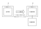
切替パターンA(解析処理モード:OFF、マルチ画像表示モード:ON)の場合には、モード自動切替部69は、モノ発光が作動中の場合には、マルチ画像表示モードのOFFからONへの切り替えに従って、モノ発光からマルチ発光に自動的に切り替える。マルチ発光を行っているマルチ画像表示モード中においては、モード自動切替部69は、予め設定したマルチ画像表示許容条件(光源切替条件)を満たす場合には、マルチ発光を継続する。一方、マルチ画像表示許容条件を満たさない場合に、マルチ発光からモノ発光に自動的に切り替える。この場合には、図8に示すように、第1観察画像と第2観察画像をディスプレイ18に自動的に切り替えて表示する状態から、通常画像のみを連続してディスプレイ18に表示する状態に切り替える処理を行う。即ち、モノ画像表示モードに自動的に切り替えられる。
In the case of switching pattern A (analysis processing mode: OFF, multi-image display mode: ON), the mode
なお、ユーザーにとって、マルチ画像表示モードとモノ画像表示モードのいずれに設定されているかが分かりにくい場合があるため、ディスプレイ18には、マルチ発光中の場合には「マルチ画像表示モード」である旨の表示がされ、モノ発光の場合には「モノ画像表示モード」である旨の表示がされている。
Note that since it may be difficult for the user to understand whether the mode is set to multi-image display mode or mono-image display mode, the
マルチ画像表示許容条件を満たさない場合としては、例えば、マルチ画像表示モードの使用時間が、予め定めた時間用閾値以上となることとする。この場合には、プロセッサ装置16内に設けられた時間計測部(図示しない)において、モード切替SW13aにより、マルチ画像表示モードに設定されてからの時間が計測される。そして、計測した時間が時間用閾値以上となった場合に、図9に示すように、マルチ発光からモノ発光に自動的に切り替える。これに従って、マルチ画像表示モードからモノ画像表示モードに自動的に切り替わる。
The case where the multi-image display permission condition is not satisfied is, for example, when the usage time of the multi-image display mode is equal to or longer than a predetermined time threshold. In this case, a time measurement section (not shown) provided in the
また、マルチ画像表示許容条件を満たさない場合としては、例えば、観察対象の静止画の保存回数が、予め定めた回数用閾値以上となることとする。この場合には、プロセッサ装置16内に設けられた回数カウント部(図示しない)において、静止画取得指示部13bが操作された回数をカウントする。そして、カウントした回数が回数用閾値以上となった場合に、図10に示すように、マルチ発光からモノ発光に自動的に切り替える。これに従って、マルチ画像表示モードからモノ画像表示モードに自動的に切り替わる。
Further, the case where the multi-image display permission condition is not satisfied is, for example, when the number of times a still image to be observed is saved is equal to or greater than a predetermined number-of-times threshold. In this case, a frequency counting unit (not shown) provided in the
また、マルチ画像表示許容条件を満たさない場合としては、観察対象に関する撮影条件が変化する場合とすることが好ましい。この場合には、撮影条件を取得するために、プロセッサ装置16の画像処理部60内に撮影条件取得部70が設けられる。撮影条件取得部70は、図11に示すように、観察部位取得部72と、明るさ算出部74と、倍率取得部76と、観察距離取得部78と、ブレ量算出部80とを備えている。
Furthermore, it is preferable that the case where the multi-image display permission condition is not satisfied is a case where the photographing conditions regarding the observation object change. In this case, a photographing
マルチ画像表示許容条件を満たさない場合として、撮影条件の一つである観察部位が変化した場合は、例えば、現在撮影を行っている観察部位が、第1の部位(例えば、「食道」)から第2の部位(例えば、「胃」)に変化した場合、または第2の部位から第1の部位に変化した場合、図12に示すように、マルチ発光からモノ発光に自動的に切り替える。観察部位が変化する場合は、内視鏡の先端部12dが移動していると考えられ、交互に発光される第1照明光または第2照明光が観察対象に確実に照明されないことがあり、このような場合は、マルチ発光に適さない。
If the observation site, which is one of the imaging conditions, changes when the multi-image display permission conditions are not met, for example, the observation site currently being photographed changes from the first site (e.g., "oesophagus"). When changing to the second region (for example, "stomach") or from the second region to the first region, the multi-light emission is automatically switched to the mono-light emission, as shown in FIG. 12. When the observation site changes, the
観察部位に関する情報については、観察部位取得部72において取得する。観察部位取得部72は、マルチ発光において得られる第1観察画像又は第2観察画像の画像的特徴量から、観察部位を判定する。例えば、第1観察画像又は第2観察画像において画面中央部が他の周辺部よりも明るさが暗い場合には、観察部位は「食道」であると判定される。また、第1観察画像又は第2観察画像において画面中央部が他の周辺部よりも明るさが明るい場合には、観察部位は「胃」であると判定される。
Information regarding the observed region is acquired by the observed
マルチ画像表示許容条件を満たさない場合として、撮影条件の一つである観察対象の明るさが、第1明るさ用閾値以下、又は第1明るさ用閾値より大きい第2明るさ用閾値以上となる場合は、図13に示すように、マルチ発光からモノ発光に自動的に切り替える。これに従って、マルチ画像表示モードからモノ画像表示モードに自動的に切り替わる。明るさが第1明るさ用閾値以下の場合には、観察対象全体が暗いため、マルチ発光に適さない状態となっている。同様にして、明るさが第2明るさ用閾値以上の場合には、ハレーションが生じている場合など、観察対象全体が極めて明るいため、マルチ発光に適さない状態となっている。なお、明るさに関する情報は、明るさ算出部74において取得する。明るさ算出部74は、第1観察画像または第2観察画像から画素値の平均値を算出し、算出した画素値の平均値から明るさを算出する。ここで、画素値の平均値が大きければ大きいほど、明るさは大きくなる。
As a case where the multi-image display permissible conditions are not satisfied, the brightness of the observation target, which is one of the shooting conditions, is less than or equal to the first brightness threshold, or more than or equal to the second brightness threshold that is larger than the first brightness threshold. In this case, as shown in FIG. 13, the multi-light emission is automatically switched to mono-light emission. Accordingly, the multi-image display mode is automatically switched to the mono-image display mode. If the brightness is less than or equal to the first brightness threshold, the entire observation target is dark and is not suitable for multiple light emission. Similarly, when the brightness is equal to or higher than the second brightness threshold, the entire observation target is extremely bright, such as when halation is occurring, and is therefore in a state unsuitable for multi-light emission. Note that the information regarding brightness is acquired by the
マルチ画像表示許容条件を満たさない場合として、撮影条件の一つである観察対象の倍率について、倍率変化量が倍率用閾値を超えた場合に、図14に示すように、マルチ発光からモノ発光に自動的に切り替える。これに従って、マルチ画像表示モードからモノ画像表示モードに自動的に切り替わる。観察対象の倍率が大きく変化して、倍率変化量が倍率用閾値を超えるような場合には、観察対象に対する照明光の照明分布が変化して、マルチ発光に適さない場合が多い。なお、観察対象の倍率については、ズーム操作部13cが操作される毎に、いずれの倍率に設定されたかのズーム情報が倍率取得部76に送信される。モード自動切替部69は、倍率取得部76にて取得したズーム情報を参照して、倍率変化量が倍率用閾値を超えたか否かを判定する。
As a case where the multi-image display permissible conditions are not met, if the magnification change of the observation target, which is one of the shooting conditions, exceeds the magnification threshold, the multi-image display will change from the multi-image display to the mono-emission, as shown in Figure 14. Switch automatically. Accordingly, the multi-image display mode is automatically switched to the mono-image display mode. If the magnification of the observation target changes significantly and the amount of change in magnification exceeds the magnification threshold, the illumination distribution of the illumination light on the observation target changes, which is often not suitable for multi-light emission. Regarding the magnification of the observation target, each time the
マルチ画像表示許容条件を満たさない場合として、撮影条件の一つである観察距離(内視鏡の先端部12dと観察対象との距離)について、観察距離の変化量が距離用閾値を超えた場合に、図15に示すように、マルチ発光からモノ発光に自動的に切り替える。これに従って、マルチ画像表示モードからモノ画像表示モードに自動的に切り替わる。観察対象の倍率と同様に、観察距離が大きく変化して、観察距離の変化量が距離用閾値を超えるような場合には、観察対象に対する照明光の照明分布が変化して、マルチ発光に適さない場合が多い。なお、観察距離については、観察距離取得部78が、マルチ発光にて得られる第1観察画像または第2観察画像から画素値の平均値を算出し、算出した画素値の平均値から観察距離を求める。ここで、画素値の平均値が大きければ大きいほど、観察距離は小さいとされる。
The case where the multi-image display permissible conditions are not met is when the amount of change in the observation distance (distance between the
マルチ画像表示許容条件を満たさない場合として、撮影条件の一つである画像のブレ量がブレ量用閾値を超えた場合に、図16に示すように、マルチ発光からモノ発光に自動的に切り替える。これに従って、マルチ画像表示モードからモノ画像表示モードに自動的に切り替わる。画像のブレ量が大きく、ブレ量がブレ量用閾値を超えるような場合には、照明光が確実に観察対象に当たらない場合があり、マルチ発光に適さない場合が多い。なお、ブレ量については、ブレ量算出部80が、マルチ発光にて得られる第1観察画像または第2観察画像からコントラストを求め、コントラストからブレ量を算出する。コントラストが低くなるほど、ブレ量が大きくなる。ブレ量の算出方法としては、コントラストを用いる他、第1観察画像または第2観察画像の周波数成分から算出するようにしてもよい(周波数成分が低周波の成分となるほど、ブレ量が大きくなる)。
If the multi-image display permissible conditions are not met, and the amount of image blur, which is one of the shooting conditions, exceeds the blur amount threshold, the multi-flash mode is automatically switched to mono-flash mode, as shown in Figure 16. . Accordingly, the multi-image display mode is automatically switched to the mono-image display mode. If the amount of blur in the image is large and exceeds the blur amount threshold, the illumination light may not reliably hit the observation target and is often not suitable for multi-light emission. Regarding the amount of blur, the amount of
以上のように、マルチ発光からモノ発光への自動切替に用いるマルチ画像表示許容条件については、ユーザーにより適宜設定可能である。この場合には、ユーザーはユーザーインターフェース19を操作して、図17に示すマルチ画像表示許容条件設定メニュー82をディスプレイ18に表示させる。このマルチ画像表示許容条件設定メニュー82においては、「時間用閾値」、「回数用閾値」の設定を行うことができる。「時間用閾値」の場合であれば、マルチ画像表示許容条件設定メニュー82にて「100秒」に設定すると、マルチ画像表示モードの使用時間が「100秒」に達した時点で、マルチ発光からモノ発光に自動的に切り替えられる。また、「回数用閾値」の場合であれば、マルチ画像表示許容条件設定メニュー82にて「40回」に設定すると、静止画取得指示部13bの操作回数が「40回」に達した時点で、マルチ発光からモノ発光に自動的に切り替えられる。
As described above, the multi-image display permission conditions used for automatic switching from multi-emission to mono-emission can be set as appropriate by the user. In this case, the user operates the
なお、後述するように、モノ発光からマルチ発光への自動切替に用いるマルチ画像表示再開条件については、マルチ画像表示許容条件設定メニュー82と同様のマルチ画像表示再開条件設定メニューをディスプレイ18に表示して、適宜設定できるようにすることが好ましい。
As will be described later, regarding the multi-image display resumption conditions used for automatic switching from mono-emission to multi-emission, a multi-image display resumption condition setting menu similar to the multi-image display permissible condition setting menu 82 is displayed on the
また、マルチ画像表示許容条件設定メニュー82においては、「第1の部位」、「第2の部位」の設定を行うことができる。「第1の部位」を「食道」とし、「第2の部位」を「胃」として設定した場合には、観察部位が「食道」から「胃」に変わった場合、又は「胃」から「食道」に変わった場合に、マルチ発光からモノ発光に自動的に切り替えられる。また、マルチ画像表示許容条件設定メニュー82においては、「第1明るさ用閾値」、「第2明るさ用閾値」の設定を行うことができる。「第1明るさ用閾値」をP1とし、「第2明るさ用閾値」をP2(>P1)として設定した場合には、観察対象の明るさがP1以下、又はP2位以上となった場合に、マルチ発光からモノ発光に自動的に切り替えられる。 Furthermore, in the multi-image display permission condition setting menu 82, settings for "first region" and "second region" can be made. If the "first part" is set as "oesophagus" and the "second part" is set as "stomach", if the observation part changes from "oesophagus" to "stomach", or from "stomach" to "stomach", If the esophagus changes, it will automatically switch from multi-luminescence to mono-luminescence. Furthermore, in the multi-image display permission condition setting menu 82, it is possible to set a "first brightness threshold" and a "second brightness threshold". When the "first brightness threshold" is set to P1 and the "second brightness threshold" is set to P2 (>P1), if the brightness of the observation target is below P1 or above P2 You can automatically switch from multi-flash to mono-flash.
また、マルチ画像表示許容条件設定メニュー82においては、「倍率用閾値」の設定を行うことができる。「倍率用閾値」を「5倍」とした場合には、観察対象の倍率変化量が「5倍」を超えた時点で、マルチ発光からモノ発光に自動的に切り替えられる。また、マルチ画像表示許容条件設定メニュー82においては、「距離用閾値」の設定を行うことができる。「距離用閾値」をLxとした場合には、観察距離の変化量がLxを超えた場合に、マルチ発光からモノ発光に自動的に切り替えられる。また、マルチ画像表示許容条件設定メニュー82においては、「ブレ量用閾値」の設定を行うことができる。「ブレ量用閾値」をBrに設定した場合には、ブレ量がBrを超えた場合に、マルチ発光からモノ発光に自動的に切り替えられる。 Further, in the multi-image display permission condition setting menu 82, a "magnification threshold" can be set. When the "threshold for magnification" is set to "5x", when the amount of change in magnification of the observation target exceeds "5x", the multi-emission is automatically switched to mono-emission. Further, in the multi-image display permission condition setting menu 82, a "threshold for distance" can be set. When the "threshold for distance" is set to Lx, when the amount of change in observation distance exceeds Lx, the multi-light emission is automatically switched to mono-light emission. Further, in the multi-image display permissible condition setting menu 82, a "shake amount threshold" can be set. When the "shake amount threshold" is set to Br, when the blur amount exceeds Br, the multi-light emission is automatically switched to mono-light emission.
モード自動切替部69は、マルチ画像表示許容条件を満たさなくなることにより、マルチ発光からモノ発光に自動的に切り替わり、且つ、マルチ画像表示モードからモノ画像表示モードに自動的に切り替えられた場合において、図18に示すように、予め設定されたマルチ画像表示再開条件(光源切替条件)を満たした場合に、モノ発光からマルチ発光に自動的に切り替え、且つ、マルチ画像表示モードを作動させる。観察対象に関する撮影条件が変化した場合などに、モノ発光に自動的に切り替えているが、観察対象に関する撮影条件の変化がマルチ発光許容範囲内である場合など、マルチ画像表示再開条件を満たした場合などには、モノ発光からマルチ発光に自動的に切り替えることが好ましい。なお、撮影条件の変化がマルチ発光許容範囲内であるとは、撮影条件の変化によっても、マルチ発光によって得られる第1の観察画像と第2の観察画像の切り替え表示に対する視認性に影響を与えないことをいう。
The automatic
マルチ画像表示再開条件は、観察対象が、第1の部位(例えば、「食道」)から第2の部位(例えば、「胃」)に変わってから、一定時間内に第1の部位に戻った場合、または、第2の部位から第1の部位に変わってから、一定時間内に第2の部位に戻った場合であることが好ましい。この場合には、図19に示すように、モノ発光からマルチ発光に自動的に切り替える。これに従って、モノ画像表示モードからマルチ画像表示モードに自動的に切り替わる。観察部位が直ぐに元の部位に戻った場合には、照明条件がそれほど変化せず、マルチ発光による発光状態に影響を与えないためである。なお、観察部位に関する情報については、上記と同様に、観察部位取得部72において取得する。
The multi-image display resumption condition is that the observation target changes from a first region (e.g., "esophagus") to a second region (e.g., "stomach") and then returns to the first region within a certain period of time. It is preferable that the subject change from the second site to the first site and then return to the second site within a certain period of time. In this case, as shown in FIG. 19, mono-emission is automatically switched to multi-emission. Accordingly, the mono-image display mode is automatically switched to the multi-image display mode. This is because if the observation site immediately returns to the original site, the illumination conditions will not change much and the light emission state by multi-light emission will not be affected. Note that information regarding the observed region is acquired by the observed
マルチ画像表示再開条件は、観察対象の明るさが、第1明るさ用閾値以上、または第2明るさ用閾値以下となった場合であることが好ましい。この場合には、図20に示すように、モノ発光からマルチ発光に自動的に切り替える。これに従って、モノ画像表示モードからマルチ画像表示モードに自動的に切り替わる。明るさが暗くなったり、又は、明るくなったりしても、一定時間後に、元の通常の明るさ(第1明るさ用閾値以上、または第1明るさ用閾値以下)に戻った場合には、マルチ発光による発光状態に影響を与えないためである。なお、明るさに関する情報については、上記と同様に、明るさ算出部74において取得する。
It is preferable that the multi-image display restart condition is a case in which the brightness of the observation target becomes greater than or equal to the first brightness threshold or less than or equal to the second brightness threshold. In this case, as shown in FIG. 20, mono-emission is automatically switched to multi-emission. Accordingly, the mono-image display mode is automatically switched to the multi-image display mode. Even if the brightness becomes darker or brighter, if it returns to the original normal brightness (more than the first brightness threshold or less than the first brightness threshold) after a certain period of time, This is because it does not affect the light emission state due to multiple light emission. Note that information regarding brightness is obtained by the
マルチ画像表示再開条件は、観察対象の倍率を変化させる場合において、観察対象の倍率変化量が倍率用閾値未満であることが好ましい。この場合には、図21に示すように、モノ発光からマルチ発光に自動的に切り替える。これに従って、モノ画像表示モードからマルチ画像表示モードに自動的に切り替わる。観察対象の倍率の変化がそれほど大きくなく、倍率変化量が倍率用閾値を超えたのが一時的であり、直ぐに、倍率用閾値未満に収まったような場合には、マルチ発光による発光状態に影響を与えないためである。なお、観察対象の倍率については、上記と同様に、倍率取得部76において取得する。
When the multi-image display restart condition is to change the magnification of the observation target, it is preferable that the amount of change in the magnification of the observation target is less than the magnification threshold. In this case, as shown in FIG. 21, mono-emission is automatically switched to multi-emission. Accordingly, the mono-image display mode is automatically switched to the multi-image display mode. If the change in magnification of the observation target is not that large and the amount of change in magnification exceeds the magnification threshold only temporarily and then quickly falls below the magnification threshold, the light emitting state by multi-flash may be affected. This is to avoid giving Note that the magnification of the observation target is acquired by the
マルチ画像表示再開条件は、観察距離の変化量が距離用閾値以下となった場合であることが好ましい。この場合には、図22に示すように、モノ発光からマルチ発光に自動的に切り替える。これに従って、モノ画像表示モードからマルチ画像表示モードに自動的に切り替わる。観察距離の変化がそれほど大きくなく、観察距離の変化量が距離用閾値を超えたのが一時的であり、直ぐに、距離用閾値未満に収まったような場合には、マルチ発光による発光状態に影響を与えないためである。なお、観察距離については、上記と同様に、観察距離取得部78において取得する。
It is preferable that the multi-image display restart condition is a case where the amount of change in the observation distance becomes equal to or less than a distance threshold. In this case, as shown in FIG. 22, mono-emission is automatically switched to multi-emission. Accordingly, the mono-image display mode is automatically switched to the multi-image display mode. If the change in observation distance is not that large and the amount of change in observation distance exceeds the threshold for distance only temporarily, but soon falls below the threshold for distance, it will affect the light emission state by multi-flash. This is to avoid giving. Note that the observation distance is acquired by the observation
マルチ画像表示再開条件は、観察画像のブレ量がブレ量用閾値以下となった場合であることが好ましい。この場合には、図23に示すように、モノ発光からマルチ発光に自動的に切り替える。これに従って、モノ画像表示モードからマルチ画像表示モードに自動的に切り替わる。画像のブレ量がそれほど大きくなく、ブレ量がブレ量用閾値を超えたのが一時的であり、直ぐに、ブレ量用閾値未満に収まったような場合には、マルチ発光による発光状態に影響を与えないためである。なお、ブレ量については、上記と同様に、ブレ量算出部80において算出する。
The multi-image display restart condition is preferably a case where the amount of blur in the observed image becomes equal to or less than a threshold for the amount of blur. In this case, as shown in FIG. 23, mono-emission is automatically switched to multi-emission. Accordingly, the mono-image display mode is automatically switched to the multi-image display mode. If the amount of blur in the image is not very large, and the amount of blur exceeds the threshold for blur amount only temporarily, and then quickly falls below the threshold for blur amount, the light emitting state by multi-flash may be affected. This is to avoid giving. Note that the amount of blur is calculated by the amount of
ただし、意図せずに、マルチ発光に自動的に切り替わること(マルチ画像表示モードに自動的に切り替わること)を防ぐため、モード自動切替部69は、マルチ画像表示再開条件を満たし、且つ、再開許容条件を満たす場合に、モノ発光からマルチ発光に自動的に切り替え、且つ、モノ画像表示モードからマルチ画像表示モードに自動的に切り替える。一方、マルチ画像表示再開条件を満たし、且つ、再開許容条件(光源切替条件)を満たさない場合に、マルチ発光に自動的に切り替えることを禁止することが好ましい。再開許容条件は、ユーザーにより設定可能であることが好ましい。また、再開許容条件が満たすか否かを判定するために、再開許容条件を示す再開許容有無フラグが用いられる。再開許容有無フラグが「1」であることは、再開許容条件を満たさないことを表し、再開許容有無フラグが「0」であることは、再開許容条件を満たすことを表す(図18~図23参照)。
However, in order to prevent unintentional automatic switching to multi-light emission (automatic switching to multi-image display mode), the automatic
再開許容条件は、解析処理モードがOFFであり、且つ、ユーザーが、モード切替SW13aによってモノ画像表示モードを選択していない場合であることが好ましい。ユーザーがモノ発光を選択した場合には、再開許容有無フラグが「0」となり、モノ発光を選択しない場合には、再開許容有無フラグが「1」となる。ユーザーが自発的にモノ画像表示モードを選択する場合には、マルチ発光に自動的に切り替えないことが好ましい。
Preferably, the restart permission condition is that the analysis processing mode is OFF and the user has not selected the mono image display mode using the
再開許容条件は、解析処理モードがOFFであり、且つ、マルチ画像表示許容条件を満たしてマルチ発光からモノ発光に自動的に切り替えてから、再開許容時間を経過していない場合であることが好ましい。この場合には、時間計測部(図示しない)において、モノ発光に切り替えてからの時間が計測される。計測した時間が再開許容時間を経過してない場合には、再開許容有無フラグを「1」で維持する。そして、計測した時間が再開許容時間を経過した場合には、再開許容有無フラグを「0」に切り替える。再開許容時間を経過した後は、モノ発光に基づく観察に適した状態と考えられるため、マルチ発光に自動的に切り替えないことが好ましい。 Preferably, the restart permissible condition is that the analysis processing mode is OFF, and the restart permissible time has not elapsed since the multi-image display permissible condition was met and the multi-image display was automatically switched to mono-emission. . In this case, a time measuring section (not shown) measures the time elapsed after switching to mono-emission mode. If the measured time has not passed the restart permissible time, the restart permissible flag is maintained at "1". Then, when the measured time has passed the restart permissible time, the restart permissible flag is switched to "0". After the restart permissible time has elapsed, it is considered that the state is suitable for observation based on mono-emission, so it is preferable not to automatically switch to multi-emission.
再開許容条件は、解析処理モードがOFFであり、且つ、マルチ発光の実施が可能である場合であることが好ましい。マルチ発光の実施が可能又は不可の判定については、プロセッサ装置16のマルチ発光実施可能判定部(図示しない)が行う。具体的には、マルチ発光実施可能判定部は、内視鏡12、光源装置14、及びプロセッサ装置16に関する異常などを検出し、検出結果に基づいて、マルチ発光の実施可能又は実施不可を判定する。この場合には、マルチ発光実施可能判定部が、マルチ発光が実施可能と判定した場合には、再開許容有無フラグを「1」とし、マルチ発光が実施不可と判定した場合には、再開許容有無フラグを「0」とする。内視鏡12、光源装置14、及びプロセッサ装置16に関する異常などが生じて、マルチ発光の実施が難しくなった場合には、マルチ発光に自動的に切り替えないことが好ましい。
Preferably, the restart permission condition is that the analysis processing mode is OFF and that multiple light emission is possible. The determination as to whether multi-light emission is possible or not is performed by a multi-light emission enablement determination unit (not shown) of the
再開許容条件は、解析処理モードがOFFであり、且つ、倍率変更部の使用又は不使用の切替が行われていない場合であることが好ましい。倍率変更部の使用とは、ズーム操作部13cを「ON」にして倍率変更が可能な状態をいう。倍率変更部の不使用とは、ズーム操作部13cを「OFF」にして倍率変更をしない状態をいう。この場合には、マルチ画像表示許容条件を満たしてモノ発光に自動的に切り替えられた後、倍率変更部の使用又は不使用の切り替えがない場合には、再開許容有無フラグを「1」とする一方、倍率変更部の使用又は不使用が切り替えられた場合には、再開許容有無フラグを「0」とする。倍率変更部の使用又は不使用の切替えが行われた場合には、前回のマルチ発光の場合とは異なる対象を観察し、必ずしもマルチ発光を使用するとは限らないことから、マルチ発光に自動的に切り替えないことが好ましい。
Preferably, the restart permission condition is that the analysis processing mode is OFF and the magnification changing unit is not switched between use and non-use. Use of the magnification changing section refers to a state in which the
切替パターンB(解析処理モード:ON、マルチ画像表示モード:OFF)の場合には、モード自動切替部69は、モノ発光が作動中の場合には、解析処理モードのOFFからONへの切り替えに従って、モノ発光からマルチ発光に自動的に切り替える。マルチ発光を行っている解析処理モード中においては、モード自動切替部69は、予め設定した解析処理許容条件(光源切替条件)を満たす場合には、マルチ発光からモノ発光に自動的に切り替えることを禁止する。一方、モード自動切替部69は、解析処理許容条件を満たさない場合には、マルチ発光からモノ発光に自動的に切り替わる。これに従って、図24に示すように、解析結果付き表示用画像をディスプレイ18に表示する解析処理モードから、通常画像のみをディスプレイ18に表示するモノ画像表示モードに自動的に切り替わる。
In the case of switching pattern B (analysis processing mode: ON, multi-image display mode: OFF), the automatic
なお、解析処理許容条件としては、例えば、観察対象に関する撮影条件の変化が解析処理許容範囲内であることが好ましい。解析処理許容範囲内とは、撮影条件の変化によっても、解析処理を一定の精度で行なうことが可能であることをいう。解析処理許容範囲内の具体例としては、ハレーションや暗部などの解析処理の影響を与えうる領域が、第2画像信号に基づく画面内に占める面積が一定以下の場合である。一方、解析処理許容範囲外の具体例としては、ハレーションや暗部などの解析処理の影響を与えうる領域が、第2画像信号に基づく画面内に占める面積が一定を超える場合である。 Note that, as the analysis processing permissible condition, for example, it is preferable that a change in the photographing conditions regarding the observation object be within the analysis processing permissible range. The term "within the analysis processing tolerance range" means that the analysis processing can be performed with a certain degree of accuracy even when the photographing conditions change. A specific example of the analysis processing tolerance is a case where an area that can be affected by the analysis processing, such as halation or dark areas, occupies a certain area or less within the screen based on the second image signal. On the other hand, a specific example of being outside the allowable range for analysis processing is when an area that can be affected by analysis processing, such as halation or dark areas, occupies an area in the screen based on the second image signal that exceeds a certain value.
なお、解析処理モードからモノ画像表示モードに自動的に切り替わった場合には、モード自動切替部69は、予め定められた解析処理再開条件(光源切替条件)を満たした場合には、モノ画像表示モードから解析処理モードに自動的に切り替えるようにしてもよい。この場合、モード自動切替部69は、解析処理再開条件を満たした場合であっても、再開許容条件(上記と同様であることが好ましい。)を満たさない場合には、解析処理モードへの自動的な切替を禁止することが好ましい。なお、解析処理再開条件は、マルチ画像表示再開条件と同じでもよく、異なってもよい。
Note that when the analysis processing mode is automatically switched to the mono image display mode, the automatic
切替パターンC(解析処理モード:ON、マルチ画像表示モード:ON)の場合には、モード自動切替部69は、モノ発光が作動中の場合には、解析処理モード及びマルチ画像表示モードのOFFからONへの切り替えに従って、モノ発光からマルチ発光に自動的に切り替える。これに従って、解析結果付き表示用画像がディスプレイ18に表示され、且つ、第1観察画像と第2観察画像とが自動的に切り替わってディスプレイ18に表示される(図25~図27参照)。
In the case of switching pattern C (analysis processing mode: ON, multi-image display mode: ON), the automatic
マルチ発光を行っている解析処理モード及びマルチ画像表示モード中においては、モード自動切替部69は、マルチ画像表示許容条件を満たさない場合であっても、解析処理許容条件を満たす場合には、マルチ発光からモノ発光に自動的に切り替えることを禁止する。この場合には、図25に示すように、ディスプレイ18上では第1観察画像と第2観察画像との自動切替表示が停止する一方で、ディスプレイ18上での解析結果付き表示用画像の表示が継続される。
In the analysis processing mode and multi-image display mode in which multi-light emission is performed, the mode
また、マルチ発光を行っている解析処理モード及びマルチ画像表示モード中においては、モード自動切替部69は、マルチ画像表示許容条件を満たした場合であっても、解析処理許容条件を満さない場合には、マルチ発光からモノ発光に自動的に切り替えることを禁止する。この場合には、図26に示すように、ディスプレイ18上での解析結果付き表示用画像の表示が停止する一方で、ディスプレイ18上での第1観察画像と第2観察画像との自動切替表示が継続される。
In addition, in the analysis processing mode and multi-image display mode in which multiple flashes are performed, even if the multi-image display permission conditions are satisfied, if the analysis processing permission conditions are not satisfied, the mode
また、マルチ発光を行っている解析処理モード及びマルチ画像表示モード中においては、モード自動切替部69は、マルチ画像表示許容条件を満たさず、且つ、解析処理許容条件を満さない場合には、マルチ発光からモノ発光に自動的に切り替えられる。これに従って、図27に示すように、通常画像のみをディスプレイ18に表示するモノ画像表示モードに切り替わる。
In addition, in the analysis processing mode and multi-image display mode in which multiple light emission is performed, the mode
なお、切替パターンCにおいても、解析処理モードからモノ画像表示モードに自動的に切り替わった場合には、モード自動切替部69は、予め定められた解析処理再開条件を満たした場合には、モノ画像表示モードから解析処理モードに自動的に切り替えるようにしてもよい。モード自動切替部69は、解析処理再開条件を満たした場合であっても、再開許容条件を満たさない場合には、解析処理モードへの自動的な切替を禁止することが好ましい。
Note that also in switching pattern C, when the analysis processing mode is automatically switched to the mono image display mode, the mode
また、切替パターンCにおいても、マルチ画像表示モードからモノ画像表示モードに自動的に切り替わった場合には、モード自動切替部69は、予め定められたマルチ画像表示再開条件を満たした場合には、モノ画像表示モードからマルチ画像表示モードに自動的に切り替えるようにしてもよい。モード自動切替部69は、マルチ画像表示再開条件を満たした場合であっても、再開許容条件を満たさない場合には、マルチ画像表示モードへの自動的な切替を禁止することが好ましい。
Also, in switching pattern C, when the multi-image display mode is automatically switched to the mono-image display mode, the mode
次に、切替パターンA(解析処理モード:OFF、マルチ画像表示モード:ON)の場合の一連の流れについて、図28に示すフローチャートに沿って説明する。マルチ画像表示モードにおいては、第1照明光と第2照明光とが、特定の発光パターン(本実施形態では2フレーム間隔)に従って、切り替えて発光される。そして、第1照明光により照明された観察対象を撮像して得られる第1観察画像と、第2照明光により照明された観察対象を撮像して得られる第2観察画像とを、特定の表示パターン(本実施形態では2フレーム間隔)に従って、切り替えてディスプレイ18に表示される。
Next, a series of steps in the case of switching pattern A (analysis processing mode: OFF, multi-image display mode: ON) will be described along the flowchart shown in FIG. In the multi-image display mode, the first illumination light and the second illumination light are switched and emitted according to a specific light emission pattern (in this embodiment, at two-frame intervals). A first observation image obtained by capturing an observation target illuminated by the first illumination light and a second observation image obtained by capturing an observation target illuminated by the second illumination light are displayed in a specific display. The images are switched and displayed on the
マルチ画像表示許容条件を満たす限りにおいては、マルチ画像表示モードは継続する。そして、予め定めたマルチ画像表示許容条件を満たさなくなった場合に、マルチ発光からモノ発光に自動的に切り替える。これに従って、マルチ画像表示モードからモノ画像表示モードに自動的に切り替わる。 The multi-image display mode continues as long as the multi-image display permission conditions are met. Then, when the predetermined multi-image display permission condition is no longer satisfied, the multi-light emission is automatically switched to mono-light emission. Accordingly, the multi-image display mode is automatically switched to the mono-image display mode.
マルチ画像表示許容条件を満たさない場合としては、マルチ発光の使用時間が時間用閾値を超えた場合や、静止画の保存回数が回数用閾値を超えた場合などがある。その他、マルチ画像表示許容条件を満たさない場合として、観察対象に関する撮影条件が変化した場合がある。モノ発光に自動的に切り替えられる(モノ画像表示モードへの切替)と、第1照明光と第2照明光の切替発光は停止される。これに合わせて、第1観察画像と第2観察画像の切替表示も停止される。そして、通常光が発光され、通常光により照明された観察対象を撮像して得られる通常画像がディスプレイ18に表示される。
Cases in which the multi-image display permission condition is not satisfied include a case where the usage time of multi-light emission exceeds a time threshold, a case where the number of times a still image is saved exceeds a number-of-time threshold, and so on. In addition, as a case where the multi-image display permission condition is not satisfied, there is a case where the photographing conditions regarding the observation object have changed. When the light is automatically switched to mono-emission (switching to mono-image display mode), the switching light emission between the first illumination light and the second illumination light is stopped. At the same time, the switching display of the first observation image and the second observation image is also stopped. Then, normal light is emitted, and a normal image obtained by imaging the observation target illuminated by the normal light is displayed on the
モノ画像表示モードに自動的に切り替えられた後は、プロセッサ装置16において、マルチ画像表示再開条件を満たすか否かが監視される。マルチ画像表示再開条件を満たし、且つ、再開許容条件を満たす場合には、モノ発光からマルチ発光に自動的に切り替える。これに従って、モノ画像表示モードからマルチ画像表示モードへの切替えが行われる。一方、マルチ画像表示再開条件を満たしても、再開許容条件を満たさない場合には、マルチ発光に自動的に切り替えることを禁止する。また、マルチ画像表示再開条件を満たさない場合にも、マルチ発光に自動的に切り替えることを禁止する。マルチ発光への自動的な切替が禁止された場合には、モノ画像表示モードを継続する。
After the mode is automatically switched to the mono image display mode, the
次に、切替パターンB(解析処理モード:ON、マルチ画像表示モード:OFF)の一連の流れについて、図29に示すフローチャートに沿って説明する。解析処理モードの場合には、第1照明光と第2照明光とが、特定の発光パターンに従って、切り替えて発光される。そして、第2照明光により照明された観察対象を撮像して得られる第2画像信号に対して、解析処理が行われる。そして、第1照明光により照明された観察対象を撮像して得られる第1画像信号に基づく表示用画像に対して、解析処理の解析結果を重畳表示することにより、解析結果付き表示用画像が得られる。解析結果付き表示用画像は、ディスプレイ18に表示される。
Next, a series of flows of switching pattern B (analysis processing mode: ON, multi-image display mode: OFF) will be explained along the flowchart shown in FIG. 29. In the analysis processing mode, the first illumination light and the second illumination light are switched and emitted according to a specific light emission pattern. Then, analysis processing is performed on the second image signal obtained by imaging the observation target illuminated with the second illumination light. Then, by superimposing and displaying the analysis results of the analysis process on the display image based on the first image signal obtained by imaging the observation target illuminated by the first illumination light, the display image with the analysis results is created. can get. The display image with analysis results is displayed on the
解析処理許容条件を満たす限りにおいては、解析処理モードは継続する。そして、予め定めた解析処理許容条件を満たさなくなった場合に、マルチ発光からモノ発光に自動的に切り替える。これに従って、解析処理モードからモノ画像表示モードに自動的に切り替わる。 As long as the analysis processing permission conditions are met, the analysis processing mode continues. Then, when the predetermined analysis processing permissible conditions are no longer satisfied, the multi-light emission is automatically switched to the mono-light emission. Accordingly, the analysis processing mode is automatically switched to the mono image display mode.
モノ画像表示モードに自動的に切り替えられた後は、プロセッサ装置16において、解析処理再開条件を満たすか否かが監視される。解析処理再開条件を満たし、且つ、再開許容条件を満たす場合には、モノ発光からマルチ発光に自動的に切り替える。これに従って、モノ画像表示モードから解析処理モードへの切替えが行われる。一方、解析処理再開条件を満たしても、再開許容条件を満たさない場合には、マルチ発光に自動的に切り替えることを禁止する。また、解析処理再開条件を満たさない場合にも、マルチ発光に自動的に切り替えることを禁止する。マルチ発光への自動的な切替が禁止された場合には、モノ画像表示モードを継続する。
After the mode is automatically switched to the mono image display mode, the
次に、切替パターンC(解析処理モード:ON、マルチ画像表示モード:ON)の一連の流れについて、図30に示すフローチャートに沿って説明する。解析処理モード及びマルチ画像表示モードを両方作動させる場合には、第1照明光と第2照明光とが、特定の発光パターンに従って、切り替えて発光される。そして、第2照明光により照明された観察対象を撮像して得られる第2画像信号に対して、解析処理が行われる。そして、第1照明光により照明された観察対象を撮像して得られる第1画像信号に基づく表示用画像に対して、解析処理の解析結果を重畳表示することにより、解析結果付き表示用画像が得られる。解析結果付き表示用画像は、ディスプレイ18に表示される。
Next, a series of flows of switching pattern C (analysis processing mode: ON, multi-image display mode: ON) will be explained along the flowchart shown in FIG. 30. When operating both the analysis processing mode and the multi-image display mode, the first illumination light and the second illumination light are emitted while being switched according to a specific light emission pattern. Then, analysis processing is performed on the second image signal obtained by imaging the observation target illuminated by the second illumination light. Then, by superimposing and displaying the analysis results of the analysis process on the display image based on the first image signal obtained by imaging the observation target illuminated by the first illumination light, the display image with the analysis results is created. can get. The display image with analysis results is displayed on the
また、ディスプレイ18においては、第1照明光により照明された観察対象を撮像して得られる第1観察画像と、第2照明光により照明された観察対象を撮像して得られる第2観察画像とを、特定の表示パターン(本実施形態では2フレーム間隔)に従って、切り替えて表示される。
The
解析処理許容条件及びマルチ画像表示許容条件を満たす限りにおいては、解析処理モードとマルチ画像表示モードは継続する。解析処理許容条件及びマルチ画像表示許容条件のうち一方を満たし、他方を満たさない場合には、マルチ発光からモノ発光に自動的に切替わることを禁止する。この場合、解析処理許容条件及びマルチ画像表示許容条件のうち条件を満たすモードについては継続し、条件を満たさないモードについては停止する。これに対して、解析処理許容条件を満たさず、且つ、マルチ画像表示許容条件を満たさなくなった場合に、マルチ発光からモノ発光に自動的に切り替える。これに従って、解析処理モード及びマルチ画像表示モードからモノ画像表示モードに自動的に切り替わる。 As long as the analysis processing permission condition and the multi-image display permission condition are satisfied, the analysis processing mode and the multi-image display mode continue. If one of the analysis processing permission condition and the multi-image display permission condition is satisfied, but the other is not satisfied, automatic switching from multi-light emission to mono-light emission is prohibited. In this case, the mode that satisfies the analysis processing permission condition and the multi-image display permission condition is continued, and the mode that does not satisfy the condition is stopped. On the other hand, when the analysis processing permission conditions are not satisfied and the multi-image display permission conditions are no longer satisfied, the multi-light emission is automatically switched to the mono-light emission. Accordingly, the analysis processing mode and the multi-image display mode are automatically switched to the mono-image display mode.
モノ画像表示モードに自動的に切り替えられた後は、プロセッサ装置16において、解析処理再開条件及びマルチ画像表示再開条件を満たすか否かが監視される。解析処理再開条件を満たし、且つ、再開許容条件を満たす場合には、モノ発光からマルチ発光に自動的に切り替える。これに従って、解析処理モードに自動的に切り替えられる。また、マルチ画像表示再開条件を満たし、且つ、再開許容条件を満たす場合には、モノ発光からマルチ発光に自動的に切り替える。これに従って、マルチ画像表示モードに自動的に切り替えられる。
After the mode is automatically switched to the mono image display mode, the
なお、上記実施形態においては、第1照明光と第2照明光とを、特定の発光パターンに従って、切り替えながら発光し、且つ、第1照明光に対応する第1観察画像と第2照明光に対応する第2観察画像とを、特定の表示パターンに従って、切り替えてディスプレイ18に表示するようにしているが、互いに波長帯域が異なる3種類以上の照明光を、特定の発光パターンに従って、切り替えながら発光し、且つ、各照明光に対応する3種類以上の観察画像を、特定の表示パターンに従って、切り替えてディスプレイ18に表示するようにしてもよい。
In the above embodiment, the first illumination light and the second illumination light are emitted while being switched according to a specific light emission pattern, and the first observation image and the second illumination light corresponding to the first illumination light are emitted. The corresponding second observation image is switched and displayed on the
上記実施形態において、画像取得部53、DSP56、ノイズ除去部58、画像処理部60、パラメータ切替部62、中央制御部68、モード自動切替部69など、プロセッサ装置16に含まれる処理部(processing unit)のハードウェア的な構造は、次に示すような各種のプロセッサ(processor)である。各種のプロセッサには、ソフトウエア(プログラム)を実行して各種の処理部として機能する汎用的なプロセッサであるCPU(Central Processing Unit)、FPGA (Field Programmable Gate Array) などの製造後に回路構成を変更可能なプロセッサであるプログラマブルロジックデバイス(Programmable Logic Device:PLD)、各種の処理を実行するために専用に設計された回路構成を有するプロセッサである専用電気回路などが含まれる。
In the embodiment described above, processing units included in the
1つの処理部は、これら各種のプロセッサのうちの1つで構成されてもよいし、同種または異種の2つ以上のプロセッサの組み合せ(例えば、複数のFPGAや、CPUとFPGAの組み合わせ)で構成されてもよい。また、複数の処理部を1つのプロセッサで構成してもよい。複数の処理部を1つのプロセッサで構成する例としては、第1に、クライアントやサーバなどのコンピュータに代表されるように、1つ以上のCPUとソフトウエアの組み合わせで1つのプロセッサを構成し、このプロセッサが複数の処理部として機能する形態がある。第2に、システムオンチップ(System On Chip:SoC)などに代表されるように、複数の処理部を含むシステム全体の機能を1つのIC(Integrated Circuit)チップで実現するプロセッサを使用する形態がある。このように、各種の処理部は、ハードウェア的な構造として、上記各種のプロセッサを1つ以上用いて構成される。 One processing unit may be composed of one of these various types of processors, or may be composed of a combination of two or more processors of the same type or different types (for example, multiple FPGAs or a combination of a CPU and an FPGA). may be done. Further, the plurality of processing units may be configured with one processor. As an example of configuring multiple processing units with one processor, first, as typified by computers such as clients and servers, one processor is configured with a combination of one or more CPUs and software, There is a form in which this processor functions as a plurality of processing units. Second, there are processors that use a single IC (Integrated Circuit) chip to implement the functions of an entire system including multiple processing units, as typified by System On Chip (SoC). be. In this way, various processing units are configured using one or more of the various processors described above as a hardware structure.
さらに、これらの各種のプロセッサのハードウェア的な構造は、より具体的には、半導体素子などの回路素子を組み合わせた形態の電気回路(circuitry)である。 Furthermore, the hardware structure of these various processors is, more specifically, an electric circuit (circuitry) in the form of a combination of circuit elements such as semiconductor elements.
10 内視鏡システム
12 内視鏡
12a 挿入部
12b 操作部
12c 湾曲部
12d 先端部
12e アングルノブ
13a モード切替SW
13b 静止画取得指示部
13c ズーム操作部
14 光源装置
16 プロセッサ装置
18 ディスプレイ
19 ユーザーインターフェース
20 光源部
20a V-LED(Violet Light Emitting Diode)
20b B-LED(Blue Light Emitting Diode)
20c G-LED(Green Light Emitting Diode)
20d R-LED(Red Light Emitting Diode)
21 光源用プロセッサ
23 光路結合部
30a 照明光学系
30b 撮像光学系
41 ライトガイド
45 照明レンズ
46 対物レンズ
47 ズームレンズ
47a ズーム駆動部
48 撮像センサ
50 CDS・AGC回路
52 A/D変換器
53 画像取得部
56 DSP(Digital Signal Processor)
58 ノイズ除去部
60 画像処理部
62 パラメータ切替部
63 静止画保存部
66 表示制御部
68 中央制御部
69 モード自動切替部
70 撮影条件取得部
72 観察部位取得部
74 明るさ算出部
76 倍率取得部
78 観察距離取得部
80 ブレ量算出部
82 マルチ画像表示許容条件設定メニュー
10
13b Still image
20b B-LED (Blue Light Emitting Diode)
20c G-LED (Green Light Emitting Diode)
20d R-LED (Red Light Emitting Diode)
21
52 A/
58
Claims (14)
前記複数の半導体光源を制御する光源用プロセッサであり、特定の照明光のみを発光するモノ発光と、互いに発光スペクトルが異なる第1照明光と第2照明光とを含む複数の照明光を、特定発光パターンに従って、切り替えながら発光するマルチ発光とに関する制御を行う光源用プロセッサと、
前記マルチ発光の場合において、前記第1照明光によって照明された観察対象を撮像して得られる第1画像信号と、前記第2照明光によって照明された前記観察対象を撮像して得られる第2画像信号とを出力する撮像センサと、
画像制御用プロセッサとを備え、
前記画像制御用プロセッサは、
前記第1画像信号に基づく表示用画像に対して、前記第2画像信号に基づく解析処理により得られた解析結果を表示する解析結果付き表示用画像をディスプレイに表示する解析処理モードを少なくとも作動させることが可能であり、
前記特定の照明光により照明された観察対象を撮像して得られる特定の観察画像をディスプレイに表示する制御を行うモノ画像表示モードを作動させることが可能であり、
前記第1画像信号に基づく第1の観察画像と前記第2画像信号に基づく第2の観察画像とを含む複数の観察画像を、特定の表示パターンに従って、切り替えて前記ディスプレイに表示する制御を行うマルチ画像表示モードを作動させることが可能であり、
前記画像制御用プロセッサは、
前記解析処理モードの作動又は非作動、前記マルチ画像表示モードの作動又は非作動、及び、予め定められた複数の光源切替条件の少なくとも1つに基づいて、前記モノ発光と前記マルチ発光との切替を自動的に行う内視鏡システムであって、
前記複数の光源切替条件のうち第1の光源切替条件に基づいて、前記モノ発光から前記マルチ発光への切替を自動的に行い、
前記複数の光源切替条件のうち前記第1の光源切替条件とは異なる第2の光源切替条件に基づいて、前記マルチ発光から前記モノ発光への切替を自動的に行う内視鏡システム。 a plurality of semiconductor light sources that emit light in different wavelength bands;
The light source processor controls the plurality of semiconductor light sources, and specifies a plurality of illumination lights including mono-emission that emits only specific illumination light and first illumination light and second illumination light that have different emission spectra from each other. a light source processor that controls multi-light emission that emits light while switching according to a light emission pattern;
In the case of the multi-light emission, a first image signal obtained by imaging the observation target illuminated by the first illumination light, and a second image signal obtained by imaging the observation target illuminated by the second illumination light. an image sensor that outputs an image signal;
Equipped with an image control processor,
The image control processor includes:
Activating at least an analysis processing mode for displaying a display image with an analysis result on a display, which displays an analysis result obtained by analysis processing based on the second image signal on the display image based on the first image signal. It is possible to
It is possible to operate a mono image display mode that controls displaying a specific observation image obtained by imaging the observation target illuminated by the specific illumination light on the display,
A plurality of observation images including a first observation image based on the first image signal and a second observation image based on the second image signal are controlled to be switched and displayed on the display according to a specific display pattern. It is possible to activate a multi-image display mode,
The image control processor includes:
Switching between the mono-light emission and the multi-light emission based on activation or non-activation of the analysis processing mode, activation or non-activation of the multi-image display mode, and at least one of a plurality of predetermined light source switching conditions. An endoscope system that automatically performs
Automatically switching from the mono-emission to the multi-emission based on a first light source switching condition among the plurality of light source switching conditions;
An endoscope system that automatically switches from the multi-light emission to the mono-light emission based on a second light source switching condition different from the first light source switching condition among the plurality of light source switching conditions.
前記第2の光源切替条件は、マルチ画像表示許容条件及び/又は解析処理許容条件である請求項1記載の内視鏡システム。The endoscope system according to claim 1, wherein the second light source switching condition is a multi-image display permission condition and/or an analysis processing permission condition.
前記画像制御用プロセッサは、
前記モノ発光が作動中の場合は、前記モノ発光から前記マルチ発光に自動的に切り替える請求項1記載の内視鏡システム。 When the analysis processing mode is deactivated and the multi-image display mode is activated,
The image control processor includes:
The endoscope system according to claim 1, wherein when the mono-emission is in operation, the mono-emission is automatically switched to the multi-emission.
前記画像制御用プロセッサは、
前記光源切替条件において、マルチ画像表示再開条件を満たし、且つ、再開許容条件を満たす場合に、前記モノ発光から前記マルチ発光に自動的に切り替え、且つ、前記マルチ画像表示モードを作動させ、
前記マルチ画像表示再開条件を満たし、且つ、前記再開許容条件を満たさない場合に、前記マルチ発光に自動的に切り替えることを禁止する請求項3記載の内視鏡システム。 When a multi-image display permissible condition included in the light source switching condition is no longer satisfied, the multi-light emission is automatically switched to the mono-light emission, and the multi-image display mode is automatically switched to the mono-image display mode. In the event that
The image control processor includes:
In the light source switching condition, when a multi-image display restart condition is satisfied and a restart permission condition is satisfied, automatically switching from the mono-emission to the multi-emission, and activating the multi-image display mode;
4. The endoscope system according to claim 3 , wherein automatic switching to the multi-light emission is prohibited when the multi-image display restart condition is satisfied and the restart permission condition is not satisfied.
前記再開許容条件は、前記倍率変更部の使用又は不使用の切替えが行われていない場合である請求項4ないし7いずれか1項記載の内視鏡システム。 It has a magnification changing section for changing the magnification of the observation target,
The endoscope system according to any one of claims 4 to 7 , wherein the restart permission condition is that the magnification changing unit is not switched between use and non-use.
前記画像制御用プロセッサは、
前記モノ発光が作動中の場合には、前記解析処理モードの作動開始に従って、前記モノ発光から前記マルチ発光に自動的に切り替える請求項1記載の内視鏡システム。 When the analysis processing mode is activated and the multi-image display mode is deactivated,
The image control processor includes:
The endoscope system according to claim 1, wherein when the mono-emission is in operation, the mono-emission is automatically switched to the multi-emission according to the start of operation of the analysis processing mode.
前記画像制御用プロセッサは、
前記光源切替条件において、解析処理再開条件を満たし、且つ、再開許容条件を満たす場合に、前記モノ発光から前記マルチ発光に自動的に切り替え、且つ、前記解析処理モードを作動させ、
前記解析処理再開条件を満たし、且つ、前記再開許容条件を満たさない場合に、前記マルチ発光に自動的に切り替えることを禁止する請求項11記載の内視鏡システム。 When the analysis processing permissible conditions included in the light source switching conditions are no longer satisfied, the multi-light emission is automatically switched to the mono-light emission, and the analysis processing mode is automatically switched to the mono-image display mode. In the case,
The image control processor includes:
In the light source switching condition, when an analysis processing restart condition is satisfied and a restart permission condition is satisfied, automatically switching from the mono-emission to the multi-emission, and activating the analysis processing mode;
12. The endoscope system according to claim 11 , wherein automatic switching to the multi-light emission is prohibited when the analysis processing restart condition is satisfied and the restart permission condition is not satisfied.
前記画像制御用プロセッサは、
前記モノ発光が作動中の場合には、前記解析処理モード及び前記マルチ画像表示モードの作動開始に従って、前記モノ発光から前記マルチ発光に自動的に切り替え、
前記マルチ発光が作動中の場合には、前記光源切替条件に含まれる解析処理許容条件及びマルチ画像表示許容条件のうちいずれかを満たす場合には、前記モノ発光に自動的に切り替えることを禁止し、
前記マルチ発光が作動中の場合には、前記解析処理許容条件を満たさず、且つ、前記マルチ画像表示許容条件を満たさない場合に、前記マルチ発光から前記モノ発光に自動的に切り替える請求項1記載の内視鏡システム。 When the analysis processing mode is activated and the multi-image display mode is activated,
The image control processor includes:
When the mono-emission is in operation, automatically switching from the mono-emission to the multi-emission according to the start of operation of the analysis processing mode and the multi-image display mode,
When the multi-light emission is in operation, automatic switching to the mono-light emission is prohibited if either of the analysis processing permission conditions and the multi-image display permission conditions included in the light source switching conditions are satisfied. ,
2. The multi-light emission is automatically switched to the mono-light emission when the analysis processing permission condition is not satisfied when the multi-light emission is in operation, and when the multi-image display permission condition is not satisfied. endoscopy system.
前記複数の半導体光源を制御する光源用プロセッサであり、特定の照明光のみを発光するモノ発光と、互いに発光スペクトルが異なる第1照明光と第2照明光とを含む複数の照明光を、特定発光パターンに従って、切り替えながら発光するマルチ発光とに関する制御を行う光源用プロセッサと、
前記マルチ発光の場合において、前記第1照明光によって照明された観察対象を撮像して得られる第1画像信号と、前記第2照明光によって照明された前記観察対象を撮像して得られる第2画像信号とを出力する撮像センサと、
画像制御用プロセッサとを備える内視鏡システムの作動方法において、
前記画像制御用プロセッサは、
前記第1画像信号に基づく表示用画像に対して、前記第2画像信号に基づく解析処理により得られた解析結果を表示する解析結果付き表示用画像をディスプレイに表示する解析処理モードを作動させることが可能であり、
前記特定の照明光により照明された観察対象を撮像して得られる特定の観察画像をディスプレイに表示する制御を行うモノ画像表示モードを作動させることが可能であり、
前記第1画像信号に基づく第1の観察画像と前記第2画像信号に基づく第2の観察画像とを含む複数の観察画像を、特定の表示パターンに従って、切り替えて前記ディスプレイに表示する制御を行うマルチ画像表示モードを作動させることが可能であり、
前記画像制御用プロセッサは、
前記解析処理モードの作動又は非作動、前記マルチ画像表示モードの作動又は非作動、及び、予め定められた複数の光源切替条件の少なくとも1つに基づいて、前記モノ発光と前記マルチ発光との切替を自動的に行い、
前記複数の光源切替条件のうち第1の光源切替条件に基づいて、前記モノ発光から前記マルチ発光への切替を自動的に行い、
前記複数の光源切替条件のうち前記第1の光源切替条件とは異なる第2の光源切替条件に基づいて、前記マルチ発光から前記モノ発光への切替を自動的に行う内視鏡システムの作動方法。 a plurality of semiconductor light sources that emit light in different wavelength bands;
The light source processor controls the plurality of semiconductor light sources, and specifies a plurality of illumination lights including mono-emission that emits only specific illumination light and first illumination light and second illumination light that have different emission spectra from each other. a light source processor that controls multi-light emission that emits light while switching according to a light emission pattern;
In the case of the multi-light emission, a first image signal obtained by imaging the observation target illuminated by the first illumination light, and a second image signal obtained by imaging the observation target illuminated by the second illumination light. an image sensor that outputs an image signal;
In a method of operating an endoscope system comprising an image control processor,
The image control processor includes:
activating an analysis processing mode for displaying a display image with an analysis result on a display, which displays an analysis result obtained by analysis processing based on the second image signal, on the display image based on the first image signal; is possible,
It is possible to operate a mono image display mode that controls displaying a specific observation image obtained by imaging the observation target illuminated by the specific illumination light on the display,
A plurality of observation images including a first observation image based on the first image signal and a second observation image based on the second image signal are controlled to be switched and displayed on the display according to a specific display pattern. It is possible to activate a multi-image display mode,
The image control processor includes:
Switching between the mono-light emission and the multi-light emission based on activation or non-activation of the analysis processing mode, activation or non-activation of the multi-image display mode, and at least one of a plurality of predetermined light source switching conditions. automatically ,
Automatically switching from the mono-emission to the multi-emission based on a first light source switching condition among the plurality of light source switching conditions;
An operating method for an endoscope system that automatically switches from the multi-light emission to the mono-light emission based on a second light source switching condition different from the first light source switching condition among the plurality of light source switching conditions. .
Applications Claiming Priority (3)
| Application Number | Priority Date | Filing Date | Title |
|---|---|---|---|
| JP2020002216 | 2020-01-09 | ||
| JP2020002216 | 2020-01-09 | ||
| PCT/JP2020/043834 WO2021140766A1 (en) | 2020-01-09 | 2020-11-25 | Endoscope system and operation method thereof |
Publications (3)
| Publication Number | Publication Date |
|---|---|
| JPWO2021140766A1 JPWO2021140766A1 (en) | 2021-07-15 |
| JPWO2021140766A5 JPWO2021140766A5 (en) | 2022-08-18 |
| JP7362783B2 true JP7362783B2 (en) | 2023-10-17 |
Family
ID=76787857
Family Applications (1)
| Application Number | Title | Priority Date | Filing Date |
|---|---|---|---|
| JP2021569752A Active JP7362783B2 (en) | 2020-01-09 | 2020-11-25 | Endoscope system and its operating method |
Country Status (4)
| Country | Link |
|---|---|
| EP (1) | EP4088644A4 (en) |
| JP (1) | JP7362783B2 (en) |
| CN (1) | CN114929091A (en) |
| WO (1) | WO2021140766A1 (en) |
Citations (3)
| Publication number | Priority date | Publication date | Assignee | Title |
|---|---|---|---|---|
| JP2011218135A (en) | 2009-09-30 | 2011-11-04 | Fujifilm Corp | Electronic endoscope system, processor for electronic endoscope, and method of displaying vascular information |
| JP2012130505A (en) | 2010-12-21 | 2012-07-12 | Fujifilm Corp | Light measurement system and light measurement method |
| WO2019093356A1 (en) | 2017-11-13 | 2019-05-16 | 富士フイルム株式会社 | Endoscope system and operation method therefor |
Family Cites Families (4)
| Publication number | Priority date | Publication date | Assignee | Title |
|---|---|---|---|---|
| WO2015190443A1 (en) * | 2014-06-13 | 2015-12-17 | オリンパス株式会社 | Solid-state image capturing device and image capturing method |
| JP6285370B2 (en) * | 2015-01-22 | 2018-02-28 | 富士フイルム株式会社 | Endoscope processor device, operation method of endoscope processor device, endoscope control program, and endoscope system |
| JP6155367B2 (en) * | 2016-06-17 | 2017-06-28 | 富士フイルム株式会社 | Endoscope device |
| EP3756532B1 (en) * | 2018-02-20 | 2024-04-17 | FUJIFILM Corporation | Endoscope system |
-
2020
- 2020-11-25 JP JP2021569752A patent/JP7362783B2/en active Active
- 2020-11-25 WO PCT/JP2020/043834 patent/WO2021140766A1/en unknown
- 2020-11-25 CN CN202080092583.9A patent/CN114929091A/en active Pending
- 2020-11-25 EP EP20912245.6A patent/EP4088644A4/en active Pending
Patent Citations (3)
| Publication number | Priority date | Publication date | Assignee | Title |
|---|---|---|---|---|
| JP2011218135A (en) | 2009-09-30 | 2011-11-04 | Fujifilm Corp | Electronic endoscope system, processor for electronic endoscope, and method of displaying vascular information |
| JP2012130505A (en) | 2010-12-21 | 2012-07-12 | Fujifilm Corp | Light measurement system and light measurement method |
| WO2019093356A1 (en) | 2017-11-13 | 2019-05-16 | 富士フイルム株式会社 | Endoscope system and operation method therefor |
Also Published As
| Publication number | Publication date |
|---|---|
| JPWO2021140766A1 (en) | 2021-07-15 |
| WO2021140766A1 (en) | 2021-07-15 |
| CN114929091A (en) | 2022-08-19 |
| EP4088644A4 (en) | 2023-12-13 |
| EP4088644A1 (en) | 2022-11-16 |
Similar Documents
| Publication | Publication Date | Title |
|---|---|---|
| CN111343898B (en) | Endoscope system and working method thereof | |
| US11089943B2 (en) | Endoscope system and method of operating the same | |
| JPWO2017183339A1 (en) | Endoscope system, processor device, and operation method of endoscope system | |
| US11311185B2 (en) | Endoscope system | |
| JP2020116148A (en) | Endoscope system | |
| CN112752535B (en) | Medical image processing device, endoscope system, and method for operating medical image processing device | |
| JP7362783B2 (en) | Endoscope system and its operating method | |
| WO2020039932A1 (en) | Endoscope system | |
| JP7362778B2 (en) | Endoscope system and its operating method | |
| CN111712178A (en) | Endoscope system and method for operating same | |
| WO2021199910A1 (en) | Medical image processing system and method for operating medical image processing system | |
| JPWO2019208235A1 (en) | Medical image processing system | |
| JP7390482B2 (en) | Endoscope system and its operating method | |
| JP7171885B2 (en) | endoscope system | |
| JP7386266B2 (en) | Endoscope system and its operating method | |
| US11969152B2 (en) | Medical image processing system | |
| US20210006757A1 (en) | Medical image processing system | |
| US20230380660A1 (en) | Endoscope system and operation method for endoscope system | |
| WO2021095417A1 (en) | Endoscope system | |
| JP2020116146A (en) | Endoscope system | |
| CN114585292A (en) | Endoscope system and method for operating same |
Legal Events
| Date | Code | Title | Description |
|---|---|---|---|
| A621 | Written request for application examination |
Free format text: JAPANESE INTERMEDIATE CODE: A621 Effective date: 20220624 |
|
| A521 | Request for written amendment filed |
Free format text: JAPANESE INTERMEDIATE CODE: A523 Effective date: 20220628 |
|
| A131 | Notification of reasons for refusal |
Free format text: JAPANESE INTERMEDIATE CODE: A131 Effective date: 20230523 |
|
| A521 | Request for written amendment filed |
Free format text: JAPANESE INTERMEDIATE CODE: A523 Effective date: 20230714 |
|
| TRDD | Decision of grant or rejection written | ||
| A01 | Written decision to grant a patent or to grant a registration (utility model) |
Free format text: JAPANESE INTERMEDIATE CODE: A01 Effective date: 20230926 |
|
| A61 | First payment of annual fees (during grant procedure) |
Free format text: JAPANESE INTERMEDIATE CODE: A61 Effective date: 20231004 |
|
| R150 | Certificate of patent or registration of utility model |
Ref document number: 7362783 Country of ref document: JP Free format text: JAPANESE INTERMEDIATE CODE: R150 |