JP7361676B2 - seat equipment - Google Patents
seat equipment Download PDFInfo
- Publication number
- JP7361676B2 JP7361676B2 JP2020198656A JP2020198656A JP7361676B2 JP 7361676 B2 JP7361676 B2 JP 7361676B2 JP 2020198656 A JP2020198656 A JP 2020198656A JP 2020198656 A JP2020198656 A JP 2020198656A JP 7361676 B2 JP7361676 B2 JP 7361676B2
- Authority
- JP
- Japan
- Prior art keywords
- seat
- state
- cable
- stopper
- reclining
- Prior art date
- Legal status (The legal status is an assumption and is not a legal conclusion. Google has not performed a legal analysis and makes no representation as to the accuracy of the status listed.)
- Active
Links
- 230000007246 mechanism Effects 0.000 claims description 150
- 230000033001 locomotion Effects 0.000 claims description 13
- 230000008859 change Effects 0.000 claims description 6
- 238000006073 displacement reaction Methods 0.000 claims description 3
- 230000002441 reversible effect Effects 0.000 description 14
- 230000002265 prevention Effects 0.000 description 8
- 230000002829 reductive effect Effects 0.000 description 6
- 230000000903 blocking effect Effects 0.000 description 5
- 238000006243 chemical reaction Methods 0.000 description 5
- 239000002184 metal Substances 0.000 description 5
- 230000000452 restraining effect Effects 0.000 description 5
- 239000000463 material Substances 0.000 description 3
- 230000001105 regulatory effect Effects 0.000 description 3
- 230000000994 depressogenic effect Effects 0.000 description 2
- 230000006866 deterioration Effects 0.000 description 2
- 238000010586 diagram Methods 0.000 description 2
- 230000000694 effects Effects 0.000 description 2
- 238000009434 installation Methods 0.000 description 2
- 238000000034 method Methods 0.000 description 2
- NJPPVKZQTLUDBO-UHFFFAOYSA-N novaluron Chemical compound C1=C(Cl)C(OC(F)(F)C(OC(F)(F)F)F)=CC=C1NC(=O)NC(=O)C1=C(F)C=CC=C1F NJPPVKZQTLUDBO-UHFFFAOYSA-N 0.000 description 2
- 230000008569 process Effects 0.000 description 2
- 230000009467 reduction Effects 0.000 description 2
- 238000007792 addition Methods 0.000 description 1
- 230000005540 biological transmission Effects 0.000 description 1
- 239000003638 chemical reducing agent Substances 0.000 description 1
- 239000000470 constituent Substances 0.000 description 1
- 230000000881 depressing effect Effects 0.000 description 1
- 230000002452 interceptive effect Effects 0.000 description 1
- 230000000670 limiting effect Effects 0.000 description 1
Images


Classifications
-
- B—PERFORMING OPERATIONS; TRANSPORTING
- B60—VEHICLES IN GENERAL
- B60N—SEATS SPECIALLY ADAPTED FOR VEHICLES; VEHICLE PASSENGER ACCOMMODATION NOT OTHERWISE PROVIDED FOR
- B60N2/00—Seats specially adapted for vehicles; Arrangement or mounting of seats in vehicles
- B60N2/02—Seats specially adapted for vehicles; Arrangement or mounting of seats in vehicles the seat or part thereof being movable, e.g. adjustable
- B60N2/04—Seats specially adapted for vehicles; Arrangement or mounting of seats in vehicles the seat or part thereof being movable, e.g. adjustable the whole seat being movable
- B60N2/14—Seats specially adapted for vehicles; Arrangement or mounting of seats in vehicles the seat or part thereof being movable, e.g. adjustable the whole seat being movable rotatable, e.g. to permit easy access
-
- A—HUMAN NECESSITIES
- A47—FURNITURE; DOMESTIC ARTICLES OR APPLIANCES; COFFEE MILLS; SPICE MILLS; SUCTION CLEANERS IN GENERAL
- A47C—CHAIRS; SOFAS; BEDS
- A47C1/00—Chairs adapted for special purposes
- A47C1/02—Reclining or easy chairs
- A47C1/022—Reclining or easy chairs having independently-adjustable supporting parts
- A47C1/024—Reclining or easy chairs having independently-adjustable supporting parts the parts, being the back-rest, or the back-rest and seat unit, having adjustable and lockable inclination
-
- A—HUMAN NECESSITIES
- A47—FURNITURE; DOMESTIC ARTICLES OR APPLIANCES; COFFEE MILLS; SPICE MILLS; SUCTION CLEANERS IN GENERAL
- A47C—CHAIRS; SOFAS; BEDS
- A47C3/00—Chairs characterised by structural features; Chairs or stools with rotatable or vertically-adjustable seats
- A47C3/18—Chairs or stools with rotatable seat
-
- B—PERFORMING OPERATIONS; TRANSPORTING
- B60—VEHICLES IN GENERAL
- B60N—SEATS SPECIALLY ADAPTED FOR VEHICLES; VEHICLE PASSENGER ACCOMMODATION NOT OTHERWISE PROVIDED FOR
- B60N2/00—Seats specially adapted for vehicles; Arrangement or mounting of seats in vehicles
- B60N2/02—Seats specially adapted for vehicles; Arrangement or mounting of seats in vehicles the seat or part thereof being movable, e.g. adjustable
- B60N2/0224—Non-manual adjustments, e.g. with electrical operation
- B60N2/02246—Electric motors therefor
- B60N2/02253—Electric motors therefor characterised by the transmission between the electric motor and the seat or seat parts
-
- B—PERFORMING OPERATIONS; TRANSPORTING
- B60—VEHICLES IN GENERAL
- B60N—SEATS SPECIALLY ADAPTED FOR VEHICLES; VEHICLE PASSENGER ACCOMMODATION NOT OTHERWISE PROVIDED FOR
- B60N2/00—Seats specially adapted for vehicles; Arrangement or mounting of seats in vehicles
- B60N2/02—Seats specially adapted for vehicles; Arrangement or mounting of seats in vehicles the seat or part thereof being movable, e.g. adjustable
- B60N2/04—Seats specially adapted for vehicles; Arrangement or mounting of seats in vehicles the seat or part thereof being movable, e.g. adjustable the whole seat being movable
- B60N2/06—Seats specially adapted for vehicles; Arrangement or mounting of seats in vehicles the seat or part thereof being movable, e.g. adjustable the whole seat being movable slidable
-
- B—PERFORMING OPERATIONS; TRANSPORTING
- B60—VEHICLES IN GENERAL
- B60N—SEATS SPECIALLY ADAPTED FOR VEHICLES; VEHICLE PASSENGER ACCOMMODATION NOT OTHERWISE PROVIDED FOR
- B60N2/00—Seats specially adapted for vehicles; Arrangement or mounting of seats in vehicles
- B60N2/02—Seats specially adapted for vehicles; Arrangement or mounting of seats in vehicles the seat or part thereof being movable, e.g. adjustable
- B60N2/20—Seats specially adapted for vehicles; Arrangement or mounting of seats in vehicles the seat or part thereof being movable, e.g. adjustable the back-rest being tiltable, e.g. to permit easy access
Description
本発明は、座席の状態を変換可能な座席装置に関する。 The present invention relates to a seat device that can change the state of a seat.
従来より、例えば鉄道車両に搭載される座席には、両側方向に長く複数人が掛けられる腰掛タイプがあり、一般に客室内の壁際に沿って設置されている。腰掛タイプには、座席背面が壁に平行に沿うロング状態と、座席背面が壁と直交するクロス状態とに、座席中心の回転軸周りに回転させて向きを変換できる回転座席が知られている。 2. Description of the Related Art Conventionally, seats mounted on, for example, railway vehicles have been of the seat type that are long on both sides and can accommodate multiple people, and are generally installed along a wall in a cabin. Rotating seats are known as seat type seats that can be rotated around a rotation axis at the center of the seat to change the orientation between a long state where the seat back is parallel to the wall and a cross state where the seat back is perpendicular to the wall. .
このような回転座席では、座席を壁に沿ったロング状態からクロス状態へ回転させるとき、座席の軌跡(回転半径)が壁と干渉しないように、座席の回転機構に加えてスライド機構を備え、さらに各機構を連動させる伝達機構も備えた座席装置が提案されている(例えば特許文献1参照)。 Such a rotating seat is equipped with a sliding mechanism in addition to the seat rotation mechanism so that the locus (rotation radius) of the seat does not interfere with the wall when the seat is rotated from a long position along a wall to a cross position. Furthermore, a seat device including a transmission mechanism that interlocks each mechanism has been proposed (see, for example, Patent Document 1).
前記座席装置では、客室内で両側の座席間の通路幅をなるべく広げて快適な空間を得るために、ロング状態のときは座席の回転軸を壁際に位置させる一方、クロス状態のときは座席が壁と干渉しないように、座席の回転軸を通路側にスライドさせていた。そのため、前記座席装置では、ロング状態のときに壁との干渉を防ぐために、背凭れを傾倒させることはできず、座り心地を良くするリクライニング機構を備えることができなかった。 In the above-mentioned seat system, in order to widen the aisle width between the seats on both sides in the cabin and obtain a comfortable space, the axis of rotation of the seat is positioned near the wall when in the long position, while the seat is positioned close to the wall when in the cross position. The pivot of the seat was slid toward the aisle so that it would not interfere with the wall. Therefore, in the seat apparatus, the backrest cannot be tilted to prevent interference with the wall when in the long position, and a reclining mechanism that improves sitting comfort cannot be provided.
そこで、本件発明者らは、特願2020-34280号により、座席がロング状態ではリクライニング操作を規制する座席装置を提案している。この座席装置は、座席がロング状態のとき、肘掛に設けたロック機構によりリクライニング操作を不能とするものであった。ロック機構は、座席の状態の変換に連動するL字形リンクとロックピンを用いて、リクライニングの操作レバーを拘束するものであった。L字形リンクは、上下に長い部材であり、ロックピンは、L字形リンクにより上下方向へ動作する構成であった。 Therefore, the inventors of the present invention have proposed, in Japanese Patent Application No. 2020-34280, a seat device that restricts the reclining operation when the seat is in a long position. This seat device uses a locking mechanism provided on the armrest to disable reclining operations when the seat is in the long position. The locking mechanism used an L-shaped link and a lock pin that were linked to changes in the seat state to restrain the reclining operating lever. The L-shaped link was a vertically elongated member, and the lock pin was configured to move in the vertical direction by the L-shaped link.
また、別の回転座席として、座席が窓側を向くと、リクライニング機構を操作不能とする動き止め機構を備えたものも提案されている(例えば特許文献2参照)。動き止め機構は、座席の底面側(可動ベース)に両側に長いリンクを設け、リンクの一端側に、リクライニング操作ワイヤを連結し、他端側に、引っ張りばねの他、リクライニングの操作レバーのワイヤを連結して、座席が窓側を向くと引っ張りばねが引っ張られ、操作レバーのワイヤを牽引不能とする構成であった。 Furthermore, another rotating seat has been proposed that is equipped with a locking mechanism that makes the reclining mechanism inoperable when the seat faces the window (see, for example, Patent Document 2). The locking mechanism has a long link on both sides of the bottom side of the seat (movable base), one end of the link is connected to the reclining operation wire, and the other end is connected to the tension spring and the wire of the reclining operation lever. When the seat faces the window, the tension spring is pulled, making it impossible to pull the control lever wire.
しかしながら、前述した特願2020-34280号に示す従来の技術では、リクライニングの操作レバーと共に肘掛に設けたロック機構は、L字形リンクとロックピンを用いて操作レバーを拘束するため、部品点数が多く構成が複雑であり、コスト高を招く虞があった。また、L字形リンクは上下に長く嵩張るため、その可動域も含めた実質的な配置スペースも増大し、肘掛の限られたスペースが侵食され、例えばクッション性のある肘当てを付加することが制限されるという設計上の問題もあった。 However, in the conventional technology shown in the above-mentioned Japanese Patent Application No. 2020-34280, the locking mechanism provided on the armrest together with the reclining operating lever uses an L-shaped link and a lock pin to restrain the operating lever, so it requires a large number of parts. The configuration is complicated, and there is a risk that the cost will increase. In addition, since the L-shaped link is long and bulky vertically, the actual space for its arrangement, including its range of motion, also increases, encroaching on the limited space of the armrest, and limiting the ability to add cushioning elbow rests, for example. There was also a design problem.
また、特許文献2に記載の従来の技術でも、動き止め機構は、リンクと引っ張りばねを用いて操作レバーを拘束するため、部品点数が多く構成が複雑であり、コスト高を招く虞があった。さらに、リンクは両側に長く嵩張るため、その可動域も含めてより大きな配置スペースが必要となり、特に限られたスペースである座席の底面側(可動ベース)に設けることは困難であった。
In addition, in the conventional technology described in
しかも、前記動き止め機構では、操作レバーの動きを直接的に拘束するものではなく、ワイヤおよびリンク、それに引っ張りばねを介して、あくまで間接的に拘束するものであった。従って、例えば引っ張りばねが劣化すれば、操作レバーの拘束が不十分となり、ロックの確実性にも欠けるという問題があった。 Furthermore, the motion stopping mechanism does not directly restrain the movement of the operating lever, but rather indirectly restrains the movement of the operating lever through wires, links, and tension springs. Therefore, for example, if the tension spring deteriorates, the control lever will not be restrained enough and the locking reliability will also be lacking.
本発明は、以上のような従来の技術の有する問題点に着目してなされたものであり、部品点数を削減した簡易な構成によりコストダウンを可能とし、コンパクトに構成することも可能として省スペース化の要請に応じることができ、リクライニング操作が問題となる特定の状態のときだけ、確実かつ容易にリクライニング操作を規制することができる座席装置を提供することを目的としている。 The present invention has been made by focusing on the above-mentioned problems of the conventional technology, and enables cost reduction due to a simple configuration with a reduced number of parts, and space-saving as it is also possible to have a compact configuration. The present invention aims to provide a seat device that is capable of responding to the demands of the general public and is capable of reliably and easily regulating the reclining operation only in specific conditions where the reclining operation becomes a problem.
前述した目的を達成するため、本発明の一態様は、
座席の状態を変換可能な座席装置において、
座席の背凭れを傾倒可能なリクライニング機構と、
前記リクライニング機構により背凭れを傾倒させる操作を行う操作部と、
座席が特定の状態にあるとき、前記操作部を操作不能に拘束するロック機構と、
座席の前記特定の状態への変換に伴い引かれるケーブルと、を備え、
前記操作部は、通常の初期位置から操作時の操作位置に変位可能であり、
前記ロック機構は、前記初期位置にある操作部に対して直線移動により係脱するストッパを有し、
前記ストッパは、前記ケーブルに直接引かれて、前記操作部から離脱した通常の非拘束位置から前記操作部に係合して操作不能とする拘束位置まで直線移動するものであり、
前記操作部は、座席にある肘掛の前端側で、前記初期位置と前記操作位置とに揺動可能に支持された操作レバーを備え、
前記操作レバーは、操作する一端側に対して揺動中心を間にした他端側に、前記ストッパに係脱する当接部位が設けられ、
前記ケーブルは、一端側の直線部分が前記操作レバーの当接部位を貫通した状態で配索され、前記当接部位の先に配置された前記ストッパに直接連結されたことを特徴とする。
In order to achieve the above-mentioned object, one aspect of the present invention includes:
In a seat device that can change the state of the seat,
A reclining mechanism that allows the seat back to be tilted,
an operation unit that performs an operation for tilting the backrest using the reclining mechanism;
a locking mechanism that locks the operating section so that it cannot be operated when the seat is in a specific state;
a cable that is pulled when the seat is converted to the specific state;
The operating unit is movable from a normal initial position to an operating position during operation,
The locking mechanism has a stopper that engages and disengages from the operation part in the initial position by linear movement,
The stopper is directly pulled by the cable and moves in a straight line from a normal unrestricted position where the stopper separates from the operating part to a restrained position where it engages with the operating part and makes it inoperable;
The operating unit includes an operating lever supported swingably between the initial position and the operating position on the front end side of an armrest on the seat;
The operating lever is provided with an abutment portion that engages and disengages from the stopper at the other end side with the pivot center in between with respect to the one end side to be operated,
The cable is characterized in that one end of the cable is routed with a straight portion passing through the abutment area of the operating lever, and is directly connected to the stopper disposed beyond the abutment area.
本発明に係る座席装置によれば、部品点数を削減した簡易な構成によりコストダウンを可能とし、コンパクトに構成することも可能として省スペース化の要請に応じることができ、リクライニング操作が問題となる特定の状態のときだけ、確実かつ容易にリクライニング操作を規制することができる。 According to the seat device according to the present invention, it is possible to reduce costs due to the simple configuration with a reduced number of parts, and it is also possible to meet the demand for space saving by being able to have a compact configuration, and the reclining operation becomes a problem. The reclining operation can be reliably and easily regulated only under specific conditions.
以下、図面に基づき、本発明を代表する実施形態を説明する。
図1から図15は、本発明の一実施形態を示している。
本実施形態に係る座席装置10は、座席1の状態を変換可能なものである。ここで座席1の状態とは、座席1の回転による向きだけでなく、座席1の前後位置の変化等も含む概念である。また、座席1の種類は、特に限定されるものではないが、以下、鉄道車両の客室内に搭載する2人掛けの腰掛に適用した場合を例に説明する。なお、各図面において、構成要素の相対的な寸法関係や形状等は、適宜設計変更されるものであり実際のものとは異なる場合がある。
Hereinafter, representative embodiments of the present invention will be described based on the drawings.
1 to 15 illustrate one embodiment of the invention.
The
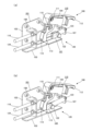
<座席装置10の概要>
図10は、座席装置10の脚台11、移動台20、および台枠30を示す斜視図である。図7は、座席装置10の内部構造を示す斜視図である。図5は、座席装置10のクロス状態を示す斜視図であり、図8は、座席装置10の同じくクロス状態を示す正面図である。図6は、座席装置10のロング状態を示す斜視図であり、図9は、座席装置10の同じくロング状態を示す側面図である。なお、各図において、同一部分についての多少の形状の違いは単に設計変更にすぎない(例えば図5および図10における脚台11の形状の違い等)。
<Overview of
FIG. 10 is a perspective view showing the
図10に示すように、座席装置10は、床面上に固定される脚台11と、脚台11に前後方向へ進退可能に支持された移動台20と、移動台20に正逆方向へ回転可能に支持された座席1の台枠30と、を備えている。ここで脚台11は、本発明の「座席の固定側」の一例であり、移動台20および台枠30は、本発明の「座席の可動側」の一例である。なお、座席装置10は、鉄道車両の客室内で壁(窓)際の床面上に配置され、図10中の「A」は、鉄道車両の進行方向と平行な壁の一部である。
As shown in FIG. 10, the
座席装置10では、座席1の台枠30は、回転機構40を介して、移動台20上で回転軸周りに回転可能に支持されている。また、移動台20は、スライド機構14を介して、脚台11上に回転機構40ごと進退可能に支持されている。さらに、座席装置10は、回転機構40による座席1の回転に、スライド機構14による座席1の進退を連動させるために、図示省略したが連動機構を備えている。
In the
<座席1について>
図5に示すように、座席1は、例えば2人掛け用の腰掛として、一対の座部2および背凭れ3を両側方向に並設してなる。座席1の両側には、座部2を側方から覆う一対の袖部4が設けられている。各袖部4の上端側は、略水平に前後に延びる肘掛5となっている。ここで肘掛5は、袖部4をなすフレーム材の上端面にクッション性のある肘当てを装着して構成されている。また、背凭れ3は、その下端側が座部2の後端側に、リクライニング機構50(図7参照)を介して傾倒可能に支持されている。
<About
As shown in FIG. 5, the
<リクライニング機構50>
図7に示すように、リクライニング機構50は、背凭れ3を座部2に対して所定の角度範囲で傾倒可能に支持するものである。リクライニング機構50は、例えばガススプリング等のダンパー51を備えている。ダンパー51は、シリンダ本体52に対してピストンロッド53が出没可能に挿入されて構成され、台枠30上で前後方向と平行に配置されている。ダンパー51は、ピストンロッド53がシリンダ本体52に収まる方向に付勢されているが、ピストンロッド53を任意の量だけ突出した状態に固定することができる。
<
As shown in FIG. 7, the
シリンダ本体52の後端は、背凭れ3内部のフレーム3aの下端に押し引き可能に連結されている。一方、シリンダ本体52の前端より出没するピストンロッド53の先端は、台枠30の前端側の適所に連結されている。このようなダンパー51によって、背凭れ3を任意の傾倒角度に保持することができる。すなわち、ダンパー51がロック状態のとき、シリンダ本体52よりピストンロッド53が所定量だけ突出した状態に固定され、背凭れ3を任意の傾倒角度に保持できるように構成されている。
The rear end of the
ダンパー51のロック状態を解除すると、シリンダ本体52にピストンロッド53が収まる付勢力によって、背凭れ3は最も起立した初期位置まで復帰する。かかるロック解除状態において、ダンパー51の復元力に抗して着座者が背凭れ3を後方へ押すことにより、背凭れ3を任意の傾倒角度に調整することができる。
When the
ダンパー51のロック機構は、一般的であるので詳細な説明は省略するが、ピストンロッド53の傍らに、ロック状態を解除するための解除ボタン54が設けられている。この解除ボタン54を押してロック状態を解除するためのリクライニング操作部100は、図7に示すように、前記肘掛5の前端に設けられている。なお、リクライニング操作部100は、本発明の「操作部」の一例である。
The locking mechanism of the
<リクライニング操作部100>
図1は、リクライニング操作部100の斜視図であり、同図(a)は、操作レバー110が拘束されていない状態(以下「非拘束状態」)を示し、同図(b)は、操作レバー110が拘束されている状態(以下「拘束状態」)を示している。図2は、リクライニング操作部100の側面図であり、同図(a)は、操作レバー110の非拘束状態を示し、同図(b)は、操作レバー110の拘束状態を示している。
<
FIG. 1 is a perspective view of the
図3は、リクライニング操作部100のうち一部(フランジ105)を切り欠いた斜視図であり、同図(a)は、操作レバー110の非拘束状態を示し、同図(b)は、操作レバー110の拘束状態を示している。図4は、リクライニング操作部100の操作レバー110を持ち上げた操作位置を示し、同図(a)は斜視図であり、同図(b)は側面図である。なお、図1から図4に示すように、リクライニング操作部100には、リクライニング操作ロック機構120が付設されている。
FIG. 3 is a perspective view with a part (flange 105) cut away of the
図1から図4に示すように、リクライニング操作部100は、一つのハウジング101に各部品が組み込まれてユニット化されており、図5に示すように、肘掛5(正確には袖部4の上端側)の前端内部に組み込まれている。リクライニング操作部100は、前記リクライニング機構50により背凭れ3を傾倒させる操作(リクライニング操作)を行うものである。ハウジング101は、図示したように前後方向に長い形状の金属製の部材であり、側面壁102の下端縁に沿って底面壁103が直角に折り曲げられている。
As shown in FIGS. 1 to 4, the
リクライニング操作部100は、ハウジング101に揺動可能に支持された操作レバー110を備えている。ハウジング101の側面壁102には、該側壁面102と平行な支持壁104が設けられている。操作レバー110は、支持壁104の後端側となるハウジング101全体の略中央に、水平面上を左右方向に延びる枢軸111を介して揺動可能に支持されている。
The
操作レバー110は、略L字形に形成されており、その略中間が枢支された枢軸111を揺動中心として、一端側は着座者が指で操作する操作部位112となっている。操作部位112は、座席1の前方へ向かって配されており、主として上下方向に揺動する。操作部位112に対して揺動中心を間にした他端側には、後述するストッパ121に係脱する当接部位113が設けられている。当接部位113は、下方へ向かって配されており、主として前後方向に揺動する。当接部位113の下方には、後述するリクライニングロックケーブル124の一端側が挿通する凹溝114が設けられている。
The operating
操作レバー110は、図2(a)に示すように、操作部位112が下方を向き、当接部位113が後方寄りとなる通常の初期位置から、図4(b)に示すように、リクライニング操作時に、操作部位112が上方に引かれて、当接部位113が前方寄りとなる操作位置に揺動(変位)するように設定されている。また、操作レバー110の揺動中心(枢軸111)と他端側(当接部位113)との間には、リクライニング操作ケーブル116の一端側を連結する掛止溝115が設けられている。
The operating
リクライニング操作ケーブル116の他端側は、図示省略したが前記リクライニング機構50の解除ボタン54側(図7参照)まで延ばされている。ここで操作レバー110を操作位置まで上方へ引くことにより、リクライニング操作ケーブル116を介して解除ボタン54側のリンク(図示せず)が引かれて解除ボタン54が押され、ダンパー51のロック状態が解除されるように構成されている。なお、操作レバー110は、通常はリクライニング操作ケーブル116に引かれて、初期位置に保持されている。
Although not shown, the other end of the
<リクライニング操作ロック機構120>
リクライニング操作部100には、該リクライニング操作部100を操作不能に拘束可能なリクライニング操作ロック機構120が付設されている。リクライニング操作ロック機構120は、座席1が後述するロング状態(特定の状態)にあるとき、リクライニング操作部100を操作不能に拘束するものである。なお、リクライニング操作ロック機構120は、本発明の「ロック機構」の一例である。
<Reclining
The
図1から図4に示すように、リクライニング操作ロック機構120は、リクライニング操作部100の操作レバー110が初期位置にあるときに、操作レバー110の当接部位113に対して係脱するストッパ121を有している。ストッパ121は、ハウジング101における底面壁103上の前方寄りの位置で、座席1の前後方向へ直線移動するように支持されている。
As shown in FIGS. 1 to 4, the reclining
ストッパ121は、例えば金属製のコマ状の部材からなり、底面壁103の前方寄りの位置で、側面壁102と平行に立ち上がるフランジ105に沿って、略水平面な底面壁103上を前後方向に直線移動するように支持されている。ここでフランジ105には、ストッパ121の側方に突設された軸122が移動可能に嵌合して案内されるガイド溝106が設けられている。なお、ストッパ121は、平面視において操作レバー110の操作部位112と当接部位113の間に位置している。
The
ストッパ121には、座席1が後述するロング状態(特定の状態)に変換されるときに引かれるリクライニングロックケーブル124の一端側が後方より連結されている。リクライニングロックケーブル124の一端側は、ストッパ121が直線移動する方向と同一方向に延びる直線状に配索されている。ここでリクライニングロックケーブル124の一端側は、操作レバー110の当接部位113にある凹溝114を挿通した状態で前方へ延び、当接部位113の先にあるストッパ121の後側に直接連結されている。
One end side of a
一方、リクライニングロックケーブル124の他端側は、後述する回転操作部200側まで延ばされている。リクライニングロックケーブル124は、座席1が特定の状態(後述するロング状態)にあるとき、回転操作部200側から引かれるように設定されている。ストッパ121は、リクライニングロックケーブル124に直接引かれることにより、操作レバー110の当接部位113から離脱した通常の非拘束位置(図1(a)参照)から前記当接部位113に係合する拘束位置(図1(b)参照)まで直線移動する。なお、リクライニングロックケーブル124は、本発明の「ケーブル」の一例である。
On the other hand, the other end side of the
ストッパ121の前側と、その前方に位置するハウジング101の前端片107との間には、バネ部材123が掛け渡されている。バネ部材123は、ストッパ121を通常の非拘束位置に付勢している。図1(a)に示すように、ストッパ121が非拘束位置、すなわち直線上の移動範囲の最前端にあるときは、操作レバー110の揺動を拘束することはなく、図4に示すように、操作レバー110の操作部位112を、上方の操作位置まで揺動させるリクライニング操作が可能となる。なお、バネ部材123は、本発明の「付勢手段」の一例である。
A
リクライニングロックケーブル124が引かれると、ストッパ121は、バネ部材123の付勢力に抗して、図1(b)に示すように、拘束位置、すなわち直線上の移動範囲の最後端まで後方へ直線移動する。これにより、ストッパ121の後端面が、操作レバー110の当接部位113に係合するため、操作レバー110は、通常の初期位置のままで操作部位112を上方へ揺動させることができず操作不能に拘束される。なお、ハウジング101の支持壁104は、操作レバー110の初期位置の位置決めをなしている。
When the
また、リクライニングロックケーブル124は、アウターケーブル内にインナーケーブルが摺動可能に内挿されてなり、アウターケーブルの端部は、ハウジング101の側面壁102の後端側に設けられたブラケット108に固定され、リクライニングロックケーブル124の一端側をなすインナーケーブルが、ブラケット108より先のストッパ121まで延びている。また、前記リクライニング操作ケーブル116も、同様にアウターケーブル内にインナーケーブルが摺動可能に内挿されてなり、アウターケーブルの端部はブラケット108に固定され、リクライニング操作ケーブル116の一端側をなすインナーケーブルが操作レバー110の掛止溝115まで延びている。
Further, the
<座席1の状態について>
図15は、座席1をロング状態、一クロス状態、逆クロス状態に変換する過程を示す説明図である。座席装置10は、座席1の状態を、座席背面が壁Aに略平行に沿うロング状態(図9,図6参照)と、座席背面が壁Aに略直交するクロス状態(図5参照)と、に変換可能である。ここでクロス状態には、一クロス状態(図5参照)と、一クロス状態に対して180度逆向きとなる逆クロス状態とがある。
<About the condition of
FIG. 15 is an explanatory diagram showing the process of converting the
図15に示すように、座席1のロング状態を原位置として回転角度を0°とすると、一クロス状態の回転角度は90°であり、逆クロス状態の回転角度は-90°である。なお、座席背面とは、背凭れ3の背面と同義である。以下、クロス状態と逆クロス状態とを総称するときは、単にクロス状態と表記する。
As shown in FIG. 15, if the long state of the
<脚台11>
図10に示すように、脚台11は、客室内で壁Aの傍らの床面上に固定されている。脚台11は、壁Aと略直交する方向(前後方向)に長い架台状にフレーム材を組み合わせて構成されている。脚台11の上面側は略水平であり、この上面側は、長辺をなす両側端部12,12と、後側(壁A側)の短辺をなす後端部とで囲まれているが、前側(通路側)は開放されている。
<Step stand 11>
As shown in FIG. 10, the
脚台11は、その後端部が壁Aと略平行に近接し、両側端部12,12が壁Aと略直交して通路側に向かうように配置されている。なお、脚台11の上面側には、次述するスライド機構14の他、台枠30の進退範囲や回転方向を規制するストッパ等の関連部品が設けられている。
The leg stand 11 is disposed such that its rear end is substantially parallel to and close to the wall A, and both end
<スライド機構14>
図10に示すように、脚台11の上面側には、スライド機構14を介して移動台20が、壁Aと略直交する方向へ進退可能に取り付けられている。スライド機構14は、脚台11の両側端部12,12の内側に設けられた一対のガイドレール14a,14aを備えている。一対のガイドレール14a,14aは、脚台11の両側端部12,12の内側に沿って互いに平行に対向しており、各ガイドレール14aの内側に、次述する移動台20の両側部21,21がそのまま摺動可能に嵌合している。
<Slide mechanism 14>
As shown in FIG. 10, a movable table 20 is attached to the upper surface side of the leg stand 11 via a slide mechanism 14 so as to be movable in a direction substantially perpendicular to the wall A. The slide mechanism 14 includes a pair of
<移動台20>
図10に示すように、移動台20は、脚台11の上面側で略水平に配置されており、長方形の枠組状にフレーム材を組み合わせて構成されている。移動台20の長辺をなす両側端部21,21は、前述した一対のガイドレール14a,14aの内側に摺動可能に嵌合している。よって、移動台20は、壁Aに対して略直交する方向に前進ないし後退するようにスライド可能となっている。移動台20の略中央には、座席1を回転軸周りに回転させる回転機構40が設けられている。
<Moving table 20>
As shown in FIG. 10, the movable table 20 is arranged substantially horizontally on the upper surface side of the
<回転機構40>
回転機構40は、移動台20上に座席1の台枠30を略水平面上で正逆方向へ回転可能に支持するものである。回転機構40は、例えば内外一対のリング状の回転盤が、その間にベアリング等を介在させて、互いに回転可能に組み合わされたユニットとして構成されている。かかる回転機構40では、外側の回転盤が移動台20に固定され、内側の回転盤が台枠30に固定される。
<
The
座席1の回転中心となる回転軸は、回転機構40の中心線であり、本実施形態では物理的な実態を伴うものではない。図8に示すように、回転機構40は、動力源であるモータ41を備えている。モータ41には減速機が付設されており、その出力軸にある駆動ギヤが、台枠30側に設けられた回転軸を中心とするスプロケット42に回転可能に噛み合わされている。なお、回転機構40は、手動によっても座席を回転可能となっている。
The rotation axis, which is the center of rotation of the
<台枠30>
図10に示すように、台枠30は、座席1を取り付けて移動台20上の回転機構40に支持するものである。台枠30は、例えば座部2の底面に合致する金属板により構成されている。台枠30の下面側には、前述したがモータ41の駆動ギヤが回転可能に噛み合うスプロケット42が一体に設けられている。
<
As shown in FIG. 10, the
<連動機構>
また、座席装置10は、座席1をロング状態、一クロス状態、逆クロス状態に変換するとき、座席1が壁Aと干渉しないように、座席1の回転と進退を連動させる連動機構(図示せず)を備えている。なお、ロング状態が、本発明の「座席1の特定の状態」に相当する。
<Interlocking mechanism>
The
連動機構は、座席1を台枠30と共に回転させたとき、該台枠30の回転を直線運動に変換して移動台20に伝達し、移動台20を台枠30と共に、壁Aに対して近接ないし離隔するように直線方向へ進退させる。このような連動機構の種類は、特に限定されるものではないが、具体的には例えば、本出願人が既に提案している特開2018-187971号公報に記載された発明、あるいは未公開であるが特願2019-239066号で提案した発明等を利用すると良い。
When the
<回転ロック機構60>
図13は、回転ロック機構60を示す斜視図である。図14は、回転ロック機構60を下側から見た状態を示す斜視図である。
図10に示すように、座席装置10は、台枠30(座席)をロング状態、一クロス状態、逆クロス状態のそれぞれの回転位置で回転不能に拘束する回転ロック機構60を備えている。回転ロック機構60は、台枠30を脚台11に対して回転不能にロックするため、必然的に移動台20も脚台11に対して進退不能に拘束される。
<
FIG. 13 is a perspective view showing the
As shown in FIG. 10, the
回転ロック機構60は、脚台11側から台枠30に亘り上下に出没可能なロックピン61と、台枠30に設けられ前記ロックピン61が係脱する係止孔62a,62b,62cとを備えている。各係止孔62a,62b,62cは、略長方形の台枠30のうち、座席背面に沿う一長辺側と、座席両側に沿う両短辺側に、それぞれ合計3つ設けられている。
The
ロックピン61は、ユニット60aに組み込まれており、ユニット60aは、脚台11の上面側の後端寄りに固定されている。ロックピン61は、脚台11の上面側より上方へ出没可能であり、上方へ突出して係止孔62a,62b,62cに嵌入するロック位置と、下方へ没入して係止孔62a,62b,62cから外れるロック解除位置と、に動作する。
The
ロックピン61は、座席1がロング状態、一クロス状態、逆クロス状態に変換されたとき、それぞれの位置で上下に合致する台枠30側の係止孔62a,62b,62cに嵌入することで、座席1を回転不能に拘束する。すなわち、ロング状態のとき、ロックピン61は、台枠30の一長辺側にある係止孔62aに嵌入する。また、一クロス状態のとき、ロックピン61は、台枠30の一短辺側にある係止孔62bに挿入されて係合する。さらに、逆クロス状態のとき、ロックピン61は、台枠30の他短辺側にある係止孔62cに嵌入する。
The
図13,図14に示すように、ロックピン61が組み込まれたユニット60aには、ロックピン61を上方へ突出させロック位置に常時付勢するバネ部材(図示せず)と、ロックピン61をバネ部材の付勢力に抗して下方のロック解除位置に没入させるリンク60bとが、それぞれ設けられている。ここでリンク60bには、足踏操作用の回転操作ケーブル206(図11参照)の一端側が連結されている。
As shown in FIGS. 13 and 14, the
ロックピン61は、バネ部材の付勢力によって通常はロック位置に維持されるが、リンク60bが回転操作ケーブル206によって引かれると、バネ部材の付勢力に抗してロック解除位置に没入するように構成されている。図11に示すように、回転操作ケーブル206の他端側は、脚台11側に設けられた後述の回転操作部200まで延ばされている。ここで回転操作部200における操作によって回転操作ケーブル206が引っ張られ、回転ロック機構60の拘束が解除されるように構成されている。
The
また、回転ロック機構60のリンク60bには、図示省略したが電動操作用の回転操作ケーブルの一端側も連結されている。電動操作用の回転操作ケーブルを引っ張る動力源は、例えば回転機構40のモータ41が兼用されている。すなわち、モータ41はクラッチを備えており、クラッチの切り替えにより、回転機構40により座席を回転させる動作と、ロックピン61を没入させてロック解除する動作と、に切り替え可能に構成されている。なお、モータ41のクラッチに関する構成は、一般的であるので詳細な説明は省略する。
Further, although not shown, one end side of a rotation operation cable for electric operation is also connected to the
本実施形態に係る回転ロック機構60では、座席1がロング状態にあるときは、回転ロック機構60による拘束を、回転操作部200における足踏操作では解除できず、モータ41による電動操作のみで解除することができるように構成されている。ここで電動操作は、車両の乗務員や駅員によって行われるものであり、足踏操作は主に乗客によって行われる。
In the
<回転操作部200>
図11は、回転操作部200が回転操作阻止機構210により操作不能に拘束されていない状態を示す側面図である。図12は、回転操作部200が回転操作阻止機構210により操作不能に拘束された状態を示す側面図である。
図5に示すように、回転操作部200は、一つのハウジング201に各部品が組み込まれてユニット化されており、移動台20の前端側より垂下する状態に固定されている。
<
FIG. 11 is a side view showing a state in which the
As shown in FIG. 5, the
図11に示すように、回転操作部200は、ハウジング201の内側に固定された支持ブラケット202の下端に、枢軸203を介して揺動可能に支持された足踏ペダル204を備えている。足踏ペダル204は、その基端側が枢支された枢軸203を回転中心として、先端側が前後方向へ揺動可能である。
As shown in FIG. 11, the
足踏ペダル204は、先端側がハウジング201の前方へ突出する使用位置(図11参照)と、先端側が上方へ引っ込む収納位置(図12参照)と、に揺動する。足踏ペダル204は、バネ部材205を介して通常は前方へ突出する使用位置に付勢されている。ここで足踏ペダル204が使用位置にあるとき、これを踏み込んで回転ロック機構60による拘束を解除する操作が可能であるが、足踏ペダル204が収納位置にあるときは、回転ロック機構60による拘束を解除する操作は不能となる。
The
足踏ペダル204の基端側には、前記回転ロック機構60側まで延ばされた足踏操作用の回転操作ケーブル206の他端側がコネクタを介して連結されている。ここで使用位置にある足踏ペダル204を下方へ踏み込むと、回転操作ケーブル206が引かれてロックピン61(図13参照)が下方へ没入し、回転ロック機構60のロック状態が解除されるように構成されている。
The other end side of a
また、足踏ペダル204の基端側には、枢軸203から偏心した位置で両側方向へ突出したピン状の被係合部207が固定されている。被係合部207には、前記リクライニング操作ロック機構120側から延ばされたリクライニングロックケーブル124の他端側がコネクタを介して連結されている。ここで被係合部207が次述する係合部211に係合すると、リクライニングロックケーブル124が引かれてリクライニング操作ロック機構120のストッパ121が後方へ移動し、リクライニング操作部100を操作不能に拘束するように構成されている。
Furthermore, a pin-shaped engaged
<回転操作阻止機構210>
また、回転操作部200には、該回転操作部200による拘束の解除操作を不能とする回転操作阻止機構210が付設されている。回転操作阻止機構210は、座席1がロング状態にあるとき、足踏ペダル204の操作を不能とするものである。ここでロング状態が、本発明における「座席1が特定の状態」に相当する。
<Rotation
Further, the
図11,図12に示すように、回転操作阻止機構210は、座席1の固定側である脚台11に設けられた係合部211と、座席1の可動側にある前記回転操作部200に設けられた被係合部207と、を備えている。係合部211は、脚台11のうち下面側の前端に配置され、例えば前方へ向かって斜め上方へ突出する金属製のブラケット状に形成されている。
As shown in FIGS. 11 and 12, the rotational
被係合部207は、前述したように足踏ペダル204の基端側で枢軸203から偏心した位置に金属製のピン状に設けられている。被係合部207は、座席1がロング状態(特定の状態)にあるとき、ちょうど係合部211に係合するように設定されている。被係合部207が係合部211に係合すると、足踏ペダル204をバネ部材205の付勢力に抗して収納位置に揺動させるため、回転操作部200における解除操作を不能とする。同時に、リクライニング操作部100を操作不能に拘束する。
As described above, the engaged
<座席装置10の作用>
以下、本実施形態に係る座席装置10の作用を説明する。
図15に基づいて、先ず、座席1の状態を変換する動作について説明する。図15(a)に示すように、台枠30(座席1)がロング状態にあるとき、台枠30の回転軸(回転機構40)は、壁A側に最も後退(接近)している。台枠30の長辺(座席背面)は、壁Aに略平行に沿って回転角度は0°となっている。このとき、図10に示すように、回転ロック機構60のロックピン61は、台枠30の一長辺側にある係止孔62aに嵌入しており、台枠30(座席1)は、ロング状態で回転不能に拘束される。
<Function of
Hereinafter, the operation of the
First, the operation of converting the state of the
<<ロング状態から一クロス状態の変換>>
図15(a)から図15(c)に示すように、台枠30(座席1)をロング状態から一クロス状態(回転角度90°)に変換するには、回転ロック機構60による回転の拘束を解除する必要がある。ロックピン61を係止孔62aから外す動作は、足踏ペダル204の操作では行うことはできず、モータ41の動力を利用した電動操作によって行われる。
<<Conversion from long state to one cross state>>
As shown in FIGS. 15(a) to 15(c), in order to convert the underframe 30 (seat 1) from the long state to the one-cross state (rotation angle of 90°), rotation is restricted by the
図15(a)に示すロング状態において、回転ロック機構60による拘束を解除した後、図15(b)に示すように、台枠30を正方向(図15中で反時計回り)へモータ41で回転させると、台枠30は連動機構によって前進しながら回転する。すなわち、台枠30は、壁Aと干渉しないように、正方向へ回転しながら通路側へ前進しつつ回転する。
In the long state shown in FIG. 15(a), after releasing the restraint by the
図15(c)に示すように、台枠30が一クロス状態(回転角度90°)に到達すると、図10において、回転ロック機構60のロックピン61が、台枠30の一短辺側にある係止孔62bに嵌入する。これにより、台枠30(座席1)は、一クロス状態で回転不能に拘束される。
As shown in FIG. 15(c), when the
<<一クロス状態から逆クロス状態の変換>>
図15(c)に示す一クロス状態おいて、回転ロック機構60の拘束を解除した後、台枠30を逆方向(図15中で時計回り)へ回転させると、台枠30は連動機構によって、例えば回転しながら後退ないし前進する。続いて、図15(d)に示すように、台枠30は、ロング状態と平行な状態で前進した位置に一旦保持された状態で、そのまま進退はせずに逆方向へそのまま回転する。
<<Conversion from one cross state to reverse cross state>>
In the cross state shown in FIG. 15(c), when the
図15(e)に示すように、台枠30が逆クロス状態(回転角度-90°)に到達すると、回転ロック機構60のロックピン61が、台枠30の他方の短辺側の係止孔62cに嵌入し、再び台枠30は回転不能に拘束される。このような座席1の一クロス状態から逆クロス状態への変換は、足踏ペダルの足踏操作に限らず、モータ41の電動操作によっても行うことができる。なお、座席1を、逆クロス状態から一クロス状態、さらに一クロス状態から元のロング状態に戻すには、前述したロング状態から一クロス状態、および一クロス状態から逆クロス状態への変換と、それぞれ逆の動作を行えば良い。
As shown in FIG. 15(e), when the
<<背凭れ3のリクライニング操作の拘束>>
座席1がロング状態にあるとき、リクライニング操作ロック機構120により、リクライニング操作部100におけるリクライニング操作は不能となる。すなわち、座席1がロング状態へ変換されるとき、図12に示すように、脚台11にある係合部211に対して被係合部207が係合して変位する。ここで被係合部207は、枢軸203を回転中心として足踏ペダル204を上方へ揺動させる方向へ変位する。被係合部207の変位に伴って、被係合部207に連結されているリクライニングロックケーブル124が引かれる。
<<Restrictions on reclining operation of
When the
図1(a)において、リクライニングロックケーブル124が引かれると、ストッパ121は、操作レバー110の当接部位113から離脱していた非拘束位置からバネ部材123の付勢力に抗して、図1(b)に示すように、当接部位113に係合する拘束位置まで直線移動する。これにより、操作レバー110は、通常の初期位置のままで操作部位112を上方へ揺動させることができず操作不能に拘束され、リクライニング機構50によって背凭れ3を傾倒させることはできない。
In FIG. 1(a), when the
このようなリクライニング操作ロック機構120により、ロング状態では、着座者による背凭れ3のリクライニング操作を確実に阻止することができ、背凭れ3が不用意に傾倒して壁Aと干渉することを防ぐことができる。リクライニング操作ロック機構120は、リクライニングロックケーブル124によって直接引かれるストッパ121だけで足り、ストッパ121を直線移動させるリンク等の特別な機構は不要となる。
Such a reclining
従って、リクライニング操作ロック機構120の部品点数が削減されて構成も簡易化かつ小型化され、コストダウンおよび配置スペースの削減が可能となる。また、ストッパ121は、リンク等の他の部材を介してリクライニングロックケーブル124により間接的に引かれるものではなく、リクライニングロックケーブル124に直接連結されて直に引かれる。そのため、リクライニングロックケーブル124以外の他の部材の劣化により引きが不十分となる虞はなく、確実に移動させることができる。
Therefore, the number of parts of the reclining
しかも、ストッパ121は、ハウジング101の略水平な底面壁103上を前後方向に直線移動する。また、ストッパ121に直接連結されたリクライニングロックケーブル124も、ストッパ121が直線移動する同一水平面上で同一方向に直線状に延びている。従って、リクライニング操作ロック機構120では、上下方向に嵩張る構成や動作はなく、高さ寸法を大幅に抑えることができる。そのため、袖部4の上端側には、リクライニング操作ロック機構120の上下方向の寸法を小さくした分だけ、厚みのある肘掛5を付加することが可能となる。
Furthermore, the
<<背凭れ3のリクライニング操作の拘束解除>>
座席1がクロス状態に変換されると、リクライニング操作ロック機構120によるリクライニング操作部100の操作不能な拘束が解除される。すなわち、座席1のクロス状態では、図11に示すように、脚台11にある係合部211に対して、移動台20にある足踏ペダル204の被係合部207は係合せずに離れる。よって、足踏ペダル204は、バネ部材205の付勢力により前方へ突出した使用位置となり、リクライニングロックケーブル124は引かれない状態となる。
<<Release of restraint on reclining operation of
When the
すると、図1(a)に示すように、リクライニング操作ロック機構120では、ストッパ121がバネ部材123の付勢力により、操作レバー110の当接部位113から離脱する非拘束位置まで前方へ直線移動する。これにより、操作レバー110の操作不能な拘束は解除されて、リクライニング操作が可能となる。すなわち、着座者は、図4に示すように、操作レバー110の操作部位112を上方へ揺動させるリクライニング操作が可能となり、背凭れ3を任意の角度に傾倒させることができ、座り心地を良くすることができる。
Then, as shown in FIG. 1(a), in the reclining
なお、操作レバー110の操作部位112が上方の操作位置まで揺動すると、当接部位113の凹溝114を通るリクライニングロックケーブル124の途中が下方へ押される。このリクライニングロックケーブル124の変位は、リクライニングロックケーブル124の遊びで吸収される範囲内に設定されている。従って、リクライニングロックケーブル124の先にある回転操作部200側の動作に影響を及ぼすことはない。
Note that when the operating
<<座席1の回転操作の拘束>>
図10に示すように、座席1がロング状態にあるとき、回転ロック機構60により、台枠30は、移動台20に対して回転不能に拘束される。すなわち、回転ロック機構60のロックピン61が、台枠30の一長辺側にある係止孔62aに嵌入している。ここでロックピン61は、座席1の固定側である脚台11から突出するため、座席1は回転不能のみならず、同時に進退不能に拘束されている。
<<Restriction on rotating operation of
As shown in FIG. 10, when the
図6に示すように、座席1がロング状態にあるとき、回転操作阻止機構210により、回転操作部200における解除操作は不能となる。すなわち、ロング状態では、移動台20が壁A側に最も後退(接近)しており、移動台20の前端側は脚台11の前端側に重なる。かかる位置関係により、図12に示すように、脚台11にある係合部211に対して、移動台20にある足踏ペダル204の被係合部207が係合する。すると、足踏ペダル204は、バネ部材205の付勢力に抗して起立した収納位置に揺動し、当該収納位置に拘束される。
As shown in FIG. 6, when the
これにより、座席1がロング状態にあるとき、足踏ペダル204は、単に操作不能な収納位置に変位するだけでなく、係合部211と被係合部207との係合関係によって、収納位置に強固に保持される。従って、ロング状態では、回転操作部200における解除操作が不能となる。このような簡易な構成により、ロング状態では、着座者による座席1の回転操作を確実に阻止することができる。
As a result, when the
<<座席1の回転操作の拘束解除>>
座席1がクロス状態にあるときは、回転操作阻止機構210による回転操作部200の操作不能な拘束も解除される。すなわち、図15(c)に示すクロス状態では、移動台20が壁A側から最も前進(離隔)しており、移動台20の前端側は脚台11の前端側より前方に離れて位置する。かかる位置関係では、図11に示すように、脚台11にある係合部211に対して、移動台20にある足踏ペダル204の被係合部207は係合せずに離れる。よって、足踏ペダル204は、バネ部材205の付勢力により前方へ突出した使用位置となる。
<<Release of restriction on rotation operation of
When the
このとき、座席1の着座者は、足踏ペダル204を踏み込むことにより、回転ロック機構60による拘束を解除することができる。すなわち、図11において、足踏ペダル204が踏み込まれて下方へ揺動すると、回転操作ケーブル206が引かれてロックピン61(図13参照)が下方へ没入し、回転ロック機構60のロック状態が解除される。これにより、着座者は座席1を手動で回転させることができる。
At this time, the person sitting on the
<本発明の構成と作用効果>
以上、本発明の実施形態について説明したが、本発明は前述した実施形態に限定されるものではない。前述した実施形態から導かれる本発明について、以下に説明する。
<Configuration and effects of the present invention>
Although the embodiments of the present invention have been described above, the present invention is not limited to the embodiments described above. The present invention derived from the embodiments described above will be described below.
先ず、本発明は、
座席1の状態を変換可能な座席装置10において、
座席1の背凭れ3を傾倒可能なリクライニング機構50と、
前記リクライニング機構50により背凭れ3を傾倒させる操作を行う操作部100と、
座席1が特定の状態にあるとき、前記操作部100を操作不能に拘束するロック機構120と、
座席1の前記特定の状態への変換に伴い引かれるケーブル124と、を備え、
前記操作部100は、通常の初期位置から操作時の操作位置に変位可能であり、
前記ロック機構120は、前記初期位置にある操作部100に対して直線移動により係脱するストッパ121を有し、
前記ストッパ121は、前記ケーブル124に直接引かれて、前記操作部100から離脱した通常の非拘束位置から前記操作部100に係合して操作不能とする拘束位置まで直線移動することを特徴とする。
First, the present invention
In the
a
an
a
A
The
The
The
このようなロック機構120では、ストッパ121がケーブル124に直接引かれて、リクライニング機構50の操作部100に係合して操作不能とする拘束位置まで直線移動する。そのため、ストッパ121を移動させるためのリンク等の特別な機構は不要となり、部品点数が削減されて構成も簡易化かつ小型化され、コストダウンおよび配置スペースの削減が可能となる。
In such a
しかも、ストッパ121は、リンク等の他の部材を介してケーブル124により間接的に引かれるものではなく、ケーブル124に直接連結されて直に引かれる。そのため、ケーブル124以外の他の部材の劣化により引きが不十分となる虞はなく、確実に移動させることができる。
Furthermore, the
また、本発明として、
前記ストッパ121は、略水平面上を座席1の前後方向に直線移動する状態に支持されたことを特徴とする。
Moreover, as the present invention,
The
これにより、リクライニング操作ロック機構120では、上下方向に嵩張る構成や動作はなく、高さ寸法をよりコンパクトに構成することが可能となる。従って、リクライニング操作ロック機構120を取り付ける例えば袖部4(肘掛5)等の配置スペースにおいて、いっそう省スペース化の要請に応じることができ、設計上の自由度も高めることができる。
As a result, the reclining
また、本発明として、
前記ストッパ121は、付勢手段123により通常は前記非拘束位置に保持される一方、前記ケーブル124により引かれると、前記付勢手段123の付勢力に抗して前記拘束位置に直線移動し、かつ当該拘束位置に保持されることを特徴とする。
Moreover, as the present invention,
The
このように、ストッパ121を、付勢手段123の付勢力で非拘束位置に保持することにより、動力を用いることなく簡易な構成で容易に非拘束位置に維持することができる。また、ストッパ121を、ケーブル124により引くだけで、付勢手段123の付勢力に抗して拘束位置まで容易に直線移動させて、当該拘束位置に確実に保持することができる。
In this manner, by holding the
また、本発明として、
前記操作部100は、座席1にある肘掛5の前端側で、前記初期位置と前記操作位置とに揺動可能に支持された操作レバー110を備え、
前記操作レバー110は、操作する一端側に対して揺動中心を間にした他端側に、前記ストッパ121に係脱する当接部位113が設けられ、
前記ケーブル124は、一端側の直線部分が前記操作レバー110の当接部位113を貫通した状態で配索され、前記当接部位113の先に配置された前記ストッパ121に直接連結されたことを特徴とする。
Moreover, as the present invention,
The
The
The
このように、リクライニング機構50の操作部100は、座席1にある肘掛5の前端側に操作レバー110を備えることで、着座者は着座した姿勢のまま容易に操作することが可能となる。操作レバー110は、その揺動中心を間にして、一端側が操作する部位(操作部位112)となり、他端側がストッパ121に係脱する当接部位113となる。前記ケーブル124は、操作レバー110の当接部位113(の凹溝114)を貫通した状態で配索され、当接部位113の先にあるストッパ121に直接連結される。
In this manner, the
かかる構成により、ストッパ121は、操作レバー110の一端側と他端側との間に配置されると共に、ケーブル124は、操作レバー110の他端側と重なるように配置される。そのため、操作部100とロック機構120とを、全体的にいっそうコンパクトに構成することが可能となる。ここでストッパ121が引かれる方向と、ストッパ121が直線移動する方向とを一致させることにより、ストッパ121を小さな力で確実に移動させることも可能となる。
With this configuration, the
また、本発明として、
座席1を回転軸周りに回転させる回転機構40と、
座席1を固定側より前記回転機構40ごと進退させるスライド機構14と、を有し、
前記回転機構40および前記スライド機構14の連動によって座席1の状態は、
座席1背面が壁に略平行に沿うロング状態と、
前記ロング状態と略直交する向きで壁から離れたクロス状態と、に変換可能であり、
座席1の前記特定の状態は、前記ロング状態であることを特徴とする。
Moreover, as the present invention,
a
a slide mechanism 14 for moving the
Due to the interlocking movement of the
a long state in which the back of
The long state can be converted into a cross state in which the state is away from the wall in a direction substantially perpendicular to the long state,
The specific state of the
これにより、本座席装置10を、前述した実施形態に記載したとおり、鉄道車両に搭載される一般的な腰掛タイプの回転座席に、そのまま適用することが可能となる。そして、座席1がロング状態にあるとき、背凭れ3の背面が壁Aと略平行に近接するため、前述したように、ロック機構120によって、リクライニング機構50の操作部100を操作不能に拘束する必要がある。
As a result, the
さらに、本発明として、
座席1の固定側である脚台11と、
前記脚台11に前記スライド機構14を介して進退可能に支持され、前記回転機構40を介して座席1が回転可能に支持された移動台20と、
前記脚台11に設けられた係合部211と、
前記移動台20に設けられ、座席1が前記ロング状態のとき、前記係合部211に係合して変位する被係合部207と、を有し、
前記被係合部207と前記ストッパ121とは、前記ケーブル124により連結され、前記被係合部207の変位に基づき前記ケーブル124が引かれることを特徴とする。
Furthermore, as the present invention,
A
a
an engaging
an engaged
The engaged
このように、本座席装置10によれば、係合部211と被係合部207との機械的な係合関係に起因して、ケーブル124を介してストッパ121を移動させることが可能である。このような簡易な構成で電動力を用いることもなく、座席1の特定の状態であるロング状態のときだけ、リクライニング操作を規制することができる。
In this way, according to the
<別の本発明の構成と作用効果>
また、前述した実施形態からは、次の別発明も導かれる。
座席1は回転軸周りに回転可能であり、該座席1を複数ある回転角度ごとに拘束可能な回転ロック機構60と、
前記回転ロック機構60による拘束の解除操作を行う回転操作部200と、
座席1が一の回転角度の特定の状態にあるとき、前記回転操作部200における解除操作を不能とする回転操作阻止機構210と、を備え、
前記回転操作阻止機構210は、
座席1の固定側に設けられた係合部211と、
座席1の可動側で前記回転操作部200に設けられ、座席1が前記特定の状態にあるとき、前記係合部211に係合することにより、前記回転操作部200における解除操作を不能とする被係合部207と、を備えることを特徴とする。
<Another structure and effects of the present invention>
Moreover, the following other invention can also be derived from the above-described embodiment.
The
a
a rotational
The rotational
An engaging
Provided on the
本座席装置10では、座席1が特定の状態であるロング状態にあるとき、座席背面は壁Aに近接するが、乗客が勝手にポジションを変えられないように、着座者による座席1の回転を不能とする。ここで座席1の回転には、回転操作部200によって、回転ロック機構60による拘束を解除する必要がある。そこで、回転操作阻止機構210により、回転操作部200の操作を不能とすることで、座席1の回転を不能とすることができる。
In this
回転操作阻止機構210では、座席1がロング状態にあるとき、座席1の固定側にある係合部211に対して、座席1の可動側で回転操作部200にある被係合部207が係合することにより、回転操作部200の解除操作を不能とする。このような係合部211と被係合部207との機械的な係合関係により、簡易な構成で電動力を用いることもなく、座席1がロング状態のときだけ、着座者による座席1の回転を不能とすることができる。
In the rotation
以上、実施形態を図面によって説明してきたが、具体的な構成はこれらの実施形態に限られるものではなく、本発明の要旨を逸脱しない範囲における変更や追加があっても本発明に含まれる。例えば、座席1は2人掛けの例を説明したが、3人掛けや1人掛けの座席であっても良い。
Although the embodiments have been described above with reference to the drawings, the specific configurations are not limited to these embodiments, and any changes or additions that do not depart from the gist of the present invention are included in the present invention. For example, although the
また、リクライニング操作部100の操作レバー110や、リクライニング操作ロック機構120のストッパ121の具体的な形状は、図示したものに限定されることはない。また、脚台11、移動台20、台枠30の具体的な形状も、図示したものに限定されることはない。さらに、座席の状態の変換は、ロング状態、一クロス状態、逆クロス状態に限定されるものではない。
Further, the specific shapes of the
本発明は、鉄道車両、航空機、自動車、船舶等の客室内に設置される乗物用の座席の他、劇場用、家庭用、事務用の椅子を対象とした座席装置として広く利用することができる。 INDUSTRIAL APPLICABILITY The present invention can be widely used as a seat device for seats for vehicles installed in passenger cabins of railway vehicles, aircraft, automobiles, ships, etc., as well as chairs for theaters, homes, and offices. .
10…座席装置
11…脚台
14…スライド機構
20…移動台
30…台枠
40…回転機構
50…リクライニング機構
60…回転ロック機構
100…リクライニング操作部
110…操作レバー
111…枢軸
112…操作部位
113…当接部位
116…リクライニング操作ケーブル
120…リクライニング操作ロック機構
121…ストッパ
122…軸
123…バネ部材
124…リクライニングロックケーブル
200…回転操作部
204…足踏ペダル
207…被係合部
210…回転操作阻止機構
211…係合部
DESCRIPTION OF
Claims (5)
座席の背凭れを傾倒可能なリクライニング機構と、
前記リクライニング機構により背凭れを傾倒させる操作を行う操作部と、
座席が特定の状態にあるとき、前記操作部を操作不能に拘束するロック機構と、
座席の前記特定の状態への変換に伴い引かれるケーブルと、を備え、
前記操作部は、通常の初期位置から操作時の操作位置に変位可能であり、
前記ロック機構は、前記初期位置にある操作部に対して直線移動により係脱するストッパを有し、
前記ストッパは、前記ケーブルに直接引かれて、前記操作部から離脱した通常の非拘束位置から前記操作部に係合して操作不能とする拘束位置まで直線移動するものであり、
前記操作部は、座席にある肘掛の前端側で、前記初期位置と前記操作位置とに揺動可能に支持された操作レバーを備え、
前記操作レバーは、操作する一端側に対して揺動中心を間にした他端側に、前記ストッパに係脱する当接部位が設けられ、
前記ケーブルは、一端側の直線部分が前記操作レバーの当接部位を貫通した状態で配索され、前記当接部位の先に配置された前記ストッパに直接連結されたことを特徴とする座席装置。 In a seat device that can change the state of the seat,
A reclining mechanism that allows the seat back to be tilted,
an operation unit that performs an operation for tilting the backrest using the reclining mechanism;
a locking mechanism that locks the operating section so that it cannot be operated when the seat is in a specific state;
a cable that is pulled when the seat is converted to the specific state;
The operating unit is movable from a normal initial position to an operating position during operation,
The locking mechanism has a stopper that engages and disengages from the operation part in the initial position by linear movement,
The stopper is directly pulled by the cable and moves in a straight line from a normal unrestricted position where the stopper separates from the operating part to a restrained position where it engages with the operating part and makes it inoperable;
The operating unit includes an operating lever supported swingably between the initial position and the operating position on the front end side of an armrest on the seat;
The operating lever is provided with an abutment portion that engages and disengages from the stopper at the other end side with the pivot center in between with respect to the one end side to be operated,
The seat device is characterized in that the cable is routed such that one end of the cable passes through the abutment area of the operating lever, and is directly connected to the stopper disposed ahead of the abutment area. .
座席を固定側より前記回転機構ごと進退させるスライド機構と、を有し、
前記回転機構および前記スライド機構の連動によって座席の状態は、
座席背面が壁に略平行に沿うロング状態と、
前記ロング状態と略直交する向きで壁から離れたクロス状態と、に変換可能であり、
座席の前記特定の状態は、前記ロング状態であることを特徴とする請求項1,2または3に記載の座席装置。 a rotation mechanism that rotates the seat around a rotation axis;
a slide mechanism for moving the seat forward and backward along with the rotation mechanism from the fixed side;
The state of the seat is determined by the interlocking of the rotation mechanism and the slide mechanism.
A long state where the back of the seat is approximately parallel to the wall,
The long state can be converted into a cross state in which the state is away from the wall in a direction substantially perpendicular to the long state,
The seat device according to claim 1, 2 or 3 , wherein the specific state of the seat is the long state.
前記脚台に前記スライド機構を介して進退可能に支持され、前記回転機構を介して座席が回転可能に支持された移動台と、
前記脚台に設けられた係合部と、
前記移動台に設けられ、座席が前記ロング状態のとき、前記係合部に係合して変位する被係合部と、を有し、
前記被係合部と前記ストッパとは、前記ケーブルにより連結され、前記被係合部の変位に基づき前記ケーブルが引かれることを特徴とする請求項4に記載の座席装置。 A legrest, which is the fixed side of the seat,
a movable platform supported by the leg base so as to be movable forward and backward via the slide mechanism, and a seat rotatably supported via the rotation mechanism;
an engaging part provided on the leg base;
an engaged part that is provided on the movable platform and that engages with and is displaced by the engaging part when the seat is in the long state;
The seat device according to claim 4 , wherein the engaged portion and the stopper are connected by the cable, and the cable is pulled based on displacement of the engaged portion.
Priority Applications (4)
| Application Number | Priority Date | Filing Date | Title |
|---|---|---|---|
| JP2020198656A JP7361676B2 (en) | 2020-11-30 | 2020-11-30 | seat equipment |
| US18/254,873 US20230415619A1 (en) | 2020-11-30 | 2021-11-10 | Seat device |
| CN202180079875.3A CN116546905A (en) | 2020-11-30 | 2021-11-10 | Seating arrangement |
| PCT/JP2021/041297 WO2022113737A1 (en) | 2020-11-30 | 2021-11-10 | Seat device |
Applications Claiming Priority (1)
| Application Number | Priority Date | Filing Date | Title |
|---|---|---|---|
| JP2020198656A JP7361676B2 (en) | 2020-11-30 | 2020-11-30 | seat equipment |
Publications (2)
| Publication Number | Publication Date |
|---|---|
| JP2022086572A JP2022086572A (en) | 2022-06-09 |
| JP7361676B2 true JP7361676B2 (en) | 2023-10-16 |
Family
ID=81755902
Family Applications (1)
| Application Number | Title | Priority Date | Filing Date |
|---|---|---|---|
| JP2020198656A Active JP7361676B2 (en) | 2020-11-30 | 2020-11-30 | seat equipment |
Country Status (4)
| Country | Link |
|---|---|
| US (1) | US20230415619A1 (en) |
| JP (1) | JP7361676B2 (en) |
| CN (1) | CN116546905A (en) |
| WO (1) | WO2022113737A1 (en) |
Families Citing this family (1)
| Publication number | Priority date | Publication date | Assignee | Title |
|---|---|---|---|---|
| WO2024010013A1 (en) * | 2022-07-06 | 2024-01-11 | テイ・エス テック株式会社 | Rotation device and method for manufacturing same |
Citations (3)
| Publication number | Priority date | Publication date | Assignee | Title |
|---|---|---|---|---|
| JP2002301955A (en) | 2001-04-03 | 2002-10-15 | T S Tec Kk | Seat for vehicle |
| JP2016159735A (en) | 2015-02-27 | 2016-09-05 | 株式会社今仙電機製作所 | Link mechanism |
| JP2017094958A (en) | 2015-11-25 | 2017-06-01 | コイト電工株式会社 | Seat support mechanism |
Family Cites Families (1)
| Publication number | Priority date | Publication date | Assignee | Title |
|---|---|---|---|---|
| JPS58188334U (en) * | 1982-06-11 | 1983-12-14 | 富士重工業株式会社 | rotating seat device |
-
2020
- 2020-11-30 JP JP2020198656A patent/JP7361676B2/en active Active
-
2021
- 2021-11-10 US US18/254,873 patent/US20230415619A1/en active Pending
- 2021-11-10 CN CN202180079875.3A patent/CN116546905A/en active Pending
- 2021-11-10 WO PCT/JP2021/041297 patent/WO2022113737A1/en active Application Filing
Patent Citations (3)
| Publication number | Priority date | Publication date | Assignee | Title |
|---|---|---|---|---|
| JP2002301955A (en) | 2001-04-03 | 2002-10-15 | T S Tec Kk | Seat for vehicle |
| JP2016159735A (en) | 2015-02-27 | 2016-09-05 | 株式会社今仙電機製作所 | Link mechanism |
| JP2017094958A (en) | 2015-11-25 | 2017-06-01 | コイト電工株式会社 | Seat support mechanism |
Also Published As
| Publication number | Publication date |
|---|---|
| CN116546905A (en) | 2023-08-04 |
| JP2022086572A (en) | 2022-06-09 |
| US20230415619A1 (en) | 2023-12-28 |
| WO2022113737A1 (en) | 2022-06-02 |
Similar Documents
| Publication | Publication Date | Title |
|---|---|---|
| US10239427B2 (en) | Vehicle seat with foldable stow position | |
| KR20090035633A (en) | Recliner mechanism | |
| US20120133187A1 (en) | Vehicle seat | |
| WO2007086468A1 (en) | Seat | |
| KR101210155B1 (en) | Back reclining device interconnected with cushion of seat for vehicle | |
| WO2017110438A1 (en) | Automobile seat | |
| JP4622773B2 (en) | Vehicle seat device | |
| JP7361676B2 (en) | seat equipment | |
| JP4758779B2 (en) | Sheet operating device and sheet | |
| WO2021171667A1 (en) | Seat device | |
| WO2021171666A1 (en) | Seat device | |
| JP2009078671A (en) | Vehicular seat structure | |
| JP2017094958A (en) | Seat support mechanism | |
| JP6150597B2 (en) | Seat device | |
| US20200108739A1 (en) | Vehicle seat release mechanism | |
| WO2018123155A1 (en) | Vehicle seat | |
| JP2014083934A (en) | Seat device | |
| JP2023176226A (en) | Seat device | |
| JP2007083787A (en) | Vehicular seat device | |
| JP3768428B2 (en) | Vehicle seat | |
| JP6562005B2 (en) | Entry / exit support structure for vehicle seats | |
| JP2023176227A (en) | Seat device | |
| JP3949571B2 (en) | Folding sheet | |
| JP2013001176A (en) | Vehicle seat | |
| JP2013001175A (en) | Vehicle seat |
Legal Events
| Date | Code | Title | Description |
|---|---|---|---|
| A621 | Written request for application examination |
Free format text: JAPANESE INTERMEDIATE CODE: A621 Effective date: 20220222 |
|
| A131 | Notification of reasons for refusal |
Free format text: JAPANESE INTERMEDIATE CODE: A131 Effective date: 20230404 |
|
| A521 | Request for written amendment filed |
Free format text: JAPANESE INTERMEDIATE CODE: A523 Effective date: 20230601 |
|
| TRDD | Decision of grant or rejection written | ||
| A01 | Written decision to grant a patent or to grant a registration (utility model) |
Free format text: JAPANESE INTERMEDIATE CODE: A01 Effective date: 20230926 |
|
| A61 | First payment of annual fees (during grant procedure) |
Free format text: JAPANESE INTERMEDIATE CODE: A61 Effective date: 20231003 |
|
| R150 | Certificate of patent or registration of utility model |
Ref document number: 7361676 Country of ref document: JP Free format text: JAPANESE INTERMEDIATE CODE: R150 |