JP7361507B2 - electric fusion plug - Google Patents
electric fusion plug Download PDFInfo
- Publication number
- JP7361507B2 JP7361507B2 JP2019114211A JP2019114211A JP7361507B2 JP 7361507 B2 JP7361507 B2 JP 7361507B2 JP 2019114211 A JP2019114211 A JP 2019114211A JP 2019114211 A JP2019114211 A JP 2019114211A JP 7361507 B2 JP7361507 B2 JP 7361507B2
- Authority
- JP
- Japan
- Prior art keywords
- plug
- plug body
- elastic member
- pipe
- main body
- Prior art date
- Legal status (The legal status is an assumption and is not a legal conclusion. Google has not performed a legal analysis and makes no representation as to the accuracy of the status listed.)
- Active
Links
Images


Description
本発明は、熱可塑性樹脂製の管の内部に形成される流路を閉塞する電気融着プラグに関する。 The present invention relates to an electrofusion plug that closes a flow path formed inside a tube made of thermoplastic resin.
従来から、都市ガスなどの燃料ガスや上水を需要家に供給するための埋設管には、例えば、ポリエチレンなどの熱可塑性樹脂製の管が広く使用されている。熱可塑性樹脂製の管の接続には、管と同様に熱可塑性樹脂で成形され、その内面に電熱線が埋め込まれた電気融着継手が使用されている。電気融着継手は、管に外嵌された状態で電熱線に通電することによって内面と管の外面とを融着接合させるので、容易に管と接続することができる。 Conventionally, for example, pipes made of thermoplastic resin such as polyethylene have been widely used as buried pipes for supplying fuel gas such as city gas and clean water to consumers. To connect thermoplastic resin tubes, an electric fusion joint is used, which is molded from thermoplastic resin like the tube and has heating wires embedded in its inner surface. An electric fusion joint can be easily connected to a pipe because it fuses and joins the inner surface and the outer surface of the pipe by energizing the heating wire while being fitted onto the outside of the pipe.
通常、流路の断面積を減少させないために、電気融着継手は管に外嵌されるタイプのものが一般的である。一方で、流路の断面積の減少を考慮する必要がない、例えば管の端部や途中で流路を閉塞させるような場合には、管の内径側に挿入されるものが求められる場合がある。 Generally, electric fusion joints are of the type that are fitted onto the outside of the pipe in order not to reduce the cross-sectional area of the flow path. On the other hand, in cases where there is no need to consider reducing the cross-sectional area of the flow path, for example when the flow path is blocked at the end of the pipe or in the middle, a device that can be inserted into the inner diameter of the pipe may be required. be.
そこで、管の内径側に挿入される電気融着式の部材として、いくつかのものが提案されている。例えば、特許文献1や特許文献2には、図6に示すような管の内径側に挿入される熱可塑性樹脂製円筒体の外周に発熱体が埋設された管路閉塞用キャップが開示されている。また、特許文献1には、管路閉塞用キャップが、管の端部に固定される中栓に螺合されている螺旋軸の先端に管路閉塞用キャップが被せられ、螺旋軸をねじ込むことで管内の所定の位置まで押し込まれることが開示されている。本明細書において、図6は特許文献1から転載して記載している。
Therefore, several types of electrofusion type members have been proposed to be inserted into the inner diameter side of the tube. For example,
特許文献1に開示されている方法によれば、螺旋軸はねじ込みによって直線的に移動するので、直線的に移動できる管端から比較的近い位置であれば管路閉塞用キャップを管の内径側に押し込むことができる。しかし、管端から比較的遠い位置、例えば、管端から数メートル離れた位置を、この方法で閉塞する場合には、押し込み量に応じて長い螺旋軸が必要になる。螺旋軸は長さが長いと管端への装着や取扱いが難しくなるので、広い作業スペースが必要になるという課題がある。
According to the method disclosed in
また、特許文献1などに開示されている管端閉塞用キャップは、挿入される管の内径よりも外径が小さすぎると確実な融着接合ができなくなることから、挿入される管の内径と略同じ外径に形成される。そのため、挿入される管が大きく曲っているような場合には、所定の位置まで管路閉塞用キャップを押し込むことができないという課題がある。
In addition, if the outer diameter of the tube end closing cap disclosed in
本発明は、上記の諸課題に鑑みてなされたものであり、管の内径側に、管端から軸方向の所望の位置まで容易に挿入することができて、且つ、挿入された位置で確実に管と融着接合される電気融着プラグを提供すること目的とする。 The present invention has been made in view of the above-mentioned problems, and can be easily inserted into the inner diameter side of a tube from the tube end to a desired position in the axial direction, and can be reliably inserted at the inserted position. The purpose of the present invention is to provide an electric fusion plug that is fusion-bonded with a pipe.
上記目的を達成するために、本発明の電気融着プラグ1は、熱可塑性樹脂で形成されている円柱形状のプラグ本体部2と、プラグ本体部の外周部に配置されている発熱部3と、プラグ本体部の少なくとも一方の端部に設けられ、プラグ本体部を軸線方向に押圧しているプラグ本体部押圧手段4と、を有し、
プラグ本体部押圧手段4は、圧縮されることで圧縮方向と逆側の方向に向かって反発する弾性部材41と、プラグ本体部に少なくとも一部が固定されており、弾性部材41を圧縮した状態で保持している保持部材42と、を有することを特徴とするものである。
In order to achieve the above object, the
The plug body pressing means 4 includes an
また、本発明の電気融着プラグにおいて、弾性部材41は、圧縮される方向に貫通する空洞を有し、
保持部材42は、
プラグ本体部の端部から軸線方向に延びるように設けられ、空洞に通されて弾性部材41を保持している軸部421と、
軸部421における、プラグ本体部の側と逆側の端部に設けられ、弾性部材41をプラグ本体部2に向かって圧縮している圧縮部422と、を有するものであってもよい。
Further, in the electrofusion plug of the present invention, the
The
a
It may also include a
また、本発明の電気融着プラグにおいて、軸部421は、プラグ本体部2と螺合されて設けられてもよい。
Further, in the electrofusion plug of the present invention, the
また、本発明の電気融着プラグにおいて、軸部421aは、プラグ本体部2aにインサート成形されて設けられてもよい
Further, in the electrofusion plug of the present invention, the
本発明に係る電気融着プラグは、プラグ本体部がプラグ本体部押圧手段によって軸線方向に押圧されていることで、融着時には外径が拡大する。それにより、本発明に係る電気融着プラグは、その外面と管の内面との間に隙間がある場合であっても、融着時にはその隙間を埋めて外面が管の内面に密着することができるので、融着性を損なうことなく外径を管の内径に対して細くすることができる。このように、本発明によれば、管の内径側に容易に挿入できて、且つ挿入された位置で管と確実に融着接合される電気融着プラグを提供することができる。 In the electrofusion plug according to the present invention, the plug body is pressed in the axial direction by the plug body pressing means, so that the outer diameter expands during welding. Therefore, even if there is a gap between the outer surface of the electric welding plug and the inner surface of the tube, the electric welding plug according to the present invention can fill the gap and bring the outer surface into close contact with the inner surface of the tube during welding. Therefore, the outer diameter can be made smaller than the inner diameter of the tube without impairing the fusion properties. As described above, according to the present invention, it is possible to provide an electric fusion plug that can be easily inserted into the inner diameter side of a pipe and is reliably fusion-bonded to the pipe at the inserted position.
本発明の詳細について、図を参照しつつ説明する。なお、ここに記載する本発明の実施の形態はあくまで例示に過ぎず、本発明はこれに限られない。本発明の要旨の範囲内で種々の変更が可能である。 The details of the present invention will be explained with reference to the drawings. Note that the embodiments of the present invention described here are merely examples, and the present invention is not limited thereto. Various modifications are possible within the scope of the invention.
(第1の実施の形態)
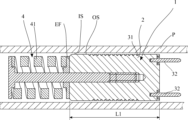
図1は、本発明の第1の実施の形態に係る電気融着プラグの正面図である。図2は、本発明の第1の実施の形態に係る電気融着プラグの断面図である。
(First embodiment)
FIG. 1 is a front view of an electric fusion plug according to a first embodiment of the present invention. FIG. 2 is a sectional view of the electrofusion plug according to the first embodiment of the present invention.
図1に示すように、電気融着プラグ1は、プラグ本体部2と発熱部3と本体圧縮部4とを有している。
As shown in FIG. 1, the
プラグ本体部2は、閉塞しようとする図示しない熱可塑性樹脂製の管Pと同じ熱可塑性樹脂で円柱形状に形成されている。プラグ本体部2の外径は、管Pの内径側に容易に挿入できるように、管Pの内径よりも細く形成されている。
The
発熱部3は、プラグ本体部2の外周部に配置されている。発熱部3は、プラグ本体部2の外周部に形成されている2条の螺旋溝21に埋め込まれている電熱線31である。電熱線31は、プラグ本体部2の軸線方向の一方の側(図1におけるプラグ本体部2の右側)から他方の側(図1におけるプラグ本体部2の左側)に向かって螺旋溝21に埋め込まれて巻回されている。更に、電熱線31は、他方の側で折り返されて一方の側に向かって螺旋溝21に埋め込まれて外周部に巻回されている。このように、電熱線31は、その両端がプラグ本体部2の軸線方向の一方の側(図1におけるプラグ本体部2の右側)に来るように設けられている。電熱線31の両端は、プラグ本体部2の一方の側に固定されている通電用のコネクタピン32に接続されている。管Pに電気融着プラグ1を融着接合する際、電熱線31は、コネクタピン32に接続された図示しない融着用電源装置によって通電されることで発熱して、プラグ本体部2と管Pとを加熱溶融させる。
The
発熱部3は、プラグ本体部と管とを加熱溶融することができればよく、図1に示す形態に限られず、他の形態の発熱部であってもよい。例えば、発熱部は、螺旋溝が形成されていない円柱形状のプラグ本体部の外周部に巻回されている、外周が熱可塑性樹脂で被覆されている電熱線(所謂、樹脂被覆電熱線)であってもよい。
The
プラグ本体部押圧手段4は、弾性部材41と、保持部材42と、中間部材43とを有し、プラグ本体部2の片側(図1におけるプラグ本体部2の左側)の端部に設けられ、プラグ本体部2を軸線方向に押圧している。
The plug body pressing means 4 includes an
プラグ本体部押圧手段4の各部の詳細を順に説明する。
弾性部材41は、例えば、コイルばねであり、圧縮される方向に貫通する空洞が形成されている、弾性を有する筒状の部材である。弾性部材41は、圧縮されることで圧縮方向と逆側に向かって反発する。弾性部材41は、コイルばねの他に、弾性を有する例えばゴムなどの材料で形成された筒状の部材であってもよい。
The details of each part of the plug body pressing means 4 will be explained in order.
The
保持部材42は、軸部421と圧縮部422とで構成されている。
軸部421は、プラグ本体部2の端部から軸線方向に延びるように設けられ、弾性部材41の空洞に通されて弾性部材41を保持している。軸部421は、プラグ本体部2の側の端部外周におねじ423が形成されている。軸部421は、プラグ本体部2に形成されている本体めねじ22におねじ423がねじ込まれることで、プラグ本体部2に少なくとも一部が固定されている。
The holding
The
圧縮部422は、軸部421における、プラグ本体部2の側と逆側の端部に設けられている、軸部421よりも外径が大きくなるよう設けられている部分である。圧縮部422は、例えば、軸部421の端部に一体で形成されている鍔である。圧縮部422は、おねじ423を本体めねじ22にねじ込むことで、弾性部材41の端部を押して弾性部材41をプラグ本体部2に向かって圧縮している。圧縮部422は、軸部と一体に形成された鍔の他に、ねじ込みなどの手段によって軸部421の端部に設けられてもよい。
The
中間部材43は、弾性部材41とプラグ本体部2の間に挟まれて設けられている、例えば平座金などのリング部材である。弾性部材41とプラグ本体部2との間に中間部43を介在させることで、圧縮に伴う弾性部材41の反発力が、プラグ本体部2の端面EFに均等に伝えられる。したがって、弾性部材41とプラグ本体部2との間に中間部材43を介在させることが好ましい。一方で、弾性部材41をプラグ本体部2に直接接触させても必要かつ十分な程度にプラグ本体部2の端面EFに均等に弾性部材41の反発力を伝えることができる場合には、中間部材43は省略することができる。
The
次いで、電気融着プラグ1を使用して管Pの内部を閉塞する際の、電気融着プラグの動きを図3及び図4を参照して説明する。図3は、管Pの内部に電気融着プラグ1が挿入された状態を示し、図4は、管Pと電気融着プラグ1が融着されている状態を示す断面図である。
Next, the movement of the
図3に示すように、電気融着プラグ1は、管Pの内部に挿入される。電気融着プラグ1は、管Pの内部の所定の位置まで、管Pの管端(図示を省略)から軸線方向に沿って挿入される。電気融着プラグ1は、例えば、挿入用の棒状の部材などの何らかの挿入手段によって管Pに挿入される。
As shown in FIG. 3, the
電気融着プラグ1は、プラグ本体部2の外径が管Pの内径よりも細く形成されており、図3に示すように、管Pに挿入されたときには、プラグ本体部2の外面OSと電気融着継手1の内面ISとの間に隙間が形成されるようになっている。よって、電気融着プラグ1は、管Pの内部に容易に挿入される。また、挿入抵抗が小さいので管端から比較的遠い位置にも容易に挿入される。また、電気融着プラグ1は、挿入しようとする管Pが曲っていても、その曲りの程度が、挿入の際にプラグ本体部2の外面OSと電気融着継手1の内面ISとの間の隙間がなくならない程度のものであれば、管Pの内部に容易に挿入される。
The
電気融着プラグ1は、管Pの内部の所定の位置まで挿入されたのち、コネクタピン32に接続されている融着用電源装置(図示を省略)によって電熱線31に通電することによって、図4に示すように管Pの内部と融着接合される。
After the
電熱線31に通電されると、プラグ本体部2は、電熱線31が発熱することで加熱されて溶融する。加熱されて軟化したプラグ本体部2は、端面EFがプラグ本体押圧手段4によって押圧されているので、弾性部材41の反発力を受けて変形する。プラグ本体部2の軸心方向に沿った長さはL1からL2に短くなる。ここで、L1は変形前のプラグ本体部2の軸心方向の長さであり、L2は変形後のプラグ本体部2の軸心方向の長さである。プラグ本体部2の体積は大きく変わらないので、プラグ本体部2は、図4に示すように長さが短くなるに伴って外径が拡大する。プラグ本体部2は、管Pの内面ISとの隙間を埋めるように外径が拡大して、外面OSが管Pの内面ISに密着する。電気融着プラグ1は、プラグ本体部2の外面OSと管Pの内面ISとが密着することで、電熱線31の熱が両方にしっかりと伝わるので、管Pと確実に融着接合される。
When the
(第2の実施の形態)
図5は、本発明の第2の実施の形態に係る電気融着プラグの断面図である。
(Second embodiment)
FIG. 5 is a sectional view of an electrofusion plug according to a second embodiment of the present invention.
第2の実施の形態に係る電気融着プラグにおいて、第1の実施の形態に係る電気融着プラグと共通する部分については、同一の参照符号を付して説明を省略する。 In the electric fusion plug according to the second embodiment, parts common to the electric fusion plug according to the first embodiment are given the same reference numerals, and the description thereof will be omitted.
図5に示すように、電気融着プラグ1aは、プラグ本体部2aと発熱部3とプラグ本体押圧手段4aとを有している。
As shown in FIG. 5, the electric fusion plug 1a has a
プラグ本体部押圧手段4aは、保持部材42aと弾性部材41と中間部材43とを有し、プラグ本体部2aの片側(図5におけるプラグ本体部2aの左側)の端部に設けられ、プラグ本体部2aを軸線方向に押圧している。
The plug body pressing means 4a includes a holding
保持部材42aは、軸部421aと圧縮部422aとで構成されている。
軸部421aは、弾性部材41の空洞に通されることが可能な外径の円柱であって、インサート成形によりプラグ本体部2aに設けられている。軸部421aのプラグ本体部2a側の端部には大径部423aが形成されている。大径部423aは、インサート成形によりプラグ本体部2aの内部に埋め込まれている。軸部421aは、大径部がプラグ本体部2aに引っかかっていることで、プラグ本体部2aに対して軸線方向に固定されている。
The holding
The
また、軸部421aは、プラグ本体部2aの端部から軸線方向に延びるように設けられ、端部外周におねじ424aが形成されている。軸部421aは、空洞に通されて弾性部材41を保持し、弾性部材41は、おねじ424aにナットなどの圧縮部422aをねじ込むことによって圧縮されている。
Further, the
(その他の実施の形態)
図1又は図5の電気融着プラグでは、弾性部材41はプラグ本体部に向かって圧縮されて装着されることで、圧縮と逆方向の力によってプラグ本体部を軸線方向に押圧しているが、本発明において弾性部材の形態はこれに限られない。弾性部材は、引き伸ばした状態でプラグ本体部に装着され、縮もうとする力を使ってプラグ本体部を軸線方向に押圧するものであってもよい。また、弾性部材は、プラグ本体部を軸線方向に押圧可能に設けることができるものであれば、筒状に限られず中実であってもよい。
(Other embodiments)
In the electrofusion plug shown in FIG. 1 or 5, the
1、1a:電気融着プラグ
2、2a:プラグ本体部
21:螺旋溝
22:本体めねじ
OS:外面
EF:端面
3:発熱部
31:電熱線
32:コネクタピン
4、4a:プラグ本体部押圧手段
41:弾性部材
42、42a:保持部材
421、421a:軸部
422、422a:圧縮部
423:おねじ
423a:大径部
424a:おねじ
43:中間部材
P:管
IS:内面
1, 1a:
Claims (4)
前記プラグ本体部の外周部に配置されている発熱部と、
前記プラグ本体部を軸線方向に押圧しているプラグ本体部押圧手段と、を有し、
前記プラグ本体部押圧手段は、
圧縮されることで圧縮方向と逆側の方向に向かって反発する弾性部材と、
前記プラグ本体部に少なくとも一部が固定されており、前記弾性部材を圧縮した状態で保持している保持部材と、を有する、
電気融着プラグ。 A cylindrical plug body made of thermoplastic resin,
a heat generating part disposed on the outer periphery of the plug main body;
a plug body pressing means for pressing the plug body in the axial direction ;
The plug body pressing means includes:
an elastic member that rebounds in a direction opposite to the compression direction when compressed;
a holding member that is at least partially fixed to the plug body and holds the elastic member in a compressed state;
Electric fusion plug.
前記保持部材は、
前記プラグ本体部に少なくとも一部が固定され、前記プラグ本体部の端部から軸線方向に延びるように設けられ、前記空洞に通されて前記弾性部材を保持している軸部と、
前記軸部における、前記プラグ本体部の側と逆側の端部に設けられ、前記弾性部材を前記プラグ本体部に向かって圧縮している圧縮部と、を有する、
請求項1に記載の電気融着プラグ。 The elastic member has a cylindrical shape with a cavity penetrating in the direction of compression,
The holding member is
a shaft portion that is at least partially fixed to the plug body portion, is provided to extend in the axial direction from an end of the plug body portion, and is passed through the cavity and holds the elastic member;
a compression part that is provided at an end of the shaft part on a side opposite to the plug main body part and compresses the elastic member toward the plug main body part;
An electrofusion plug according to claim 1 .
請求項2に記載の電気融着プラグ。 The shaft portion is provided to be screwed together with the plug main body portion,
An electrofusion plug according to claim 2 .
請求項2に記載の電気融着プラグ。 The shaft portion is provided by insert molding in the plug body portion,
An electrofusion plug according to claim 2 .
Priority Applications (1)
| Application Number | Priority Date | Filing Date | Title |
|---|---|---|---|
| JP2019114211A JP7361507B2 (en) | 2019-06-20 | 2019-06-20 | electric fusion plug |
Applications Claiming Priority (1)
| Application Number | Priority Date | Filing Date | Title |
|---|---|---|---|
| JP2019114211A JP7361507B2 (en) | 2019-06-20 | 2019-06-20 | electric fusion plug |
Publications (2)
| Publication Number | Publication Date |
|---|---|
| JP2021001618A JP2021001618A (en) | 2021-01-07 |
| JP7361507B2 true JP7361507B2 (en) | 2023-10-16 |
Family
ID=73993947
Family Applications (1)
| Application Number | Title | Priority Date | Filing Date |
|---|---|---|---|
| JP2019114211A Active JP7361507B2 (en) | 2019-06-20 | 2019-06-20 | electric fusion plug |
Country Status (1)
| Country | Link |
|---|---|
| JP (1) | JP7361507B2 (en) |
Citations (5)
| Publication number | Priority date | Publication date | Assignee | Title |
|---|---|---|---|---|
| JP2001082665A (en) | 1999-09-16 | 2001-03-30 | Mitsubishi Plastics Ind Ltd | Electric fusion type branch pipe joint |
| JP2001355784A (en) | 2000-06-15 | 2001-12-26 | Hitachi Metals Ltd | Pipe fixing jig and pipe fixing method for electro-fusion joint |
| JP2009097657A (en) | 2007-10-18 | 2009-05-07 | Hitachi Metals Ltd | Electrofusion plug and method for treating pipe end |
| CN102537571A (en) | 2012-01-06 | 2012-07-04 | 阴法军 | Pipe joint used for connecting polyethylene plastic-steel winding pipes |
| JP2019173915A (en) | 2018-03-29 | 2019-10-10 | 日立金属株式会社 | Joint member, pipe connector and valve gear |
Family Cites Families (8)
| Publication number | Priority date | Publication date | Assignee | Title |
|---|---|---|---|---|
| JPS62279922A (en) * | 1986-05-29 | 1987-12-04 | Sekisui Chem Co Ltd | Method of lining flanged pipe and lining equipment to be used for that |
| JPH05278110A (en) * | 1992-04-01 | 1993-10-26 | Sekisui Chem Co Ltd | Joining method for synthetic resin pipe |
| JP3265405B2 (en) * | 1992-10-09 | 2002-03-11 | 東亜高級継手バルブ製造株式会社 | Manufacturing method of electrofusion joint |
| JPH06207698A (en) * | 1992-11-17 | 1994-07-26 | Sekisui Chem Co Ltd | Pipe line blocking cap |
| JP3343398B2 (en) * | 1993-06-22 | 2002-11-11 | 積水化学工業株式会社 | Manufacturing method of pipe closing cap |
| JPH07243577A (en) * | 1994-03-08 | 1995-09-19 | Osaka Gas Co Ltd | Plugging device for pipe |
| JPH08187800A (en) * | 1995-01-05 | 1996-07-23 | Sekisui Chem Co Ltd | Production of cap for closing pipeline |
| JPH08336892A (en) * | 1995-06-12 | 1996-12-24 | Sekisui Chem Co Ltd | Die for manufacturing tube joint, manufacture of the joint by using the die and the joint |
-
2019
- 2019-06-20 JP JP2019114211A patent/JP7361507B2/en active Active
Patent Citations (5)
| Publication number | Priority date | Publication date | Assignee | Title |
|---|---|---|---|---|
| JP2001082665A (en) | 1999-09-16 | 2001-03-30 | Mitsubishi Plastics Ind Ltd | Electric fusion type branch pipe joint |
| JP2001355784A (en) | 2000-06-15 | 2001-12-26 | Hitachi Metals Ltd | Pipe fixing jig and pipe fixing method for electro-fusion joint |
| JP2009097657A (en) | 2007-10-18 | 2009-05-07 | Hitachi Metals Ltd | Electrofusion plug and method for treating pipe end |
| CN102537571A (en) | 2012-01-06 | 2012-07-04 | 阴法军 | Pipe joint used for connecting polyethylene plastic-steel winding pipes |
| JP2019173915A (en) | 2018-03-29 | 2019-10-10 | 日立金属株式会社 | Joint member, pipe connector and valve gear |
Also Published As
| Publication number | Publication date |
|---|---|
| JP2021001618A (en) | 2021-01-07 |
Similar Documents
| Publication | Publication Date | Title |
|---|---|---|
| US4703150A (en) | Weldable connecting member for connecting or joining thermoplastic pipe elements | |
| JP7361507B2 (en) | electric fusion plug | |
| KR102429702B1 (en) | Pipeline comprising a connector as well as a method for operating said pipeline | |
| JP2019501348A (en) | Connector with mounting aid and method of forming the connector | |
| KR100880384B1 (en) | Coupling structure of plastic pipe for preventing leakage of fluid | |
| US6198081B1 (en) | Welding sleeve of thermoplastic material with indicator | |
| JP2562781B2 (en) | Resin tube connection structure | |
| JP6987880B2 (en) | Heated conduit with plug and how this conduit works | |
| KR102181682B1 (en) | Angle pipe adaptor for faucet | |
| JPWO2021149832A5 (en) | ||
| JPH04145294A (en) | Transfer coupling between resin tube and metal tube | |
| JP2019173915A (en) | Joint member, pipe connector and valve gear | |
| JPH045876B2 (en) | ||
| JP6904698B2 (en) | Branch saddle fitting | |
| JP2003343788A (en) | Pipe joint | |
| KR101353507B1 (en) | Connecting pipe for electirc fusion | |
| JP2020015226A (en) | Method for manufacturing resin tube member | |
| KR200344542Y1 (en) | pipe coupler | |
| JP5173571B2 (en) | Electrofusion fitting | |
| JP2005214251A (en) | Connecting method for resin pipe | |
| JPH071074B2 (en) | Pipe fitting | |
| JP5839565B2 (en) | Electrical fusion joint fittings and electric fusion joints with joints | |
| JP2676494B2 (en) | Electrofusion joint joint fitting retaining method | |
| JPH08145268A (en) | Length adjusting coupling for electric fusion | |
| JP3003003B2 (en) | Synthetic resin pipe fittings |
Legal Events
| Date | Code | Title | Description |
|---|---|---|---|
| A521 | Request for written amendment filed |
Free format text: JAPANESE INTERMEDIATE CODE: A523 Effective date: 20190624 |
|
| A711 | Notification of change in applicant |
Free format text: JAPANESE INTERMEDIATE CODE: A712 Effective date: 20220509 |
|
| A621 | Written request for application examination |
Free format text: JAPANESE INTERMEDIATE CODE: A621 Effective date: 20220513 |
|
| A521 | Request for written amendment filed |
Free format text: JAPANESE INTERMEDIATE CODE: A523 Effective date: 20220527 |
|
| RD04 | Notification of resignation of power of attorney |
Free format text: JAPANESE INTERMEDIATE CODE: A7424 Effective date: 20220624 |
|
| A977 | Report on retrieval |
Free format text: JAPANESE INTERMEDIATE CODE: A971007 Effective date: 20230324 |
|
| A131 | Notification of reasons for refusal |
Free format text: JAPANESE INTERMEDIATE CODE: A131 Effective date: 20230411 |
|
| A601 | Written request for extension of time |
Free format text: JAPANESE INTERMEDIATE CODE: A601 Effective date: 20230609 |
|
| A521 | Request for written amendment filed |
Free format text: JAPANESE INTERMEDIATE CODE: A523 Effective date: 20230804 |
|
| TRDD | Decision of grant or rejection written | ||
| A01 | Written decision to grant a patent or to grant a registration (utility model) |
Free format text: JAPANESE INTERMEDIATE CODE: A01 Effective date: 20230905 |
|
| A61 | First payment of annual fees (during grant procedure) |
Free format text: JAPANESE INTERMEDIATE CODE: A61 Effective date: 20231003 |
|
| R150 | Certificate of patent or registration of utility model |
Ref document number: 7361507 Country of ref document: JP Free format text: JAPANESE INTERMEDIATE CODE: R150 |