JP7360831B2 - Fixtures with top plate - Google Patents
Fixtures with top plate Download PDFInfo
- Publication number
- JP7360831B2 JP7360831B2 JP2019128702A JP2019128702A JP7360831B2 JP 7360831 B2 JP7360831 B2 JP 7360831B2 JP 2019128702 A JP2019128702 A JP 2019128702A JP 2019128702 A JP2019128702 A JP 2019128702A JP 7360831 B2 JP7360831 B2 JP 7360831B2
- Authority
- JP
- Japan
- Prior art keywords
- top plate
- auxiliary
- fixture
- support
- support body
- Prior art date
- Legal status (The legal status is an assumption and is not a legal conclusion. Google has not performed a legal analysis and makes no representation as to the accuracy of the status listed.)
- Active
Links
Images


Landscapes
- Tables And Desks Characterized By Structural Shape (AREA)
Description
本発明は、天板付き什器に関する。 The present invention relates to a fixture with a top plate.
従来、オフィスや病院、公共施設、研究施設等の室内空間においては、執務者に作業エリアを提供するために天板付き什器を使用するのが一般的となっている。このような天板付き什器の構造としては、例えば特許文献1~3に示されるように、左右に離間して床面上に立設された支持脚体と、左右の支持脚体に支持される左右に長寸の平板上の天板とを有するテーブル什器が多く採用されている。これらのテーブル什器を採用することにより、簡易的な構造でありながら、テーブル什器を強固かつ安定的に構成することができる。
BACKGROUND ART Conventionally, in indoor spaces such as offices, hospitals, public facilities, and research facilities, it has been common to use fixtures with tops to provide work areas for workers. The structure of such a fixture with a top plate is, for example, as shown in
しかしながら、天板付き什器を用いた執務では天板上に電子機器を用いるケースがあり、天板付き什器の天板上には電子機器に接続される電源ケーブルや情報ケーブルを収容可能とされることが求められている。ところが、配線収容部を天板上に配設してしまうと、天板上を連続する一つの作業面として使用することができなくなり、作業面が狭くなってしまうという問題があった。
また、配線収容部が設けられた天板と、配線収容部が設けられていない天板との二種類を品揃える必要があり、在庫管理の上で煩雑になることから、その点で改善の余地があった。
However, in offices that use fixtures with a top plate, there are cases where electronic devices are used on the top plate, and the top plate of fixtures with a top plate can accommodate power cables and information cables that are connected to electronic devices. That is what is required. However, if the wiring housing section is disposed on the top plate, there is a problem in that the top plate cannot be used as one continuous work surface, and the work surface becomes narrow.
In addition, it is necessary to have two types of products: one with a wiring accommodating section and one without a wiring accommodating section, which complicates inventory management. There was room.
本発明は、上述する問題点に鑑みてなされたもので、使用者の要望に応じて拡張機能を有する補助天板を設けることによって、天板の作業面を広く確保することができ、かつ異なる拡張機能を有する複数の天板を品揃えする必要がなく天板の共通化を図ることができる天板付き什器を提供することを目的とする。 The present invention has been made in view of the above-mentioned problems, and by providing an auxiliary top plate with an expansion function according to the user's request, it is possible to secure a wide working surface of the top plate, and To provide a fixture with a top plate that can use a common top plate without the need to stock a plurality of top plates having extended functions.
上記目的を達成するため、本発明に係る天板付き什器は、平板状の天板と、床面上に互いに左右に離間して配設されて前記天板を支持するとともに、それぞれ前記天板の左右方向の外側端部よりも外方に配された上面を有する一対の支持体と、前記支持体の前記上面を閉塞するように前記天板の左右方向の外側端部よりも外方に配設され、拡張機能を有する補助天板と、を備え、前記補助天板の上面は、前記天板の上面と面一となるように配置され、前記支持体は、前後方向に互いに離間して上下方向に延びる一対の脚部と、前記一対の脚部の上端同士を連結する連結部と、を有し、前記補助天板の前後端縁部は、前記支持体の前記連結部の前後端縁部よりも前後方向に張り出して設けられ、前記補助天板の下方には、前記連結部の前後方向両側に什器に設けるオプション部材を取り付け可能な空間が形成されていることを特徴としている。 In order to achieve the above object, a fixture with a top plate according to the present invention includes a flat top plate, and supports the top plate by being disposed on the floor spaced apart from each other in the left and right directions, and supports the top plate, respectively. a pair of supports having upper surfaces disposed outwardly from the outer ends in the left and right direction of the top plate; an auxiliary top plate arranged and having an expansion function, the top surface of the auxiliary top plate is arranged to be flush with the top surface of the top plate , and the supports are spaced apart from each other in the front-rear direction. a pair of legs extending in the vertical direction; and a connecting part connecting the upper ends of the pair of legs; The auxiliary top plate is provided so as to protrude from the end edge in the front-rear direction, and a space is formed below the auxiliary top plate in which optional members to be provided on the fixture can be attached to both sides of the connection part in the front-rear direction. .
本発明では、補助天板が天板の左右方向の外側端部よりも外方に設けられ、補助天板に拡張機能をもたせることができる。例えば、補助天板の拡張機能として配線収容部を備えたものを使用することで、天板上に配線収容部を配置する必要がなくなり、天板の作業面を広く確保することができる。また、補助天板は天板と別体で設けられるので、拡張機能の異なる補助天板を品揃えておくことで、使用者の要望に応じた拡張機能を有する補助天板を使用すればよい。つまり、本発明による天板付き什器では、異なる拡張機能を有する複数の天板を品揃えする必要がなくなるため、天板の共通化を図ることができ、什器としての使い勝手を良好なものとすることができる。
また、本発明では、支持体の上面が補助天板で覆われているので、補助天板の上面に物品を載置することもできる。
また、この場合には、支持体の連結部よりも前後方向に突出する天板の下方に、什器に設けるオプション部材を取り付け可能な空間が形成されているので、支持体を圧迫感が無い体裁に収めることができる。また、前記空間を形成することにより、天板の下方の空間をより広く確保することができ、什器としての使い勝手を良好なものとすることができる。
In the present invention, the auxiliary top plate is provided outward from the outer end of the top plate in the left-right direction, so that the auxiliary top plate can have an expansion function. For example, by using an auxiliary top board with a wiring accommodating part as an extended function, it becomes unnecessary to arrange the wiring accommodating part on the top board, and a wide work surface of the top board can be secured. In addition, since the auxiliary top board is provided separately from the top board, by stocking up on auxiliary top boards with different extension functions, it is possible to use the auxiliary top board with the extension function that meets the needs of the user. . In other words, the fixture with a top plate according to the present invention eliminates the need to assemble a plurality of top plates with different extended functions, making it possible to use a common top plate and making the fixture easy to use. be able to.
Furthermore, in the present invention, since the upper surface of the support is covered with the auxiliary top plate, articles can also be placed on the upper surface of the auxiliary top plate.
In addition, in this case, a space is formed below the top plate that protrudes in the front-rear direction beyond the connection part of the support body, so that an optional component for the fixture can be attached, so that the support body can be placed in an appearance that does not feel oppressive. can be accommodated in Moreover, by forming the space, a wider space can be secured under the top plate, and the usability as a fixture can be improved.
また、本発明に係る天板付き什器は、前記支持体には、左右方向で前記天板側に向けて突出し、前記天板の外側端部を下方から支持するアーム部が設けられていることを特徴としてもよい。 Further, in the fixture with a top plate according to the present invention, the support body is provided with an arm portion that protrudes toward the top plate side in the left-right direction and supports an outer end of the top plate from below. may be a feature.
この場合には、左右方向で天板の外側端部よりも外方に配設される支持体にアーム部を介して天板を支持することができる。しかも天板の外側端部をアーム部によって下方から支持することができるので、天板を強固に固定することができる。このとき、支持体の上面には天板を固定する部材が設けられることがなく、支持体の上面全体を補助天板によって覆うことができるので、什器としての使い勝手を良好なものとすることができる。 In this case, the top plate can be supported via the arm portion on a support body disposed outward from the outer end of the top plate in the left-right direction. Moreover, since the outer end of the top plate can be supported from below by the arm portion, the top plate can be firmly fixed. At this time, no member is provided on the top surface of the support to fix the top plate, and the entire top surface of the support can be covered by the auxiliary top plate, making it easy to use as a fixture. can.
また、本発明に係る天板付き什器は、平板状の天板と、床面上に互いに左右に離間して配設されて前記天板を支持するとともに、それぞれ前記天板の左右方向の外側端部よりも外方に配された上面を有する一対の支持体と、前記支持体の前記上面を閉塞するように前記天板の左右方向の外側端部よりも外方に配設され、拡張機能を有する補助天板と、を備え、前記補助天板の上面は、前記天板の上面と面一となるように配置され、前記補助天板と前記支持体の上面との間に物品を収容可能な物品収容空間が形成されていることを特徴としている。 Further, the fixture with a top plate according to the present invention includes a flat top plate, and supports the top plate by being disposed on the floor spaced apart from each other in the left and right directions, and also supports the top plate on the outside of the top plate in the left and right direction. a pair of supports having upper surfaces disposed outward from the ends; and a pair of supports disposed outward from the outer ends in the left-right direction of the top plate so as to close the upper surfaces of the supports; an auxiliary top plate having a function, the top surface of the auxiliary top plate is arranged flush with the top surface of the top plate, and an article is placed between the auxiliary top plate and the top surface of the support. It is characterized by having a space for accommodating articles.
本発明では、執務者の使用用途に応じて、補助天板と支持体の上面との間に形成される物品収容空間を、例えば配線を挿通するための空間として利用することができることから、什器としての使い勝手を良好なものとすることができる。 In the present invention, the article storage space formed between the auxiliary top plate and the upper surface of the support can be used, for example, as a space for inserting wiring, depending on the purpose of use of the office worker. It is possible to improve the usability of the device.
また、本発明に係る天板付き什器は、前記補助天板には、電源や通信用のコンセントが備えられ、電源ケーブルや通信ケーブルを接続する拡張機能が設けられていることを特徴としてもよい。 Furthermore, the fixture with a top plate according to the present invention may be characterized in that the auxiliary top plate is provided with an outlet for power and communication, and is provided with an extended function for connecting a power cable and a communication cable. .
この場合には、補助天板に電源や通信用のコンセントの機能をもたせることができるので、天板上で電子機器等を使用する場合における天板付き什器としての使い勝手をより良好なものとすることができる。 In this case, the auxiliary top plate can function as a power source or a communication outlet, making it easier to use as a fixture with a top plate when using electronic devices, etc. on the top plate. be able to.
本発明の天板付き什器によれば、使用者の要望に応じて拡張機能を有する補助天板を設けることによって、天板の作業面を広く確保することができ、かつ異なる拡張機能を有する複数の天板を品揃えする必要がなく天板の共通化を図ることができる。 According to the fixture with a top plate of the present invention, by providing an auxiliary top plate with an expansion function according to the user's request, a wide work surface of the top plate can be secured, and multiple pieces of furniture with different expansion functions can be used. There is no need to stock up on different types of top plates, and it is possible to standardize the top plates.
以下、本発明の実施形態による天板付き什器について、図面に基づいて説明する。 Hereinafter, a fixture with a top plate according to an embodiment of the present invention will be described based on the drawings.
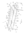
図1~図6に示す本実施形態による天板付き什器は、オフィスや教育施設や家庭などの執務空間に設けられるテーブル什器1に適用したものである。
テーブル什器1は、床面F上に互いに左右に離間して配設された一対の支持体2と、支持体2に支持された平板状の天板3と、支持体2の上面を閉塞し、天板3の左右の外側端部よりも外方に配設され、拡張機能(図11(a)~(c)参照)を有する補助天板4と、を有している。支持体2は、一対の支持体2、2同士を連結する連結フレーム21(図7参照)とともに支持構造体20として構成されている。
The fixture with a top plate according to the present embodiment shown in FIGS. 1 to 6 is applied to a
The
ここで、本実施形態では、テーブル什器1に向かって着席した状態での左右方向を符号Dhとし、上方から見た平面視で左右方向Dhに直交する方向を前後方向Dfという。また、テーブル什器1の前後方向Dfにおいて、天板3に向かう一方(図1の紙面手前)の椅子側(不図示)を前方、前側といい、前後方向Dfで前方の反対側を後方、後側という。
Here, in this embodiment, the left-right direction in a state where the person is seated facing the
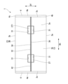
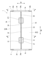
テーブル什器1は、上方から見て左右方向Dhに長い長方形状をなしている。
天板3(3A、3B)は、前後方向Dfに二分割され、支持構造体20の連結フレーム21の上面に固定されている。分割された天板3A、3Bの中央端3d、3d同士は、互いに一定の隙間(溝部32)をあけて配置されている。各天板3A、3Bの中央端3dには、後方に開口する一対の開口凹部31が左右方向Dhに間隔をあけて形成されている。分割された一対の天板3A,3Bを支持構造体20の所定位置に固定した状態で、一対の天板3A,3Bの開口凹部31、31同士によって略四角形の開口が形成される。この開口には、後述する支持構造体20のコンセント部27が配置される。
The
The top plate 3 (3A, 3B) is divided into two parts in the front-rear direction Df, and is fixed to the upper surface of the
支持構造体20は、図7に示すように、一対の支持体2、2と、一対の支持体2、2同士を連結する連結フレーム21と、支持体2の上部から左右方向Dhの内側に向かって突出し、天板3の外側端部3cを下方から支持する天板支持部22(アーム部)と、を備えている。
As shown in FIG. 7, the
支持体2は、天板3の左右両側において互いに前後に離間して一対で設けられている。支持体2は、前後に互いに離間して上下方向に向かって立設された一対の支持脚23(23A、23B)(脚部)と、一対の支持脚23A、23Bの上端同士を連結する連結部24と、を有している。
The
支持脚23(23A、23B)は、図8~図10に示すように、前後に離間して一対で設けられている。一対の支持脚23A、23Bのうち前側支持脚23Aが連結部24の前端縁部24bから下方に向かうに従って漸次前方に傾斜し、後側支持脚23Bが連結部24の後端縁部24cから下方に向かうに従って漸次後方に傾斜している。支持脚23は、下方に向けて漸次細くなる帯板を断面く字状に折り曲げた形状である。支持脚23は、上部が前後方向Dfの内側に凸となる上部折曲げ凸部23aを形成し、上部折曲げ凸部23aよりも下方の部分が前後方向Dfの外側に凸となる下部折曲げ凸部23bを形成している。つまり、支持脚23は、上部折曲げ凸部23aと下部折曲げ凸部23bとは凸部分が反転した形状になっている。
As shown in FIGS. 8 to 10, the support legs 23 (23A, 23B) are provided as a pair spaced apart from each other in the front and rear. Of the pair of
連結部24は、前側支持脚23Aと後側支持脚23Bのそれぞれの上部同士の間を架設するフレーム部材である。連結部24は、長さ方向(前後方向Df)の全体にわたって下側に凸となるように帯板を断面く字状に折り曲げた形状をなし、長さ方向の両端が支持脚23A、23Bの上部折曲げ凸部23aに接続されている。連結部24の上面は、図4に示すように、天板3の外側端部3cよりも外方に配設され、前後方向Dfに延びるとともに下方に向かって凹む凹溝からなる物品載置部24aが形成されている。連結部24には、上方を閉塞する上記補助天板4が設けられている(図3参照)。
The connecting
そのため、補助天板4と連結部24の上面の物品載置部24aとの間には第1空間S1(物品収容空間)(図10参照)が形成されている。第1空間S1は、例えば配線収容空間として使用することが可能であり、天板3の中央のコンセント部から延長させた配線等を収容することができる。
なお、支持体2は、鋼材から形成され、連結部24と一対の支持脚23A、23Bとは溶接により接合されている。
Therefore, a first space S1 (article storage space) (see FIG. 10) is formed between the auxiliary
Note that the
連結フレーム21は、図7に示すように、左右方向Dhに離間する支持体2、2の連結部24、24同士の間に前後方向Dfに延びる中間フレーム25が設けられ、この中間フレーム25と左右の連結部24、24とを架設する複数の左右フレーム26が設けられている。
中間フレーム25及び左右フレーム26は、それぞれ上面25a、26aが面一となる平らな面を形成している。
As shown in FIG. 7, the connecting
The
連結フレーム21における前後方向Dfの中央部には、天板3上で使用するコンピュータ等の電子機器の配線ケーブルを電気的に接続するコンセント部27が設けられている。コンセント部27には、上方を開閉可能な蓋部271が設けられている。
At the center of the connecting
天板支持部22は、支持体2の連結部24の内側面から左右方向Dhの内側に向けて突出している。天板支持部22は、互いに前後方向Dfに離間した位置で、前記左右フレーム26の端部を接続可能な位置に複数(ここでは4箇所)配置されている。天板支持部22は、図6、図8~図10に示すように、左右フレーム26を上方から係合可能な凹部221と、凹部221の両上端部から前後方向に張り出した平板状の受け板222と、を有している。
The
天板支持部22は、凹部221に上方から係合される左右フレーム26の上面26aと受け板222の上面222aとは面一になっている。
受け板222にはボルト孔222bが形成されている。天板3は、受け板222上に載置され、受け板222のボルト孔222bに下方から挿通させたボルト又はねじ(図示省略)によって締め付けられて支持構造体20(図7参照)に固定されている。
In the top
A
図5及び図6に示すように、天板3の前端縁部3a及び後端縁部3bは、それぞれ支持体2の連結部24の前端縁部24b及び後端縁部24cよりも前後方向Dfに張り出して設けられている。
そして、天板3の下方には、連結部24よりも前後方向Df両側に什器に設けるオプション部材(図示省略)を取り付け可能な第2空間S2が形成されている。なお、オプション部材としては、物品を引っ掛けるためのフック部材等が挙げられる。
As shown in FIGS. 5 and 6, the
A second space S2 is formed below the
補助天板4は、図1~図3に示すように、テーブル什器1として支持体2に設けられた状態で前後方向Dfに延びる帯状板であり、天板3と同等の板厚で形成され、支持体2の連結部24上に着脱可能に装着されている。左右一対の補助天板4、4は、前後方向Dfの中央部同士が左右方向Dhに延びる連結バー42によって連結されている。連結バー42は、分割された一対の天板3A、3B同士の間の溝部32に係合されている。連結バー42を溝部32に係合させることで、左右一対の補助天板4、4が支持体2の連結部24上に配置される。
As shown in FIGS. 1 to 3, the auxiliary
このように構成される補助天板4を支持体2に取り付ける方法としては、天板3の側端部下面(第2空間S2)に側方に向かって突出する平板上のブラケット(図示省略)を取り付ける。すなわち、天板3の側端部下面側の第2空間S2を利用してブラケットを天板3に取り付ける。そして、このブラケット上に補助天板を載置し、下方からビス止めすることによって補助天板4を固定することができる。このように、補助天板4、もしくは補助天板取り付け用のブラケットは、上述したオプション部材として機能する部材でもある。
A method for attaching the auxiliary
補助天板4は、後述する異なる拡張機能を有するもの(図11(a)~(c)参照)を取り替えることができる。
補助天板4の上面4aは、天板3の上面3eと面一となるように配置されている。補助天板4の前端縁部4b及び後端縁部4cは、それぞれ天板3の前端縁部3a及び後端縁部3bと前後方向Dfに同一位置となるように配設されている。
The auxiliary
The
補助天板4として、例えば図11(a)に示すように、電源や通信用のコンセント41が備えられ、電源ケーブルや通信ケーブルを接続する拡張機能が設けられたものを使用できる。
また、図11(b)に示すように、補助天板4として、上面4aに凹まされて形成されたペントレー40が備えられ、筆記用具を収容する拡張機能が設けられたものを使用してもよい。
さらに、図11(c)に示すように、補助天板4として、上面4aから上方に立設された照明装置43が備えられ、天板3を照らす照明機能が設けられたものを採用してもよい。
あるいは、上記コンセント41、ペントレー40、及び照明装置43を適宜組み合わせた拡張機能を有するものであってもよいし、他の形態の拡張機能のものを補助天板4に備えることも可能である。
As the auxiliary
Further, as shown in FIG. 11(b), the auxiliary
Furthermore, as shown in FIG. 11(c), the auxiliary
Alternatively, the auxiliary
次に、上述したテーブル什器1の作用について、図面に基づいて詳細に説明する。
本実施形態によるテーブル什器1では、図1乃至図3に示すように、補助天板4が天板3の左右方向Dhの外側端部3cよりも外方に設けられ、補助天板4に図11(a)~(c)に示す拡張機能をもたせることができる。例えば、補助天板4の拡張機能Pとして配線収容部を備えたものを使用することで、天板3上に配線収容部を配置する必要がなくなり、天板3の作業面を広く確保することができる。
Next, the operation of the
In the
また、補助天板4は天板3と別体で設けられるので、拡張機能の異なる補助天板4を品揃えておくことで、使用者の要望に応じた拡張機能を有する補助天板4を使用すればよい。つまり、本実施形態による天板付き什器1では、異なる拡張機能を有する複数の天板を品揃えする必要がなくなるため、天板3の共通化を図ることができ、什器としての使い勝手を良好なものとすることができる。
また、本実施形態では、支持体2の連結部24の上面の物品載置部24aが補助天板4で覆われているので、補助天板4の上面4aに物品を載置することもできる。
In addition, since the auxiliary
Furthermore, in this embodiment, since the
また、本実施形態では、拡張機能を有する補助天板4を支持体2の連結部24の上面(物品載置部24a)に対して着脱することができる。そのため、使用者の要望に応じた拡張機能を有する補助天板4を装着することが可能であり、また拡張機能の異なる補助天板4に変更することも容易に行うことができるから、使用者の要望に柔軟に対応可能であり、什器としての使い勝手をより良好なものとすることができる。
Further, in this embodiment, the auxiliary
さらに、本実施形態では、補助天板4を支持体2の連結部24の上面に装着した状態において、補助天板4と天板3のそれぞれの前端縁部3aと後端縁部3bの位置が前後方向Dfに揃っていて、前後方向Dfの段差が形成されることがないので、天板付き什器1としての体裁をより良好なものとすることができる。
Furthermore, in this embodiment, in a state where the auxiliary
さらにまた、本実施形態では、支持体2の連結部24よりも前後方向Dfに突出する天板3の下方に、什器に設けるオプション部材を取り付け可能な第2空間S2が形成されているので、支持体2を圧迫感が無い体裁に収めることができる。
また、本実施形態では、第2空間S2を形成することにより、天板3の下方の空間をより広く確保することができ、什器としての使い勝手を良好なものとすることができる。
Furthermore, in this embodiment, a second space S2 is formed below the
Further, in this embodiment, by forming the second space S2, a wider space can be secured under the
さらに、本実施形態では、左右方向Dhで天板3の外側端部3cよりも外方に配設される支持体2に天板支持部22を介して天板3を支持することができる。しかも天板3の外側端部3cを天板支持部22によって下方から支持することができるので、天板3を強固に固定することができる。このとき、支持体2の連結部24の上面には天板3を固定する部材が設けられることがなく、支持体2の連結部24全体を補助天板4によって覆うことができるので、什器としての使い勝手を良好なものとすることができる。
Furthermore, in this embodiment, the
さらにまた、本実施形態では、執務者の使用用途に応じて、補助天板4と連結部24の上面の凹溝からなる物品載置部24aとの間に形成される第1空間S1を、例えば配線を挿通するための空間として利用することができることから、什器としての使い勝手を良好なものとすることができる。
Furthermore, in this embodiment, the first space S1 formed between the auxiliary
また、本実施形態では、図11(a)に示すように、補助天板4に電源や通信用のコンセントの拡張機能をもたせることができるので、天板3上で電子機器等を使用する場合における天板付き什器1としての使い勝手をより良好なものとすることができる。
In addition, in this embodiment, as shown in FIG. 11(a), the auxiliary
さらに、本実施形態では、図11(b)に示すように、補助天板4にペントレー機能をもたせることができるので、執務に使用する筆記具等をペントレー内に収容することが可能となり、天板付き什器1としての使い勝手をより良好なものとすることができる。
Furthermore, in this embodiment, as shown in FIG. 11(b), the auxiliary
さらにまた、本実施形態では、図11(c)に示すように、補助天板4に照明機能をもたせることができるので、天板3上の照度を確保することができ、天板付き什器1としての使い勝手をより良好なものとすることができる。
Furthermore, in this embodiment, as shown in FIG. 11(c), since the auxiliary
上述のように本実施形態によるテーブル什器1では、使用者の要望に応じて拡張機能を有する補助天板4を設けることによって、天板3の作業面を広く確保することができ、かつ異なる拡張機能を有する複数の天板を品揃えする必要がなく天板3の共通化を図ることができる。
As mentioned above, in the
以上、本発明による天板付き什器の実施形態について説明したが、本発明は上記の実施形態に限定されるものではなく、その趣旨を逸脱しない範囲で適宜変更可能である。 Although the embodiments of the fixture with a top plate according to the present invention have been described above, the present invention is not limited to the above-described embodiments, and can be modified as appropriate without departing from the spirit thereof.
例えば、本実施形態では、補助天板4が支持体の連結部24に対して着脱可能に設けられているが、着脱式であることに限定されることはなく、取り外し不能な状態で固定されていてもよい。
For example, in this embodiment, the auxiliary
また、本実施形態では、補助天板4の前後端縁部4b、4cが天板3の前後端縁部3a、3bと同一位置となるように配設されているが前後方向Dfにずれた状態で配置されていてもよい。
さらに、本実施形態では、天板3の前後端縁部3a、3bが支持体2の連結部24の前後端縁部24b、24cよりも前後方向Dfに張り出して設けられ、天板3の下方における連結部24よりも前後方向Dfに突出する部分に空間S2が形成されているが、このような空間S2が形成されることに限定されることはない。
In addition, in this embodiment, the front and
Furthermore, in this embodiment, the front and
さらにまた、支持体2において、上部から左右方向Dhの内側に向かって突出し、天板3の外側端部3cを下方から支持する天板支持部22(アーム部)が設けられているが、このアーム部を省略することも可能である。
Furthermore, the
また、本実施形態では、支持体2の連結部24の上面に下方に凹入された凹溝状の物品載置部24aが形成され、補助天板4との間に空間S1が形成されているが、このような物品載置部24aが形成されていない補助天板4であってもよく、上記空間S1も形成されない構成であってもかまわない。
In addition, in this embodiment, a groove-shaped
また、補助天板4の形状や形態については、本実施形態に制限されることはなく、適宜変更可能である。
例えば、図12に示す第1変形例のテーブル什器1A(天板付き什器)では、補助天板4Aがサイド幕板44を備えている。サイド幕板44の上端44aは、補助天板4Aの長手方向に延びる一方(什器外側)の側縁部4dに一体的に接続されている。これによりサイド幕板44は、補助天板4Aの側縁部4dから下方に向けて延在するように配置される。また、本第1変形例による補助天板4Aの下面は、支持体2の連結部24における下側に凸となる断面く字状に折り曲げた物品載置部24aと一致するV字形状の下凸面4eが形成されている。サイド幕板44を取り付ける際には、補助天板4Aの下凸面4eを連結部24の物品載置部24aに載置させることで左右方向Dhにずれないように係止させた状態で取り付けることができる。このように、補助天板4Aには、サイド幕板44の係止部をなすフックの機能をもたせることができる。
Further, the shape and form of the auxiliary
For example, in the
なお、補助天板4Aにフック機能をもたせて使用する場合には、第1変形例のように補助天板4Aに接続する部材としてサイド幕板44であることに限定されることはない。例えば、サイド幕板44に代えて物品を吊り下げたり掛止したりすることが可能な網状の部材や、物品を収納できる収納部材としてもよい。
Note that when the auxiliary
また、図13に示す第2変形例のテーブル什器1B(天板付き什器)に設けられる補助天板4Bは、左右方向Dhに隣り合って配置されたテーブル什器1B、1B同士を連結する機能としたものである。補助天板4Bは、天板3と同等の幅寸法(前後方向の長さ寸法)を有する板状に形成されている。補助天板4Bは、一対のテーブル什器1B、1Bのそれぞれの支持体2における連結部24の物品載置部24aに係止する係止部45A、45Aと、一対の係止部45A、45A同士を一体的に連結した連結板45Bと、を備えている。係止部45Aの下面は、支持体2の連結部24における下側に凸となる断面く字状に折り曲げた物品載置部24aと一致するV字形状の下凸面45aが形成されている。第2変形例による補助天板4Bを使用してテーブル什器1B、1B同士を連結する際には、それぞれの係止部45Aの下凸面45aをテーブル什器1Bの連結部24の物品載置部24aに載置させることで連結した状態で取り付けることができる。
Further, the auxiliary
なお、テーブル什器1における支持構造体20の支持体2、連結フレーム21の形状、寸法、数量等の構成については、本実施形態に限定されることはなく、適宜設定することができる。
また、補助天板4の寸法や形状も、本実施形態に限定されることはなく、適宜設定することができる。
Note that configurations such as the shape, dimensions, and quantity of the
Furthermore, the dimensions and shape of the auxiliary
その他、本発明の趣旨を逸脱しない範囲で、上記した実施形態における構成要素を周知の構成要素に置き換えることは適宜可能である。 In addition, it is possible to appropriately replace the components in the above-described embodiments with well-known components without departing from the spirit of the present invention.
1、1A、1B テーブル什器(天板付き什器)
2 支持体
3 天板
3a 前端縁部
3b 後端縁部
3c 外側端部
4、4A、4B 補助天板
4a 上面
21 連結フレーム
22 天板支持部(アーム部)
23 支持脚
24 連結部
40 ペントレー
41 コンセント
43 照明装置
Dh 左右方向
Df 前後方向
S1 第1空間(物品収容空間)
S2 第2空間
F 床面
1, 1A, 1B Table fixtures (fixtures with top plate)
2
23
S2 2nd space F floor surface
Claims (4)
床面上に互いに左右に離間して配設されて前記天板を支持するとともに、それぞれ前記天板の左右方向の外側端部よりも外方に配された上面を有する一対の支持体と、
前記支持体の前記上面を閉塞するように前記天板の左右方向の外側端部よりも外方に配設され、拡張機能を有する補助天板と、を備え、
前記補助天板の上面は、前記天板の上面と面一となるように配置され、
前記支持体は、前後方向に互いに離間して上下方向に延びる一対の脚部と、前記一対の脚部の上端同士を連結する連結部と、を有し、
前記補助天板の前後端縁部は、前記支持体の前記連結部の前後端縁部よりも前後方向に張り出して設けられ、
前記補助天板の下方には、前記連結部の前後方向両側に什器に設けるオプション部材を取り付け可能な空間が形成されていることを特徴とする天板付き什器。 A flat top plate,
a pair of supports that are disposed on a floor surface to be spaced apart from each other in the left and right directions to support the top plate, and each have an upper surface that is disposed outward from an outer end of the top plate in the left and right direction;
an auxiliary top plate that is disposed outwardly from an outer end in the left-right direction of the top plate so as to close the upper surface of the support body and has an expansion function;
The top surface of the auxiliary top plate is arranged to be flush with the top surface of the top plate ,
The support body has a pair of legs that are spaced apart from each other in the front-back direction and extend in the up-down direction, and a connecting part that connects the upper ends of the pair of legs,
The front and rear edges of the auxiliary top plate are provided to protrude in the front and rear direction from the front and rear edges of the connecting portion of the support,
A fixture with a top plate, characterized in that a space is formed below the auxiliary top plate, on both sides of the connecting portion in the front and rear direction, in which optional members provided on the fixture can be attached.
床面上に互いに左右に離間して配設されて前記天板を支持するとともに、それぞれ前記天板の左右方向の外側端部よりも外方に配された上面を有する一対の支持体と、
前記支持体の前記上面を閉塞するように前記天板の左右方向の外側端部よりも外方に配設され、拡張機能を有する補助天板と、を備え、
前記補助天板の上面は、前記天板の上面と面一となるように配置され、
前記補助天板と前記支持体の上面との間に物品を収容可能な物品収容空間が形成されていることを特徴とする天板付き什器。 A flat top plate,
a pair of supports that are disposed on a floor surface to be spaced apart from each other in the left and right directions to support the top plate, and each have an upper surface that is disposed outward from an outer end of the top plate in the left and right direction;
an auxiliary top plate that is disposed outwardly from an outer end in the left-right direction of the top plate so as to close the upper surface of the support body and has an expansion function;
The top surface of the auxiliary top plate is arranged to be flush with the top surface of the top plate,
A fixture with a top plate, characterized in that an article storage space capable of accommodating articles is formed between the auxiliary top plate and the upper surface of the support body.
Priority Applications (1)
| Application Number | Priority Date | Filing Date | Title |
|---|---|---|---|
| JP2019128702A JP7360831B2 (en) | 2019-07-10 | 2019-07-10 | Fixtures with top plate |
Applications Claiming Priority (1)
| Application Number | Priority Date | Filing Date | Title |
|---|---|---|---|
| JP2019128702A JP7360831B2 (en) | 2019-07-10 | 2019-07-10 | Fixtures with top plate |
Publications (2)
| Publication Number | Publication Date |
|---|---|
| JP2021013474A JP2021013474A (en) | 2021-02-12 |
| JP7360831B2 true JP7360831B2 (en) | 2023-10-13 |
Family
ID=74530978
Family Applications (1)
| Application Number | Title | Priority Date | Filing Date |
|---|---|---|---|
| JP2019128702A Active JP7360831B2 (en) | 2019-07-10 | 2019-07-10 | Fixtures with top plate |
Country Status (1)
| Country | Link |
|---|---|
| JP (1) | JP7360831B2 (en) |
Citations (6)
| Publication number | Priority date | Publication date | Assignee | Title |
|---|---|---|---|---|
| JP2005261539A (en) | 2004-03-17 | 2005-09-29 | Itoki Corp | Studying desk |
| JP2009160112A (en) | 2007-12-28 | 2009-07-23 | Okamura Corp | Furniture |
| JP2010528721A (en) | 2007-06-01 | 2010-08-26 | スティールケイス・インコーポレイテッド | Table structure |
| JP2016165363A (en) | 2015-03-09 | 2016-09-15 | 株式会社岡村製作所 | Desk apparatus |
| JP2019030605A (en) | 2017-08-10 | 2019-02-28 | 株式会社イトーキ | Panel apparatus |
| JP2019063236A (en) | 2017-09-29 | 2019-04-25 | 株式会社イトーキ | Top board support device |
Family Cites Families (1)
| Publication number | Priority date | Publication date | Assignee | Title |
|---|---|---|---|---|
| JP3690454B2 (en) * | 1997-12-25 | 2005-08-31 | 株式会社岡村製作所 | Installation structure of wiring duct in desk |
-
2019
- 2019-07-10 JP JP2019128702A patent/JP7360831B2/en active Active
Patent Citations (6)
| Publication number | Priority date | Publication date | Assignee | Title |
|---|---|---|---|---|
| JP2005261539A (en) | 2004-03-17 | 2005-09-29 | Itoki Corp | Studying desk |
| JP2010528721A (en) | 2007-06-01 | 2010-08-26 | スティールケイス・インコーポレイテッド | Table structure |
| JP2009160112A (en) | 2007-12-28 | 2009-07-23 | Okamura Corp | Furniture |
| JP2016165363A (en) | 2015-03-09 | 2016-09-15 | 株式会社岡村製作所 | Desk apparatus |
| JP2019030605A (en) | 2017-08-10 | 2019-02-28 | 株式会社イトーキ | Panel apparatus |
| JP2019063236A (en) | 2017-09-29 | 2019-04-25 | 株式会社イトーキ | Top board support device |
Also Published As
| Publication number | Publication date |
|---|---|
| JP2021013474A (en) | 2021-02-12 |
Similar Documents
| Publication | Publication Date | Title |
|---|---|---|
| JP7360831B2 (en) | Fixtures with top plate | |
| JP7360832B2 (en) | Fixtures with top plate | |
| JP4773808B2 (en) | Wiring receptacle | |
| JP4423086B2 (en) | Wiring duct mounting structure on the table | |
| JP2021065612A (en) | Bracket and fixture | |
| JP2010035935A (en) | Counter apparatus | |
| JP2005040271A (en) | Attachment structure of wiring cover in desk or the like | |
| JP2001104083A (en) | Wiring cover | |
| JP3736623B2 (en) | Goods storage equipment | |
| JP4803654B2 (en) | Desk with desktop panel and reinforcing member for desktop panel | |
| JP2016159051A (en) | Furniture with top board | |
| JP7150471B2 (en) | Furniture with a top plate | |
| KR101973962B1 (en) | Space expandable storage block assembly | |
| JP2001104060A (en) | Wiring cover | |
| JP2017176519A (en) | cabinet | |
| JP2000041746A (en) | Desk | |
| JP2010082367A (en) | Panel support structure | |
| JP4308987B2 (en) | Corner desk | |
| JP2021065524A (en) | Appliance with top plate | |
| JP2022059515A (en) | desk | |
| JP2024059176A (en) | Furniture with top plate and side edge | |
| JP4246133B2 (en) | Wiring processing structure in furniture etc. | |
| JP2022033611A (en) | desk | |
| JP2024058309A (en) | Furniture system | |
| JP2022064355A (en) | panel |
Legal Events
| Date | Code | Title | Description |
|---|---|---|---|
| A621 | Written request for application examination |
Free format text: JAPANESE INTERMEDIATE CODE: A621 Effective date: 20220629 |
|
| A977 | Report on retrieval |
Free format text: JAPANESE INTERMEDIATE CODE: A971007 Effective date: 20230427 |
|
| A131 | Notification of reasons for refusal |
Free format text: JAPANESE INTERMEDIATE CODE: A131 Effective date: 20230509 |
|
| A521 | Request for written amendment filed |
Free format text: JAPANESE INTERMEDIATE CODE: A523 Effective date: 20230706 |
|
| TRDD | Decision of grant or rejection written | ||
| A01 | Written decision to grant a patent or to grant a registration (utility model) |
Free format text: JAPANESE INTERMEDIATE CODE: A01 Effective date: 20230919 |
|
| A61 | First payment of annual fees (during grant procedure) |
Free format text: JAPANESE INTERMEDIATE CODE: A61 Effective date: 20231002 |
|
| R150 | Certificate of patent or registration of utility model |
Ref document number: 7360831 Country of ref document: JP Free format text: JAPANESE INTERMEDIATE CODE: R150 |