JP7360320B2 - surveying equipment - Google Patents

surveying equipment Download PDF

Info

Publication number
JP7360320B2
JP7360320B2 JP2019232457A JP2019232457A JP7360320B2 JP 7360320 B2 JP7360320 B2 JP 7360320B2 JP 2019232457 A JP2019232457 A JP 2019232457A JP 2019232457 A JP2019232457 A JP 2019232457A JP 7360320 B2 JP7360320 B2 JP 7360320B2
Authority
JP
Japan
Prior art keywords
light
reflected
distance measuring
prism
dichroic prism
Prior art date
Legal status (The legal status is an assumption and is not a legal conclusion. Google has not performed a legal analysis and makes no representation as to the accuracy of the status listed.)
Active
Application number
JP2019232457A
Other languages
Japanese (ja)
Other versions
JP2021101155A5 (en
JP2021101155A (en
Inventor
太一 湯浅
Current Assignee (The listed assignees may be inaccurate. Google has not performed a legal analysis and makes no representation or warranty as to the accuracy of the list.)
Topcon Corp
Original Assignee
Topcon Corp
Priority date (The priority date is an assumption and is not a legal conclusion. Google has not performed a legal analysis and makes no representation as to the accuracy of the date listed.)
Filing date
Publication date
Application filed by Topcon Corp filed Critical Topcon Corp
Priority to JP2019232457A priority Critical patent/JP7360320B2/en
Priority to US17/114,913 priority patent/US11668567B2/en
Priority to EP20214429.1A priority patent/EP3842740B1/en
Publication of JP2021101155A publication Critical patent/JP2021101155A/en
Publication of JP2021101155A5 publication Critical patent/JP2021101155A5/ja
Application granted granted Critical
Publication of JP7360320B2 publication Critical patent/JP7360320B2/en
Active legal-status Critical Current
Anticipated expiration legal-status Critical

Links

Images

Classifications

    • GPHYSICS
    • G01MEASURING; TESTING
    • G01CMEASURING DISTANCES, LEVELS OR BEARINGS; SURVEYING; NAVIGATION; GYROSCOPIC INSTRUMENTS; PHOTOGRAMMETRY OR VIDEOGRAMMETRY
    • G01C15/00Surveying instruments or accessories not provided for in groups G01C1/00 - G01C13/00
    • G01C15/02Means for marking measuring points
    • GPHYSICS
    • G01MEASURING; TESTING
    • G01CMEASURING DISTANCES, LEVELS OR BEARINGS; SURVEYING; NAVIGATION; GYROSCOPIC INSTRUMENTS; PHOTOGRAMMETRY OR VIDEOGRAMMETRY
    • G01C15/00Surveying instruments or accessories not provided for in groups G01C1/00 - G01C13/00
    • G01C15/002Active optical surveying means
    • GPHYSICS
    • G01MEASURING; TESTING
    • G01CMEASURING DISTANCES, LEVELS OR BEARINGS; SURVEYING; NAVIGATION; GYROSCOPIC INSTRUMENTS; PHOTOGRAMMETRY OR VIDEOGRAMMETRY
    • G01C3/00Measuring distances in line of sight; Optical rangefinders
    • G01C3/02Details
    • G01C3/06Use of electric means to obtain final indication
    • G01C3/08Use of electric radiation detectors
    • GPHYSICS
    • G01MEASURING; TESTING
    • G01SRADIO DIRECTION-FINDING; RADIO NAVIGATION; DETERMINING DISTANCE OR VELOCITY BY USE OF RADIO WAVES; LOCATING OR PRESENCE-DETECTING BY USE OF THE REFLECTION OR RERADIATION OF RADIO WAVES; ANALOGOUS ARRANGEMENTS USING OTHER WAVES
    • G01S17/00Systems using the reflection or reradiation of electromagnetic waves other than radio waves, e.g. lidar systems
    • G01S17/02Systems using the reflection of electromagnetic waves other than radio waves
    • G01S17/06Systems determining position data of a target
    • G01S17/42Simultaneous measurement of distance and other co-ordinates
    • GPHYSICS
    • G01MEASURING; TESTING
    • G01SRADIO DIRECTION-FINDING; RADIO NAVIGATION; DETERMINING DISTANCE OR VELOCITY BY USE OF RADIO WAVES; LOCATING OR PRESENCE-DETECTING BY USE OF THE REFLECTION OR RERADIATION OF RADIO WAVES; ANALOGOUS ARRANGEMENTS USING OTHER WAVES
    • G01S17/00Systems using the reflection or reradiation of electromagnetic waves other than radio waves, e.g. lidar systems
    • G01S17/66Tracking systems using electromagnetic waves other than radio waves
    • GPHYSICS
    • G01MEASURING; TESTING
    • G01SRADIO DIRECTION-FINDING; RADIO NAVIGATION; DETERMINING DISTANCE OR VELOCITY BY USE OF RADIO WAVES; LOCATING OR PRESENCE-DETECTING BY USE OF THE REFLECTION OR RERADIATION OF RADIO WAVES; ANALOGOUS ARRANGEMENTS USING OTHER WAVES
    • G01S7/00Details of systems according to groups G01S13/00, G01S15/00, G01S17/00
    • G01S7/48Details of systems according to groups G01S13/00, G01S15/00, G01S17/00 of systems according to group G01S17/00
    • G01S7/481Constructional features, e.g. arrangements of optical elements

Description

本発明は、測定対象物の3次元座標を取得可能な測量装置に関するものである。 The present invention relates to a surveying device capable of acquiring three-dimensional coordinates of a measurement target.

レーザスキャナやトータルステーション等の測量装置は、測定対象物として反射プリズムを用いたプリズム測距、反射プリズムを用いないノンプリズム測距により測定対象物迄の距離を検出する光波距離測定装置を有している。 Surveying devices such as laser scanners and total stations have optical distance measuring devices that detect the distance to the object to be measured through prism distance measurement using a reflective prism or non-prism distance measurement without using a reflective prism. There is.

光波距離測定装置の受光部はレンズを含む光学系を有し、入射光がレンズの屈折作用によって受光面上に結像される様になっている。該光学系の対物レンズは焦点距離fを有し、この焦点距離fは光波距離測定装置が求められる性能によって決定される。例えば、鉛直測定をする場合、受光光量を確保する為、レンズの口径は大きくなり、レンズの大径化に伴い焦点距離も長くなる。 The light receiving section of the optical distance measuring device has an optical system including a lens, and the incident light is imaged on the light receiving surface by the refraction action of the lens. The objective lens of the optical system has a focal length f, and this focal length f is determined by the required performance of the optical distance measuring device. For example, when performing vertical measurements, the aperture of the lens becomes large in order to ensure the amount of received light, and as the diameter of the lens becomes larger, the focal length also becomes longer.

この為、光波距離測定装置の受光部は、光学系を収納可能な大きさと、焦点距離fを確保可能な光軸方向の長さを必要とする。従って、光学系の大きさ、焦点距離の制約により、受光部の小型化が困難となっていた。 For this reason, the light receiving section of the optical distance measuring device needs to be large enough to accommodate the optical system and long enough in the optical axis direction to ensure the focal length f. Therefore, it has been difficult to downsize the light receiving section due to restrictions on the size and focal length of the optical system.

特開2018-179588号公報JP2018-179588A

本発明は、光学系を小型化し、装置全体の小型化を図る測量装置を提供するものである。 The present invention provides a surveying device in which the optical system is downsized and the entire device is downsized.

本発明は、測距光を測定対象物に照射し、該測定対象物からの反射測距光に基づき前記測定対象物迄の距離を測定する距離測定部を具備し、該距離測定部は前記測距光を射出する測距光射出部と、前記反射測距光を受光する測距光受光部とを有し、該測距光受光部はダイクロイックプリズム及び受光部を有し、前記ダイクロイックプリズムは前記反射測距光が前記ダイクロイックプリズム内で少なくとも3回内部反射された後、前記受光部に受光される様構成された測量装置に係るものである。 The present invention includes a distance measuring section that irradiates a measuring object with distance measuring light and measures the distance to the measuring object based on the distance measuring light reflected from the measuring object, and the distance measuring section It has a ranging light emitting part that emits ranging light, and a ranging light receiving part that receives the reflected ranging light, and the ranging light receiving part has a dichroic prism and a light receiving part, and the ranging light receiving part has a dichroic prism and a light receiving part, and relates to a surveying device configured such that the reflected distance measuring light is internally reflected at least three times within the dichroic prism and then received by the light receiving section.

又本発明は、前記距離測定部は、前記測定対象物を視準する為の視準部を更に具備し、前記ダイクロイックプリズムは、前記反射測距光と同軸で入射した可視光又は赤色の一部を除く可視光を分離する様構成された測量装置に係るものである。 Further, in the present invention, the distance measuring section further includes a collimating section for collimating the object to be measured, and the dichroic prism emits visible light or red light incident coaxially with the reflected distance measuring light. This relates to a surveying device that is configured to separate visible light except for light.

又本発明は、前記距離測定部は、前記測定対象物に追尾光を射出する追尾光射出部と、前記測定対象物からの反射追尾光を受光する追尾光受光部とを更に具備し、前記ダイクロイックプリズムは、前記反射測距光と前記反射追尾光とをそれぞれ前記ダイクロイックプリズム内で少なくとも3回内部反射させた後、前記反射測距光と前記反射追尾光とを分離する様構成された測量装置に係るものである。 Further, in the present invention, the distance measuring section further includes a tracking light emitting section that emits tracking light to the measuring object, and a tracking light receiving section that receives reflected tracking light from the measuring object, The dichroic prism is configured to internally reflect each of the reflected ranging light and the reflected tracking light at least three times within the dichroic prism, and then separate the reflected ranging light and the reflected tracking light. It is related to the device.

又本発明は、前記ダイクロイックプリズムは、前記可視光又は赤色の一部を除く可視光を分離する面を有する第2プリズムを更に有する測量装置に係るものである。 The present invention also relates to a surveying apparatus in which the dichroic prism further includes a second prism having a surface that separates the visible light or the visible light excluding a part of the red color.

又本発明は、前記ダイクロイックプリズムは、前記反射測距光と前記反射追尾光を内部反射させる為の第1プリズムと、前記反射測距光と前記反射追尾光とを分離させる為の分離面を有する第3プリズムとを有する測量装置に係るものである。 Further, in the present invention, the dichroic prism includes a first prism for internally reflecting the reflected ranging light and the reflected tracking light, and a separation surface for separating the reflected ranging light and the reflected tracking light. The present invention relates to a surveying device having a third prism.

又本発明は、前記分離面は、前記反射測距光と前記反射追尾光のうちいずれか一方を透過し、いずれか他方を反射するダイクロイックフィルタ面である測量装置に係るものである。 Further, the present invention relates to the surveying apparatus, wherein the separating surface is a dichroic filter surface that transmits either the reflected ranging light or the reflected tracking light and reflects the other.

又本発明は、前記分離面は、入射角に基づき反射率が変化するロングパスフィルタ面である測量装置に係るものである。 Further, the present invention relates to a surveying device in which the separation surface is a long-pass filter surface whose reflectance changes based on the angle of incidence.

更に又本発明は、前記ダイクロイックプリズムは、前記反射測距光と前記反射追尾光の少なくとも一方の光路上に設けた色ガラスを更に有する測量装置に係るものである。 Furthermore, the present invention relates to a surveying apparatus in which the dichroic prism further includes a colored glass provided on an optical path of at least one of the reflected ranging light and the reflected tracking light.

本発明によれば、測距光を測定対象物に照射し、該測定対象物からの反射測距光に基づき前記測定対象物迄の距離を測定する距離測定部を具備し、該距離測定部は前記測距光を射出する測距光射出部と、前記反射測距光を受光する測距光受光部とを有し、該測距光受光部はダイクロイックプリズム及び受光部を有し、前記ダイクロイックプリズムは前記反射測距光が前記ダイクロイックプリズム内で少なくとも3回内部反射された後、前記受光部に受光される様構成されたので、前記測距光受光部の光軸方向の長さを短くすることができ、前記距離測定部の光学系の小型化が図れると共に、測量装置全体の小型化を図ることができるという優れた効果を発揮する。 According to the present invention, the distance measuring section irradiates the measuring object with distance measuring light and measures the distance to the measuring object based on the distance measuring light reflected from the measuring object, the distance measuring section has a ranging light emitting part that emits the ranging light, and a ranging light receiving part that receives the reflected ranging light, and the ranging light receiving part has a dichroic prism and a light receiving part, and the ranging light receiving part has a dichroic prism and a light receiving part. Since the dichroic prism is configured such that the reflected distance measuring light is internally reflected at least three times within the dichroic prism and then received by the light receiving section, the length of the distance measuring light receiving section in the optical axis direction is The length can be made shorter, and the optical system of the distance measuring section can be made smaller, and the entire surveying apparatus can be made smaller, which is an excellent effect.

本発明の第1の実施例に係る測量装置を示す正断面図である。FIG. 1 is a front sectional view showing a surveying device according to a first embodiment of the present invention. 本発明の第1の実施例に係る測量装置の距離測定部を示す構成図である。1 is a configuration diagram showing a distance measuring section of a surveying apparatus according to a first embodiment of the present invention; FIG. 本発明の第1の実施例に係る距離測定部のダイクロイックプリズムを示す構成図である。FIG. 2 is a configuration diagram showing a dichroic prism of a distance measuring section according to a first embodiment of the present invention. (A)、(B)は第1の実施例に係るダイクロイックプリズムの変形例を示す構成図である。(A) and (B) are configuration diagrams showing a modification of the dichroic prism according to the first embodiment. (A)~(D)は第1の実施例に係るダイクロイックプリズムの変形例を示す構成図である。(A) to (D) are configuration diagrams showing modified examples of the dichroic prism according to the first embodiment. 本発明の第2の実施例に係る距離測定部のダイクロイックプリズムを示す構成図である。FIG. 7 is a configuration diagram showing a dichroic prism of a distance measuring section according to a second embodiment of the present invention. (A)、(B)は第2の実施例に係るダイクロイックプリズムの変形例を示す構成図である。(A) and (B) are configuration diagrams showing a modification of the dichroic prism according to the second embodiment. (A)~(D)は第2の実施例に係るダイクロイックプリズムの変形例を示す構成図である。(A) to (D) are configuration diagrams showing modified examples of the dichroic prism according to the second embodiment. (A)、(B)は第2の実施例に係るダイクロイックプリズムの変形例を示す構成図である。(A) and (B) are configuration diagrams showing a modification of the dichroic prism according to the second embodiment. 本発明の第3の実施例に係る距離測定部のダイクロイックプリズムを示す構成図である。FIG. 7 is a configuration diagram showing a dichroic prism of a distance measuring section according to a third embodiment of the present invention. (A)~(D)は第3の実施例に係るダイクロイックプリズムの変形例を示す構成図である。(A) to (D) are configuration diagrams showing modified examples of the dichroic prism according to the third embodiment. (A)~(D)は第3の実施例に係るダイクロイックプリズムの変形例を示す構成図である。(A) to (D) are configuration diagrams showing modified examples of the dichroic prism according to the third embodiment. 本発明の第4の実施例に係る距離測定部のダイクロイックプリズムを示す構成図である。FIG. 7 is a configuration diagram showing a dichroic prism of a distance measuring section according to a fourth embodiment of the present invention. (A)、(B)は第4の実施例に係るダイクロイックプリズムの変形例を示す構成図である。(A) and (B) are configuration diagrams showing a modification of the dichroic prism according to the fourth embodiment. (A)~(D)は第4の実施例に係るダイクロイックプリズムの変形例を示す構成図である。(A) to (D) are configuration diagrams showing modified examples of the dichroic prism according to the fourth embodiment. ロングパスフィルタに対する入射角毎の波長と透過率との関係を示すグラフである。It is a graph showing the relationship between wavelength and transmittance for each incident angle for a long pass filter. (A)、(B)は第4の実施例に係るダイクロイックプリズムの変形例を示す構成図である。(A) and (B) are configuration diagrams showing a modification of the dichroic prism according to the fourth embodiment.

以下、図面を参照しつつ本発明の実施例を説明する。 Embodiments of the present invention will be described below with reference to the drawings.

先ず、図1に於いて、本発明の第1の実施例に係る測量装置について説明する。 First, referring to FIG. 1, a surveying apparatus according to a first embodiment of the present invention will be described.

測量装置1は、例えばトータルステーションであり、三脚(図示せず)に取付けられる整準部2と、該整準部2に取付けられた測量装置本体3とから構成される。尚、測定はノンプリズム測定が行われる。 The surveying device 1 is, for example, a total station, and includes a leveling section 2 attached to a tripod (not shown) and a surveying device main body 3 attached to the leveling section 2. Note that the measurement is performed using a non-prism measurement.

該測量装置本体3は、固定部4と、托架部5と、水平回転軸6と、水平回転軸受7と、水平回転駆動部としての水平回転モータ8と、水平角検出部としての水平角エンコーダ9と、鉛直回転軸11と、鉛直回転軸受12と、鉛直回転駆動部としての鉛直回転モータ13と、鉛直角検出部としての鉛直角エンコーダ14と、鉛直回転部である望遠鏡部15と、操作部と表示部とを兼用する操作パネル16と、演算制御部17と、記憶部18等を具備している。尚、前記演算制御部17としては、本装置に特化したCPU、或は汎用CPUが用いられる。又、前記望遠鏡部15は、後述する距離測定部19を内蔵している。 The surveying device main body 3 includes a fixed part 4, a cradle part 5, a horizontal rotation shaft 6, a horizontal rotation bearing 7, a horizontal rotation motor 8 as a horizontal rotation drive part, and a horizontal angle detection part as a horizontal angle detection part. An encoder 9, a vertical rotation shaft 11, a vertical rotation bearing 12, a vertical rotation motor 13 as a vertical rotation drive section, a vertical angle encoder 14 as a vertical angle detection section, a telescope section 15 as a vertical rotation section, It includes an operation panel 16 that serves as both an operation section and a display section, an arithmetic control section 17, a storage section 18, and the like. Note that as the arithmetic control section 17, a CPU specialized for this device or a general-purpose CPU is used. Further, the telescope section 15 incorporates a distance measuring section 19, which will be described later.

前記水平回転軸受7は前記固定部4に固定される。前記水平回転軸6は鉛直な軸心6aを有し、前記水平回転軸6は前記水平回転軸受7に回転自在に支持される。又、前記托架部5は前記水平回転軸6に支持され、前記托架部5は水平方向に前記水平回転軸6と一体に回転する様になっている。 The horizontal rotation bearing 7 is fixed to the fixed part 4. The horizontal rotation shaft 6 has a vertical axis 6a, and is rotatably supported by the horizontal rotation bearing 7. Further, the holder portion 5 is supported by the horizontal rotation shaft 6, and the holder portion 5 is configured to rotate integrally with the horizontal rotation shaft 6 in the horizontal direction.

前記水平回転軸受7と前記托架部5との間には前記水平回転モータ8が設けられ、該水平回転モータ8は前記演算制御部17により制御される。該演算制御部17は、前記水平回転モータ8により、前記托架部5を前記軸心6aを中心に回転させる。 The horizontal rotation motor 8 is provided between the horizontal rotation bearing 7 and the pedestal section 5, and the horizontal rotation motor 8 is controlled by the calculation control section 17. The arithmetic control section 17 causes the horizontal rotation motor 8 to rotate the rack section 5 about the axis 6a.

前記托架部5の前記固定部4に対する相対回転角は、前記水平角エンコーダ9によって検出される。該水平角エンコーダ9からの検出信号は前記演算制御部17に入力され、該演算制御部17により水平角データが演算される。該演算制御部17は、前記水平角データに基づき、前記水平回転モータ8に対するフィードバック制御を行う。 The relative rotation angle of the support section 5 with respect to the fixed section 4 is detected by the horizontal angle encoder 9. The detection signal from the horizontal angle encoder 9 is input to the calculation control section 17, and the calculation control section 17 calculates horizontal angle data. The arithmetic control section 17 performs feedback control on the horizontal rotation motor 8 based on the horizontal angle data.

又、前記托架部5には、水平な軸心11aを有する前記鉛直回転軸11が設けられている。該鉛直回転軸11は、前記鉛直回転軸受12を介して回転自在となっている。尚、前記軸心6aと前記軸心11aの交点が、測距光の射出位置であり、前記測量装置本体3の座標系の原点となっている。 Further, the rack portion 5 is provided with the vertical rotation shaft 11 having a horizontal axis 11a. The vertical rotation shaft 11 is rotatable via the vertical rotation bearing 12. Incidentally, the intersection of the axis 6a and the axis 11a is the emission position of the distance measuring light, and is the origin of the coordinate system of the surveying device main body 3.

前記托架部5には、凹部21が形成されている。前記鉛直回転軸11は、一端部が前記凹部21内に延出し、前記一端部に前記望遠鏡部15が固着され、該望遠鏡部15は前記凹部21に収納されている。 A recess 21 is formed in the support portion 5 . One end of the vertical rotation shaft 11 extends into the recess 21 , the telescope section 15 is fixed to the one end, and the telescope section 15 is housed in the recess 21 .

又、前記鉛直回転軸11の他端部には、前記鉛直角エンコーダ14が設けられている。前記鉛直回転軸11に前記鉛直回転モータ13が設けられ、該鉛直回転モータ13は前記演算制御部17に制御される。該演算制御部17は、前記鉛直回転モータ13により前記鉛直回転軸11を回転させ、前記望遠鏡部15は前記軸心11aを中心に回転される。 Further, the vertical angle encoder 14 is provided at the other end of the vertical rotating shaft 11. The vertical rotation motor 13 is provided on the vertical rotation shaft 11, and the vertical rotation motor 13 is controlled by the calculation control section 17. The arithmetic control section 17 causes the vertical rotation motor 13 to rotate the vertical rotation shaft 11, and the telescope section 15 is rotated about the axis 11a.

前記望遠鏡部15の回転角は、前記鉛直角エンコーダ14によって検出され、検出信号は前記演算制御部17に入力される。該演算制御部17は、検出信号に基づき前記望遠鏡部15の鉛直角データを演算し、該鉛直角データに基づき前記鉛直回転モータ13に対するフィードバック制御を行う。 The rotation angle of the telescope section 15 is detected by the vertical angle encoder 14, and a detection signal is input to the arithmetic control section 17. The calculation control section 17 calculates vertical angle data of the telescope section 15 based on the detection signal, and performs feedback control on the vertical rotation motor 13 based on the vertical angle data.

又、前記演算制御部17で演算された水平角データ、鉛直角データや測定結果、測定点間隔(後述)、測定角度間隔(後述)は、前記記憶部18に保存される。該記憶部18としては、磁気記憶装置としてのHDD、光記憶装置としてのCD、DVD、半導体記憶装置としてのRAM、ROM、DRAM、メモリカード、USBメモリ等種々の記憶手段が用いられる。該記憶部18は、前記托架部5に対して着脱可能であってもよく、或は図示しない通信手段を介して外部記憶装置や外部データ処理装置にデータを送出可能としてもよい。 Further, the horizontal angle data, vertical angle data, measurement results, measurement point intervals (described later), and measurement angle intervals (described later) calculated by the calculation control section 17 are stored in the storage section 18. As the storage unit 18, various storage means are used, such as an HDD as a magnetic storage device, a CD or DVD as an optical storage device, and a RAM, ROM, DRAM, memory card, or USB memory as a semiconductor storage device. The storage section 18 may be detachable from the rack section 5, or may be capable of sending data to an external storage device or an external data processing device via a communication means (not shown).

前記記憶部18には、測距作動を制御するシーケンスプログラム、測距作動により距離を演算する演算プログラム、水平角データ及び鉛直角データに基づき角度を演算する演算プログラム、距離と角度に基づき所望の測定点の3次元座標を演算する演算プログラム、測定対象物を追尾する為の追尾プログラム、測定条件を設定する為の設定プログラム等の各種プログラムが格納される。又、前記演算制御部17により各種プログラムが実行されることで、各種処理が実行される。 The storage unit 18 stores a sequence program for controlling a distance measurement operation, a calculation program for calculating a distance by the distance measurement operation, a calculation program for calculating an angle based on horizontal angle data and vertical angle data, and a desired program based on the distance and angle. Various programs are stored, such as a calculation program for calculating three-dimensional coordinates of a measurement point, a tracking program for tracking an object to be measured, and a setting program for setting measurement conditions. Further, various processes are executed by executing various programs by the arithmetic control section 17.

前記操作パネル16は、例えばタッチパネルであり、測距の指示や測定条件、例えば測定点間隔や測定角度間隔の変更等を行う操作部と、測距結果等を表示する表示部とを兼用している。 The operation panel 16 is, for example, a touch panel, and serves both as an operation section for instructing distance measurement and changing measurement conditions, such as changing measurement point intervals and measurement angle intervals, and as a display section for displaying distance measurement results and the like. There is.

次に、図2を参照して前記距離測定部19について説明する。尚、図2中では、各光の主光線(光軸)のみを図示している。 Next, the distance measuring section 19 will be explained with reference to FIG. In addition, in FIG. 2, only the chief ray (optical axis) of each light is illustrated.

該距離測定部19は、主に測距光を照射する測距光射出部22、測定対象物(測定点)で反射された反射測距光を受光 する測距光受光部23、追尾光を照射する追尾光射出部24、測定対象物で反射された反射追尾光を受光する追尾光受光部25、可視光又は赤色の一部を除く可視光(背景光)を受光する視準部26、測距光の一部を内部参照光として受光する内部参照光受光部27を有している。尚、赤色の一部とは近赤外に近い赤色、例えば650nm~700nm付近の波長を示す。 The distance measurement section 19 mainly includes a distance measurement light emitting section 22 that emits distance measurement light, a distance measurement light receiving section 23 that receives reflected distance measurement light reflected from a measurement object (measurement point), and a distance measurement light receiving section 23 that receives tracking light. A tracking light emitting section 24 that emits the irradiation, a tracking light receiving section 25 that receives the reflected tracking light reflected by the object to be measured, a collimation section 26 that receives visible light or visible light (background light) excluding a part of red color, It has an internal reference light receiving section 27 that receives part of the ranging light as internal reference light. Note that the part of the red color refers to a red color close to near-infrared, for example, a wavelength around 650 nm to 700 nm.

前記測距光射出部22は、射出光軸28を有している。又、前記測距光射出部22は、前記射出光軸28上に設けられた発光素子29、前記投光レンズ31、前記ミラー32及び該ミラー32の反射光軸上に設けられた反射プリズム33とを有している。尚、前記投光レンズ31、前記ミラー32、前記反射プリズム33は投光光学系を構成する。又、該反射プリズム33は、前記望遠鏡部15に設けられた窓部30に貼付けられている。 The distance measuring light emitting section 22 has an emitting optical axis 28 . Further, the distance measuring light emitting section 22 includes a light emitting element 29 provided on the emitting optical axis 28, the projecting lens 31, the mirror 32, and a reflecting prism 33 provided on the reflecting optical axis of the mirror 32. It has Incidentally, the light projecting lens 31, the mirror 32, and the reflecting prism 33 constitute a light projecting optical system. Further, the reflecting prism 33 is attached to a window section 30 provided in the telescope section 15.

又、前記射出光軸28上には、前記発光素子29側から順に、該発光素子29、前記投光レンズ31、ビームスプリッタ34、ダイクロイックミラー35、前記ミラー32が設けられている。 Further, on the emission optical axis 28, the light emitting element 29, the projecting lens 31, the beam splitter 34, the dichroic mirror 35, and the mirror 32 are provided in order from the light emitting element 29 side.

前記発光素子29は測距光源であり、例えばレーザダイオード(LD)である。又、前記発光素子29は、赤色の一部又は近赤外波長のレーザ光線を測距光として射出する。又、前記ミラー32は前記射出光軸28を直角に偏向する。更に、前記反射プリズム33は前記ミラー32で偏向された前記射出光軸28を更に直角に偏向し、受光光軸36(後述)と同軸とする。 The light emitting element 29 is a distance measuring light source, and is, for example, a laser diode (LD). Further, the light emitting element 29 emits a laser beam having a part of red color or a near-infrared wavelength as distance measuring light. The mirror 32 also deflects the exit optical axis 28 at right angles. Further, the reflecting prism 33 further deflects the emitting optical axis 28 deflected by the mirror 32 at a right angle, so that it is coaxial with a receiving optical axis 36 (described later).

前記測距光受光部23は、受光光軸36を有している。又、前記測距光受光部23は、前記受光光軸36上に設けられた対物レンズ37、ダイクロイックプリズム38及び該ダイクロイックプリズム38の反射光軸上に設けられた受光部39とを有している。尚、前記対物レンズ37、前記ダイクロイックプリズム38は受光光学系を構成する。 The distance measuring light receiving section 23 has a light receiving optical axis 36. Further, the distance measuring light receiving section 23 includes an objective lens 37 provided on the light receiving optical axis 36, a dichroic prism 38, and a light receiving section 39 provided on the reflecting optical axis of the dichroic prism 38. There is. Note that the objective lens 37 and the dichroic prism 38 constitute a light receiving optical system.

前記対物レンズ37は、所定の広がり角で入射した反射測距光(後述)、反射追尾光(後述)、可視光(後述)を集光させる様になっている。又、前記ダイクロイックプリズム38は、内部に複数の反射面を有し、前記受光光軸36を前記受光部39に向って偏向する様になっている。 The objective lens 37 is configured to condense reflected ranging light (described later), reflected tracking light (described later), and visible light (described later) that are incident at a predetermined spread angle. Further, the dichroic prism 38 has a plurality of reflective surfaces inside thereof, and is configured to deflect the light receiving optical axis 36 toward the light receiving section 39.

又、前記受光部39は、例えば光ファイバであり、該光ファイバを介して図示しない受光素子へと反射測距光を導く様になっている。或は、前記光ファイバに代えて直接受光素子を設けてもよい。 Further, the light receiving section 39 is, for example, an optical fiber, and is adapted to guide the reflected distance measuring light to a light receiving element (not shown) via the optical fiber. Alternatively, a light receiving element may be provided directly in place of the optical fiber.

前記追尾光射出部24は、追尾射出光軸41を有し、該追尾射出光軸41上に追尾光源である追尾発光素子42が設けられている。該追尾発光素子42は、例えば測距光とは異なる波長であり、赤色の一部又は近赤外波長のレーザ光線を追尾光として射出するレーザダイオード(LD)となっている。又、前記追尾射出光軸41上には、投光レンズ43、前記ダイクロイックミラー35が設けられている。尚、前記投光レンズ43、前記ダイクロイックミラー35、前記ミラー32、前記反射プリズム33は追尾投光光学系を構成する。 The tracking light emitting section 24 has a tracking emission optical axis 41, and a tracking light emitting element 42, which is a tracking light source, is provided on the tracking emission optical axis 41. The tracking light emitting element 42 is, for example, a laser diode (LD) that emits, as tracking light, a laser beam having a wavelength different from that of the ranging light, and having a part of red or a near-infrared wavelength. Further, on the tracking emission optical axis 41, a light projecting lens 43 and the dichroic mirror 35 are provided. The light projecting lens 43, the dichroic mirror 35, the mirror 32, and the reflecting prism 33 constitute a tracking light projecting optical system.

前記ダイクロイックミラー35は、測距光を透過し、追尾光を反射する光学特性を有している。又、前記ダイクロイックミラー35は、前記追尾射出光軸41を前記射出光軸28と同軸に偏向する。即ち、前記ダイクロイックミラー35は前記射出光軸28と前記追尾射出光軸28との交差位置であり、測距光と追尾光の共通光路上に配置される。 The dichroic mirror 35 has an optical characteristic of transmitting distance measuring light and reflecting tracking light. Further, the dichroic mirror 35 deflects the tracking emission optical axis 41 coaxially with the emission optical axis 28 . That is, the dichroic mirror 35 is located at the intersection of the emission optical axis 28 and the tracking emission optical axis 28, and is arranged on the common optical path of the ranging light and the tracking light.

前記追尾光受光部25は、追尾受光光軸44を有している。又、前記追尾光受光部25は、前記追尾受光光軸44上に設けられた前記対物レンズ37、前記ダイクロイックプリズム38及び該ダイクロイックプリズム38の反射光軸上に設けられた撮像素子45を有している。尚、前記対物レンズ37、前記ダイクロイックプリズム38は追尾受光光学系を構成する。 The tracking light receiving section 25 has a tracking light receiving optical axis 44 . Further, the tracking light receiving section 25 includes the objective lens 37 provided on the tracking light receiving optical axis 44, the dichroic prism 38, and an image sensor 45 provided on the reflection optical axis of the dichroic prism 38. ing. The objective lens 37 and the dichroic prism 38 constitute a tracking light receiving optical system.

前記追尾受光光軸44は前記受光光軸36と同軸であり、前記ダイクロイックプリズム38により前記追尾受光光軸44が前記受光光軸36から分離され、前記撮像素子45に向って偏向される様になっている。 The tracking light receiving optical axis 44 is coaxial with the light receiving optical axis 36, and the tracking light receiving optical axis 44 is separated from the light receiving optical axis 36 by the dichroic prism 38 and is deflected toward the image pickup device 45. It has become.

該撮像素子45は、画素の集合体であるCCD、或はCMOSセンサであり、各画素は画像素子上での位置が特定できる様になっている。例えば、各画素は、前記撮像素子45の中心を原点とした画素座標を有し、該画素座標によって画像素子上での位置が特定される。 The image sensor 45 is a CCD or CMOS sensor that is a collection of pixels, and the position of each pixel on the image element can be specified. For example, each pixel has pixel coordinates with the center of the image sensor 45 as the origin, and the position on the image element is specified by the pixel coordinates.

前記視準部26は、視準光軸46を有しており、該視準光軸46は前記受光光軸36及び前記反射プリズム33で偏向された前記射出光軸28と合致している。又、前記視準部26は視準光学系であり、前記視準光軸46上に設けられた前記対物レンズ37、前記ダイクロイックプリズム38、前記合焦レンズ47、正立プリズム48、レチクル49、接眼レンズ51を有している。 The collimating unit 26 has a collimating optical axis 46 , and the collimating optical axis 46 coincides with the light receiving optical axis 36 and the emitting optical axis 28 deflected by the reflecting prism 33 . Further, the collimating unit 26 is a collimating optical system, and includes the objective lens 37 provided on the collimating optical axis 46, the dichroic prism 38, the focusing lens 47, an erecting prism 48, a reticle 49, It has an eyepiece lens 51.

作業者は、前記視準部26を介して焦点を合わせ、倒立像を正立像へと変換し、前記視準光軸46を任意の測定対象物に向けることができる。 The operator can focus via the collimation unit 26, convert an inverted image into an erect image, and direct the collimation optical axis 46 toward an arbitrary measurement target.

前記内部参照光受光部27は、前記内部参照光軸52を有し、該内部参照光軸52上に前記ビームスプリッタ34と、受光レンズ53と、参照光受光部54、例えば受光ファイバと、参照光結像レンズ55と、前記ダイクロイックプリズム38とが設けられている。尚、図2中では、前記参照光受光部54,54は別部材として図示されているが、同一部材となっている。尚、前記ビームスプリッタ34、前記受光レンズ53、前記参照光受光部54、前記参照光結像レンズ55、前記ダイクロイックプリズム38は内部参照光光学系を構成する。 The internal reference light receiving section 27 has the internal reference optical axis 52, and on the internal reference optical axis 52, the beam splitter 34, the light receiving lens 53, the reference light receiving section 54, for example, a light receiving fiber, and the reference light receiving section 27 have the internal reference optical axis 52. An optical imaging lens 55 and the dichroic prism 38 are provided. Although the reference light receiving sections 54, 54 are shown as separate members in FIG. 2, they are the same member. The beam splitter 34, the light receiving lens 53, the reference light receiving section 54, the reference light imaging lens 55, and the dichroic prism 38 constitute an internal reference light optical system.

前記ビームスプリッタ34は、例えば1%の光を反射し、99%の光を透過する光学特性を有し、測距光の一部を内部参照光として分離する。又、前記ビームスプリッタ34は、前記射出光軸28を前記内部参照光軸52と同軸に偏向する。即ち、前記ビームスプリッタ34は前記射出光軸28と前記内部参照光軸52との交差位置であり、測距光と内部参照光の共通光路上に配置される。 The beam splitter 34 has an optical property of reflecting, for example, 1% of the light and transmitting 99% of the light, and separates a part of the ranging light as an internal reference light. Further, the beam splitter 34 deflects the exit optical axis 28 coaxially with the internal reference optical axis 52 . That is, the beam splitter 34 is located at the intersection of the emission optical axis 28 and the internal reference optical axis 52, and is placed on the common optical path of the ranging light and the internal reference light.

次に、図3に於いて、前記ダイクロイックプリズム38の詳細について説明する。以下の説明では、反射測距光、反射追尾光、可視光を総称して主光線とも称す。 Next, referring to FIG. 3, details of the dichroic prism 38 will be explained. In the following description, the reflected distance measuring light, the reflected tracking light, and the visible light are also collectively referred to as principal rays.

該ダイクロイックプリズム38は、所定の屈折率を有する四角プリズムである第1プリズム56と、所定の屈折率を有する三角プリズムである第2プリズム57と、所定の屈折率を有する三角プリズムである第3プリズム58とが一体化されて構成される。 The dichroic prism 38 includes a first prism 56 which is a square prism having a predetermined refractive index, a second prism 57 which is a triangular prism having a predetermined refractive index, and a third prism which is a triangular prism having a predetermined refractive index. It is configured to be integrated with the prism 58.

前記第1プリズム56は、前記対物レンズ37と対向する第1面59と、該第1面59に対向する第2面61と、図3中紙面に対して下側に位置する第3面62と、図3中紙面に対して上側に位置する第4面63とを有している。 The first prism 56 has a first surface 59 facing the objective lens 37, a second surface 61 facing the first surface 59, and a third surface 62 located below the plane of the paper in FIG. and a fourth surface 63 located above the plane of the paper in FIG.

前記第1プリズム56と前記第2プリズム57とは、前記第2面61を介して一体化されている。又、前記第1プリズム56と前記第3プリズム58とは、前記第4面63を介して一体化されている。又、前記第2プリズム57は前記第2面61と対向する第5面64を有し、前記第3プリズム58は前記第4面63を有する第6面65を有している。 The first prism 56 and the second prism 57 are integrated via the second surface 61 . Further, the first prism 56 and the third prism 58 are integrated via the fourth surface 63. Further, the second prism 57 has a fifth surface 64 opposite to the second surface 61, and the third prism 58 has a sixth surface 65 having the fourth surface 63.

前記第1面59の表面(入射面)は反射防止膜が設けられた全透過面である。又、前記第1面59は前記受光光軸36、前記追尾受光光軸44、前記視準光軸46と直交しており、各光軸の前記第1面59に対する入射角は0°となる。 The surface of the first surface 59 (incident surface) is a total transmission surface provided with an antireflection film. Further, the first surface 59 is orthogonal to the light receiving optical axis 36, the tracking light receiving optical axis 44, and the collimating optical axis 46, and the incident angle of each optical axis with respect to the first surface 59 is 0°. .

前記第2面61(前記第1プリズム56と前記第2プリズム57の境界面)にはダイクロイックフィルタ、例えばショートパスフィルタが蒸着されている。ショートパスフィルタは、特定の波長帯に於いて入射角が小さい時には透過率が大きくなり、入射角が大きい時には反射率が大きくなる光学特性を有している。又、ショートパスフィルタは赤色の一部又は近赤外波長よりも波長の短い可視光を透過する光学特性を有している。本実施例では、前記第2面61は可視光又は赤色の一部を除く可視光を透過し、反射測距光と反射追尾光を反射する様に構成されている。 A dichroic filter, such as a short pass filter, is deposited on the second surface 61 (the interface between the first prism 56 and the second prism 57). A short-pass filter has an optical property in which, in a specific wavelength band, the transmittance is large when the angle of incidence is small, and the reflectance is large when the angle of incidence is large. Further, the short pass filter has an optical property of transmitting a part of red color or visible light having a wavelength shorter than the near-infrared wavelength. In this embodiment, the second surface 61 is configured to transmit visible light or visible light excluding a portion of red light, and reflect reflected distance measuring light and reflected tracking light.

前記第3面62には反射膜が設けられ、前記第2面61で反射された反射測距光と反射追尾光を反射する様に構成されている。前記第4面63にはダイクロイックフィルタ膜が設けられ、反射測距光を前記対物レンズ37側に反射し、反射追尾光を透過する様構成されている。即ち、前記第4面63は、反射測距光と反射追尾光を分離する為の分離面となっている。 A reflective film is provided on the third surface 62, and is configured to reflect the reflected ranging light and the reflected tracking light reflected on the second surface 61. A dichroic filter film is provided on the fourth surface 63, and is configured to reflect the reflected distance measuring light toward the objective lens 37 and transmit the reflected tracking light. That is, the fourth surface 63 serves as a separation surface for separating the reflected distance measuring light and the reflected tracking light.

又、前記第5面64は可視光又は赤色の一部を除く可視光を全透過する様構成されている。更に、前記第6面65は反射防止膜が設けられ、前記第4面63を透過した反射追尾光を全透過する様構成されている。 Further, the fifth surface 64 is configured to completely transmit visible light or visible light except a part of red light. Further, the sixth surface 65 is provided with an anti-reflection film, and is configured to completely transmit the reflected tracking light that has passed through the fourth surface 63.

次に、前記距離測定部19を有する前記測量装置1により測定及び追尾を行う場合について説明する。 Next, a case where measurement and tracking are performed by the surveying apparatus 1 having the distance measuring section 19 will be described.

前記発光素子29は、赤色の一部又は近赤外波長のレーザ光線を射出し、射出された該レーザ光線は前記ビームスプリッタ34に入射する。前記ビームスプリッタ34に入射したレーザ光線の一部は、内部参照光として前記内部参照光軸52上に反射される。 The light emitting element 29 emits a laser beam of a red or near-infrared wavelength, and the emitted laser beam enters the beam splitter 34 . A portion of the laser beam incident on the beam splitter 34 is reflected onto the internal reference optical axis 52 as internal reference light.

前記ビームスプリッタ34で反射された内部参照光は、前記受光レンズ53、前記参照光受光部54、前記参照光結像レンズ55、前記ダイクロイックプリズム38の前記第4面63を介して前記受光部39に受光される。 The internal reference light reflected by the beam splitter 34 passes through the light receiving lens 53 , the reference light receiving section 54 , the reference light imaging lens 55 , and the fourth surface 63 of the dichroic prism 38 to the light receiving section 39 . The light is received by the

又、前記ビームスプリッタ34に入射したレーザ光線の残部は、測距光として前記ビームスプリッタ34、前記ダイクロイックミラー35を順次透過し、前記ミラー32及び前記反射プリズム33に順次反射され、窓部30を介して前記望遠鏡部15より射出される。該望遠鏡部15より射出された測距光は、所定の測定対象物に対して照射される。 Further, the remainder of the laser beam incident on the beam splitter 34 passes through the beam splitter 34 and the dichroic mirror 35 in order as distance measuring light, is sequentially reflected by the mirror 32 and the reflecting prism 33, and passes through the window 30. The light is emitted from the telescope section 15 through the telescope section 15. The distance measuring light emitted from the telescope section 15 is irradiated onto a predetermined object to be measured.

測定対象物で反射された測距光(反射測距光)は、前記窓部30を介して前記反射プリズム33の周囲より前記距離測定部19内に入射する。反射測距光は、前記対物レンズ37で集光され、前記ダイクロイックプリズム38に入射する。 The distance measuring light reflected by the object to be measured (reflected distance measuring light) enters into the distance measuring section 19 from around the reflecting prism 33 via the window section 30. The reflected distance measuring light is focused by the objective lens 37 and enters the dichroic prism 38.

前記第1面59を透過した反射測距光は、前記第2面61、前記第1面59、前記第3面62、前記第4面63で順次内部反射された後、入射角0°で前記第1面59に入射する。又、該第1面59に入射した反射測距光は、該第1面59を透過し、前記受光部39に受光される。 The reflected distance measuring light transmitted through the first surface 59 is internally reflected in order from the second surface 61, the first surface 59, the third surface 62, and the fourth surface 63, and then reflected at an incident angle of 0°. The light is incident on the first surface 59. Further, the reflected distance measuring light incident on the first surface 59 passes through the first surface 59 and is received by the light receiving section 39 .

尚、前記第2面61で反射された反射測距光は、臨界角以上で前記第1面59に入射する様になっており、反射測距光は前記第1面59で全反射される。 The reflected distance measuring light reflected by the second surface 61 is made to enter the first surface 59 at an angle equal to or greater than the critical angle, and the reflected distance measuring light is totally reflected by the first surface 59. .

前記演算制御部17は、前記受光部39から発せられる受光信号に基づき、測定対象物迄の距離を演算する。又、前記距離測定部19は、内部参照光受光部27を有している。従って、前記受光部39が反射測距光を受光した際に発せられる受光信号と、前記受光部39が内部参照光を受光した際に発せられる受光信号とを比較することで、より高精度な測距が可能となる。 The calculation control section 17 calculates the distance to the object to be measured based on the light reception signal emitted from the light reception section 39. Further, the distance measuring section 19 has an internal reference light receiving section 27. Therefore, by comparing the light receiving signal emitted when the light receiving section 39 receives the reflected distance measuring light and the light receiving signal emitted when the light receiving section 39 receives the internal reference light, higher precision can be achieved. Distance measurement becomes possible.

前記水平回転モータ8による前記托架部5の水平回転と、前記鉛直回転モータ13による前記望遠鏡部15の鉛直回転との協働により、測距光が任意の測定対象物に向って照射され、測距データ(斜距離)得られる。又、測距データ取得時の水平角、鉛直角を前記水平角エンコーダ9、前記鉛直角エンコーダ14で検出することで、水平角データと鉛直角データが取得できる。測距データ、水平角データ、鉛直角データに基づき測定対象物の3次元座標が取得できる。 Through the cooperation of the horizontal rotation of the cradle section 5 by the horizontal rotation motor 8 and the vertical rotation of the telescope section 15 by the vertical rotation motor 13, distance measuring light is irradiated toward an arbitrary measurement target, Distance data (oblique distance) can be obtained. Further, by detecting the horizontal angle and vertical angle at the time of acquiring the distance measurement data using the horizontal angle encoder 9 and the vertical angle encoder 14, horizontal angle data and vertical angle data can be acquired. The three-dimensional coordinates of the object to be measured can be obtained based on distance measurement data, horizontal angle data, and vertical angle data.

尚、前記距離測定部19には、反射測距光と同軸で可視光(背景光)が入射している。可視光又は赤色の一部を除く可視光は、前記ダイクロイックプリズム38の前記第2面61を透過し、前記視準部26に入射する。作業者は、前記視準部26に入射した可視光又は赤色の一部を除く可視光に基づき、測定対象物を視準可能となっている。 Note that visible light (background light) is incident on the distance measuring section 19 coaxially with the reflected distance measuring light. Visible light or visible light excluding a portion of red light passes through the second surface 61 of the dichroic prism 38 and enters the collimation section 26 . The operator can collimate the object to be measured based on the visible light or the visible light excluding a part of the red color that has entered the collimating section 26.

又、上記した測距作動と並行して、前記追尾発光素子42から追尾光がとしてレーザ光線が射出される。追尾光は、測距光とは波長が異なる赤色の一部又は近赤外波長のレーザ光線であり、前記ダイクロイックミラー35、前記ミラー32、前記反射プリズム33で順次反射され、測定対象物に照射される。 Further, in parallel with the distance measuring operation described above, a laser beam is emitted as a tracking light from the tracking light emitting element 42. The tracking light is a partially red or near-infrared laser beam having a wavelength different from that of the distance measuring light, and is sequentially reflected by the dichroic mirror 35, the mirror 32, and the reflective prism 33, and is irradiated onto the object to be measured. be done.

測定対象物で反射された反射追尾光は、前記反射測距光及び可視光と同軸で前記距離測定部19に入射する。前記反射プリズム33の周囲より入射した反射追尾光は、前記対物レンズ37で集光され、前記ダイクロイックプリズム38に入射する。 The reflected tracking light reflected by the object to be measured enters the distance measuring section 19 coaxially with the reflected distance measuring light and visible light. The reflected tracking light incident from the periphery of the reflective prism 33 is condensed by the objective lens 37 and is incident on the dichroic prism 38 .

前記第1面59を透過した反射測距光は、前記第2面61、前記第1面59、前記第3面62で順次内部反射された後、前記第4面63及び前記第6面65を透過し、前記撮像素子45に受光される。尚、前記第6面65に対する反射追尾光の入射角は0°となっている。 The reflected distance measuring light that has passed through the first surface 59 is internally reflected in order from the second surface 61, the first surface 59, and the third surface 62, and then is reflected internally by the fourth surface 63 and the sixth surface 65. and is received by the image sensor 45. Incidentally, the angle of incidence of the reflected tracking light on the sixth surface 65 is 0°.

前記演算制御部17は、前記撮像素子45の中心と反射追尾光の入射位置との偏差を演算し、該偏差に基づき、反射追尾光の入射位置が前記撮像素子45の中心となる様に前記水平回転モータ8と前記鉛直回転モータ13を制御する。これにより、前記測量装置本体3が測定対象物を追尾する。 The calculation control unit 17 calculates the deviation between the center of the image sensor 45 and the incident position of the reflected tracking light, and based on the deviation, adjusts the deviation so that the incident position of the reflected tracking light becomes the center of the image sensor 45. The horizontal rotation motor 8 and the vertical rotation motor 13 are controlled. Thereby, the surveying device main body 3 tracks the object to be measured.

上述の様に、第1の実施例では、内部に反射面を有する前記ダイクロイックプリズム38を用い、前記第2面61と前記第1面59と前記第3面62とで反射測距光と反射追尾光をそれぞれ内部反射させている。これにより、反射測距光と反射追尾光の光路を屈曲させ、前記対物レンズ37の焦点距離分の光路長を確保している。 As described above, in the first embodiment, the dichroic prism 38 having a reflective surface inside is used, and the reflected ranging light and the reflected light are reflected by the second surface 61, the first surface 59, and the third surface 62. Each tracking light is internally reflected. Thereby, the optical paths of the reflected distance measuring light and the reflected tracking light are bent, and an optical path length corresponding to the focal length of the objective lens 37 is secured.

従って、前記測距光受光部23、前記追尾光受光部25の光軸方向の長さを短くすることができるので、前記距離測定部19の光学系の小型化が図れると共に、測量装置全体の小型化を図ることができる。 Therefore, the lengths of the distance measuring light receiving section 23 and the tracking light receiving section 25 in the optical axis direction can be shortened, so that the optical system of the distance measuring section 19 can be made smaller, and the overall surveying apparatus can be made smaller. Miniaturization can be achieved.

又、前記ダイクロイックプリズム38を用い、内部反射させることで、反射測距光と反射追尾光とを分離する前記第4面63に対する入射角を小さくできるので、分光性能を向上させることができる。 Furthermore, by internally reflecting the light using the dichroic prism 38, the angle of incidence with respect to the fourth surface 63 that separates the reflected distance measuring light and the reflected tracking light can be reduced, so that spectral performance can be improved.

又、前記ダイクロイックプリズム38を用いることで、可視光又は赤色の一部を除く可視光を分離する前記第2面61に対する入射角が小さくなるので、前記視準部26に入射する可視光の色味が改善され、視準の際の視認性を向上させることができる。 Furthermore, by using the dichroic prism 38, the angle of incidence with respect to the second surface 61 that separates visible light or visible light excluding a part of red color becomes small, so that the color of the visible light incident on the collimation section 26 becomes smaller. The taste is improved and visibility during collimation can be improved.

又、第1の実施例では、前記反射測距光の光路を屈曲させる為の光学部材として、平面板のミラーではなくプリズムを使用している。従って、前記測量装置本体3に対する温度変化に基づく光軸のズレ(偏角誤差)が抑制され、測定精度の向上を図ることができる。 Further, in the first embodiment, a prism is used instead of a flat plate mirror as an optical member for bending the optical path of the reflected distance measuring light. Therefore, deviation of the optical axis (declination error) due to temperature changes with respect to the surveying device main body 3 is suppressed, and measurement accuracy can be improved.

尚、前記第1面59にショートパスフィルタを蒸着してもよい。ショートパスフィルタを蒸着することで、前記第1面59に対する全反射条件を緩和することができるので、該第1面59に対する反射測距光及び反射追尾光の入射角を臨界角よりも小さくすることができる。従って、前記受光光軸36に対する前記第2面61の傾斜を小さくすることができるので、前記ダイクロイックプリズム38の光軸方向の長さを小さくでき、光学系の小型化、軽量化を図ることができる。 Note that a short pass filter may be deposited on the first surface 59. By depositing a short-pass filter, the total reflection condition on the first surface 59 can be relaxed, so that the angle of incidence of the reflected ranging light and the reflected tracking light on the first surface 59 is made smaller than the critical angle. be able to. Therefore, since the inclination of the second surface 61 with respect to the light-receiving optical axis 36 can be reduced, the length of the dichroic prism 38 in the optical axis direction can be reduced, and the optical system can be made smaller and lighter. can.

又、第1の実施例では、前記第4面63の反射側に前記測距光受光部23を設け、前記第4面63の透過側に前記追尾光受光部25を設けている。一方で、前記第4面63の透過側に前記測距光受光部23を設け、前記第4面63の反射側に前記追尾光受光部25を設けてもよいのは言う迄もない。 Further, in the first embodiment, the distance measuring light receiving section 23 is provided on the reflective side of the fourth surface 63, and the tracking light receiving section 25 is provided on the transmitting side of the fourth surface 63. On the other hand, it goes without saying that the distance measuring light receiving section 23 may be provided on the transmission side of the fourth surface 63, and the tracking light receiving section 25 may be provided on the reflective side of the fourth surface 63.

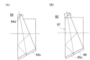
図4(A)、図4(B)及び図5(A)~図5(D)は、前記ダイクロイックプリズム38の変形例を示している。 4(A), FIG. 4(B), and FIGS. 5(A) to 5(D) show modified examples of the dichroic prism 38.

図4(A)に示されるダイクロイックプリズム66は、第3面66cで反射された反射測距光の前記受光光軸36及び反射追尾光の前記追尾受光光軸44に対する第4面66dの傾斜方向が異なっている。分離面としての前記第4面66dは反射追尾光を透過させ、反射測距光を前記視準部26に向って反射させる様に構成されている。その他の構成については、前記ダイクロイックプリズムと同等の構成となっている。 The dichroic prism 66 shown in FIG. 4(A) has an inclination direction of the fourth surface 66d with respect to the light receiving optical axis 36 of the reflected ranging light reflected by the third surface 66c and the tracking receiving optical axis 44 of the reflected tracking light. are different. The fourth surface 66d serving as a separating surface is configured to transmit the reflected tracking light and reflect the reflected distance measuring light toward the collimating section 26. The other configurations are the same as those of the dichroic prism described above.

図4(B)に示されるダイクロイックプリズム67は、2つの三角プリズムを組合わせた四角プリズムを第3プリズム69として構成している。又、該第3プリズム69の2つの三角プリズムの境界面は、ダイクロイックフィルタ膜が設けられた分離面としての第4面67dとなっている。該第4面67dを介して、反射測距光と反射追尾光とが分離される様構成されている。 The dichroic prism 67 shown in FIG. 4B has a third prism 69 that is a square prism that is a combination of two triangular prisms. Further, the boundary surface between the two triangular prisms of the third prism 69 is a fourth surface 67d serving as a separation surface provided with a dichroic filter film. The reflected distance measuring light and the reflected tracking light are separated via the fourth surface 67d.

上記した様に、前記ダイクロイックプリズム67は、内部に前記第4面67dを有する四角プリズムとなっている。従って、第1プリズム68に対する前記第3プリズム69の取付け位置を変更することで、反射測距光の反射方向を反射追尾光の前記追尾受光光軸44を中心とした任意の方向に変更することができる。 As described above, the dichroic prism 67 is a square prism having the fourth surface 67d inside. Therefore, by changing the mounting position of the third prism 69 with respect to the first prism 68, the direction of reflection of the reflected ranging light can be changed to any direction centered on the tracking receiving optical axis 44 of the reflected tracking light. I can do it.

図5(A)に示されるダイクロイックプリズム71は、第2プリズム73と第3プリズム74とが、それぞれ第1プリズム72の第2面71bに貼付けられ、一体化されている。前記ダイクロイックプリズム71では、可視光又は赤色の一部を除く可視光の分離面としての前記第2面71bのうち、前記第3プリズム74との境界面が分離面としての第4面71dとなっている。 In the dichroic prism 71 shown in FIG. 5A, a second prism 73 and a third prism 74 are each attached to the second surface 71b of the first prism 72 and are integrated. In the dichroic prism 71, the interface with the third prism 74 of the second surface 71b, which serves as a separation surface for visible light or visible light excluding a part of red color, serves as a fourth surface 71d, which serves as a separation surface. ing.

第1面71aに入射した反射測距光、反射追尾光、可視光の主光線40は、前記第1面71aを透過し、前記第2面71bに入射する。該第2面71bは、可視光又は赤色の一部を除く可視光を透過させ、反射測距光と反射追尾光とを反射させる。即ち、前記主光線40から可視光又は赤色の一部を除く可視光を分離する。分離された可視光又は赤色の一部を除く可視光は、第5面71eを透過して前記視準部26に入射する。又、前記第2面71bで反射された反射測距光と反射追尾光は、前記第1面71a、第3面71c、前記第2面71b、前記第1面71aで順次反射され、前記第4面71dに入射する。 The reflected ranging light, the reflected tracking light, and the principal ray 40 of visible light incident on the first surface 71a pass through the first surface 71a and enter the second surface 71b. The second surface 71b transmits visible light or visible light excluding a portion of red, and reflects reflected distance measuring light and reflected tracking light. That is, visible light or visible light excluding a part of the red color is separated from the principal ray 40. The separated visible light or the visible light excluding a part of the red color passes through the fifth surface 71e and enters the collimating section 26. Further, the reflected ranging light and the reflected tracking light reflected by the second surface 71b are sequentially reflected by the first surface 71a, the third surface 71c, the second surface 71b, and the first surface 71a. The light is incident on the fourth surface 71d.

該第4面71dは、反射測距光を反射させると共に、反射追尾光を透過させる。即ち、前記第4面71dは反射測距光と反射追尾光とを分離する。前記第4面71dで反射された反射測距光は前記第1面71aを透過し、前記受光部39に入射する。又、前記第4面71dを透過した反射追尾光は第6面71fを透過し、前記撮像素子45に入射する。 The fourth surface 71d reflects the reflected distance measuring light and transmits the reflected tracking light. That is, the fourth surface 71d separates the reflected distance measuring light and the reflected tracking light. The reflected distance measuring light reflected by the fourth surface 71d passes through the first surface 71a and enters the light receiving section 39. Further, the reflected tracking light that has passed through the fourth surface 71d passes through the sixth surface 71f and enters the image pickup device 45.

前記ダイクロイックプリズム71では、反射測距光と反射追尾光を前記ダイクロイックプリズム71内で5回内部反射させた後、前記第4面71dで分離する様構成される。従って、前記測距光受光部23及び前記追尾光受光部25の光軸方向の長さを更に短くすることができる。 The dichroic prism 71 is configured to internally reflect the reflected ranging light and the reflected tracking light five times within the dichroic prism 71, and then separate them at the fourth surface 71d. Therefore, the lengths of the ranging light receiving section 23 and the tracking light receiving section 25 in the optical axis direction can be further shortened.

図5(B)に示されるダイクロイックプリズム75は、第3プリズム78が第1プリズム76の下面に貼付けられ、第2プリズム77が前記第1プリズム76の第2面75bと前記第3プリズム78に掛渡って貼付けられ、一体化されている。前記ダイクロイックプリズム75では、前記第3プリズム78の紙面に対して下側の面が第3面75cとなり、前記第3面75cと前記第3プリズム78との境界面が第4面75dとなっている。又、前記第1プリズム76の紙面に対して上側の面が第6面75fとなっている。 In the dichroic prism 75 shown in FIG. 5(B), a third prism 78 is attached to the lower surface of the first prism 76, and a second prism 77 is attached to the second surface 75b of the first prism 76 and the third prism 78. It is pasted across and integrated. In the dichroic prism 75, the lower surface of the third prism 78 with respect to the paper surface is a third surface 75c, and the boundary surface between the third surface 75c and the third prism 78 is a fourth surface 75d. There is. Further, the upper surface of the first prism 76 with respect to the plane of the drawing is a sixth surface 75f.

第1面75aに入射した反射測距光、反射追尾光、可視光の主光線40は、前記第1面75aを透過し、可視光又は赤色の一部を除く可視光の分離面としての前記第2面75bに入射する。該第2面75bは、可視光又は赤色の一部を除く可視光を透過させ、反射測距光と反射追尾光とを反射させる。又、前記第2面75bで反射された反射測距光と反射追尾光は、前記第1面75aで反射され、分離面としての前記第4面75dに入射する。 The reflected ranging light, the reflected tracking light, and the principal ray 40 of visible light that have entered the first surface 75a are transmitted through the first surface 75a, and the reflected distance measuring light, the reflected tracking light, and the principal ray 40 of visible light are transmitted through the first surface 75a. The light is incident on the second surface 75b. The second surface 75b transmits visible light or visible light excluding a portion of red, and reflects reflected distance measuring light and reflected tracking light. Further, the reflected ranging light and the reflected tracking light reflected by the second surface 75b are reflected by the first surface 75a and enter the fourth surface 75d as a separation surface.

該第4面75dは、反射測距光を反射し、反射追尾光を透過する。前記第4面75dで反射された反射測距光は、前記第6面75fを透過して前記受光部39に入射する。又、前記第4面75dを透過した反射追尾光は、前記第3面75c、前記第2面75b、前記第1面75a、前記第2面75bで順次反射され、前記第1面75aを透過して前記撮像素子45に受光される。 The fourth surface 75d reflects the reflected distance measuring light and transmits the reflected tracking light. The reflected ranging light reflected by the fourth surface 75d passes through the sixth surface 75f and enters the light receiving section 39. Further, the reflected tracking light that has passed through the fourth surface 75d is sequentially reflected by the third surface 75c, the second surface 75b, the first surface 75a, and the second surface 75b, and is transmitted through the first surface 75a. The light is then received by the image sensor 45.

前記ダイクロイックプリズム75では、反射追尾光が前記ダイクロイックプリズム75内で6回内部反射する様構成されている。従って、前記追尾光受光部25の光軸方向の長さを更に短くすることができる。 The dichroic prism 75 is configured such that the reflected tracking light is internally reflected six times within the dichroic prism 75. Therefore, the length of the tracking light receiving section 25 in the optical axis direction can be further shortened.

図5(C)に示されるダイクロイックプリズム79は、第1面79aで反射された反射測距光及び反射追尾光の光軸に対する第4面79dの傾斜方向が異なることを除き、前記ダイクロイックプリズム75と略同等の構成となっている。 The dichroic prism 79 shown in FIG. 5(C) is different from the dichroic prism 75 except that the direction of inclination of the fourth surface 79d with respect to the optical axis of the reflected ranging light and the reflected tracking light reflected by the first surface 79a is different. It has almost the same configuration as .

可視光又は赤色の一部を除く可視光の分離面としての第2面79bで反射された反射測距光と反射追尾光は、前記第1面79aで反射され、分離面としての前記第4面79dに入射する。該第4面79dは、反射測距光を反射し、反射追尾光を透過する。 The reflected ranging light and the reflected tracking light reflected on the second surface 79b serving as a separation surface for visible light or visible light excluding a part of red are reflected on the first surface 79a, and the reflected distance measuring light and reflected tracking light are reflected on the first surface 79a, and The light is incident on the surface 79d. The fourth surface 79d reflects the reflected distance measuring light and transmits the reflected tracking light.

前記第4面75dで反射された反射測距光は、前記第2面79b、前記第1面79a、前記第2面79bで順次反射された後、前記第1面79aを透過して前記受光部39に受光される。又、前記第4面79dを透過した反射追尾光は、前記第3面79cで反射された後、第6面79fを透過して前記撮像素子45に受光される。 The reflected distance measuring light reflected by the fourth surface 75d is sequentially reflected by the second surface 79b, the first surface 79a, and the second surface 79b, and then passes through the first surface 79a and reaches the received light. The light is received by the section 39. Further, the reflected tracking light that has passed through the fourth surface 79d is reflected by the third surface 79c, and then transmitted through the sixth surface 79f and is received by the image pickup device 45.

前記ダイクロイックプリズム79では、反射測距光が前記ダイクロイックプリズム79内で6回内部反射する様構成されている。従って、前記測距光受光部23の光軸方向の長さを更に短くすることができる。 The dichroic prism 79 is configured such that the reflected distance measuring light is internally reflected six times within the dichroic prism 79. Therefore, the length of the distance measuring light receiving section 23 in the optical axis direction can be further shortened.

図5(D)に示されるダイクロイックプリズム81は、前記ダイクロイックプリズム71と同様に、第1プリズム82の第2面81bに第2プリズム83と第3プリズム84とがそれぞれ貼付けられ、一体化されている。又、前記第3プリズム84の紙面に対して上側の面及び前記第1プリズム82の紙面に対して上側の面は、それぞれ反射防止膜が設けられた第6面81fとなっている。 The dichroic prism 81 shown in FIG. 5(D), like the dichroic prism 71, has a second prism 83 and a third prism 84 attached to the second surface 81b of the first prism 82 and is integrated. There is. Further, the surface of the third prism 84 on the upper side with respect to the paper surface and the surface of the first prism 82 on the upper side with respect to the paper surface of the drawing form a sixth surface 81f provided with an antireflection film, respectively.

第1面81aに入射した反射測距光、反射追尾光、可視光の主光線40は、前記第1面81aを透過し、可視光又は赤色の一部を除く可視光の分離面としての前記第2面81bに入射する。該第2面81bは、可視光又は赤色の一部を除く可視光を透過させ、反射測距光と反射追尾光とを反射させる。又、該第2面81bで反射された反射測距光と反射追尾光は、前記第1面81a、第3面81c、前記第1面81aで順次反射され、分離面としての第4面81dに入射する。 The reflected distance measuring light, the reflected tracking light, and the principal ray 40 of visible light that have entered the first surface 81a are transmitted through the first surface 81a, and the reflected distance measuring light, the reflected tracking light, and the principal ray 40 of visible light are transmitted through the first surface 81a. The light is incident on the second surface 81b. The second surface 81b transmits visible light or visible light excluding a portion of red, and reflects reflected distance measuring light and reflected tracking light. Further, the reflected ranging light and the reflected tracking light reflected by the second surface 81b are sequentially reflected by the first surface 81a, the third surface 81c, and the first surface 81a, and are reflected by the fourth surface 81d as a separating surface. incident on .

該第4面81dは、反射測距光を反射し、反射追尾光を透過する。前記第4面81dで反射された反射測距光は、前記第6面81fを透過して前記受光部39に受光される。又、前記第4面81dを透過した反射追尾光は、前記第6面81fを透過して前記撮像素子45に受光される。 The fourth surface 81d reflects the reflected distance measuring light and transmits the reflected tracking light. The reflected distance measuring light reflected by the fourth surface 81d passes through the sixth surface 81f and is received by the light receiving section 39. Further, the reflected tracking light that has passed through the fourth surface 81d passes through the sixth surface 81f and is received by the image pickup device 45.

尚、図4(A)、図4(B)、図5(A)~図5(D)に於いても、第4面の反射側に前記追尾光受光部25を配置し、第4面の透過側に前記測距光受光部23を配置してもよいのは言う迄もない。 4(A), FIG. 4(B), and FIG. 5(A) to FIG. 5(D), the tracking light receiving section 25 is arranged on the reflective side of the fourth surface, and Needless to say, the distance measuring light receiving section 23 may be arranged on the transmission side of the lens.

次に、図6に於いて、本発明の第2の実施例について説明する。尚、図10中、図3中と同等のものには同符号を付し、その説明を省略する。 Next, referring to FIG. 6, a second embodiment of the present invention will be described. In FIG. 10, the same parts as those in FIG. 3 are given the same reference numerals, and the explanation thereof will be omitted.

第2の実施例に於けるダイクロイックプリズム80は、第1の実施例に於けるダイクロイックプリズム38に色ガラス90を追加した構成となっている。又、前記ダイクロイックプリズム80以外の構成については、第1の実施例と同様となっている。 The dichroic prism 80 in the second embodiment has a structure in which a colored glass 90 is added to the dichroic prism 38 in the first embodiment. Further, the configuration other than the dichroic prism 80 is the same as that of the first embodiment.

前記ダイクロイックプリズム80は、第1プリズム100と第2プリズム85と第3プリズム86とを有し、前記第1プリズム100の紙面に対して下側の面に前記色ガラス90が貼付けられ、一体化されている。 The dichroic prism 80 has a first prism 100, a second prism 85, and a third prism 86, and the colored glass 90 is attached to the lower surface of the first prism 100 with respect to the plane of the paper, so that they are integrated. has been done.

第2の実施例に於いては、前記第1プリズム100の対物レンズ37(図2参照)と対向する面が第1面87となり、前記第1プリズム100と前記第2プリズム85の境界面が第2面88となり、前記色ガラス90の下面、即ち前記第1プリズム100と前記色ガラス90の境界面と対向する面が第3面89となり、前記第1プリズム100と前記第3プリズム86との境界面が第4面91となる。又、前記第2プリズム85の紙面に対して右側の面が第5面92となり、前記第3プリズム86の紙面に対して上側の面が第6面93となる。尚、前記第3面89は、反射膜が設けられた反射面となっている。 In the second embodiment, the surface of the first prism 100 facing the objective lens 37 (see FIG. 2) is the first surface 87, and the interface between the first prism 100 and the second prism 85 is the first surface 87. The second surface 88 is the lower surface of the colored glass 90, that is, the surface facing the interface between the first prism 100 and the colored glass 90 is the third surface 89. The boundary surface becomes the fourth surface 91. Further, the surface of the second prism 85 on the right side with respect to the paper surface is a fifth surface 92, and the surface of the third prism 86 on the upper side with respect to the paper surface is a sixth surface 93. Note that the third surface 89 is a reflective surface provided with a reflective film.

前記第1面87に入射した反射測距光、反射追尾光、可視光の主光線40は、前記第1面87を透過し、可視光又は赤色の一部を除く可視光の分離面としての前記第2面88に入射する。該第2面88は、可視光又は赤色の一部を除く可視光を透過させ、反射測距光と反射追尾光とを反射させる。前記第2面88を透過した可視光又は赤色の一部を除く可視光は、前記第5面92を透過して視準部26(図2参照)に入射する。又、前記第2面88で反射された反射測距光と反射追尾光は、前記第1面87、前記第3面89で順次反射され、分離面としての前記第4面91に入射する。 The reflected distance measuring light, the reflected tracking light, and the principal ray 40 of visible light incident on the first surface 87 are transmitted through the first surface 87, and serve as a separating surface for visible light or visible light excluding a part of red. The light is incident on the second surface 88 . The second surface 88 transmits visible light or visible light excluding a portion of red, and reflects reflected distance measuring light and reflected tracking light. The visible light that has passed through the second surface 88 or the visible light excluding a portion of the red color passes through the fifth surface 92 and enters the collimation section 26 (see FIG. 2). Further, the reflected distance measuring light and the reflected tracking light reflected by the second surface 88 are sequentially reflected by the first surface 87 and the third surface 89, and are incident on the fourth surface 91 as a separating surface.

該第4面91は、反射測距光を反射し、反射追尾光を透過する。前記第4面91で反射された反射測距光は、前記第1面87を透過して受光部39(図2参照)に受光される。又、前記第4面91を透過した反射追尾光は、前記第6面93を透過して撮像素子45(図2参照)に受光される。 The fourth surface 91 reflects the reflected distance measuring light and transmits the reflected tracking light. The reflected distance measuring light reflected by the fourth surface 91 passes through the first surface 87 and is received by the light receiving section 39 (see FIG. 2). Further, the reflected tracking light that has passed through the fourth surface 91 passes through the sixth surface 93 and is received by the image sensor 45 (see FIG. 2).

反射測距光と反射追尾光は、前記第3面89で反射される際に前記色ガラス90内を通過する。該色ガラス90内を通過する過程で、前記色ガラス90の吸収により、反射測距光と反射追尾光の外乱光が減衰又は除去される。 The reflected distance measuring light and the reflected tracking light pass through the colored glass 90 when being reflected by the third surface 89 . During the process of passing through the colored glass 90, the disturbance light of the reflected ranging light and the reflected tracking light is attenuated or removed by the absorption of the colored glass 90.

第2の実施例では、前記ダイクロイックプリズム80に前記色ガラス90を設けることで、反射測距光と反射追尾光の外乱光を減衰又は除去している。従って、測距結果、追尾結果から外乱光の影響を低減又は除去できるので、測距精度、追尾精度を向上させることができる。色ガラスを設けずに薄膜により外乱光の影響を低減又は除去も可能だが、外乱光が吸収されずに反射され、影響が僅かに残る場合もある。 In the second embodiment, the dichroic prism 80 is provided with the colored glass 90 to attenuate or eliminate the disturbance light of the reflected ranging light and the reflected tracking light. Therefore, it is possible to reduce or eliminate the influence of ambient light from the distance measurement results and tracking results, so that distance measurement accuracy and tracking accuracy can be improved. Although it is possible to reduce or eliminate the influence of ambient light by using a thin film without providing colored glass, there are cases where the ambient light is not absorbed but is reflected, leaving a slight influence.

尚、前記色ガラス90は、前記撮像素子45からできるだけ離れた位置に設けるのが望ましい。前記色ガラス90に内部欠陥がある場合には、前記撮像素子45に前記色ガラス90の内部欠陥が映込み、追尾精度に影響を及ぼすからである。仮に、前記色ガラス90を前記撮像素子45の近くに設ける場合には、前記色ガラス90の内部欠陥についての選別操作が別途必要となる。 Note that it is desirable that the colored glass 90 be provided at a position as far away from the image sensor 45 as possible. This is because if the colored glass 90 has an internal defect, the internal defect of the colored glass 90 will be reflected in the image sensor 45, which will affect tracking accuracy. If the colored glass 90 is provided near the image pickup device 45, a separate screening operation for internal defects in the colored glass 90 is required.

又、前記色ガラス90の内部欠陥が測距結果に影響を及ぼすことはない為、前記受光部39に対する前記色ガラス90の位置の制約はなく、任意の位置に設けることができる。 Moreover, since internal defects in the colored glass 90 do not affect the distance measurement results, there is no restriction on the position of the colored glass 90 with respect to the light receiving section 39, and it can be provided at any position.

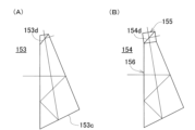
図7(A)、図7(B)、図8(A)~図8(D)、図9(A)、図9(B)は、前記ダイクロイックプリズム80の変形例を示している。 7(A), FIG. 7(B), FIG. 8(A) to FIG. 8(D), FIG. 9(A), and FIG. 9(B) show modified examples of the dichroic prism 80.

図7(A)に示されるダイクロイックプリズム94は、第3面94cで反射された反射測距光と反射追尾光の光軸に対する第4面94dの傾斜方向が異なっている。反射追尾光は分離面としての前記第4面94dを透過し、反射測距光は前記第4面94dにより前記視準部26に向って反射される様に構成されている。その他の構成については、前記ダイクロイックプリズム80と同等の構成となっている。 In the dichroic prism 94 shown in FIG. 7A, the direction of inclination of the fourth surface 94d with respect to the optical axis of the reflected ranging light and the reflected tracking light reflected by the third surface 94c is different. The reflected tracking light is configured to pass through the fourth surface 94d serving as a separation surface, and the reflected distance measuring light is reflected toward the collimation section 26 by the fourth surface 94d. The other configurations are the same as those of the dichroic prism 80 described above.

図7(B)に示されるダイクロイックプリズム95は、図4(B)に示されるダイクロイックプリズム66の紙面に対して下側の面に、色ガラス96を設けた構成となっている。又、第1プリズム97と前記色ガラス96との境界面と対向する面を第3面95cとしている。その他の構成については、前記ダイクロイックプリズム66と同様の構成となっている。 The dichroic prism 95 shown in FIG. 7(B) has a structure in which colored glass 96 is provided on the lower surface of the dichroic prism 66 shown in FIG. 4(B) with respect to the paper surface. Further, the surface facing the boundary surface between the first prism 97 and the colored glass 96 is defined as a third surface 95c. The rest of the structure is similar to that of the dichroic prism 66.

図8(A)に示されるダイクロイックプリズム98は、図5(A)に示されるダイクロイックプリズム71と略同等の構成である。第2プリズム101と第3プリズム102とが、それぞれ分離面としての第2面98bに貼付けられている。又、第1プリズム99の紙面に対して下側の面に色ガラス103が貼付けられ、一体化されている。該色ガラス103の前記第1プリズム99との境界面と対向する面が第3面98cとなっている。その他の構成については、前記ダイクロイックプリズム71と同様の構成となっている。 Dichroic prism 98 shown in FIG. 8(A) has substantially the same configuration as dichroic prism 71 shown in FIG. 5(A). The second prism 101 and the third prism 102 are each attached to a second surface 98b serving as a separation surface. Further, colored glass 103 is attached to the lower surface of the first prism 99 with respect to the paper surface, and is integrated. The surface of the colored glass 103 that faces the boundary surface with the first prism 99 is a third surface 98c. The rest of the structure is similar to that of the dichroic prism 71 described above.

図8(B)に示されるダイクロイックプリズム104は、図5(B)に示されるダイクロイックプリズム75と略同等の構成となっている。第1プリズム105の紙面に対して下側の面に第3プリズム107が貼付けられ、前記第1プリズム105の第2面104bに第2プリズム106が貼付けられ、前記第3プリズム107の前記第1プリズム105との境界面と対向する面に色ガラス108が貼付けられ、一体化されている。前記ダイクロイックプリズム104では、前記第1プリズム105と前記第3プリズム107との境界面が分離面としての第4面104dであり、前記色ガラス108の前記第4面104dと対向する面が第3面104cとなっている。 The dichroic prism 104 shown in FIG. 8(B) has substantially the same configuration as the dichroic prism 75 shown in FIG. 5(B). A third prism 107 is attached to the lower surface of the first prism 105 with respect to the paper surface, a second prism 106 is attached to the second surface 104b of the first prism 105, and the first prism 107 of the third prism 107 Colored glass 108 is attached to the surface facing the boundary surface with prism 105 and is integrated. In the dichroic prism 104, the interface between the first prism 105 and the third prism 107 is a fourth surface 104d serving as a separation surface, and the surface of the colored glass 108 opposite to the fourth surface 104d is a third surface. This is a surface 104c.

反射測距光は、第4面104dで反射され第6面104fを透過する。一方で、反射追尾光は、前記第4面104dを透過し、前記第3面104cで反射される過程で前記色ガラス108を通過し、外乱光が減衰又は除去される。従って、外乱光が受光結果に影響を及ぼすことはなく、追尾精度を向上させることができる。 The reflected distance measuring light is reflected by the fourth surface 104d and transmitted through the sixth surface 104f. On the other hand, the reflected tracking light passes through the colored glass 108 in the process of being transmitted through the fourth surface 104d and reflected by the third surface 104c, and the disturbance light is attenuated or removed. Therefore, the disturbance light does not affect the light reception result, and tracking accuracy can be improved.

図8(C)に示されるダイクロイックプリズム109は、図8(B)に示されるダイクロイックプリズム104の変形例となっている。前記ダイクロイックプリズム109では、第1プリズム111の紙面に対して下面に色ガラス112が貼付けられ、該色ガラス112に第3プリズム113が貼付けられ、一体化されている。即ち、前記第1プリズム111と前記第3プリズム113との間に前記色ガラス112が設けられている。 Dichroic prism 109 shown in FIG. 8(C) is a modification of dichroic prism 104 shown in FIG. 8(B). In the dichroic prism 109, a colored glass 112 is attached to the lower surface of the first prism 111 relative to the paper surface, and a third prism 113 is attached to the colored glass 112 to be integrated. That is, the colored glass 112 is provided between the first prism 111 and the third prism 113.

前記ダイクロイックプリズム109では、前記色ガラス112と前記第3プリズム113との境界面が分離面としての第4面109dとなり、前記第3プリズム113の前記第4面109dと対向する面が第3面109cとなっている。 In the dichroic prism 109, the interface between the colored glass 112 and the third prism 113 is a fourth surface 109d serving as a separation surface, and the surface of the third prism 113 opposite to the fourth surface 109d is a third surface. It is 109c.

前記ダイクロイックプリズム109では、反射追尾光だけではなく、反射測距光の外乱光も減衰又は除去できるので、測距精度、追尾精度を向上させることができる。 The dichroic prism 109 can attenuate or remove not only the reflected tracking light but also the disturbance light of the reflected ranging light, so that ranging accuracy and tracking accuracy can be improved.

図8(D)に示されるダイクロイックプリズム114は、第1面114aで反射された反射測距光及び反射追尾光の光軸に対する第4面114dの傾斜方向が異なることを除き、図8(B)に示される前記ダイクロイックプリズム104と略同等の構成となっている。 The dichroic prism 114 shown in FIG. 8(D) is different from the one shown in FIG. ) has substantially the same configuration as the dichroic prism 104 shown in FIG.

反射測距光は、分離面としての前記第4面114dで反射される。一方で、反射追尾光は、前記第4面114dを透過し、前記第3面114cで反射される過程で前記色ガラス115を通過し、外乱光が減衰又は除去される。従って、外乱光が受光結果に影響を及ぼすことはなく、追尾精度を向上させることができる。 The reflected distance measuring light is reflected by the fourth surface 114d serving as the separation surface. On the other hand, the reflected tracking light passes through the colored glass 115 in the process of being transmitted through the fourth surface 114d and reflected by the third surface 114c, and the disturbance light is attenuated or removed. Therefore, the disturbance light does not affect the light reception result, and tracking accuracy can be improved.

図9(A)に示されるダイクロイックプリズム116は、図8(D)に示される前記ダイクロイックプリズム114の変形例となっている。前記ダイクロイックプリズム116では、第1プリズム117の紙面に対して下面に色ガラス118が貼付けられ、該色ガラス118に第3プリズム119が貼付けられ、一体化されている。即ち、前記第1プリズム117と前記第3プリズム119との間に前記色ガラス118が設けられている。 The dichroic prism 116 shown in FIG. 9(A) is a modification of the dichroic prism 114 shown in FIG. 8(D). In the dichroic prism 116, a colored glass 118 is attached to the lower surface of the first prism 117 relative to the paper surface, and a third prism 119 is attached to the colored glass 118 to be integrated. That is, the colored glass 118 is provided between the first prism 117 and the third prism 119.

前記ダイクロイックプリズム116では、前記色ガラス118と前記第3プリズム119との境界面が分離面としての第4面116dとなり、前記第3プリズム119の前記第4面116dと対向する面が第3面116cとなっている。 In the dichroic prism 116, the interface between the colored glass 118 and the third prism 119 is a fourth surface 116d serving as a separation surface, and the surface of the third prism 119 opposite to the fourth surface 116d is a third surface. It is 116c.

前記ダイクロイックプリズム116では、反射追尾光だけではなく、反射測距光の外乱光も減衰又は除去できるので、測距精度、追尾精度を向上させることができる。 The dichroic prism 116 can attenuate or remove not only the reflected tracking light but also the disturbance light of the reflected ranging light, so that ranging accuracy and tracking accuracy can be improved.

図9(B)に示されるダイクロイックプリズム121は、図5(D)に示される前記ダイクロイックプリズム81の紙面に対して下側の面に、色ガラス122を設けた構成となっている。又、該色ガラス122の第1プリズム123との境界面と対向する面を第3面121cとしている。その他の構成については、前記ダイクロイックプリズム81と同様の構成となっている。 The dichroic prism 121 shown in FIG. 9(B) has a structure in which colored glass 122 is provided on the lower surface of the dichroic prism 81 shown in FIG. 5(D) with respect to the paper surface. Further, the surface of the colored glass 122 that faces the boundary surface with the first prism 123 is defined as a third surface 121c. The rest of the structure is similar to that of the dichroic prism 81 described above.

尚、図7(A)、図7(B)、図8(A)~図8(D)、図9(A)、図9(B)に於いても、第4面の反射側に前記追尾光受光部25を配置し、第4面の透過側に前記測距光受光部23を配置してもよいのは言う迄もない。 In addition, in FIG. 7(A), FIG. 7(B), FIG. 8(A) to FIG. 8(D), FIG. 9(A), and FIG. 9(B), the above-mentioned It goes without saying that the tracking light receiving section 25 may be arranged and the distance measuring light receiving section 23 may be arranged on the transmission side of the fourth surface.

次に、図10に於いて、本発明の第3の実施例について説明する。尚、図10中、図3中と同等のものには同符号を付し、その説明を省略する。 Next, referring to FIG. 10, a third embodiment of the present invention will be described. In FIG. 10, the same parts as those in FIG. 3 are given the same reference numerals, and the explanation thereof will be omitted.

第3の実施例は、測量装置本体3(図1参照)から追尾光射出部24(図2参照)と追尾光受光部25(図2参照)を取除いた構成となっている。その他の構成については第1の実施例と同様である。 The third embodiment has a configuration in which the tracking light emitting section 24 (see FIG. 2) and the tracking light receiving section 25 (see FIG. 2) are removed from the surveying device main body 3 (see FIG. 1). The other configurations are the same as those of the first embodiment.

第3の実施例に於けるダイクロイックプリズム124は、第3プリズムを有しておらず、第1プリズム125と第2プリズム126とが組み合わされ、一体化された構成となっている。 The dichroic prism 124 in the third embodiment does not have a third prism, but has an integrated structure in which a first prism 125 and a second prism 126 are combined.

前記第1プリズム125の対物レンズ37(図2参照)と対向する面が第1面127となり、前記第1プリズム125と前記第2プリズム126の境界面が第2面128となり、前記第1プリズム125の紙面に対して下側の面が第3面129となる。又、前記第2プリズム126の紙面に対して右側の面が第5面131となり、前記第1プリズム125の紙面に対して上側の面が第6面となる。 The surface of the first prism 125 that faces the objective lens 37 (see FIG. 2) becomes the first surface 127, and the interface between the first prism 125 and the second prism 126 becomes the second surface 128, and the first prism The surface below the paper surface of 125 is the third surface 129. Further, the surface of the second prism 126 on the right side with respect to the paper surface is the fifth surface 131, and the surface of the first prism 125 on the upper side with respect to the paper surface is the sixth surface.

前記第1面127に入射した反射測距光、可視光の主光線40は、前記第1面127を透過し、可視光又は赤色の一部を除く可視光の分離面としての前記第2面128に入射する。該第2面128は、可視光又は赤色の一部を除く可視光を透過させ、反射測距光を反射させる。前記第2面128を透過した可視光又は赤色の一部を除く可視光は、前記第5面131を透過して視準部26(図2参照)に入射する。又、前記第2面128で反射された反射測距光は、前記第1面127、前記第3面129で順次反射され、前記第6面132を透過する。該第6面132を透過した反射測距光は、受光部39(図2参照)に受光される。 The principal ray 40 of the reflected ranging light and visible light incident on the first surface 127 is transmitted through the first surface 127, and the second surface serves as a separating surface for visible light or visible light excluding a part of red. 128. The second surface 128 transmits visible light or visible light excluding a portion of red, and reflects reflected ranging light. The visible light that has passed through the second surface 128 or the visible light excluding a portion of the red color passes through the fifth surface 131 and enters the collimation unit 26 (see FIG. 2). Further, the reflected distance measuring light reflected by the second surface 128 is sequentially reflected by the first surface 127 and the third surface 129, and is transmitted through the sixth surface 132. The reflected distance measuring light transmitted through the sixth surface 132 is received by the light receiving section 39 (see FIG. 2).

第3の実施例に於いても、反射測距光が前記ダイクロイックプリズム124内で3回内部反射される構成となっているので、前記対物レンズ37の焦点距離分の光路長を確保することができる。 In the third embodiment as well, since the reflected distance measuring light is internally reflected three times within the dichroic prism 124, it is possible to ensure an optical path length equivalent to the focal length of the objective lens 37. can.

従って、前記測距光受光部23の光軸方向の長さを小さくすることができるので、前記距離測定部19の光学系の小型化が図れると共に、測量装置全体の小型化を図ることができる。 Therefore, since the length of the distance measuring light receiving section 23 in the optical axis direction can be reduced, the optical system of the distance measuring section 19 can be downsized, and the entire surveying apparatus can be downsized. .

図11(A)~図11(D)、図12(A)~図12(D)は、前記ダイクロイックプリズム124の変形例を示している。 11(A) to 11(D) and FIG. 12(A) to FIG. 12(D) show modified examples of the dichroic prism 124.

図11(A)に示されるダイクロイックプリズム133は、第6面133fに反射膜が設けられている。又、該第6面133fは反射測距光の光軸に対して傾斜され、反射測距光を対物レンズ37(図2参照)側に反射させる様構成されている。その他の構成については、前記ダイクロイックプリズム124と同様となっている。 In the dichroic prism 133 shown in FIG. 11(A), a reflective film is provided on the sixth surface 133f. Further, the sixth surface 133f is inclined with respect to the optical axis of the reflected distance measuring light, and is configured to reflect the reflected distance measuring light toward the objective lens 37 (see FIG. 2). The other configurations are the same as those of the dichroic prism 124.

尚、前記第6面133fに対する反射測距光の入射角が臨界角以上である場合には、反射膜は省略してもよい。 Incidentally, if the angle of incidence of the reflected ranging light with respect to the sixth surface 133f is equal to or greater than the critical angle, the reflective film may be omitted.

図11(B)に示されるダイクロイックプリズム134は、反射測距光の光軸に対する第6面134fの傾斜方向が異なることを除き、前記ダイクロイックプリズム133と同様の構成となっている。 The dichroic prism 134 shown in FIG. 11(B) has the same configuration as the dichroic prism 133 except that the direction of inclination of the sixth surface 134f with respect to the optical axis of the reflected ranging light is different.

前記ダイクロイックプリズム134は、反射測距光を視準部26(図2参照)に向って反射させる様に構成されている。 The dichroic prism 134 is configured to reflect the reflected ranging light toward the collimating section 26 (see FIG. 2).

図11(C)に示されるダイクロイックプリズム135は、前記ダイクロイックプリズム124の前記第1プリズム125の紙面に対して上側の面に三角プリズム136を貼付け一体化させた構成となっている。又、該三角プリズム136の紙面に対して左側の面が反射測距光の光軸に対して傾斜した第6面135fとなっており、該第6面135fにより反射測距光が反射される様に構成されている。 The dichroic prism 135 shown in FIG. 11(C) has a structure in which a triangular prism 136 is attached and integrated with the upper surface of the first prism 125 of the dichroic prism 124 with respect to the paper surface. In addition, the surface on the left side of the triangular prism 136 with respect to the plane of the drawing is a sixth surface 135f that is inclined with respect to the optical axis of the reflected distance measuring light, and the reflected distance measuring light is reflected by the sixth surface 135f. It is structured like this.

上記した様に、前記ダイクロイックプリズム135は、反射測距光を反射させる為の前記三角プリズム136を別途設けている。従って、第1プリズム137に対する前記三角プリズム136の取付け位置を変更することで、反射測距光の反射方向を反射測距光の光軸を中心とした任意の方向に変更することができる。 As described above, the dichroic prism 135 is additionally provided with the triangular prism 136 for reflecting the reflected distance measuring light. Therefore, by changing the mounting position of the triangular prism 136 with respect to the first prism 137, the direction of reflection of the reflected distance measuring light can be changed to any direction centered on the optical axis of the reflected distance measuring light.

図11(D)に示されるダイクロイックプリズム138では、第1面138aを透過し、可視光又は赤色の一部を除く可視光の分離面としての第2面138bで反射された反射測距光は、前記第1面138a、第3面138c、前記第2面138bで順次反射された後、第6面138fを透過して前記受光部39に受光される様構成されている。 In the dichroic prism 138 shown in FIG. 11(D), the reflected ranging light transmitted through the first surface 138a and reflected at the second surface 138b, which serves as a separation surface for visible light or visible light excluding a part of red light, is , after being sequentially reflected by the first surface 138a, the third surface 138c, and the second surface 138b, the light is transmitted through the sixth surface 138f and received by the light receiving section 39.

前記ダイクロイックプリズム138では、該ダイクロイックプリズム138内で反射測距光が4回内部反射する様構成されている。従って、前記測距光受光部23の光軸方向の長さを更に短くすることができ、該測距光受光部23の小型化を図ることができる。 The dichroic prism 138 is configured so that the reflected distance measuring light is internally reflected four times within the dichroic prism 138. Therefore, the length of the distance measuring light receiving section 23 in the optical axis direction can be further reduced, and the size of the distance measuring light receiving section 23 can be reduced.

図12(A)に示されるダイクロイックプリズム139は、第1面139aを透過し、可視光又は赤色の一部を除く可視光の分離面としての第2面139bで反射された反射測距光は、前記第1面139a、第3面139c、前記第2面139b、前記第1面139aで順次反射された後、第6面139fを透過して前記受光部39に受光される様構成されている。 In the dichroic prism 139 shown in FIG. 12(A), reflected ranging light that is transmitted through a first surface 139a and reflected at a second surface 139b, which serves as a separation surface for visible light or visible light excluding a part of red light, is transmitted through a first surface 139a. , after being sequentially reflected by the first surface 139a, the third surface 139c, the second surface 139b, and the first surface 139a, the light is transmitted through the sixth surface 139f and received by the light receiving section 39. There is.

前記ダイクロイックプリズム139では、該ダイクロイックプリズム139内で反射測距光が5回内部反射する様構成されている。従って、前記測距光受光部23の光軸方向の長さを更に短くすることができ、該測距光受光部23の小型化を図ることができる。 The dichroic prism 139 is configured such that the reflected distance measuring light is internally reflected five times within the dichroic prism 139. Therefore, the length of the distance measuring light receiving section 23 in the optical axis direction can be further reduced, and the size of the distance measuring light receiving section 23 can be reduced.

図12(B)に示されるダイクロイックプリズム141は、第1面141aを透過し、可視光又は赤色の一部を除く可視光の分離面としての第2面141bで反射された反射測距光は、前記第1面141a、第3面141c、前記第2面141b、前記第1面141a、前記第2面141bで順次反射された後、前記第1面141aを透過して前記受光部39に受光される様構成されている。 In the dichroic prism 141 shown in FIG. 12(B), the reflected ranging light transmitted through the first surface 141a and reflected at the second surface 141b, which serves as a separation surface for visible light or visible light excluding a part of red light, is transmitted through the first surface 141a. , the first surface 141a, the third surface 141c, the second surface 141b, the first surface 141a, and the second surface 141b. It is configured to receive light.

前記ダイクロイックプリズム141では、該ダイクロイックプリズム141内で反射測距光が6回内部反射する様構成されている。従って、前記測距光受光部23の光軸方向の長さを更に短くすることができ、該測距光受光部23の小型化を図ることができる。 The dichroic prism 141 is configured such that the reflected distance measuring light is internally reflected six times within the dichroic prism 141. Therefore, the length of the distance measuring light receiving section 23 in the optical axis direction can be further reduced, and the size of the distance measuring light receiving section 23 can be reduced.

図12(C)に示されるダイクロイックプリズム142は、第1面142aを透過し、可視光又は赤色の一部を除く可視光の分離面としての第2面142bで反射された反射測距光は、前記第1面142a、第3面142c、前記第1面141aで順次反射された後、第6面142fを透過して前記受光部39に受光される様構成されている。 In the dichroic prism 142 shown in FIG. 12(C), reflected ranging light that is transmitted through a first surface 142a and reflected at a second surface 142b, which serves as a separation surface for visible light or visible light excluding a part of red light, is transmitted through a first surface 142a. , the light is sequentially reflected by the first surface 142a, the third surface 142c, and the first surface 141a, and then transmitted through the sixth surface 142f and received by the light receiving section 39.

前記ダイクロイックプリズム142では、該ダイクロイックプリズム142内で反射測距光が4回内部反射する様構成されている。従って、前記ダイクロイックプリズム124に比べて前記測距光受光部23の光軸方向の長さを更に短くすることができ、該測距光受光部23の小型化を図ることができる。 The dichroic prism 142 is configured so that the reflected distance measuring light is internally reflected four times within the dichroic prism 142. Therefore, compared to the dichroic prism 124, the length of the distance measuring light receiving section 23 in the optical axis direction can be further shortened, and the distance measuring light receiving section 23 can be made smaller.

図12(D)に示されるダイクロイックプリズム143は、第1面143aを透過し、可視光又は赤色の一部を除く可視光の分離面としての第2面143bで反射された反射測距光は、前記第1面143a、第3面143c、前記第1面143a、前記第2面143bで順次反射された後、第6面143fを透過して前記受光部39に受光される様構成されている。 In the dichroic prism 143 shown in FIG. 12(D), the reflected ranging light transmitted through the first surface 143a and reflected at the second surface 143b, which serves as a separation surface for visible light or visible light excluding a part of red light, is transmitted through the first surface 143a. , the light is sequentially reflected by the first surface 143a, the third surface 143c, the first surface 143a, and the second surface 143b, and then transmitted through the sixth surface 143f and received by the light receiving section 39. There is.

前記ダイクロイックプリズム143では、該ダイクロイックプリズム143内で反射測距光が5回内部反射する様構成されている。従って、前記測距光受光部23の光軸方向の長さを更に短くすることができ、該測距光受光部23の小型化を図ることができる。 The dichroic prism 143 is configured so that the reflected distance measuring light is internally reflected five times within the dichroic prism 143. Therefore, the length of the distance measuring light receiving section 23 in the optical axis direction can be further reduced, and the size of the distance measuring light receiving section 23 can be reduced.

尚、反射測距光の前記第2面143bに対する2度目の入射角が臨界角以上である場合には、2度目に反射測距光が入射する部分のみ反射膜を取除いてもよい。 Incidentally, if the second incident angle of the reflected distance measuring light with respect to the second surface 143b is equal to or greater than the critical angle, the reflective film may be removed only from the portion where the reflected distance measuring light is incident for the second time.

尚、第3の実施例及び変形例を第2の実施例と組合わせ、色ガラスを追加してもよい。色ガラスの追加により、反射測距光の外乱光を減衰又は除去でき、測距精度を向上させることができる。 Note that the third embodiment and the modified example may be combined with the second embodiment, and colored glass may be added. By adding colored glass, it is possible to attenuate or remove the disturbance light of the reflected distance measuring light, and it is possible to improve the distance measuring accuracy.

次に、図13に於いて、本発明の第4の実施例について説明する。尚、図13中、図3中と同等のものには同符号を付し、その説明を省略する。 Next, referring to FIG. 13, a fourth embodiment of the present invention will be described. In FIG. 13, the same components as those in FIG. 3 are given the same reference numerals, and their explanations will be omitted.

第4の実施例は、測量装置本体3(図1参照)から視準部26(図2参照)を取除いた構成となっている。その他の構成については第1の実施例と同様である。但し、第4の実施例では、測距光と追尾光は、いずれも可視光又は近赤外光のどの波長であってもよい。 The fourth embodiment has a configuration in which the collimating section 26 (see FIG. 2) is removed from the surveying device main body 3 (see FIG. 1). The other configurations are the same as those of the first embodiment. However, in the fourth embodiment, both the ranging light and the tracking light may have any wavelength of visible light or near-infrared light.

第4の実施例に於けるダイクロイックプリズム144は、第2プリズムを有しておらず、第1プリズム145と第3プリズム146とが組み合わされ、一体化された構成となっている。 The dichroic prism 144 in the fourth embodiment does not have a second prism, but has an integrated configuration in which a first prism 145 and a third prism 146 are combined.

前記ダイクロイックプリズム144は、前記第1プリズム145の対物レンズ37(図2参照)と対向する面が第1面147となり、該第1面147と対向する面が第2面148となり、前記第1プリズム145の紙面に対して下側の面が第3面149となる。又、前記ダイクロイックプリズム144は、前記第1プリズム145と前記第3プリズム146との境界面が第4面151となり、前記第3プリズム146の紙面に対して上側の面が第6面152となっている。 The dichroic prism 144 has a first surface 147 that faces the objective lens 37 (see FIG. 2) of the first prism 145, a second surface 148 that faces the first surface 147, and a second surface 148 that faces the first surface 147. The lower surface of the prism 145 with respect to the plane of the drawing is the third surface 149 . Further, in the dichroic prism 144, the boundary surface between the first prism 145 and the third prism 146 is a fourth surface 151, and the surface of the third prism 146 on the upper side with respect to the paper surface is a sixth surface 152. ing.

前記第1面147を透過した反射測距光、反射追尾光の主光線40は、前記第2面148、前記第1面147、前記第3面149で順次反射された後、分離面としての前記第4面151に入射する。 The principal rays 40 of the reflected ranging light and the reflected tracking light that have passed through the first surface 147 are sequentially reflected by the second surface 148, the first surface 147, and the third surface 149, and then reflected as a separation surface. The light is incident on the fourth surface 151.

該第4面151に入射した反射測距光と反射追尾光のうち、反射測距光は前記第4面151で反射され、前記第1面147を透過して受光部39(図2参照)に受光される。又、反射追尾光は、前記第4面151、前記第6面152を透過し、撮像素子45(図2参照)に受光される。 Of the reflected ranging light and reflected tracking light that have entered the fourth surface 151, the reflected ranging light is reflected by the fourth surface 151 and transmitted through the first surface 147 to the light receiving section 39 (see FIG. 2). The light is received by the Further, the reflected tracking light passes through the fourth surface 151 and the sixth surface 152, and is received by the image sensor 45 (see FIG. 2).

第3の実施例に於いても、反射測距光及び反射追尾光が前記ダイクロイックプリズム144内で3回内部反射される構成となっているので、前記対物レンズ37の焦点距離分の光路長を確保することができる。 In the third embodiment as well, since the reflected distance measuring light and the reflected tracking light are internally reflected three times within the dichroic prism 144, the optical path length corresponding to the focal length of the objective lens 37 is can be secured.

従って、前記測距光受光部23(図2参照)及び前記追尾光受光部25(図2参照)の光軸方向の長さを小さくすることができるので、前記距離測定部19の光学系の小型化が図れると共に、測量装置全体の小型化を図ることができる。 Therefore, the length of the distance measuring light receiving section 23 (see FIG. 2) and the tracking light receiving section 25 (see FIG. 2) in the optical axis direction can be reduced, so that the optical system of the distance measuring section 19 can be reduced. It is possible to achieve miniaturization and also to miniaturize the entire surveying device.

図14(A)、図14(B)、図15(A)~図15(D)、図17(A)、図17(B)は、前記ダイクロイックプリズム144の変形例を示している。 14(A), FIG. 14(B), FIG. 15(A) to FIG. 15(D), FIG. 17(A), and FIG. 17(B) show modified examples of the dichroic prism 144.

図14(A)に示されるダイクロイックプリズム153は、第3面153cで反射された反射測距光と反射追尾光に対する第4面153dの傾斜方向が異なっている。反射追尾光は分離面としての前記第4面153dを透過し、反射測距光は前記第4面153dにより前記対物レンズ37の反対側に向って反射される様構成されている。その他の構成については、前記ダイクロイックプリズム144と同様の構成となっている。 In the dichroic prism 153 shown in FIG. 14(A), the direction of inclination of the fourth surface 153d with respect to the reflected ranging light and the reflected tracking light reflected by the third surface 153c is different. The reflected tracking light is transmitted through the fourth surface 153d serving as a separation surface, and the reflected distance measuring light is reflected by the fourth surface 153d toward the opposite side of the objective lens 37. The rest of the structure is similar to that of the dichroic prism 144 described above.

図14(B)に示されるダイクロイックプリズム154は、2つの三角プリズムを組合わせた四角プリズムを第3プリズム155として構成し、2つの三角プリズムの境界面を分離面としての第4面154dとしている。 The dichroic prism 154 shown in FIG. 14(B) has a third prism 155 that is a square prism that is a combination of two triangular prisms, and the boundary surface between the two triangular prisms is a fourth surface 154d serving as a separation surface. .

従って、第1プリズム156に対する前記第3プリズム155の取付け位置を変更することで、反射測距光の反射方向を反射追尾光の光軸を中心とした任意の方向に変更することができる。 Therefore, by changing the mounting position of the third prism 155 with respect to the first prism 156, the direction of reflection of the reflected ranging light can be changed to any direction centered on the optical axis of the reflected tracking light.

図15(A)に示されるダイクロイックプリズム157は、第1プリズム158の第2面157bの一部に第3プリズム159を貼付け、一体化させた構成となっている。前記ダイクロイックプリズム157は、前記第1プリズム158と前記第3プリズム159の境界面が分離面としての第4面157dとなり、前記第3プリズム159の紙面に対して右側の面が第6面157fとなっている。 The dichroic prism 157 shown in FIG. 15(A) has a structure in which a third prism 159 is attached to a part of the second surface 157b of the first prism 158 and integrated therewith. In the dichroic prism 157, the boundary surface between the first prism 158 and the third prism 159 is a fourth surface 157d as a separation surface, and the surface on the right side of the third prism 159 with respect to the paper surface is a sixth surface 157f. It has become.

前記ダイクロイックプリズム157では、第1面157aを透過した反射測距光と反射追尾光は、前記第2面157b、前記第1面157a、第3面157c、前記第2面157b、前記第1面157aで順次反射された後、前記第4面157dに入射する。 In the dichroic prism 157, the reflected ranging light and the reflected tracking light that have passed through the first surface 157a are transmitted through the second surface 157b, the first surface 157a, the third surface 157c, the second surface 157b, and the first surface. After being sequentially reflected by the light beam 157a, it enters the fourth surface 157d.

該第4面157dに入射した反射測距光と反射追尾光のうち、反射追尾光は前記第4面157d、前記第6面157fを透過し、前記撮像素子45に受光される。又、反射測距光は前記第4面157dで反射され、前記第1面157aを透過して前記受光部39に受光される。 Of the reflected ranging light and reflected tracking light that have entered the fourth surface 157d, the reflected tracking light passes through the fourth surface 157d and the sixth surface 157f, and is received by the image pickup device 45. Further, the reflected distance measuring light is reflected by the fourth surface 157d, transmitted through the first surface 157a, and received by the light receiving section 39.

前記ダイクロイックプリズム157では、反射測距光と反射追尾光を前記ダイクロイックプリズム157内で5回内部反射させた後、前記第4面157dで分離する様構成される。従って、前記測距光受光部23及び前記追尾光受光部25の光軸方向の長さを更に短くすることができる。 The dichroic prism 157 is configured to internally reflect the reflected ranging light and the reflected tracking light five times within the dichroic prism 157, and then separate them at the fourth surface 157d. Therefore, the lengths of the ranging light receiving section 23 and the tracking light receiving section 25 in the optical axis direction can be further shortened.

図15(B)に示されるダイクロイックプリズム161は、第3プリズム162が第1プリズム163の下面に貼付けられ、一体化されている。前記ダイクロイックプリズム161では、前記第3プリズム162の紙面に対して下側の面が第3面161cとなり、前記第1プリズム163と前記第3プリズム162との境界面が分離面としての第4面161dとなっている。又、前記第1プリズム163の紙面に対して上側の面が第6面161fとなっている。 In the dichroic prism 161 shown in FIG. 15(B), a third prism 162 is attached to the lower surface of the first prism 163 and integrated. In the dichroic prism 161, the lower surface of the third prism 162 with respect to the plane of the paper is the third surface 161c, and the interface between the first prism 163 and the third prism 162 is the fourth surface as a separation surface. 161d. Further, the surface of the first prism 163 on the upper side with respect to the paper surface is a sixth surface 161f.

第1面161aを透過した反射測距光及び反射追尾光は、第2面161b、前記第1面161aで順次反射された後、前記第4面161dに入射する。該第4面161dは、反射測距光を反射させ、反射追尾光を透過させる。 The reflected distance measuring light and the reflected tracking light that have passed through the first surface 161a are sequentially reflected by the second surface 161b and the first surface 161a, and then enter the fourth surface 161d. The fourth surface 161d reflects the reflected distance measuring light and transmits the reflected tracking light.

前記第4面161dで反射された反射測距光は、前記第6面161fを透過して前記撮像素子45に受光される。又、前記第4面161dを透過した反射追尾光は、前記第3面161c、前記第2面161b、前記第1面161a、前記第2面161bで反射された後、前記第1面161aを透過して前記受光部39に受光される。 The reflected ranging light reflected by the fourth surface 161d passes through the sixth surface 161f and is received by the image sensor 45. Further, the reflected tracking light that has passed through the fourth surface 161d is reflected by the third surface 161c, the second surface 161b, the first surface 161a, and the second surface 161b, and then passes through the first surface 161a. The light passes through and is received by the light receiving section 39.

前記ダイクロイックプリズム161では、反射追尾光が前記ダイクロイックプリズム161内で6回内部反射する様構成されている。従って、前記追尾光受光部25の光軸方向の長さを更に短くすることができる。 The dichroic prism 161 is configured such that the reflected tracking light is internally reflected six times within the dichroic prism 161. Therefore, the length of the tracking light receiving section 25 in the optical axis direction can be further shortened.

図15(C)に示されるダイクロイックプリズム164は、前記ダイクロイックプリズム157と同様に、第1プリズム165の第2面164bに第3プリズム166が貼付けられ、一体化されている。又、前記第3プリズム166の紙面に対して上側の面及び前記第1プリズム165の紙面に対して上側の面は、それぞれ反射防止膜が設けられた第6面164fとなっている。 In the dichroic prism 164 shown in FIG. 15(C), like the dichroic prism 157, a third prism 166 is attached to the second surface 164b of the first prism 165 and integrated. Further, the surface of the third prism 166 on the upper side with respect to the paper surface and the surface of the first prism 165 on the upper side with respect to the paper surface of the drawing form a sixth surface 164f provided with an antireflection film, respectively.

第1面164aを透過し、前記第2面164bで反射された反射測距光及び反射追尾光は、前記第1面164a、第3面164c、前記第1面164aで順次反射され、分離面としての第4面164dに入射する。 The reflected ranging light and the reflected tracking light that are transmitted through the first surface 164a and reflected by the second surface 164b are sequentially reflected by the first surface 164a, the third surface 164c, and the first surface 164a, and are reflected by the separation surface. The light is incident on the fourth surface 164d.

該第4面164dは、反射測距光を反射し、反射追尾光を透過する。前記第4面164dで反射された反射測距光は、前記第6面164fを透過して前記受光部39に受光される。又、前記第4面164dを透過した反射追尾光は、前記第6面164fを透過して前記撮像素子45に受光される様構成される。 The fourth surface 164d reflects the reflected distance measuring light and transmits the reflected tracking light. The reflected ranging light reflected by the fourth surface 164d passes through the sixth surface 164f and is received by the light receiving section 39. Further, the reflected tracking light that has passed through the fourth surface 164d is configured to be transmitted through the sixth surface 164f and received by the image pickup device 45.

図15(D)に示されるダイクロイックプリズム167は、第1プリズム168の第2面167bに第3プリズム169が貼付けられ、一体化されている。又、前記第2面167bにはロングパスフィルタが蒸着されている。ロングパスフィルタは、特定の波長帯に於いて入射角が小さい程反射率が高くなり、入射角が大きい程透過率が高くなる光学特性を有している。 In the dichroic prism 167 shown in FIG. 15(D), a third prism 169 is attached to the second surface 167b of the first prism 168 and is integrated. Further, a long pass filter is deposited on the second surface 167b. A long-pass filter has optical characteristics such that in a specific wavelength band, the smaller the angle of incidence, the higher the reflectance, and the larger the angle of incidence, the higher the transmittance.

図16は、ロングパスフィルタに対する入射角毎の波長と透過率との関係を示すグラフである。図16中、右側のグラフは入射角が小さい場合の分光特性171を示し、左側のグラフは入射角が大きい場合の分光特性172を示している。 FIG. 16 is a graph showing the relationship between wavelength and transmittance for each incident angle for a long-pass filter. In FIG. 16, the graph on the right side shows the spectral characteristics 171 when the angle of incidence is small, and the graph on the left side shows the spectral characteristics 172 when the angle of incidence is large.

例えば、波長λ′>波長λの関係に於いて、測距光の波長をλとし、追尾光の波長をλ′とした場合、入射角が小さい場合(前記分光特性171)には、測距光と追尾光が共にロングパスフィルタにより反射される。一方で、入射角が大きい場合(前記分光特性172)には、測距光はロングパスフィルタに反射され、追尾光はロングパスフィルタを透過することとなる。 For example, in the relationship of wavelength λ'>wavelength λ, if the wavelength of the ranging light is λ and the wavelength of the tracking light is λ', if the incident angle is small (spectral characteristic 171 above), the ranging Both the light and the tracking light are reflected by the long pass filter. On the other hand, when the incident angle is large (spectral characteristic 172 ), the ranging light is reflected by the long-pass filter, and the tracking light is transmitted through the long-pass filter.

前記ダイクロイックプリズム167では、第1面167aを透過した反射測距光及び反射追尾光は、前記第2面167bに入射する。該第2面167bに対する1度目の反射測距光と反射追尾光の入射角は小さい(前記分光特性171)為、反射測距光と反射追尾光は共に前記第2面167bにより反射される。 In the dichroic prism 167, the reflected ranging light and the reflected tracking light that have passed through the first surface 167a are incident on the second surface 167b. Since the angle of incidence of the first reflected ranging light and the reflected tracking light on the second surface 167b is small (spectral characteristic 171 ), both the reflected ranging light and the reflected tracking light are reflected by the second surface 167b.

該第2面167bで反射された反射測距光と反射追尾光は、前記第1面167a、第3面167cで順次反射された後、前記第2面167bに入射する。該第2面167bに対する2度目の反射測距光と反射追尾光の入射角は大きい(前記分光特性172)為、反射測距光は前記第2面167bで反射され、反射追尾光は前記第2面167bを透過する。 The reflected ranging light and the reflected tracking light reflected by the second surface 167b are sequentially reflected by the first surface 167a and the third surface 167c, and then enter the second surface 167b. Since the angle of incidence of the second reflected ranging light and the reflected tracking light on the second surface 167b is large (spectral characteristic 172 ), the reflected ranging light is reflected on the second surface 167b, and the reflected tracking light is reflected on the second surface 167b. It passes through the second surface 167b.

前記ダイクロイックプリズム167では、第2面にロングパスフィルタを蒸着させているので、前記第2面167bに反射測距光と反射追尾光を分離させる為の分離面としての機能を持たせることができる。 In the dichroic prism 167, a long-pass filter is deposited on the second surface, so that the second surface 167b can function as a separation surface for separating the reflected ranging light and the reflected tracking light.

図17(A)に示されるダイクロイックプリズム173は、前記ダイクロイックプリズム167と同様、第2面173bを介して第1プリズム174と第3プリズム175が一体化されており、前記第2面173bにはロングパスフィルタが蒸着されている。 Like the dichroic prism 167, the dichroic prism 173 shown in FIG. 17A has a first prism 174 and a third prism 175 integrated through a second surface 173b. A long pass filter is deposited.

第1面173aを透過し、第2面173bに1度目に入射する際の入射角は小さい為、反射測距光と反射追尾光は共に全反射される。又、前記第1面173a、第3面173cで順次反射された後、前記第2面173bに2度目に入射する際の入射角は大きい為、反射追尾光は前記第2面173bを透過し、反射測距光は前記第2面173bで反射される。即ち、該第2面173bは分離面としても機能する。 Since the incident angle when the light passes through the first surface 173a and enters the second surface 173b for the first time is small, both the reflected ranging light and the reflected tracking light are totally reflected. Furthermore, since the incident angle when the light enters the second surface 173b for the second time after being sequentially reflected by the first surface 173a and the third surface 173c is large , the reflected tracking light does not pass through the second surface 173b. , the reflected distance measuring light is reflected by the second surface 173b. That is, the second surface 173b also functions as a separation surface.

前記第2面173bで反射された反射測距光は、前記第1面173aで反射された後、第6面173fを透過して前記受光部39に受光される。 The reflected distance measuring light reflected by the second surface 173b is reflected by the first surface 173a, and then transmitted through the sixth surface 173f and received by the light receiving section 39.

前記ダイクロイックプリズム173は、該ダイクロイックプリズム173の内部で反射測距光が5回内部反射する構成であるので、前記測距光受光部23の光軸方向の長さを小さくすることができ、前記測距光受光部23の小型化を図ることができる。 The dichroic prism 173 is configured such that the reflected distance measuring light is internally reflected five times inside the dichroic prism 173, so that the length of the distance measuring light receiving section 23 in the optical axis direction can be reduced, The distance measuring light receiving section 23 can be made smaller.

図17(B)に示されるダイクロイックプリズム176は、前記ダイクロイックプリズム167と同様、第2面176bを介して第1プリズム177と第3プリズム178が一体化されており、前記第2面176bにはロングパスフィルタが蒸着されている。 Like the dichroic prism 167, the dichroic prism 176 shown in FIG. 17(B) has a first prism 177 and a third prism 178 integrated through a second surface 176b. A long pass filter is deposited.

第1面176aを透過し、第2面176bに1度目に入射する際の入射角は小さい為、反射測距光と反射追尾光は共に全反射される。又、前記第1面176a、第3面176cで順次反射された後、前記第2面176bに2度目に入射する際の入射角は大きい為、反射追尾光は前記第2面176bを透過し、反射測距光は前記第2面176bで反射される。即ち、該第2面176bは分離面としても機能する。 Since the incident angle when the light passes through the first surface 176a and enters the second surface 176b for the first time is small, both the reflected ranging light and the reflected tracking light are totally reflected. Further, since the incident angle when the light enters the second surface 176b for the second time after being sequentially reflected by the first surface 176a and the third surface 176c is large , the reflected tracking light passes through the second surface 176b. , the reflected distance measuring light is reflected by the second surface 176b. That is, the second surface 176b also functions as a separation surface.

前記第2面176bで反射された反射測距光は、前記第1面176aで反射された後、前記第2面176bに小さい入射角で入射して反射され、前記第1面176aを透過して前記受光部39に受光される。 The reflected ranging light reflected by the second surface 176b is reflected by the first surface 176a, and then enters the second surface 176b at a small incident angle, is reflected, and is transmitted through the first surface 176a. The light is received by the light receiving section 39.

前記ダイクロイックプリズム176は、該ダイクロイックプリズム176の内部で反射測距光が6回内部反射する構成であるので、前記測距光受光部23の光軸方向の長さを小さくすることができ、前記測距光受光部23の小型化を図ることができる。 The dichroic prism 176 has a structure in which the reflected distance measuring light is internally reflected six times within the dichroic prism 176, so that the length of the distance measuring light receiving section 23 in the optical axis direction can be reduced, and the length of the distance measuring light receiving section 23 can be reduced. The distance measuring light receiving section 23 can be made smaller.

尚、図14(A)、図14(B)、図15(A)~図15(D)、図17(A)、図17(B)に於いても、前記測距光受光部23と前記追尾光受光部25を入れ替えてもよい。 14(A), FIG. 14(B), FIG. 15(A) to FIG. 15(D), FIG. 17(A), and FIG. 17(B), the distance measuring light receiving section 23 and The tracking light receiving section 25 may be replaced.

又、第4の実施例及び変形例を第2の実施例と組合わせ、色ガラスを追加してもよい。色ガラスの追加により、反射測距光と反射追尾光の外乱光を減衰又は除去でき、測距精度及び追尾精度を向上させることができる。 Further, the fourth embodiment and the modified example may be combined with the second embodiment, and colored glass may be added. By adding colored glass, it is possible to attenuate or eliminate the disturbance light of the reflected ranging light and reflected tracking light, and it is possible to improve ranging accuracy and tracking accuracy.

1 測量装置
3 測量装置本体
19 距離測定部
22 測距光射出部
23 測距光受光部
24 追尾光射出部
25 追尾光受光部
26 視準部
38 ダイクロイックプリズム
39 受光部
80 ダイクロイックプリズム
90 色ガラス
124 ダイクロイックプリズム
144 ダイクロイックプリズム
1 Surveying device 3 Surveying device main body 19 Distance measurement section 22 Distance measurement light emission section 23 Distance measurement light reception section 24 Tracking light emission section 25 Tracking light reception section 26 Collimation section 38 Dichroic prism 39 Light reception section 80 Dichroic prism 90 Colored glass 124 Dichroic Prism 144 Dichroic Prism

Claims (8)

測距光を測定対象物に照射し、該測定対象物からの反射測距光に基づき前記測定対象物迄の距離を測定する距離測定部を具備し、該距離測定部は前記測距光を射出する測距光射出部と、前記反射測距光を受光する測距光受光部とを有し、該測距光受光部は、該測距光受光部の光軸上にダイクロイックプリズム及び受光部を有し、前記ダイクロイックプリズムは前記反射測距光が前記ダイクロイックプリズム内で少なくとも3回内部反射された後、前記受光部に受光される様構成され
前記反射測距光は、3度目の内部反射の際に前記ダイクロイックプリズム内に入射した前記反射測距光の光軸及び1度目に内部反射された前記反射測距光の光軸と交差する様構成された測量装置。
The distance measuring section irradiates the measuring object with distance measuring light and measures the distance to the measuring object based on the distance measuring light reflected from the measuring object, and the distance measuring section irradiates the measuring object with the distance measuring light. The distance measuring light receiving section includes a distance measuring light emitting section that emits the distance measuring light and a distance measuring light receiving section that receives the reflected distance measuring light , and the distance measuring light receiving section includes a dichroic prism and a light receiving section on the optical axis of the distance measuring light receiving section. the dichroic prism is configured such that the reflected ranging light is internally reflected at least three times within the dichroic prism and then received by the light receiving section ;
The reflected ranging light intersects the optical axis of the reflected ranging light that entered the dichroic prism during the third internal reflection and the optical axis of the reflected ranging light that was internally reflected the first time. Configured surveying equipment.
前記距離測定部は、前記測定対象物を視準する為の視準部を更に具備し、前記ダイクロイックプリズムは、前記反射測距光と同軸で入射した可視光又は赤色の一部を除く可視光を分離する様構成された請求項1に記載の測量装置。 The distance measuring section further includes a collimating section for collimating the object to be measured, and the dichroic prism receives visible light incident coaxially with the reflected distance measuring light or visible light excluding a part of red color. The surveying device according to claim 1, wherein the surveying device is configured to separate. 前記距離測定部は、前記測定対象物に追尾光を射出する追尾光射出部と、前記測定対象物からの反射追尾光を受光する追尾光受光部とを更に具備し、前記ダイクロイックプリズムは、前記反射測距光と前記反射追尾光とをそれぞれ前記ダイクロイックプリズム内で少なくとも3回内部反射させた後、前記反射測距光と前記反射追尾光とを分離する様構成された請求項1又は請求項2に記載の測量装置。 The distance measuring section further includes a tracking light emitting section that emits tracking light to the measurement object, and a tracking light receiving section that receives reflected tracking light from the measurement object, and the dichroic prism Claim 1 or 2, wherein the reflected distance measuring light and the reflected tracking light are each internally reflected at least three times within the dichroic prism, and then the reflected ranging light and the reflected tracking light are separated. 2. The surveying device according to 2. 前記ダイクロイックプリズムは、前記可視光又は赤色の一部を除く可視光を分離する面を有する第2プリズムを更に有する請求項2に記載の測量装置。 3. The surveying device according to claim 2, wherein the dichroic prism further includes a second prism having a surface that separates the visible light or visible light excluding a part of red color. 前記ダイクロイックプリズムは、前記反射測距光と前記反射追尾光を内部反射させる為の第1プリズムと、前記反射測距光と前記反射追尾光とを分離させる為の分離面を有する第3プリズムとを有する請求項3に記載の測量装置。 The dichroic prism includes a first prism for internally reflecting the reflected ranging light and the reflected tracking light, and a third prism having a separation surface for separating the reflected ranging light and the reflected tracking light. The surveying device according to claim 3, having: 前記分離面は、前記反射測距光と前記反射追尾光のうちいずれか一方を透過し、いずれか他方を反射するダイクロイックフィルタ面である請求項5に記載の測量装置。 6. The surveying device according to claim 5, wherein the separating surface is a dichroic filter surface that transmits either the reflected ranging light or the reflected tracking light and reflects the other. 前記分離面は、入射角に基づき反射率が変化するロングパスフィルタ面である請求項5に記載の測量装置。 6. The surveying device according to claim 5, wherein the separation surface is a long-pass filter surface whose reflectance changes based on the angle of incidence. 前記ダイクロイックプリズムは、前記反射測距光と前記反射追尾光の少なくとも一方の光路上に設けた色ガラスを更に有する請求項3又は請求項5~請求項7のうちのいずれか1項に記載の測量装置。 The dichroic prism further includes a colored glass provided on an optical path of at least one of the reflected distance measuring light and the reflected tracking light. Surveying equipment.
JP2019232457A 2019-12-24 2019-12-24 surveying equipment Active JP7360320B2 (en)

Priority Applications (3)

Application Number Priority Date Filing Date Title
JP2019232457A JP7360320B2 (en) 2019-12-24 2019-12-24 surveying equipment
US17/114,913 US11668567B2 (en) 2019-12-24 2020-12-08 Surveying instrument
EP20214429.1A EP3842740B1 (en) 2019-12-24 2020-12-16 Surveying instrument

Applications Claiming Priority (1)

Application Number Priority Date Filing Date Title
JP2019232457A JP7360320B2 (en) 2019-12-24 2019-12-24 surveying equipment

Publications (3)

Publication Number Publication Date
JP2021101155A JP2021101155A (en) 2021-07-08
JP2021101155A5 JP2021101155A5 (en) 2022-12-01
JP7360320B2 true JP7360320B2 (en) 2023-10-12

Family

ID=73854724

Family Applications (1)

Application Number Title Priority Date Filing Date
JP2019232457A Active JP7360320B2 (en) 2019-12-24 2019-12-24 surveying equipment

Country Status (3)

Country Link
US (1) US11668567B2 (en)
EP (1) EP3842740B1 (en)
JP (1) JP7360320B2 (en)

Families Citing this family (2)

* Cited by examiner, † Cited by third party
Publication number Priority date Publication date Assignee Title
JP2023020552A (en) * 2021-07-30 2023-02-09 株式会社トプコン Surveying device
CN113640774A (en) * 2021-08-12 2021-11-12 吉林省巨程智造光电技术有限公司 Non-debugging optical system based on common aperture of aiming and receiving and use method

Citations (4)

* Cited by examiner, † Cited by third party
Publication number Priority date Publication date Assignee Title
JP2007101227A (en) 2005-09-30 2007-04-19 Toshiba Corp Surface inspection device
JP2011027709A (en) 2009-06-22 2011-02-10 Nikon Vision Co Ltd Laser range finder
JP2014095914A (en) 2014-01-06 2014-05-22 Casio Comput Co Ltd Light emitting unit and projector
JP2019052867A (en) 2017-09-13 2019-04-04 株式会社トプコン Survey device

Family Cites Families (8)

* Cited by examiner, † Cited by third party
Publication number Priority date Publication date Assignee Title
US5936736A (en) * 1996-09-30 1999-08-10 Asahi Seimitsu Kabushiki Kaisha Focusing method and apparatus for a surveying instrument having an AF function, and arrangement of an AF beam splitting optical system therein
JPH11325887A (en) * 1998-05-08 1999-11-26 Asahi Optical Co Ltd Branch optical system automatic focus detector
US8638423B2 (en) * 2009-06-22 2014-01-28 Nikon Vision Co., Ltd. Range finder
JP5623226B2 (en) * 2010-09-30 2014-11-12 株式会社トプコン Measuring method and measuring device
JPWO2016039053A1 (en) 2014-09-10 2017-06-22 株式会社トプコン Surveying equipment
JP6557548B2 (en) * 2015-08-12 2019-08-07 株式会社トプコン Automatic surveying machine
JP6943528B2 (en) 2017-04-05 2021-10-06 株式会社トプコン Laser scanner
JP7391650B2 (en) * 2019-08-06 2023-12-05 株式会社トプコン surveying equipment

Patent Citations (4)

* Cited by examiner, † Cited by third party
Publication number Priority date Publication date Assignee Title
JP2007101227A (en) 2005-09-30 2007-04-19 Toshiba Corp Surface inspection device
JP2011027709A (en) 2009-06-22 2011-02-10 Nikon Vision Co Ltd Laser range finder
JP2014095914A (en) 2014-01-06 2014-05-22 Casio Comput Co Ltd Light emitting unit and projector
JP2019052867A (en) 2017-09-13 2019-04-04 株式会社トプコン Survey device

Also Published As

Publication number Publication date
EP3842740B1 (en) 2023-03-08
US11668567B2 (en) 2023-06-06
JP2021101155A (en) 2021-07-08
US20210190493A1 (en) 2021-06-24
EP3842740A1 (en) 2021-06-30

Similar Documents

Publication Publication Date Title
JP7084705B2 (en) Surveying device
JP7360320B2 (en) surveying equipment
US10634767B2 (en) Electronic distance measuring instrument
EP3812700B1 (en) Surveying instrument
JP7421438B2 (en) surveying equipment
JP6983517B2 (en) Surveying instrument
JP7391650B2 (en) surveying equipment
JP2008096197A (en) Device for measuring eccentricity
JP5983880B2 (en) V block type refractive index measuring device
JP6867736B2 (en) Light wave distance measuring device
JP4492859B2 (en) Eye refractive power measuring device
US20230280160A1 (en) Surveying instrument
JP7421437B2 (en) surveying equipment
JP7403328B2 (en) surveying equipment
US20230280161A1 (en) Surveying instrument
JP7416647B2 (en) surveying equipment
JP6732442B2 (en) Lightwave distance measuring device
JP2021063678A (en) Measurement device
JPH07174663A (en) Eccentricity measuring apparatus of lens system
JPH07265267A (en) Eye measuring device

Legal Events

Date Code Title Description
A521 Request for written amendment filed

Free format text: JAPANESE INTERMEDIATE CODE: A523

Effective date: 20221122

A621 Written request for application examination

Free format text: JAPANESE INTERMEDIATE CODE: A621

Effective date: 20221122

A977 Report on retrieval

Free format text: JAPANESE INTERMEDIATE CODE: A971007

Effective date: 20230710

A131 Notification of reasons for refusal

Free format text: JAPANESE INTERMEDIATE CODE: A131

Effective date: 20230718

A521 Request for written amendment filed

Free format text: JAPANESE INTERMEDIATE CODE: A523

Effective date: 20230822

TRDD Decision of grant or rejection written
A01 Written decision to grant a patent or to grant a registration (utility model)

Free format text: JAPANESE INTERMEDIATE CODE: A01

Effective date: 20230905

A61 First payment of annual fees (during grant procedure)

Free format text: JAPANESE INTERMEDIATE CODE: A61

Effective date: 20230929

R150 Certificate of patent or registration of utility model

Ref document number: 7360320

Country of ref document: JP

Free format text: JAPANESE INTERMEDIATE CODE: R150