JP7353463B2 - Boiler equipment and boiler furnace wall reinforcement structure - Google Patents
Boiler equipment and boiler furnace wall reinforcement structure Download PDFInfo
- Publication number
- JP7353463B2 JP7353463B2 JP2022509271A JP2022509271A JP7353463B2 JP 7353463 B2 JP7353463 B2 JP 7353463B2 JP 2022509271 A JP2022509271 A JP 2022509271A JP 2022509271 A JP2022509271 A JP 2022509271A JP 7353463 B2 JP7353463 B2 JP 7353463B2
- Authority
- JP
- Japan
- Prior art keywords
- boiler
- furnace wall
- tie bar
- anchor
- anchor plate
- Prior art date
- Legal status (The legal status is an assumption and is not a legal conclusion. Google has not performed a legal analysis and makes no representation as to the accuracy of the status listed.)
- Active
Links
Images


Classifications
-
- F—MECHANICAL ENGINEERING; LIGHTING; HEATING; WEAPONS; BLASTING
- F22—STEAM GENERATION
- F22B—METHODS OF STEAM GENERATION; STEAM BOILERS
- F22B37/00—Component parts or details of steam boilers
- F22B37/02—Component parts or details of steam boilers applicable to more than one kind or type of steam boiler
- F22B37/24—Supporting, suspending, or setting arrangements, e.g. heat shielding
Description
本発明は、ボイラ装置およびボイラ炉壁の補強構造に関する。 The present invention relates to a boiler apparatus and a reinforcement structure for a boiler furnace wall.
一般に、ボイラ本体は火炉とケージ部とを備えており、これら火炉とケージ部の炉壁はメンブレンバーを介して接合された多数の水管で構成されている。そして、ボイラの運転時において炉壁は炉内圧を受けるため、ボイラ本体を包囲するようにバックステーを配置して炉壁を補強するようにしている。また、ボイラ本体は鉄骨柱に吊ロッドを介して吊り下げ支持されており、地震発生時にボイラ本体が振れるのを防止するために、鉄骨柱とバックステーとがサイスミックタイを介して連結されている。 Generally, a boiler body includes a furnace and a cage section, and the furnace walls of the furnace and cage section are composed of a large number of water tubes connected via membrane bars. Since the furnace wall is subjected to pressure within the furnace during operation of the boiler, a backstay is arranged to surround the boiler body to reinforce the furnace wall. In addition, the boiler body is suspended and supported by a steel column via a hanging rod, and the steel column and backstay are connected via seismic ties to prevent the boiler body from shaking in the event of an earthquake. There is.
このように構成されたボイラ装置において、ボイラ本体の炉壁は熱によって伸縮するため、バックステーを炉壁に固定することはできず、特許文献1に記載されているように、バックステーに連結したタイバーを炉壁に固定するようにしている。そして、タイバーに伸び基準点となるアンカー部を設定し、このアンカー部を炉壁側に溶接することにより、タイバーの基準点を中心とした炉壁とバックステーの伸び差を吸収するようにしている。
In a boiler device configured in this way, the furnace wall of the boiler main body expands and contracts due to heat, so the backstay cannot be fixed to the furnace wall, and as described in
しかしながら、上記した従来構造では、タイバーに設定されたアンカー部を炉壁側に溶接しているため、炉壁と外気との温度差による熱応力がタイバーの溶接部分に集中してしまい、ボイラ装置の起動・停止が繰り返されると、タイバーの溶接部分(固定箇所)に割れが発生し易くなるという課題があった。 However, in the conventional structure described above, the anchor part set on the tie bar is welded to the furnace wall side, so thermal stress due to the temperature difference between the furnace wall and the outside air is concentrated on the welded part of the tie bar, and the boiler equipment There was a problem in that when the start and stop of the tie bar was repeated, cracks were likely to occur in the welded part (fixed part) of the tie bar.
本発明は、このような実情に鑑みてなされたもので、第1の目的は、タイバーの固定箇所に発生する溶接割れを抑制することができるボイラ装置を提供することにあり、第2の目的は、タイバーの固定箇所に発生する溶接割れを抑制することができるボイラ炉壁の補強構造を提供することある。 The present invention has been made in view of the above circumstances, and the first object is to provide a boiler device that can suppress weld cracks that occur at the fixing locations of tie bars. An object of the present invention is to provide a reinforcing structure for a boiler furnace wall that can suppress weld cracks occurring at tie bar fixing locations.
上記第1の目的を達成するために、代表的な本発明は、水管で構成された炉壁を有するボイラ本体と、前記ボイラ本体を包囲するバックステーと、を備えたボイラ装置であって、前記炉壁に溶接固定されるアンカープレートと、前記バックステーに支持されると共に、前記アンカープレートに対して間隙を存して凹凸係合されるタイバーと、前記タイバーの前記アンカープレートからの脱落を防止するストッパ部材と、を備え、前記アンカープレートは複数設けられ、前記複数のアンカープレートが、前記タイバーを挟んだ上下2位置で前記炉壁に溶接固定され、前記タイバーに上下方向に突出する一対の突出片が形成されており、これら突出片が前記複数のアンカープレートに形成された溝部と凹凸係合していることを特徴とする。 In order to achieve the first object, the present invention provides a boiler apparatus including a boiler main body having a furnace wall composed of water tubes, and a backstay surrounding the boiler main body, An anchor plate welded and fixed to the furnace wall; a tie bar supported by the backstay and engaged with the anchor plate with a gap therebetween; and a tie bar that prevents the tie bar from falling off from the anchor plate. and a stopper member for preventing the problem, wherein a plurality of the anchor plates are provided, the plurality of anchor plates are welded and fixed to the furnace wall at two upper and lower positions sandwiching the tie bar, and a pair of anchor plates that protrude in the vertical direction from the tie bar. The anchor plate is characterized in that projecting pieces are formed, and these projecting pieces engage grooves formed in the plurality of anchor plates in a concave and convex manner .
また、上記第2の目的を達成するために、代表的な本発明は、水管で構成されたボイラ炉壁の補強構造であって、前記ボイラ炉壁に溶接固定されるアンカープレートと、前記ボイラ炉壁を包囲するバックステーに支持されると共に、前記アンカープレートに対して間隙を存して凹凸係合されるタイバーと、前記タイバーの前記アンカープレートからの脱落を防止するストッパ部材と、を備え、前記アンカープレートは複数設けられ、前記複数のアンカープレートが、前記タイバーを挟んだ上下2位置で前記ボイラ炉壁に溶接固定され、前記タイバーに上下方向に突出する一対の突出片が形成されており、これら突出片が前記複数のアンカープレートに形成された溝部と凹凸係合していることを特徴とする。 Further, in order to achieve the second object, the present invention provides a reinforcing structure for a boiler furnace wall composed of water pipes, which includes an anchor plate welded and fixed to the boiler furnace wall, and an anchor plate fixed to the boiler furnace wall by welding. A tie bar supported by a backstay that surrounds a furnace wall and engaged with the anchor plate with a gap therebetween; and a stopper member that prevents the tie bar from falling off the anchor plate. , a plurality of the anchor plates are provided, the plurality of anchor plates are welded and fixed to the boiler furnace wall at two upper and lower positions sandwiching the tie bar, and a pair of protruding pieces that protrude in the vertical direction are formed on the tie bar. The anchor plate is characterized in that these protruding pieces are engaged with grooves formed in the plurality of anchor plates .
本発明のボイラ装置およびボイラ炉壁の補強構造によれば、タイバーの固定箇所に発生する溶接割れを抑制することができる。なお、上記した以外の課題、構成および効果は、以下の実施形態の説明により明らかにされる。 According to the boiler device and the reinforcing structure for the boiler furnace wall of the present invention, it is possible to suppress weld cracks occurring at the tie bar fixing locations. Note that problems, configurations, and effects other than those described above will be made clear by the description of the embodiments below.
以下、本発明の実施形態を図1~図9を参照しつつ説明する。図1は本実施形態に係るボイラ装置の全体構成を示す側面図、図2は図1に示すボイラ装置の平面図、図3は図1に示すボイラ本体の側面とバックステーの配置を示す図、図4は図3に示すバックステーの斜視図、図5は図3のV-V断面図、図6はボイラ炉壁の補強構造の要部を示す斜視図、図7は図6に示す補強構造の正面図、図8は図6に示す補強構造の側面図、図9は図6に示す補強構造の要部を示す縦断面図である。なお、以下の説明において、前後、左右、上下の各方向は、図1、2に示す通り定義する。 Embodiments of the present invention will be described below with reference to FIGS. 1 to 9. FIG. 1 is a side view showing the overall configuration of the boiler device according to the present embodiment, FIG. 2 is a plan view of the boiler device shown in FIG. 1, and FIG. 3 is a diagram showing the arrangement of the side surface of the boiler main body and the backstay shown in FIG. , FIG. 4 is a perspective view of the backstay shown in FIG. 3, FIG. 5 is a sectional view taken along the line VV in FIG. 3, FIG. 6 is a perspective view showing the main parts of the reinforcement structure for the boiler furnace wall, and FIG. 8 is a side view of the reinforcing structure shown in FIG. 6, and FIG. 9 is a longitudinal sectional view showing a main part of the reinforcing structure shown in FIG. 6. In addition, in the following description, each direction of front and back, left and right, and up and down is defined as shown in FIG. 1, 2.
図1、2に示すように、本実施形態に係るボイラ装置は、ボイラ本体1と、ボイラ本体1を囲うように設けられ、ボイラ本体1を支持する複数の鉄骨柱12と、を備える。ボイラ本体1は、複数の鉄骨柱12の上部に架け渡された複数の鉄骨梁11に複数の吊ロッド10を介して吊り下げられる。ボイラ本体1は、火炉2と、ケージ部3と、火炉2とケージ部3とを繋ぐ副側壁4と、を備える。後述するように、火炉2は、内部にボイラ水が流れる水管(伝熱管)7同士をメンブレンバー8で溶接固定して形成された水壁2a(図6~図8参照)で囲われている。ケージ部3も水壁2aと同様の構成のケージ壁3aで囲われており、以下の説明では、これら火炉2の水壁2aとケージ部3のケージ壁3aをボイラ炉壁と呼称して符号5を付すこととする。
As shown in FIGS. 1 and 2, the boiler device according to the present embodiment includes a boiler
火炉2とケージ部3は、ボイラ炉壁5の周囲に設けられた複数の鉄骨柱12に複数のサイスミックタイ13を介して連結される。より詳細には、水壁2aを囲むように設けられたバックステー20と鉄骨柱12とがサイスミックタイ13により連結されており、また、ケージ壁3aを囲むように設けられたバックステー20と鉄骨柱12とがサイスミックタイ13により連結されている。
The
バックステー20は、火炉2およびケージ部3内の燃焼ガスの圧力に対してボイラ炉壁5を補強するための部材であり、例えばH型鋼が用いられている。すなわち、ボイラ本体1の運転時において、火炉2の水壁2aは、内部の燃焼用空気及び燃焼ガスで生じる炉内圧を受ける。この炉内圧は正負の形態で水壁2aとケージ壁3aに作用し、これら水壁2aとケージ壁3aは膨らみや変形挙動を呈することになる。そこで、水壁2aとケージ壁3aの過度の変形を防止するために、図3、4に示すように、ボイラ炉壁5である水壁2aとケージ壁3aの外表面を囲むようにバックステー20を配置している。例えば、図5に示すように、火炉2の四方を水平方向に延在するバックステー20で囲うことで、火炉2の変形を防止している。
The
ただし、ボイラ炉壁5は熱によって伸縮するため、バックステー20をボイラ炉壁5に直接固定することはできず、図5に示すように、バックステー20にタイバー30を連結し、このタイバー30を火炉2の水壁2a(ボイラ炉壁5)に取り付けるようにしている。以下、これらバックステー20とタイバー30を用いたボイラ炉壁5の補強構造について、図6~図9を参照して説明する。
However, since the
図6~図9に示すように、ボイラ炉壁5は、水管7とメンブレンバー8を交互に配置してパネル状に溶接接合されており、ボイラ炉壁5の外表面を平坦化するために、ボイラ炉壁5の外表面の所定範囲にフィラプレート31が溶接固定されている。フィラプレート31には、一対のアンカープレート32が上下方向に所定間隔を存して溶接固定されており、これらアンカープレート32の間にタイバー30が配置されている。なお、アンカープレート32は必ずしも一対である必要はなく、アンカープレート32を上下の一方のみに設ける構成としても良い。
As shown in FIGS. 6 to 9, the
アンカープレート32は水平方向を長軸とする長尺状部材であり、その全周がフィラプレート31に溶接固定されている。アンカープレート32とタイバー30は溶接されておらず、アンカープレート32の長手方向に沿った中央部には、タイバー30との係合部として凹状の溝部32aが形成されている。また、溝部32aを含めたアンカープレート32の大部分に長手方向に延びるスリット32bが形成されており、このスリット32bによってボイラ炉壁5との温度差による熱変形等の影響が緩和されるようになっている。
The
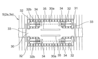
タイバー30は、ボイラ炉壁5の外表面に沿って水平方向に配置された板状部材であり、複数本の押さえピン33によってボイラ炉壁5の外表面に支持されている。前述したようにアンカープレート32とタイバー30は溶接されておらず、タイバー30には、アンカープレート32の溝部32aに嵌め込まれる一対の突出片30aが上下方向に向けて突出形成されている。溝部32aと突出片30aとは数ミリ程度の間隙を存して凹凸係合されており、突出片30aを溝部32aに嵌め込んだ後、両者の接合部分に跨るように4箇所に配置した各ストッパ部材34をアンカープレート32に溶接固定することにより、タイバー30がアンカープレート32から脱落しないようになっている。そして、タイバー30の外表面にスタンドオフ35が固定されており、このスタンドオフ35にバックステー20が当接している(図8参照)。
The
なお、ストッパ部材34はアンカープレート32と突出片30aのうち、少なくともアンカープレート32に溶接固定されていれば良く、例えば、全てのストッパ部材34をアンカープレート32と突出片30aに溶接固定しても良い。また、本実施形態では、一対のアンカープレート32を上下に配置しているので、上側2箇所のストッパ部材34をアンカープレート32に溶接固定して、下側2箇所のストッパ部材34を突出片30aに溶接固定するようにしても良い。
Note that the
このように構成されたボイラ装置では、タイバー30に設定されたアンカー部に突出片30aを形成し、この突出片30aとボイラ炉壁5のフィラプレート31に溶接固定したアンカープレート32の溝部32aとを凹凸係合することにより、タイバー30の基準点を中心としたボイラ炉壁5とバックステー20の伸び差を吸収するようにしている。その際、ボイラ炉壁5側に溶接固定されたアンカープレート32の熱伸縮は、アンカープレート32の溝部32aとタイバー30の突出片30aとの間に存する間隙によって吸収されるため、アンカープレート32のボイラ炉壁5に対する温度追従性が向上し、アンカープレート32の溶接部分に割れが発生することを抑制できる。しかも、タイバー30を挟んだ上下2位置にアンカープレート32を配置し、これらアンカープレート32の全周をボイラ炉壁5のフィラプレート31に溶接固定しているため、アンカープレート32を小型化してもタイバー30のアンカー部に必要とされる強度を確保することができる。
In the boiler device configured in this way, a protruding
そして、ボイラ炉壁5は、タイバー30に連結されたバックステー20を介して鉄骨柱12で支持されているため、地震発生時に作用する水平方向の振動は、バックステー20と鉄骨柱12との間に介在するサイスミックタイ13によって緩和される。なお、地震発生時におけるボイラ本体1の変位量は通常時に比べて大きいものとなり、アンカープレート32は溝部32aと突出片30aとの間の間隙を遥かに超えた移動量で変位するため、アンカープレート32とタイバー30は一体的に振動する。
Since the
以上説明したように、本実施形態に係るボイラ装置は、水管7で構成されたボイラ炉壁5を有するボイラ本体1と、ボイラ本体1の周囲に設けられた鉄骨柱12と、ボイラ本体1を包囲して水平方向に延在するバックステー20と、バックステー20をボイラ炉壁5に支持させるタイバー30とを備え、鉄骨柱12とバックステー20とがサイスミックタイ13を介して連結されているため、地震発生時にボイラ本体1の損傷を低減することができる。そして、タイバー30に設定されるアンカー部をタイバー30から分離して、アンカー部としてのアンカープレート32をボイラ炉壁5に溶接固定し、タイバー30に形成した突出片30aをアンカープレート32に形成した溝部32aに対して間隙を存して凹凸係合させると共に、ストッパ部材34によって突出片30aが溝部32aから脱落しないように構成したので、タイバー30をボイラ炉壁5に溶接する必要がなくなり、タイバー30の固定箇所に発生する溶接割れを抑制することができる。
As explained above, the boiler apparatus according to the present embodiment includes a boiler
しかも、タイバー30を挟んだ上下2位置にアンカープレート32を配置し、これらアンカープレート32の全周をボイラ炉壁5に溶接固定しているため、アンカープレート32の小型化が図れて熱応力を軽減することができ、タイバー30のアンカー部に必要とされる強度も確保することができる。
Moreover, because the
また、本実施形態に係るボイラ炉壁5の補強構造では、タイバー30に設定された伸び基準点となるアンカー部(アンカープレート32)をタイバー30から分離し、アンカープレート32をボイラ炉壁5に溶接固定すると共に、タイバー30に形成した突出片30aをアンカープレート32に形成した溝部32aに対して間隙を存して凹凸係合させ、ストッパ部材34によって突出片30aが溝部32aから脱落しないように構成したので、タイバー30をボイラ炉壁5に溶接する必要がなくなり、タイバー30の固定箇所に発生する溶接割れを抑制することができる。
In addition, in the reinforcement structure of the
なお、本発明は上記した実施形態に限定されるものではなく、様々な変形例が含まれる。上記した実施形態は本発明を分かりやすく説明するために詳細に説明したものであり、必ずしも説明した全ての構成を備えるものに限定されるものではない。 Note that the present invention is not limited to the embodiments described above, and includes various modifications. The embodiments described above have been described in detail to explain the present invention in an easy-to-understand manner, and are not necessarily limited to those having all the configurations described.
1 ボイラ本体
2a 水壁
3 ケージ部
3a ケージ壁
4 副側壁
5 ボイラ炉壁(炉壁)
7 水管
8 メンブレンバー
10 吊ロッド
11 鉄骨梁
12 鉄骨柱
13 サイスミックタイ
20 バックステー
30 タイバー
30a 突出片
31 フィラプレート
32 アンカープレート
32a 溝部
32b スリット
33 押さえピン
34 ストッパ部材
35 スタンドオフ1
7
Claims (4)
前記炉壁に溶接固定されるアンカープレートと、
前記バックステーに支持されると共に、前記アンカープレートに対して間隙を存して凹凸係合されるタイバーと、
前記タイバーの前記アンカープレートからの脱落を防止するストッパ部材と、
を備え、
前記アンカープレートは複数設けられ、
前記複数のアンカープレートが、前記タイバーを挟んだ上下2位置で前記炉壁に溶接固定され、
前記タイバーに上下方向に突出する一対の突出片が形成されており、これら突出片が前記複数のアンカープレートに形成された溝部と凹凸係合していることを特徴とするボイラ装置。 A boiler device comprising a boiler body having a furnace wall made up of water tubes, and a backstay surrounding the boiler body,
an anchor plate welded and fixed to the furnace wall;
a tie bar supported by the backstay and engaged with the anchor plate with a gap therebetween;
a stopper member that prevents the tie bar from falling off the anchor plate;
Equipped with
A plurality of the anchor plates are provided,
The plurality of anchor plates are welded and fixed to the furnace wall at two upper and lower positions sandwiching the tie bar,
A boiler device characterized in that a pair of protruding pieces that protrude in the vertical direction are formed on the tie bar, and these protruding pieces engage grooves formed in the plurality of anchor plates in a concave and convex manner.
前記ストッパ部材は、前記アンカープレートと前記タイバーとのうち少なくとも前記アンカープレートに溶接固定されていることを特徴とするボイラ装置。 The boiler device according to claim 1,
The boiler apparatus is characterized in that the stopper member is welded and fixed to at least the anchor plate of the anchor plate and the tie bar.
前記複数のアンカープレートのそれぞれにスリットが形成されていることを特徴とするボイラ装置。 The boiler device according to claim 1 or 2,
A boiler device characterized in that a slit is formed in each of the plurality of anchor plates.
前記ボイラ炉壁に溶接固定されるアンカープレートと、
前記ボイラ炉壁を包囲するバックステーに支持されると共に、前記アンカープレートに対して間隙を存して凹凸係合されるタイバーと、
前記タイバーの前記アンカープレートからの脱落を防止するストッパ部材と、
を備え、
前記アンカープレートは複数設けられ、
前記複数のアンカープレートが、前記タイバーを挟んだ上下2位置で前記ボイラ炉壁に溶接固定され、
前記タイバーに上下方向に突出する一対の突出片が形成されており、これら突出片が前記複数のアンカープレートに形成された溝部と凹凸係合していることを特徴とするボイラ炉壁の補強構造。 A reinforcement structure for a boiler furnace wall composed of water pipes,
an anchor plate welded and fixed to the boiler furnace wall;
a tie bar that is supported by a backstay that surrounds the boiler furnace wall and that is engaged with the anchor plate with a gap therebetween;
a stopper member that prevents the tie bar from falling off the anchor plate;
Equipped with
A plurality of the anchor plates are provided,
The plurality of anchor plates are welded and fixed to the boiler furnace wall at two upper and lower positions sandwiching the tie bar,
A reinforcing structure for a boiler furnace wall, characterized in that the tie bar is formed with a pair of protruding pieces that protrude in the vertical direction, and these protruding pieces are engaged with grooves formed in the plurality of anchor plates. .
Applications Claiming Priority (3)
| Application Number | Priority Date | Filing Date | Title |
|---|---|---|---|
| JP2020054586 | 2020-03-25 | ||
| JP2020054586 | 2020-03-25 | ||
| PCT/JP2020/047725 WO2021192461A1 (en) | 2020-03-25 | 2020-12-21 | Boiler device, and reinforcement structure of boiler furnace wall |
Publications (2)
| Publication Number | Publication Date |
|---|---|
| JPWO2021192461A1 JPWO2021192461A1 (en) | 2021-09-30 |
| JP7353463B2 true JP7353463B2 (en) | 2023-09-29 |
Family
ID=77891234
Family Applications (1)
| Application Number | Title | Priority Date | Filing Date |
|---|---|---|---|
| JP2022509271A Active JP7353463B2 (en) | 2020-03-25 | 2020-12-21 | Boiler equipment and boiler furnace wall reinforcement structure |
Country Status (2)
| Country | Link |
|---|---|
| JP (1) | JP7353463B2 (en) |
| WO (1) | WO2021192461A1 (en) |
Citations (1)
| Publication number | Priority date | Publication date | Assignee | Title |
|---|---|---|---|---|
| KR101613814B1 (en) | 2015-01-29 | 2016-04-19 | 문인득 | Method for replacing the steam generator of pressurized water reactor of 2 loop type |
Family Cites Families (6)
| Publication number | Priority date | Publication date | Assignee | Title |
|---|---|---|---|---|
| JPS5819938B2 (en) * | 1975-09-22 | 1983-04-20 | バブコツク日立株式会社 | Lohekigaisouzaino Shijisouchi |
| JPS53118601A (en) * | 1977-03-24 | 1978-10-17 | Babcock Hitachi Kk | Supporting device |
| JPS5771902U (en) * | 1980-10-14 | 1982-05-01 | ||
| JPH01291002A (en) * | 1988-05-16 | 1989-11-22 | Babcock Hitachi Kk | Structure to support water wall tube of boiler |
| US5207184A (en) * | 1992-04-03 | 1993-05-04 | The Babcock & Wilcox Company | Boiler buckstay system for membranded tube wall end connection |
| US5557901A (en) * | 1994-11-15 | 1996-09-24 | The Babcock & Wilcox Company | Boiler buckstay system |
-
2020
- 2020-12-21 JP JP2022509271A patent/JP7353463B2/en active Active
- 2020-12-21 WO PCT/JP2020/047725 patent/WO2021192461A1/en active Application Filing
Patent Citations (1)
| Publication number | Priority date | Publication date | Assignee | Title |
|---|---|---|---|---|
| KR101613814B1 (en) | 2015-01-29 | 2016-04-19 | 문인득 | Method for replacing the steam generator of pressurized water reactor of 2 loop type |
Also Published As
| Publication number | Publication date |
|---|---|
| WO2021192461A1 (en) | 2021-09-30 |
| JPWO2021192461A1 (en) | 2021-09-30 |
Similar Documents
| Publication | Publication Date | Title |
|---|---|---|
| US3203376A (en) | Buckstay arrangement for furnace walls | |
| CA2630201C (en) | Link type seismic tie for boilers | |
| US3814063A (en) | Support of tube walls | |
| JP7353463B2 (en) | Boiler equipment and boiler furnace wall reinforcement structure | |
| US4499860A (en) | Furnace buckstay design | |
| TWI744815B (en) | Boiler plant | |
| JP6888970B2 (en) | Construction method of joint structure between column and beam and joint structure between column and beam | |
| KR20110132314A (en) | Buckstay system | |
| KR102012499B1 (en) | Boiler Spiral Wall Supporting Structure For Thermal Power Plants | |
| WO2018230014A1 (en) | Elastic-plastic element, seismic tie comprising same, and boiler support structure | |
| TWI263232B (en) | Fuel-element for a pressure-water core-reactor | |
| JP5603741B2 (en) | Buckling restraint brace | |
| JP6142518B2 (en) | Support structure of exhaust heat recovery boiler | |
| JP5751862B2 (en) | Steel plate concrete structure design system and steel plate concrete structure design method | |
| JPH08296807A (en) | Support device for vertical flow type boiler | |
| JP2012097816A (en) | Elasto-plastic brace vibration isolation structure | |
| JP7242624B2 (en) | Elasto-plastic element, seismic tie with the same, and boiler support structure | |
| JP2753176B2 (en) | Heat transfer tube panel | |
| JP2013108662A (en) | Steam generator | |
| JP2004003697A (en) | Device for supporting horizontal element | |
| JP3774301B2 (en) | boiler | |
| JP3810856B2 (en) | Boiler equipment | |
| JP2017101860A (en) | Denitrification reactor | |
| JP2023036339A (en) | Seismic reinforcement device for support structure | |
| JP6632471B2 (en) | Segment joint structure |
Legal Events
| Date | Code | Title | Description |
|---|---|---|---|
| A621 | Written request for application examination |
Free format text: JAPANESE INTERMEDIATE CODE: A621 Effective date: 20220825 |
|
| AA64 | Notification of invalidation of claim of internal priority (with term) |
Free format text: JAPANESE INTERMEDIATE CODE: A241764 Effective date: 20221018 |
|
| A521 | Request for written amendment filed |
Free format text: JAPANESE INTERMEDIATE CODE: A523 Effective date: 20221031 |
|
| A131 | Notification of reasons for refusal |
Free format text: JAPANESE INTERMEDIATE CODE: A131 Effective date: 20230606 |
|
| A521 | Request for written amendment filed |
Free format text: JAPANESE INTERMEDIATE CODE: A523 Effective date: 20230714 |
|
| TRDD | Decision of grant or rejection written | ||
| A01 | Written decision to grant a patent or to grant a registration (utility model) |
Free format text: JAPANESE INTERMEDIATE CODE: A01 Effective date: 20230829 |
|
| A61 | First payment of annual fees (during grant procedure) |
Free format text: JAPANESE INTERMEDIATE CODE: A61 Effective date: 20230919 |
|
| R150 | Certificate of patent or registration of utility model |
Ref document number: 7353463 Country of ref document: JP Free format text: JAPANESE INTERMEDIATE CODE: R150 |