JP7350250B2 - gaming machine - Google Patents
gaming machine Download PDFInfo
- Publication number
- JP7350250B2 JP7350250B2 JP2019024994A JP2019024994A JP7350250B2 JP 7350250 B2 JP7350250 B2 JP 7350250B2 JP 2019024994 A JP2019024994 A JP 2019024994A JP 2019024994 A JP2019024994 A JP 2019024994A JP 7350250 B2 JP7350250 B2 JP 7350250B2
- Authority
- JP
- Japan
- Prior art keywords
- special
- game
- jackpot
- control device
- setting
- Prior art date
- Legal status (The legal status is an assumption and is not a legal conclusion. Google has not performed a legal analysis and makes no representation as to the accuracy of the status listed.)
- Active
Links
Images


Description
本発明は、遊技機に関する。 The present invention relates to a gaming machine.
従来、遊技に関する設定に応じた設定値を変更可能な遊技機が存在している(例えば、特許文献1)。 2. Description of the Related Art Conventionally, there has been a gaming machine that can change setting values according to settings related to a game (for example, Patent Document 1).
しかしながら、従来の遊技機において、不正が行われた際の対策には向上の余地があった。 However, in conventional gaming machines, there is room for improvement in countermeasures against fraud.
そこで、本発明は、遊技機に対する不正を報知することを目的とする。 Therefore, it is an object of the present invention to notify fraudsters against gaming machines .
本発明の代表的な一形態では、ゲームを実行し、遊技者に有利な特別遊技状態および特定遊技状態を発生可能な制御手段を備える遊技機において、前記ゲームに関する情報が記憶され、停電が発生しても記憶された情報を保持することが可能な記憶手段を備え、前記記憶手段は、記憶された情報の正当性判定の対象となる記憶領域と、記憶された情報の正当性判定の対象とならない記憶領域とを含み、前記制御手段は、前記特別遊技状態の発生を契機に信号を出力開始し、当該特別遊技状態後の前記特定遊技状態が終了するまで当該信号を出力可能であり、当該遊技機に発生する可能性のある複数の事象に対応して、事象の発生を報知するセキュリティ信号を出力可能であり、前記特別遊技状態中または前記特定遊技状態中に停電し、復電された際に前記正当性判定の対象とならない記憶領域に記憶された情報の正当性判定を行わずに前記正当性判定の対象となる記憶領域に記憶された情報の正当性判定を行い、当該正当性判定の結果が異常となった場合は、当該異常を報知するための前記セキュリティ信号を出力し、前記信号を出力しない。 In a typical form of the present invention, in a gaming machine equipped with a control means capable of executing a game and generating a special gaming state and a specific gaming state advantageous to a player, information regarding the game is stored, and when a power outage occurs The storage means includes a storage area that is the target of the validity determination of the stored information, and a storage area that is the target of the validity determination of the stored information. and a storage area in which the control means starts outputting a signal upon the occurrence of the special gaming state, and is capable of outputting the signal until the specific gaming state after the special gaming state ends; In response to multiple events that may occur in the gaming machine, it is possible to output a security signal to notify the occurrence of the event , and even if the power is cut off during the special gaming state or the specific gaming state, the power is restored. When the validity determination is made, the validity of the information stored in the storage area that is the target of the validity determination is determined without performing the validity determination of the information stored in the storage area that is not the target of the validity determination, and the If the result of the validity determination is abnormal, the security signal for notifying the abnormality is output, and the signal is not output.
本発明の一形態によれば、遊技機に対する不正を報知することができる。 According to one embodiment of the present invention, it is possible to notify of fraud against a gaming machine .
[第1実施形態]
以下、本発明の好適な実施の形態を図面に基づいて説明する。なお、遊技機の説明にお
ける前後左右とは、遊技中の遊技者から見た方向を指すものとする。
[First embodiment]
Hereinafter, preferred embodiments of the present invention will be described based on the drawings. Note that in the description of the gaming machine, front, rear, left, and right refer to the directions seen from the player during the game.
〔遊技機全体図〕
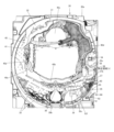
図1は、遊技機を説明する図である。
[Overview of gaming machine]
FIG. 1 is a diagram illustrating a gaming machine.
遊技機10は島設備に固定される枠11に、ヒンジを介して開閉回動自在に取り付けら
れる開閉枠を備える。開閉枠は、前面枠12(本体枠)及びガラス枠15によって構成さ
れている。
The
前面枠12には、遊技盤30(図2参照)が配設されるとともに、遊技盤30の前面を
覆うカバーガラス14を有するガラス枠15が取り付けられる。カバーガラス14は、遊
技盤30に形成される遊技領域32(図2参照)を視認可能とする遊技視認領域として機
能する。
A game board 30 (see FIG. 2) is disposed on the
前面枠12及びガラス枠15は、それぞれ個別に開放することが可能となっている。例
えば、ガラス枠15のみを開放することで、遊技盤30の遊技領域32にアクセスするこ
とができる。また、前面枠12をガラス枠15が開放されていない状態で開放することで
、遊技盤30の裏面側に配設された遊技制御装置(主基板)100(図3参照)等にアク
セスすることができる。
The
ガラス枠15のカバーガラス14周囲の縁部分には、種々の枠構成部材が配設されてい
る。
Various frame constituent members are arranged at the edge portion of the glass frame 15 around the cover glass 14.
ガラス枠15の上部中央及び左側部には、遊技状態に応じて発光演出可能な装飾装置1
8a,18bが配設されている。装飾装置18a,18bは、内部にLED等の照明部材
を収容しており、遊技状態に応じた発光演出を行う。これら装飾装置18a,18bの内
部に配設される照明部材は、枠装飾装置18(図4参照)の一部を構成している。
At the upper center and left side of the glass frame 15, there is a
8a and 18b are provided. The decoration devices 18a and 18b house lighting members such as LEDs inside, and perform a light emitting effect according to the game state. The lighting members arranged inside these decoration devices 18a and 18b constitute a part of the frame decoration device 18 (see FIG. 4).
ガラス枠15の上右角部分及び上左角部分には、上スピーカ19aがそれぞれ配設され
る。これら上スピーカ19aとは別に遊技機10の下部には、2つの下スピーカ19bが
設けられている。下スピーカ19bは、ガラス枠15の下左角部分及び前面枠12の下右
角部分に配設されている。これら上スピーカ19a及び下スピーカ19bは、効果音や警
報音、報知音等を発するものである。
ガラス枠15の右側部には、遊技機10の上下方向に延設されるとともに、前方(遊技
者側)に向かって突出する突出演出ユニット13が配設されている。突出演出ユニット1
3は、遊技の進行状態に応じて発光演出等を行う演出装置である。突出演出ユニット13
の内部に配設される照明部材も枠装飾装置18(図4参照)の一部を構成している。
On the right side of the glass frame 15, a
The lighting member disposed inside the frame decoration device 18 (see FIG. 4) also constitutes a part of the frame decoration device 18 (see FIG. 4).
ガラス枠15の下部には、遊技球を貯留可能な上皿21を有する上皿ユニットが取り付
けられている。上皿21は、上面が開口した箱状に形成されている。上皿21に貯留され
ている遊技球は、一球ずつ球発射装置(図示省略)に供給される。
An upper tray unit having an upper tray 21 capable of storing game balls is attached to the lower part of the glass frame 15. The upper plate 21 is formed into a box shape with an open top. The game balls stored in the upper tray 21 are supplied one by one to a ball firing device (not shown).
上皿ユニットは、遊技者からの入力操作を受け付ける演出操作装置と、遊技者からの入
力操作を受け付ける球貸操作装置と、遊技状態に応じて発光演出等を行う装飾装置22と
、をさらに備える。
The upper tray unit further includes a production operation device that accepts input operations from players, a ball rental operation device that accepts input operations from players, and a decoration device 22 that performs light emission production etc. according to the game state. .
演出操作装置は、演出ボタン25にタッチパネル25bを組み込んだ操作装置であり、
遊技者が操作しやすいように上皿ユニットの上部中央に設けられている。
The production operation device is an operation device in which a
It is provided in the upper center of the upper tray unit for easy operation by the player.
遊技者が演出操作装置を操作することによって、表示装置41(図2参照)に表示され
る特図変動表示ゲーム等において遊技者の操作を介入させた演出を行うことができる。例
えば、演出パターン(演出態様)を選択したり、始動記憶に対応する変動表示ゲームの結
果を事前に予告する予告演出を実行したりすることができる。なお、変動表示ゲームには
特図変動表示ゲームが含まれ、単に変動表示ゲームとした場合には、本明細書では特図変
動表示ゲームを指すものとする。
By the player operating the performance operation device, it is possible to perform a performance in which the player's operation intervenes in a special figure fluctuation display game or the like displayed on the display device 41 (see FIG. 2). For example, it is possible to select a performance pattern (performance mode), or to execute a preview performance that foretells in advance the result of the variable display game corresponding to the starting memory. Incidentally, the variable display game includes a special figure variable display game, and when simply referred to as a variable display game, this specification refers to a special figure variable display game.
また、変動表示ゲームの実行中だけでなく、非実行中に遊技者が演出操作装置を操作す
ることによっても演出パターンを変更するようにしてもよい。
Furthermore, the effect pattern may be changed not only while the variable display game is being executed, but also by the player operating the effect operation device while the variable display game is not being executed.
なお、変動表示ゲームが実行される際の遊技状態は、複数の遊技状態からなる。通常遊
技状態(通常状態)とは、特別な遊技状態が発生していない遊技状態である。また、特別
な遊技状態とは、例えば、特定遊技状態としての時短状態や変動表示ゲームにおいて特別
結果(例えば大当り)の発生確率が高い状態(確変状態、確率変動状態)、大当り状態(
特別遊技状態)、小当り遊技状態(小当り状態)である。
Note that the game state when the variable display game is executed consists of a plurality of game states. The normal gaming state (normal state) is a gaming state in which no special gaming state occurs. In addition, special gaming states include, for example, a time saving state as a specific gaming state, a state where the probability of a special result (e.g. jackpot) is high in a variable display game (variable probability state, variable probability state), jackpot state (
A special game state) and a small win game state (a small win state).
ここで、確変状態(特定遊技状態)は、次の大当りが発生するまで継続するもの(ルー
プタイプ)、所定回数の変動表示ゲームが実行されるまで継続するもの(回数切りタイプ
、ST)、及び所定の確率転落抽選に当選するまで継続するもの(転落抽選タイプ)等が
ある。
Here, the variable probability states (specific gaming states) include those that continue until the next jackpot occurs (loop type), those that continue until a predetermined number of variable display games are executed (number-of-time type, ST), and There is a type of lottery that continues until you win a lottery with a predetermined probability (fall lottery type).
さらに、確変状態を発生させるか否かを大当り図柄乱数によって決定せずに、大当りが
発生した場合に必ず確変状態を発生させるようにしてもよいし、特定領域を備える入賞装
置等を設け、特定領域を遊技球が通過した場合に確変状態を発生させるようにしてもよい
。
Furthermore, whether or not to generate a variable probability state may be determined by random numbers of jackpot symbols, and the variable probability state may always be generated when a jackpot occurs, or a winning device with a specific area may be provided to specify A variable probability state may be generated when a game ball passes through the area.
球貸操作装置は、遊技者が遊技球を借りる場合に操作する操作装置であって、上皿ユニ
ットの上部右側に設けられている。球貸操作装置は、球貸ボタン27と、返却ボタン28
と、残高表示部26と、を備えている。球貸ボタン27は遊技球を借りる場合に遊技者が
操作するボタンであり、返却ボタン28は遊技機10に隣接するように配置されるカード
ユニット(図示省略)からプリペイドカード等を排出させる場合に遊技者が操作するボタ
ンである。残高表示部26は、プリペイドカード等の残高が表示される表示領域である。
The ball rental operation device is an operation device operated by a player when borrowing game balls, and is provided on the upper right side of the upper tray unit. The ball rental operation device has a ball rental button 27 and a
and a balance display section 26. The ball rental button 27 is a button operated by the player when borrowing game balls, and the
装飾装置22は、内部にLED等の照明部材を収容しており、遊技状態に応じて発光演
出等を行う装置であって、上皿ユニットの前側部分に設けられている。装飾装置22の内
部に配設される照明部材は、枠装飾装置18(図4参照)の一部を構成している。
The decoration device 22 houses lighting members such as LEDs inside, and is a device that performs lighting effects depending on the game state, and is provided in the front portion of the upper tray unit. The lighting member disposed inside the decoration device 22 constitutes a part of the frame decoration device 18 (see FIG. 4).
上記した上皿ユニット等を備えるガラス枠15の下方であって、前面枠12の下部には
、球発射装置(図示省略)の動作を制御するための操作ハンドル24と、遊技球を貯留可
能な下皿23とが設けられている。
Below the glass frame 15 including the above-mentioned upper plate unit, etc., and at the bottom of the
操作ハンドル24は、前面枠12の右下部であって、右側の下スピーカ19bの下方に
配置されている。遊技者が操作ハンドル24を回動操作することによって、球発射装置は
上皿21から供給された遊技球を遊技盤30の遊技領域32に発射する。球発射装置から
発射される遊技球の発射速度は、操作ハンドル24の回動操作量が大きくなるほど速くな
るように設定されている。即ち、球発射装置は、遊技領域に遊技球を発射する勢(速度)
である発射勢を、遊技者による操作ハンドル24の操作に対応して変更でき、発射勢の異
なる種々の発射態様で遊技球を発射できる。発射態様には、遊技領域32の左側において
遊技球を流下させる左打ち(通常打ち)と、遊技領域32の右側において遊技球を流下さ
せる右打ちが含まれる。
The operation handle 24 is located at the lower right portion of the
The firing force can be changed in accordance with the operation of the operating handle 24 by the player, and the game ball can be fired in various firing modes with different firing forces. The firing mode includes left-handed hitting (normal hitting) in which the game ball flows down on the left side of the
下皿23は、上皿ユニットに対して所定の間隔をあけて、上皿ユニットの下方に配置さ
れている。下皿23は、当該下皿23の底面を上下方向に貫通する球抜き穴23aと、球
抜き穴23aを開閉するための開閉操作部23bと、を有している。遊技者が開閉操作部
23bを操作して、球抜き穴23aを開くことによって、下皿23に貯留されていた遊技
球を球抜き穴23aを通じて外部に排出することができる。
The lower plate 23 is arranged below the upper plate unit at a predetermined distance from the upper plate unit. The lower plate 23 has a ball hole 23a that vertically passes through the bottom surface of the lower plate 23, and an opening/closing operation part 23b for opening and closing the ball hole 23a. When the player operates the opening/closing operation part 23b to open the ball removal hole 23a, the game balls stored in the lower tray 23 can be discharged to the outside through the ball removal hole 23a.
〔遊技盤〕
続いて、図2を参照して、遊技機10の遊技盤30について説明する。図2は、遊技機
10に備えられる遊技盤30の正面図である。
[Game board]
Next, with reference to FIG. 2, the
図2に示すように、遊技盤30は、各種部材の取付ベースとなる平板状の遊技盤本体3
0aを備える。遊技盤本体30aは木製又は合成樹脂製であって、当該遊技盤本体30a
の前面にはガイドレール31で囲まれた遊技領域32が設けられている。遊技機10は、
ガイドレール31で囲まれた遊技領域32内に球発射装置から遊技球を発射して遊技を行
うように構成されている。遊技領域32には遊技球の流下方向を変換する部材として風車
や障害釘等が配設されており、発射された遊技球はこれら部材により転動方向を変えなが
ら遊技領域32を流下する。
As shown in FIG. 2, the
Equipped with 0a. The game board
A
It is configured to play a game by firing a game ball from a ball firing device into a
遊技領域32の略中央には、変動表示ゲームの表示領域となる窓部を形成するセンター
ケース(前面構成体)40が取り付けられている。センターケース40に形成された窓部
の後方には、複数の識別情報を変動表示(可変表示)する演出表示装置(変動表示装置)
としての表示装置41が配置されている。表示装置41は、例えば、液晶ディスプレイを
備え、センターケース40の窓部を介して遊技盤30の前面側から表示内容が視認可能と
なるように配置される。なお、表示装置41は、液晶ディスプレイを備えるものに限らず
、ELやCRT等のディスプレイを備えるものであってもよい。
At approximately the center of the
A
表示装置41の表示画面(表示部)には、複数の変動表示領域が設けられており、各変
動表示領域に識別情報(特別図柄)や変動表示ゲームを演出するキャラクタが表示される
。その他、表示画面には遊技の進行に基づく画像(大当り表示やファンファーレ表示、エ
ンディング表示等)が表示される。
The display screen (display unit) of the
また、センターケース40には、遊技領域32を流下する遊技球をセンターケース40
の内側に導くためのワープ通路40eへの流入口40aと、ワープ通路40eを通過した
遊技球が転動可能なステージ部40bとが設けられている。センターケース40のステー
ジ部40bは、始動入賞口36及び普通変動入賞装置37の上方に配置されているため、
ステージ部40b上で転動した遊技球は始動入賞口36又は普通変動入賞装置37に入賞
しやすくなっている。
In addition, the
An
The game ball rolling on the
センターケース40の上部及び右側部には、それぞれ上部演出ユニット40c及び側部
演出ユニット40dが設けられる。上部演出ユニット40c及び側部演出ユニット40d
は、盤装飾装置46(図4参照)及び盤演出装置44(図4参照)の一部を構成している
。
An
constitutes a part of the board decoration device 46 (see FIG. 4) and the board presentation device 44 (see FIG. 4).
センターケース40の右側方の遊技領域32には、普通図柄始動ゲート(普図始動ゲー
ト)34が設けられている。普図始動ゲート34の内部には、当該普図始動ゲート34を
通過した遊技球を検出するためのゲートスイッチ(SW)34a(図3参照)が設けられ
ている。遊技領域32内に打ち込まれた遊技球が普図始動ゲート34を通過すると、普図
変動表示ゲームが実行される。
In the
センターケース40の左下方の遊技領域32には一般入賞口35が配置されており、セ
ンターケース40の右下方の遊技領域32にも一般入賞口35が配置されている。これら
一般入賞口35への遊技球の入賞は、一般入賞口35に備えられた入賞口スイッチ(SW
)35a~35n(図3参照)によって検出される。
A general winning
) 35a to 35n (see FIG. 3).
センターケース40の下方の遊技領域32には、特図変動表示ゲームの開始条件を付与
する始動入賞口(始動口1、第1始動入賞領域)36が設けられる。センターケース40
の右側の遊技領域32において、普図始動ゲート34の下方には第2始動入賞口(始動口
2、第2始動入賞領域)を備えた普通変動入賞装置37(普通電動役物、普電)が設けら
れる。普通変動入賞装置37は、前方から奥側に引っ込むようにスライドすることで、遊
技球が流入し易い状態に変換する可動部材(可動片)37bを備える。可動部材37bが
閉状態である場合には遊技球が普通変動入賞装置37に入賞できないようになっている。
遊技球が始動入賞口36又は普通変動入賞装置37に入賞した場合には、補助遊技として
特図変動表示ゲームが実行される。なお、始動入賞口36には、左打ち時に遊技球が入賞
し易くなり、普通変動入賞装置37には、右打ち時に遊技球が入賞し易くなる。
In the
In the
When the game ball wins in the
可動部材37bは、スライド開閉式の普通電動役物であり、普図変動表示ゲームの結果
が所定の停止表示態様となった場合に、普電ソレノイド37c(図3参照)を介して動作
して開いて、遊技球が普通変動入賞装置37に流入しやすい開状態(遊技者にとって有利
な入賞容易状態)に変化する。
The
なお、可動部材37bは、後述する遊技制御装置100によって制御される。遊技制御
装置100は、普図変動表示ゲームの変動時間を短縮したり普図変動表示ゲームの当り確
率を通常よりも高確率としたりすることで入賞容易状態の発生頻度を高めたり、通常遊技
状態で発生する入賞容易状態よりも入賞容易状態の発生時間を長くしたりすることで、前
述の特定遊技状態として時短状態(普電サポート状態)を発生させる。なお、確変状態(
潜伏確変状態を除く)においても、重複して時短状態(普電サポート状態)が発生する。
In addition, the
(excluding the latent and probable variable state), the time-saving state (general power support state) occurs overlappingly.
始動入賞口36の右方の遊技領域32には、下大入賞口ソレノイド38b(図7参照)
によって前方から奥側に引っ込むことで大入賞口を開放する下大入賞口を開放するアタッ
カ形式の開閉扉38cを有する第1特別変動入賞装置38(特別電動役物)が設けられて
いる。第1特別変動入賞装置38は、特図変動表示ゲームの結果によって大入賞口を閉じ
た状態(遊技者にとって不利な閉塞状態)から開放状態(遊技者にとって有利な遊技状態
)に変換し、下大入賞口内への遊技球の流入を容易にさせることで、遊技者に所定の遊技
価値(賞球)を付与するようになっている。なお、下大入賞口内には、当該大入賞口に入
った遊技球を検出する検出手段として下大入賞口スイッチ38a(カウントスイッチ)が
配設されている。なお、第1特別変動入賞装置38には、右打ち時に遊技球が入賞し易く
なる。
In the
A first special variable winning device 38 (special electric accessory) is provided which has an attacker-type opening/
普通変動入賞装置37の上方の遊技領域32には、上大入賞口ソレノイド39b(図3
参照)によって上端側が右側に倒れる方向に回動することで上大入賞口を開放する開閉扉
39cを有する第2特別変動入賞装置39が設けられている。第2特別変動入賞装置39
は、特図変動表示ゲームの結果によって大入賞口を閉じた状態(遊技者にとって不利な閉
塞状態)から開放状態(遊技者にとって有利な特別遊技状態)に変換し、大入賞口内への
遊技球の流入を容易にさせることで、遊技者に所定の遊技価値(賞球)を付与するように
なっている。なお、大入賞口内には、当該大入賞口に入った遊技球を検出する検出手段と
して上大入賞口スイッチ39a(カウントスイッチ)(図3参照)が配設されている。な
お、第2特別変動入賞装置39には、右打ち時に遊技球が入賞し易くなる。また、下大入
賞口スイッチ38aと上大入賞口スイッチ39aを総称して、大入賞口スイッチ43と呼
ぶ。
In the
A second special variable
Converts the grand prize opening from a closed state (blocked state disadvantageous to the player) to an open state (special gaming state advantageous to the player) depending on the result of the special figure fluctuation display game, and allows the game ball to enter the grand prize opening. By facilitating the influx of players, a predetermined gaming value (prize ball) is given to the player. In addition, in the grand prize opening, an upper large winning a prize opening switch 39a (count switch) (see FIG. 3) is arranged as a detection means for detecting a game ball that has entered the said grand prize opening. It should be noted that the second special variable winning
第2特別変動入賞装置39の内部には、特定領域86(いわゆるV入賞口)が設けられ
ている。特定領域86(V入賞口)に遊技球が入球した場合に大当り終了後の確変状態(
高確率状態、特定遊技状態)が確定する。特定領域86は、確変大当りの場合にのみ、長
時間開放されるなどして遊技球が容易に通過できるようにしてよい。なお、遊技制御装置
100は、特定領域86への遊技球の通過(V入賞)をセンサ(後述の特定領域スイッチ
72)等を介して検知でき、V入賞を検知すると大当り終了後に確変状態に移行すること
を確定するとともに、後述の演出制御装置300にV入賞があったことを示す情報(特定
領域通過コマンド等)を送信する。そして、演出制御装置300は、V入賞を表示装置4
1などにおいて報知できる。
Inside the second special variable winning
High probability state, specific game state) is confirmed. The
1 etc. can be notified.
一般入賞口35、始動入賞口36、普通変動入賞装置37、及び特別変動入賞装置38
、39の大入賞口に遊技球が入賞すると、払出制御装置200(図3参照)は、入賞した
入賞口の種類に応じた数の賞球を払出装置から上皿21に排出する。また、下方の遊技領
域32には、入賞口等に入賞しなかった遊技球を回収するアウト口30bが設けられてい
る。また、一般入賞口35、始動入賞口36、普通変動入賞装置37、及び特別変動入賞
装置38、39やその近傍には、遊技球が入賞した場合などに発光可能なLED(後述の
盤装飾装置46の一部)が配設されている。
General winning
, 39, the payout control device 200 (see FIG. 3) discharges the number of prize balls from the payout device to the upper tray 21 according to the type of winning hole. Further, in the
また、遊技領域32の外側であって遊技盤本体30aの右下角部には、特図変動表示ゲ
ーム(特図1変動表示ゲーム、特図2変動表示ゲーム)及び普図変動表示ゲームを実行す
る一括表示装置50が設けられている。一括表示装置50は、現在の遊技状態等の情報を
表示する表示部51~60を備える。
In addition, outside the
一括表示装置50は、7セグメント型の表示器(LEDランプ)等で構成された変動表
示ゲーム用の第1特図変動表示部51(特図1表示器、ランプD1)及び第2特図変動表
示部52(特図2表示器、ランプD2)と、普図変動表示ゲーム用の変動表示部53(普
図表示器、ランプD8、D10、D18)と、各変動表示ゲームの始動(保留)記憶数報
知用の記憶表示部(特図1保留表示器54、特図2保留表示器55、普図保留表示器56
)と、を有している。特図1保留表示器54はランプD11、D12により構成される。
特図2保留表示器55は、ランプD13、D14により構成される。普図保留表示器56
は、ランプD15、D16により構成される。
The
) and has. The special figure 1 reservation display 54 is composed of lamps D11 and D12.
The special figure 2 reservation display 55 is composed of lamps D13 and D14. General
is composed of lamps D15 and D16.
また、一括表示装置50には、右打ち時(右打ちすべき時)又は左打ち時(通常打ち時
)であることを報知する第1遊技状態表示部57(第1遊技状態表示器、ランプD7)、
時短状態が発生すると点灯して時短状態発生を報知する第2遊技状態表示部58(第2遊
技状態表示器、ランプD17)、遊技機10の電源投入時に大当りの確率状態が高確率状
態となっていることを表示する第3遊技状態表示部59(第3遊技状態表示器、確率状態
表示部、ランプD9)、大当り時のラウンド数(特別変動入賞装置38、39の開閉回数
)を表示するラウンド表示部60(ランプD3-D6)が設けられている。
In addition, the
When the time saving state occurs, the second gaming state display section 58 (second gaming state indicator, lamp D17) lights up to notify the occurrence of the time saving state, and when the
特図1表示器51と特図2表示器52において、変動表示ゲームは、識別情報(例えば
、中央のセグメント)の点灯消灯(点滅)を繰り返す変動表示によって実行される。なお
、特図1表示器51、特図2表示器52は、このようなセグメント型の表示部に限らず、
複数のLEDの集合体により構成されていてもよいし、変動表示を実行する場合に、表示
器として設けられるすべてのLEDにより全点灯全消灯(全LEDの同時点滅)や、循環
点灯(何れか1のLEDから所定時間毎に所定の順序で点灯し、消灯する)、または複数
のLEDのうちの所定数のLEDによる点灯消灯(点滅)や循環点灯によって行ってもよ
い。普図表示器53においても、変動表示ゲームは、ランプD10、D18の点灯消灯を
繰り返す変動表示(点滅)によって実行される。また、普図表示器53も特図1表示器5
1、特図2表示器52と同様に適宜構成することが可能である。
In the special figure 1
It may be composed of an aggregate of multiple LEDs, and when performing a variable display, all LEDs provided as an indicator can be turned on or off (all LEDs blink at the same time), or cycled on (one of them). The light may be turned on and off in a predetermined order at predetermined intervals starting from one LED, or may be turned on and off (flashing) or cycled by a predetermined number of LEDs among a plurality of LEDs. Also on the
1. Like the special figure 2
ランプ表示装置80は、図柄(後述の第四特別図柄)として点灯表示と消灯表示を繰り
返す変動表示(点滅)を実行するランプ表示部1、2(LED)と、各特図変動表示ゲー
ムの始動(保留)記憶数報知用のランプ表示部3-6(LED)を有する。なお、ランプ
表示装置80は、演出制御装置300(後述)で制御される。
The
ランプ表示部1、2は、変動表示として所定の点滅周期(例えば200msec(ミリ
秒))で点滅する。一括表示装置50の特図1表示器51、特図2表示器52、普図表示
器53における変動表示の変動時間が遊技制御装置100で計測されるのに対して、ラン
プ表示装置80のランプ表示部1、2の変動時間は演出制御装置300(後述)で計測さ
れる。
The
ランプ表示部3、4(特図1保留LED1、特図1保留LED2)は、消灯状態、点灯
状態、点滅状態の組合せによって、特図1保留数(第1始動記憶数)を表示する。同様に
、ランプ表示部5、6(特図2保留LED1、特図2保留LED2)は、消灯状態、点灯
状態、点滅状態の組合せによって、特図2保留数(第2始動記憶数)を表示する。ランプ
表示部3-6は、大当り発生により保留数の表示を終了するが、大当り状態中以外の場合
(表示装置41で後述のリーチが発生している場合も含む)では、保留数の表示を行う。
The
次に、遊技機10における遊技の流れ、普図変動表示ゲーム及び特図変動表示ゲームの
詳細について説明する。
Next, details of the flow of the game in the
遊技機10では、図示しない球発射装置から遊技領域32に向けて遊技球が打ち出され
ることによって遊技が行われる。打ち出された遊技球は、遊技領域32内の各所に配置さ
れた障害釘や風車等によって転動方向を変えながら遊技領域32を流下し、普図始動ゲー
ト34、一般入賞口35、始動入賞口36、普通変動入賞装置37、又は特別変動入賞装
置38、39に入賞するか、遊技領域32の最下部に設けられたアウト口30bへ流入し
、遊技領域32から排出される。そして、一般入賞口35、始動入賞口36、普通変動入
賞装置37、又は特別変動入賞装置38、39に遊技球が入賞すると、入賞した入賞口の
種類に応じた数の賞球が払出装置を介して上皿21に排出される。
In the
普図始動ゲート34には、当該普図始動ゲート34を通過した遊技球を検出するゲート
スイッチ34a(図3参照)が設けられている。遊技球が普図始動ゲート34を通過する
と、ゲートスイッチ34aによって検出され、このときに抽出された当り判定用乱数値の
判定結果に基づき普図変動表示ゲームが実行される。
The regular
普図変動表示ゲームを開始できない状態、例えば、既に普図変動表示ゲームが行われて
おり当該普図変動表示ゲームが終了していない場合や、普図変動表示ゲームの結果が当り
となって普通変動入賞装置37が開放状態に変換されている場合に、遊技球が普図始動ゲ
ート34を通過すると、普図始動記憶数が上限数未満ならば当該記憶数が加算(+1)さ
れる。
Conditions in which the general pattern fluctuation display game cannot be started, for example, when the general pattern fluctuation display game is already being played and the relevant general pattern fluctuation display game has not finished, or when the result of the general pattern fluctuation display game is a win and it is normal. When the variable
普図始動記憶には普図変動表示ゲームの当りはずれを決定するための当り判定用乱数値
が記憶されており、この当り判定用乱数値が判定値と一致した場合に、当該普図変動表示
ゲームが当りとなって特定の結果態様(特定結果)が導出される。
The normal pattern starting memory stores a random number value for determining the hit or miss of the normal pattern fluctuation display game, and when this random number value for winning judgment matches the judgment value, the corresponding normal pattern fluctuation display is When the game is won, a specific result pattern (specific result) is derived.
普図変動表示ゲームは、一括表示装置50に設けられた普図表示器53で実行されるよ
うになっている。普図表示器53は、普通識別情報(普図)として点灯状態の場合に当り
を示し、消灯状態の場合にはずれを示すLEDから構成され、このLEDを点滅表示する
ことで普通識別情報の変動表示を行い、所定の変動表示時間の経過後、LEDを点灯又は
消灯することで結果を表示するようになっている。
The ordinary figure fluctuation display game is executed on the
普図始動ゲート34通過時に抽出された普図乱数値が当り値である場合には、普図表示
器53に表示される普通図柄が当り状態で停止し、当り状態となる。このとき、普電ソレ
ノイド37c(図3参照)が駆動されることにより、可動部材37bが所定の時間(例え
ば0.3秒間)だけ開状態に変換され、普通変動入賞装置37への遊技球の入賞が許容さ
れる。
When the normal pattern random number value extracted at the time of passing through the normal
遊技球の始動入賞口36への入賞及び普通変動入賞装置37への入賞は、始動口1スイ
ッチ36a(図3参照)及び始動口2スイッチ37a(図3参照)によって検出される。
始動入賞口36に入賞した遊技球は特図1変動表示ゲームの始動入賞球として検出され、
所定の上限数を限度に記憶されるとともに、普通変動入賞装置37に入賞した遊技球は特
図2変動表示ゲームの始動入賞球として検出され、所定の上限数を限度に記憶される。
The winning of the game ball into the
The game ball that won the
The winning balls are stored up to a predetermined upper limit number, and the game balls that win in the normal
特図変動表示ゲームの始動入賞球の検出時には、大当り乱数値や大当り図柄乱数値、各
変動パターン乱数値等が抽出される。これら乱数値は、遊技制御装置100の特図保留記
憶領域(RAMの一部)に特図始動入賞記憶として各々所定回数分(例えば最大で8回分
)を限度に記憶される。特図始動入賞記憶の記憶数は、一括表示装置50の始動入賞数報
知用の特図1保留表示器54や特図2保留表示器55に表示されるとともに、表示装置4
1の表示画面にも表示される。
At the time of detecting the starting prize ball of the special figure fluctuation display game, the jackpot random number, the jackpot symbol random number, each fluctuation pattern random number, etc. are extracted. These random numbers are stored in the special figure reservation storage area (part of the RAM) of the
It is also displayed on the display screen of 1.
遊技制御装置100は、始動入賞口36への入賞若しくは第1始動記憶に基づいて、特
図1表示器51で特図1変動表示ゲームを実行する。また、遊技制御装置100は、普通
変動入賞装置37への入賞若しくは第2始動記憶に基づいて、特図2表示器52で特図2
変動表示ゲームを実行する。
The
Run a variable display game.
特図1変動表示ゲーム(第1特図変動表示ゲーム)及び特図2変動表示ゲーム(第2特
図変動表示ゲーム)は、特図1表示器51及び特図2表示器52において識別情報(特別
図柄、特図)を変動表示した後に所定の結果態様を停止表示することで行われる。
In the special figure 1 variable display game (first special figure variable display game) and the special figure 2 variable display game (second special figure variable display game), identification information ( This is done by displaying a predetermined result mode in a fixed manner after variably displaying special symbols (special symbols, special symbols).
なお、本実施形態において、遊技機10は、いわゆる同時変動機であり、特図1変動表
示ゲーム及び特図2変動表示ゲームは互いに独立して、同時に(共に)実行状態にするこ
とができる。特図1変動表示ゲームで大当り(本実施形態で特図1変動表示ゲームに小当
りはない)が発生する場合には、実行中の特図2変動表示ゲームは、強制的にはずれ結果
で停止する。特図2変動表示ゲームで大当りが発生する場合には、実行中の特図1変動表
示ゲームは、強制的にはずれ結果で停止する。
In addition, in this embodiment, the
特図2変動表示ゲームで小当りが発生する場合には、実行中の特図1変動表示ゲームは
中断する。この場合、特図1ゲーム処理タイマによる変動時間の計測を中断して、特図1
変動表示ゲームの結果の導出(停止図柄番号に対応する停止図柄の表示)を延期し、特図
2変動表示ゲームに関する小当り動作の終了後に、中断していた特図1変動表示ゲームを
再開できる。
When a small hit occurs in the special figure 2 variable display game, the special figure 1 variable display game in progress is interrupted. In this case, the measurement of the fluctuation time by the special figure 1 game processing timer is interrupted and the special figure 1
The derivation of the result of the variable display game (display of the stopped symbol corresponding to the stopped symbol number) is postponed, and the suspended
また、通常遊技状態において右打ちによって普通変動入賞装置37に遊技球が入賞した
場合には、特図2変動表示ゲームは変動開始するが、基本的に長時間変動(長変動、例え
ば10分)が行われるため、この間に特図1変動表示ゲームにて大当りが発生すると強制
的にはずれ停止されることになる。
In addition, in the normal game state, if a game ball wins in the normal
また、表示装置41では、各特図変動表示ゲームに対応して複数種類の識別情報(例え
ば、数字、記号、キャラクタ図柄など)を変動表示させる飾り特図変動表示ゲームが実行
される。
In addition, in the
表示装置41における飾り特図変動表示ゲームは、前述した数字等で構成される飾り特
別図柄(識別情報)が左(第一特別図柄)、右(第二特別図柄)、中(第三特別図柄)の
順に変動表示(スクロール表示)を開始して、所定時間後に変動している図柄を順次停止
させて、特図変動表示ゲームの結果を表示することで行われる。また、表示装置41では
、興趣向上のためにキャラクタの出現等の多様な演出表示が行われる。さらに、飾り特図
変動表示ゲームでは、他の飾り特別図柄(識別情報)として、ランプ表示装置80のラン
プ表示部1、2において、点灯表示と消灯表示の繰り返し(点滅)によって第四特別図柄
が変動する。ランプ表示部1、2の変動表示は、開始から所定時間後に、はずれの場合は
「消灯」、大当りもしくは小当りの場合は「点灯」で停止する。
In the decorative special symbol variable display game on the
表示装置41における飾り特図変動表示ゲームについては、特図1変動表示ゲームと特
図2変動表示ゲームとを別々の表示装置や別々の表示領域で実行するようにしてもよいし
、同一の表示装置や表示領域で実行するようにしてもよい。また、特図1変動表示ゲーム
及び特図2変動表示ゲームに対応する飾り特図変動表示ゲームは共に同時に実行状態(実
行されている状態)をとってよい。
Regarding the decorative special figure variable display game on the
始動入賞口36又は普通変動入賞装置37への遊技球の入賞が所定のタイミングでなさ
れた場合(入賞検出時の大当り乱数値が大当り値である場合)には、特図変動表示ゲーム
の結果として表示図柄により特定の結果態様(特別結果態様)が導出され、大当り状態(
特別遊技状態)となる。これに対応して、表示装置41の表示態様は特別結果態様(例え
ば「7,7,7」等の数字が揃った状態)となる。
When a game ball enters the
special game state). Correspondingly, the display mode of the
このとき、特別変動入賞装置38、39は、大入賞口ソレノイド(38b、39b)(
図3参照)への通電によって、大入賞口が所定の時間(例えば30秒)だけ閉状態から開
状態に変換される。すなわち、特別変動入賞装置38、39に備えられた大入賞口が所定
の時間又は所定数の遊技球が入賞するまで大きく開き、この間遊技者は多くの遊技球を獲
得することができるという特典が付与される。
At this time, the special variable winning
(See FIG. 3), the big prize opening is converted from a closed state to an open state for a predetermined period of time (for example, 30 seconds). That is, the big prize opening provided in the special variable
第1始動入賞口36又は普通変動入賞装置37への遊技球の入賞が所定のタイミングで
なされた場合(入賞検出時の大当り乱数値が小当り値である場合)には、特図変動表示ゲ
ームの結果として表示図柄により特定結果態様(小当り結果態様)が導出され、小当り状
態となる。これに対応して、表示装置41の表示態様は小当り結果態様となる。なお、本
実施形態では、小当りの判定にも大当り乱数値が使用されるが、小当り値(小当り判定値
)は、大当り値(大当り判定値)と異なる。
If a game ball enters the first
このとき、特別変動入賞装置38、39は、大入賞口ソレノイド38b、39b(図3
参照)への通電によって、大入賞口が所定の短時間だけ閉状態から開状態に変換される。
なお、大入賞口の全開放時間は、小当り状態(小当り遊技状態)の方が大当り状態(特別
遊技状態)よりも短いため、小当り状態では大当り状態よりも遊技者が獲得可能な遊技価
値(獲得球数)が少ない。なお、小当り状態と大当り状態では両方とも大入賞口が開放状
態となるが、大当り状態を第1特別遊技状態と呼び、小当り状態を第2特別遊技状態と呼
んでもよい。
At this time, the special variable winning
By energizing the (see), the big prize opening is converted from a closed state to an open state for a predetermined short time.
In addition, the total opening time of the big winning opening is shorter in the small winning state (small winning gaming state) than in the jackpot state (special gaming state), so in the small winning state the player can win more games than in the jackpot state. The value (number of pitches acquired) is low. In addition, in both the small winning state and the jackpot state, the big winning opening is in the open state, but the jackpot state may be called the first special gaming state, and the small winning state may be called the second special gaming state.
ここで、大当りと小当りとの違いについて説明する。 Here, the difference between a big hit and a small hit will be explained.
大当りとは条件装置の作動を伴う特別結果であり、小当りとは条件装置の作動を伴わな
い特定結果である。条件装置とは、特図変動表示ゲームで大当りが発生(大当り図柄の停
止表示)した場合に作動するもので、条件装置が作動するとは、例えば大当り状態が発生
して特別電動役物としての特別変動入賞装置38、39を連続して作動させるための特定
のフラグがセットされることを意味する。条件装置が作動しないとは、例えば小当り抽選
に当選した場合のように上述の特定のフラグがセットされないことを意味する。なお、「
条件装置」は、上記のようなソフトウェア的にオンオフされるフラグのようなソフトウェ
ア手段であっても良いし、電気的にオンオフされるスイッチのようなハードウェア手段で
あっても良い。また、「条件装置」は、その作動が電動役物の連続作動に必要条件とされ
る装置として、パチンコ遊技機の分野においては一般的に使用されている用語であり、本
明細書においても同様の意味を有する用語として使用している。
A jackpot is a special result that involves the operation of a conditional device, and a small hit is a specific result that does not involve the operation of a conditional device. The condition device is activated when a jackpot occurs in the special symbol fluctuation display game (stop display of the jackpot symbol).When the condition device is activated, for example, a jackpot condition occurs and a special electric accessory is activated. This means that a specific flag for continuously operating the variable
The "condition device" may be a software means such as a flag that is turned on and off by software as described above, or may be a hardware means such as a switch that is turned on and off electrically. Furthermore, "condition device" is a term commonly used in the field of pachinko gaming machines as a device whose operation is a necessary condition for the continuous operation of electric accessories, and the same applies in this specification. It is used as a term that has the meaning of
具体的には、大当りの場合は、大当りフラグが設定されることにより特別変動入賞装置
が開放されるのに対して、小当りの場合は、小当りフラグが設定されることにより特別変
動入賞装置が開放される。
Specifically, in the case of a jackpot, the special variable winning device is opened by setting the jackpot flag, whereas in the case of a small hit, the special variable winning device is opened by setting the small winning flag. will be released.
なお、特図1表示器51及び特図2表示器52は、別々の表示器として構成してもよい
し同一の表示器として構成してもよいが、各特図変動表示ゲームが同時に実行されないよ
うに設定される。
In addition, the special figure 1
なお、以下の説明において、特図1変動表示ゲームと特図2変動表示ゲームを区別しな
い場合は、単に特図変動表示ゲームと称する。
In addition, in the following explanation, when the special figure 1 variable display game and the special figure 2 variable display game are not distinguished, they are simply referred to as the special figure variable display game.
また、特に限定されるわけではないが、上記始動入賞口36内の始動口1スイッチ36
a、普通変動入賞装置37内の始動口2スイッチ37a、ゲートスイッチ34a、入賞口
スイッチ35a、カウントスイッチ(38a、39a)には、磁気検出用のコイルを備え
該コイルに金属が近接すると磁界が変化する現象を利用して遊技球を検出する非接触型の
磁気近接センサ(以下、近接スイッチと称する)が使用されている。また、遊技機10の
ガラス枠15等に設けられたガラス枠開放検出スイッチ63や前面枠(遊技枠)12等に
設けられた前面枠開放検出スイッチ64(本体枠開放検出スイッチ)には、機械的な接点
を有するマイクロスイッチを用いることができる。
In addition, although not particularly limited, the starting
a. The starting
〔遊技制御装置〕
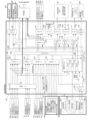
図3は、遊技機10の遊技制御系のブロック図である。遊技機10は遊技制御装置10
0(主基板)を備え、遊技制御装置100は、遊技を統括的に制御する主制御装置(主基
板)であって、遊技用マイクロコンピュータ(以下、遊技用マイコンと称する)111を
有するCPU部110と、入力ポートを有する入力部120と、出力ポートやドライバな
どを有する出力部130、CPU部110と入力部120と出力部130との間を接続す
るデータバス140などからなる。
[Game control device]
FIG. 3 is a block diagram of the gaming control system of the
0 (main board), the
CPU部110は、アミューズメントチップ(IC)と呼ばれる遊技用マイコン(CP
U)111と、水晶振動子のような発振子を備え、CPUの動作クロックやタイマ割込み
、乱数生成回路の基準となるクロックを生成する発振回路(水晶発振器)113などを有
する。遊技制御装置100及び該遊技制御装置100によって駆動されるソレノイドやモ
ータなどの電子部品には、電源装置400で生成されたDC32V,DC12V,DC5
Vなど所定のレベルの直流電圧が供給されて動作可能にされる。
The
U) 111, and an oscillation circuit (crystal oscillator) 113 that includes an oscillator such as a crystal oscillator and generates a reference clock for a CPU operating clock, timer interrupt, and random number generation circuit. The
A DC voltage of a predetermined level, such as V, is supplied to enable operation.
電源装置400は、24Vの交流電源からDC32Vの直流電圧を生成するACDCコ
ンバータやDC32Vの電圧からDC12V,DC5Vなどのより低いレベルの直流電圧
を生成するDC-DCコンバータなどを有する通常電源部410と、遊技用マイコン11
1の内部のRAMに対して停電時に電源電圧を供給するバックアップ電源部420と、停
電監視回路を有し、遊技制御装置100に停電の発生、回復を知らせる停電監視信号やリ
セット信号などの制御信号を生成して出力する制御信号生成部430などを備える。
The
It has a backup
本実施形態では、電源装置400は、遊技制御装置100と別個に構成されているが、
バックアップ電源部420及び制御信号生成部430は、別個の基板上あるいは遊技制御
装置100と一体、すなわち、主基板上に設けるように構成してもよい。遊技盤30及び
遊技制御装置100は機種変更の際に交換の対象となるので、実施例のように、電源装置
400若しくは主基板とは別の基板にバックアップ電源部420及び制御信号生成部43
0を設けることにより、交換の対象から外しコストダウンを図ることができる。
In this embodiment, the
The backup
By providing 0, it is possible to exclude it from replacement and reduce costs.
バックアップ電源部420は、電解コンデンサのような大容量のコンデンサ1つで構成
することができる。バックアップ電源は、遊技制御装置100の遊技用マイコン111(
特に内蔵RAM)に供給され、停電中あるいは電源遮断後もRAMに記憶されたデータが
保持されるようになっている。制御信号生成部430は、例えば通常電源部410で生成
された32Vの電圧を監視してそれが例えば17V以下に下がると停電発生を検出して停
電監視信号を変化させるとともに、所定時間後にリセット信号を出力する。また、電源投
入時や停電回復時にもその時点から所定時間経過後にリセット信号を出力する。
The backup
In particular, the data stored in the RAM is maintained even during a power outage or after the power is cut off. The control
また、遊技制御装置100にはRAM初期化スイッチ112が設けられている。RAM
初期化スイッチ112が押下げられてオン操作されると初期化スイッチ信号が生成され、
これに基づき遊技用マイコン111内のRAM111c及び払出制御装置200内のRA
Mに記憶されている情報を強制的に初期化する処理が行われる。特に限定されるわけでは
ないが初期化スイッチ信号は電源投入時に読み込まれ、停電監視信号は遊技用マイコン1
11が実行するメインプログラムのメインループの中で繰り返し読み込まれる。リセット
信号は強制割込み信号の一種であり、制御システム全体をリセットさせる。
Further, the
When the
Based on this, the
A process of forcibly initializing the information stored in M is performed. Although not particularly limited, the initialization switch signal is read when the power is turned on, and the power failure monitoring signal is read from the
11 is repeatedly read in the main loop of the main program executed. The reset signal is a type of forced interrupt signal and causes the entire control system to be reset.
また、遊技制御装置100(主基板)は、設定キースイッチ93を備える。設定キース
イッチ93は、操作者の回転操作等によってオンすることによって遊技条件(遊技)に関
する設定に応じた確率設定値(設定値)を変更可能な状態にする。なお、RAM初期化ス
イッチ112は、操作者の操作に応じて確率設定値を変更可能な設定値変更スイッチとし
ても使用可能である。本実施形態では、確率設定値は、大当り確率や小当り確率などの当
選確率を設定するための設定値であるが、確率以外の他の遊技条件(演出など)も確率設
定値に応じて変更可能である。設定キースイッチ93とRAM初期化スイッチ112は、
遊技条件に関する設定(確率設定値)を変更可能な設定変更手段(設定変更装置42)を
構成する。なお、RAM初期化スイッチ112ではなく、他のスイッチが、設定値変更ス
イッチを兼用してもよいし、専用に独自の設定値変更スイッチを設けてもよい。
Further, the game control device 100 (main board) includes a setting
A setting changing means (setting changing device 42) capable of changing settings related to gaming conditions (probability setting values) is constituted. Note that another switch instead of the
設定キースイッチ93とRAM初期化スイッチ112は、遊技機10内部の遊技制御装
置100上に設けられることによって、前面枠12(本体枠)が開放されなければ操作で
きない位置(アクセスできない位置)に配置される。即ち、一般の遊技者は、設定キース
イッチ93とRAM初期化スイッチ112にアクセスして操作することができない。
The setting
後述するように、遊技機10の電源投入(停電復旧、復電)の際に、遊技機10は、設
定キースイッチ93とRAM初期化スイッチ112のオン/オフ状態に応じて、確率設定
値を変更可能な設定可変状態(設定変更状態、設定変更モード)、確率設定値を確認可能
な設定確認状態(設定確認モード)などの各種状態に、移行することができる。
As will be described later, when the
本実施形態において、確率設定値は、例えば6段階で規定され、確率設定値1(設定1
)、確率設定値2(設定2)、確率設定値3(設定3)、確率設定値4(設定4)、確率
設定値5(設定5)、確率設定値6(設定6)がある。一般的に、設定1が遊技者に最も
不利な設定であり、設定6が遊技者に最も有利な設定である。設定1、2が低設定であり
、設定3、4が中間の設定(中間設定)であり、設定5、6が高設定である。
In this embodiment, the probability setting value is defined in six stages, for example, and probability setting value 1 (setting 1
), probability setting value 2 (setting 2), probability setting value 3 (setting 3), probability setting value 4 (setting 4), probability setting value 5 (setting 5), and probability setting value 6 (setting 6). Generally, setting 1 is the most disadvantageous setting for the player, and setting 6 is the most advantageous setting for the player.
確率設定変更処理では、操作者によってRAM初期化スイッチ112が押下操作される
度に、作業用設定値領域の作業用設定値(設定)が、設定値0(設定1、確率設定値1)
→設定値1(設定2、確率設定値2)→設定値2(設定3、確率設定値3)→設定値3(
設定4、確率設定値4)→設定値4(設定5、確率設定値5)→設定値5(設定6、確率
設定値6)→設定値0(設定1)→設定値1(設定2)→・・・のように変更される。こ
のように、RAM初期化スイッチ112は、設定値変更スイッチとしても機能する。なお
、説明の都合上、設定変更状態(設定変更モード)中に、作業用設定値0~5をそれぞれ
確率設定値1~6に対応して設けるが、作業用設定値と確率設定値は同じ数値範囲(即ち
0~5又は1~6)に揃えて同じものとして取り扱ってもよい(作業用設定値と確率設定
値を同じ数値にする)。
In the probability setting change process, each time the
→ Setting value 1 (
なお、RAM初期化スイッチ112(設定値変更スイッチ)の操作ではなく、設定キー
スイッチ93を所定の位置に回転操作して確率設定値を変更する構成としてもよい。また
、確率設定値は6段階に限られない。そして、選択されている0~5の作業用設定値に対
応する表示用確率設定値が、例えば4桁の7セグメント型(ドットDpを含めると8セグ
メント型)の表示器である性能表示装置152等に表示される。
Note that the probability setting value may be changed by rotating the setting
遊技用マイコン111は、CPU(中央処理ユニット:マイクロプロセッサ)111a
、読出し専用のROM(リードオンリメモリ)111b及び随時読出し書込み可能なRA
M(ランダムアクセスメモリ)111cを備える。
The
, a read-only ROM (read-only memory) 111b and an RA that can be read and written at any time.
M (random access memory) 111c is provided.
ROM111bは、遊技制御のための不変の情報(プログラム、固定データ、各種乱数
の判定値等)を不揮発的に記憶する。RAM111cは、遊技制御時にCPU111aの
作業領域や各種信号や乱数値の記憶領域として利用されるもので、遊技に関する情報(遊
技情報)が記憶され、停電が発生しても記憶された情報の記憶保持が可能な保持記憶手段
となる。ROM111b又はRAM111cとして、EEPROMのような電気的に書換
え可能な不揮発性メモリを用いてもよい。
The
また、ROM111bは、例えば、特図変動表示ゲームの実行時間、演出内容、リーチ
状態の発生の有無などを規定する変動パターン(変動態様)を決定するための変動パター
ンテーブルを記憶している。変動パターンテーブルとは、始動記憶として記憶されている
変動パターン乱数1~3をCPU111aが参照して変動パターンを決定するためのテー
ブルである。また、変動パターンテーブルには、結果がはずれとなる場合に選択されるは
ずれ変動パターンテーブル、結果が大当りとなる場合に選択される大当り変動パターンテ
ーブル等が含まれる。さらに、これらのパターンテーブルには、リーチ状態となった後の
変動パターンである後半変動パターンを決定するためのテーブル(後半変動グループテー
ブルや後半変動パターン選択テーブル等)、リーチ状態となる前の変動パターンである前
半変動パターンを決定するためのテーブル(前半変動グループテーブルや前半変動パター
ン選択テーブル等)が含まれている。
Further, the
ここでリーチ(リーチ状態)とは、表示状態が変化可能な表示装置を有し、該表示装置
が時期を異ならせて複数の表示結果を導出表示し、該複数の表示結果が予め定められた特
別結果態様となった場合に、遊技状態が遊技者にとって有利な遊技状態(特別遊技状態)
となる遊技機10において、複数の表示結果の一部がまだ導出表示されていない段階で、
既に導出表示されている表示結果が特別結果態様となる条件を満たしている表示状態をい
う。また、別の表現をすれば、リーチ状態とは、表示装置の変動表示制御が進行して表示
結果が導出表示される前段階にまで達した時点でも、特別結果態様となる表示条件からは
ずれていない表示態様をいう。そして、例えば、特別結果態様が揃った状態を維持しなが
ら複数の変動表示領域による変動表示を行う状態(いわゆる全回転リーチ)もリーチ状態
に含まれる。また、リーチ状態とは、表示装置の表示制御が進行して表示結果が導出表示
される前段階にまで達した時点での表示状態であって、表示結果が導出表示される以前に
決定されている複数の変動表示領域の表示結果の少なくとも一部が特別結果態様となる条
件を満たしている場合の表示状態をいう。
Here, reach (ready-to-reach state) means that the display device has a display device whose display state can be changed, the display device derives and displays multiple display results at different times, and the multiple display results are predetermined. A gaming state in which the gaming state is advantageous to the player when a special result mode occurs (special gaming state)
In the
This is a display state in which the display result that has already been derived and displayed satisfies the conditions for the special result mode. In other words, the reach state means that even when the variable display control of the display device has progressed to the stage before the display results are derived and displayed, the display conditions for the special result mode have not been met. This refers to the display mode that does not exist. For example, a state in which variable display is performed using a plurality of variable display areas while maintaining a state in which the special result aspect is complete (so-called full rotation reach) is also included in the reach state. Furthermore, the reach state is the display state at the point when the display control of the display device has progressed to the stage before the display results are derived and displayed, and is determined before the display results are derived and displayed. A display state in which at least some of the display results of a plurality of variable display areas satisfy the conditions for the special result mode.
よって、例えば、特図変動表示ゲームに対応して表示装置に表示される飾り特図変動表
示ゲームが、表示装置における左、中、右の変動表示領域の各々で所定時間複数の識別情
報を変動表示した後、左、右、中の順で変動表示を停止して結果態様を表示するものであ
る場合、左、右の変動表示領域で、特別結果態様となる条件を満たした状態(例えば、同
一の識別情報)で変動表示が停止した状態がリーチ状態となる。他に、すべての変動表示
領域の変動表示を一旦停止した時点で、左、中、右のうちいずれか二つの変動表示領域で
特別結果態様となる条件を満たした状態(例えば、同一の識別情報となった状態、ただし
特別結果態様は除く)をリーチ状態とし、リーチ状態から残りの一つの変動表示領域を変
動表示するようにしてもよい。
Therefore, for example, a decorative special figure variable display game displayed on a display device in response to a special figure variable display game may vary a plurality of pieces of identification information for a predetermined time in each of the left, middle, and right variable display areas of the display device. After displaying, if the variable display is to be stopped in the left, right, and middle order to display the result mode, the left and right variable display areas will display a state where the conditions for the special result mode are met (for example, The state in which the variable display stops with the same identification information is the reach state. In addition, when the variable display of all variable display areas is temporarily stopped, any two of the left, middle, and right variable display areas meet the conditions for the special result mode (for example, the same identification information (However, special result modes are excluded) may be set as a ready-to-win state, and the remaining variable display area may be displayed in a variable manner from the ready-to-reach state.
そして、リーチ状態には複数のリーチ演出が含まれ、特別結果態様(大当り態様)が導
出される可能性が異なる(期待度が異なる)リーチ演出の系統(種類)として、ノーマル
リーチ(Nリーチ)、スペシャル1リーチ(SP1リーチ)、スペシャル2リーチ(SP
2リーチ)、スペシャル3リーチ(SP3リーチ)、プレミアリーチが設定されている。
なお、大当りの期待度(期待値)は、リーチなし<ノーマルリーチ<スペシャル1リーチ
<スペシャル2リーチ<スペシャル3リーチ<プレミアリーチの順に高くなるようになっ
ている。また、リーチ状態は、少なくとも特図変動表示ゲームで特別結果態様が導出され
る場合(大当りとなる場合)における変動表示態様に含まれるようになっている。すなわ
ち、特図変動表示ゲームで特別結果態様が導出されないと判定する場合(はずれとなる場
合)における変動表示態様に含まれることもある。よって、リーチ状態が発生した状態は
、リーチ状態が発生しない場合と比較して大当りとなる可能性の高い状態である。
The reach state includes multiple reach performances, and the systems (types) of reach performances with different possibilities (different expectations) of deriving a special result mode (jackpot mode) are normal reach (N reach),
2 Reach),
Note that the expectation level (expected value) of a jackpot increases in the following order: No reach < Normal reach < Special 1 reach < Special 2 reach < Special 3 reach < Premier reach. Moreover, the reach state is included in the variable display mode at least when a special result mode is derived in the special symbol variable display game (when it becomes a jackpot). That is, it may be included in the variable display mode when it is determined that the special result mode is not derived in the special figure variable display game (when the result is a loss). Therefore, a state in which a ready-to-win state occurs is a state in which there is a high possibility of a jackpot compared to a case in which a ready-to-reach state does not occur.
CPU111aは、ROM111b内の遊技制御用プログラムを実行して、払出制御装
置200や演出制御装置300に対する制御信号(コマンド)を生成したりソレノイドや
表示装置の駆動信号を生成して出力して遊技機10全体の制御を行う。また、図示しない
が、遊技用マイコン111は、特図変動表示ゲームの大当りを判定するための大当り乱数
や大当りの図柄を決定するための大当り図柄乱数、小当りの図柄を決定するための小当り
図柄乱数、特図変動表示ゲームでの変動パターン(各種リーチやリーチなしの変動表示に
おける変動表示ゲームの実行時間等を含む)を決定するための変動パターン乱数等を生成
するための乱数生成回路と、発振回路113からの発振信号(原クロック信号)に基づい
てCPU111aに対する所定周期(例えば、4msec(ミリ秒))のタイマ割込み信
号や乱数生成回路の更新タイミングを与えるクロックを生成するクロックジェネレータを
備えている。
The
また、CPU111aは、特図変動表示ゲームに関する処理において、ROM111b
に記憶されている複数の変動パターンテーブルの中から、いずれか一の変動パターンテー
ブルを取得する。具体的には、CPU111aは、特図変動表示ゲームの遊技結果(大当
りあるいははずれ)や、現在の遊技状態としての特図変動表示ゲームの確率状態(通常確
率状態あるいは高確率状態)、始動記憶数などに基づいて、複数の変動パターンテーブル
の中から、いずれか一の変動パターンテーブルを選択して取得する。ここで、CPU11
1aは、特図変動表示ゲームを実行する場合に、ROM111bに記憶された複数の変動
パターンテーブルのうち、いずれか一の変動パターンテーブルを取得する変動振り分け情
報取得手段をなす。
In addition, the
Any one of the plurality of variation pattern tables stored in the memory is acquired. Specifically, the
1a constitutes a fluctuation distribution information acquisition means for acquiring any one of the plurality of fluctuation pattern tables stored in the
払出制御装置200は、CPU、ROM、RAM、入力インタフェース、出力インタフ
ェース等を備え、遊技制御装置100からの賞球払出し指令(コマンドやデータ)に従っ
て、払出ユニットの払出モータ91を駆動させ、賞球を払い出させるための制御を行う。
また、払出制御装置200は、カードユニット600からの貸球要求信号に基づいて払出
ユニットの払出モータ91を駆動させ、貸球を払い出させるための制御を行う。
The
Further, the
遊技用マイコン111の入力部120には、遊技機に対する電波の発射を検出する電波
センサ62(盤電波センサ)、普図始動ゲート34のゲートスイッチ34a、第1始動入
賞口36内の始動口1スイッチ36a、第2始動入賞口37(普通変動入賞装置)内の始
動口2スイッチ37a、一般入賞口35の入賞口スイッチ35a、特別変動入賞装置38
、39の大入賞口スイッチ43(下大入賞口スイッチ38a、上大入賞口スイッチ39a
)に接続され、これらのスイッチから供給されるハイレベルが11Vでロウレベルが7V
のような負論理の信号が入力され、0V-5Vの正論理の信号に変換するインタフェース
チップ(近接I/F)121が設けられている。
The
, 39 big winning opening switch 43 (lower big winning opening switch 38a, upper big winning opening switch 39a
), and the high level supplied from these switches is 11V and the low level is 7V.
An interface chip (proximity I/F) 121 is provided which inputs a negative logic signal such as 0V to 5V and converts it into a positive logic signal of 0V to 5V.
さらに、インタフェースチップ(近接I/F)121は、特定領域スイッチ72、残存
球排出口スイッチ73、アウト球検出スイッチ74に接続される。特定領域スイッチ72
は、特定領域86(V入賞口)への遊技球の通過(V入賞)を検出する。残存球排出口ス
イッチ73は、特別変動入賞装置38、39からの遊技球を排出する残存球排出口を通過
した遊技球を検出する。アウト球検出スイッチ74は、アウト口30bを通過する遊技球
のみを検出してもよいし、遊技領域に発射されて遊技を終えた全ての遊技球を検出しても
よい。
Further, the interface chip (proximity I/F) 121 is connected to a
detects passage of the game ball (V winning hole) to the specific area 86 (V winning hole). The remaining ball
近接I/F121の出力は、第2入力ポート123、第3入力ポート124、又は、第
4入力ポート126に供給されデータバス140を介して遊技用マイコン111に読み込
まれる。なお、近接I/F121の出力のうち、ゲートスイッチ34a、始動口1スイッ
チ36a、始動口2スイッチ37a、入賞口スイッチ35a、大入賞口スイッチ43の検
出信号は第3入力ポート124に入力される。
The output of the proximity I/
また、近接I/F121の出力のうち、電波センサ62の検出信号及びセンサやスイッ
チの異常を検出した際に出力される異常検知信号は第2入力ポート123に入力される。
Further, among the outputs of the proximity I/
また、近接I/F121の出力のうち、特定領域スイッチ72、残存球排出口スイッチ
73、又は、アウト球検出スイッチ74の検出信号は第4入力ポート126に入力される
。
Furthermore, among the outputs of the proximity I/
また、第2入力ポート123には、遊技機10の前面枠12等に設けられた不正検出用
の磁気センサスイッチ61の検出信号、遊技機10のガラス枠15等に設けられたガラス
枠開放検出スイッチ63、前面枠12(本体枠)等に設けられた前面枠開放検出スイッチ
64(本体枠開放検出スイッチ)からの信号、遊技機10の振動を検出する振動センサ6
5からの信号が入力される。
The
A signal from 5 is input.
また、第2入力ポート123は、設定キースイッチ93からの設定キースイッチ信号を
取り込んでデータバス140を介して遊技用マイコン111に供給する。
Further, the
また、近接I/F121の出力のうち、第3入力ポート124への出力は、遊技制御装
置100から中継基板70を介して図示しない試射試験装置へも供給されるようになって
いる。さらに、近接I/F121の出力のうち始動口1スイッチ36aと始動口2スイッ
チ37aの検出信号は、第3入力ポート124の他、遊技用マイコン111に入力される
ように構成されている。
Further, among the outputs of the proximity I/
前述のように近接I/F121は、信号のレベル変換機能を有する。このようなレベル
変換機能を可能にするため、近接I/F121には、電源装置400から通常のICの動
作に必要な例えば5Vのような電圧の他に、12Vの電圧が供給されるようになっている
。
As described above, the proximity I/
第3入力ポート124が保持しているデータは、遊技用マイコン111が第3入力ポー
ト124に割り当てられているアドレスをデコードすることによってイネーブル信号CE
2をアサート(有効レベルに変化)することよって、読み出すことができる。第2入力ポ
ート123、第4入力ポート126や後述の第1入力ポート122も同様である。
The data held by the
It can be read by asserting 2 (changing to valid level). The same applies to the
また、入力部120には、払出制御装置200から出力される枠電波不正信号、払出ビ
ジー信号、払出異常を示すステータス信号、払出前の遊技球の不足を示すシュート球切れ
スイッチ信号、オーバーフローを示すオーバーフロースイッチ信号、操作ハンドル24に
設けられたタッチスイッチの入力に基づくタッチスイッチ信号、RAM初期化スイッチ1
12からの信号を取り込んでデータバス140を介して遊技用マイコン111に供給する
第1入力ポート122が設けられている。オーバーフロースイッチ信号は、下皿23に遊
技球が所定量以上貯留されていること(満杯になったこと)を検出したときに出力される
信号である。枠電波不正信号は前面枠12(本体枠)に設けられた枠電波センサが電波を
検出することに基づき出力される信号であり、払出ビジー信号は払出制御装置200がコ
マンドを受付可能な状態か否かを示す信号である。
The
A
また、入力部120には、電源装置400からの停電監視信号やリセット信号などの信
号を遊技用マイコン111等に入力するためのシュミットバッファ125が設けられてお
り、シュミットバッファ125はこれらの入力信号からノイズを除去する機能を有する。
電源装置400からの停電監視信号は、一旦第1入力ポート122に入力され、データバ
ス140を介して遊技用マイコン111に取り込まれる。つまり、前述の各種スイッチか
らの信号と同等の信号として扱われる。遊技用マイコン111に設けられている外部から
の信号を受ける端子の数には制約があるためである。
In addition, the
A power failure monitoring signal from the
一方、シュミットバッファ125によりノイズ除去されたリセット信号RSTは、遊技
用マイコン111に設けられているリセット端子に直接入力されるとともに、出力部13
0の各ポートに供給される。また、リセット信号RSTは出力部130を介さずに直接中
継基板70に出力することで、試射試験装置に出力するために中継基板70のポート(図
示省略)に保持される試射試験信号をオフするように構成されている。
On the other hand, the reset signal RST from which noise has been removed by the
0 ports. In addition, by outputting the reset signal RST directly to the
また、リセット信号RSTを中継基板70を介して試射試験装置に出力可能に構成する
ようにしてもよい。なお、リセット信号RSTは入力部120の各ポート122,123
,124には供給されない。リセット信号RSTが入る直前に遊技用マイコン111によ
って出力部130の各ポートに設定されたデータはシステムの誤動作を防止するためリセ
ットする必要があるが、リセット信号RSTが入る直前に入力部120の各ポートから遊
技用マイコン111が読み込んだデータは、遊技用マイコン111のリセットによって廃
棄されるためである。
Further, the configuration may be such that the reset signal RST can be output to the sight test equipment via the
, 124. The data set to each port of the
出力部130には、遊技用マイコン111から演出制御装置300への通信経路及び遊
技用マイコン111から払出制御装置200への通信経路に配されるシュミットバッファ
132が設けられている。遊技制御装置100から演出制御装置300及び払出制御装置
200へは、シリアル通信でデータが送信される。なお、演出制御装置300の側から遊
技制御装置100へ信号を入力できないようにした片方向通信とされている。
The
さらに、出力部130には、データバス140に接続され図示しない認定機関の試射試
験装置へ変動表示ゲームの特図図柄情報を知らせるデータや大当りの確率状態を示す信号
などを中継基板70を介して出力するバッファ133が実装可能に構成されている。バッ
ファ133は遊技店に設置される実機(量産販売品)としてのパチンコ遊技機の遊技制御
装置(主基板)には実装されない部品である。なお、前記近接I/F121から出力され
る始動口スイッチなど加工の必要のないスイッチの検出信号は、バッファ133を通さず
に中継基板70を介して試射試験装置に供給される。
Further, the
一方、磁気センサスイッチ61や電波センサ62のようにそのままでは試射試験装置に
供給できない検出信号は、一旦遊技用マイコン111に取り込まれて他の信号若しくは情
報に加工されて、例えば遊技機が遊技制御できない状態であることを示すエラー信号とし
てデータバス140からバッファ133、中継基板70を介して試射試験装置に供給され
る。
On the other hand, detection signals such as those from the
なお、中継基板70には、バッファ133から出力された信号を取り込んで試射試験装
置に供給するポートや、バッファを介さないスイッチの検出信号の信号線を中継して伝達
するコネクタなどが設けられている。中継基板70上のポートには、遊技用マイコン11
1から出力されるチップイネーブル信号CEも供給され、該信号CEにより選択制御され
たポートの信号が試射試験装置に供給されるようになっている。
Note that the
A chip enable signal CE outputted from 1 is also supplied, and signals of ports selectively controlled by the signal CE are supplied to the sight test equipment.
また、出力部130には、データバス140に接続され普通変動入賞装置37を開放さ
せるソレノイド(普電ソレノイド)37c、第1特別変動入賞装置38を開放させる下大
入賞口ソレノイド38b(大入賞口ソレノイド1)、第2特別変動入賞装置39を開放さ
せる上大入賞口ソレノイド39b(大入賞口ソレノイド2)、レバーを動作させ特定領域
86を開放させるレバーソレノイド86bの開閉データを出力するための第2出力ポート
134が設けられている。
The
また、出力部130には、一括表示装置50に表示する内容に応じてLEDのアノード
端子が接続されているセグメント線のオン/オフデータを出力するための第3出力ポート
135、一括表示装置50のLEDのカソード端子が接続されているデジット線のオン/
オフデータを出力するための第4出力ポート136が設けられている。
Further, the
A fourth output port 136 is provided for outputting off data.
また、出力部130には、大当り情報など遊技機10に関する情報を外部情報端子71
に出力するための第5出力ポート137が設けられている。外部情報端子71にはフォト
リレーが備えられ、例えば遊技店に設置された外部装置(情報収集端末や遊技場内部管理
装置(ホールコンピュータ)など)に接続可能であり、遊技機10に関する情報を外部装
置に供給することができるようになっている。また、第5出力ポート137からはシュミ
ットバッファ132を介して払出制御装置200に発射許可信号も出力される。
The
A
さらに、出力部130には、第2出力ポート134から出力される普電ソレノイド37
cや大入賞口ソレノイド38b、39bなどの開閉データ信号を受けてソレノイド駆動信
号を生成し出力する第1ドライバ(駆動回路)138a、第3出力ポート135から出力
される一括表示装置50の電流供給側のセグメント線のオン/オフ駆動信号を出力する第
2ドライバ138b、第4出力ポート136から出力される一括表示装置50の電流引き
込み側のデジット線のオン/オフ駆動信号を出力する第3ドライバ138c、第5出力ポ
ート137から管理装置等の外部装置に供給する外部情報信号を外部情報端子71に出力
する第4ドライバ138dが設けられている。
Furthermore, the
The first driver (drive circuit) 138a receives the opening/closing data signals of the big
第1ドライバ138aには、32Vで動作するソレノイドを駆動できるようにするため
、電源電圧としてDC32Vが電源装置400から供給される。また、一括表示装置50
のセグメント線を駆動する第2ドライバ138bには、DC12Vが供給される。デジッ
ト線を駆動する第3ドライバ138cは、表示データに応じたデジット線を電流で引き抜
くためのものであるため、電源電圧は12V又は5Vのいずれであってもよい。
The
12Vを出力する第2ドライバ138bによりセグメント線を介してLEDのアノード
端子に電流を流し込み、接地電位を出力する第3ドライバ138cによりカソード端子よ
りセグメント線を介して電流を引き抜くことで、ダイナミック駆動方式で順次選択された
LEDに電源電圧が流れて点灯される。外部情報信号を外部情報端子71に出力する第4
ドライバ138dは、外部情報信号に12Vのレベルを与えるため、DC12Vが供給さ
れる。なお、バッファ133や第2出力ポート134、第1ドライバ138a等は、遊技
制御装置100の出力部130、すなわち、主基板ではなく、中継基板70側に設けるよ
うにしてもよい。
The
The
さらに、出力部130には、外部の検査装置500へ各遊技機の識別コードやプログラ
ムなどの情報を送信するためのフォトカプラ139が設けられている。フォトカプラ13
9は、遊技用マイコン111が検査装置500との間でシリアル通信によってデータの送
受信を行えるように双方通信可能に構成されている。なお、かかるデータの送受信は、通
常の汎用マイクロプロセッサと同様に遊技用マイコン111が有するシリアル通信端子を
利用して行われるため、入力ポート122,123,124のようなポートは設けられて
いない。
Further, the
Reference numeral 9 is configured to enable mutual communication between the
さらに、出力部130には、第2出力ポート134から出力されるシリアルデータ(制
御用データ、点灯パターンデータ、キャラクタコード(文字コード)など)を受けて、性
能表示装置152(状態表示装置)を駆動するドライバ150が設けられている。本実施
形態では、性能表示装置152は、複数(4つ)の7セグメント型(ドットDpを含める
と8セグメント型)の表示器(LEDランプ)からなり、ドライバ150はLEDドライ
バであるが、これに限られるものではない。
Furthermore, the
性能表示装置152は、遊技制御装置100(主基板)上に設けられるものであるが、
他の場所に設けられてもよい。例えば、性能表示装置152は、表示用確率設定値や役物
比率や出玉率や排出球数を表示可能である。
The
It may also be provided at other locations. For example, the
ここで、排出球数は、遊技領域32から排出された遊技球の数(アウト球数とも呼ぶ)
であり、入賞口を通過した遊技球の数(入賞数)とアウト口30bを通過した遊技球の数
との合計である。排出球数は、アウト球検出スイッチ74の信号などをカウント(計数)
することにより取得できる。本実施形態では、入賞口には、一般入賞口35、始動入賞口
36(第1始動入賞口、始動口1)、普通変動入賞装置37(第2始動入賞口、始動口2
)、及び、特別変動入賞装置38、39(大入賞口)が含まれる。
Here, the number of ejected balls is the number of game balls ejected from the game area 32 (also called the number of out balls)
This is the total of the number of game balls that passed through the winning opening (number of winnings) and the number of gaming balls that passed through the
It can be obtained by In this embodiment, the winning openings include a general winning
), and special variable winning
出玉率は、排出球数(或は発射球数)に対する賞球数の合計の比率(割合)であり、(
獲得球数÷排出球数)×100(%)で計算される。即ち、出玉率は、排出球数100個
当りの獲得球数(賞球数の合計)となる。
The ball output rate is the ratio (ratio) of the total number of prize balls to the number of balls ejected (or number of balls fired), and (
Calculated as: number of pitches acquired ÷ number of pitches released) x 100 (%). That is, the ball output rate is the number of balls acquired (total number of prize balls) per 100 balls ejected.
例えば、役物比率は、所定期間(例えば、遊技機10の電源投入から現在まで)に入賞
口に入賞したことで得られた全賞球数(賞球の合計数)のうち、大当り状態中に大入賞口
に入賞したことで得られた賞球数(役物別獲得球数)の割合(%)(=いわゆる連続役物
比率)である。なお、役物比率は、全賞球数のうち、大入賞口に入賞したことで得られた
賞球数(大当り状態中と小当り状態中)の割合(=大入賞口比率)でもよいし、或は、大
入賞口及び普通変動入賞装置37(第2始動入賞口)に入賞したことで得られた賞球数の
割合(=一般的に使用されるいわゆる役物比率(全役物比率))でもよい。
For example, the accessory ratio is the total number of prize balls (total number of prize balls) obtained by entering the winning slot in a predetermined period (for example, from the power-on of the
〔演出制御装置〕
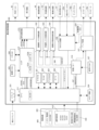
次に、図4を用いて、演出制御装置300(サブ基板)の構成について説明する。図4
は、遊技機10の演出制御系のブロック図である。
[Production control device]
Next, the configuration of the production control device 300 (subboard) will be explained using FIG. 4. Figure 4
1 is a block diagram of the production control system of the
演出制御装置300は、遊技用マイコン111と同様にアミューズメントチップ(IC
)からなる主制御用マイコン(CPU)311と、主制御用マイコン311からのコマン
ドやデータに従って表示装置41への映像表示のための画像処理を行うグラフィックプロ
セッサとしてのVDP(Video Display Processor)312と、各種のメロディや効果音
などをスピーカ19から再生させるため音の出力を制御する音源LSI314を備えてい
る。
The
), and a VDP (Video Display Processor) 312 as a graphic processor that performs image processing for displaying video on the
主制御用マイコン311には、CPUが実行するプログラムや各種データを格納したP
ROM(プログラマブルリードオンリメモリ)からなるプログラムROM321、作業領
域を提供するRAM322、停電時に電力が供給されなくとも記憶内容を保持可能なFe
RAM323、現在の日時(年月日や曜日、時刻など)を示す情報を生成する計時手段を
なすRTC(リアルタイムクロック)338が接続されている。なお、主制御用マイコン
311の内部にも作業領域を提供するRAMが設けられている。
The
A
The
また、主制御用マイコン311にはWDT(ウォッチドッグ・タイマ)回路324が接
続されている。主制御用マイコン311は、遊技用マイコン111からのコマンドを解析
し、演出内容を決定してVDP312に出力映像の内容を指示したり、音源LSI314
への再生音の指示、装飾ランプの点灯、モータやソレノイドの駆動制御、演出時間の管理
などの処理を実行する。
Further, a WDT (watchdog timer)
It performs processing such as instructing the playback of sounds, lighting decorative lamps, controlling the drive of motors and solenoids, and managing performance time.
VDP312には、作業領域を提供するRAM312aや、画像を拡大、縮小処理する
ためのスケーラ312bが設けられている。また、VDP312にはキャラクタ画像や映
像データが記憶された画像ROM325や、画像ROM325から読み出されたキャラク
タなどの画像データを展開したり加工したりするのに使用される超高速なVRAM(ビデ
オRAM)326が接続されている。
The
特に限定されるわけではないが、主制御用マイコン311とVDP312との間は、パ
ラレル方式でデータの送受信が行われるように構成されている。パラレル方式でデータを
送受信することで、シリアルの場合よりも短時間にコマンドやデータを送信することがで
きる。
Although not particularly limited, the
VDP312から主制御用マイコン311へは、表示装置41の映像とガラス枠15や
遊技盤30に設けられている装飾ランプの点灯を同期させるための垂直同期信号VSYN
C、データの送信タイミングを与える同期信号STSが入力される。なお、VDP312
から主制御用マイコン311へは、VRAMへの描画の終了等処理状況を知らせるため割
込み信号INT0~n及び主制御用マイコン311からのコマンドやデータの受信待ちの
状態にあることを知らせるためのウェイト信号WAITなども入力される。
A vertical synchronization signal VSYN is sent from the
C. A synchronization signal STS that provides data transmission timing is input. In addition, VDP312
The
演出制御装置300には、LVDS(小振幅信号伝送)方式で表示装置41に送信する
映像信号を生成する信号変換回路313が設けられている。VDP312から信号変換回
路313へは、映像データ、水平同期信号HSYNC及び垂直同期信号VSYNCが入力
されるようになっており、VDP312で生成された映像は、信号変換回路313を介し
て表示装置41に表示される。
The
音源LSI314には音声データが記憶された音ROM327が接続されている。主制
御用マイコン311と音源LSI314は、アドレス/データバス340を介して接続さ
れている。また、音源LSI314から主制御用マイコン311へは割込み信号INTが
入力されるようになっている。演出制御装置に300には、ガラス枠15に設けられた上
スピーカ19a及び前面枠12に設けられた下スピーカ19bを駆動するオーディオパワ
ーアンプなどからなるアンプ回路337が設けられており、音源LSI314で生成され
た音声はアンプ回路337を介して上スピーカ19a及び下スピーカ19bから出力され
る。
A
また、演出制御装置300には、遊技制御装置100から送信されるコマンドを受信す
るインタフェースチップ(コマンドI/F)331が設けられている。コマンドI/F3
31を介して、遊技制御装置100から演出制御装置300に送信された飾り特図保留数
コマンド、飾り特図コマンド、変動コマンド、停止情報コマンド等を、演出制御指令信号
(演出コマンド)として受信する。遊技制御装置100の遊技用マイコン111はDC5
Vで動作し、演出制御装置300の主制御用マイコン311はDC3.3Vで動作するた
め、コマンドI/F331には信号のレベル変換の機能が設けられている。
Further, the
31, receive the decoration special figure reservation number command, decoration special figure command, variation command, stop information command, etc. transmitted from the
Since the
また、演出制御装置300には、遊技盤30(センターケース40を含む)に設けられ
ているLED(発光ダイオード)を有する盤装飾装置46を駆動制御する盤装飾LED制
御回路332、ガラス枠15に設けられているLED(発光ダイオード)を有する枠装飾
装置(例えば枠装飾装置18等)を駆動制御する枠装飾LED制御回路333、遊技盤3
0(センターケース40を含む)に設けられている盤演出装置44(例えば表示装置41
における演出表示と協働して演出効果を高める可動役物等)を駆動制御する盤演出可動体
制御回路334が設けられている。なお、盤装飾装置46には、前述のランプ表示装置8
0が含まれてよい。
The
0 (including the center case 40)
A board performance movable
May contain 0.
ランプやモータ及びソレノイドなどを駆動制御するこれらの制御回路332~334は
、アドレス/データバス340を介して主制御用マイコン311と接続されている。なお
、ガラス枠15に設けられているモータ等の枠演出装置を駆動制御する枠演出可動体制御
回路を備えていてもよい。
These
さらに、演出制御装置300には、ガラス枠15に設けられた演出ボタン25に内蔵さ
れている演出ボタンスイッチ25a、演出ボタン25の表面に設けられているタッチパネ
ル25b、盤演出装置44内のモータの初期位置等を検出する演出役物スイッチ47(演
出モータスイッチ)のオン/オフ状態を検出して主制御用マイコン311に検出信号を入
力する機能や、演出制御装置300に設けられた音量調節スイッチ335の状態を検出し
て主制御用マイコン311に検出信号を入力するスイッチ入力回路336が設けられてい
る。
Furthermore, the
電源装置400の通常電源部410は、前述のような構成を有する演出制御装置300
やそれによって制御される電子部品に対して所望のレベルの直流電圧を供給するため、モ
ータやソレノイドを駆動するためのDC32V、液晶パネルからなる表示装置41、モー
タやLEDを駆動するためのDC12V、コマンドI/F331の電源電圧となるDC5
Vの他に、モータやLED、スピーカを駆動するためのDC15Vの電圧を生成するよう
に構成されている。
The normal
In order to supply a desired level of DC voltage to the electronic components controlled by it, 32V DC to drive the motor and solenoids, a
In addition to V, it is configured to generate a DC 15V voltage for driving a motor, LED, and speaker.
さらに、主制御用マイコン311として、3.3Vあるいは1.2Vのような低電圧で
動作するLSIを使用する場合には、DC5Vに基づいてDC3.3VやDC1.2Vを
生成するためのDC-DCコンバータが演出制御装置300に設けられる。なお、DC-
DCコンバータは通常電源部410に設けるようにしてもよい。
Furthermore, when using an LSI that operates at a low voltage such as 3.3V or 1.2V as the
The DC converter may be provided in the normal
電源装置400の制御信号生成部430により生成されたリセット信号は、主制御用マ
イコン311に供給され、当該デバイスをリセット状態にする。また、主制御用マイコン
311から出力される形で、VDP312(VDPRESET信号)、音源LSI314
、スピーカを駆動するアンプ回路337(SNDRESET信号)、ランプやモータなど
を駆動制御する制御回路332~334(IORESET信号)に供給され、これらをリ
セット状態にする。また、演出制御装置300には遊技機10の各所を冷却する冷却FA
N45が接続され、演出制御装置300の電源が投入された状態では冷却FAN45が駆
動するようにされている。
The reset signal generated by the control
, an amplifier circuit 337 (SNDRESET signal) that drives a speaker, and control
When N45 is connected and the
次に、これらの制御回路において行われる遊技制御について説明する。遊技制御装置1
00の遊技用マイコン111のCPU111aでは、普図始動ゲート34に備えられたゲ
ートスイッチ34aからの遊技球の検出信号の入力に基づき、普図の当り判定用乱数値を
抽出してROM111bに記憶されている判定値と比較し、普図変動表示ゲームの当り外
れを判定する。
Next, game control performed in these control circuits will be explained.
The
そして、普図表示器に、識別図柄を所定時間変動表示した後、停止表示する普図変動表
示ゲームを表示する。普図変動表示ゲームの結果が当りの場合は、普図表示器に特別の結
果態様を表示するとともに、普電ソレノイド37cを動作させ、普通変動入賞装置37の
可動部材37bを所定時間(例えば、0.3秒間)前述のように開放する制御を行う。す
なわち、遊技制御装置100が、変換部材(可動部材37b)の変換制御を行う変換制御
実行手段をなす。なお、普図変動表示ゲームの結果がはずれの場合は、普図表示器にはず
れの結果態様を表示する制御を行う。
Then, a common symbol variation display game is displayed on the common symbol display device, in which the identification symbols are displayed in a variable manner for a predetermined period of time and then stopped. If the result of the general figure fluctuation display game is a win, a special result mode is displayed on the general figure display, and the general
また、始動入賞口36に備えられた始動口1スイッチ36aからの遊技球の検出信号の
入力に基づき始動入賞(始動記憶)を記憶し、始動記憶に基づき、特図1変動表示ゲーム
の大当り判定用乱数値を抽出してROM111bに記憶されている判定値と比較し、特図
1変動表示ゲームの当り外れを判定する。
In addition, the starting prize (starting memory) is stored based on the input of the detection signal of the game ball from the starting
また、普通変動入賞装置37に備えられた始動口2スイッチ37aからの遊技球の検出
信号の入力に基づき始動記憶を記憶し、始動記憶に基づき、特図2変動表示ゲームの大当
り判定用乱数値を抽出してROM111bに記憶されている判定値と比較し、特図2変動
表示ゲームの当り外れを判定する。
In addition, a starting memory is stored based on the input of the game ball detection signal from the starting
そして、遊技制御装置100のCPU111aは、特図1変動表示ゲームや特図2変動
表示ゲームの判定結果を含む制御信号(演出制御コマンド)を、演出制御装置300に出
力する。そして、特図1表示器51や特図2表示器52に、識別図柄を所定時間変動表示
した後、停止表示する特図変動表示ゲームを表示する。すなわち、遊技制御装置100が
、遊技領域32を流下する遊技球の始動入賞領域(第1始動入賞口36、普通変動入賞装
置37)への入賞に基づき変動表示ゲームの進行制御を行う遊技制御手段をなす。
Then, the
また、演出制御装置300では、遊技制御装置100からの制御信号に基づき、表示装
置41で特図変動表示ゲームに対応した飾り特図変動表示ゲームを表示する。さらに、演
出制御装置300では、遊技制御装置100からの制御信号に基づき、演出状態の設定や
、スピーカ19a,19bからの音の出力、各種LEDの発光を制御する処理等を行う。
すなわち、演出制御装置300が、遊技(変動表示ゲーム等)に関する演出を制御する演
出制御手段をなす。
In addition, in the
That is, the
そして、遊技制御装置100のCPU111aは、特図変動表示ゲームの結果が当りの
場合は、特図1表示器51や特図2表示器52に特別結果態様を表示するとともに、特別
遊技状態を発生させる。特別遊技状態を発生させる処理においては、CPU111aは、
例えば、大入賞口ソレノイド39bにより特別変動入賞装置39の開閉扉39cを開放さ
せ、大入賞口内への遊技球の流入を可能とする制御を行う。
Then, if the result of the special figure fluctuation display game is a win, the
For example, the opening/
そして、大入賞口に所定個数(例えば、10個)の遊技球が入賞するか、大入賞口の開
放から所定の開放可能時間(例えば、27秒又は0.05秒)が経過するかのいずれかの
条件が達成されるまで大入賞口を開放することを1ラウンド(R)とし、これを所定ラウ
ンド回数(例えば、15回、11回又は2回)継続する(繰り返す)制御(サイクル遊技
)を行う。すなわち、遊技制御装置100が、停止結果態様が特別結果態様となった場合
に、大入賞口を開閉する制御を行う大入賞口開閉制御手段をなす。また、特図変動表示ゲ
ームの結果がはずれの場合は、特図1表示器51や特図2表示器52にはずれの結果態様
を表示する制御を行う。
Then, either a predetermined number of game balls (for example, 10) enter the grand prize opening, or a predetermined opening time (for example, 27 seconds or 0.05 seconds) elapses after the opening of the grand prize opening. One round (R) is defined as opening the big prize opening until the above condition is achieved, and this is continued (repeated) for a predetermined number of rounds (for example, 15, 11, or 2 times) (cycle game) I do. That is, the
また、遊技制御装置100は、特図変動表示ゲームの結果態様に基づき、特別遊技状態
の終了後に、遊技状態として高確率状態を発生可能となっている。高確率状態(確変状態
)は、特図変動表示ゲームにて当り結果となる確率が、通常確率状態と比較して高い状態
である。また、特図1変動表示ゲーム及び特図2変動表示ゲームのどちらの特図変動表示
ゲームの結果態様に基づき高確率状態となっても、特図1変動表示ゲーム及び特図2変動
表示ゲームの両方が高確率状態となる。
Furthermore, the
また、遊技制御装置100は、特図変動表示ゲームの結果態様に基づき、特別遊技状態
の終了後に、遊技状態として時短状態(特定遊技状態)を発生可能となっている。時短状
態においては、普図変動表示ゲーム及び普通変動入賞装置37を時短動作状態とする制御
を行い、普通変動入賞装置37が通常動作状態である場合よりも、単位時間当りの普通変
動入賞装置37の開放時間が実質的に多くなるように制御するため、普電サポート状態と
なる。なお、潜伏確変状態を除く高確率状態(通常の確変状態)でも、重複して時短状態
にして普電サポート(電サポ)を実行する。
Furthermore, the
例えば、時短状態においては、前述の普図変動表示ゲームの実行時間(普図変動時間)
を通常の第1変動表示時間よりも短い第2変動表示時間にする時間短縮変動が可能である
(例えば、10000msecが1000msec)。なお、時短状態においては、特図
変動表示ゲームの実行時間(特図変動時間)も通常より短縮され、特図変動表示ゲームの
時間短縮変動も実行する。
For example, in the time saving state, the execution time of the above-mentioned normal pattern fluctuation display game (normal pattern fluctuation time)
It is possible to shorten the time by making the second variable display time shorter than the normal first variable display time (for example, 10000 msec becomes 1000 msec). In addition, in the time saving state, the execution time (special figure variation time) of the special figure variation display game is also shortened than usual, and the time reduction variation of the special figure variation display game is also executed.
また、時短状態においては、普図変動表示ゲームの結果を表示する普図停止時間を第1
停止時間(例えば1604msec)よりも短い第2停止時間(例えば704msec)
となるように制御することが可能である。
In addition, in the time saving state, the normal pattern stop time for displaying the result of the general pattern fluctuation display game is set to the first
A second stop time (for example, 704 msec) that is shorter than the stop time (for example, 1604 msec)
It is possible to control so that
また、時短状態においては、普図変動表示ゲームが当り結果となって普通変動入賞装置
37が開放される場合に、開放時間(普電開放時間)が通常状態の第1開放時間(例えば
100msec)よりも長い第2開放時間(例えば1352msec)となるように制御
することが可能である。
In addition, in the time saving state, when the normal
また、時短状態においては、普図変動表示ゲームの1回の当り結果に対して、普通変動
入賞装置37の開放回数(普電開放回数)を第1開放回数(例えば2回)よりも多い回数
(例えば、4回)の第2開放回数に設定することが可能である。また、時短状態において
は、普図変動表示ゲームの当り結果となる確率(普図確率)を通常動作状態である場合の
通常確率(低確率)よりも高い高確率とすることが可能である。
In addition, in the time saving state, the number of times the normal
時短状態においては、普図変動時間、普図停止時間、普電開放回数、普電開放時間、普
図確率のいずれか一つ又は複数を変化させることで普通変動入賞装置37を開状態に状態
変換する時間を通常よりも延長するようにする。これにより、時短状態では、通常遊技状
態よりも普通変動入賞装置37への入賞が容易化して、単位時間当たりの特図変動表示ゲ
ームの実行回数が通常遊技状態よりも増加可能である。また、変化させるものが異なる複
数種類の時短状態を設定することも可能である。また、通常動作状態において可動部材3
7bを開放しないように設定(普図確率が0)してもよい。また、当りとなった場合に第
1開放態様と第2開放態様のいずれかを選択するようにしてもよい。この場合、第1開放
態様と第2開放態様の選択確率を異ならせてもよい。また、高確率状態と時短状態は、そ
れぞれ独立して発生可能であり、両方を同時に発生することも可能であるし一方のみを発
生させることも可能である。
In the short time state, the normal variable
7b may be set not to be opened (normal pattern probability is 0). Furthermore, when a win occurs, either the first opening mode or the second opening mode may be selected. In this case, the selection probabilities for the first opening mode and the second opening mode may be different. Further, the high probability state and the time saving state can be generated independently, and both can be generated at the same time, or only one of them can be generated.
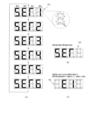
〔電源投入時の移行状態〕
図5は、遊技機10の電源投入(電源復旧)時の移行状態を説明する図である。前述の
ように、電源投入時のRAM初期化スイッチ112及び設定キースイッチ93のオンオフ
状態によって、図5に示すように4つの状態(モード)へ移行する。
[Transition state when power is turned on]
FIG. 5 is a diagram illustrating a transition state when the
まず、電源投入時に、RAM初期化スイッチ112と設定キースイッチ93とがオンに
されている場合には、確率設定値(設定値)を変更可能な設定可変状態(設定変更状態、
設定変更モード)に移行する(図6BのA1027-A1036と図8参照)。
First, when the power is turned on, if the
(see A1027-A1036 in FIG. 6B and FIG. 8).
次に、電源投入時に、設定キースイッチ93がオンにされているがRAM初期化スイッ
チ112がオフの場合には、確率設定値を確認可能な設定確認状態(設定確認モード)に
移行する(図6BのA1031-A1036と図8参照)。
Next, when the power is turned on, if the setting
また、電源投入時に、設定キースイッチ93がオフであるがRAM初期化スイッチ11
2がオンにされている場合には、RAM初期化状態(RAMクリアモード)に移行し、R
AM初期化処理(RAMクリア処理)が実行されて、RAM111cが初期化される(図
6BのA1042-1044参照)。
Also, when the power is turned on, although the setting
2 is turned on, it moves to the RAM initialization state (RAM clear mode) and R
AM initialization processing (RAM clear processing) is executed and the
電源投入時に、設定キースイッチ93とRAM初期化スイッチ112とがオフである場
合には、通常復電状態(通常復電モード)に移行し、単に復電されるだけの状態になる。
When the setting
[遊技制御装置の制御]
以下、このような遊技を行う遊技機の制御について説明する。まず、上記遊技制御装置
100の遊技用マイクロコンピュータ(遊技用マイコン)111によって実行される制御
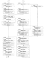
について説明する。遊技用マイコン111による制御処理は、主に図6A及び図6Bに示
すメイン処理と、所定時間周期(本実施形態では4msec(ミリ秒))で行われる図7
に示すタイマ割込み処理とからなる。即ち、遊技用マイコン111の制御処理に対応する
遊技制御用プログラムは、メイン処理に対応するメインプログラム(呼出元ルーチン)と
、タイマ割込み処理に対応する割込み処理プログラム(割込み処理ルーチン)から構成さ
れる。
[Control of game control device]
Control of a gaming machine that plays such a game will be explained below. First, the control executed by the
It consists of the timer interrupt processing shown in FIG. That is, the gaming control program corresponding to the control processing of the
〔メイン処理(遊技制御装置)〕
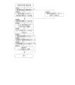
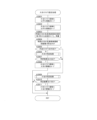
まず、メイン処理について説明する。図6A及び図6Bは、遊技制御装置100による
メイン処理の手順を示すフローチャートである。メイン処理は、電源が投入されることで
開始される。なお、遊技制御装置100が実行する処理のフローチャートにおいて、ステ
ップの符号(番号)は「A****」と表されている。
[Main processing (gaming control device)]
First, the main processing will be explained. FIG. 6A and FIG. 6B are flowcharts showing the procedure of main processing by the
図6Aに示すように、遊技制御装置100は、メイン処理を開始すると、まず、割込み
を禁止する処理を実行する(A1001)。さらに、割込み発生時にレジスタ等の値を退
避する領域の先頭アドレスであるスタックポインタを設定するスタックポインタ設定処理
を実行する(A1002)。
As shown in FIG. 6A, when the
続いて、使用するレジスタバンクとしてレジスタバンク0を指定し(A1003)、所
定のレジスタにRAM先頭アドレスの上位アドレスをセットする(A1004)。例えば
、RAMのアドレスが0000h~01FFhの範囲である場合に、上位アドレスとして
00hをセットする。
Next, register
次に、遊技制御装置100は、発射禁止の信号を出力して発射許可信号を禁止状態に設
定する(A1005)。発射許可信号は遊技制御装置100と払出制御装置200の少な
くとも一方が発射禁止の信号を出力している場合に禁止状態に設定され、遊技球の発射が
禁止されるようになっている。その後、遊技制御装置100は、設定キースイッチ93と
RAM初期化スイッチ112の状態を読み込む(A1006)。即ち、設定キースイッチ
93とRAM初期化スイッチ112からの信号を読み込む。
Next, the
さらに、遊技制御装置100は、電源ディレイタイマを設定する(A1007)。電源
ディレイタイマに所定の初期値を設定することにより、主制御手段をなす遊技制御装置1
00からの指示に従い種々の制御を行う従制御手段(例えば、払出制御装置200や演出
制御装置300)のプログラムが正常に起動するまで待機するための待機時間(例えば3
秒)が設定される。これにより、電源投入の際に仮に遊技制御装置100が先に立ち上が
って従制御装置(例えば払出制御装置200や演出制御装置300)が立ち上がる前にコ
マンドを従制御装置に送ってしまい、従制御装置がコマンドを取りこぼすことを回避する
ことができる。すなわち、遊技制御装置100が、電源投入時において、主制御手段(遊
技制御装置100)の起動を遅らせて従制御装置(払出制御装置200、演出制御装置3
00等)の起動を待つための所定の待機時間を設定する待機手段をなす。
Furthermore, the
A waiting time (for example, 3 seconds) for waiting until the program of the slave control means (for example, the
seconds) is set. As a result, when the power is turned on, if the
00, etc.) serves as a standby means for setting a predetermined standby time for waiting for activation.
また、電源ディレイタイマの計時は、RAMの正当性判定(チェックサム算出)の対象
とならない記憶領域(正当性判定対象外のRAM領域又はレジスタ等)を用いて行われる
。これにより、RAM領域のチェックサム等のチェックデータを算出する際に、一部のR
AM領域を除外して算出する必要がないため電源投入時の制御が複雑になることを防止す
ることができる。
Furthermore, the power supply delay timer is timed using a storage area that is not subject to RAM validity determination (checksum calculation) (such as a RAM area or register that is not subject to validity determination). As a result, when calculating check data such as checksum of the RAM area, some R
Since it is not necessary to perform calculations excluding the AM region, it is possible to prevent complicated control at power-on.
なお、待機時間の開始前に設定キースイッチ93とRAM初期化スイッチ112の状態
を読み込むことで、設定キースイッチ93とRAM初期化スイッチ112の操作を確実に
検出できる。すなわち、待機時間の経過後に設定キースイッチ93とRAM初期化スイッ
チ112の状態を読み込むようにすると、待機時間の経過を待ってから設定キースイッチ
93とRAM初期化スイッチ112を操作したり、電源投入から待機時間の経過まで設定
キースイッチ93とRAM初期化スイッチ112を操作し続けたりする必要がある。しか
し、待機時間の開始前に状態を読み込むことで、このような煩わしい操作を行わなくても
、電源投入時に行った設定キースイッチ93とRAM初期化スイッチ112の操作が受け
付けられないような事態を防止できる。
Note that by reading the states of the setting
電源ディレイタイマを設定すると(A1007)、遊技制御装置100は、待機時間の
計時と、待機時間中における停電の発生を監視する処理とを実行する(A1008からA
1010)。
When the power supply delay timer is set (A1007), the
1010).
停電監視処理が開始されると、遊技制御装置100は、まず、電源装置400から入力
されている停電監視信号をポート及びデータバスを介して読み込むなどして、停電が発生
しているか否か判定する(A1008)。停電が発生している場合に(A1008の結果
が「Y」)、遊技機の電源が遮断されるまで待機する。
When the power outage monitoring process is started, the
遊技制御装置100は、停電が発生していない場合には(A1008の結果が「N」)
、電源投入ディレイタイマを-1更新し(A1009)、タイマの値が0であるか否かを
判定する(A1010)。タイマの値が0でない場合(A1010の結果が「N」)、す
なわち、待機時間が終了していない場合には、ステップA1008の処理に戻る。
The
, updates the power-on delay timer by -1 (A1009), and determines whether the timer value is 0 (A1010). If the value of the timer is not 0 (the result of A1010 is "N"), that is, if the waiting time has not ended, the process returns to step A1008.
すなわち、遊技制御装置100が、所定の待機時間において停電の発生を監視する停電
監視手段をなす。これにより、主制御手段をなす遊技制御装置100の起動を遅らせてい
る期間において発生した停電に対応することが可能となり、電源投入時における不具合に
適切に対処することができる。なお、待機時間の終了まではRAMへのアクセスが許可さ
れておらず、前回の電源遮断時の記憶内容が保持されたままとなっているため、ここでの
停電発生時にはバックアップの処理等は行う必要がない。したがって、待機時間中に停電
が発生してもRAMのバックアップを取る必要がなく、制御の負担を軽減することができ
る。
That is, the
一方、遊技制御装置100は、タイマの値が0である場合(A1010の結果が「Y」
)、すなわち、待機時間が終了した場合には、RAMやEEPROM等の読出し書込み可
能なRWM(リードライトメモリ)のアクセスを許可し(A1011)、全出力ポートに
オフデータを出力(出力が無い状態に設定)する(A1012)。
On the other hand, if the timer value is 0 (the result of A1010 is "Y"), the
), that is, when the standby time has ended, access to readable and writable RWM (read/write memory) such as RAM and EEPROM is permitted (A1011), and off data is output to all output ports (no output state). ) (A1012).
次に、遊技制御装置100は、シリアルポート(遊技用マイコン111に予め搭載され
ているポートで、本実施形態では、演出制御装置300や払出制御装置200との通信に
使用)を設定する(A1013)。
Next, the
さらに、ここで、性能表示装置152(状態表示装置)を駆動するドライバ150を初
期設定してもよい。遊技制御装置100は、初期設定の内容に対応する制御用データを含
むコマンドを、第2出力ポート134(シリアル通信回路)の送信バッファに書き込んで
ドライバ150に送信する。例えば、遊技制御装置100は、初期設定においてデューテ
ィ比を設定する。デューティ比は、性能表示装置152の各LED(各セグメント)の明
るさに対応する。遊技制御装置100は、初期設定において、性能表示装置152の使用
桁数を設定する。本実施形態では、使用桁数は4である。
Furthermore, here, the
次に、遊技制御装置100は、遊技用マイコン111(クロックジェネレータ)内のタ
イマ割込み信号及び乱数更新トリガ信号(CTC)を発生するCTC(Counter/Timer C
ircuit)回路を起動する(A1014)。なお、CTC回路は、遊技用マイコン111内
のクロックジェネレータに設けられている。クロックジェネレータは、発振回路113か
らの発振信号(原クロック信号)を分周する分周回路と、分周された信号に基づいてCP
U111aに対して所定周期(例えば、4ミリ秒)のタイマ割込み信号及び乱数生成回路
に供給する乱数更新のトリガを与える信号CTCを発生するCTC回路とを備えている。
Next, the
(A1014). Note that the CTC circuit is provided in a clock generator within the
It is provided with a CTC circuit that generates a timer interrupt signal with a predetermined period (for example, 4 milliseconds) for U111a and a signal CTC that provides a trigger for updating a random number to be supplied to a random number generation circuit.
続いて、遊技制御装置100は、RAM(ここではRAM111c)の異常を示すRA
M異常フラグをセットする(A1015)。ここでは、一旦、異常前提のフラグを所定の
レジスタにセットしておく。
Subsequently, the
The M abnormality flag is set (A1015). Here, a flag assuming an abnormality is set in a predetermined register.
次に、遊技制御装置100は、RWM内の停電検査領域1の値が正常な停電検査領域チ
ェックデータであるか否かを判定する(A1016)。そして、正常であれば(A101
6の結果が「Y」)、RWM内の停電検査領域2の値が正常な停電検査領域チェックデー
タであるか否かを判定する(A1017)。
Next, the
6), it is determined whether the value of the power
さらに、遊技制御装置100は、停電検査領域2の値が正常であれば(A1017の結
果が「Y」)、RWM内の所定領域(例えば遊技制御用作業領域)のチェックサムを算出
するチェックサム算出処理を実行し(A1018)、算出されたチェックサムと電源断時
のチェックサムが一致するか否かを判定する(A1019)。チェックサムが一致する場
合には(A1019の結果が「Y」)、RAMは正常であり、RAMの異常を示すRAM
異常フラグをクリアする(A1020)。その後、ステップA1021の処理に移行する
。
Furthermore, if the value of the power
Clear the abnormality flag (A1020). Thereafter, the process moves to step A1021.
また、遊技制御装置100は、停電検査領域のチェックデータが正常なデータでないと
判定された場合(A1016の結果が「N」、又は、A1017の結果が「N」)、チェ
ックサムが一致しない場合には(A1019の結果が「N」)、RAM異常フラグをクリ
アすることなく、ステップA1021の処理に移行する。
In addition, the
次に、遊技制御装置100は、設定キースイッチ93及びRAM初期化スイッチ112
の両スイッチがオンであるか否かを判定する(A1021)。遊技制御装置100は、両
スイッチがオンである場合に(A1021の結果が「Y」)、設定可変状態(設定変更モ
ード)に移行し、ステップA1027-A1037の確率設定変更中の処理を実行する。
Next, the
It is determined whether both switches are on (A1021). When both switches are on (the result of A1021 is "Y"), the
遊技制御装置100は、設定キースイッチ93及びRAM初期化スイッチ112の少な
くとも一方がオフである場合に(A1021の結果が「N」)、RAM(ここではRAM
111c)の異常を示すRAM異常フラグがセットされているか否か判定する(A102
2)。RAM異常フラグがセットされていない場合に(A1022の結果が「N」)、確
率設定変更中フラグがセットされているか否かを判定する(A1023)。確率設定変更
中フラグがセットされていない場合に(A1023の結果が「N」)、ステップA103
1-A1037の確率設定確認中(設定確認状態中、設定確認モード中)の処理、ステッ
プA1041-1044のRAM初期化処理(RAMクリア処理)、又は、ステップA1
041、A1045、A1046の通常の電源投入時(電源復旧時)の処理を実行する。
When at least one of the setting
111c) is set (A102).
2). If the RAM abnormality flag is not set (the result of A1022 is "N"), it is determined whether the probability setting changing flag is set (A1023). If the probability setting changing flag is not set (result of A1023 is "N"), step A103
1-A1037 process during probability setting confirmation (in setting confirmation state, setting confirmation mode), RAM initialization process (RAM clear process) in steps A1041-1044, or step A1
041, A1045, and A1046, the normal power-on processing (power restoration time) is executed.
遊技制御装置100は、確率設定変更中フラグがセットされている場合に(A1023
の結果が「Y」)、遊技制御装置100(主基板、メイン基板)に異常があったことを報
知するメイン異常エラー報知のコマンドを演出制御装置300に送信する(A1024)
。メイン異常エラー報知のコマンドを受信した演出制御装置300は、遊技制御装置10
0の異常があったことを報知する。
When the probability setting changing flag is set, the
The result is "Y"), a main abnormality error notification command is sent to the
. The
Notify that 0 abnormalities have occurred.
続いて、遊技制御装置100は、遊技停止時の7セグ表示データ(図9(C)の「E1
」のエラー表示のデータ)を性能表示装置152で表示するために性能表示装置152の
ドライバ150に出力する(A1025)。そして、外部装置(遊技場内部管理装置(ホ
ールコンピュータ)や情報収集端末など)に異常を知らせるためのセキュリティ信号のオ
ンデータを外部情報端子71に出力する(A1026)。なお、ここで、大当りに関する
情報がRAM111cに残っている場合でも、大当り信号など外部情報端子71への他の
信号はオフ状態に維持される。その後、ステップA1025とA1026の処理を繰り返
して待機し、再度、設定変更の操作(設定キースイッチ93及びRAM初期化スイッチ1
12の両方のオン操作)をして電源が投入されるのを待つ。なお、ステップA1025と
A1026の処理を繰り返して待機して待機している間、割込みは禁止されたままであり
(A1001)、特図1、2ゲーム処理や普図ゲーム処理を実行可能なタイマ割込み処理
(図7)が実行できないため、遊技(特図変動表示ゲーム、普図変動表示ゲーム)は実行
できない。
Next, the
" error display data) is output to the
12) and wait for the power to be turned on. Note that while the processes of steps A1025 and A1026 are repeated and the process is on standby, interrupts remain prohibited (A1001), and the timer interrupt processing that can execute the
このように、設定変更の操作(設定キースイッチ93及びRAM初期化スイッチ112
の両方のオン操作)を実行していないのに、確率設定変更中フラグがセットされている場
合に異常があったとして、A1024-A1026の処理を実行する。例えば、確率設定
変更中(設定変更が完了する前)に電源がオフして再起動した場合などに、設定変更の操
作を実行していないのに、確率設定変更中フラグがセットされることがある。
In this way, the settings change operation (setting
If the probability setting changing flag is set even though both of the on operations (on operations) have not been executed, it is assumed that an abnormality has occurred and the processes A1024 to A1026 are executed. For example, if the power is turned off and restarted while the probability setting is being changed (before the setting change is completed), the probability setting changing flag may be set even though the setting change operation has not been performed. be.
一方、遊技制御装置100は、RAM異常フラグがセットされている場合も(A102
2の結果が「Y」)、遊技制御装置100(メイン基板)に異常があったことを報知する
メイン異常エラー報知のコマンドを演出制御装置300に送信し(A1024)、遊技停
止時の7セグ表示データ(図9(C)の「E1」のエラー表示のデータ)を性能表示装置
152のドライバ150に出力し(A1025)、外部装置にRAM異常を知らせるため
に、セキュリティ信号のオンデータを外部情報端子71に出力する(A1026)。なお
、前述と同様に、大当りに関する情報がRAM111cに残っている場合でも、大当り信
号など外部情報端子71への他の信号はオフ状態に維持される。その後、ステップA10
25とA1026の処理を繰り返して待機する。
On the other hand, even when the RAM abnormality flag is set (A102
2 result is "Y"), a main abnormality error notification command is sent to the
25 and A1026 are repeated and the process waits.
遊技制御装置100は、設定キースイッチ93及びRAM初期化スイッチ112の両ス
イッチがオンである場合に(A1021の結果が「Y」)、確率設定変更中(設定可変状
態中)の処理を開始して、まず、RAM異常フラグがセットされているか否かを判定する
(A1027)。RAM異常フラグがセットされている場合に(A1027の結果が「Y
」)、確率設定値が正しいものであるか不明であるため、RAM111cの確率設定値領
域に記憶されている確率設定値をクリアし初期値(例えば最低設定値「1」)にしてから
(A1028)、確率設定変更中であることを示す確率設定変更中フラグをセットする(
A1029)。RAM異常フラグがセットされていない場合に(A1027の結果が「N
」)、確率設定値をクリアせずに、確率設定変更中フラグをセットする(A1029)。
次に、確率設定変更中のコマンドを演出制御装置300(演出制御基板)に送信し(A1
030)、ステップA1034の処理に移行する。なお、確率設定変更中のコマンドを受
信した演出制御装置300は、確率設定変更中であることを表示装置41などにおいて報
知する。
When both the setting
), it is unclear whether the probability setting value is correct or not, so clear the probability setting value stored in the probability setting value area of the
A1029). If the RAM error flag is not set (A1027 result is “N
"), the probability setting changing flag is set without clearing the probability setting value (A1029).
Next, a command for changing the probability setting is sent to the production control device 300 (production control board) (A1
030), the process moves to step A1034. In addition, the
遊技制御装置100は、設定キースイッチ93及びRAM初期化スイッチ112の少な
くとも一方がオフであり(A1021の結果が「N」)、RAM異常フラグがセットされ
ておらず(A1022の結果が「N」)、且つ、確率設定変更中フラグがセットされてい
ない場合に(A1023の結果が「N」)、設定キースイッチ93がオンであるか否かを
判定する(A1031)。設定キースイッチ93がオンである場合に(A1031の結果
が「Y」)、RAM初期化スイッチ112はオフということになり、確率設定確認中(設
定確認状態中)の処理が開始して、確率設定確認中であることを示す確率設定確認中フラ
グをセットする(A1032)。そして、確率設定確認中のコマンドを演出制御装置30
0(演出制御基板)に送信し(A1033)、ステップA1034の処理に移行する。な
お、確率設定変更中のコマンドを受信した演出制御装置300は、確率設定確認中である
ことを表示装置41などにおいて報知する。
In the
0 (effect control board) (A1033), and the process moves to step A1034. In addition, the
ステップA1030又はステップA1033の後に、遊技制御装置100は、確率設定
変更中と確率設定確認中の共通の処理として、ステップA1034からA1040の処理
を実行する。
After step A1030 or step A1033, the
遊技制御装置100は、まず、確率設定変更中と確率設定確認中においてセキュリティ
信号を出力するために、セキュリティ信号制御タイマ領域に128ms(所定時間)をセ
ーブする(A1034)。なお、セキュリティ信号制御タイマのカウントとセキュリティ
信号の出力は、後述の確率設定変更/確認処理(図8)において実行されるが、確率設定
変更又は確率設定確認が早期に終了した場合には、残りのセキュリティ信号制御タイマの
カウントとセキュリティ信号の出力は、外部情報編集処理(A1321)で実行される。
確率設定変更中と確率設定確認中において、少なくとも50msは、セキュリティ信号は
出力される。
The
The security signal is output for at least 50 ms during probability setting change and probability setting confirmation.
次に、遊技制御装置100は、割込みを許可する(A1035)。これにより、タイマ
割込み処理(図7)が実行可能となる。そして、設定キースイッチ93がオフであるか否
かを判定する(A1036)。設定キースイッチ93がオンである場合に(A1036の
結果が「N」)、停電が発生しているか否かを判定する(A1037)。停電が発生して
いない場合に(A1037の結果が「N」)、ステップA1036の処理に戻る。一方、
停電が発生している場合に(A1037の結果が「Y」)、ステップA1055-A10
61の停電発生時の処理を実行する。
Next, the
If a power outage has occurred (the result of A1037 is "Y"), steps A1055-A10
61 is executed when a power outage occurs.
このように、設定キースイッチ93がオンであり、停電が発生していない限り、確率設
定値を変更可能な設定可変状態(設定変更状態、設定変更モード)、又は、確率設定値を
確認可能な設定確認状態(設定確認モード)が継続される。
In this way, as long as the setting
一方、遊技制御装置100は、設定キースイッチ93がオフである場合に(A1036
の結果が「Y」)、割込みを禁止し(A1038)、報知終了のコマンドを演出制御装置
300(演出制御基板)に送信する(A1039)。なお、報知終了のコマンドを受信し
た演出制御装置300は、確率設定確認中であることの報知又は確率設定変更中であるこ
との報知を終了する。
On the other hand, when the setting
The result is "Y"), interrupts are prohibited (A1038), and a command to end the notification is sent to the production control device 300 (production control board) (A1039). In addition, the
次に、遊技制御装置100は、確率設定変更中フラグがセットされているか否か、即ち
、これまで確率設定変更中であったか否かを判定する(A1040)。確率設定変更中フ
ラグがセットされている場合に(A1040の結果が「Y」)、即ち、これまで確率設定
変更中であった場合に、ステップA1042-A1044のRAM初期化処理(後述)を
実行する。一方、確率設定変更中フラグがセットされていない場合に(A1040の結果
が「N」)、即ち、これまで確率設定確認中であった場合に、ステップA1045以降の
電源投入時(電源復旧時)の通常の処理を実行する。
Next, the
遊技制御装置100は、設定キースイッチ93がオフである場合に(A1031の結果
が「N」)、RAM初期化スイッチ112がオンであるか否かを判定する(A1041)
。RAM初期化スイッチ112がオンである場合に(A1041の結果が「Y」)、RA
M111cにおいて、確率設定値を記憶するための確率設定値領域以外のRAM領域を0
クリアする(A1042)。即ち、確率設定値領域で記憶されている確率設定値を除いて
、RAM111cに記憶された遊技情報は0クリアされる。さらに、前述の確率設定変更
中フラグもここでクリアされる。また、ここで、確率設定値領域の他に、スタック領域や
未使用領域をクリアしない構成や、性能情報やその表示(性能表示)に関連するワークエ
リア、スタック領域をクリアしない構成も可能である。なお、性能情報は、入賞により得
られた賞球数に基づいて導出されるもので、例えば、出玉率、ベース値(通常遊技状態に
おける出玉率)、役物比率、排出球数などである。
When the setting
. When the
In M111c, the RAM area other than the probability setting value area for storing probability setting values is set to 0.
Clear (A1042). That is, the game information stored in the
次に、遊技制御装置100は、初期化すべき領域にRAM初期化時の初期値をセーブす
る(A1043)。そして、RAM初期化時のコマンドを演出制御装置300(演出制御
基板)に送信し(A1044)、ステップA1047の処理に移行する。
Next, the
一方、遊技制御装置100は、RAM初期化スイッチ112がオフである場合に(A1
041の結果が「N」)、設定キースイッチ93とRAM初期化スイッチ112が両方と
もオフであるため、通常の電源投入時(電源復旧時)の処理を開始し、停電復旧処理を実
行する(A1045)。例えば、初期化すべき領域に停電復旧時(復電時)の初期値をセ
ーブする。また、前述の確率設定確認中フラグもここでクリアされる。次に、後述の特図
ゲーム処理を合理的に実行するために用意されている処理番号に対応する停電復旧時のコ
マンドを演出制御装置300(演出制御基板)に送信し(A1046)、ステップA10
47の処理に移行する。
On the other hand, when the
041 result is "N"), and the setting
The process moves to step 47.
なお、ステップA1044の処理で送信されるRAM初期化時のコマンド及びステップ
A1046の処理で送信される停電復旧時のコマンドには、遊技機の種類を示す機種指定
コマンド、特図1、2の保留数を示す飾り特図1保留数コマンド及び飾り特図2保留数コ
マンド、確率の状態(高確率状態又は低確率状態)や時短状態の有無を示す確率情報コマ
ンド、所定の演出モードで特図変動表示ゲームが実行された回数を示す演出回数情報コマ
ンド、電源投入されたこと示す停電復旧コマンドが含まれる。
Note that the RAM initialization command sent in the process of step A1044 and the power failure recovery command sent in the process of step A1046 include a model designation command indicating the type of gaming machine, and a reservation for
さらに、RAM初期化時のコマンド及び停電復旧時のコマンドには、遊技機10の確率
設定値(設定値)の情報である設定値情報を示す設定値情報コマンド(確率設定値情報コ
マンド)が含まれる。遊技制御装置100は、電源の復旧(投入)時に、一度だけ設定値
情報コマンドを演出制御装置300に送信するだけでよく、以降、演出制御装置300は
自身が記憶した設定値情報を参照して演出制御を行える。
Furthermore, the commands at the time of RAM initialization and the commands at the time of power restoration include a setting value information command (probability setting value information command) indicating setting value information that is information on the probability setting value (setting value) of the
なお、RAM初期化時のコマンドには、RAM初期化のコマンド(RAMクリアのコマ
ンド)も含まれる。RAM初期化のコマンドを受信した演出制御装置300は、例えば、
表示装置41に客待ちデモを表示し、盤装飾装置46等のLEDとスピーカの音でRAM
初期化(RAMクリア)の報知を30秒間行う。また、停電復旧時のコマンドには、表示
装置41の画面の表示内容を指定する画面指定のコマンドが含まれる。なお、画面指定の
コマンドは、特図1、2について共に普段処理中では(変動中でも当り中でもないとき)
、客待ちデモコマンドであり、それ以外なら復旧画面コマンドである。
Note that the RAM initialization commands also include a RAM initialization command (RAM clear command). The
A customer waiting demonstration is displayed on the
Initialization (RAM clear) will be notified for 30 seconds. Further, the commands at the time of power restoration include a screen designation command that designates the display contents of the screen of the
, is a customer waiting demo command, and otherwise is a recovery screen command.
ステップA1044又はステップA1046の後に、遊技制御装置100は、乱数生成
回路を起動設定する(A1047)。具体的には、乱数生成回路内の所定のレジスタ(C
TC更新許可レジスタ)に乱数生成回路を起動させるためのコード(指定値)の設定など
がCPU111aによって行われる。また、乱数生成回路のハードウェアで生成されるハ
ード乱数(ここでは大当り乱数)のビット転置パターンの設定も行われる。
After step A1044 or step A1046, the
The
ビット転置パターンとは、抽出した乱数のビット配置(上段のビット転置前の配置)を
、予め定められた順で入れ替えて異なるビット配置(下段のビット転置後の配置)として
格納する際の入れ替え方を定めるパターンである。
A bit transposition pattern is a method of replacing the bit arrangement of extracted random numbers (the arrangement before bit transposition in the upper row) in a predetermined order and storing it as a different bit arrangement (the arrangement after bit transposition in the lower row). This is the pattern that defines the
本実施形態では、ビット転置パターンに従い乱数のビットを入れ替えることで、乱数の
規則性を崩すことができるとともに、乱数の秘匿性を高めることができる。なお、ビット
転置パターンは、固定された単一のパターンであってもよいし、予め用意された複数のパ
ターンから選択するようにしてもよい。また、ユーザーが任意に設定できるようにしても
よい。
In this embodiment, by replacing the bits of the random number according to the bit transposition pattern, the regularity of the random number can be broken, and the secrecy of the random number can be improved. Note that the bit transposition pattern may be a single fixed pattern, or may be selected from a plurality of patterns prepared in advance. Alternatively, the user may be able to set it arbitrarily.
その後、遊技制御装置100は、電源投入時の乱数生成回路内の所定のレジスタ(ソフ
ト乱数レジスタ1~n)の値を抽出し、対応する各種初期値乱数(大当り図柄を決定する
大当り図柄乱数の初期値(大当り図柄初期値乱数)、小当り図柄を決定する小当り図柄乱
数の初期値(小当り図柄初期値乱数)、普図の当りを決定する当り乱数の初期値(当り初
期値乱数)、転落抽選で使用する転落抽選乱数の初期値(転落抽選初期値乱数)等)のス
タート値としてRWMの所定領域にセーブし(A1048)、割込みを許可する(A10
49)。本実施形態で使用するCPU111a内の乱数生成回路においては、電源投入ご
とにソフト乱数レジスタの初期値が変わるように構成されているため、この値を各種初期
値乱数のスタート値(初期値)とすることで、ソフトウェアで生成される乱数の規則性を
崩すことができ、遊技者による不正な乱数の取得を困難にすることができる。
After that, the
49). The random number generation circuit in the
続いて、遊技制御装置100は、各種初期値乱数の値を更新して乱数の規則性を崩すた
めの初期値乱数更新処理を実行する(A1050)。なお、特に限定されるわけではない
が、本実施形態においては、大当り乱数、大当り図柄乱数、当り乱数、転落抽選乱数は乱
数生成回路において生成される乱数を使用して生成するように構成されている。ただし、
大当り乱数はCPUの動作クロックと同等以上の速度のクロックを基にして更新される所
謂「高速カウンタ」であり、大当り図柄乱数、当り乱数、転落抽選乱数はプログラムの処
理単位であるタイマ割込み処理と同周期となるCTC出力(タイマ割込み処理のCTC(
CTC0)とは別のCTC(CTC2))を基にして更新される「低速カウンタ」である
。
Subsequently, the
The jackpot random number is a so-called "high-speed counter" that is updated based on a clock with a speed equal to or faster than the CPU operating clock, and the jackpot symbol random number, winning random number, and falling lottery random number are processed by timer interrupt processing, which is the processing unit of the program. CTC output with the same cycle (CTC of timer interrupt processing (
This is a "low speed counter" that is updated based on a CTC (CTC2)) that is different from CTC0).
また、大当り図柄乱数、当り図柄乱数、転落抽選乱数においては、乱数が一巡するごと
に各々の初期値乱数(ソフトウェアで生成)を用いてスタート値を変更する所謂「初期値
変更方式」を採用している。なお、前記各乱数は、+1あるいは1によるカウンタ式更新
でもよいし、一巡するまで範囲内のすべての値が重複なくバラバラに出現するランダム式
更新でもよい。つまり、大当り乱数はハードウェアのみで更新される乱数であり、大当り
図柄乱数、当り乱数、転落抽選乱数はハードウェア及びソフトウェアで更新される乱数で
ある。
In addition, for jackpot pattern random numbers, winning pattern random numbers, and falling lottery random numbers, we adopt the so-called "initial value change method" in which the starting value is changed using each initial value random number (generated by software) every time the random numbers go around. ing. Note that each of the random numbers may be updated using a counter method such as +1 or 1, or may be updated using a random method in which all values within the range appear randomly without duplication until one cycle is completed. That is, the jackpot random number is a random number that is updated only by hardware, and the jackpot symbol random number, hit random number, and fall lottery random number are random numbers that are updated by hardware and software.
続いて、遊技制御装置100は、割込みを禁止し(A1051)、性能情報やその表示
(性能表示)を編集する性能表示編集処理を実行する(A1052)。ここで、性能情報
(役物比率や出玉率など)を計算してよい。また、RAM異常フラグがレジスタにセット
されていた場合に、性能情報やその表示(性能表示)に関連するワークエリア、スタック
領域をクリアしてもよい(ステップA1042でクリアされていないなら)。その後、割
込みを許可する(A1053)。これにより、タイマ割込み処理(図7)が実行可能とな
る。
Subsequently, the
次に、遊技制御装置100は、停電が発生しているか否かを判定する(A1054)。
停電が発生していない場合に(A1054の結果が「N」)、ステップA1050の処理
に戻る。これにより、停電が発生するまで、ステップA1050-A1054の処理が繰
り返される。
Next, the
If a power outage has not occurred (the result of A1054 is "N"), the process returns to step A1050. As a result, the processes of steps A1050 to A1054 are repeated until a power outage occurs.
停電が発生した場合に(A1054の結果が「Y」)、遊技制御装置100は、停電発
生時の処理を開始し、一旦割込みを禁止し(A1055)、全出力ポートにオフデータを
出力する(1056)。その後、停電検査領域1に停電検査領域チェックデータ1をセー
ブし(A1057)、停電検査領域2に停電検査領域チェックデータ2をセーブする(A
1058)。さらに、RWMの電源遮断時のチェックサムを算出するチェックサム算出処
理を実行し(A1059)、さらに、算出したチェックサムをセーブする(A1060)
。最後に、RWMへのアクセスを禁止する処理を実行し(A1061)、遊技機の電源が
遮断されるまで待機する。
When a power outage occurs (result of A1054 is "Y"), the
1058). Furthermore, a checksum calculation process is executed to calculate the checksum when the RWM power is turned off (A1059), and the calculated checksum is saved (A1060).
. Finally, processing is executed to prohibit access to the RWM (A1061), and the game machine waits until the power is turned off.
このように、停電検査領域にチェックデータをセーブするとともに、電源遮断時のチェ
ックサムを算出することで、電源の遮断の前にRWMに記憶されていた情報が正しくバッ
クアップされているか否かを電源再投入時に判断することができる。
In this way, by saving the check data in the power failure inspection area and calculating the checksum at the time of power failure, it is possible to check whether the information stored in the RWM before power failure has been correctly backed up. This can be determined at the time of reinsertion.
〔タイマ割込み処理〕
次に、タイマ割込み処理について説明する。図7は、タイマ割込み処理(割込み処理プ
ログラム)の手順を示すフローチャートである。タイマ割込み処理は、クロックジェネレ
ータ内のCTC回路で生成される周期的なタイマ割込み信号がCPU111aに入力され
ることで開始される。遊技用マイコン111においてタイマ割込みが発生すると、タイマ
割込み処理が開始される。
[Timer interrupt processing]
Next, timer interrupt processing will be explained. FIG. 7 is a flowchart showing the procedure of timer interrupt processing (interrupt processing program). The timer interrupt process is started when a periodic timer interrupt signal generated by a CTC circuit in the clock generator is input to the
タイマ割込み処理が開始されると、遊技制御装置100は、まず、使用するレジスタバ
ンクとしてレジスタバンク1を指定し(A1301)、所定のレジスタにRAM先頭アド
レスの上位アドレスをセットする(A1302)。タイマ割込み処理の開始時にメイン処
理で使用するレジスタバンク0からレジスタバンク1に切り替えることで、メイン処理で
使っているレジスタを退避したのと同等になる。なお、タイマ割込み処理が開始されると
、自動的に割込み禁止状態になる。
When the timer interrupt process is started, the
次に、遊技制御装置100は、各種センサやスイッチからの入力や、信号の取り込み、
すなわち、各入力ポートの状態を読み込む入力処理を実行する(A1303)。次に、確
率設定変更中フラグと確率設定確認中フラグに基づいて、確率設定変更中又は確率設定確
認中であるか否かを判定する(A1304)。確率設定変更中又は確率設定確認中である
場合に(A1304の結果が「Y」)、確率設定値を変更又は確認するための確率設定変
更/確認処理を実行する(A1305)。
Next, the
That is, input processing for reading the status of each input port is executed (A1303). Next, based on the probability setting changing flag and the probability setting confirmation flag, it is determined whether the probability setting is being changed or the probability setting is being confirmed (A1304). If the probability setting is being changed or the probability setting is being confirmed (the result of A1304 is "Y"), a probability setting change/confirmation process is executed to change or confirm the probability setting value (A1305).
遊技制御装置100は、確率設定変更中でも確率設定確認中でもない場合に(A130
4の結果が「N」)、各種処理でセットされた出力データに基づき、ソレノイド(大入賞
口ソレノイド38b,39b)等のアクチュエータの駆動制御などを行うための出力処理
を実行する(A1306)。なお、メイン処理におけるステップA1005の処理で発射
禁止の信号を出力した場合は、この出力処理が行われることで発射許可の信号が出力され
、発射許可信号を許可状態に設定可能な状態とする。
When the
4), based on the output data set in various processes, output processing is executed to perform drive control of actuators such as solenoids (big winning
次に、遊技制御装置100は、各種処理で送信バッファにセットされたコマンドを払出
制御装置200に出力する払出コマンド送信処理を実行し(A1307)、さらに、乱数
更新処理1(A1308)、乱数更新処理2(A1309)を実行する。その後、始動口
1スイッチ36a、始動口2スイッチ37a、入賞口スイッチ35a、下大入賞口スイッ
チ38a、上大入賞口スイッチ39aから正常な信号の入力があるか否かの監視や、エラ
ーの監視(前面枠やガラス枠が開放されていないかなど)を行う入賞口スイッチ/状態監
視処理を実行する(A1310)。
Next, the
次に、遊技制御装置100は、大入賞口で遊技球の異常排出が発生中であるか否かを判
定する(A1311)。後述の異常排出監視処理(A1320)によって異常排出発生中
フラグが設定された場合に、異常排出が発生中であると判定できる。異常排出が発生中で
ある場合に(A1311の結果が「Y」)、ステップA1317以降の処理を実行する。
Next, the
遊技制御装置100は、異常排出が発生中でない場合に(A1311の結果が「N」)
、始動口1スイッチ36a及び始動口2スイッチ37aにより始動口への入賞を監視する
始動口スイッチ監視処理を実行する(A1312)。続いて、特図1変動表示ゲームに関
する処理を行う特図1ゲーム処理を実行し(A1313)、次に、特図2変動表示ゲーム
に関する処理を行う特図2ゲーム処理を実行する(A1314)。なお、特図1ゲーム処
理と特図2ゲーム処理の詳細については後述する。
The
, A starting port switch monitoring process is executed to monitor winnings in the starting port using the starting
次に、遊技制御装置100は、普図変動表示ゲームに関する処理を行う普図ゲーム処理
を実行する(A1315)。遊技機10に設けられ、特図変動ゲームの表示や遊技に関す
る各種情報を表示するセグメントLEDを所望の内容を表示するように駆動するセグメン
トLED編集処理を実行する(A1316)。
Next, the
さらに、遊技制御装置100は、磁気センサスイッチ61からの検出信号をチェックし
て異常がないか否かを判定する磁石不正監視処理を実行する(A1317)。さらに、遊
技盤の電波センサ62からの検出信号をチェックして異常がないか否かを判定する電波不
正監視処理(盤電波不正監視処理)を実行する(A1318)。
Furthermore, the
その後、遊技制御装置100は、振動センサ65からの入力に基づいて振動による不正
を監視する振動不正監視処理を実行する(A1319)。次に、大入賞口からの異常排出
を監視する異常排出監視処理を実行する(A1320)。異常排出監視処理では、特別変
動入賞装置38、39における大入賞口スイッチ43(下大入賞口スイッチ38a、上大
入賞口スイッチ39a)、特定領域スイッチ72(V入賞口スイッチ)、残存球排出口ス
イッチ73からの入力に基づいて、特別変動入賞装置38、39の異常排出を監視し、異
常排出が発生した場合に異常排出発生中フラグが設定される。なお、特別変動入賞装置3
8、39の大入賞口スイッチ43を通過した遊技球は、特定領域スイッチ72(V入賞口
スイッチ)又は残存球排出口スイッチ73を通過して排出される。
After that, the
The game balls that have passed through the big winning
次に、遊技制御装置100は、各種外部装置に出力する信号を出力バッファにセットす
る外部情報編集処理を実行する(A1321)。そして、性能表示装置152の表示を制
御する性能表示モニタ制御処理を実行する(A1322)。その後、タイマ割込み処理を
終了する。
Next, the
なお、タイマ割込み処理のリターンの際、割込み禁止状態の復元やレジスタバンクの指
定の復元は、自動的に行われる構成とするが、使用するCPUによっては、外部情報編集
処理の後に、割込みを許可する処理やレジスタバンクの指定をレジスタバンク0に戻す処
理を行ってもよい。
Note that when timer interrupt processing returns, the interrupt disabled state and register bank specification are automatically restored, but depending on the CPU used, interrupts may be enabled after external information editing processing. It is also possible to perform processing to return the register bank designation to register
〔確率設定変更/確認処理〕
次に、タイマ割込み処理における確率設定変更/確認処理(A1305)の詳細につい
て説明する。図8は、確率設定変更/確認処理の手順を示すフローチャートである。確率
設定変更/確認処理では、確率設定値が変更又は確認できる。
[Probability setting change/confirmation process]
Next, details of the probability setting change/confirmation process (A1305) in the timer interrupt process will be described. FIG. 8 is a flowchart showing the procedure of probability setting change/confirmation processing. In the probability setting change/confirmation process, the probability setting value can be changed or confirmed.
遊技制御装置100は、まず、確率設定値が正常範囲内であるか否かを判定する(A2
401)。ここでの確率設定値は、RAM111cの確率設定値領域に記憶されている。
The
401). The probability setting value here is stored in the probability setting value area of the
遊技制御装置100は、確率設定値が正常範囲内である場合に(A2401の結果が「
Y」)、確率設定値に対応する確率設定値表示データを設定して(A2402)、性能表
示装置152にドライバ150を介して出力する(A2404)。確率設定値が正常範囲
内でない場合に(A2401の結果が「N」)、確率設定値表示データとして消灯データ
を設定して(A2403)、性能表示装置152にドライバ150を介して出力する(A
2404)。
The
Y''), sets probability setting value display data corresponding to the probability setting value (A2402), and outputs it to the
2404).
ここで、確率設定値表示データは、性能表示装置152で表示される表示用確率設定値
のデータであり、確率設定値表示データ領域に記憶されている。なお、ホール関係者等の
混乱を防止するため、確率設定値が異なっても同じ大当り確率(及び小当たり確率)であ
れば、表示用確率設定値を大当り確率(及び小当たり確率)に対応付けて同じにしてよい
。即ち、同じ表示用確率設定値は、同じ大当り確率(及び小当たり確率)を意味してよい
。
Here, the probability setting value display data is data of the probability setting value for display displayed on the
次に、遊技制御装置100は、セキュリティ信号制御タイマが0でなければ-1更新す
る(A2405)。セキュリティ信号制御タイマは、ステップA1034で設定された1
28ms(所定時間)である。続いて、外部装置(遊技場内部管理装置(ホールコンピュ
ータ)など)に異常を知らせるためのセキュリティ信号のオンデータを外部情報端子71
に出力する(A1026)。なお、ここで、大当り信号など外部情報端子71への他の信
号はオフ状態に維持される。
Next, the
It is 28ms (predetermined time). Next, the on-data of the security signal is sent to the
(A1026). Note that at this point, other signals such as the jackpot signal to the
その後、遊技制御装置100は、確率設定変更中フラグがセットされているか否かを判
定する(A2407)。確率設定変更中フラグがセットされていない場合に(A2407
の結果が「N」)、即ち、確率設定確認中である場合に、何もせずに確率設定変更/確認
処理を終了する。
After that, the
If the result is "N"), that is, the probability setting is being confirmed, the probability setting change/confirmation process is ended without doing anything.
遊技制御装置100は、確率設定変更中フラグがセットされている場合に(A2407
の結果が「Y」)、即ち、確率設定変更中である場合に、電源投入後の最初のタイマ割込
み処理であるか否かを判定する(A2408)。電源投入後の最初のタイマ割込み処理で
ある場合に(A2408の結果が「Y」)、確率設定変更/確認処理を終了する。これは
、RAM初期化スイッチ112を押しっぱなしだった場合に、意図せずに確率設定値の更
新がされる事態を防止するためである。
When the probability setting changing flag is set, the
If the result is "Y"), that is, the probability setting is being changed, it is determined whether or not this is the first timer interrupt process after the power is turned on (A2408). If this is the first timer interrupt process after the power is turned on (the result of A2408 is "Y"), the probability setting change/confirmation process ends. This is to prevent the probability setting value from being updated unintentionally if the
遊技制御装置100は、電源投入後の最初のタイマ割込み処理でない場合に(A240
8の結果が「N」)、RAM初期化スイッチ112の入力があるか否かを判定する(A2
409)。RAM初期化スイッチの入力がない場合に(A2409の結果が「N」)、確
率設定変更/確認処理を終了する。
When the
8), it is determined whether there is an input to the RAM initialization switch 112 (A2
409). If there is no input to the RAM initialization switch (the result of A2409 is "N"), the probability setting change/confirmation process ends.
遊技制御装置100は、RAM初期化スイッチ112の入力がある場合に(A2409
の結果が「Y」)、作業用設定値領域(RAM111c内又はレジスタ)の作業用設定値
を0~5の範囲で+1更新するとともに、作業用設定値に対応して確率設定値領域の確率
設定値1~6を+1更新する(A2410)。これにより、RAM初期化スイッチ112
が操作される度に、確率設定値領域の確率設定値が1ずつ更新される。その後、確率設定
変更/確認処理を終了する。なお、設定変更モードに入ったときに作業用設定値を格納す
る作業用設定値領域(RAM111c内又はレジスタ)に、確率設定値領域から読み出し
た確率設定値に対応する値(確率設定値から1減算した値)が格納されてよい。
When the
result is "Y"), the working setting value in the working setting value area (
Each time is operated, the probability setting value in the probability setting value area is updated by one. Thereafter, the probability setting change/confirmation process ends. Note that when entering the setting change mode, a value corresponding to the probability setting value read from the probability setting value area (1 from the probability setting value subtracted value) may be stored.
なお、上記では、RAM初期化スイッチ112が操作される度に、作業用設定値の更新
に対応して確率設定値領域の確率設定値を直接更新するようにしたが、RAM111cの
作業用設定値領域に設定変更中の確率設定値(作業用設定値)を記憶するようにし、設定
キースイッチ93がオフになり設定変更作業が完了したときに(A1036の結果が「Y
」)、作業用設定値領域の作業用設定値に対応する値をはじめて確率設定値領域に格納す
るようにしてもよい。このようにすれば、設定変更中に停電が発生した場合(A1037
の結果が「Y」)に、遊技制御や演出制御等に使用される確率設定値(確率設定値領域に
記憶される確率設定値)が意図しない値で変更される事態を防止できる。
In the above, the probability setting value in the probability setting value area is directly updated in response to the update of the working setting value every time the
''), the value corresponding to the working setting value in the working setting value area may be stored in the probability setting value area for the first time. In this way, if a power outage occurs while changing settings (A1037
If the result is "Y"), it is possible to prevent a situation in which the probability setting value (probability setting value stored in the probability setting value area) used for game control, production control, etc. is changed to an unintended value.
〔性能表示装置での表示例〕
図9は、性能表示装置152の表示例を示す図である。性能表示装置152は、4桁の
7セグメント型(ドットDpを含めると8セグメント型)の表示器であるが、性能表示装
置152の各桁は、8セグメントa,b,c,d,e,f,g,Dpからなる。
[Example of display on performance display device]
FIG. 9 is a diagram showing a display example of the
図9(a)の例において、確率設定変更中において、桁1から桁3に、設定変更中であ
ることを示すため「SET」という点灯表示がされている。一方、確率設定変更中にRA
M初期化スイッチ112が操作される度に切り替わる作業用設定値0~5に対応して、桁
0では、表示用確率設定値が例えば「1」~「6」に切り替わって点灯表示される。
In the example of FIG. 9(a), while the probability setting is being changed,
Corresponding to the
図9(b)の例において、確率設定値が正常範囲内でなく異常な場合に(A2401の
結果が「N」)、確率設定値表示データとして消灯データを設定して(A2403)、桁
0が消灯する。なお、桁1から桁3において、設定変更中であることを示す「SET」の
表示は、消灯されない。
In the example of FIG. 9(b), when the probability setting value is not within the normal range and is abnormal (the result of A2401 is "N"), the off data is set as the probability setting value display data (A2403), and the
図9(c)の例において、電源投入時にRAMが異常の場合(A1022の結果が「Y
」)や、確率設定変更中(設定変更が完了する前)に電源がオフして再起動した場合(A
1023の結果が「Y」)に、遊技停止時の7セグ表示データエラー表示「E1」が桁1
、2で点灯表示されている(A1024)。
In the example of FIG. 9(c), if the RAM is abnormal when the power is turned on (the result of A1022 is "Y
), or if the power is turned off and restarted while changing the probability setting (before the setting change is complete) (A
The result of 1023 is "Y"), and the 7-segment display data error display "E1" when the game is stopped is
, 2 is lit and displayed (A1024).
〔始動口スイッチ監視処理〕
次に、前述のタイマ割込み処理における始動口スイッチ監視処理(A1312)の詳細
について説明する。図10は、始動口スイッチ監視処理の手順を示すフローチャートであ
る。
[Start switch monitoring process]
Next, details of the start port switch monitoring process (A1312) in the above-mentioned timer interrupt process will be explained. FIG. 10 is a flowchart showing the procedure of the starting port switch monitoring process.
遊技制御装置100は、まず、第1始動入賞口36(始動口1)への入賞を監視する始
動口1入賞監視テーブルを準備し(A2701)、大当り乱数としてハード乱数を取得す
るハード乱数取得処理を実行する(A2702)。次に、第1始動入賞口36への始動口
入賞があったか否かを判定する(A2703)。そして、始動口入賞がなかった場合(A
2703の結果が「N」)、ステップA2709の処理に移行する。
The
If the result of step A2703 is "N"), the process moves to step A2709.
遊技制御装置100は、第1始動入賞口36への始動口入賞があった場合(A2703
の結果が「Y」)、大当りの発生確率が低確率状態であり且つ時短なしの状態(普電サポ
ートなしの状態)であるか否か、即ち、特図低確率&時短なし中(通常遊技状態中)であ
るか否かを判定する(A2704)。特図ゲームモードフラグ領域に特図低確率&時短な
しフラグが設定されていれば、特図低確率&時短なし中(通常遊技状態中)であると判定
できる。そして、低確率状態且つ時短なしの状態である場合(A2704の結果が「Y」
)、即ち通常遊技状態である場合、ステップA2707の処理に移行する。
The
The result is "Y"), the probability of occurrence of jackpot is low probability state and no time saving state (state without public power support). (A2704). If the special figure low probability & no time saving flag is set in the special figure game mode flag area, it can be determined that the special figure low probability & no time saving is in progress (normal game state). If it is a low probability state and no time saving state (the result of A2704 is "Y")
), that is, in the normal gaming state, the process moves to step A2707.
遊技制御装置100は、大当りの発生確率が低確率状態でない場合(高確率状態である
場合)又は時短ありの状態(普電サポートありの状態)である場合(A2704の結果が
「N」)、演出コマンドとして右打ち指示報知コマンドを準備し(A2705)、演出コ
マンド設定処理を実行する(A2706)。これにより、演出制御装置300は、特図高
確率状態又は時短状態で第1始動入賞口36への始動口入賞があった場合に、右打ちを指
示する右打ち指示表示を警告として表示装置41に表示することができる。なお、演出コ
マンド設定処理では、シリアル送信バッファに演出コマンドを書き込み、演出コマンドが
演出制御装置300に送信される。
When the probability of occurrence of a jackpot is not in a low probability state (in a high probability state) or in a state with time saving (a state with power supply support) (the result of A2704 is "N"), A right-hand hitting instruction notification command is prepared as a production command (A2705), and production command setting processing is executed (A2706). As a result, the
次に、遊技制御装置100は、第1始動入賞口36(始動口1)への入賞による保留の
情報を設定するテーブルを準備し(A2707)、特図始動口スイッチ共通処理を実行す
る(A2708)。
Next, the
続いて、遊技制御装置100は、普通変動入賞装置37(第2始動入賞口、始動口2)
への入賞を監視する始動口2入賞監視テーブルを準備し(A2709)、大当り乱数とし
てハード乱数を取得するハード乱数取得処理を実行する(A2710)。次に、普通変動
入賞装置37への始動口入賞があったか否かを判定する(A2711)。始動口入賞がな
かった場合(A2711の結果が「N」)、始動口スイッチ監視処理を終了する。
Next, the
A starting
遊技制御装置100は、普通変動入賞装置37への始動口入賞があった場合(A271
1の結果が「Y」)、普通変動入賞装置37が作動中(普電作動中)であるか否かを判定
する(A2712)。普通変動入賞装置37が作動中でない場合(A2712の結果が「
N」)、普通変動入賞装置37に対する不正(普電不正)が発生中であるか否かを判定す
る(A2713)。普通変動入賞装置37への不正入賞数が不正発生判定個数以上(例え
ば5個以上)ある場合に、普電不正が発生中であると判定できる。普通変動入賞装置37
に対する不正が発生中である場合(A2713の結果が「Y」)、始動口スイッチ監視処
理を終了する。
The
1 result is "Y"), it is determined whether or not the normal variable
N''), it is determined whether or not fraud (normal wire fraud) against the normal variable
If fraud is occurring (result of A2713 is "Y"), the start port switch monitoring process is ended.
遊技制御装置100は、普通変動入賞装置37に対する不正が発生中でない場合(A2
713の結果が「N」)、普通変動入賞装置37(始動口2)への入賞による保留の情報
を設定するテーブルを準備し(A2714)、特図始動口スイッチ共通処理を実行し(A
2715)、始動口スイッチ監視処理を終了する。
The
713 result is "N"), prepares a table for setting information on reservation due to winnings to the normal variable winning device 37 (starting port 2) (A2714), and executes special drawing starting port switch common processing (A2714).
2715), the start port switch monitoring process ends.
遊技制御装置100は、普通変動入賞装置37に対する不正が発生中である場合(A2
712の結果が「Y」)、ステップA2713の処理を実行せず、ステップA2714と
A2715の処理を実行する。
When the
If the result of step A2712 is "Y"), the process of step A2713 is not executed, and the process of steps A2714 and A2715 is executed.
〔特図始動口スイッチ共通処理〕
次に、前述の始動口スイッチ監視処理における特図始動口スイッチ共通処理(A270
8、A2715)の詳細について説明する。図11は、特図始動口スイッチ共通処理の手
順を示すフローチャートである。特図始動口スイッチ共通処理は、始動口1スイッチ36
aや始動口2スイッチ37aの入力があった場合に、各々の入力について共通して行われ
る処理である。
[Special figure starting port switch common processing]
Next, the special figure starting port switch common process (A270) in the above-mentioned starting port switch monitoring process.
8, A2715) will be explained in detail. FIG. 11 is a flowchart showing the procedure of the special figure starting port switch common process. Special figure starting port switch common processing is starting
This is a process that is commonly performed for each input when there is an input from a or the starting
遊技制御装置100は、まず、始動口1スイッチ36a及び始動口2スイッチ37aの
うち、監視対象の始動口スイッチへの入賞の回数に関する情報を遊技機10の外部の管理
装置に対して出力する回数である始動口信号出力回数をロードし(A2901)、ロード
した値を+1更新して(A2902)、出力回数がオーバーフローするか否かを判定する
(A2903)。出力回数がオーバーフローしない場合(A2903の結果が「N」)、
更新後の値をRWMの始動口信号出力回数領域にセーブして(A2904)、ステップA
2905の処理に移行する。一方、出力回数がオーバーフローする場合(A2903の結
果が「Y」)、ステップA2905の処理に移行する。本実施形態では、始動口信号出力
回数領域に「0」から「255」までの値を記憶することができる。そして、ロードした
値が「255」である場合には+1更新によって更新後の値は「0」になり、出力回数が
オーバーフローすると判定するよう構成されている。
The
Save the updated value in the starting port signal output frequency area of RWM (A2904), and proceed to step A.
The process moves to step 2905. On the other hand, if the output count overflows (the result of A2903 is "Y"), the process moves to step A2905. In this embodiment, values from "0" to "255" can be stored in the starting port signal output frequency area. If the loaded value is "255", the updated value becomes "0" by updating by +1, and it is determined that the number of outputs has overflowed.
次に、遊技制御装置100は、始動口1スイッチ36a及び始動口2スイッチ37aの
うち、監視対象の始動口スイッチに対応する更新対象の特図保留数(始動記憶数)が上限
値未満か否かを判定する(A2905)。更新対象の特図保留数が上限値未満でない場合
(A2905の結果が「N」)は、特図始動口スイッチ共通処理を終了する。また、更新
対象の特図保留数が上限値未満である場合(A2905の結果が「Y」)は、更新対象の
特図保留数(特図1保留数又は特図2保留数)を+1更新して(A2906)、対象の始
動口入賞フラグをセーブする(A2907)。
Next, the
次に、遊技制御装置100は、監視対象の始動口スイッチ及び特図保留数に対応する乱
数格納領域のアドレスを算出して(A2908)、ステップA2702にて準備した大当
り乱数をRWMの大当り乱数格納領域にセーブする(A2909)。次に、監視対象の始
動口スイッチの大当り図柄乱数を抽出し、準備して(A2910)、RWMの大当り図柄
乱数格納領域にセーブする(A2911)。
Next, the
その後、遊技制御装置100は、特図の大当り確率の高確率状態から低確率状態への転
落を抽選するための転落抽選乱数を抽出し、準備し(A2912)、転落抽選乱数を転落
抽選乱数格納領域にセーブする(A2913)。
After that, the
次に、遊技制御装置100は、普通変動入賞装置37(始動口2)への入賞であるか否
かを判定する(A2914)。普通変動入賞装置37への入賞でない場合(A2914の
結果が「N」)には、ステップA2917の処理に移行する。一方、始動入賞口36への
入賞である場合(A2914の結果が「Y」)、小当り図柄乱数を抽出し、準備して(A
2915)、RWMの小当り図柄乱数格納領域にセーブする(A2916)。
Next, the
2915), and save in the RWM small winning symbol random number storage area (A2916).
次に、遊技制御装置100は、変動パターン乱数1から3を対応するRWMの変動パタ
ーン乱数格納領域にセーブして(A2917)、特図保留情報判定処理を実行する(A2
918)。そして、監視対象の始動口スイッチ及び特図保留数に対応する飾り特図保留数
コマンドを演出コマンドとして準備し(A2919)、演出コマンド設定処理(A292
0)を実行して、特図始動口スイッチ共通処理を終了する。飾り特図保留数コマンドは、
始動口1スイッチ36aでは飾り特図1保留数コマンドであり、始動口2スイッチ37a
では飾り特図2保留数コマンドである。
Next, the
918). Then, a decoration special figure reservation number command corresponding to the monitoring target start switch and the number of special figure reservations is prepared as a production command (A2919), and a production command setting process (A292
0) to end the special figure starting port switch common process. The decoration special figure reservation number command is
The starting
Here is the decoration special figure 2 reservation number command.
ここで、遊技制御装置100(RAM111c)は、始動入賞口36や普通変動入賞装
置37の始動入賞領域への遊技球の流入に基づき、所定の乱数を抽出し前記変動表示ゲー
ムの実行権利となる始動記憶として所定数を上限に記憶する始動記憶手段をなす。また、
始動記憶手段(遊技制御装置100)は、第1始動入賞口(始動入賞口36)への遊技球
の入賞に基づき抽出した各種の乱数値を、所定数を上限に第1始動記憶として記憶し、第
2始動入賞口(普通変動入賞装置37)への遊技球の入賞に基づき抽出した各種の乱数値
を、所定数を上限に第2始動記憶として記憶する。
Here, the game control device 100 (
The starting storage means (gaming control device 100) stores various random numbers extracted based on the winning of the game ball to the first starting winning hole (starting winning hole 36), with a predetermined number as the upper limit, as a first starting memory. , various random numbers extracted based on winnings of game balls into the second starting winning hole (normal variable winning device 37) are stored as a second starting memory up to a predetermined number.
〔特図保留情報判定処理〕
次に、前述の特図始動口スイッチ共通処理における特図保留情報判定処理(A2918
)の詳細について説明する。図12Aと図12Bは、特図保留情報判定処理(先読み処理
、事前判定処理)の前半と後半の手順を示すフローチャートである。なお、特図保留情報
判定処理は、第1始動入賞口36と普通変動入賞装置37への遊技球の入賞に基づき発生
した特図1、2始動記憶に対して実行される。
[Special figure reservation information determination process]
Next, the special figure holding information determination process (A2918
) will be explained in detail. FIG. 12A and FIG. 12B are flowcharts showing the first half and second half of the special figure reservation information determination process (pre-reading process, advance determination process). The special figure pending information determination process is executed for the special figures 1 and 2 starting memory generated based on the winning of game balls to the first
遊技制御装置100は、まず、大当り中(特別遊技状態中)であるか否かを判定する
(A3001)。大当り中である場合に(A3001の結果が「Y」)、特図保留情報判
定処理を終了する。大当り中でない場合に(A3001の結果が「N」)、第1始動入賞
口36(始動口1)への入賞であるか否かを判定する(A3002)。始動口1への入賞
である場合に(A3002の結果が「Y」)、即ち、第1始動入賞口36(始動口1)へ
の入賞である場合に、先読み処理(事前判定処理)を実行するため、ステップA3004
以降の処理に移行する。
The
Move on to subsequent processing.
遊技制御装置100は、始動口1の入賞でない場合に(A3002の結果が「N」)、
大当りの発生確率が低確率状態であり且つ時短なしの状態(普電サポートなしの状態)で
あるか否か、即ち、特図低確率&時短なし中(通常遊技状態)であるか否かを判定する(
A3003)。特図低確率&時短なし中である場合(A3003の結果が「Y」)、特図
保留情報判定処理を終了する。即ち、通常遊技状態で普通変動入賞装置37(始動口2)
への入賞である場合には、先読み処理(事前判定処理)を実行せずに、特図保留情報判定
処理を終了する。なお、通常遊技状態では、後述のように特図2変動表示ゲームは長時間
変動(長変動)になってはずれ結果で強制終了することも多いため、無駄にならないよう
先読み処理(事前判定処理)を実行しない。
If the
Check whether the probability of winning a jackpot is low and there is no time saving (state with no power support), that is, whether the special drawing probability is low and there is no time saving (normal gaming state). judge(
A3003). When the special figure is low probability & there is no time saving (result of A3003 is "Y"), the special figure pending information determination process is ended. That is, in the normal gaming state, the normal variable winning device 37 (starting port 2)
If it is a winning prize, the special figure pending information determination process is ended without executing the pre-reading process (prior determination process). In addition, in the normal gaming state, as will be described later, the special figure 2 fluctuation display game often fluctuates for a long time (long fluctuation) and is forced to end with a wrong result, so pre-reading processing (pre-judgment processing) is performed to avoid waste. do not execute.
遊技制御装置100は、特図低確率&時短なし中でない場合に(A3003の結果が「
N」)、即ち、通常遊技状態以外(時短状態又は確変状態)で普通変動入賞装置37(始
動口2)への入賞である場合に、先読み処理(事前判定処理)を実行するため、ステップ
A3004以降の処理に移行する。
When the
In other words, in order to execute the pre-reading process (pre-judgment process) when the winning is in the normal variable winning device 37 (starting port 2) in a state other than the normal gaming state (time saving state or variable probability state), step A3004 is executed. Move on to subsequent processing.
そして、遊技制御装置100は、先読み処理(事前判定処理)を開始し、大当りの発生
確率が高確率状態であるか否か、即ち特図高確率中であるか否かを判定する(A3004
)。特図ゲームモードフラグ領域に特図高確率フラグ(本実施形態では、特図高確率&時
短ありフラグ)が設定されている場合に、特図高確率中であると判定できる。特図高確率
中である場合に(A3004の結果が「Y」)、ステップA2912で準備した転落抽選
乱数は転落当選の判定値範囲内か判定し(A3005)、判定結果に対応する先読み転落
抽選情報コマンドを演出コマンドとして準備し(A3006)、演出コマンド設定処理す
る(A3007)。次に、遊技制御装置100は、低確率状態での先読み大当り判定を行
うための低確率判定フラグを準備する(A3008)。特図高確率中でない場合に(A3
004の結果が「N」)、高確率状態から低確率状態への転落はそもそもないため、転落
に関する先読み処理を(A3005-A3007)を実行せずに、ステップA3008の
処理に移行する。
Then, the
). When the special pattern high probability flag (in this embodiment, the special pattern high probability & time saving flag) is set in the special pattern game mode flag area, it can be determined that the special pattern is high probability. If the probability of special drawing is high (result of A3004 is "Y"), it is determined whether the falling lottery random number prepared in step A2912 is within the judgment value range for falling winning (A3005), and a look-ahead falling lottery corresponding to the determination result is performed. The information command is prepared as a production command (A3006), and production command setting processing is performed (A3007). Next, the
004 is "N"), there is no fall from a high probability state to a low probability state in the first place, so the process moves to step A3008 without executing the pre-reading process regarding a fall (A3005-A3007).
その後、遊技制御装置100は、ステップA2909で準備した大当り乱数に基づいて
後述の先読み大当り判定処理を実行し(A3009)、先読み大当り判定処理の判定結果
は大当りであるか否かを判定する(A3010)。判定結果は大当りである場合に(A3
010の結果が「Y」)、対象の始動口スイッチ(始動口1スイッチ36a又は始動口2
スイッチ37a)に対応する大当り図柄乱数チェックテーブルを設定し(A3011)、
準備した大当り図柄乱数に対応する停止図柄情報を取得し(A3012)、ステップA3
019の処理に移行する。
Thereafter, the
010 result is "Y"), the target starting port switch (starting
Set the jackpot symbol random number check table corresponding to switch 37a) (A3011),
Obtain stop symbol information corresponding to the prepared jackpot symbol random number (A3012), and step A3
The process moves to step 019.
遊技制御装置100は、先読み大当り判定処理の判定結果ははずれである場合に(A3
010の結果が「N」)、普通変動入賞装置37(始動口2)への入賞であるか否かを判
定する(A3013)。始動口2への入賞である場合に(A3013の結果が「Y」)、
始動口2への入賞によって実行される特図2変動表示ゲームでは小当りが発生可能である
ため、小当りに関する先読み処理として後述の小当り判定処理を実行し(A3014)、
小当り判定処理の判定結果は小当りであるか否かを判定する(A3015)。そして、判
定結果は小当りである場合に(A3015の結果が「Y」)、小当り図柄乱数チェックテ
ーブルを設定し(A3016)、準備した小当り図柄乱数に対応する停止図柄情報を取得
し(A3017)、ステップA3019の処理に移行する。
The
010 result is "N"), it is determined whether or not it is a winning to the normal variable winning device 37 (starting port 2) (A3013). If the prize is entered in starting port 2 (result of A3013 is “Y”),
Since a small hit can occur in the special figure 2 variable display game that is executed by winning the starting
It is determined whether the determination result of the small hit determination process is a small hit (A3015). Then, if the determination result is a small hit (result of A3015 is "Y"), a small hit pattern random number check table is set (A3016), and stop symbol information corresponding to the prepared small hit pattern random number is acquired ( A3017), the process moves to step A3019.
遊技制御装置100は、始動口2への入賞でない場合に(A3013の結果が「N」)
、特図1変動表示ゲームでは小当りが発生可能でないため、はずれの停止図柄情報を設定
する(A3018)。即ち、判定結果が大当りにも小当りにもならない場合にはずれの停
止図柄情報を設定する。また、始動口2への入賞で判定結果は小当りでない場合に(A3
015の結果が「N」)、即ち、判定結果が大当りにも小当りにもならない場合にはずれ
の停止図柄情報を設定する(A3018)。その後、ステップA3019の処理に移行す
る。
The
Since a small hit cannot occur in the special figure 1 variable display game, stop symbol information for a loss is set (A3018). That is, when the determination result is neither a jackpot nor a small hit, stop symbol information of a loss is set. In addition, if the judgment result is not a small hit by winning in the starting slot 2 (A3
If the result of 015 is "N"), that is, the determination result is neither a jackpot nor a small hit, stop symbol information of a loss is set (A3018). Thereafter, the process moves to step A3019.
ステップA3012、A3017、A3018の後に、遊技制御装置100は、停止図
柄情報を図柄情報領域にセーブする(A3019)。なお、図柄情報領域の停止図柄情報
は、後述の変動パターン設定処理(A3038)でも使用される。そして、対象の始動口
スイッチ及び停止図柄情報に対応する低確率用の先読み停止図柄コマンド(低確率)を演
出コマンドとして準備し(A3020)、演出コマンド設定処理を実行する(A3021
)。
After steps A3012, A3017, and A3018, the
).
次に、遊技制御装置100は、高確率状態での先読み大当り判定を行うための高確率判
定フラグを準備し(A3022)、A3009-A3018と同様に、A3023-A3
032の処理を実行する。まず、後述の先読み大当り判定処理を実行し(A3023)、
先読み大当り判定処理の判定結果は大当りであるか否かを判定する(A3024)。判定
結果は大当りである場合に(A3024の結果が「Y」)、対象の始動口スイッチ(始動
口1スイッチ36a又は始動口2スイッチ37a)に対応する大当り図柄乱数チェックテ
ーブルを設定し(A3025)、準備した大当り図柄乱数に対応する停止図柄情報を取得
し(A3026)、ステップA3033の処理に移行する。
Next, the
032 processing is executed. First, execute the look-ahead jackpot determination process (A3023), which will be described later.
It is determined whether the determination result of the look-ahead jackpot determination process is a jackpot (A3024). If the judgment result is a jackpot (the result of A3024 is "Y"), a jackpot pattern random number check table corresponding to the target starting port switch (starting
遊技制御装置100は、先読み大当り判定処理の判定結果ははずれである場合に(A3
024の結果が「N」)、普通変動入賞装置37(始動口2)への入賞であるか否かを判
定する(A3027)。始動口2への入賞である場合に(A3027の結果が「Y」)、
始動口2への入賞によって実行される特図2変動表示ゲームでは小当りが発生可能である
ため、小当りに関する先読み処理として後述の小当り判定処理を実行し(A3028)、
小当り判定処理の判定結果は小当りであるか否かを判定する(A3029)。そして、判
定結果は小当りである場合に(A3029の結果が「Y」)、小当り図柄乱数チェックテ
ーブルを設定し(A3030)、準備した小当り図柄乱数に対応する停止図柄情報を取得
し(A3031)、ステップA3033の処理に移行する。
The
024 is "N"), it is determined whether or not it is a winning to the normal variable winning device 37 (starting port 2) (A3027). If the prize is won in starting port 2 (result of A3027 is “Y”),
Since a small hit can occur in the special figure 2 variable display game that is executed by winning a prize in the starting
It is determined whether the determination result of the small hit determination process is a small hit (A3029). Then, if the determination result is a small hit (result of A3029 is "Y"), a small hit pattern random number check table is set (A3030), and stop symbol information corresponding to the prepared small hit pattern random number is acquired ( A3031), the process moves to step A3033.
遊技制御装置100は、始動口2への入賞でない場合に(A3027の結果が「N」)
、特図1変動表示ゲームでは小当りが発生可能でないため、はずれの停止図柄情報を設定
する(A3032)。即ち、判定結果が大当りにも小当りにもならない場合にはずれの停
止図柄情報を設定する。また、始動口2への入賞で判定結果は小当りでない場合に(A3
029の結果が「N」)、即ち、判定結果が大当りにも小当りにもならない場合にはずれ
の停止図柄情報を設定する(A3032)。その後、ステップA3033の処理に移行す
る。
The
Since a small hit cannot occur in the special figure 1 variable display game, stop symbol information for a loss is set (A3032). That is, when the determination result is neither a jackpot nor a small hit, stop symbol information of a loss is set. In addition, if the judgment result is not a small hit by winning in the starting slot 2 (A3
029 result is "N"), that is, when the determination result is neither a jackpot nor a small hit, stop symbol information of a loss is set (A3032). Thereafter, the process moves to step A3033.
ステップA3026、A3031、A3032の後に、遊技制御装置100は、特図高
確率中であるか否かを判定する(A3033)。特図高確率中である場合に(A3033
の結果が「Y」)、停止図柄情報を上書きして図柄情報領域にセーブし(A3034)、
ステップA3035の処理に移行する。なお、図柄情報領域の停止図柄情報は、後述の変
動パターン設定処理(A3038)でも使用される。特図高確率中でない場合に(A30
33の結果が「N」)、図柄情報領域の停止図柄情報を上書きすることなく、ステップA
3035の処理に移行する。
After steps A3026, A3031, and A3032, the
The result is "Y"), the stopped symbol information is overwritten and saved in the symbol information area (A3034),
The process moves to step A3035. The stop symbol information in the symbol information area is also used in the variation pattern setting process (A3038) described later. If the special figure is not in high probability (A30
33 result is "N"), step A is executed without overwriting the stop symbol information in the symbol information area.
The process moves to step 3035.
そして、遊技制御装置100は、対象の始動口スイッチ及び停止図柄情報に対応する高
確率用の先読み停止図柄コマンド(高確率)を演出コマンドとして準備し(A3035)
、演出コマンド設定処理を実行する(A3036)。
Then, the
, executes production command setting processing (A3036).
続いて、変動パターンを設定するためのパラメータである特図情報を設定する特図情報
設定処理を実行し(A3037)、先読みとして特図変動表示ゲームの変動態様を設定す
る変動パターン設定処理を実行する(A3038)。そして、特図変動表示ゲームの変動
態様を示す変動パターン番号に対応する先読み変動パターンコマンドを演出コマンドとし
て準備し(A3039)、演出コマンド設定処理を実行し(A3040)、特図保留情報
判定処理を終了する。
Next, a special figure information setting process is executed to set special figure information, which is a parameter for setting a variation pattern (A3037), and a variation pattern setting process is executed to set a variation mode of the special figure variation display game as a look-ahead. (A3038). Then, a pre-read variation pattern command corresponding to the variation pattern number indicating the variation mode of the special figure variation display game is prepared as a production command (A3039), a production command setting process is executed (A3040), and a special figure pending information determination process is executed. finish.
なお、演出制御装置300は、先読み停止図柄コマンド(低確率)と先読み停止図柄コ
マンド(高確率)の両方を受信するが、受信した時の大当り確率が低確率状態であれば先
読み停止図柄コマンド(低確率)を使用して先読み図柄系コマンド処理(図51)を実行
し、受信した時の大当り確率が高確率状態であれば先読み停止図柄コマンド(高確率)を
使用して先読み図柄系コマンド処理(図51)を実行してよい。
The
〔先読み大当り判定処理〕
次に、特図保留情報判定処理における先読み大当り判定処理(A3009、A3023
)の詳細について説明する。図13は、先読み大当り判定処理の手順を示すフローチャー
トである。
[Look-ahead jackpot determination process]
Next, look ahead jackpot determination processing (A3009, A3023
) will be explained in detail. FIG. 13 is a flowchart showing the procedure of the look-ahead jackpot determination process.
遊技制御装置100は、まず、大当り判定値の下限判定値を設定し(A3101)、対
象の大当り乱数の値が下限判定値未満であるか否かを判定する(A3102)。なお、大
当りであるとは大当り乱数が大当り判定値と一致することである。大当り判定値は連続す
る複数の値であり、大当り乱数が、大当り判定値の下限の値である下限判定値以上で、か
つ、大当り判定値の上限の値である上限判定値以下である場合に、大当りであると判定さ
れる。
The
遊技制御装置100は、対象の大当り乱数の値が下限判定値未満である場合(A310
2の結果が「Y」)、判定結果としてはずれ(大当り以外)を設定し(A3107)、先
読み大当り判定処理を終了する。
If the value of the target jackpot random number is less than the lower limit judgment value (A310
2), a loss (other than a jackpot) is set as the judgment result (A3107), and the look-ahead jackpot judgment process is ended.
また、遊技制御装置100は、大当り乱数の値が下限判定値未満でない場合には(A3
102の結果が「N」)、判定フラグが高確率判定フラグであるか否かを判定する(A3
103)。そして、判定フラグが高確率判定フラグである場合には(A3103の結果が
「Y」)、確率設定値に対応する高確率中の上限判定値を設定する(A3104)。一方
、判定フラグが高確率判定フラグでない場合(低確率判定フラグである場合)には(A3
103の結果が「N」)、確率設定値に対応する低確率中の上限判定値を設定する(A3
105)。
In addition, when the value of the jackpot random number is not less than the lower limit judgment value, the game control device 100 (A3
102 result is "N"), it is determined whether the determination flag is a high probability determination flag (A3
103). If the determination flag is a high probability determination flag (the result of A3103 is "Y"), an upper limit determination value among high probabilities corresponding to the probability setting value is set (A3104). On the other hand, if the determination flag is not a high probability determination flag (if it is a low probability determination flag), (A3
103 result is "N"), set the upper limit judgment value among low probabilities corresponding to the probability setting value (A3
105).
遊技制御装置100は、大当り乱数の値の上限判定値を設定すると、対象の大当り乱数
の値が上限判定値より大きいか否かを判定する(A3106)。大当り乱数の値が上限判
定値より大きい場合(A3106の結果が「Y」)、判定結果としてはずれ(大当り以外
)を設定する(A3107)。一方、大当り乱数の値が上限判定値より大きくない場合(
A3106の結果が「N」)、判定結果として大当りを設定する(A3108)。判定結
果を設定すると、先読み大当り判定処理を終了する。
After setting the upper limit determination value of the value of the jackpot random number, the
The result of A3106 is "N"), and a jackpot is set as the determination result (A3108). Once the determination result is set, the look-ahead jackpot determination process ends.
〔特図1ゲーム処理〕
次に、タイマ割込み処理における特図1ゲーム処理(A1313)の詳細について説明
する。図14は、特図1ゲーム処理の手順を示すフローチャートである。
[Special figure 1 game processing]
Next, details of the special figure 1 game process (A1313) in the timer interrupt process will be explained. FIG. 14 is a flowchart showing the procedure of the special figure 1 game process.
遊技制御装置100は、まず、特図1変動表示ゲームが中断中であることを示す特図1
ゲーム中断フラグが設定されているか否かを判定する(A3201)。
The
It is determined whether the game interruption flag is set (A3201).
遊技制御装置100は、特図1変動表示ゲームが中断中であることを示す特図1ゲーム
中断フラグが設定されていない場合(A3201の結果が「N」)、特図2変動表示ゲー
ムの大当り状態中又は小当り状態中であるか否かを判定する(A3202)。特図2変動
表示ゲームの大当り状態でも小当り状態中でもない場合(A3202の結果が「N」)、
大入賞口スイッチ監視処理を実行する(A3203)。大入賞口スイッチ監視処理では、
第1特別変動入賞装置38内に設けられた下大入賞口スイッチ38aや第2特別変動入賞
装置39内に設けられた上大入賞口スイッチ39aでの遊技球の検出を監視する。そして
、特定領域スイッチ72からの入力を監視する特定領域スイッチ特定領域スイッチ監視処
理を実行する(A3204)。
If the special figure 1 game interruption flag indicating that the special figure 1 variable display game is being suspended is not set (the result of A3201 is "N"), the
The big prize opening switch monitoring process is executed (A3203). In the big prize opening switch monitoring process,
Detection of game balls at the lower large winning opening switch 38a provided in the first special variable winning
次に、遊技制御装置100は、特図1ゲーム処理タイマが0でなければ-1更新する(
1だけ減算する)(A3205)。特図1ゲーム処理タイマは、-1更新によって、タイ
マ割込み処理の割込み周期(4msec)の分だけ計時されることになる。なお、特図ゲ
ーム処理タイマの最小値は0に設定されている。特図2変動表示ゲームの大当り中状態又
は小当り状態中である場合(A3202の結果が「Y」)、ステップA3203、A32
04の処理を行わずに、ステップA3205の処理を行う。次に、特図1ゲーム処理タイ
マが0であるか否かを判定する(A3206)。特図1ゲーム処理タイマが0でない場合
(A3206の結果が「N」)、ステップA3217の処理に移行する。
Next, the
subtract by 1) (A3205). By updating the special figure 1 game processing timer by -1, the timer is counted by the interrupt period (4 msec) of the timer interrupt processing. Note that the minimum value of the special figure game processing timer is set to 0. If the special figure 2 variable display game is in the jackpot or small win state (result of A3202 is "Y"), steps A3203, A32
The process in step A3205 is performed without performing the process in step A3205. Next, it is determined whether the special figure 1 game processing timer is 0 (A3206). If the special figure 1 game processing timer is not 0 (the result of A3206 is "N"), the process moves to step A3217.
遊技制御装置100は、特図1ゲーム処理タイマが0である場合(A3206の結果が
「Y」)、すなわち、タイムアップした又は既にタイムアップしていた場合には、特図1
ゲーム処理番号に対応する処理に分岐させるために参照する特図1ゲームシーケンス分岐
テーブルをレジスタに設定する(A3207)。さらに、特図1ゲームシーケンス分岐テ
ーブルを用いて特図1ゲーム処理番号に対応する処理の分岐先アドレスを取得する(A3
208)。続いて、特図1ゲーム処理番号によるサブルーチンコールを行って、特図1ゲ
ーム処理番号に応じたゲーム分岐処理を実行する(A3209)。
When the special figure 1 game processing timer is 0 (result of A3206 is "Y"), that is, when the time is up or the time has already been up, the
The special figure 1 game sequence branch table to be referred to in order to branch to the process corresponding to the game process number is set in the register (A3207). Furthermore, the branch destination address of the process corresponding to the special figure 1 game process number is obtained using the special figure 1 game sequence branch table (A3
208). Subsequently, a subroutine call is made based on the special figure 1 game processing number, and a game branching process corresponding to the special figure 1 game processing number is executed (A3209).
遊技制御装置100は、ステップA3209にてゲーム処理番号が「0」の場合には、
特図1変動表示ゲームの変動開始を監視し、特図1変動表示ゲームの変動開始の設定、演
出の設定や、特図1変動中処理を行うために必要な情報の設定等を行う特図1普段処理を
実行する(A3210)。なお、特図1普段処理の詳細については、図16にて後述する
。
If the game processing number is “0” in step A3209, the
A special figure that monitors the start of fluctuation of the special figure 1 variable display game, sets the start of change of the special figure 1 variable display game, sets effects, and sets information necessary to perform processing during special figure 1 variation. 1. Execute normal processing (A3210). The details of the special figure 1 normal processing will be described later with reference to FIG. 16.
遊技制御装置100は、ステップA3209にてゲーム処理番号が「1」の場合には、
特図1の停止表示時間の設定や、特図1表示中処理を行うために必要な情報の設定等を行
う特図1変動中処理を実行する(A3211)。なお、特図1変動中処理の詳細について
は、図35にて後述する。
If the game processing number is “1” in step A3209, the
The special figure 1 fluctuation process is executed to set the stop display time of the special figure 1 and the information necessary to perform the special figure 1 display process (A3211). In addition, the details of the process during special figure 1 fluctuation will be described later with reference to FIG.
遊技制御装置100は、ステップA3209にてゲーム処理番号が「2」の場合には、
特図1変動表示ゲームの遊技結果が大当りであれば、大当りの種類に応じた大当りファン
ファーレコマンドの設定や、各大当りの大入賞口開放パターンに応じたファンファーレ時
間の設定、ファンファーレ/インターバル中処理を行うために必要な情報の設定等を行う
特図1表示中処理を実行する(A3212)。なお、特図1表示中処理の詳細については
、図37にて後述する。
If the game processing number is “2” in step A3209, the
If the game result of the special figure 1 variable display game is a jackpot, set the jackpot fanfare command according to the type of jackpot, set the fanfare time according to the jackpot opening pattern of each jackpot, and perform fanfare/interval processing. The special figure 1 displaying process is executed to set the information necessary for the execution (A3212). Note that details of the process during display of the special figure 1 will be described later with reference to FIG. 37.
遊技制御装置100は、ステップA3209にてゲーム処理番号が「3」の場合には、
大入賞口の開放時間の設定や開放回数の更新、大入賞口開放中処理を行うために必要な情
報の設定等を行うファンファーレ/インターバル中処理を実行する(A3213)。なお
、ファンファーレ/インターバル中処理の詳細については、図39にて後述する。
If the game processing number is “3” in step A3209, the
Fanfare/interval processing is executed to set the opening time of the grand prize opening, update the number of openings, and set information necessary to perform the grand prize opening processing (A3213). Note that details of the fanfare/interval processing will be described later with reference to FIG. 39.
遊技制御装置100は、ステップA3209にてゲーム処理番号が「4」の場合には、
大当りラウンドが最終ラウンドでなければインターバルコマンドを設定する一方で最終ラ
ウンドであればエンディングコマンドを設定する処理や、大入賞口残存球処理を行うため
に必要な情報の設定等を行う大入賞口開放中処理を実行する(A3214)。
If the game processing number is “4” in step A3209, the
If the jackpot round is not the final round, the interval command is set, while if it is the final round, the process of setting the ending command and the setting of the information necessary to process the remaining balls in the jackpot opening are performed. Medium processing is executed (A3214).
遊技制御装置100は、ステップA3209にてゲーム処理番号が「5」の場合には、
インターバル時間やエンディング時間を設定する処理や、大当り終了処理を行うために必
要な情報の設定等を行う大入賞口残存球処理を実行する(A3215)。
If the game processing number is “5” in step A3209, the
A jackpot remaining ball process is executed to set the interval time and ending time, and to set the information necessary to perform the jackpot end process (A3215).
遊技制御装置100は、ステップA3209にてゲーム処理番号が「6」の場合には、
特図2ゲームウェイト時間値(後述)を設定したり、特図1普段処理を実行するために必
要な情報の設定等を行う特図1大当り終了処理を実行する(A3216)。なお、特図1
大当り終了処理の詳細については、図40にて後述する。
If the game processing number is “6” in step A3209, the
The special figure 1 jackpot end process is executed to set the special figure 2 game wait time value (described later), set the information necessary to execute the special figure 1 normal process, etc. (A3216). In addition,
Details of the jackpot ending process will be described later with reference to FIG. 40.
特図1ゲーム処理番号に基づく処理が終了すると、遊技制御装置100は、特図1表示
器51の変動を制御するための特図1変動制御テーブルを準備した後(A3217)、特
図1表示器51に係る図柄変動制御処理を実行し(A3218)、レバーソレノイド86
bを制御するレバーソレノイド制御処理を実行し(A3219)、特図1ゲーム処理を終
了する。
When the processing based on the special figure 1 game processing number is completed, the
The lever solenoid control process for controlling b is executed (A3219), and the special figure 1 game process is ended.
一方、特図1変動表示ゲームが中断中であることを示す特図1ゲーム中断フラグが設定
されている場合(A3201の結果が「Y」)、遊技制御装置100は、ステップA32
02からA3216の処理を行わずに、特図1表示器51の変動を制御するための特図1
変動制御テーブルを準備した後(A3217)、特図1表示器51に係る図柄変動制御処
理を実行し(A3218)、レバーソレノイド86bを制御するレバーソレノイド制御処
理を実行し(A3219)、特図1ゲーム処理を終了する。このようにして、特図1変動
表示ゲームが中断中である場合には、変動時間を計時する変動時間タイマ(特図1ゲーム
処理タイマ)の計時(更新)が停止する。なお、図柄変動制御処理によって、特図1表示
器51において、特別図柄の変動自体は見かけ上継続してもよい。
On the other hand, if the special figure 1 game interruption flag indicating that the special figure 1 variable display game is being interrupted is set (the result of A3201 is "Y"), the
Special figure 1 for controlling the fluctuation of the special figure 1
After preparing the fluctuation control table (A3217), execute the symbol fluctuation control process related to the special figure 1 display 51 (A3218), execute the lever solenoid control process to control the
〔特図2ゲーム処理〕
次に、タイマ割込み処理における特図2ゲーム処理(A1314)の詳細について説明
する。図15Aと図15Bは、特図2ゲーム処理の前半と後半の手順を示すフローチャー
トである。
[Special figure 2 game processing]
Next, details of the special figure 2 game process (A1314) in the timer interrupt process will be explained. FIGS. 15A and 15B are flowcharts showing the first half and second half of the special figure 2 game process.
遊技制御装置100は、まず、特図1変動表示ゲームの大当り状態中であるか否かを判
定する(A3301)。特図1変動表示ゲームの大当り状態中でない場合(A3301の
結果が「N」)、大入賞口スイッチ監視処理を実行する(A3302)。大入賞口スイッ
チ監視処理では、第1特別変動入賞装置38内に設けられた下大入賞口スイッチ38aや
第2特別変動入賞装置39内に設けられた上大入賞口スイッチ39aでの遊技球の検出を
監視する。そして、特定領域スイッチ72からの入力を監視する特定領域スイッチ監視処
理を実行する(A3303)。
The
次に、遊技制御装置100は、特図2ゲーム処理タイマが0でなければ-1更新する(
1だけ減算する)(A3304)。特図2ゲーム処理タイマは、-1更新によって、タイ
マ割込み処理の割込み周期(4msec)の分だけ計時されることになる。なお、特図ゲ
ーム処理タイマの最小値は0に設定されている。
Next, the
subtract by 1) (A3304). By updating the special figure 2 game processing timer by -1, the timer is counted by the interrupt period (4 msec) of the timer interrupt processing. Note that the minimum value of the special figure game processing timer is set to 0.
遊技制御装置100は、特図1変動表示ゲームの大当り状態中である場合(A3301
の結果が「Y」)、ステップA3302、A3303の処理を行わずに、ステップA33
04の処理を行う。
When the
result is "Y"), step A33 is executed without performing steps A3302 and A3303.
04 processing is performed.
次に、特図2ゲーム処理タイマが0であるか否かを判定する(A3305)。特図2ゲ
ーム処理タイマが0でない場合(A3305の結果が「N」)、ステップA3323の処
理に移行する。
Next, it is determined whether the special figure 2 game processing timer is 0 (A3305). If the special figure 2 game processing timer is not 0 (the result of A3305 is "N"), the process moves to step A3323.
遊技制御装置100は、特図2ゲーム処理タイマが0である場合(A3305の結果が
「Y」)、すなわち、タイムアップした又は既にタイムアップしていた場合には、特図2
ゲーム処理タイマの繰り返し回数が0であるか否かを判定する(A3306)。特図2ゲ
ーム処理タイマの繰り返し回数が0になっていない場合(A3306の結果が「N」)、
特図2ゲーム処理タイマの繰り返し回数を-1更新し(A3307)、特図2ゲーム処理
タイマ領域に長変動用タイマ値(例えば60000msec(60秒))をセーブする(
A3308)。なお、後述のように、特図2変動表示ゲームが長変動であり、変動時間が
長時間(例えば10分)である場合に、2バイトでは変動時間のタイマの設定できないた
め、ステップA3306-A3308の処理によって長変動用タイマ値のカウントを繰り
返し回数分だけ繰り返して、特図2変動表示ゲーム用の長い変動時間のタイマを用意して
いる。
When the special figure 2 game processing timer is 0 (result of A3305 is "Y"), that is, when the time is up or the time has already been up, the
It is determined whether the number of repetitions of the game processing timer is 0 (A3306). If the number of repetitions of the special figure 2 game processing timer is not 0 (result of A3306 is "N"),
Update the number of repetitions of the special figure 2 game processing timer by -1 (A3307), and save the long variable timer value (for example, 60000 msec (60 seconds)) in the special figure 2 game processing timer area (
A3308). As described later, when the special figure 2 variable display game has a long variation and the variation time is long (for example, 10 minutes), the timer for the variation time cannot be set with 2 bytes, so steps A3306-A3308 By this process, the long fluctuation timer value is counted by the number of repetitions, thereby preparing a long fluctuation time timer for the special figure 2 fluctuation display game.
遊技制御装置100は、特図2ゲーム処理タイマが0である場合(A3305の結果が
「Y」)且つ特図2ゲーム処理タイマの繰り返し回数が0である場合(A3306の結果
が「Y」)、特図2ゲーム処理番号に対応する処理に分岐させるために参照する特図2ゲ
ームシーケンス分岐テーブルをレジスタに設定する(A3309)。さらに、特図2ゲー
ムシーケンス分岐テーブルを用いて特図2ゲーム処理番号に対応する処理の分岐先アドレ
スを取得する(A3310)。続いて、特図2ゲーム処理番号によるサブルーチンコール
を行って、特図2ゲーム処理番号に応じたゲーム分岐処理を実行する(A3311)。
The
遊技制御装置100は、ステップA3311にてゲーム処理番号が「0」の場合には、
特図2変動表示ゲームの変動開始を監視し、特図2変動表示ゲームの変動開始の設定、演
出の設定や、特図2変動中処理を行うために必要な情報の設定等を行う特図2普段処理を
実行する(A3312)。なお、特図2普段処理の詳細については、図17にて後述する
。
If the game processing number is “0” in step A3311, the
A special figure that monitors the start of fluctuation of the special figure 2 variable display game, sets the start of change of the special figure 2 variable display game, sets effects, and sets information necessary for processing during special figure 2 variation. 2 Execute normal processing (A3312). The details of the special figure 2 normal processing will be described later with reference to FIG. 17.
遊技制御装置100は、ステップA3311にてゲーム処理番号が「1」の場合には、
特図2の停止表示時間の設定や、特図2表示中処理を行うために必要な情報の設定等を行
う特図2変動中処理を実行する(A3313)。なお、特図2変動中処理の詳細について
は、図36にて後述する。
If the game processing number is “1” in step A3311, the
The special figure 2 fluctuation process is executed to set the stop display time of the special figure 2 and the information necessary to perform the special figure 2 display process (A3313). In addition, the details of the process during special figure 2 fluctuation will be described later with reference to FIG. 36.
遊技制御装置100は、ステップA3311にてゲーム処理番号が「2」の場合には、
特図2変動表示ゲームの遊技結果が大当りであれば、大当りの種類に応じた大当りファン
ファーレコマンドの設定や、各大当りの大入賞口開放パターンに応じたファンファーレ時
間の設定、ファンファーレ/インターバル中処理を行うために必要な情報の設定等を行う
特図2表示中処理を実行する(A3314)。なお、特図2表示中処理の詳細については
、図38にて後述する。
If the game processing number is “2” in step A3311, the
If the game result of the special figure 2 variable display game is a jackpot, set the jackpot fanfare command according to the type of jackpot, set the fanfare time according to the jackpot opening pattern of each jackpot, and perform fanfare/interval processing. The special figure 2 displaying process is executed to set the information necessary for the display (A3314). Note that the details of the special figure 2 display processing will be described later with reference to FIG. 38.
遊技制御装置100は、ステップA3311にてゲーム処理番号が「3」の場合には、
大入賞口の開放時間の設定や開放回数の更新、大入賞口開放中処理を行うために必要な情
報の設定等を行うファンファーレ/インターバル中処理を実行する(A3315)。なお
、ファンファーレ/インターバル中処理は、特図1ゲーム処理内で実行するものと共通し
ており、詳細については、図39にて後述する。
If the game processing number is “3” in step A3311, the
Fanfare/interval processing is executed to set the opening time of the grand prize opening, update the number of openings, and set information necessary to perform the grand prize opening processing (A3315). Note that the fanfare/interval processing is common to that executed within the special figure 1 game processing, and details will be described later with reference to FIG. 39.
遊技制御装置100は、ステップA3311にてゲーム処理番号が「4」の場合には、
大当りラウンドが最終ラウンドでなければインターバルコマンドを設定する一方で最終ラ
ウンドであればエンディングコマンドを設定する処理や、大入賞口残存球処理を行うため
に必要な情報の設定等を行う大入賞口開放中処理を実行する(A3316)。
If the game processing number is “4” in step A3311, the
If the jackpot round is not the final round, the interval command is set, while if it is the final round, the process of setting the ending command and the setting of the information necessary to process the remaining balls in the jackpot opening are performed. Medium processing is executed (A3316).
遊技制御装置100は、ステップA3311にてゲーム処理番号が「5」の場合には、
インターバル時間やエンディング時間を設定する処理や、大当り終了処理を行うために必
要な情報の設定等を行う大入賞口残存球処理を実行する(A3317)。
If the game processing number is “5” in step A3311, the
A jackpot remaining ball process is executed to set the interval time and ending time, and to set the information necessary to perform the jackpot end process (A3317).
遊技制御装置100は、ステップA3311にてゲーム処理番号が「6」の場合には、
特図2普段処理を実行するために必要な情報の設定等を行う特図2大当り終了処理を実行
する(A3318)。なお、特図2大当り終了処理の詳細については、図41にて後述す
る。
If the game processing number is “6” in step A3311, the
The special figure 2 jackpot end process is executed to set the information necessary for executing the special figure 2 normal process (A3318). The details of the
遊技制御装置100は、ステップA3311にてゲーム処理番号が「7」の場合には、
大入賞口の開放時間の設定や開放回数の更新、小当り中処理を行うために必要な情報の設
定等を行う小当りファンファーレ中処理を実行する(A3319)。なお、小当りファン
ファーレ中処理は、詳細について、図45にて後述する。
If the game processing number is “7” in step A3311, the
A small win fanfare process is executed to set the opening time of the big prize opening, update the number of openings, and set information necessary to perform the small win process (A3319). The small win fanfare process will be described in detail later with reference to FIG. 45.
遊技制御装置100は、ステップA3311にてゲーム処理番号が「8」の場合には、
小当り終了コマンドを設定する処理や、小当り残存球処理を行うために必要な情報の設定
等を行う小当り中処理を実行する(A3320)。
If the game processing number is “8” in step A3311, the
A small winning process is executed to set a small winning end command and information necessary to perform a small winning remaining ball process (A3320).
遊技制御装置100は、ステップA3311にてゲーム処理番号が「9」の場合には、
エンディング時間を設定する処理や、特図2小当り終了処理を行うために必要な情報の設
定等を行う小当り残存球処理を実行する(A3321)。
If the game processing number is “9” in step A3311, the
The small hit remaining ball process is executed to set the ending time and the information necessary to perform the special figure 2 small hit end process (A3321).
遊技制御装置100は、ステップA3311にてゲーム処理番号が「10」の場合には
、特図2普段処理を実行するために必要な情報の設定等を行う特図2小当り終了処理を実
行する(A3322)。なお、特図2小当り終了処理の詳細については、図46にて後述
する。
If the game processing number is "10" in step A3311, the
特図2ゲーム処理番号に基づく処理が終了すると、遊技制御装置100は、特図2表示
器52の変動を制御するための特図2変動制御テーブルを準備した後(A3323)、特
図2表示器52に係る図柄変動制御処理を実行し(A3324)、レバーソレノイド86
bを制御するレバーソレノイド制御処理を実行し(A3325)、特図2ゲーム処理を終
了する。
When the processing based on the special figure 2 game processing number is completed, the
The lever solenoid control process for controlling b is executed (A3325), and the special figure 2 game process is ended.
〔特図1普段処理〕
次に、特図1ゲーム処理における特図1普段処理(A3210)の詳細について説明す
る。図16は、特図1普段処理の手順を示すフローチャートである。
[
Next, details of the special figure 1 normal process (A3210) in the special figure 1 game process will be explained. FIG. 16 is a flowchart showing the procedure of special figure 1 normal processing.
遊技制御装置100は、まず、特図1変動表示ゲームが変動開始可能であるか否か判定
する(A3401)。特図1変動表示ゲームが変動開始可能でない場合(変動開始不可で
ある場合)(A3401の結果が「N」)、特図1ゲーム処理番号として特図1普段処理
の番号「0」を設定し(A3416)、RWMの特図1ゲーム処理番号領域にセーブする
(A3417)。なお、ここで、特図2変動表示ゲームの大当りの変動の終了(特図2表
示中処理中)から大当り動作の終了(特図2大当り終了処理)まで、及び、特図2変動表
示ゲームの小当りの変動の終了(特図2表示中処理中)から小当り動作の終了(特図2小
当り終了処理)までは、特図1変動表示ゲームは、変動開始可能でないとされる。
The
遊技制御装置100は、特図1変動表示ゲームが変動開始可能である場合(A3401
の結果が「Y」)、左打ち指示報知済みであるか否か判定する(A3402)。既に、左
打ち指示報知コマンドを演出コマンドとして準備して、演出制御装置300に送信してい
れば、左打ち指示報知済みであると判断できる。左打ち指示報知済みである場合(A34
02の結果が「Y」)、ステップA3406の処理に移行する。
The
(the result is "Y"), it is determined whether the left-handed batting instruction has been notified (A3402). If a left-handed hitting instruction notification command has already been prepared as a production command and transmitted to the
02 is "Y"), the process moves to step A3406.
遊技制御装置100は、左打ち指示報知フラグに基づいて左打ち指示報知済みでない場
合(A3402の結果が「N」)、左打ち指示報知コマンドを演出コマンドとして準備し
(A3403)、演出コマンド設定処理を実行し(A3404)、表示装置41等で左打
ち指示の報知(表示)がされることを示す左打ち指示報知フラグをセットする(A340
5)。
If the left-handed game instruction has not been notified based on the left-handed game instruction notification flag (the result of A3402 is "N"), the
5).
次に、遊技制御装置100は、特図1保留数が0であるか否か判定する(A3406)
。特図1保留数が0である場合(A3406の結果が「Y」)、RWMの特図1ゲーム処
理番号領域に特図1普段処理番号「0」をセーブする(A3402)。これにより、特図
1保留数が1以上になるまで、特図1普段処理が繰り返される。
Next, the
. If the special figure 1 pending number is 0 (the result of A3406 is "Y"), the special figure 1 normal processing number "0" is saved in the special figure 1 game processing number area of the RWM (A3402). As a result, the special figure 1 normal processing is repeated until the number of reserved figures 1 becomes 1 or more.
遊技制御装置100は、特図1保留数が0でない場合(A3406の結果が「N」)、
現在の確率状態(低確率状態又は高確率状態)や時短状態の有無に対応する変動開始確率
情報コマンドを演出コマンドとして準備し(A3407)、演出コマンド設定処理を実行
する(A3408)。続いて、特図1変動表示ゲームを開始するための特図1変動開始処
理を実行する(A3409)。その後、特図1保留数に対応する飾り特図保留数コマンド
(飾り特図1保留数コマンド)を演出コマンドとして準備し(A3410)、演出コマン
ド設定処理を実行する(A3411)。
If the number of reserved
A variation start probability information command corresponding to the current probability state (low probability state or high probability state) and the presence or absence of a time saving state is prepared as a production command (A3407), and production command setting processing is executed (A3408). Subsequently, special figure 1 variation start processing is executed to start the special figure 1 variation display game (A3409). After that, a decoration special figure reservation number command (decoration special figure 1 reservation number command) corresponding to the number of special figures 1 reservation is prepared as a production command (A3410), and a production command setting process is executed (A3411).
その後、遊技制御装置100は、時短状態での残りの特図変動表示ゲームの回数である
時間短縮変動回数に対応する残り遊技回数コマンドを演出コマンドとして準備し(A34
12)、演出コマンド設定処理を実行する(A3413)。残り遊技回数コマンドを受信
した演出制御装置300は、時間短縮変動回数を把握することができる。
After that, the
12) Execute production command setting processing (A3413). The
次に、遊技制御装置100は、RWM内の特図ステータス領域に特図1変動中の情報を
セットする(情報加算)(A3414)。ここで、特図ステータス領域には、特図1変動
中、又は、(特図1変動中+特図2変動中)の情報がセットされることになる。次に、特
図1変動中処理に移行するための処理である特図1変動中処理移行設定処理を実行する(
A3415)。特図1変動中処理移行設定処理では、例えば、特図1ゲーム処理番号領域
に処理番号「1」をセーブする。
Next, the
A3415). In the special figure 1 changing process transition setting process, for example, the process number "1" is saved in the special figure 1 game process number area.
〔特図2普段処理〕
次に、特図2ゲーム処理における特図2普段処理(A3312)の詳細について説明す
る。図17は、特図2普段処理の手順を示すフローチャートである。
[
Next, details of the special figure 2 normal process (A3312) in the special figure 2 game process will be explained. FIG. 17 is a flowchart showing the procedure of special figure 2 normal processing.
遊技制御装置100は、まず、特図2変動表示ゲームが変動開始可能であるか否か判定
する(A3501)。特図2変動表示ゲームが変動開始可能でない場合(変動開始不可で
ある場合)(A3501の結果が「N」)、特図2ゲーム処理番号として特図2普段処理
の番号「0」を設定し(A3518)、RWMの特図2ゲーム処理番号領域にセーブする
(A3519)。なお、ここで、特図1変動表示ゲームの大当りの変動の終了(特図1表
示中処理中)から大当り動作の終了(特図1大当り終了処理)まで、特図2変動表示ゲー
ムは、変動開始可能でないとされる。
The
遊技制御装置100は、特図2変動表示ゲームが変動開始可能である場合(A3501
の結果が「Y」)、特図2保留数が0であるか否か判定する(A3502)。特図2保留
数が0でない場合(A3502の結果が「N」)、現在の確率状態(低確率状態又は高確
率状態)や時短状態の有無に対応する変動開始確率情報コマンドを演出コマンドとして準
備し(A3503)、演出コマンド設定処理を実行する(A3504)。続いて、特図2
変動表示ゲームを開始するための特図2変動開始処理を実行する(A3505)。
The
The result is "Y"), and it is determined whether the number of reserved
Special figure 2 fluctuation start processing for starting the fluctuation display game is executed (A3505).
続いて、遊技制御装置100は、特図2保留数に対応する飾り特図保留数コマンド(飾
り特図2保留数コマンド)を演出コマンドとして準備し(A3506)、演出コマンド設
定処理を実行する(A3507)。その後、遊技制御装置100は、時短状態での残りの
特図変動表示ゲームの回数である時間短縮変動回数に対応する残り遊技回数コマンドを演
出コマンドとして準備し(A3508)、演出コマンド設定処理を実行する(A3509
)。残り遊技回数コマンドを受信した演出制御装置300は、時間短縮変動回数を把握す
ることができる。
Subsequently, the
). The
次に、遊技制御装置100は、RWM内の特図ステータス領域に特図2変動中の情報を
セットする(情報加算)(A3510)。ここで、特図ステータス領域には、特図2変動
中、又は、(特図1変動中+特図2変動中)の情報がセットされることになる。次に、特
図2変動中処理に移行するための処理である特図2変動中処理移行設定処理を実行する(
A3511)。特図2変動中処理移行設定処理では、例えば、特図2ゲーム処理番号領域
に処理番号「1」をセーブする。
Next, the
A3511). In the special figure 2 variable process transition setting process, for example, the process number "1" is saved in the special figure 2 game process number area.
遊技制御装置100は、特図2保留数が0である場合(A3502の結果が「Y」)、
特図1保留数が0であるか否か判定する(A3512)。特図1保留数が0である場合(
A3512の結果が「Y」)、特図1が変動中(特図1変動表示ゲームが実行中)である
か否か判定する(A3513)。特図1が変動中でない場合(A3513の結果が「N」
)、客待ちデモ開始済みであるか否か判定する(A3514)。客待ちデモ開始済みでな
い場合(A3514の結果が「N」)、客待ちデモ中フラグをセットする(A3515)
。
The
It is determined whether the special figure 1 reservation number is 0 or not (A3512). If the number of reserved
The result of A3512 is "Y"), and it is determined whether the special figure 1 is changing (the special figure 1 fluctuation display game is being executed) (A3513). If special figure 1 is not changing (result of A3513 is "N")
), it is determined whether the customer waiting demonstration has started (A3514). If the customer waiting demonstration has not started (A3514 result is "N"), set the customer waiting demonstration flag (A3515).
.
次に、遊技制御装置100は、現在の確率状態に対応する客待ちデモコマンドを演出コ
マンドとして準備し(A3516)、演出コマンド設定処理を実行する(A3517)。
客待ちデモコマンドを受信した演出制御装置300は、表示装置41で客待ちデモを実行
できる。その後、特図2ゲーム処理番号として特図2普段処理の番号「0」を設定し(A
3518)、RWMの特図2ゲーム処理番号領域にセーブする(A3519)。これによ
り、特図2保留数が1になるまで、特図2普段処理が繰り返される。
Next, the
The
3518), save in the RWM special figure 2 game processing number area (A3519). As a result, the special figure 2 normal processing is repeated until the number of special figure 2 reservations becomes 1.
一方、特図1保留数が0でない場合(A3512の結果が「N」)、特図1変動表示ゲ
ームが実行されることになるため、客待ちデモコマンドを準備等せずに、特図2ゲーム処
理番号として特図2普段処理の番号「0」を設定し(A3518)、RWMの特図2ゲー
ム処理番号領域にセーブする(A3519)。また、特図1が変動中である場合(A35
13の結果が「Y」)、又は、客待ちデモ開始済みである場合(A3514の結果が「Y
」)にも、客待ちデモコマンドを準備等せずに、特図2ゲーム処理番号として特図2普段
処理の番号「0」を設定し(A3518)、RWMの特図2ゲーム処理番号領域にセーブ
する(A3519)。
On the other hand, if the number of reserved
13 result is "Y"), or if the customer waiting demonstration has already started (the result of A3514 is "Y").
), without preparing the customer waiting demo command, set the
〔特図1変動開始処理〕
次に、特図1普段処理における特図1変動開始処理(A3409)の詳細について説明
する。図18は、特図1変動開始処理の手順を示すフローチャートである。
[Special figure 1 fluctuation start processing]
Next, details of the special figure 1 variation start process (A3409) in the special figure 1 normal process will be explained. FIG. 18 is a flowchart showing the procedure of
遊技制御装置100は、まず、特図1情報設定フラグをセットする(A3601a)。
なお、特図1情報設定フラグは、変動情報の設定用(先読み変動パターンの振り分けを含
む)などに使用される。次に、特図1転落抽選乱数格納領域(保留数1用)から乱数をロ
ードし、準備し(A3602a)、特図1転落抽選乱数格納領域(保留数1用)を0クリ
アし(A3603a)、後述の転落抽選処理を実行する(A3604a)。なお、保留数
1用とは、消化順序が最先(ここでは特図1のうちで最先)の特図始動記憶についての情
報(乱数等)を格納する領域である。
The
In addition, the special figure 1 information setting flag is used for setting variation information (including distribution of look-ahead variation patterns), etc. Next, load random numbers from the
続いて、遊技制御装置100は、特図1変動表示ゲームが大当りであるか否かを判別す
るための大当りフラグ1にはずれ情報や大当り情報を設定する大当りフラグ1設定処理(
A3605a)、特図1停止図柄(図柄情報)の設定に係る特図1停止図柄設定処理(A
3606a)、特図1変動表示ゲームの変動パターンを設定するためのパラメータである
特図情報を設定する特図1情報設定処理(A3607a)を実行する。
Next, the
A3605a), special figure 1 stop symbol setting process (A
3606a), executes a special figure 1 information setting process (A3607a) for setting special figure information which is a parameter for setting the fluctuation pattern of the special figure 1 variable display game.
次に、遊技制御装置100は、特図1変動表示ゲームの変動パターンの設定に関する種
々の情報を参照するための情報が設定されたテーブルである特図1変動パターン設定情報
テーブルを準備する(A3608a)。続いて、特図1変動表示ゲームにおける変動態様
である変動パターンを設定する特図1変動パターン設定処理(A3609a)、特図1変
動表示ゲームの変動開始の情報を設定する変動開始情報設定処理(A3610a)を実行
する。そして、時間短縮変動回数を更新する時間短縮変動回数更新処理を実行する(A3
611a)。
Next, the
611a).
次に、遊技制御装置100は、特図1変動中処理に移行するために処理番号として「1
」を設定し(A3612a)、特図1ゲーム処理番号領域に処理番号をセーブする(A3
613a)。続いて、客待ちデモフラグ領域をクリアし(A3614a)、特図1の変動
開始に関する信号(特別図柄1変動中信号のオンデータ)を試験信号出力データ領域にセ
ーブする(A3615a)。
Next, the
” (A3612a) and save the processing number in the
613a). Subsequently, the customer waiting demonstration flag area is cleared (A3614a), and the signal regarding the start of variation of special symbol 1 (on data of
次に、遊技制御装置100は、特図1変動制御フラグ領域に変動中フラグをセーブする
(A3616a)。続いて、特図1点滅制御タイマ領域に点滅制御タイマ(特図1表示器
51の点滅の周期のタイマ)の初期値(例えば100msec)をセーブし(A3617
a)、特図1変動中図柄番号領域に変動中図柄番号の初期値(例えば、非点灯図柄を示す
0)をセーブし(A3618a)、特図1変動開始処理を終了する。
Next, the
a) Save the initial value of the changing symbol number (for example, 0 indicating a non-lit symbol) in the special figure 1 changing symbol number area (A3618a), and end the special figure 1 fluctuation start process.
〔特図2変動開始処理〕
次に、特図2普段処理における特図2変動開始処理(A3505)の詳細について説明
する。図19は、特図2変動開始処理の手順を示すフローチャートである。
[Special figure 2 fluctuation start processing]
Next, details of the special figure 2 fluctuation start process (A3505) in the special figure 2 normal process will be explained. FIG. 19 is a flowchart showing the procedure of special figure 2 fluctuation start processing.
特図2変動開始処理は、特図1変動開始処理(図18)における「大当りフラグ1」を
「大当りフラグ2」に、「特図1」を「特図2」に置き換えたものであり、特図1変動開
始処理と同様の処理が行われるため、詳細な説明は省略する。なお、特図2変動開始処理
におけるステップA3601b-A3618bは、それぞれ、特図1変動開始処理におけ
るステップA3601a-A3618aに対応する。
The special figure 2 fluctuation start process replaces “
〔転落抽選処理〕
次に、特図1変動開始処理及び特図2変動開始処理における転落抽選処理(A3604
a、A3604b)の詳細について説明する。図20は、転落抽選処理の手順を示すフロ
ーチャートである。
[Fall lottery processing]
Next, the falling lottery process (A3604
a, A3604b) will be explained in detail. FIG. 20 is a flowchart showing the procedure of the fall lottery process.
遊技制御装置100は、まず、大当りの発生確率が高確率状態(確変状態)であるか否
か、即ち特図高確率中であるか否かを判定する(A3701)。特図高確率中でない場合
に(A3701の結果が「N」)、転落抽選処理を終了する。
The
遊技制御装置100は、特図高確率中である場合に(A3701の結果が「Y」)、対
象(特図1又は特図2)の転落抽選乱数の値が転落抽選下限判定値未満であるか否かを判
定する(A3702)。転落抽選下限判定値未満である場合に(A3702の結果が「Y
」)、転落抽選処理を終了する。転落抽選下限判定値以上である場合に(A3702の結
果が「N」)、対象の転落抽選乱数の値が転落抽選上限判定値より大きいか否かを判定す
る(A3703)。転落抽選上限判定値より大きい場合に(A3703の結果が「Y」)
、転落抽選処理を終了する。
The
”), the falling lottery process ends. If it is equal to or greater than the fall lottery lower limit determination value (the result of A3702 is "N"), it is determined whether the value of the target fall lottery random number is greater than the fall lottery upper limit determination value (A3703). If it is larger than the fall lottery upper limit judgment value (the result of A3703 is "Y")
, the falling lottery process ends.
遊技制御装置100は、転落抽選上限判定値以下の場合に(A3703の結果が「N」
)、対象の転落抽選乱数の値が転落抽選上限判定値と転落抽選下限判定値の間の値になる
ため、転落抽選の当選時の処理を開始し、まず、高確率終了に関する信号をRWMの外部
情報出力データ領域にセーブする(A3704)。ここで、高確率終了に関する信号は、
大当り2信号のオフデータ(オフ信号)と大当り4信号のオフデータ(オフ信号)である
。これにより、高確率終了に関する信号が外部情報として外部情報端子71ひいては外部
装置(ホールコンピュータなど)に出力される。
The
), since the value of the target falling lottery random number is between the falling lottery upper limit judgment value and the falling lottery lower limit judgment value, the process at the time of winning the falling lottery is started, and first, the signal regarding the high probability end is sent to the RWM. Save in the external information output data area (A3704). Here, the signal regarding high probability termination is
These are the off data (off signal) of the
次に、遊技制御装置100は、高確率&時短の終了に関する信号を試験信号出力データ
領域にセーブする(A3705)。高確率&時短の終了に関する信号は、例えば、特別図
柄1高確率状態信号のオフデータ、特別図柄2高確率状態信号のオフデータ、特別図柄1
変動時間短縮状態信号のオフデータ、特別図柄2変動時間短縮状態信号のオフデータであ
る。
Next, the
These are the off data of the fluctuation time shortening state signal and the off data of the
続いて、遊技制御装置100は、左打ち指示に関する信号を試験信号出力データ領域に
セーブする(A3706)。そして、RWMの遊技状態表示番号領域に時短なしの番号を
セーブする(A3707)。RWMの特図ゲームモードフラグ領域に特図低確率&時短な
しフラグをセーブし(A3708)、転落抽選処理を終了する。特図低確率&時短なしフ
ラグは、大当りの確率が低確率で且つ時短状態がないこと(通常遊技状態)を示す。
Subsequently, the
以上のように、確変状態(特図高確率中)では、各特図変動表示ゲームの開始時に転落
抽選が実行され、転落抽選の当選時に、確変状態(高確率状態)から通常遊技状態(低確
率状態)へ転落する転落処理(A3704-A3708)が実行される。
As described above, in the variable probability state (medium high probability of special symbols), the falling lottery is executed at the start of each special symbol variable display game, and when the falling lottery is won, it changes from the variable probability state (high probability state) to the normal game state (low probability state). A fall process (A3704-A3708) is executed to fall to a probability state).
〔大当りフラグ1設定処理〕
次に、特図1変動開始処理における大当りフラグ1設定処理(A3605a)の詳細に
ついて説明する。図21は、大当りフラグ1設定処理の手順を示すフローチャートである
。
[
Next, details of the
遊技制御装置100は、まず、RWMの大当りフラグ1領域にはずれ情報をセーブする
(A3801)。続いて、RWMの特図1大当り乱数格納領域(保留数1用)から大当り
乱数をロードし、準備する(A3802)。なお、保留数1用とは、消化順序が最先(こ
こでは特図1のうちで最先)の特図始動記憶についての情報(乱数等)を格納する領域で
ある。その後、特図1大当り乱数格納領域(保留数1用)を0クリアする(A3803)
。
The
.
次に、遊技制御装置100は、大当りフラグ2は大当りであるか否か、即ち、大当りフ
ラグ2領域に大当り情報がセーブされているか判定する(A3804)。大当りフラグ2
は大当りでない場合(A3804の結果が「N」)、取得した大当り乱数値に基づいて、
特図1変動表示ゲームが大当りであるか否かを判定する大当り判定処理を実行し(A38
05)、判定の結果が大当りであるか否か判断する(A3806)。判定の結果が大当り
である場合(A3806の結果が「Y」)、ステップA3801にてはずれ情報をセーブ
した大当りフラグ1領域に大当り情報を上書きしてセーブし(A3807)、大当りフラ
グ1設定処理を終了する。なお、大当りフラグ2が大当りでない場合にのみ、大当りフラ
グ1が大当りとなり得る(大当りフラグ1領域に大当り情報がセーブされる)ので、大当
りフラグ1と大当りフラグ2が同時に大当りとなることが避けられる。
Next, the
If it is not a jackpot (the result of A3804 is "N"), based on the obtained jackpot random number,
Executes jackpot determination processing to determine whether the special figure 1 variable display game is a jackpot (A38
05), it is determined whether the result of the determination is a jackpot (A3806). If the result of the determination is a jackpot (result of A3806 is "Y"), the jackpot information is overwritten and saved in the
遊技制御装置100は、大当りフラグ2は大当りである場合(A3804の結果が「Y
」)、又は、特図1変動表示ゲームの判定結果が大当りでない場合(A3806の結果が
「N」)、大当りフラグ1設定処理を終了する。
If the
), or if the determination result of the special figure 1 variable display game is not a jackpot (the result of A3806 is "N"), the
〔大当りフラグ2設定処理〕
次に、特図2変動開始処理における大当りフラグ2設定処理(A3605b)の詳細に
ついて説明する。図22は、大当りフラグ2設定処理の手順を示すフローチャートである
。
[
Next, details of the
遊技制御装置100は、まず、RWMの小当りフラグ2領域にはずれ情報をセーブし(
A3901)、RWMの大当りフラグ2領域にはずれ情報をセーブする(A3902)。
続いて、RWMの特図2大当り乱数格納領域(保留数1用)から大当り乱数をロードし、
準備する(A3903)。なお、保留数1用とは、消化順序が最先(ここでは特図2のう
ちで最先)の特図始動記憶についての情報(乱数等)を格納する領域である。その後、特
図2大当り乱数格納領域(保留数1用)を0クリアする(A3904)。
The
A3901), loss information is saved in the
Next, load the jackpot random number from the RWM
Prepare (A3903). Note that the
次に、遊技制御装置100は、大当りフラグ1は大当りであるか否か、即ち、大当りフ
ラグ1領域に大当り情報がセーブされているか判定する(A3905)。大当りフラグ1
は大当りでない場合(A3905の結果が「N」)、取得した大当り乱数値に基づいて、
特図2変動表示ゲームが大当りであるか否かを判定する大当り判定処理を実行し(A39
06)、判定の結果が大当りであるか否か判断する(A3907)。判定の結果が大当り
である場合(A3907の結果が「Y」)、ステップA3902にてはずれ情報をセーブ
した大当りフラグ2領域に大当り情報を上書きしてセーブし(A3908)、大当りフラ
グ2設定処理を終了する。なお、大当りフラグ1が大当りでない場合にのみ、大当りフラ
グ2が大当りとなり得る(大当りフラグ2領域に大当り情報がセーブされる)ので、大当
りフラグ1と大当りフラグ2が同時に大当りとなることが避けられる。
Next, the
If it is not a jackpot (the result of A3905 is "N"), based on the obtained jackpot random number,
Execute jackpot determination processing to determine whether the special figure 2 variable display game is a jackpot (A39
06), it is determined whether the result of the determination is a jackpot (A3907). If the result of the determination is a jackpot (the result of A3907 is "Y"), the jackpot information is overwritten and saved in the
遊技制御装置100は、大当りフラグ1は大当りである場合(A3905の結果が「Y
」)、又は、特図2変動表示ゲームの判定結果が大当りでない場合(A3907の結果が
「N」)、取得した大当り乱数値に基づいて、特図2変動表示ゲームが小当りであるか否
かを判定する小当り判定処理を実行し(A3909)、判定の結果は小当りであるか否か
判断する(A3910)。なお、本実施形態では、小当りの判定にも大当り乱数値が使用
される(別の言い方では、小当り判定と大当り判定に同じ乱数値が使用される)。特図2
変動表示ゲームが小当りである場合(A3910の結果が「Y」)、ステップA3901
にてはずれ情報をセーブした小当りフラグ2領域に小当り情報を上書きしてセーブし(A
3911)、大当りフラグ2設定処理を終了する。特図2変動表示ゲームが小当りでない
場合(A3910の結果が「N」)、小当りフラグ2領域に小当り情報をセーブすること
なく、大当りフラグ2設定処理を終了する。
If the
), or if the determination result of the special figure 2 variable display game is not a jackpot (the result of A3907 is "N"), based on the obtained jackpot random value, it is determined whether the special figure 2 variable display game is a small hit or not. A small hit determination process is executed to determine whether or not it is a small hit (A3909), and it is determined whether or not the result of the determination is a small hit (A3910). In addition, in this embodiment, the jackpot random number value is also used for the small hit determination (in other words, the same random number value is used for the small hit determination and the jackpot determination).
If the variable display game is a small hit (result of A3910 is "Y"), step A3901
Overwrite the small hit information in the small hit
3911), the
〔大当り判定処理〕
次に、大当りフラグ1設定処理と大当りフラグ2設定処理等における大当り判定処理(
A3805、A3906)の詳細について説明する。図23は、大当り判定処理の手順を
示すフローチャートである。なお、大当り判定処理は、タイマ割込み処理中に実行される
他の処理における大当り判定処理に共通する処理である。
[Jackpot determination process]
Next, the jackpot determination process (
A3805, A3906) will be explained in detail. FIG. 23 is a flowchart showing the procedure of jackpot determination processing. Note that the jackpot determination process is a process common to the jackpot determination process in other processes executed during the timer interrupt process.
遊技制御装置100は、まず、大当り判定値の下限判定値を設定し(A4001)、対
象の大当り乱数の値が下限判定値未満であるか否かを判定する(A4002)。なお、大
当りであるとは大当り乱数が大当り判定値と一致することである。大当り判定値は連続す
る複数の値であり、大当り乱数が、大当り判定値の下限の値である下限判定値以上で、か
つ、大当り判定値の上限の値である上限判定値以下である場合に、大当りであると判定さ
れる。
The
遊技制御装置100は、対象の大当り乱数の値が下限判定値未満である場合(A400
2の結果が「Y」)、判定結果としてはずれ(大当り以外)を設定し(A4007)、大
当り判定処理を終了する。
If the value of the target jackpot random number is less than the lower limit judgment value (A400
2), a loss (other than a jackpot) is set as the judgment result (A4007), and the jackpot judgment process is ended.
また、遊技制御装置100は、大当り乱数の値が下限判定値未満でない場合には(A4
002の結果が「N」)、特図高確率中であるか否かを判定する(A4003)。そして
、特図高確率中である場合には(A4003の結果が「Y」)、確率設定値に対応する高
確率中の上限判定値を設定する(A4004)。一方、特図高確率中でない場合には(A
4003の結果が「N」)、確率設定値に対応する低確率中の上限判定値を設定する(A
4005)。
In addition, if the value of the jackpot random number is not less than the lower limit judgment value, the game control device 100 (A4
The result of 002 is "N"), and it is determined whether or not the special figure is in high probability (A4003). Then, when the special figure is in high probability (the result of A4003 is "Y"), an upper limit judgment value in high probability corresponding to the probability setting value is set (A4004). On the other hand, if it is not in the special pattern high probability (A
4003 result is "N"), set the upper limit judgment value among low probabilities corresponding to the probability setting value (A
4005).
遊技制御装置100は、大当り乱数の値の上限判定値を設定すると、対象の大当り乱数
の値が上限判定値より大きいか否かを判定する(A4006)。大当り乱数の値が上限判
定値より大きい場合(A4006の結果が「Y」)、判定結果としてはずれ(大当り以外
)を設定する(A4007)。一方、大当り乱数の値が上限判定値より大きくない場合(
A4006の結果が「N」)、判定結果として大当りを設定する(A4008)。判定結
果を設定すると、大当り判定処理を終了する。
After setting the upper limit determination value of the jackpot random number value, the
The result of A4006 is "N"), and a jackpot is set as the determination result (A4008). Once the determination result is set, the jackpot determination process ends.
〔小当り判定処理〕
次に、大当りフラグ2設定処理等における小当り判定処理(A3909)の詳細につい
て説明する。図24は、小当り判定処理の手順を示すフローチャートである。なお、小当
り判定処理は、タイマ割込み処理中に実行される他の処理における小当り判定処理に共通
する処理である。
[Small hit determination process]
Next, details of the small hit determination process (A3909) in the
遊技制御装置100は、まず、対象の大当り乱数の値が小当り下限判定値未満であるか
否かを判定する(A4101)。なお、小当りであるとは大当り乱数が小当り判定値と一
致することである。小当り判定値は連続する複数の値であり、大当り乱数が、小当り判定
値の下限の値である小当り下限判定値以上で、かつ、小当り判定値の上限の値である小当
り上限判定値以下である場合に、小当りであると判定される。
The
当然ながら、同じ特図変動表示ゲームの結果が小当り且つ大当りとなることを避けるべ
く、小当り判定値の範囲(小当り下限判定値と小当り上限判定値の間)は、前述の大当り
判定値の範囲(下限判定値と上限判定値の間)とは重ならない。なお、本実施形態では、
独自に小当り乱数を設けることはせず、小当りの判定にも大当り乱数を利用するが、独自
の小当り乱数を設ける構成も可能である。
Naturally, in order to avoid the result of the same special figure fluctuation display game being both a small hit and a jackpot, the range of the small hit judgment value (between the small hit lower limit judgment value and the small hit upper limit judgment value) is the same as the above-mentioned jackpot judgment value. The value ranges (between the lower limit judgment value and the upper limit judgment value) do not overlap. Note that in this embodiment,
Although the small hit random number is not provided independently and the jackpot random number is used to determine the small win, it is also possible to provide a unique small hit random number.
遊技制御装置100は、対象の大当り乱数の値が小当り下限判定値未満である場合(A
4101の結果が「Y」)、判定結果としてはずれを設定し(A4103)、小当り判定
処理を終了する。
When the value of the target jackpot random number is less than the small hit lower limit judgment value (A
The result of step 4101 is "Y"), a loss is set as the determination result (A4103), and the small hit determination process is ended.
また、遊技制御装置100は、大当り乱数の値が小当り下限判定値未満でない場合には
(A4101の結果が「N」)、対象の大当り乱数の値が小当り上限判定値より大きいか
否かを判定する(A4102)。大当り乱数の値が小当り上限判定値より大きい場合(A
4102の結果が「Y」)、判定結果としてはずれを設定する(A4103)。一方、大
当り乱数の値が小当り上限判定値より大きくない場合(A4102の結果が「N」)、判
定結果として小当りを設定する(A4104)。判定結果を設定すると、小当り判定処理
を終了する。
In addition, if the value of the jackpot random number is not less than the small hit lower limit judgment value (the result of A4101 is "N"), the
The result of step 4102 is "Y"), and a failure is set as the determination result (A4103). On the other hand, if the value of the jackpot random number is not greater than the small hit upper limit judgment value (the result of A4102 is "N"), a small hit is set as the judgment result (A4104). After setting the determination result, the small hit determination process ends.
〔大当り確率、小当り確率、転落確率〕
図25(a)(b)(c)は、上述の大当り判定処理(図23)と小当り判定処理(図
24)と転落抽選処理(図20)の結果として決定される特図変動表示ゲームの大当り確
率と小当り確率と転落確率を例示するテーブルである。
[Jackpot probability, small hit probability, fall probability]
25(a), (b), and (c) are special figure fluctuation display games determined as a result of the above-mentioned jackpot determination process (FIG. 23), small hit determination process (FIG. 24), and falling lottery process (FIG. 20). This is a table illustrating the jackpot probability, small win probability, and fall probability.
図25(a)の例では、高確率状態での大当り確率(高確率状態)は、確率設定値1~
6(設定1~6)によらず同じである。一方、低確率状態での大当り確率(低確率状態)
は、確率設定値が大きくなる(高い設定になる)とともに高くなる傾向になり、確率設定
値が大きいほど大当りが発生し易くなり遊技者に有利となる。このように低確率状態の大
当り確率と高確率状態の大当り確率のうち一方だけを、確率設定値が大きくなるとともに
高くするように構成してもよい。大当り確率は、図23の上限判定値と下限判定値の差分
を大当り乱数の値の範囲で割ったものである。大当り確率は、上限判定値の他に、下限判
定値又は大当り乱数の値の範囲を確率設定値に対応して変更することによって、確率設定
値に応じて変更できる。
In the example of FIG. 25(a), the jackpot probability in the high probability state (high probability state) is from the
6 (
tends to increase as the probability setting value becomes larger (higher setting), and the larger the probability setting value is, the more likely a jackpot will occur, which is advantageous to the player. In this way, only one of the jackpot probability in the low probability state and the jackpot probability in the high probability state may be configured to increase as the probability setting value increases. The jackpot probability is obtained by dividing the difference between the upper limit judgment value and the lower limit judgment value in FIG. 23 by the value range of the jackpot random number. The jackpot probability can be changed in accordance with the probability setting value by changing the lower limit judgment value or the value range of the jackpot random number in addition to the upper limit judgment value in accordance with the probability setting value.
また、設定1と設定2で、設定3と設定4で、又は、設定5と設定6で、大当り確率(
高確率状態)と大当り確率(低確率状態)は同じである。なお、全ての設定で互いに大当
り確率を異ならせてもよい。また、大当り確率が同じでも、演出制御装置300は、各確
率設定値に応じた演出を実行可能である(後述の変動演出設定処理)。
In addition, the jackpot probability (
High probability state) and jackpot probability (low probability state) are the same. Note that the jackpot probabilities may be different for all settings. Further, even if the jackpot probabilities are the same, the
図25(b)の例では、高確率状態であるか低確率状態であるかによらず、又、確率設
定値(設定)によらず、小当り確率は一定である。小当り確率は、図24の小当り上限判
定値と小当り下限判定値の差分を大当り乱数の値の範囲で割ったものである。図14のよ
うに、特図1変動表示ゲームでは、小当りは発生しない(小当り確率はゼロ)。なお、特
図1変動表示ゲームで小当りが発生する構成も可能である。
In the example of FIG. 25(b), the small hit probability is constant regardless of whether the state is a high probability state or a low probability state, and regardless of the probability setting value (setting). The small hit probability is obtained by dividing the difference between the small hit upper limit determination value and the small hit lower limit determination value in FIG. 24 by the value range of the jackpot random number. As shown in FIG. 14, in the special figure 1 variable display game, a small hit does not occur (the probability of a small win is zero). In addition, a configuration in which a small hit occurs in the special figure 1 variable display game is also possible.
図25(c)の例では、転落抽選の当選確率としての転落確率は、確率設定値(設定)
によらず、高確率状態であるか低確率状態であるかによらず、又、特図1変動表示ゲーム
であるか特図2変動表示ゲームであるかによらず一定(1/237)である。転落確率は
、図20の転落抽選上限判定値と転落抽選下限判定値の差分を転落抽選乱数の値の範囲で
割ったものである。
In the example of FIG. 25(c), the probability of falling as the probability of winning the falling lottery is the probability setting value (setting)
Regardless of whether it is a high probability state or a low probability state, and regardless of whether it is a special figure 1 variable display game or a special figure 2 variable display game, it is constant (1/237). be. The fall probability is obtained by dividing the difference between the fall lottery upper limit determination value and the fall lottery lower limit determination value in FIG. 20 by the value range of the fall lottery random number.
〔特図1停止図柄設定処理〕
次に、特図1変動開始処理における特図1停止図柄設定処理(A3606a)の詳細に
ついて説明する。図26は、特図1停止図柄設定処理の手順を示すフローチャートである
。
[Special figure 1 stop pattern setting process]
Next, details of the special figure 1 stop symbol setting process (A3606a) in the special figure 1 fluctuation start process will be explained. FIG. 26 is a flowchart showing the procedure of the special figure 1 stop symbol setting process.
遊技制御装置100は、まず、大当りフラグ1は大当りであるか否か、即ち、大当りフ
ラグ1領域に大当り情報がセーブされているか判定する(A4201)。大当りフラグ1
が大当りである場合(A4201の結果が「Y」)、特図1大当り図柄乱数格納領域(保
留数1用)から大当り図柄乱数をロードする(A4202)。次に、特図1大当り図柄テ
ーブルを設定し(A4203)、ロードした大当り図柄乱数に対応する停止図柄番号を取
得してRWMの特図1停止図柄退避領域にセーブする(A4204)。この処理により特
別結果の種類が選択される。
The
If it is a jackpot (the result of A4201 is "Y"), a jackpot symbol random number is loaded from the special figure 1 jackpot symbol random number storage area (for the number of reservations 1) (A4202). Next, a special figure 1 jackpot symbol table is set (A4203), and a stop symbol number corresponding to the loaded jackpot symbol random number is acquired and saved in the RWM
その後、遊技制御装置100は、特図1大当り停止図柄情報テーブルを設定し(A42
05)、停止図柄番号に対応する停止図柄パターンを取得して停止図柄パターン領域にセ
ーブする(A4206)。停止図柄パターンとは、特図表示器(ここでは特図1表示器5
1)での停止図柄や表示装置41での停止図柄を設定するためのものである。そして、停
止図柄番号に対応する時間短縮判定データを取得し、時間短縮判定データ領域にセーブす
る(A4207)。時間短縮判定データは、大当り終了後の時短状態の有無(時短あり又
は時短なし)の情報を含み、後述の特図1大当り終了処理と特図2大当り終了処理で使用
される。
After that, the
05), acquire the stop symbol pattern corresponding to the stop symbol number and save it in the stop symbol pattern area (A4206). The stop symbol pattern is the special symbol display (here, the
This is for setting the stop symbols in 1) and the stop symbols on the
次に、遊技制御装置100は、停止図柄番号に対応するラウンド数上限値情報を取得し
、RWMの特図1ラウンド数上限値情報領域にセーブし(A4208)、停止図柄番号に
対応する大入賞口開放情報を取得してRWMの特図1大入賞口開放情報領域にセーブする
(A4209)。その後、ステップA4212の処理に移行する。これらの情報は、特別
遊技状態の実行態様を設定するためのものである。
Next, the
一方、遊技制御装置100は、大当りフラグ1が大当りでない場合(A4201の結果
が「N」)、はずれ時の停止図柄番号を特図1停止図柄退避領域にセーブし(A4210
)、はずれ停止図柄パターンを停止図柄パターン領域にセーブする(A4211)。その
後、ステップA4212の処理に移行する。
On the other hand, if the
), the missed stop symbol pattern is saved in the stop symbol pattern area (A4211). Thereafter, the process moves to step A4212.
遊技制御装置100は、ステップA4209、A4211の後、停止図柄パターンに対
応する飾り特図1コマンドを準備し、演出コマンドとして飾り特図1コマンドを飾り特図
1コマンド領域にセーブする(A4212)。以上の処理により、特図1変動表示ゲーム
の結果に対応した停止図柄が設定される。
After steps A4209 and A4211, the
その後、遊技制御装置100は、演出コマンド設定処理を実行する(A4213)。こ
れにより、飾り特図1コマンドは、後に演出制御装置300に送信される。
After that, the
次に、遊技制御装置100は、停止図柄番号に対応する図柄データを試験信号出力デー
タ領域にセーブし(A4214)、特図1大当り図柄乱数格納領域(保留数1用)を0ク
リアする(A4215)。その後、特図1停止図柄設定処理を終了する。
Next, the
〔特図2停止図柄設定処理〕
次に、特図2変動開始処理における特図2停止図柄設定処理(A3606b)の詳細に
ついて説明する。図27は、特図2停止図柄設定処理の手順を示すフローチャートである
。
[Special figure 2 stop pattern setting process]
Next, details of the special figure 2 stop symbol setting process (A3606b) in the special figure 2 fluctuation start process will be explained. FIG. 27 is a flowchart showing the procedure of the special figure 2 stop symbol setting process.
遊技制御装置100は、まず、大当りフラグ2は大当りであるか否か、即ち、大当りフ
ラグ2領域に大当り情報がセーブされているか判定する(A4301)。大当りフラグ2
が大当りである場合(A4301の結果が「Y」)、特図2大当り図柄乱数格納領域(保
留数1用)から大当り図柄乱数をロードする(A4302)。次に、特図2大当り図柄テ
ーブルを設定し(A4303)、ロードした大当り図柄乱数に対応する停止図柄番号を取
得してRWMの特図2停止図柄退避領域にセーブする(A4304)。この処理により特
別結果の種類が選択される。
The
If it is a jackpot (the result of A4301 is "Y"), a jackpot symbol random number is loaded from the special figure 2 jackpot symbol random number storage area (for the number of reservations 1) (A4302). Next, a special figure 2 jackpot symbol table is set (A4303), a stop symbol number corresponding to the loaded jackpot symbol random number is acquired, and it is saved in the
その後、遊技制御装置100は、特図2大当り停止図柄情報テーブルを設定し(A43
05)、停止図柄番号に対応する停止図柄パターンを取得して停止図柄パターン領域にセ
ーブする(A4306)。停止図柄パターンとは、特図表示器(ここでは特図2表示器5
2)での停止図柄や表示装置41での停止図柄を設定するためのものである。そして、停
止図柄番号に対応する時間短縮判定データを取得し、時間短縮判定データ領域にセーブす
る(A4307)。時間短縮判定データは、大当り終了後の時短状態の有無(時短あり又
は時短なし)の情報を含み、後述の特図1大当り終了処理と特図2大当り終了処理で使用
される。
After that, the
05), acquire the stop symbol pattern corresponding to the stop symbol number and save it in the stop symbol pattern area (A4306). The stop symbol pattern is the special symbol display (here, the
This is for setting the stop symbols in 2) and the stop symbols on the
次に、遊技制御装置100は、停止図柄番号に対応するラウンド数上限値情報を取得し
、RWMの特図2ラウンド数上限値情報領域にセーブし(A4308)、停止図柄番号に
対応する大入賞口開放情報を取得してRWMの特図2大入賞口開放情報領域にセーブする
(A4309)。その後、ステップA4317の処理に移行する。これらの情報は、特別
遊技状態の実行態様を設定するためのものである。
Next, the
一方、遊技制御装置100は、大当りフラグ2が大当りでない場合(A4301の結果
が「N」)、小当りフラグ2は小当りであるか否か、即ち、小当りフラグ2領域に小当り
情報がセーブされているか判定する(A4310)。小当りフラグ2は小当りである場合
(A4310の結果が「Y」)、特図2小当り図柄乱数格納領域(保留数1用)から小当
り図柄乱数をロードする(A4311)。次に、特図1小当り図柄テーブルを設定し(A
4312)、ロードした小当り図柄乱数に対応する停止図柄番号を取得し、特図2停止図
柄退避領域にセーブする(A4313)。この処理により特定結果の種類が選択される。
続いて、停止図柄番号に対応する停止図柄パターンを取得し、停止図柄パターン領域にセ
ーブする(A4314)。その後、ステップA4317の処理に移行する。
On the other hand, if the
4312), acquire the stop symbol number corresponding to the loaded small winning symbol random number, and save it in the
Subsequently, the stop symbol pattern corresponding to the stop symbol number is acquired and saved in the stop symbol pattern area (A4314). Thereafter, the process moves to step A4317.
遊技制御装置100は、小当りフラグ2は小当りでない場合(A4310の結果が「N
」)、はずれ時の停止図柄番号を特図2停止図柄退避領域にセーブし(A4315)、は
ずれ停止図柄パターンを停止図柄パターン領域にセーブする(A4316)。その後、ス
テップA4317の処理に移行する。
If the small hit
''), the stop symbol number at the time of miss is saved in the
遊技制御装置100は、ステップA4309、A4314、A4316の後、停止図柄
パターンに対応する飾り特図2コマンドを準備し、演出コマンドとして飾り特図2コマン
ドを飾り特図2コマンド領域にセーブする(A4317)。以上の処理により、特図2変
動表示ゲームの結果に対応した停止図柄が設定される。
After steps A4309, A4314, and A4316, the
その後、遊技制御装置100は、演出コマンド設定処理を実行する(A4318)。飾
り特図2コマンドは、後に演出制御装置300に送信される。
After that, the
次に、遊技制御装置100は、停止図柄番号に対応する図柄データを試験信号出力デー
タ領域にセーブし(A4319)、特図2大当り図柄乱数格納領域(保留数1用)を0ク
リアし(A4320)、特図2小当り図柄乱数格納領域(保留数1用)を0クリア(A4
321)する。その後、特図2停止図柄設定処理を終了する。
Next, the
321) Do. After that, the special figure 2 stop symbol setting process is ended.
このように、遊技制御装置100が、第1始動入賞口36での遊技球の検出に基づいて
変動表示ゲームとして特図1変動表示ゲームを実行し、普通変動入賞装置37での遊技球
の検出に基づいて変動表示ゲームとして特図2変動表示ゲームを実行する変動表示ゲーム
実行手段をなす。また、遊技制御装置100が、判定手段(遊技制御装置100)による
判定結果に基づき変動表示ゲームの実行を制御する変動表示ゲーム実行制御手段をなす。
In this way, the
〔特図大当り図柄振分の一例〕
図28は、上述の特図1停止図柄設定処理と特図2停止図柄設定処理によって制御され
る特図1、2変動表示ゲームの大当りの種類の振分(大当り図柄振分)を例示するテーブ
ルである。なお、各設定(各確率設定値)に対して大当りの種類の振分は共通する。
[Example of special jackpot symbol distribution]
FIG. 28 is a table illustrating the distribution of jackpot types (jackpot symbol distribution) of the
図28は、特図1停止図柄設定処理と特図2停止図柄設定処理で取得された大当り停止
図柄番号に対応する大当りの種類とその振分率を規定するテーブルを例示する。図28の
例では、大当りの種類は、特図1、2変動表示ゲームで共通に、10R確変大当り、4R
確変大当り、10R通常大当り(時短回数100回)がある。その他、10R通常大当り
(時短回数0回)などを設けてもよい。
FIG. 28 illustrates a table that defines the types of jackpots and their distribution rates corresponding to the jackpot stop symbol numbers acquired in the special figure 1 stop symbol setting process and the special figure 2 stop symbol setting process. In the example of FIG. 28, the types of jackpots are common to
There is a guaranteed variable jackpot and a 10R normal jackpot (100 time-savings). In addition, a 10R normal jackpot (time saving number of times: 0), etc. may be provided.
なお、10R確変大当り、4R確変大当り、10R通常大当り(時短回数100回)の
振分率は、特図1変動表示ゲームで30%、30%、40%であり、特図2変動表示ゲー
ムで50%、10%、40%で異なっている。なお、振分率は適宜変更可能である。
In addition, the distribution ratio of 10R definite strange jackpot, 4R definite strange jackpot, 10R normal jackpot (100 times of time saving) is 30%, 30%, 40% in special figure 1 variable display game, and in special figure 2 variable display game. The difference is 50%, 10%, and 40%. Note that the distribution rate can be changed as appropriate.
〔特図1情報設定処理〕
次に、特図1変動開始処理における特図1情報設定処理(A3607a)の詳細につい
て説明する。図29は、特図1情報設定処理の手順を示すフローチャートである。
[
Next, details of the special figure 1 information setting process (A3607a) in the special figure 1 fluctuation start process will be explained. FIG. 29 is a flowchart showing the procedure of the special figure 1 information setting process.
遊技制御装置100は、まず、変動パターン選択情報テーブルを設定する(A4401
)。そして、特図1の停止図柄パターンに対応する前半オフセットデータと後半オフセッ
トデータを取得する(A4402)。
The
). Then, first half offset data and second half offset data corresponding to the stop symbol pattern of special figure 1 are acquired (A4402).
ここで、前半オフセットデータ(変動振分情報1)は、前半変動を振り分けるためのテ
ーブルポインタであり、後半オフセットデータ(変動振分情報2)は、後半変動を振り分
けるためのテーブルポインタである。前半変動は、リーチ開始前までの変動態様であり、
後半変動は、リーチ状態となった後の変動態様でありリーチの種類(ノーマルリーチやス
ペシャルリーチ等でありリーチなしを含む)に対応する。
Here, the first half offset data (variation distribution information 1) is a table pointer for distributing first half fluctuations, and the second half offset data (variation distribution information 2) is a table pointer for distributing second half fluctuations. The first half fluctuation is the fluctuation mode before the start of reach.
The latter half fluctuation is a variation mode after reaching the reach state, and corresponds to the type of reach (normal reach, special reach, etc., including no reach).
続いて、遊技制御装置100は、特図1変動表示ゲームの結果が大当りであるか否か判
定し(A4403)、特図1変動表示ゲームの結果が大当りでない場合(A4403の結
果が「N」)、特図1保留数に応じて前半変動を振り分けるために前半オフセットデータ
に特図1保留数を加算して値を変換する(A4404)。そして、ステップA4405の
処理に移行する。
Next, the
遊技制御装置100は、特図1変動表示ゲームの結果が大当りである場合(A4403
の結果が「Y」)、ステップA4404の処理を行わず、ステップA4402で取得した
前半オフセットデータを更新、変換せずに、ステップA4405の処理に移行する。
If the result of the special figure 1 variable display game is a jackpot (A4403
(the result is "Y"), the process proceeds to step A4405 without performing the process of step A4404 and without updating or converting the first half offset data acquired in step A4402.
そして、遊技制御装置100は、前半オフセットデータ(変動振分情報1)をRWMの
変動振分情報1領域にセーブし(A4405)、後半オフセットデータ(変動振分情報2
)をRWMの変動振分情報2領域にセーブし(A4406)、特図1情報設定処理を終了
する。
Then, the
) is saved in the
〔特図2情報設定処理〕
次に、特図2変動開始処理における特図2情報設定処理(A3607b)の詳細につい
て説明する。図30は、特図2情報設定処理の手順を示すフローチャートである。
[
Next, details of the special figure 2 information setting process (A3607b) in the special figure 2 fluctuation start process will be explained. FIG. 30 is a flowchart showing the procedure of the special figure 2 information setting process.
遊技制御装置100は、まず、大当りの発生確率が低確率状態であり且つ時短なしの状
態(普電サポートなしの状態)であるか否か、即ち、特図低確率&時短なし中(通常遊技
状態中)であるか否か判定する(A4501)。特図低確率&時短なし中である場合(A
4501の結果が「Y」)、ステップA4505の処理に移行する。
The
If the result of step A4501 is "Y"), the process moves to step A4505.
遊技制御装置100は、特図低確率&時短なし中でない場合(A4501の結果が「N
」)、即ち、時短状態又は確変状態である場合に、これから開始する特図変動表示ゲーム
が時間短縮最終変動であるか否かを判定する(A4502)。時間短縮最終変動とは、時
短状態での最終(例えば100回目)の特図変動表示ゲームである。これから開始する特
図変動表示ゲームが時間短縮最終変動である場合に(A4502の結果が「Y」)、ステ
ップA4506の処理に移行する。
If the
''), that is, in the time saving state or the probability variable state, it is determined whether the special symbol variation display game to be started from now is the time saving final variation (A4502). The time shortening final variation is the final (for example, 100th) special figure variation display game in the time saving state. If the special figure variation display game to be started from now is the time reduction final variation (the result of A4502 is "Y"), the process moves to step A4506.
遊技制御装置100は、これから開始する特図変動表示ゲームが時間短縮最終変動でな
い場合に(A4502の結果が「N」)、変動パターン選択情報テーブルを設定する(A
4503)。そして、特図2の停止図柄パターンに対応する前半オフセットデータと後半
オフセットデータを取得する(A4504)。前述のように、前半オフセットデータ(変
動振分情報1)は、前半変動を振り分けるためのテーブルポインタであり、後半オフセッ
トデータ(変動振分情報2)は、後半変動を振り分けるためのテーブルポインタである。
If the special figure variation display game to be started from now on is not the time reduction final variation (the result of A4502 is "N"), the
4503). Then, the first half offset data and the second half offset data corresponding to the stop symbol pattern of the special figure 2 are acquired (A4504). As mentioned above, the first half offset data (variation distribution information 1) is a table pointer for distributing first half fluctuations, and the second half offset data (variation distribution information 2) is a table pointer for distributing second half fluctuations. .
一方、遊技制御装置100は、特図低確率&時短なし中である場合(A4501の結果
が「Y」)、これから開始する特図変動表示ゲームが高確率最終変動であるか否かを判定
する(A4505)。ここで、高確率最終変動は、転落抽選(図20)に当選して確変状
態(高確率状態)から通常遊技状態(低確率状態)に転落した際の特図変動表示ゲームで
ある。
On the other hand, if the special pattern is low probability and there is no time saving (result of A4501 is "Y"), the
遊技制御装置100は、これから開始する特図変動表示ゲームが高確率最終変動である
場合に(A4505の結果が「Y」)、又は、時間短縮最終変動である場合に(A450
2の結果が「Y」)、最終変動であることを報知するための時間を確保するため、最終変
動用の前半オフセットデータと後半オフセットデータを設定し(A4506)、ステップ
A4511の処理に移行する。
The
2 result is "Y"), in order to secure time to notify that it is the final fluctuation, first half offset data and second half offset data for the final fluctuation are set (A4506), and the process moves to step A4511. .
遊技制御装置100は、これから開始する特図変動表示ゲームが高確率最終変動でない
場合に(A4505の結果が「N」)、特図2変動表示ゲームの結果が大当りであるか否
か判定する(A4507)。特図2変動表示ゲームの結果が大当りでない場合(A450
7の結果が「N」)、低確率時の特図2のはずれ・小当り用の前半オフセットデータを設
定し(A4508)、ステップA4510の処理に移行する。特図2変動表示ゲームの結
果が大当りである場合(A4507の結果が「Y」)、低確率時の特図2の大当り用の前
半オフセットデータを設定する(A4509)。続いて、特図2変動表示ゲームの長時間
変動用の後半オフセットデータを設定する(A4510)。これにより、通常遊技状態で
は、特図2変動表示ゲームは長時間変動(長変動)になる。
If the special figure fluctuation display game to be started from now on is not a high probability final fluctuation (the result of A4505 is "N"), the
7 result is "N"), the first half offset data for the miss/small hit of the special figure 2 at the time of low probability is set (A4508), and the process moves to step A4510. When the result of the special figure 2 variable display game is a jackpot (the result of A4507 is "Y"), the first half offset data for the jackpot of the special figure 2 at low probability is set (A4509). Next, the second half offset data for long-term fluctuation of the special figure 2 fluctuation display game is set (A4510). As a result, in the normal game state, the special figure 2 variable display game becomes a long-time variation (long variation).
なお、確変状態(特図高確率状態)と時短状態では、特図2変動表示ゲームの長時間変
動用の後半オフセットデータを設定しないため、特図2変動表示ゲームは通常の変動時間
の変動(長変動に比較して短変動)になる。これにより、確変状態(特図高確率状態)と
時短状態では、特図2変動表示ゲームにより小当りが頻繁に発生する小当りRUSH(ラ
ッシュ)状態が可能となる。
In addition, in the variable probability state (special pattern high probability state) and short time state, the second half offset data for the long-term fluctuation of the
遊技制御装置100は、ステップA4504、A4506又はA4510の後、前半オ
フセットデータ(変動振分情報1)をRWMの変動振分情報1領域にセーブし(A451
1)、後半オフセットデータ(変動振分情報2)をRWMの変動振分情報2領域にセーブ
し(A4512)、特図2情報設定処理を終了する。
After step A4504, A4506 or A4510, the
1), save the second half offset data (fluctuation distribution information 2) in the
〔特図1変動パターン設定処理〕
次に、特図1変動開始処理における特図1変動パターン設定処理(A3609a)の詳
細について説明する。図31は、特図1変動パターン設定処理の手順を示すフローチャー
トである。
[Special figure 1 fluctuation pattern setting process]
Next, details of the special figure 1 variation pattern setting process (A3609a) in the special figure 1 variation start process will be explained. FIG. 31 is a flowchart showing the procedure of the special figure 1 variation pattern setting process.
遊技制御装置100は、まず、変動グループアドレステーブルを設定し(A4601a
)、変動振分情報2に対応する後半変動グループテーブルのアドレスを取得して準備し(
A4602a)、特図1の変動パターン乱数1格納領域(保留数1用)から乱数として変
動パターン乱数1をロードして準備する(A4603a)。
The
), obtains and prepares the address of the second half fluctuation group table corresponding to fluctuation distribution information 2 (
A4602a), load the variable pattern
続いて、遊技制御装置100は、特図1変動表示ゲームの結果がはずれであるか否か判
定する(A4604a)。特図1変動表示ゲームの結果がはずれである場合(A4604
aの結果が「Y」)、変動パターン乱数1に基づく2バイト振り分け処理を実行し(A4
605a)、特図1変動表示ゲームの結果がはずれでない場合(大当り又は小当りの場合
)(A4604aの結果が「N」)、変動パターン乱数1に基づく振り分け処理を実行す
る(A4606a)。なお、2バイト振り分け処理と振り分け処理は、変動パターン乱数
1に基づいて後半変動グループテーブルから特図1変動表示ゲームの後半変動選択テーブ
ルを選択するための処理である。
Subsequently, the
The result of a is "Y"), and 2-byte distribution processing is executed based on the fluctuation pattern random number 1 (A4
605a), if the result of the special figure 1 fluctuation display game is not a loss (in the case of a jackpot or a small hit) (the result of A4604a is "N"), a distribution process based on the fluctuation pattern
なお、後半変動グループテーブルの構造は、当り用とはずれ用で構造が異なり、当り用
では振り分けの乱数は1バイトサイズ、はずれ用では2バイトサイズとなっている。当り
用は、データ容量の節約のため1バイトサイズとしているが、特図1変動表示ゲームの当
りの出現率自体が低いため1バイトでも足りる。なお、当りの場合(大当り又は小当りの
場合)、変動パターン乱数1の下位の値だけを使用する。
The structure of the second half variation group table is different for winning and losing games, and the random number for distribution is 1 byte size for winning games, and 2 bytes for losing games. The winning size is set to 1 byte in order to save data capacity, but since the appearance rate of winning in the special figure 1 variable display game itself is low, 1 byte is sufficient. In addition, in the case of a hit (in the case of a big hit or a small hit), only the lower value of the fluctuation pattern
遊技制御装置100は、ステップA4605a又はA4606aの後、振り分けられた
結果得られた後半変動選択テーブルのアドレスを取得して準備する(A4607a)。続
いて、特図1の変動パターン乱数2格納領域(保留数1用)から乱数として変動パターン
乱数2をロードして準備し(A4608a)、変動パターン乱数2に基づく振り分け処理
を実行する(A4609a)。そして、振り分けられた結果得られた後半変動番号を取得
し、後半変動番号領域にセーブする(A4610a)。ここでの振り分け処理は、変動パ
ターン乱数2に基づいて、後半変動選択テーブル(後半変動パターングループ)から特図
1変動表示ゲームの後半変動番号(後半変動パターン)を選択するための処理である。
After step A4605a or A4606a, the
次に、遊技制御装置100は、前半変動グループテーブルを設定し(A4611a)、
変動振分情報1と後半変動番号を基にテーブル選択ポインタを算出する(A4612a)
。続いて、算出したポインタに対応する前半変動選択テーブルのアドレスを取得して準備
する(A4613a)。さらに、特図1の変動パターン乱数3格納領域(保留数1用)か
ら乱数として変動パターン乱数3をロードして準備し(A4614a)、変動パターン乱
数3に基づく振り分け処理を実行する(A4615a)。ここでの振り分け処理は、変動
パターン乱数3に基づいて、前半変動選択テーブル(前半変動パターングループ)から特
図1変動表示ゲームの前半変動番号(前半変動パターン)を選択したりするための処理で
ある。
Next, the
Calculate the table selection pointer based on the
. Subsequently, the address of the first half variation selection table corresponding to the calculated pointer is acquired and prepared (A4613a). Further, the variable pattern
さらに、遊技制御装置100は、振り分けられた結果得られた前半変動番号を取得し、
前半変動番号領域にセーブし(A4616a)、特図1変動パターン設定処理を終了する
。
Furthermore, the
It is saved in the first half variation number area (A4616a), and the special figure 1 variation pattern setting process is ended.
以上の処理により、特図1変動表示ゲームの変動パターンが設定されることとなる。す
なわち、遊技制御装置100が、ゲームの実行態様である変動パターンを複数のうちから
設定する変動パターン設定手段をなす。
Through the above processing, the variation pattern of the special figure 1 variation display game will be set. That is, the
〔特図2変動パターン設定処理〕
次に、特図2変動開始処理における特図2変動パターン設定処理(A3609b)の詳
細について説明する。図32は、特図2変動パターン設定処理の手順を示すフローチャー
トである。
[Special figure 2 fluctuation pattern setting process]
Next, details of the special figure 2 variation pattern setting process (A3609b) in the special figure 2 variation start process will be explained. FIG. 32 is a flowchart showing the procedure of the special figure 2 variation pattern setting process.
特図2変動パターン設定処理は、特図1変動パターン設定処理(図31)における「特
図1」を「特図2」に置き換えたものであり、特図1変動パターン設定処理と同様の処理
が行われるため、詳細な説明は省略する。なお、特図2変動パターン設定処理におけるス
テップA4601b-A4616bは、それぞれ、特図1変動パターン設定処理における
ステップA4601a-A4616aに対応する。
The special figure 2 variation pattern setting process replaces "special figure 1" in the special figure 1 variation pattern setting process (Figure 31) with "special figure 2", and is the same process as the special figure 1 variation pattern setting process. , so a detailed explanation will be omitted. Note that steps A4601b to A4616b in the special figure 2 variation pattern setting process correspond to steps A4601a to A4616a in the special figure 1 variation pattern setting process, respectively.
以上の処理により、特図2変動表示ゲームの変動パターンが設定されることとなる。す
なわち、遊技制御装置100が、ゲームの実行態様である変動パターンを複数のうちから
設定する変動パターン設定手段をなす。
Through the above processing, the fluctuation pattern of the special figure 2 fluctuation display game will be set. That is, the
〔変動開始情報設定処理〕
次に、特図1変動開始処理と特図2変動開始処理における変動開始情報設定処理(A3
610a、A3610b)の詳細について説明する。図33は、変動開始情報設定処理の
手順を示すフローチャートである。
[Fluctuation start information setting process]
Next, the fluctuation start information setting process (A3
610a, A3610b) will be explained in detail. FIG. 33 is a flowchart showing the procedure of the fluctuation start information setting process.
遊技制御装置100は、まず、使用した特図1の変動パターン乱数1~3の乱数格納領
域(保留球1用)をクリアする(A5001)。
The
次に、遊技制御装置100は、前半変動時間値テーブルを設定し(A5002)、前半
変動番号に対応する前半変動時間値を取得する(A5003)。さらに、後半変動時間値
テーブルを設定し(A5004)、後半変動番号に対応する後半変動時間値を取得する(
A5005)。
Next, the
A5005).
そして、遊技制御装置100は、前半変動時間値と後半変動時間値を加算し(A500
6)、加算値を対象の特図ゲーム処理タイマ領域にセーブする(A5007)。続いて、
特図1変動表示ゲームに関して情報設定中であるか否かを判定する(A5008)。特図
1変動表示ゲームに関して情報設定中でない場合(A5008の結果が「N」)、特図2
変動表示ゲームに関して情報設定中であるため、特図2変動表示ゲームの長変動(長時間
変動)を開始するか否かを判定する(A5009)。
Then, the
6) Save the added value in the target special figure game processing timer area (A5007). continue,
It is determined whether information regarding the special figure 1 variable display game is being set (A5008). If information is not being set for the special figure 1 variable display game (result of A5008 is "N"), special figure 2
Since information regarding the variable display game is being set, it is determined whether or not to start the long variation (long time variation) of the special figure 2 variable display game (A5009).
遊技制御装置100は、特図2変動表示ゲームの長変動を開始しない場合(A5009
の結果が「N」)、特図2ゲーム処理タイマの繰り返し回数領域に0をセーブし(A50
10)、特図2変動表示ゲームの長変動を開始する場合(A5009の結果が「Y」)、
特図2ゲーム処理タイマの繰り返し回数領域に9をセーブする(A5011)。特図2変
動表示ゲームの長変動では、2バイトのタイマでは足らない変動時間(例えば10分)の
変動をさせるため、特図2ゲーム処理タイマの所定の繰り返し回数(ここでは9)が繰り
返し回数領域に設定される。なお、割込み周期4msec(ミリ秒)のタイマ割込み処理
において、2バイトのタイマでは、約262秒まで設定できる。
If the
result is "N"), save 0 in the repeat count area of the special figure 2 game processing timer (A50
10) When starting the long variation of the special figure 2 variation display game (result of A5009 is "Y"),
Save 9 in the repetition number area of the special figure 2 game processing timer (A5011). In the long variation of the special figure 2 variation display game, the predetermined number of repetitions (in this case 9) of the special figure 2 game processing timer is set to the number of repetitions in order to make the variation for a variation time (for example, 10 minutes) that is not enough with a 2-byte timer. Set to area. Note that in timer interrupt processing with an interrupt period of 4 msec (milliseconds), a 2-byte timer can be set up to about 262 seconds.
例えば、特図ゲーム処理タイマ領域への上記の加算値のセーブによって60000ms
ec(60秒)のタイマが設定され、さらに9回の繰り返し回数がセーブされる場合に、
タイマ割込み処理(特に、特図2ゲーム処理(図15))でタイマを減算していき(A3
304)、タイムアップした時に(A3305の結果が「Y」)、繰り返し回数を1減算
し(A3307)、ゲーム処理タイマに長変動用タイマ値である60000ms(60秒
)が再度セットされる(A3308)。結果として、長変動の特図2変動表示ゲームを、
60000msec+(60000msec×9)=10分の長い変動時間とすることが
できる。
For example, by saving the above added value to the special figure game processing timer area, 60000ms
If a timer of ec (60 seconds) is set and 9 repetitions are saved,
The timer is decremented in the timer interrupt processing (especially the special figure 2 game processing (Figure 15)) (A3
304), when the time is up (the result of A3305 is "Y"), the number of repetitions is subtracted by 1 (A3307), and the long variable timer value of 60000 ms (60 seconds) is set again in the game processing timer (A3308). ). As a result, the long variation special figure 2 variation display game,
The long fluctuation time can be 60,000 msec+(60,000 msec×9)=10 minutes.
なお、特図1変動表示ゲームの変動時間と、長変動でない場合(繰り返し回数=0)の
特図2変動表示ゲームの変動時間は、ステップA5007で特図ゲーム処理タイマ領域に
セーブされた前半変動時間値と後半変動時間値の加算値となる。
The variation time of the special figure 1 variable display game and the variation time of the special figure 2 variable display game when it is not a long variation (number of repetitions = 0) are the first half variation saved in the special figure game processing timer area in step A5007. This is the sum of the time value and the second half fluctuation time value.
遊技制御装置100は、特図1変動表示ゲームに関して情報設定中である場合(A50
08の結果が「Y」)、タイマの繰り返し回数を設定することなく、ステップA5012
に移行する。
When the
08 result is "Y"), step A5012 is executed without setting the number of repetitions of the timer.
to move to.
遊技制御装置100は、ステップA5008、A5010、A5011の後、前半変動
番号に対応する変動コマンド(MODE)を準備し(A5012)、後半変動番号に対応
する変動コマンド(ACTION)を準備する(A5013)。そして、変動コマンドを
演出コマンドとして送信するための演出コマンド設定処理を実行する(A5014)。
After steps A5008, A5010, and A5011, the
次に、遊技制御装置100は、開始する特図変動表示ゲームの対象の特図保留数(特図
1保留数又は特図2保留数)を-1更新し(A5015)、対象の特図変動表示ゲームに
係る乱数格納領域の内容をシフトし(A5016)、シフト後の空き領域をクリアする(
A5017)。そして、変動開始情報設定処理を終了する。
Next, the
A5017). Then, the variation start information setting process ends.
以上の処理により、特図変動表示ゲームの開始に関する情報が設定される。すなわち、
遊技制御装置100が、始動記憶手段(遊技制御装置100)に記憶された各種の乱数値
の判定を行う判定手段をなす。また、遊技制御装置100が、始動記憶の判定情報に基づ
いて、変動表示ゲームで実行する識別情報の変動パターンを決定することが可能な変動パ
ターン決定手段をなす。
Through the above processing, information regarding the start of the special figure variable display game is set. That is,
The
そして、これらの特図変動表示ゲームの開始に関する情報は後に演出制御装置300に
送信され、演出制御装置300では、特図変動表示ゲームの開始に関する情報の受信に基
づき、決定された変動パターンに応じて飾り特図変動表示ゲームでの詳細な演出内容を設
定する。これらの特図変動表示ゲームの開始に関する情報としては、始動記憶数(保留数
)に関する情報を含む飾り特図保留数コマンド、停止図柄に関する情報を含む飾り特図コ
マンド、特図変動表示ゲームの変動パターンに関する情報を含む変動コマンドが挙げられ
、これらコマンドが演出制御装置300に送信される。特に、飾り特図コマンドを変動コ
マンドよりも先に送信することで、演出制御装置300での処理を効率よく進めることが
できる。
Then, the information regarding the start of these special figure fluctuation display games is later transmitted to the
〔時間短縮変動回数更新処理〕
次に、時間短縮変動回数更新処理(A3611a、A3611b)の詳細について説明
する。図34は、時間短縮変動回数更新処理の手順を示すフローチャートである。
[Time reduction variation number update process]
Next, details of the time reduction variation frequency update processing (A3611a, A3611b) will be described. FIG. 34 is a flowchart showing the procedure for updating the number of time reduction fluctuations.
遊技制御装置100は、まず、特図高確率中(確変状態中)であるか否かを判定する(
A5101)。特図ゲームモードフラグ領域に特図高確率フラグ(本実施形態では、特図
高確率&時短ありフラグ)が設定されている場合に、特図高確率中であると判定できる。
特図高確率中である場合に(A5101の結果が「Y」)、時間短縮変動回数更新処理を
終了する。
The
A5101). When the special pattern high probability flag (in this embodiment, the special pattern high probability & time saving flag) is set in the special pattern game mode flag area, it can be determined that the special pattern is high probability.
When the special figure has a high probability (the result of A5101 is "Y"), the time reduction variation number update process is ended.
遊技制御装置100は、特図高確率中でない場合に(A5101の結果が「N」)、特
図時短中(時短状態中)であるか否かを判定する(A5102)。特図ゲームモードフラ
グ領域に時短ありフラグ(本実施形態では、特図低確率&時短ありフラグ)が設定されて
いる場合に、特図時短中であると判定できる。特図時短中でない場合(A5102の結果
が「N」)、時間短縮変動回数更新処理を終了する。
When the
遊技制御装置100は、特図時短中(特図低確率で普電サポートありの状態)である場
合(A5102の結果が「Y」)、時間短縮変動回数を-1更新する(1だけ減算する)
(A5103)。なお、時間短縮変動回数の初期値は、大当り終了後に時短状態が維持さ
れる変動回数であり、例えば100回に設定されている(後述の大当り終了設定処理2)
。また、特図1変動表示ゲーム又は特図2変動表示ゲームのいずれが変動開始する場合で
も、時間短縮変動回数を-1更新する。
The
(A5103). In addition, the initial value of the number of time reduction fluctuations is the number of fluctuations at which the time reduction state is maintained after the end of the jackpot, and is set to, for example, 100 times (Jackpot
. Also, when either the special figure 1 variable display game or the special figure 2 variable display game starts changing, the number of time reduction changes is updated by -1.
続いて、遊技制御装置100は、時間短縮変動回数が0であるか否かを判定する(A5
104)。時間短縮変動回数が0でない場合(A5104の結果が「N」)、すなわち、
次の特図変動表示ゲームの開始時に時短状態が継続する場合には、遊技制御装置100は
、時間短縮変動回数更新処理を終了する。時間短縮変動回数が0である場合(A5104
の結果が「Y」)、遊技制御装置100は、時短終了に関する信号を外部情報出力データ
領域にセーブする(A5105)。ここで、時短終了に関する信号は、大当り2信号のオ
フデータである。これにより、時短終了に関する信号が外部情報として外部情報端子71
ひいては外部装置(ホールコンピュータなど)に出力される。
Subsequently, the
104). If the number of time reduction fluctuations is not 0 (result of A5104 is "N"), that is,
If the time reduction state continues at the start of the next special figure variation display game, the
If the result is "Y"), the
It is then output to an external device (such as a hall computer).
続いて、遊技制御装置100は、時短終了に関する信号をRWMの試験信号出力データ
領域にセーブする(A5106)。ここでの時短終了に関する信号は、例えば、特別図柄
1変動時間短縮状態信号のオフデータ、特別図柄2変動時間短縮状態信号のオフデータ、
普通図柄1変動時間短縮状態信号のオフデータ、普通電動役物1開放延長状態信号のオフ
データである。
Subsequently, the
These are the off data of the
次に、遊技制御装置100は、遊技状態表示番号領域に低確率中の番号をセーブし(A
5107)、RWMの特図ゲームモードフラグ領域に特図低確率&時短なしフラグをセー
ブし(A5108)、普図ゲームモードフラグ領域に普図時短なしフラグをセーブし(A
5109)、時間短縮変動回数更新処理を終了する。
Next, the
5107), save the special pattern low probability & no time saving flag in the special pattern game mode flag area of RWM (A5108), and save the general pattern no time saving flag in the general pattern game mode flag area (A5108).
5109), the time reduction variation number update process ends.
このように、第2実施形態における時間短縮変動回数更新処理が実行されることで、時
短状態(特図低確率且つ普電サポートありの状態)から適切に通常遊技状態(特図低確率
且つ普電サポートなしの状態)へ移行させることができる。
In this way, by executing the time reduction variation number update process in the second embodiment, the time reduction state (state with low probability of special symbols and normal electricity support) can be appropriately changed from the normal gaming state (state with low probability of special symbols and normal electricity support). (without power support).
〔特図1変動中処理〕
次に、特図1ゲーム処理における特図1変動中処理(A3211)の詳細について説明
する。図35は、特図1変動中処理の手順を示すフローチャートである。
[Special figure 1 fluctuation processing]
Next, details of the special figure 1 fluctuation processing (A3211) in the special figure 1 game process will be explained. FIG. 35 is a flowchart showing the procedure of special figure 1 fluctuation processing.
遊技制御装置100は、まず、図柄確定回数出力回数を+1更新する(A5301)。
図柄確定回数出力回数は、特図変動表示ゲームの停止図柄が確定する際に生成される図柄
確定回数信号を外部装置に出力する図柄確定回数信号編集処理(外部情報編集処理の一部
)において利用される。次に、飾り特図1コマンド領域から飾り特図1コマンドをロード
して演出コマンドとして準備し(A5302)、演出コマンド設定処理を実行する(A5
303)。その後、飾り特図1変動表示ゲームを停止させるための飾り特図1停止コマン
ドを演出コマンドとして準備し(A5304)、演出コマンド設定処理を実行する(A5
305)。
The
The symbol confirmation count output count is used in the symbol confirmation count signal editing process (part of the external information editing process) that outputs the symbol confirmation count signal generated when the stop symbol of the special pattern fluctuation display game is confirmed to an external device. be done. Next, load the decorative special figure 1 command from the decorative special figure 1 command area and prepare it as a production command (A5302), and execute the production command setting process (A5
303). After that, a decoration special figure 1 stop command for stopping the decoration special figure 1 variable display game is prepared as a production command (A5304), and a production command setting process is executed (A5
305).
次に、遊技制御装置100は、特図1の停止図柄の表示時間(停止表示時間)として、
特図1の停止図柄パターンに対応する表示時間を設定する(A5306)。例えば、停止
図柄パターンに対応する表示時間は、停止図柄パターンが特図1のはずれ図柄であれば6
00msec、特図1の大当り図柄であれば2000msecである。
Next, the
The display time corresponding to the stop symbol pattern of special figure 1 is set (A5306). For example, the display time corresponding to the stop symbol pattern is 6 if the stop symbol pattern is a
00msec, and if it is a jackpot symbol of
次に、遊技制御装置100は、特図1変動表示ゲームの結果がはずれであるか否かを判
定する(A5307)。特図1変動表示ゲームの結果がはずれである場合(A5307の
結果が「Y」)、前述の特図1停止図柄設定処理でセーブした情報(はずれ時の停止図柄
番号)を特図1停止図柄退避領域からロードして特図1停止図柄領域にセーブする(A5
322)。
Next, the
322).
遊技制御装置100は、特図1変動表示ゲームの結果がはずれでない場合(大当りの場
合)(A5307の結果が「N」)、特図2も変動中(特図2変動表示ゲームも実行中)
であるか否かを判定する(A5308)。特図2は変動中でない場合(A5308の結果
が「N」)、ステップA5319の処理に移行する。特図2も変動中である場合(A53
08の結果が「Y」)、後述の特図2表示中処理が実行中であるか否かを判定する(A5
309)。
If the result of the special figure 1 variable display game is not a loss (in the case of a jackpot) (the result of A5307 is "N"), the
It is determined whether or not (A5308). When the special figure 2 is not changing (the result of A5308 is "N"), the process moves to step A5319. If
08 result is "Y"), it is determined whether the special figure 2 display process described later is being executed (A5
309).
遊技制御装置100は、特図2表示中処理が実行中である場合(A5309の結果が「
Y」)、ステップA5311の処理に移行する。特図2表示中処理が実行中でない場合(
A5309の結果が「N」)、図柄確定回数出力回数を+1更新する(A5310)。続
いて、特図2の表示時間として特図1の表示時間に4msecを加算した値(特図1の表
示時間+4msec)の表示時間を設定し(A5311)、特図2ゲーム処理タイマ領域
に表示時間をセーブする(A5312)。ここで、4msecは、タイマ割込み処理の割
込み周期(所定時間周期)である。4msecを加算したのは、次の特図2ゲーム処理で
特図2ゲーム処理タイマが-1更新(割込み周期に相当する4msecだけ減算)される
ため(A3304)、余分に付加したものである。これにより、実際の特図1の停止図柄
の表示時間と特図2の停止図柄の表示時間を同じに揃えることができる。なお、既に特図
2の停止表示を開始していたら、ここでは表示時間が再設定されることになる(基本は表
示時間の延長となるが、場合によっては短縮になる可能性もある)。
When the special figure 2 display process is being executed (the result of A5309 is “
Y”), the process moves to step A5311. If the special figure 2 display process is not being executed (
The result of A5309 is "N"), and the symbol confirmation number output number is updated by +1 (A5310). Next, as the display time of special figure 2, set the display time of the value obtained by adding 4 msec to the display time of special figure 1 (display time of special figure 1 + 4 msec) (A5311), and display it in the special figure 2 game processing timer area. Save time (A5312). Here, 4 msec is the interrupt cycle (predetermined time cycle) of the timer interrupt process. The reason why 4 msec was added is because the special figure 2 game processing timer is updated by -1 (subtracted by 4 msec corresponding to the interrupt cycle) in the next special figure 2 game processing (A3304). Thereby, the actual display time of the stop symbols of the special figure 1 and the display time of the stop symbols of the special figure 2 can be made to be the same. Note that if the stop display of
次に、遊技制御装置100は、飾り特図2のはずれ図柄コマンドを演出コマンドとして
設定、準備し(A5313)、飾り特図2コマンド領域にセーブし(A5314)、演出
コマンド設定処理を実行する(A5315)。続いて、飾り特図2変動表示ゲームを停止
させるための飾り特図2停止コマンドを演出コマンドとして準備し(A5316)、演出
コマンド設定処理を実行する(A5317)。その後、特図2表示中処理を実行するため
の設定をする特図2表示中処理移行設定処理2を実行する(A5318)。特図2表示中
処理移行設定処理2では、特図2ゲーム処理番号領域に処理番号「2」をセーブしたり、
特図2変動表示ゲームをはずれ結果で停止する処理を実行する。
Next, the
A process is executed to stop the special figure 2 variable display game when the result is a loss.
ステップA5311からA5318の処理により、特図1変動表示ゲームに係る制御で
ある特図1変動中処理において、特図2変動表示ゲーム(飾り特図2変動表示ゲームも含
む)のはずれ結果が設定され、特図2表示中処理の実行(特図2変動表示ゲームの終了)
が設定される。このように、特図2変動表示ゲームが実行中(特図2の変動中)であって
も、特図1変動表示ゲームが当り結果(大当り)になると、特図2変動表示ゲームは、は
ずれ結果で強制的に変動終了(強制終了)することになる。
Through the processing from steps A5311 to A5318, the losing result of the special figure 2 variable display game (including the decorative special figure 2 variable display game) is set in the special figure 1 fluctuating process which is the control related to the special figure 1 variable display game. , Execution of special figure 2 display processing (end of special figure 2 variable display game)
is set. In this way, even if the special figure 2 variable display game is being executed (the special figure 2 is fluctuating), if the special figure 1 variable display game results in a hit (jackpot), the special figure 2 variable display game will be a loss. As a result, the fluctuation will be forcibly terminated (forced termination).
なお、特図1変動中処理は、変動時間の終了の際、即ち、特図1ゲーム処理タイマ(ス
テップA5007で設定された特図1ゲーム処理タイマ領域の値)がタイムアップする際
(A3206の結果が「Y」)に実行されるため、当り結果の特図1変動表示ゲームが変
動停止する際に、特図2変動表示ゲームは強制的に変動終了(強制終了)することになる
。
In addition, the process during special figure 1 fluctuation is performed when the fluctuation time ends, that is, when the special figure 1 game processing timer (the value of the special figure 1 game processing timer area set in step A5007) times out (in A3206). Since the result is "Y"), when the
次に、遊技制御装置100は、飾り特図1コマンド領域から飾り特図1コマンドをロー
ドし、当り図柄コマンド領域にセーブする(A5319)。次に、前述の特図1ラウンド
数上限値情報領域からラウンド数上限値情報をロードし、ラウンド数上限値情報領域にセ
ーブし(A5320)、前述の特図1大入賞口開放情報領域から大入賞口開放情報をロー
ドし、大入賞口開放情報領域にセーブする(A5321)。その後、前述の特図1停止図
柄設定処理でセーブした情報(大当り時の停止図柄番号)を特図1停止図柄退避領域から
ロードし、特図1停止図柄領域にセーブする(A5322)。次に、特図1表示中処理を
実行するための設定をする特図1表示中処理移行設定処理1を実行し(A5323)、特
図1変動中処理を終了する。特図1表示中処理移行設定処理1では、特図1ゲーム処理番
号領域に処理番号「2」をセーブしたり、特図1変動表示ゲームを停止する処理を実行す
るなど、特図1表示中処理に移行するために必要な処理を行う。
Next, the
以上のように、本実施形態では、遊技制御装置100が、変動表示ゲームの停止結果態
様を表示する停止時間(表示時間)を設定する停止時間設定手段(表示時間設定手段)を
なす。また、遊技制御装置100が、特図2変動表示ゲームが実行中(特図2の変動中)
であっても、特図1変動表示ゲームが当り結果になると、特図2変動表示ゲームをはずれ
結果で強制的に終了させる強制終了手段をなす。
As described above, in this embodiment, the
Even so, when the special figure 1 variable display game results in a winning result, the special figure 2 variable display game is forcibly terminated with a losing result.
〔特図2変動中処理〕
次に、特図2ゲーム処理における特図2変動中処理(A3313)の詳細について説明
する。図36は、特図2変動中処理の手順を示すフローチャートである。
[Special figure 2 fluctuation processing]
Next, details of the special figure 2 fluctuation processing (A3313) in the special figure 2 game process will be explained. FIG. 36 is a flowchart showing the procedure of special figure 2 fluctuation processing.
遊技制御装置100は、まず、図柄確定回数出力回数を+1更新する(A5401)。
図柄確定回数出力回数は、変動表示ゲームの停止図柄が確定する際に生成される図柄確定
回数信号を外部装置に出力する図柄確定回数信号編集処理(外部情報編集処理の一部)に
おいて利用される。次に、飾り特図2コマンド領域から飾り特図2コマンドをロードして
演出コマンドとして準備し(A5402)、演出コマンド設定処理を実行する(A540
3)。その後、飾り特図2変動表示ゲームを停止させるための飾り特図2停止コマンドを
演出コマンドとして準備し(A5404)、演出コマンド設定処理を実行する(A540
5)。
The
The symbol confirmation count output count is used in the symbol confirmation count signal editing process (part of the external information editing process) that outputs the symbol confirmation count signal generated when the stop symbol of the variable display game is confirmed to an external device. . Next, the decorative special figure 2 command is loaded from the decorative special figure 2 command area and prepared as a production command (A5402), and the production command setting process is executed (A540).
3). Thereafter, a decorative special figure 2 stop command for stopping the decorative special figure 2 variable display game is prepared as a production command (A5404), and a production command setting process is executed (A540).
5).
次に、遊技制御装置100は、特図2の停止図柄の表示時間(停止表示時間)として、
特図2の停止図柄パターンに対応する表示時間を設定する(A5406)。例えば、停止
図柄パターンに対応する表示時間は、停止図柄パターンが特図2のはずれ図柄であれば6
00msec、特図2の大当り図柄であれば600msec、特図2の小当り図柄であれ
ば136msecである。なお、特図2のはずれ図柄と大当り図柄の表示時間は、同じに
なっているが、特図2の小当り図柄の表示時間よりも長い。
Next, the
The display time corresponding to the stop symbol pattern of special figure 2 is set (A5406). For example, the display time corresponding to the stop symbol pattern is 6 if the stop symbol pattern is the outlier symbol of
00 msec, 600 msec for the
次に、遊技制御装置100は、特図2変動表示ゲームの結果がはずれであるか否かを判
定する(A5407)。特図2変動表示ゲームの結果がはずれである場合(A5407の
結果が「Y」)、前述の特図2停止図柄設定処理でセーブした情報(はずれ時の停止図柄
番号)を特図2停止図柄退避領域からロードして特図2停止図柄領域にセーブする(A5
427)。
Next, the
427).
遊技制御装置100は、特図2変動表示ゲームの結果がはずれでない場合(A5407
の結果が「N」)、特図1も変動中(特図1変動表示ゲームも実行中)であるか否かを判
定する(A5408)。特図1は変動中でない場合(A5408の結果が「N」)、ステ
ップA5423の処理に移行する。特図1も変動中である場合(A5408の結果が「Y
」)、特図2変動表示ゲームの結果が大当りであるか否かを判定する(A5409)。
If the result of the special figure 2 variable display game is not a loss (A5407
(the result is "N"), it is determined whether the special figure 1 is also changing (the special figure 1 fluctuation display game is also being executed) (A5408). When the special figure 1 is not changing (the result of A5408 is "N"), the process moves to step A5423. If special figure 1 is also changing (result of A5408 is “Y”)
”), it is determined whether the result of the special figure 2 variable display game is a jackpot (A5409).
遊技制御装置100は、特図2変動表示ゲームの結果が大当りでない場合に(A540
9の結果が「N」)、即ち、小当りである場合に、特図1ゲーム中断フラグをセットし(
A5412)、飾り特図1中断コマンドを演出コマンドとして準備し(A5413)、演
出コマンド設定処理を実行する(A5414)。その後、ステップA5423の処理に移
行する。このように、特図1変動表示ゲームが実行中(特図1の変動中)であっても、特
図2変動表示ゲームが小当りになると、特図1変動表示ゲームは、特図1ゲーム処理タイ
マによる変動時間の計測を中断することによって、中断することになる。この場合、特図
1変動表示ゲームの結果の導出(停止図柄番号に対応する停止図柄の表示)を延期し、特
図2変動表示ゲームに関する小当り動作の終了後に、中断していた特図1変動表示ゲーム
を再開できる。
When the result of the special figure 2 variable display game is not a jackpot, the game control device 100 (A540
If the result of 9 is "N"), that is, it is a small hit, set the special figure 1 game interruption flag (
A5412), prepares a
遊技制御装置100は、特図2変動表示ゲームの結果が大当りである場合に(A540
9の結果が「Y」)、後述の特図1表示中処理が実行中であるか否かを判定する(A54
10)。特図1表示中処理が実行中である場合(A5410の結果が「Y」)、ステップ
A5415の処理に移行する。特図1表示中処理が実行中でない場合(A5410の結果
が「N」)、図柄確定回数出力回数を+1更新する(A5411)。続いて、特図1の表
示時間として特図2の表示時間に4msecを加算した値(特図2の表示時間+4mse
c)の表示時間を設定し(A5415)、特図1ゲーム処理タイマ領域に表示時間をセー
ブする(A5416)。ここで、4msecは、タイマ割込み処理の割込み周期(所定時
間周期)である。4msecを加算したのは、次の特図1ゲーム処理で特図1ゲーム処理
タイマが-1更新(割込み周期に相当する4msecだけ減算)されるため(A3205
)、余分に付加したものである。これにより、実際の特図2の停止図柄の表示時間と特図
1の停止図柄の表示時間を同じに揃えることができる。なお、既に特図1の停止表示を開
始していたら、ここでは表示時間が再設定されることになる(基本は表示時間の延長とな
るが、場合によっては短縮になる可能性もある)。
When the result of the special figure 2 variable display game is a jackpot, the game control device 100 (A540
9 result is "Y"), it is determined whether the special figure 1 display process described later is being executed (A54
10). If the special figure 1 display process is being executed (the result of A5410 is "Y"), the process moves to step A5415. If the special figure 1 display process is not being executed (the result of A5410 is "N"), the symbol confirmation number output count is updated by +1 (A5411). Next, as the display time of special figure 1, add 4 msec to the display time of special figure 2 (display time of special figure 2 + 4 msec)
c) The display time is set (A5415), and the display time is saved in the special figure 1 game processing timer area (A5416). Here, 4 msec is the interrupt cycle (predetermined time cycle) of the timer interrupt process. The reason for adding 4 msec is because the special figure 1 game processing timer is updated by -1 (subtracted by 4 msec corresponding to the interrupt cycle) in the next special figure 1 game processing (A3205
), which is an extra addition. Thereby, the actual display time of the stop symbols of the special figure 2 and the display time of the stop symbols of the special figure 1 can be made to be the same. Note that if the stop display of
次に、遊技制御装置100は、飾り特図1のはずれ図柄コマンドを演出コマンドとして
設定、準備し(A5417)、飾り特図1コマンド領域にセーブし(A5418)、演出
コマンド設定処理を実行する(A5419)。続いて、飾り特図1変動表示ゲームを停止
させるための飾り特図1停止コマンドを演出コマンドとして準備し(A5420)、演出
コマンド設定処理を実行する(A5421)。その後、特図1表示中処理を実行するため
の設定をする特図1表示中処理移行設定処理2を実行する(A5422)。特図1表示中
処理移行設定処理2では、特図1ゲーム処理番号領域に処理番号「2」をセーブしたり、
特図1変動表示ゲームをはずれ結果で停止する処理を実行する。
Next, the
A process is executed to stop the special figure 1 variable display game when the result is a loss.
ステップA5415からA5422の処理により、特図2変動表示ゲームに係る制御で
ある特図2変動中処理において、特図1変動表示ゲーム(飾り特図1変動表示ゲームも含
む)のはずれ結果が設定され、特図1表示中処理の実行(特図1変動表示ゲームの終了)
が設定される。このように、特図1変動表示ゲームが実行中(特図1の変動中)であって
も、特図2変動表示ゲームが大当りになると、特図1変動表示ゲームは、はずれ結果で強
制的に変動終了(実行終了)することになる。
Through the processing from steps A5415 to A5422, the losing result of the special figure 1 variable display game (including the decorative special figure 1 variable display game) is set in the special figure 2 variable process which is the control related to the special figure 2 variable display game. , Execution of special figure 1 display processing (end of special figure 1 variable display game)
is set. In this way, even if the special figure 1 variable display game is being executed (the special figure 1 is fluctuating), if the special figure 2 variable display game becomes a jackpot, the special figure 1 variable display game will be forcibly canceled due to the loss result. The variation ends (execution ends) at .
なお、特図2変動中処理は、変動時間の終了の際、即ち、特図2ゲーム処理タイマの繰
り返し回数が0であり且つ特図2ゲーム処理タイマがタイムアップする際(A3305と
A3306の結果が「Y」)に実行されるため、当り結果の特図2変動表示ゲームが変動
停止する際に、特図1変動表示ゲームは強制的に変動終了(実行終了)することになる。
In addition, the process during special figure 2 fluctuation is performed at the end of the fluctuation time, that is, when the number of repetitions of the special figure 2 game processing timer is 0 and the special figure 2 game processing timer times out (results of A3305 and A3306). is executed as "Y"), when the special figure 2 variable display game of the winning result stops changing, the special figure 1 variable display game is forcibly terminated (execution ends).
次に、遊技制御装置100は、飾り特図2コマンド領域から飾り特図2コマンドをロー
ドし、当り図柄コマンド領域にセーブする(A5423)。次に、特図2変動表示ゲーム
の結果が小当りであるか否か判定する(A5424)。特図2変動表示ゲームの結果が小
当りである場合(A5424の結果が「Y」)、前述の特図2停止図柄設定処理でセーブ
した情報(小当り時の停止図柄番号)を特図2停止図柄退避領域からロードして特図2停
止図柄領域にセーブする(A5427)。
Next, the
遊技制御装置100は、特図2変動表示ゲームの結果が小当りでない場合(大当りであ
る場合)(A5424の結果が「N」)、前述の特図2ラウンド数上限値情報領域からラ
ウンド数上限値情報をロードし、ラウンド数上限値情報領域にセーブし(A5425)、
前述の特図2大入賞口開放情報領域から大入賞口開放情報をロードし、大入賞口開放情報
領域にセーブする(A5426)。その後、前述の特図2停止図柄設定処理でセーブした
情報(大当り時の停止図柄番号)を特図2停止図柄退避領域からロードし、特図2停止図
柄領域にセーブする(A5427)。次に、特図2表示中処理を実行するための設定をす
る特図2表示中処理移行設定処理1を実行し(A5428)、特図2変動中処理を終了す
る。特図2表示中処理移行設定処理1では、特図2ゲーム処理番号領域に処理番号「2」
をセーブしたり、特図2変動表示ゲームを停止する処理を実行するなど、特図2表示中処
理に移行するために必要な処理を行う。
If the result of the special figure 2 variable display game is not a small hit (if it is a jackpot) (the result of A5424 is "N"), the
The big winning hole opening information is loaded from the aforementioned
Performs necessary processing to move to special figure 2 display processing, such as saving and stopping the special figure 2 variable display game.
以上のように、本実施形態では、遊技制御装置100が、変動表示ゲームの停止結果態
様を表示する停止時間(表示時間)を設定する停止時間設定手段(表示時間設定手段)を
なす。また、遊技制御装置100が、特図1変動表示ゲームが実行中(特図1の変動中)
であっても、特図2変動表示ゲームが当り結果になると、特図1変動表示ゲームをはずれ
結果で強制的に終了させる強制終了手段をなす。
As described above, in this embodiment, the
Even so, when the special figure 2 variable display game has a winning result, a forced termination means is provided for forcibly ending the special figure 1 variable display game with a losing result.
〔特図1表示中処理〕
次に、特図1ゲーム処理における特図1表示中処理(A3212)の詳細について説明
する。図37は、特図1表示中処理の手順を示すフローチャートである。
[
Next, details of the special figure 1 displaying process (A3212) in the special figure 1 game process will be explained. FIG. 37 is a flowchart showing the procedure of the special figure 1 display processing.
遊技制御装置100は、まず、大当りフラグ1領域から大当りフラグ1(大当り情報、
又は、はずれ情報を示す)をロードし(A5701)、大当りフラグ1領域をクリアする
(A5702)。続いて、大当りフラグ1に基づいて特図1変動表示ゲームの結果は大当
りか否かを判定する(A5703)。
The
or (indicating loss information) is loaded (A5701), and the
遊技制御装置100は、特図1変動表示ゲームの結果は大当りである場合(A5703
の結果が「Y」)、特図1大当りの開始に関する信号をRWMの試験信号出力データ領域
にセーブする(A5704)。例えば、特図1大当りの開始に関する信号は、条件装置作
動中信号のオンデータ、特別図柄1当り信号のオンデータである。
If the result of the special figure 1 variable display game is a jackpot (A5703), the
If the result is "Y"), the signal related to the start of the
次に、遊技制御装置100は、当り図柄コマンド領域から当り図柄コマンドをロードし
て演出コマンドとして準備し(A5705)、演出コマンド設定処理を実行する(A57
06)。なお、特図1変動表示ゲームの結果が大当りであるため、この当り図柄コマンド
は、大当り図柄に対応する。続いて、大当りファンファーレコマンドを演出コマンドとし
て準備し(A5707)、演出コマンド設定処理を実行する(A5708)。
Next, the
06). In addition, since the result of the special figure 1 variable display game is a jackpot, this winning symbol command corresponds to the jackpot symbol. Subsequently, a jackpot fanfare command is prepared as an effect command (A5707), and an effect command setting process is executed (A5708).
その後、遊技制御装置100は、大入賞口開放情報と確率の状態に対応する信号を外部
情報出力データ領域にセーブする(A5709)。ここでの信号は、大当り2信号のオン
データ(オン信号)と大当り3信号のオンデータ(オン信号)を含む。なお、本実施形態
では、2R大当りは存在しないため関係ないが、大当り2信号は、低確率中の2R確変大
当りでオフしてもよく、大当り3信号は、高確率中の2R確変大当りでオフしてもよい。
After that, the
続いて、遊技制御装置100は、大入賞口開放情報に対応する大当りファンファーレ時
間を設定し(A5710)、大当りファンファーレ時間を特図1ゲーム処理タイマ領域に
セーブする(A5711)。
Subsequently, the
次に、遊技制御装置100は、ファンファーレ/インターバル中処理に移行するために
処理番号として「3」を設定し(A5712)、特図1ゲーム処理番号領域に処理番号を
セーブし(A5713)、ファンファーレ/インターバル中処理移行設定処理を実行し(
A5714)、特図1表示中処理を終了する。
Next, the
A5714), the special figure 1 display process ends.
ファンファーレ/インターバル中処理移行設定処理では、ファンファーレ/インターバ
ル中処理に移行するための処理を実行する。具体的には、大当りの開始に関する信号とし
て、大当り1信号のオンデータ(オン信号)と大当り4信号のオンデータ(オン信号)と
を外部情報出力データ領域にセーブする。また、高確率&時短の終了に関する信号を試験
信号出力データ領域にセーブし、特図ゲームモードフラグ領域に特図低確率&時短なしフ
ラグをセーブする。さらに、時間短縮変動回数を保持する時間短縮変動回数領域をクリア
する。また、ラウンド数領域を0クリアする。
In the fanfare/interval process transition setting process, a process for transitioning to fanfare/interval process is executed. Specifically, as signals related to the start of the jackpot, the on data (on signal) of the
一方、遊技制御装置100は、特図1変動表示ゲームの結果は大当りでない場合(大当
りフラグ1は大当りでない場合)(A5703の結果が「N」)、即ち、特図1変動表示
ゲームの結果がはずれである場合、今回実行した特図1変動表示ゲームが高確率最終変動
であるか否かを判定する(A5715)。高確率最終変動は、転落抽選(図20)に当選
した場合の特図変動表示ゲームである。高確率最終変動でない場合(A5715の結果が
「N」)、今回実行した特図1変動表示ゲームが時間短縮最終変動であるか否かを判定す
る(A5716)。時間短縮最終変動は、時短状態での最終(例えば100回目)の特図
変動表示ゲームである。時間短縮最終変動でない場合に(A5716の結果が「N」)、
ステップA5724の処理に移行する。
On the other hand, if the result of the special figure 1 variable display game is not a jackpot (the
The process moves to step A5724.
遊技制御装置100は、高確率最終変動である場合(A5715の結果が「Y」)又は
時間短縮最終変動である場合に(A5716の結果が「Y」)、低確率を示す確率情報コ
マンド(低確率)を演出コマンドとして準備し(A5717)、演出コマンド設定処理を
実行する(A5718)。続いて、停電復旧時送信コマンド領域に確率情報コマンド(低
確率)をセーブし(A5719)、左打ち指示報知フラグをクリアする(A5720)。
その後、特図2変動表示ゲームの小当り状態であるか否か判定する(A5721)。特図
2変動表示ゲームの小当り状態である場合(A5721の結果が「Y」)、ステップA5
724の処理に移行する。
The
Thereafter, it is determined whether or not it is a small hit state of the special figure 2 variable display game (A5721). If it is a small hit state in the special figure 2 variable display game (result of A5721 is "Y"), step A5
The process moves to step 724.
遊技制御装置100は、特図2変動表示ゲームの小当り状態でない場合(A5721の
結果が「N」)、左打ち指示に関する信号を試験信号出力データ領域にセーブする(A5
722)。続いて、右打ち時であることを報知する第2遊技状態表示部56(ランプD8
-D10)を消灯させるために、遊技状態表示番号2領域に左打ち状態中の番号をセーブ
し(A5723)、特図ステータス領域の特図1変動中をクリアする(情報減算)(A5
724)。その後、特図1変動表示ゲームの結果がはずれであるため、特図1普段処理に
移行するために特図1普段処理の処理番号として「0」を設定し、特図1ゲーム処理番号
領域に処理番号をセーブする(A5725)。そして、特図1表示中処理を終了する。
If the special figure 2 variable display game is not in a small hit state (the result of A5721 is "N"), the
722). Next, the second game state display section 56 (lamp D8) notifying that it is time to play right-handed.
-D10), save the number in the left-handed state in the game
724). After that, since the result of the special figure 1 variable display game is a loss, in order to move to the special figure 1 normal process, "0" is set as the processing number of the special figure 1 normal process, and in the special figure 1 game process number area. Save the processing number (A5725). Then, the process during display of special figure 1 is ended.
〔特図2表示中処理〕
次に、特図2ゲーム処理における特図2表示中処理(A3314)の詳細について説明
する。図38Aと図38Bは、特図2表示中処理の手順を示すフローチャートである。図
38Aは、特図2表示中処理の前半部分を示し、図38Bは、特図2表示中処理の後半部
分を示す。
[
Next, details of the special figure 2 displaying process (A3314) in the special figure 2 game process will be explained. FIG. 38A and FIG. 38B are flowcharts showing the procedure of the special figure 2 display processing. FIG. 38A shows the first half of the special figure 2 displaying process, and FIG. 38B shows the second half of the special figure 2 displaying process.
遊技制御装置100は、まず、小当りフラグ2領域から小当りフラグ2(小当り情報、
又は、はずれ情報を示す)をロードし(A5801)、小当りフラグ2領域をクリアする
(A5802)。続いて、大当りフラグ2領域から大当りフラグ2(大当り情報、又は、
はずれ情報を示す)をロードし(A5803)、大当りフラグ2領域をクリアする(A5
804)。続いて、大当りフラグ2に基づいて特図2変動表示ゲームの結果は大当りか否
かを判定する(A5805)。
The
or (indicating loss information) is loaded (A5801), and the small hit
(indicating loss information) (A5803) and clears the
804). Next, it is determined whether the result of the special figure 2 variable display game is a jackpot based on the jackpot flag 2 (A5805).
遊技制御装置100は、特図2変動表示ゲームの結果は大当りである場合(A5805
の結果が「Y」)、特図2大当りの開始に関する信号をRWMの試験信号出力データ領域
にセーブする(A5806)。例えば、特図2大当りの開始に関する信号は、条件装置作
動中信号のオンデータ、特別図柄2当り信号のオンデータである。
The
If the result is "Y"), the signal related to the start of the
次に、遊技制御装置100は、当り図柄コマンド領域から当り図柄コマンドをロードし
て演出コマンドとして準備し(A5807)、演出コマンド設定処理を実行する(A58
08)。なお、特図2変動表示ゲームの結果が大当りであるため、この当り図柄コマンド
は、大当り図柄に対応する。続いて、大当りファンファーレコマンドを演出コマンドとし
て準備し(A5809)、演出コマンド設定処理を実行する(A5810)。
Next, the
08). In addition, since the result of the special figure 2 variable display game is a jackpot, this winning symbol command corresponds to the jackpot symbol. Subsequently, a jackpot fanfare command is prepared as an effect command (A5809), and an effect command setting process is executed (A5810).
その後、遊技制御装置100は、大入賞口開放情報と確率の状態に対応する信号を外部
情報出力データ領域にセーブする(A5811)。ここでの信号は、大当り2信号のオン
データと大当り3信号のオンデータを含む。なお、本実施形態では、2R大当りは存在し
ないため関係ないが、大当り2信号は、低確率中の2R確変大当りでオフしてもよく、大
当り3信号は、高確率中の2R確変大当りでオフしてもよい。
After that, the
続いて、遊技制御装置100は、大入賞口開放情報に対応する大当りファンファーレ時
間を設定し(A5812)、大当りファンファーレ時間を特図2ゲーム処理タイマ領域に
セーブする(A5813)。そして、ファンファーレ/インターバル中処理に移行するた
めに処理番号として「3」を設定する(A5814)。
Subsequently, the
次に、遊技制御装置100は、特図2ゲーム処理番号領域に処理番号をセーブし(A5
815)、ファンファーレ/インターバル中処理移行設定処理を実行し(A5816)、
特図2表示中処理を終了する。ファンファーレ/インターバル中処理移行設定処理は、特
図1表示中処理内で実行するものと同様である。
Next, the
815), executes fanfare/interval processing transition setting processing (A5816),
The special figure 2 display process ends. The fanfare/interval process transition setting process is the same as that executed within the special figure 1 display process.
一方、遊技制御装置100は、特図2変動表示ゲームの結果は大当りでない場合(A5
805の結果が「N」)、小当りフラグ2に基づいて特図2変動表示ゲームの結果は小当
りであるか否か(小当りフラグ2は小当りであるか否か)を判定する(A5817)。特
図2変動表示ゲームの結果は小当りである場合(A5817の結果が「Y」)、今回実行
した特図2変動表示ゲームが高確率最終変動であるか否かを判定する(A5818)。高
確率最終変動でない場合(A5818の結果が「N」)、今回実行した特図2変動表示ゲ
ームが時間短縮最終変動であるか否かを判定する(A5819)。時間短縮最終変動でな
い場合に(A5819の結果が「N」)、ステップA5820からA5823の処理をせ
ず、ステップA5824の処理に移行する。
On the other hand, if the result of the special figure 2 variable display game is not a jackpot (A5
805 result is "N"), it is determined whether the result of the special figure 2 variable display game is a small hit based on the small hit flag 2 (whether the small hit
遊技制御装置100は、今回実行した特図2変動表示ゲームが高確率最終変動である場
合(A5818の結果が「Y」)、又は、時間短縮最終変動である場合に(A5819の
結果が「Y」)、低確率を示す確率情報コマンド(低確率)を演出コマンドとして準備し
(A5820)、演出コマンド設定処理を実行する(A5821)。
The
続いて、遊技制御装置100は、RWMの停電復旧時送信コマンド領域に確率情報コマ
ンド(低確率)をセーブし(A5822)、左打ち指示報知フラグをクリアする(A58
23)。その後、当り図柄コマンド領域から当り図柄コマンドをロードして演出コマンド
として準備し(A5824)、演出コマンド設定処理を実行する(A5825)。なお、
特図2変動表示ゲームの結果が小当りであるため、この当り図柄コマンドは、小当り図柄
に対応する。
Subsequently, the
23). Thereafter, a winning symbol command is loaded from the winning symbol command area and prepared as a production command (A5824), and production command setting processing is executed (A5825). In addition,
Since the result of the special figure 2 variable display game is a small win, this winning symbol command corresponds to the small winning symbol.
次に、遊技制御装置100は、小当りファンファーレコマンドを演出コマンドとして準
備し(A5826)、演出コマンド設定処理を実行する(A5827)。そして、右打ち
指示に関する信号(発射位置指定信号1のオンデータ)を試験信号出力データ領域にセー
ブし(A5828)、右打ち時であることを報知する第2遊技状態表示部56(ランプD
8-D10)を点灯させるために、遊技状態表示番号2領域に右打ち状態中の番号をセー
ブする(A5829)。
Next, the
8-D10), the number in the right-handed game state is saved in the game
次に、遊技制御装置100は、本実施形態では小当りで下大入賞口が開放されるため、
下大入賞口不正入賞数領域をクリアし(A5830)、下大入賞口不正監視期間フラグ領
域に不正監視期間外フラグをセーブし(A5831)、特図2小当りファンファーレ中処
理移行設定処理を実行し(A5832)、特図2表示中処理を終了する。なお、小当りで
大入賞口が開放されるが、表示装置41の画面は変化させなくてもよい。
Next, in the present embodiment, the
Clear the area for the number of fraudulent winnings from the lower major winning opening (A5830), save the flag outside the fraud monitoring period in the lower major winning opening fraud monitoring period flag area (A5831), and execute the
特図2小当りファンファーレ中処理移行設定処理では、特図2小当りファンファーレ中
処理に移行するための処理を実行する。具体的には、小当りファンファーレ中処理に移行
するために処理番号として「7」を設定し、特図2ゲーム処理番号領域に処理番号をセー
ブする。また、小当りファンファーレ時間を特図2ゲーム処理タイマ領域にセーブし、小
当りの開始に関する信号(大当り1信号のオンデータ)を外部情報出力データ領域にセー
ブする。さらに、特図2小当りの開始に関する信号(特別図柄2小当り信号のオンデータ
)を試験信号出力データ領域にセーブし、特図ステータス領域に小当り中情報をセーブす
る。
In the special figure 2 small hit fanfare medium process transition setting process, a process for transitioning to the special figure 2 small win fanfare medium process is executed. Specifically, "7" is set as the processing number in order to move to the small win fanfare middle processing, and the processing number is saved in the special figure 2 game processing number area. Further, the small hit fanfare time is saved in the special figure 2 game processing timer area, and the signal related to the start of the small hit (ON data of the
一方、遊技制御装置100は、特図2変動表示ゲームの結果は小当りでない場合(小当
りフラグ2は小当りでない場合)(A5817の結果が「N」)、即ち、特図2変動表示
ゲームの結果がはずれである場合、今回実行した特図2変動表示ゲームが高確率最終変動
であるか否かを判定する(A5833)。高確率最終変動でない場合(A5833の結果
が「N」)、今回実行した特図2変動表示ゲームが時間短縮最終変動であるか否かを判定
する(A5834)。時間短縮最終変動でない場合に(A5834の結果が「N」)、ス
テップA5835からA5839の処理をせず、ステップA5840の処理に移行する。
On the other hand, if the result of the special figure 2 variable display game is not a small hit (the small hit
遊技制御装置100は、高確率最終変動である場合(A5833の結果が「Y」)、又
は、時間短縮最終変動である場合に(A5834の結果が「Y」)、確率情報コマンド(
低確率)を演出コマンドとして準備し(A5835)、演出コマンド設定処理を実行する
(A5836)。続いて、停電復旧時送信コマンド領域に確率情報コマンド(低確率)を
セーブし(A5837)、左打ち指示に関する信号を試験信号出力データ領域にセーブす
る(A5838)。
The
(low probability) is prepared as a production command (A5835), and production command setting processing is executed (A5836). Subsequently, a probability information command (low probability) is saved in the power outage recovery transmission command area (A5837), and a signal related to the left-handed batting instruction is saved in the test signal output data area (A5838).
続いて、遊技制御装置100は、右打ち時であることを報知する第2遊技状態表示部5
6(ランプD8-D10)を消灯させるために、遊技状態表示番号2領域に左打ち状態中
の番号をセーブし(A5839)、特図ステータス領域の特図2変動中をクリアする(情
報減算)(A5840)。その後、特図2変動表示ゲームの結果がはずれであるため、特
図2普段処理に移行するために特図2普段処理の処理番号として「0」を設定し、特図1
ゲーム処理番号領域に処理番号をセーブする(A5841)。そして、特図2表示中処理
を終了する。
Subsequently, the
6 (lamp D8-D10), save the number in the left-handed state in the game
Save the process number in the game process number area (A5841). Then, the special figure 2 display process ends.
〔ファンファーレ/インターバル中処理〕
次に、特図1ゲーム処理と特図2ゲーム処理におけるファンファーレ/インターバル中
処理(A3213、A3315)の詳細について説明する。図39Aと図39Bは、ファ
ンファーレ/インターバル中処理の手順を示すフローチャートである。
[Fanfare/interval processing]
Next, details of the fanfare/interval processing (A3213, A3315) in the special figure 1 game process and the special figure 2 game process will be explained. 39A and 39B are flowcharts illustrating the procedure of fanfare/interval processing.
遊技制御装置100は、まず、特別変動入賞装置38、39の残存球をカウントする残
存球カウンタが0であるか否かを判定する(A6001)。残存球カウンタが0でない場
合に(A6001の結果が「N」)、ファンファーレ/インターバル中処理を終了する。
残存球カウンタが0である場合に(A6001の結果が「Y」)。初回の大当りラウンド
であるか否かを判定する(A6002)。初回の大当りラウンドでない場合に(A600
2の結果が「N」)、ステップA6010の処理に移行する。
The
When the remaining ball counter is 0 (result of A6001 is "Y"). It is determined whether or not it is the first jackpot round (A6002). If it is not the first jackpot round (A600
2), the process moves to step A6010.
遊技制御装置100は、初回の大当りラウンドである場合に(A6002の結果が「Y
」)、普図始動ゲート34で遊技球の通過があったか否かを判定する(A6003)。普
図始動ゲート34で遊技球の通過がない場合に(A6003の結果が「N」)、ファンフ
ァーレ/インターバル中処理を終了する。即ち、右打ちが開始されて普図始動ゲート34
に遊技球が通過するまで、大当りに関する処理(大入賞口開放中処理など)に移行しない
。
When it is the first jackpot round (the result of A6002 is “Y”), the
”), it is determined whether or not a game ball has passed through the regular figure starting gate 34 (A6003). If no game ball passes through the normal figure starting gate 34 (the result of A6003 is "N"), the fanfare/interval process is ended. That is, right-handed hitting is started and the normal
Processing related to jackpots (such as processing during opening of the jackpot) does not proceed until the game ball passes through.
遊技制御装置100は、普図始動ゲート34で遊技球の通過があった場合に(A600
3の結果が「Y」)、即ち、右打ちが開始された場合に、大当りの開始に関する情報の設
定を実行する(A6004-A6009)。まず、ラウンド数上限値テーブルを設定し(
A6004)、ラウンド数上限値情報領域のラウンド数上限値情報に対応するラウンド数
上限値をラウンド数上限値テーブルから取得し、RWMのラウンド数上限値領域にセーブ
する(A6005)。なお、本実施形態において、ラウンド数上限値は、10R、4Rで
ある。
The
If the result of
A6004), the round number upper limit value corresponding to the round number upper limit value information in the round number upper limit value information area is acquired from the round number upper limit value table, and is saved in the round number upper limit value area of the RWM (A6005). In this embodiment, the upper limit values for the number of rounds are 10R and 4R.
続いて、遊技制御装置100は、ラウンド数上限値情報領域のラウンド数上限値情報に
対応するラウンドLEDポインタをラウンド数上限値テーブルから取得し、RWMのラウ
ンドLEDポインタ領域にセーブする(A6006)。そして、本実施形態では大当りで
上大入賞口が開放されるため、上大入賞口不正入賞数領域をクリアし(A6007)、R
WMの上大入賞口不正監視期間フラグ領域に不正監視期間外フラグをセーブし(A600
8)、役物連続作動装置作動中信号のオン出力データを試験信号出力データ領域にセーブ
する(A6009)。
Subsequently, the
Save the out-of-fraud monitoring period flag in the WM University University winning opening fraud monitoring period flag area (A600
8) Save the ON output data of the operating signal of the accessory continuous operating device in the test signal output data area (A6009).
次に、遊技制御装置100は、ラウンド数領域のラウンド数を+1更新する(A601
0)。なお、ラウンド数領域のラウンド数は、ファンファーレ/インターバル中処理移行
設定処理において0クリアされているため、今回の大当り動作開始前に0となっている。
その後、大入賞口開放情報とラウンド数に対応するラウンドコマンドを演出コマンドとし
て準備し(A6011)、演出コマンド設定処理を実行する(A6012)。
Next, the
0). Note that the number of rounds in the round number area is cleared to 0 in the fanfare/interval process transition setting process, so it becomes 0 before the start of the current jackpot operation.
Thereafter, a round command corresponding to the big prize opening opening information and the number of rounds is prepared as a performance command (A6011), and a performance command setting process is executed (A6012).
次に、遊技制御装置100は、大入賞口開放情報とラウンド数に対応する大当り中処理
制御ポインタ初期値を設定し(A6013)、RWMの大当り中処理制御ポインタ領域に
セーブする(A6014)。ここで、一のラウンド中に大入賞口の開閉を繰り返すパター
ンの場合は、初期値として0を設定、一のラウンド中に大入賞口を1回だけ開くパターン
の場合は、初期値としていきなり上限値(=21)を設定する。なお、開閉を繰り返すパ
ターンの場合は初期値として0でなくても、0より大きく上限値未満の値でよい(即ち、
途中の値から始める)。次に、大入賞口開放情報とラウンド数に対応する大入賞口開放時
間を設定する(A6015)。
Next, the
start from an intermediate value). Next, the big winning hole opening time corresponding to the big winning hole opening information and the number of rounds is set (A6015).
続いて、遊技制御装置100は、特定領域86(V入賞口)を開放させるレバーソレノ
イド86bを動作させるレバーソレノイド動作ラウンドであるか否かを判定する(A60
16)。本実施形態では、レバーソレノイド動作ラウンドは、大当りラウンド1(第1回
目の大当りラウンド)である。
Subsequently, the
16). In this embodiment, the lever solenoid operation round is jackpot round 1 (first jackpot round).
遊技制御装置100は、レバーソレノイド動作ラウンドである場合に(A6016の結
果が「Y」)、レバーソレノイド86bの動作データを設定する(A6017)。ここで
は、確変大当り(10R又は4R確変大当り)の場合に長時間で、通常大当り(10R通
常大当り)の場合に短時間(非常に短い時間)で、特定領域86を開放するように、レバ
ーソレノイド86bの動作データを設定する。具体的には、レバーソレノイド制御ポイン
タ領域にデータを設定するとともに、レバーソレノイド制御タイマを0クリアする。一方
、レバーソレノイド動作ラウンドでない場合に(A6016の結果が「N」)、レバーソ
レノイドの停止データを設定する(A6018)。
If it is a lever solenoid operation round (the result of A6016 is "Y"), the
次に、遊技制御装置100は、大入賞口開放中処理に移行するために処理番号として「
4」を設定し(A6019)、特図1変動表示ゲームの大当りであるか否かを判定する(
A6020)。特図1変動表示ゲームの大当りである場合(A6020の結果が「Y」)
、この処理番号を特図1ゲーム処理番号領域にセーブし(A6021)、大入賞口開放時
間を特図1ゲーム処理タイマ領域にセーブする(A6022)。特図1変動表示ゲームの
大当りでない場合(A6020の結果が「N」)、この処理番号を特図2ゲーム処理番号
領域にセーブし(A6023)、大入賞口開放時間を特図2ゲーム処理タイマ領域にセー
ブする(A6024)。
Next, the
4" (A6019), and determines whether it is a jackpot in the special figure 1 variable display game (
A6020). If it is a jackpot in the special figure 1 variable display game (the result of A6020 is "Y")
This processing number is saved in the
次に、遊技制御装置100は、上大入賞口開放開始に関する信号(特別電動役物1作動
中信号のオンデータ)を試験信号出力データ領域にセーブし(A6025)、RWMの大
入賞口ソレノイド出力データ領域に、上大入賞口ソレノイド39b(大入賞口ソレノイド
2)をオンする上大入賞口オンデータをセーブし(A6026)、大入賞口カウント数を
クリアし(A6027)、ファンファーレ/インターバル中処理を終了する。
Next, the
なお、本実施形態では、上大入賞口だけを開放する大当りのみ存在するが、上大入賞口
だけを開放する大当りと下大入賞口だけを開放する大当りの2タイプを設けてもよいし、
上大入賞口と下大入賞口の両方を開放する大当りを設ける構成も可能である。
In addition, in this embodiment, there is only a jackpot that opens only the upper large winning hole, but two types of jackpot that opens only the upper large winning hole and a jackpot that opens only the lower large winning hole may be provided,
It is also possible to provide a jackpot that opens both the upper and lower prize openings.
〔特図1大当り終了処理〕
次に、特図1ゲーム処理における特図1大当り終了処理(A3216)の詳細について
説明する。図40は、特図1大当り終了処理の手順を示すフローチャートである。
[
Next, details of the special figure 1 jackpot end process (A3216) in the special figure 1 game process will be explained. FIG. 40 is a flowchart showing the procedure of
遊技制御装置100は、まず、時間短縮判定データによるサブルーチンコールを実行す
る(A6101)。時間短縮判定データが時短なしのデータの場合に、大当り終了後に通
常遊技状態に移行するために大当り終了設定処理1を実行し(A6102)、時間短縮判
定データが時短ありのデータの場合に、大当り終了後に時短状態に移行するために大当り
終了設定処理2を実行する(A6103)。
The
次に、遊技制御装置100は、特定領域86(V入賞口)を遊技球が通過したことを示
す特定領域通過情報があるか否かを判定する(A6104)。なお、前述のように確変大
当り(10R又は4R確変大当り)の場合の大当りラウンド1(第1回目の大当りラウン
ド)において、特定領域86は長時間開放され(A6017)、特定領域スイッチ72が
特定領域86への遊技球の通過(V入賞)をほぼ確実に検出する(特定領域レギュラー通
過)。そして、遊技制御装置100は、特定領域スイッチ72の検出信号があった場合に
、特定領域86への遊技球の通過(V入賞)があったことを示す特定領域通過情報をRA
Mに保存可能である。
Next, the
It can be saved in M.
なお、通常大当り(10R通常大当り)の場合の大当りラウンド1でも、特定領域86
はごく短時間だけ開放されるが、特定領域スイッチ72が特定領域86(V入賞口)への
偶然の遊技球の通過(V入賞)を検出できることもある(特定領域イレギュラー通過)。
この場合にも、遊技制御装置100は特定領域通過情報をRAMに保存可能である。
In addition, even in
Although it is only opened for a very short time, the
Also in this case, the
遊技制御装置100は、特定領域通過情報がない場合に(A6104の結果が「N」)
、ステップA6106の処理に移行する。一方、特定領域通過情報がある場合に(A61
04の結果が「Y」)、大当り終了後に確変状態(確率変動状態)に移行するために、大
当り終了設定処理3を実行する(A6105)。なお、この場合に、大当り終了設定処理
3で設定されたデータが大当り終了設定処理1、2で設定されたデータに対して上書きさ
れ、大当り終了設定処理1、2で設定されたデータは無効になる。
The
, the process moves to step A6106. On the other hand, if there is specific area passage information (A61
04 result is "Y"), the jackpot
次に、遊技制御装置100は、停電復旧時送信コマンド領域から確率情報コマンドをロ
ードする(A6106)。なお、大当り終了設定処理1-3において、停電復旧時送信コ
マンド領域には、低確率又は高確率の確率状態や時短状態の有無を示す確率情報コマンド
がセーブされている。
Next, the
その後、遊技制御装置100は、特定領域イレギュラー通過があったか否かを判定する
(A6107)。上述のように、特定領域イレギュラー通過(特定領域異常通過)とは、
通常大当りの場合に、特定領域86を遊技球が通過することであり、特定領域レギュラー
通過(特定領域正常通過)とは、確変大当りの場合に、特定領域86を遊技球が通過する
ことである。例えば、通常大当りの場合に特定領域通過情報が生じていれば、特定領域イ
レギュラー通過があったと判定できる。なお、特定領域レギュラー通過だけでなく、特定
領域イレギュラー通過があった場合でも、大当り終了後に確変状態(確率変動状態)に移
行する。
After that, the
In the case of a normal jackpot, the game ball passes through the
遊技制御装置100は、特定領域イレギュラー通過があった場合に(A6107の結果
が「Y」)、ロードした確率情報コマンドにイレギュラー確変情報を上乗せして含ませて
(A6108)、この確率情報コマンドを演出コマンドとして設定するよう演出コマンド
設定処理を実行する(A6109)。一方、特定領域イレギュラー通過がなかった場合に
(A6107の結果が「N」)、ロードした確率情報コマンドをそのまま演出コマンドと
して設定するよう演出コマンド設定処理を実行する(A6109)。
When there is irregular passage through the specific area (the result of A6107 is "Y"), the
次に、遊技制御装置100は、特図1普段処理に戻るために処理番号として「0」を設
定し(A6110)、特図1ゲーム処理番号領域に処理番号をセーブする(A6111)
。そして、大当りの終了に関する信号を外部情報出力データ領域にセーブする(A611
2)。ここでの大当りの終了に関する信号は、大当り1信号のオフデータと大当り3信号
のオフデータである。
Next, the
. Then, the signal regarding the end of the jackpot is saved in the external information output data area (A611
2). The signals related to the end of the jackpot here are the off data of the
続いて、遊技制御装置100は、大当りの終了に関する信号を試験信号出力データ領域
にセーブする(A6113)。ここでの大当りの終了に関する信号は、例えば、条件装置
作動中信号のオフデータ、役物連続作動装置作動中信号のオフデータ、特別図柄1当り信
号のオフデータ、特別図柄2当り信号のオフデータである。
Subsequently, the
次に、遊技制御装置100は、ラウンドLEDポインタ領域に消灯の番号をセーブする
(A6114)。続いて、上大入賞口不正監視期間フラグ領域に不正監視期間中フラグを
セーブし(A6115)、特図ステータス領域をクリアする(A6116)。その後、特
図2ゲームウェイト時間値を特図2ゲーム処理タイマ領域にセーブし(A6117)、特
図1大当り終了処理を終了する。
Next, the
この特図2ゲームウェイト時間値は、強制終了した特図2変動表示ゲームの変動開始の
判定(特図2ゲーム処理中の特図2普段処理)を、次回のタイマ割込み処理(図7)の時
に遅らせるために設定するものである。ここでは、特図2ゲームウェイト時間値は、割込
み周期の2倍の時間である8msec(即ち、特図2ゲーム処理タイマ領域にセーブされ
る値としては2)である。
This special figure 2 game wait time value is used to determine the start of fluctuation of the forcibly terminated special figure 2 variable display game (special figure 2 normal processing during special figure 2 game processing), and the next timer interrupt processing (Figure 7). It is set to delay the time. Here, the special figure 2 game wait time value is 8 msec, which is twice the interrupt period (that is, the value saved in the special figure 2 game processing timer area is 2).
仮に、特図2ゲームウェイト時間値を設定しないとすると、特図1大当り終了処理が実
行されている今回の特図1ゲーム処理(図7のA1313)の直後に行われる特図2ゲー
ム処理(図7のA1314)で、特図2変動表示ゲームの変動開始の判定が開始してしま
うため(今回のタイマ割込み処理内で開始する)、特図1変動表示ゲームより特図2変動
表示ゲームが先に開始することになり問題となる場合がある。なお、特図1大当り終了処
理において特図1ゲーム処理タイマは設定していないので0のままとなっている。従って
、特図1変動表示ゲームの変動開始の判定に関しては、次回のタイマ割込み処理(特図1
ゲーム処理中の特図1普段処理)で行われる。
If the special figure 2 game wait time value is not set, the special figure 2 game process (A1313 in FIG. 7) that is performed immediately after the current special figure 1 game process (A1313 in FIG. At A1314 in Figure 7), the determination of the start of fluctuation of the special figure 2 variable display game starts (starts within the current timer interrupt processing), so the special figure 2 variable display game is changed from the special figure 1 variable display game. This may cause a problem as it will have to be started first. In addition, in the special figure 1 jackpot end processing, the special figure 1 game processing timer is not set, so it remains at 0. Therefore, regarding the determination of the start of variation in the special figure 1 variation display game, the next timer interrupt processing (special figure 1
This is done in special figure 1 (normal processing) during game processing.
特図2ゲームウェイト時間値は、割込み周期の2倍の時間(8msec)に設定される
が、今回の特図1ゲーム処理の直後の特図2ゲーム処理(今回のタイマ割込み処理内で開
始する)で特図2ゲーム処理タイマが-1更新(4msecの減少)するためである。次
回のタイマ割込み処理における特図2ゲーム処理で、特図2ゲーム処理タイマがさらに-
1更新(4msecの減少)して0になり(A3305の結果が「Y」)、特図2変動表
示ゲームの変動開始の判定(特図2ゲーム処理中の特図2普段処理)が行われる。これに
より、特図1変動表示ゲームによる大当り状態終了後の次回のタイマ割込み処理内におい
て、特図1変動表示ゲームと特図2変動表示ゲームの変動開始の判定(特図1ゲーム処理
と特図2ゲーム処理内)が行われ、開始条件(始動条件)が成立していれば、特図1変動
表示ゲームと特図2変動表示ゲームが同時に変動開始することができる。なお、前述のよ
うに、特図1変動表示ゲームが大当り状態中は、特図2変動表示ゲームははずれ図柄で停
止している(強制終了しているか元々変動していない)。
The special figure 2 game wait time value is set to twice the interrupt period (8 msec), but the special figure 2 game process immediately after the current special figure 1 game process (starts within the current timer interrupt process) ), the special figure 2 game processing timer is updated by -1 (decrease of 4 msec). In the special figure 2 game processing in the next timer interrupt processing, the special figure 2 game processing timer is further -
1 update (reduction of 4 msec) and becomes 0 (result of A3305 is "Y"), and determination of start of variation of special figure 2 variation display game (special figure 2 normal processing during special figure 2 game processing) is performed. . As a result, in the next timer interrupt process after the end of the jackpot state due to the special figure 1 variable display game, the determination of the start of fluctuation of the special figure 1 variable display game and the special figure 2 variable display game (the special figure 1 game process and the special figure 2 variable display game) 2 game processing) is performed and the start condition (starting condition) is satisfied, the special figure 1 variable display game and the special figure 2 variable display game can start changing at the same time. In addition, as mentioned above, while the special figure 1 variable display game is in the jackpot state, the special figure 2 variable display game is stopped with a losing symbol (either forced to end or not originally changing).
なお、大当り状態終了後に、特図2変動表示ゲームが特図1変動表示ゲームよりも先に
開始しても特に遊技制御に問題が生じない場合には、ステップA6717の処理を省略し
て、特図2ゲームウェイト時間値を設定しなくてもよい。
In addition, if there is no particular problem in game control even if the special figure 2 variable display game starts before the special figure 1 variable display game after the jackpot state ends, the process of step A6717 is omitted and the special figure 2 variable display game is started earlier than the special figure 1 variable display game. Figure 2 It is not necessary to set the game wait time value.
〔特図2大当り終了処理〕
次に、特図2ゲーム処理における特図2大当り終了処理(A3318)の詳細について
説明する。図41は、特図2大当り終了処理の手順を示すフローチャートである。
[
Next, details of the special figure 2 jackpot end process (A3318) in the special figure 2 game process will be explained. FIG. 41 is a flowchart showing the procedure of
特図2大当り終了処理のステップA6201からA6216は、特図1大当り終了処理
のステップA6101からA6116における「特図1」を「特図2」に置き換えたもの
であり、それぞれ、特図1大当り終了処理のステップA6101からA6116と同様の
処理が行われるため、詳細な説明は省略する。
Steps A6201 to A6216 of the special figure 2 jackpot end process are the ones in which "special figure 1" in steps A6101 to A6116 of the special figure 1 jackpot end process are replaced with "special figure 2". Processing similar to processing steps A6101 to A6116 is performed, so detailed explanation will be omitted.
なお、特図2大当り終了処理において、特図1ゲームウェイト時間値を設ける必要はな
い。特図1ゲーム処理タイマと特図2ゲーム処理タイマは設定していないので0のままと
なっており、次回のタイマ割込み処理において、特図1変動表示ゲームと特図2変動表示
ゲームの変動開始の判定(特図1ゲーム処理と特図2ゲーム処理内)が行われ、開始条件
(始動条件)が成立していれば、特図1変動表示ゲームと特図2変動表示ゲームが同時に
変動開始することができるためである。
In addition, in the special figure 2 jackpot end process, there is no need to provide a special figure 1 game wait time value. Since the special figure 1 game processing timer and the special figure 2 game processing timer are not set, they remain at 0, and in the next timer interrupt processing, the fluctuation of the special figure 1 variable display game and the special figure 2 variable display game will start. If the determination (in the special figure 1 game process and the special figure 2 game process) is made and the start condition (starting condition) is satisfied, the special figure 1 variable display game and the special figure 2 variable display game will start changing at the same time. This is because it can be done.
〔大当り終了設定処理1〕
次に、特図1、2大当り終了処理における大当り終了設定処理1(A6102、A62
02)の詳細について説明する。図42は、大当り終了設定処理1の手順を示すフローチ
ャートである。
[Jackpot end setting process 1]
Next, jackpot end setting process 1 (A6102, A62
02) will be explained in detail. FIG. 42 is a flowchart showing the procedure of the jackpot
遊技制御装置100は、まず、時短状態なし(時短なし)の開始に関する信号を外部情
報出力データ領域にセーブする(A6301)。ここで、時短状態なしの開始に関する信
号は、大当り2信号のオフデータである。時短状態なしの開始に関する信号を試験信号出
力データ領域にセーブする(A6302)。ここで、時短状態なしの開始に関する信号は
、特別図柄1高確率状態信号のオフデータ、特別図柄2高確率状態信号のオフデータ、特
別図柄1変動時間短縮状態信号のオフデータ、特別図柄2変動時間短縮状態信号のオフデ
ータ、普通図柄1高確率状態信号のオフデータ、普通電動役物1開放延長状態信号のオフ
データである。
The
次に、遊技制御装置100は、遊技状態表示番号領域に時短状態なしの番号をセーブし
(A6303)、普図ゲームモードフラグ領域に普図時短なしフラグをセーブして(A6
304)、特図ゲームモードフラグ領域に特図低確率&時短なしフラグをセーブする(A
6305)。普図時短なしフラグは、普図変動表示ゲームの時間短縮変動状態(時短状態
、普電サポート状態)でないことを示す。特図低確率&時短なしフラグは、大当りの確率
が低確率で且つ時短状態(普電サポート状態)でないことを示す。
Next, the
304), save the special pattern low probability & no time saving flag in the special pattern game mode flag area (A
6305). The general figure time saving non-flag indicates that the normal figure variable display game is not in a time shortening variation state (time saving state, general power support state). The special figure low probability & no time saving flag indicates that the probability of a jackpot is low and it is not in a time saving state (general power support state).
その後、遊技制御装置100は、時間短縮変動回数領域を0クリアし(A6306)、
左打ち指示に関する信号(例えば、発射位置指定信号1のオフデータ)を試験信号出力デ
ータ領域にセーブする(A6307)。そして、右打ち中の表示LED(第1遊技状態表
示部57)を消灯させるため、遊技状態表示番号2領域に左打ち状態中の番号をセーブし
て(A6308)、停電復旧時送信コマンド領域に低確率を示す確率情報コマンド(低確
率)をセーブし(A6309)、大当り終了設定処理1を終了する。
After that, the
A signal related to left-handed batting instruction (for example, off data of firing position designation signal 1) is saved in the test signal output data area (A6307). Then, in order to turn off the right-handed game display LED (first game status display section 57), the number indicating left-handed game status is saved in the game
〔大当り終了設定処理2〕
次に、特図1、2大当り終了処理における大当り終了設定処理2(A6103、A62
03)の詳細について説明する。図43は、大当り終了設定処理2の手順を示すフローチ
ャートである。
[Jackpot end setting process 2]
Next, jackpot end setting process 2 (A6103, A62
03) will be explained in detail. FIG. 43 is a flowchart showing the procedure of jackpot
遊技制御装置100は、まず、時短の開始に関する信号を外部情報出力データ領域にセ
ーブ(A6501)。ここで、時短の開始に関する信号は、大当り2信号のオンデータで
ある。なお、大当り2信号のオンデータは、大当りのファンファーレ開始の際に外部情報
出力データ領域にセーブされており(A5709、A5811)、大当り2信号のオンデ
ータが大当り中から継続して外部情報端子71ひいては外部装置(ホールコンピュータな
ど)に出力されることになる。
The
次に、遊技制御装置100は、時短状態あり(時短あり)の開始に関する信号を試験信
号出力データ領域にセーブする(A6502)。ここで、時短状態ありの開始に関する信
号は、特別図柄1高確率状態信号のオフデータ、特別図柄2高確率状態信号のオフデータ
、特別図柄1変動時間短縮状態信号のオンデータ、特別図柄2変動時間短縮状態信号のオ
ンデータ、普通図柄1高確率状態信号のオンデータ、普通電動役物1開放延長状態信号の
オンデータである。
Next, the
続いて、遊技制御装置100は、遊技状態表示番号領域に時短状態ありの番号をセーブ
し(A6503)、普図ゲームモードフラグ領域に普図時短ありフラグをセーブして(A
6504)、特図ゲームモードフラグ領域に特図低確率&時短ありフラグをセーブする(
A6505)。普図時短ありフラグは、普図変動表示ゲームの時間短縮変動状態(時短状
態、普電サポート状態)であることを示す。特図低確率&時短ありフラグは、大当りの確
率が低確率で且つ時短状態(普電サポート状態)であることを示す。
Subsequently, the
6504), save the special pattern low probability & time saving flag in the special pattern game mode flag area (
A6505). The general map time reduction flag indicates that the general map variable display game is in a time shortening variation state (time saving state, general power support state). The special figure low probability & time saving flag indicates that the probability of a jackpot is low and the time saving state (general power support state).
次に、遊技制御装置100は、時間短縮変動回数を記憶する時間短縮変動回数領域に初
期値(例えば100)をセーブし(A6506)、停電復旧時送信コマンド領域に時短状
態であることを示す確率情報コマンド(時短)をセーブし(A6507)、大当り終了設
定処理2を終了する。
Next, the
なお、大当り状態中から右打ちが有利となる右打ち状態であるため、大当り終了設定処
理2では、右打ちに関する設定は行われない。
It should be noted that since this is a right-handed hitting state in which right-handed hitting is advantageous in the jackpot state, settings regarding right-handed hitting are not performed in the jackpot
〔大当り終了設定処理3〕
次に、特図1、2大当り終了処理における大当り終了設定処理3(A6105、A62
05)の詳細について説明する。図44は、大当り終了設定処理3の手順を示すフローチ
ャートである。
[Jackpot end setting process 3]
Next, jackpot end setting process 3 (A6105, A62
05) will be explained in detail. FIG. 44 is a flowchart showing the procedure of the jackpot
遊技制御装置100は、まず、時短の開始に関する信号を外部情報出力データ領域にセ
ーブ(A6801)。ここで、時短の開始に関する信号は、大当り2信号のオンデータで
ある。なお、大当り2信号のオンデータは、大当りのファンファーレ開始の際に外部情報
出力データ領域にセーブされており(A5709、A5811)、大当り2信号のオンデ
ータが大当り中から継続して外部情報端子71ひいては外部装置(ホールコンピュータな
ど)に出力されることになる。
The
次に、遊技制御装置100は、高確率&時短ありの開始に関する信号を試験信号出力デ
ータ領域にセーブする(A6802)。ここで、高確率&時短ありの開始に関する信号は
、特別図柄1高確率状態信号のオンデータ、特別図柄2高確率状態信号のオンデータ、特
別図柄1変動時間短縮状態信号のオンデータ、特別図柄2変動時間短縮状態信号のオンデ
ータである。
Next, the
次に、遊技制御装置100は、遊技状態表示番号領域に時短状態ありの番号をセーブし
(A6803)、特図ゲームモードフラグ領域に特図高確率&時短ありフラグをセーブす
る(A6804)。特図高確率&時短ありフラグは、大当りの確率が高確率で且つ時短状
態(ここでは特図変動表示ゲームの時間短縮変動が実行される状態)であることを示す。
Next, the
その後、遊技制御装置100は、右打ち指示に関する信号(例えば、発射位置指定信号
1のオンデータ)を試験信号出力データ領域にセーブする(A6805)。そして、右打
ち中の表示LED(第1遊技状態表示部57)を点灯させるため、遊技状態表示番号2領
域に右打ち状態中の番号をセーブして(A6806)、停電復旧時送信コマンド領域に高
確率を示す確率情報コマンド(高確率)をセーブし(A6807)、大当り終了設定処理
3を終了する。
After that, the
〔小当りファンファーレ中処理〕
次に、特図2ゲーム処理における小当りファンファーレ中処理(A3319)の詳細に
ついて説明する。図45は、小当りファンファーレ中処理の手順を示すフローチャートで
ある。
[Small win fanfare process]
Next, details of the small hit fanfare process (A3319) in the special figure 2 game process will be explained. FIG. 45 is a flowchart showing the procedure of the small win fanfare process.
遊技制御装置100は、まず、下大入賞口開放の小当り開放中コマンドを演出コマンド
として準備し(A6901)、演出コマンド設定処理を実行する(A6902)。次に、
処理番号として「8」を設定し(A6903)、特図2ゲーム処理番号領域に処理番号を
セーブし(A6904)、下大入賞口の開放時間として小当り開放時間(例えば1600
msec)を特図2ゲーム処理タイマ領域にセーブする(A6905)。
The
Set "8" as the processing number (A6903), save the processing number in the
msec) in the special figure 2 game processing timer area (A6905).
続いて、遊技制御装置100は、小当り動作の開始に関する信号(特別電動役物2作動
中信号のオンデータ)を試験信号出力データ領域にセーブし(A6906)、大入賞口ソ
レノイド出力データ領域に下大入賞口オンデータをセーブする(A6907)。これによ
り、特図2変動表示ゲームの小当りでは下大入賞口(第1特別変動入賞装置38)が開放
される。
Next, the
次に、遊技制御装置100は、大入賞口のカウントスイッチ(下大入賞口スイッチ38
a及び/又は上大入賞口スイッチ39a)のカウント数(検出回数)を記憶する大入賞口
カウント数領域をクリアし(A6908)、小当りファンファーレ中処理を終了する。
Next, the
A and/or the large winning opening count number area that stores the count number (detection number) of the large winning opening switch 39a) is cleared (A6908), and the process during the small winning fanfare is ended.
なお、本実施形態では、大入賞口が1回だけ開く小当り開放パターンだけであるが、大
入賞口の開閉を繰り返す小当り開放パターンがあってもよい。また、処理番号として「8
」を設定することにより、小当りファンファーレ中処理の終了後に、小当り中処理に移行
できる。
In this embodiment, there is only a small winning opening pattern in which the big winning opening opens only once, but there may be a small winning opening pattern in which the big winning opening repeatedly opens and closes. Also, the processing number is “8”.
By setting ``, it is possible to shift to the small win medium process after the small win fanfare medium process is completed.
〔特図2小当り終了処理〕
次に、特図2ゲーム処理における特図2小当り終了処理(A3322)の詳細について
説明する。図46は、特図2小当り終了処理の手順を示すフローチャートである。
[
Next, details of the special figure 2 small hit end process (A3322) in the special figure 2 game process will be explained. FIG. 46 is a flowchart showing the procedure of the special figure 2 small hit termination process.
遊技制御装置100は、特図2普段処理に戻るために処理番号として「0」を設定し(
A7301)、特図2ゲーム処理番号領域に処理番号をセーブする(A7302)。続い
て、小当りの終了に関する信号(特別図柄2小当り信号のオフデータ)を試験信号出力デ
ータ領域にセーブし(A7303)、下大入賞口不正監視期間フラグ領域に不正監視期間
中フラグをセーブする(A7304)。さらに、ラウンドLEDポインタ領域に消灯の番
号をセーブし(A7305)、特図ステータス領域をクリアする(A7306)。
The
A7301), save the processing number in the special figure 2 game processing number area (A7302). Next, save the signal regarding the end of the small win (off data of the
次に、遊技制御装置100は、大当りの発生確率が低確率状態であり且つ時短なしの状
態(普電サポートなしの状態)であるか否か、即ち、特図低確率&時短なし中(通常遊技
状態中)であるか否かを判定する(A7307)。特図低確率&時短なし中(通常遊技状
態中)でない場合に(A7307の結果が「N」)、ステップA7310以降の処理を実
行する。
Next, the
遊技制御装置100は、特図低確率&時短なし中(通常遊技状態中)である場合に(A
7307の結果が「Y」)、左打ち指示に関する信号(発射位置指定信号1のオフデータ
)を試験信号出力データ領域にセーブし(A7308)、遊技状態表示番号2領域に左打
ち状態中の番号をセーブし(A7309)、特図1変動表示ゲームが中断中であるか否か
を判定する(A7310)。
The
The result of 7307 is "Y"), the signal related to the left-handed batting instruction (off data of firing position designation signal 1) is saved in the test signal output data area (A7308), and the number in the left-handed batting state is saved in the game
遊技制御装置100は、特図1変動表示ゲームが中断中である場合(A7310の結果
が「Y」)、飾り特図1再開コマンドを演出コマンドとして準備し(A7311)、演出
コマンド設定処理を実行する(A7312)。飾り特図1再開コマンドを受信した演出制
御装置300は、飾り特図1変動表示ゲームの再開の処理を実行できる。その後、特図1
ゲーム中断フラグ領域をクリアし(A7313)、特図2小当り終了処理を終了する。特
図1変動表示ゲームが中断中でない場合(A7310の結果が「N」)、飾り特図1再開
コマンドを準備することなく、特図1ゲーム中断フラグ領域をクリアし(A7313)、
特図2小当り終了処理を終了する
When the special figure 1 variable display game is suspended (result of A7310 is "Y"), the
The game interruption flag area is cleared (A7313), and the
Finish the special figure 2 small hit end process
なお、特図2大当り終了処理(図41)と同じ理由により、特図2小当り終了処理にお
いて、ゲームウェイト時間値を設ける必要はない。
In addition, for the same reason as the special figure 2 big hit termination process (FIG. 41), it is not necessary to provide a game wait time value in the special figure 2 small hit termination process.
[演出制御装置の制御]
以下に、演出制御装置300が演出制御用プログラムによって実行する制御(処理)を
説明する。
[Control of production control device]
Below, the control (processing) that the
〔メイン処理(演出制御装置)〕
最初に、演出制御装置300によって実行されるメイン処理の詳細を説明する。図47
は、演出制御装置300によって実行されるメイン処理(メインプログラム)の手順を示
すフローチャートである。メイン処理は、遊技機10に電源が投入されると主制御用マイ
コン311(演出用マイコン)によって実行される。なお、演出制御装置300が実行す
る処理のフローチャートにおいて、ステップの符号(番号)は「B****」と表されて
いる。
[Main processing (production control device)]
First, details of the main processing executed by the
is a flowchart showing the procedure of main processing (main program) executed by the
演出制御装置300は、メイン処理の実行が開始されると、まず、割込みを禁止する(
B0001)。次にCPU311及びVDP312の初期設定を実行し(B0002、B
0003)、割込みを許可する(B0004)。割込みが許可されると、遊技制御装置1
00から送信されたコマンドを受信するコマンド受信割込み処理を実行可能な状態となる
。
When execution of the main process is started, the
B0001). Next, execute the initial settings of the
0003), and enable interrupts (B0004). When the interrupt is permitted, the
The command reception interrupt process for receiving the command transmitted from 00 becomes executable.
次に、演出制御装置300は、表示装置41等に表示する表示用データの生成を許可し
(B0005)、乱数生成に用いる乱数シードを設定する(B0006)。そして、初期
化すべき領域に電源投入時の初期値をセーブする(B0007)。
Next, the
続いて、演出制御装置300は、WDT(ウォッチドックタイマ)をクリアする(B0
008)。WDTは、上述したCPU初期設定(B0002)で起動され、CPU311
が正常に動作しているかどうかを監視する。WDTが一定周期を経過してもクリアされな
い場合は、WDTがタイムアップしてCPU311がリセットされる。
Subsequently, the
008). The WDT is started with the CPU initialization (B0002) described above, and the
monitor whether it is working properly. If the WDT is not cleared even after a certain period has elapsed, the WDT times out and the
その後、演出制御装置300は、計時手段としてのRTC(リアルタイムクロック)3
38から時刻の情報を読み込むRTC読込処理を実行する(B0009)。
After that, the
38 (B0009).
RTC読込処理では、所定の周期(例えば1分おき)でRTC338から時刻の情報を
読み込む構成としてもよく、ステップB0009へ処理が移行する度に時刻の情報を読み
込む必要はない。また、演出制御装置300への電源投入(即ち遊技機10への電源投入
)の際に、一度だけ、RTC読込処理を実行する構成としてもよい(RTC読込処理の位
置を変えて、例えばステップB0003とB0004の間で実行してもよい)。演出制御
装置300は、RAM内のタイマ領域に時刻を計時する時刻用タイマ(計時手段)を設定
し、所定の周期でRTC338から時刻の情報を読み込んだ際又は電源投入時に一度だけ
RTC338から時刻の情報を読み込んだ際に、時刻用タイマをRTC338の時刻に合
わせるよう調整してよい。そして、演出制御装置300は、RTC338に代えて、時刻
用タイマを使用して各種処理を実行してもよい。このようにすれば、RTC338から時
刻を読み込む処理の回数を低減でき、CPU311の負荷が減少する。
In the RTC reading process, the time information may be read from the
なお、RTC読込処理において、読み込んだ時刻が複数の所定時刻(第1所定時刻、第
2所定時刻、・・・)のいずれかに合致する場合に、所定の演出を実行してよいが、複数
の所定時刻の時間間隔を設定値に応じた確率で抽選することによって、遊技者はこの時間
間隔から設定値を推定することができる。例えば、長い時間間隔の選択率が、設定値が大
きいほど小さくなるように抽選されてよい。また、所定の演出を実行する実行期間を設定
値に応じた確率で抽選することによって、遊技者は所定の演出の実行期間から設定値を推
定することができる。例えば、長い実行期間の選択率が、設定値が大きいほど大きくなる
ように抽選されてよい。
In addition, in the RTC reading process, if the read time matches any of a plurality of predetermined times (first predetermined time, second predetermined time, etc.), a predetermined effect may be executed. The player can estimate the set value from the time interval by drawing a lottery with a probability corresponding to the set value. For example, the selection rate for long time intervals may be drawn such that the larger the set value, the smaller the selection rate. In addition, by randomly selecting an execution period for executing a predetermined performance with a probability according to the set value, the player can estimate the set value from the execution period of the predetermined performance. For example, the selection rate for a long execution period may be drawn such that the selection rate increases as the set value increases.
次に、演出制御装置300は、遊技者による演出ボタン25の操作信号(演出ボタンス
イッチ25a又はタッチパネル25bの信号)を検出したり、検出した信号に応じて演出
内容(設定)を変更したりする演出ボタン入力処理を実行する(B0010)。続いて、
遊技場(遊技店)の責任者や遊技者等によるLEDや液晶の輝度、音量の変更などの操作
を受け付けるホール・遊技者設定モード処理を実行する(B0011)。ホール・遊技者
設定モード処理において、後述の演出ポイントに応じて、遊技者は演出をカスタマイズす
ることができる。
Next, the
Hall/player setting mode processing is executed to accept operations such as changing the brightness of LEDs and liquid crystals and volume by the person in charge of the gaming hall (gaming parlor), the players, etc. (B0011). In the hole/player setting mode process, the player can customize the performance according to the performance points described later.
次に、演出制御装置300は、演出ポイントの加算やクリアを実行する演出ポイント制
御処理を実行する(B0012)。演出ポイント制御処理では、演出ポイントの加算対象
となる演出や操作が実行されることで演出ポイントが加算される処理がされ、また、演出
ポイントを次回の遊技に繰り越せるよう遊技終了時などに、例えば、演出ポイントの情報
等を含む情報がQRコード(登録商標)として表示装置41に表示される。例えば、演出
制御装置300は、ホール・遊技者設定モード処理において、QRコード(登録商標)を
表示装置41に表示できる。なお、演出ポイントに加算する値(加算値)を設定値に応じ
た確率で抽選することによって、遊技者は加算値から設定値を推定することができる。例
えば、大きな加算値の選択率が、設定値が大きいほど大きくなるように抽選してよい。
Next, the
次に、演出制御装置300は、演出乱数などの乱数を更新するための乱数更新処理を実
行し(B0013)、遊技制御装置100から受信した受信コマンドを解析して対応する
受信コマンドチェック処理を実行する(B0014)。なお、受信コマンドチェック処理
の詳細については、図48にて後述する。
Next, the
次に、演出制御装置300は、表示装置41等の表示装置(表示手段)に表示する内容
に合わせて各種データの更新を行ったり、表示装置41に表示する描画を表示フレームバ
ッファに設定したりする演出表示編集処理を実行する(B0015)。このとき設定され
る描画データは、フレーム周期1/30秒(約33.3msec)以内にVDP312が
描画を完了することができるものであれば問題なく表示装置41の画像を更新することが
できる。そして、表示フレームバッファへの描画準備を完了させて描画コマンド準備終了
設定を実行する(B0016)。
Next, the
続いて、演出制御装置300は、フレーム切替タイミングであるか否かを判定する(B
0017)。フレーム切替タイミングでない場合は(B0017の結果が「N」)、フレ
ーム切替タイミングになるまでB0017の処理を繰り返し、フレーム切替タイミングで
ある場合は(B0017の結果が「Y」)、表示装置41への画面描画を指示する(B0
018)。本実施形態のフレーム周期は1/30秒なので、例えば1/60秒(フレーム
周期の1/2)毎の周期的なVブランク(画像更新)が2回実行されるとフレームの切り
替えが行われる。なお、1/60秒で画像を更新せず、さらに間隔を大きくしてもよい。
Subsequently, the
0017). If it is not the frame switching timing (the result of B0017 is "N"), the process of B0017 is repeated until the frame switching timing is reached, and if it is the frame switching timing (the result of B0017 is "Y"), the process to the
018). Since the frame period of this embodiment is 1/30 seconds, for example, if periodic V blanking (image update) is executed twice every 1/60 seconds (1/2 of the frame period), frames are switched. . Note that the image may not be updated every 1/60 seconds, but the interval may be further increased.
また、演出制御装置300は、スピーカ19から出力される音を制御するサウンド制御
処理を実行する(B0019)。
Furthermore, the
また、演出制御装置300は、LED等からなる装飾装置(盤装飾装置46、枠装飾装
置18)を制御する装飾制御処理を実行する(B0020)。装飾制御処理では、例えば
、LED等の装飾装置の発光制御を実行する。
Furthermore, the
さらに、演出制御装置300は、モータ及びソレノイドで駆動される電動役物などの演
出装置(盤演出装置44、枠演出装置)を制御する可動体制御処理を実行する(B002
1)。可動体制御処理では、例えば、モータを駆動する役物動作演出を設定する。
Furthermore, the
1). In the movable body control process, for example, an accessory motion effect that drives a motor is set.
そして、演出制御装置300は、前述のB0021の処理を終えると、B0008の処
理に戻る。以降、B0008からB0021までの処理を繰り返す。
Then, after completing the process of B0021 described above, the
〔受信コマンドチェック処理〕
次に、図48を参照して、上述したメイン処理(図47)における受信コマンドチェッ
ク処理(B0014)の詳細について説明する。図48は、演出制御装置300によって
実行される受信コマンドチェック処理の手順を示すフローチャートである。
[Received command check processing]
Next, with reference to FIG. 48, details of the received command check process (B0014) in the above-mentioned main process (FIG. 47) will be described. FIG. 48 is a flowchart showing the procedure of the received command check process executed by the
演出制御装置300は、まず、遊技制御装置100から受信したコマンド数をチェック
するためにRAMのコマンド受信カウンタ領域のコマンド受信カウンタの値をコマンド受
信数としてロードする(B1101)。そして、コマンド受信数が0でないか否かを判定
する(B1102)。コマンド受信数が0である場合、すなわち、遊技制御装置100か
ら受信したコマンドがない場合には(B1102の結果が「N」)、解析するコマンドが
ないので、受信コマンドチェック処理を終了する。
The
一方、演出制御装置300は、コマンド受信数が0でない場合、すなわち、遊技制御装
置100からコマンドを受信している場合には(B1102の結果が「Y」)、コマンド
受信カウンタ領域のコマンド受信カウンタ値をコマンド受信数分減算した後(B1103
)、RAMの受信コマンドバッファの内容を解析用のコマンド領域にコピーする(B11
04)。ここで、受信コマンドバッファはリングバッファなので、バッファ内の内容をコ
マンド領域にコピーする前にコマンド受信数を減算しても問題ない。また、コピー中に新
たにコマンドを受信してもデータが上書きされることはない。
On the other hand, if the number of received commands is not 0, that is, if a command is being received from the gaming control device 100 (result of B1102 is "Y"), the
), copies the contents of the receive command buffer in RAM to the command area for analysis (B11
04). Here, since the received command buffer is a ring buffer, there is no problem in subtracting the number of received commands before copying the contents of the buffer to the command area. Furthermore, even if a new command is received during copying, the data will not be overwritten.
そして、演出制御装置300は、コマンド読出インデックスを0~31の範囲で+1更
新(1だけ加算)する(B1105)。受信コマンドバッファは受信したコマンドを32
個まで保存できるよう構成されている。受信したコマンドは、コマンド読出インデックス
0~31の順に受信コマンドバッファに格納されており、ここではインデックス順に受信
したコマンドを読み出して、解析用のコマンド領域にコピーする。なお、解析用のコマン
ド領域へのコピーが完了したタイミングで、読みだしたコマンド読出インデックスに対応
する受信コマンドバッファの格納領域内はクリアされる。
Then, the
It is structured so that you can save up to 100 pieces. The received commands are stored in the received command buffer in the order of command read
演出制御装置300は、ステップB1101の処理にてロードしたコマンド受信数分の
コマンドのコピーが完了したか否かを判定し(B1106)、コピーが完了していない場
合は(B1106の結果が「N」)、ステップB1104からB1106の処理を繰り返
す。
The
遊技制御装置100から送信されたコマンドを演出制御装置300が受信すると、受信
コマンドバッファに受信したコマンドの内容が保存されると同時にコマンド受信カウンタ
領域のコマンド受信カウンタ値が加算更新される。受信コマンドバッファには32個分の
コマンドを保存することができるが、受信したコマンドの解析は、別途、解析用のコマン
ド領域で行われる。そして、解析用のコマンド領域に受信したコマンドの内容がコピーさ
れると、受信コマンドバッファ及びコマンド受信カウンタ値はクリアされる。このように
、受信コマンドバッファ内で直接解析を行わずに常に空き領域を確保しておくことで、コ
マンドの大量受信に備えることができる。
When the
続いて、演出制御装置300は、コピーが完了した場合には(B1106の結果が「Y
])、解析用のコマンド領域の受信したコマンド内容をロードし(B1107)、内容を
解析する受信コマンド解析処理を実行する(B1108)。なお、受信コマンド解析処理
の詳細については、次の図49にて後述する。また、解析用のコマンド領域のアドレスを
更新する(B1109)。その後、ステップB1101の処理にてロードしたコマンド受
信数分のコマンドの解析が完了したか否かを判定し(B1110)、解析が完了していな
い場合は(B1110の結果が「N」)、ステップB1107からB1110の処理を繰
り返す。解析が完了した場合には(B1110の結果が「Y])、受信コマンドチェック
処理を終了する。
Subsequently, the
]), loads the received command content in the command area for analysis (B1107), and executes received command analysis processing to analyze the content (B1108). The details of the received command analysis process will be described later with reference to FIG. 49. Also, the address of the command area for analysis is updated (B1109). After that, it is determined whether the analysis of the commands for the number of received commands loaded in the process of step B1101 has been completed (B1110), and if the analysis has not been completed (the result of B1110 is "N"), the step The processes from B1107 to B1110 are repeated. If the analysis is completed (result of B1110 is "Y"), the received command check process ends.
〔受信コマンド解析処理〕
次に、図49を参照して、前述した受信コマンドチェック処理(図48)における受信
コマンド解析処理(B1108)の詳細について説明する。図49は、演出制御装置30
0によって実行される受信コマンド解析処理の手順を示すフローチャートである。
[Received command analysis processing]
Next, with reference to FIG. 49, details of the received command analysis process (B1108) in the above-mentioned received command check process (FIG. 48) will be described. FIG. 49 shows the
2 is a flowchart showing the procedure of received command analysis processing executed by the computer.
演出制御装置300は、まず、受信したコマンドの上位バイトをMODE部、下位バイ
トをACTION部(ACT部)として分離する(B1201)。遊技制御装置100か
ら演出制御装置300に送信されるコマンドは、MODE部(MODEコマンド)及びA
CTION部(ACTIONコマンド)によって構成されており、通常、コマンドの種類
を示すMODE部から連続して送信される。従って、受信したコマンドの上位、下位はM
ODE部、ACTION部の順に構成される。
The
The command consists of a CTION section (ACTION command), and is normally transmitted successively from a MODE section indicating the type of command. Therefore, the upper and lower orders of the received command are M
The ODE section and the ACTION section are configured in this order.
次に、演出制御装置300は、MODE部が正常範囲であるか否かを判定する(B12
02)。すなわち、コマンドの種類を示すMODE部が取り得る値(種類を示すコマンド
仕様として割り当てられた値)であるか否かを判定する。そして、MODE部が正常範囲
である場合には(B1202の結果が「Y」)、同様にACTION部が正常範囲である
か否かを判定する(B1203)。すなわち、コマンドの内容(具体的な演出指示等)を
示すACTION部が取り得る値(内容を示すコマンド仕様として割り当てられた値)で
あるか否かを判定する。そして、ACTION部が正常範囲である場合には(B1203
の結果が「Y」)、さらに、MODE部に対するACTION部は正しい組み合せか否か
を判定する(B1204)。すなわち、ACTION部の値が、MODE部によって特定
される種類のコマンドが取り得る値であるのか否かを判定する。そして、正しい組み合せ
である場合には(B1204の結果が「Y」)、B1205以降の処理でコマンドの系統
に応じたコマンド処理を実行する。
Next, the
02). That is, it is determined whether the MODE section indicating the type of command has a possible value (a value assigned as a command specification indicating the type). If the MODE section is within the normal range (the result of B1202 is "Y"), it is similarly determined whether the ACTION section is within the normal range (B1203). That is, it is determined whether the ACTION part indicating the content of the command (specific production instructions, etc.) has a possible value (a value assigned as a command specification indicating the content). If the ACTION part is within the normal range (B1203
The result is "Y"), and it is further determined whether the ACTION section for the MODE section is a correct combination (B1204). That is, it is determined whether the value of the ACTION section is a value that can be taken by the type of command specified by the MODE section. If the combination is correct (result of B1204 is "Y"), command processing according to the command system is executed in processing from B1205 onwards.
演出制御装置300は、まず、MODE部の値が変動系コマンドの範囲か否かを判定す
る(B1205)。なお、変動系コマンドは、飾り特別図柄の変動パターンを指令するコ
マンドであり、変動コマンド(変動開始情報設定処理で設定)がある。そして、MODE
部が変動系コマンドを表す場合には(B1205の結果が「Y」)、変動系コマンド処理
を実行し(B1206)、受信コマンド解析処理を終了する。
The
If the part represents a variable command (result of B1205 is "Y"), variable command processing is executed (B1206), and the received command analysis process ends.
演出制御装置300は、MODE部が変動系コマンドを表していない場合には(B12
05の結果が「N」)、次に、MODE部が当り系コマンドの範囲か否かを判定する(B
1207)。なお、当り系コマンドは、当り中の演出に関する動作(ファンファーレ画面
やラウンド画面の表示など)を指令するコマンドであり、例えば、大当りファンファーレ
コマンド(特図表示中処理で設定)、ラウンドコマンド(ファンファーレ/インターバル
中処理で設定)、インターバルコマンド(大入賞口開放中処理で設定)、エンディングコ
マンド(大入賞口開放中処理で設定)、小当りファンファーレコマンド、小当り開放中コ
マンド(小当りラウンドコマンド)、小当り終了画面コマンド(小当りエンディングコマ
ンド)などである。そして、MODE部が当り系コマンドを表す場合には(B1207の
結果が「Y」)、当り系コマンド処理を実行し(B1208)、受信コマンド解析処理を
終了する。
If the MODE section does not represent a variable command, the production control device 300 (B12
05 result is "N"), then it is determined whether the MODE part is within the range of the hit type command (B
1207). In addition, the winning commands are commands that command operations related to the performance during the winning (displaying the fanfare screen or round screen, etc.). Interval command (set during interval opening process), Ending command (set during large winning opening opening process), Small hit fanfare command, Small winning opening command (small winning round command), These include a small winning end screen command (small winning ending command). If the MODE section represents a winning command (result of B1207 is "Y"), winning command processing is executed (B1208), and the received command analysis process ends.
演出制御装置300は、MODE部が当り系コマンドを表していない場合には(B12
07の結果が「N」)、次に、MODE部が図柄系コマンドの範囲か否かを判定する(B
1209)。なお、図柄系コマンドには、停止図柄パターンに対応する飾り特図1コマン
ド、飾り特図2コマンドがある。そして、MODE部が図柄系コマンドを表す場合には(
B1209の結果が「Y」)、図柄系コマンド処理を実行し(B1210)、受信コマン
ド解析処理を終了する。
If the MODE section does not represent a winning command, the production control device 300 (B12
07 result is "N"), then it is determined whether the MODE part is within the range of the symbol-related command (B
1209). Note that the symbol-related commands include a decorative special figure 1 command and a decorative special figure 2 command corresponding to the stop symbol pattern. And, if the MODE part represents a symbol-related command (
The result of B1209 is "Y"), symbol-related command processing is executed (B1210), and the received command analysis processing is ended.
演出制御装置300は、MODE部が図柄系コマンドを表していない場合には(B12
09の結果が「N」)、次に、MODE部が単発系コマンドの範囲か否かを判定する(B
1211)。そして、MODE部が単発系コマンドを表す場合には(B1211の結果が
「Y」)、単発系コマンド処理を実行し(B1212)、受信コマンド解析処理を終了す
る。
If the MODE section does not represent a symbol-related command, the production control device 300 (B12
09 result is "N"), then it is determined whether the MODE part is within the range of single-shot commands (B
1211). If the MODE section represents a single-shot command (result of B1211 is "Y"), single-shot command processing is executed (B1212), and the received command analysis process is ended.
演出制御装置300は、MODE部が単発系コマンドを表していない場合には(B12
11の結果が「N」)、次に、MODE部が先読み図柄系コマンドの範囲か否かを判定す
る(B1213)。先読み図柄系コマンドには、先読み停止図柄コマンドがある。そして
、MODE部が先読み図柄系コマンドを表す場合には(B1213の結果が「Y」)、先
読み図柄系コマンド処理を実行し(B1214)、受信コマンド解析処理を終了する。な
お、受信した時の大当り確率が低確率状態であれば先読み停止図柄コマンド(低確率)を
使用して先読み図柄系コマンド処理を実行し、受信した時の大当り確率が高確率状態であ
れば先読み停止図柄コマンド(低確率)を使用して先読み図柄系コマンド処理を実行して
よい。
If the MODE section does not represent a single-shot command, the
11 is "N"), then it is determined whether the MODE section is within the range of the prefetch symbol type command (B1213). The prefetch symbol-based commands include a prefetch stop symbol command. If the MODE section represents a prefetch symbol type command (result of B1213 is "Y"), prefetch symbol type command processing is executed (B1214), and the received command analysis process is ended. In addition, if the jackpot probability at the time of reception is in a low probability state, the prefetching stop symbol command (low probability) is used to execute the prefetching symbol type command processing, and if the jackpot probability at the time of reception is in a high probability state, the prefetching is stopped. Pre-read symbol command processing may be executed using a stop symbol command (low probability).
演出制御装置300は、MODE部が先読み図柄系コマンドを表していない場合には(
B1213の結果が「N」)、次に、MODE部が先読み変動系コマンドの範囲か否かを
判定する(B1215)。先読み変動系コマンドには、先読み変動パターンコマンドがあ
る。そして、MODE部が先読み変動系コマンドを表す場合には(B1215の結果が「
Y」)、先読み変動系コマンド処理を実行し(B1216)、受信コマンド解析処理を終
了する。
If the MODE section does not represent a prefetch symbol-related command, the production control device 300 (
The result of B1213 is "N"), then it is determined whether the MODE section is within the range of the prefetch variable command (B1215). The lookahead variation commands include lookahead variation pattern commands. If the MODE part represents a look-ahead variable command (the result of B1215 is "
Y''), executes prefetch variable command processing (B1216), and ends the received command analysis processing.
一方、演出制御装置300は、MODE部が先読み変動系コマンドを表していない場合
には(B1215の結果が「N」)、予期しないコマンド(例えば、テストモード中のみ
使用するコマンド)を受信した可能性があるので、受信コマンド解析処理を終了する。ま
た、MODE部が正常範囲でない場合(B1202の結果が「N」)、ACTION部が
正常範囲でない場合(B1203の結果が「N」)、もしくは、MODE部に対するAC
TION部が正しい組合せでない場合も(B1204の結果が「N」)、受信コマンド解
析処理を終了する。
On the other hand, if the MODE section does not represent a prefetch variable command (the result of B1215 is "N"), the
Even if the combination of TION parts is not correct (the result of B1204 is "N"), the received command analysis process ends.
〔単発系コマンド処理〕
次に、図50を参照して、前述した受信コマンド解析処理(図49)における単発系コ
マンド処理(B1212)の詳細について説明する。図50は、演出制御装置300によ
って実行される単発系コマンド処理の手順を示すフローチャートである。
[Single command processing]
Next, with reference to FIG. 50, details of the one-shot command processing (B1212) in the above-described received command analysis processing (FIG. 49) will be described. FIG. 50 is a flowchart showing the procedure of one-shot command processing executed by the
演出制御装置300は、まず、MODE部が遊技機の種類を示す機種指定コマンドを表
すか否かを判定する(B1301)。そして、MODE部が機種指定コマンドを表す場合
には(B1301の結果が「Y」)、遊技機の種類を設定する機種設定処理を実行し(B
1302)、単発系コマンド処理を終了する。
The
1302), the one-shot command processing ends.
演出制御装置300は、MODE部が機種指定コマンドを表していない場合には(B1
301の結果が「N」)、次に、MODE部がRAM初期化のコマンドを表すか否かを判
定する(B1303)。そして、MODE部がRAM初期化のコマンドを表す場合には(
B1303の結果が「Y」)、RAM初期化の報知等を行うRAM初期化設定処理を実行
し(B1304)、単発系コマンド処理を終了する。
If the MODE section does not represent a model specification command, the production control device 300 (B1
301 is "N"), then it is determined whether the MODE section represents a RAM initialization command (B1303). If the MODE part represents a RAM initialization command, then (
The result of B1303 is "Y"), RAM initialization setting processing for notifying RAM initialization, etc. is executed (B1304), and the one-shot command processing is ended.
演出制御装置300は、MODE部がRAM初期化のコマンドを表していない場合には
(B1303の結果が「N」)、次に、MODE部が停電復旧コマンドを表すか否かを判
定する(B1305)。そして、MODE部が停電復旧コマンドを表す場合には(B13
05の結果が「Y」)、停電復旧設定処理を実行し(B1306)、単発系コマンド処理
を終了する。
If the MODE section does not represent a RAM initialization command (the result of B1303 is "N"), the
05 is "Y"), the power failure recovery setting process is executed (B1306), and the one-shot command process is ended.
演出制御装置300は、MODE部が停電復旧コマンドを表していない場合には(B1
305の結果が「N」)、次に、MODE部が客待ちデモコマンドを表すか否かを判定す
る(B1307)。そして、MODE部が客待ちデモコマンドを表す場合には(B130
7の結果が「Y」)、客待ちデモ設定処理を実行し(B1308)、単発系コマンド処理
を終了する。
If the MODE section does not represent a power outage recovery command, the production control device 300 (B1
305 is "N"), then it is determined whether the MODE section represents a customer waiting demonstration command (B1307). If the MODE section represents a customer waiting demo command (B130
7 is "Y"), the customer waiting demonstration setting process is executed (B1308), and the one-shot command process is ended.
演出制御装置300は、MODE部が客待ちデモコマンドを表していない場合には(B
1307の結果が「N」)、次に、MODE部が飾り特図1保留数コマンドを表すか否か
を判定する(B1309)。そして、MODE部が飾り特図1保留数コマンドを表す場合
には(B1309の結果が「Y」)、特図1保留情報設定処理を実行し(B1310)、
単発系コマンド処理を終了する。
If the MODE section does not represent a customer waiting demo command, the
1307 is "N"), then it is determined whether the MODE section represents the decoration special figure 1 reservation number command (B1309). Then, when the MODE part represents the decoration special figure 1 reservation number command (result of B1309 is "Y"), special figure 1 reservation information setting process is executed (B1310),
Terminates one-shot command processing.
演出制御装置300は、MODE部が飾り特図1保留数コマンドを表していない場合に
は(B1309の結果が「N」)、次に、MODE部が飾り特図2保留数コマンドを表す
か否かを判定する(B1311)。そして、MODE部が飾り特図2保留数コマンドを表
す場合には(B1311の結果が「Y」)、特図2保留情報設定処理を実行し(B131
2)、単発系コマンド処理を終了する。
If the MODE part does not represent the decoration special figure 1 reservation number command (the result of B1309 is "N"), then the
2) End the one-shot command processing.
演出制御装置300は、MODE部が飾り特図2保留数コマンドを表していない場合に
は(B1311の結果が「N」)、次に、MODE部が確率情報コマンドを表すか否かを
判定する(B1313)。そして、MODE部が確率情報コマンドを表す場合には(B1
313の結果が「Y」)、確率情報設定処理を実行し(B1314)、単発系コマンド処
理を終了する。
If the MODE part does not represent the decoration special figure 2 reservation number command (the result of B1311 is "N"), the
313 is "Y"), probability information setting processing is executed (B1314), and the one-shot command processing is ended.
演出制御装置300は、MODE部が確率情報コマンドを表していない場合には(B1
313の結果が「N」)、次に、MODE部がエラー/不正系のコマンドを表すか否かを
判定する(B1315)。なお、エラー/不正系のコマンドとして、例えば、不正発生コ
マンド、不正解除コマンド、状態オフコマンド、状態オンコマンドがある。状態オンコマ
ンドとして、ガラス枠開放検出スイッチ63からの信号の発生(ガラス枠開放エラー)や
、前面枠開放検出スイッチ64(本体枠開放検出スイッチ)からの信号の発生(本体枠開
放エラー、前面枠開放エラー)を示すコマンドがある。また、状態オフコマンドは、エラ
ーの不発生を示す。
If the MODE section does not represent a probability information command, the production control device 300 (B1
313 is "N"), then it is determined whether the MODE section represents an error/invalid command (B1315). Note that the error/illegal commands include, for example, a fraud occurrence command, a fraud cancellation command, a status OFF command, and a status ON command. As status-on commands, the generation of a signal from the glass frame open detection switch 63 (glass frame open error) or the generation of a signal from the front frame open detection switch 64 (body frame open detection switch) (main frame open error, front frame There is a command that indicates the release error). Further, the status off command indicates that no error has occurred.
そして、MODE部がエラー/不正系のコマンドを表す場合には(B1315の結果が
「Y」)、エラーや不正の報知や報知解除をするためのエラー/不正設定処理を実行し(
B1316)、単発系コマンド処理を終了する。
If the MODE part represents an error/illegal command (result of B1315 is "Y"), error/illegal setting processing is executed to notify or cancel notification of error or fraud (
B1316), the one-shot command processing ends.
演出制御装置300は、MODE部がエラー/不正系のコマンドを表していない場合に
は(B1315の結果が「N」)、次に、MODE部が演出モード切替用のコマンド(特
図表示中処理等で設定)を表すか否かを判定する(B1317)。そして、MODE部が
演出モード切替用のコマンドを表す場合には(B1317の結果が「Y」)、演出モード
切替設定処理を実行し(B1318)、単発系コマンド処理を終了する。
If the MODE section does not represent an error/invalid command (the result of B1315 is "N"), the
演出制御装置300は、MODE部が演出モード切替用のコマンドを表していない場合
には(B1317の結果が「N」)、次に、MODE部がアウト球数を示すアウト球数コ
マンドを表すか否かを判定する(B1319)。そして、MODE部がアウト球数コマン
ドを表す場合には(B1319の結果が「Y」)、アウト球数受信時処理を実行し(B1
320)、単発系コマンド処理を終了する。
If the MODE section does not represent a command for switching the production mode (result of B1317 is "N"), then the
320), the one-shot command processing ends.
演出制御装置300は、MODE部がアウト球数コマンドを表していない場合には(B
1319の結果が「N」)、次に、MODE部がカウントのコマンド(大入賞口カウント
コマンド)を表すか否かを判定する(B1321)。そして、MODE部が大入賞口スイ
ッチのカウントのコマンドを表す場合には(B1321の結果が「Y」)、カウント情報
設定処理を実行し(B1322)、単発系コマンド処理を終了する。
If the MODE section does not represent the number of out pitches command, the
1319 is "N"), then it is determined whether the MODE section represents a count command (big winning opening count command) (B1321). Then, when the MODE section represents a command for counting the big prize opening switch (result of B1321 is "Y"), count information setting processing is executed (B1322), and the single-shot command processing is ended.
演出制御装置300は、MODE部がカウントのコマンドを表していない場合には(B
1321の結果が「N」)、MODE部が設定値情報コマンド(確率設定値情報コマンド
)を表すか否かを判定する(B1323)。設定値情報コマンドは、図6BのステップA
1046の停電復旧時のコマンド及びステップA1044の処理で送信されるRAM初期
化時のコマンドに含まれる。そして、MODE部が設定値情報コマンドを表す場合には(
B1323の結果が「Y」)、設定値受信時処理を実行し(B1324)、単発系コマン
ド処理を終了する。設定値受信時処理では、設定値(確率設定値)をRAM等の記憶部に
記憶するとともに必要な処理を実行する。
If the MODE section does not represent a count command, the production control device 300 (B
1321), it is determined whether the MODE section represents a setting value information command (probability setting value information command) (B1323). The setting value information command is executed in step A of FIG. 6B.
It is included in the command at the time of power failure recovery in step A1046 and the command at the time of RAM initialization transmitted in the process of step A1044. When the MODE part represents a setting value information command, (
The result of B1323 is "Y"), the setting value reception processing is executed (B1324), and the one-shot command processing is ended. In the setting value reception process, the setting value (probability setting value) is stored in a storage unit such as a RAM, and necessary processing is executed.
演出制御装置300は、MODE部が設定値情報コマンドを表していない場合には(B
1323の結果が「N」)、MODE部が設定変更系のコマンドを表すか否かを判定する
(B1325)。設定変更系のコマンドとして、例えば、確率設定変更中のコマンド(A
1030)がある。そして、MODE部が設定変更系のコマンドを表す場合には(B13
25の結果が「Y」)、設定変更系情報設定処理を実行し(B1326)、単発系コマン
ド処理を終了する。設定変更系情報設定処理では、設定変更系のコマンドの内容を記憶し
、コマンドに対応する処理を実行する。例えば、確率設定変更中のコマンドを受信した場
合に、設定変更系情報設定処理では、遊技者に設定変更中であること報知する設定変更中
表示を表示装置41に表示する。
If the MODE section does not represent a setting value information command, the
1323), it is determined whether the MODE section represents a setting change command (B1325). As a setting change command, for example, the command (A
1030). If the MODE part represents a setting change command (B13
25 is "Y"), the setting change type information setting process is executed (B1326), and the one-shot type command process is ended. In the setting change information setting process, the content of the setting change command is stored and the process corresponding to the command is executed. For example, when a command indicating that the probability setting is being changed is received, in the setting change information setting process, a setting changing indication is displayed on the
演出制御装置300は、MODE部が設定変更系のコマンドを表していない場合には(
B1325の結果が「N」)、MODE部が設定確認系のコマンドを表すか否かを判定す
る(B1327)。設定確認系のコマンドとして、例えば、確率設定確認中のコマンド(
A1033)がある。そして、MODE部が設定確認系のコマンドを表す場合には(B1
327の結果が「Y」)、設定確認系情報設定処理を実行し(B1328)、単発系コマ
ンド処理を終了する。設定確認系情報設定処理では、設定確認系のコマンドの内容を記憶
し、コマンドに対応する処理を実行する。例えば、確率設定確認中のコマンドを受信した
場合に、設定確認系情報設定処理では、遊技者に設定確認中であること報知する設定確認
中表示を表示装置41に表示する。
If the MODE section does not represent a setting change command, the production control device 300 (
If the result of B1325 is "N"), it is determined whether the MODE section represents a setting confirmation command (B1327). As a setting confirmation command, for example, the command while confirming probability settings (
A1033). If the MODE part represents a setting confirmation command (B1
327 is "Y"), the setting confirmation type information setting process is executed (B1328), and the one-shot type command process is ended. In the setting confirmation information setting process, the contents of the setting confirmation command are stored and the process corresponding to the command is executed. For example, when a command to confirm probability settings is received, in the setting confirmation information setting process, a setting confirmation display is displayed on the
次に、MODE部が図柄停止のコマンドを表すか否かを判定する(B1329)。なお
、図柄停止のコマンドには、例えば、特図1の図柄停止コマンド(飾り特図1停止コマン
ド)と特図2の図柄停止コマンド(飾り特図2停止コマンド)がある。そして、MODE
部が図柄停止のコマンドを表す場合には(B1329の結果が「Y」)、演出制御装置3
00は、次に、MODE部のコマンドが正常なコマンドであるか否かを判定する(B13
30)。
Next, it is determined whether the MODE section represents a symbol stop command (B1329). In addition, the pattern stop command includes, for example, a pattern stop command for special pattern 1 (decoration
If the part represents a command to stop the symbol (result of B1329 is "Y"), the
00 then determines whether the command in the MODE section is a normal command (B13
30).
MODE部のコマンドが正常なコマンドである場合には(B1330の結果が「Y」)
、演出制御装置300は、対応する特図の停止態様を設定し(B1331)、全図柄が停
止した後に遊技状態フラグを通常状態に設定して(B1332)、単発系コマンド処理を
終了する。B1332の処理では、一例として、遊技状態フラグを通常状態に設定してい
るが、本処理が実行されるタイミングによって、遊技状態フラグは、「変動中」「大当り
中」「小当り中」のフラグが設定される。
If the command in the MODE section is a normal command (result of B1330 is "Y")
, the
一方、MODE部が図柄停止のコマンドを表していない場合(B1329の結果が「N
」)、または、MODE部のコマンドが正常ではない場合(B1330の結果が「N」)
には、演出制御装置300は、単発系コマンド処理を終了する。
On the other hand, if the MODE part does not represent a command to stop the symbol (the result of B1329 is "N
), or the command in the MODE section is not normal (result of B1330 is "N")
, the
その他、図50には記載されていないが、MODE部が飾り特図1中断コマンド(A5
413)や飾り特図1再開コマンド(A7311)を表す場合には、演出制御装置300
は、飾り特図1変動表示ゲームを中断したり再開したりする処理を実行してよい。
In addition, although it is not described in FIG.
413) or the decorative
may execute a process of interrupting or resuming the decorative special figure 1 variable display game.
〔先読み図柄系コマンド処理〕
次に、図51を参照して、前述した受信コマンド解析処理(図49)における先読み図
柄系コマンド処理(B1214)の詳細について説明する。図51は、演出制御装置30
0によって実行される先読み図柄系コマンド処理の手順を示すフローチャートである。
[Ahead design command processing]
Next, with reference to FIG. 51, details of the prefetch symbol-related command processing (B1214) in the above-mentioned received command analysis processing (FIG. 49) will be described. FIG. 51 shows the
It is a flowchart showing the procedure of prefetch symbol type command processing executed by 0.
演出制御装置300は、まず、最新保留情報が特図1保留(特図1始動記憶)の情報で
あるか否か、例えば、最新で受信した飾り特図保留数コマンドが飾り特図1保留数コマン
ドであるか否かを判定する(B1601)。最新保留情報が特図1保留の情報である場合
(B1601の結果が「Y」)、先読み図柄系コマンド(先読み停止図柄コマンド)を特
図1保留数に対応する特図1先読み図柄コマンド領域にセーブする(B1602)。
The
演出制御装置300は、最新保留情報が特図1保留の情報でない場合(B1601の結
果が「N」)、即ち、最新で受信した飾り特図保留数コマンドが飾り特図2保留数コマン
ドである場合、先読み図柄系コマンド(先読み停止図柄コマンド)を特図2保留数に対応
する特図2先読み図柄コマンド領域にセーブする(B1603)。
If the latest reservation information is not the information of special figure 1 reservation (result of B1601 is "N"), the
演出制御装置300は、ステップB1602とB1603の後、先読み変動系コマンド
の受信待ちであることを示す先読み変動系コマンド受信待ちフラグを設定する(B160
4)。これは、先読み図柄系コマンドと先読み変動系コマンドがセットになっているため
、遊技制御装置100から先読み図柄系コマンドに続いて先読み変動系コマンドが送信さ
れるためである。その後、先読み図柄系コマンド処理を終了する。
After steps B1602 and B1603, the
4). This is because the pre-read symbol type command and the pre-read variable type command are set, so the pre-read variable type command is transmitted from the
〔先読み変動系コマンド処理〕
次に、図52を参照して、前述した受信コマンド解析処理(図49)における先読み変
動系コマンド処理(B1216)の詳細について説明する。図52は、演出制御装置30
0によって実行される先読み変動系コマンド処理の手順を示すフローチャートである。
[Look-ahead variable command processing]
Next, with reference to FIG. 52, details of the prefetch variable command processing (B1216) in the above-mentioned received command analysis processing (FIG. 49) will be described. FIG. 52 shows the
3 is a flowchart illustrating the procedure of prefetch variable command processing executed by 0.
演出制御装置300は、まず、先読み変動系コマンドの受信待ち中であるか否かを判定
する(B1701)。前述の先読み変動系コマンド受信待ちフラグ(B1604)が設定
されている場合、先読み変動系コマンドの受信待ち中であると判定できる。先読み変動系
コマンドの受信待ち中でない場合(B1701の結果が「N」)、先読み変動系コマンド
処理を終了する。先読み変動系コマンドの受信待ち中である場合(B1701の結果が「
Y」)、先読み変動系コマンド受信待ちフラグをクリアする(B1702)。
The
Y"), and clears the read-ahead variable command reception wait flag (B1702).
次に、演出制御装置300(サブ基板)は、最新保留情報の図柄(特図1又は特図2)
の保留数に対応する先読み変動MODE変換テーブルを設定し(B1703)、先読み変
動系コマンドのMODE部に対応してサブ内先読み変動コマンドMODE部を取得する(
B1704)。次に、先読み変動ACT変換テーブルを設定し(B1705)、先読み変
動系コマンドのACTION部(ACT部)に対応するサブ内先読み変動コマンドACT
部を取得する(B1706)。
Next, the production control device 300 (sub board) displays the latest pending information pattern (special figure 1 or special figure 2)
A look-ahead variation MODE conversion table corresponding to the number of reservations is set (B1703), and a sub-internal look-ahead variation command MODE section is obtained corresponding to the MODE section of the look-ahead variation command (B1703).
B1704). Next, a look-ahead variation ACT conversion table is set (B1705), and a look-ahead variation command ACT in the sub that corresponds to the ACTION part (ACT part) of the look-ahead variation command is set.
(B1706).
次に、演出制御装置300は、変換後のMODE部とACT部(即ち、サブ内先読み変
動コマンドMODE部とACT部)が共に0以外であるか否かを判定する(B1707)
。なお、正常(有効)なコマンドであれば0以外に変換される。変換後のMODE部、A
CT部が共に0以外である場合(B1707の結果が「Y」)、変換後のMODE部とA
CT部から構成される変換後のコマンドを最新保留情報、保留数に対応する先読み変動コ
マンド領域(特図1先読み変動コマンド領域又は特図2先読み変動コマンド領域)にセー
ブする(B1708)。そして、先読みコマンド整合チェック処理を実行して(B170
9)、変換後のMODE部とACT部の組合せが正常であるか否か判定する(B1710
)。
Next, the
. Note that if it is a normal (valid) command, it will be converted to a value other than 0. MODE part after conversion, A
If both CT parts are other than 0 (result of B1707 is "Y"), MODE part and A after conversion
The converted command configured from the CT section is saved in the look-ahead variable command area (special figure 1 look-ahead change command area or special figure 2 look-ahead change command area) corresponding to the latest pending information and the number of holds (B1708). Then, execute read-ahead command consistency check processing (B170
9), Determine whether the combination of MODE section and ACT section after conversion is normal (B1710
).
なお、保留が変動表示ゲームを開始するときの保留数によって、MODE部に対応する
前半変動の時間が変化する。保留が変動表示ゲームを開始するときに、保留が他になけれ
ば長めの前半変動になり、新たに保留が発生して保留数が多ければ短めの前半変動となる
。従って、前半変動の時間値が遷移しても、演出制御装置300の内部コマンドが同じに
扱えるように、受信した先読み変動系コマンドのMODE部をサブ内先読み変動コマンド
MODE部に変換しておく。
Note that the first half fluctuation time corresponding to the MODE section changes depending on the number of suspensions when the suspension variable display game is started. When the pending variable display game starts, if there are no other pending events, the first half of the variation will be longer, and if a new pending event occurs and the number of pending events is large, the first half of the variation will be shorter. Therefore, even if the time value of the first half variation changes, the MODE part of the received prefetch variation command is converted into the sub-prefetch variation command MODE part so that the internal commands of the
また、リーチの種類は保留数に関係ないため、サブ内先読み変動コマンドACT部に対
応する後半変動は保留数に依存しない。しかし、同一系統のリーチにも種類があるため、
仮に先読み変動系コマンドのACT部(後半変動の値)を変換せずに、演出制御装置30
0がそのまま使うと数が多くなりチェックが困難になる。例えば、ノーマルリーチにも、
ノーマルリーチ-1停止はずれ、ノーマルリーチ+1停止はずれなどの種類が存在する。
従って、同一系統のリーチを示すACT部を、同じサブ内先読み変動コマンドACT部に
変換することで、数を減らし、先読みコマンド整合チェック処理等のチェック処理の負担
を軽減する。
Further, since the type of reach is not related to the number of reservations, the second half fluctuation corresponding to the intra-sub prefetch fluctuation command ACT part does not depend on the number of reservations. However, since there are different types of leeches of the same strain,
If the ACT part (the value of the second half variation) of the look-ahead variation command is not converted, the
If 0 is used as is, there will be too many numbers and it will be difficult to check. For example, in normal reach,
There are different types, such as normal reach - 1 stop off and normal reach + 1 stop off.
Therefore, by converting the ACT portions indicating reach of the same system into the same intra-sub prefetch variation command ACT portions, the number is reduced and the burden of check processing such as prefetch command consistency check processing is reduced.
次に、演出制御装置300は、変換後のMODE部とACT部(即ち、サブ内先読み変
動コマンドMODE部とACT部)の少なくとも一方が0である場合(B1707の結果
が「N」)、又は、変換後のMODE部とACT部の組合せが正常でない場合(B171
0の結果が「N」)、変換後のコマンドに異常があるとして、先読み変動系コマンド処理
を終了する。
Next, the
If the result of 0 is "N"), it is determined that there is an abnormality in the command after conversion, and the prefetch variable command processing is terminated.
演出制御装置300は、変換後のMODE部とACT部の組合せが正常である場合(B
1710の結果が「Y」)、先読み対象の保留情報(最新保留の情報)を先読み変動コマ
ンド領域からロードし(B1711)、最新保留の先読み演出に関する先読み抽選処理を
実行する(B1712)。先読み演出としては、例えば、連続予告演出(チャンス目先読
み演出を含む)、先読みゾーン演出、保留変化予告などがある。続いて、最新保留の先読
み演出(保留変化予告等)が発生するか否かを判定する(B1713)。最新保留の先読
み演出が発生する場合(B1713の結果が「Y」)、選出された先読み演出に対応する
ポイント情報を設定する(B1714)。
If the combination of the MODE section and the ACT section after conversion is normal (B
1710 is "Y"), the pending information to be read ahead (information on the latest pending) is loaded from the read ahead variation command area (B1711), and the read ahead lottery process regarding the look ahead performance of the latest pending is executed (B1712). Examples of the look-ahead performance include a continuous preview performance (including a chance look-ahead performance), a look-ahead zone performance, and a pending change notice. Subsequently, it is determined whether or not a look-ahead effect of the latest suspension (a suspension change notice, etc.) will occur (B1713). When the latest pending look-ahead effect occurs (result of B1713 is "Y"), point information corresponding to the selected look-ahead effect is set (B1714).
次に、演出制御装置300は、発生する先読み演出(保留変化予告等)が直ちに開始す
る演出であるか否か判定する(B1715)。発生する先読み演出が直ちに開始する演出
である場合(B1715の結果が「Y」)、選出された先読み演出に対応する表示を設定
する(B1716)。発生する先読み演出が直ちに開始する演出でない場合(B1715
の結果が「N」)、保留シフト時(保留表示の移動時、保留数減少時)の先読み演出に対
応する表示を設定、保存する(B1717)。そして、先読み変動系コマンド処理を終了
する。
Next, the
(the result is "N"), a display corresponding to the look-ahead effect at the time of hold shift (when the hold display moves, when the hold number decreases) is set and saved (B1717). Then, the prefetch variable command processing ends.
一方、演出制御装置300は、最新保留の先読み演出が発生しない場合(B1713の
結果が「N」)、又は、発生する先読み演出が直ちに開始する演出でない場合(B171
5の結果が「N」)、そのまま。先読み変動系コマンド処理を終了する。
On the other hand, the
5 result is "N"), leave it as is. Terminates prefetch variable command processing.
〔図柄系コマンド処理〕
次に、図53を参照して、前述した受信コマンド解析処理(図49)における図柄系コ
マンド処理(B1210)の詳細について説明する。図53は、演出制御装置300によ
って実行される図柄系コマンド処理の手順を示すフローチャートである。
[Design-related command processing]
Next, with reference to FIG. 53, details of the symbol-related command processing (B1210) in the above-mentioned received command analysis processing (FIG. 49) will be described. FIG. 53 is a flowchart showing the procedure of symbol-related command processing executed by the
演出制御装置300は、受信した図柄系コマンド(飾り特図1コマンド又は飾り特図2
コマンド)のMODE部に対応する特図種別を設定する(B1801)。特図種別は、特
図1又は特図2である。そして、図柄系コマンドのMODE部とACTION部(ACT
部)の組合せに対応する図柄種別を設定し、RAM等の所定領域にセーブする(B180
2)。ここで、特図1と特図2では、図柄の振分け割合が変わるので、MODE毎にテー
ブルを使用して、図柄種別を設定する。なお、本実施形態において、図柄種別は、はずれ
図柄や、図28に示した10R確変大当り図柄、4R確変大当り図柄、10R通常大当り
図柄に対応する。
The
The special figure type corresponding to the MODE part of the command) is set (B1801). The special figure type is special figure 1 or special figure 2. Then, the MODE part and ACTION part (ACT
Set the symbol type corresponding to the combination of parts) and save it in a specified area such as RAM (B180
2). Here, since the distribution ratio of the symbols changes between
〔変動系コマンド処理〕
次に、図54を参照して、前述した受信コマンド解析処理(図49)における変動系コ
マンド処理(B1206)の詳細について説明する。図54は、演出制御装置300によ
って実行される変動系コマンド処理の手順を示すフローチャートである。
[Variable command processing]
Next, with reference to FIG. 54, details of the variable command processing (B1206) in the above-mentioned received command analysis processing (FIG. 49) will be described. FIG. 54 is a flowchart showing the procedure of variable command processing executed by the
演出制御装置300は、受信した変動系コマンド(変動コマンド)の特図種別(特図1
又は特図2)が未確定であるか否かを判定する(B1901)。特図種別が未確定である
場合(B1901の結果が「Y」)、変動系コマンド処理を終了する。特図種別が未確定
でない場合(B1901の結果が「N」)、受信した変動系コマンドと図柄系コマンドの
組合せをチェックし(B1902)、変動系コマンドと図柄種別が不整合であるか否かを
判定する(B1903)。ここで、不整合とは、はずれの変動系コマンドを受信したのに
大当り図柄の図柄系コマンドを受信していた場合など、演出を行う上で矛盾してしまうこ
とである。変動系コマンドと図柄種別が不整合である場合(B1903の結果が「Y」)
、変動系コマンド処理を終了する。
The
Or, it is determined whether the special figure 2) is unconfirmed (B1901). When the special figure type is undetermined (the result of B1901 is "Y"), the variable command processing is ended. If the special symbol type is not determined (B1901 result is "N"), check the combination of the received variable type command and symbol type command (B1902), and check whether the variable type command and symbol type are inconsistent. is determined (B1903). Here, inconsistency means that there is a contradiction in performance, such as when a symbol-related command of a jackpot symbol is received even though a variable-related command of a loss is received. When the variable type command and symbol type are inconsistent (B1903 result is "Y")
, ends variable command processing.
演出制御装置300は、変動系コマンドと図柄種別が不整合でない場合(B1903の
結果が「N」)、変動系コマンド(変動コマンド)から変動パターン種別を判別し(B1
904)、変動中の演出である変動演出を設定する変動演出設定処理を実行する(B19
05)。なお、同じ変動系コマンドに対して、複数の演出が存在する。続いて、遊技状態
(P機状態)を示す遊技状態フラグに特図変動中を設定し(B1906)、連続予告演出
の先読み演出回数(連続予告演出の残り回数)が0でなければ-1更新する(B1907
)。
If the variation command and the symbol type are not inconsistent (the result of B1903 is "N"), the
904), execute a variable effect setting process to set a variable effect that is a variable effect (B19)
05). Note that there are multiple effects for the same variable command. Next, set the special figure changing in the game status flag indicating the game status (P machine status) (B1906), and if the number of look-ahead performances of continuous preview performances (remaining number of continuous preview performances) is 0, it is updated by -1. (B1907
).
〔変動演出設定処理〕
次に、図55を参照して、前述した変動系コマンド処理(図54)における変動演出設
定処理(B1905)の詳細について説明する。図55は、演出制御装置300によって
実行される変動演出設定処理の手順を示すフローチャートである。
[Variable effect setting process]
Next, with reference to FIG. 55, details of the variable effect setting process (B1905) in the above-described variable command process (FIG. 54) will be described. FIG. 55 is a flowchart showing the procedure of the variable performance setting process executed by the
演出制御装置300は、まず、変動パターン種別が、リーチなし変動(リーチ状態にな
らない変動)であるか否かを判定する(B2001)。変動パターン種別がリーチなし変
動である場合(B2001の結果が「Y」)、演出ポイントのポイント数、機種コード、
特図種別、演出モード、設定値(確率設定値)に対応する前半予告振分グループアドレス
テーブルを設定し(B2002)、変動系コマンド(変動コマンド)のMODE部と特図
種別の保留数に対応する前半予告振分グループテーブルのアドレスを取得する(B200
3)。リーチなし変動の場合、保留数が多いほど変動時間が短縮されるため、保留数に対
応するテーブルのアドレスを取得している。
The
Set the first half notice distribution group address table corresponding to the special figure type, production mode, and setting value (probability setting value) (B2002), and correspond to the MODE part of the variable command (variable command) and the number of reservations of the special figure type. Obtain the address of the first half notice distribution group table (B200
3). In the case of non-reach fluctuations, the larger the number of reservations, the shorter the fluctuation time, so the address of the table corresponding to the number of reservations is obtained.
演出制御装置300は、変動パターン種別がリーチなし変動でない場合(B2001の
結果が「N」)、即ち、リーチあり変動である場合、演出ポイントのポイント数、機種コ
ード、特図種別、演出モード、図柄種別、設定値(確率設定値)に対応する前半予告振分
グループアドレステーブルを設定し(B2004)、変動系コマンド(変動コマンド)の
MODE部と変動パターン種別に対応する前半予告振分グループテーブルのアドレスを取
得する(B2005)。
If the variation pattern type is not a variation without reach (the result of B2001 is "N"), that is, if it is a variation with reach, the
演出制御装置300は、ステップB2003、B2005の後、前半変動中(リーチ前
)に出現する予告の抽選を行う(B2006)。なお、予告の抽選確率は、設定値に依存
することになる。続いて、演出ポイントのポイント数、機種コード、特図種別、演出モー
ド、図柄種別、設定値(確率設定値)に対応する後半予告振分グループアドレステーブル
を設定し(B2007)、変動系コマンドのACT部に対応する後半予告振分グループテ
ーブルのアドレスを取得し(B2008)、後半変動中(リーチ中)に出現する予告の抽
選を行う(B2009)。なお、予告の抽選確率は、設定値に依存することになる。その
後、変動系コマンド(変動コマンド)のMODE部、ACT部に対応する変動演出の内容
を決定する(B2010)。なお、変動系コマンドから変動時間や主なリーチ内容などが
わかる。
After steps B2003 and B2005, the
次に、演出制御装置300は、予告の抽選結果に対応する演出(予告演出)の内容を決
定する(B2011)。そして、設定値(確率設定値、設定)を示唆するための設定示唆
演出の内容を決定する(B2012)。その後、例えばリーチ演出等の変動演出や予告演
出の内容に応じて、飾り特図変動表示ゲームの停止図柄を決定する停止図柄設定処理を実
行する(B2013)。ここで、はずれ図柄の場合にばらけ目を決定するなど、飾り停止
図柄を具体的に決定する。
Next, the
次に、演出制御装置300は、設定示唆演出の表示設定を行う(B2014)。リーチ
演出等の変動演出の表示設定を行い(B2015)、予告演出の表示設定を行う(B20
16)。続いて、特図種別に対応する保留減少(保留シフト)の表示設定を行い、例えば
、今回変動する飾り特図に対応する保留表示が減る表示が設定される他、保留シフト時の
先読み演出に対応する表示情報(B1717)等が読み出される(B2017)。続いて
、スピーカの音声による演出態様(音出力態様)を定める音声番号、装飾装置の発光によ
る演出態様を定める装飾番号を設定する(B2018)。装飾装置(盤装飾装置46、枠
装飾装置18)は、複数の装飾用発光部(装飾LED等)を有し、装飾番号で定められる
発光態様(各LEDの色や発光タイミング等)で発光する。
Next, the
16). Next, display settings are made to display a reduction in hold (hold shift) that corresponds to the special figure type. For example, in addition to setting the display to decrease the hold display corresponding to the decorative special figure that will change this time, it is also possible to set the display to decrease the hold display corresponding to the special figure that will change this time. Corresponding display information (B1717) and the like are read out (B2017). Subsequently, an audio number that determines the presentation mode (sound output mode) by the speaker's voice and a decoration number that determines the presentation mode by the light emission of the decoration device are set (B2018). The decoration device (
なお、音声番号や装飾番号を、演出内容に基づいて設定するだけでなく、設定値(確率
設定値)に応じた抽選確率で抽選して設定することも可能である。このようにすると、遊
技者は、装飾装置の発光態様、即ち、装飾用発光部(LED)の発光態様から遊技機10
の設定値(確率設定値)を推測することを楽しめる。
Note that it is possible to set the voice number and decoration number not only based on the performance content, but also by drawing a lottery with a lottery probability according to a setting value (probability setting value). In this way, the player can check the light emission mode of the decorative device, that is, the light emission mode of the decorative light emitting section (LED),
You can enjoy guessing the setting value (probability setting value).
次に、演出制御装置300は、特図種別に対応する飾り特図変動の表示設定を行い(B
2019)、第一から第三の特別図柄以外に第四特別図柄(第4図柄、識別情報)に関す
る第4図柄変動の表示設定を行う(B2020)。なお、第4図柄変動は、表示装置41
以外に設けた前述のランプ表示装置80のランプ表示部1、2(LED)、及び/又は、
表示装置41で表示される。
Next, the
2019), the display setting of the fourth symbol variation regarding the fourth special symbol (fourth symbol, identification information) in addition to the first to third special symbols is performed (B2020). In addition, the fourth symbol fluctuation is caused by the
The
It is displayed on the
〔当り系コマンド処理〕
次に、図56を参照して、前述した受信コマンド解析処理(図49)における当り系コ
マンド処理(B1208)の詳細について説明する。図56は、演出制御装置300によ
って実行される当り系コマンド処理の手順を示すフローチャートである。
[Hit command processing]
Next, with reference to FIG. 56, details of the hit command processing (B1208) in the above-mentioned received command analysis processing (FIG. 49) will be described. FIG. 56 is a flowchart showing the procedure of winning command processing executed by the
演出制御装置300は、まず、受信した当り系コマンドのMODE部がファンファーレ
を表すか否かを判定する(B2101)。当り系コマンドのMODE部がファンファーレ
を表す場合(B2101の結果が「Y」)、即ち、当り系コマンドが大当りファンファー
レコマンド又は小当りファンファーレコマンドである場合、ファンファーレ演出を設定す
るためのファンファーレ演出設定処理を実行する(B2102)。なお、ファンファーレ
コマンドには、今回の大当りのラウンド数上限値の情報が含まれている。続いて、現在の
遊技機10の遊技状態(P機状態)を示す遊技状態フラグにファンファーレ中を設定し(
B2103)、当り系コマンド処理を終了する。なお、ラウンド数上限値は、図柄系コマ
ンド(停止図柄パターンに対応する飾り特図コマンド)から判定される図柄種別からも得
ることができる。
The
B2103), the hit-related command processing ends. In addition, the round number upper limit value can also be obtained from the symbol type determined from the symbol-related command (decoration special command corresponding to the stop symbol pattern).
演出制御装置300は、受信した当り系コマンドのMODE部がファンファーレを表さ
ない場合には(B2101の結果が「N」)、当り系コマンドのMODE部がラウンドを
表すか否かを判定する(B2104)。MODE部がラウンドを表す場合(B2104の
結果が「Y」)、即ち、当り系コマンドがラウンドコマンド又は小当り開放中コマンドで
ある場合、演出制御装置300は、ラウンド演出設定処理を実行し、現在の遊技機10の
遊技状態(P機状態)を示す遊技状態フラグにラウンド中を設定し(B2105、B21
06)、当り系コマンド処理を終了する。
If the MODE part of the received winning command does not represent a fanfare (the result of B2101 is "N"), the
06), the hit-related command processing ends.
受信した当り系コマンドのMODE部がラウンドを表さない場合には(B2104の結
果が「N」)、演出制御装置300は、当り系コマンドのMODE部がインターバルを表
すか否かを判定する(B2107)。MODE部がインターバルを表す場合(B2107
の結果が「Y」)、即ち、当り系コマンドがインターバルコマンドである場合、演出制御
装置300は、インターバル演出設定処理を実行し、現在の遊技機10の遊技状態(P機
状態)を示す遊技状態フラグにインターバル中を設定し(B2108、B2109)、当
り系コマンド処理を終了する。なお、小当りで大入賞口が一回だけ開放される場合、即ち
、小当りが1ラウンドである場合、インターバルコマンドはない。
If the MODE part of the received winning command does not represent a round (the result of B2104 is "N"), the
(the result is "Y"), that is, if the winning command is an interval command, the
受信した当り系コマンドのMODE部がインターバルを表さない場合には(B2107
の結果が「N」)、演出制御装置300は、当り系コマンドのMODE部がエンディング
を表すか否かを判定する(B2110)。MODE部がエンディングを表す場合(B21
10の結果が「Y」)、即ち、当り系コマンドがエンディングコマンド又は小当り終了画
面コマンドである場合、演出制御装置300は、エンディング演出を設定するためのエン
ディング演出設定処理を実行し、現在の遊技機10の遊技状態(P機状態)を示す遊技状
態フラグにエンディング中を設定し(B2111、B2112)、当り系コマンド処理を
終了する。
If the MODE part of the received hit command does not represent an interval (B2107
The result is "N"), the
10 result is "Y"), that is, if the winning command is an ending command or a small winning end screen command, the
なお、受信した当り系コマンドのMODE部がエンディングを表さない場合には(B2
110の結果が「N」)、演出制御装置300は、いずれの処理も実行せずに、当り系コ
マンド処理を終了する。
In addition, if the MODE part of the received hit command does not represent the ending (B2
110 is "N"), the
以下、図57から図66を参照して、第1実施形態に係る設定示唆演出について説明す
る。
The setting suggestion effect according to the first embodiment will be described below with reference to FIGS. 57 to 66.
〔設定示唆演出のタイムチャート〕
図57は、第1実施形態の遊技機10が行う設定示唆演出のタイムチャートである。本
実施形態では、特図変動表示ゲームに関連して設定示唆演出を所定期間において複数回実
行する場合について説明する。具体例として、始動入賞口36または普通変動入賞装置3
7に遊技球が入賞すると特図変動表示ゲームを開始し、ノーマルリーチ(1回目のリーチ
)が発生する前に1回目の設定示唆演出(設定報知演出)を行い、ノーマルリーチの後、
SPリーチが発生(発生しなくてもよい)後で特図変動表示ゲーム終了前に2回目の設定
示唆演出を実行する場合について説明する。なお、複数回は、2回だけでなく、3回以上
の回数であってもよい。
[Time chart of setting suggestion production]
FIG. 57 is a time chart of setting suggestion performance performed by the
When the game ball wins on 7, the special figure fluctuation display game starts, and before the normal reach (first reach) occurs, the first setting suggestion performance (setting notification performance) is performed, and after the normal reach,
A case will be described in which the second setting suggestion performance is executed after the SP reach occurs (or does not need to occur) and before the end of the special symbol variation display game. Note that the plurality of times is not limited to two times, but may be three or more times.
設定示唆演出は、表示装置41(図4)において、例えば、変動表示ゲームを表示する
際に、例えば、キャラA、キャラB、キャラC(互いに識別可能な形状、色、模様を有す
るキャラクタ)を表示し、その表示個数により現在設定されている確率設定値を示唆可能
とする演出であり、所定の確率(本実施形態では1/100程度)で発生するものである
。また設定示唆演出は、変動表示ゲーム以外の他のタイミング(例えば、球切れエラーの
解除時)でも発生するものである。
The setting suggestion effect is, for example, when displaying a variable display game on the display device 41 (FIG. 4), for example, character A, character B, character C (characters having mutually distinguishable shapes, colors, and patterns). This is an effect that can indicate the currently set probability setting value based on the number of displayed items, and occurs with a predetermined probability (about 1/100 in this embodiment). Further, the setting suggestion effect may also occur at other timings than the variable display game (for example, when a ball out error is canceled).
キャラAは、例えば、いわゆる奇数設定を示唆し、現在設定されている確率設定値が、
確率設定値(1~6)のうち、奇数の確率設定値(1,3,5)のいずれかであることを
示唆(報知)するものである。なお、確率設定値領域に記憶される内部的な確率設定値1
~6が、各々、設定1~6に対応する。
For example, character A suggests a so-called odd number setting, and the currently set probability setting value is
This is to suggest (notify) that the probability setting value is one of the odd probability setting values (1, 3, 5) among the probability setting values (1 to 6). Note that the internal
to 6 correspond to
キャラBは、例えば、いわゆる偶数設定を示唆し、現在設定されている確率設定値が、
確率設定値(1~6)のうち、偶数の確率設定値(2,4,6)のいずれかであることを
示唆(報知)するものである。
For example, character B suggests a so-called even number setting, and the currently set probability setting value is
This is to suggest (notify) that the probability setting value is one of the even probability setting values (2, 4, 6) among the probability setting values (1 to 6).
キャラCは、例えば、現在設定されている確率設定値が、確率設定値(1~6)のうち
、高設定(確率設定値(5,6))のいずれかであることを示唆(報知)するものである
。
For example, character C suggests (notification) that the currently set probability setting value is one of the high settings (probability setting value (5, 6)) among the probability setting values (1 to 6). It is something to do.
1回目の設定示唆演出では、キャラA、キャラB、キャラCがそれぞれ1~3個表示さ
れる。2回目の設定示唆演出では、キャラA、キャラB、キャラCがそれぞれ1~10個
表示されるが、4~10個が選択され易くなっている。例えば、キャラA、キャラB、キ
ャラCの表示個数の差を1回目の場合よりも顕著にし、演出制御装置300(遊技制御装
置100)が意図する設定示唆がどのキャラクタを用いて行われているか判断できるよう
にしてよい。
In the first setting suggestion performance, one to three characters each of Character A, Character B, and Character C are displayed. In the second setting suggestion presentation, 1 to 10 characters each of Character A, Character B, and Character C are displayed, but 4 to 10 characters are more likely to be selected. For example, by making the difference in the number of characters displayed between Character A, Character B, and Character C more noticeable than the first time, it is possible to determine which character is being used to suggest settings intended by the production control device 300 (gaming control device 100). It is good to be able to judge.
〔設定示唆演出の信頼度〕
図58は、第1実施形態の遊技機10が行う設定示唆演出の信頼度の一例を示す表であ
る。図58は、あくまで例示するものであり、適宜変更可能である。
[Reliability of setting suggestion production]
FIG. 58 is a table showing an example of the reliability of the setting suggestion performance performed by the
設定示唆演出においては、例えば、キャラA、キャラB、キャラCの個数により、その
キャラクタ(キャラ)による設定示唆演出の信頼度を設定することができる。キャラクタ
の個数を設定に応じた当選確率で抽選することによって、キャラクタの個数に応じた信頼
度を設定できる。各個数への振り分けで抽選を行う場合には、当選確率は振り分け率(選
択率)となる。各個数について振り分けでなく独立に抽選する場合には、重複当選するこ
ともあるが(例えば4個と7個に)、その場合にはいずれか一方の当選を選択する。
In the setting suggestion performance, for example, the reliability of the setting suggestion performance by the characters can be set based on the number of characters A, B, and C. By randomly selecting the number of characters with a probability of winning according to the settings, it is possible to set the reliability according to the number of characters. When a lottery is performed by allocating each number of items, the probability of winning is the allocation rate (selection rate). If each number is drawn independently rather than sorted, there may be duplicate wins (for example, 4 and 7), in which case one of the winners is selected.
なお、設定示唆演出をキャラA、キャラB、キャラCのうち個数の最大のキャラクタの
みによって行ってもよい(個数の最大でないキャラクタの数は設定に無関係に抽選し表示
して設定示唆しないようにする)。
Note that the setting suggestion effect may be performed only by the character with the largest number of characters among Character A, Character B, and Character C. do).
前述のように、1回目の設定示唆演出では、キャラA、キャラB、キャラCがそれぞれ
1~3個表示される。このため、キャラA~Cの各々の個数として1個、2個、3個の場
合が、それぞれ、設定に応じた当選確率で抽選される。
As described above, in the first setting suggestion performance, one to three characters each of Character A, Character B, and Character C are displayed. Therefore, if the number of each of characters A to C is 1, 2, or 3, a lottery is drawn at a winning probability according to the setting.
前述のように、2回目の設定示唆演出では、キャラA、キャラB、キャラCがそれぞれ
1~10個表示されるため、キャラA~Cの各々の個数として1個、2個、3個、4個、
5個、6個、7個、8個、9個、10個の場合が、それぞれ、設定に応じた当選確率で抽
選される。なお、4~10個が選択され易くなっているため、4~10個の当選確率を1
~3個の当選確率よりも顕著に大きくする(極端には1~3個の当選確率をゼロにする)
。
As mentioned above, in the second setting suggestion performance, 1 to 10 characters each of Character A, Character B, and Character C are displayed, so the number of characters A to C is 1, 2, 3, etc. 4 pieces,
In the case of 5, 6, 7, 8, 9, and 10 items, a lottery is drawn with a winning probability according to the settings. In addition, since 4 to 10 items are more likely to be selected, the probability of winning 4 to 10 items is reduced to 1.
~Make the winning probability significantly higher than the winning probability of 3 (in extreme cases, reduce the winning probability of 1 to 3 to zero)
.
図58に示すように、キャラA、キャラB、キャラCの表示個数がそれぞれ1つ増える
ごとに信頼度が10%上昇するように設定され、10個表示されると信頼度を100%に
設定することができる。例えば、1個、2個、3個のキャラCはどの設定でも満遍なく出
現するもので、高設定の設定示唆の信頼度が低くなっている。
As shown in Figure 58, the reliability is set so that each time the number of characters A, B, and C displayed increases by one, the reliability increases by 10%, and when 10 characters are displayed, the reliability is set to 100%. can do. For example, 1, 2, and 3 characters C appear evenly in all settings, and the reliability of setting suggestions for high settings is low.
また、図58に示す信頼度には、キャラクタの表示総数と最も表示個数の多いキャラク
タの表示個数との割合を掛け合わせることも可能である。
Furthermore, the reliability shown in FIG. 58 can be obtained by multiplying the ratio of the total number of displayed characters to the number of displayed characters with the largest number of displayed characters.
さらに、上記のように、本実施形態では、変動表示ゲーム中に設定示唆演出を複数回行
うが、例えば、1回目と、2回目で特定のキャラクタが増加するように設定し、2回目の
設定示唆演出では特定のキャラクタの増加量の大きさで(キャラクタの個数ではなく)、
当該設定示唆の信頼度を報知してもよい。例えば、増加量の最も多いキャラクタによる設
定示唆を演出制御装置300(遊技制御装置100)が意図する設定示唆演出とし、その
増加量の大きさに基づいて当該設定示唆の信頼度を報知することも可能である。
Furthermore, as described above, in this embodiment, the setting suggestion effect is performed multiple times during the variable display game. In suggestion production, the amount of increase for a specific character (not the number of characters)
The reliability of the setting suggestion may be notified. For example, the setting suggestion by the character with the largest amount of increase may be used as the setting suggestion performance intended by the production control device 300 (gaming control device 100), and the reliability of the setting suggestion may be notified based on the magnitude of the increase. It is possible.
なお、設定示唆演出の設定は、前記のように、変動演出設定処理(図55)のステップ
B2012及びステップB2014において行う。
Note that setting of the setting suggestion effect is performed in step B2012 and step B2014 of the variable effect setting process (FIG. 55), as described above.
〔大当りの期待度〕
図59は、第1実施形態の遊技機10が行う設定示唆演出と大当りとの関係を示す表の
一例である。図59(A)に示すように、本実施形態では、設定示唆演出が発生した場合
には「大当り」の期待度が高く設定され、発生しない場合には、低く設定されている。図
59は、あくまで例示するものであり、適宜変更可能である。
[Expectation level of jackpot]
FIG. 59 is an example of a table showing the relationship between the setting suggestion performance performed by the
「大当り」が発生する場合において、設定示唆演出の後に「大当り」が発生する割合を
80%とし、設定示唆演出なしに「大当り」が発生する割合を20%に割り振っている。
When a "jackpot" occurs, the percentage of a "jackpot" occurring after a setting suggestion presentation is set at 80%, and the percentage of a "jackpot" occurring without a setting suggestion presentation is set at 20%.
逆に「はずれ」が発生する場合において、設定示唆演出の後に「はずれ」が発生する割
合を1%とし、設定示唆演出なしで「はずれ」が発生する割合を99%としている。
On the other hand, when a "miss" occurs, the percentage of "miss" occurring after a setting suggestion performance is 1%, and the percentage of "miss" occurring without a setting suggestion performance is 99%.
これにより、設定示唆演出があった場合には、その後「大当り」が発生するという期待
感を遊技者に与えることができ、また設定示唆演出が無くても「大当り」が発生すること
で遊技者に驚きを与えることができる。
As a result, if there is a setting suggestion effect, it is possible to give the player a sense of expectation that a ``jackpot'' will occur afterwards, and even if there is no setting suggestion effect, a ``jackpot'' will occur, which will give the player a sense of expectation. can give you a surprise.
図59(B)に示すように、設定示唆演出に登場するキャラクタの第1態様(例えば数
、色)を変化させることで設定示唆を行い、キャラクタの第2態様(例えば大きさ)で大
当りの期待度を報知することも可能である。上記のように、キャラA,キャラB、キャラ
Cのうち最も表示個数が多いキャラクタにより演出制御装置300(遊技制御装置100
)が意図する設定示唆演出を行うことが可能である。また、キャラA,キャラB、キャラ
Cのうちいずれかのキャラクタが他のキャラクタと異なる色を有する場合は、当該異なる
色を有するキャラクタにより演出制御装置300(遊技制御装置100)が意図する設定
示唆演出を行うことも可能である。
As shown in FIG. 59(B), setting suggestions are made by changing the first aspect (e.g., number, color) of the characters that appear in the setting suggestion effect, and the second aspect (e.g., size) of the characters is used to determine the jackpot. It is also possible to notify the level of expectation. As mentioned above, the effect control device 300 (
) is possible to perform the setting suggestion effect intended by the user. In addition, if any character among Character A, Character B, and Character C has a different color from the other characters, the effect control device 300 (game control device 100) will suggest settings intended by the character having the different color. It is also possible to perform a performance.
「大当り」が発生する場合において、大きなキャラクタにより表示される設定示唆演出
の後に「大当り」が発生する割合を50%とし、前記大きなキャラクタよりも小さなキャ
ラクタにより表示される設定示唆演出の後に「大当り」が発生する割合を30%とし、設
定示唆演出なしに「大当り」が発生する割合を20%としている。
When a "jackpot" occurs, the percentage of "jackpot" occurring after a setting suggestion effect displayed by a large character is 50%, and a "jackpot" occurs after a setting suggestion effect displayed by a character smaller than the large character. ” occurs at 30%, and the rate at which a “jackpot” occurs without any setting suggestion effect is set at 20%.
逆に「はずれ」が発生する場合において、大きなキャラクタにより表示される設定示唆
演出の後に「はずれ」が発生する割合を1%とし、前記大きなキャラクタよりも小さなキ
ャラクタにより表示される設定示唆演出の後に「はずれ」が発生する割合を1%とし、設
定示唆演出なしに「はずれ」が発生する割合を98%としている。
Conversely, when a "miss" occurs, the percentage of "miss" occurring after a setting suggestion effect displayed by a large character is 1%, and after a setting suggestion effect displayed by a character smaller than the large character. The rate at which "misses" occur is 1%, and the rate at which "misses" occur without any setting suggestion effect is 98%.
これにより、設定示唆演出があった場合には、その後「大当り」が発生するという期待
感を遊技者に与えることができ、特に大きな表示のキャラクタにより設定示唆演出を行う
ことで、その期待感をさらに高めることができ、遊技の興趣を高めることができる。
As a result, when there is a setting suggestion effect, it is possible to give the player a sense of expectation that a "jackpot" will occur afterwards, and by performing the setting suggestion effect with a particularly large character, that feeling of expectation can be raised. It is possible to further increase the level of interest in the game.
〔画面遷移図〕
図60は、第1実施形態の遊技機10が行う設定示唆演出の画面遷移図である。ここで
は、変動表示がノーマルリーチを経てSPリーチに発展する飾り特図変動表示ゲームを実
行する際に設定示唆演出を実行する場合について説明する。設定示唆演出はノーマルリー
チ前(1回目)とSPリーチ(SP3リーチ)発生時(2回目)に実行する。
[Screen transition diagram]
FIG. 60 is a screen transition diagram of setting suggestion performance performed by the
図60の(A1)は、飾り特図変動表示ゲームを開始する際の表示画面である。表示装
置41の中央部に変動表示領域610(左領域610A、中領域610C、右領域610
B)が配置され、変動表示領域610において飾り停止図柄「6,1,2」が表示されて
いる。また、表示装置41の右下隅には変動表示領域615が配置され、変動表示領域6
15において停止図柄「6,1,2」が表示されている。また、表示装置41の表示画面
の右上隅の特図1保留数表示部650と特図2保留数表示部660には、それぞれ、特図
1保留数を示す数字「3」と特図2保留数を示す数字「0」が表示されている。
(A1) in FIG. 60 is a display screen when starting the decorative special figure variation display game. A variable display area 610 (left
B) is arranged, and a decorative stop pattern “6, 1, 2” is displayed in the
15, the stop symbols "6, 1, 2" are displayed. In addition, in the upper right corner of the display screen of the
第1始動記憶を第1保留表示として表示する第1保留表示部630aにおいて保留表示
633(第1保留表示)が右側に移動(保留シフト)するとともに、四角形枠の保留消化
領域640に第1保留表示部630aの右端の保留表示633が移動する。第2始動記憶
を第2保留表示(第2始動記憶表示)として表示する第2保留表示部630bには、現時
点で、保留表示633は表示されていない。
In the first
その後、(A2)では、識別情報として飾り特別図柄(大図柄)の変動(↓↓↓)が変
動表示領域610で実行中であり、識別情報として飾り縮小図柄(小図柄)の変動(↓↓
↓)が変動表示領域615で実行中である。変動表示領域610の左領域610A、右領
域610B、中領域610Cで、それぞれ、左図柄、右図柄、中図柄が変動している。ま
た、実行中の特図変動表示ゲームに係る保留(この特図変動表示ゲームの実行権利となっ
ていた始動記憶)を示す変動中保留表示633aが、保留消化領域640に表示されてい
る。また、特図1保留数表示部650と特図2保留数表示部660には、それぞれ、特図
1保留数を示す数字「2」と特図2保留数を示す数字「0」が表示されている。
After that, in (A2), the variation (↓↓↓) of the decorative special symbol (large symbol) is being executed in the
↓) is being executed in the
また、このとき、1回目の設定示唆演出として、表示装置41には、キャラA(クマ)
、キャラB(カエル)、キャラC(トラ)がそれぞれ複数表示される。(A2)では、キ
ャラAが2個、キャラBが2個、キャラCが1個表示されているが、現時点ではキャラA
の設定示唆の信頼度が20%、キャラBの設定示唆の信頼度が20%、キャラCの設定示
唆の信頼度が10%であり、どのキャラクタにより演出制御装置300(遊技制御装置1
00)が意図する設定示唆を行っているかはあまり明確ではない。
Also, at this time, as the first setting suggestion effect, the character A (bear) is displayed on the
, character B (frog), and character C (tiger) are displayed in plural numbers. In (A2), 2 characters A, 2 characters B, and 1 character C are displayed, but at the moment character A
The reliability of the setting suggestion of character B is 20%, the reliability of the setting suggestion of character C is 10%, and the reliability of the setting suggestion of character C is 10%.
It is not very clear whether 00) is making the intended setting suggestion.
しかし、設定示唆演出が複数回行われることを知っている遊技者にとっては、次の設定
示唆演出で信頼度の高い設定示唆が行われることが予見できるので、このように設定示唆
が明確ではない設定示唆演出であっても遊技者を演出に注目させ遊技に集中させることが
できる。
However, for players who know that the setting suggestion performance will be performed multiple times, they can foresee that a highly reliable setting suggestion will be made in the next setting suggestion performance, so the setting suggestion is not clear in this way. Even if it is a setting suggestion performance, it is possible to make the player pay attention to the performance and concentrate on the game.
なお、各キャラの表示位置は任意であり、静止画として表示してもよいし、各キャラの
表情、及び表示位置が動く動画として表示してもよい。
Note that the display position of each character is arbitrary, and may be displayed as a still image or as a moving image in which the expression and display position of each character moves.
次に、(A3)では、リーチ状態(ノーマルリーチ)となり、左図柄と右図柄が仮停止
表示されるとともに1回目の設定示唆演出が終了する。なお、(A3)では、各キャラの
表示を消去しているが、そのまま表示し続けても良い。また、このとき、文字表示755
a「リーチ」が変動表示領域610の下に表示される。
Next, in (A3), the state becomes a ready-to-reach state (normal reach), the left symbol and the right symbol are temporarily stopped and displayed, and the first setting suggestion performance ends. Note that in (A3), the display of each character is erased, but they may continue to be displayed. Also, at this time, the character display 755
a “Reach” is displayed below the
その後、(A4)では、リーチが、ノーマルリーチの状態からSP3リーチに発展して
、表示画面の中央でムービー演出(動画演出)が実行されるとともに、左図柄と右図柄が
画面の上側の角に移動する。このとき、文字表示755a「リーチ」の表示は消失させて
もよい。
After that, in (A4), the reach develops from the normal reach state to the SP3 reach, a movie effect (video effect) is executed in the center of the display screen, and the left and right symbols are moved to the upper corner of the screen. Moving. At this time, the
また、SP3リーチへの移行とともに、2回目の設定示唆演出が実行される。ここでは
、例えばムービー演出(動画演出)の周囲にキャラA、キャラB、キャラCを表示すると
ともに、1回目の設定示唆演出よりも多く表示する。(A4)では、キャラAが3個、キ
ャラBが4個、キャラCが5個表示されている。なお、ここでは、最も表示個数の多いキ
ャラCの個数(5個)により設定示唆を行う例を示し、キャラCの設定示唆(確率設定値
が5か6のいずれか)の信頼度を50%として表示(設定)することができる。
Further, along with the transition to SP3 reach, a second setting suggestion performance is executed. Here, for example, character A, character B, and character C are displayed around the movie presentation (video presentation), and more characters are displayed than in the first setting suggestion presentation. In (A4), three characters A, four characters B, and five characters C are displayed. Here, we will show an example in which setting suggestions are made based on the number of character C that is displayed the most (5), and the reliability of setting suggestions for character C (probability setting value is either 5 or 6) is set to 50%. It can be displayed (set) as
また、最も表示個数の多いキャラCの個数(5個)とキャラクタの表示総数(3+4+
5=12)との割合により、キャラCの設定示唆の信頼度を(5/12)×50%=20
.8%として表示(設定)することもできる。このとき、キャラCによる設定示唆の信頼
度がさらに高いことを報知するため、2回目の設定示唆演出において、キャラAまたはキ
ャラBの表示個数を1回目よりも減少させるように抽選してもよい。
Also, the number of character C that is displayed the most (5) and the total number of characters displayed (3+4+
5=12), the reliability of character C's setting suggestion is (5/12) x 50% = 20
.. It can also be displayed (set) as 8%. At this time, in order to notify that the reliability of the setting suggestion by character C is even higher, in the second setting suggestion performance, a lottery may be performed so that the number of characters A or B displayed is reduced compared to the first time. .
さらに、キャラCは、1回目に1個表示され、2回目に5個表示され、表示数が4個増
加している。よって、例えば、1個当たりの信頼度の増加分を10%として、2回目のキ
ャラCの設定示唆の信頼度を(個数に関係なく)増加量の4×10%とすることもできる
。
Furthermore, one character C is displayed the first time, and five characters are displayed the second time, increasing the number of characters displayed by four. Therefore, for example, assuming that the increase in reliability per item is 10%, the reliability of the second setting suggestion for character C can be set to 4×10% of the increase (regardless of the number).
その後、(A5)では、特図変動表示ゲームが終了するとともに設定示唆演出も終了し
、大当りの飾り停止図柄「3,3,3」が変動表示領域610に表示され、大当りの停止
図柄「3,3,3」が変動表示領域615に表示される。また、文字表示755b「大当
り!!」が飾り停止図柄の下に表示される。また、このとき、保留消化領域640に表示
されていた変動中保留表示633aが消失し、これにより保留が1つ完全に消化されたこ
とを確認できる。
After that, in (A5), the special symbol fluctuation display game ends and the setting suggestion performance also ends, and the jackpot decorative stop symbol "3, 3, 3" is displayed in the
続いて、(A6)では、大当りのラウンド遊技が開始し、大当り状態(特別遊技状態)
となるとともに、大当りラウンドの演出が開始される。なお、上記設定示唆演出(1回目
、及び/若しくは、2回目)において、キャラA、キャラB、キャラCを図60に示す場
合よりも大きく表示することにより、大当りの期待度がさらに高いことを報知(設定)す
るようにしてもよい。
Next, in (A6), a jackpot round game starts, and a jackpot state (special game state)
At the same time, the performance of the jackpot round begins. In addition, in the setting suggestion effect (first and/or second time), character A, character B, and character C are displayed larger than in the case shown in FIG. 60, thereby indicating that the expectation level of the jackpot is even higher. It is also possible to notify (set) the information.
〔設定示唆演出(第1変形例)のタイムチャート〕
図61は、第1実施形態の遊技機10が行う設定示唆演出の第1変形例のタイムチャー
トである。第1変形例では、ノーマルリーチが発生する前に所定回数(3回)の擬似変動
からなる擬似連続演出が実行され、1回目の設定示唆演出が2回目の擬似変動中に発生し
、2回目の設定示唆演出が3回目の擬似変動中に発生する。擬似連続演出と、擬似変動の
所定回数は、例えば、変動演出設定処理(図55)のステップB2010で決定されてよ
い。なお、擬似連続演出は、1回の変動表示ゲームの開始から終了までの間に、飾り特別
図柄(識別情報)を変動及び仮停止させる疑似変動を所定回数(所定ステップ)だけ行う
演出である。
[Time chart of setting suggestion production (first variation)]
FIG. 61 is a time chart of a first modification of the setting suggestion performance performed by the
キャラA(赤)(図62A)は、いわゆる奇数設定を示唆し、例えば、現在設定されて
いる確率設定値が、確率設定値(1~6)のうち、奇数の確率設定値(1,3,5)のい
ずれかであることを示唆するものである。
Character A (red) (Fig. 62A) suggests a so-called odd number setting, for example, the currently set probability setting value is the odd probability setting value (1, 3) among the probability setting values (1 to 6). , 5).
キャラB(青)(図62A)は、いわゆる偶数設定を示唆し、例えば、現在設定されて
いる確率設定値が、確率設定値(1~6)のうち、偶数の確率設定値(2,4,6)のい
ずれかであることを示唆するものである。
Character B (blue) (Fig. 62A) suggests a so-called even number setting. For example, the currently set probability setting value is an even number probability setting value (2, 4) among the probability setting values (1 to 6). , 6).
キャラC(黄)(図62A)は、例えば、現在設定されている確率設定値が、確率設定
値(1~6)のうち、高設定(確率設定値(5,6)のいずれか)であることを示唆する
ものである。
For example, for character C (yellow) (Fig. 62A), the currently set probability setting value is a high setting (either probability setting value (5, 6)) among the probability setting values (1 to 6). This suggests something.
第1変形例では複数のキャラクタによりキャラクタ群を形成して表示する群演出を実行
する。キャラクタ群において、キャラA(赤)とキャラB(青)の総数を一定(または、
ほぼ一定)にし、その割合によって、確率設定値が偶数または奇数である旨の設定示唆の
信頼度を報知する。キャラクタ群において、さらにキャラC(黄)の個数で確率設定値が
高設定「5,6」である旨の設定示唆の信頼度を報知する。なお、キャラAとキャラBは
、色を変えるだけで形状は同じにしてよい。
In the first modification, a group effect is performed in which a character group is formed and displayed using a plurality of characters. In the character group, the total number of character A (red) and character B (blue) is constant (or
(approximately constant), and the reliability of the setting suggestion that the probability setting value is an even number or an odd number is reported based on the ratio. In the character group, the reliability of the setting suggestion that the probability setting value is the high setting "5, 6" is notified based on the number of characters C (yellow). Note that character A and character B may have the same shape only by changing the color.
キャラA(赤)とキャラB(青)は、排反事象である奇数設定と偶数設定を示唆するも
のであるから、総数を一定にし、キャラA(赤)とキャラB(青)の割合で設定示唆の信
頼度を報知できる。
Character A (red) and character B (blue) suggest odd and even settings, which are exclusive events, so the total number is kept constant and the ratio of character A (red) and character B (blue) is The reliability of setting suggestions can be reported.
1回目の設定示唆演出では、例えばキャラA(赤):キャラB(青)の個数の比率を7
:3とし、2回目の設定示唆演出では、キャラA(赤):キャラB(青)の個数の比率を
9:1とすることで、確率設定値が奇数である奇数設定の設定示唆の信頼度を高めること
ができる。例えば、比率7:3では、奇数設定の信頼度は70%(偶数設定の信頼度は3
0%)になり、比率9:1では、奇数設定の信頼度は90%(偶数設定の信頼度は10%
)になってよい。
In the first setting suggestion performance, for example, the ratio of the number of character A (red): character B (blue) is set to 7.
:3, and in the second setting suggestion performance, the ratio of the number of characters A (red): character B (blue) is set to 9:1, thereby increasing the reliability of setting suggestions for odd settings where the probability setting value is an odd number. You can increase the degree. For example, with a ratio of 7:3, the confidence level for odd settings is 70% (the confidence level for even settings is 3%).
0%), and with a ratio of 9:1, the reliability for odd settings is 90% (the reliability for even settings is 10%).
).
また逆に、1回目の設定示唆演出では、例えばキャラA(赤):キャラB(青)の個数
の比率を3:7とし、2回目の設定示唆演出では、キャラA(赤):キャラB(青)の個
数の比率を1:9とすることで、確率設定値が偶数である偶数設定の設定示唆の信頼度を
高めることも可能である。例えば、比率3:7では、偶数設定の信頼度は70%(奇数設
定の信頼度は30%)になり、比率1:9では、偶数設定の信頼度は90%(奇数設定の
信頼度は10%)になってよい。
Conversely, in the first setting suggestion performance, for example, the ratio of the number of characters A (red): character B (blue) is set to 3:7, and in the second setting suggestion performance, character A (red): character B By setting the ratio of the numbers (blue) to 1:9, it is also possible to increase the reliability of setting suggestions for even settings where the probability setting value is an even number. For example, with a ratio of 3:7, the confidence in the even setting is 70% (the confidence in the odd setting is 30%), and in the ratio 1:9, the confidence in the even setting is 90% (the confidence in the odd setting is 10%).
さらに、1回目の設定示唆演出では、例えばキャラC(黄)の表示数を5個とし、2回
目の設定示唆演出では、キャラC(黄色)の表示数を7個と増加させることで、確率設定
値が高設定であるとする設定示唆の信頼度を高めることも可能である。
Furthermore, in the first setting suggestion performance, for example, the number of character C (yellow) displayed is set to 5, and in the second setting suggestion performance, the number of character C (yellow) displayed is increased to 7, thereby increasing the probability. It is also possible to increase the reliability of the setting suggestion that the setting value is a high setting.
第1変形例では、1回目の設定示唆演出において、例えばキャラC(キャラA、キャラ
Bでもよい)が表示されない場合、またはキャラA、キャラB、キャラCのいずれも表示
されない場合は、大当りの期待度は低いものとして設定することが可能である。また、キ
ャラA、キャラB、キャラCが全て表示されている場合は、大当りの期待度が高いものと
して設定することも可能である。
In the first modification, if, for example, character C (or character A or character B) is not displayed in the first setting suggestion presentation, or if none of character A, character B, or character C is displayed, the jackpot will be announced. It is possible to set the expectation level to be low. Further, if character A, character B, and character C are all displayed, it is possible to set the expectation level of a jackpot as being high.
また、キャラA、キャラB、キャラCの表示される大きさや色の変化に基づいて大当り
の期待度が変化するように設定することも可能である。このように設定示唆演出を行うキ
ャラクタが大当りの期待度が高いことを示す場合、保留消化領域640の変動中保留表示
633aにおける大当りの期待度が高いことを示す表示態様変化とともに行ってもよいし
、当該表示態様変化を禁止して遊技者が当該設定示唆演出に注目できるようにしてもよい
。
Furthermore, it is also possible to set the expectation level of a jackpot to change based on changes in the displayed sizes and colors of characters A, B, and C. When the character performing the setting suggestion performance indicates that the expectation level of the jackpot is high, it may be performed together with a change in the display mode indicating that the expectation level of the jackpot is high in the changing
〔画面遷移図(第1変形例)〕
図62Aは、第1実施形態の遊技機10が行う設定示唆演出の第1変形例の画面遷移図
(前半)である。図62Bは、第1実施形態の遊技機10が行う設定示唆演出の第1変形
例の画面遷移図(後半)である。
[Screen transition diagram (first modification)]
FIG. 62A is a screen transition diagram (first half) of a first modification of the setting suggestion performance performed by the
図62Aの(B1)は、図60の(A1)と同様である。図62Aの(B2)は、図6
0の(A2)と同様であるが、変動表示領域610で表示される変動表示は、擬似連続演
出の1回目の擬似変動となっている。
(B1) in FIG. 62A is similar to (A1) in FIG. 60. (B2) of FIG. 62A is
Although it is the same as (A2) of 0, the fluctuation display displayed in the
そして、(B3)では、擬似連続演出の1回目の擬似変動(単演出)が終わって左図柄
と右図柄が仮停止表示されるとともに、中領域610Cでは、擬似連続演出を示唆する擬
似連図柄が停止表示される。また、これから開始する擬似変動の実行回数(擬似連回数)
を示す文字表示752「擬似2回」が表示される。
Then, in (B3), the first pseudo variation (single performance) of the pseudo continuous performance is finished, and the left and right symbols are temporarily stopped and displayed, and in the
A
その後、(B4)では、2回目の擬似変動が開始するとともに1回目の設定示唆演出(
群演出)が行われる。例えば、(B4)に示すように、キャラA(星型★)、キャラB(
星型☆)、キャラC(三角形△)による流星群が画面右から左に流れる映像が所定時間流
れる。そして、当該映像が流れることにより大当りの期待度が高いことを報知することが
できる。
After that, in (B4), the second pseudo fluctuation starts and the first setting suggestion effect (
A group performance) will be performed. For example, as shown in (B4), character A (star-shaped ★), character B (
A video of a meteor shower created by the star-shaped ☆) and character C (triangle △) flowing from the right to the left of the screen is played for a predetermined period of time. Then, by playing the video, it is possible to notify that the expectation level of a jackpot is high.
このとき、例えば、キャラA(赤)の表示個数とキャラB(青)の表示個数の割合は、
7:3であり、奇数設定の設定示唆の信頼度がやや高い状態であることを報知している。
また、キャラC(黄)も表示されているため、このキャラC(黄)の表示により高設定で
あることを所定の信頼度(図58でよい)により設定示唆することができる。なお、1回
目の設定示唆演出(群演出)を行っている間、文字表示752「擬似2回」は表示したま
までもよいし、消去してもよい。
At this time, for example, the ratio between the number of characters displayed for character A (red) and the number of characters displayed for character B (blue) is
7:3, which indicates that the reliability of the odd number setting suggestion is somewhat high.
Furthermore, since character C (yellow) is also displayed, it is possible to suggest a high setting by displaying character C (yellow) with a predetermined reliability (FIG. 58 may be sufficient). Note that while the first setting suggestion effect (group effect) is being performed, the
次に、(B5)では、1回目の設定示唆演出(群演出)が終了する。また、(B5)に
おいても文字表示752「擬似2回」は表示されたままでもよいし、消去されてもよい。
なお、変動表示領域610において2回目の擬似変動が継続している。
Next, in (B5), the first setting suggestion presentation (group presentation) ends. Further, in (B5) as well, the
Note that the second pseudo fluctuation continues in the
そして、(B6)では、2回目の擬似変動が終了して左図柄と右図柄が仮停止表示され
るとともに、中領域610Cでは、擬似連続演出を示唆する擬似連図柄が停止表示される
。また、同時に、これから開始する擬似変動の実行回数(擬似連回数)を示す文字表示7
52「擬似3回」が表示される。
Then, in (B6), the second pseudo variation is completed and the left and right symbols are temporarily stopped and displayed, and in the
52 "
その後、図62Bの(B7)では、3回目の変動飾り特別図柄(大図柄)の擬似変動(
↓↓↓)が変動表示領域610で所定時間実行される。
After that, in (B7) of FIG. 62B, the pseudo variation (
↓↓↓) is executed in the
その後、(B8)では、2回目の設定示唆演出(群演出)が行われる。このとき、(B
4)と同様に、キャラA、キャラB、キャラCによる流星群が画面右から左に流れる映像
が所定時間流れる。しかし、今回は、キャラA(赤)の表示個数とキャラB(青)の表示
個数の割合は、9:1であり、奇数設定であることを設定示唆する信頼度がさらに高くな
っている。
After that, in (B8), a second setting suggestion performance (group performance) is performed. At this time, (B
Similarly to 4), an image of a meteor shower of characters A, B, and C flowing from right to left on the screen is displayed for a predetermined period of time. However, this time, the ratio of the number of displayed characters A (red) to the number displayed of character B (blue) is 9:1, and the reliability of the setting suggesting an odd number setting is even higher.
また、キャラC(黄)の表示個数も5個から7個に増加しているので、その増加分だけ
設定示唆の信頼度が高くなっていることを報知することができる(図58参照)。逆に2
回目の設定示唆演出においてキャラC(黄)の表示個数が増加していない、または減少し
ている場合は、キャラC(黄)の表示による設定示唆の信頼度それほど高くないことを報
知することもできる。
Furthermore, since the number of displayed characters C (yellow) has also increased from 5 to 7, it is possible to notify that the reliability of the setting suggestion has increased by the increase (see FIG. 58). On the contrary, 2
If the number of character C (yellow) displayed has not increased or decreased in the setting suggestion presentation for the second time, it may be reported that the reliability of the setting suggestion by character C (yellow) is not very high. can.
次に、(B9)では、リーチ状態となり、左図柄と右図柄が仮停止表示され、設定示唆
演出(群演出)が終了する。この場合は、擬似連続演出は終了しているため、中領域61
0Cに擬似連図柄は表示されない。また、文字表示755「リーチ」が、変動表示領域6
10の下に表示される。
Next, at (B9), the player enters a ready-to-win state, the left symbol and the right symbol are temporarily stopped and displayed, and the setting suggestion performance (group performance) ends. In this case, since the pseudo continuous effect has ended, the
No pseudo-continuous pattern is displayed on 0C. In addition, the character display 755 “Reach” is displayed in the
Displayed below 10.
その後、(B10)では、特図変動表示ゲームが終了し、変動表示領域610及び変動
表示領域615に「はずれ」の停止図柄「3,1,3」が表示される。また、このとき、
保留消化領域640に表示されていた変動中保留表示633aが消失し、これにより保留
が1つ完全に消化されたことを確認できる。
After that, in (B10), the special symbol variation display game ends, and the "miss" stop symbol "3, 1, 3" is displayed in the
The changing
〔設定示唆演出(第2変形例)のタイムチャート〕
図63は、第1実施形態の遊技機10が行う設定示唆演出の第2変形例のタイムチャー
トである。遊技機10においては、大当りの期待度の高い保留の入賞に基づいて所定の確
率でキャラゾーン演出(例えば、表示画面全体を用いた予告演出)を行う場合があり、こ
のキャラゾーン演出により大当りの期待度が高いことを報知することができる。
[Time chart of setting suggestion production (second variation)]
FIG. 63 is a time chart of a second modification of the setting suggestion performance performed by the
そこで、第2変形例では、キャラゾーン突入時に所定の確率で設定示唆演出を行い、設
定示唆演出が登場することでキャラゾーンのみが発生する場合よりも大当りの期待度が高
いことを報知する。
Therefore, in the second modification, a setting suggestion performance is performed with a predetermined probability when entering the character zone, and it is reported that the expectation of a jackpot is higher when the setting suggestion performance appears than when only the character zone occurs.
また、キャラゾーン突入のきっかけとなった保留が消化されるまでキャラゾーンは継続
し、その間、保留消化とともに複数回の変動表示ゲームが行われる。このとき、当該変動
表示ゲームを開始する毎に設定示唆演出を行うとともに、回を重ねるごとに設定示唆の信
頼度を高めるようにしている。
Further, the character zone continues until the suspension that triggered entry into the character zone is exhausted, and during that time, a plurality of variable display games are played while the suspension is exhausted. At this time, a setting suggestion effect is performed each time the variable display game is started, and the reliability of the setting suggestion is increased each time the variable display game is started.
このように、第2変形例では、キャラゾーン演出は、保留に基づく先読み演出(先読み
ゾーン演出)として複数回の特図変動表示ゲームに亘って実行されるもので、先読み変動
系コマンド処理(図52)で設定される。なお、これに限られず、キャラゾーン演出は、
実行中の特図変動表示ゲームの大当りの期待度が高い場合など所定の契機(タイミング)
で発生して複数回の変動表示ゲームに亘って実行されるものでよく、変動演出設定処理(
図55)などで設定されてよい。
In this way, in the second modification, the character zone effect is executed over multiple special figure variation display games as a prefetch effect based on suspension (prefetch zone effect), and the prefetch variation command processing (see figure 52). In addition, the character zone production is not limited to this,
A predetermined opportunity (timing) such as when there is a high expectation of a jackpot in the special figure fluctuation display game being executed.
It may be something that occurs in the game and is executed over multiple fluctuating display games, and the fluctuating effect setting process (
It may be set as shown in FIG. 55).
第2変形例では、第1始動記憶(第2始動記憶でもよい)に既に3つの保留(保留3、
保留2、保留1)を有する場合において、大当りの期待度の高い保留(保留0)が入賞し
、保留3、保留2、保留1、保留0の順に保留が消化される場合を考える。
In the second modification, there are already three holds (
Let us consider a case where a hold with a high expectation of winning a jackpot (hold 0) wins a prize, and the holds are used up in the order of
そして、保留3の消化の際に1回目の設定示唆演出を行い、保留2の消化の際に2回目
の設定示唆演出を行い、保留1の消化の際に3回目の設定示唆演出を行い、保留0の消化
の際に4回目の設定示唆演出を行う。
Then, the first setting suggestion performance is performed when the
1回目の設定示唆演出では、例えば、奇数の確率設定値を設定示唆するキャラAが3個
表示され、偶数の確率設定値を設定示唆するキャラBが2個表示され、高設定の確率設定
値を示唆するキャラCは表示されない(0個表示される)。
In the first setting suggestion effect, for example, three characters A are displayed that suggest an odd probability setting, two characters B are displayed that suggest an even probability setting, and a high probability setting is displayed. Character C that suggests this is not displayed (0 characters are displayed).
2回目の設定示唆演出では、例えば、奇数の確率設定値を設定示唆するキャラAが3個
表示され、偶数の確率設定値を設定示唆するキャラBが3個表示され、高設定の確率設定
値を示唆するキャラCが1個表示される。
In the second setting suggestion performance, for example, three characters A are displayed that suggest setting an odd probability setting value, three characters B are displayed suggesting an even probability setting value, and a high probability setting value is displayed. One character C that suggests this is displayed.
3回目の設定示唆演出では、例えば、奇数の確率設定値を設定示唆するキャラAが3個
表示され、偶数の確率設定値を設定示唆するキャラBが5個表示され、高設定の確率設定
値を示唆するキャラCが4個表示される。
In the third setting suggestion performance, for example, three characters A are displayed that suggest an odd probability setting value, five character Bs are displayed that suggest an even probability setting value, and a high probability setting value is displayed. Four characters C are displayed that suggest this.
4回目の設定示唆演出では、例えば、奇数の確率設定値を設定示唆するキャラAが3個
表示され、偶数の確率設定値を設定示唆するキャラBが5個表示され、高設定の確率設定
値を示唆するキャラCが7個表示される。
In the fourth setting suggestion performance, for example, three characters A are displayed that suggest an odd probability setting value, five character Bs are displayed that suggest an even probability setting value, and a high probability setting value is displayed. Seven characters C that suggest this are displayed.
このように、特図変動表示ゲームの回数を重ねるごとに演出制御装置300(遊技制御
装置100)が意図する設定示唆を行うキャラクタの表示個数を増加させている。図63
では、キャラBの表示個数が増加してキャラAよりも多くなっているので、確率設定値が
偶数である旨の設定示唆の信頼度が奇数である旨の設定示唆の信頼度よりも高いと判断で
きる。
In this way, the number of characters displayed that makes the setting suggestion intended by the production control device 300 (game control device 100) is increased each time the special figure variable display game is played. Figure 63
Now, since the number of characters displayed for character B has increased and is now more than character A, the reliability of the setting suggestion that the probability setting value is an even number is higher than the reliability of the setting suggestion that the probability setting value is an odd number. I can judge.
また、キャラCの表示個数が0個、1個、4個、7個と特図変動表示ゲームの回数を重
ねるごとに多くなるので、キャラCの表示態様(増加量)により高設定である旨の設定示
唆の信頼度が高いことを報知することもできる。
Also, since the number of characters C displayed increases from 0, 1, 4, and 7 each time you play the special figure variation display game, the setting is set higher depending on the display mode (increase amount) of character C. It is also possible to notify that the reliability of the setting suggestion is high.
逆にキャラCの表示個数が特図変動表示ゲームの回数を重ねても増加しない、または少
なくなる場合は、キャラCの表示態様(減少量)により高設定である旨の設定示唆の信頼
度が低いことを報知することもできる。
On the other hand, if the number of characters C displayed does not increase or decreases no matter how many times the special figure fluctuation display game is played, the reliability of the setting suggestion that the setting is high depends on the display mode (amount of decrease) of character C. It is also possible to notify that the temperature is low.
〔画面遷移図(第2変形例)〕
図64Aは、第1実施形態の遊技機10が行う設定示唆演出の第2変形例の画面遷移図
(前半)である。図64Bは、第1実施形態の遊技機10が行う設定示唆演出の第2変形
例の画面遷移図(後半)である。
[Screen transition diagram (second modification)]
FIG. 64A is a screen transition diagram (first half) of a second modification of the setting suggestion performance performed by the
図64Aの(C1)は、飾り特図変動表示ゲームを開始する際の表示画面であり、図6
0(A1)と同様に停止図柄が表示されている。特図1保留数表示部650と特図2保留
数表示部660には、それぞれ、特図1保留数を示す数字「4」と特図2保留数を示す数
字「0」が表示されている。
(C1) of FIG. 64A is a display screen when starting the decorative special figure variation display game, and FIG.
Similar to 0 (A1), a stop symbol is displayed. The special figure 1 reserved
(C1)において、第1始動記憶を第1保留表示として表示する第1保留表示部630
aにおいて保留表示633(保留3)が右側に移動(保留シフト)するとともに、四角形
枠の保留消化領域640に第1保留表示部630aの右端の保留表示633が移動する。
In (C1), a first hold display section 630 displays the first start memory as a first hold display.
In a, the hold display 633 (hold 3) moves to the right (hold shift), and the right
ここで、第1保留表示部630aに表示されている保留表示633(保留0)は、入賞
時に大当りの期待度が高く設定示唆演出を行うものとして事前判定されたものである。こ
れにより、保留表示633(保留0)は、他の保留とは色等を異なる表示態様に保留変化
して期待度が高いことを報知しているが、当該表示態様は省略してもよい。
Here, the pending display 633 (pending 0) displayed on the first
その後、(C2)では、図60の(A3)と同様の変動表示が行われるとともに、保留
3の消化が開始される。このとき、実行中の特図変動表示ゲームに係る保留(保留3)を
示す変動中保留表示633aが、保留消化領域640に表示されている。このとき、特図
1保留数表示部650が表示する特図1保留数は「3」となっている。
Thereafter, in (C2), a variable display similar to that in (A3) of FIG. 60 is performed, and at the same time, expiration of pending 3 is started. At this time, a pending
また、保留3の消化を開始する際に、1回目の設定示唆演出を行うとともにキャラゾー
ンに突入し、表示装置41に表示されている背景(色、模様等)が変化する。
Furthermore, when starting to finish the
(C2)では、キャラA(クマ)が3個表示され、キャラB(カエル)が2個表示され
、キャラC(トラ)は表示されない。
In (C2), three characters A (bear) are displayed, two characters B (frog) are displayed, and character C (tiger) is not displayed.
ところで、上記のように、保留表示633(保留0)は、入賞時に大当りの期待度が高
く設定示唆演出を行うものとして事前判定されたものである。したがって、保留0が入賞
した段階((C1)よりも前の段階)でキャラゾーンに突入することも可能である。しか
し、保留3を消化するときにキャラゾーンに突入させることで、保留3に対する注目度を
高めることができる。
By the way, as described above, the pending display 633 (pending 0) is determined in advance as a setting suggestion presentation with a high expectation of a jackpot when winning a prize. Therefore, it is also possible to enter the character zone at the stage where the
その後(C3)では、1回目の変動表示ゲームが終了し、変動表示領域610及び変動
表示領域615に「はずれ」の停止図柄「3,2,9」が表示される、また、変動中保留
表示633aも消失することで保留3が消化済みとなる。このとき、キャラA、キャラB
が、停止図柄「3,2,9」に重ならない位置に移動し、あるいは消去されることで1回
目の設定示唆演出も終了する。
After that (C3), the first variable display game ends, and the stop symbols "3, 2, 9" of "miss" are displayed in the
is moved to a position that does not overlap with the stop symbols "3, 2, 9" or is erased, thereby ending the first setting suggestion performance.
次に、(C4)では、(C2)と同様の変動表示が行われるとともに、保留2の消化が
開始される。このとき、実行中の特図変動表示ゲームに係る保留(保留2)を示す変動中
保留表示633aが、保留消化領域640に表示されている。このとき、特図1保留数表
示部650が表示する特図1保留数は「2」となっている。
Next, in (C4), a variable display similar to that in (C2) is performed, and at the same time, expiration of pending 2 is started. At this time, a pending
また、保留2の消化を開始する際に、2回目の設定示唆演出を行われ、キャラA(クマ
)が3個表示され、キャラB(カエル)が3個表示され、キャラC(トラ)が1個表示さ
れる。
Also, when starting to finish Pending 2, a second setting suggestion effect is performed, with 3 characters A (bear) displayed, 3 characters B (frog) displayed, and 3 characters C (tiger) displayed. One item is displayed.
その後(C5)では、2回目の変動表示ゲームが終了し、変動表示領域610及び変動
表示領域615に「はずれ」の停止図柄「5,7,8」が表示される、また、変動中保留
表示633aも消失することで保留2が消化済みとなる。このとき、キャラA、キャラB
、キャラCは、停止図柄「5,7,8」に重ならない位置に移動し、あるいは消去される
ことで2回目の設定示唆演出も終了する。
After that (C5), the second variable display game ends, and the stop symbols "5, 7, 8" of "miss" are displayed in the
, character C moves to a position where it does not overlap with the stop symbols "5, 7, 8" or is erased, thereby ending the second setting suggestion performance.
次に、(C6)では、(C2)及び(C4)と同様の変動表示が行われるとともに、保
留1の消化が開始される。このとき、実行中の特図変動表示ゲームに係る保留(保留1)
を示す変動中保留表示633aが、保留消化領域640に表示されている。また、特図1
保留数表示部650が表示する特図1保留数は「1」となっている。
Next, in (C6), the same variable display as in (C2) and (C4) is performed, and the expiry of the
A pending pending
The special figure 1 pending number displayed by the pending
また、保留1の消化を開始する際に、3回目の設定示唆演出を行われ、キャラA(クマ
)が3個表示され、キャラB(カエル)が5個表示され、キャラC(トラ)が4個表示さ
れる。
Also, when starting to finish Pending 1, a third setting suggestion effect is performed, with 3 character A (bear) displayed, 5 character B (frog), and character C (tiger) displayed. 4 items are displayed.
その後(C7)では、3回目の変動表示ゲームが終了し、変動表示領域610及び変動
表示領域615に「はずれ」の停止図柄「4,2,1」が表示される、また、変動中保留
表示633aも消失することで保留1が消化済みとなる。このとき、キャラA、キャラB
、キャラCが、停止図柄「4,2,1」に重ならない位置に移動し、あるいは消去される
ことで3回目の設定示唆演出も終了する。
After that (C7), the third variable display game ends, and the stop symbols "4, 2, 1" of "miss" are displayed in the
, character C moves to a position where it does not overlap with the stop symbols "4, 2, 1", or is erased, thereby ending the third setting suggestion performance.
次に、(C8)では、(C2)、(C4)及び(C6)と同様の変動表示が行われると
ともに、保留0の消化が開始される。このとき、実行中の特図変動表示ゲームに係る保留
(保留0)を示す変動中保留表示633aが、保留消化領域640に表示されている。こ
のとき、特図1保留数表示部650が表示する特図1保留数は「0」となっている。
Next, at (C8), the same variable display as in (C2), (C4), and (C6) is performed, and the use of pending 0 is started. At this time, a pending
また、保留0の消化を開始する際に、4回目の設定示唆演出を行われ、キャラA(クマ
)が3個表示され、キャラB(カエル)が5個表示され、キャラC(トラ)が7個表示さ
れる。
Also, when starting to finish the pending 0, a setting suggestion effect is performed for the fourth time, 3 characters of character A (bear) are displayed, 5 characters of character B (frog) are displayed, and character C (tiger) is displayed. Seven items are displayed.
その後(C9)では、4回目の変動表示ゲームが終了し、変動表示領域610及び変動
表示領域615に「はずれ」の停止図柄「2,6,9」が表示される、また、変動中保留
表示633aも消失することで保留1が消化済みとなり、これによりキャラゾーンは終了
する。このとき、キャラA、キャラB、キャラCが消去されることで4回目の設定示唆演
出も終了する。
After that (C9), the fourth variable display game ends, and the "miss" stop symbols "2, 6, 9" are displayed in the
〔その他の設定示唆演出〕
図65は、他の設定示唆演出の一例を説明する図である。図65のように、キャラクタ
に代えて、打ち方指示表示のうちの右打ち指示表示620によって、表示装置41で設定
示唆演出が実行されてもよい。この場合に、右打ち指示表示620の個数が多いほど高設
定の信頼度が高くなるようにしてよい。
[Other setting suggestions]
FIG. 65 is a diagram illustrating an example of another setting suggestion effect. As shown in FIG. 65, instead of using the character, the setting suggestion effect may be executed on the
また、特図変動表示ゲーム中以外でも、遊技者が表示装置41に注目し易いタイミング
であれば設定示唆演出が実行されてよい。図65の例では、大当りのファンファーレの際
など遊技状態が通常遊技状態から特別遊技状態に移行する際に、右打ち指示表示620に
よって設定示唆演出が実行される。このように、遊技者が注目し易いタイミングで設定示
唆演出が実行されることによって、設定示唆演出の見逃しを防止できる。また、大当りの
ファンファーレの際に、右打ちによって普図始動ゲート34に遊技球を打ち出すように示
唆する表示621「ゲートを狙え!!」も表示されている。
Further, the setting suggestion effect may be executed even when the special figure variation display game is not in progress, if the timing is such that the player can easily pay attention to the
右側の遊技領域32に大当りのラウンド数上限値を選択する振分ゲートが設けられる場
合に、普図始動ゲート34の代わりに、この振分ゲートを狙うことを表示621で表示し
てもよい。なお、振分ゲートを遊技球が通過するまで、大当りラウンドが開始しないため
、設定示唆演出の見逃しをさらに防止できる。
When a sorting gate for selecting the upper limit of the number of rounds for a jackpot is provided in the
図66は、他の設定示唆演出の別例を説明する図である。図66の例では、遊技者が故
意に起こせずまた遊技を中断しなければならないようなエラー(ここでは球切れエラー)
が発生した際に、設定示唆演出が実行される。このようにしても、遊技者が注目し易いタ
イミングで設定示唆演出が実行されることによって、設定示唆演出の見逃しを防止できる
。
FIG. 66 is a diagram illustrating another example of another setting suggestion effect. In the example of FIG. 66, an error that the player cannot intentionally cause and has to interrupt the game (here, a ball out error)
When this occurs, a setting suggestion effect is executed. Even in this case, since the setting suggestion performance is executed at a timing when the player tends to pay attention to the setting suggestion performance, it is possible to prevent the setting suggestion performance from being overlooked.
図66の(D1)で開始した飾り特図変動表示ゲーム中に、(D2)のように、シュー
ト球切れスイッチ信号の検出による球切れエラーが発生し、エラー表示623「球切れエ
ラー」が表示される。エラー表示623とともにキャラクタ625が表示されて、キャラ
クタ625の表示態様(表情)によって、高設定の信頼度が報知される。その後、(D3
)のように、エラーが解除されたことを示すエラー解除表示627「エラーが解除されま
した」とともに、キャラクタ625が表示されて、キャラクタ625の表示態様(表情)
によって、同様に高設定の信頼度が報知される。
During the decorative special figure fluctuation display game that started at (D1) in Figure 66, a ball out error occurs due to the detection of the shot ball out switch signal as shown in (D2), and
), the
Similarly, the high setting reliability is notified.
[第1実施形態の作用・効果]
上記によれば、第1実施形態の遊技機10は、識別情報を変動表示させる変動表示ゲー
ムに関連する演出を実行可能な演出制御手段(演出制御装置300)を備え、変動表示ゲ
ームの停止結果が特別結果となる場合に、遊技者にとって有利な特別遊技状態を発生可能
な遊技機10において、遊技に関する設定に応じた設定値(確率設定値)を変更可能な設
定変更手段(設定キースイッチ93、RAM初期化スイッチ112)を備え、演出制御手
段(演出制御装置300)は、所定期間において、前記設定値に関する情報(確率設定値
)を示唆する設定示唆演出を複数回実行可能である。
[Actions and effects of the first embodiment]
According to the above, the
上記構成により、変動表示ゲーム等に関連して設定示唆演出を所定期間(例えば、一の
変動表示ゲームの期間や複数の変動表示ゲームに亘る期間)において複数回実施すること
で、遊技者を演出に注目させて遊技に集中させることができるとともに遊技の興趣を高め
ることが可能である。
With the above configuration, by performing setting suggestion effects multiple times in a predetermined period (for example, during a period of one variable display game or a period spanning multiple variable display games) in connection with a variable display game, etc. It is possible to make the player pay attention to the game and concentrate on the game, and to increase the interest of the game.
第1実施形態において、演出制御手段(演出制御装置300)は、一の変動表示ゲーム
において、設定示唆演出を複数回実行可能である。
In the first embodiment, the performance control means (performance control device 300) can execute the setting suggestion performance multiple times in one variable display game.
上記構成により、複数回の設定示唆演出が行われる一の変動表示ゲームに対する注目度
を高めることで遊技者を演出に注目させることができるとともに、遊技に集中させること
ができる。
With the above configuration, by increasing the degree of attention to one variable display game in which a setting suggestion performance is performed a plurality of times, it is possible to draw the attention of the player to the performance, and it is also possible to make the player concentrate on the game.
第1実施形態において、演出制御手段(演出制御装置300)は、複数の変動表示ゲー
ムに亘って、設定示唆演出を複数回実行可能である。
In the first embodiment, the production control means (production control device 300) can execute the setting suggestion production multiple times over a plurality of variable display games.
上記構成により、ゾーン演出等、複数の変動表示ゲームに亘って行われる演出のタイミ
ングに合わせて設定示唆演出を行うことで遊技者を演出に注目させるとともに、遊技に集
中させることができる。
With the above configuration, by performing the setting suggestion performance in accordance with the timing of the performance such as the zone performance that is performed over a plurality of variable display games, it is possible to draw the player's attention to the performance and to concentrate on the game.
第1実施形態において、演出制御手段(演出制御装置300)は、後に実行される設定
示唆演出の示唆の信頼度が、先に実行される設定示唆演出の示唆の信頼度よりも大きくな
るように、複数回の設定示唆演出を設定する。
In the first embodiment, the production control means (production control device 300) sets the reliability of the suggestion of the setting suggestion production to be executed later to be higher than the reliability of the suggestion of the setting suggestion production to be executed first. , Set multiple setting suggestion effects.
上記構成により、タイミングによって設定示唆の信頼度に差異を設けることによって、
遊技者は演出を見ながら特定のタイミングで設定示唆の演出が出てくるかどうか待つ楽し
みが生まれる。したがって、次に表れる設定示唆演出に対する期待感を高めることで遊技
者を演出に注目させることができるとともに、遊技に集中させることができる。
With the above configuration, by making a difference in the reliability of setting suggestions depending on the timing,
The player enjoys watching the effects and waiting to see if a setting suggestion effect will appear at a specific timing. Therefore, by increasing expectations for the setting suggestion performance that will appear next, it is possible to draw the player's attention to the performance and to concentrate on the game.
第1実施形態において、演出制御手段(演出制御装置300)は、設定示唆演出を出現
させることによって、変動表示ゲームの停止結果が特別結果となる期待度を報知可能であ
り、設定示唆演出の態様の変化(キャラクタ数の増加など)によって、設定示唆演出の示
唆の信頼度を変化させる。
In the first embodiment, the production control means (production control device 300) can notify the degree of expectation that the stop result of the variable display game will be a special result by making the setting suggestion production appear, and the mode of the setting suggestion production. The reliability of the suggestion of the setting suggestion performance changes depending on the change (increase in the number of characters, etc.).
上記構成により、設定示唆演出を特別結果(大当り)の期待度に関連付けることで、確
率設定値を気にせずに遊技を行っている遊技者であっても演出に注目させ、設定示唆演出
の態様の変化を設定示唆の信頼度に関連付けることで遊技者を演出に注目させることがで
きるとともに、遊技に集中させることができる。
With the above configuration, by associating the setting suggestion performance with the expectation level of a special result (jackpot), even players who are playing the game without worrying about the probability setting value can draw attention to the performance, and the mode of the setting suggestion performance can be changed. By associating the change in the reliability of the setting suggestion, it is possible to draw the player's attention to the performance and to concentrate on the game.
第1実施形態において、演出制御手段(演出制御装置300)は、複数回の設定示唆演
出において同一の種類の画像(キャラA、キャラB、キャラC)を表示装置41で表示す
ることによって、複数回の設定示唆演出の演出態様を互いに関連付ける。
In the first embodiment, the production control means (production control device 300) displays the same type of images (Character A, Character B, Character C) on the
上記構成により、同一種類のキャラクタを設定示唆演出において複数回表示することで
、複数回行われる設定示唆演出が互いに関連したものでありそれに注目することで設定示
唆を把握できるようにすることで、遊技者を演出に注目させることができるとともに、遊
技に集中させることができる。
With the above configuration, by displaying the same type of character multiple times in the setting suggestion performance, the setting suggestion performances that are performed multiple times are related to each other, and by paying attention to this, the setting suggestion can be grasped. It is possible to draw the player's attention to the performance and to concentrate on the game.
また、第1実施形態の遊技機10は、識別情報を変動表示させる変動表示ゲームに関連
する演出を実行可能な演出制御手段(演出制御装置300)を備え、変動表示ゲームの停
止結果が特別結果となる場合に、遊技者にとって有利な特別遊技状態を発生可能な遊技機
10において、遊技に関する設定に応じた設定値(確率設定値)を変更可能な設定変更手
段(設定キースイッチ93、RAM初期化スイッチ112)を備え、演出制御手段(演出
制御装置300)は、設定値に関する情報(確率設定値)を示唆する設定示唆演出を実行
可能であり、設定示唆演出を出現させることによって、変動表示ゲームの停止結果が特別
結果となる期待度を報知可能であることを特徴とする。
Furthermore, the
上記構成により、特別結果(大当り)の期待度と関連づけられた設定示唆演出を行うこ
とで、設定示唆演出の見逃しを防止することができる。
With the above configuration, it is possible to prevent the setting suggestion performance from being overlooked by performing the setting suggestion performance associated with the degree of expectation of a special result (jackpot).
第1実施形態において、演出制御手段(演出制御装置300)は、キャラクタ(キャラ
A,キャラB,キャラC)を表示装置41に表示することによって、設定示唆演出を実行
可能である。
In the first embodiment, the effect control means (the effect control device 300) can execute the setting suggestion effect by displaying the characters (Character A, Character B, Character C) on the
上記構成により、簡易かつ識別容易な態様で設定示唆演出を行うことができる。 With the above configuration, setting suggestion performance can be performed in a simple and easily identifiable manner.
[第2実施形態]
図67から図75を参照して、第2実施形態について説明する。なお、以下で述べる以
外の構成は、第1実施形態と同様でよい。また、以下の実施形態では、第1実施形態と同
じ機能を果たす構成には同一の符号を用い、重複する記載を適宜省略して説明する。第2
実施形態は、設定可変状態(設定変更モード)における表示用確率設定値とその表示の仕
方に関するものである。
[Second embodiment]
The second embodiment will be described with reference to FIGS. 67 to 75. Note that the configuration other than those described below may be the same as in the first embodiment. Furthermore, in the following embodiments, the same reference numerals are used for components that perform the same functions as those in the first embodiment, and overlapping descriptions are omitted as appropriate. Second
The embodiment relates to display probability setting values and how to display them in a setting variable state (setting change mode).
〔作業用設定値、表示用確率設定値、演出制御情報〕
図67は、第2実施形態の遊技機10の作業用設定値と表示用確率設定値(設定例1,
2,3,4)と演出制御情報(演出設定値、演出用設定値)との対応関係を示す表である
。通常、遊技制御装置100は、6個の作業用設定値「0,1,2,3,4,5」(設定
値)を保持し、これに対応して確率設定値(設定値に関する情報であって、大当り確率(
及び小当たり確率)に対応する情報)「1,2,3,4,5,6」を備えている。しかし
、遊技機10によっては、異なる確率設定値に対応する大当り確率(及び小当たり確率)
が同じであり、表示用確率設定値の設定の種類を6個よりも少ない数にする場合がある。
即ち、ホール関係者等の混乱を防止するため、遊技機10の内部で使用又は記憶される確
率設定値が異なっても、同じ大当り確率(及び小当たり確率)であれば、大当り確率(及
び小当たり確率)に対応付けられる表示用確率設定値を同じにする。同じ表示用確率設定
値は、同じ大当り確率(及び小当たり確率)を意味する。
[Work settings, display probability settings, production control information]
FIG. 67 shows working setting values and display probability setting values (setting example 1,
2, 3, 4) and production control information (production setting values, production setting values). Normally, the
and information corresponding to the small winning probability) "1, 2, 3, 4, 5, 6". However, depending on the
are the same, and the number of display probability settings may be less than six.
That is, in order to prevent confusion among hall personnel, etc., even if the probability setting values used or stored inside the
図67の設定例1では、作業用設定値0-5に対して表示用確率設定値として1-6が
それぞれ設定され、表示用確率設定値は互いに異なる値に設定されている。設定例2では
、6個の作業用設定値に対応する表示用確率設定値を全て「1」に設定する場合を表して
いる。設定例3では、作業用設定値「0」,「1」,「2」に対応する表示用確率設定値
をそれぞれ「1」に設定し、作業用設定値「3」,「4」,「5」に対応する表示用確率
設定値を「2」に設定する場合を表している。設定例4では、作業用設定値「0」,「1
」に対応する表示用確率設定値をそれぞれ「1」に設定し、作業用設定値「2」,「3」
に対応する表示用確率設定値をそれぞれ「2」に設定し、作業用設定値「4」,「5」に
対応する表示用確率設定値をそれぞれ「3」に設定する場合を表している。
In setting example 1 in FIG. 67, display probability setting values 1-6 are set for work setting values 0-5, respectively, and the display probability setting values are set to different values. Setting example 2 represents a case where all display probability setting values corresponding to six work setting values are set to "1". In setting example 3, the display probability setting values corresponding to the work setting values "0", "1", and "2" are each set to "1", and the work setting values "3", "4", " This shows a case where the display probability setting value corresponding to "5" is set to "2". In setting example 4, the working setting values are “0” and “1.”
”, set the display probability settings to “1”, and set the work settings to “2” and “3”.
This shows a case where the display probability setting values corresponding to the work setting values "4" and "5" are respectively set to "2", and the display probability setting values corresponding to the work setting values "4" and "5" are respectively set to "3".
設定例1では、設定値変更スイッチとしてのRAM初期化スイッチ112を押すたびに
表示用確率設定値が変化するので、作業者はRAM初期化スイッチ112の操作に遊技機
10(遊技制御装置100)が反応していることを識別できる。
In setting example 1, the display probability setting value changes every time the
一方、設定例2では、作業用設定値の値に関わらず、いずれの表示用確率設定値も「1
」であるため、RAM初期化スイッチ112を押す前後で表示用確率設定値の表示が「1
」のままで変化はなく、作業者がRAM初期化スイッチ112の操作に対応して性能表示
装置152(表示部)の表示が反応しているか否か識別できない。また、設定例3におい
ても、作業用設定値を「0」から「1」、「1」から「2」、「3」から「4」、「4」
から「5」にそれぞれ変更する際の操作に遊技機10(遊技制御装置100)が反応して
いるか否か識別できない。さらに、設定例4においても、作業用設定値を「0」から「1
」、「2」から「3」、「4」から「5」にそれぞれ変更する際の操作に遊技機10(遊
技制御装置100)が反応しているか否か識別できない。
On the other hand, in setting example 2, regardless of the value of the work setting, all display probability settings are "1".
”, the display probability setting value will change to “1” before and after pressing the
'' remains unchanged, and it is not possible to determine whether or not the display on the performance display device 152 (display section) is responding to the operator's operation of the
It is not possible to identify whether or not the gaming machine 10 (gaming control device 100) is responding to the operation when changing from "5" to "5". Furthermore, in setting example 4, the work setting value is changed from "0" to "1".
”, “2” to “3”, and “4” to “5”, respectively.
そこで、本実施形態では、RAM初期化スイッチ112を押下する毎に、すなわち作業
用設定値を変更する毎に、一時的に表示用確率設定値の表示をRAM初期化スイッチ11
2の押下前後とは異なる表示にすることで、RAM初期化スイッチ112の操作に遊技機
10(遊技制御装置100)が反応しているか否か識別できるようにしている。
Therefore, in this embodiment, each time the
By displaying a different display before and after pressing 2, it is possible to identify whether or not the gaming machine 10 (gaming control device 100) is responding to the operation of the
〔確率設定変更/確認処理〕
図68は、第2実施形態の遊技機10の確率設定変更/確認処理の手順を示すフローチ
ャートである。本実施形態の確率設定変更/確認処理の手順は第1実施形態と類似するが
、作業用設定値(及び表示用確率設定値)を変更する前後において、確率設定値表示デー
タとして中間データ(中間情報)を性能表示装置152に送信(表示)することが特徴と
なっている。
[Probability setting change/confirmation process]
FIG. 68 is a flowchart showing the procedure of probability setting change/confirmation processing of the
図68に示すように、作業用設定値領域(RAM111c内又はレジスタ)の作業用設
定値を「0」乃至「5」の範囲で+1更新するとともに、作業用設定値に対応して確率設
定値領域の確率設定値1~6を+1更新したのち(A2410)、確率設定値表示データ
として中間データを確率設定値表示データ領域に設定し(A2411)、設定された確率
設定値表示データ(中間データ)を出力する(A2412)。この場合、次の確率設定値
表示データを出力する(A2404)まで、性能表示装置152は中間データに基づいた
表示態様となる。なお、中間データを表示する時間が短く、作業者に認識できない場合に
は、確率設定値表示データ(中間データ)を出力したのち、所定時間遅延させるためのタ
イマーを作動させてもよい。
As shown in FIG. 68, the working setting value in the working setting value area (in the
中間データの表示態様としては、4桁の性能表示装置152の各桁の数字等を表示する
ためのLED(発光部材:ここでは8セグメントa,b,c,d,e,f,g,Dp)を
全て消灯させる表示態様(図69、図70)、LEDを全て点灯させる表示態様(図71
)、LEDの一部の特定位置を点灯させる表示態様(図72)(表示用確率設定値を示す
表示態様とは異なる)がある。
The intermediate data is displayed using LEDs (light-emitting members: 8 segments a, b, c, d, e, f, g, Dp) for displaying each digit of the 4-digit performance display device 152. ) are all turned off (Figures 69 and 70), and all LEDs are turned on (Figure 71).
), there is a display mode (FIG. 72) in which a specific position of a part of the LED is lit (different from the display mode showing the display probability setting value).
また、表示用確率設定値の表示はそのままにし、表示用確率設定値を表示する桁とは異
なる桁の少なくともいずれかのLEDを発光させる表示態様もある(図73)。
There is also a display mode in which the display probability set value is left as it is and at least one LED of a digit different from the digit that displays the display probability set value is made to emit light (FIG. 73).
また、設定変更中において、遊技制御装置100(図3)が性能表示装置152に送信
(表示)する表示用確率設定値の情報には、表示用確率設定値を表示するLED(セグメ
ントa,b,c,d,e,f,g)を点灯させる点灯パターンデータのみならず、当該L
EDの右下にあるドット状のLED(セグメントDp)を点灯させるドットデータ(Dp
=1)(付加情報)を包含させている。よって、中間データとしては、ドットも含め性能
表示装置152を構成するLEDを全て消灯させる表示態様(図74)、セグメントDp
の点灯を維持しつつそれ以外のLEDを全て消灯させる表示態様(図75)もある。
In addition, during the setting change, information on the display probability setting value that the gaming control device 100 (FIG. 3) transmits (displays) to the
Dot data (Dp) that lights up the dot-shaped LED (segment Dp) at the bottom right of the ED.
=1) (additional information) is included. Therefore, as intermediate data, a display mode in which all LEDs constituting the
There is also a display mode (FIG. 75) in which all other LEDs are turned off while keeping the LED on.
ところで、遊技制御装置100は、設定変更後の作業用設定値(確率設定値)の情報を
演出制御装置300(図4)に送信し(図6B、A1044)、これを演出制御装置30
0が受信(図50、B1323)して演出設定値(演出用設定値)として利用できるよう
になっている。そして、演出制御装置300は、図67に示すように、作業用設定値「0
」から「5」に対応した演出制御情報「1」から「6」を演出設定値として備えている。
ここで、演出制御装置300は、演出設定値としての演出制御情報「1」から「6」に基
づいて演出をそれぞれ異なる内容にすることができる。例えば、図55の変動演出設定処
理では設定値に基づいて演出内容が設定されている。これにより、確率設定値を変更する
毎に演出制御情報を変更して演出にバリエーションを与えることで遊技機10に対する興
趣を向上させることができる。
By the way, the
0 is received (FIG. 50, B1323) and can be used as a performance setting value (performance setting value). Then, the
” to “5”, the effect control information “1” to “6” are provided as effect setting values.
Here, the
〔性能表示装置の表示例〕
図69は、第2実施形態の遊技機10における設定例2の表示用確率設定値の表示態様
を表す模式図である。図69における中間データは、性能表示装置152を構成するLE
Dを全て消灯させる表示態様を備えている。
[Display example of performance display device]
FIG. 69 is a schematic diagram showing a display mode of the display probability setting value of setting example 2 in the
It has a display mode in which all D lights are turned off.
また、確率設定値表示データは、性能表示装置152の桁3に「S」の文字、桁2に「
E」の文字、桁1に「T」の文字がそれぞれ現れるように(「SET」の文字が現れるよ
うに)、そして桁0に現在の表示用確率設定値の値が現れるようにLEDが点灯する表示
態様を備えている。また、確率設定値表示データは、桁1、桁2、桁3のLEDが消灯し
、桁0(他の桁に表示させてもよい)に現在の表示用確率設定値の値が現れるようにLE
Dが点灯する表示態様を備えることもできる。
In addition, the probability setting value display data includes the character "S" in
The LED lights so that the character "E" appears, the character "T" appears in digit 1 (so that the character "SET" appears), and the current display probability setting value appears in
It is also possible to provide a display mode in which D lights up.
図69に示すように、設定キースイッチ93とRAM初期化スイッチ112がオンの状
態で電源投入すると設定変更モード(設定可変状態)となる。この場合、遊技制御装置1
00のRAM111cの確率設定値領域に記憶された確率設定値(ここでは、「1」乃至
「6」のいずれか任意の値で、前回の最終的な作業用設定値に1加えた値に相当する)が
読み出され、性能表示装置152の桁3に「S」の文字、桁2に「E」の文字、桁1に「
T」の文字がそれぞれ現れ、桁0において一種類の表示用確率設定値の値「1」が点灯表
示され、全体として「SET1」の文字が点灯表示される。なお、設定可変状態(設定変
更モード)に入ったときに作業用設定値領域(RAM111c内又はレジスタ)には、確
率設定値領域から読み出した確率設定値に対応する値(確率設定値から1減算した値)が
格納されてよい。
As shown in FIG. 69, when the power is turned on with the setting
The probability setting value stored in the probability setting value area of the
The characters "T" appear respectively, the value "1" of one kind of display probability setting value is displayed in the
そして、RAM初期化スイッチ112を押下すると、作業用設定値の値が変更(例えば
「0」から「1」)され、所定時間、性能表示装置152の全てのLEDが消灯する。ま
たは、「SET」の点灯を維持したまま表示用確率設定値「1」を一時消灯する表示態様
としてもよい。
Then, when the
そして、当該所定時間経過後に、変更された作業用設定値(例えば「1」)に対応して
変更後の表示用確率設定値「1」を包含する文字「SET1」(見た目の変化はない)が
点灯表示される。
After the predetermined period of time has elapsed, the characters "SET1" including the changed display probability setting value "1" corresponding to the changed work setting value (for example, "1") are displayed (there is no change in appearance). will be lit and displayed.
再び、RAM初期化スイッチ112を押下すると、作業用設定値の値が変更(例えば「
1」から「2」)され、所定時間、性能表示装置152の全てのLEDが消灯する。
When the
1" to "2"), and all the LEDs of the
そして、当該所定時間経過後に、変更された作業用設定値(例えば「2」)に対応して
変更後の表示用確率設定値「1」を包含する文字「SET1」(見た目の変化はない)が
点灯表示される。
After the predetermined period of time has elapsed, the characters "SET1" (there is no change in appearance) include the changed display probability setting value "1" corresponding to the changed work setting value (for example, "2"). will be lit and displayed.
以上のように、作業者がRAM初期化スイッチ112を押下するたびに、表示用確率設
定値「1」を包含する文字「SET1」が一時的に消灯してその後再点灯されるように識
別でき、設定キースイッチ93をオフにすると全て消灯する。また、作業者がRAM初期
化スイッチ112を押下するたびに、作業用設定値領域の作業用設定値が変更されるとと
もに、設定キースイッチ93をオフにすると最後に更新された作業用設定値に対応する確
率設定値が確率設定値領域に記憶される。
As described above, each time the operator presses the
図70は、第2実施形態の遊技機10の設定例2、又は設定例3の表示用確率設定値の
表示態様を表す模式図である。
FIG. 70 is a schematic diagram showing a display mode of the display probability setting value of setting example 2 or setting example 3 of the
まず、図70において、表示用確率設定値が設定例3の場合であって設定変更開始時の
作業用設定値が「1」の場合を便宜的に考える。
First, in FIG. 70, for convenience, we will consider the case where the display probability setting value is setting example 3 and the working setting value at the time of starting the setting change is "1".
設定キースイッチ93とRAM初期化スイッチ112がオンの状態で電源投入すると、
性能表示装置152(桁0)には、作業用設定値「1」に対応する表示用確率設定値「1
」を包含する文字「SET1」が点灯表示される。
When the power is turned on with the
The performance display device 152 (digit 0) has a display probability setting value “1” corresponding to the work setting value “1”.
The characters "SET1" including "SET1" are displayed in a lit state.
そして、RAM初期化スイッチ112を押下すると、作業用設定値の値が変更(「1」
から「2」)され、所定時間、性能表示装置152の全てのLEDが消灯する。
Then, when the
2), and all the LEDs of the
そして、当該所定時間経過後に、変更された作業用設定値(例えば「2」)に対応した
変更後の表示用確率設定値「1」を包含する文字「SET1」(見た目の変化はない)が
点灯表示される。
After the predetermined period of time has elapsed, the characters "SET1" (no change in appearance) including the changed display probability setting value "1" corresponding to the changed work setting value (for example, "2") are displayed. It will be displayed lit.
再び、RAM初期化スイッチ112を押下すると、作業用設定値の値が変更(「2」か
ら「3」)され、所定時間、性能表示装置152の全てのLEDが消灯する。
When the
そして、所定時間経過後に、変更された作業用設定値「3」に対応する表示用確率設定
値「2」を包含する文字「SET2」が点灯表示される。これにより、作業者は、RAM
初期化スイッチ112の押下により表示用確率設定値が「1」から「2」に変更されたこ
とを視認できる。
Then, after a predetermined period of time has elapsed, the characters "SET2" including the display probability setting value "2" corresponding to the changed work setting value "3" are illuminated and displayed. This allows the worker to
By pressing the
以上のように、作業者がRAM初期化スイッチ112を押下するたびに作業用設定値の
変更に伴って表示用確率設定値が(1→1→2→2→2→1→・・・)というように変更
するとともに、表示用確率設定値の値が切り替わる際に一時的に消灯し、その後次の表示
用確率設定値が表示され、設定キースイッチ93をオフにすると全て消灯する。
As described above, each time the worker presses the
次に、図70において、表示用確率設定値が設定例4の場合であって設定変更開始時の
作業用設定値が「0」である場合を便宜的に考える。
Next, in FIG. 70, for convenience, we will consider the case where the display probability setting value is setting example 4 and the work setting value at the time of starting the setting change is "0".
設定キースイッチ93とRAM初期化スイッチ112がオンの状態で電源投入すると、
性能表示装置152(桁0)には、作業用設定値「0」に対応する表示用確率設定値「1
」を包含する文字「SET1」が点灯表示される。
When the power is turned on with the
The performance display device 152 (digit 0) has a display probability setting value “1” corresponding to the work setting value “0”.
The characters "SET1" including "SET1" are displayed in a lit state.
そして、RAM初期化スイッチ112を押下すると、作業用設定値の値が変更(「0」
から「1」)され、所定時間、性能表示装置152の全てのLEDが消灯する。
Then, when the
to "1"), and all the LEDs of the
そして、当該所定時間経過後に、変更された作業用設定値「1」に対応した変更後の表
示用確率設定値「1」を包含する文字「SET1」(見た目の変化はない)が点灯表示さ
れる。
Then, after the predetermined period of time has elapsed, the characters "SET1" (no change in appearance) that includes the changed display probability setting value "1" corresponding to the changed work setting value "1" are lit up and displayed. Ru.
再び、RAM初期化スイッチ112を押下すると、作業用設定値の値が変更(「1」か
ら「2」)され、所定時間、性能表示装置152の全てのLEDが消灯する。
When the
そして、当該所定時間経過後に、変更された作業用設定値「2」に対応した変更後の表
示用確率設定値「2」を包含する文字「SET2」が点灯表示される。これにより、作業
者は、RAM初期化スイッチ112の押下により表示用確率設定値が「1」から「2」に
変更されたことを視認できる。その後、図示は省略するが、RAM初期化スイッチ112
を2回押下すると、作業用設定値「4」に対応する表示用確率設定値「3」を包含する文
字「SET3」が点灯表示される。
Then, after the predetermined period of time has elapsed, the characters "SET2" including the changed display probability setting value "2" corresponding to the changed work setting value "2" are illuminated and displayed. Thereby, the operator can visually confirm that the display probability setting value has been changed from "1" to "2" by pressing the
When is pressed twice, the characters "SET3" including the display probability setting value "3" corresponding to the work setting value "4" are lit up and displayed.
以上のように、作業者がRAM初期化スイッチ112を押下するたびに作業用設定値の
変更に伴って表示用確率設定値が(1→1→2→2→3→3→1→・・・)というように
変更される。また、表示用確率設定値の値が切り替わる際に全てのLEDが所定時間消灯
し、その後次の表示用確率設定値が点灯表示される。さらに、設定キースイッチ93をオ
フにすると全てのLEDが消灯する。
As described above, each time the worker presses the
図71は、第2実施形態の遊技機10における設定例2の表示用確率設定値の表示態様
の第1変形例を表す模式図である。以後説明する変形例は、設定例2を例として説明する
が、設定例1、設定例3、及び設定例4にも適用可能である。
FIG. 71 is a schematic diagram showing a first modification example of the display mode of the display probability setting value of setting example 2 in the
第1変形例において、中間データは、図69(又は図70)とは逆に、性能表示装置1
52の桁3、桁2、桁1、桁0における全てのLEDが点灯表示される(少なくとも桁3
、桁2、桁1のいずれかの桁が点灯表示されればよい)表示態様を備えている。一方、確
率設定値表示データは、性能表示装置152の桁3、桁2、桁1においてLEDが全て消
灯し(前記のように「SET」の文字を表示する態様としてもよい)、桁0において表示
用確率設定値の表示を構成するLEDを点灯させる表示態様を備えている。
In the first modification, the intermediate data is the
All LEDs in
,
第1変形例における表示用確率設定値の表示態様は図70と同様に遷移する。一方、R
AM初期化スイッチ112を押下すると、中間データにより、所定時間、桁3、桁2、桁
1、桁0のLEDが全て点灯し、その後、変更後の表示用確率設定値が表示される。
The display mode of the display probability setting value in the first modification changes in the same manner as in FIG. 70. On the other hand, R
When the
よって、作業者がRAM初期化スイッチ112を押下する毎に、桁0の表示用確率設定
値の点灯表示が所定時間消え、代わりに桁3、桁2、桁1、桁0の全てのLEDが所定時
間点灯する。
Therefore, each time the operator presses the
図72は、第2実施形態の遊技機10における設定例2の表示用確率設定値の表示態様
の第2変形例を表す模式図である。図72に示す第2変形例は、中間データの表示態様を
除いて図69に示す表示態様と同様に遷移する。一方、中間データは、表示用確率設定値
と同じ桁(桁0)に表示され、且つ変更前の表示用確率設定値及び変更後の表示用確率設
定値とは異なる表示態様を備えている。
FIG. 72 is a schematic diagram showing a second modification example of the display mode of the display probability setting value of setting example 2 in the
図72に示すように、中間データは、例えば、桁0のLED(セグメントg)のみを点
灯させる表示態様を備えている。その他、第2変形例では、表示用確率設定値を示す表示
以外の表示であればどのような表示態様でも適用できる。また、他の桁(桁3、桁2、桁
1)にも中間データにより任意の表示を行うようにしてもよい。
As shown in FIG. 72, the intermediate data has a display mode in which, for example, only the LED of digit 0 (segment g) is lit. In addition, in the second modified example, any display mode other than the display indicating the probability setting value for display can be applied. Further, other digits (
よって、作業者がRAM初期化スイッチ112を押下する毎に、桁0の表示用確率設定
値の点灯表示が所定時間消え、代わりに桁0の特定位置のLED(例えばセグメントg)
が所定時間点灯する。
Therefore, each time the operator presses the
lights up for a predetermined period of time.
図73は、第2実施形態の遊技機10における設定例2の表示用確率設定値の表示態様
の第3変形例を表す模式図である。図73に示す第3変形例は、中間データの表示態様を
除いて図69に示す表示態様と同様に遷移する。一方、中間データは、表示用確率設定値
が表示される桁(桁0)とは異なる桁(桁3、桁2、桁1)にも表示され、且つ桁0にお
いては表示用確率設定値の表示が維持されている。すなわち、中間データは、全体として
変更前の表示用確率設定値及び変更後の表示用確率設定値とは異なるが、表示用確率設定
値を表示する桁においては変更前の表示用確率設定値の情報を共有する表示態様となって
いる。
FIG. 73 is a schematic diagram showing a third modification example of the display mode of the display probability setting value of setting example 2 in the
第3変形例において、遊技制御装置100は、確率設定値表示データ領域に記憶されて
いる表示用確率設定値(桁0)の情報と第3変形例に係る中間データ(桁3、桁2、桁1
)を合成して当該合成データ(中間データ)を確率設定値表示データとして確率設定値表
示データ領域に設定する(図68、A2411において実行される)。
In the third modification, the
) and sets the combined data (intermediate data) in the probability setting value display data area as probability setting value display data (executed in A2411 in FIG. 68).
図73に示すように、中間データとしては、桁3、桁2、桁1の全てのLEDが点灯す
る表示態様を備えており、合成データとしては、桁3、桁2、桁1において全てのLED
が点灯し、桁0において変更前の表示用確率設定値を表示するLEDが点灯する表示態様
を備える。なお、確率設定値表示データは、桁0に確率設定値を点灯表示し、桁3、桁2
、桁1は消灯する表示態様を備えているが、前記と同様に「SET」の文字を表示するよ
うにしてもよい。
As shown in FIG. 73, the intermediate data has a display mode in which all the LEDs of
is lit, and an LED indicating the pre-change display probability setting value is lit at
,
よって、作業者がRAM初期化スイッチ112を押下する毎に、桁3、桁2、桁1の全
てのLEDが所定時間点灯し、且つその間の表示用確率設定値の点灯表示も維持される。
Therefore, every time the operator presses the
図74は、第2実施形態の遊技機10における設定例2の表示用確率設定値の表示態様
の第4変形例を表す模式図である。図74に示す第4変形例は、表示用確率設定値(付加
情報)による表示を除いて図69に示す表示態様と同様に遷移する。
FIG. 74 is a schematic diagram showing a fourth modification of the display mode of the display probability setting value of setting example 2 in the
第4変形例において、遊技制御装置100は、上記同様に、RAM初期化スイッチ11
2及び設定キースイッチ93をオン状態にして遊技機10に電源投入することで設定可変
状態(第1状態)となる。このとき、遊技制御装置100は、確率設定値表示データにド
ットデータ(Dp=1)(付加情報)を追加する。これにより、表示されている表示用確
率設定値「1.」が設定変更中の暫定値であることを示すことができる。
In the fourth modification, the
2 and the setting
一方、中間データとしては、性能表示装置152の全てのLEDが消灯する表示態様を
備えている。よって、RAM初期化スイッチ112を押下するたびに性能表示装置152
において桁3、桁2、桁1の「SET」を表示するLED、桁0の表示用確率設定値「1
」を表示するLED、及び桁0のドットを表示するLED(セグメントDp)が所定時間
消灯する。
On the other hand, the intermediate data has a display mode in which all the LEDs of the
, the LEDs display "SET" for
” and the LED (segment Dp) that displays the dot of
なお、設定キースイッチ93をオフにすることにより設定終了状態(第2状態)となる
。このとき、遊技制御装置100は設定変更後(確定後)の表示用確率設定値(ドットデ
ータ(Dp=0)を含む)を示す確率設定値表示データ(桁3、桁2、桁1の「SET」
を表示するLEDは消灯する表示態様を有する)を確率設定表示データ領域に設定するこ
とで、設定変更後の表示用確率設定値「1」を所定時間表示し、その後表示用確率設定値
「1」の点灯表示を消灯する。
Note that by turning off the setting
By setting the display probability setting value "1" after the setting change is displayed for a predetermined period of time, the display probability setting value "1" is displayed for a predetermined period of time, and then the display probability setting value "1" is set in the probability setting display data area. ” will turn off.
図75は、第2実施形態の遊技機10における設定例2の表示用確率設定値の表示態様
の第5変形例を表す模式図である。図75に示す第5変形例は、中間データによる表示を
除いて図74に示す第4変形例の表示態様と同様に遷移する。
FIG. 75 is a schematic diagram showing a fifth modification example of the display mode of the display probability setting value of setting example 2 in the
一方、中間データとしては、桁3、桁2、桁1の「SET」を表示するLED及び桁0
の表示用確率設定値を表示するLEDは消灯し、ドットデータ(Dp=1)(付加情報)
を表示するLED(セグメントDp)が点灯する表示態様を備えている。よって、RAM
初期化スイッチ112を押下するたびに性能表示装置152において桁3、桁2、桁1の
「SET」の文字を表示するLED、及び桁0の表示用確率設定値を表示するLEDが消
灯する一方、桁0のドットを表示するLED(セグメントDp)の点灯は維持される。し
たがって、操作に対応して性能表示装置152の表示が反応しており、且つ設定変更中で
あることが容易に識別できる。
On the other hand, the intermediate data includes LEDs that display "SET" for
The LED that displays the display probability setting value turns off, and the dot data (Dp=1) (additional information)
A display mode is provided in which an LED (segment Dp) for displaying lights up. Therefore, RAM
Each time the
[第2実施形態の作用・効果]
本実施形態は、ゲーム(始動条件の成立に基づき識別情報を変動表示させる変動表示ゲ
ーム)を実行可能な遊技制御手段(遊技制御装置100)を備え、ゲームの結果が特別結
果となる場合に、遊技者にとって有利な特別遊技状態を発生可能な遊技機10において、
遊技に関する設定に応じた設定値(作業用設定値、確率設定値)を変更可能な設定変更手
段(RAM初期化スイッチ112、設定キースイッチ93)と、発光部材(LED)を発
光させることによって設定値に関する情報(大当り確率に対応する情報、表示用確率設定
値)を表示可能な表示部(性能表示装置152)と、を備え、設定変更手段は、設定値(
作業用設定値)を変更するための第1のスイッチ(RAM初期化スイッチ112)を備え
、遊技制御手段(遊技制御装置100)は、第1のスイッチ(RAM初期化スイッチ11
2)の操作に対応して設定値(作業用設定値)を変更するとともに変更後の設定値に関す
る情報(表示用確率設定値)を表示部(性能表示装置152)に表示可能とされ、設定値
(作業用設定値)を変更する際に、変更前の設定値に関する情報(表示用確率設定値)及
び変更後の設定値に関する情報(表示用確率設定値)とは異なる中間情報(中間データ)
を表示部(性能表示装置152)に表示したのち、変更後の設定値に関する情報(表示用
確率設定値)を表示部(性能表示装置152)に表示する。
[Actions and effects of the second embodiment]
This embodiment includes a game control means (game control device 100) that can execute a game (a variable display game that displays identification information in a variable manner based on the establishment of a starting condition), and when the result of the game is a special result, In a
Settings can be made by using a setting changing means (
The game control means (game control device 100) includes a first switch (RAM initialization switch 112) for changing the work setting value), and the game control means (game control device 100)
In response to the operation 2), the setting value (work setting value) can be changed, and information regarding the changed setting value (probability setting value for display) can be displayed on the display unit (performance display device 152). When changing a value (work setting value), intermediate information (intermediate data )
is displayed on the display section (performance display device 152), and then information regarding the changed setting value (probability setting value for display) is displayed on the display section (performance display device 152).
上記構成により、確率設定値の変更の前後において一時的に変更前後の設定値に関する
情報(表示用確率設定値)とは表示態様が異なる中間データが表示されるので、作業者は
設定変更時の操作部(RAM初期化スイッチ112)の操作に対応して表示部(性能表示
装置152)の表示が反応しているか否かを識別することができる。
With the above configuration, before and after changing the probability setting value, intermediate data is temporarily displayed in a different display format from the information about the setting value before and after the change (probability setting value for display), so the operator can It is possible to identify whether the display on the display section (performance display device 152) is responding to the operation on the operation section (RAM initialization switch 112).
本実施形態において、設定値に関する情報(表示用確率設定値)は、設定値(作業用設
定値)によらず同一であり、且つゲームが特別結果となる確率値に対応する情報である。
In the present embodiment, the information regarding the setting value (display probability setting value) is the same regardless of the setting value (work setting value), and is information corresponding to the probability value that the game has a special result.
上記構成において、操作部(RAM初期化スイッチ112)の押下の前後において設定
値に関する情報(表示用確率設定値)に変更はないが、前記の中間データが表示されるの
で、操作部(RAM初期化スイッチ112)の操作に対応して表示部(性能表示装置15
2)の表示が反応しているか否かを識別することができる。
In the above configuration, the information regarding the setting value (probability setting value for display) is not changed before and after pressing the operating section (RAM initialization switch 112), but since the intermediate data is displayed, the operating section (RAM initialization switch 112) is pressed. The display unit (performance display device 15)
2) It is possible to identify whether the display is responsive or not.
本実施形態において、中間情報(中間データ)は、発光部材(LED)を全て消灯させ
る情報、又は発光部材を全て点灯させる情報であることを特徴とする。
The present embodiment is characterized in that the intermediate information (intermediate data) is information that turns off all the light emitting members (LEDs) or information that turns on all the light emitting members.
上記構成により、変更前の設定値に関する情報(表示用確率設定値)から変更後の設定
値に関する情報(表示用確率設定値)への変更を容易に識別することができる。
With the above configuration, it is possible to easily identify a change from information regarding the setting value before the change (probability setting value for display) to information regarding the setting value after the change (probability setting value for display).
本実施形態において、表示部(性能表示装置152)は、複数の桁を有し、中間情報(
中間データ)は、設定値に関する情報(表示用確率設定値)を表示する桁とは異なる桁に
表示される。
In this embodiment, the display section (performance display device 152) has a plurality of digits, and has intermediate information (
(intermediate data) is displayed in a different digit from the digit that displays information regarding the setting value (probability setting value for display).
上記構成により、中間データの表示により表示部(性能表示装置152)が操作に反応
していることを示すとともに設定値に関する情報(表示用確率設定値)は消去されないの
で設定値に関する情報(表示用確率設定値)の視認性の低下を回避することができる。
With the above configuration, it is shown that the display unit (performance display device 152) is responding to the operation by displaying intermediate data, and information regarding the setting value (probability setting value for display) is not erased. It is possible to avoid a decrease in the visibility of the probability setting value).
本実施形態において、表示部(性能表示装置152)は、設定値に関する情報(表示用
確率設定値)と、設定値に関する情報(表示用確率設定値)とは異なる付加情報(Dp=
1)と、を表示可能とされ、設定変更手段(RAM初期化スイッチ112、設定キースイ
ッチ93)は、設定値(作業用設定値)の変更が可能である設定可変状態に移行させるた
めの第2のスイッチ(設定キースイッチ93)を備え、第2のスイッチ(設定キースイッ
チ93)は、設定可変状態への移行を許容する第1状態と、設定可変状態を終了させる第
2状態と、に状態を可変可能であり、遊技制御手段(遊技制御装置100)は、第1状態
のときに設定値に関する情報(表示用確率設定値)とともに付加情報(Dp=1)を送信
(表示)し、第2状態のときに付加情報の送信(表示)を停止させ(ドットデータ(Dp
=0)を送信し)、中間情報(中間データ)は、付加情報(ドットデータ(Dp=1))
を包含する。
In this embodiment, the display unit (performance display device 152) displays information regarding the setting value (probability setting value for display) and additional information (Dp=
1) can be displayed, and the setting change means (
= 0)), and the intermediate information (intermediate data) is additional information (dot data (Dp = 1))
includes.
上記構成により、設定変更中において操作部(RAM初期化スイッチ112)が押下さ
れても設定変更中であることを示すLED(セグメントDp)の点灯が消灯することなく
維持されるので、設定変更中を示す表示の信頼性を高めることができる。
With the above configuration, even if the operation unit (RAM initialization switch 112) is pressed while changing the settings, the LED (segment Dp) indicating that the settings are being changed remains lit without turning off. The reliability of the display can be increased.
本実施形態において、ゲームに関する演出を制御する演出制御手段(演出制御装置30
0)を備え、演出制御手段(演出制御装置300)は、設定値(作業用設定値)に基づい
て前記演出を制御し、遊技制御手段(遊技制御装置100)は、変更後の設定値(最終的
な作業用設定値、確率設定値)の情報を演出制御手段(演出制御装置300)に送信する
。
In this embodiment, the performance control means (
0), the performance control means (performance control device 300) controls the performance based on the setting value (work setting value), and the game control means (game control device 100) controls the changed setting value ( Information on final work setting values, probability setting values) is transmitted to the effect control means (effect control device 300).
上記構成により、変更後の設定値に対応する演出を実行できるため、演出にバリエーシ
ョンを与えることで遊技機10に対する興趣を向上させることができる。
With the above configuration, it is possible to execute a performance corresponding to the changed set value, so that the interest in the
[第3実施形態]
図76から図80を参照して、第3実施形態について説明する。なお、以下で述べる以
外の構成は、第1実施形態や第2実施形態と同様でよい。また、以下の実施形態では、第
1実施形態や第2実施形態と同じ機能を果たす構成には同一の符号を用い、重複する記載
を適宜省略して説明する。第3実施形態は、設定変更状態における入力の受け付けに関す
るものである。
[Third embodiment]
A third embodiment will be described with reference to FIGS. 76 to 80. Note that configurations other than those described below may be the same as those in the first embodiment and the second embodiment. Furthermore, in the following embodiments, the same reference numerals are used for components that perform the same functions as those in the first embodiment and the second embodiment, and overlapping descriptions are omitted as appropriate. The third embodiment relates to receiving input in a setting change state.
〔確率設定変更/確認処理〕
始めに、図76を参照して、第3実施形態に係る確率設定変更/確認処理について説明
する。図76は、第3実施形態に係る確率設定変更/確認処理の手順を示すフローチャー
トである。
[Probability setting change/confirmation process]
First, probability setting change/confirmation processing according to the third embodiment will be described with reference to FIG. 76. FIG. 76 is a flowchart showing the procedure of probability setting change/confirmation processing according to the third embodiment.
第3実施形態に係る確率設定変更/確認処理には、第1実施形態に係る確率設定変更/
確認処理に加えて、A2601及びA2602の処理が追加される。
The probability setting change/confirmation process according to the third embodiment includes the probability setting change/confirmation process according to the first embodiment.
In addition to the confirmation process, processes A2601 and A2602 are added.
遊技制御装置100は、第1実施形態に係る確率設定変更/確認処理で上述したように
ステップA2401からステップA2410の処理を行った後、所定のスイッチの入力が
あるか否かを判定する(A2601)。所定のスイッチの入力は、例えば、始動口スイッ
チ(始動口1スイッチ36a、始動口2スイッチ37a)、ゲートスイッチ34a、入賞
口スイッチ35a~35nの入力である。なお、所定のスイッチの入力には、特定領域ス
イッチ72、特別変動入賞装置38、39の大入賞口スイッチ43、残存球排出口スイッ
チ73、アウト球検出スイッチ74といった、インタフェースチップ(近接I/F)12
1に入力されるものを含めてもよい(図3参照)。
After performing the processes from step A2401 to step A2410 as described above in the probability setting change/confirmation process according to the first embodiment, the
1 may be included (see FIG. 3).
所定のスイッチの入力がある場合には(A2601の結果が「Y」)、遊技制御装置1
00は、スイッチ入力に対応する処理を実行し(A2602)、確率設定変更/確認処理
を終了する。
If there is an input to the predetermined switch (the result of A2601 is "Y"), the
00 executes the process corresponding to the switch input (A2602) and ends the probability setting change/confirmation process.
スイッチ入力に対応する処理では(A2602)、遊技制御装置100は、スイッチ入
力があったことを示すスイッチ入力コマンドを演出制御装置300に送信する。また、演
出制御装置300は、後述する単発系コマンド処理のステップB3302の処理によって
遊技制御装置100からのスイッチ入力コマンドを受信することで、始動口LEDの点灯
等を行う。同様に、遊技制御装置100は、第2ドライバ138bと第3ドライバ138
cを介して一括表示装置50にオン/オフ駆動信号を出力して、一括表示装置50を点灯
させるようにしてもよい。
In the process corresponding to the switch input (A2602), the
An on/off drive signal may be outputted to the
他方で、所定のスイッチの入力がない場合には(A2601の結果が「N」)、遊技制
御装置100は、そのまま確率設定変更/確認処理を終了する。
On the other hand, if there is no input to the predetermined switch (the result of A2601 is "N"), the
〔単発系コマンド処理〕
図77は、第3実施形態に係る単発系コマンド処理の手順を示すフローチャートである
。
[Single command processing]
FIG. 77 is a flowchart showing the procedure of one-shot command processing according to the third embodiment.
第3実施形態に係る単発系コマンド処理には、第1実施形態に係る単発系コマンド処理
に加えて、B3301及びB3302の処理が追加される。
The one-shot command processing according to the third embodiment includes the processing of B3301 and B3302 in addition to the one-shot command processing according to the first embodiment.
演出制御装置300は、第1実施形態に係る単発系コマンド処理で上述したようにステ
ップB1301からステップB1327の処理を行った後、MODE部が設定確認系のコ
マンドを表していない場合には(B1327の結果が「N」)、MODE部がスイッチ入
力コマンドの範囲か否かを判定する(B3301)。演出制御装置300は、MODE部
がスイッチ入力コマンドの範囲内である場合に、遊技制御装置100からスイッチ入力コ
マンドを受信していることになり、スイッチ入力があると判定する。
After performing the processing from step B1301 to step B1327 as described above in the single-shot command processing according to the first embodiment, the
MODE部がスイッチ入力コマンドを表す場合には(B3301の結果が「Y」)、演
出制御装置300は、スイッチ入力時処理を実行してから(B3302)、単発系コマン
ド処理を終了する。
If the MODE section represents a switch input command (the result of B3301 is "Y"), the
スイッチ入力時処理では(B3302)、演出制御装置300は、スイッチ入力コマン
ドを受信することによって、始動口LEDを点灯、又は、表示装置41の表示画面にチェ
ック項目表示を行う。演出制御装置300は、スイッチ入力コマンドを受信した際に装飾
LEDを順次点灯させたり、可動役物やスピーカ19(上スピーカ19a、下スピーカ1
9b)を動作させてもよい。
In the switch input process (B3302), the
9b) may be operated.
他方で、MODE部がスイッチ入力コマンドを表さない場合には(B3301の結果が
「N」)、演出制御装置300は、第1実施形態に係る単発系コマンド処理で上述したよ
うにステップB1329以降の処理を進める。
On the other hand, if the MODE section does not represent a switch input command (the result of B3301 is "N"), the
〔ホール・遊技者設定モード処理〕
図78を参照して、前述したメイン処理(図47)におけるホール・遊技者設定モード
処理(B0011)の詳細について説明する。図78は、第3実施形態に係るホール・遊
技者設定モード処理の手順を示すフローチャートである。ホール・遊技者設定モード処理
によって、ホール(遊技店)の責任者が遊技機10の各種設定を行えるホール設定モード
、又は、遊技者が遊技機10の各種設定を行える遊技者設定モードを起動させることがで
きる。
[Hall/player setting mode processing]
Referring to FIG. 78, details of the hole/player setting mode process (B0011) in the above-mentioned main process (FIG. 47) will be described. FIG. 78 is a flowchart showing the procedure of hall/player setting mode processing according to the third embodiment. The hall/player setting mode process starts a hall setting mode in which the person in charge of the hall (gaming parlor) can make various settings for the
演出制御装置300は、まず、ホール設定モード中であるか否か判定する(B0401
)。後述のホール設定モード中フラグが設定されている場合に、ホール設定モード中であ
ると判定できる。ホール設定モード中である場合に(B0401の結果が「Y」)、B0
406-B0416の処理を行って、ホール(遊技店)の責任者による演出ボタン25(
演出ボタンスイッチ25a、タッチパネル25b)の操作に基づいて、各種設定や各種調
整を行う。
The
). If a hole setting mode flag, which will be described later, is set, it can be determined that the hole setting mode is in progress. When in hole setting mode (result of B0401 is "Y"), B0
After processing 406-B0416, the performance button 25 (
Various settings and adjustments are made based on the operations of the
演出制御装置300は、ホール設定モード中でない場合に(B0401の結果が「N」
)、遊技者設定モード中であるか否か判定する(B0402)。後述の遊技者設定モード
中フラグが設定されている場合に、遊技者設定モード中であると判定できる。遊技者設定
モード中である場合に(B0402の結果が「Y」)、B0420-B0425の処理を
行って、遊技者による演出ボタン25の操作に基づいて各種設定や各種調整を行う。
When the
), it is determined whether the player setting mode is in progress (B0402). If a player setting mode flag, which will be described later, is set, it can be determined that the player setting mode is in effect. If the player is in the player setting mode (result of B0402 is "Y"), the processes of B0420 to B0425 are performed to perform various settings and adjustments based on the operation of the performance button 25 by the player.
演出制御装置300は、遊技者設定モード中でない場合に(B0402の結果が「N」
)、ホール設定モード開始条件が成立したか否か判定する(B0403)。例えば、客待
ち中や設定変更状態中に、ホール設定モードに入るための演出ボタン25の操作が操作信
号として演出ボタン入力処理(B0010)で検出された場合などに、ホール設定モード
開始条件が成立したと判定できる。なお、客待ち中とは、例えば、表示装置41に客待ち
用の映像(客待ちデモ)が表示されるような状態である。また、設定変更状態中において
前面枠12(本体枠)が開放されているとき(前面枠開放エラーに関するエラー/不正系
のコマンドを受信しているとき(B1316))に、演出ボタン入力処理(B0010)
で演出ボタン25の操作が操作信号として検出された場合にホール設定モードに入るよう
にしてもよい。ホール設定モード開始条件が成立していない場合に(B0403の結果が
「N」)、B0417の処理を実行する。
If the
), it is determined whether the hole setting mode start condition is satisfied (B0403). For example, when the operation of the effect button 25 to enter the hall setting mode is detected as an operation signal in the effect button input process (B0010) while waiting for customers or changing settings, the condition for starting the hall setting mode is established. It can be determined that Waiting for a customer is, for example, a state in which a video for waiting for a customer (a customer waiting demonstration) is displayed on the
The hall setting mode may be entered when the operation of the production button 25 is detected as an operation signal. If the hole setting mode start condition is not satisfied (the result of B0403 is "N"), the process of B0417 is executed.
演出制御装置300は、ホール設定モード開始条件が成立した場合に(B0403の結
果が「Y」)、ホール設定モードにおける表示装置41に対する画面描画(ホール設定画
面の描画)を開始するための画面描画開始設定を行う(B0404)。そして、ホール設
定モード中フラグを設定する(B0405)。
When the hole setting mode start condition is satisfied (the result of B0403 is "Y"), the
次に、演出制御装置300は、ホールの責任者による演出ボタン25の操作に基づいて
、上スピーカ19a及び下スピーカ19bの音量を調整、設定するホール音量調整処理(
B0406)、枠装飾装置18や盤装飾装置46のLEDの輝度を調整、設定するホール
LED輝度調整処理(B0407)、表示装置41の表示部(液晶ディスプレイ等)の輝
度を調整、設定する液晶輝度調整処理(B0408)、省電力の設定を行う省電力設定処
理(B0409)を実行する。スピーカの音量、LEDの輝度、表示装置41の輝度に関
する設定値や省電力の設定に関する設定値は、ホール設定モードにおける設定値となる。
Next, the
B0406), Hall LED brightness adjustment processing (B0407) that adjusts and sets the brightness of the LEDs of the
次に、演出制御装置300は、ロゴ役物の発行色等を設定するロゴカラー設定処理を実
行する(B0410)。そして、設定確定操作入力があったか否か判定する(B0411
)。演出ボタン25の設定確定操作による操作信号が演出ボタン入力処理(B0010)
で検出された場合に、設定確定操作入力があったと判定できる。設定確定操作入力がない
場合に(B0411の結果が「N」)、ホール・遊技者設定モード処理を終了する。
Next, the
). The operation signal from the setting confirmation operation of the production button 25 is processed by the production button input process (B0010)
If it is detected, it can be determined that a setting confirmation operation input has been made. If there is no setting confirmation operation input (result of B0411 is "N"), the hole/player setting mode processing is ended.
演出制御装置300は、設定確定操作入力があった場合に(B0411の結果が「Y」
)、工場出荷時の設定で確定したか否か判定する(B0412)。設定確定操作以外に演
出ボタン25の操作がなかった場合に、工場出荷時の設定で確定したと判定できる。工場
出荷時の設定で確定しなかった場合に(B0412の結果が「N」)、B0414の処理
に進む。工場出荷時の設定で確定した場合に(B0412の結果が「Y」)、工場出荷時
の設定で各種設定や各種調整を行う工場出荷時設定処理を実行する(B0413)。工場
出荷時の設定は、ROM321等のメモリに記憶されているデフォルトの設定である。次
に、B0406-B0410やB0413で決定された音量や各種輝度などのホール設定
データ(又はホール調整データ)をバックアップメモリ(例えばFeRAM323)に書
き込む(B0414)。
When there is a setting confirmation operation input (the result of B0411 is “Y”), the
), it is determined whether the factory settings have been finalized (B0412). If there is no operation of the production button 25 other than the setting confirmation operation, it can be determined that the factory settings have been confirmed. If the factory settings are not confirmed (the result of B0412 is "N"), the process proceeds to B0414. If the factory settings are confirmed (the result of B0412 is "Y"), a factory settings process is executed to perform various settings and adjustments using the factory settings (B0413). The factory settings are default settings stored in a memory such as the
次に、演出制御装置300は、ホール設定モードにおける表示装置41に対する画面描
画を終了するための画面描画終了設定を行う(B0415)。そして、ホール設定モード
中フラグをクリアする(B0416)。
Next, the
演出制御装置300は、ホール設定モード開始条件が成立していない場合に(B040
3の結果が「N」)、遊技者設定モード開始条件が成立したか否か判定する(B0417
)。客待ち中において、遊技者設定モードに入るための演出ボタン25の操作が操作信号
として演出ボタン入力処理(B0010)で検出された場合などに、遊技者設定モード開
始条件が成立したと判定できる。遊技者設定モード開始条件が成立していない場合に(B
0417の結果が「N」)、ホール・遊技者設定モード処理を終了する。
When the hall setting mode start condition is not satisfied, the production control device 300 (B040
3), it is determined whether the player setting mode start condition is satisfied (B0417
). When the operation of the performance button 25 for entering the player setting mode is detected as an operation signal in the performance button input process (B0010) while waiting for a customer, it can be determined that the player setting mode start condition is satisfied. If the conditions for starting player setting mode are not met (B
If the result of 0417 is "N"), the hall/player setting mode processing is ended.
演出制御装置300は、遊技者設定モード開始条件が成立した場合に(B0417の結
果が「Y」) 、遊技者設定モードにおける表示装置41に対する画面描画を開始するた
めの画面描画開始設定を行う(B0418)。そして、遊技者設定モード中フラグを設定
する(B0419)。
When the player setting mode start condition is satisfied (the result of B0417 is "Y"), the
次に、演出制御装置300は、遊技者による演出ボタン25の操作に基づいて、上スピ
ーカ10a及び下スピーカ10bの音量を調整する遊技者音量調整処理(B0420)と
、枠装飾装置18や盤装飾装置46のLEDの輝度を調整する遊技者LED輝度調整処理
(B0421)を実行する。
Next, the
次に、演出制御装置300は、遊技者による演出ボタン25等の操作に基づいて演出を
カスタマイズ(個別設定)する後述の演出カスタマイズ処理を実行する(B0422)。
そして、設定確定操作入力があったか否か判定する(B0423)。設定確定操作入力が
ない場合に(B0423の結果が「N」)、ホール・遊技者設定モード処理を終了する。
設定確定操作入力があった場合に(B0423の結果が「Y」)、遊技者設定モードにお
ける表示装置41に対する画面描画を終了するための画面描画終了設定を行う(B042
4)。そして、遊技者設定モード中フラグをクリアする(B0425)。なお、B042
0-B0421で決定された音量や輝度などの遊技者設定データ(又は遊技者調整データ
)は、消えてもよいため、バックアップメモリに書き込まない。
Next, the
Then, it is determined whether there is a setting confirmation operation input (B0423). If there is no setting confirmation operation input (result of B0423 is "N"), the hole/player setting mode processing is ended.
If there is a setting confirmation operation input (result of B0423 is "Y"), perform screen drawing end setting to end screen drawing on the
4). Then, the player setting mode flag is cleared (B0425). In addition, B042
Player setting data (or player adjustment data) such as volume and brightness determined in 0-B0421 may be deleted, so it is not written to the backup memory.
なお、上記において、一旦ホール設定モード又は遊技者設定モードに入った後の描画更
新設定(メニュー表示におけるハイライト項目の更新など)は、演出ボタン入力処理(B
0010)の方で行うものとする。
In addition, in the above, once the hole setting mode or player setting mode is entered, the drawing update setting (updating highlight items in the menu display, etc.) is performed using the production button input process (B
0010).
〔設定変更中の遊技盤〕
図79は、第3実施形態に係る設定変更状態のときの遊技盤30の正面図である。
[Game board whose settings are being changed]
FIG. 79 is a front view of the
第3実施形態に係る遊技盤30(センターケース40を含む)には、図79に示すよう
に発光可能な盤装飾装置46のLED(発光ダイオード)が、普図始動ゲート34の手前
と、各一般入賞口35の手前と、にそれぞれ設けられる。普図始動ゲート34の手前に設
けられるLEDは普図始動ゲートLED34Lであり、各一般入賞口35の手前に設けら
れるLEDは一般入賞口LED35Lである。
In the game board 30 (including the center case 40) according to the third embodiment, as shown in FIG. They are provided in front of and in front of the
第3実施形態に係る演出制御装置300は、設定変更状態になると、確率設定変更中の
コマンドを受信して、表示装置41の表示画面に設定変更状態であることが示す「設定変
更中」という文字を表示させる(B1326の設定変更系情報設定処理)。
When the
ここで、遊技制御装置100は、設定変更状態(設定可変状態、設定変更モード)であ
るときに、図76で上述したように確率設定変更/確認処理のステップA2601、A2
602の処理で、設定値の変更に関する入力とは異なる入力であるゲートスイッチ34a
や入賞口スイッチ35a~35nからの入力を受け付け可能な制御手段として機能する。
そして、遊技制御装置100は、ゲートスイッチ34aや入賞口スイッチ35a~35n
からの入力を受け付けると、受け付けた入力に対応するスイッチ入力コマンドを演出制御
装置300に送信する。
Here, when the
In the process of 602, the
It also functions as a control means that can accept input from the prize opening switches 35a to 35n.
And, the
When an input is received, a switch input command corresponding to the received input is transmitted to the
そして、演出制御装置300は、図77の単発系コマンド処理のステップB3301、
B3302の処理で、遊技制御装置100からのスイッチ入力コマンドを受信すると、当
該スイッチ入力コマンドに対応する盤装飾装置46のLED(普図始動ゲートLED34
Lや一般入賞口LED35L)を点灯または点滅させる。
Then, the
In the process of B3302, when a switch input command is received from the
L or general
したがって、設定変更状態のときに、普図始動ゲート34や各一般入賞口35に遊技球
を通過または入賞させることによって、対応する普図始動ゲートLED34Lや一般入賞
口LED35Lが点灯または点滅するので、簡単に動作チェックを行うことができ遊技機
10のメンテナンス性を向上させることができる。その結果、例えば工場出荷時に遊技機
10の動作確認を容易に行えるようになるので、初期不良の遊技機10を早期に検出でき
るようになる。
Therefore, when the setting is changed, when a game ball passes through or enters the general winning
なお、演出制御装置300は、スイッチ入力コマンドに対応する盤装飾装置46のLE
D(普図始動ゲートLED34Lや一般入賞口LED35L)を点灯または点滅させた後
、対応していない他のLEDを順番に点灯または点滅させてもよい。このような態様によ
れば、遊技制御装置100からいずれかのスイッチ入力コマンドを受信するだけで、種々
の盤装飾装置46のLEDの動作チェックが簡単に行えるようになるので、遊技機10の
メンテナンス性を向上させることができる。
Note that the
After turning on or blinking D (the regular figure starting
また、遊技制御装置100は、ゲートスイッチ34aや入賞口スイッチ35a~35n
からの入力を受け付けたことに対応して、一括表示装置50の表示部51~60(LED
ランプ、特図1表示器51、特図2表示器52、普図表示部53、特図1保留表示器54
、特図2保留表示器55、普図保留表示器56、第1遊技状態表示部57、第2遊技状態
表示部58、第3遊技状態表示部59、ラウンド表示部60)を適宜点灯または点滅させ
てもよい。なお、遊技制御装置100は、受け付けた入力に対応する一括表示装置50の
表示部(表示部51~60のいずれか)を点灯または点滅させた後、全ての表示部(表示
部51~60)を点灯または点滅させて一括表示装置50の表示部51~60全体の動作
チェックが行えるようにしてもよい(A2602の処理)。また、一括表示装置50の表
示部51~60全体の動作チェックは、全点灯や全点滅する態様に限らず、正常に発光し
ていることが確認しやすいように循環点灯する態様としてもよい。
In addition, the
In response to receiving the input from the
Lamp, special figure 1
, special figure 2 hold display 55, regular
また、演出制御装置300は、遊技制御装置100からのスイッチ入力コマンドを受信
してスイッチ入力時処理(B3302)を行う際に、図79に示すように、表示装置41
の表示画面にチェック表を表示してもよい。チェック表には、受け付けた入力に対応する
各スイッチの項目に、例えば「○」という正常動作チェック済み表示が表示される。
In addition, when the
A checklist may be displayed on the display screen. In the check table, an indication that normal operation has been checked, such as "○", is displayed in the item of each switch corresponding to the received input.
なお、演出制御装置300は、遊技制御装置100が始動口スイッチ(始動口1スイッ
チ36a、始動口2スイッチ37a)の入力を受け付けることに対応して、図79に示す
ように、チェック表の始動口1や始動口2の項目に正常動作チェック済み表示(「○」)
を表示してもよい。
In addition, the
may be displayed.
また、第1始動入賞口36(始動口1、第1始動入賞領域)の手前に盤装飾装置46の
LED(始動入賞口LED36L)を設けて、対応するスイッチ入力コマンドに合わせて
当該LEDを点灯または点滅させるようにしてもよい。さらに、演出制御装置300は、
対応するスイッチ入力コマンドに合わせて演出用装置としてスピーカ19(上スピーカ1
9a、下スピーカ19b)を動作させてもよい。その際、演出制御装置300は、例えば
、ゲートスイッチ34aに対応するスイッチ入力コマンドを受信すると「普図始動ゲート
!」と音声報知でき、入賞口スイッチ35a~35nに対応するスイッチ入力コマンドを
受信すると「一般入賞口!」と音声報知できる。
In addition, an LED (starting
Speaker 19 (upper speaker 1) is used as a production device according to the corresponding switch input command.
9a and
さらに、設定変更中において、遊技制御装置100が前面枠12等が開放していると出
力される前面枠開放検出スイッチ64からの信号を受信して演出制御装置300にエラー
/不正系のコマンドを送信しているときに、演出制御装置300が演出ボタン25の操作
を受け付けると、演出制御装置300は、図78で上述したようにホール・遊技者設定モ
ード処理のステップB0403の処理が成立したと判定する(B0403の結果が「Y」
)。
Furthermore, during the setting change, the
).
そのため、演出制御装置300は、ステップB0404以降の処理を実行することにな
るので、設定変更中にホール設定を行えるようになる。このように、遊技制御装置100
は、設定変更状態であるときに、前面枠開放検出スイッチ64からの信号を設定値の変更
に関する入力とは異なる入力として受け付け可能な制御手段として機能する。また、演出
制御装置300は、前面枠12等が開放した状態で演出ボタン25の操作を受け付けるこ
とで、設定変更状態中に設定値の変更に関する入力とは異なる入力としてホール設定に関
する入力を受け付け、当該ホール設定の設定値(例えば、スピーカの音量、LEDの輝度
など)を変更することができる制御手段として機能する。
Therefore, since the
functions as a control means that can accept a signal from the front frame open detection switch 64 as an input different from the input related to changing the setting value when in the setting change state. Furthermore, by accepting the operation of the production button 25 with the
〔設定変更中の遊技盤の別例〕
図80は、第3実施形態に係る設定変更中の遊技盤30の正面図の別例である。
[Another example of a game board whose settings are being changed]
FIG. 80 is another example of a front view of the
別例の遊技盤30では、演出制御装置300は、図80に示すように、普図始動ゲート
LED34L、一般入賞口LED35L、始動入賞口LED36Lに加えて、普図変動入
賞LED37L、第1特別変動入賞LED38L、第2特別変動入賞LED39Lも発光
させる。普図変動入賞LED37Lは、普通変動入賞装置37(始動口2、第2始動入賞
口)の手前に設けられたLEDである。第1特別変動入賞LED38Lは第1特別変動入
賞装置38の手前に設けられたLEDであり、第2特別変動入賞LED39Lは第2特別
変動入賞装置39の手前に設けられたLEDである。
In the
設定変更中の普通変動入賞装置37や第1特別変動入賞装置38、第2特別変動入賞装
置39は、スライド開閉式の可動部材37bやアタッカ形式の開閉扉38c、39cによ
ってそれぞれ閉じられている。
The normal
そこで、演出制御装置300は、例えば設定変更中に演出ボタン25等が押下されるこ
とに対応して、普図変動入賞LED37Lや第1特別変動入賞LED38Lや第2特別変
動入賞LED39Lを点灯または点滅させることができる。なお、普図変動入賞LED3
7Lや第1特別変動入賞LED38Lや第2特別変動入賞LED39Lの点灯等は、順番
に行ってもよく、同時に行ってもよい。
Therefore, the
7L, the first special
また、遊技制御装置100は、所定のスイッチの入力がある場合には(A2601の結
果が「Y」)、可動部材37bや開閉扉38c、39cを開状態にして、普通変動入賞装
置37や第1特別変動入賞装置38、第2特別変動入賞装置39に遊技球を直接入賞でき
る状態にしてもよい。
In addition, when there is an input to a predetermined switch (the result of A2601 is "Y"), the
さらに、別例の遊技盤30では、演出制御装置300は、盤装飾装置46のLEDであ
る上部演出ユニットLED40cLや側部演出ユニットLED40dLを発光させること
ができる。上部演出ユニットLED40cLは、上部演出ユニット40cに設けられるL
EDである。側部演出ユニットLED40dLは、側部演出ユニット40dのキャラクタ
が持つ剣の刃部分に設けられるLEDである。演出制御装置300は、例えば設定変更中
に演出ボタン25等が押下されることに対応して、上部演出ユニットLED40cLや側
部演出ユニットLED40dLを点灯または点滅させる。なお、上部演出ユニットLED
40cLや側部演出ユニットLED40dLの点灯等は、順番に行ってもよく、同時に行
ってもよい。
Furthermore, in the
It is ED. The side effect unit LED 40dL is an LED provided on the blade of the sword held by the character of the
40cL and the side effect unit LED 40dL may be turned on in sequence or at the same time.
このように、入賞口や入賞装置のLEDに加えて役物(装飾部材)のLEDも発光させ
ることによって、役物(装飾部材)のLEDの動作チェックも簡単に行うことができ遊技
機10のメンテナンス性を向上させることができる。なお、発光の際に演出用装置として
可動役物等を可動させて可動役物等のモータが正常に動くか確認できるようにすることで
、メンテナンス性をさらに向上させてもよい。
In this way, by lighting up the LED of the accessory (decorative member) in addition to the LED of the winning opening and the winning device, the operation of the LED of the accessory (decorative member) can be easily checked. Maintainability can be improved. In addition, maintainability may be further improved by moving a movable accessory or the like as a performance device when emitting light so that it can be confirmed whether the motor of the movable accessory or the like operates normally.
また、演出制御装置300は、例えば設定変更中に演出ボタン25等が押下されること
に対応して、遊技領域32の右下側に設けられるランプ表示装置80(ランプ表示部1~
6(LED))を合わせて発光させてもよい。
In addition, the
6 (LED)) may be combined to emit light.
[第3実施形態の作用・効果]
第3実施形態の遊技機10は、識別情報(識別情報、飾り特別図柄、飾り第1図柄A~
C、本特図)を変動表示させる変動表示ゲーム(特図変動表示ゲーム)の停止結果が特別
結果(大当り結果)となる場合に、遊技者に有利な特別遊技状態(大当り遊技状態)を発
生可能である。遊技機10は、遊技に関する制御を行う制御手段(遊技制御装置100、
演出制御装置300)と、遊技条件に関する設定値を変更可能な設定変更手段(設定キー
スイッチ93とRAM初期化スイッチ112)と、を備える。制御手段は、設定変更手段
によって設定値が変更可能な設定変更状態(設定可変状態、設定変更モード)であるとき
に、当該設定値の変更に関する入力とは異なる入力を受け付け可能である。
[Actions and effects of the third embodiment]
The
C. When the stop result of a variable display game (special figure variable display game) that variably displays the main special figure) becomes a special result (jackpot result), a special gaming state (jackpot gaming state) advantageous to the player is generated. It is possible. The
A performance control device 300) and a setting change means (setting
このような遊技機10によれば、設定値が変更可能な設定変更状態であるときに、ホー
ル設定や動作チェックといった遊技機10の管理やメンテナンスに関わる入力を制御手段
が受け付け可能になるので、遊技機10の管理性やメンテナンス性を向上させることでき
る。
According to such a
また、第3実施形態の遊技機10では、制御手段(遊技制御装置100、演出制御装置
300)は、設定変更状態中に設定値の変更に関する入力とは異なる入力として所定の入
力(前面枠開放検出スイッチ64からの信号と演出ボタン25からの信号)を受け付ける
と、当該設定変更状態中に設定値とともに当該設定値とは異なる設定値(ホール設定での
設定値)も変更可能である。
In addition, in the
このような遊技機10によれば、設定変更状態であるときに遊技条件に関する設定値と
は異なる設定値としてホール設定の設定値等が変更可能になるので、遊技場(遊技店)の
責任者によるメンテナンス性を向上させることができる。また、通常、設定変更状態には
、遊技場(遊技店)の責任者の操作によって移行することになるので、設定変更状態のと
きにホール設定の設定値を変更可能にすることで、遊技場の責任者ではない者によって不
必要にホール設定の設定値が変更されることを抑制することができる。
According to such a
また、第3実施形態の遊技機10は、発光可能な発光装置(盤装飾装置46のLED(
特に第1始動入賞口36と第2始動入賞口の手前のLED)に加えて、一括表示装置50
の表示部51~60)と、遊技領域32に設けられ、遊技球が入球又は通過可能な所定領
域と、所定領域への遊技球の入球又は通過を検出可能な検出手段と、を備える。制御手段
(遊技制御装置100、演出制御装置300)は、異なる入力として検出手段からの入力
を受け付けると、発光装置を発光させる。
In addition, the
In particular, in addition to the LEDs in front of the first
このような遊技機10によれば、設定変更状態のときに、各種検出手段が正常に遊技球
を検出できることと、各種発光装置が正常に発光することとを、簡単に動作チェックでき
るので、遊技機10のメンテナンス性を向上させることができる。
According to such a
また、第3実施形態の遊技機10では、発光装置(盤装飾装置46のLED等、演出用
装置)は、複数設けられる。制御手段(遊技制御装置100、演出制御装置300)は、
設定変更状態中に複数の発光装置の表示を所定の表示態様(例えば発光)に順番に変更可
能である。
Furthermore, in the
During the setting change state, the display of the plurality of light emitting devices can be sequentially changed to a predetermined display mode (e.g., light emission).
このような遊技機10によれば、例えば、演出制御装置300が遊技制御装置100か
らいずれかのスイッチ入力コマンドを受信するだけで、設定変更状態中に、種々の発光装
置(盤装飾装置46のLED、演出用装置)の動作チェックが簡単に行えるようになるの
で、遊技機10のメンテナンス性を向上させることができる。
According to such a
また、第3実施形態の遊技機10は、演出に関する表示を表示可能な演出用装置(表示
装置41、盤装飾装置46、ランプ表示装置80等)と、遊技領域32に設けられ、遊技
球が入球又は通過可能な所定領域(普図始動ゲート34、各一般入賞口35、第1始動入
賞口36(第1始動入賞領域)、普通変動入賞装置37の第2始動入賞口(第2始動入賞
領域)等)と、所定領域への遊技球の入球又は通過を検出可能な検出手段(ゲートスイッ
チ34a、入賞口スイッチ35a~35n、始動口スイッチ等)と、を備える。制御手段
は、異なる入力として検出手段からの入力を受け付けると、演出用装置の表示を所定の表
示態様(LEDの発光、チェック表に正常動作チェック済み表示の表示)に変更可能であ
る。
Further, the
このような遊技機10によれば、例えば、設定変更状態のときに、所定領域として普図
始動ゲート34や各一般入賞口35等に遊技球を通過または入球させることによって、対
応する普図始動ゲートLED34Lや一般入賞口LED35Lが点灯または点滅させたり
、表示装置41に通過または入球のチェック表を表示できるので、簡単に動作チェックを
行うことができ遊技機10のメンテナンス性を向上させることができる。その結果、例え
ば工場出荷時に遊技機10の動作確認を容易に行えるようになるので、初期不良の遊技機
10を早期に検出できるようになる。
According to such a
また、第3実施形態の遊技機10は、演出を実行可能な演出用装置(表示装置41、盤
装飾装置46のLEDに加えてスピーカ19、盤演出装置44(可動役物等)の上部演出
ユニット40cや側部演出ユニット40d等)を備える。制御手段(演出制御装置300
)は、設定変更状態であるときに、演出用装置を動作可能である。
In addition, the
) can operate the production device when the setting is changed.
このような遊技機10によれば、例えば、演出用装置として、盤装飾装置46のLED
の発光に加えてスピーカ19から音声を報知させ、発光の際に演出用装置として可動役物
等を可動させることによって、設定変更状態であるときに、盤演出装置44のLEDの動
作チェックとともにスピーカ19や可動役物等のモータの動作チェックも簡単に行うこと
ができ遊技機10のメンテナンス性をさらに向上させることができる。
According to such a
In addition to the light emission, a sound is announced from the speaker 19, and by moving a movable accessory as a production device when the light is emitted, when the settings are being changed, the operation of the LED of the
[第4実施形態]
図81から図86を参照して、第4実施形態について説明する。なお、以下で述べる以
外の構成は、第1実施形態から第3実施形態と同様でよい。また、以下の実施形態では、
第1実施形態から第3実施形態と同じ機能を果たす構成には同一の符号を用い、重複する
記載を適宜省略して説明する。第4実施形態は、特別遊技状態のときに停電が発生し、復
電したときの遊技機10の動作に関するものである。
[Fourth embodiment]
The fourth embodiment will be described with reference to FIGS. 81 to 86. Note that configurations other than those described below may be the same as those in the first to third embodiments. In addition, in the following embodiments,
The same reference numerals are used for components that perform the same functions as those in the first to third embodiments, and overlapping descriptions are omitted as appropriate in the description. The fourth embodiment relates to the operation of the
〔通常動作の特別遊技状態のときのタイミングチャート〕
始めに、図81を参照して、第4実施形態において、通常動作の特別遊技状態のときの
信号出力等のタイミングについて説明する。図81は、第4実施形態に係る通常動作の特
別遊技状態のときの信号出力等のタイミングの一例を示すタイミングチャートである。
[Timing chart during special game state of normal operation]
First, with reference to FIG. 81, the timing of signal output, etc. in the special game state of normal operation in the fourth embodiment will be explained. FIG. 81 is a timing chart showing an example of the timing of signal output, etc. in the special game state of normal operation according to the fourth embodiment.
まず、図81で示すように、時刻t1では、1回目の大当り(特別遊技状態)が発生す
ると、特図1表示中処理(図37)又は特図2表示中処理(図38)において外部情報出
力データ領域にセーブされた大当り(特別遊技状態)の開始に関する信号として、例えば
、大当り1信号と大当り2信号とが出力される。この大当りの開始に関する信号は、外部
情報として、外部情報端子71ひいては外部装置(ホールコンピュータなど)に出力され
るものである。具体的には、大当り1信号および大当り2信号は、変動表示ゲームの停止
結果(表示結果)が大当り結果(特別結果)となると出力開始される。なお、遊技機10
の電源はオンにされた状態が維持されており、セキュリティ信号はオフとなっている。
First, as shown in FIG. 81, at time t1, when the first jackpot (special game state) occurs, external information is For example, a
remains powered on and the security signal is off.
大当り1信号は、特図1変動表示ゲームが大当りの場合には特図1表示中処理(図37
)のファンファーレ/インターバル中処理移行設定処理(A5714)で外部情報出力デ
ータ領域にセーブされ、又は、特図2変動表示ゲームが大当りの場合には特図2表示中処
理(図38)のファンファーレ/インターバル中処理移行設定処理(A5816)で外部
情報出力データ領域にセーブされる。大当り2信号は、特図1変動表示ゲームが大当りの
場合には特図1表示中処理(図37)のステップA5709で外部情報出力データ領域に
セーブされ、又は、特図2変動表示ゲームが大当りの場合には特図2表示中処理(図38
)のステップA5811で外部情報出力データ領域にセーブされる。
If the special figure 1 variable display game is a jackpot, the
) is saved in the external information output data area in the fanfare/interval process transition setting process (A5714), or if the special figure 2 variable display game is a jackpot, the fanfare/interval process transition process (Figure 38) is saved. It is saved in the external information output data area in the interval process transition setting process (A5816). The
) is saved in the external information output data area in step A5811.
時刻t2で、1回目の大当りが終了すると、大当り1信号の出力はオフになる。具体的
には、大当り1信号の出力は、特別遊技状態の終了、すなわちラウンド遊技後の大当り終
了処理(図40、図41)によって大当りの終了に関する信号が外部情報出力データ領域
にセーブされることで、オフになる。他方で、1回目の大当り終了後は時短状態(普電サ
ポート状態、特定遊技状態)または確変状態(特定遊技状態、確率変動状態)となってお
り、大当り2信号の出力はオンの状態が維持される。
When the first jackpot ends at time t2, the output of the
具体的には、大当り1信号のオフデータが、特図1変動表示ゲームによる大当りの終了
の場合には、大当り1信号をオフにするため、特図1大当り終了処理(図40)のステッ
プA6112で外部情報出力データ領域にセーブされる。また、大当り1信号のオフデー
タが、特図2変動表示ゲームによる大当りの終了の場合には、大当り1信号をオフにする
ため、特図2大当り終了処理(図41)のステップA6212で外部情報出力データ領域
にセーブされる。
Specifically, if the off data of the
大当り2信号は、大当り終了後に時短状態となる場合には、大当り終了設定処理2のス
テップA6501で外部情報出力データ領域にセーブされ出力(オン状態)が継続する。
また、大当り2信号は、大当り終了後に確変状態となる場合には、大当り終了設定処理3
のステップA6801で外部情報出力データ領域にセーブされ出力(オン状態)が継続す
る。
If the
In addition, if the
In step A6801, the information is saved in the external information output data area, and the output (on state) continues.
続いて、時刻t3で、再度大当りが発生、すなわち2回目の大当りが発生すると、大当
り1信号の出力がオンになる。
Subsequently, at time t3, when the jackpot occurs again, that is, the second jackpot occurs, the output of the
そして、時刻t4で、2回目の大当りが終了すると、大当り1信号の出力はオフになる
。また、2回目の大当りは、通常大当り図柄(例えば10R通常大当り図柄)に対応する
もので、時間短縮判定データが時短ありのデータであり、特定領域通過情報がないため(
A6104の結果が「N」)(V入賞なし)、大当り終了設定処理2が実行される(A6
103)。そのため、2回目の大当り終了後は時短状態(普電サポート状態)となる。
Then, at time t4, when the second jackpot ends, the output of the
If the result of A6104 is "N" (no V winning), jackpot
103). Therefore, after the end of the second jackpot, the time saving state (general power support state) will occur.
その後、時刻t5で、2回目の大当り終了後に時短状態における変動表示ゲームが、例
えば100回に到達すると、時短状態での残りゲーム数(時間短縮変動回数)が0回とな
って時短状態が終了する。その際、大当り2信号の出力は、時間短縮変動回数更新処理の
ステップA5105において、大当り2信号のオフデータが外部情報出力データ領域にセ
ーブされることで、オフになる。また、このように通常動作で特別遊技状態等を含む遊技
が行われている場合、遊技機10の電源はオン状態が維持され、セキュリティ信号はオフ
のままである。
After that, at time t5, when the variable display game in the time saving state reaches, for example, 100 times after the second jackpot ends, the remaining number of games in the time saving state (the number of times of time saving fluctuations) becomes 0, and the time saving state ends. do. At this time, the output of the
なお、上記と異なり、2回目の大当り終了後に確変状態になる場合には、転落抽選処理
(図20)において転落抽選に当選した場合に確変状態が終了し、その際、大当り2信号
の出力は、大当り2信号のオフデータが外部情報出力データ領域にセーブされることで(
A3704)、オフになる。
Note that, unlike the above, if the variable probability state is entered after the second jackpot ends, the variable probability state ends when the player wins the lottery in the falling lottery process (Figure 20), and at that time, the output of the
A3704), it turns off.
〔特別遊技状態のときの停電後、正常復旧するときのタイミングチャート〕
図82を参照して、第4実施形態おいて、特別遊技状態のときに停電が発生し、復電で
正常復旧するときの信号出力等のタイミングについて説明する。図82は、第4実施形態
に係る特別遊技状態のときに停電が発生し、復電で正常復旧するときの信号出力等のタイ
ミングの一例を示すタイミングチャートである。なお、以下の図82から図86では、図
81等で説明した内容と重複する内容について適宜省略して説明する。
[Timing chart for normal recovery after power outage during special gaming state]
Referring to FIG. 82, in the fourth embodiment, the timing of signal output, etc. when a power outage occurs during the special game state and the power is restored to normality will be explained. FIG. 82 is a timing chart showing an example of the timing of signal output, etc. when a power outage occurs during the special gaming state according to the fourth embodiment and normal recovery is restored by power restoration. Note that in FIGS. 82 to 86 below, descriptions will be omitted as appropriate for contents that overlap with those described in FIG. 81 and the like.
時刻t1では、上述した図81と同様に、1回目の大当り(特別遊技状態)が発生する
と、大当り1信号と大当り2信号とが出力される。また、セキュリティ信号は、オフ状態
が維持される。
At time t1, as in FIG. 81 described above, when the first jackpot (special gaming state) occurs, a
時刻t11で、1回目の大当り中(例えばラウンド遊技中)に停電が発生すると、図8
2に示すように、遊技機10の電源はオフになり、大当り遊技が中断される。また、遊技
機10の電源がオフになったことに伴い、大当り1信号および大当り2信号もオフになる
。
At time t11, when a power outage occurs during the first jackpot (for example, during a round game), as shown in FIG.
As shown in 2, the power of the
時刻t12で、復電(停電復旧)され遊技機10の電源がオンになると、メイン処理の
停電復旧処理(A1045)によって遊技機10は停電前の状態に正常復旧される。大当
り1信号および大当り2信号の出力状態(オン状態)は、停電時にRAMにセーブ(記憶
)されており(A1057、A1058)、遊技制御装置100は、復電時に大当り1信
号および大当り2信号の出力状態についてのセーブデータ(記憶情報)、すなわち大当り
状態を内部に保持(維持)している。そのため、停電前にオン状態であった大当り1信号
と大当り2信号はオン状態となり、1回目の大当り遊技が再開される。
At time t12, when the power is restored (recovery from power outage) and the
時刻t13で、1回目の大当りが終了すると、大当り1信号の出力はオフになる。他方
で、1回目の大当り終了後は時短状態(普電サポート状態)または確変状態(特定遊技状
態、確率変動状態)となっており、大当り2信号の出力はオンの状態が維持される。
When the first jackpot ends at time t13, the output of the
その後、時刻t14から時刻t16における2回目の大当りの発生以降の信号出力は、
図81で上述した時刻t3から時刻t5における信号出力と同様になる。
After that, the signal output after the occurrence of the second jackpot from time t14 to time t16 is as follows:
The signal output is similar to the signal output from time t3 to time t5 described above in FIG. 81.
なお、停電が、2回目の大当り中や時短状態または確変状態中に発生した場合も、同様
に、大当り1信号および大当り2信号はオフになる。そして、復電され遊技機10の電源
がオンになると、メイン処理の停電復旧処理(A1045)によって遊技機10は停電前
の状態に正常復旧され、2回目の大当り、時短状態または確変状態を再開することができ
る。
In addition, when a power outage occurs during the second jackpot, time saving state, or variable probability state, the
〔特別遊技状態のときの停電後、メモリ異常が発生するときのタイミングチャート〕
図83を参照して、第4実施形態おいて、特別遊技状態のときに停電が発生し、復電で
メモリ異常が発生するときの信号出力等のタイミングについて説明する。図83は、第4
実施形態に係る特別遊技状態のときに停電が発生し、復電でメモリ異常が発生するときの
信号出力等のタイミングの一例を示すタイミングチャートである。
[Timing chart when memory error occurs after power outage during special gaming state]
Referring to FIG. 83, the timing of signal output, etc. when a power outage occurs during the special game state and a memory abnormality occurs upon power restoration in the fourth embodiment will be described. FIG. 83 shows the fourth
It is a timing chart showing an example of the timing of signal output, etc. when a power outage occurs during the special game state according to the embodiment and a memory abnormality occurs when the power is restored.
時刻t1で、上述した図81等と同様に1回目の大当り(特別遊技状態)が発生して大
当り1信号と大当り2信号とが出力された後、時刻t21で1回目の大当り中に停電が発
生すると遊技機10の電源のオフとともに大当り1信号および大当り2信号もオフになる
。
At time t1, the first jackpot (special gaming state) occurs and the
時刻t22で、復電され遊技機10の電源がオンになった際に、RAM(ここではRA
M111c)のメモリ異常が発生すると、セキュリティ信号の出力がオンになる。具体的
には、メイン処理でRAM異常フラグがセットされていると判定されることで(A102
2の結果が「Y」)、セキュリティ信号のオンデータが出力される(A1026)。他方
で、大当り1信号と大当り2信号は、セキュリティ信号以外の信号としてオフにされる(
A1026)。また、ステップA1025とA1026の処理を繰り返して待機して待機
している間、割込みは禁止されたままであり(A1001)、特図1、2ゲーム処理や普
図ゲーム処理を実行可能なタイマ割込み処理(図7)が実行できないため、遊技(特図変
動表示ゲーム、普図変動表示ゲーム)は実行できない。このため、RAM異常の不正が遊
技に反映されることを防止できる。
At time t22, when the power is restored and the
When a memory abnormality occurs in M111c), the output of the security signal is turned on. Specifically, when it is determined that the RAM abnormality flag is set in the main process (A102
2), the security signal on data is output (A1026). On the other hand, the
A1026). In addition, while the processes of steps A1025 and A1026 are repeated and the process is on standby, interrupts remain prohibited (A1001), and a timer interrupt process that allows execution of
なお、停電時にRAMにセーブデータ(記憶情報)としてセーブ(記憶)された大当り
1信号および大当り2信号の出力状態(オン状態)は、復電時に停電復旧処理で読み込ま
れる。したがって、正常復旧時には、大当り1信号および大当り2信号は、図83に破線
で示すように出力されることができる。しかしながら、RAMのメモリ異常が発生してい
るので、遊技制御装置100は、図83の実線のようにセキュリティ信号をオンにする一
方で、図83に破線で示すように保持している大当り1信号および大当り2信号を出力し
ない。
In addition, the output state (on state) of the
その後、時刻t23で、一度電源がオフされ、その後電源投入された際に設定キースイ
ッチ93(設定キー)とRAM初期化スイッチ112が押下(オン)であると判定される
と(A1021の結果が「Y」)、設定変更状態(設定変更モード、設定可変状態)に移
行して、RAM異常のため確率設定値がクリアされ(A1028)、セキュリティ信号が
オンにされる(A1034)。そして、設定キースイッチ93がオフにされ(A1036
の結果が「Y」)、設定変更状態が終了すると、確率設定値以外のRAM領域の0クリア
(RAMクリア)が行われ(A1042)、初期化される(A1043、A1044)。
そのため、セキュリティ信号がオフにされるとともに、保持している大当り1信号および
大当り2信号もオフにされる。さらに、遊技機10のメモリ異常が解消する。他方で、大
当り状態もリセットされ、遊技機10は通常遊技状態となり、停止図柄もはずれ図柄にな
る。
After that, at time t23, the power is turned off once, and when it is determined that the setting key switch 93 (setting key) and the
When the result of ``Y'') and the setting change state is completed, the RAM area other than the probability setting value is cleared to 0 (RAM clear) (A1042), and initialized (A1043, A1044).
Therefore, the security signal is turned off, and the held
なお、停電が、2回目の大当り中や時短状態または確変状態中に発生した場合も、同様
に、メモリ異常が発生し、RAMクリアと初期化が行われて、遊技機10は通常遊技状態
となる。
Furthermore, if a power outage occurs during the second jackpot, time saving state, or variable probability state, a memory error will occur, the RAM will be cleared and initialized, and the
〔特別遊技状態のときの停電後、設定確認状態に移行するときのタイミングチャート〕
図84を参照して、第4実施形態において、特別遊技状態のときに停電が発生し、復電
で正常復旧し設定確認状態(設定確認モード)に移行するときの信号出力等のタイミング
について説明する。図84は、第4実施形態に係る特別遊技状態のときに停電が発生し、
復電で正常復旧し設定確認状態に移行するときの信号出力等のタイミングの一例を示すタ
イミングチャートである。
[Timing chart when transitioning to setting confirmation state after power outage during special game state]
Referring to FIG. 84, in the fourth embodiment, the timing of signal output, etc. when a power outage occurs during the special gaming state, normality is restored upon power restoration, and the transition to the setting confirmation state (setting confirmation mode) will be explained. do. FIG. 84 shows that a power outage occurs during the special game state according to the fourth embodiment,
12 is a timing chart showing an example of the timing of signal output, etc. when normal recovery occurs upon power restoration and transition to a setting confirmation state.
時刻t1で上述した図81等と同様に1回目の大当りが発生して大当り1信号と大当り
2信号とが出力された後、時刻t31で1回目の大当り中に停電が発生すると遊技機10
の電源のオフとともに大当り1信号および大当り2信号もオフになる。
After the first jackpot occurs at time t1 and the
When the power is turned off, the
時刻t32で、遊技機10の設定キースイッチ93がオンにされた状態(RAM初期化
スイッチ112はオフ状態)で、復電され遊技機10の電源がオンになると、確率設定確
認中フラグがセットされ(A1032)、遊技機10は確率設定値(設定値)を確認可能
な設定確認状態に移行する(A1305)。
At time t32, when the power is restored and the
時刻t32で設定確認状態に移行すると、図84に示すように、セキュリティ信号が出
力される(A2406)。他方で、大当り1信号と大当り2信号は、図83に実線で示す
ように、セキュリティ信号以外の信号としてオフにされる(A2406)。
When the setting confirmation state is entered at time t32, a security signal is output as shown in FIG. 84 (A2406). On the other hand, the
なお、図83で上述したように、大当り1信号および大当り2信号の出力状態(オン状
態)は、停電時にRAMにセーブされており(A1057、A1058)、復電時も図8
4に破線で示すように、大当り1信号および大当り2信号の出力状態(オン状態)に関す
るセーブデータが保持されている。
As described above with reference to FIG. 83, the output states (ON state) of the
4, save data regarding the output state (on state) of the
そして、時刻t33で、遊技機10の設定キースイッチ93がオフにされ(A1036
の結果が「Y」)、停電復旧処理が行われると(A1045)、セキュリティ信号がオフ
になる。
Then, at time t33, the setting
If the result is "Y"), the power outage recovery process is performed (A1045), and the security signal is turned off.
また、停電時にRAMにセーブデータ(記憶情報)としてセーブ(記憶)された大当り
1信号および大当り2信号の出力状態は、設定確認状態が終了した後、停電復旧処理にて
読み込まれてオン状態になる。そのため、設定確認状態が終了すると、1回目の大当り遊
技が再開される。そして、停電が発生せずに通常動作しているときの大当り遊技(特別遊
技)と同じ回数のラウンドが同じ時間をかけて消化される。
In addition, the output states of the
時刻t34で、1回目の大当りが終了すると、大当り1信号の出力はオフになる。他方
で、1回目の大当り終了後は時短状態(普電サポート状態)または確変状態(特定遊技状
態、確率変動状態)となっており、大当り2信号の出力はオンの状態が維持される。
When the first jackpot ends at time t34, the output of the
その後、時刻t35から時刻t36における2回目の大当りの発生以降の信号出力は、
図81で上述した時刻t3から時刻t5における信号出力と同様になる。
After that, the signal output after the occurrence of the second jackpot from time t35 to time t36 is as follows:
The signal output is similar to the signal output from time t3 to time t5 described above in FIG. 81.
なお、停電が、2回目の大当り中や時短状態または確変状態中に発生し、復電され設定
確認状態に移行した場合、設定確認状態が終了すると、メイン処理の停電復旧処理(A1
045)によって遊技機10は停電前の状態に正常復旧され、2回目の大当り、時短状態
または確変状態を再開することができる。
In addition, if a power outage occurs during the second jackpot, time saving state, or variable probability state, and the power is restored and the state shifts to the setting confirmation state, when the setting confirmation state ends, the power outage recovery process (A1
045), the
〔特別遊技状態のときの停電後、設定変更状態に移行するときのタイミングチャート〕
図85を参照して、第4実施形態において、特別遊技状態のときに停電が発生し、復電
で正常復旧し設定変更状態(設定変更モード、設定可変状態)に移行するときの信号出力
等のタイミングについて説明する。図85は、第4実施形態に係る特別遊技状態のときに
停電が発生し、復電で正常復旧し設定変更状態に移行するときの信号出力等のタイミング
の一例を示すタイミングチャートである。
[Timing chart when transitioning to setting change state after power outage in special game state]
Referring to FIG. 85, in the fourth embodiment, a power outage occurs during the special game state, and when the power is restored, the normal state is restored and the state is changed to the setting change state (setting change mode, setting variable state). Signal output, etc. The timing will be explained. FIG. 85 is a timing chart showing an example of the timing of signal output, etc. when a power outage occurs during the special game state according to the fourth embodiment, the power is restored to normal, and the state is shifted to the setting change state.
時刻t1で上述した図81等と同様に1回目の大当りが発生して大当り1信号と大当り
2信号とが出力された後、時刻t41で1回目の大当り中に停電が発生すると遊技機10
の電源のオフとともに大当り1信号および大当り2信号もオフになる。
After the first jackpot occurs at time t1 and the
When the power is turned off, the
時刻t42で、遊技機10の設定キースイッチ93がオンにされ、かつ、RAM初期化
スイッチ112が押下(オン)された状態で、復電され遊技機10の電源がオンになると
、確率設定変更中フラグがセットされ(A1029)、遊技機10は確率設定値(設定値
)を変更可能な設定変更状態に移行する(A1305)。
At time t42, when the power is restored and the
時刻t42で設定変更状態に移行すると、図85に示すように、セキュリティ信号が出
力される(A2406)。他方で、大当り1信号と大当り2信号は、図85に実線で示す
ように、セキュリティ信号以外の信号としてオフにされる(A2406)。
When the setting change state is entered at time t42, a security signal is output as shown in FIG. 85 (A2406). On the other hand, the
なお、図83で上述したように、大当り1信号および大当り2信号の出力状態(オン状
態)は、停電時にRAMにセーブされており(A1057、A1058)、復電時も図8
5に破線で示すように、大当り1信号および大当り2信号の出力状態(オン状態)に関す
るセーブデータが保持されている。
As described above with reference to FIG. 83, the output states (ON state) of the
As shown by broken lines in 5, save data regarding the output state (on state) of the
そして、時刻t43で、遊技機10の設定キースイッチ93がオフにされると(A10
36の結果が「Y」)、確率設定変更中フラグがセットされていることから(A1040
の結果が「Y」)、確率設定値以外のRAM領域の0クリア(RAMクリア)が行われ(
A1042)、初期化される(A1043、A1044)。そのため、セキュリティ信号
がオフにされるとともに、保持している大当り1信号および大当り2信号もオフにされる
。したがって、遊技機10は、設定変更状態が終了すると、正常復旧であるがRAMクリ
アが行われることによって大当り状態がリセットされて、通常遊技状態となり、停止図柄
もはずれ図柄になる。
Then, at time t43, when the setting
36 result is "Y"), and the probability setting changing flag is set (A1040
The result is "Y"), the RAM area other than the probability setting value is cleared to 0 (RAM clear) (
A1042) and are initialized (A1043, A1044). Therefore, the security signal is turned off, and the held
なお、停電が、2回目の大当り中や時短状態または確変状態中に発生した場合も、同様
に、設定変更状態が終了すると、RAMクリアと初期化が行われて、遊技機10は通常遊
技状態となる。
In addition, even if a power outage occurs during the second jackpot, time saving state, or variable probability state, when the setting change state is finished, the RAM is cleared and initialized, and the
〔特別遊技状態のときの停電後、設定変更状態で電源オフにされるときのタイミングチャ
ート〕
図86を参照して、第4実施形態において、特別遊技状態のときに停電が発生し、復電
で正常復旧し設定変更状態(設定変更モード、設定可変状態)に移行してから電源がオフ
にされるときの信号出力等のタイミングについて説明する。図86は、第4実施形態に係
る特別遊技状態のときに停電が発生し、復電で正常復旧し設定変更状態に移行してから電
源がオフにされるときの信号出力等のタイミングの一例を示すタイミングチャートである
。
[Timing chart when the power is turned off in the setting change state after a power outage in the special game state]
Referring to FIG. 86, in the fourth embodiment, a power outage occurs during the special game state, the power is restored to normal when the power is restored, the setting change state (setting change mode, setting variable state) is entered, and then the power is turned off. The timing of signal output, etc. when this is done will be explained. FIG. 86 shows an example of the timing of signal output, etc. when a power outage occurs during the special gaming state according to the fourth embodiment, the power is restored to normal when the power is restored, the setting change state is entered, and then the power is turned off. FIG.
時刻t1から時刻t52における1回目の大当りの発生から停電し、設定変更状態で復
電されるときの信号出力は、図85で上述した時刻t1から時刻t42における信号出力
と同様になる。なお、時刻t52で、設定変更状態に移行する際に、図85の時刻t42
と同様に、確率設定変更中フラグがセットされる(A1029)。
The signal output when the power is interrupted after the occurrence of the first jackpot from time t1 to time t52 and is restored in a setting change state is the same as the signal output from time t1 to time t42 described above in FIG. 85. Note that when transitioning to the setting change state at time t52, at time t42 in FIG.
Similarly, the probability setting changing flag is set (A1029).
その後、時刻t53で、設定変更状態のときに電源がオフにされると(または再度の停
電になると)、セキュリティ信号の出力がオフになる。なお、図85に破線で示すように
、図84までの破線と同様に、大当り1信号と大当り2信号の出力状態(オン状態)に関
するセーブデータは保持されている。また、電源がオフにされることでRAMにセーブさ
れたセーブデータは読み取れなくなるので、電源オフ時の大当り1信号と大当り2信号の
破線はオフとしている。なお、確率設定変更中フラグはセットされたままになる(A10
37の結果が「Y」、A1057、A1058)。
Thereafter, at time t53, when the power is turned off while in the setting change state (or when there is another power outage), the output of the security signal is turned off. In addition, as shown by the broken line in FIG. 85, like the broken lines up to FIG. 84, save data regarding the output state (on state) of the
37 results are “Y”, A1057, A1058).
時刻t54で、RAM初期化スイッチ112がオンになっていない状態で(A1021
の結果が「N」)、電源がオンにされると、確率設定変更中フラグがセットされているこ
とから(A1023の結果が「Y」)、セキュリティ信号のオンデータが出力される(A
1026)。他方で、大当り1信号と大当り2信号は、図86に実線で示すように、セキ
ュリティ信号以外の信号としてオフにされる(A1026)。したがって、大当り1信号
と大当り2信号は、図86に破線で示すようにRAM内にセーブデータとして出力状態(
オン状態)が保持されているが、出力されることはない。また、ステップA1025とA
1026の処理を繰り返して待機して待機している間、タイマ割込み処理(図7)が実行
できないため、遊技(特図変動表示ゲーム、普図変動表示ゲーム)は実行できない。この
ため、想定しない処理(設定変更状態において停電して復電される処理)が遊技に反映さ
れることを防止できる。その後、図83の時刻t23と同様にRAMクリアされることで
(A1042)、正常復旧されることができ、その際、大当り状態はリセットされる。
At time t54, the
The result of A1023 is "N"), and when the power is turned on, since the probability setting changing flag is set (the result of A1023 is "Y"), the ON data of the security signal is output (A
1026). On the other hand, the
(on state) is maintained, but is not output. Also, steps A1025 and A
While waiting by repeating the process of 1026, the timer interrupt process (FIG. 7) cannot be executed, so the games (special pattern variation display game, regular pattern variation display game) cannot be executed. For this reason, it is possible to prevent unexpected processing (processing in which power is restored after a power outage in a setting change state) from being reflected in the game. Thereafter, by clearing the RAM as at time t23 in FIG. 83 (A1042), normal recovery can be achieved, and at this time, the jackpot state is reset.
[第4実施形態の作用・効果]
第4実施形態の遊技機10は、ゲーム(例えば、特図変動表示ゲーム、変動表示ゲーム
)の結果(停止結果)が特別結果(大当り結果)となる場合に、遊技者に有利な特別遊技
状態(大当り遊技状態)を発生可能な制御手段(遊技制御装置100)を備える。遊技機
10は、遊技に関する情報が記憶され、停電が発生しても記憶された情報の記憶保持が可
能な保持記憶手段(遊技制御装置100のRAM)を備える。制御手段は、特別遊技状態
の発生を契機に信号(大当り1信号)を出力可能であり、特別遊技状態の発生中に停電が
発生した後、復電された際の再起動処理中に、保持記憶手段に記録された情報の異常を検
出した場合には、当該異常を報知するためのセキュリティ信号を出力し、信号(大当り1
信号)を出力しない。
[Actions and effects of the fourth embodiment]
The
signal) is not output.
このような遊技機10によれば、特別遊技状態の発生中に停電が発生した後、復電され
た際の再起動処理中に、保持記憶手段に記録された情報の異常を検出した場合には、特別
遊技状態の発生を契機に出力される信号(大当り1信号)を出力せず、セキュリティ信号
を出力するので、復電された際に遊技機に対する不正が行われていることを報知できる。
不正の報知によって、遊技場(遊技店)の責任者は、不正に対する対策を取ることができ
る。
According to such a
By reporting the fraud, the person in charge of the gaming hall (gaming parlor) can take countermeasures against the fraud.
また、第4実施形態の遊技機10は、遊技条件に関する設定値(確率設定値)を変更可
能な設定変更手段(遊技制御装置100、設定キースイッチ93、RAM初期化スイッチ
112)を備える。制御手段(遊技制御装置100)は、特別遊技状態(大当り遊技状態
)の発生を契機に信号(大当り1信号)を出力可能であり、特別遊技状態の発生中に停電
が発生した後、設定値が変更可能な設定変更状態(設定変更モード、設定可変状態)にお
いて停電して復電された際の再起動処理中に、異常を報知するためのセキュリティ信号を
出力し、信号(大当り1信号)を出力しない。
Furthermore, the
このような遊技機10によれば、設定変更状態において停電して復電された際の再起動
処理中に、特別遊技状態の発生を契機に出力される信号(大当り1信号)を出力せず、セ
キュリティ信号を出力するので、設定変更状態において想定しない処理が遊技機に対して
行われていることを報知できる。この報知によって、遊技場(遊技店)の責任者は、想定
しない処理(設定変更状態において停電して復電される処理)が遊技機に対して行われた
ことに対する対応を取ることができる。
According to such a
また、第4実施形態の遊技機10は、ゲーム(例えば、特図変動表示ゲーム、変動表示
ゲーム)の結果(停止結果)が特別結果(大当り結果)となる場合に、遊技者に有利な特
別遊技状態(大当り遊技状態)および特定遊技状態(時短状態、確変状態)を発生可能な
制御手段(遊技制御装置100)を備える。遊技機10は、遊技に関する情報が記憶され
、停電が発生しても記憶された情報の記憶保持が可能な保持記憶手段(遊技制御装置10
0のRAM)を備える。制御手段は、特別遊技状態の発生を契機に信号(大当り2信号)
を出力開始でき、当該特別遊技状態後の特定遊技状態が終了するまで当該信号を出力可能
であり、特別遊技状態または特定遊技状態の発生中に停電が発生した後、復電された際の
再起動処理中に、保持記憶手段に記録された情報の異常を検出した場合には、当該異常を
報知するためのセキュリティ信号を出力し、信号(大当り2信号)を出力しない。
In addition, the
0 RAM). The control means generates a signal (
The signal can be output until the specific gaming state after the special gaming state ends, and the signal can be output again when the power is restored after a power outage occurs during the special gaming state or the specific gaming state. If an abnormality in the information recorded in the holding storage means is detected during the activation process, a security signal is output to notify the abnormality, and no signal (
このような遊技機10によれば、特別遊技状態や特定遊技状態の発生中に停電が発生し
た後、復電された際の再起動処理中に、保持記憶手段に記録された情報の異常を検出した
場合には、特別遊技状態の発生を契機に出力される信号(大当り2信号)を出力せず、セ
キュリティ信号を出力するので、復電された際に遊技機に対する不正が行われていること
を報知できる。不正の報知によって、遊技場(遊技店)の責任者は、不正に対する対策を
取ることができる。
According to such a
また、第4実施形態の遊技機10は、遊技条件に関する設定値(確率設定値)を変更可
能な設定変更手段(遊技制御装置100、設定キースイッチ93、RAM初期化スイッチ
112)を備える。制御手段(遊技制御装置100)は、特別遊技状態(大当り遊技状態
)の発生を契機に信号(大当り2信号)を出力開始でき、当該特別遊技状態後の特定遊技
状態(時短状態、確変状態)が終了するまで当該信号を出力可能であり、特別遊技状態ま
たは前記特定遊技状態の発生中に停電が発生した後、設定値が変更可能な設定変更状態(
設定変更モード、設定可変状態)において停電して復電された際の再起動処理中に、異常
を報知するためのセキュリティ信号を出力し、信号(大当り2信号)を出力しない。
Furthermore, the
During restart processing when the power is restored after a power outage in setting change mode, setting variable state), a security signal is output to notify of an abnormality, and a signal (
このような遊技機10によれば、設定変更状態において停電して復電された際の再起動
処理中に、特別遊技状態の発生を契機に出力される信号(大当り2信号)を出力せず、セ
キュリティ信号を出力するので、設定変更状態において想定しない処理が遊技機に対して
行われていることを報知できる。この報知によって、遊技場(遊技店)の責任者は、想定
しない処理(設定変更状態において停電して復電される処理)が遊技機に対して行われた
ことに対する対応を取ることができる。
According to such a
なお、本発明は、以上説明した実施形態に限定されることなく、その技術的思想の範囲
内において種々の変形や変更が可能であり、それらも本発明の技術的範囲に含まれること
が明白である。例えば、複数の実施形態を組合せることも可能である。また、例えば、本
発明を他の種類の遊技機(スロットマシンなど)に適用することもできる。本発明の範囲
は特許請求の範囲によって示され、特許請求の範囲と均等の意味及び内容の範囲でのすべ
ての変更が含まれることが意図される。
It should be noted that the present invention is not limited to the embodiments described above, and various modifications and changes can be made within the scope of the technical idea thereof, and it is clear that these are also included in the technical scope of the present invention. It is. For example, it is also possible to combine multiple embodiments. Further, for example, the present invention can also be applied to other types of gaming machines (slot machines, etc.). The scope of the present invention is indicated by the claims, and it is intended that all changes within the meaning and content equivalent to the claims are included.
10 遊技機
12 前面枠(遊技枠)
25 演出ボタン
30 遊技盤
32 遊技領域
36 第1始動入賞口(第1始動入賞領域)
37 普通変動入賞装置
38 第1特別変動入賞装置
39 第2特別変動入賞装置
40 センターケース
41 表示装置
44 盤演出装置
46 盤装飾装置
50 一括表示装置(LED)
93 設定キースイッチ
100 遊技制御装置(主基板)
112 RAM初期化スイッチ
152 性能表示装置
200 払出制御装置
300 演出制御装置(サブ基板)
400 電源装置
10
25
37 Normal
93 Setting
112
400 Power supply device
Claims (1)
前記ゲームに関する情報が記憶され、停電が発生しても記憶された情報を保持することが可能な記憶手段を備え、
前記記憶手段は、記憶された情報の正当性判定の対象となる記憶領域と、記憶された情報の正当性判定の対象とならない記憶領域とを含み、
前記制御手段は、
前記特別遊技状態の発生を契機に信号を出力開始し、当該特別遊技状態後の前記特定遊技状態が終了するまで当該信号を出力可能であり、
当該遊技機に発生する可能性のある複数の事象に対応して、事象の発生を報知するセキュリティ信号を出力可能であり、
前記特別遊技状態中または前記特定遊技状態中に停電し、復電された際に前記正当性判定の対象とならない記憶領域に記憶された情報の正当性判定を行わずに前記正当性判定の対象となる記憶領域に記憶された情報の正当性判定を行い、当該正当性判定の結果が異常となった場合は、当該異常を報知するための前記セキュリティ信号を出力し、前記信号を出力しないことを特徴とする遊技機。 In a gaming machine equipped with a control means capable of executing a game and generating a special gaming state and a specific gaming state advantageous to the player,
comprising a storage means that stores information regarding the game and is capable of retaining the stored information even if a power outage occurs;
The storage means includes a storage area that is subject to validity determination of stored information and a storage area that is not subject to validity determination of stored information,
The control means includes:
It is possible to start outputting a signal upon the occurrence of the special gaming state, and output the signal until the specific gaming state after the special gaming state ends;
In response to multiple events that may occur in the gaming machine, it is possible to output a security signal that notifies the occurrence of the event,
When there is a power outage during the special gaming state or the specific gaming state and the power is restored, the validity of the information stored in the storage area that is not subject to the validity determination is not determined and the validity determination is made. determine the validity of the information stored in the storage area , and if the result of the validity determination is abnormal, output the security signal to notify the abnormality, and do not output the signal. A gaming machine featuring:
Priority Applications (1)
| Application Number | Priority Date | Filing Date | Title |
|---|---|---|---|
| JP2019024994A JP7350250B2 (en) | 2019-02-15 | 2019-02-15 | gaming machine |
Applications Claiming Priority (1)
| Application Number | Priority Date | Filing Date | Title |
|---|---|---|---|
| JP2019024994A JP7350250B2 (en) | 2019-02-15 | 2019-02-15 | gaming machine |
Publications (3)
| Publication Number | Publication Date |
|---|---|
| JP2020130362A JP2020130362A (en) | 2020-08-31 |
| JP2020130362A5 JP2020130362A5 (en) | 2022-02-16 |
| JP7350250B2 true JP7350250B2 (en) | 2023-09-26 |
Family
ID=72276960
Family Applications (1)
| Application Number | Title | Priority Date | Filing Date |
|---|---|---|---|
| JP2019024994A Active JP7350250B2 (en) | 2019-02-15 | 2019-02-15 | gaming machine |
Country Status (1)
| Country | Link |
|---|---|
| JP (1) | JP7350250B2 (en) |
Citations (7)
| Publication number | Priority date | Publication date | Assignee | Title |
|---|---|---|---|---|
| JP2006043425A (en) | 2004-07-08 | 2006-02-16 | Sankyo Kk | Game administrative device and game system |
| JP2016087198A (en) | 2014-11-07 | 2016-05-23 | 株式会社平和 | Game machine |
| JP2016131720A (en) | 2015-01-19 | 2016-07-25 | 株式会社ユニバーサルエンターテインメント | Game machine |
| JP2018183628A (en) | 2018-07-25 | 2018-11-22 | 株式会社ニューギン | Game machine |
| JP2019005233A (en) | 2017-06-25 | 2019-01-17 | 株式会社大一商会 | Game machine |
| JP2020062304A (en) | 2018-10-19 | 2020-04-23 | 株式会社三共 | Game machine |
| JP6725822B2 (en) | 2018-07-20 | 2020-07-22 | 株式会社ソフイア | Amusement machine |
-
2019
- 2019-02-15 JP JP2019024994A patent/JP7350250B2/en active Active
Patent Citations (7)
| Publication number | Priority date | Publication date | Assignee | Title |
|---|---|---|---|---|
| JP2006043425A (en) | 2004-07-08 | 2006-02-16 | Sankyo Kk | Game administrative device and game system |
| JP2016087198A (en) | 2014-11-07 | 2016-05-23 | 株式会社平和 | Game machine |
| JP2016131720A (en) | 2015-01-19 | 2016-07-25 | 株式会社ユニバーサルエンターテインメント | Game machine |
| JP2019005233A (en) | 2017-06-25 | 2019-01-17 | 株式会社大一商会 | Game machine |
| JP6725822B2 (en) | 2018-07-20 | 2020-07-22 | 株式会社ソフイア | Amusement machine |
| JP2018183628A (en) | 2018-07-25 | 2018-11-22 | 株式会社ニューギン | Game machine |
| JP2020062304A (en) | 2018-10-19 | 2020-04-23 | 株式会社三共 | Game machine |
Also Published As
| Publication number | Publication date |
|---|---|
| JP2020130362A (en) | 2020-08-31 |
Similar Documents
| Publication | Publication Date | Title |
|---|---|---|
| JP6725822B2 (en) | Amusement machine | |
| JP6836276B2 (en) | Game machine | |
| JP7025763B2 (en) | Pachinko machine | |
| JP7084621B2 (en) | Pachinko machine | |
| JP7177483B2 (en) | game machine | |
| JP7193845B2 (en) | game machine | |
| JP7330454B2 (en) | game machine | |
| JP7350250B2 (en) | gaming machine | |
| JP6912815B2 (en) | Pachinko machine | |
| JP7100357B2 (en) | Pachinko machine | |
| JP7264441B2 (en) | game machine | |
| JP7148065B2 (en) | game machine | |
| JP7070918B2 (en) | Pachinko machine | |
| JP7251771B2 (en) | game machine | |
| JP7246689B2 (en) | game machine | |
| JP6829893B2 (en) | Game machine | |
| JP7185896B2 (en) | game machine | |
| JP6751538B2 (en) | Amusement machine | |
| JP6901776B2 (en) | Pachinko machine | |
| JP6986280B2 (en) | Pachinko machine | |
| JP7222545B2 (en) | game machine | |
| JP7264438B2 (en) | game machine | |
| JP7266847B2 (en) | game machine | |
| JP2021016716A (en) | Game machine | |
| JP2022111818A (en) | game machine |
Legal Events
| Date | Code | Title | Description |
|---|---|---|---|
| A521 | Request for written amendment filed |
Free format text: JAPANESE INTERMEDIATE CODE: A523 Effective date: 20220207 |
|
| A621 | Written request for application examination |
Free format text: JAPANESE INTERMEDIATE CODE: A621 Effective date: 20220207 |
|
| A131 | Notification of reasons for refusal |
Free format text: JAPANESE INTERMEDIATE CODE: A131 Effective date: 20221115 |
|
| A977 | Report on retrieval |
Free format text: JAPANESE INTERMEDIATE CODE: A971007 Effective date: 20221118 |
|
| RD02 | Notification of acceptance of power of attorney |
Free format text: JAPANESE INTERMEDIATE CODE: A7422 Effective date: 20221207 |
|
| A521 | Request for written amendment filed |
Free format text: JAPANESE INTERMEDIATE CODE: A523 Effective date: 20230113 |
|
| A131 | Notification of reasons for refusal |
Free format text: JAPANESE INTERMEDIATE CODE: A131 Effective date: 20230418 |
|
| RD04 | Notification of resignation of power of attorney |
Free format text: JAPANESE INTERMEDIATE CODE: A7424 Effective date: 20230510 |
|
| A521 | Request for written amendment filed |
Free format text: JAPANESE INTERMEDIATE CODE: A523 Effective date: 20230606 |
|
| RD02 | Notification of acceptance of power of attorney |
Free format text: JAPANESE INTERMEDIATE CODE: A7422 Effective date: 20230606 |
|
| TRDD | Decision of grant or rejection written | ||
| A01 | Written decision to grant a patent or to grant a registration (utility model) |
Free format text: JAPANESE INTERMEDIATE CODE: A01 Effective date: 20230905 |
|
| A61 | First payment of annual fees (during grant procedure) |
Free format text: JAPANESE INTERMEDIATE CODE: A61 Effective date: 20230905 |
|
| R150 | Certificate of patent or registration of utility model |
Ref document number: 7350250 Country of ref document: JP Free format text: JAPANESE INTERMEDIATE CODE: R150 |