JP7347471B2 - Vehicle control device - Google Patents
Vehicle control device Download PDFInfo
- Publication number
- JP7347471B2 JP7347471B2 JP2021076450A JP2021076450A JP7347471B2 JP 7347471 B2 JP7347471 B2 JP 7347471B2 JP 2021076450 A JP2021076450 A JP 2021076450A JP 2021076450 A JP2021076450 A JP 2021076450A JP 7347471 B2 JP7347471 B2 JP 7347471B2
- Authority
- JP
- Japan
- Prior art keywords
- actuator
- motor
- main engine
- torque
- control device
- Prior art date
- Legal status (The legal status is an assumption and is not a legal conclusion. Google has not performed a legal analysis and makes no representation as to the accuracy of the status listed.)
- Active
Links
- 230000009467 reduction Effects 0.000 claims description 40
- 230000007246 mechanism Effects 0.000 claims description 34
- 230000007423 decrease Effects 0.000 claims description 22
- 238000001514 detection method Methods 0.000 claims description 10
- 238000000034 method Methods 0.000 description 63
- 230000008569 process Effects 0.000 description 61
- 101100187346 Aspergillus sp. (strain MF297-2) notP gene Proteins 0.000 description 17
- 230000003247 decreasing effect Effects 0.000 description 10
- 230000020169 heat generation Effects 0.000 description 10
- 230000000694 effects Effects 0.000 description 8
- 230000005540 biological transmission Effects 0.000 description 6
- 230000035939 shock Effects 0.000 description 6
- 238000010586 diagram Methods 0.000 description 5
- 230000006870 function Effects 0.000 description 5
- 101100005986 Caenorhabditis elegans cth-2 gene Proteins 0.000 description 3
- 229910052751 metal Inorganic materials 0.000 description 3
- 239000002184 metal Substances 0.000 description 3
- 230000004043 responsiveness Effects 0.000 description 3
- 238000004590 computer program Methods 0.000 description 2
- 238000011946 reduction process Methods 0.000 description 2
- 229910052782 aluminium Inorganic materials 0.000 description 1
- XAGFODPZIPBFFR-UHFFFAOYSA-N aluminium Chemical compound [Al] XAGFODPZIPBFFR-UHFFFAOYSA-N 0.000 description 1
- 230000006399 behavior Effects 0.000 description 1
- 238000004364 calculation method Methods 0.000 description 1
- 230000008859 change Effects 0.000 description 1
- 230000006866 deterioration Effects 0.000 description 1
- 230000005611 electricity Effects 0.000 description 1
- 230000013011 mating Effects 0.000 description 1
- 238000005259 measurement Methods 0.000 description 1
- 230000002093 peripheral effect Effects 0.000 description 1
- 230000001141 propulsive effect Effects 0.000 description 1
- 239000011347 resin Substances 0.000 description 1
- 229920005989 resin Polymers 0.000 description 1
- 230000004044 response Effects 0.000 description 1
- 238000005096 rolling process Methods 0.000 description 1
Images


Classifications
-
- F—MECHANICAL ENGINEERING; LIGHTING; HEATING; WEAPONS; BLASTING
- F16—ENGINEERING ELEMENTS AND UNITS; GENERAL MEASURES FOR PRODUCING AND MAINTAINING EFFECTIVE FUNCTIONING OF MACHINES OR INSTALLATIONS; THERMAL INSULATION IN GENERAL
- F16H—GEARING
- F16H63/00—Control outputs from the control unit to change-speed- or reversing-gearings for conveying rotary motion or to other devices than the final output mechanism
- F16H63/02—Final output mechanisms therefor; Actuating means for the final output mechanisms
- F16H63/30—Constructional features of the final output mechanisms
- F16H63/34—Locking or disabling mechanisms
- F16H63/3416—Parking lock mechanisms or brakes in the transmission
- F16H63/3425—Parking lock mechanisms or brakes in the transmission characterised by pawls or wheels
-
- B—PERFORMING OPERATIONS; TRANSPORTING
- B60—VEHICLES IN GENERAL
- B60L—PROPULSION OF ELECTRICALLY-PROPELLED VEHICLES; SUPPLYING ELECTRIC POWER FOR AUXILIARY EQUIPMENT OF ELECTRICALLY-PROPELLED VEHICLES; ELECTRODYNAMIC BRAKE SYSTEMS FOR VEHICLES IN GENERAL; MAGNETIC SUSPENSION OR LEVITATION FOR VEHICLES; MONITORING OPERATING VARIABLES OF ELECTRICALLY-PROPELLED VEHICLES; ELECTRIC SAFETY DEVICES FOR ELECTRICALLY-PROPELLED VEHICLES
- B60L15/00—Methods, circuits, or devices for controlling the traction-motor speed of electrically-propelled vehicles
- B60L15/20—Methods, circuits, or devices for controlling the traction-motor speed of electrically-propelled vehicles for control of the vehicle or its driving motor to achieve a desired performance, e.g. speed, torque, programmed variation of speed
-
- B—PERFORMING OPERATIONS; TRANSPORTING
- B60—VEHICLES IN GENERAL
- B60T—VEHICLE BRAKE CONTROL SYSTEMS OR PARTS THEREOF; BRAKE CONTROL SYSTEMS OR PARTS THEREOF, IN GENERAL; ARRANGEMENT OF BRAKING ELEMENTS ON VEHICLES IN GENERAL; PORTABLE DEVICES FOR PREVENTING UNWANTED MOVEMENT OF VEHICLES; VEHICLE MODIFICATIONS TO FACILITATE COOLING OF BRAKES
- B60T1/00—Arrangements of braking elements, i.e. of those parts where braking effect occurs specially for vehicles
- B60T1/02—Arrangements of braking elements, i.e. of those parts where braking effect occurs specially for vehicles acting by retarding wheels
- B60T1/06—Arrangements of braking elements, i.e. of those parts where braking effect occurs specially for vehicles acting by retarding wheels acting otherwise than on tread, e.g. employing rim, drum, disc, or transmission or on double wheels
-
- B—PERFORMING OPERATIONS; TRANSPORTING
- B60—VEHICLES IN GENERAL
- B60T—VEHICLE BRAKE CONTROL SYSTEMS OR PARTS THEREOF; BRAKE CONTROL SYSTEMS OR PARTS THEREOF, IN GENERAL; ARRANGEMENT OF BRAKING ELEMENTS ON VEHICLES IN GENERAL; PORTABLE DEVICES FOR PREVENTING UNWANTED MOVEMENT OF VEHICLES; VEHICLE MODIFICATIONS TO FACILITATE COOLING OF BRAKES
- B60T17/00—Component parts, details, or accessories of power brake systems not covered by groups B60T8/00, B60T13/00 or B60T15/00, or presenting other characteristic features
- B60T17/18—Safety devices; Monitoring
-
- B—PERFORMING OPERATIONS; TRANSPORTING
- B60—VEHICLES IN GENERAL
- B60T—VEHICLE BRAKE CONTROL SYSTEMS OR PARTS THEREOF; BRAKE CONTROL SYSTEMS OR PARTS THEREOF, IN GENERAL; ARRANGEMENT OF BRAKING ELEMENTS ON VEHICLES IN GENERAL; PORTABLE DEVICES FOR PREVENTING UNWANTED MOVEMENT OF VEHICLES; VEHICLE MODIFICATIONS TO FACILITATE COOLING OF BRAKES
- B60T8/00—Arrangements for adjusting wheel-braking force to meet varying vehicular or ground-surface conditions, e.g. limiting or varying distribution of braking force
- B60T8/17—Using electrical or electronic regulation means to control braking
-
- F—MECHANICAL ENGINEERING; LIGHTING; HEATING; WEAPONS; BLASTING
- F16—ENGINEERING ELEMENTS AND UNITS; GENERAL MEASURES FOR PRODUCING AND MAINTAINING EFFECTIVE FUNCTIONING OF MACHINES OR INSTALLATIONS; THERMAL INSULATION IN GENERAL
- F16H—GEARING
- F16H59/00—Control inputs to control units of change-speed-, or reversing-gearings for conveying rotary motion
- F16H59/50—Inputs being a function of the status of the machine, e.g. position of doors or safety belts
-
- F—MECHANICAL ENGINEERING; LIGHTING; HEATING; WEAPONS; BLASTING
- F16—ENGINEERING ELEMENTS AND UNITS; GENERAL MEASURES FOR PRODUCING AND MAINTAINING EFFECTIVE FUNCTIONING OF MACHINES OR INSTALLATIONS; THERMAL INSULATION IN GENERAL
- F16H—GEARING
- F16H59/00—Control inputs to control units of change-speed-, or reversing-gearings for conveying rotary motion
- F16H59/60—Inputs being a function of ambient conditions
- F16H59/66—Road conditions, e.g. slope, slippery
-
- F—MECHANICAL ENGINEERING; LIGHTING; HEATING; WEAPONS; BLASTING
- F16—ENGINEERING ELEMENTS AND UNITS; GENERAL MEASURES FOR PRODUCING AND MAINTAINING EFFECTIVE FUNCTIONING OF MACHINES OR INSTALLATIONS; THERMAL INSULATION IN GENERAL
- F16H—GEARING
- F16H63/00—Control outputs from the control unit to change-speed- or reversing-gearings for conveying rotary motion or to other devices than the final output mechanism
- F16H63/02—Final output mechanisms therefor; Actuating means for the final output mechanisms
- F16H63/30—Constructional features of the final output mechanisms
- F16H63/34—Locking or disabling mechanisms
- F16H63/3416—Parking lock mechanisms or brakes in the transmission
- F16H63/3458—Parking lock mechanisms or brakes in the transmission with electric actuating means, e.g. shift by wire
- F16H63/3466—Parking lock mechanisms or brakes in the transmission with electric actuating means, e.g. shift by wire using electric motors
-
- F—MECHANICAL ENGINEERING; LIGHTING; HEATING; WEAPONS; BLASTING
- F16—ENGINEERING ELEMENTS AND UNITS; GENERAL MEASURES FOR PRODUCING AND MAINTAINING EFFECTIVE FUNCTIONING OF MACHINES OR INSTALLATIONS; THERMAL INSULATION IN GENERAL
- F16H—GEARING
- F16H63/00—Control outputs from the control unit to change-speed- or reversing-gearings for conveying rotary motion or to other devices than the final output mechanism
- F16H63/02—Final output mechanisms therefor; Actuating means for the final output mechanisms
- F16H63/30—Constructional features of the final output mechanisms
- F16H63/38—Detents
-
- F—MECHANICAL ENGINEERING; LIGHTING; HEATING; WEAPONS; BLASTING
- F16—ENGINEERING ELEMENTS AND UNITS; GENERAL MEASURES FOR PRODUCING AND MAINTAINING EFFECTIVE FUNCTIONING OF MACHINES OR INSTALLATIONS; THERMAL INSULATION IN GENERAL
- F16H—GEARING
- F16H63/00—Control outputs from the control unit to change-speed- or reversing-gearings for conveying rotary motion or to other devices than the final output mechanism
- F16H63/40—Control outputs from the control unit to change-speed- or reversing-gearings for conveying rotary motion or to other devices than the final output mechanism comprising signals other than signals for actuating the final output mechanisms
- F16H63/48—Signals to a parking brake or parking lock; Control of parking locks or brakes being part of the transmission
-
- F—MECHANICAL ENGINEERING; LIGHTING; HEATING; WEAPONS; BLASTING
- F16—ENGINEERING ELEMENTS AND UNITS; GENERAL MEASURES FOR PRODUCING AND MAINTAINING EFFECTIVE FUNCTIONING OF MACHINES OR INSTALLATIONS; THERMAL INSULATION IN GENERAL
- F16H—GEARING
- F16H59/00—Control inputs to control units of change-speed-, or reversing-gearings for conveying rotary motion
- F16H59/60—Inputs being a function of ambient conditions
- F16H59/66—Road conditions, e.g. slope, slippery
- F16H2059/663—Road slope
-
- F—MECHANICAL ENGINEERING; LIGHTING; HEATING; WEAPONS; BLASTING
- F16—ENGINEERING ELEMENTS AND UNITS; GENERAL MEASURES FOR PRODUCING AND MAINTAINING EFFECTIVE FUNCTIONING OF MACHINES OR INSTALLATIONS; THERMAL INSULATION IN GENERAL
- F16H—GEARING
- F16H59/00—Control inputs to control units of change-speed-, or reversing-gearings for conveying rotary motion
- F16H59/60—Inputs being a function of ambient conditions
- F16H59/64—Atmospheric temperature
-
- Y—GENERAL TAGGING OF NEW TECHNOLOGICAL DEVELOPMENTS; GENERAL TAGGING OF CROSS-SECTIONAL TECHNOLOGIES SPANNING OVER SEVERAL SECTIONS OF THE IPC; TECHNICAL SUBJECTS COVERED BY FORMER USPC CROSS-REFERENCE ART COLLECTIONS [XRACs] AND DIGESTS
- Y02—TECHNOLOGIES OR APPLICATIONS FOR MITIGATION OR ADAPTATION AGAINST CLIMATE CHANGE
- Y02T—CLIMATE CHANGE MITIGATION TECHNOLOGIES RELATED TO TRANSPORTATION
- Y02T10/00—Road transport of goods or passengers
- Y02T10/60—Other road transportation technologies with climate change mitigation effect
- Y02T10/62—Hybrid vehicles
Description
本発明は、車両制御装置に関する。 The present invention relates to a vehicle control device.
従来、アクチュエータを介してパーキングロック機構の作動を制御して自動変速部のシフトレンジを切り換える電子制御装置が知られている。例えば特許文献1では、アクチュエータの出力トルクによりパーキングロック機構を解除できない場合、駆動源であるモータジェネレータが、パーキングロック機構を解除可能な駆動トルクを出力する。
2. Description of the Related Art Conventionally, electronic control devices are known that control the operation of a parking lock mechanism via an actuator to switch the shift range of an automatic transmission section. For example, in
しかしながら、特許文献1では、モータジェネレータにて印加したトルクをどのように戻すかについては言及されていない。
However,
本発明は、上述の課題に鑑みてなされたものであり、その目的は、パーキングロックを適切に解除可能な車両制御装置を提供することにある。 The present invention has been made in view of the above-mentioned problems, and an object thereof is to provide a vehicle control device that can appropriately release a parking lock.
本発明の車両制御装置は、車両駆動システム(90)を制御するものである。車両駆動システムは、主機モータ(70)と、パーキングロック機構(30)と、アクチュエータ(40)と、を備える。主機モータは、車両(100)の駆動源である。パーキングロック機構は、車軸(95)に接続されるパーキングギア(35)と噛み合うことで車軸をロック可能なパーキングレバー(33)を有し、パーキングギアとパーキングレバーとが噛み合うことで車軸の回転をロック可能である。アクチュエータは、パーキングレバーを駆動可能である。 The vehicle control device of the present invention controls a vehicle drive system (90). The vehicle drive system includes a main motor (70), a parking lock mechanism (30), and an actuator (40). The main motor is a drive source of the vehicle (100). The parking lock mechanism has a parking lever (33) that can lock the axle by meshing with a parking gear (35) connected to the axle (95), and the rotation of the axle is prevented by meshing the parking gear and the parking lever. Lockable. The actuator is capable of driving the parking lever.
車両制御装置は、アクチュエータの駆動を制御するアクチュエータ駆動制御部(811)と、主機モータの駆動を制御する主機モータ駆動制御部(821)と、停滞判定部(822)と、を備える。停滞判定部は、アクチュエータの駆動状態に応じて変化する物理量を検出するセンサ部(68)の検出値に基づき、アクチュエータの停滞を判定する。パーキングギアとパーキングレバーとの噛み合い箇所において発生する噛み合い面圧を主機モータの駆動により低減する噛み合い面圧低減制御をおこなっているとき、主機モータ駆動制御部は、センサ部の検出値に基づき、レンジ切替完了よりも手前側から主機モータのトルクである主機モータトルクを減少させる。これにより、パーキングロックを適切に解除可能である。 The vehicle control device includes an actuator drive control section (811) that controls the drive of the actuator, a main motor drive control section (821) that controls the drive of the main motor, and a stagnation determination section (822). The stagnation determination section determines whether the actuator is stagnation based on a detection value of a sensor section (68) that detects a physical quantity that changes depending on the driving state of the actuator. When performing meshing surface pressure reduction control that reduces the meshing surface pressure generated at the meshing point between the parking gear and the parking lever by driving the main engine motor, the main engine motor drive control section controls the range control based on the detected value of the sensor section. The main engine motor torque, which is the torque of the main engine motor, is decreased from the side closer to the completion of switching . Thereby, the parking lock can be appropriately released.
以下、車両制御装置を図面に基づいて説明する。以下、複数の実施形態において、実質的に同一の構成には同一の符号を付して説明を省略する。 Hereinafter, the vehicle control device will be explained based on the drawings. Hereinafter, in a plurality of embodiments, substantially the same configurations are denoted by the same reference numerals, and description thereof will be omitted.
(第1実施形態)
第1実施形態を図1~図12に示す。図1に示すように、車両駆動システム90は、主機モータ70、インバータ71、パーキングロック機構30、アクチュエータ40、および、車両制御装置80等を備え、車両100(図6参照)に搭載される。以下適宜、主機モータ70を「MG」と記載する。
(First embodiment)
A first embodiment is shown in FIGS. 1 to 12. As shown in FIG. 1, the
主機モータ70は、図示しないバッテリからインバータ71を経由して電力が供給されて回転することによりトルクを発生する電動機としての機能、および、車両100の制動時に駆動されて発電する発電機としての機能を有する、所謂モータジェネレータである。主機モータ70により生じる駆動力は、減速ギア72および車軸95を介して車輪98を回転させる。図1では、車両100の駆動源が主機モータ70である電気自動車の例を示しているが、駆動源として図示しないエンジンを併せ持つハイブリッド車両であってもよい。なお、図1では、ディテント機構20を省略した。
The
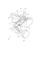
図2に示すように、シフトバイワイヤシステム91は、アクチュエータ40、ディテント機構20、および、パーキングロック機構30等を備える。アクチュエータ40は、回転式であって、モータ50および動力伝達部510から構成される(図3等参照)。
As shown in FIG. 2, the shift-by-
モータ50は、ブラシ付きのDCモータであって、図示しないバッテリからHブリッジ回路等である駆動回路を経由して電力が供給されることで回転し、ディテント機構20の駆動源として機能する。ディテント機構20は、ディテントプレート21、および、ディテントスプリング25等を有し、モータ50から出力された回転駆動力を、パーキングロック機構30へ伝達する。
The
ディテントプレート21は、出力軸15に固定され、モータ50により駆動される。ディテントプレート21のディテントスプリング25側には、2つの谷部211、212、および、谷部211、212を隔てる山部215が設けられる。
ディテントスプリング25は、弾性変形可能な板状部材であり、先端にディテントローラ26が設けられる。ディテントスプリング25は、ディテントローラ26をディテントプレート21の回動中心側に付勢する。無負荷状態において、ディテントスプリング25のスプリング力にてディテントローラ26が落とし込まれる位置を、谷部211、212の最底部とする。
The
ディテントプレート21に所定以上の回転力が加わると、ディテントスプリング25が弾性変形し、ディテントローラ26が谷部211、212間を移動する。ディテントローラ26が谷部211、212のいずれかに嵌まり込むことで、ディテントプレート21の揺動が規制され、パーキングロック機構30の状態が決定され、シフトレンジが固定される。
When a predetermined rotational force or more is applied to the
パーキングロック機構30は、パーキングロッド31、円錐体32、パーキングレバー33、軸部34、および、パーキングギア35を有する。パーキングロッド31は、略L字形状に形成され、一端311側がディテントプレート21に固定される。パーキングロッド31の他端312側には、円錐体32が設けられる。円錐体32は、他端312側にいくほど縮径するように形成される。ディテントローラ26がPレンジに対応する谷部211に嵌まり込む方向にディテントプレート21が回転すると、円錐体32が矢印Pの方向に移動する。
The
パーキングレバー33は、円錐体32の円錐面と当接し、軸部34を中心に揺動可能に設けられる。パーキングレバー33のパーキングギア35側には、パーキングギア35と噛み合い可能な凸部331が設けられる。ディテントプレート21の回転により、円錐体32が矢印P方向に移動すると、パーキングレバー33が押し上げられ、凸部331とパーキングギア35とが噛み合う。一方、円錐体32が矢印notP方向に移動すると、凸部331とパーキングギア35との噛み合いが解除される。
The
パーキングギア35は、減速ギアセット96を経由して車軸95と接続しており(図1参照)、パーキングレバー33の凸部331と噛み合い可能に設けられる。パーキングギア35と凸部331とが噛み合うと、車軸95の回転が規制される。シフトレンジがP以外のレンジであるnotPレンジのとき、パーキングギア35はパーキングレバー33によりロックされず、車軸95の回転は、パーキングロック機構30により妨げられない。また、シフトレンジがPレンジのとき、パーキングギア35はパーキングレバー33によってロックされ、車軸95の回転が規制される。
The
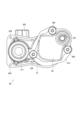
アクチュエータ40を図3~図5に示す。図3は図5のIII-III線断面図である。図3において、モータ50の軸方向を紙面上下方向とし、紙面上側を「一方側」、紙面下側を「他方側」とする。
ハウジング41は、例えばアルミ等の金属で形成され、モータハウジング部411、および、ギアハウジング部412から構成される。モータハウジング部411は、軸方向の一方側に開口する略有底筒状に形成される。ギアハウジング部412は、モータハウジング部411の径方向外側に突出して形成される。ギアハウジング部412の一方側の端面は、モータハウジング部411の一方側の端面と概ね同一平面上に形成されている。ギアハウジング部412の他方側の端面は、モータハウジング部411の軸方向の中間に位置している。換言すると、モータハウジング部411は、他方側に突出している。また、ギアハウジング部412には、出力軸ギア60を収容する出力軸ギア収容部413がモータハウジング部411とは反対側に突出して形成されている。
The
センサカバー43およびギアカバー45は、ハウジング41を挟んで両側に設けられる。センサカバー43は、モータハウジング部411およびギアハウジング部412の一方側に設けられて、ねじ439にてハウジング41に固定される。センサカバー43には、コネクタ435が設けられており、コネクタ435を経由してアクチュエータ40に電力が供給される。また、コネクタ435を経由して外部と信号の送受信を行う。ギアカバー45は、ギアハウジング部412の他方側に設けられ、ねじ459にてハウジング41に固定される。
The
モータ50は、マグネット501、コア502、コイル504、モータ軸505、コミュテータ508、および、図示しないブラシ等を有する。マグネット501は、モータハウジング部411の内周側に固定される。コア502は、マグネット501の径方向内側に設けられ、巻回されているコイル504に電流が流れると、回転力を発生する。モータ軸505は、軸受506、507に回転可能に支持され、コア502と一体となって回転する。コミュテータ508は、ブラシから供給される電流をコイル504に流す。
The
動力伝達部510は、モータ軸505と出力軸15との間に設けられ、モータ50の駆動力を出力軸15に伝達する。動力伝達部510は、ギア51~54、60を有する。ギア51~54、60は、いずれも平歯ギアである。
The
モータギア51およびギア52、53は、ハウジング41に一方側に開口する第1ギア室415に配置される。ギア54および出力軸ギア60は、ハウジング41の他方側に開口する第2ギア室416に配置される。第1ギア室415と第2ギア室416とは、ギア接続シャフト55が挿通される軸孔417で連通している。本実施形態では、モータギア51、ギア54および出力軸ギア60が金属で形成され、ギア52、53が樹脂で形成されている。
The
モータギア51は、モータ軸505の一方側に固定され、モータ軸505と一体に回転する。ギア52は、大径部521および小径部522を有し、シャフト525と一体に回転する。大径部521の径方向外側には平歯が形成され、モータギア51と噛み合う。小径部522の径方向外側には平歯が形成され、ギア53と噛み合う。シャフト525は、ハウジング41に形成される軸孔414に挿入され、回転可能に支持される。
The
ギア53は、筒部531、および、ギア部532を有する。ギア部532は、筒部531の径方向外側に突出して形成される。ギア部532には、ギア52の小径部522と噛み合う平歯が形成されている。ギア部532は、ポジションセンサ68にて絶対角を検出可能な範囲(例えば180°未満)に形成される。筒部531の径方向内側には、シャフト固定部材535が設けられる。シャフト固定部材535は、例えば金属で形成されている。
The
ギア接続シャフト55は、軸受56、57により、ハウジング41に回転可能に支持されている。本実施形態では、軸受56、57は、ボールベアリングであって、軸孔417に圧入されている。軸受を複数とすることで、ギア接続シャフト55の倒れを抑制することができる。また、ギア接続シャフト55の径方向のがたつきを抑制可能であるので、シャフトのたたき等による摩耗の発生を低減することができる。
The
ギア接続シャフト55の一方側は、ギア53の筒部531の径方向内側に設けられるシャフト固定部材535に圧入され、例えばローリングかしめ等にて固定される。これにより、ギア53がギア接続シャフト55の一方側に固定される。ギア接続シャフト55の他方側には、ボルト549によりギア54が固定される。これにより、ギア53の筒部351とギア54とは、ギア接続シャフト55により同軸に接続され、一体となって回転する。本実施形態では、ギア53およびギア54が連結ギア530を構成する。ギア54は、筒部531と略同径に形成され、径方向外側の全周に出力軸ギア60と噛み合う平歯が形成される。
One side of the
出力軸ギア60は、略筒状に形成される出力軸接続部601、および、ギア部602を有する。出力軸接続部601は、径方向外側に設けられるブッシュ61により、ギアカバー45に回転可能に支持される。出力軸接続部601の径方向内側には、出力軸15(図1参照)が圧入固定され、一体となって回転する。ブッシュ61は、ギアカバー45の出力軸保持部455に圧入されている。
The
ギア部602は、出力軸接続部601の径方向外側に突出して形成され、ギア54と噛み合う。本実施形態では、モータギア51とギア52の大径部521との噛み合い箇所が1段目減速段であり、ギア52の小径部522とギア53のギア部532との噛み合い箇所が2段目減速段であり、ギア54と出力軸ギア60のギア部602との噛み合い箇所が3段目減速段である。すなわち本実施形態では、減速段数は3であって、3段目減速段が最終減速段である。
The
ギア52、53等がハウジング41の一方側から組み付けられ、ギア54および出力軸ギア60等がハウジング41の他方側から組み付けられる。ギア53とギア54とを接続するギア接続シャフト55の長さを変えることで、アクチュエータ40と出力軸15を介して組み付けられる相手側の部品に応じ、モータハウジング部411の出代を調整することができる。これにより、搭載の自由度を向上させることができる。
ギア53の筒部531の径方向内側であって、シャフト固定部材535よりもセンサカバー43側には、センサマグネット65が設けられる。センサマグネット65は、例えば幅狭の板状に形成され、ギア53の回転軸を挟んで反対側に設けられる。換言すると、センサマグネット65は、180°離間して設けられている。センサマグネット65は、円環状に形成されるマグネット保持部材66に保持されている。マグネット保持部材66は、筒部531に圧入等により固定される。
A
ポジションセンサ68は、センサカバー43から突出して形成されるセンサ保持部438に保持される。ポジションセンサ68は、センサマグネット65の回転による磁界の変化を検出するホールICを有し、センサ素子が2つのセンサマグネット65の中心に位置するように設けられる。本実施形態では、最終減速段の減速比が6以下であって、ギア53の回転範囲が180°未満であるので、ポジションセンサ68は、ギア53の回転位置を絶対角として検出可能である。また、ギア比換算により、出力軸15の絶対角を演算可能である。ポジションセンサ68は、リニアセンサ、エンコーダまたはレゾルバ等であってもよく、ギア53以外の回転位置を検出するものであってもよい。
The
センサマグネット65が設けられるギア53は、最終減速段より1段手前の減速段を構成している。そのため、出力軸ギア60と比較して伝達トルクが小さく、ギア歯面形状のばらつきや、振動等により発生する偏芯力が小さいため、出力軸ギア60の角度検出を行う場合と比較し、センサ精度の劣化を抑制することができる。また、図1に示すように、アクチュエータ40には、モータ50の電流を検出する電流センサ67、および、温度を検出する温度センサ69が設けられる。
The
車両制御装置80は、アクチュエータ制御ユニット(以下、「act-ECU」)81、および、MG制御ユニット(以下、「MG-ECU」)82を有する。act-ECU81およびMG-ECU82は、マイコン等を主体として構成され、内部にはいずれも図示しないCPU、ROM、RAM、I/O、及び、これらの構成を接続するバスライン等を備えている。ECUにおける各処理は、ROM等の実体的なメモリ装置(すなわち、読み出し可能非一時的有形記録媒体)に予め記憶されたプログラムをCPUで実行することによるソフトウェア処理であってもよいし、専用の電子回路によるハードウェア処理であってもよい。
The
車両制御装置80は、レンジセンサ37、ポジションセンサ68、温度センサ69、傾斜角センサ87、および、操舵角センサ88の検出値を取得し、これらの検出値を各種制御に利用可能である。また、コイル504の通電制御に、ディテント機構20と接続される変速機7の油温(以下、「TM油温」という。)等を用いてもよい。変速機7は、トランスアクスル等であってもよい。また、車両制御装置80は、ブレーキECU85と各種情報を送受信可能に設けられている。
The
レンジセンサ37は、アクチュエータ40の外部であって、パーキングレバー33の近傍に設けられており、シフトレンジがPレンジおよびnotPレンジの一方から他方へ切り替わったことを判定するセンサである。なお、ポジションセンサ68は、アクチュエータ40の内部に設けられており、回転体の回転を連続的に検出可能である。
The
act-ECU81は、機能ブロックとして、アクチュエータ駆動制御部811等を有し、ドライバ要求シフトレンジ、ブレーキスイッチからの信号および車速等に基づいてモータ50への通電を制御することで、パーキングレバー33の動作を制御する。
The act-
MG-ECU82は、機能ブロックとして、MG駆動制御部821、および、停滞判定部822等を有する。MG駆動制御部821は、インバータ71を構成するスイッチング素子のオンオフ作動を制御することで、主機モータ70の駆動を制御する。停滞判定部822は、ポジションセンサ68の検出値θsnsに基づき、アクチュエータ40の停滞を判定する。
The MG-
本実施形態では、act-ECU81とMG-ECU82とが別途に設けられているが、1つのECUとして構成してもよい。また、act-ECU81をアクチュエータ40と一体に設けてもよい。さらにまた、例えば、停滞判定部822をact-ECU81側に設ける、と言った具合に、後述の各種判断処理等は、act-ECU81またはMG-ECU82のいずれで実行してもよい。
In this embodiment, act-
上述の通り、モータ50の駆動により、パーキングロックを解除する。図6に示すように、車両100が傾斜した状態にて停止している場合、車両100の前後方向に車重Wおよび傾斜角θiに応じた荷重L(式(1)参照)がかかる。図7に示すように、車重Wおよび傾斜角θiに応じた荷重Lが、パーキングレバー33とパーキングギア35とが噛み合う面圧発生部位Psにかかる。
As described above, the parking lock is released by driving the
L=W×sinθi ・・・(1) L=W×sinθi...(1)
そのため、パーキングギア35からパーキングレバー33を引き抜くとき、車両100が傾斜状態であると、噛み合い荷重の分、平坦路にある場合よりも大きなトルクを要する。以下適宜、パーキングギア35からパーキングレバー33の凸部331を引き抜くことを「P抜き」とする。
Therefore, when the
図8は、横軸をアクチュエータ40の回転角、縦軸をアクチュエータ40のトルクとする。図8に示すように、噛み合い面圧がかかっている状態にてP抜きを行う場合、実線で示すディテント機構20のディテントを切り替える分のトルクに加え、破線で示す噛み合い面圧成分のトルクが必要になる。そのため、例えば一点鎖線で示すように、アクチュエータ40の出力可能なトルクが比較的小さい場合、アクチュエータ40の出力トルクTactのみではP抜きができない虞がある。また、噛み合い面圧成分のトルクをアクチュエータ40で賄う場合、アクチュエータ40の体格が大型化する。
In FIG. 8, the horizontal axis represents the rotation angle of the
図9は、横軸をアクチュエータ40の入力電圧V、縦軸をアクチュエータ40の出力トルクTactとする。また、平坦路でのP抜きに要するトルクをTp_f、想定される最大傾斜でのP抜きに要するトルクをTp_maxとする。アクチュエータ40は、温度が高いとき、および、電圧が低いとき、出力トルクTactが低下するため、車両傾斜状態、温度条件および入力電圧Vによっては、モータ50のトルクのみではP抜きできない領域が存在している。
In FIG. 9, the horizontal axis represents the input voltage V of the
そこで本実施形態では、必要に応じてP抜き時に主機モータ70を駆動し、噛み合い面圧成分のトルクをキャンセルするトルクを発生させる。これにより、MGトルクTmgにより、車重による噛み合い面圧成分を低減することが可能であるので、モータ50のみでP抜きを行う場合と比較し、モータ50に求められるトルクを下げることができ、モータ50を小型化可能である。また、モータ50の駆動に係る図示しない駆動回路の通電量や熱負荷を低減することができる。
Therefore, in the present embodiment, the
本実施形態では、ポジションセンサ68の検出値θsnsに基づき、モータ50および主機モータ70の駆動を制御する。アクチュエータ制御処理を図10のフローチャートに基づいて説明する。この処理は、シフトレンジがPレンジであるとき、アクチュエータ駆動制御部811にて所定の周期で実行される。以下、ステップS101等の「ステップ」を省略し、単に記号「S」と記す。
In this embodiment, the drive of the
S101では、アクチュエータ駆動制御部811は、モータ50が駆動中か否か判断する。モータ50が駆動中であると判断された場合(S101:YES)、S104へ移行する。モータ50が駆動中ではないと判断された場合(S101:NO)、S102へ移行する。
In S101, the actuator
S102では、アクチュエータ駆動制御部811は、notP切替指示があるか否か判断する。ここでは、MG-ECU82からの切替指示に基づいて判断するが、シフト信号等に基づいて内部的に判断してもよい。notP切替指示がないと判断された場合(S102:NO)、S103の処理をスキップする。notP切替指示があると判断された場合(S102:YES)、S103へ移行する。
In S102, the actuator
S103では、アクチュエータ駆動制御部811は、PレンジからnotPレンジに切替可能な目標値θ*を設定し、ポジションセンサ68の検出値θsnsが目標値θ*となるように、モータ50を駆動する。
In S103, the actuator
モータ50が駆動中であると判断された場合(S101:YES)に移行するS104では、アクチュエータ駆動制御部811は、ポジションセンサ68の検出値θsnsが目標値θ*に到達したか否か判断する。検出値θsnsが目標値θ*に到達していないと判断された場合(S104:NO)、モータ50の駆動制御を継続する。検出値θsnsが目標値θ*に到達したと判断された場合(S104:YES)、S105へ移行し、notPレンジへの切り替えが完了したと判定し、モータ50を停止する。また、act-ECU81は、切り替えが完了した旨の情報を、MG-ECU82へ送信する。
In S104, which is proceeded to when it is determined that the
MG制御処理を図11のフローチャートに基づいて説明する。この処理は、シフトレンジがPレンジであるとき、MG-ECU82にて所定の周期で実行される。
The MG control process will be explained based on the flowchart of FIG. 11. This process is executed by the MG-
S201では、MG-ECU82は、notP切替要求があるか否か判断する。notP切替要求がないと判断された場合(S201:NO)、S202以降の処理をスキップする。notP切替要求があると判断された場合(S201:YES)、S202へ移行する。
In S201, the MG-
S202では、MG-ECU82は、モータ50(図中、「act」と記載)が駆動中か否か判断する。モータ50が駆動中ではないと判断された場合、(S202:NO)、S203へ移行し、notP切替指示をact-ECU81に送信する。モータ50が駆動中であると判断された場合(S202:YES)、S204へ移行する。
In S202, the MG-
S204では、停滞判定部822は、ポジションセンサ68の検出値θsnsが停滞しているか否かを判断する。ここでは、検出値θsnsの最大値が更新されない場合、検出値θsnsが停滞していると判断する。検出値θsnsが停滞していると判断された場合(S204:YES)、S207へ移行する。検出値θsnsが停滞していないと判断された場合(S204:NO)、S205へ移行する。
In S204, the
S205では、MG駆動制御部821は、MGトルクTmgが走行用トルクTd以下か否か判断する。設定されている走行用トルクが0であれば、Td=0とする。MGトルクTmgが走行用トルクTd以下であると判断された場合(S205:YES)、S215へ移行する。なお、走行用トルクTdが0ではなく、MGトルクTmgが走行用トルクTdより小さい場合は、別途の処理によりMGトルクTmgを制御する。MGトルクTmgが走行用トルクTdより大きいと判断された場合(S205:NO)、S206へ移行する。
In S205, the MG
S206では、停滞判定部822は、検出値θsnsがPレンジ解除域か否か判断する。本実施形態では、Pレンジ解除位置θyと切替完了位置との間の範囲をPレンジ解除域とする。検出値θsnsがPレンジ解除域であると判断された場合(S206:YES)、S214へ移行し、MGトルクTmgを減少させる。検出値θsnsがPレンジ解除域に到達していないと判断された場合(S206:NO)、S207へ移行する。
In S206, the
S207では、停滞判定部822は、停滞カウント値C1が停滞判定時間Xth1に対応する停滞判定閾値Cth1以下か否か判断する。停滞カウント値C1が停滞判定閾値Cth1以下であると判断された場合(S207:YES)、S208へ移行し、停滞カウント値Cをカウントアップする。停滞カウント値C1が停滞判定閾値Cth1より大きいと判断された場合(S207:YES)、S209へ移行する。
In S207, the
S209では、MG駆動制御部821は、MGトルクTmgが初期トルク値Tsに到達したか否か判断する。初期トルク値Tsは、噛み合い面圧を低減可能な値であって、例えばモータ50が動き出せるようになる値に設定される。また、初期トルク値Tsは、学習値としてもよい。MGトルクTmgが初期トルク値Tsに到達していないと判断された場合(S209:NO)、S210へ移行し、MGトルク指令値Tmg*を初期トルク値Tsとする。MGトルクTmgが初期トルク値Tsに到達していると判断された場合(S209:YES)、S211へ移行する。
In S209, the MG
S211では、MG駆動制御部821は、MGトルクTmgが上限トルク値Tuに到達したか否か判断する。上限トルク値Tuは、噛み合い面圧低減制御における最大トルクであって、アクチュエータ40が確実に作動するように噛み合い面圧を低減可能な値に設定される。MGトルクTmgが上限トルク値Tuに到達していないと判断された場合(S211:NO)、S212へ移行し、MGトルク指令値Tmg*を徐変量ΔT増加させる。MGトルクTmgが上限トルク値Tuに到達していると判断された場合(S211:YES)、S213へ移行し、MGトルク指令値Tmg*を上限トルク値Tuとする。
In S211, the MG
S215で、MG-ECU82は、notPレンジへの切り替えが完了したか否か判断する。notPレンジへの切り替えが完了していないと判断された場合(S215:NO)、現在の状態を維持する。notPレンジへの切り替えが完了したと判断された場合(S215:YES)、S216へ移行し、P抜き時の面圧低減制御を完了する。
In S215, the MG-
P抜き制御処理を図12のタイムチャートに基づいて説明する。図12では、横軸を共通時間軸とし、上段から、シフト指示、MGトルク指令値Tmg*、MGトルクTmg、ポジションセンサ68の目標値、ポジションセンサ68の検出値θsnsを示す。ポジションセンサ68の値は、適宜対応するレンジとして記載した。また、P抜き処理中において、走行用トルクTd=0であるものとして説明する。後述の実施形態に係るタイムチャートも同様である。
The P removal control process will be explained based on the time chart of FIG. 12. In FIG. 12, the horizontal axis is a common time axis, and from the top, a shift instruction, MG torque command value Tmg * , MG torque Tmg, target value of the
時刻x10にて、シフト指示がPレンジからnotPレンジに切り替わると、モータ50の駆動を開始する。噛み合い面圧が発生していない場合、破線で示すように、モータ50は停滞せず、モータ50のトルクにてP抜きが完了する。
At time x10, when the shift instruction is switched from the P range to the notP range, driving of the
モータ50のトルクでのP抜き不能な噛み合い面圧が発生している場合、時刻x11にて、Pレンジ解除位置θyよりも検出値θsnsが小さい位置にてポジションセンサ68の検出値θsnsが停滞する。
When the torque of the
時刻x11から停滞判定時間Xth1が経過した時刻x12において、アクチュエータ40の停滞が発生していると判定し、MGトルク指令値Tmg*を初期トルク値Tsとし、主機モータ70を駆動する。また、MGトルク指令値Tmg*を漸増させていく。MGトルクTmgは、MGトルク指令値Tmg*の変化に遅れて追従するが、追従遅れの詳細については説明を省略する。
At time x12 when stagnation determination time Xth1 has elapsed from time x11, it is determined that stagnation of
時刻x13にて、アクチュエータ40の停滞が解消され、時刻x14にて、検出値θsnsがPレンジ解除位置θyに到達すると、MGトルク指令値Tmg*を低下させる。なお、アクチュエータ40の停滞が解消しない場合、一点鎖線で示すように、MGトルク指令値Tmg*を上限トルク値Tuまで増加させる。また、初期トルク値Ts=0とし、主機モータ70が停止している状態からMGトルクTmgを漸増させるようにしてもよい。また、初期トルク値Ts=上限トルク値Tuとし、時刻x12から上限トルク値Tuを出力するようにしてもよい。
At time x13, the stagnation of the
レンジ切り替えが完了した時刻x15にて、MGトルク指令値Tmg*を0とする。図12の例では、レンジ切替完了のタイミングとMGトルク指令値Tmg*が0になるタイミングとが概ね同時となっているが、レンジ切替完了前にMGトルク指令値Tmg*が0になっていてもよい。 At time x15 when range switching is completed, the MG torque command value Tmg * is set to 0. In the example of FIG. 12, the timing at which range switching is completed and the timing at which MG torque command value Tmg * becomes 0 are approximately the same time, but MG torque command value Tmg * becomes 0 before range switching is completed. Good too.
本実施形態では、車両傾斜等により、噛み合い面圧がパーキングロック機構30に発生しているとき、アクチュエータ40側に設けられているポジションセンサ68の検出値θsnsに基づき、主機モータ70による噛み合い面圧低減制御の開始を判定する。これにより、アクチュエータ40の停滞を速やかに判定可能であり、主機モータ70により面圧低減制御開始までの時間を短縮することができ、応答性を向上可能である。また、停滞によるモータ50の発熱や、モータ50の駆動に係る素子等の発熱を抑制することができる。
In this embodiment, when meshing surface pressure is generated in the
また、本実施形態では、レンジ切替完了よりも手前側であるPレンジ解除位置θyに検出値θsnsが到達した段階で、MGトルクTmgを低減させる。これにより、レンジ切替完了までMGトルクTmgを増加させる、もしくは、維持する場合と比較し、主機モータ70の発熱を抑制することができる。
Furthermore, in this embodiment, the MG torque Tmg is reduced at the stage when the detected value θsns reaches the P range release position θy, which is closer to the end of range switching. Thereby, heat generation of the
以上説明したように、車両制御装置80は、車両100の駆動源である主機モータ70と、パーキングロック機構30と、アクチュエータ40と、を備える車両駆動システム90を制御する。パーキングロック機構30は、車軸95に接続されるパーキングギア35、および、パーキングギア35と噛み合い可能であるパーキングレバー33を有し、パーキングギア35とパーキングレバー33とが噛み合うことで車軸95をロック可能である。アクチュエータ40は、パーキングレバー33を駆動可能である。本実施形態のアクチュエータ40は、噛み合い面圧が生じているとき、パーキングロックを解除不能な使用環境領域が存在している。
As described above, the
車両制御装置80は、アクチュエータの駆動を制御するアクチュエータ駆動制御部811と、主機モータ70の駆動を制御するMG駆動制御部821と、停滞判定部822と、を備える。停滞判定部822は、アクチュエータ40の駆動状態に応じて変化する物理量を検出するセンサ部の検出値に基づいて、アクチュエータ40の停滞を判定する。本実施形態のセンサ部は、アクチュエータ40の回転角度を検出するポジションセンサ68である。
The
パーキングギア35とパーキングレバー33との噛み合い箇所において発生する噛み合い面圧を主機モータ70の駆動により低減する噛み合い面圧低減制御を行っているとき、MG駆動制御部821は、センサ部の検出値に基づき、主機モータ70のトルクであるMGトルクTmgを減少させる。詳細には、MG駆動制御部821は、センサ部の検出値に基づき、アクチュエータ40の停滞が解消されたと判定された場合、MGトルクTmgの減少を開始する。
When performing meshing surface pressure reduction control that reduces the meshing surface pressure generated at the meshing point between the
これにより、アクチュエータ40を小型化しつつ、確実にP抜きを行うことができる。また、アクチュエータ40の駆動に応じて変化する信号に基づいて、MGトルクTmgを減少させることで、主機モータ70における発熱を抑制可能である。また、パーキングレバー33がパーキングギア35の反対側に衝突することでのショックの発生を防ぐことができる。
Thereby, P can be removed reliably while reducing the size of the
停滞判定部822は、ポジションセンサ68の検出値がPレンジ解除位置θyに到達した場合、アクチュエータ40の停滞が解消されたと判定する。これにより、レンジ切替完了までMGトルクTmgを増加、もしくは、維持した場合と比較し、主機モータ70の発熱を抑制することができる。また、車重要因による負荷トルク増加の影響がない位置までアクチュエータ40を作動させた後に、MGトルクTmgを減少させることで、P抜きの失敗を防ぐことができる。
The
(第2実施形態)
第2実施形態を図13~図15に示す。第2実施形態~第5実施形態は、主に主機モータ70の処理が異なっているので、この点を中心に説明する。図13のフローチャートに示すMG制御処理において、S231~S233の処理は、図11中のS201~S203の処理と同様である。
(Second embodiment)
A second embodiment is shown in FIGS. 13 to 15. The second to fifth embodiments differ mainly in the processing of the
S232にて肯定判断された場合に移行するS234では、停滞判定部822は、ポジションセンサ68の検出値θsnsが到達判定値θrに到達したか否か判断する。到達判定値θrについて、図14に基づいて説明する。図14は、上段にポジションセンサ68の検出値θsns、下段にモータ50の出力トルクTactを示す。出力トルクTactは、噛み合い面圧が発生していない場合を実線、噛み合い面圧が発生している場合を破線で示す。
In S234, which is proceeded to when an affirmative determination is made in S232, the
図14の下段に示すように、ディテントローラ26がディテントプレート21の山部215を乗り越えるまでの範囲において、モータ軸が出力軸15に対して先行する。ディテントローラ26が山部215を乗り越えると、ディテントスプリング25のスプリング力により出力軸15が先行するため、出力トルクTactが負となる。ディテントローラ26が山部215を乗り越えるタイミングのポジションセンサ68の検出値θsnsを吸い込み開始位置θx、噛み合い面圧のピークとなる検出値θsnsをピーク位置θpとすると、到達判定値θrは、ピーク位置θpと吸い込み開始位置θxとの間の範囲R1内に設定される。また、到達判定値θrは、ピーク位置θpとPレンジが解除されるPレンジ解除位置θyとの間の範囲R2内に設定してもよい。Pレンジ解除位置θyは、レンジセンサ37の検出値がPからnotPに切り替わる位置である。
As shown in the lower part of FIG. 14, the motor shaft precedes the
図13に戻り、検出値θsnsが到達判定値θrに到達したと判断された場合(S234:YES)、S242へ移行する。到達判定値θrを通過している場合も、肯定判断する。すなわち、モータ50の駆動にて到達判定値θrを通過していれば、噛み合い面圧成分に起因する停滞は発生しないため、主機モータ70を駆動せずにP抜き可能である。検出値θsnsが到達判定値θrに到達していないと判断された場合(S234:NO)、S235へ移行する。
Returning to FIG. 13, if it is determined that the detected value θsns has reached the attainment determination value θr (S234: YES), the process moves to S242. An affirmative determination is also made when the arrival determination value θr has been passed. That is, if the drive of the
S235では、停滞判定部822は、カウント値C2が到達判定時間Xth2に応じて設定される到達判定閾値Cth2以下か否か判断する。本実施形態の到達判定時間Xth2は、噛み合い面圧が発生していないときに、到達判定値θrに到達するのに要する時間に応じて設定される。カウント値C2が到達判定閾値Cth2以下であると判断された場合(S235:YES)、S236へ移行し、カウント値C2をカウントアップする。カウント値C2が到達判定閾値Cth2より大きいと判断された場合(S235:NO)、S237へ移行する。
In S235, the
S242の処理は、図11中のS205の処理と同様であり、否定判断された場合、S243へ移行し、肯定判断された場合、S244へ移行する。S243~S245の処理は、図11中のS214~S216の処理と同様である。 The process of S242 is similar to the process of S205 in FIG. 11, and if the determination is negative, the process moves to S243, and if the determination is affirmative, the process moves to S244. The processing from S243 to S245 is similar to the processing from S214 to S216 in FIG.
本実施形態のP抜き制御処理を図15のタイムチャートに基づいて説明する。時刻x20にて、シフト指示がPレンジからnotPレンジに切り替わると、モータ50の駆動を開始し、計時が開始される。時刻x21にて、到達判定値θrより手前にて、ポジションセンサ68の検出値θsnsが停滞している。モータ50の駆動開始から到達判定時間Xth2が経過した時刻x22において、停滞状態が継続しているので、主機モータ70の駆動を開始する。時刻x23にて、ポジションセンサ68の検出値θsnsが到達判定値θrに到達すると、MGトルク指令値Tmg*の低減を開始する。MGトルク低減開始以降の処理は、上記実施形態と同様であるので、説明を省略する。
The P removal control process of this embodiment will be explained based on the time chart of FIG. 15. At time x20, when the shift instruction is switched from the P range to the notP range, driving of the
車両駆動システム90は、ディテント機構20を備えている。ディテント機構20は、複数の谷部211、212が形成され、パーキングレバー33と接続されているディテントプレート21、アクチュエータ40の駆動により谷部211、212を移動可能であるディテントローラ26、および、ディテントローラ26を谷部211、212に嵌まり合う方向に付勢するディテントスプリング25を有する。
本実施形態では、到達判定値θrは、車軸95にかかる荷重による噛み合い面圧がピークとなるピーク位置θpとPレンジ以外レンジであるnotPレンジに対応する谷部212にディテントローラ26をディテントスプリング25の付勢力により移動可能な位置である吸い込み開始位置θxとの間に設定されている。
In this embodiment, the attainment determination value θr is determined by moving the
また、到達判定値θrは、車軸95にかかる荷重による噛み合い面圧がピークとなるピーク位置θpと、Pレンジが解除されるPレンジ解除位置θyと、の間に設定してもよい。これにより、アクチュエータ40の停滞が解消されたタイミングでMGトルクTmgを低減させることができ、主機モータ70の発熱を抑制することができる。また、上記実施形態と同様の効果を奏する。
Further, the attainment determination value θr may be set between the peak position θp where the engagement surface pressure due to the load applied to the
(第3実施形態)
第3実施形態を図16~図18に示す。図16は、初期トルク値Tsおよび上限トルク値Tuの設定範囲を概念的に説明する図である。パーキングレバー33の凸部331の嵌め合い位置は、バックラッシュの範囲内で成り行きであって、バックラッシュの範囲内に位置している場合、面圧は発生しない。また、車両100の傾斜等で凸部331とパーキングギア35とが当接すると、車重成分に応じた噛み合い面圧が発生する(図8参照)。
(Third embodiment)
A third embodiment is shown in FIGS. 16 to 18. FIG. 16 is a diagram conceptually explaining the setting range of the initial torque value Ts and the upper limit torque value Tu. The fitting position of the
そのため、車重要因にて発生する噛み合い面圧を低減するように主機モータ70を駆動する。初期トルク値Tsは、0以上、面圧が0となる範囲に設定される。また、上限トルク値Tuは、車重成分とMGトルクTmgとの差分である残留車重成分が、モータ50でのP抜き可能範囲となる、またはそれ以上となるように設定される。
Therefore, the
ここで、MGトルクTmgが車重成分より大きくなると、車両100に推進力が発生する。そこで本実施形態では、P抜き制御における主機モータ70の駆動により車両100が意図せず発進しないように、ブレーキ力を増加させる。なお、第1実施形態等においても、噛み合い面圧低減制御にて主機モータ70を駆動する場合、ブレーキ荷重を高めるようにしてもよい。
Here, when the MG torque Tmg becomes larger than the vehicle weight component, a propulsive force is generated in the
本実施形態のMG制御処理を図17のフローチャートに基づいて説明する。S261~S264の処理は、図11中のS201~S204の処理と同様である。S264にて肯定判断された場合、S265へ移行し、否定判断された場合、S274へ移行する。 The MG control process of this embodiment will be explained based on the flowchart of FIG. 17. The processing from S261 to S264 is similar to the processing from S201 to S204 in FIG. If an affirmative determination is made in S264, the process proceeds to S265, and if a negative determination is made, the process proceeds to S274.
S265では、停滞判定部822は、検出値θsnsが実施判定閾値θth以下か否か判断する。実施判定閾値θthは、例えばレンジセンサ37がPレンジからnotPレンジに切り替わるPレンジ解除位置θyに応じて設定される。検出値θsnsが実施判定閾値θthより大きいと判断された場合(S265:NO)、S274へ移行する。検出値θsnsが実施判定閾値θthより大きい場合、メカロック等の噛み合い面圧以外の要因での停滞である蓋然性が高いため、MGトルクによる噛み合い面圧低減処理を行わない。検出値θsnsが実施判定閾値θth以下であると判断された場合(S265:YES)、S266へ移行する。
In S265, the
S266~S269の処理は、図11中のS207~S210の処理と同様である。S269に続いて以降するS270では、車両制御装置80は、ブレーキ荷重を増加させる旨の指令をブレーキECU85に送信する。なお、噛み合い面圧低減処理にてブレーキ荷重を増加させない場合は、S270の処理を省略すればよい。
The processing in S266 to S269 is similar to the processing in S207 to S210 in FIG. In S270 following S269,
S271~S273の処理は、図11中のS211~S213の処理と同様である。S264にて否定判断された場合に移行するS274の処理は、図11中のS205と同様であって、否定判断された場合、S275へ移行し、肯定判断された場合、S276へ移行する。S275~S277の処理は、図11中のS214~S216の処理と同様である。 The processing in S271 to S273 is similar to the processing in S211 to S213 in FIG. The process of S274, which is executed when a negative determination is made in S264, is the same as S205 in FIG. 11. When a negative determination is made, the process proceeds to S275, and when an affirmative determination is made, the process proceeds to S276. The processing from S275 to S277 is similar to the processing from S214 to S216 in FIG.
本実施形態のP抜き制御処理を図18のタイムチャートに基づいて説明する。図18では、横軸を共通時間軸とし、上段から、シフト指示、MGトルク指令値Tmg*、MGトルクTmg、ポジションセンサ68の目標値、ポジションセンサ68の検出値θsnsを示す。時刻x30~時刻x32の処理は、図12中の時刻x10~時刻x12の処理と同様である。また、時刻x32にて、ブレーキ荷重を増加させる。
The P removal control process of this embodiment will be explained based on the time chart of FIG. 18. In FIG. 18, the horizontal axis is a common time axis, and from the top, a shift instruction, MG torque command value Tmg * , MG torque Tmg, target value of the
時刻x33にて、アクチュエータ40の停滞が解消し、ポジションセンサ68の停滞が解消されると、MGトルク指令値Tmg*を低下させる。MGトルク低減開始以降の処理は、上記実施形態と同様であるので、説明を省略する。また、図18では、ブレーキ荷重を増加した状態が継続されているが、時刻x35にて、ブレーキ荷重を増加前の荷重に戻してもよい。
At time x33, when the stagnation of the
本実施形態では、車両制御装置80は、噛み合い面圧低減制御により、主機モータ70を駆動している場合、噛み合い面圧低減制御を行っていない場合よりもブレーキ荷重を大きくする。これにより、意図しない車両100の発進を防ぐことができる。また、上記実施形態と同様の効果を奏する。
In this embodiment, the
(第4実施形態)
第4実施形態を図19に示す。図19のフローチャートに示すMG制御処理において、図17のS270が省略されており、S264に替えて、S281となっている点が異なっており、その他の点は図17と同様である。
(Fourth embodiment)
A fourth embodiment is shown in FIG. The MG control process shown in the flowchart of FIG. 19 is the same as FIG. 17 except that S270 in FIG. 17 is omitted and S281 is performed instead of S264.
S262にて肯定判断された場合に移行するS281では、ポジションセンサ68の検出値θsnsに基づき、アクチュエータ40の回転速度が速度閾値以下か否か判定する。アクチュエータ40の回転速度が速度閾値以下であると判断された場合(S281:YES)、S265へ移行する。アクチュエータ40の回転速度が速度閾値より大きいと判断された場合(S281:NO)、アクチュエータ40の停滞が解消したと判定し、S274へ移行する。
In S281, which is proceeded to when an affirmative determination is made in S262, it is determined based on the detected value θsns of the
停滞判定部822は、アクチュエータ40が停滞している状態から、アクチュエータ40の回転速度が速度判定閾値を超えた場合、アクチュエータ40の停滞が解消されたと判定する。これにより、アクチュエータ40の停滞が解消されたタイミングでMGトルクTmgを低減させることができ、主機モータ70の発熱を抑制することができる。また、上記実施形態と同様の効果を奏する。
The
(第5実施形態)
第5実施形態を図20および図21に示す。図20のフローチャートに示すMG制御処理において、図17中のS270が省略されており、S264に替えて、S282となっている点が異なっており、その他の点は図17と同様である。
(Fifth embodiment)
The fifth embodiment is shown in FIGS. 20 and 21. The MG control process shown in the flowchart of FIG. 20 is the same as FIG. 17 except that S270 in FIG. 17 is omitted and S282 is used instead of S264.
S262にて肯定判断された場合に移行するS282では、主機モータ70のモータ電流Imが停滞しているか否かを判断する。モータ電流Imが停滞していると判断された場合(S282:YES)、S265へ移行し、モータ電流Imが停滞していないと判断された場合(S282:NO)、S274へ移行する。
In S282, which is proceeded to when an affirmative determination is made in S262, it is determined whether the motor current Im of the
本実施形態のP抜き制御処理を図21のタイムチャートに基づいて説明する。図21では、横軸を共通時間軸とし、上段から、シフト指示、MGトルク指令値Tmg*、MGトルクTmg、ポジションセンサ68の目標値、モータ電流Im、ポジションセンサ68の検出値θsnsを示す。
The P removal control process of this embodiment will be explained based on the time chart of FIG. 21. In FIG. 21, the horizontal axis is a common time axis, and from the top, a shift instruction, MG torque command value Tmg * , MG torque Tmg, target value of
時刻x40にて、シフト指示がPレンジからnotPレンジに切り替わると、モータ50の駆動を開始する。噛み合い面圧が発生していない場合、破線で示すように、モータ50は停滞せず、モータ50のトルクにてP抜きが完了する。また、モータ電流Imは、突入電流のピークを過ぎると、低下する。
At time x40, when the shift instruction is switched from the P range to the notP range, driving of the
モータ50のトルクでのP抜き不能な噛み合い面圧が発生している場合、時刻x41において、実施判定閾値θthよりも検出値θsnsが小さい位置にてポジションセンサ68の検出値θsnsが停滞する。また、モータ電流Imは最大電流Imaxにて停滞する。時刻x41から停滞判定時間Xth1が経過した時刻x42において、主機モータ70を駆動し、MGトルクTmgにより噛み合い面圧を低減させる。
When the torque of the
時刻x43にて、アクチュエータ40の停滞が解消され、モータ電流Imが最大電流Imaxから低下することで更新されると、MGトルク指令値Tmg*を低下させる。MGトルク低減開始以降の処理は、上記実施形態と同様であるので、説明を省略する。
At time x43, when the stagnation of the
アクチュエータ40は、モータ50を含む。本実施形態では、モータ50の電流を検出する電流センサ67が「センサ部」に対応している。停滞判定部822は、電流センサ67の検出値に基づき、モータ50の電流が停滞している状態から減少に転じた場合、アクチュエータ40の停滞が解消されたと判定する。このように構成しても、アクチュエータ40の停滞が解消されたタイミングでMGトルクTmgを低減させることができ、主機モータ70の発熱を抑制することができる。また、上記実施形態と同様の効果を奏する。
(第6実施形態)
第6実施形態を図22に基づいて説明する。第6実施形態~第8実施形態は、S214等におけるTmg低減処理が異なっているので、この点を中心に説明する。噛み合い面圧を低減するのに比較的大きなMGトルクTmgを要する場合、車軸95の捩れが大きいため、急激にMGトルクTmgを低減させると、ショックが発生する虞がある。
(Sixth embodiment)
A sixth embodiment will be described based on FIG. 22. The sixth to eighth embodiments differ in the Tmg reduction processing in S214 and the like, so this point will be mainly explained. If a relatively large MG torque Tmg is required to reduce the meshing surface pressure, the torsion of the
そこで本実施形態では、傾斜角θiおよび停滞解消時のモータ電流Imに応じて、MGトルクTmgの減少速度を可変にする。具体的には、傾斜角θiが大きいほど、MGトルクTmgの減少速度を小さくする。また、停滞解消時のモータ電流Imが大きいほど、MGトルク減少速度を小さくする。これにより、車軸95の捩れが開放されることによるショックを低減可能である。
Therefore, in this embodiment, the rate of decrease of the MG torque Tmg is made variable according to the inclination angle θi and the motor current Im when the stagnation is cleared. Specifically, the larger the inclination angle θi, the smaller the rate of decrease in the MG torque Tmg. Furthermore, the larger the motor current Im when the stagnation is resolved, the smaller the MG torque reduction speed is made. Thereby, it is possible to reduce the shock caused by the untwisting of the
図22では、傾斜角θiに応じた3つのマップを示しているが、マップ数は2または4以上であってもよいし、モータ電流Imによらず、傾斜角θiに基づいてMGトルク減少速度を設定するようにしてもよい。マップ演算に替えて、関数等を用いてモータトルク減少速度を設定するようにしてもよい。第7実施形態および第8実施形態についても同様である。 Although FIG. 22 shows three maps depending on the inclination angle θi, the number of maps may be 2 or 4 or more, and the MG torque reduction rate may be determined based on the inclination angle θi regardless of the motor current Im. may be set. Instead of map calculation, the motor torque reduction speed may be set using a function or the like. The same applies to the seventh embodiment and the eighth embodiment.
MG駆動制御部821は、車両100の傾斜状態に応じ、MGトルクTmgの減少速度を可燃にする。また、MG駆動制御部821は、主機モータ70の電流に応じ、MGトルクTmgの減少速度を可変にする。これにより、車軸95の捩れ量に応じ、適切にMGトルクTmgを低減させることができるので、ショックの発生を抑制することができる。また、上記実施形態と同様の効果を奏する。
The MG
(第7実施形態)
第7実施形態を図23に基づいて説明する。本実施形態では、主機モータ70の発熱量が大きい場合、主機モータ70を保護すべく、MGトルクTmgを速やかに低減させる。主機モータ70の発熱量は、モータ電流Imの2乗×通電時間に比例する。そのため、モータ電流Imが大きく、通電時間が長いほど、主機モータ70の発熱量が大きくなる。
(Seventh embodiment)
A seventh embodiment will be described based on FIG. 23. In this embodiment, when the amount of heat generated by the
そこで本実施形態では、モータ電流Imの増加速度、および、停滞解消時のモータ電流Imに応じて、MGトルクTmgの減少速度を可変にする。具体的には、停滞解消時のモータ電流Imが大きいほど、MGトルク減少速度を大きくする。また、停滞解消までのMGトルク増加速度が小さいほど、停滞解消後のMGトルク減少速度を大きくする。これにより、主機モータ70の発熱を抑制可能である。
Therefore, in this embodiment, the rate of decrease in MG torque Tmg is made variable in accordance with the rate of increase in motor current Im and the rate of decrease in motor current Im when the stagnation is resolved. Specifically, the greater the motor current Im when the stagnation is resolved, the greater the MG torque reduction speed. Furthermore, the smaller the MG torque increase speed until the stagnation is resolved, the greater the MG torque decrease speed after the stagnation is resolved. Thereby, heat generation of the
本実施形態では、主機モータ70の発熱量に応じ、MGトルクTmgの減少速度を可変にする。具体的には、主機モータ70の発熱量が大きく、発熱余裕度が小さい場合、MGトルクTmgの減少速度を大きくする。これにより、主機モータ70を熱的に保護可能である。また上記実施形態と同様の効果を奏する。
In this embodiment, the rate of decrease of the MG torque Tmg is made variable according to the amount of heat generated by the
(第8実施形態)
第8実施形態を図24に基づいて説明する。本実施形態では、主機モータ70の応答性が低い場合、MGトルクTmgをゆっくり減少させることでショックを抑制する。具体的には、入力電圧Vが小さい場合、MGトルク減少速度を小さくする。また、アクチュエータ温度tmpが低い場合、MGトルク減少速度を小さくする。
(Eighth embodiment)
The eighth embodiment will be described based on FIG. 24. In this embodiment, when the responsiveness of the
本実施形態では、アクチュエータ40の温度に応じ、MGトルクTmgの減少速度を可変にする。本実施形態では、温度センサ69の検出値をアクチュエータ温度tmpとするが、これに替えて、TM油温を用いてもよい。これにより、アクチュエータ40の応答性に応じ、MGトルクTmgを適切に低減させることができるので、ショックの発生を抑制することができる。また、上記実施形態と同様の効果を奏する。
In this embodiment, the rate of decrease of the MG torque Tmg is made variable according to the temperature of the
実施形態では、ポジションセンサ68が「センサ部」および「回転角センサ」、電流センサ67が「センサ部」、アクチュエータ40の回転に応じて変化するセンサマグネット65の磁界およびモータ50の電流が「アクチュエータの駆動に応じて変化する物理量」、ディテントプレート21が「ディテント部材」、ディテントスプリング25が「付勢部材」、ディテントローラ26が「係合部材」、MG駆動制御部821が「主機モータ駆動制御部」、MGトルクTmgが「主機モータトルク」に対応する。また、Pレンジ解除位置θy、実施判定閾値θthおよび到達判定値θrが「低減開始位置」に対応する。
In the embodiment, the
(他の実施形態)
上記実施形態では、ポジションセンサの最大値の更新、到達判定値への到達時間、および、アクチュエータの駆動速度に基づいて、アクチュエータの停滞を判定する。他の実施形態では、これらを組み合わせてアクチュエータの停滞または停滞解除を判定してもよい。
(Other embodiments)
In the embodiment described above, stagnation of the actuator is determined based on the update of the maximum value of the position sensor, the time taken to reach the reaching determination value, and the drive speed of the actuator. In other embodiments, a combination of these may be used to determine whether the actuator is stuck or unstuck.
上記実施形態では、車両の傾斜状態、主機モータの電流、主機モータの発熱量およびアクチュエータの温度に応じて主機モータトルクの減少速度を可変にする。他の実施形態では、車両の傾斜状態、主機モータの電流、主機モータの発熱量およびアクチュエータの温度の複数を組み合わせて主機モータトルクの減少速度を可変にしてもよい。また、車両の傾斜状態、主機モータの電流、主機モータの発熱量およびアクチュエータの温度以外のパラメータに応じて主機モータトルクの減少速度を可変にしてもよい。 In the embodiment described above, the speed at which the main motor torque decreases is made variable depending on the tilting state of the vehicle, the current of the main motor, the amount of heat generated by the main motor, and the temperature of the actuator. In another embodiment, the speed at which the main motor torque decreases may be made variable by combining a plurality of factors such as the tilting state of the vehicle, the current of the main motor, the amount of heat generated by the main motor, and the temperature of the actuator. Furthermore, the speed at which the main motor torque decreases may be made variable in accordance with parameters other than the tilting state of the vehicle, the current of the main motor, the amount of heat generated by the main motor, and the temperature of the actuator.
上記実施形態では、センサ部は、アクチュエータの回転を検出するポジションセンサ、または、モータ50の電流を検出する電流センサである。他の実施形態では、センサ部は、アクチュエータの駆動に応じて変化する物理量を検出するものであれば、ポジションセンサおよび電流センサ以外のものであってもよい。
In the above embodiment, the sensor section is a position sensor that detects the rotation of the actuator or a current sensor that detects the current of the
上記実施形態では、アクチュエータの減速段数は3段である。他の実施形態では、減速段数は2段または4段以上であってもよい。また、モータの駆動が出力軸に伝達できればよく、モータから出力軸に動力を伝達する機構の構成は、異なっていてもよい。 In the above embodiment, the number of deceleration stages of the actuator is three. In other embodiments, the number of deceleration stages may be two, four or more. Further, it is sufficient that the drive of the motor can be transmitted to the output shaft, and the structure of the mechanism for transmitting power from the motor to the output shaft may be different.
上記実施形態では、モータは、ブラシ付きDCモータである。他の実施形態では、モータは、ブラシ付きDCモータ以外のものであってもよい。また、上記実施形態では、アクチュエータは、噛み合い面圧が生じているとき、パーキングロックを解除不能な使用領域が存在している。他の実施形態では、アクチュエータにて、パーキングロックを解除不能な使用領域が存在していなくてもよい。このような場合であっても、主機モータによる噛み合い面圧低減制御を行うことで、アクチュエータの負荷を低減可能である。 In the above embodiments, the motor is a brushed DC motor. In other embodiments, the motor may be other than a brushed DC motor. Furthermore, in the above embodiment, the actuator has a usage region in which the parking lock cannot be released when the engagement surface pressure is generated. In other embodiments, there may be no use area in which the actuator cannot release the parking lock. Even in such a case, the load on the actuator can be reduced by performing meshing surface pressure reduction control using the main engine motor.
上記実施形態では、ディテント部材であるディテントプレートには2つの谷部が設けられている。他の実施形態では、谷部の数は2つに限らず、3以上であってもよい。また、ディテント機構やパーキングロック機構等の構成は、上記実施形態と異なっていてもよい。上記実施形態では、ディテント機構20により、パーキングロック状態を保持する。他の実施形態では、ディテント機構20に替えて、アクチュエータ40自身のセルフロック機構によりパーキングロック状態を保持するように構成してもよい。
In the above embodiment, the detent plate, which is the detent member, is provided with two valleys. In other embodiments, the number of valleys is not limited to two, but may be three or more. Furthermore, the configurations of the detent mechanism, parking lock mechanism, etc. may be different from those of the above embodiment. In the embodiment described above, the parking lock state is maintained by the
本開示に記載の制御部及びその手法は、コンピュータプログラムにより具体化された一つ乃至は複数の機能を実行するようにプログラムされたプロセッサ及びメモリを構成することによって提供された専用コンピュータにより、実現されてもよい。あるいは、本開示に記載の制御部及びその手法は、一つ以上の専用ハードウェア論理回路によってプロセッサを構成することによって提供された専用コンピュータにより、実現されてもよい。もしくは、本開示に記載の制御部及びその手法は、一つ乃至は複数の機能を実行するようにプログラムされたプロセッサ及びメモリと一つ以上のハードウェア論理回路によって構成されたプロセッサとの組み合わせにより構成された一つ以上の専用コンピュータにより、実現されてもよい。また、コンピュータプログラムは、コンピュータにより実行されるインストラクションとして、コンピュータ読み取り可能な非遷移有形記録媒体に記憶されていてもよい。以上、本発明は、上記実施形態になんら限定されるものではなく、発明の趣旨を逸脱しない範囲において種々の形態で実施可能である。 The control unit and the method described in the present disclosure are implemented by a dedicated computer provided by configuring a processor and memory programmed to perform one or more functions embodied by a computer program. may be done. Alternatively, the controller and techniques described in this disclosure may be implemented by a dedicated computer provided by a processor configured with one or more dedicated hardware logic circuits. Alternatively, the control unit and the method described in the present disclosure may be implemented using a combination of a processor and memory programmed to perform one or more functions and a processor configured by one or more hardware logic circuits. It may be implemented by one or more dedicated computers configured. The computer program may also be stored as instructions executed by a computer on a computer-readable non-transitory tangible storage medium. As described above, the present invention is not limited to the above-described embodiments, and can be implemented in various forms without departing from the spirit of the invention.
30・・・パーキングロック機構
33・・・パーキングレバー 35・・・パーキングギア
40・・・アクチュエータ 67・・・電流センサ(センサ部)
68・・・ポジションセンサ(センサ部、回転角センサ)
70・・・主機モータ 80・・・車両制御装置
81・・・アクチュエータ制御ユニット
811・・・アクチュエータ駆動制御部
82・・・MG制御ユニット
821・・・MG駆動制御部(主機モータ駆動制御部)
822・・・停滞判定部
90・・・車両駆動システム 95・・・車軸
30...
68...Position sensor (sensor part, rotation angle sensor)
70...
822...
Claims (15)
車軸(95)に接続されるパーキングギア(35)、および、前記パーキングギアと噛み合い可能であるパーキングレバー(33)を有し、前記パーキングギアと前記パーキングレバーとが噛み合うことで前記車軸の回転をロック可能なパーキングロック機構(30)と、
前記パーキングレバーを駆動可能なアクチュエータ(40)と、
を備える車両駆動システム(90)を制御する車両制御装置であって、
前記アクチュエータの駆動を制御するアクチュエータ駆動制御部(811)と、
前記主機モータの駆動を制御する主機モータ駆動制御部(821)と、
前記アクチュエータの駆動状態に応じて変化する物理量を検出するセンサ部(68)の検出値に基づき、前記アクチュエータの停滞を判定する停滞判定部(822)と、
を備え、
前記パーキングギアと前記パーキングレバーとの噛み合い箇所において発生する噛み合い面圧を前記主機モータの駆動により低減する噛み合い面圧低減制御を行っているとき、
前記主機モータ駆動制御部は、前記センサ部の検出値に基づき、レンジ切替完了よりも手前側から前記主機モータのトルクである主機モータトルクを減少させる車両制御装置。 a main motor (70) that is a drive source of the vehicle (100);
It has a parking gear (35) connected to the axle (95), and a parking lever (33) that can mesh with the parking gear, and when the parking gear and the parking lever mesh, rotation of the axle is controlled. a lockable parking lock mechanism (30);
an actuator (40) capable of driving the parking lever;
A vehicle control device that controls a vehicle drive system (90) comprising:
an actuator drive control section (811) that controls the drive of the actuator;
a main engine motor drive control section (821) that controls the drive of the main engine motor;
a stagnation determination unit (822) that determines stagnation of the actuator based on a detection value of a sensor unit (68) that detects a physical quantity that changes depending on the driving state of the actuator;
Equipped with
When performing meshing surface pressure reduction control that reduces meshing surface pressure generated at a meshing location between the parking gear and the parking lever by driving the main engine motor;
The main engine motor drive control unit is a vehicle control device that reduces main engine motor torque, which is the torque of the main engine motor , from a side closer to completion of range switching based on the detected value of the sensor unit.
前記低減開始位置は、前記車軸にかかる荷重による噛み合い面圧がピークとなるピーク位置と、Pレンジ以外のレンジであるnotPレンジに対応する前記谷部(212)に前記係合部材を前記付勢部材の付勢力により移動可能な位置との間に設定されている請求項4に記載の車両制御装置。 The vehicle drive system includes a detent member (21) formed with a plurality of troughs (211, 212) and connected to the parking lever, and an engagement member (21) movable in the troughs by driving the actuator. 26), and a detent mechanism (20) having a biasing member (25) that biases the engaging member in a direction to fit into the valley,
The reduction start position is the peak position where the engagement surface pressure due to the load applied to the axle is at its peak, and the trough (212) corresponding to the not P range, which is a range other than the P range, when the engaging member is biased. The vehicle control device according to claim 4, wherein the vehicle control device is set between a position movable by the urging force of the member.
前記センサ部は、前記モータの電流を検出する電流センサ(67)である請求項2に記載の車両制御装置。 The actuator includes a motor (50),
The vehicle control device according to claim 2, wherein the sensor section is a current sensor (67) that detects the current of the motor.
Priority Applications (4)
| Application Number | Priority Date | Filing Date | Title |
|---|---|---|---|
| JP2021076450A JP7347471B2 (en) | 2021-04-28 | 2021-04-28 | Vehicle control device |
| CN202280030511.0A CN117337250A (en) | 2021-04-28 | 2022-03-24 | vehicle control device |
| PCT/JP2022/014032 WO2022230479A1 (en) | 2021-04-28 | 2022-03-24 | Vehicle control device |
| US18/492,104 US20240042869A1 (en) | 2021-04-28 | 2023-10-23 | Vehicle control device |
Applications Claiming Priority (1)
| Application Number | Priority Date | Filing Date | Title |
|---|---|---|---|
| JP2021076450A JP7347471B2 (en) | 2021-04-28 | 2021-04-28 | Vehicle control device |
Publications (3)
| Publication Number | Publication Date |
|---|---|
| JP2022170363A JP2022170363A (en) | 2022-11-10 |
| JP2022170363A5 JP2022170363A5 (en) | 2023-04-03 |
| JP7347471B2 true JP7347471B2 (en) | 2023-09-20 |
Family
ID=83847907
Family Applications (1)
| Application Number | Title | Priority Date | Filing Date |
|---|---|---|---|
| JP2021076450A Active JP7347471B2 (en) | 2021-04-28 | 2021-04-28 | Vehicle control device |
Country Status (4)
| Country | Link |
|---|---|
| US (1) | US20240042869A1 (en) |
| JP (1) | JP7347471B2 (en) |
| CN (1) | CN117337250A (en) |
| WO (1) | WO2022230479A1 (en) |
Families Citing this family (1)
| Publication number | Priority date | Publication date | Assignee | Title |
|---|---|---|---|---|
| WO2024034427A1 (en) * | 2022-08-08 | 2024-02-15 | 株式会社アイシン | Vehicular drive device |
Citations (4)
| Publication number | Priority date | Publication date | Assignee | Title |
|---|---|---|---|---|
| JP2005168076A (en) | 2003-11-28 | 2005-06-23 | Nissan Motor Co Ltd | Parking lock device for electric vehicle |
| WO2010139524A1 (en) | 2009-06-02 | 2010-12-09 | Gkn Driveline International Gmbh | Parking lock for a motor vehicle and method of operating a parking lock |
| JP2019122168A (en) | 2018-01-09 | 2019-07-22 | トヨタ自動車株式会社 | Control device of vehicle |
| CN111688503A (en) | 2020-06-17 | 2020-09-22 | 中国第一汽车股份有限公司 | P gear output control method for electric automobile |
-
2021
- 2021-04-28 JP JP2021076450A patent/JP7347471B2/en active Active
-
2022
- 2022-03-24 WO PCT/JP2022/014032 patent/WO2022230479A1/en active Application Filing
- 2022-03-24 CN CN202280030511.0A patent/CN117337250A/en active Pending
-
2023
- 2023-10-23 US US18/492,104 patent/US20240042869A1/en active Pending
Patent Citations (4)
| Publication number | Priority date | Publication date | Assignee | Title |
|---|---|---|---|---|
| JP2005168076A (en) | 2003-11-28 | 2005-06-23 | Nissan Motor Co Ltd | Parking lock device for electric vehicle |
| WO2010139524A1 (en) | 2009-06-02 | 2010-12-09 | Gkn Driveline International Gmbh | Parking lock for a motor vehicle and method of operating a parking lock |
| JP2019122168A (en) | 2018-01-09 | 2019-07-22 | トヨタ自動車株式会社 | Control device of vehicle |
| CN111688503A (en) | 2020-06-17 | 2020-09-22 | 中国第一汽车股份有限公司 | P gear output control method for electric automobile |
Also Published As
| Publication number | Publication date |
|---|---|
| US20240042869A1 (en) | 2024-02-08 |
| JP2022170363A (en) | 2022-11-10 |
| CN117337250A (en) | 2024-01-02 |
| WO2022230479A1 (en) | 2022-11-03 |
Similar Documents
| Publication | Publication Date | Title |
|---|---|---|
| US20240042869A1 (en) | Vehicle control device | |
| JP2012117508A (en) | Device and method for protecting drive shaft | |
| JP7414036B2 (en) | Vehicle control device | |
| JP6838533B2 (en) | Shift range controller | |
| JP5012215B2 (en) | Control device for shift switching mechanism | |
| WO2022230477A1 (en) | Vehicle control device | |
| JP7414037B2 (en) | Vehicle control device | |
| JP6403868B2 (en) | A method for performing open loop control and / or closed loop control of engine output, an output control apparatus for performing the method, and a computer program including program code for performing the method | |
| WO2020080455A1 (en) | Shift range control device | |
| JP7415794B2 (en) | Power transmission switching device | |
| WO2021200204A1 (en) | Motor control device | |
| WO2023276683A1 (en) | Vehicle control device | |
| JP3959597B2 (en) | Noise reduction device for transmission | |
| WO2023276682A1 (en) | Vehicle control device | |
| JP2024003340A (en) | Vehicle control device | |
| JP2023159717A (en) | Actuator control device | |
| JP2023159723A (en) | Actuator control device | |
| JP7234911B2 (en) | motor controller | |
| JP2022121168A (en) | parking lock system | |
| JP2023159702A (en) | Actuator control device | |
| US20230382240A1 (en) | Control apparatus for vehicle | |
| JP2005287202A (en) | Motor controller | |
| JP2022100924A (en) | Motor control device | |
| JP2023159694A (en) | Actuator control device | |
| JP2005287259A (en) | Motor controller |
Legal Events
| Date | Code | Title | Description |
|---|---|---|---|
| A521 | Request for written amendment filed |
Free format text: JAPANESE INTERMEDIATE CODE: A523 Effective date: 20230323 |
|
| A621 | Written request for application examination |
Free format text: JAPANESE INTERMEDIATE CODE: A621 Effective date: 20230323 |
|
| TRDD | Decision of grant or rejection written | ||
| A01 | Written decision to grant a patent or to grant a registration (utility model) |
Free format text: JAPANESE INTERMEDIATE CODE: A01 Effective date: 20230808 |
|
| A61 | First payment of annual fees (during grant procedure) |
Free format text: JAPANESE INTERMEDIATE CODE: A61 Effective date: 20230821 |
|
| R151 | Written notification of patent or utility model registration |
Ref document number: 7347471 Country of ref document: JP Free format text: JAPANESE INTERMEDIATE CODE: R151 |