JP7346402B2 - Mixing and/or reconstitution system - Google Patents
Mixing and/or reconstitution system Download PDFInfo
- Publication number
- JP7346402B2 JP7346402B2 JP2020526607A JP2020526607A JP7346402B2 JP 7346402 B2 JP7346402 B2 JP 7346402B2 JP 2020526607 A JP2020526607 A JP 2020526607A JP 2020526607 A JP2020526607 A JP 2020526607A JP 7346402 B2 JP7346402 B2 JP 7346402B2
- Authority
- JP
- Japan
- Prior art keywords
- chamber
- vial
- needle
- mixing
- base station
- Prior art date
- Legal status (The legal status is an assumption and is not a legal conclusion. Google has not performed a legal analysis and makes no representation as to the accuracy of the status listed.)
- Active
Links
Images


Classifications
-
- A—HUMAN NECESSITIES
- A61—MEDICAL OR VETERINARY SCIENCE; HYGIENE
- A61M—DEVICES FOR INTRODUCING MEDIA INTO, OR ONTO, THE BODY; DEVICES FOR TRANSDUCING BODY MEDIA OR FOR TAKING MEDIA FROM THE BODY; DEVICES FOR PRODUCING OR ENDING SLEEP OR STUPOR
- A61M5/00—Devices for bringing media into the body in a subcutaneous, intra-vascular or intramuscular way; Accessories therefor, e.g. filling or cleaning devices, arm-rests
- A61M5/178—Syringes
- A61M5/1782—Devices aiding filling of syringes in situ
-
- A—HUMAN NECESSITIES
- A61—MEDICAL OR VETERINARY SCIENCE; HYGIENE
- A61M—DEVICES FOR INTRODUCING MEDIA INTO, OR ONTO, THE BODY; DEVICES FOR TRANSDUCING BODY MEDIA OR FOR TAKING MEDIA FROM THE BODY; DEVICES FOR PRODUCING OR ENDING SLEEP OR STUPOR
- A61M5/00—Devices for bringing media into the body in a subcutaneous, intra-vascular or intramuscular way; Accessories therefor, e.g. filling or cleaning devices, arm-rests
- A61M5/178—Syringes
- A61M5/20—Automatic syringes, e.g. with automatically actuated piston rod, with automatic needle injection, filling automatically
-
- A—HUMAN NECESSITIES
- A61—MEDICAL OR VETERINARY SCIENCE; HYGIENE
- A61M—DEVICES FOR INTRODUCING MEDIA INTO, OR ONTO, THE BODY; DEVICES FOR TRANSDUCING BODY MEDIA OR FOR TAKING MEDIA FROM THE BODY; DEVICES FOR PRODUCING OR ENDING SLEEP OR STUPOR
- A61M5/00—Devices for bringing media into the body in a subcutaneous, intra-vascular or intramuscular way; Accessories therefor, e.g. filling or cleaning devices, arm-rests
- A61M5/178—Syringes
- A61M5/24—Ampoule syringes, i.e. syringes with needle for use in combination with replaceable ampoules or carpules, e.g. automatic
-
- A—HUMAN NECESSITIES
- A61—MEDICAL OR VETERINARY SCIENCE; HYGIENE
- A61M—DEVICES FOR INTRODUCING MEDIA INTO, OR ONTO, THE BODY; DEVICES FOR TRANSDUCING BODY MEDIA OR FOR TAKING MEDIA FROM THE BODY; DEVICES FOR PRODUCING OR ENDING SLEEP OR STUPOR
- A61M5/00—Devices for bringing media into the body in a subcutaneous, intra-vascular or intramuscular way; Accessories therefor, e.g. filling or cleaning devices, arm-rests
- A61M5/178—Syringes
- A61M5/31—Details
- A61M5/315—Pistons; Piston-rods; Guiding, blocking or restricting the movement of the rod or piston; Appliances on the rod for facilitating dosing ; Dosing mechanisms
- A61M5/31565—Administration mechanisms, i.e. constructional features, modes of administering a dose
- A61M5/31576—Constructional features or modes of drive mechanisms for piston rods
-
- A—HUMAN NECESSITIES
- A61—MEDICAL OR VETERINARY SCIENCE; HYGIENE
- A61M—DEVICES FOR INTRODUCING MEDIA INTO, OR ONTO, THE BODY; DEVICES FOR TRANSDUCING BODY MEDIA OR FOR TAKING MEDIA FROM THE BODY; DEVICES FOR PRODUCING OR ENDING SLEEP OR STUPOR
- A61M5/00—Devices for bringing media into the body in a subcutaneous, intra-vascular or intramuscular way; Accessories therefor, e.g. filling or cleaning devices, arm-rests
- A61M5/178—Syringes
- A61M5/31—Details
- A61M5/32—Needles; Details of needles pertaining to their connection with syringe or hub; Accessories for bringing the needle into, or holding the needle on, the body; Devices for protection of needles
- A61M5/34—Constructions for connecting the needle, e.g. to syringe nozzle or needle hub
-
- A—HUMAN NECESSITIES
- A61—MEDICAL OR VETERINARY SCIENCE; HYGIENE
- A61J—CONTAINERS SPECIALLY ADAPTED FOR MEDICAL OR PHARMACEUTICAL PURPOSES; DEVICES OR METHODS SPECIALLY ADAPTED FOR BRINGING PHARMACEUTICAL PRODUCTS INTO PARTICULAR PHYSICAL OR ADMINISTERING FORMS; DEVICES FOR ADMINISTERING FOOD OR MEDICINES ORALLY; BABY COMFORTERS; DEVICES FOR RECEIVING SPITTLE
- A61J1/00—Containers specially adapted for medical or pharmaceutical purposes
- A61J1/14—Details; Accessories therefor
- A61J1/20—Arrangements for transferring or mixing fluids, e.g. from vial to syringe
- A61J1/2096—Combination of a vial and a syringe for transferring or mixing their contents
-
- A—HUMAN NECESSITIES
- A61—MEDICAL OR VETERINARY SCIENCE; HYGIENE
- A61M—DEVICES FOR INTRODUCING MEDIA INTO, OR ONTO, THE BODY; DEVICES FOR TRANSDUCING BODY MEDIA OR FOR TAKING MEDIA FROM THE BODY; DEVICES FOR PRODUCING OR ENDING SLEEP OR STUPOR
- A61M5/00—Devices for bringing media into the body in a subcutaneous, intra-vascular or intramuscular way; Accessories therefor, e.g. filling or cleaning devices, arm-rests
- A61M5/178—Syringes
- A61M5/20—Automatic syringes, e.g. with automatically actuated piston rod, with automatic needle injection, filling automatically
- A61M2005/2006—Having specific accessories
- A61M2005/2013—Having specific accessories triggering of discharging means by contact of injector with patient body
-
- A—HUMAN NECESSITIES
- A61—MEDICAL OR VETERINARY SCIENCE; HYGIENE
- A61M—DEVICES FOR INTRODUCING MEDIA INTO, OR ONTO, THE BODY; DEVICES FOR TRANSDUCING BODY MEDIA OR FOR TAKING MEDIA FROM THE BODY; DEVICES FOR PRODUCING OR ENDING SLEEP OR STUPOR
- A61M5/00—Devices for bringing media into the body in a subcutaneous, intra-vascular or intramuscular way; Accessories therefor, e.g. filling or cleaning devices, arm-rests
- A61M5/178—Syringes
- A61M5/24—Ampoule syringes, i.e. syringes with needle for use in combination with replaceable ampoules or carpules, e.g. automatic
- A61M5/2455—Ampoule syringes, i.e. syringes with needle for use in combination with replaceable ampoules or carpules, e.g. automatic with sealing means to be broken or opened
- A61M5/2466—Ampoule syringes, i.e. syringes with needle for use in combination with replaceable ampoules or carpules, e.g. automatic with sealing means to be broken or opened by piercing without internal pressure increase
- A61M2005/2474—Ampoule syringes, i.e. syringes with needle for use in combination with replaceable ampoules or carpules, e.g. automatic with sealing means to be broken or opened by piercing without internal pressure increase with movable piercing means, e.g. ampoule remains fixed or steady
-
- A—HUMAN NECESSITIES
- A61—MEDICAL OR VETERINARY SCIENCE; HYGIENE
- A61M—DEVICES FOR INTRODUCING MEDIA INTO, OR ONTO, THE BODY; DEVICES FOR TRANSDUCING BODY MEDIA OR FOR TAKING MEDIA FROM THE BODY; DEVICES FOR PRODUCING OR ENDING SLEEP OR STUPOR
- A61M5/00—Devices for bringing media into the body in a subcutaneous, intra-vascular or intramuscular way; Accessories therefor, e.g. filling or cleaning devices, arm-rests
- A61M5/178—Syringes
- A61M5/31—Details
- A61M2005/3128—Incorporating one-way valves, e.g. pressure-relief or non-return valves
-
- A—HUMAN NECESSITIES
- A61—MEDICAL OR VETERINARY SCIENCE; HYGIENE
- A61M—DEVICES FOR INTRODUCING MEDIA INTO, OR ONTO, THE BODY; DEVICES FOR TRANSDUCING BODY MEDIA OR FOR TAKING MEDIA FROM THE BODY; DEVICES FOR PRODUCING OR ENDING SLEEP OR STUPOR
- A61M5/00—Devices for bringing media into the body in a subcutaneous, intra-vascular or intramuscular way; Accessories therefor, e.g. filling or cleaning devices, arm-rests
- A61M5/178—Syringes
- A61M5/31—Details
- A61M5/315—Pistons; Piston-rods; Guiding, blocking or restricting the movement of the rod or piston; Appliances on the rod for facilitating dosing ; Dosing mechanisms
- A61M5/31596—Pistons; Piston-rods; Guiding, blocking or restricting the movement of the rod or piston; Appliances on the rod for facilitating dosing ; Dosing mechanisms comprising means for injection of two or more media, e.g. by mixing
- A61M2005/31598—Pistons; Piston-rods; Guiding, blocking or restricting the movement of the rod or piston; Appliances on the rod for facilitating dosing ; Dosing mechanisms comprising means for injection of two or more media, e.g. by mixing having multiple telescopically sliding coaxial pistons encompassing volumes for components to be mixed
-
- A—HUMAN NECESSITIES
- A61—MEDICAL OR VETERINARY SCIENCE; HYGIENE
- A61M—DEVICES FOR INTRODUCING MEDIA INTO, OR ONTO, THE BODY; DEVICES FOR TRANSDUCING BODY MEDIA OR FOR TAKING MEDIA FROM THE BODY; DEVICES FOR PRODUCING OR ENDING SLEEP OR STUPOR
- A61M5/00—Devices for bringing media into the body in a subcutaneous, intra-vascular or intramuscular way; Accessories therefor, e.g. filling or cleaning devices, arm-rests
- A61M5/178—Syringes
- A61M5/31—Details
- A61M5/32—Needles; Details of needles pertaining to their connection with syringe or hub; Accessories for bringing the needle into, or holding the needle on, the body; Devices for protection of needles
- A61M5/3205—Apparatus for removing or disposing of used needles or syringes, e.g. containers; Means for protection against accidental injuries from used needles
- A61M5/321—Means for protection against accidental injuries by used needles
- A61M5/3243—Means for protection against accidental injuries by used needles being axially-extensible, e.g. protective sleeves coaxially slidable on the syringe barrel
- A61M5/326—Fully automatic sleeve extension, i.e. in which triggering of the sleeve does not require a deliberate action by the user
- A61M2005/3267—Biased sleeves where the needle is uncovered by insertion of the needle into a patient's body
-
- A—HUMAN NECESSITIES
- A61—MEDICAL OR VETERINARY SCIENCE; HYGIENE
- A61M—DEVICES FOR INTRODUCING MEDIA INTO, OR ONTO, THE BODY; DEVICES FOR TRANSDUCING BODY MEDIA OR FOR TAKING MEDIA FROM THE BODY; DEVICES FOR PRODUCING OR ENDING SLEEP OR STUPOR
- A61M2205/00—General characteristics of the apparatus
- A61M2205/02—General characteristics of the apparatus characterised by a particular materials
- A61M2205/0272—Electro-active or magneto-active materials
-
- A—HUMAN NECESSITIES
- A61—MEDICAL OR VETERINARY SCIENCE; HYGIENE
- A61M—DEVICES FOR INTRODUCING MEDIA INTO, OR ONTO, THE BODY; DEVICES FOR TRANSDUCING BODY MEDIA OR FOR TAKING MEDIA FROM THE BODY; DEVICES FOR PRODUCING OR ENDING SLEEP OR STUPOR
- A61M2205/00—General characteristics of the apparatus
- A61M2205/19—Constructional features of carpules, syringes or blisters
-
- A—HUMAN NECESSITIES
- A61—MEDICAL OR VETERINARY SCIENCE; HYGIENE
- A61M—DEVICES FOR INTRODUCING MEDIA INTO, OR ONTO, THE BODY; DEVICES FOR TRANSDUCING BODY MEDIA OR FOR TAKING MEDIA FROM THE BODY; DEVICES FOR PRODUCING OR ENDING SLEEP OR STUPOR
- A61M2209/00—Ancillary equipment
- A61M2209/04—Tools for specific apparatus
- A61M2209/045—Tools for specific apparatus for filling, e.g. for filling reservoirs
-
- A—HUMAN NECESSITIES
- A61—MEDICAL OR VETERINARY SCIENCE; HYGIENE
- A61M—DEVICES FOR INTRODUCING MEDIA INTO, OR ONTO, THE BODY; DEVICES FOR TRANSDUCING BODY MEDIA OR FOR TAKING MEDIA FROM THE BODY; DEVICES FOR PRODUCING OR ENDING SLEEP OR STUPOR
- A61M5/00—Devices for bringing media into the body in a subcutaneous, intra-vascular or intramuscular way; Accessories therefor, e.g. filling or cleaning devices, arm-rests
- A61M5/178—Syringes
- A61M5/19—Syringes having more than one chamber, e.g. including a manifold coupling two parallelly aligned syringes through separate channels to a common discharge assembly
-
- A—HUMAN NECESSITIES
- A61—MEDICAL OR VETERINARY SCIENCE; HYGIENE
- A61M—DEVICES FOR INTRODUCING MEDIA INTO, OR ONTO, THE BODY; DEVICES FOR TRANSDUCING BODY MEDIA OR FOR TAKING MEDIA FROM THE BODY; DEVICES FOR PRODUCING OR ENDING SLEEP OR STUPOR
- A61M5/00—Devices for bringing media into the body in a subcutaneous, intra-vascular or intramuscular way; Accessories therefor, e.g. filling or cleaning devices, arm-rests
- A61M5/178—Syringes
- A61M5/20—Automatic syringes, e.g. with automatically actuated piston rod, with automatic needle injection, filling automatically
- A61M5/2053—Media being expelled from injector by pressurised fluid or vacuum
-
- A—HUMAN NECESSITIES
- A61—MEDICAL OR VETERINARY SCIENCE; HYGIENE
- A61M—DEVICES FOR INTRODUCING MEDIA INTO, OR ONTO, THE BODY; DEVICES FOR TRANSDUCING BODY MEDIA OR FOR TAKING MEDIA FROM THE BODY; DEVICES FOR PRODUCING OR ENDING SLEEP OR STUPOR
- A61M5/00—Devices for bringing media into the body in a subcutaneous, intra-vascular or intramuscular way; Accessories therefor, e.g. filling or cleaning devices, arm-rests
- A61M5/178—Syringes
- A61M5/20—Automatic syringes, e.g. with automatically actuated piston rod, with automatic needle injection, filling automatically
- A61M5/2066—Automatic syringes, e.g. with automatically actuated piston rod, with automatic needle injection, filling automatically comprising means for injection of two or more media, e.g. by mixing
-
- A—HUMAN NECESSITIES
- A61—MEDICAL OR VETERINARY SCIENCE; HYGIENE
- A61M—DEVICES FOR INTRODUCING MEDIA INTO, OR ONTO, THE BODY; DEVICES FOR TRANSDUCING BODY MEDIA OR FOR TAKING MEDIA FROM THE BODY; DEVICES FOR PRODUCING OR ENDING SLEEP OR STUPOR
- A61M5/00—Devices for bringing media into the body in a subcutaneous, intra-vascular or intramuscular way; Accessories therefor, e.g. filling or cleaning devices, arm-rests
- A61M5/178—Syringes
- A61M5/24—Ampoule syringes, i.e. syringes with needle for use in combination with replaceable ampoules or carpules, e.g. automatic
- A61M5/2448—Ampoule syringes, i.e. syringes with needle for use in combination with replaceable ampoules or carpules, e.g. automatic comprising means for injection of two or more media, e.g. by mixing
-
- A—HUMAN NECESSITIES
- A61—MEDICAL OR VETERINARY SCIENCE; HYGIENE
- A61M—DEVICES FOR INTRODUCING MEDIA INTO, OR ONTO, THE BODY; DEVICES FOR TRANSDUCING BODY MEDIA OR FOR TAKING MEDIA FROM THE BODY; DEVICES FOR PRODUCING OR ENDING SLEEP OR STUPOR
- A61M5/00—Devices for bringing media into the body in a subcutaneous, intra-vascular or intramuscular way; Accessories therefor, e.g. filling or cleaning devices, arm-rests
- A61M5/178—Syringes
- A61M5/31—Details
- A61M5/315—Pistons; Piston-rods; Guiding, blocking or restricting the movement of the rod or piston; Appliances on the rod for facilitating dosing ; Dosing mechanisms
- A61M5/31596—Pistons; Piston-rods; Guiding, blocking or restricting the movement of the rod or piston; Appliances on the rod for facilitating dosing ; Dosing mechanisms comprising means for injection of two or more media, e.g. by mixing
-
- A—HUMAN NECESSITIES
- A61—MEDICAL OR VETERINARY SCIENCE; HYGIENE
- A61M—DEVICES FOR INTRODUCING MEDIA INTO, OR ONTO, THE BODY; DEVICES FOR TRANSDUCING BODY MEDIA OR FOR TAKING MEDIA FROM THE BODY; DEVICES FOR PRODUCING OR ENDING SLEEP OR STUPOR
- A61M5/00—Devices for bringing media into the body in a subcutaneous, intra-vascular or intramuscular way; Accessories therefor, e.g. filling or cleaning devices, arm-rests
- A61M5/44—Devices for bringing media into the body in a subcutaneous, intra-vascular or intramuscular way; Accessories therefor, e.g. filling or cleaning devices, arm-rests having means for cooling or heating the devices or media
- A61M5/445—Devices for bringing media into the body in a subcutaneous, intra-vascular or intramuscular way; Accessories therefor, e.g. filling or cleaning devices, arm-rests having means for cooling or heating the devices or media the media being heated in the reservoir, e.g. warming bloodbags
Description
本発明は、混合および/または再構成システム、特に薬物混合および/または再構成システム、そのベースステーション(base station)、支持ユニット、および対応する方法に関する。 The present invention relates to a mixing and/or reconstitution system, in particular a drug mixing and/or reconstitution system, a base station, a support unit thereof, and a corresponding method.
特定の薬物は、理想的には液体の形で投与され、最適な療法効果を得るために皮下注射される。しかし、これらの液体薬物のいくつかは不安定であり、保存可能期間が比較的短い。これは、患者が自分で定期的に注射しなければならず、したがって自宅で手頃な薬物供給を続けることを望む予防的治療と、患者が手元に薬物の供給を維持する必要があるが、数週間以上必要ないことがある緊急治療との両方に関して問題になり得る。 Certain drugs are ideally administered in liquid form and injected subcutaneously for optimal therapeutic effect. However, some of these liquid drugs are unstable and have relatively short shelf lives. This is due to preventive treatment where patients have to inject themselves regularly and therefore wish to maintain an affordable drug supply at home, and patients who need to maintain a supply of drugs on hand but have fewer This can be a problem with both emergency treatment and emergency treatment which may not be needed for more than a week.
この場合、濃縮された液体の形態での薬物または凍結乾燥(フリーズドライ)された薬物が使用されることが多い。これらの薬物は通常、別個の成分、すなわち、はるかに安定であり、したがって保存可能期間が長い粉末または液体と、希釈液とを含む。これらの成分は通常、個別のバイアルで供給され、ユーザは、注射前に薬物を再構成しなければならない。そのような再構成は、多くの工程を伴う複雑なプロセスであることが多い。また、再構成プロセス中に様々な時点で、ユーザが注意しなければ薬物が汚染され得る危険がある。したがって、ユーザエラーの可能性をなくし、よく再構成された薬物を短時間で提供するシステムおよび方法が必要とされる。 In this case, drugs in concentrated liquid form or freeze-dried drugs are often used. These drugs usually contain separate components: a powder or liquid, which is much more stable and thus has a longer shelf life, and a diluent. These components are usually supplied in separate vials and the user must reconstitute the drug before injection. Such reconstitution is often a complex process involving many steps. Also, at various points during the reconstitution process, there is a risk that the drug could become contaminated if the user is not careful. Therefore, there is a need for a system and method that eliminates the possibility of user error and provides well-reconstituted drugs in a short time.
特許文献1から、自動の再構成およびユーザへの薬物の送達のためのデバイスおよびその方法が知られている。ユーザエラーの可能性を低減し、簡単な自動操作を提供するシステムまたは注射デバイスが必要である。
A device and a method for automatic reconstitution and delivery of drugs to a user are known from
上記の問題は、請求項1で定義されるベースステーションによって解決される。さらに、この問題は、請求項3で定義されるシステムおよび請求項7で定義される方法によって解決される。
The above problem is solved by the base station defined in
特に、本発明による混合および/または再構成システムは、
-第1の材料を第1のチャンバ内に含み、ハウジングおよびプランジャをさらに含む、デバイスと、
-第2の材料を第2のチャンバ内に含み、第1の材料および第2の材料の少なくとも1つは流体である、バイアルと、
-少なくとも1つの駆動ユニット、第1の摺動部、および駆動部を含むベースステーションと、
-針と、
を含み、
デバイスとバイアルとは、互いに所定の距離を有する初期位置でベースステーションに取付け可能であり、針は、デバイスに取り付けられ、デバイスの第1のチャンバと流体連結され、
初期位置で、少なくとも1つの駆動ユニットは、バイアルおよび/またはデバイスのハウジングをデバイスの軸方向で所定の距離に沿って起動位置に相対的に移動させる第1の摺動部に連結され、起動位置で、針は、第2のチャンバと流体連結され、
起動位置で、少なくとも1つの駆動ユニットは駆動部に連結され、駆動部は、針と第2のチャンバとの流体連結中、第1の材料がデバイスの第1のチャンバからバイアルの第2のチャンバ内に排出されるように、または第2の材料がバイアルの第2のチャンバからデバイスの第1のチャンバ内に排出されるように、プランジャを所定の距離に沿ってデバイスの軸方向に移動させる。
In particular, the mixing and/or reconstitution system according to the invention comprises:
- a device comprising a first material in a first chamber and further comprising a housing and a plunger;
- a vial containing a second material in a second chamber, wherein at least one of the first material and the second material is a fluid;
- a base station including at least one drive unit, a first sliding part and a drive part;
- needle and
including;
the device and the vial are attachable to the base station in an initial position having a predetermined distance from each other, the needle is attached to the device and fluidly coupled to the first chamber of the device;
In the initial position, the at least one drive unit is coupled to a first slide for moving the vial and/or the housing of the device relatively along a predetermined distance in the axial direction of the device to the activated position; the needle is in fluid communication with the second chamber;
In the activated position, the at least one drive unit is coupled to the drive part, the drive part being configured to transfer the first material from the first chamber of the device to the second chamber of the vial during the fluid connection of the needle and the second chamber. or moving the plunger along a predetermined distance in the axial direction of the device such that the second material is ejected from the second chamber of the vial into the first chamber of the device. .
特に、本発明は、第1の材料によって形成されるまたは第1の材料内に含まれる第1の薬物成分と、第2の材料によって形成されるまたは第2の材料内に含まれる第2の薬物成分との混合および/または再構成に関する。再構成とは、希釈剤(例えば第2の薬物成分)による、凍結乾燥(フリーズドライ)された薬物(例えば第1の薬物成分)の再水和である。混合という用語は、任意の第1および第2の薬物成分の任意の他の混ぜ合わせを表す。 In particular, the invention provides a first drug component formed by or contained within a first material and a second drug component formed by or contained within a second material. Concerning mixing and/or reconstitution with drug components. Reconstitution is the rehydration of a freeze-dried drug (eg, a first drug component) with a diluent (eg, a second drug component). The term admixture refers to any other combination of any first and second drug components.
一実施形態では、第1の材料は流体薬物成分であり、第2の材料は固体薬物成分である。別の実施形態では、材料は、他のチャンバ内に排出される流体である。 In one embodiment, the first material is a fluid drug component and the second material is a solid drug component. In another embodiment, the material is a fluid that is discharged into another chamber.
さらなる実施形態では、ハウジングは、中空円筒形要素として形成される。プランジャは、その近位端で、デバイスのハウジング内に収容されて摺動可能である。プランジャは、例えばその近位端で第1のチャンバを閉じる。針は、デバイスの遠位端に解放可能に取付け可能である。 In a further embodiment, the housing is formed as a hollow cylindrical element. The plunger is slidably housed within the housing of the device at its proximal end. The plunger closes the first chamber at its proximal end, for example. A needle is releasably attachable to the distal end of the device.
バイアルは、例えばネックのその前端部でバイアルを覆うシールを含む。シールは、第2のチャンバを密封して閉じる。 The vial includes a seal covering the vial, for example at its front end of the neck. A seal hermetically closes the second chamber.
ベースステーションと、バイアルと、医療デバイス、好ましくは例えばシリンジまたは自動注射器の形態での注射デバイスとを有する上記の本発明による薬物混合および/または再構成システムであって、デバイスとバイアルとは、互いに所定の距離を有する初期位置でベースステーションに取付け可能である、薬物混合および/または再構成システムの主な利点は、混合および/または再構成操作を自動化し、それによりすべての手動工程をなくし、それによりユーザエラーの可能性を低減することにある。デバイスは、使い捨てまたは再利用可能である。 A drug mixing and/or reconstitution system according to the invention as described above, comprising a base station, a vial and a medical device, preferably an injection device, for example in the form of a syringe or an auto-injector, wherein the device and the vial are connected to each other. The main advantages of a drug mixing and/or reconstitution system that can be mounted on a base station at an initial position with a predetermined distance are that it automates the mixing and/or reconstitution operation, thereby eliminating all manual steps; The aim is thereby to reduce the possibility of user error. The device can be disposable or reusable.
一実施形態では、駆動ユニットは2つのモータを有し、第1および第2のモータは、デバイスおよび/またはバイアルの異なる要素を駆動する。 In one embodiment, the drive unit has two motors, the first and second motors driving different elements of the device and/or vial.
本発明の一態様によれば、針は、ねじ連結または他の既知の連結によって、デバイスに、例えば注射デバイスのハウジングに流体連結可能である。 According to one aspect of the invention, the needle is fluidly connectable to the device, for example to the housing of the injection device, by a threaded connection or other known connection.
さらなる実施形態では、デバイスのハウジングは、充填済みの第1の流体チャンバを含む。デバイスの第1の材料は、カートリッジに含まれる。 In a further embodiment, the device housing includes a filled first fluid chamber. The first material of the device is contained in the cartridge.
さらに、第1の摺動部は、バイアルおよび/またはハウジングをデバイスの軸方向で両方向に軸方向運動させる。 Additionally, the first slide allows axial movement of the vial and/or housing in both directions in the axial direction of the device.
ベースステーションは、そのハウジングの上側に凹部を含み、凹部は、支持ユニット内にロックされたときに、デバイスおよびバイアル、またはデバイスを含むアセンブリ(以下に述べる)およびバイアルを受け入れて解放可能に固定するように適用される。したがって、凹部は、少なくとも部分的に、デバイスおよびバイアルの外周またはアセンブリの外周に対応する。ベースステーションは、(例えばその凹部で)ベースステーションに固定されたときにデバイスおよびバイアルの軸方向が水平方向に対して傾けられるように適用され、それにより、例えばバイアルがデバイスよりも高く位置決めされる。ベースステーションは、バイアルおよびデバイス、または以下に説明するアセンブリを所定の位置でロック(およびロック解除)するロッキング構成を含む。 The base station includes a recess in the upper side of its housing that, when locked within the support unit, receives and releasably secures the device and the vial, or an assembly including the device (described below) and the vial. It is applied as follows. The recess thus corresponds, at least in part, to the outer periphery of the device and vial or the outer periphery of the assembly. The base station is adapted such that the axial direction of the device and the vial is tilted with respect to the horizontal direction when fixed to the base station (e.g. in its recess), thereby positioning the vial higher than the device, for example. . The base station includes a locking arrangement that locks (and unlocks) the vials and devices, or assemblies described below, in place.
別の実施形態では、スリーブ状の、例えば中空円筒形の支持ユニットが提供され、この支持ユニットは、デバイス、バイアル、針を含む上述のアセンブリを形成するように適用され、支持ユニットは、デバイスとバイアルとを所定の相対位置で固定するように適用され、針は、デバイスに取り付けられ、デバイスの第1のチャンバと流体連結され、アセンブリは、デバイスおよびバイアルの初期位置でベースステーションに取付け可能である。さらに、針ブーツが提供され、針ブーツは、針を覆うようにデバイスに取り付けられる。針ブーツは、押しつぶし可能であり、該当する場合には取外し可能である。 In another embodiment, a sleeve-shaped, e.g. hollow cylindrical, support unit is provided, which support unit is adapted to form the above-mentioned assembly comprising a device, a vial and a needle, the support unit comprising a device, a vial and a needle. the vial and the vial in a predetermined relative position, the needle is attached to the device and in fluid communication with the first chamber of the device, and the assembly is mountable to the base station in the initial position of the device and the vial. be. Additionally, a needle boot is provided and is attached to the device over the needle. The needle boot is collapsible and, if applicable, removable.
支持ユニットは、解放可能な連結、例えばヒンジ連結を形成する2つの部材を含む。代替としてまたは追加として、支持ユニットは、バイアルを有するユニットを形成する。アセンブリは自立型である。 The support unit includes two members forming a releasable connection, for example a hinged connection. Alternatively or additionally, the support unit forms a unit with a vial. The assembly is self-supporting.
一実施形態では、支持ユニットは、内側に第1の凹部および第2の凹部を形成し、それにより、支持ユニットは、運送および保管中に充填済みデバイスおよびバイアルをロック位置にロックして、それらが互いに接触するのを妨げる。したがって、デバイスとバイアルとが互いに所定の距離を有するように、デバイスは第1の凹部に固定され、バイアルは第2の凹部に固定される。 In one embodiment, the support unit forms a first recess and a second recess inwardly, whereby the support unit locks the filled devices and vials in a locked position during transportation and storage, allowing them to prevent them from coming into contact with each other. Thus, the device is secured in the first recess and the vial is secured in the second recess such that the device and the vial have a predetermined distance from each other.
別の実施形態では、混合および/または再構成がバイアルの第2のチャンバ内で後で行われる場合に、混合および/または再構成された薬物の少なくとも所定の部分量が、バイアルの第2のチャンバからデバイスの第1のチャンバに放出される。特に、再構成された薬物の全量が、バイアルから注射デバイスの第1のチャンバに放出される。一実施形態では、駆動部は、混合および/または再構成された薬物を放出する。 In another embodiment, if the mixing and/or reconstitution is later performed in the second chamber of the vial, at least a predetermined partial amount of the mixed and/or reconstituted drug is in the second chamber of the vial. from the chamber into a first chamber of the device. In particular, the entire amount of reconstituted drug is released from the vial into the first chamber of the injection device. In one embodiment, the drive releases the mixed and/or reconstituted drug.
本発明の別の態様によれば、デバイスが自動注射器である場合、デバイスは、針ガードと、プランジャをロック解除する針ガードに連結された機構とを含む。一実施形態では、機構は、ロッキングピンまたは他のキャッチ機構である。さらに、自動注射器は流体チャンバを含み、流体は例えば空気であり、流体チャンバは、自動注射器の近位端をプランジャで密封封止し、ベースステーションは流体ポンプを含み、流体ポンプは、起動位置で流体チャンバと流体連結される。プランジャを引くために、流体ポンプが逆に起動する。一実施形態では、ベースステーションの針は、流体ポンプとの流体連結のために流体チャンバのセプタムを穿孔する。 According to another aspect of the invention, when the device is an auto-injector, the device includes a needle guard and a mechanism coupled to the needle guard that unlocks the plunger. In one embodiment, the mechanism is a locking pin or other catch mechanism. Additionally, the auto-injector includes a fluid chamber, the fluid is, for example, air, the fluid chamber hermetically seals the proximal end of the auto-injector with a plunger, the base station includes a fluid pump, and the fluid pump is in an activated position. Fluidly coupled with the fluid chamber. To pull the plunger, the fluid pump is activated in reverse. In one embodiment, the base station needle pierces the septum of the fluid chamber for fluid communication with the fluid pump.
駆動部は、混合および/または再構成のためにプランジャを動かすために、第2の摺動部、または流体ポンプによって供給される過圧流体に連結され、ここで、第2の摺動部はプランジャと連結され、過圧流体はプランジャに作用する。 The drive part is connected to the second slide part or to an overpressure fluid supplied by a fluid pump to move the plunger for mixing and/or reconstitution, where the second slide part The overpressure fluid acts on the plunger.
上記の問題は、少なくとも1つのドライブユニット、第1の摺動部、および駆動部を含むベースステーションであって、
ベースステーションは、デバイス、バイアル、および針が初期位置でベースステーションに取付け可能であるように適用され、初期位置で、デバイス、バイアル、および針は互いに所定の距離を有し、
デバイスは、第1のチャンバ内に第1の材料を含み、ハウジングおよびプランジャを含み、
バイアルは、第2のチャンバ内に第2の材料を含み、第1の材料および第2の材料の少なくとも1つは流体であり、
初期位置で、少なくとも1つの駆動ユニットは、バイアルおよび/またはデバイスのハウジングをデバイスの軸方向で所定の距離に沿って起動位置に相対的に移動させる第1の摺動部に連結され、起動位置で、針は、第2のチャンバと流体連結され、
起動位置で、少なくとも1つの駆動ユニットは駆動部に連結され、駆動部は、針と第2のチャンバとの流体連結中、第1の材料がデバイスの第1のチャンバからバイアルの第2のチャンバ内に排出されるように、または第2の材料がバイアルの第2のチャンバからデバイスの第1のチャンバ内に排出されるように、プランジャを所定の距離に沿ってデバイスの軸方向に移動させる、ベースステーションよってさらに解決される。
The above problem relates to a base station including at least one drive unit, a first sliding part, and a drive part,
The base station is adapted such that the device, the vial and the needle are attachable to the base station in an initial position, in which the device, the vial and the needle have a predetermined distance from each other;
The device includes a first material within a first chamber and includes a housing and a plunger;
the vial includes a second material in the second chamber, at least one of the first material and the second material is a fluid;
In the initial position, the at least one drive unit is coupled to a first slide for moving the vial and/or the housing of the device relatively along a predetermined distance in the axial direction of the device to the activated position; the needle is in fluid communication with the second chamber;
In the activated position, the at least one drive unit is coupled to the drive part, the drive part being configured to transfer the first material from the first chamber of the device to the second chamber of the vial during the fluid connection of the needle and the second chamber. or moving the plunger along a predetermined distance in the axial direction of the device such that the second material is ejected from the second chamber of the vial into the first chamber of the device. , further solved by the base station.
上述したように、ベースステーションは、好ましくは60Hz~50kHz、より好ましくは60Hz~200Hzまたは10kHz~50kHzの周波数で振動し、アセンブリが起動位置にあるときにアセンブリのバイアルまたは注射デバイスに機械的振動を伝達するように適用された振動ユニットをさらに含む。 As mentioned above, the base station preferably vibrates at a frequency of 60Hz to 50kHz, more preferably 60Hz to 200Hz or 10kHz to 50kHz and imparts mechanical vibrations to the vial or injection device of the assembly when the assembly is in the activated position. Further comprising a vibration unit adapted to transmit.
さらなる実施形態では、ベースステーションは、アセンブリが起動位置にあるときに、第1および/または第2のチャンバを、例えば18℃~30℃、好ましくは18℃~26℃の温度範囲内の温度に加熱するように適用されたヒータ要素をさらに含み、患者への薬物注射中に低温の混合物が不快感を引き起こす可能性を低減する。薬物が過熱されないことを保証するために、ベースステーションにサーミスタ(温度測定センサ)が提供される。代替として、熱は、固体ヒートポンプ、すなわちペルチェ素子を介して供給される。 In a further embodiment, the base station brings the first and/or second chamber to a temperature within a temperature range of, for example, 18°C to 30°C, preferably 18°C to 26°C, when the assembly is in the activated position. It further includes a heater element adapted to heat the mixture to reduce the possibility that the cold mixture will cause discomfort during drug injection into the patient. A thermistor (temperature measurement sensor) is provided at the base station to ensure that the drug is not overheated. Alternatively, heat is supplied via a solid state heat pump, ie a Peltier element.
さらに、上記の問題は、スリーブ状の支持ユニットであって、
支持ユニットは、アセンブリを形成する支持ユニット内でデバイスとバイアルとを所定の相対位置に固定するように適用され、デバイスは第1のチャンバを含み、針は、デバイスに取り付けられ、デバイスの第1のチャンバと流体連結される、
スリーブ状の支持ユニットによって解決される。
Furthermore, the above problem is solved by the sleeve-shaped support unit,
The support unit is adapted to fix the device and the vial in a predetermined relative position within the support unit forming an assembly, the device includes a first chamber, the needle is attached to the device, and the needle is attached to the first chamber of the device. in fluid communication with the chamber of the
The solution is provided by a sleeve-like support unit.
さらに、針ブーツが提供され、アセンブリ内で、針ブーツは、針を覆うようにデバイスに取り付けられる。 Additionally, a needle boot is provided and, within the assembly, the needle boot is attached to the device over the needle.
上記の問題は、デバイスおよびバイアルを使用する混合および/または再構成方法であって、
デバイスは、第1のチャンバ内に第1の材料を含み、ハウジングおよびプランジャをさらに含み、
バイアルは、第2のチャンバ内に第2の材料を含み、第1の材料および第2の材料の少なくとも1つは流体であり、
方法は、
針をデバイスに取り付け、針とデバイスの第1のチャンバとを流体連結する工程と、
混合および/または再構成する前の初期位置において、針を有するデバイスおよびバイアルをベースステーションに取り付ける工程であって、初期位置で、デバイスとバイアルとは互いに所定の距離を有する工程と、
初期位置で、バイアルおよび/またはデバイスのハウジングをデバイスの軸方向で所定の距離に沿って起動位置に相対的に移動させる工程であって、起動位置で、針が第2のチャンバと流体連結される工程と、
起動位置で、針と第2のチャンバとの流体連結中、第1の材料がデバイスの第1のチャンバからバイアルの第2のチャンバ内に排出されるように、または第2の材料がバイアルの第2のチャンバからデバイスの第1のチャンバ内に排出されるように、プランジャを所定の距離に沿ってデバイスの軸方向に移動させる工程と、
を含む方法によってさらに解決される。
The above problem concerns mixing and/or reconstitution methods using devices and vials,
The device includes a first material within a first chamber and further includes a housing and a plunger;
the vial includes a second material in the second chamber, at least one of the first material and the second material is a fluid;
The method is
attaching a needle to the device and fluidly coupling the needle to a first chamber of the device;
attaching a device with a needle and a vial to a base station in an initial position prior to mixing and/or reconstitution, the device and vial having a predetermined distance from each other in the initial position;
in the initial position, moving the vial and/or the housing of the device relative to the actuation position along a predetermined distance in the axial direction of the device, the actuation position in which the needle is in fluid communication with the second chamber; The process of
In the activated position, during fluidic connection between the needle and the second chamber, the first material is expelled from the first chamber of the device into the second chamber of the vial, or the second material is removed from the vial. moving the plunger along a predetermined distance in the axial direction of the device such that the plunger is ejected from the second chamber into the first chamber of the device;
The problem is further solved by a method including.
本発明のさらなる態様によれば、方法は、起動位置での薬物の混合および/または再構成後、針が第2のチャンバから流体的に切断されるように、バイアルおよび/またはデバイスのハウジングが所定の距離に沿ってデバイスの1つの軸方向に移動される、さらなる工程を含む。 According to a further aspect of the invention, the method provides for the housing of the vial and/or device to be configured such that after mixing and/or reconstitution of the drug at the activation position, the needle is fluidically disconnected from the second chamber. the further step of moving the device along one axis along a predetermined distance.
追加としてまたは代替として、方法は、初期位置の前に、デバイス、バイアル、針、およびスリーブ状の支持ユニットを含むアセンブリが形成され、針は、デバイスに取り付けられ、デバイスの第1のチャンバと流体連結され、支持ユニットは、デバイスとバイアルとを所定の相対位置で固定する、さらなる工程を含む。 Additionally or alternatively, the method includes forming an assembly including a device, a vial, a needle, and a sleeve-like support unit prior to the initial position, the needle being attached to the device and in fluid communication with a first chamber of the device. The coupled support unit includes the further step of fixing the device and the vial in a predetermined relative position.
一実施形態では、アセンブリの形成中、針ブーツが使用され、針を覆うようにデバイスに取り付けられる。 In one embodiment, a needle boot is used and attached to the device over the needle during formation of the assembly.
針が第2のチャンバと流体連結される前にバイアルおよび/またはハウジングが軸方向で相対的に移動されるときに、針ブーツが押しつぶされる。 The needle boot is crushed when the vial and/or housing are moved relative to each other in the axial direction before the needle is brought into fluid communication with the second chamber.
一実施形態では、本発明による方法は、薬物の混合および/または再構成がバイアルの第2のチャンバ内で行われる場合、再構成された薬物の少なくとも所定の部分量がバイアルから注射デバイスの第1のチャンバ内に放出されるように、薬物の混合および/または再構成の所定の時間の後、プランジャは、駆動ユニットの所定の距離に沿って注射デバイスの別の軸方向に使用される、追加の工程を含む。 In one embodiment, the method according to the invention provides that when the mixing and/or reconstitution of the drug is carried out in the second chamber of the vial, at least a predetermined partial amount of the reconstituted drug is transferred from the vial to the second chamber of the injection device. After a predetermined time of mixing and/or reconstitution of the drug, the plunger is used in another axial direction of the injection device along a predetermined distance of the drive unit so as to be released into one chamber; Contains additional steps.
本発明による方法のさらなる実施形態では、デバイスは、針ガードと、プランジャをロック解除する針ガードに連結された機構と、自動注射器の近位端をプランジャで密封封止する流体チャンバとを含む自動注射器であり、ベースステーションの流体ポンプは、起動位置で、ベースステーションでのアセンブリの固定中に空気チャンバと流体連結される。一実施形態では、空気ポンプは、プランジャを自動注射器の任意の軸方向に移動させる。 In a further embodiment of the method according to the invention, the device comprises a needle guard, a mechanism coupled to the needle guard for unlocking the plunger, and a fluid chamber for sealing the proximal end of the auto-injector with the plunger. The syringe and the base station fluid pump are in fluid communication with the air chamber during fixation of the assembly at the base station in the activated position. In one embodiment, the air pump moves the plunger in any axial direction of the auto-injector.
さらなる実施形態では、ベースステーションは、好ましくは上述した周波数で振動する振動ユニットを含み、方法は、第1の材料がバイアルの第1のチャンバから第2のチャンバに排出された後、または第2の材料がバイアルの第2のチャンバから注射デバイスの第1のチャンバに排出された後に、アセンブリのバイアルまたは注射デバイスに機械的振動を伝達する、追加の工程を含む。 In a further embodiment, the base station comprises a vibrating unit, preferably vibrating at the above-mentioned frequency, and the method comprises: after the first material has been ejected from the first chamber of the vial into the second chamber; after the material has been ejected from the second chamber of the vial into the first chamber of the injection device, the method includes the additional step of transmitting mechanical vibrations to the vial or injection device of the assembly.
別の実施形態によれば、ベースステーションは、上述したヒータ要素を含み、ヒータ要素は、好ましくは、第1の材料がバイアルの第1チャンバから第2のチャンバに排出された後に第2のチャンバを加熱する。 According to another embodiment, the base station includes a heater element as described above, the heater element preferably being arranged in the second chamber after the first material has been ejected from the first chamber of the vial into the second chamber. heat up.
ここで、添付の概略図を参照して本発明をさらに詳細に述べる。 The invention will now be described in more detail with reference to the accompanying schematic drawings.
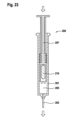
図2~8に示されるシリンジ100の形態での注射デバイスの第1の実施形態は、ハウジング101と、その遠位端に取り付けられた針102とを含む。動作原理を図1によって実例で示す。針102は、ハウジング101内に収容された第1のチャンバ105と流体連通しており、第1のチャンバ105は、第1の薬物成分、例えば凍結乾燥された薬物を含む。
A first embodiment of an injection device in the form of a
プランジャ107は、ハウジング101内で、シリンジ100またはハウジング101に対して軸(長手)方向に可動であり、プランジャ107は、その近位端で第1のチャンバ105を閉じる。
プランジャ107内には、第2の薬物成分、例えば希釈剤を含む第2のチャンバ109が設けられている。第2のチャンバ109は、その遠位端で下側ピストン111によって閉じられ、その近位端で上側ピストン112によって閉じられる。下側ピストン111および上側ピストン112は、プランジャ107内で可動である。プランジャ107は、スリーブ状の要素として形成され、第1のチャンバ105の近位端での第1のチャンバの密封シールが、遠位端セクション108によって提供され、遠位端セクション108は、プランジャの残りのセクション(ハンドル113を除く)よりも大きい直径を有する。遠位端セクション108の直径は、第1のチャンバ105の内径に相当する。プランジャ107の近位端は、ハンドル113として形成されている。プランジャ107の遠位端セクションは、例えば円筒形の貫通穴114を含む。流体の通過を許可することに加え、この貫通穴114は、スタッド状のコッターピン117用のガイドとして作用し、ピストン111が、安定した軸方向運動を確実に行えるようにする。
A
針102は、その遠位端で、針ブーツ115によって覆われている。針ブーツ115は、圧力差により空気がシリンジ100に流入するのを防ぐために必要とされる。
初期位置で、下側ピストン111は、プランジャ107の平坦な内面の領域に位置している間、第1のチャンバ105と第2のチャンバ109との間にシールを形成する。図2において初期状態で示されているシリンジ100の混合および/または再構成プロセスを起動させるために、近位方向ストロークにおいて、ユーザは、ハンドル113を使用して、プランジャ107をシリンジ100から近位方向に引き戻す(図3における、プランジャ107を完全に引き戻した位置を参照)。これにより、シリンジ100、特に第1のチャンバ105の内部に低圧の領域が形成される。プランジャ107がさらに引き戻されるにつれて、圧力はさらに低下する。プランジャ107は、プランジャ107とハウジング101との間のラチェットシステム(図8参照)によって、図2に示されるその元の位置に戻るのを妨げられる。プランジャ107からの外側突出部は、ハウジング101のトラック内に延びる。この突出部は弾かれて、トラック内のラチェット101aと係合し、したがって、プランジャ107は、その移動が完全に完了するまで、一方向にのみ移動することができる:その後、突起は、滑らかなリターントラック(return track)101b内に案内される。ラチェット101aを有するラチェットシステムは、プランジャ107がシリンジ100から十分に引き出されてからリターントラック101bに沿ってシリンジ100内に戻り始めることを確実にし、それによって、最低レベルの吸引力が発生されることを保証する(図3参照)。低圧によって提供される吸引力は、貫通穴114を通してプランジャ107内に第1の薬物成分を引き込むために必要とされ、また第1のチャンバ105内での第1の薬物成分と第2の薬物成分との混合を促進するためにも必要とされる。
In the initial position, the
シリンジの内部、特に第1のチャンバ105および第2のチャンバ109の内部と大気との圧力差により、下側ピストン111に対する力が生じる。この力は、第2のチャンバ109内に含まれている第2の薬物成分を介して上側ピストン112に伝達される。それにより、下側ピストン111および上側ピストン112は、プランジャ107を下に移動させる。それにより、コッターピン117は、上側ピストン112が下側ピストン111に当たるまで、貫通穴114および下側ピストン111を通って移動する(図3参照)。コッターピン117および/または下側ピストン111は圧縮可能な外面を含み、圧縮可能な外面は、平坦でない内面を形成するプランジャ107の内面の遠位端に設けられた1組の長手方向リブ120(ウェブ状要素)と相互作用する(図7参照)。下側ピストン111が平坦でない領域(リブ)に押し込まれると、シールが破られる。これらのリブ120は、下側ピストン111の周りに強制的に隙間を空け、流体が通過することができ、したがって、貫通穴114を通して、第2のチャンバ109に含まれている第2の薬物成分と第1のチャンバ105に含まれている第1の薬物成分との間の流体連通経路を開く。第2の薬物成分は、プランジャ107の遠位端からシリンジ100の第1のチャンバ105内に流れる(図4参照。図4は、第2の薬物成分がすべて第1のチャンバ105に注ぎ込んだ位置を示す)。プランジャ107が完全に引き戻される前に、第2の薬物成分はすべて、シリンジ100の第1のチャンバ105に入り込んでいる。プランジャ107が移動してさらに戻るにつれて、チャンバ105内の圧力は真空に近くなるまで低下する。
The pressure difference between the interior of the syringe, particularly the interior of the
プランジャ107が近位方向へのそのストロークを完了すると、ラチェット機構は、シリンジ100内と大気との圧力が平衡するまで、プランジャ107がシリンジ100内に移動して戻ることができるようにする。この戻りは突然であり、急激な平衡により、チャンバ105内での第1の薬物成分と第2の薬物成分との混合が促進される。
Once the
この時点で、混合物の透明度(mix clarity)の目視確認が必要とされ、その後、第1の薬物成分と第2の薬物成分とを含む混合および/または再構成された薬物を注射することができる。薬物が完全には混合されていない場合、ユーザは、デバイスを手動で振って薬物を完全に混合する必要がある。薬物が完全に混合されると、任意の標準的なシリンジと同様に、ハンドル113を用いてプランジャ107を遠位方向に動かすことにより、プランジャ107を使用して薬物を注射することができる(注射後のシリンジ100を示す図6参照)。
At this point, visual confirmation of mix clarity is required, after which the mixed and/or reconstituted drug comprising the first drug component and the second drug component can be injected. . If the drug is not completely mixed, the user must manually shake the device to mix the drug thoroughly. Once the drug is thoroughly mixed,
薬物を注射するためにプランジャ107が移動されるとき、シリンジ100内の圧力上昇により、上側ピストン112および下側ピストン111が近位方向に移動し、上側ピストン112の近位端にあるスナップまたはクリップ部材112aと、プランジャ107の内面にあるスナップまたはクリップ部材107aとが相互作用して機械的にロックする(図5参照。例えばフックおよび突起によって実現される)。これは、シリンジ100内の圧力上昇により、下側ピストン111および上側ピストン112がプランジャ107内にさらに押し戻されることを防ぎ、したがって、第2の薬物、または第1および第2の薬物の混合物が、プランジャ107内に移動して戻ることはあり得ない。この位置では、下側ピストン111は、もはやプランジャのリブ120と相互作用せず、したがって、下側ピストン111は第2のチャンバ109を閉じる。様々な詳細設計構成によっては、これは、上述した突然の圧力平衡中に既に行われている可能性があることに留意されたい。
When
代替実施形態では、ユーザが第1および第2の薬物成分を含む混合物の透明度を目視で確認する時点で、シリンジ100を手動で振る代わりに、再びチャンバ105内に低圧の領域を形成するためにプランジャ107を連続的に引き戻すことが可能にされる。この循環プロセスは、閉ループを形成するラチェット機構によって可能にされ、プランジャ107の機構が繰り返し動作することができる。第1および第2の薬物成分が完全に混合されるまで、ユーザは、好きな回数だけプランジャを引き戻し、解放することができる。
In an alternative embodiment, instead of manually shaking the
さらなる実施形態では、注射デバイスは自動注射器である。この自動注射器は、第1および第2の薬物成分の混合がユーザの介入なしで行われるように、逆方向へのプランジャの自動化された動きを含むように構成される。ユーザが必要と考える限り自動注射器が混合サイクルを続けることができることが必要であるように、第1および第2の薬物成分を含む混合物の透明度を目視で確認することが、依然としてユーザに求められる。これは、上で概説したように、低圧領域を繰り返し形成することを使用して実現される。 In further embodiments, the injection device is an auto-injector. The auto-injector is configured to include automated movement of the plunger in opposite directions such that mixing of the first and second drug components occurs without user intervention. The user is still required to visually check the clarity of the mixture containing the first and second drug components, as is necessary for the auto-injector to be able to continue the mixing cycle for as long as the user deems necessary. This is achieved using repeated formation of low pressure regions as outlined above.
第1のチャンバ105と第2のチャンバ109との間の上記の連通は、下側ピストン111がプランジャ107のリブ120と相互作用するとき、ハウジング101内の下側ピストン111によって提供されるシールを破ることによって提供される。あるいは、第2の薬物成分がピストン111の周りを流れることを可能にするバイパス経路が形成される。さらなる代替として、図1に示されるようなある形態の針/セプタム相互作用を使用することもでき、下側ピストン111の遠位端に取り付けられた針122が、プランジャ107の遠位端セクション108の膜125を穿孔する。
The above communication between the
針102は、交換可能であり、注射デバイスに着脱可能に取付け可能である。
さらなる実施形態では、ラチェット機構は、注射デバイス100の内部にあるのではなく、別個のハウジング内で注射デバイスの外部に収納される。ハウジングは、シリンジ100およびプランジャ107を保持し、ラチェットが実現したのと同様にそれらの相対運動を案内する。これにより、部材100と107との複雑な相互作用がなくなるため、使い捨てデバイス内の空間が節約される。
In a further embodiment, the ratchet mechanism is not internal to the
さらなる実施形態では、上述した軸方向運動の代わりに、標準的なペン型注射器において見られるそれらのシステムと同様に、軸方向運動と回転(ねじれ)運動との複合運動をユーザが行って、プランジャ107を引き戻すことができる。 In a further embodiment, instead of the axial motion described above, the user performs a combined axial and rotational (torsional) motion similar to those systems found in standard pen syringes to move the plunger. 107 can be pulled back.
さらなる実施形態では、注射デバイスにニードルシールドを含むことが可能である。このシールドは、針102を覆い、ユーザが注射のために自分の皮膚にデバイスを押し付けるときに後退する。針102が皮膚から抜かれると、シールドは所定の位置に戻り、それによりロッキング機構を起動させ、ユーザがニードルシールドを再び後退させることはできなくなる。
In further embodiments, the injection device can include a needle shield. This shield covers the
図1~8を参照して説明した上述の実施形態は、プランジャが注射デバイスに自然に跳ね戻るまでユーザがプランジャを引き戻すだけでよく、向上したユーザ操作性を提供するという利点がある。さらに、ラチェット機構がプロセスを調整するため、結果はユーザのスキルに影響されない。さらに、ユーザは、第1および第2の薬物成分の混合物の透明度を目視で確認することができる。ユーザは、残りの第1または第2の薬物成分を確実に完全に混合するために、注射デバイスを静かに振るだけでよい。さらに、再構成プロセス中、空気は導入されない。注射は、患者が知っている標準的な手順と同様である。さらに、すべて工場封止環境(factory-sealed environment)内で行われるため、混合および/または再構成プロセス中の汚染の危険はない。第1および第2の薬物成分の混合は、非常に予測可能であり、一貫性がある。さらに、ユーザは、使い捨て部材を1つだけ有し、使用全体を通して無菌性が維持されるため、どの部材の無菌性も確保する必要はない。第1および第2の薬物成分の混合を促進するために低圧領域を使用するが、この低圧は、デバイスの保管中に保持される必要はない。 The embodiments described above with reference to FIGS. 1-8 have the advantage that the user only has to pull back the plunger until it spontaneously springs back into the injection device, providing improved user operability. Furthermore, since the ratchet mechanism regulates the process, the results are not influenced by the skill of the user. Additionally, the user can visually check the clarity of the mixture of the first and second drug components. The user only needs to gently shake the injection device to ensure thorough mixing of the remaining first or second drug component. Additionally, no air is introduced during the reconstitution process. Injections are similar to standard procedures known to patients. Additionally, there is no risk of contamination during the mixing and/or reconstitution process since everything is done within a factory-sealed environment. The mixing of the first and second drug components is highly predictable and consistent. Furthermore, the user does not have to ensure the sterility of any of the parts since he only has one disposable part and sterility is maintained throughout use. Although a low pressure region is used to facilitate mixing of the first and second drug components, this low pressure need not be maintained during storage of the device.
図10~15に示され、図9に概念図として示されている実施形態は、ハウジング501を有するシリンジ500と、シリンジ500の遠位端に取り付けられた針502とを含む。針502は、シリンジ500のハウジング501内に収容された第1のチャンバ505と流体連通している。第1のチャンバ505は、その近位端でプランジャ507によって画成される。第1のチャンバ505は、第1の薬物成分、例えば凍結乾燥された薬物を含む。針502は、患者への薬物の注射に適している。最小体積の空気が、第1のチャンバ505内で第1の薬物成分と共に保持される。
The embodiment shown in FIGS. 10-15 and conceptually shown in FIG. 9 includes a
さらに、ハウジング510a(カスタムハウジング)を含む一次パッケージ510が提供される。一次パッケージ510は、そのハウジング510aによって形成された第2のチャンバ509内で、下側ピストン511と上側ピストン512との間に収容された第2の薬物成分、例えば希釈剤を含む。下側ピストン511と上側ピストン512とはどちらも、一次パッケージのハウジング510a内で軸方向に可動であり、下側ピストン511は、上側ピストン512よりも近位に収容される。下側ピストン511は、その本体内にセプタムシールを含む。さらに、下側ピストン511は、その上面または遠位面に、凹部または窪み511aを含む。上側ピストン512は、その遠位側で、駆動機構としての圧縮ばね530と接触し、圧縮ばね530は、最初は圧縮されており、クリップ機構536によって所定の位置に保持されている。一次パッケージ510の遠位端のキャップ535は、クリップ機構536を覆って位置し、すなわち、キャップは、クリップ機構536とばね530とを覆う。キャップ535は、例えば近位方向へ下方向に押されるとき、クリップ機構536を解放し、ばね530が上側ピストン512に近位方向への軸方向力を加えることを可能にする。一次パッケージ510の近位端には、取付け手段、例えばルアーロック537の一部が設けられる。図10に示されるように、混合および/または再構成プロセスの起動前に、一次パッケージ510は、取付け手段、例えばルアーロック537によってシリンジ500の遠位端に取り付けられる。このルアーロック537は、針502の露出部分が注射まで無菌のままであることを保証するためのシールを提供し、例えば、針502の周囲の空間が、デバイスの組立て中に封止され、注射の直前までそのように維持される。さらに、一次パッケージ510のハウジング510aおよびルアーロック537と接触するOリング538が提供され、追加のシールを形成する。
Additionally, a
ルアーロックではなく、シリンジ500と一次パッケージ510との別の取付け手段を使用することもできる。取付け機構は、1年間の保管期間にわたって安全な状態を維持し、さらに、手で簡単に係合および係合解除できなければならない。
Other means of attaching the
ルアーロック537によるシリンジ500の遠位端への一次パッケージ510の取付け後の図10に示される初期位置では、針は、下側ピストン511をある程度まで穿孔するが、下側ピストン511の本体内のセプタムシールを貫通しない。
In the initial position shown in FIG. 10 after attachment of the
混合および/または再構成プロセスを開始するために、ユーザはキャップ535を押圧し、近位方向に動かす(図11の矢印540参照)。それにより、圧縮ばね530を保定するクリップ機構536が係合解除され、圧縮ばね530が延伸することを可能にする(図11および12参照)。一実施形態では、係合解除は、以下のように作用する。上側ピストン512は、1つの可撓性クリップまたは2つ以上の可撓性クリップ(図示せず)を含み、可撓性クリップは、ハウジング510aの穴を通過し、ハウジング510aの上面に対して作用する。キャップ535は、対応する可撓性クリップに被さるその前端部に凹部(図示せず)を含む。キャップ535が押し下げられると、クリップは、対応する凹部に入る。各凹部は面取りされているので、クリップが入ると、一緒に圧縮され、クリップをハウジング510aから係合解除し、ばね530が軸方向に延伸できるようになる。延伸したばね530からの力とユーザの手からの力とはどちらも、第2の薬物成分(第2の薬物成分と、上側ピストン512および下側ピストン511と)を含むサブシステムを一次パッケージ510の軸方向近位方向に沿って押すのに寄与することができる。それにより、針502は、下側ピストン511のセプタムシールを貫通させられ、それにより、シリンジ500の第2のチャンバ509と第1のチャンバ505との流体連通を形成する。下側ピストン511は、一次パッケージ510内のエンドストップ構成、例えばハウジング510aの内面にある突出部513によって、さらに移動するのを止められる(図10参照)。この位置では、針502の遠位端は、下側ピストン511の凹部511a内に位置する。上側ピストン512は、近位方向および下側ピストン511の方向にさらに移動させられ、それにより第2のチャンバ509内の圧力を上昇させ、針502を通して第2の薬物成分を第1のチャンバ505に押し込む(図12の矢印541参照)。
To begin the mixing and/or reconstitution process, the user presses on
下側ピストン511にある凹部511aにより、針502は、上側ピストン512に接することなく、下側ピストンを通って突き出すことが可能になる(図11および13参照)。第2の薬物成分の全量が、第2のチャンバ509から第1のチャンバ505に移送されるとき、下側ピストン511と上側ピストン512とが最終的に接することに留意されたい。凹部511aは、上側ピストン512が下側ピストン511に接触する場合、針502が上側ピストン512に接触せず、その結果、針502を通る第2の薬物成分の流れが止まらないという利点を有する。別の実施形態では、同じ効果のために、下側ピストン511ではなく上側ピストン512に凹部が位置する。
A
第2の薬物成分が第1のチャンバ505に入るとき、第2の薬物成分が流体である場合にはかなりの圧力を受け、高速噴流(jet)(例えば、2.5m/秒以上の流体速度で、好ましくは5m/秒以上の速度で)を生成する。この噴流は、第1の薬物成分を押し退け、乱流混合を引き起こす。上側ピストン512が、第2の薬物成分を第1のチャンバ505へ排出し終えるまでに、第2の薬物成分のすべてが第1の薬物成分と混合される。ばね530は、この圧力すべてを発生して、第2の薬物成分を押勢し、ユーザの力またはスキルに関係なく、信頼性が高く反復可能な混合を保証する。ユーザは、第1および第2の薬物成分が完全に混合されていることを目視で確認することができる。
When the second drug component enters the
次いで、ユーザは、シリンジ500から一次パッケージ510を回して外す(図14の矢印542参照)か、または別の方法で取り外すことができる。ここで、シリンジは、第1のチャンバ505内に含まれる混合および/または再構成された薬物を注射する準備が整う(図15参照)。
The user can then unscrew (see
別の実施形態では、第1の薬物成分を収容するために標準的なシリンジ500を使用するのではなく、カートリッジを使用して、注射用の別のデバイスに配置することができる。
In another embodiment, rather than using a
一実施形態では、シリンジ500内のプランジャ507は、流体噴流による混合を改善するためにカスタム成形される。例えば、プランジャ507は、その前端部に、第1のチャンバ505を画成する1つまたはそれ以上の凹形空洞を含む。そのような空洞内では、流体の噴流が偏向されて、第1のチャンバ505の隅により良く貫入する。代替としてまたは追加として、第1のチャンバ505を画成するプランジャ507の前端部にある1つまたはそれ以上のベーンが、同様の効果を実現する。
In one embodiment,
別の実施形態では、シリンジ500内の針502の近位端は、流体の噴流が近位方向に向けられ、乱流混合の大部分を第1の薬物成分の近くに保つように形作られる。例えば、針502の近位端は湾曲部を有し、それにより、噴流が斜めの角度で第1のチャンバ505に入り、渦流をもたらして混合を促進する。代替としてまたは追加として、複数の噴流を生成するために、針502の近位端の側壁に貫通穴が提供される。
In another embodiment, the proximal end of the
さらなる実施形態では、一次パッケージ510は、手動注射が必要ないように自動注射器に収容される。自動注射器は、挿入前に一次パッケージ510の取外しまたは分離を可能にしなければならない。
In a further embodiment,
別の実施形態では、シリンジ500と一次パッケージ510との取付けは、より永続的である。例えば、シリンジ500と一次パッケージ510とは互いに溶接され、溶接は、シール538およびルアーロックコネクタ537の構成の代わりに使用される密封シールを生成する。この場合、機構は、注射前にシリンジ500と一次パッケージ510とが分離できるようにしなければならない。これは、スナップ機構によって実現され、ここで、シリンジ500のハウジング501と一次パッケージ510のハウジング510aとは、ユーザが圧力を加えると簡単にスナップ解除される。
In another embodiment, the attachment of
さらなる実施形態では、一次パッケージ510は2つの個別の部材を含み、一方がばねを保持し、他方が、第2の薬物成分を含む第2のチャンバならびに上側および下側ピストン511、512のみを保持する。これにより、製造中に一次パッケージ510を一緒に溶接する必要がなくなる。部材は、シリンジ500に取り付ける前にインターロック(interlock)しなければならない。
In a further embodiment, the
さらなる代替実施形態では、上側ピストン512を駆動するための力は、上述した圧縮ばね530によってではなく、別の駆動機構、例えばガスばねまたはリニア電気機械アクチュエータによって生成される。
In a further alternative embodiment, the force for driving the
別の実施形態では、特定の第1および第2の薬物成分の効果的な混合に適切な噴流プロファイルを生成するために、第1のチャンバ505および第2のチャンバ509ならびに針ゲージのサイズをカスタマイズすることができる。
In another embodiment, the size of the
針502は、シリンジ500にかしめられる(stake)のではなく、交換可能でよい。この場合、混合および/または再構成に1本の針が使用されるが、ユーザは、それを注射用の別の無菌針に交換する。
さらなる実施形態では、混合および/または再構成プロセスは、キャップ535を押すのではなく、一次パッケージ、例えばそのハウジングの動きによって起動される。例えば、ユーザが一次パッケージ510をシリンジ500に取り付けるとき、下側および上側ピストン511が自動的に駆動され、針502がセプタムを完全に貫通し、第1のチャンバ505への第2の薬物成分の流れを開始する。
In further embodiments, the mixing and/or reconstitution process is activated by movement of the primary package, such as its housing, rather than pushing on the
図9~15に関して上で説明した実施形態の利点は、ユーザがデバイスの遠位端にあるボタンを押して、混合および/または再構成が完了するまで待つだけでよいので、ユーザの利便性が非常に良いことにある。これは、ユーザが目視で確認することができる。次いで、ユーザは、一次パッケージ510からシリンジ500を外し、通常通りにプライミングすることによって空気を排出し、薬物を注射する。すべてが工場封止環境内で行われるので、混合および/または再構成プロセス中の汚染の危険はない。混合は非常に予測可能で一貫性があり、ユーザは、2つの使い捨て部材、すなわち一次パッケージ510およびシリンジ500のみを有する。無菌性は使用全体を通して維持されるので、ユーザはどの部材についても無菌性を確保する必要がない。
An advantage of the embodiments described above with respect to FIGS. 9-15 is that it provides great user convenience, as the user only has to press a button on the distal end of the device and wait until mixing and/or reconstitution is complete. It's a good thing. This can be visually confirmed by the user. The user then removes the
図17~28に記載した実施形態は、シリンジ200の形態での注射デバイスと、ベースステーション250の形態での混合ユニットとを含む。シリンジ200は、第1のチャンバ205を有するハウジング201と、プランジャ207とを含み、プランジャ207は、その近位端で第1のチャンバ205を閉じる。プランジャ207は、その遠位端で、プランジャ207の対応する内部空間内に第2のチャンバ209を形成する。第1のチャンバ205は、第1の薬物成分、例えば希釈剤を含み、第2のチャンバ209は、第2の薬物成分、例えば凍結乾燥された薬物を含む。さらに、磁気特性または常磁性特性を備えた可動スラグ状要素210が、第2のチャンバ209内に提供される。プランジャ207の第2のチャンバ209の遠位端は、シール211によって覆われている。シールは、例えば、アルミニウムポリマーラミネート、または環状オレフィンなどの低透過性ポリマーを含む、またはそれらからなる箔または膜によって実現される。シリンジ200のハウジング201の遠位端には、針カバー215を有する針202が取り付けられる。針202は、シリンジ200の第1のチャンバ205と流体連通している。針カバー215は、針202を保護し、その汚染を避け、ユーザに針が刺さるのを防止する。
The embodiments described in FIGS. 17-28 include an injection device in the form of a
スラグ状要素210は、例えば、好ましくは医療グレードコーティングを伴う焼結されたネオジム-鉄-ホウ素(NdFeB)、サマリウム-コバルト(SmCo)、およびアルミニウム-ニッケル-コバルト(AlNiCo)のうちの少なくとも1つの材料を含む、またはそれらからなる。要素210の中央または主要セクションは、好ましくは円筒体として形成される。あるいは、中央または主要セクションは、バレルまたは球の一部の形状を有する。図24に詳細に示される、この要素210の1つの遠位端210aは、シール211に穿孔するための鋭利な先端として形作られている。さらに、要素210が摺動してプランジャ207内に戻るのを助けるために、要素210の近位端210bはテーパ状であり、したがって、要素210は、プランジャ207とシリンジハウジング201の内壁との間に拘束されて、それにより混合および/または再構成された薬物の完全な注射を妨げることがない。
The slug-
シール211は、弛んだ部分を作らないように破れるように提供される。同様に、針202の近位端を小さくして箔部材が入れないようにし、またはフィルタがシリンジ内部に(例えば、第1のチャンバの遠位端に、または第1のチャンバ205内部に)追加されて、箔部材が針202に入るのを防止する。
ベースステーション250は、一連の電磁コイル260aと、2つの隣接する電磁コイル260aの間に収容されたフライス鋼磁極片260bとを含み、磁束を誘導して効率を向上させる。電磁コイル260aと鋼磁極片260bとが、電磁ユニット260を形成する。電磁ユニット260は、シリンジ200の遠位端を受け入れるために提供された円筒形開口部265を取り囲む。開口部265内の挿入されたシリンジ200は、例えば図17、19、20、および21に示されている。ベースステーション250は、制御ユニット270と、ベースステーション250の構成要素のための電気エネルギーを提供するために電池273を有する電源とをさらに含む。さらに、ボタン275が提供され、シリンジ200が開口部265に挿入されたときに、ボタン275を押すことにより、ユーザによって第1および第2の薬物成分の混合および/または再構成が起動される。ベースステーション250の開口部は、開口部265内へのシリンジ200の正しい完全な挿入を認識するシリンジ200用のセンサを含む。シリンジ200が開口部265内部に正しく挿入されたことをセンサが認識しない場合、ボタン275を起動しても、混合および/または再構成工程が開始されない。
第1の工程では、シリンジ200は、その本体201が開口部265によって完全に受け入れられる(矢印213参照)まで、ベースステーション250の開口部265(図18参照)に挿入される。ボタン275を押すことにより、ユーザは、電磁ユニット260を起動させてコイル260aを励磁し、シリンジ200の軸方向、例えば遠位方向への大きな力が所定の期間中にスラグ状要素210に及ぼされ、それにより、スラグ状要素210がシール211を穿孔する。それにより、第1および第2の薬物成分が第1のチャンバ205内で混合すること、例えば両方の成分を再構成することが可能にされる。
In the first step,
一実施形態では、ベースステーション250は、混合が完了するまで、ベースステーション250の開口部265内にシリンジ200を保持する別個のインターロックシステムを含む。
In one embodiment,
要素210は、シール211に穿孔すると、第1のチャンバ205の全長に沿ってシリンジ200の軸方向で前後に自由に移動できる(矢印214参照)。図20は、シール211を穿孔するためにスラグ状要素210が加速される初期段階に関する、磁束密度を伴う磁束線を示す。磁力線は、参照番号262を付されている。その後、コイル260aと磁気要素210とが、ブラシレスリニアモータ、すなわちローレンツ力デバイスを形成し、それにより、様々なコイルを様々な方向に様々な時点で励磁することにより、所定の期間内に要素210がシリンジ200の軸(長手)方向(矢印214)で前後に移動し、第1のチャンバ205内部での混合を行う(図21参照)。一実施形態では、ベースステーション250は、軸方向(矢印214参照)に沿って並べて収容される4つのコイル260aを含み、常に、2つのコイル260aが他の2つのコイル260aと交互にアクティブである(図20参照)。2つのアクティブなコイル260aは反対方向に励磁され、要素210の2つの磁極と相互作用して軸方向力を生成し、1つの工程において、2つのアクティブなコイルの一方のコイル260aが要素210の一方の磁極に反発し、他方のコイル260が、要素210の他方の磁極を引き付ける。要素210に近いコイル260aを励磁するだけで、システムの効率が改善される。各コイル260aでの正確な電力レベルを設定することによって、要素の速度および位置が正確に制御される。各コイル260aが40オームの抵抗を有する場合、駆動システムは、例えば200Vを供給するブースト電源を含み、ハーフブリッジを介してコイル260aを0.1秒間駆動する。これにより、コイルに1kWが発生し、箔シールに最初に穿孔するのに必要とされる大きな力を発生する。ベースステーション200の制御ユニット270は、均質な再構成または混合された薬物を保証する電磁ユニット260の異なるコイルを励磁する所定数のサイクルを提供する。プロセスの最後に(図22参照)、要素210は、プランジャ207の以前の第2のチャンバ209内の位置に静止し、それにより注射を妨げない。図24に示されるように、要素210は、要素210がプランジャ207に再び入るのを助けるようにテーパ付きの近位端210bを有する。電磁ユニット260に連結された制御ユニット270によって、プランジャ207への要素210の滑らかな摺動が注射中に提供される。
Once the
最後に、図22に示されるように、シリンジ200がベースステーション250から取り外される。第1および第2の薬物成分を含む混合および/または再構成された薬物を注射するために、ユーザは、針カバー215を取り外し、プライミングによってシリンジから空気を排出し、最後に薬物混合物を注射する(図23参照)。
Finally, as shown in FIG. 22,
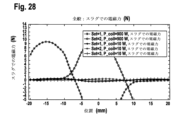
図26および27は、図17に示されている幾何形状に関し、電磁ユニット260の5つの異なるコイルについて、それぞれ10Wおよび900Wで生成される力を示す。10Wでは、力は、第2の薬物成分を押し退け、第1および第2の薬物成分を確実に混合するのに十分である。900Wでは、力は、スラグ状要素210の幾何形状に応じて、要素210が加速されてシール211を穿孔するのに適切である。この高電力は、非常に短い期間、すなわちシール211が穿孔される時間にのみ必要とされ、したがって、使用される総エネルギーは低く、電磁ユニット260のコイルは過熱しない。
26 and 27 show the forces generated at 10 W and 900 W, respectively, for five different coils of
別の実施形態では、例えば鋼を含む軟磁性材料で作られた追加のプレート状金属要素220を使用して、シリンジ200がベースステーション250に配置されて起動されるまで常磁性または磁性要素210を所定の位置に保持し、また注射中に要素210をプランジャ内部に維持することができる。プレート状要素220は、プランジャ207内で、第2のチャンバ209の近位端の近くに収容される(図25参照)。プレート状要素220は、チャンバ209との間の壁をできるだけ薄くすることにより、要素210にできるだけ近接し、好ましくは壁の厚さは1mm未満である。これは、要素220が小さく、それでも要素210に十分な引力を提供することができることを意味する。例えば、要素220は、0.5mmを超える、好ましくは1mmを超える厚さを有する。プレート状要素220は、使用前のデバイスの(例えば)出荷または落下中の意図しない撹拌によりシール211が破れるのを防止する。代替実施形態では、要素220は、ユーザが取り外さなければならない別個の要素、またはベースステーション250へのシリンジ200の挿入時に押し退けられる要素である。例えば、要素は、シリンジ200のハウジング201の外側の周りに収容された鋼カラー部片であり、ベースステーション250への挿入時に摺動されて外される。いずれにせよ、要素220は、電磁ユニット260のコイルが容易に克服することができるほど十分に小さい力を生成する。
In another embodiment, an additional plate-
スラグ状要素210が永久磁石である場合、磁性材料と第1または第2の薬物成分との接触を防ぐために、医療グレードコーティングを使用することが好ましい。
If the slug-
電磁要素210(「ローレンツ力」デバイスまたはリニアブラシレスモータ)に可動磁性材料を使用する代わりに、要素210を軟磁性材料、例えば軟鋼から作ることもできる。この場合、常にコイルを1つだけ起動させればよく、シリンジは、単純な電磁アクチュエータ、例えばソレノイドアクチュエータとして働く。図28に示されるように、そのようなアクチュエータは、所与の電力入力に対してさらに高い瞬時の力を発生するが、これらの力は、第1のチャンバ205内の軟磁性要素の位置に応じてさらに変化し、したがって、力が発生されない要素210の位置を避けるようにコイルを慎重にサイズ設定/配置しなければならない。要素210は、軟磁性材料である場合、例えば医療グレードステンレス鋼であり、この場合、コーティングは必要とされない。その場合、磁気要素210は、箔をより効果的に穿孔するために鋭利な縁部を形成する。
Instead of using a movable magnetic material for the electromagnetic element 210 (a "Lorentz force" device or a linear brushless motor), the
別の実施形態では、単純なシリンジを使用するのではなく、注射デバイスは完全な自動注射器である。上で説明したプロセスは、上述したように行われる:第1および第2の薬物成分を含む第1および第2のチャンバを含む自動注射器がベースステーションに挿入され、成分が混合されて、自動注射器が取り外されて、使用準備が整う。 In another embodiment, rather than using a simple syringe, the injection device is a complete auto-injector. The process described above is performed as described above: an auto-injector containing first and second chambers containing first and second drug components is inserted into the base station, the components are mixed, and the auto-injector is inserted into the base station. is removed and ready for use.
さらなる実施形態として、例えば高価な薬物の場合、別個のベースステーションが必要とされないように、電磁ユニット、電源、および制御ユニットを注射デバイスの使い捨て構成要素に含めることが経済的に妥当である。 As a further embodiment, for example in the case of expensive drugs, it makes economic sense to include the electromagnetic unit, power supply and control unit in a disposable component of the injection device so that a separate base station is not required.
さらなる実施形態では、針202、第1のチャンバ205、およびシリンジ200のハウジング201の内部形状は、混合後に要素210が第1のチャンバ205に残った場合に要素210が注射を妨げないように設計される。
In a further embodiment, the internal geometry of the
シリンジまたは自動注射器ではなく、注射デバイスは、別個の注射デバイスとの使用に適したカートリッジでもよい。言い換えると、この注射デバイスは、シリンジだが、ユーザが注射を実行できるようにする長いプランジャがなく、針もない:この注射デバイスは、皮膚を貫通するためのシステムを含み、注射を駆動するためのシステムも含む。 Rather than a syringe or auto-injector, the injection device may be a cartridge suitable for use with a separate injection device. In other words, this injection device is a syringe, but it does not have a long plunger that allows the user to perform the injection, and there is no needle: this injection device contains a system for penetrating the skin and a system for driving the injection. Including systems.
薬物再構成および/または混合用のシリンジ200およびベースステーション250を含む図16~28に示される本発明のシステムは、すべて工場封止環境内で行われるため、再構成プロセス中に汚染の危険がないので、操作上非常に優れている。シリンジ200を含む使い捨て部材は、非常にコンパクトである。混合/再構成は、少ない工程数で、非常に予測可能であり、一貫性がある。注射ごとに1つだけ使い捨て部材がある。このベースステーションの設計は、注射デバイスの種類、すなわち充填済みシリンジ、自動注射器、およびカートリッジにわたって最大の融通性を提供する。注射デバイスは、再構成に先立って取り付けられる針を必要としない。
The systems of the present invention shown in FIGS. 16-28, including the
図29~32に示される薬物再構成システムの実施形態は、ハウジング301を有するシリンジ300およびバイアル308の形態での充填済み注射デバイスを含む。シリンジ300は、第1の流体薬物成分、例えば希釈剤を含む第1のチャンバ305を含む。バイアル308は、第2の固体および/または流体薬物成分、例えば凍結乾燥された薬物を含む第2のチャンバ309を含む。さらに、システムは、例えば2つの部材310aと310b(図31参照)からなる支持ユニット310を含み、部材310aと310bは、例えばスナップ連結によって互いに解放可能に連結される。シリンジ300はさらに針302に連結され、針302は、針ブーツ315によって覆われている。シリンジ300は、針302に連結されたシリンジ300の遠位端とは反対側のその近位端にプランジャ307をさらに含む。プランジャ307は、シリンジ300の軸(長手)方向に沿ってシリンジ300のハウジング301内で可動である。プランジャ307は、第1のチャンバ305の近位端を閉じる。プランジャ307が近位方向に移動される場合、第1のチャンバ305内に負圧が生成される。プランジャ307が遠位方向に移動される場合、第1の薬物成分は、針302を通して第1のチャンバ305から排出される。
The embodiment of the drug reconstitution system shown in FIGS. 29-32 includes a prefilled injection device in the form of a
薬物再構成システムは、ハウジング351と、ハウジング351内の少なくとも1つの駆動ユニット370とを含むベースステーション350をさらに含む。
The drug reconstitution system further includes a
支持ユニット310は、図31に示される両方の部材310a、310bが互いに連結されるとき、異なる直径を有する2つのセクションを含むカプセルまたは中空円筒体のように形成される(図30参照)。代替として、支持ユニット310の両方の部材310a、310bの連結は、ヒンジ連結である。支持ユニット310は、各部材310a、310bの内側に第1の凹部311および第2の凹部312を形成し、それにより、支持ユニット310は、運送および保管中に充填済みシリンジ300およびバイアル308をロック位置にロックして、それらが互いに接触するのを妨げる。したがって、シリンジ300とバイアル308とが互いに所定の距離を有するように、シリンジ300は第1の凹部311に固定され、バイアル308は第2の凹部312に固定される(図32参照)。例えば、第1の凹部311および第2の凹部312はそれぞれ、その内面に少なくとも1つのウェブまたは同様の突出部を含み、ウェブまたは同様の突出部は、例えばそのネックセクションで、シリンジおよび/または針ブーツ315のハウジング301とのスナップ連結を形成し、またはバイアル308とのスナップ連結を形成する(図32参照)。シリンジ300およびバイアル308が支持ユニット310内に固定され、支持ユニット310の両方の部材310aと310bが互いに連結される場合、自立型アセンブリが形成され、例えば運送および保管中に充填済みシリンジ300およびバイアル308を所定の位置にロックし、それらが互いに接触するのを防ぐ。
The
バイアル308は、ネックのその前端部でバイアル308を覆うシール313を含む。シール313は、第2のチャンバ309を密封して閉じる。
ベースステーション350の駆動ユニット370は、例えば、第1のモータおよび第2のモータを含む。さらに、振動ユニットとして場合により用いられる高周波数トランスデューサ371、さらには場合により用いられるヒータ要素372が、ベースステーション350のハウジング351内に提供される。ベースステーション350は、ハウジング351の上側に凹部365をさらに含み、凹部365は、支持ユニット310内にロックされたときにシリンジ300およびバイアル308を含むアセンブリを受け入れて解放可能に固定するように適用される。したがって、凹部365は、アセンブリの外周に少なくとも部分的に対応する。
薬物を再構成し、注射用のシリンジ300を用意するために、シリンジ310、支持ユニット310、およびバイアル308を含む図32に示されるアセンブリは、ユーザによってベースステーション350の凹部365に挿入され、そこに固定される。ここで、針302を有するシリンジ300およびバイアル308は初期位置にある。ベースステーション350は、図32に示されるアセンブリへの以下のインターフェースを有する:
-バイアル308が静止して保持される;
-シリンジ300は、例えばそのハウジング301で、モータ駆動ユニット370によって軸方向に作動される第1のリニア摺動部(linear slide)374と係合する;
-プランジャ307は、第2の独立したモータ駆動ユニット(図示せず)によって軸方向に作動される第2のリニア摺動部375と係合する。
To reconstitute the drug and prepare the
- the
- the
- The
図32のアセンブリの固定は、次のいずれかによって実現される:
-ユーザがアセンブリを引き出すために克服することができる受動クリップ;または
-別個のモータドライブユニットがクランプ機構を動作させて、再構成プロセス中にアセンブリを所定の位置に保持することができる;または
-図32に示されるアセンブリは、第1および第2のリニア摺動部がそれらの初期位置にあるときにのみ、第1および第2のリニア摺動部と係合/係合解除することができる。
Fixation of the assembly of Figure 32 is achieved by either:
- a passive clip that the user can overcome to pull the assembly; or - a separate motor drive unit can operate a clamping mechanism to hold the assembly in place during the reconfiguration process; or - Figure The assembly shown at 32 can engage/disengage the first and second linear slides only when the first and second linear slides are in their initial positions.
動作中、図32のアセンブリが挿入される位置では、そのアセンブリは、第1および第2のリニア摺動部と位置合わせしたハウジング351のスロットを通過しなければならない。駆動ユニットが移動し始めると、アセンブリの構成は、もはやハウジング351のスロットと位置合わせせず、ユーザがアセンブリを早まって取り外すことは起こり得ない。それにより、アセンブリは、ベースステーション350内で、ある角度で保持され、バイアル308がシリンジ300よりも高く位置決めされ、したがって、準備中に空気ではなくバイアル308の第2のチャンバ309からの第2の成分がシリンジ300に引き込まれる。これは、ベースステーション350が立っている反対側のプラットフォーム面366に対するベースステーション300の凹部365の傾斜角度によって実現される。ベースステーション350は、支持ユニット310の部材をロック解除するための構成を含み、ベースステーション350の凹部365内に位置決めされたときにシリンジハウジング301とバイアル308とが相対的に移動できるようにする。例えば、このロック解除構成は、2つの部材が相対的に移動することができないようにシリンジハウジング301の構成にロックする支持ユニット310内部の可撓性フック要素からなる。凹部365内のピン構成は、支持ユニット310の小さな穴を貫通して、可撓性フック要素を押してずらし、ハウジング301が支持ユニット310に対して移動できるようにする。代替として、固定ピンではなく、このロック解除構成を、例えばソレノイドを用いて能動的に駆動することもできる。アセンブリがベースステーション350から取り外されるとき、構成はロック解除されたままであるはずであり、したがって、ユーザは注射のためにシリンジ300を引き抜くことができる。
In operation, in the inserted position of the assembly of FIG. 32, it must pass through a slot in the
次の工程では、駆動ユニット370の第1のモータが、第1の摺動部374によって、シリンジ300のハウジング301をバイアル308に向けて駆動する。針ブーツ315がバイアル308に対して圧縮され、針302がバイアル308のシール313に挿入され、バイアル308の第2のチャンバ309との流体連結を形成する。針302を有するシリンジ300は、バイアル308に向けて移動され、所定の距離だけ第2のチャンバ309に挿入される。同時に、駆動ユニット370の第2のモータは、第2の摺動部375によってバイアル308に向けて同じ速度でシリンジプランジャ307を移動させ、それにより、第1のチャンバ305内部の体積は、この工程中に変化しない。ここで、バイアル308と、針302を有するシリンジ300とは、起動位置にある。
In the next step, the first motor of the
次の工程では、バイアル308およびシリンジ300の起動位置に達した後、第1のモータが静止して保持された状態で、第2のモータが第2の摺動部375によってバイアル308に向けてシリンジプランジャ307を駆動し、第1の薬物成分、例えば希釈剤をバイアル308の第2のチャンバ309に排出し、第2のチャンバ309内で第1の薬物成分と第2の薬物成分との混合物を形成する。
In the next step, after the
様々な機構を使用して、駆動ユニット370の回転運動をシリンジ300のハウジング301およびプランジャ307への直線作用に変換することができる。図30に示されるユニットは、親ねじを含み、駆動ユニット370のモータは、ねじ山付きバー(threaded bar)を回転させる。ねじ山付きバーに延びるナットがあり、ねじ山付きバーは、シリンジ300のハウジング301と係合する第1のリニア摺動部374に回転不能および軸方向に固定される。ねじ山付きバーが回転されると、ナットがねじ山付きバーに沿って駆動され、ハウジング301を軸方向に駆動する。同じことが、プランジャ307に連結された第2のリニア摺動部375によって提供される。代替として、ねじ山付きバーは、ハウジング301またはプランジャ307と係合するプロファイル付き構成要素(profiled component)に回転不能および軸方向に固定することができ、ナットは、モータによって回転可能に駆動される。このナットは、モータ自体の一部分を形成することができる。
Various mechanisms can be used to convert rotational movement of
第1の流体薬物成分がすべて第2のチャンバ309に移送されると、トランスデューサ371は、第1の薬物成分と第2の薬物成分との混合物を含むバイアル308を撹拌し、例えば薬物粉末と希釈剤との混合を促進する。このトランスデューサ371は、圧電トランスデューサ、すなわち2つの電極間の圧電セラミック片である。振動電圧が電極に印加される場合、トランスデューサの厚さが振動し、圧力波を発生する。圧電トランスデューサの変位が本質的に小さいため、トランスデューサ371とバイアル308との非常に良好な音響連結が必要である。これは、少なくともトランスデューサとバイアルとのばね式の接触、または液体もしくはゲルベースの連結を必要とする可能性がある。代替として、トランスデューサ371は、ボイスコイルまたはソレノイドなどの電磁リニアアクチュエータである。これはより低い周波数で動作するが、より大きな実現可能な変位は、撹拌を混合物に伝達することがより簡単であることを意味する。代替として、不均衡な負荷を駆動するモータ(振動モータ)を使用して、振動する圧力波を発生することもできる。同時に、またはその後、ヒータ要素372は、混合物を事前設定温度(例えば18℃~26℃の範囲内)まで加熱して、患者への薬物注射中に冷たい混合物が不快感を引き起こす可能性を低減する。ヒータ要素372は、電流が通過するときに熱を発生する単純な抵抗要素である。サーミスタ(温度測定センサ)は、いかなる障害によっても過熱が生じることが物理的にあり得ないようにシステムが設計されていない限り、過熱されないことを保証する必要がある。代替として、固体状態ヒートポンプ、すなわちペルチェ素子によって熱を供給することができる。
Once all of the first fluid drug component has been transferred to the
第2の薬物成分が第1の薬物成分に完全に溶解されて、もしくは第1の薬物成分が第2の薬物成分に完全に溶解されて再構成物を形成したとき、または両方の成分が混合されて、(該当する場合には)再構成物または混合物が適正な温度に達したとき、第2のモータは、第2の摺動部375によってシリンジプランジャ307を軸方向に駆動して、バイアル308から離し、混合物または再構成物をシリンジ300に引き込み、すなわちバイアル308の第2のチャンバ309からシリンジ300の第1のチャンバ305に引き込む。バイアル308がシリンジ300よりも高く位置決めされ、針302がバイアル308の最低点にあるので、ベースステーションは、第2のチャンバ309の混合物または再構成物のみがシリンジ300に引き込まれ、シリンジ300内の空気体積を確実に最小限に抑えられるようにする。次の工程では、駆動ユニット370の第1のモータと第2のモータとが共同で作用して、シリンジ300、およびそれと共に針302をバイアル308から引き出す。次いで、ユーザは、シリンジ300をベースステーション350の凹部365から取り出し、支持ユニット310をシリンジから取り外し、シリンジ300の第1のチャンバ305に含まれる再構成または混合された薬物を手動で注射する。バイアル308は使い捨てデバイスであり、シリンジ300は使い捨てまたは再利用可能なデバイスである。
When the second drug component is completely dissolved in the first drug component or the first drug component is completely dissolved in the second drug component to form a reconstituted product, or both components are mixed. and when the reconstitute or mixture (if applicable) has reached the proper temperature, the second motor drives the
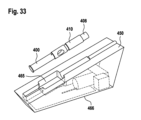
図33~37に示される薬物混合または再構成システムの実施形態は、図29~32に示される実施形態と同様であるが、シリンジ300の代わりに自動注射器400を含む。参照番号の最後の2桁が同じであるが先頭の数字が3ではなく4であるシステムのこの実施形態の要素は、図29~32に示されるシステムのそれぞれの要素に対応する。
The embodiment of the drug mixing or reconstitution system shown in FIGS. 33-37 is similar to the embodiment shown in FIGS. 29-32, but includes an auto-
自動注射器400は、従来のばね駆動設計、または流体、例えば空気圧によって作動されるものである。以下では、最初は空気チャンバ414内の大気圧でユーザに提供される空気圧によって作動される自動注射器400によって本発明を説明する。本発明は、薬物送達エネルギー源としてばねを使用する自動注射器で同様に機能する。
Auto-
薬物再構成システムは、自動注射器400、バイアル408、および支持ユニット410を含み、支持ユニット410は2つの部材410aおよび410bを含み、2つの部材410aおよび410bは、相互に連結し、自動注射器400およびバイアル408を中で固定して、互いに所定の距離または相対位置で運送および保管するためのアセンブリを形成する。さらに、ベースステーション450が提供される。
The drug reconstitution system includes an auto-
自動注射器400は、第1のチャンバ405および針402をさらに含む。第1のチャンバ405は、第1の薬物成分、例えば希釈剤を含む。バイアル408は、第2の薬物成分、例えば凍結乾燥された薬物を含む第2のチャンバ409と、バイアルを覆い、その第2のチャンバ409を密封して閉じるシール413とを含む。システムは、針ブーツ415をさらに含む。
Auto-
自動注射器400およびバイアル408の第1および第2の薬物成分の再構成または混合のために、針ブーツ415は、図36に示されるように、支持ユニット410の第1の凹部411に取り付けられる。次いで、支持ユニット410の第1および第2の部材410a、410bを互いに連結し、バイアル408および自動注射器400をそれらのそれぞれの第1および第2の凹部411、412に挿入することによって、アセンブリが構成される。支持ユニット410への自動注射器400の取付けのために、自動注射器400の針ガード417を後退させて、針402を露出させなければならず、次いで、針402が針ブーツ415によって覆われる(図35参照)。自動注射器400およびバイアル408は、例えばスナップ連結によって支持ユニット410に固定される。
For reconstitution or mixing of the first and second drug components of auto-
図33~37に示されるシステムを用いて薬物を再構成するために、アセンブリ(図35参照)は、図33に示されるように、ベースステーション450の凹部465に挿入される。ここで、自動注射器400およびバイアル408は初期位置にある。ベースステーション450の構成が、支持ユニット410の部材410a、410bをロック解除し、針ブーツ415を有する自動注射器400とバイアル408とが、駆動ユニット470に連結された第1の摺動部によって、自動注射器400の軸方向に沿って互いに向けて移動できるようにする。例えば、ロック解除構成は、支持ユニット410の内面から突出する可撓性フック要素からなり、可撓性フック要素は、自動注射器ハウジング401の外面の対応する凹部にロックし、その結果、支持ユニット410と自動注射器ハウジング401とは相対的に移動することができない。凹部465内のピン構成は、凹部465内のベースステーション450に正しく取り付けられるとき、支持ユニット410の小さな貫通穴を貫通し、可撓性フック要素を押してずらし、自動注射器ハウジング401が支持ユニット410に対して移動できるようにする。代替として、固定ピンではなく、このロック解除構成を、例えばソレノイドまたは第2の駆動モータを用いて能動的に駆動することもできる。代替として、支持ユニット410内部の解放機構を起動させるのではなく、ロック解除構成は、支持ユニット410を完全に開く、すなわち自動注射器ハウジングの2つの部材410a、410bを分離することができる。ロック解除構成は、アセンブリがベースステーション450から取り外されたときにロック解除されたままであるはずであり、したがってユーザが注射のためにシリンジ400を引き抜くことができる。
To reconstitute the drug using the system shown in FIGS. 33-37, the assembly (see FIG. 35) is inserted into the
次の工程では、ベースステーション450の針が、自動注射器本体401のセプタム418を穿孔し、ベースステーション450の空気ポンプ473が、プランジャ407を含む自動注射器の空気チャンバ414に空気を出し入れすることができるようにする。針は、空気ポンプ473に流体連結される。次いで、ベースステーション450の駆動ユニット470の第1のモータが、自動注射器400をバイアル408に向けて押す。それにより、針ガード417はさらに自動注射器本体401内に後退し、針ブーツ415は圧縮され、したがって、針402は、例えばゴムキャップとして形成されたシール413を介して、バイアル408、例えばその第2のチャンバ409内に挿入される。駆動ユニット470と連結された第1の摺動部は、ハウジング401の構成と係合し、それを軸方向に駆動する。様々な機構を使用して、駆動ユニットモータの回転運動を自動注射器本体401の直線作用に変換することができる。図37に示される機構は、親ねじであり、モータがねじ山付きバーを回転させる。ねじ山付きバーに延びるナットがあり、ねじ山付きバーは、自動注射器本体401と係合する第1のリニア摺動部(例えば、プロファイル付き構成要素)に回転不能および軸方向に固定される。ねじ山付きバーが回転されるとき、摺動部は、ねじ山付きバーに沿って駆動され、自動注射器本体401をバイアル408に向けて軸方向に駆動し、それにより針402を第2のチャンバ409に挿入する。このとき、自動注射器400およびバイアル408は起動位置にある。
In the next step, the needle at
その後、ベースステーション450の駆動ユニット470の第2のモータは、自動注射器400の機構を起動させて、自動注射器400のプランジャ407をロック解除し、プランジャ407がプランジャロッキング機構420を使用して移動できるようにする。ロッキング機構420は、自動注射器400が充填されてプライミングされた後、ユーザによって起動されるまで、その蓄積されたエネルギーを解放して薬物を注射しないように存在する。ロッキング機構420は、図35では単純なロッキングピンとして示されているが、プランジャを所定の位置にロックする任意のキャッチ構成でよい。このキャッチは、薬物送達を開始するために後で解放され、例えば、ユーザがボタンを押してキャッチを動かしてプランジャから離し、または針ガードが皮膚に押し付けられるときにキャッチが解放される。しかし、キャッチは、ベースステーション450が自動注射器400の混合およびプライミングを行うことができるように、ベースステーション450によっても操作されなければならない。したがって、駆動ユニット470の第2のモータは、例えばロッキング機構420のキャッチを解放することによって、自動注射器プランジャ407を解放する。次いで、ベースステーション450の空気ポンプ473は、駆動ユニット470によって駆動されて、セプタム418を穿孔する針を介して、プランジャ407を取り囲む空気チャンバ414に空気を送り込み、それにより、プランジャ407をバイアル408に向けて押し、同時に第1のチャンバ405から第1の薬物成分を排出する。したがって、ここで、第1のチャンバ405の第1の薬物成分は、バイアル408の第2のチャンバ409内の第2の薬物成分と混合および/または再構成することができる。
The second motor of the
混合および/または再構成のために、ベースステーション450は、トランスデューサ471(振動ユニット)を使用してバイアル408を高周波数で振動させ、および/または同時に、ヒータ要素472を使用してバイアル408内の混合物を加温する。混合物または再構成物が調製されると、ベースステーション450の空気ポンプ473は逆に動作して、空気チャンバ414から空気を送り出し、真空を生成して、プランジャ407をバイアル408から引き離し、それにより、薬物混合物または再構成物が自動注射器400の第1のチャンバ405に引き込まれる。次の工程では、駆動ユニット470の第2のモータが、プランジャロッキング機構420を起動させて、プランジャ407を所定の位置に再びロックする。次に、空気ポンプ473は、ここでは薬物送達動力源として、圧縮空気を空気チャンバ414に送り込む。次いで、第1のモータが自動注射器400をバイアル408から引き出し、ユーザがアセンブリ410をベースステーション450から取り外せるようにする。
For mixing and/or reconstitution, the
自動注射器400を使用するために、ユーザは、2つの部材410a、410bを開くことによって、バイアル408および支持ユニット410を引っ張って取り外す。これはまた、同じ工程で自動注射器400から針ブーツ415を取り外す。針ブーツ415の取外しは、針ブーツ415から患者にゴム片を注射する可能性をなくすというさらなる利点を有する。また、この工程は、針ガード417を露呈させる(図36参照)。次いで、ユーザは、針ガード417を注射部位に押し付け、針ガード417を自動注射器本体401に押し込み、針402を患者に挿入する。針ガード417の構成は、自動注射器400の機構を起動させて、プランジャ407をロック解除する。ロック解除機構の一実施形態では、ロッキング機構420に向かう針ガード417の軸方向延在部が存在する。針ガード417がハウジング401内に押し戻されるとき、この延在部は、ロッキング機構420の傾斜または同様の嵌合構成に係合し、ロッキング機構420をプランジャ407から外れるように移動させる、または他の方法でロッキング機構を係合解除する。次いで、プランジャ407は、空気圧を受けて針402に向かって移動し、それにより、患者への混合物または再構成物の注射を提供する。注射が終了されると、ユーザは自動注射器400を注射部位から取り外し、針ガード417は、ばね419のばね力を受けて外方向に延びて、針402を再び覆う。針ガード417はまた、それ自体を自動注射器本体401に対してロックして、針402による刺傷を防止する。
To use auto-
空気圧によって作動される上述した自動注射器の概念の代替実施形態では、薬物送達エネルギー源としてばねを使用する自動注射器の概念を使用することができる。本発明の方法は、混合および/または再構成段階中に、駆動ユニット470の第2のモータがプランジャ407を作動させて第1の薬物成分をバイアル408の第2のチャンバ409内に排出することを除いて、基本的に同じである。混合または再構成後、第2のモータがプランジャ407を引き出し、第1のチャンバ405内に負圧を生成し、混合または再構成された薬物を自動注射器400、すなわちその第1のチャンバ405に引き込む。この動きの完了は、プランジャ407が近位端でそのロッキング位置に達したときに起こり、この作用は送達ばねを圧縮し、同時に薬物送達の準備ができる。起動は、上記の実施形態と同様に行われ、ユーザが針ガード417を注射部位に押し当て、針ガード417を自動注射器本体401に押し込み、針402を患者に挿入し、プランジャ407をロック解除し、ばねがプランジャ407を下向きに駆動して、第1のチャンバ405から薬物を排出できるようにする。上記の例は、薬物を自動注射器400内に引き戻すときに送達ばねを圧縮することを述べているが、製造中にばねを圧縮することも可能である。
In an alternative embodiment of the pneumatically actuated auto-injector concept described above, an auto-injector concept that uses a spring as the drug delivery energy source can be used. The method of the present invention provides that during the mixing and/or reconstitution phase, the second motor of the
さらなる代替実施形態では、第1の薬物成分および第2の薬物成分を含む混合物は、自動注射器またはシリンジの第1のチャンバ305、405とバイアル308、408の第2のチャンバ309、409との間で前後に移送することができる。それにより、それぞれの針302、402は、好ましくは、移送中にウォータージェットを生成し、混合または再構成を促進する。
In a further alternative embodiment, the mixture comprising the first drug component and the second drug component is placed between the
ユーザは、混合または再構成された薬物を注射する前に、シリンジ300を手動でプライミングすることができる。別の実施形態では、シリンジ300を手動でプライミングするのではなく、ベースステーションに、シリンジ300をプライミングするための対応する構成を設けることができる。これは、例えば、第2の駆動機構を使用することによって行うことができ、第2の駆動機構は、ハウジング301を静止して保持しながらプランジャ307を軸方向にわずかな距離だけ移動させ、それによりシリンジ内の空気が排出される。同じことが自動注射器400にも当てはまり、自動注射器は、空気圧または従来の機械的ばねのいずれかによって動力供給される。
A user can manually
ベースステーション350、450、シリンジ300または自動注射器400、支持ユニット310、410、およびバイアル308、408を含む上記の本発明による薬物再構成システムの主な利点は、再構成操作を自動化し、それによりすべての手動工程をなくすことである。トランスデューサ371、471がベースステーション350、450に提供される場合、再構成の一貫性および再現性を改善する。このシステムは、さらに、ユーザに提示されるデバイスの数を減少し、薬物バイアル308、408を消毒する必要をなくす。さらに、患者に空気を注射する可能性を低減する。使用直前にベースステーション450が自動注射器400をプライミングする自動注射器バージョンに関しては、自動注射器400をストレスなく保管および輸送でき、自動注射器400の複雑さならびに不発(misfire)および故障のリスクを低減するという利点がある。
The main advantage of the drug reconstitution system according to the invention described above, which includes a
100、200、300、500 シリンジ
101、201、301、351、501、510a ハウジング
101a ラチェット
101b リターントラック
102、202、302、402、502 針
105、205、305、405、505 第1のチャンバ
107、207、307、407、507 プランジャ
107a クリップ部材
108 遠位端セクション
109、209、309、409、509 第2のチャンバ
111、511 下側ピストン
112、512 上側ピストン
112a クリップ部材
113 ハンドル
114 貫通穴
115、315、415 針ブーツ
117 コッターピン
120 リブ
122 針
125 膜
210 スラグ状要素
210a 遠位端
210b 近位端
211、313、413 シール
213 矢印
214 矢印
215 針カバー
220 要素
250、350、450 ベースステーション
260 電磁ユニット
260a 電磁コイル
260b 鋼磁極片
262 磁力線
265 開口部
270 制御ユニット
275 ボタン
308、408 バイアル
310、410 支持ユニット
310a、310b、410a、410b 支持ユニットの一部分
311、411 第1の凹部
312、412 第2の凹部
365、465、511a 凹部
366、466 プラットフォーム面
370、470 駆動ユニット
371、471 トランスデューサ
372、472 ヒータ要素
374 第1のリニア摺動部
375 第2のリニア摺動部
400 自動注射器
401 自動注射器本体
414 空気チャンバ
417 針ガード
418 セプタム
419 ばね
420 ロッキング機構
473 空気ポンプ
513 突出部
530 圧縮ばね
535 キャップ
536 クリップ機構
538 Oリング
540、541、542 矢印
100, 200, 300, 500 Syringe 101, 201, 301, 351, 501, 510a Housing 101a Ratchet 101b Return track 102, 202, 302, 402, 502 Needle 105, 205, 305, 405, 505 First chamber 107, 207, 307, 407, 507 plunger 107a clip member 108 distal end section 109, 209, 309, 409, 509 second chamber 111, 511 lower piston 112, 512 upper piston 112a clip member 113 handle 114 through hole 115, 315, 415 needle boots 117 cottal pin 120 rib 120 rib 1222225 film 210 slag -like element 210A distal end 210B short edge 211, 313, 413 seal 213 arrows 213 arrows 214 Arrows 215 Hand cover 220, 450 Base Station 260 Electromagnetic Stations 260 260a Electromagnetic coil 260b Steel pole piece 262 Magnetic field lines 265 Opening 270 Control unit 275 Button 308, 408 Vial 310, 410 Support unit 310a, 310b, 410a, 410b Part of support unit 311, 411 First recess 312, 412 Second Recess 365, 465, 511a Recess 366, 466 Platform surface 370, 470 Drive unit 371, 471 Transducer 372, 472 Heater element 374 First linear sliding part 375 Second linear sliding part 400 Auto-injector 401 Auto-injector body 414 Air chamber 417 Needle guard 418 Septum 419 Spring 420 Locking mechanism 473 Air pump 513 Projection 530 Compression spring 535 Cap 536 Clip mechanism 538 O-ring 540, 541, 542 Arrow
Claims (21)
デバイス(300、400)は、第1のチャンバ(305、405)内に第1の材料を含み、ハウジング(301、401)およびプランジャ(307、407)を含み、
バイアル(308、408)は、第2のチャンバ(309、409)内に第2の材料を含み、第1の材料および第2の材料の少なくとも1つは流体であり、
自立型アセンブリは、スリーブ状の支持ユニット(310、410)によって形成され、デバイス(300、400)、バイアル(308、408)、および針(302、402)をさらに含み、
支持ユニット(310、410)は、デバイス(300、400)とバイアル(308、408)とを所定の相対位置に固定するように適用され、針(302、402)は、デバイス(300、400)に取り付けられ、デバイス(300、400)の第1のチャンバ(305、405)と流体連結され、
ベースステーション(350、450)は、少なくとも1つの駆動ユニット(370、470)、第1の摺動部(374)、および駆動部を含み、
該ベースステーション(350、450)は、該デバイス(300、400)、該バイアル(308、408)、および該針(302、402)が初期位置でベースステーション(350、450)に取付け可能であるように適用され、初期位置で、デバイス(300、400)、バイアル(308、408)、および針(302、402)は互いに所定の距離を有し、
初期位置で、少なくとも1つの駆動ユニット(370、470)は、バイアル(308、408)および/またはデバイス(300、400)のハウジング(301、401)をデバイス(300、400)の軸方向で所定の距離に沿って起動位置に相対的に移動させる第1の摺動部(374)に連結され、起動位置で、針(302、402)は第2のチャンバ(309、409)と流体連結され、
起動位置で、少なくとも1つの駆動ユニット(370、470)は駆動部に連結され、
該駆動部は、針(302、402)と第2のチャンバ(309、409)との流体連結中、第1の材料がデバイスの第1のチャンバ(305、405)からバイアル(308、408)の第2のチャンバ(309、409)内に排出されるように、または第2の材料がバイアル(308、408)の第2のチャンバ(309、409)からデバイス(300、400)の第1のチャンバ(305、405)内に排出されるように、プランジャ(307、407)を所定の距離に沿ってデバイス(300、400)の軸方向に移動させ、
自立型アセンブリは、デバイス(300、400)およびバイアル(308、408)の初期位置でベースステーション(350、450)に取付け可能であり、
ベースステーション(350、450)は、ハウジング(351)およびそのハウジング(351)の上側に凹部(365、465)を含み、該凹部は、デバイス(300、400)およびバイアル(308、408)が支持ユニット(310、410)内にロックされたときにデバイス(300、400)およびバイアル(308、408)を含む自立型アセンブリを受け入れて解放可能に固定するように適用され、
ベースステーション(350、450)は、自立型アセンブリがベースステーション(350、450)のハウジング(351)の凹部(365、465)に受け入れられて解放可能に固定され、支持ユニット(310、410)が、ベースステーション(350、450)の凹部(365、465)内に位置決めされたときに、支持ユニット(310、410)の部材(310a、310b、410a、410b)をロック解除して、デバイス(300、400)のハウジング(301、401)とバイアル(308、408)とが相対的に移動できるようにする構成を含むことを特徴とする、前記ベースステーション。 A base station (350, 450) for a mixing and/or reconstitution system, the mixing and/or reconstitution system comprising: a base station (350, 450), a device (300, 400), a vial (308, 408), a needle (302, 402), and a sleeve-like support unit (310, 410);
The device (300, 400) includes a first material within a first chamber (305, 405) and includes a housing (301, 401) and a plunger (307, 407);
the vial (308, 408) contains a second material within a second chamber (309, 409), at least one of the first material and the second material being a fluid;
The self-supporting assembly is formed by a sleeve-like support unit (310, 410) and further includes a device (300, 400), a vial (308, 408), and a needle (302, 402);
The support unit (310, 410) is adapted to fix the device (300, 400) and the vial (308, 408) in a predetermined relative position, and the needle (302, 402) attached to and in fluid communication with a first chamber (305, 405) of the device (300, 400);
The base station (350, 450) includes at least one drive unit (370, 470), a first sliding part (374), and a drive part,
The base station (350, 450) is attachable to the base station (350, 450) with the device (300, 400), the vial (308, 408), and the needle (302, 402) in an initial position. in the initial position, the device (300, 400), the vial (308, 408), and the needle (302, 402) have a predetermined distance from each other;
In the initial position, the at least one drive unit (370, 470) positions the vial (308, 408) and/or the housing (301, 401) of the device (300, 400) in the axial direction of the device (300, 400). the needle (302, 402) is in fluid communication with the second chamber (309, 409) in the actuation position. ,
In the activation position, at least one drive unit (370, 470) is coupled to the drive;
The drive is configured to transfer the first material from the first chamber (305, 405) of the device to the vial (308, 408) during fluidic connection between the needle (302, 402) and the second chamber (309, 409). or from the second chamber (309, 409) of the vial (308, 408) into the first chamber (300, 400) of the device (300, 400). moving the plunger (307, 407) along a predetermined distance in the axial direction of the device (300, 400) such that the plunger (307, 407) is ejected into the chamber (305, 405);
The free-standing assembly is attachable to the base station (350, 450) at the initial location of the device (300, 400) and the vial (308, 408);
The base station (350, 450) includes a housing (351) and a recess (365, 465) in the upper side of the housing (351) in which the device (300, 400) and the vial (308, 408) are supported. adapted to receive and releasably secure a free-standing assembly including a device (300, 400) and a vial (308, 408) when locked within the unit (310, 410);
The base station (350, 450) is releasably secured with a free-standing assembly received in a recess (365, 465) in a housing (351) of the base station (350, 450), and a support unit (310, 410). , unlocking the members (310a, 310b, 410a, 410b) of the support unit (310, 410) when positioned within the recess (365, 465) of the base station (350, 450) , 400) and the vial (308, 408) are movable relative to each other.
該ベースステーション(350、450)は、該自立型アセンブリが起動位置にある場合、第1および/または第2のチャンバ(305、405、309、409)を加熱するように適用されたヒータ要素(372、472)を含む、
請求項1に記載のベースステーション。 The base station (350, 450) is adapted to transmit mechanical vibrations to a vial (308, 408) or device (300, 400) of the free-standing assembly when the free-standing assembly is in an activated position. the base station (350, 450) comprises a first and/or second chamber (305, 405, 309) when the freestanding assembly is in the activated position; , 409);
The base station according to claim 1.
第1の材料を第1のチャンバ(305、405)内に含み、ハウジング(301、401)およびプランジャ(307、407)をさらに含む、デバイス(300、400)と、
第2の材料を第2のチャンバ(309、409)内に含み、第1の材料および第2の材料の少なくとも1つは流体である、バイアル(308、408)と、
請求項1~4のいずれか1項に記載のベースステーション(350、450)と、
針(302、402)と、
を含み、
ここで、デバイス(300、400)とバイアル(308、408)とは、互いに所定の距離を有する初期位置でベースステーション(350、450)に取付け可能であり、針(302、402)は、デバイス(300、400)に取り付けられ、デバイス(300、400)の第1のチャンバ(305、405)と流体連結され、
初期位置で、少なくとも1つの駆動ユニット(370、470)は、デバイス(300、400)のバイアル(308、408)および/またはハウジング(301、401)をデバイス(300、400)の軸方向で所定の距離に沿って起動位置に相対的に移動させる第1の摺動部(374)に連結され、起動位置で、針(302、402)は、第2のチャンバ(309、409)と流体連結され、 起動位置で、少なくとも1つの駆動ユニット(370、470)は駆動部に連結され、該駆動部は、針(302、402)と第2のチャンバ(309、409)との流体連結中、第1の材料がデバイスの第1のチャンバ(305、405)からバイアル(308、408)の第2のチャンバ(309、409)内に排出されるように、または第2の材料がバイアル(308、408)の第2のチャンバ(309、409)からデバイス(300、400)の第1のチャンバ(305、405)内に排出されるように、プランジャ(307、407)を所定の距離に沿ってデバイス(300、400)の軸方向に移動させ、
該混合および/または再構成システムはさらに、デバイス(300、400)、バイアル(308、408)、および針(302、402)をさらに含む自立型アセンブリを形成するように適用されたスリーブ状の支持ユニット(310、410)を含み、支持ユニット(310、410)は、デバイス(300、400)とバイアル(308、408)とを所定の相対位置に固定するように適用され、針(302、402)は、デバイス(300、400)に取り付けられ、デバイス(300、400)の第1のチャンバ(305、405)と流体連結され、自立型アセンブリは、デバイス(300、400)およびバイアル(308、408)の初期位置でベースステーション(350、450)に取付け可能であることを特徴とする、
前記混合および/または再構成システム。 A mixing and/or reconstitution system comprising:
a device (300, 400) comprising a first material in a first chamber (305, 405) and further comprising a housing (301, 401) and a plunger (307, 407);
a vial (308, 408) containing a second material within a second chamber (309, 409), and at least one of the first material and the second material is a fluid;
A base station (350, 450) according to any one of claims 1 to 4 ,
needles (302, 402);
including;
Here, the device (300, 400) and the vial (308, 408) are attachable to the base station (350, 450) in an initial position having a predetermined distance from each other, and the needle (302, 402) is attached to the device. (300, 400) and in fluid communication with a first chamber (305, 405) of the device (300, 400);
In the initial position, the at least one drive unit (370, 470) positions the vial (308, 408) and/or housing (301, 401) of the device (300, 400) in the axial direction of the device (300, 400). in the activated position, in which the needle (302, 402) is in fluid communication with the second chamber (309, 409). in the actuated position, the at least one drive unit (370, 470) is coupled to a drive part, which during fluid connection of the needle (302, 402) with the second chamber (309, 409); such that the first material is expelled from the first chamber (305, 405) of the device into the second chamber (309, 409) of the vial (308, 408), or the second material is , 408) into the first chamber (305, 405) of the device (300, 400). to move the device (300, 400) in the axial direction,
The mixing and/or reconstitution system further includes a sleeve-like support adapted to form a self-supporting assembly further including a device (300, 400), a vial (308, 408), and a needle (302, 402). The support unit (310, 410) is adapted to secure the device (300, 400) and the vial (308, 408) in a predetermined relative position and the support unit (310, 410) is adapted to secure the device (300, 400) and the vial (308, 408) in a predetermined relative position, ) is attached to the device (300, 400) and in fluid communication with the first chamber (305, 405) of the device (300, 400), and the self-supporting assembly is connected to the device (300, 400) and the vial (308, characterized in that it can be attached to the base station (350, 450) at the initial position of (408);
Said mixing and/or reconstitution system.
る、請求項5~9のいずれか1項に記載の混合および/または再構成システム。 The support unit (310, 410) forms a first recess (311, 411) and a second recess (312, 412) inside the support unit (310, 410), thereby making the support unit (310 , 410) locks the filled device (300, 400) and vial (308, 408) in an initial position during shipping and storage so that the device (300, 400) and vial (308, 408) are in contact with each other. The device (300, 400) is placed in the first recess (311 , 411) and the vial (308, 408) is fixed in the second recess ( 312, 412 ).
デバイス(300、400)は、第1のチャンバ(305、405)内に第1の材料を含み、ハウジング(301、401)およびプランジャ(307、407)をさらに含み、
バイアル(308、408)は、第2のチャンバ(309、409)内に第2の材料を含み、第1の材料および第2の材料の少なくとも1つは流体であり、
該混合および/または再構成方法は、
針(302、402)をデバイス(300、400)に取り付け、針とデバイス(300、400)の第1のチャンバ(305、405)とを流体連結する工程と、
混合および/または再構成する前の初期位置において、針(302、402)を有するデバイス(300、400)およびバイアル(308、408)を、請求項1~4のいずれか1項に記載のベースステーション(350、450)に取り付ける工程であって、初期位置で、デバイス(300、400)とバイアル(308、408)とは互いに所定の距離を有する工程と、
初期位置で、デバイス(300、400)のバイアル(308、408)および/またはハウジング(301、401)をデバイス(300、400)の軸方向で所定の距離に沿って起動位置に相対的に移動させる工程であって、起動位置で、針(302、402)が第2のチャンバ(309、409)と流体連結される工程と、
起動位置で、針(302、402)と第2のチャンバ(309、409)との流体連結中、第1の材料がデバイスの第1のチャンバ(305、405)からバイアル(308、408)の第2のチャンバ(309、409)内に排出されるように、または第2の材料がバイアル(308、408)の第2のチャンバ(309、409)からデバイス(300、400)の第1のチャンバ(305、405)内に排出されるように、プランジャ(307、407)を所定の距離に沿ってデバイス(300、400)の軸方向に移動させる工程と、
を含み、
該混合および/または再構成方法は、初期位置の前に、デバイス(300、400)、バイアル(308、408)、針(302、402)、およびスリーブ状の支持ユニット(310、410)を含む自立型アセンブリが形成され、針(302、402)は、デバイス(300、400)に取り付けられ、デバイス(300、400)の第1のチャンバ(305、405)と流体連結され、支持ユニット(310、410)は、デバイス(300、400)とバイアル(308、408)とを所定の相対位置で固定し、支持ユニット(310、410)の部材(310a、310b、410a、410b)をロック解除するベースステーション(350、450)の構成は、自立型アセンブリがベースステーション(350、450)のハウジング(351)の凹部(365、465)に受け入れられて解放可能に固定され、支持ユニット(310、410)がベースステーション(350、450)の凹部(365、465)内に位置決めされたときに、支持ユニット(310、410)の部材(310a、310b、410a、410b)をロック解除して、デバイス(300、400)のハウジング(301、401)とバイアル(308、408)とが相対的に移動できるようにする、さらなる工程を含むことを特徴とする、
前記混合および/または再構成方法。 A method of mixing and/or reconstitution using a device (300, 400) and a vial (308, 408), comprising:
The device (300, 400) includes a first material within a first chamber (305, 405) and further includes a housing (301, 401) and a plunger (307, 407);
the vial (308, 408) contains a second material within a second chamber (309, 409), at least one of the first material and the second material being a fluid;
The mixing and/or reconstitution method comprises:
attaching a needle (302, 402) to the device (300, 400) and fluidly coupling the needle with a first chamber (305, 405) of the device (300, 400);
In the initial position before mixing and/or reconstitution, the device (300, 400) with the needle (302, 402) and the vial (308, 408) are mounted on the base according to any one of claims 1 to 4. attaching to the station (350, 450), the device (300, 400) and the vial (308, 408) being at a predetermined distance from each other in the initial position;
in the initial position, moving the vial (308, 408) and/or housing (301, 401) of the device (300, 400) relative to the activation position along a predetermined distance in the axial direction of the device (300, 400); in the activated position, the needle (302, 402) is in fluid communication with the second chamber (309, 409);
In the activated position, during fluidic connection between the needle (302, 402) and the second chamber (309, 409), the first material is transferred from the first chamber (305, 405) of the device to the vial (308, 408). such that the second material is discharged into the second chamber (309, 409) or from the second chamber (309, 409) of the vial (308, 408) to the first of the device (300, 400). moving the plunger (307, 407) along a predetermined distance in the axial direction of the device (300, 400) so as to be ejected into the chamber (305, 405);
including;
The mixing and/or reconstitution method includes, before the initial position, a device (300, 400), a vial (308, 408), a needle (302, 402), and a sleeve-like support unit (310, 410). A self-supporting assembly is formed in which the needle (302, 402) is attached to the device (300, 400) and is in fluid communication with the first chamber (305, 405) of the device (300, 400) and the support unit (310). , 410) fixes the device (300, 400) and the vial (308, 408) in a predetermined relative position and unlocks the members (310a, 310b, 410a, 410b) of the support unit (310, 410). The configuration of the base station (350, 450) is such that the free-standing assembly is received and releasably secured in the recess (365, 465) of the housing (351) of the base station (350, 450), and the support unit (310, 410) ) when the device ( 300, 400) and the vial (308, 408) are capable of relative movement.
Said mixing and/or reconstitution method.
Applications Claiming Priority (3)
| Application Number | Priority Date | Filing Date | Title |
|---|---|---|---|
| EP17306597 | 2017-11-17 | ||
| EP17306597.0 | 2017-11-17 | ||
| PCT/EP2018/081369 WO2019096904A1 (en) | 2017-11-17 | 2018-11-15 | Mixing and/or reconstitution system |
Publications (2)
| Publication Number | Publication Date |
|---|---|
| JP2021503325A JP2021503325A (en) | 2021-02-12 |
| JP7346402B2 true JP7346402B2 (en) | 2023-09-19 |
Family
ID=60574499
Family Applications (1)
| Application Number | Title | Priority Date | Filing Date |
|---|---|---|---|
| JP2020526607A Active JP7346402B2 (en) | 2017-11-17 | 2018-11-15 | Mixing and/or reconstitution system |
Country Status (5)
| Country | Link |
|---|---|
| US (1) | US11752263B2 (en) |
| EP (1) | EP3710083A1 (en) |
| JP (1) | JP7346402B2 (en) |
| CN (1) | CN111356490B (en) |
| WO (1) | WO2019096904A1 (en) |
Families Citing this family (5)
| Publication number | Priority date | Publication date | Assignee | Title |
|---|---|---|---|---|
| CN112558649B (en) * | 2020-12-02 | 2023-07-18 | 中国船舶重工集团公司七五0试验场 | Active and passive combined pressure balance system and method for energy converter |
| CN112604088B (en) * | 2021-01-08 | 2023-06-06 | 南京护康盾商贸有限公司 | Powder injection quick injector |
| CN113069358B (en) * | 2021-03-22 | 2023-07-21 | 四川大学华西医院 | Full-automatic device for dry powder water-soluble process for clinical laboratory and use method |
| WO2023192095A1 (en) * | 2022-04-01 | 2023-10-05 | Bayer Healthcare Llc | Warming device and method |
| KR102516316B1 (en) * | 2022-09-30 | 2023-03-31 | 주식회사 엠씨티바이오 | Ampoule warming type anesthetic injection apparatus |
Citations (9)
| Publication number | Priority date | Publication date | Assignee | Title |
|---|---|---|---|---|
| JP2000189494A (en) | 1998-12-25 | 2000-07-11 | Torii Yakuhin Kk | Medicine-solution integral kit |
| WO2006110036A1 (en) | 2005-04-13 | 2006-10-19 | Medical Dispensing Systems B.V. | Device for automatically filling product containers with a liquid comprising one or more medicines |
| WO2007147741A1 (en) | 2006-06-21 | 2007-12-27 | Novo Nordisk A/S | A one-hand operated drug mixing and expelling device |
| WO2010128328A2 (en) | 2009-05-07 | 2010-11-11 | Stephen Terence Dunne | Pre-filled syringe system |
| WO2012086144A1 (en) | 2010-12-24 | 2012-06-28 | パナソニック株式会社 | Drug delivery method, drug delivery unit, and drug delivery device |
| WO2012109032A1 (en) | 2011-01-28 | 2012-08-16 | Aquavit Pharmaceuticals, Inc. | System and method for personalized injection treatment |
| WO2013108587A1 (en) | 2012-01-17 | 2013-07-25 | パナソニック株式会社 | Medical fluid transfusion method and medical fluid transfusion device |
| JP2013533069A (en) | 2010-08-10 | 2013-08-22 | エフ.ホフマン−ラ ロシュ アーゲー | Drug reconstitution and delivery device |
| WO2016118688A1 (en) | 2015-01-21 | 2016-07-28 | Antares Pharma, Inc. | Injection device having variable dosing |
Family Cites Families (19)
| Publication number | Priority date | Publication date | Assignee | Title |
|---|---|---|---|---|
| SE416776B (en) | 1977-07-07 | 1981-02-09 | Alfred Brischewski | INSTRUMENTS FOR FILLING THE Syringe |
| US4180070A (en) | 1977-08-29 | 1979-12-25 | Abbott Laboratories | Disposable double vial syringe |
| US4689042A (en) * | 1985-05-20 | 1987-08-25 | Survival Technology, Inc. | Automatic medicament ingredient mixing and injecting apparatus |
| US6581648B1 (en) | 1998-10-30 | 2003-06-24 | Immunex Corporation | Method and apparatus for operating a syringe and vial for injections |
| US7128105B2 (en) * | 2004-04-07 | 2006-10-31 | Forhealth Technologies, Inc. | Device for reconstituting a drug vial and transferring the contents to a syringe in an automated matter |
| JP2011512940A (en) | 2008-02-29 | 2011-04-28 | イ,ミョン−シク | Radiopharmaceutical distribution and radiation dose measurement system |
| EP2298270A1 (en) * | 2009-03-31 | 2011-03-23 | Panasonic Corporation | Medication mixing device and medication mixing method |
| DE202009011448U1 (en) | 2009-08-22 | 2009-12-17 | Raffin, Josef | Handling device for using a medicament syringe and a medicament ampoule |
| US9155838B2 (en) | 2010-02-05 | 2015-10-13 | Sanofi-Aventis Deutschland Gmbh | Medicated module having a double needle guard |
| CA2806312A1 (en) | 2010-08-10 | 2012-02-16 | F. Hoffmann-La Roche Ag | Devices and methods for automatically reconstituting a drug |
| US8286671B1 (en) | 2011-03-23 | 2012-10-16 | Saverio Roberto Strangis | Automated syringe filler and loading apparatus |
| JP5224013B2 (en) | 2011-03-25 | 2013-07-03 | 株式会社湯山製作所 | Mixed injection device |
| IN2014DN06788A (en) | 2012-03-05 | 2015-05-22 | Becton Dickinson Co | |
| ES2828659T3 (en) | 2012-03-08 | 2021-05-27 | Becton Dickinson Co | System for drug reconstitution |
| JP6227568B2 (en) | 2012-03-09 | 2017-11-08 | ゼンジーレ・パット・アーゲーSensile Pat Ag | Drug reconstruction system |
| CN203029630U (en) | 2012-05-18 | 2013-07-03 | 辽宁九洲龙跃医用净化科技有限公司 | Mechanical automatic intravenous medicine admixture device |
| AU2014213628B2 (en) | 2013-02-07 | 2016-07-14 | Equashield Medical Ltd. | Improvements to a closed drug transfer system |
| CN103768673A (en) * | 2014-01-23 | 2014-05-07 | 高杨 | Automatic medicine dispenser |
| CN106943303A (en) | 2017-04-26 | 2017-07-14 | 欧阳筱君 | It is electronic to take out medicine device |
-
2018
- 2018-11-15 US US16/763,679 patent/US11752263B2/en active Active
- 2018-11-15 WO PCT/EP2018/081369 patent/WO2019096904A1/en unknown
- 2018-11-15 JP JP2020526607A patent/JP7346402B2/en active Active
- 2018-11-15 EP EP18804281.6A patent/EP3710083A1/en active Pending
- 2018-11-15 CN CN201880074202.7A patent/CN111356490B/en active Active
Patent Citations (9)
| Publication number | Priority date | Publication date | Assignee | Title |
|---|---|---|---|---|
| JP2000189494A (en) | 1998-12-25 | 2000-07-11 | Torii Yakuhin Kk | Medicine-solution integral kit |
| WO2006110036A1 (en) | 2005-04-13 | 2006-10-19 | Medical Dispensing Systems B.V. | Device for automatically filling product containers with a liquid comprising one or more medicines |
| WO2007147741A1 (en) | 2006-06-21 | 2007-12-27 | Novo Nordisk A/S | A one-hand operated drug mixing and expelling device |
| WO2010128328A2 (en) | 2009-05-07 | 2010-11-11 | Stephen Terence Dunne | Pre-filled syringe system |
| JP2013533069A (en) | 2010-08-10 | 2013-08-22 | エフ.ホフマン−ラ ロシュ アーゲー | Drug reconstitution and delivery device |
| WO2012086144A1 (en) | 2010-12-24 | 2012-06-28 | パナソニック株式会社 | Drug delivery method, drug delivery unit, and drug delivery device |
| WO2012109032A1 (en) | 2011-01-28 | 2012-08-16 | Aquavit Pharmaceuticals, Inc. | System and method for personalized injection treatment |
| WO2013108587A1 (en) | 2012-01-17 | 2013-07-25 | パナソニック株式会社 | Medical fluid transfusion method and medical fluid transfusion device |
| WO2016118688A1 (en) | 2015-01-21 | 2016-07-28 | Antares Pharma, Inc. | Injection device having variable dosing |
Also Published As
| Publication number | Publication date |
|---|---|
| EP3710083A1 (en) | 2020-09-23 |
| US20200368433A1 (en) | 2020-11-26 |
| US11752263B2 (en) | 2023-09-12 |
| JP2021503325A (en) | 2021-02-12 |
| CN111356490A (en) | 2020-06-30 |
| WO2019096904A1 (en) | 2019-05-23 |
| CN111356490B (en) | 2023-03-17 |
Similar Documents
| Publication | Publication Date | Title |
|---|---|---|
| JP7346402B2 (en) | Mixing and/or reconstitution system | |
| JP7284164B2 (en) | Mixing and/or Reconstitution Systems and Corresponding Methods | |
| JP3886453B2 (en) | Wet / dry automatic syringe assembly | |
| JP6616840B2 (en) | Apparatus and method for drug delivery and resuspension powered by pressurized gas | |
| KR101682364B1 (en) | Reusable auto-injector | |
| US8684968B2 (en) | Hypodermic drug delivery reservoir and apparatus | |
| TWI417117B (en) | A miniaturized injection device for medical use | |
| NL9101964A (en) | OSMOTIC PUMPS. | |
| JP2007518499A (en) | Impact syringe chamber | |
| EP2012853A1 (en) | Two stage jet injection device | |
| AU2018230507B2 (en) | Reconstitution device, system and method | |
| JP7366894B2 (en) | Devices and mixing and/or reconstitution methods | |
| WO2014145959A1 (en) | Portable detachable drug mixing and delivery system and method | |
| US20110315269A1 (en) | High workload injection system | |
| WO2016049501A1 (en) | Concentric barrel drug containers and drug delivery pumps that allow mixing and delivery | |
| WO2016049532A1 (en) | Sequential chamber drug delivery pumps for drug mixing and delivery | |
| KR20210006386A (en) | Apparatus and method for dispensing at least one substance | |
| WO2021255045A1 (en) | Administering medicament |
Legal Events
| Date | Code | Title | Description |
|---|---|---|---|
| A621 | Written request for application examination |
Free format text: JAPANESE INTERMEDIATE CODE: A621 Effective date: 20211105 |
|
| A977 | Report on retrieval |
Free format text: JAPANESE INTERMEDIATE CODE: A971007 Effective date: 20220909 |
|
| A131 | Notification of reasons for refusal |
Free format text: JAPANESE INTERMEDIATE CODE: A131 Effective date: 20220927 |
|
| A521 | Request for written amendment filed |
Free format text: JAPANESE INTERMEDIATE CODE: A523 Effective date: 20221226 |
|
| A131 | Notification of reasons for refusal |
Free format text: JAPANESE INTERMEDIATE CODE: A131 Effective date: 20230425 |
|
| A521 | Request for written amendment filed |
Free format text: JAPANESE INTERMEDIATE CODE: A523 Effective date: 20230719 |
|
| TRDD | Decision of grant or rejection written | ||
| A01 | Written decision to grant a patent or to grant a registration (utility model) |
Free format text: JAPANESE INTERMEDIATE CODE: A01 Effective date: 20230808 |
|
| A61 | First payment of annual fees (during grant procedure) |
Free format text: JAPANESE INTERMEDIATE CODE: A61 Effective date: 20230906 |
|
| R150 | Certificate of patent or registration of utility model |
Ref document number: 7346402 Country of ref document: JP Free format text: JAPANESE INTERMEDIATE CODE: R150 |