JP7346100B2 - Image forming device - Google Patents
Image forming device Download PDFInfo
- Publication number
- JP7346100B2 JP7346100B2 JP2019121040A JP2019121040A JP7346100B2 JP 7346100 B2 JP7346100 B2 JP 7346100B2 JP 2019121040 A JP2019121040 A JP 2019121040A JP 2019121040 A JP2019121040 A JP 2019121040A JP 7346100 B2 JP7346100 B2 JP 7346100B2
- Authority
- JP
- Japan
- Prior art keywords
- image
- toner
- information
- replenishment
- image forming
- Prior art date
- Legal status (The legal status is an assumption and is not a legal conclusion. Google has not performed a legal analysis and makes no representation as to the accuracy of the status listed.)
- Active
Links
Images


Description
本発明は、電子写真方式の画像形成装置及び画像形成装置の制御方法に関する。 The present invention relates to an electrophotographic image forming apparatus and a method of controlling the image forming apparatus.
電子写真方式の画像形成装置では、画像形成部に配置された現像器にトナーを格納しておき、このトナーを潜像が形成された感光体に転写させて画像を形成している。このため、トナー消費量の多い画像を形成する場合や、1画像あたりのトナー消費量が少なくても繰り返し画像形成を行う場合には、現像器内のトナーが減少する。現像器内のトナー量が不足した場合、形成される画像の濃度が薄くなることや、画像内で濃度ムラが発生する。このため、現像器にトナーを補給する必要がある。 In an electrophotographic image forming apparatus, toner is stored in a developing device disposed in an image forming section, and an image is formed by transferring the toner to a photoreceptor on which a latent image is formed. Therefore, when forming an image that consumes a large amount of toner, or when forming images repeatedly even if the amount of toner consumed per image is small, the amount of toner in the developing device decreases. When the amount of toner in the developing device is insufficient, the density of the formed image becomes thinner, and density unevenness occurs within the image. Therefore, it is necessary to replenish toner to the developing device.
従来、現像器内のトナー量を検知し、トナー量が一定値を下回った場合に補給を行う技術が一般に用いられている。 Conventionally, a technique has generally been used in which the amount of toner in a developing device is detected and replenishment is performed when the amount of toner falls below a certain value.
特許文献1では、トナー消費量をピクセル情報のような画像情報を用いて予測して補給を実行する方法が提案されている。この方法では、トナーが実際に消費されて現像器内のトナー量が減少しきる前に、トナーを補充できる。このため、現像器内のトナー量の変動を抑えることに有効であり、画像の濃度変動を抑制する効果が得られる。 Patent Document 1 proposes a method of predicting toner consumption using image information such as pixel information and replenishing toner. With this method, toner can be replenished before the toner is actually consumed and the amount of toner in the developing device is completely reduced. Therefore, it is effective in suppressing fluctuations in the amount of toner in the developing device, and it is possible to obtain the effect of suppressing fluctuations in image density.
なお、トナー消費量は、形成する画像ごとに異なる。このため、形成する画像の画像情報に基づきトナー消費量を予測する場合には、画像形成によりトナーが消費されるタイミングに合わせて、形成する画像の画像情報を用いてトナー消費量を計算しなければ、正しくトナー消費量を計算することができない。画像形成によりトナーが消費されるタイミングを合わせるため、画像先端信号を基にタイミングを合わせる方法が考えられる。 Note that the toner consumption amount differs depending on the image to be formed. Therefore, when predicting the amount of toner consumption based on the image information of the image to be formed, it is necessary to calculate the amount of toner consumption using the image information of the image to be formed in accordance with the timing when toner is consumed by image formation. For example, toner consumption cannot be calculated correctly. In order to match the timing at which toner is consumed during image formation, a method of matching the timing based on an image leading edge signal may be considered.
しかし、コントローラ部を安価な構成とした装置では、画像処理速度や通信速度が遅くなるため、画像先端信号の通知よりも画像情報が先行して通知されたり、画像情報が通知されるタイミングが大幅に遅れるといったことが起こり得る。 However, in devices with inexpensive controller configurations, the image processing speed and communication speed are slow, so the image information may be notified before the image leading edge signal notification, or the timing at which the image information is notified may be significantly delayed. It is possible that you will be late.
このため、トナーの補給動作処理前に通知された画像情報に基づいて計算されたトナー消費量が実際には消費されなかったり、トナー消費した画像とは別の画像の画像情報を基にトナーの補給が行われてしまう事態が発生する可能性があった。すなわち、適切にトナー補給が行われず、形成される画像に濃度変動が生じる可能性があった。 Therefore, the toner consumption amount calculated based on the image information notified before the toner replenishment operation processing may not actually be consumed, or the toner consumption may be calculated based on the image information of an image other than the image that consumed toner. There was a possibility that a situation would occur where supplies would be required. In other words, there is a possibility that the toner will not be replenished appropriately and density fluctuations will occur in the formed image.
本発明は、上記の課題を解決するためになされたものである。本発明の目的は、画像の形成で消費されるトナー量を消費されるタイミングで正確に予測することができる仕組みを提供することである。 The present invention has been made to solve the above problems. An object of the present invention is to provide a mechanism that can accurately predict the amount of toner consumed in forming an image at the timing of consumption.
本発明は、画像データに基づいて形成された潜像を現像器に収容されるトナーを用いて現像してトナー画像を形成する画像形成手段と、前記現像器にトナーを補給する補給手段とを備える画像形成装置であって、前記画像形成手段で所定単位の画像を形成する際の動作情報に対して、該所定単位の画像の識別情報を付与する第1付与手段と、前記画像形成手段で前記所定単位の画像を形成するための画像データに基づき生成される画像情報に対して、該所定単位の画像の識別情報を付与する第2付与手段と、前記動作情報に基づく所定タイミングで、該動作情報に付与された識別情報に対応する識別情報が付与された前記画像情報に基づきトナーの消費量を予測する予測手段と、前記予測されたトナーの消費量に基づき前記補給手段によるトナーの補給量を制御する制御手段と、前記現像器に収容されるトナーの残量を検出する検出手段と、を有し、前記制御手段は、前記所定タイミングで、前記トナーの消費量が予測が可能な場合、前記トナーの消費量及び前記検出されたトナーの残量に基づき前記トナーの補給量を制御し、前記所定タイミングで、前記トナーの消費量の予測ができない場合、前記検出されたトナーの残量に基づき前記補給手段によるトナーの補給量を制御することを特徴とする。 The present invention includes an image forming means for forming a toner image by developing a latent image formed based on image data using toner stored in a developing device, and a replenishing means for replenishing the toner to the developing device. an image forming apparatus comprising: a first assigning unit for assigning identification information of a predetermined unit of image to operation information when the image forming unit forms the predetermined unit of image; a second assigning means for assigning identification information of the predetermined unit of image to image information generated based on image data for forming the predetermined unit of image; a prediction means for predicting toner consumption based on the image information to which identification information corresponding to identification information added to the operation information is added; and toner replenishment by the replenishment means based on the predicted toner consumption. and a detection means for detecting the remaining amount of toner contained in the developing device, and the control means is capable of predicting the consumption amount of the toner at the predetermined timing. In this case, the toner supply amount is controlled based on the toner consumption amount and the detected toner remaining amount, and if the toner consumption amount cannot be predicted at the predetermined timing, the detected toner remaining amount is controlled. The present invention is characterized in that the amount of toner replenished by the replenishing means is controlled based on the amount .
本発明によれば、画像の形成で消費されるトナー量を、消費されるタイミングで正確に予測することができる。この結果、適切にトナーを補給することができ、形成する画像の濃度変動を抑制することができる。 According to the present invention, the amount of toner consumed in forming an image can be accurately predicted at the timing of consumption. As a result, toner can be appropriately replenished, and density fluctuations in the formed image can be suppressed.
〔第1実施形態〕
図1は、本発明の一実施形態を示す電子写真方式を用いた画像形成装置の概略構成の一例を示す図である。
[First embodiment]
FIG. 1 is a diagram illustrating an example of a schematic configuration of an image forming apparatus using an electrophotographic method according to an embodiment of the present invention.
画像形成装置101は、4色の画像形成部110Y,110M,110C,110Kを、中間転写ベルト1上に並べて配置した、所謂中間転写タンデム方式のカラー画像形成装置である。画像形成装置101では、画像形成部110で形成された現像剤(以下「トナー」)像を、中間転写ベルトユニット102を介して紙搬送部150を搬送される記録材Sに転写することで、記録材Sに画像を形成する。以下、記録材Sへの画像形成について述べる。
The
<転写材の搬送プロセス>
記録材Sは、記録材収納部151内のリフトアップ装置152上に積載される形で収納されている。記録材収納部151に収納されている記録材Sは、給紙ローラ153により画像形成タイミングに合わせて給紙される。もちろん、他の給紙方式であってもいい。
<Transfer material conveyance process>
The recording materials S are stored in a manner such that they are stacked on a lift-up
給紙ローラ153により送り出された記録材Sは、給紙搬送パス154を通過し、レジストローラ155へと搬送される。レジストローラ155において斜行補正やタイミング補正を行った後、記録材Sは二次転写部へと送られる。二次転写部とは、対向する第1の二次転写部材である二次転写内駆動ローラ2、及び、第2の二次転写部材である二次転写外ローラ156により形成される転写ニップ部である。二次転写部において、所定の加圧力と静電的負荷バイアスが与えられることで、中間転写ベルト1上のトナー像が、記録材S上に転写される。
The recording material S sent out by the
<画像の作像プロセス>
以上説明した二次転写部までの記録材Sの搬送プロセスに対して、同様のタイミングで二次転写部までの画像形成プロセスについて説明する。
本実施形態では、画像形成装置101は、画像形成部110Yと、画像形成部110Mと、画像形成部110Cと、画像形成部110Kとを有する。画像形成部110Yは、イエロー(Y)のトナーにより画像を形成する。画像形成部110Mは、マゼンタ(M)のトナーで画像形成する。画像形成部110Cは、シアン(C)のトナーで画像形成する。画像形成部110Kは、ブラック(Bk)のトナーで画像形成する。
<Image creation process>
In contrast to the process of transporting the recording material S to the secondary transfer section described above, an image forming process up to the secondary transfer section will be described at a similar timing.
In this embodiment, the
画像形成部110Yと画像形成部110Mと画像形成部110Cと画像形成部110Kとは、トナーの色が異なる以外は、同様の構成である。よって、以下、代表して画像形成部(110Y)を用いて説明する。
The image forming section 110Y, the
トナー像形成部である画像形成部110Yは、像担持体である感光体111、感光体111を帯電する帯電器112、露光部113、現像器114、一次転写ローラ115、及び、感光体クリーナ116を備える。
スキャナユニット117は、レーザー、ポリゴンミラー補正系レンズを含み、画像信号に応じて変調されたレーザー光を出力する。
The image forming section 110Y, which is a toner image forming section, includes a
The scanner unit 117 includes a laser and a polygon mirror correction lens, and outputs a laser beam modulated according to an image signal.
図中矢印mの方向に回転する感光体111は、帯電器112により表面を一様に帯電される。スキャナユニット117は、レーザー、ポリゴンミラー補正系レンズを含み、画像信号に応じて変調されたレーザー光を出力する。このレーザー光は、折り返しミラー(不図示)で反射して露光部113にて帯電された感光体111を露光する。これにより、感光体111上に静電潜像が形成される。
The surface of the
感光体111上に形成された静電潜像は、現像器114により現像され、感光体111上にトナー像が形成される。感光体111上のトナー像は、一次転写ローラ115により所定の加圧力および静電的負荷バイアスにより、ベルト部材である中間転写ベルト1上に転写される。画像形成部110Yの場合、イエローのトナー像が転写される。
感光体クリーナ116は、感光体111上に残った転写残トナーを回収する。回収されたトナーは、再び次の画像形成のために備えられる。
The electrostatic latent image formed on the
The
以上説明した画像形成部110は、本実施形態では、イエロー(Y)、マゼンタ(M)、シアン(C)及びブラック(Bk)の4セット存在する。そのため、中間転写ベルト1に形成されたイエローのトナー像に対して、画像形成部110Mで形成されたマゼンタのトナー像が中間転写ベルト1に転写される。さらに、形成されたマゼンタのトナー像に対して、画像形成部110Cで形成されたシアンのトナー像が中間転写ベルト1に転写される。さらに、シアンのトナー像に対して、画像形成部110Kで形成されたブラックのトナー像が中間転写ベルト1に転写される。このように、異なる色のトナー像が中間転写ベルト1上に重ねられて転写されることで、フルカラー画像が中間転写ベルト1上に形成される。なお、本実施形態の色数は4色であったが、色数は4色に限定されるものではなく、また色の並び順もこの限りではない。
In this embodiment, there are four sets of image forming units 110 described above: yellow (Y), magenta (M), cyan (C), and black (Bk). Therefore, with respect to the yellow toner image formed on the intermediate transfer belt 1, the magenta toner image formed in the
次に、中間転写ベルト1を備える中間転写ベルトユニット102について説明する。
中間転写ベルト1は、駆動部材と二次転写内部材を兼ねる二次転写内駆動ローラ2、中間転写ベルト1に所定の張力を付与するテンションローラ3、及び、張架部材である二次転写前ローラ4によって張架されている。中間転写ベルト1は、図中矢印Vの方向へと搬送駆動されるベルト部材である。テンションローラ3と二次転写前ローラ4の間には、中間転写ベルト1を感光体111に当接させるための一次転写ローラ115が配設されている。
Next, the intermediate
The intermediate transfer belt 1 includes a secondary transfer
中間転写ベルト1にテンションローラによる張力があたえられた状態で、二次転写内駆動ローラ2が摩擦力にて中間転写ベルト1を搬送可能であるように、二次転写内駆動ローラ2の外周部は、導電性EPDMにて形成されている。また、中間転写ベルト1を挟んでテンションローラ3の対向側に、中間転写ベルト1に残ったトナーを除去する中間転写クリーナ50が設けられている。
The outer periphery of the secondary transfer
上述した各画像形成部110Y,110M,110C,110Kにより並列処理される各色の画像形成プロセスは、中間転写ベルト1上に一次転写された上流色のトナー像上に重ね合わせるタイミングで行われる。その結果、最終的には、フルカラーのトナー像が中間転写ベルト1上に形成され、二次転写部へと搬送される。なお、中間転写ベルト1を張架するローラの本数は図1の構成に限定されるものではない。
The image forming process of each color, which is processed in parallel by the
<二次転写以降のプロセス>
上述したように、記録材Sの搬送プロセスおよび画像形成プロセスを以って、二次転写部において中間転写ベルト1に形成されたフルカラーのトナー像は、記録材S上に二次転写される。その後、記録材Sは、定着前搬送部157により定着装置158へと搬送される。定着装置158には様々な構成および方式があるが、図1の例では、対向する定着ローラ159および加圧ローラ160が形成する定着ニップ内で所定の加圧力と熱量を与えて記録材S上にトナー像を溶融固着させるものである。ここで、定着ローラ159は内部に熱源となるヒータを備え、加圧ローラは定着ローラ159に向かって付勢されている。
<Processes after secondary transfer>
As described above, the full-color toner image formed on the intermediate transfer belt 1 in the secondary transfer section is secondarily transferred onto the recording material S through the conveyance process of the recording material S and the image forming process. Thereafter, the recording material S is transported to a
定着装置158を通過し排紙反転ローラ161に搬送された記録材Sは、そのまま排紙トレイ162上に排出されるか、もしくは両面画像形成を要する場合には分岐装置163に案内されて両面搬送装置164へと搬送されるかの経路選択が行われる。
The recording material S that has passed through the fixing
両面画像形成を要する場合、記録材Sは、排紙反転ローラ161によるスイッチバック動作を行うことで先後端を入れ替え、両面搬送装置164へと搬送される。その後、給紙ローラ153より搬送されてくる後続ジョブの記録材とのタイミングを合わせて、再給紙パス165から給紙搬送パス154に合流し、同様に二次転写部へと送られる。なお、裏面(2面目)の画像形成プロセスに関しては、先述の表面(1面目)の場合と同様なので説明は省略する。
When double-sided image formation is required, the recording material S is conveyed to the double-
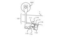
図2は、画像形成装置101にセットされたトナーボトル600からのトナー補給を説明する図であり、図1と同一のものには同一の符号を付してある。
トナーボトル600は、画像形成装置101に着脱可能に構成されている。トナーボトル600は画像形成装置101内に設けられたボトルマウント(不図示)に装着されることで、トナーボトル600の補給口に設けられた図示しない補給口シャッター(不図示)が開放される。
FIG. 2 is a diagram illustrating toner replenishment from a
The
トナーボトル600内部には、螺旋状のトナー搬送部が形成されており、現像器114へのトナー補給指示がされた場合に、トナーボトル600が回転することでトナーボトル600内のトナーは補給口方向に搬送される。さらに、トナーボトル600の回転動作に合わせてトナーボトル600の収縮動作が行われる。これにより、補給口付近に搬送されたトナーボトル600内のトナーは、トナーボトル600の収縮動作に伴うポンピングにより、補給口を通して排出され、ボトルマウントを通してトナー補給経路121を経て現像器114に補給される。
A spiral toner conveying section is formed inside the
ここで、連続してトナーボトル600によるトナー補給動作を行うと、1動作あたりの補給量のバラツキが大きくなる。このため、補給動作を1回行った後に所定時間の補給禁止時間が設けられ、補給禁則時間中には新たに補給動作を実行することはできないように構成されている。
Here, if the toner replenishment operation using the
<現像器へのトナー補給>
図3は、現像器114による現像構成の一例を示す図である。
現像器114は、現像剤としてトナーと磁性キャリアを混合させた二成分現像剤を使用するものとする。図2に示したように、トナーは、画像形成装置101にセットされたトナーボトル600(図2参照)から、現像器114の中に供給される。
<Replenishing toner to the developer>
FIG. 3 is a diagram showing an example of a developing configuration using the developing
The developing
現像器114の中は、隔壁によって仕切られた第一搬送室31と、第二搬送室32があり、それぞれの搬送室は長手方向の両端で繋がっている。第一搬送室31には第一搬送スクリュー33、第二搬送室32には第二搬送スクリュー34がそれぞれ回転可能に支持されており、これら2つの搬送スクリューが駆動されることで、供給されたトナーが2つの搬送室を循環する。
Inside the developing
ここで、現像容器30の中には予め磁性キャリアが入っており、第一搬送室31を循環中に磁性キャリアとトナーが十分攪拌されることで摩擦帯電し、第二搬送室32へと搬送される。第二搬送室32内の第二搬送スクリュー34は現像剤担持体17に対向配置されており、磁性キャリアとの摩擦帯電により磁性キャリアに付着したトナーを、現像剤担持体17に搬送および供給する役割を担う。
Here, the
上述した画像の作像プロセスでは、現像器114内に収容されたトナーを消費することにより、トナー画像を形成している。このため、作像プロセスが行われる度に、現像器114内のトナー量が減少する。このため、現像器114に、トナーの消費量に応じてトナーを補給することが必要である。
In the image forming process described above, a toner image is formed by consuming the toner contained in the developing
トナーの補給量を決定する方法としては、フィードバック制御(以下「FB制御」という)と、フィードフォワード制御(以下「FF制御」という)がある。
FB制御では、現像器114内のトナー量の測定結果からトナー量の目標値からの不足分から補給量を決定する。
FF制御では、形成される画像の画像情報に基づいて作像プロセスにより消費されるトナー量(トナー消費量)を予測して、予測消費量から補給量を決定する。
本実施形態では、FB制御とFF制御の両方を組み合わせて採用している。
Methods for determining the amount of toner replenishment include feedback control (hereinafter referred to as "FB control") and feedforward control (hereinafter referred to as "FF control").
In the FB control, the replenishment amount is determined based on the shortfall from the target value of the toner amount based on the measurement result of the toner amount in the developing
In the FF control, the amount of toner consumed in the image forming process (toner consumption amount) is predicted based on the image information of the image to be formed, and the replenishment amount is determined from the predicted consumption amount.
In this embodiment, a combination of both FB control and FF control is employed.
<トナー補給量制御>
図4は、本実施形態のトナー補給量制御に係るコントローラの一例を示す図である。
画像形成装置101は、コントローラ1100を備える。
コントローラ1100は、現像器114へのトナー補給を制御する。
<Toner supply amount control>
FIG. 4 is a diagram showing an example of a controller related to toner replenishment amount control according to the present embodiment.
A
現像器114へのトナー補給を制御するため、コントローラ1100内には、補給制御演算部1101が設けられている。さらに、補給制御演算部1101内には、後述する記憶領域1105、トナー消費量算出部1102、補給量算出部1103、補給動作制御部1104が設けられている。
In order to control toner replenishment to the developing
上述したFB制御のため、現像器114には、図4に示すインダクタンスセンサ120が配置されている。インダクタンスセンサ120は、現像器114内に蓄積されたトナーの残量を検知する。より具体的に述べると、インダクタンスセンサ120は、現像器114に収容されている現像剤の透磁率を検出し、現像剤中のトナーの割合に応じた信号を出力する。そして、コントローラ1100が、インダクタンスセンサ120の出力信号に基づいて、現像剤を蓄積する蓄積部である現像器114に収容されている現像剤中のトナーの量を検知する。
For the above-described FB control, an
上述したように、現像器114に収容されている現像剤は、磁性を有するキャリアとトナーとを含んでいる。そのため、現像剤中のトナーの割合(以下「現像器トナー濃度」という)が増加すると、現像剤中のキャリアの割合が減少するので、インダクタンスセンサ120の出力値が減少する。一方、現像器トナー濃度が減少すると、現像剤中のキャリアの割合が増加するので、インダクタンスセンサ120の出力値が増加する。つまり、インダクタンスセンサ120は、現像器114内に蓄積された現像剤中のトナーの割合を検知し、この割合に応じた信号をコントローラ1100に出力する。
As described above, the developer contained in the developing
また、画像形成装置101は、画像コントローラ1200を備える。
画像コントローラ1200には、上述したFF制御に用いられる画像情報を取得するため、ビデオカウンタ66が設けられている。
ビデオカウンタ66は、入力された画像データに基づいて、1ページ分の画像に含まれる画素毎の濃度の総和を計数する。
The
The
The
ビデオカウンタ66により計数された画素毎の濃度の総和(以下「ビデオカウント」という)は、画像データに含まれる1ページのトナー像を形成することで現像器114から消費されるトナーの消費量に相当する。なお、ビデオカウントを取得する方法は、公知の技術であるので、ここでの説明を省略する。計数されたビデオカウントは、画像コントローラ1200からコントローラに送信される。
The total density of each pixel counted by the video counter 66 (hereinafter referred to as "video count") is the amount of toner consumed from the developing
コントローラ1100は、1ページ分の画像ごとに画像を識別する識別情報としてのページID(以下「画像番号」)を生成する。コントローラ1100は、画像コントローラ1200から受信したビデオカウントに対して、該ビデオカウントに対応するページ画像の識別情報(画像番号)をビデオカウント番号として付与し、補給制御演算部1101に渡す。補給制御演算部1101は、上述のように取得したビデオカウントからトナー消費量算出部1102によりトナー消費量を算出する。
The
補給制御演算部1101では、インダクタンスセンサ120の検知結果、及び、トナー消費量算出部1102によってビデオカウントから算出されたトナー消費量を、補給量算出部1103にて合わせることでトナー補給量を算出する。そして、算出されたトナー補給量が所定の閾値を超えた場合に、補給動作制御部1104により、現像器114へのトナー補給指令を行う。補給動作制御部1104からの補給指令を受けると、現像器114に連結されたトナー補給経路121を介して、現像器114にトナーボトル600からトナーが補給される。
In the replenishment
<FF制御におけるビデオカウント処理>
ここでFF制御におけるビデオカウント処理に関して、詳細に説明する。
FF制御により現像器114にトナーを補給する場合、現像器114内のトナー量を一定に保つためには現像動作が行われてトナーが消費されるタイミングに合わせて、必要なトナー量を補給する必要がある。
<Video count processing in FF control>
Here, video count processing in FF control will be explained in detail.
When replenishing toner to the developing
コントローラ1100は、転写材の搬送や画像の作像といった各プロセスにおけるタイミング合わせに使用される画像先端信号(Itop信号)を生成する。この画像先端信号(Itop信号)は、ページ画像の形成開始を示すものであり、以下「画像先端位置情報」という。画像先端位置情報は、例えば、上述の中間転写ベルト1上での4色のトナー像の位置合わせや、二次転写部における転写材と中間転写ベルト1上のトナー像の位置合わせ等に使用される。
The
画像先端位置情報が補給量算出部1103に入力された後の一定時間T1経過までの間に、画像データの1ページ分の画像の現像動作によりトナーが消費される。このため、補給量算出部1103は、画像先端位置情報が入力されてから一定時間T1が経過するまでの間の所定タイミングT2にて、トナーの補給量の計算を行なう。これにより、現像動作が行われてトナーが消費されるタイミングに合わせて必要なトナーの補給量を算出でき、必要なトナー量を補給することができる。このため、現像器114内のトナー量を一定に保つことができ、画像の濃度変動を抑制することができる。
After the image leading edge position information is input to the replenishment
コントローラ1100は、ページ画像に対応する画像先端位置情報に、そのページ画像の画像番号を「画像先端位置番号」として付与する。コントローラ1100から補給制御演算部1101に、画像先端位置情報が入力される際に、対応する画像先端位置番号も併せて入力される。また、上述したように、コントローラ1100は、ビデオカウントにも、該ビデオカウントに対応するページ画像の画像番号を「ビデオカウント番号」として付与する。コントローラ1100から補給制御演算部1101に、ビデオカウントが入力される際に、対応するビデオカウント番号も併せて入力される。
The
補給制御演算部1101には、画像先端位置情報、画像先端位置番号、ビデオカウント、ビデオカウント番号のそれぞれを複数記憶可能な記憶領域1105が設けられている。さらに、記憶領域1105には、画像先端位置情報記憶部1106、画像先端位置番号記憶部1107、ビデオカウント記憶部1108、ビデオカウント番号記憶部1109が設けられている。画像先端位置情報記憶部1106は、画像先端位置情報を複数記憶できる。画像先端位置番号記憶部1107は、画像先端位置番号を複数記憶できる。ビデオカウント記憶部1108は、ビデオカウントを複数記憶できる。ビデオカウント番号記憶部1109は、ビデオカウント番号を複数記憶できる。
The replenishment
コントローラ1100から補給制御演算部1101に入力されたそれぞれのデータは、補給制御演算部1101内の記憶領域1105に格納される。上述したように、画像先端位置情報記憶部1106、画像先端位置番号記憶部1107、ビデオカウント記憶部1108、ビデオカウント番号記憶部1109はそれぞれ所定数のデータを格納可能である。これらの記憶部1106~1109は、格納しているデータ数が上限に達した状態で新たにデータが格納されようとすると、最も古いデータを削除して記憶領域を確保するファーストイン・ファーストアウト(以下「FIFO」という)方式で構成されている。
Each piece of data input from the
補給制御演算部1101に画像先端位置情報が入力された場合、併せて入力される画像先端位置番号と、ビデオカウント番号記憶部1109に格納されているビデオカウント番号との照合が行われる。また、補給制御演算部1101にビデオカウントが入力された場合、併せて入力されるビデオカウント番号と、画像先端位置番号記憶部1107に格納されている画像先端位置番号との照合が行われる。
When the image leading edge position information is input to the replenishment
以下、図5は、本実施形態におけるFF制御でのトナー消費量算出処理の一例を示すフローチャートである。このフローチャートの処理は、例えばコントローラ1100が図示しないROM等に格納されたプログラムを読み出して実行することにより実現される。
FIG. 5 is a flowchart illustrating an example of toner consumption calculation processing in FF control in this embodiment. The processing in this flowchart is realized, for example, by the
S20において、コントローラ1100は、補給制御演算部1101にビデオカウントが入力されたか否かを判定する。補給制御演算部1101にビデオカウントが入力されていない場合(S20でNoの場合)、コントローラ1100は、S24に処理を進める。
In S20, the
一方、補給制御演算部1101にビデオカウントが入力された場合(S20でYesの場合)、コントローラ1100は、S21に処理を進める。
S21において、コントローラ1100は、ビデオカウントをビデオカウント記憶部1108に、ビデオカウントと同時入力されたビデオカウント番号をビデオカウント番号記憶部1109に、それぞれ格納する。
On the other hand, if the video count is input to the replenishment control calculation unit 1101 (Yes in S20), the
In S21, the
次にS22において、コントローラ1100は、上記ビデオカウント番号と一致する画像先端位置番号を画像先端位置番号記憶部1107で照合し、S23に処理を進める。
S23において、コントローラ1100は、上記ビデオカウント番号と一致する画像先端位置番号が画像先端位置番号記憶部1107に格納されているか否かを判定する。そして、上記ビデオカウント番号と一致する画像先端位置番号が画像先端位置番号記憶部1107に格納されている場合(S23でYesの場合)、コントローラ1100は、S33に処理を進める。S33以降の処理については後述する。
Next, in S22, the
In S23, the
一方、上記ビデオカウント番号と一致する画像先端位置番号が画像先端位置番号記憶部1107に格納されていない場合(S23でNoの場合)、コントローラ1100は、S24に処理を進める。
On the other hand, if the image leading edge position number that matches the video count number is not stored in the image leading edge position number storage unit 1107 (No in S23), the
S24において、コントローラ1100は、補給制御演算部1101に画像先端位置情報が入力されたか否かを判定する。補給制御演算部1101に画像先端位置情報が入力されていない場合(S24でNoの場合)、コントローラ1100は、S20に処理を戻す。
In S24, the
一方、補給制御演算部1101に画像先端位置情報が入力された場合(S24でYesの場合)、コントローラ1100は、S25に処理を進める。
S25において、コントローラ1100は、画像先端位置情報を画像先端位置情報記憶部1106に、画像先端位置情報と同時入力された画像先端位置番号を画像先端位置番号記憶部1107に、それぞれ格納する。
On the other hand, if the image leading edge position information is input to the replenishment control calculation unit 1101 (Yes in S24), the
In S25, the
次にS26において、コントローラ1100は、上記画像先端位置番号と一致するビデオカウント番号をビデオカウント番号記憶部1109で照合する。
さらにS27において、コントローラ1100は、上記画像先端位置番号と一致するビデオカウント番号がビデオカウント番号記憶部1109に格納されているか否かを判定する。そして、上記画像先端位置番号と一致するビデオカウント番号がビデオカウント番号記憶部1109に格納されている場合(S27でYesの場合)、コントローラ1100は、S33に処理を進める。
Next, in S26, the
Furthermore, in S27, the
S33において、コントローラ1100は、画像先端位置情報の入力タイミングを基に計算された所定タイミングT2になるまで待機する。そして、所定タイミングT2になった場合(S33でYesの場合)、コントローラ1100は、S34に処理を進める。
In S33, the
S34において、コントローラ1100は、トナー消費量算出部1102でビデオカウントを使用したトナー消費量を計算(予測)する。
In S34, the
次にS37において、コントローラ1100は、補給量算出部1103で、上記S34で予測したトナー消費量から、ビデオカウントを用いたFF制御によるトナー補給量を計算(決定)し、本フローチャートの処理を終了する。なお、このフローチャートでは示していないが、所定タイミングT2では、補給量算出部1103はインダクタセンサの出力信号を使用したFB制御によるトナー補給量の計算を行う。そして、上記S37で決定したFF制御によるトナー補給量と、上述したFB制御によるトナー補給量とに基づいて、補給量算出部1103によりトナー補給量の計算が行われる。そして、このトナー補給量を用い、補給動作制御部1104によりトナー補給動作が行われる。
Next, in S37, the
一方、上記S27において、上記画像先端位置番号と一致するビデオカウント番号がビデオカウント番号記憶部1109に格納されていない場合(S27でNoの場合)、コントローラ1100は、S28に処理を進める。
On the other hand, in the above S27, if the video count number that matches the image leading edge position number is not stored in the video count number storage unit 1109 (No in S27), the
S28において、コントローラ1100は、補給制御演算部1101にビデオカウントが入力されたか否かを判定する。補給制御演算部1101にビデオカウントが入力されていない場合(S28でNoの場合)、コントローラ1100は、ビデオカウントが入力されるまで待機する。
In S28, the
一方、補給制御演算部1101にビデオカウントが入力された場合(S28でYesの場合)、コントローラ1100は、S29に処理を進める。
S29において、コントローラ1100は、ビデオカウントをビデオカウント記憶部1108に、ビデオカウントと同時入力されたビデオカウント番号をビデオカウント番号記憶部1109に、それぞれ格納する。
On the other hand, if the video count is input to the replenishment control calculation unit 1101 (Yes in S28), the
In S29, the
次にS30において、コントローラ1100は、上記ビデオカウント番号と一致する画像先端位置番号を画像先端位置番号記憶部1107で照合し、S31に処理を進める。
S31において、コントローラ1100は、上記ビデオカウント番号と一致する画像先端位置番号が画像先端位置番号記憶部1107に格納されているか否かを判定する。そして、上記ビデオカウント番号と一致する画像先端位置番号が画像先端位置番号記憶部1107に格納されていない場合(S31でNoの場合)、コントローラ1100は、S24に処理を戻す。
Next, in S30, the
In S31, the
一方、上記ビデオカウント番号と一致する画像先端位置番号が画像先端位置番号記憶部1107に格納されている場合(S31でYesの場合)、コントローラ1100は、S32に処理を進める。
On the other hand, if the image leading edge position number that matches the video count number is stored in the image leading edge position number storage unit 1107 (Yes in S31), the
S32において、コントローラ1100は、所定タイミングT2となる前に上記ビデオカウントが入力されたか否かを判定する。そして、所定タイミングT2となる前に上記ビデオカウントが入力されたと判定した場合(S32でYesの場合)、コントローラ1100は、S33に処理を進める。S33以降の処理については説明済みのため省略する。
In S32, the
一方、所定タイミングT2以降に上記ビデオカウントが入力されたと判定した場合(S32でNoの場合)、コントローラ1100は、S35に処理を進める。なお、所定タイミングT2では、補給量算出部1103でビデオカウントを基にしたFF制御を除いた、インダクタセンサの出力信号を使用したFB制御のみによる補給量の計算が行なわれる。そして、このトナー補給量を用い、補給動作制御部1104によりトナー補給動作が行われるものとする。すなわち、コントローラ1100は、所定タイミングT2で、ビデオカウントに基づくトナー消費量の予測が可能な場合、FF制御及びFBによりトナー補給量を制御し、トナー消費量の予測ができない場合、FB制御のみによりトナー補給量を制御する。
On the other hand, if it is determined that the video count has been input after the predetermined timing T2 (No in S32), the
S35において、コントローラ1100は、所定タイミングT2から上述した補給禁止時間が経過したか否かを判定する。そして、補給禁止時間が経過していない場合(S35でNoの場合)、コントローラ1100は、補給禁止タイミングと判断し、補給禁止時間の経過するまで待機する。
In S35, the
一方、補給禁止時間が経過した場合(S35でYesの場合)、コントローラ1100は、補給可能タイミングと判断し、S36に処理を進める。
S36において、コントローラ1100は、トナー消費量算出部1102でビデオカウントを使用したトナー消費量を計算(予測)し、S37に処理を進める。S37以降の処理については説明済みのため省略する。
On the other hand, if the replenishment prohibition time has elapsed (Yes in S35), the
In S36, the
以下、具体的に説明する。
<ビデオカウントが画像先端位置情報に先行して補給制御演算部に入力された場合>
この場合、補給制御演算部1101にビデオカウントが入力されるタイミングでは、ビデオカウント番号と一致する画像先端位置番号は画像先端位置番号記憶部1107に格納されていない。このため、補給制御演算部1101へのビデオカウント入力時のビデオカウント番号と画像先端位置番号記憶部1107に格納されている番号との照合では、一致する番号は検出されない(S20、S22、S23)。
This will be explained in detail below.
<When the video count is input to the replenishment control calculation section before the image leading edge position information>
In this case, at the timing when the video count is input to the replenishment
なお、ビデオカウント及びビデオカウント番号は、ビデオカウント記憶部1108及びビデオカウント番号記憶部1109に格納される(S21)。
その後、補給制御演算部1101に画像先端位置情報が入力された時の画像先端位置番号とビデオカウント番号記憶部1109に格納されている番号との照合において、画像先端位置番号と一致する番号が見つけられる(S24~S27)。
これにより、画像先端位置情報の入力タイミングを基に計算された所定タイミングT2において、補給量算出部1103でビデオカウントを用いたFF制御とFB制御を併せて補給量の計算が行われる(S33、S34、S37)。
Note that the video count and video count number are stored in the video
Thereafter, in comparing the image leading edge position number when the image leading edge position information is input to the replenishment
As a result, at a predetermined timing T2 calculated based on the input timing of the image leading edge position information, the replenishment
<画像先端位置情報がビデオカウントに先行して補給制御演算部に入力>
補給制御演算部1101に画像先端位置情報が入力されるタイミングでは、画像先端位置番号と一致するビデオカウント番号はビデオカウント記憶部1108に格納されていない。このため、補給制御演算部1101への画像先端位置情報入力時の画像先端位置番号とビデオカウント番号記憶部1109に格納されている番号との照合では、一致する番号は検出されない(S24、S26、S27)。
<Image leading edge position information is input to the replenishment control calculation unit prior to video count>
At the timing when the image leading edge position information is input to the replenishment
なお、画像先端位置情報及び画像先端位置番号は画像先端位置情報記憶部1106及び画像先端位置番号記憶部1107に格納される(S25)。
その後、補給制御演算部1101にビデオカウントが入力された時のビデオカウント番号と画像先端位置番号記憶部1107に格納されている番号との照合において、ビデオカウント番号と一致する番号が検出される(S28~S31)。
Note that the image leading edge position information and the image leading edge position number are stored in the image leading edge position
Thereafter, by comparing the video count number when the video count is input to the replenishment
所定タイミングT2までにビデオカウントが入力された場合、画像先端位置情報の入力タイミングを基に計算された所定タイミングT2にてビデオカウントを用いたFF制御とFB制御を併せて補給量の計算が行われる(S33、S34、S37)。 If the video count is input by the predetermined timing T2, the replenishment amount is calculated by combining the FF control and the FB control using the video count at the predetermined timing T2 calculated based on the input timing of the image leading edge position information. (S33, S34, S37).
一方、ビデオカウントの入力が所定タイミングT2よりも後になった場合、所定タイミングT2における補給量の計算では、ビデオカウントを基にしたFF制御を除いたFB制御のみによる補給量の計算が行われ、トナーが補給される。なお、所定タイミングT2以降に入力されたビデオカウントは、補給禁止時間が経過した補給可能タイミングにてFF制御によるトナー補給の補給量の計算に使用される(S35、S36、S37)。 On the other hand, if the input of the video count is later than the predetermined timing T2, the replenishment amount at the predetermined timing T2 is calculated only by FB control excluding FF control based on the video count, Toner is replenished. Note that the video count input after the predetermined timing T2 is used to calculate the amount of toner replenishment by FF control at the replenishment enabled timing after the replenishment prohibition time has elapsed (S35, S36, S37).
なお、本実施形態の現像器114へのトナー補給はトナーボトルからの補給動作であったが、トナーボトルからの補給動作で一定量のトナーを格納しておくホッパーにトナーを補給し、ホッパーからの補給動作で現像器にトナーを補給する構成でもよい。
Note that toner replenishment to the developing
また、本実施形態では、現像動作が行われるタイミングの通知に画像先端位置情報(画像先端信号)を使用した。しかし、現像動作タイミングの通知に用いる情報(動作情報)は、画像先端位置情報に限定されるものではない。例えば、画像先端位置情報の代わりに、記録材Sを搬送する紙搬送部150の駆動開始信号や、現像器114の駆動開始信号等の情報を用いてもよい。
Furthermore, in this embodiment, image leading edge position information (image leading edge signal) is used to notify the timing at which a developing operation is performed. However, the information (operation information) used to notify the developing operation timing is not limited to image leading edge position information. For example, instead of the image leading edge position information, information such as a drive start signal for the
また、FF制御に用いられる画像情報としてビデオカウントを使用していたが、画像情報はビデオカウントに限定されるものではない。例えば、ビデオカウントの代わりに、1ページ内に形成される画像の割合等を示す情報を用いてもよい。
さらに、画像先端位置情報やビデオカウントを識別する方法として番号を用いたが、番号に限られるものではなく、文字列や数字を含む文字列等であってもよい。
Furthermore, although a video count has been used as the image information used for FF control, the image information is not limited to the video count. For example, instead of the video count, information indicating the ratio of images formed within one page, etc. may be used.
Furthermore, although numbers are used as a method for identifying image leading edge position information and video counts, the present invention is not limited to numbers, and may be character strings, character strings containing numbers, or the like.
以上説明したように、画像先端位置情報とビデオカウントに識別情報を付与し、画像先端位置情報の識別情報とビデオカウントの識別情報が揃った場合に、ビデオカウントを基にした現像器でのトナー消費量を算出する。これにより、画像の形成で消費されるトナー量を、消費されるタイミングで正確に予測することができる。このため、適切にトナーを補給することができる。この結果、形成する画像の濃度変動を抑制することができる。 As explained above, when identification information is added to the image leading edge position information and the video count, and the identification information of the image leading edge position information and the video count identification information are aligned, the toner in the developing unit based on the video count is Calculate consumption. Thereby, the amount of toner consumed in forming an image can be accurately predicted at the timing of consumption. Therefore, toner can be replenished appropriately. As a result, variations in density of the image to be formed can be suppressed.
〔第2実施形態〕
上記第1実施形態では、ページごとの画像先端位置情報とページごとの画像情報とに基づいてFF制御によるトナー補給量を決定する構成について説明した。第2実施形態では、ページを画像先端から所定長さごとに区切った区間ごとにFF制御によるトナー補給量を決定する構成について説明する。
[Second embodiment]
In the first embodiment, a configuration has been described in which the amount of toner replenishment is determined by FF control based on the image leading edge position information for each page and the image information for each page. In the second embodiment, a configuration will be described in which the amount of toner replenishment is determined by FF control for each section in which a page is divided into sections of a predetermined length from the leading edge of the image.
この構成の場合、ビデオカウンタ66は、画像のビデオカウントを、1ページ分全てではなく、画像先端から所定長さごとに区切った区間にて計数する。コントローラ1100は、区切られた区間ごとの区間ビデオカウントに対して、識別情報となる区間ビデオカウント番号を付与する。
In the case of this configuration, the
また、コントローラ1100は、現像動作に対し、画像先端から所定長さごとに区切った区間の現像プロセスが行われるタイミングにて、区間先端位置情報および区間先端位置番号を生成する。そして、上記の区間先端位置情報、区間先端位置番号、区間ビデオカウント、区間ビデオカウント番号を使用し、第1実施形態と同様のFF制御を行う。
すなわち、所定単位(ページ単位、区間単位、その他でもよい)の画像を形成する際の先端位置情報、所定単位の画像のビデオカウントを用いる構成であればよい。
これにより、第1実施形態と同様の効果を奏する。
In addition, the
That is, any configuration may be used as long as it uses the tip position information when forming an image in a predetermined unit (page unit, section unit, etc.) and the video count of the predetermined unit image.
This produces the same effects as the first embodiment.
なお、上記説明では、現像器へトナー補給する構成について説明したが、プロセスカートリッジへのトナーを補給する場合にも、本発明は適用可能である。 In the above description, the configuration for replenishing toner to a developing device has been described, but the present invention is also applicable to the case of replenishing toner to a process cartridge.
上述したように、例えば安価なコントローラを備えた画像形成装置では、画像先端位置情報の通知よりも画像情報が先行して通知されたり、画像情報が通知されるタイミングが大幅に遅れてしまう場合がある。このような場合でも、上記各実施形態によれば、画像の形成で消費されるトナー量を、消費されるタイミングで正確に予測できる。これにより、適切にトナーを補給することができる。この結果、形成する画像の濃度変動を抑制することができる。 As described above, for example, in an image forming apparatus equipped with an inexpensive controller, the image information may be notified before the image leading edge position information, or the timing at which the image information is notified may be significantly delayed. be. Even in such a case, according to each of the embodiments described above, the amount of toner consumed in forming an image can be accurately predicted at the timing of consumption. Thereby, toner can be replenished appropriately. As a result, variations in density of the image to be formed can be suppressed.
なお、上述した各種データの構成及びその内容はこれに限定されるものではなく、用途や目的に応じて、様々な構成や内容で構成されることは言うまでもない。
以上、一実施形態について示したが、本発明は、例えば、システム、装置、方法、プログラムもしくは記憶媒体等としての実施態様をとることが可能である。具体的には、複数の機器から構成されるシステムに適用しても良いし、また、一つの機器からなる装置に適用しても良い。
また、上記各実施形態を組み合わせた構成も全て本発明に含まれるものである。
It goes without saying that the configurations and contents of the various data described above are not limited to these, and may be configured in various configurations and contents depending on the use and purpose.
Although one embodiment has been described above, the present invention can be implemented as, for example, a system, an apparatus, a method, a program, a storage medium, or the like. Specifically, the present invention may be applied to a system consisting of a plurality of devices, or may be applied to a device consisting of a single device.
Moreover, all configurations that combine the above embodiments are also included in the present invention.
(その他の実施形態)
本発明は、上述の実施形態の1以上の機能を実現するプログラムを、ネットワーク又は記憶媒体を介してシステム又は装置に供給し、そのシステム又は装置のコンピュータにおける1つ以上のプロセッサーがプログラムを読出し実行する処理でも実現可能である。また、1以上の機能を実現する回路(例えば、ASIC)によっても実現可能である。
また、本発明は、複数の機器から構成されるシステムに適用しても、1つの機器からなる装置に適用してもよい。
本発明は上記実施形態に限定されるものではなく、本発明の趣旨に基づき種々の変形(各実施形態の有機的な組合せを含む)が可能であり、それらを本発明の範囲から除外するものではない。即ち、上述した各実施形態及びその変形例を組み合わせた構成も全て本発明に含まれるものである。
(Other embodiments)
The present invention provides a system or device with a program that implements one or more of the functions of the embodiments described above via a network or a storage medium, and one or more processors in the computer of the system or device reads and executes the program. This can also be achieved by processing. It can also be realized by a circuit (for example, ASIC) that realizes one or more functions.
Furthermore, the present invention may be applied to a system made up of a plurality of devices, or to a device made up of one device.
The present invention is not limited to the above embodiments, and various modifications (including organic combinations of each embodiment) are possible based on the spirit of the present invention, and these are excluded from the scope of the present invention. isn't it. That is, all configurations in which the above-described embodiments and their modifications are combined are also included in the present invention.
101 画像形成装置
114 現像器
66 ビデオカウンタ
1100 コントローラ
1105 記憶領域
1102 トナー消費量算出部
1103 補給量算出部
1104 補給動作制御部
101
Claims (7)
前記画像形成手段で所定単位の画像を形成する際の動作情報に対して、該所定単位の画像の識別情報を付与する第1付与手段と、
前記画像形成手段で前記所定単位の画像を形成するための画像データに基づき生成される画像情報に対して、該所定単位の画像の識別情報を付与する第2付与手段と、
前記動作情報に基づく所定タイミングで、該動作情報に付与された識別情報に対応する識別情報が付与された前記画像情報に基づきトナーの消費量を予測する予測手段と、
前記予測されたトナーの消費量に基づき前記補給手段によるトナーの補給量を制御する制御手段と、
前記現像器に収容されるトナーの残量を検出する検出手段と、を有し、
前記制御手段は、
前記所定タイミングで、前記トナーの消費量が予測が可能な場合、前記トナーの消費量及び前記検出されたトナーの残量に基づき前記トナーの補給量を制御し、
前記所定タイミングで、前記トナーの消費量の予測ができない場合、前記検出されたトナーの残量に基づき前記補給手段によるトナーの補給量を制御する、
ことを特徴とする画像形成装置。 An image forming apparatus comprising: an image forming means for forming a toner image by developing a latent image formed based on image data using toner contained in a developing device; and a replenishing means for replenishing the developing device with toner. And,
a first assigning unit that assigns identification information of the predetermined unit of image to operation information when the image forming unit forms the predetermined unit of image;
a second assigning unit for assigning identification information of the predetermined unit of image to image information generated based on image data for forming the predetermined unit of image by the image forming unit;
a prediction unit that predicts toner consumption based on the image information to which identification information corresponding to identification information added to the operational information is added at a predetermined timing based on the operational information;
control means for controlling the amount of toner replenishment by the replenishing means based on the predicted toner consumption amount;
a detection means for detecting the remaining amount of toner contained in the developing device;
The control means includes:
If the toner consumption amount can be predicted at the predetermined timing, controlling the toner replenishment amount based on the toner consumption amount and the detected toner remaining amount;
If the toner consumption amount cannot be predicted at the predetermined timing, controlling the toner replenishment amount by the replenishing means based on the detected toner remaining amount;
An image forming apparatus characterized by :
前記予測手段は、
前記動作情報を取得した際に、該動作情報に付与された識別情報に対応する識別情報が付与された前記画像情報が前記記憶手段に記憶されていない場合には、その後に取得される該画像情報に基づきトナーの消費量を予測し、
前記動作情報を取得した際に、該動作情報に付与された識別情報に対応する識別情報が付与された前記画像情報が前記記憶手段に記憶されている場合には、該記憶されている画像情報に基づきトナーの消費量を予測する、
ことを特徴とする請求項1に記載の画像形成装置。 comprising a storage means capable of storing a plurality of pieces of image information to which the identification information has been added;
The prediction means is
When the motion information is acquired, if the image information to which identification information corresponding to the identification information assigned to the motion information is attached is not stored in the storage means, the image to be acquired thereafter. Predict toner consumption based on information,
When the motion information is acquired, if the image information to which identification information corresponding to the identification information assigned to the motion information is attached is stored in the storage means, the stored image information Predict toner consumption based on
The image forming apparatus according to claim 1, characterized in that:
前記予測手段は、前記動作情報に基づく所定タイミングより後に、該動作情報に付与された識別情報に対応する識別情報が付与された前記画像情報が取得された場合、該所定タイミングから前記所定時間が経過した後に、該画像情報に基づきトナーの消費量を予測する、
ことを特徴とする請求項1に記載の画像形成装置。 The replenishing means prohibits replenishment of toner for a predetermined time after replenishing the toner,
When the image information to which identification information corresponding to the identification information added to the movement information is acquired after a predetermined timing based on the movement information, the prediction means calculates the predetermined time from the predetermined timing. predicting toner consumption based on the image information after the elapsed time;
The image forming apparatus according to claim 1 , characterized in that:
Priority Applications (1)
| Application Number | Priority Date | Filing Date | Title |
|---|---|---|---|
| JP2019121040A JP7346100B2 (en) | 2019-06-28 | 2019-06-28 | Image forming device |
Applications Claiming Priority (1)
| Application Number | Priority Date | Filing Date | Title |
|---|---|---|---|
| JP2019121040A JP7346100B2 (en) | 2019-06-28 | 2019-06-28 | Image forming device |
Publications (2)
| Publication Number | Publication Date |
|---|---|
| JP2021006861A JP2021006861A (en) | 2021-01-21 |
| JP7346100B2 true JP7346100B2 (en) | 2023-09-19 |
Family
ID=74165142
Family Applications (1)
| Application Number | Title | Priority Date | Filing Date |
|---|---|---|---|
| JP2019121040A Active JP7346100B2 (en) | 2019-06-28 | 2019-06-28 | Image forming device |
Country Status (1)
| Country | Link |
|---|---|
| JP (1) | JP7346100B2 (en) |
Citations (4)
| Publication number | Priority date | Publication date | Assignee | Title |
|---|---|---|---|---|
| JP2000214672A (en) | 1999-01-26 | 2000-08-04 | Sharp Corp | Image forming device |
| JP2004151375A (en) | 2002-10-30 | 2004-05-27 | Sharp Corp | Printing system |
| JP2009265582A (en) | 2008-04-30 | 2009-11-12 | Ricoh Co Ltd | Image forming apparatus and image forming method |
| JP2012242425A (en) | 2011-05-16 | 2012-12-10 | Ricoh Co Ltd | Image forming device |
-
2019
- 2019-06-28 JP JP2019121040A patent/JP7346100B2/en active Active
Patent Citations (4)
| Publication number | Priority date | Publication date | Assignee | Title |
|---|---|---|---|---|
| JP2000214672A (en) | 1999-01-26 | 2000-08-04 | Sharp Corp | Image forming device |
| JP2004151375A (en) | 2002-10-30 | 2004-05-27 | Sharp Corp | Printing system |
| JP2009265582A (en) | 2008-04-30 | 2009-11-12 | Ricoh Co Ltd | Image forming apparatus and image forming method |
| JP2012242425A (en) | 2011-05-16 | 2012-12-10 | Ricoh Co Ltd | Image forming device |
Also Published As
| Publication number | Publication date |
|---|---|
| JP2021006861A (en) | 2021-01-21 |
Similar Documents
| Publication | Publication Date | Title |
|---|---|---|
| US7398027B2 (en) | Image forming apparatus with conveyance speed control based in part on loop detection | |
| JP7065624B2 (en) | Image forming device, control method of image forming device | |
| JP5863011B2 (en) | Image forming apparatus | |
| JP2006293240A (en) | Image forming apparatus | |
| US9389536B2 (en) | Image forming apparatus | |
| US9116464B2 (en) | Developing device and image forming apparatus | |
| JP5545541B2 (en) | Image forming apparatus | |
| JP7065625B2 (en) | Image forming device, control method of image forming device | |
| JP7346100B2 (en) | Image forming device | |
| JP2006208919A (en) | Image forming apparatus | |
| JP5945923B2 (en) | Image forming apparatus | |
| JP2019159056A (en) | Image forming apparatus | |
| JP2004117734A (en) | Image forming apparatus and its control method | |
| JP2004102051A (en) | Image forming apparatus | |
| JP5316934B2 (en) | Image forming apparatus | |
| JP7277646B2 (en) | IMAGE FORMING APPARATUS AND IMAGE FORMING APPARATUS CONTROL METHOD | |
| JP2004070152A (en) | Color image forming device | |
| JP2004038048A (en) | Image forming apparatus | |
| JP5822801B2 (en) | Image forming apparatus | |
| JP2010091802A (en) | Image forming apparatus | |
| JP7215279B2 (en) | image forming device | |
| JP2011175154A (en) | Image forming device, maintenance management system of the same, method of calculating lifetime of developer, developer lifetime calculation program and storage medium | |
| JP2009288352A (en) | Image forming apparatus and control method therefor | |
| JP6032023B2 (en) | Image forming apparatus | |
| JP2023090870A (en) | Information processing device and control method therefor |
Legal Events
| Date | Code | Title | Description |
|---|---|---|---|
| A621 | Written request for application examination |
Free format text: JAPANESE INTERMEDIATE CODE: A621 Effective date: 20220628 |
|
| A977 | Report on retrieval |
Free format text: JAPANESE INTERMEDIATE CODE: A971007 Effective date: 20230315 |
|
| A131 | Notification of reasons for refusal |
Free format text: JAPANESE INTERMEDIATE CODE: A131 Effective date: 20230404 |
|
| A521 | Request for written amendment filed |
Free format text: JAPANESE INTERMEDIATE CODE: A523 Effective date: 20230602 |
|
| TRDD | Decision of grant or rejection written | ||
| A01 | Written decision to grant a patent or to grant a registration (utility model) |
Free format text: JAPANESE INTERMEDIATE CODE: A01 Effective date: 20230808 |
|
| A61 | First payment of annual fees (during grant procedure) |
Free format text: JAPANESE INTERMEDIATE CODE: A61 Effective date: 20230906 |
|
| R151 | Written notification of patent or utility model registration |
Ref document number: 7346100 Country of ref document: JP Free format text: JAPANESE INTERMEDIATE CODE: R151 |