JP6032023B2 - Image forming apparatus - Google Patents
Image forming apparatus Download PDFInfo
- Publication number
- JP6032023B2 JP6032023B2 JP2013008253A JP2013008253A JP6032023B2 JP 6032023 B2 JP6032023 B2 JP 6032023B2 JP 2013008253 A JP2013008253 A JP 2013008253A JP 2013008253 A JP2013008253 A JP 2013008253A JP 6032023 B2 JP6032023 B2 JP 6032023B2
- Authority
- JP
- Japan
- Prior art keywords
- toner
- density
- toner density
- supply control
- target value
- Prior art date
- Legal status (The legal status is an assumption and is not a legal conclusion. Google has not performed a legal analysis and makes no representation as to the accuracy of the status listed.)
- Active
Links
Images


Description
本発明は、複写機、プリンタ、ファクシミリ又はそれらの複合機等の電子写真方式を用いた画像形成装置に関するものである。 The present invention relates to an image forming apparatus using an electrophotographic system such as a copying machine, a printer, a facsimile, or a complex machine thereof.
潜像担持体たる感光体と、感光体の表面に担持された静電潜像を現像する現像手段たる現像器と、現像器内にトナーを補給するトナー補給装置とを有する画像形成装置において、以下のものが既に知られている。 In an image forming apparatus comprising: a photosensitive member as a latent image carrier; a developing unit as a developing unit that develops an electrostatic latent image carried on the surface of the photosensitive member; and a toner replenishing device that replenishes toner in the developing unit. The following are already known:
現像器は、回転する現像スリーブの表面に担持した現像剤を現像スリーブの回転に伴って現像領域に搬送する。そして、現像スリーブと感光体とが対向している現像領域にて、トナーと磁性キャリアとを含有する二成分現像剤中のトナーを感光体上の静電潜像に転移させることで静電潜像を現像する。 The developing device conveys the developer carried on the surface of the rotating developing sleeve to the developing area as the developing sleeve rotates. The toner in the two-component developer containing the toner and the magnetic carrier is transferred to the electrostatic latent image on the photosensitive member in the developing region where the developing sleeve and the photosensitive member are opposed to each other. Develop the image.
現像に使用されたことでトナー濃度を低下させた現像剤は、現像ローラの回転に伴って現像器内の現像剤収容部に戻される。現像剤収容部内の現像剤のトナー濃度は、透磁率センサ等からなるトナー濃度検知手段によって検知される。現像に伴ってトナー濃度を低下させた現像剤が現像剤収容部に戻されるのに伴って、現像剤収容部内の現像剤のトナー濃度が目標値を下回ると、それが制御部で検知される。 The developer whose toner density has been reduced by being used for development is returned to the developer accommodating portion in the developing device as the developing roller rotates. The toner concentration of the developer in the developer accommodating portion is detected by a toner concentration detecting means including a magnetic permeability sensor. When the developer whose toner concentration has been lowered with the development is returned to the developer accommodating portion and the toner concentration of the developer in the developer accommodating portion falls below the target value, this is detected by the control portion. .
制御部は、所定のタイミングでトナー濃度検知手段によるトナー濃度の検知結果を取得し、その検知結果と所定の目標値の差分とに基づいた駆動量でトナー補給装置を駆動することで、現像剤収容部にトナーを補給して現像剤のトナー濃度を回復させる。 The control unit acquires a toner density detection result by the toner density detection unit at a predetermined timing, and drives the toner replenishing device with a driving amount based on the detection result and a difference between the predetermined target values. Toner is replenished to the storage portion to restore the toner density of the developer.
このトナー補給装置の駆動量を算出する方法(以下、「トナー補給制御」という)としては、以下の2つの方法が知られている。
第1のトナー補給制御は、画像形成装置の潜像担持体上に露光装置(潜像形成手段)が潜像形成する際に用いるピクセル数等の画像書き込み情報(画像情報)から、その潜像を現像することで消費すると予想されるトナー消費量を算出し、算出したトナー消費量に見合った量のトナーを補給する方法である。
The following two methods are known as methods for calculating the driving amount of the toner replenishing device (hereinafter referred to as “toner replenishment control”).
In the first toner replenishment control, the latent image is obtained from image writing information (image information) such as the number of pixels used when the exposure device (latent image forming means) forms a latent image on the latent image carrier of the image forming apparatus. In this method, the toner consumption amount expected to be consumed by developing the toner is calculated, and an amount of toner corresponding to the calculated toner consumption amount is replenished.
第2のトナー補給制御は、周知のPID制御を利用して、トナー補給装置の駆動量を決定する方法である。トナー補給制御におけるPID制御では、トナー濃度を制御対象として、制御対象の現在値と目標値との差分に基づいて、比例処理(P)、積分処理(I)及び微分処理(D)によってそれぞれ必要制御量を算出する。そして、それらの総和を制御量として制御対象を制御する。 The second toner replenishment control is a method for determining the driving amount of the toner replenishing device using the well-known PID control. In the PID control in the toner replenishment control, the toner density is set as a control target, and is necessary for each of proportional processing (P), integration processing (I), and differentiation processing (D) based on the difference between the current value of the control target and the target value. A control amount is calculated. Then, the controlled object is controlled using the sum of them as a control amount.
第1のトナー補給制御では消費によるトナー濃度変動をなくし、第2のトナー補給制御ではトナー濃度をトナー濃度目標値にするためトナー補給を行うことができるため、第1、第2のトナー補給制御を組み合わせて画像品質を安定させることができる。 In the first toner replenishment control, toner density fluctuations due to consumption can be eliminated, and in the second toner replenishment control, toner replenishment can be performed to set the toner density to the toner density target value. Can be combined to stabilize the image quality.
一方、同じトナー濃度の現像剤であっても、トナーの単位重量当たりの帯電量(Q/M)が変化すると、現像領域で現像剤の磁性キャリアから潜像に転移するトナー量が変化することから、現像濃度が変化してしまう。このため、トナー濃度を単純に一定の目標値に調整しているだけでは、長期に渡って現像濃度を安定化させることはできない。そこで、像担持体上にテストトナー像を形成してそのトナー付着量(画像濃度)を検知した結果に基づいて、トナー濃度の目標値を補正する目標値補正処理を定期的に実施する方法が既に知られている。 On the other hand, even if the developer has the same toner concentration, if the charge amount (Q / M) per unit weight of the toner changes, the amount of toner transferred from the magnetic carrier of the developer to the latent image changes in the development area. Therefore, the developing density changes. For this reason, the development density cannot be stabilized over a long period of time simply by adjusting the toner density to a constant target value. Therefore, there is a method of periodically performing a target value correction process for correcting the target value of the toner density based on the result of forming the test toner image on the image carrier and detecting the toner adhesion amount (image density). Already known.
しかし、今までのPID制御を用いたトナー補給制御では、トナー補給量が各装置の固体差や環境により設計値から離れてしまうと、トナー濃度とトナー濃度目標値との差が大きくなりやすい。また、トナー濃度とトナー濃度目標値との差が大きくなると、短時間にトナーを大量に補給するためトナー濃度の時間変化が大きくなってしまい、印刷頁間に濃度ムラが発生するという問題があった。 However, in the toner replenishment control using the conventional PID control, if the toner replenishment amount deviates from the design value due to the individual difference or environment of each device, the difference between the toner density and the toner density target value tends to increase. In addition, when the difference between the toner density and the toner density target value becomes large, a large amount of toner is replenished in a short time, so that the change in the toner density with time increases, and density unevenness occurs between printed pages. It was.
特許文献1には、トナーを短時間に大量に補給させない目的で、トナー濃度目標値を段階的に変化させることが開示されている。しかし、印刷途中でトナー補給量が各装置の固体差や環境により設計値から離れてしまうと、トナー濃度とトナー濃度目標値との差が大きくなり、結局トナーを短時間に大量に補給してしまう。
本発明は、画像形成装置においてトナー濃度とトナー濃度目標値との差が大きくなった場合でも、トナーを短時間に大量に補給せず、印刷頁間の濃度ムラを小さくすることを目的とする。 An object of the present invention is to reduce density unevenness between printed pages without supplying a large amount of toner in a short time even when the difference between the toner density and the toner density target value becomes large in the image forming apparatus. .
前記課題を解決するため、本発明は、潜像担持体と、画像情報に基づいて前記潜像担持体上に潜像を形成する潜像形成手段と、トナーを用いて前記潜像担持体上の潜像を現像する現像装置と、前記現像装置内のトナー濃度を検知するトナー濃度検知手段と、前記潜像形成手段からの画像情報及び前記トナー濃度検知手段からのトナー濃度情報が入力されるトナー補給制御装置と、前記トナー補給制御装置で算出されるトナー補給量を補給するトナー補給装置と、を有する画像形成装置において、前記トナー補給制御装置は、トナー濃度目標値から所定の濃度だけ濃い値を第1の補給制御閾値、前記トナー濃度目標値から所定の濃度だけ薄い値を第2の補給制御閾値として設定し、前記トナー濃度と前記トナー濃度目標値との差が、前記第2の又は第1の補給制御閾値と前記トナー濃度目標値との差よりも大きい場合、前記トナー補給制御装置は、出力画像のピクセル数を基にトナー消費量を算出し、算出した前記トナー消費量に所定量を加算又は減算して前記トナー補給量を算出し(定量制御法)、前記トナー濃度と前記トナー濃度目標値との差が、前記第2の又は第1の補給制御閾値と前記トナー濃度目標値との差以下の場合、前記トナー補給制御装置は、PID制御により前記トナー濃度を前記トナー濃度目標値に近づけるために所要の前記トナー補給量を算出する(PID制御法)画像形成装置を提案する。 In order to solve the above problems, the present invention provides a latent image carrier, latent image forming means for forming a latent image on the latent image carrier based on image information, and toner on the latent image carrier. A developing device for developing the latent image, a toner density detecting means for detecting the toner density in the developing device, image information from the latent image forming means, and toner density information from the toner density detecting means. In an image forming apparatus having a toner supply control device and a toner supply device for supplying a toner supply amount calculated by the toner supply control device, the toner supply control device is darker by a predetermined density than a toner density target value. A value is set as a first supply control threshold, and a value that is a predetermined density lower than the toner density target value is set as a second supply control threshold, and the difference between the toner density and the toner density target value is the second supply control threshold. Is greater than the difference between the first replenishment control threshold and the toner density target value, the toner replenishment control device calculates a toner consumption amount based on the number of pixels of the output image, and the calculated toner consumption amount The toner replenishment amount is calculated by adding or subtracting a predetermined amount (quantitative control method), and the difference between the toner concentration and the toner concentration target value is the second or first replenishment control threshold value and the toner concentration. When the difference from the target value is less than or equal to the target value, the toner replenishment control device calculates the toner replenishment amount required to bring the toner density close to the toner density target value by PID control (PID control method). suggest.
トナー補給量が各装置の固体差や環境により設計値から離れてしまっても、トナーは短時間に大量に補給されず、印刷頁間や印刷頁内の濃度ムラを小さくすることができる。 Even if the toner replenishment amount deviates from the design value due to the individual difference or environment of each apparatus, a large amount of toner is not replenished in a short time, and density unevenness between printed pages or within printed pages can be reduced.
以下、本発明の実施形態を図面に基づいて説明する。
図1は、実施形態に係る画像形成装置の一例であるフルカラープリンタの概略を示す断面構成図である。この図に示すフルカラープリンタ1の装置本体2内の略中央部には、4つのドラム状の潜像担持体としての感光体3Y,3M,3C,3Bkが、水平状態で図中左右方向に等間隔で離間して並列に配設されている。なお、添え字Y,M,C,Bkは各々イエロー、マゼンタ、シアン、ブラックの色を示し、この添え字は必要に応じて割愛する。イエロー画像用の感光体3Yに着目すると、この感光体3Yは例えば直径30〜100mm程度のアルミニウム円筒表面に光導電性物質である有機半導体層を設けた構造よりなり、図中時計回り方向(図に示す矢印方向)に回転駆動される。感光体3Yの下方側周囲には静電写真プロセスに従い帯電ローラ4Y、現像ローラ5Yを有する現像装置6Y、クリーニング器7Y等の作像手段が順に配設されている。マゼンタ、シアン、ブラック画像用の感光体3M,3C,3Bk側についても同様である。即ち、用いるトナーの色が異なるだけである。なお、感光体としてはベルト状のものを用いることも可能である。
Hereinafter, embodiments of the present invention will be described with reference to the drawings.
FIG. 1 is a cross-sectional configuration diagram illustrating an outline of a full-color printer which is an example of an image forming apparatus according to an embodiment. In the substantially central portion of the apparatus
感光体3Y,3M,3C,3Bk及び帯電ローラ4、現像装置6、クリーニング器7の下方には、各色の画像データ対応のレーザ光を一様帯電済みの感光体3Y,3M,3C,3Bkに対してスキャニング照射し、潜像形成手段としての露光装置8が設けられている。各帯電ローラ4と各現像ローラ5との間には、この露光装置8から照射されるレーザ光が感光体3Y,3M,3C,3Bkに向けて入り込むように細長いスペース(スリット)が確保されている。図示例の露光装置8は、レーザ光源、ポリゴンミラー等を用いたレーザスキャン方式のものを示したが、LEDアレイと結像手段とを組合せた方式の露光装置を用いることもできる。
Below the
感光体3Y,3M,3C,3Bkの上部には、複数のローラ9,10,11により支持されて反時計回り方向に回転駆動される中間転写ベルト12が設けられている。この中間転写ベルト12は各感光体3Y,3M,3C,3Bkに対して共通なものであり、各感光体3Y,3M,3C,3Bkの現像工程後の一部が接触するように略水平状態で扁平に配置されており、ベルト内周部には各感光体3Y,3M,3C,3Bkに対向させて転写ローラ13Y,13M,13C,13Bkが設けられている。中間転写ベルト12の外周部に対しては、例えば、ローラ11に対向する位置にクリーニング装置14が設けられている。このクリーニング装置14はベルト表面に残留する不要なトナーを拭い去る。なお、この中間転写ベルト12としては、例えば、基体の厚さが50〜600μmの樹脂フィルム或いはゴムを基体とするベルトであって、感光体3Y,3M,3C,3Bkからのトナー像を転写可能とする抵抗値を有する。
Above the
また、装置本体2内において露光装置8の下方には複数段、本例では2段の給紙カセット23,24が引き出し自在に配設されている。これらの給紙カセット23,24内に収納された記録媒体としての用紙Sは対応する給紙ローラ25,26により選択的に給紙されるもので、転写位置に向けて給紙搬送経路27が略垂直に形成されている。中間転写ベルト12の側方には搬送ベルト35が配設されている。この搬送ベルト35のループ内において、2次転写手段としての2次転写ローラ18が中間転写ベルト12の支持ローラの一つであるローラ9と対向するように設けられている。ローラ9と2次転写ローラ18は中間転写ベルト12及び搬送ベルト35を挟んで圧接され、所定の転写ニップを形成する。その転写位置直前の給紙搬送経路27には、転写位置への給紙タイミングをとる一対のレジストローラ28が設けられている。さらに、転写位置上方には給紙搬送経路27に連続し、装置本体2の上部の排紙スタック部29につながる搬送排紙経路30が形成されている。この搬送排紙経路30中には一対の定着ローラを有する定着装置31や、一対の排紙ローラ32等が配設されている。
In the apparatus
なお、装置本体2内において排紙スタック部29下部の空間は各感光体3Y,3M,3C,3Bkで用いる各色のトナーを収納し、そのトナーを対応する現像装置6にポンプ等により搬送供給可能なトナー容器収納部33が設けられている。
The space below the
このような構成において、用紙Sに画像を形成する動作について説明する。
先ず、パーソナルコンピュータ、スキャナー、ファクシミリ等から、出力画像に対応する画像信号がコントローラ50に伝送される。コントローラ50は、この画像信号を制御動作により決定された適正な出力画像信号に変換し、露光装置8に伝送する。露光装置8では半導体レーザから出射されたイエロー用の画像データ対応のレーザ光が帯電ローラ4Yにより一様帯電済みの感光体3Yの表面に照射されることにより静電潜像が形成される。この静電潜像は現像装置6Yによる現像処理を受けてイエロートナーで現像され、可視像となり、感光体3Yと同期して移動する中間転写ベルト12上に転写ローラ13Yによる転写作用を受けて転写される。このような潜像形成、現像、転写動作は感光体3M,3C,3Bk側でもタイミングをとって順次同様に行われる。この結果、中間転写ベルト12上には、イエローY、マゼンタM、シアンC及びブラックBkの各色トナー画像が順次重なり合ったフルカラートナー画像として担持され、搬送される。
An operation of forming an image on the paper S in such a configuration will be described.
First, an image signal corresponding to an output image is transmitted to the
一方、給紙カセット23,24のいずれかから用紙Sが給紙され、給紙搬送経路27を通ってレジストローラ28へと搬送される。中間転写ベルト12上のフルカラートナー画像とタイミングをとって用紙Sがレジストローラ28より送り出され、2次転写ローラ18の作用により中間転写ベルト12上のフルカラートナー画像が用紙S上に転写される。フルカラートナー像が転写された用紙Sは搬送ベルト35により定着装置31へと搬送され、定着装置31による定着処理を経て排紙ローラ32により排紙スタック部29上に排紙される。
On the other hand, the sheet S is fed from one of the
両面印刷の場合は、定着後の用紙Sを切換爪38を切り換えることにより反転路36へ導き、切換爪39を切り換えることにより反転後の用紙Sを再給紙路37からレジストローラ28へと再給紙して用紙の表裏を反転させる。このとき、中間転写ベルト12上には裏面画像となるトナー像を形成して担持させておき、用紙Sの裏面(第二面)にトナー像を転写して定着装置31による定着処理を経て排紙ローラ32により排紙スタック部29上に排紙する。
In the case of duplex printing, the fixed sheet S is guided to the reversing
なお、ここではフルカラー印刷の場合で説明したが、特定色あるいはブラックによるモノクロ印刷時であっても、使用されない感光体が存在するだけで、動作的には同様である。 Although the case of full-color printing has been described here, even in monochrome printing with a specific color or black, there is a photoconductor that is not used, and the operation is the same.
図2は、実施形態に係るトナー補給制御を実行する制御系の一例を示すブロック図である。
図2に示す制御系において、トナー補給制御装置100には、現像装置6に取り付けられたトナー濃度検知手段(不図示)からトナー濃度情報が入力される。また、制御装置100には、露光装置8から潜像形成に用いる画像情報が入力される。本実施形態の制御装置100は、例えばプリント基板を実体とし、トナー濃度情報を用いたPID制御と画像情報を用いた定量制御とを併用したトナー補給制御を実行する。具体的には、PID制御では制御装置100は、トナー濃度検知手段からのトナー濃度情報と目標トナー濃度との差分値に基づいて、現在のトナー濃度を目標トナー濃度へ回復させるために必要なトナー補給量を算出する。また、定量制御では制御装置100は、露光装置8からの画像情報に基づいて、その画像情報に基づく画像形成動作により消費されるトナー量を予測し、そのトナー消費によるトナー濃度低下を抑制するのに必要なトナー補給量を算出する。制御装置100は、トナー補給量のトナーが現像装置6へ補給されるようにトナー補給装置70を制御する。
FIG. 2 is a block diagram illustrating an example of a control system that executes toner supply control according to the embodiment.
In the control system shown in FIG. 2, toner concentration information is input to the toner
図3は、PID制御においてトナー濃度とトナー濃度目標値の差が大きくなった際のトナー濃度変化について説明する図である。
従来から、トナー濃度をトナー濃度目標値に近づけるためにPID制御を用いていた。PID制御を用いると、図示のように、トナー濃度とトナー濃度目標値の差が大きい区間(a)においてはトナー濃度の傾きが大きくなり、差が小さい区間(b)においては傾きが小さくなる。区間(a)では単位時間当たりのトナー濃度変化量が大きくなるため、印刷頁間又は頁内に大きな画像濃度変化が生じてしまう。
FIG. 3 is a diagram for explaining a change in toner density when the difference between the toner density and the toner density target value is increased in PID control.
Conventionally, PID control has been used to bring the toner density close to the toner density target value. If PID control is used, as shown in the figure, the gradient of the toner density increases in the section (a) where the difference between the toner density and the toner density target value is large, and the slope decreases in the section (b) where the difference is small. In the section (a), the toner density change amount per unit time becomes large, so that a large image density change occurs between printed pages or within pages.
図4は、PID制御においてゲインを低くした際のトナー濃度変化について説明する図である。
図示のように、従来技術においてPID制御においてゲインを低く設定すると、トナー濃度の傾きを小さくし、トナー濃度がトナー濃度目標値に近づく速度を遅らせることが出来る。しかし、トナー濃度とトナー濃度目標値との差が小さくなった区間(c)では、トナー補給量に誤差が生じた場合、トナー濃度をトナー濃度目標値に再度近づけられず、トナー濃度が薄くなったり濃くなったり振動してしまうことがある。
FIG. 4 is a diagram for explaining a change in toner density when the gain is lowered in PID control.
As shown in the figure, when the gain is set low in the PID control in the prior art, the gradient of the toner density can be reduced and the speed at which the toner density approaches the toner density target value can be delayed. However, in the interval (c) where the difference between the toner density and the toner density target value is small, if an error occurs in the toner replenishment amount, the toner density cannot be brought close to the toner density target value again, and the toner density becomes low. May become dark or vibrate.
図5は、特許文献1におけるトナー濃度変化の課題について説明する図である。
特許文献1では、図3で示した課題を解決するためにトナー濃度目標値を段階的に変更する方法が記載されている。しかし、環境等によって一時的に単位時間当たりのトナー補給量が変化すると、トナー濃度とトナー濃度目標値との差が大きくなる区間が生じてしまうことがある。このような場合、PID制御により単位時間当たりのトナー濃度変化が大きくなるため、やはり印刷頁間又は頁内に大きな画像濃度変化が生じてしまう。
FIG. 5 is a diagram for explaining the problem of toner density change in
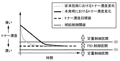
図6は、第1実施形態に係るトナー補給制御方法について説明する図である。
図示のように、トナー補給制御装置100は、トナー濃度目標値から所定の値だけ異なる濃度を補給制御閾値とする。具体的には、トナー補給制御装置100は、トナー濃度目標値から所定の濃度だけ濃い値を第1の補給制御閾値(1)に、トナー濃度目標値から所定の濃度だけ薄い値を第2の補給制御閾値(2)に設定する。このとき、トナー濃度とトナー濃度目標値との差が、補給制御閾値とトナー濃度目標値との差よりも大きい場合(すなわち、図6の定量制御区間)には、トナー補給制御装置100は、露光装置8から入力される出力画像のピクセル数から所定の時間間隔でトナー消費量を算出し、算出したトナー消費量に所定の補給量を加算した分だけトナー補給装置70によりトナー補給を行う(以下、「定量制御法」という)。
FIG. 6 is a diagram illustrating a toner replenishment control method according to the first embodiment.
As shown in the figure, the toner
トナー濃度とトナー補給量は比例関係にあるため、図示のように、トナー濃度は略一定勾配でトナー濃度目標値に近づくことになる。これにより、トナー濃度とトナー濃度目標値との差が大きくなっても、印刷頁間又は頁内の大きな画像濃度変化の発生を抑制することができる。 Since the toner density and the toner replenishment amount are in a proportional relationship, as shown in the figure, the toner density approaches the toner density target value with a substantially constant gradient. Thereby, even if the difference between the toner density and the toner density target value becomes large, it is possible to suppress the occurrence of a large change in image density between printed pages or within a page.
一方、トナー濃度とトナー濃度目標値との差が、補給制御閾値とトナー濃度目標値との差以下の場合(すなわち、図6のPID制御区間)には、トナー補給制御装置100は、露光装置8から入力される出力画像のピクセル数から所定の時間間隔でトナー消費量を算出し、算出したトナー消費量にPID制御で算出した補給量を加算した分だけトナー補給装置70によりトナー補給を行い、トナー濃度をトナー濃度目標値に近づける(以下、「PID制御法」という)。
On the other hand, when the difference between the toner density and the toner density target value is equal to or smaller than the difference between the supply control threshold value and the toner density target value (that is, the PID control section in FIG. 6), the toner
図7は、定量制御のみを継続した場合のトナー濃度変化について説明する図である。
図示のように、補給制御閾値を設けずに定量制御のみを行うと、トナー濃度はトナー濃度目標値と一致することなく振動し続けてしまうことがある。このため、トナー濃度とトナー濃度目標値との差が、補給制御閾値とトナー濃度目標値との差よりも小さい場合(すなわち、図6のPID制御区間)には、所定の時間間隔でトナー消費量を算出し、算出したトナー消費量にPID制御で算出した補給量を加算した分だけ補給を行う(PID制御法)。これにより、図6に示したように、トナー濃度をトナー濃度目標値に追従させることができる。
FIG. 7 is a diagram illustrating a change in toner density when only the quantitative control is continued.
As shown in the figure, if only the quantitative control is performed without providing the replenishment control threshold value, the toner density may continue to vibrate without matching the toner density target value. Therefore, when the difference between the toner density and the toner density target value is smaller than the difference between the replenishment control threshold and the toner density target value (that is, the PID control section in FIG. 6), the toner consumption is performed at a predetermined time interval. The amount is calculated, and replenishment is performed by adding the replenishment amount calculated by the PID control to the calculated toner consumption amount (PID control method). As a result, as shown in FIG. 6, the toner density can be made to follow the toner density target value.
図8は、本発明において一時的に単位時間当たりのトナー補給量が変化した場合について説明する図である。
図中の区間Rは、定量制御の際に環境などにより一時的に単位時間当たりのトナー補給量が変化した部分を示す。この場合、図示のように区間Rではトナー濃度の傾きが一時的に変化するが、区間Rを出てトナー補給量が元に戻ったときには再び略一定勾配のトナー濃度変化になる。よって、一時的に単位時間当たりのトナー補給量が変化した場合でも、印刷頁間又は頁内の大きな画像濃度変化が発生することはない。
FIG. 8 is a diagram illustrating a case where the toner supply amount per unit time is temporarily changed in the present invention.
A section R in the figure shows a portion where the toner replenishment amount per unit time has temporarily changed due to the environment or the like during quantitative control. In this case, as shown in the figure, the gradient of the toner density temporarily changes in the section R. However, when the toner supply amount returns from the section R, the toner density changes again with a substantially constant gradient. Therefore, even when the toner replenishment amount per unit time temporarily changes, a large change in image density between printed pages or within pages does not occur.
図9は、トナー濃度がトナー濃度目標値よりも濃い場合のトナー補給制御方法について説明する図である。
図6の場合とは対照的に、トナー濃度がトナー濃度目標値よりも濃く、定量制御区間にある場合、トナー補給制御装置100は、図9に示すように露光装置8から入力される出力画像のピクセル数から所定の時間間隔でトナー消費量を算出し、算出したトナー消費量に所定のトナー量を減算した分だけトナー補給装置70によりトナー補給を行う(定量制御法)。この場合、算出したトナー消費量にマイナスの補給量を加算した分だけトナー補給を行うことになる。
FIG. 9 is a diagram for explaining a toner replenishment control method when the toner density is higher than the toner density target value.
In contrast to the case of FIG. 6, when the toner density is higher than the toner density target value and is in the quantitative control section, the toner
これにより、トナー濃度がトナー濃度目標値よりも濃い場合においても、図6の場合と同様のトナー補給制御により印刷頁間の濃度ムラを低減することができる。 Thereby, even when the toner density is higher than the toner density target value, density unevenness between printed pages can be reduced by the same toner supply control as in FIG.
図10は、第2実施形態に係るトナー補給制御方法について説明する図である。
前記第1実施形態では、トナー濃度検知手段によるトナー濃度の検知結果にノイズが入るとトナー濃度が補給制御閾値を行き来することになり、トナー補給制御装置100により定量制御法とPID制御法の切り替えが頻繁に行われる。このとき、PID制御法では使用するパラメータによっては過去のトナー濃度とトナー濃度目標値の差の累積値を用いる積分処理において累積値が溜まらなくなるため、トナー濃度がトナー濃度目標値に近づきにくくなる。
FIG. 10 is a diagram illustrating a toner supply control method according to the second embodiment.
In the first embodiment, when noise is detected in the toner density detection result by the toner density detecting means, the toner density goes back and forth between the supply control thresholds, and the toner
そこで、第2実施形態では4つの補給制御閾値を設ける。
図10において、トナー補給制御装置100は、トナー濃度目標値から所定の濃度だけ濃い又は薄い4つの値を第1〜第4の補給制御閾値(1)〜(4)とする。ここで、第3の補給制御閾値(3) > 第1の補給制御閾値(1) > トナー濃度目標値 > 第2の補給制御閾値(2) > 第4の補給制御閾値(4) の関係がある。
Therefore, in the second embodiment, four supply control threshold values are provided.
In FIG. 10, the toner
このとき、トナー補給制御装置100は以下の動作を実行する。
・トナー濃度とトナー濃度目標値との差が、第2の又は第1の補給制御閾値(2)又は(1)とトナー濃度目標値との差よりも大きい場合には、露光装置8から入力される出力画像のピクセル数から所定の時間間隔でトナー消費量を算出する(定量制御法)。
・トナー濃度とトナー濃度目標値との差が、第2の又は第1の補給制御閾値(2)又は(1)とトナー濃度目標値との差以下の場合には、PID制御によりトナー濃度をトナー濃度目標値に近づけるために所要のトナー補給量を算出する(PID制御法)。
・ただし、トナー濃度が、第1の補給制御閾値(1)よりも低い濃度側から第1の補給制御閾値(1)を超えた場合に、PID制御法から定量制御法に切り替えず、トナー濃度が、第3の補給制御閾値(3)よりも低い濃度側から第3の補給制御閾値(3)をさらに超えた場合に、PID制御法から定量制御法に切り替えてトナー補給量を算出する。
・また、トナー濃度が、第2の補給制御閾値(2)よりも高い濃度側から第2の補給制御閾値(2)を超えた場合に、PID制御法から定量制御法に切り替えず、トナー濃度が、第4の補給制御閾値(4)よりも高い濃度側から第4の補給制御閾値(4)をさらに超えた場合に、PID制御法から定量制御法に切り替えてトナー補給量を算出する。
その後、トナー補給制御装置100は、算出したトナー補給量だけトナー補給装置70によりトナー補給を行う。
At this time, the toner
When the difference between the toner density and the toner density target value is larger than the difference between the second or first supply control threshold (2) or (1) and the toner density target value, input from the
If the difference between the toner density and the toner density target value is less than or equal to the difference between the second or first supply control threshold (2) or (1) and the toner density target value, the toner density is controlled by PID control. In order to approach the toner density target value, a required toner replenishment amount is calculated (PID control method).
However, when the toner density exceeds the first supply control threshold (1) from the density side lower than the first supply control threshold (1), the toner density is not switched from the PID control method to the quantitative control method. However, when the third supply control threshold value (3) is further exceeded from the density side lower than the third supply control threshold value (3), the toner supply amount is calculated by switching from the PID control method to the quantitative control method.
In addition, when the toner density exceeds the second supply control threshold (2) from the higher density side than the second supply control threshold (2), the toner density is not switched from the PID control method to the quantitative control method. However, when the fourth supply control threshold (4) is further exceeded from the density side higher than the fourth supply control threshold (4), the toner supply amount is calculated by switching from the PID control method to the quantitative control method.
Thereafter, the toner
よって、トナー濃度が、第2の補給制御閾値(2)よりも高い濃度側から第2の補給制御閾値(2)を超えた場合、PID制御法から定量制御法に切り替えず、第2の補給制御閾値(2)及び第4の補給制御閾値(4)の間の区間ではPID制御法を続行する。また、トナー濃度が、第1の補給制御閾値(1)よりも低い濃度側から第1の補給制御閾値(1)を超えた場合、PID制御法から定量制御法に切り替えず、第1の補給制御閾値(1)及び第3の補給制御閾値(3)の間の区間ではPID制御法を続行する。言い換えれば、第1の補給制御閾値(1)及び第2の補給制御閾値(2)によって画一的にPID制御法と定量制御法を区別せず、PID制御区間に幅を持たせている。第2の補給制御閾値(2)と第4の補給制御閾値(4)の間の区間と、第1の補給制御閾値(1)と第3の補給制御閾値(3)の間の区間では、PID制御法と定量制御法の両方が行われる。 Therefore, when the toner density exceeds the second supply control threshold (2) from the higher density side than the second supply control threshold (2), the second supply is not switched from the PID control method to the quantitative control method. In the section between the control threshold (2) and the fourth supply control threshold (4), the PID control method is continued. When the toner density exceeds the first supply control threshold (1) from the lower density side than the first supply control threshold (1), the first supply is not switched from the PID control method to the quantitative control method. In the section between the control threshold (1) and the third supply control threshold (3), the PID control method is continued. In other words, the PID control method and the quantitative control method are not uniformly distinguished by the first supply control threshold value (1) and the second supply control threshold value (2), and the PID control section has a width. In the section between the second supply control threshold (2) and the fourth supply control threshold (4) and in the section between the first supply control threshold (1) and the third supply control threshold (3), Both the PID control method and the quantitative control method are performed.
以上のように4つの閾値を設けることで、トナー濃度の検知結果にノイズが入ったときに制御装置により定量制御法とPID制御法の切り替えが頻繁に行われることが抑えられる。よって、積分処理で用いる過去のトナー濃度とトナー濃度目標値の差を累積しやすくなり、トナー濃度をトナー濃度目標値に一致させやすくなる。 By providing the four threshold values as described above, it is possible to suppress frequent switching between the quantitative control method and the PID control method by the control device when noise is included in the toner density detection result. Therefore, the difference between the past toner density used in the integration process and the toner density target value can be easily accumulated, and the toner density can be easily matched with the toner density target value.
図11は、第3実施形態に係るトナー補給制御方法について説明する図である。
図示のように、トナー補給量に変化がない場合(図中左側の点線)、トナー濃度グラフの傾きは定量制御によって一定となる。一方、単位時間当たりのトナー補給量が変化した場合(図中右側の点線)、トナー補給量が変化する区間R内におけるトナー濃度グラフの傾きは区間R外と異なり、区間Rから出るときに再び区間R外での傾きに一致する。また、トナー濃度がトナー濃度目標値に到達する時間は、トナー補給量に変化がない場合と比べて遅くなる。
FIG. 11 is a diagram illustrating a toner replenishment control method according to the third embodiment.
As shown in the figure, when there is no change in the toner replenishment amount (dotted line on the left side in the figure), the slope of the toner density graph becomes constant by quantitative control. On the other hand, when the toner replenishment amount per unit time has changed (dotted line on the right side in the figure), the slope of the toner density graph in the section R where the toner replenishment amount changes is different from the outside of the section R, and again when the toner leaves the section R It corresponds to the slope outside the section R. Further, the time for the toner density to reach the toner density target value is delayed as compared with the case where there is no change in the toner replenishment amount.
そこで、第3実施形態では、トナー補給制御装置100は、所定の時間間隔でトナー濃度の変化量からトナー補給量の多寡を判断し、基準値より多い場合には算出したトナー補給量に1未満の値を乗算し、基準値以下の場合には算出したトナー補給量に1以上の値を乗算する。図中の縦の破線は、当該所定の時間間隔で行う補給量補正タイミングを示している。この例では、区間R内でトナー補給量を2回増大補正している。
Therefore, in the third embodiment, the toner
以上の制御を行うことによって、トナー補給量が環境等により変化した場合に、トナー濃度がトナー濃度目標値に達するまでの時間を補給量変化がない理想的な場合に近づけることができる。後述の第4実施形態と比較して、本実施形態では理想的な補給量変化に近づくスピードは遅いが、緩やかな補正を行うことによって頁間のトナー濃度差は小さくなる。 By performing the above control, when the toner replenishment amount changes due to the environment or the like, the time until the toner density reaches the toner density target value can be made closer to an ideal case where there is no change in the replenishment amount. Compared to a fourth embodiment described later, in this embodiment, the speed of approaching an ideal supply amount change is slower, but the toner density difference between pages is reduced by performing a gradual correction.
図12は、第4実施形態に係るトナー補給制御方法について説明する図である。
前記第3実施形態と同様に、定量制御時に環境等のために単位時間当たりのトナー補給量が変化した場合(図中右側の点線)、トナー濃度がトナー濃度目標値に到達する時間は補給量変化がない場合(図中左側の点線)と比べて異なってしまう。この課題について、第4実施形態では、トナー補給制御装置100は、所定の時間間隔でトナー濃度グラフの傾き(X)を算出し、その傾き(X)と補給量変化がない場合の理想的な傾き(Y)との比をトナー補給量に乗算する。この場合、傾き(Y)と傾き(X)の比をとり、比は1より大きい値となる。図中の縦の破線は、当該所定の時間間隔で行う補給量補正タイミングを示している。この例では、区間R内でトナー補給量を1回増大補正して、トナー濃度グラフの傾きを区間R外での傾きに略一致させている。
FIG. 12 is a diagram illustrating a toner replenishment control method according to the fourth embodiment.
As in the third embodiment, when the toner replenishment amount per unit time changes due to the environment or the like during quantitative control (the dotted line on the right side in the figure), the time for the toner concentration to reach the toner concentration target value is the replenishment amount. This is different from the case where there is no change (the dotted line on the left side in the figure). With respect to this problem, in the fourth embodiment, the toner
以上の処理を行うことによって、図12に示すように、トナー補給量が変化する区間Rが長くなっても、トナー濃度の傾きが変化した後に初めてトナー補給量の補正を行ったときに、トナー濃度グラフの傾きを区間R外での理想的な傾きに戻すことができる。 By performing the above processing, as shown in FIG. 12, even when the section R in which the toner replenishment amount changes becomes long, the toner replenishment amount is corrected for the first time after the inclination of the toner density is changed. The slope of the density graph can be returned to the ideal slope outside the section R.
前記第3実施形態と比較して、単位時間当たりのトナー補給量が大きく変化した後にトナー補給量が元に戻ると、トナー濃度変化量が大きくなる可能性があるが、トナー濃度グラフの傾きを迅速に理想的な傾きにすることができる。 Compared with the third embodiment, if the toner replenishment amount returns to the original value after the toner replenishment amount per unit time has changed significantly, the toner density change amount may increase. The ideal tilt can be quickly achieved.
図13は、第5実施形態に係るトナー補給制御方法について説明する図である。
図示のように、前記第4実施形態ではトナー濃度の傾きが急になる箇所が生じ得る。そこで、第5実施形態では、トナー補給制御装置100は、前記第4実施形態と同様に理想的な傾き(Y)とトナー濃度グラフの傾き(X)の比を求め、これを補給量に乗算するが、求める傾きの比に上限及び下限を設定する。これにより、図示のように、トナー濃度は前記第4実施形態と同様にトナー補給制御を行った場合よりも緩やかに変化する。
FIG. 13 is a diagram illustrating a toner replenishment control method according to the fifth embodiment.
As shown in the figure, in the fourth embodiment, there may be a portion where the gradient of the toner density is steep. Therefore, in the fifth embodiment, the toner
以上の制御により、トナー濃度がトナー濃度目標値に近づく時間は、第4実施形態と同様に制御を行った場合よりも遅くなるが、単位時間当たりのトナー補給量が大きく変化した後にトナー補給量が元に戻った場合でも、急激なトナー濃度変化を防ぐことができる。 With the above control, the time when the toner concentration approaches the toner concentration target value is slower than when the control is performed as in the fourth embodiment, but the toner replenishment amount after the toner replenishment amount per unit time greatly changes. Even when the toner returns to its original state, it is possible to prevent a sudden change in toner density.
図14は、トナー濃度目標値が変更された場合のトナー濃度変化について説明する図である。
本発明では、トナー濃度目標値が変更された場合などに、それまで行っていたトナー補給制御方法が切り替わることがある。図中の縦の破線が示すタイミングでトナー濃度目標値が変更されている。例えば、初めのPID制御区間において積分処理に用いるトナー濃度とトナー濃度目標値の差の累積値(以下、「I項」という)が残っている状態で、トナー濃度グラフは縦の破線を越えて変更されたトナー濃度目標値での定量制御区間に入り、その後再度PID制御区間に入る。このとき、I項を含めてトナー補給制御を行うため、トナー濃度グラフの傾きが急になったり、トナー濃度がトナー濃度目標値よりも高い値になったりすることがある。
FIG. 14 is a diagram illustrating toner density change when the toner density target value is changed.
In the present invention, when the toner density target value is changed, the toner replenishment control method performed so far may be switched. The toner density target value is changed at the timing indicated by the vertical broken line in the figure. For example, the toner density graph exceeds the vertical broken line in the state where the cumulative value (hereinafter referred to as “I term”) of the difference between the toner density used for integration processing and the toner density target value remains in the first PID control section. The process enters the quantitative control section with the changed toner density target value, and then enters the PID control section again. At this time, since the toner replenishment control including the I term is performed, the slope of the toner density graph may become steep or the toner density may become higher than the toner density target value.
図15は、第6実施形態に係るトナー補給制御方法について説明する図である。
図14のような問題を解決するために、トナー濃度目標値が変更されたとき、トナー補給制御装置100は、変更前のPID制御区間において積分処理に用いたトナー濃度とトナー濃度目標値の差の累積値(I項)をクリアする。
FIG. 15 is a diagram illustrating a toner replenishment control method according to the sixth embodiment.
In order to solve the problem as shown in FIG. 14, when the toner density target value is changed, the toner
図15に示すように、以上の処理によって、トナー濃度グラフが再度PID制御区間に入った際にはI項による影響がなく、トナー濃度はトナー濃度目標値に緩やかに近づくことになる。 As shown in FIG. 15, when the toner density graph enters the PID control section again by the above process, the I term is not affected, and the toner density gradually approaches the toner density target value.
1 画像形成装置
3 感光体(潜像担持体)
8 露光装置(潜像形成手段)
6 現像装置
70 トナー補給装置
100 トナー補給制御装置
1
8. Exposure device (latent image forming means)
6 Developing
Claims (6)
前記トナー補給制御装置は、トナー濃度目標値から所定の濃度だけ濃い値を第1の補給制御閾値、前記トナー濃度目標値から所定の濃度だけ薄い値を第2の補給制御閾値として設定し、
前記トナー濃度と前記トナー濃度目標値との差が、前記第2の又は第1の補給制御閾値と前記トナー濃度目標値との差よりも大きい場合、前記トナー補給制御装置は、出力画像のピクセル数を基にトナー消費量を算出し、算出した前記トナー消費量に所定量を加算又は減算して前記トナー補給量を算出し(定量制御法)、
前記トナー濃度と前記トナー濃度目標値との差が、前記第2の又は第1の補給制御閾値と前記トナー濃度目標値との差以下の場合、前記トナー補給制御装置は、PID制御により前記トナー濃度を前記トナー濃度目標値に近づけるために所要の前記トナー補給量を算出する(PID制御法)画像形成装置。 A latent image carrier, latent image forming means for forming a latent image on the latent image carrier based on image information, a developing device for developing the latent image on the latent image carrier using toner, and Toner density detection means for detecting the toner density in the developing device, toner supply control apparatus to which image information from the latent image forming means and toner density information from the toner density detection means are input, and the toner supply control apparatus A toner replenishing device that replenishes the toner replenishment amount calculated in
The toner replenishment control device sets a value that is darker than the toner density target value by a predetermined density as a first replenishment control threshold, and a value that is lighter than the toner density target value by a predetermined density as a second replenishment control threshold.
When the difference between the toner density and the toner density target value is larger than the difference between the second or first supply control threshold value and the toner density target value, the toner supply control device outputs a pixel of the output image. A toner consumption amount is calculated based on the number, and a predetermined amount is added to or subtracted from the calculated toner consumption amount to calculate the toner replenishment amount (quantitative control method);
When the difference between the toner density and the toner density target value is equal to or less than the difference between the second or first supply control threshold and the toner density target value, the toner supply control device performs the toner control by PID control. An image forming apparatus that calculates a required toner replenishment amount in order to bring the density close to the toner density target value (PID control method).
前記トナー補給制御装置は、トナー濃度目標値から所定の濃度だけ濃い値を第1の補給制御閾値、前記トナー濃度目標値から所定の濃度だけ薄い値を第2の補給制御閾値、前記第1の補給制御閾値から所定の濃度だけ濃い値を第3の補給制御閾値、前記第2の補給制御閾値から所定の濃度だけ薄い値を第4の補給制御閾値として設定し、
前記トナー濃度と前記トナー濃度目標値との差が、前記第2の又は第1の補給制御閾値と前記トナー濃度目標値との差よりも大きい場合、前記トナー補給制御装置は、出力画像のピクセル数を基にトナー消費量を算出し、算出した前記トナー消費量に所定量を加算又は減算して前記トナー補給量を算出し(定量制御法)、
前記トナー濃度と前記トナー濃度目標値との差が、前記第2の又は第1の補給制御閾値と前記トナー濃度目標値との差以下の場合、前記トナー補給制御装置は、PID制御により前記トナー濃度を前記トナー濃度目標値に近づけるために所要の前記トナー補給量を算出し(PID制御法)、
前記トナー濃度が、前記第1の補給制御閾値よりも低い濃度側から前記第1の補給制御閾値を超えた場合に、前記トナー補給制御装置は前記PID制御法から前記定量制御法に切り替えず、前記トナー濃度が、前記第3の補給制御閾値よりも低い濃度側から前記第3の補給制御閾値をさらに超えた場合に、前記トナー補給制御装置は前記PID制御法から前記定量制御法に切り替えて前記トナー補給量を算出し、
前記トナー濃度が、前記第2の補給制御閾値よりも高い濃度側から前記第2の補給制御閾値を超えた場合に、前記トナー補給制御装置は前記PID制御法から前記定量制御法に切り替えず、前記トナー濃度が、前記第4の補給制御閾値よりも高い濃度側から前記第4の補給制御閾値をさらに超えた場合に、前記トナー補給制御装置は前記PID制御法から前記定量制御法に切り替えて前記トナー補給量を算出する画像形成装置。 A latent image carrier, latent image forming means for forming a latent image on the latent image carrier based on image information, a developing device for developing the latent image on the latent image carrier using toner, and Toner density detection means for detecting the toner density in the developing device, toner supply control apparatus to which image information from the latent image forming means and toner density information from the toner density detection means are input, and the toner supply control apparatus A toner replenishing device that replenishes the toner replenishment amount calculated in
The toner replenishment control device has a value that is higher by a predetermined density than a toner density target value as a first replenishment control threshold, a value that is lower than the toner density target value by a predetermined density as a second replenishment control threshold, and the first A value darker than the supply control threshold by a predetermined concentration is set as a third supply control threshold, and a value lower than the second supply control threshold by a predetermined concentration is set as a fourth supply control threshold.
When the difference between the toner density and the toner density target value is larger than the difference between the second or first supply control threshold value and the toner density target value, the toner supply control device outputs a pixel of the output image. A toner consumption amount is calculated based on the number, and a predetermined amount is added to or subtracted from the calculated toner consumption amount to calculate the toner replenishment amount (quantitative control method);
When the difference between the toner density and the toner density target value is equal to or less than the difference between the second or first supply control threshold and the toner density target value, the toner supply control device performs the toner control by PID control. Calculate the required toner replenishment amount in order to bring the density close to the toner density target value (PID control method),
When the toner density exceeds the first supply control threshold from the density side lower than the first supply control threshold, the toner supply control device does not switch from the PID control method to the quantitative control method, When the toner density further exceeds the third supply control threshold from the density side lower than the third supply control threshold, the toner supply control device switches from the PID control method to the quantitative control method. Calculating the toner replenishment amount;
When the toner concentration exceeds the second supply control threshold from the higher density side than the second supply control threshold, the toner supply control device does not switch from the PID control method to the quantitative control method, When the toner density further exceeds the fourth supply control threshold from the higher density side than the fourth supply control threshold, the toner supply control device switches from the PID control method to the quantitative control method. An image forming apparatus for calculating the toner replenishment amount.
Priority Applications (1)
| Application Number | Priority Date | Filing Date | Title |
|---|---|---|---|
| JP2013008253A JP6032023B2 (en) | 2013-01-21 | 2013-01-21 | Image forming apparatus |
Applications Claiming Priority (1)
| Application Number | Priority Date | Filing Date | Title |
|---|---|---|---|
| JP2013008253A JP6032023B2 (en) | 2013-01-21 | 2013-01-21 | Image forming apparatus |
Publications (2)
| Publication Number | Publication Date |
|---|---|
| JP2014139611A JP2014139611A (en) | 2014-07-31 |
| JP6032023B2 true JP6032023B2 (en) | 2016-11-24 |
Family
ID=51416350
Family Applications (1)
| Application Number | Title | Priority Date | Filing Date |
|---|---|---|---|
| JP2013008253A Active JP6032023B2 (en) | 2013-01-21 | 2013-01-21 | Image forming apparatus |
Country Status (1)
| Country | Link |
|---|---|
| JP (1) | JP6032023B2 (en) |
Family Cites Families (5)
| Publication number | Priority date | Publication date | Assignee | Title |
|---|---|---|---|---|
| JPH04269778A (en) * | 1991-02-26 | 1992-09-25 | Fujitsu Ltd | Toner concentration controlling method |
| JP2003131439A (en) * | 2001-10-22 | 2003-05-09 | Canon Inc | Image forming device |
| JP4914243B2 (en) * | 2007-02-26 | 2012-04-11 | 京セラミタ株式会社 | Development device |
| JP2010072156A (en) * | 2008-09-17 | 2010-04-02 | Ricoh Co Ltd | Image forming apparatus, computer, image forming system, method of changing toner concentration adjustment parameter, method of transmitting toner concentration adjustment parameter, and program |
| JP5377341B2 (en) * | 2009-04-23 | 2013-12-25 | キヤノン株式会社 | Image forming apparatus |
-
2013
- 2013-01-21 JP JP2013008253A patent/JP6032023B2/en active Active
Also Published As
| Publication number | Publication date |
|---|---|
| JP2014139611A (en) | 2014-07-31 |
Similar Documents
| Publication | Publication Date | Title |
|---|---|---|
| JP6119246B2 (en) | Image forming apparatus | |
| JP4480066B2 (en) | Image forming apparatus | |
| US9977361B2 (en) | Image forming apparatus and image forming system | |
| JP6264643B2 (en) | Image forming apparatus | |
| JP6111780B2 (en) | Image forming apparatus | |
| JP6270138B2 (en) | Image forming apparatus | |
| JP5979324B2 (en) | Image forming apparatus | |
| JP6500616B2 (en) | Image forming device | |
| JP2008026747A (en) | Image forming apparatus | |
| JP2008020818A (en) | Image forming apparatus and image stabilization method | |
| US10203642B2 (en) | Image forming apparatus and a recording medium for determining image defects based on development current | |
| JP2009276517A (en) | Image forming apparatus | |
| JP2016090860A (en) | Image forming apparatus | |
| JP4887949B2 (en) | Image forming apparatus and toner density control method | |
| JP2015166846A (en) | Control apparatus which determines exposure energy to be used for image formation, and image forming apparatus using the same | |
| JP6032023B2 (en) | Image forming apparatus | |
| JP2017198849A (en) | Image forming apparatus | |
| JP5028855B2 (en) | Image forming apparatus | |
| US10558141B2 (en) | Image forming apparatus, developing device, and developer liquid-level detection program | |
| JP5982784B2 (en) | Image forming apparatus | |
| JP6863327B2 (en) | Image forming device | |
| JP2018081206A (en) | Image forming apparatus | |
| JP2017021233A (en) | Image formation device | |
| JP2022178033A (en) | image forming device | |
| JP2015001658A (en) | Image formation device and image formation method |
Legal Events
| Date | Code | Title | Description |
|---|---|---|---|
| A621 | Written request for application examination |
Free format text: JAPANESE INTERMEDIATE CODE: A621 Effective date: 20151210 |
|
| TRDD | Decision of grant or rejection written | ||
| A977 | Report on retrieval |
Free format text: JAPANESE INTERMEDIATE CODE: A971007 Effective date: 20160921 |
|
| A01 | Written decision to grant a patent or to grant a registration (utility model) |
Free format text: JAPANESE INTERMEDIATE CODE: A01 Effective date: 20160927 |
|
| A61 | First payment of annual fees (during grant procedure) |
Free format text: JAPANESE INTERMEDIATE CODE: A61 Effective date: 20161010 |
|
| R151 | Written notification of patent or utility model registration |
Ref document number: 6032023 Country of ref document: JP Free format text: JAPANESE INTERMEDIATE CODE: R151 |