JP7343252B2 - Propulsion and braking system using clutch - Google Patents
Propulsion and braking system using clutch Download PDFInfo
- Publication number
- JP7343252B2 JP7343252B2 JP2022528588A JP2022528588A JP7343252B2 JP 7343252 B2 JP7343252 B2 JP 7343252B2 JP 2022528588 A JP2022528588 A JP 2022528588A JP 2022528588 A JP2022528588 A JP 2022528588A JP 7343252 B2 JP7343252 B2 JP 7343252B2
- Authority
- JP
- Japan
- Prior art keywords
- clutch
- rotational speed
- driven body
- operating pressure
- control unit
- Prior art date
- Legal status (The legal status is an assumption and is not a legal conclusion. Google has not performed a legal analysis and makes no representation as to the accuracy of the status listed.)
- Active
Links
- 230000006698 induction Effects 0.000 claims description 143
- 230000001105 regulatory effect Effects 0.000 claims description 82
- 239000010687 lubricating oil Substances 0.000 claims description 55
- 230000001276 controlling effect Effects 0.000 claims description 49
- 230000006870 function Effects 0.000 claims description 49
- 230000002441 reversible effect Effects 0.000 claims description 49
- 230000008859 change Effects 0.000 claims description 25
- 230000007423 decrease Effects 0.000 claims description 19
- 230000009467 reduction Effects 0.000 claims description 15
- 230000001052 transient effect Effects 0.000 claims description 15
- 238000000034 method Methods 0.000 claims description 13
- 238000011084 recovery Methods 0.000 claims description 11
- 230000003247 decreasing effect Effects 0.000 claims description 9
- 230000008569 process Effects 0.000 claims description 4
- 230000005540 biological transmission Effects 0.000 claims description 2
- 238000005461 lubrication Methods 0.000 claims 2
- 239000003921 oil Substances 0.000 claims 2
- 238000002485 combustion reaction Methods 0.000 description 88
- 239000007858 starting material Substances 0.000 description 33
- 239000003638 chemical reducing agent Substances 0.000 description 31
- 230000009977 dual effect Effects 0.000 description 27
- 238000006243 chemical reaction Methods 0.000 description 16
- 230000001360 synchronised effect Effects 0.000 description 10
- 238000001514 detection method Methods 0.000 description 7
- 238000012806 monitoring device Methods 0.000 description 6
- 238000005259 measurement Methods 0.000 description 5
- 239000000314 lubricant Substances 0.000 description 4
- 230000001141 propulsive effect Effects 0.000 description 4
- 238000004891 communication Methods 0.000 description 3
- 239000000446 fuel Substances 0.000 description 3
- 238000007726 management method Methods 0.000 description 3
- 239000000470 constituent Substances 0.000 description 2
- 238000001816 cooling Methods 0.000 description 2
- 230000008878 coupling Effects 0.000 description 2
- 238000010168 coupling process Methods 0.000 description 2
- 238000005859 coupling reaction Methods 0.000 description 2
- 230000000694 effects Effects 0.000 description 2
- 238000002360 preparation method Methods 0.000 description 2
- 230000001172 regenerating effect Effects 0.000 description 2
- 230000004913 activation Effects 0.000 description 1
- 230000008901 benefit Effects 0.000 description 1
- 238000012937 correction Methods 0.000 description 1
- 238000011161 development Methods 0.000 description 1
- 230000005611 electricity Effects 0.000 description 1
- 238000002347 injection Methods 0.000 description 1
- 239000007924 injection Substances 0.000 description 1
- 238000009434 installation Methods 0.000 description 1
- 238000012423 maintenance Methods 0.000 description 1
- 238000010295 mobile communication Methods 0.000 description 1
- 238000012986 modification Methods 0.000 description 1
- 230000004048 modification Effects 0.000 description 1
- 239000003380 propellant Substances 0.000 description 1
- 230000008439 repair process Effects 0.000 description 1
- 238000000926 separation method Methods 0.000 description 1
- 238000006467 substitution reaction Methods 0.000 description 1
Images


Classifications
-
- B—PERFORMING OPERATIONS; TRANSPORTING
- B63—SHIPS OR OTHER WATERBORNE VESSELS; RELATED EQUIPMENT
- B63H—MARINE PROPULSION OR STEERING
- B63H23/00—Transmitting power from propulsion power plant to propulsive elements
- B63H23/30—Transmitting power from propulsion power plant to propulsive elements characterised by use of clutches
-
- B—PERFORMING OPERATIONS; TRANSPORTING
- B63—SHIPS OR OTHER WATERBORNE VESSELS; RELATED EQUIPMENT
- B63H—MARINE PROPULSION OR STEERING
- B63H23/00—Transmitting power from propulsion power plant to propulsive elements
- B63H23/32—Other parts
- B63H23/34—Propeller shafts; Paddle-wheel shafts; Attachment of propellers on shafts
- B63H23/35—Shaft braking or locking, i.e. means to slow or stop the rotation of the propeller shaft or to prevent the shaft from initial rotation
-
- B—PERFORMING OPERATIONS; TRANSPORTING
- B63—SHIPS OR OTHER WATERBORNE VESSELS; RELATED EQUIPMENT
- B63H—MARINE PROPULSION OR STEERING
- B63H21/00—Use of propulsion power plant or units on vessels
- B63H21/12—Use of propulsion power plant or units on vessels the vessels being motor-driven
- B63H21/17—Use of propulsion power plant or units on vessels the vessels being motor-driven by electric motor
-
- B—PERFORMING OPERATIONS; TRANSPORTING
- B63—SHIPS OR OTHER WATERBORNE VESSELS; RELATED EQUIPMENT
- B63H—MARINE PROPULSION OR STEERING
- B63H21/00—Use of propulsion power plant or units on vessels
- B63H21/22—Use of propulsion power plant or units on vessels the propulsion power units being controlled from exterior of engine room, e.g. from navigation bridge; Arrangements of order telegraphs
-
- B—PERFORMING OPERATIONS; TRANSPORTING
- B63—SHIPS OR OTHER WATERBORNE VESSELS; RELATED EQUIPMENT
- B63H—MARINE PROPULSION OR STEERING
- B63H23/00—Transmitting power from propulsion power plant to propulsive elements
- B63H23/02—Transmitting power from propulsion power plant to propulsive elements with mechanical gearing
- B63H23/08—Transmitting power from propulsion power plant to propulsive elements with mechanical gearing with provision for reversing drive
-
- F—MECHANICAL ENGINEERING; LIGHTING; HEATING; WEAPONS; BLASTING
- F16—ENGINEERING ELEMENTS AND UNITS; GENERAL MEASURES FOR PRODUCING AND MAINTAINING EFFECTIVE FUNCTIONING OF MACHINES OR INSTALLATIONS; THERMAL INSULATION IN GENERAL
- F16D—COUPLINGS FOR TRANSMITTING ROTATION; CLUTCHES; BRAKES
- F16D48/00—External control of clutches
- F16D48/02—Control by fluid pressure
-
- G—PHYSICS
- G08—SIGNALLING
- G08B—SIGNALLING OR CALLING SYSTEMS; ORDER TELEGRAPHS; ALARM SYSTEMS
- G08B21/00—Alarms responsive to a single specified undesired or abnormal condition and not otherwise provided for
- G08B21/18—Status alarms
- G08B21/182—Level alarms, e.g. alarms responsive to variables exceeding a threshold
-
- F—MECHANICAL ENGINEERING; LIGHTING; HEATING; WEAPONS; BLASTING
- F16—ENGINEERING ELEMENTS AND UNITS; GENERAL MEASURES FOR PRODUCING AND MAINTAINING EFFECTIVE FUNCTIONING OF MACHINES OR INSTALLATIONS; THERMAL INSULATION IN GENERAL
- F16D—COUPLINGS FOR TRANSMITTING ROTATION; CLUTCHES; BRAKES
- F16D48/00—External control of clutches
- F16D48/02—Control by fluid pressure
- F16D2048/0227—Source of pressure producing the clutch engagement or disengagement action within a circuit; Means for initiating command action in power assisted devices
-
- F—MECHANICAL ENGINEERING; LIGHTING; HEATING; WEAPONS; BLASTING
- F16—ENGINEERING ELEMENTS AND UNITS; GENERAL MEASURES FOR PRODUCING AND MAINTAINING EFFECTIVE FUNCTIONING OF MACHINES OR INSTALLATIONS; THERMAL INSULATION IN GENERAL
- F16D—COUPLINGS FOR TRANSMITTING ROTATION; CLUTCHES; BRAKES
- F16D48/00—External control of clutches
- F16D48/02—Control by fluid pressure
- F16D2048/0257—Hydraulic circuit layouts, i.e. details of hydraulic circuit elements or the arrangement thereof
- F16D2048/0266—Actively controlled valves between pressure source and actuation cylinder
Description
本発明は、クラッチを用いた推進及び制動システムに関し、より詳細には、船舶の推進及び制動に使用される電力変換装置(power converter)、可変ピッチプロペラ(CPP、Controllable Pitch Propeller)、及び摩擦ブレーキ(friction brake)なしでも経済的かつ効率的な推進及び制動が可能であり、車両にも適用が可能なクラッチを用いた推進及び制動システムに関する。 The present invention relates to a propulsion and braking system using a clutch, and more specifically to a power converter, a controllable pitch propeller (CPP), and a friction brake used for propulsion and braking of a ship. The present invention relates to a propulsion and braking system using a clutch that enables economical and efficient propulsion and braking even without a friction brake, and which can be applied to vehicles.
回転力を推進力に変える装置として使用されるプロペラ(propeller)は、船舶の推進及び制動のために使用されるが、プロペラは、軸(shaft)の終端に設けられる羽根(blade)のピッチ(pitch)が調整可能な可変ピッチプロペラと、羽根のピッチが調整不可能な固定ピッチプロペラ(FPP、Fixed Pitch Propeller)とに分けられる。 A propeller is used as a device to convert rotational force into propulsive force, and is used for propulsion and braking of ships. There are two types of propellers: variable pitch propellers whose blade pitch is adjustable, and fixed pitch propellers (FPP) whose blade pitch is not adjustable.
CPP船舶での推進速度は、軸駆動体の回転速度が一定であっても、プロペラ羽根のピッチ角(angle of pitch)によって変わるが、軸駆動体の回転速度で発生させる力よりプロペラで要求される負荷量が大きい場合、軸駆動体に過負荷が発生されるので、このような現象が発生されないように軸駆動体の回転速度別の出力とプロペラ羽根のピッチ角は連動制御されなければならない。船舶の推進(前進及び後進)及び制動は、軸駆動体の出力と連動制御されるプロペラ羽根のピッチ角調整にて可能であるが、プロペラ羽根のピッチ角を調整するためのシステムが高価であるという短所がある。 The propulsion speed on a CPP ship varies depending on the pitch angle of the propeller blades even if the rotation speed of the shaft drive body is constant, but the force required by the propeller is greater than the force generated by the rotation speed of the shaft drive body. If the load amount is large, overload will occur on the shaft drive body, so to prevent this phenomenon from occurring, the output at each rotation speed of the shaft drive body and the pitch angle of the propeller blades must be controlled in conjunction. . Propulsion (forward and backward) and braking of a ship can be achieved by adjusting the pitch angle of the propeller blades, which are controlled in conjunction with the output of the shaft drive body, but the system for adjusting the pitch angle of the propeller blades is expensive. There is a disadvantage.
FPP船舶での推進速度は、軸駆動体の回転速度によって変わるが、FPPで要求される回転速度別の負荷量は、軸駆動体の回転速度別の出力より小さいように製作される。船舶の推進及び制動は、軸駆動体の回転速度調整及び回転方向調整にて可能であり、高い制動力が必要な場合、摩擦ブレーキをプロペラ軸にさらに設ける。停止及び後進しようとする場合、CPP船舶とは異なり、プロペラを逆回転(reverse rotation)させると良いが、軸駆動体が2行程内燃機関である場合、内燃機関の回転方向を逆回転させることができるので、別の装置が必要でなく、軸駆動体が4行程内燃機関である場合、回転方向を逆回転させることができないので、減速機にプロペラの回転方向転換が可能な機能を有するようにする。プロペラ羽根のピッチ角を調整するためのシステムが必要ないので、製品の値段が低価であるという長所がある。 The propulsion speed of an FPP ship varies depending on the rotational speed of the shaft drive body, and the amount of load required for each rotation speed in FPP is manufactured to be smaller than the output for each rotation speed of the shaft drive body. Propulsion and braking of the ship are possible by adjusting the rotational speed and rotational direction of the shaft drive body, and if a high braking force is required, a friction brake is further provided on the propeller shaft. When trying to stop and go astern, unlike CPP vessels, it is better to reverse rotation the propeller, but if the shaft drive is a two-stroke internal combustion engine, it is not possible to reverse the direction of rotation of the internal combustion engine. If the shaft drive body is a 4-stroke internal combustion engine, the direction of rotation cannot be reversed, so the speed reducer should have a function that allows the direction of rotation of the propeller to be changed. do. Since there is no need for a system to adjust the pitch angle of the propeller blades, the product has the advantage of being inexpensive.
一般に、2行程(2-stroke)内燃機関にて推進する船舶の場合、内燃機関の定格回転速度と全速力(full admission)を出すための船舶のプロペラ回転速度とは同一であるので、減速機が必要でなく、4行程(4-stroke)内燃機関にて推進する船舶の場合、内燃機関の定格回転速度が全速力を出すための船舶のプロペラ回転速度より速いので、減速機が必要である。 Generally, in the case of a ship that is propelled by a 2-stroke internal combustion engine, the rated rotational speed of the internal combustion engine and the rotational speed of the ship's propeller to produce full admission are the same, so the reduction gear is For ships that are not required and are propelled by 4-stroke internal combustion engines, a reduction gear is necessary because the rated rotational speed of the internal combustion engine is faster than the ship's propeller rotational speed for full speed.
電気推進(electric propulsion)船舶の場合、可変速電力変換装置を使用して電動機の回転速度及び回転方向を可変できる場合には、FPPを使用し、正弦波のみを供給する変速の不可能な電力変換装置を使用して、電動機の回転速度及び回転方向を可変できない場合には、CPPを使用する。正弦波のみを供給する変速の不可能な電力変換装置を使用する場合、電動機の回転速度は、極数変換(高速、中速)誘導電動機(induction motor)を使用する。また、可変速電力変換装置、正弦波のみを供給する変速の不可能な電力変換装置の故障に備えて、迂回(bypass)電力供給装置にて電動機に電力が供給され得るように用意する。 In the case of electric propulsion vessels, if the rotational speed and direction of the motor can be varied using a variable speed power converter, FPP is used to provide non-variable power that supplies only sine waves. CPP is used when the rotation speed and rotation direction of the electric motor cannot be varied using a conversion device. When using a non-variable speed power conversion device that supplies only sine waves, the rotational speed of the motor is changed using a pole number conversion (high speed, medium speed) induction motor. In addition, in preparation for a failure of the variable speed power converter or the power converter that cannot change speed and supplies only sine waves, a bypass power supply device is provided so that power can be supplied to the motor.
一方、電気推進船舶では、軸駆動体の回転速度をプロペラの回転速度に合うように減速するための減速機を使用しない船舶と減速機を使用する船舶とに分けることができる。減速機を使用しない船舶において、プロペラの回転速度が100rpmであるとき、電動機の回転速度は、プロペラの回転速度と同一でなければならないので、使用する周波数が60Hzであれば、72pole、50Hzであれば、60poleの電動機を使用する。減速機を使用する船舶において、プロペラの回転速度が100rpmであるとき、使用する周波数によって60Hzでは8pole(900rpm)、50Hzでは6pole(l,000rpm)の電動機を使用すれば、60Hzには9:1、50Hzには10:1の割合の減速機を使用すれば良い。船舶のプロペラ回転速度は、船舶が大型化されるほど低いが、電動機の回転速度をこれに合わせる場合、電動機の直径が大きくなり、値段も高価になるので、一般的に電動機の回転速度をl,000rpm以下とし、プロペラの回転速度で電動機の回転速度を低めるために減速機を使用している。 On the other hand, electric propulsion ships can be divided into ships that do not use a speed reducer to reduce the rotational speed of the shaft drive body to match the rotational speed of the propeller, and ships that use a speed reducer. In a ship that does not use a speed reducer, when the propeller rotation speed is 100 rpm, the motor rotation speed must be the same as the propeller rotation speed, so if the frequency used is 60 Hz, 72 pole, 50 Hz, etc. For example, a 60-pole electric motor is used. In a ship that uses a speed reducer, when the propeller rotation speed is 100 rpm, if a motor with 8 poles (900 rpm) is used at 60 Hz and 6 poles (l,000 rpm) at 50 Hz, depending on the frequency used, the ratio is 9:1 at 60 Hz. , 50Hz, a reduction gear with a ratio of 10:1 may be used. The propeller rotation speed of a ship is lower as the ship becomes larger, but if the rotation speed of the electric motor is adjusted to this speed, the diameter of the electric motor becomes larger and the price becomes higher. ,000 rpm or less, and a reducer is used to reduce the rotation speed of the electric motor with the rotation speed of the propeller.
電気推進船舶の場合、電動機に電力を供給するために使用される電気製品の段階が多くなるほど損失が多くなり、電力変換装置は、冷房装置が設けられた空間で運営されなければならず、高出力製品の場合、装置から発生される熱の冷却のための水冷式冷却器が必要であり、かつ、便宜性に比べて製品の値段が高価であるという短所がある。 For electric propulsion vessels, the more stages of electrical equipment used to power the motors, the more losses there are, and the power conversion equipment must be operated in a space with cooling equipment, and high In the case of an output product, a water-cooled cooler is required to cool the heat generated from the device, and the product is expensive compared to its convenience.
駆動体と被駆動体との間のトルク(動力)を切るか、繋ぐ装置として使用されるクラッチは、2行程内燃機関の場合、始動トルクがプロペラで要求する始動トルクより大きいので、クラッチを使用せず、4行程内燃機関の場合、始動トルクがプロペラで要求する始動トルクより小さいので、内燃機関の始動のためにクラッチが必要である。 A clutch is used as a device to cut off or connect the torque (power) between the driving body and the driven body.In the case of a two-stroke internal combustion engine, a clutch is used because the starting torque is greater than the starting torque required by the propeller. In the case of a four-stroke internal combustion engine, a clutch is required for starting the internal combustion engine because the starting torque is less than the starting torque required by the propeller.
また、クラッチの接続時点は、クラッチの接続の際、軸駆動体のトルクが被駆動体で要求される始動トルクより小さい場合、軸駆動体が停止する現象が発生され得るので、軸駆動体のトルクが被駆動体で要求する始動トルクより大きい時点(回転速度)でクラッチを接続させ、電気推進船舶では、電動機始動トルク調節が可能な可変速電力変換装置を使用して回転速度を調節するが、電動機の始動トルクをプロペラで要求される始動トルクより大きくすれば良いので、電動機と減速機との間には、クラッチを一般的に使用しない。 In addition, when the clutch is connected, if the torque of the shaft drive body is smaller than the starting torque required by the driven body, the shaft drive body may stop. The clutch is engaged when the torque is greater than the starting torque required by the driven body (rotational speed), and in electric propulsion vessels, the rotational speed is adjusted using a variable speed power converter that can adjust the motor starting torque. Generally, a clutch is not used between the electric motor and the reduction gear because the starting torque of the electric motor only needs to be greater than the starting torque required by the propeller.
減速機は、駆動体の回転速度と被駆動体の回転速度とが異なる場合に使用されるが、単一入力-単一出力(single input-single output)減速機は、1つの駆動体に1つの被駆動体が連結されるものであり、被駆動体の要求動力に対比して駆動体を1つにする場合、製品があまりにも大型化されるという問題があるか、運用信頼性増大のために、駆動体の数量増大が必要な場合に使用される多重入力-単一出力(multi input-single output)減速機は、種々の駆動体に1つの被駆動体が連結されるものであって、これらの駆動体間の並列運転前には、同期化過程が先行されなければならない。 A speed reducer is used when the rotational speed of the driving body and the rotational speed of the driven body are different, but a single input-single output (single input-single output) speed reducer is used when the rotational speed of the driving body and the driven body are different. Two driven bodies are connected, and if one driving body is used in comparison to the required power of the driven bodies, there is a problem that the product becomes too large, or it is difficult to increase operational reliability. A multi-input-single-output reducer is used when an increase in the number of driving bodies is required for the purpose of increasing the number of driving bodies, in which one driven body is connected to various driving bodies. Therefore, before parallel operation between these drives, a synchronization process must be preceded.
2台の4行程内燃機関にて推進される2機1軸船のCPPの場合、二重入力-単一出力クラッチ内蔵減速機を使用する。プロペラ羽根のピッチ角を小さく調整して1台の内燃機関にて船舶を低速で運転中の状態で船舶の速度を上げるためには、残りの内燃機関もクラッチ内蔵減速機を介して連結しなければならないが、このときに発生される衝撃トルクを最小化するために、負荷運転中の内燃機関の回転速度と連結しようとする内燃機関の回転速度とを一致させる同期化が必要である。このために、動力を先に伝達している内燃機関の回転速度に合うように連結しようとする内燃機関の回転速度を調速機を介して調整して同期化が完了すれば、連結しようとするクラッチ内蔵減速機のクラッチを接続(engagement)して内燃機関間の並列運転を行った後、羽根のピッチ角を増加させれば良い。 In the case of a two-engine, single-shaft CPP propelled by two four-stroke internal combustion engines, a dual input-single output clutch built-in speed reducer is used. In order to adjust the pitch angle of the propeller blades to a small value and increase the speed of the ship while the ship is operating at low speed with one internal combustion engine, the remaining internal combustion engines must also be connected via a reducer with a built-in clutch. However, in order to minimize the impact torque generated at this time, it is necessary to synchronize the rotational speed of the internal combustion engine during load operation and the rotational speed of the internal combustion engine to be coupled. For this purpose, the rotational speed of the internal combustion engine to be coupled is adjusted via the governor to match the rotational speed of the internal combustion engine that is transmitting power first, and once synchronization is completed, the rotational speed of the internal combustion engine to be coupled is The pitch angle of the blades may be increased after the internal combustion engines are operated in parallel by engaging the clutch of the clutch-incorporated speed reducer.
2台の4行程内燃機関にて推進される2機1軸船のFPPの場合、二重入力-単一出力クラッチ内蔵減速機を使用する。プロペラ羽根のピッチ角を調整できないので、1台の内燃機関にて船舶運転の際、過負荷が発生するので、2台の内燃機関にて低負荷で並列運転を行った後、負荷運転をしなければならない。このために、まず、1台の内燃機関を空回転(idle)状態でクラッチ内蔵減速機のクラッチを接続させた後、残りの内燃機関をクラッチ内蔵減速機を介して連結しなければならないが、このときに発生される衝撃トルクを最小化するために、負荷運転中の内燃機関の回転速度と連結しようとする内燃機関の回転速度とを一致させる同期化が必要である。このために、動力を先に伝達している内燃機関の回転速度に合うように連結しようとする内燃機関の回転速度を調速機を介して調整して同期化が完了すれば、連結しようとするクラッチ内蔵減速機のクラッチを接続して内燃機関間の並列運転を行った後、内燃機関の回転速度を同時に増加させれば良い。 In the case of a two-engine single-shaft FPP propelled by two four-stroke internal combustion engines, a speed reducer with a dual input-single output clutch is used. Since the pitch angle of the propeller blades cannot be adjusted, overload will occur when operating a ship with one internal combustion engine, so two internal combustion engines should be operated in parallel at a low load and then operated under load. There must be. To do this, first, the clutch of the clutch built-in reducer must be connected to one internal combustion engine in an idle state, and then the remaining internal combustion engines must be connected via the clutch built-in speed reducer. In order to minimize the impact torque generated at this time, it is necessary to synchronize the rotational speed of the internal combustion engine during load operation with the rotational speed of the internal combustion engine to be coupled. For this purpose, the rotational speed of the internal combustion engine to be coupled is adjusted via the governor to match the rotational speed of the internal combustion engine that is transmitting power first, and once synchronization is completed, the rotational speed of the internal combustion engine to be coupled is After connecting the clutch of the clutch built-in speed reducer to perform parallel operation between the internal combustion engines, the rotational speeds of the internal combustion engines may be simultaneously increased.
2台の電動機にて推進される2機1軸船のCPPの場合、二重入力-単一出力減速機が使用されるが、このとき、電動機と減速機との間にはクラッチが使用されない。プロペラ羽根のピッチ角を小さく調整して1台の電動機にて船舶を低速で運転中の状態で船舶の速度を上げるためには、残りの電動機を連結しなければならないが、このための電動機間の同期化及び並列運転制御は、可変速電力変換装置を介してなされ、電動機間の並列運転を行った後、羽根のピッチ角を増加させれば良い。二重入力-単一出力減速機と電動機との間にクラッチを使用しない場合、1台の電動機にて船舶を運航すれば、運転されない他の電動機の回転子が回転するようになるが、これは、運転中の電動機の負荷として作用してエネルギー損失を発生させるので、クラッチを設ける場合もある。 In the case of CPP, a two-engine, single-shaft ship propelled by two electric motors, a dual input-single output reducer is used, but at this time, a clutch is not used between the electric motor and the reducer. . In order to adjust the pitch angle of the propeller blades to a small value and increase the speed of the ship while the ship is operating at low speed with one electric motor, the remaining electric motors must be connected, but for this purpose it is necessary to connect the remaining electric motors. Synchronization and parallel operation control are performed via a variable speed power converter, and the pitch angle of the blades may be increased after parallel operation between the electric motors. If a clutch is not used between the dual input-single output reducer and the electric motor, operating the vessel with one electric motor will cause the rotor of the other electric motor that is not in operation to rotate. acts as a load on the motor during operation and causes energy loss, so a clutch may be provided.
2台の電動機にて電気推進される2機1軸船のFPPの場合、二重入力-単一出力減速機が使用されるが、このとき、電動機と減速機との間にはクラッチが使用されない。プロペラ羽根のピッチ角を調整できないので、1台の電動機にて船舶運転の際、過負荷が発生されるので、2台の電動機にて低負荷で並列運転を行った後、負荷運転をしなければならない。このための電動機間の同期化及び並列運転制御は、可変速電力変換装置を介してなされ、2台の電動機を運用するのにおいて、低負荷から高負荷まで同時に稼動して電動機回転速度で船舶の速度を増感させることになるが、電動機の効率は、回転速度が低いほど、そして負荷が低いほど低いので、電動機が低速度、低負荷区間で運営される場合、低効率運転のため、全体効率が落ちるという短所がある。 In the case of FPP, a two-engine single-shaft ship that is electrically propelled by two electric motors, a double input-single output reduction gear is used, but in this case, a clutch is used between the electric motor and the reduction gear. Not done. Since the pitch angle of the propeller blades cannot be adjusted, overload will occur when operating a ship with one electric motor, so two electric motors must be operated in parallel at a low load before starting load operation. Must be. Synchronization and parallel operation control between the electric motors for this purpose is performed via a variable speed power converter, and when operating two electric motors, they are operated simultaneously from low load to high load, and the motor rotation speed is adjusted to the speed of the ship. The speed will be increased, but the efficiency of the motor is lower as the rotation speed and load are lower. Therefore, if the motor is operated in a low speed and low load section, the overall efficiency will be lower due to low efficiency operation. The disadvantage is that efficiency is reduced.
発電機から電力を供給される誘導電動機の場合、一般誘導電動機を使用しても良いが、可変速電力変換装置から電力を供給される誘導電動機の場合、一般誘導電動機でない可変速電力変換装置専用誘導電動機を使用しなければならず、一般的に同一回転数の一般誘導電動機に対比して10~20%高価である。 In the case of an induction motor that is supplied with power from a generator, a general induction motor may be used; however, in the case of an induction motor that is supplied with power from a variable speed power converter, it is not a general induction motor, but only a variable speed power converter. An induction motor must be used and is generally 10 to 20% more expensive than a general induction motor with the same rotation speed.
航海中の船舶は、惰力により容易に動くことができない。船舶が全速力で航海中の状態で衝突の危険が発生すれば、制動(crash stop)をするために逆推進力(reverse propulsion)を発生させて船舶の進行を止めなければならない。しかし、このときにも船舶が進行中であるため、前に前進することになるしかない距離があるが、これを最短停止距離(crash shortest stopping distance)という。この最短停止距離を最初の速力から船体が停止するまでの進んだ距離で計算するが、船舶の特性と種類によって異なるが、大体的に船舶の長さの6~12倍程度とみることができる。 A ship at sea cannot easily move due to inertia. If a ship is sailing at full speed and there is a risk of collision, it is necessary to generate reverse propulsion to stop the ship from proceeding. However, since the ship is still underway at this time, there is a distance over which it has no choice but to move forward, and this distance is called the shortest stopping distance (crash shortest stopping distance). This shortest stopping distance is calculated from the distance traveled by the ship from its initial speed until it comes to a stop, and although it varies depending on the characteristics and type of ship, it can generally be estimated to be around 6 to 12 times the length of the ship. .
2行程内燃機関にて推進されるFPP船舶が全速力で前進している状況で制動のための逆推進力を発生させるためには、プロペラを逆回転させなければならない。内燃機関の燃料を遮断しても内燃機関制動(engine braking)は発生するが、前進する船舶の速度によるプロペラの惰力(inertia)により内燃機関は回転し続けるようになる。したがって、船舶の速度が十分に減少して始動空気(starting air)で内燃機関を停止させた後、後進のための始動をしてはじめて内燃機関が船舶の前進惰力を乗り越えて後進始動に成功することができる。後進始動が可能な前進惰力に対する最大内燃機関回転速度は、内燃機関製造社で推薦するものと決める。 In order to generate reverse propulsive force for braking when an FPP vessel propelled by a two-stroke internal combustion engine is moving forward at full speed, the propeller must rotate in the opposite direction. Engine braking occurs even when the fuel to the internal combustion engine is cut off, but the internal combustion engine continues to rotate due to the inertia of the propeller due to the speed of the moving vessel. Therefore, only after the speed of the ship has decreased enough to stop the internal combustion engine with starting air and the internal combustion engine is started for astern, can the internal combustion engine overcome the forward inertia of the ship and successfully start astern. can do. The maximum internal combustion engine speed for forward inertia that allows reverse starting is determined by the internal combustion engine manufacturer's recommendation.
4行程内燃機関にて推進されるFPP船舶が全速力で前進している状況で制動のための逆推進力を発生させるためには、プロペラを逆回転させなければならない。4行程内燃機関は、逆回転が不可能なので、クラッチ内蔵減速機の出力軸回転方向転換が可能なクラッチ接続回転速度まで回転速度を減少させた後、クラッチを接続させれば良いが、急速後進のために、内燃機関の回転速度目標値をクラッチが接続できる回転速度に変更しても内燃機関制動は発生するが、前進する船舶の速度によるプロペラの惰力により内燃機関は回転し続けるようになる。したがって、船舶の速度がある程度減った後にはじめてクラッチ内蔵減速機の出力軸回転方向転換クラッチを接続させることができる回転速度に到達するようになるが、このとき、クラッチを接続させてプロペラの回転方向を逆回転させる。逆回転が可能な前進惰力に対するクラッチ内蔵減速機のクラッチ接続最大回転速度は、内燃機関製造社とクラッチ内蔵減速機製造社とで推薦するものと決める。 In order to generate reverse propulsive force for braking when an FPP vessel propelled by a four-stroke internal combustion engine is moving forward at full speed, the propeller must rotate in the opposite direction. Since a 4-stroke internal combustion engine cannot rotate in reverse, it is sufficient to reduce the rotation speed to the clutch engagement rotation speed that allows the rotation direction of the output shaft of the clutch-incorporated reducer to be changed, and then connect the clutch, but rapid reverse rotation is not possible. Therefore, even if the target rotational speed of the internal combustion engine is changed to a rotational speed at which the clutch can be engaged, internal combustion engine braking will occur, but the internal combustion engine will continue to rotate due to the inertia of the propeller due to the speed of the moving ship. Become. Therefore, only after the ship's speed has decreased to a certain degree does it reach a rotational speed at which the clutch for changing the direction of rotation of the output shaft of the reducer with a built-in clutch can be engaged. Rotate in the opposite direction. The maximum clutch engagement rotational speed of the clutch-incorporated reducer with respect to the forward inertia capable of reverse rotation is determined by the internal combustion engine manufacturer and the clutch-integrated reducer manufacturer.
誘導電動機にて推進されるFPP船舶が全速力で前進している状況で制動のための逆推進力を発生させるためには、プロペラを逆回転させなければならないが、誘導電動機は、可変速電力変換装置で逆回転制御が可能なので、逆回転が可能な回転速度に減少させた後、逆回転させれば良い。誘導電動機に供給される電力を可変速電力変換装置で減少させても、船舶の速度によるプロペラの惰力により誘導電動機は回転し続けるようになる。このとき、誘導電動機から発生される電力を回生制動(regenerative braking)を使用して回収すれば良いが、発生される電力が回生制動で直ちに回収されなければ制動力が生じないので、このような場合、抵抗制動(rheostatic braking)に転換して制動を行うが、船舶の速度がある程度減った後にはじめて誘導電動機を逆回転させることができる回転速度に到達するようになり、このとき、可変速電力変換装置で誘導電動機を逆回転させてプロペラの回転方向を逆回転させる。逆回転が可能な前進惰力に対する最大誘導電動機回転速度は、電動機製造社で推薦するものと決める。誘導電動機を停止する時間が短いほど、抵抗制動に使用される抵抗は大きくなければならず、このとき、発生する熱は、直ちに冷却され得るように可変速電力変換装置に別の冷却器が用意されなければならない。 In order to generate reverse propulsive force for braking when an FPP vessel propelled by an induction motor is moving forward at full speed, the propeller must rotate in the opposite direction. Since the device can control reverse rotation, it is sufficient to reduce the rotation speed to a level that allows reverse rotation, and then reverse rotation. Even if the power supplied to the induction motor is reduced by the variable speed power converter, the induction motor continues to rotate due to the inertial force of the propeller due to the speed of the ship. At this time, the electric power generated by the induction motor can be recovered by using regenerative braking, but if the generated electric power is not immediately recovered by regenerative braking, no braking force will be generated. In this case, braking is performed by switching to rheostatic braking, but the rotational speed at which the induction motor can be reversed is reached only after the speed of the ship has decreased to a certain extent, and at this time, the variable speed electric power The conversion device reverses the direction of rotation of the propeller by rotating the induction motor in the opposite direction. The maximum induction motor rotation speed for forward inertia with reverse rotation is determined as recommended by the motor manufacturer. The shorter the time to stop the induction motor, the greater the resistance used for resistance braking must be, and the heat generated must then be provided with a separate cooler in the variable speed power converter so that it can be immediately cooled down. It must be.
また、誘導電動機の回転速度減少によって冷却ファンの回転速度も減少することになるが、誘導電動機内部で発生されていた熱を効果的に冷却させることができる対策が誘導電動機内部に設けられなければならない。可変速電力変換装置で誘導電動機起動の際に発生される突入電流(inrush current)を減らすために、誘導電動機に供給される電力を減少させれば、突入電流は減少されることに対し、起動時間が長くなるという短所がある。 Additionally, as the rotational speed of the induction motor decreases, the rotational speed of the cooling fan will also decrease, but unless a measure is installed inside the induction motor to effectively cool down the heat generated inside the induction motor. No. In order to reduce the inrush current generated when starting the induction motor in a variable speed power converter, if the power supplied to the induction motor is reduced, the inrush current will be reduced. The disadvantage is that it takes a long time.
船舶の接岸や離岸の際、船舶の操縦性能を向上させるために、船舶の側面に装備する補助推力発生装置である固定ピッチプロペラ型サイドスラスタ(side thruster、船首に設けられれば、バウスラスタ(bow thruster)、船尾に設けられれば、スターンスラスタ(stern thruster))、砕氷船(ice breaker)、及びダイナミックポジショニングシステム(dynamic positioning system)に使用される全方位推進機(azimuth thruster)が電動機として駆動される場合には、可変速電力変換装置を使用する。 In order to improve the maneuverability of a ship when berthing or leaving the berth, a fixed pitch propeller type side thruster (side thruster) is an auxiliary thrust generating device installed on the side of the ship, and a bow thruster (if installed at the bow) If installed at the stern, the azimuth thruster used in stern thrusters, ice breakers, and dynamic positioning systems can be driven as a motive If so, use variable speed power converters.
60Hzの電力が使用される所に50Hzの電力が必要な場合、60Hzの電力を周波数変換装置(frequency changer)を介して50Hzに変換して使用し、50Hzの電力が使用される所に60Hzの電力が必要な場合、50Hzの電力を周波数変換装置(frequency changer)を介して60Hzに変換して使用した。 If 50Hz power is required in a place where 60Hz power is used, the 60Hz power is converted to 50Hz through a frequency changer, and the 60Hz power is used in the place where 50Hz power is used. When power was required, 50 Hz power was converted to 60 Hz using a frequency changer.
CPP船舶の場合、FPP船舶に比べて船舶調整が簡便であるが、プロペラ羽根のピッチ角を調整するためのシステムが高価であるという短所があり、高価の電力変換装置を使用して電動機にて推進されるFPP電気推進船舶の場合、電動機の低速回転区間で発生される損失を相殺できる運営方法が必要である。 In the case of a CPP ship, ship adjustment is easier than that of an FPP ship, but the disadvantage is that the system for adjusting the pitch angle of the propeller blades is expensive. In the case of an FPP electric propulsion vessel, there is a need for an operation method that can offset the losses generated in the low speed rotation section of the electric motor.
このように、従来の推進及び制動方法は、推進体の操縦及び運営に種々の問題点及び制限事項を有しており、推進及び制動システム改善を介しての装備等の信頼性向上、安定性増大、投資額、及び運営費低減による優れた装備運営能力確保が可能な推進及び制動システムの開発が求められている実情である。 As described above, conventional propulsion and braking methods have various problems and limitations in the operation and operation of the propulsion body. The current situation is that there is a need for the development of a propulsion and braking system that can ensure excellent equipment operation ability by reducing the amount of increase, investment, and operating costs.
本発明は、前述した従来の諸問題点を解決するために案出されたものであって、本発明の目的は、船舶の推進及び制動に使用される電力変換装置、可変ピッチプロペラ、及び摩擦ブレーキなしでも経済的かつ効率的な推進及び制動が可能であり、車両にも適用が可能なクラッチを用いた推進及び制動システムを提供することにある。 The present invention was devised in order to solve the above-mentioned conventional problems, and the purpose of the present invention is to provide a power conversion device, a variable pitch propeller, and a friction propeller used for propulsion and braking of ships. It is an object of the present invention to provide a propulsion and braking system using a clutch, which enables economical and efficient propulsion and braking without a brake, and which can also be applied to vehicles.
また、本発明の他の目的は、周波数変換の際に使用される従来の周波数変換装置を使用せずに、本発明の推進及び制動システムでも周波数変換が可能なようにすることにある。 Another object of the present invention is to enable frequency conversion in the propulsion and braking system of the present invention without using conventional frequency conversion devices used in frequency conversion.
上記のような目的を達成するための本発明は、クラッチ動作圧力調節用弁と、被駆動体を駆動体と同一回転方向及び反対回転方向に制御するためのクラッチと歯車が内蔵された装置と、被駆動体の回転速度をクラッチのスリップを利用して定格回転速度未満で連続運転が可能なように調節し、被駆動体が定格回転速度以上で運転が必要な場合、クラッチの接続時点制御とクラッチの接続が持続するように制御する制御部とを備え、被駆動体の推進中に前記制御部に制動信号が入力されれば、前記制御部は、前記装置に内蔵された動作中のクラッチの動作圧力を除去し、被駆動体の回転方向を逆回転方向に制御するためのクラッチを動作させた後、前記弁でクラッチの動作圧力を調節して推進体の制動制御が可能であることを特徴とするクラッチを用いた推進及び制動システムを提供する。 To achieve the above objects, the present invention includes a clutch operating pressure regulating valve, a device incorporating a clutch and gears for controlling a driven body in the same rotational direction and the opposite rotational direction as the driving body. , the rotational speed of the driven body is adjusted using clutch slip to enable continuous operation at less than the rated rotational speed, and when the driven body needs to be operated at or above the rated rotational speed, the clutch engagement point is controlled. and a control unit that controls the clutch so that the connection is maintained, and when a braking signal is input to the control unit while the driven object is being propelled, the control unit controls the operation of the device built in the device. After removing the operating pressure of the clutch and operating the clutch for controlling the rotation direction of the driven body in the reverse direction, the valve can adjust the operating pressure of the clutch to control the braking of the propelling body. A propulsion and braking system using a clutch is provided.
また、上記のような目的を達成するための本発明は、クラッチ動作圧力調節用弁と、被駆動体を駆動体と同一回転方向または反対回転方向に制御するためのクラッチと歯車が内蔵された装置と、被駆動体の回転速度をクラッチのスリップを利用して定格回転速度未満で連続運転が可能なように調節し、被駆動体が定格回転速度以上で運転が必要な場合、クラッチの接続時点制御とクラッチの接続が持続するように制御する制御部とを備え、被駆動体の推進中に前記制御部に制動信号が入力されれば、前記制御部は、前記装置に内蔵されたクラッチの動作圧力を除去した後、駆動体の回転方向を逆回転に転換し、前記弁でクラッチの動作圧力を調節して推進体の制動制御が可能であることを特徴とするクラッチを用いた推進及び制動システムを提供する。 In order to achieve the above objects, the present invention also provides a clutch operating pressure regulating valve, a clutch and a gear for controlling the driven body in the same rotational direction or the opposite rotational direction as the driving body. Adjust the rotational speed of the device and the driven body using clutch slip to enable continuous operation below the rated rotational speed, and if the driven body needs to operate at a speed higher than the rated rotational speed, connect the clutch. and a control section that controls the connection of the clutch to continue, and when a braking signal is input to the control section during propulsion of the driven object, the control section controls the clutch built in the device. Propulsion using a clutch, characterized in that after removing the operating pressure, the rotational direction of the driving body is changed to reverse rotation, and the operating pressure of the clutch is adjusted by the valve to control braking of the propulsion body. and braking systems.
また、前記装置の歯車は、駆動体と被駆動体との間の回転速度の差によるギヤ比(gear ratio)を有することを特徴とする。 Further, the gear of the device is characterized in that it has a gear ratio based on a difference in rotational speed between the driving body and the driven body.
また、前記装置は、駆動体と被駆動体との間の回転速度の差によるギヤ比を有する歯車装置が別に構成されたことを特徴とする。 Further, the device is characterized in that a gear device having a gear ratio based on a difference in rotational speed between the driving body and the driven body is separately configured.
また、前記装置が多重入力歯車装置に連結されて、駆動体間の並列運転の際、同期化過程が必要でないことを特徴とする。 Further, the device is characterized in that it is connected to a multi-input gear device, so that no synchronization process is required during parallel operation between the drive bodies.
また、前記装置のクラッチが接続された状態で、駆動体の回転速度が増加されれば、被駆動体の回転速度が上昇されて、被駆動体の負荷が増加され、このとき、前記制御部は、駆動体、前記装置、及び被駆動体の過負荷運転可能範囲と現在出力量とを比較して、これを超過する場合、運営者に警報し、前記範囲内で運転するように制御する機能があることを特徴とする。 Furthermore, if the rotational speed of the driving body is increased while the clutch of the device is connected, the rotational speed of the driven body is increased and the load on the driven body is increased, and at this time, the control unit compares the current output with the overload operation range of the driving body, the device, and the driven body, and if it exceeds this, it alerts the operator and controls the system to operate within the range. It is characterized by its functionality.
また、前記制御部は、前記装置のクラッチが接続された状態または前記装置のクラッチを前記弁で調節して動力を伝達する状態であるとき、駆動体の回転速度別の出力量と被駆動体の回転速度別の負荷量とを比較して、被駆動体の回転速度別の負荷量に対比して駆動体の回転速度別の出力量が増加した場合、被駆動体の回転速度別の負荷量が増加されたことを運営者に警報し、被駆動体の回転速度別の負荷量に対比して駆動体の回転速度別の出力量が減少した場合、被駆動体の回転速度別の負荷量が減少されたことを運営者に警報する機能があることを特徴とする。 The control unit also controls the amount of output for each rotational speed of the drive body and the output amount of the driven body when the clutch of the device is connected or the clutch of the device is adjusted by the valve to transmit power. If the output amount for each rotational speed of the driving body increases compared to the load amount for each rotational speed of the driven body, the load for each rotational speed of the driven body increases. If the output amount for each rotational speed of the driven body decreases compared to the load amount for each rotational speed of the driven body, the load for each rotational speed of the driven body will be increased. It is characterized by a function that alerts the operator that the amount has been reduced.
また、前記装置の潤滑油圧力は、潤滑油温度が高いほど低くなるが、潤滑油温度による潤滑油圧力の変化量を前記制御部で学習して潤滑油粘度の安定性を確認する機能を含むことを特徴とする。 The lubricating oil pressure of the device decreases as the lubricating oil temperature increases, and the control unit includes a function for learning the amount of change in lubricating oil pressure depending on the lubricating oil temperature to check the stability of the lubricating oil viscosity. It is characterized by
また、前記制御部は、前記装置のクラッチが接続された状態で前記装置の入力軸回転速度と前記装置の出力軸回転速度とに差がある場合、このような差の大きさでクラッチ摩耗度を判断し、前記装置のクラッチが接続されなかった状態で被駆動体の回転速度を一定に維持するために、前記弁に伝達する設定値の変化量が潤滑油温度変化による変動値を超過する場合、このような差の大きさでもクラッチ摩耗度を判断する機能を含むことを特徴とする。 Furthermore, when there is a difference between the input shaft rotational speed of the device and the output shaft rotational speed of the device with the clutch of the device connected, the control unit determines the degree of clutch wear based on the magnitude of such a difference. In order to maintain the rotational speed of the driven body constant when the clutch of the device is not engaged, the amount of change in the set value transmitted to the valve exceeds the fluctuation value due to the change in lubricating oil temperature. In this case, the present invention is characterized in that it includes a function of determining the degree of clutch wear based on the magnitude of such a difference.
また、前記制御部は、前記装置のクラッチが接続されなかった状態で駆動体と被駆動体との間のトルク伝達過程で発生されるスティックスリップ現象を検出してクラッチの動作圧力を制御することを特徴とする。 The control unit may control the operating pressure of the clutch by detecting a stick-slip phenomenon that occurs during the torque transmission process between the driving body and the driven body when the clutch of the device is not connected. It is characterized by
また、前記制御部では、制御モードが速度制御モードである場合には、被駆動体の回転速度を一定に維持させる制御を行い、負荷制御モードである場合には、駆動体にかかる負荷を一定に維持させる制御を行う機能を含むことを特徴とする。 Furthermore, when the control mode is the speed control mode, the control section performs control to maintain the rotational speed of the driven body constant, and when the control mode is the load control mode, the load applied to the driving body is maintained constant. It is characterized by including a function to perform control to maintain the system.
また、前記装置のクラッチが接続されず、前記制御部にオーバーライド制御機能が活性化されている状態で前記装置の潤滑油温度が許容値以上に上昇すれば、前記制御部は、回転速度制御から潤滑油温度一定制御に転換し、潤滑油温度が警報値のヒステリシス以内に減少すれば、回転速度制御に再度復帰する機能を含むことを特徴とする。 Further, if the lubricating oil temperature of the device rises above a permissible value while the clutch of the device is not connected and the override control function is activated in the control section, the control section controls the rotation speed control. The present invention is characterized in that it includes a function of switching to constant lubricating oil temperature control and returning to rotational speed control once the lubricating oil temperature decreases within the hysteresis of the alarm value.
また、前記制御部は、被駆動体に過渡負荷急上昇が発生することを検出し、前記過渡負荷急上昇の大きさによって回転速度過渡特性に対する性能等級作動限界値で許容する回転速度回復時間以内に駆動体の回転速度が回復され得るように前記弁の設定値を調節し、駆動力急上昇量によって予め設定された被駆動体の負荷減少量に合うようにスリップを増加させて駆動体の負荷を低めることにより、駆動体の回転速度が早速回復されるようにした後、回転速度の回復が感知されれば、前記弁の設定値を再度元の設定値に徐々に復帰させる機能を含むことを特徴とする。 Further, the control unit detects that a transient load sudden rise occurs in the driven body, and depending on the magnitude of the transient load sudden rise, the control unit drives the driven body within the rotation speed recovery time allowed by the performance class operating limit value for the rotation speed transient characteristic. The set value of the valve is adjusted so that the rotational speed of the body can be recovered, and the load on the driving body is reduced by increasing the slip to match the preset load reduction amount of the driven body due to the sudden increase in the driving force. In this way, after the rotational speed of the driving body is quickly restored, the set value of the valve is gradually restored to the original set value once the recovery of the rotational speed is detected. shall be.
また、前記制御部は、制動制御の際、前記装置のクラッチと摩擦ブレーキの作動を連動制御する機能を含むことを特徴とする。 Further, the control unit is characterized in that it includes a function of interlockingly controlling the operation of a clutch and a friction brake of the device during braking control.
また、前記制御部は、回転速度設定値の変化勾配で前記弁の動作時間を調整して、推進及び制動にかかる時間を調整できる機能を含むことを特徴とする。 Further, the control unit is characterized in that it includes a function of adjusting the operating time of the valve according to the change gradient of the rotational speed setting value, thereby adjusting the time required for propulsion and braking.
また、被駆動体として使用される誘導電動機は、前記制御部により回転速度が制御されて、誘導発電機として使用されることができ、被駆動体の回転方向転換が可能な前記装置を使用する場合、前記誘導電動機は、上回転方向の転換が可能な誘導発電機としても使用され得ることを特徴とする。 Further, the induction motor used as the driven body can have its rotational speed controlled by the control section and be used as an induction generator, and the device that can change the rotational direction of the driven body can be used. In this case, the induction motor is characterized in that it can also be used as an induction generator whose upward rotation direction can be changed.
また、前記制御部は、無線で連結される遠隔の無線端末機を介して制御されることを特徴とする。 Further, the control unit may be controlled via a remote wireless terminal connected wirelessly.
本発明に係るクラッチを用いた推進及び制動システムによれば、駆動体と被駆動体との間の動力(トルク)を切るか、繋ぐ装置として使用されるクラッチを推進体の推進及び制動に使用することにより、投資額低減及び維持補修費用が減少するという効果がある。 According to the propulsion and braking system using a clutch according to the present invention, the clutch used as a device for cutting off or connecting the power (torque) between the driving body and the driven body is used for propulsion and braking of the propulsion body. This has the effect of reducing investment costs and maintenance and repair costs.
また、周波数変換用としても使用できるという効果がある。 It also has the effect of being usable for frequency conversion.
以下、本発明の実施形態を添付された図面を参照して詳細に説明する。まず、各図面の構成要素等に参照符号を添加するのにおいて、同じ構成要素等に対しては、例え、他の図面上に表示されても、なるべく同じ符号を有するようにしていることに留意すべきである。また、本発明の要旨を濁す恐れがあると判断される場合には、その詳細な説明を省略する。また、以下において本発明の実施形態を説明するであろうが、本発明の技術的思想は、これに限定するか、制限されずに当業者により実施され得ることはもちろんである。 Hereinafter, embodiments of the present invention will be described in detail with reference to the accompanying drawings. First, when adding reference numerals to the constituent elements of each drawing, it should be noted that the same constituent elements have the same numerals as much as possible even if they appear on other drawings. Should. Furthermore, if it is determined that there is a risk of obscuring the gist of the present invention, detailed description thereof will be omitted. Moreover, although embodiments of the present invention will be described below, it goes without saying that the technical idea of the present invention can be implemented by those skilled in the art without being limited thereto or limited thereto.
図1は、電力変換装置の代表的な出力に対する効率を示したものであって、約15%以下の負荷では効率が急激に低くなることが分かり、図2は、誘導電動機の代表的な回転速度に対する効率及び力率を示したものであって、定格回転速度以下では、効率及び力率が低くなることが分かり、図3は、誘導電動機の代表的な出力に対するスリップ、電流、力率、及び効率を示したものであって、約50%以下の出力では、効率が急激に低くなることが分かる。 Figure 1 shows the efficiency with respect to the typical output of a power conversion device, and it can be seen that the efficiency decreases rapidly at a load of about 15% or less, and Figure 2 shows the typical rotation speed of an induction motor. Figure 3 shows the efficiency and power factor relative to speed, and it can be seen that below the rated rotational speed, the efficiency and power factor become low. Figure 3 shows the slip, current, power factor, and It shows the efficiency and efficiency, and it can be seen that the efficiency decreases rapidly at an output of about 50% or less.
図4は、従来の交流発電装置、可変速電力変換装置、誘導電動機、単一入力-単一出力減速機、固定ピッチプロペラ型バウスラスタ、固定ピッチプロペラ型スターンスラスタと固定ピッチプロペラで推進する2軸船の電気推進システムを示したものであって、船舶の推進速度が低い場合、図1の電力変換装置の低い出力での効率低下と、図2の誘導電動機の低い回転速度での効率低下と、図3の誘導電動機の低い出力での効率低下のために運営損失が増加する。 Figure 4 shows a conventional AC generator, variable speed power converter, induction motor, single input-single output speed reducer, fixed pitch propeller type bow thruster, fixed pitch propeller type stern thruster, and two shafts propelled by a fixed pitch propeller. This figure shows a ship's electric propulsion system, and when the ship's propulsion speed is low, the efficiency decreases at low output of the power conversion device in Figure 1, and the efficiency decrease at low rotation speed of the induction motor in Figure 2. , operating losses increase due to the reduced efficiency at low power of the induction motor of FIG.
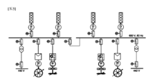
図5は、従来の交流発電装置、正弦波のみを供給する変速の不可能な電力変換装置、極数変換(高速、中速)誘導電動機、単一入力-単一出力減速機、可変ピッチプロペラ型バウスラスタ、可変ピッチプロペラ型スターンスラスタと可変ピッチプロペラで推進する2軸船の電気推進システムを示したものであって、船舶の推進速度が低い場合、図4の電気推進システムから発生される効率低下による運営損失部分の中で、図2に示された誘導電動機の低い回転速度での効率及び力率低下部分は、誘導電動機の回転速度を定格回転速度に維持し、推進用可変ピッチプロペラのピッチ角を低めることによって相殺できるが、このために、高価の装備である可変ピッチプロペラを使用しなければならない。 Figure 5 shows a conventional AC generator, a non-variable power converter that supplies only sine waves, a pole-change (high speed, medium speed) induction motor, a single input-single output speed reducer, and a variable pitch propeller. Figure 4 shows an electric propulsion system for a two-shaft ship propelled by a type bow thruster, a variable pitch propeller type stern thruster, and a variable pitch propeller. Among the operation losses due to the reduction, the efficiency and power factor reduction at low rotational speed of the induction motor shown in Figure 2 is due to the reduction in efficiency and power factor of the induction motor at the rated rotational speed and the variable pitch propeller for propulsion. This can be offset by lowering the pitch angle, but this requires the use of variable pitch propellers, which are expensive equipment.
図6は、従来の交流発電装置、可変速電力変換装置、同期電動機、二重入力-単一出力減速機、固定ピッチプロペラ型バウスラスタ、またはスターンスラスタと固定ピッチプロペラで推進する短軸船の電気推進システムを示したものであって、船舶の推進速度が低い場合、図4の電気推進システムから発生される効率低下による運営損失が発生しうる。これに加えて、二重入力-単一出力減速機に連結された2台の同期電動機の場合、船舶の推進速度によって低速区間で1台の同期電動機が運転され、高速区間で2台の同期電動機が運転される運営方式でなく、船舶の推進速度に関係なく、2台の同期電動機が同時に並列運転をしなければならないので、船舶の推進速度が低い場合、同期電動機の損失は、1台を使用するときに対比して2倍に増加する。 Figure 6 shows the electricity of a short shaft ship propelled by a conventional alternating current generator, variable speed power converter, synchronous motor, dual input-single output reducer, fixed pitch propeller type bow thruster, or stern thruster and fixed pitch propeller. 4 shows a propulsion system, and when the propulsion speed of the ship is low, operational losses may occur due to efficiency reduction generated from the electric propulsion system of FIG. 4. In addition to this, in the case of two synchronous motors coupled to a dual input-single output gearbox, depending on the vessel's propulsion speed, one synchronous motor is operated in the low speed section and two synchronous motors are operated in the high speed section. Regardless of the operation method in which electric motors are operated, two synchronous motors must operate in parallel at the same time regardless of the ship's propulsion speed, so when the ship's propulsion speed is low, the loss of one synchronous motor is It increases twice compared to when using .
図7は、従来の周波数可変交流発電装置、直流配電システム(整流器、インバータ、及びバッテリを含む)、誘導電動機、固定ピッチプロペラ型バウスラスタ、固定ピッチプロペラ型スターンスラスタと固定ピッチプロペラ型全方位推進機で推進する電気推進システムを示したものであって、船舶の推進速度が低い場合、図4の電気推進システムから発生されていた効率低下による運営損失部分は、周波数可変交流発電装置に整流器、インバータ、及びバッテリを追加設置して、従来の交流発電装置に対比して内燃機関の燃料消費量を減少させることにより相殺できるが、このために、高価のこれらの装置を追加的に使用しなければならない。 Figure 7 shows a conventional variable frequency AC generator, DC power distribution system (including rectifier, inverter, and battery), induction motor, fixed pitch propeller type bow thruster, fixed pitch propeller type stern thruster, and fixed pitch propeller type omnidirectional propulsion machine. This figure shows an electric propulsion system that is propelled by a variable frequency alternating current generator, and when the propulsion speed of the ship is low, the operation loss due to the decrease in efficiency generated by the electric propulsion system in , and batteries can be offset by reducing the fuel consumption of the internal combustion engine compared to conventional alternating current generators, but this does not require the additional use of these expensive devices. No.
図8は、従来の50Hzの電力を周波数変換装置を介して60Hzの電力に変換することを示したものであって、電力変換が必要な容量が増加するほど周波数変換装置の値段が増加する。 FIG. 8 shows the conversion of conventional 50 Hz power to 60 Hz power via a frequency converter, and the price of the frequency converter increases as the capacity required for power conversion increases.
図9~図17は、駆動体で出力側回転方向調整が可能なクラッチと歯車が内蔵された装置または出力側回転方向調整が不可能なクラッチと歯車が内蔵された装置を駆動する実施形態を示したものである。 FIGS. 9 to 17 show an embodiment in which a drive body drives a device with a built-in clutch and gears that can adjust the rotation direction on the output side, or a device with a built-in clutch and gears that cannot adjust the rotation direction on the output side. This is what is shown.
例え、詳細に図示されてはいないが、図13~図16に示すように、制御部10a、10bには、無線通信用アンテナ11a、11b、正/逆回転運転信号、オーバーライド制御信号、制御モード信号、回転速度設定値信号、クラッチと歯車が内蔵された装置の入力軸速度感知センサ320a、320b、クラッチと歯車が内蔵された装置の潤滑油温度感知センサ405a、405b、クラッチと歯車が内蔵された装置の潤滑油圧力感知センサ406a、406b、クラッチと歯車が内蔵された装置の出力軸速度感知センサ420a、420b、二重入力-単一出力歯車装置の潤滑油温度感知センサ505a、505b、二重入力-単一出力歯車装置の潤滑油圧力感知センサ506a、506b、二重入力-単一出力歯車装置の出力軸速度感知センサ520a、520bが連結され得る。
For example, although not shown in detail, as shown in FIGS. 13 to 16, the
また、図9~図16に示すように、駆動体と被駆動体の回転速度が異なる場合、クラッチと歯車が内蔵された装置の歯車が前記回転速度の差によるギヤ比を有するようにするか、前記回転速度の差によるギヤ比を有する歯車装置を、クラッチと歯車が内蔵された装置の前端や後端に別に構成することもできる。 Furthermore, as shown in FIGS. 9 to 16, when the rotational speeds of the driving body and the driven body are different, the gears of the device in which the clutch and the gears are built have a gear ratio based on the difference in the rotational speeds. It is also possible to separately configure a gear device having a gear ratio based on the difference in rotational speed at the front end or the rear end of the device in which the clutch and the gear are built.
本発明に係るクラッチを用いた推進及び制動システムの動作及び運営方法について添付された図面を参照して詳細に説明するに先立って、制御部10a、10bで有する特徴を先に説明する。
Before explaining in detail the operation and management method of the propulsion and braking system using a clutch according to the present invention with reference to the attached drawings, the features of the
クラッチと歯車が内蔵された装置400a、400bのクラッチが接続された状態で被駆動体を駆動用誘導電動機300a、300bにて駆動して推進する場合、駆動用誘導電動機スタータ50a、50bから供給される電力の周波数が増加されれば、被駆動体の回転速度が上昇して駆動用誘導電動機300a、300bの負荷が増加されるが、このとき、制御部10a、10bは、駆動用誘導電動機スタータ50a、50bに設けられた電力測定及び監視装置(power metering and monitoring devices、PMD)を介して取得された情報を基準に駆動用誘導電動機300a、300b、クラッチと歯車が内蔵された装置400a、400b、二重入力-単一出力歯車装置(gear unit)500、及びFPPプロペラのような被駆動体600の過負荷運転可能範囲と現在出力量とを比較して、これを超過する場合、運営者に警報し、過負荷運転可能範囲内で運転させる機能がある。
When a driven body is driven and propelled by the driving
また、クラッチと歯車が内蔵された装置400a、400bのクラッチが接続された状態で被駆動体を内燃機関700a、700b、800a、800bにて駆動して推進する場合、内燃機関700a、700b、800a、800bの回転速度が増加すれば、被駆動体の回転速度が上昇して内燃機関700a、700b、800a、800bの負荷が増加するが、このとき、制御部10a、10bは、内燃機関制御装置を介して取得された情報を基準に内燃機関700a、700b、800a、800b、クラッチと歯車が内蔵された装置400a、400b、二重入力-単一出力歯車装置500、及びFPPプロペラのような被駆動体600の過負荷運転可能範囲と現在出力量とを比較して、これを超過する場合、運営者に警報し、過負荷運転可能範囲内で運転させる機能がある。
Further, when the driven body is driven and propelled by the
また、制御部10a、10bは、クラッチと歯車が内蔵された装置400a、400bのクラッチが接続された状態またはクラッチと歯車が内蔵された装置400a、400bのクラッチをクラッチ動作圧力調節用弁で調節して動力を伝達する状態であるとき、駆動用誘導電動機300a、300b、内燃機関700a、700b、800a、800bの回転速度別の出力量と被駆動体600の回転速度別の負荷量とを比較する。被駆動体600の回転速度別の負荷量に対比して駆動用誘導電動機300a、300b、内燃機関700a、700b、800a、800bの回転速度別の出力量が増加した場合、制御部10a、10bは、被駆動体600の回転速度別の負荷量が増加されたことを運営者に警報し、被駆動体600の回転速度別の負荷量に対比して駆動用誘導電動機300a、300b、内燃機関700a、700b、800a、800bの回転速度別の出力量が減少した場合、制御部10a、10bは、被駆動体600の回転速度別の負荷量が減少されたことを運営者に警報する。このとき、駆動体の回転速度別の出力量は、駆動体が駆動用誘導電動機300a、300bである場合には、駆動用誘導電動機スタータ50a、50bに設けられた電力測定及び監視装置を介して取得された情報を基準とし、駆動体が内燃機関700a、700b、800a、800bである場合には、内燃機関制御装置を介して取得された情報を基準に被駆動体600の負荷量増加及び減少可否を判断する。被駆動体600に異物が付着されて抵抗が増加すれば、負荷量が増加し、被駆動体600に摩耗が発生されて抵抗が減少されれば、負荷量が減少する。
In addition, the
また、クラッチと歯車が内蔵された装置400a、400bの潤滑油圧力は、装置の潤滑油温度が高いほど低くなる傾向がある。したがって、制御部10a、10bは、潤滑油温度感知センサ405a、405b及び潤滑油圧力感知センサ406a、406bを用いて装置の潤滑油温度及び圧力を測定した後、測定値等の変化量を学習して潤滑油粘度(viscosity)の安定性を確認する機能がある。
Furthermore, the lubricating oil pressure of the
また、クラッチと歯車が内蔵された装置400a、400bのクラッチが接続された状態で、前記装置の入力軸310a、310bに設けられた入力軸速度感知センサ320a、320bで測定した回転速度と前記装置の出力軸410a、410bに設けられた出力軸速度感知センサ420a、420bで測定した回転速度とに差がある場合、制御部10a、10bは、このような差の大きさでクラッチ摩耗度(clutch wear degree)を判断できる。
In addition, when the clutches of the
また、クラッチと歯車が内蔵された装置400a、400bのクラッチが接続されなかった状態で被駆動体600の回転速度を一定に維持するために、制御部10a、10bでクラッチ動作圧力調節用弁に伝達する設定値(set point)は、潤滑油圧力が変わると異なるようになるが、このような設定値の変化量が潤滑油温度変化による変動値を超過する場合、このような差の大きさでもクラッチ摩耗度を判断する機能がある。
In addition, in order to maintain the rotational speed of the driven
また、制御部10a、10bは、クラッチのスリップ発生の際、被駆動体の回転速度があまり遅いか、被駆動体の回転速度が駆動体の回転速度に近接した状況でスティックスリップ(stick slip)現象が発生することをクラッチと歯車が内蔵された装置の入力軸310a、310bに設けられた入力軸速度感知センサ320a、320bと前記装置の出力軸410a、410bに設けられた出力軸速度感知センサ420a、420bとで測定した回転速度に対する角速度分析にて検出し、これをクラッチの動作に必要な油圧調整修正係数(correction factor)として使用してクラッチ動作油圧決定回路または回転速度決定回路に反映し、これを介してクラッチ動作圧力調節用弁の設定値を増感させてスティックスリップを回避する機能がある。
Furthermore, when clutch slip occurs, the
また、制御部10a、10bは、駆動体が駆動用誘導電動機300a、300bであるとき、速度制御モードである場合には、被駆動体の回転速度を一定に維持させる制御を行い、負荷制御モードである場合には、駆動用誘導電動機スタータ50a、50bに設けられた電力測定及び監視装置を介して取得された情報を基準に駆動用誘導電動機300a、300bにかかる負荷を一定に維持させる制御を行う機能がある。
Further, when the driving body is the driving
また、駆動体が内燃機関700a、700b、800a、800bであるとき、速度制御モードである場合には、被駆動体の回転速度を一定に維持させる制御を行い、負荷制御モードである場合には、内燃機関制御装置を介して取得された情報を基準に内燃機関700a、700b、800a、800bにかかる負荷を一定に維持させる制御を行う機能がある。
Further, when the driving body is an
また、クラッチと歯車が内蔵された装置400a、400bのクラッチが接続されず、オーバーライド制御機能が活性化されている状態で、前記装置の潤滑油冷却装置などの故障のため、潤滑油温度感知センサ405a、405bで測定した前記装置400a、400bの潤滑油温度が許容値以上に上昇すれば、制御部10a、10bは、前記装置400a、400bの制御を回転速度制御から潤滑油温度一定制御に転換し、クラッチと歯車が内蔵された装置400a、400bの潤滑油温度が警報値のヒステリシス(Hysteresis)以内に減少すれば、回転速度制御に再度復帰する機能がある。
In addition, when the clutches of the
また、駆動体が駆動用誘導電動機300a、300bである場合、被駆動体の過渡(transient)負荷急上昇が発生すれば、電力を供給する内燃機関の回転速度が落ち、駆動用誘導電動機スタータ50a、50bから駆動用誘導電動機300a、300bに供給される周波数が低くなる。このとき、電力急上昇量(Δp/Δt)は、前記装置の入力軸310a、310bに設けられた入力軸速度感知センサ320a、320bで測定した回転速度変化量(Δrpm/Δt)、または駆動用誘導電動機スタータ50a、50bに設けられた電力測定及び監視装置を介して取得された時間当り周波数変化量(Δfrequency/Δt)、または駆動用誘導電動機スタータ50a、50bに設けられた電力測定及び監視装置を介して取得された時間当り有効電力変化量(Δkw/Δt)として検出されることができる。制御部10a、10bは、上述した被駆動体の過渡負荷急上昇を検出し、過渡負荷急上昇の大きさによって電力を供給する内燃機関の周波数過渡特性に対する性能等級作動限界値で許容する周波数回復時間(frequency recovery time after load increase)以内に周波数が回復されるようにすることができる。すなわち、制御部10a、10bは、クラッチ動作圧力調節用弁の設定値を調節し、電力急上昇量によって予め設定された被駆動体の負荷減少量に合うようにスリップを増加させて内燃機関の負荷を低めることにより、電力供給内燃機関の回転速度が早速回復されるようにした後、回転速度の回復が感知されれば、クラッチ動作圧力調節用弁の設定値を再度元の設定値に徐々に復帰させる機能がある。
Further, when the driving bodies are the driving
また、駆動体が内燃機関700a、700b、800a、800bである場合、被駆動体の過渡負荷急上昇が発生すれば、駆動力を供給する内燃機関700a、700b、800a、800bの回転速度が落ちる。このとき、駆動力急上昇量(Δp/Δt)は、前記装置の入力軸310a、310bに設けられた入力軸速度感知センサ320a、320bで測定した回転速度変化量(Δrpm/Δt)として検出されることができる。制御部10a、10bは、上述した被駆動体の過渡負荷急上昇を検出し、過渡負荷急上昇の大きさによって駆動力を供給する内燃機関700a、700b、800a、800bの回転速度過渡特性に対する性能等級作動限界値で許容する回転速度回復時間以内に駆動体の回転速度が回復されるようにすることができる。すなわち、制御部10a、10bは、クラッチ動作圧力調節用弁の設定値を調節し、駆動力急上昇量によって予め設定された被駆動体の負荷減少量に合うようにスリップを増加させて前記内燃機関700a、700b、800a、800bの負荷を低めることにより、前記内燃機関700a、700b、800a、800bの回転速度が早速回復されるようにした後、回転速度の回復が感知されれば、クラッチ動作圧力調節用弁の設定値を再度元の設定値に徐々に復帰させる機能がある。
Furthermore, when the driving bodies are
また、クラッチと歯車が内蔵された装置400aの出力軸410aまたは二重入力-単一出力歯車装置の出力軸510に摩擦ブレーキ550が設けられる場合、制動制御の際、摩擦ブレーキ550は、前記装置400aのクラッチと連動制御されることができる。すなわち、制御部10a、10bは、制動信号が入力されて前記装置400aのクラッチが遮断(disengagement)されれば、摩擦ブレーキ550を動作させ、被駆動体600の逆回転用意が完了して、前記装置400aのクラッチ動作圧力調節が進行されれば、摩擦ブレーキ550の動作を解除させ、推進体が停止すれば、摩擦ブレーキ550を再度動作させる機能がある。
Further, when a
また、制御部10a、10bは、入力される回転速度設定値の変化勾配でクラッチ動作圧力調節用弁の動作時間を調整して推進及び制動にかかる時間を調整できる機能がある。
Further, the
以下、本発明に係るクラッチを用いた推進及び制動システムの動作及び運営方法について添付された図面を参照して詳細に説明する。 Hereinafter, the operation and operation method of the propulsion and braking system using a clutch according to the present invention will be described in detail with reference to the accompanying drawings.
図9、図10、図13、図14、図17に示されたクラッチと歯車が内蔵された装置400a、400bは、推進体の正回転運転の際、入力軸/出力軸の同一回転方向制御用クラッチ401a、401bが動作し、逆回転運転の際、入力軸/出力軸の反対回転方向制御用クラッチ402a、402bが動作することを前提として説明する。
図9は、本発明に係る被駆動体回転方向を駆動体と同じ方向または反対方向に調整が可能なクラッチと歯車が内蔵された装置400aを駆動用誘導電動機300aにて駆動する実施形態を示したものであって、駆動体として使用される駆動用誘導電動機300aの起動の際に発生される起動電流を制限するための方法として、小型誘導電動機をフォニー電動機(200a、pony motor)として使用する。駆動用誘導電動機300a軸にフォニー電動機出力軸210aを連結した後、フォニー電動機スタータ100aで電力供給用ケーブルfを介してフォニー電動機200aに全電圧(full voltage)を印加すれば、駆動用誘導電動機300aの回転子をフォニー電動機200aの定格回転速度まで回転させることができる。このとき、フォニー電動機200aの起動電流も制限する必要がある場合には、フォニー電動機スタータ100aに減電圧(reduced voltage)起動(Y-Δ起動または1次抵抗起動またはリアクター起動または単巻変圧器起動またはソフトスタータ(soft starter)起動)のための装置を備える。
FIG. 9 shows an embodiment in which a
制御部10aは、フォニー電動機200aを起動させた後、起動完了可否を前記装置の入力軸310aに設けられた入力軸速度感知センサ320aの回転速度で判断する。このとき、駆動用誘導電動機300aの回転子が定格回転速度に到達すれば、制御部10aは、フォニー電動機スタータ100aに電力遮断信号を伝達し、駆動用誘導電動機スタータ50aに電力供給信号を伝達する。その後、電力供給用ケーブルcを介して駆動用誘導電動機300aに電力が供給されれば、起動電流を制限した駆動用誘導電動機300aの起動が完了する。
After starting the phonie
駆動用誘導電動機300aの起動が完了すれば、制御部10aは、正回転運転の場合、前記装置400aの同一回転方向制御用クラッチ401aの弁を開放した後、回転速度設定値が維持され得るようにクラッチ動作圧力調節用弁を調節して、同一回転方向制御用クラッチ401aの動作圧力を制御する。このとき、制御部10aは、前記装置の出力軸410aに設けられた出力軸速度感知センサ420aを介して被駆動体600の回転速度を確認できる。
Once the driving
被駆動体600の回転速度設定値が、駆動用誘導電動機300aが定格回転速度であるとき、出力軸速度感知センサ420aで確認される回転速度以上であるか、予め設定されたクラッチのスリップを利用した回転速度以上である場合、制御部10aは、予め設定された動作速度によってクラッチ動作圧力調節用弁を完全に開放して、同一回転方向制御用クラッチ401aを接続させるか、クラッチ動作圧力調節用弁の機能を一時に除去し、クラッチ動作潤滑油の圧力が全て同一回転方向制御用クラッチ401aに伝達されるようにして、同一回転方向制御用クラッチ401aを接続させる。このように、クラッチ動作圧力調節用弁の機能を一時に除去する場合、被駆動体600の回転速度が瞬間的に落ちる現象が発生しうる。
When the rotational speed setting value of the driven
被駆動体600の推進中に制動をするために、制御部10aに回転速度設定値として逆回転信号を入力すれば、同一回転方向制御用クラッチ401a弁を遮断して同一回転方向制御用クラッチ401aを遮断し、クラッチ動作圧力調節用弁の動作圧力を除去する。また、被駆動体600の回転方向を反対方向に制御するために、反対回転方向制御用クラッチ402a弁を開放した後、クラッチ動作圧力調節用弁で動作圧力を調節して推進体の制動のための逆回転制御を行う。その後、推進体が停止されて回転速度設定値が「0」rpmに入力されれば、反対回転方向制御用クラッチ402a弁を遮断する。
In order to brake the driven
クラッチの摩擦で発生される熱により前記装置400aの潤滑油温度が上昇するが、制御部10aは、前記装置の潤滑油温度感知センサ405aで測定した潤滑油温度が警報値未満に維持されるようにクラッチ動作圧力調節用弁の動作圧力を制御できる。
Although the lubricating oil temperature in the
図10は、本発明に係る出力側回転方向調整が可能なクラッチと歯車が内蔵された装置400aを4行程内燃機関700aにて駆動する実施形態を示したものである。駆動体として使用される4行程内燃機関700aの始動が完了すれば、制御部10aは、正回転運転の場合、前記装置400aの同一回転方向制御用クラッチ401a弁を開放した後、回転速度設定値が維持され得るようにクラッチ動作圧力調節用弁を調節して、同一回転方向制御用クラッチ401aの動作圧力を制御する。このとき、制御部10aは、前記装置の出力軸410aに設けられた出力軸速度感知センサ420aを介して被駆動体600の回転速度を確認できる。
FIG. 10 shows an embodiment in which a
被駆動体600の回転速度設定値が、4行程内燃機関700aが定格回転速度であるとき、出力軸速度感知センサ420aで確認される回転速度以上であるか、予め設定されたクラッチのスリップを利用した回転速度以上である場合、制御部10aは、予め設定された動作速度によってクラッチ動作圧力調節用弁を完全に開放して、同一回転方向制御用クラッチ401aを接続させるか、クラッチ動作圧力調節用弁の機能を一時に除去し、クラッチ動作潤滑油の圧力が全て同一回転方向制御用クラッチ401aに伝達されるようにして、同一回転方向制御用クラッチ401aを接続させる。このように、クラッチ動作圧力調節用弁の機能を一時に除去する場合、被駆動体600の回転速度が瞬間的に落ちる現象が発生しうる。
When the rotational speed setting value of the driven
被駆動体600の推進中に制動をするために、制御部10aに回転速度設定値として逆回転信号を入力すれば、同一回転方向制御用クラッチ401a弁を遮断して同一回転方向制御用クラッチ401aを遮断し、クラッチ動作圧力調節用弁の動作圧力を除去する。また、被駆動体600の回転方向を反対方向に制御するために、反対回転方向制御用クラッチ402a弁を開放した後、クラッチ動作圧力調節用弁で動作圧力を調節して推進体の制動のための逆回転制御を行う。その後、推進体が停止されて回転速度設定値が「0」rpmに入力されれば、反対回転方向制御用クラッチ402a弁を遮断する。
In order to brake the driven
クラッチの摩擦で発生される熱により前記装置400aの潤滑油温度が上昇するが、制御部10aは、前記装置の潤滑油温度感知センサ405aで測定した潤滑油温度が警報値未満に維持されるようにクラッチ動作圧力調節用弁の動作圧力を制御できる。
Although the lubricating oil temperature in the
図11は、本発明に係る出力側回転方向調整が不可能なクラッチと歯車が内蔵された装置400aを駆動用誘導電動機300aにて駆動する実施形態を示したものである。
FIG. 11 shows an embodiment in which a
駆動体として使用される駆動用誘導電動機300aの起動の際に発生される起動電流を制限するための方法として、小型誘導電動機をフォニー電動機200aとして使用する。具体的に、駆動用誘導電動機300a軸にフォニー電動機出力軸210aを連結した後、フォニー電動機スタータ100aに設けられたソフトスタータで電力供給用ケーブルfを介してフォニー電動機200aを減電圧起動し、駆動用誘導電動機300aの回転子をフォニー電動機200aの定格回転速度まで回転させる。このとき、フォニー電動機200aの起動電流を制限する必要がなく、停止の際の惰力運転(coasting operation)時間が短い場合には、フォニー電動機スタータ100aに全電圧起動のための装置を備える。
As a method for limiting the starting current generated when starting the
制御部10aは、フォニー電動機200aを起動させた後、起動完了可否を前記装置の入力軸310aに設けられた入力軸速度感知センサ320aの回転速度で判断する。このとき、駆動用誘導電動機300aの回転子が定格回転速度に到達すれば、制御部10aは、フォニー電動機スタータ100aに電力遮断信号を伝達し、駆動用誘導電動機スタータ50aに電力供給信号を伝達する。その後、電力供給用ケーブルcを介して駆動用誘導電動機300aに電力が供給されれば、起動電流を制限した駆動用誘導電動機300aの起動が完了する。
After starting the phonie
駆動用誘導電動機300aの起動が完了すれば、制御部10aは、正回転運転の場合、前記装置400aの同一回転方向制御用クラッチ401a弁を開放した後、回転速度設定値が維持され得るようにクラッチ動作圧力調節用弁を調節して、同一回転方向制御用クラッチ401aの動作圧力を制御する。このとき、制御部10aは、前記装置の出力軸410aに設けられた出力軸速度感知センサ420aを介して被駆動体600の回転速度を確認できる。
When the driving
被駆動体600の回転速度設定値が、駆動用誘導電動機300aが定格回転速度であるとき、出力軸速度感知センサ420aで確認される回転速度以上であるか、予め設定されたクラッチのスリップを利用した回転速度以上である場合、制御部10aは、予め設定された動作速度によってクラッチ動作圧力調節用弁を完全に開放し、同一回転方向制御用クラッチ401aを接続させるか、クラッチ動作圧力調節用弁の機能を一時に除去し、クラッチ動作潤滑油の圧力が全て同一回転方向制御用クラッチ401aに伝達されるようにして、同一回転方向制御用クラッチ401aを接続させる。このように、クラッチ動作圧力調節用弁の機能を一時に除去する場合、被駆動体600の回転速度が瞬間的に落ちる現象が発生しうる。
When the rotational speed setting value of the driven
被駆動体600の推進中に制動をするために、制御部10aに回転速度設定値として逆回転信号を入力すれば、同一回転方向制御用クラッチ401a弁を遮断して同一回転方向制御用クラッチ401aを遮断し、クラッチ動作圧力調節用弁の動作圧力を除去する。また、駆動用誘導電動機スタータ50aの電源を遮断した後、フォニー電動機スタータ100aに設けられたソフトスタータを動作させてソフトスタータのブレーキ機能を利用することで、フォニー電動機200aを停止させる。
In order to brake the driven
その後、フォニー電動機200aの停止可否が前記装置の入力軸310aに設けられた入力軸速度感知センサ320aの回転速度で確認されれば、フォニー電動機200aの逆回転のために、ソフトスタータに供給される電源の上回転方向を逆方向に転換した後、フォニー電動機スタータ100aに設けられたソフトスタータで電力供給用ケーブルfを介してフォニー電動機200aを減電圧起動し、駆動用誘導電動機300aの回転子をフォニー電動機200aの定格回転速度まで逆回転させる。
After that, if it is confirmed whether or not the
制御部10aは、フォニー電動機200aの逆回転起動を完了した後、起動完了可否を前記装置の入力軸310aに設けられた入力軸速度感知センサ320aの回転速度で判断する。このとき、駆動用誘導電動機300aの回転子が定格回転速度に到達すれば、制御部10aは、フォニー電動機スタータ100aに電力遮断信号を伝達し、駆動用誘導電動機スタータ50aに電源の上回転方向が逆方向に転換された電力供給信号を伝達する。その後、電力供給用ケーブルcを介して駆動用誘導電動機300aに電力が供給されれば、起動電流を制限した駆動用誘導電動機300aの逆回転起動が完了する。
After the
駆動用誘導電動機300aの逆回転が前記装置の入力軸310aに設けられた入力軸速度感知センサ320aの回転速度で判断されれば、被駆動体600の回転方向を反対方向に制御するために、同一回転方向制御用クラッチ401a弁を開放した後、クラッチ動作圧力調節用弁で動作圧力を調節して推進体の制動のための逆回転制御を行う。その後、推進体が停止されて回転速度設定値が「0」rpmに入力されれば、反対回転方向制御用クラッチ401a弁を遮断する。
If the reverse rotation of the driving
クラッチの摩擦で発生される熱によりクラッチと歯車が内蔵された装置400aの潤滑油温度が上昇するが、制御部10aは、前記装置の潤滑油温度感知センサ405aで測定した潤滑油温度が警報値未満に維持されるようにクラッチ動作圧力調節用弁の動作圧力を制御できる。
The lubricating oil temperature of the
図12は、本発明に係る出力側回転方向調整が不可能なクラッチと歯車が内蔵された装置400aを2行程内燃機関800aにて駆動する実施形態を示したものである。
FIG. 12 shows an embodiment in which a two-stroke
駆動体として使用される2行程内燃機関800aの始動が完了すれば、制御部10aは、正回転運転の場合、前記装置400aの同一回転方向制御用クラッチ401a弁を開放した後、回転速度設定値が維持され得るようにクラッチ動作圧力調節用弁を調節して、同一回転方向制御用クラッチ401aの動作圧力を制御する。このとき、制御部10aは、前記装置の出力軸410aに設けられた出力軸速度感知センサ420aを介して被駆動体600の回転速度を確認できる。
When the starting of the two-stroke
被駆動体600の回転速度設定値が、2行程内燃機関800aが定格回転速度であるとき、出力軸速度感知センサ420aで確認される回転速度以上であるか、予め設定されたクラッチのスリップを利用した回転速度以上である場合、制御部10aは、予め設定された動作速度によってクラッチ動作圧力調節用弁を完全に開放して、同一回転方向制御用クラッチ401aを接続させるか、クラッチ動作圧力調節用弁の機能を一時に除去し、クラッチ動作潤滑油の圧力が全て同一回転方向制御用クラッチ401aに伝達されるようにして、同一回転方向制御用クラッチ401aを接続させる。このように、クラッチ動作圧力調節用弁の機能を一時に除去する場合、被駆動体600の回転速度が瞬間的に落ちる現象が発生しうる。
When the rotational speed setting value of the driven
被駆動体600の推進中に制動をするために、制御部10aに回転速度設定値として逆回転信号を入力すれば、同一回転方向制御用クラッチ401a弁を遮断して同一回転方向制御用クラッチ401aを遮断し、クラッチ動作圧力調節用弁の動作圧力を除去する。2行程内燃機関800aを停止させた後、2行程内燃機関800aの停止可否が前記装置の入力軸310aに設けられた入力軸速度感知センサ320aの回転速度で確認されれば、2行程内燃機関800aを逆回転で始動して定格回転速度まで回転させる。2行程内燃機関800aの逆回転が前記装置の入力軸310aに設けられた入力軸速度感知センサ320aの回転速度で判断されれば、被駆動体600の回転方向を反対方向に制御するために、同一回転方向制御用クラッチ401a弁を開放した後、クラッチ動作圧力調節用弁で動作圧力を調節して推進体の制動のための逆回転制御を行う。その後、推進体が停止されて回転速度設定値が「0」rpmに入力されれば、反対回転方向制御用クラッチ401a弁を遮断する。
In order to brake the driven
クラッチの摩擦で発生される熱により前記装置400aの潤滑油温度が上昇するが、制御部10aは、潤滑油温度感知センサ405aで測定した潤滑油温度が警報値未満に維持されるようにクラッチ動作圧力調節用弁の動作圧力を制御できる。
Although the lubricating oil temperature in the
図13は、本発明に係る出力側回転方向調整が可能なクラッチと歯車が内蔵された装置400a、400bを駆動用誘導電動機300a、300bにて駆動して二重入力-単一出力歯車装置500で並列運転する実施形態を示したものであり、図14は、本発明に係る出力側回転方向調整が可能なクラッチと歯車が内蔵された装置400a、400bを4行程内燃機関700a、700bにて駆動して二重入力-単一出力歯車装置500で並列運転する実施形態を示したものであり、図15は、本発明に係る出力側回転方向調整が不可能なクラッチと歯車が内蔵された装置400a、400bを駆動用誘導電動機300a、300bにて駆動して二重入力-単一出力歯車装置500で並列運転する実施形態を示したものであり、図16は、本発明に係る出力側回転方向調整が不可能なクラッチと歯車が内蔵された装置400a、400bを2行程内燃機関800a、800bにて駆動して二重入力-単一出力歯車装置500で並列運転する実施形態を示したものである。
FIG. 13 shows a dual input-single
このように、二重入力-単一出力歯車装置500を使用する場合、被駆動体600の回転速度設定値が低ければ、1台の駆動体で被駆動体600を運転し、回転速度設定値が高ければ、2台の駆動体で被駆動体600を運転する順次的負荷運転及び並列運転を同期化過程なしに行うことができる。
In this way, when using the dual input-single
以下、図13~図14に示された出力側回転方向調整が可能なクラッチと歯車が内蔵された装置400a、400bが駆動体300aと300b、700aと700bに連結されて、二重入力-単一出力歯車装置500で順次的負荷運転及び並列運転を行う方法について説明する。
Hereinafter,
駆動体の負荷運転順序は、左側の駆動用誘導電動機300a、4行程内燃機関700aが先に運転され、右側の駆動用誘導電動機300b、4行程内燃機関700bが後で運転されることと仮定して説明する。
It is assumed that the load operation order of the driving bodies is that the left-hand
駆動体300a、700aの始動が完了すれば、制御部10aは、正回転運転の場合、前記装置400aの同一回転方向制御用クラッチ401a弁を開放した後、回転速度設定値が維持され得るようにクラッチ動作圧力調節用弁を調節して、同一回転方向制御用クラッチ401aの動作圧力を制御する。このとき、制御部10aは、二重入力-単一出力歯車装置の出力軸510に設けられた出力軸速度感知センサ520aを介して被駆動体600の回転速度を確認できる。
When the starting of the driving
被駆動体600の回転速度設定値が既運転中の左側駆動体300a、700aの回転速度別の出力以上であるか、予め設定されたクラッチのスリップを利用した左側駆動体300a、700aの回転速度別の出力以上である場合、制御部10bは、右側駆動体300b、700bを始動し、前記装置400bの同一回転方向制御用クラッチ401a弁を開放した後、回転速度設定値が維持され得るようにクラッチ動作圧力調節用弁を調節して、同一回転方向制御用クラッチ401aの動作圧力を制御する。このとき、制御部10bは、二重入力-単一出力歯車装置の出力軸510に設けられた出力軸速度感知センサ520aを介して被駆動体600の回転速度を確認できる。
Whether the set value of the rotational speed of the driven
制御部10a、10bは、前記装置400a、400bの同一回転方向制御用クラッチ401aの動作圧力を制御しながら並列運転を行うが、被駆動体600の回転速度設定値が、2台の駆動体300aと300b、700aと700bが定格回転速度で出すことのできる定格出力以上であるか、予め設定されたクラッチのスリップを利用した2台の駆動体300aと300b、700aと700bの回転速度別の出力以上である場合、制御部10a、10bは、予め設定された動作速度によってクラッチ動作圧力調節用弁を完全に開放して、同一回転方向制御用クラッチ401aを接続させるか、クラッチ動作圧力調節用弁の機能を一時に除去し、前記装置400a、400bで形成されたクラッチ動作潤滑油の圧力が全て同一回転方向制御用クラッチ401aに伝達されるようにして、同一回転方向制御用クラッチ401aを接続させる。このように、クラッチ動作圧力調節用弁の機能を一時に除去する場合、被駆動体600の回転速度が瞬間的に落ちる現象が発生しうる。
The
2台のクラッチと歯車が内蔵された装置400a、400bのクラッチが接続された状態で駆動体300aと300b、700aと700bの回転速度設定値が互いに同じであれば、駆動体間の均等負荷運転(symmetric load sharing)がなされ、異なると、不均等負荷運転(asymmetric load sharing)がなされる。
If the rotational speed settings of the driving
被駆動体600の推進中に制動をするために、制御部10a、10bに回転速度設定値として逆回転信号を入力すれば、同一回転方向制御用クラッチ401a弁を遮断して同一回転方向制御用クラッチ401aを遮断し、クラッチ動作圧力調節用弁の動作圧力を除去する。
In order to brake the driven
また、被駆動体600の回転方向を反対方向に制御するために、反対回転方向制御用クラッチ402aを動作させた後、クラッチ動作圧力調節用弁で動作圧力を増加させて推進体の制動のための逆回転制御を行う。その後、推進体が停止されて回転速度設定値が「0」rpmに入力されれば、反対回転方向制御用クラッチ402a弁を遮断する。
Further, in order to control the rotational direction of the driven
クラッチの摩擦で発生する熱により前記装置400a、400bの潤滑油温度が上昇するが、制御部10a、10bでは、前記装置の潤滑油温度感知センサ405a、405bで測定した潤滑油温度が警報値未満に維持されるようにクラッチ動作圧力調節用弁の動作圧力を制御できる。
The lubricating oil temperature in the
図15~図16に示された出力側回転方向調整が不可能なクラッチと歯車が内蔵された装置400a、400bが駆動体300aと300b、800aと800bに連結されて、二重入力-単一出力歯車装置500に順次的負荷運転及び並列運転を行う方法は、図13~図14について説明したように行うことができるが、出力側回転方向調整が不可能なクラッチと歯車が内蔵された装置400a、400bが使用されるので、被駆動体600の推進中に制動をするために、制御部10a、10bに回転速度設定値として逆回転信号を入力すれば、駆動体300aと300b、800aと800bを図11~図12において説明したように、駆動体の回転方向を逆回転させた後、制動制御を行う。
図13~図16について説明したように、本発明に係るクラッチを用いた推進及び制動システムは、既存の推進システムとは異なり、順次的負荷運転及び並列運転のための同期化が必要でないので、前記装置出力軸410a、410bに設けられた出力軸速度感知センサ420a、420bが同期化のために使用されず、大きい出力が要求される被駆動体600を種々の駆動体で駆動する場合、入力数が増加された二重(多重)入力-単一出力歯車装置を使用すれば良い。このとき、二重(多重)入力-単一出力歯車装置500の運転状態は、それぞれの制御部10a、10bに連結された潤滑油温度感知センサ505a、505b、潤滑油圧力感知センサ506a、506bで確認されることができる。また、駆動体間の並列運転の際、負荷分担状態を回転速度では判断できないので、駆動体が駆動用誘導電動機である場合には、駆動用誘導電動機スタータ50a、50bに設けられた電力測定及び監視装置で取得された情報(例、有効電力(kW)等)を基準に負荷量を判断し、駆動体が内燃機関である場合には、内燃機関制御装置を介して取得された情報(例、燃料噴射量またはシリンダーに供給される空気圧力等)を基準に負荷量を判断する。
As explained with reference to FIGS. 13 to 16, unlike existing propulsion systems, the clutch-based propulsion and braking system according to the present invention does not require synchronization for sequential load operation and parallel operation. When the output shaft
運転中の駆動体間の負荷偏差が発生しないように、制御部10a、10bは、並列運転を進行する間、これらの情報を通信にて交換してクラッチ動作圧力調節用弁を調節することにより均等負荷運転(symmetric load sharing)を行うことができ、仮に、制御部10a、10bに不均等負荷運転(asymmetric load sharing)設定がなされている場合には、これを反映してクラッチ動作圧力調節用弁を調節できる。また、二重入力-単一出力歯車装置500に連結された駆動体が互いに異なる場合(駆動用誘導電動機と内燃機関との間の並列運転)にも、前記並列運転が可能であることは当たり前である。
In order to prevent load deviation between the driving bodies during operation, the
二重入力-単一出力減速機を使用する既存の2機1軸船のFPP推進システムは、駆動体間の並列運転状態でのみ運転が可能であるので、駆動体の低速、低負荷運転の際、全体エネルギー運営効率低下が発生し、また、駆動体等が全て正常運転状態であるときのみ、船舶の推進が可能であるが、本発明のクラッチを用いた推進及び制動システムでは、駆動体の順次的負荷運転実施が可能であることにより、全体エネルギー運営効率増大を期待でき、駆動体のうち、1台のみ運転が可能な場合にも、船舶の推進が可能であるので、船舶の運営信頼性を高めることができる。 The existing FPP propulsion system for two-engine, single-shaft vessels that uses a dual input-single output speed reducer can only be operated in parallel operation between the drive bodies, so it is difficult to operate the drive bodies at low speed and under low load. However, in the propulsion and braking system using the clutch of the present invention, the overall energy management efficiency decreases, and the ship can be propelled only when all the drive bodies etc. are in normal operating condition. By being able to carry out sequential load operation, we can expect an increase in the overall energy management efficiency, and even if only one of the drive units can be operated, the ship can be propelled, so the ship operation can be improved. Reliability can be increased.
図17は、本発明に係る出力側回転方向調整が可能なクラッチと歯車が内蔵された装置を駆動用誘導電動機にて駆動して被駆動用誘導電動機で周波数が変換された電力を生産する実施形態を示したものであって、出力側回転方向調整が可能なクラッチと歯車が内蔵された装置を使用する場合、被駆動用誘導電動機70を誘導発電機として使用するとき、上回転方向を反対に転換することができる。
FIG. 17 shows an implementation in which a device incorporating a clutch and gears capable of adjusting the rotational direction on the output side according to the present invention is driven by a driving induction motor, and power whose frequency is converted by a driven induction motor is produced. When using a device with a built-in clutch and gears that can adjust the output side rotation direction, when the driven
6極(pole)駆動用誘導電動機300aに50Hzが供給されれば、スリップに鑑みたとき、回転子の回転速度は、l,000rpm未満で回転するようになる。また、8極(pole)駆動用誘導電動機300aに60Hzが供給されれば、スリップに鑑みるとき、回転子の回転速度は、900rpm未満で回転するようになるが、50Hzが供給されれば、スリップに鑑みるとき、回転子の回転速度は750rpm未満で回転するようになる。したがって、50Hzが供給される6極駆動用誘導電動機300aで8極被駆動用誘導電動機70を900rpmで回転させると、60Hzの電力を得ることができ、60Hzが供給される8極駆動用誘導電動機300aで8極被駆動用誘導電動機70を750rpmで回転させると、50Hzの電力を得ることができる。
If 50 Hz is supplied to the six-pole
以下、60Hzの被駆動用誘導電動機スタータ60の電力を電力供給用ケーブルeを介して被駆動用誘導電動機70に供給し、8極900rpmの被駆動用誘導電動機出力軸71がカップリング72を介してポンプ入力軸73に連結されている稼動中のポンプ80を50Hzの周波数変換装置として使用することを説明する。
Hereinafter, power from the 60 Hz
周波数変換装置として使用するために、被駆動用誘導電動機出力軸71とポンプ80とのカップリング72は分離し、被駆動用誘導電動機出力軸71とクラッチと歯車が内蔵された装置の出力軸410aとは連結し、60Hzの被駆動用誘導電動機スタータ60の代わりに、50Hzの電源遮断器盤3を使用する。
In order to use it as a frequency conversion device, the
駆動体として使用される駆動用誘導電動機300aの起動の際に発生される起動電流を制限するための方法として、小型誘導電動機をフォニー電動機200aとして使用する。駆動用誘導電動機300a軸にフォニー電動機出力軸210aを連結した後、フォニー電動機スタータ100aで電力供給用ケーブルfを介してフォニー電動機200aに全電圧を印加すれば、駆動用誘導電動機300aの回転子をフォニー電動機200aの定格回転速度まで回転させることができる。このとき、フォニー電動機200aの起動電流も制限する必要がある場合には、フォニー電動機スタータ100aに減電圧起動(Y-Δ起動または1次抵抗起動またはリアクター起動または単巻変圧器起動またはソフトスタータ起動)のための装置を備える。
As a method for limiting the starting current generated when starting the
制御部10aでは、フォニー電動機200aを起動させた後、起動完了可否を前記装置の入力軸310aに設けられた入力軸速度感知センサ320aの回転速度で判断する。このとき、駆動用誘導電動機300aの回転子が定格回転速度に到達すれば、制御部10aは、フォニー電動機スタータ100aに電力遮断信号を伝達し、駆動用誘導電動機スタータ50aに電力供給信号を伝達する。その後、電力供給用ケーブルcを介して駆動用誘導電動機300aに電力が供給されれば、起動電流を制限した駆動用誘導電動機300aの起動が完了する。
After starting the
駆動用誘導電動機300aの起動が完了すれば、制御部10aは、正/逆回転運転信号状態によって正回転(normal rotation)運転の場合、前記装置400aの同一回転方向制御用クラッチ401a弁を開放した後、回転速度設定値が維持され得るようにクラッチ動作圧力調節用弁を調節して、同一回転方向制御用クラッチ401aの動作圧力を制御する。このとき、制御部10aは、前記装置の出力軸410aに設けられた出力軸速度感知センサ420aを介して被駆動用誘導電動機70の回転速度を確認できる。
When the driving
被駆動用誘導電動機70の回転速度が回転速度設定値に到達すれば、制御部10aは、50Hzの電源遮断器盤3の遮断器を接続して被駆動用誘導電動機70を50Hz電源と連結した後、クラッチ動作圧力調節用弁の調節を介して同一回転方向制御用クラッチ401aの動作圧力を上昇させる。このとき、回転子の速度を同期速度より速くすれば、被駆動用誘導電動機70は、誘導発電機として動作する。
When the rotational speed of the driven
誘導発電機の出力量は、回転速度設定値を調整して制御すれば良いが、通常、同期速度より3%増加されれば、定格出力が発生される。電力制御システムがある場合、クラッチと歯車が内蔵された装置の出力量を制御部10aの回転速度設定値信号を介して制御することもできる。
The output amount of the induction generator can be controlled by adjusting the rotation speed setting value, but normally, the rated output is generated when the rotation speed is increased by 3% from the synchronous speed. If a power control system is present, the output of the device incorporating the clutch and gears can also be controlled via the rotational speed setpoint signal of the
誘導発電機の上回転方向が反対にならなければならない場合には、駆動用誘導電動機300aの起動が完了した後、制御部10aに逆回転信号を与えると、前記装置400aの反対回転方向制御用クラッチ402a弁を開放した後、回転速度設定値が維持され得るようにクラッチ動作圧力調節用弁を調節して、反対回転方向制御用クラッチ402aの動作圧力を制御する。このとき、制御部10aは、前記装置出力軸410aに設けられた出力軸速度感知センサ420aを介して被駆動用誘導電動機70の回転速度を確認できる。
When the upward rotation direction of the induction generator has to be reversed, when a reverse rotation signal is given to the
被駆動用誘導電動機70の回転速度が回転速度設定値に到達すれば、制御部10aは、50Hzの電源遮断器盤3の遮断器を接続して被駆動用誘導電動機70を50Hzの電源と連結した後、クラッチ動作圧力調節用弁を調節して反対回転方向制御用クラッチ402aの動作圧力を上昇させる。このとき、回転子の速度を同期速度より速くすれば、被駆動用誘導電動機70は、上回転が反対方向に転換された誘導発電機として動作する。
When the rotational speed of the driven
本発明に係るクラッチを用いた推進及び制動システムは、既存システムに多く使用されるクラッチ内蔵減速機に代えて使用できるので、別の設置空間が必要でないだけでなく、運営の側面でも効率的かつ信頼性のある運営が可能である。 The propulsion and braking system using a clutch according to the present invention can be used in place of the clutch-incorporated reducer often used in existing systems, so it not only does not require additional installation space but is also efficient and efficient in terms of operation. Reliable operation is possible.
また、前記制御部10a、10bを無線端末機20、駆動体、被駆動体と連動されるように構成して、クラッチを用いた推進及び制動システムの動作を遠隔でモバイルまたはウェブを介して監視及び制御することができる。
In addition, the
一方、前記制御部10a、10bは、HMI(Human Man Interface)を介して監視及び制御が可能であり、権限が付与された運営者は、無線通信用アンテナ11aに伝達された情報を無線端末機20を介して監視できるだけでなく、制御まで可能なように構成することが好ましい。
On the other hand, the
従来の物理的離間距離による装備運営の限界性を克服するために、本発明は、遠隔監視及び制御が可能なクラッチを用いた推進及び制動システムを構築して、システムが運営中の地域で使用可能な移動通信を介して運営者の無線端末機にクラッチを用いた推進及び制動システムの運営状態を伝達し、遠隔制御権限が付与された運営者の遠隔制御が可能であるので、装備等の運営性を極大化できるようにした。 In order to overcome the limitations of conventional equipment operation due to physical separation, the present invention constructs a clutch-based propulsion and braking system that can be remotely monitored and controlled, and can be used in the area where the system is operated. The operation status of the clutch-based propulsion and braking system is transmitted to the operator's wireless terminal via available mobile communication, and the operator who has been granted remote control authority can remotely control the equipment. We have made it possible to maximize operability.
以上の説明は、本発明の技術思想を例示的に説明したことに過ぎないものであって、本発明の属する技術分野における通常の知識を有する者であれば、本発明の本質的な特性から逸脱しない範囲内で様々な修正、変更、及び置換が可能であろう。したがって、本発明に開示された実施形態及び添付された図面等は、本発明の技術思想を限定するためのものではなく、説明するためのものであり、このような実施形態及び添付された図面によって本発明の技術思想の範囲が限定されるものではない。本発明の保護範囲は、特許請求の範囲によって解釈されなければならず、それと同等な範囲内にあるあらゆる技術思想は、本発明の権利範囲に含まれることと解釈されるべきであろう。 The above explanation is merely an illustrative explanation of the technical idea of the present invention, and a person having ordinary knowledge in the technical field to which the present invention pertains will understand the essential characteristics of the present invention. Various modifications, changes, and substitutions may be made without departing from the scope. Therefore, the embodiments disclosed in the present invention and the attached drawings are not intended to limit the technical idea of the present invention, but are for illustrative purposes, and such embodiments and attached drawings are not intended to limit the technical idea of the present invention. This does not limit the scope of the technical idea of the present invention. The scope of protection of the present invention should be interpreted according to the scope of the claims, and any technical ideas within the scope equivalent thereto should be construed as falling within the scope of rights of the present invention.
Claims (21)
前記被駆動体の回転速度を前記クラッチのスリップを利用して定格回転速度未満で連続運転が可能なように調節し、前記被駆動体が前記定格回転速度以上で運転が必要な場合、前記クラッチの接続時点制御と前記クラッチの接続が持続するように制御する制御部と、
を備え、
前記被駆動体の推進中に前記制御部に制動信号が入力されれば、前記制御部は、前記装置に内蔵された動作中の前記クラッチの動作圧力を除去し、前記被駆動体の回転方向を逆回転方向に制御するための前記クラッチを動作させた後、前記クラッチ動作圧力調節用弁で前記クラッチの動作圧力を調節して推進体の制動制御が可能であって、
前記制御部は、前記装置の前記クラッチが接続された状態または前記装置の前記クラッチを前記クラッチ動作圧力調節用弁で調節して動力を伝達する状態であるとき、前記駆動体の回転速度別の出力量と前記被駆動体の前記回転速度別の負荷量とを比較して、前記被駆動体の前記回転速度別の負荷量に対比して前記駆動体の前記回転速度別の出力量が増加した場合、前記被駆動体の前記回転速度別の負荷量が増加されたことを運営者に警報し、
前記被駆動体の前記回転速度別の前記負荷量に対比して前記駆動体の前記回転速度別の出力量が減少した場合、前記被駆動体の前記回転速度別の前記負荷量が減少されたことを前記運営者に警報する機能を含む、クラッチを用いた推進及び制動システム。 A device incorporating a clutch operating pressure regulating valve, a clutch and gears for controlling the driven body in the same rotational direction and the opposite rotational direction as the driving body;
The rotational speed of the driven body is adjusted using the slip of the clutch so that continuous operation is possible below the rated rotational speed, and when the driven body needs to be operated at the rated rotational speed or higher, the clutch a control unit that controls the connection point of the clutch and maintains the connection of the clutch;
Equipped with
If a braking signal is input to the control unit during propulsion of the driven body, the control unit removes the operating pressure of the operating clutch built into the device, and changes the direction of rotation of the driven body. After operating the clutch for controlling the engine in the reverse rotation direction, the operating pressure of the clutch can be adjusted by the clutch operating pressure regulating valve to control braking of the propulsion body ,
The control unit is configured to control the rotation speed of the driving body when the clutch of the device is connected or the clutch of the device is adjusted by the clutch operating pressure regulating valve to transmit power. Comparing the output amount and the load amount for each rotational speed of the driven body, the output amount for each rotational speed of the driving body increases compared to the load amount for each rotational speed of the driven body. If so, alert the operator that the load amount for each rotational speed of the driven body has been increased;
When the output amount of the driving body for each rotational speed is decreased compared to the load amount for each rotational speed of the driven body, the load amount for each rotational speed of the driven body is decreased. A propulsion and braking system using a clutch, including a function that alerts the operator to the above.
前記被駆動体の回転速度を前記クラッチのスリップを利用して定格回転速度未満で連続運転が可能なように調節し、前記被駆動体が前記定格回転速度以上で運転が必要な場合、前記クラッチの接続時点制御と前記クラッチの接続が持続するように制御する制御部と、
を備え、
前記被駆動体の推進中に前記制御部に制動信号が入力されれば、前記制御部は、前記装置に内蔵された前記クラッチの動作圧力を除去した後、前記駆動体の回転方向を逆回転に転換し、前記クラッチ動作圧力調節用弁で前記クラッチの動作圧力を調節して推進体の制動制御が可能であって、
前記制御部は、前記装置の前記クラッチが接続された状態または前記装置の前記クラッチを前記クラッチ動作圧力調節用弁で調節して動力を伝達する状態であるとき、前記駆動体の回転速度別の出力量と前記被駆動体の前記回転速度別の負荷量とを比較して、前記被駆動体の前記回転速度別の負荷量に対比して前記駆動体の前記回転速度別の出力量が増加した場合、前記被駆動体の前記回転速度別の負荷量が増加されたことを運営者に警報し、
前記被駆動体の前記回転速度別の前記負荷量に対比して前記駆動体の前記回転速度別の出力量が減少した場合、前記被駆動体の前記回転速度別の前記負荷量が減少されたことを前記運営者に警報する機能を含む、クラッチを用いた推進及び制動システム。 A device incorporating a clutch operating pressure regulating valve, a clutch and gears for controlling the driven body in the same rotational direction or the opposite rotational direction as the driving body;
The rotational speed of the driven body is adjusted using the slip of the clutch so that continuous operation is possible below the rated rotational speed, and when the driven body needs to be operated at the rated rotational speed or higher, the clutch a control unit that controls the connection point of the clutch and maintains the connection of the clutch;
Equipped with
If a braking signal is input to the control unit while the driven body is being propelled, the control unit removes the operating pressure of the clutch built into the device, and then reverses the rotational direction of the driving body. and the clutch operating pressure regulating valve can adjust the operating pressure of the clutch to control the braking of the propulsion body ,
The control unit is configured to control the rotation speed of the driving body when the clutch of the device is connected or the clutch of the device is adjusted by the clutch operating pressure regulating valve to transmit power. Comparing the output amount and the load amount for each rotational speed of the driven body, the output amount for each rotational speed of the driving body increases compared to the load amount for each rotational speed of the driven body. If so, alert the operator that the load amount for each rotational speed of the driven body has been increased;
When the output amount of the driving body for each rotational speed is decreased compared to the load amount for each rotational speed of the driven body, the load amount for each rotational speed of the driven body is decreased. A propulsion and braking system using a clutch, including a function that alerts the operator to the above.
前記被駆動体の回転速度を前記クラッチのスリップを利用して定格回転速度未満で連続運転が可能なように調節し、前記被駆動体が前記定格回転速度以上で運転が必要な場合、前記クラッチの接続時点制御と前記クラッチの接続が持続するように制御する制御部と、 The rotational speed of the driven body is adjusted using the slip of the clutch so that continuous operation is possible below the rated rotational speed, and when the driven body needs to be operated at the rated rotational speed or higher, the clutch a control unit that controls the connection point of the clutch and maintains the connection of the clutch;
を備え、 Equipped with
前記被駆動体の推進中に前記制御部に制動信号が入力されれば、前記制御部は、前記装置に内蔵された動作中の前記クラッチの動作圧力を除去し、前記被駆動体の回転方向を逆回転方向に制御するための前記クラッチを動作させた後、前記クラッチ動作圧力調節用弁で前記クラッチの動作圧力を調節して推進体の制動制御が可能であって、 If a braking signal is input to the control unit during propulsion of the driven body, the control unit removes the operating pressure of the operating clutch built into the device, and changes the direction of rotation of the driven body. After operating the clutch for controlling the engine in the reverse rotation direction, the operating pressure of the clutch can be adjusted by the clutch operating pressure regulating valve to control braking of the propulsion body,
前記制御部は、前記装置の前記クラッチが接続された状態で前記装置の入力軸回転速度と前記装置の出力軸回転速度とに差がある場合、このような差の大きさでクラッチ摩耗度を判断し、 When the clutch of the device is connected and there is a difference between the input shaft rotation speed of the device and the output shaft rotation speed of the device, the control unit determines the degree of clutch wear based on the magnitude of the difference. judge,
前記装置の前記クラッチが接続されなかった状態で前記被駆動体の回転速度を一定に維持するために、前記クラッチ動作圧力調節用弁に伝達する設定値の変化量が潤滑油温度変化による変動値を超過する場合、このような差の大きさでも前記クラッチ摩耗度を判断する機能を含む、クラッチを用いた推進及び制動システム。 In order to maintain the rotational speed of the driven body constant when the clutch of the device is not connected, the amount of change in the set value transmitted to the clutch operating pressure regulating valve is a fluctuation value due to a change in lubricating oil temperature. A propulsion and braking system using a clutch, including a function of determining the degree of clutch wear even if the magnitude of such a difference exceeds .
前記被駆動体の回転速度を前記クラッチのスリップを利用して定格回転速度未満で連続運転が可能なように調節し、前記被駆動体が前記定格回転速度以上で運転が必要な場合、前記クラッチの接続時点制御と前記クラッチの接続が持続するように制御する制御部と、 The rotational speed of the driven body is adjusted using the slip of the clutch so that continuous operation is possible below the rated rotational speed, and when the driven body needs to be operated at the rated rotational speed or higher, the clutch a control unit that controls the connection point of the clutch and maintains the connection of the clutch;
を備え、 Equipped with
前記被駆動体の推進中に前記制御部に制動信号が入力されれば、前記制御部は、前記装置に内蔵された前記クラッチの動作圧力を除去した後、前記駆動体の回転方向を逆回転に転換し、前記クラッチ動作圧力調節用弁で前記クラッチの動作圧力を調節して推進体の制動制御が可能であって、 If a braking signal is input to the control unit while the driven body is being propelled, the control unit removes the operating pressure of the clutch built into the device, and then reverses the rotational direction of the driving body. and the clutch operating pressure regulating valve can adjust the operating pressure of the clutch to control the braking of the propulsion body,
前記制御部は、前記装置の前記クラッチが接続された状態で前記装置の入力軸回転速度と前記装置の出力軸回転速度とに差がある場合、このような差の大きさでクラッチ摩耗度を判断し、 When the clutch of the device is connected and there is a difference between the input shaft rotation speed of the device and the output shaft rotation speed of the device, the control unit determines the degree of clutch wear based on the magnitude of the difference. judge,
前記装置の前記クラッチが接続されなかった状態で前記被駆動体の回転速度を一定に維持するために、前記クラッチ動作圧力調節用弁に伝達する設定値の変化量が潤滑油温度変化による変動値を超過する場合、このような差の大きさでも前記クラッチ摩耗度を判断する機能を含む、クラッチを用いた推進及び制動システム。 In order to maintain the rotational speed of the driven body constant when the clutch of the device is not connected, the amount of change in the set value transmitted to the clutch operating pressure regulating valve is a fluctuation value due to a change in lubricating oil temperature. A propulsion and braking system using a clutch, including a function of determining the degree of clutch wear even if the magnitude of such a difference exceeds .
前記被駆動体の回転速度を前記クラッチのスリップを利用して定格回転速度未満で連続運転が可能なように調節し、前記被駆動体が前記定格回転速度以上で運転が必要な場合、前記クラッチの接続時点制御と前記クラッチの接続が持続するように制御する制御部と、 The rotational speed of the driven body is adjusted using the slip of the clutch so that continuous operation is possible below the rated rotational speed, and when the driven body needs to be operated at the rated rotational speed or higher, the clutch a control unit that controls the connection point of the clutch and maintains the connection of the clutch;
を備え、 Equipped with
前記被駆動体の推進中に前記制御部に制動信号が入力されれば、前記制御部は、前記装置に内蔵された動作中の前記クラッチの動作圧力を除去し、前記被駆動体の回転方向を逆回転方向に制御するための前記クラッチを動作させた後、前記クラッチ動作圧力調節用弁で前記クラッチの動作圧力を調節して推進体の制動制御が可能であって、 If a braking signal is input to the control unit during propulsion of the driven body, the control unit removes the operating pressure of the operating clutch built into the device, and changes the direction of rotation of the driven body. After operating the clutch for controlling the engine in the reverse rotation direction, the operating pressure of the clutch can be adjusted by the clutch operating pressure regulating valve to control braking of the propulsion body,
前記装置の前記クラッチが接続されず、前記制御部にオーバーライド制御機能が活性化されている状態で前記装置の潤滑油温度が許容値以上に上昇すれば、前記制御部は、回転速度制御から潤滑油温度一定制御に転換し、前記潤滑油温度が警報値のヒステリシス以内に減少すれば、回転速度制御に再度復帰する機能を含む、クラッチを用いた推進及び制動システム。 If the lubricating oil temperature of the device rises above a permissible value while the clutch of the device is not connected and the override control function is activated in the control section, the control section controls the lubrication from rotational speed control. A propulsion and braking system using a clutch, including a function of switching to constant oil temperature control and returning to rotational speed control when the lubricating oil temperature decreases within a hysteresis of an alarm value.
前記被駆動体の回転速度を前記クラッチのスリップを利用して定格回転速度未満で連続運転が可能なように調節し、前記被駆動体が前記定格回転速度以上で運転が必要な場合、前記クラッチの接続時点制御と前記クラッチの接続が持続するように制御する制御部と、 The rotational speed of the driven body is adjusted using the slip of the clutch so that continuous operation is possible below the rated rotational speed, and when the driven body needs to be operated at the rated rotational speed or higher, the clutch a control unit that controls the connection point of the clutch and maintains the connection of the clutch;
を備え、 Equipped with
前記被駆動体の推進中に前記制御部に制動信号が入力されれば、前記制御部は、前記装置に内蔵された前記クラッチの動作圧力を除去した後、前記駆動体の回転方向を逆回転に転換し、前記クラッチ動作圧力調節用弁で前記クラッチの動作圧力を調節して推進体の制動制御が可能であって、 If a braking signal is input to the control unit while the driven body is being propelled, the control unit removes the operating pressure of the clutch built into the device, and then reverses the rotational direction of the driving body. and the clutch operating pressure regulating valve can adjust the operating pressure of the clutch to control the braking of the propulsion body,
前記装置の前記クラッチが接続されず、前記制御部にオーバーライド制御機能が活性化されている状態で前記装置の潤滑油温度が許容値以上に上昇すれば、前記制御部は、回転速度制御から潤滑油温度一定制御に転換し、前記潤滑油温度が警報値のヒステリシス以内に減少すれば、回転速度制御に再度復帰する機能を含む、クラッチを用いた推進及び制動システム。 If the lubricating oil temperature of the device rises above a permissible value while the clutch of the device is not connected and the override control function is activated in the control section, the control section controls the lubrication from rotational speed control. A propulsion and braking system using a clutch, including a function of switching to constant oil temperature control and returning to rotational speed control when the lubricating oil temperature decreases within a hysteresis of an alarm value.
前記被駆動体の回転速度を前記クラッチのスリップを利用して定格回転速度未満で連続運転が可能なように調節し、前記被駆動体が前記定格回転速度以上で運転が必要な場合、前記クラッチの接続時点制御と前記クラッチの接続が持続するように制御する制御部と、 The rotational speed of the driven body is adjusted using the slip of the clutch so that continuous operation is possible below the rated rotational speed, and when the driven body needs to be operated at the rated rotational speed or higher, the clutch a control unit that controls the connection point of the clutch and maintains the connection of the clutch;
を備え、 Equipped with
前記被駆動体の推進中に前記制御部に制動信号が入力されれば、前記制御部は、前記装置に内蔵された動作中の前記クラッチの動作圧力を除去し、前記被駆動体の回転方向を逆回転方向に制御するための前記クラッチを動作させた後、前記クラッチ動作圧力調節用弁で前記クラッチの動作圧力を調節して推進体の制動制御が可能であって、 If a braking signal is input to the control unit during propulsion of the driven body, the control unit removes the operating pressure of the operating clutch built into the device, and changes the direction of rotation of the driven body. After operating the clutch for controlling the engine in the reverse rotation direction, the operating pressure of the clutch can be adjusted by the clutch operating pressure regulating valve to control braking of the propulsion body,
前記制御部は、 The control unit includes:
前記被駆動体に過渡負荷急上昇が発生することを検出し、 detecting that a sudden increase in transient load occurs on the driven body;
前記過渡負荷急上昇の大きさによって回転速度過渡特性に対する性能等級作動限界値で許容する回転速度回復時間以内に駆動体の回転速度が回復され得るように前記クラッチ動作圧力調節用弁の設定値を調節し、 Depending on the magnitude of the sudden increase in the transient load, adjust the set value of the clutch operating pressure regulating valve so that the rotational speed of the driving body can be recovered within a rotational speed recovery time allowed by the performance class operating limit value for the rotational speed transient characteristic. death,
駆動力急上昇量によって予め設定された前記被駆動体の負荷減少量に合うようにスリップを増加させて前記駆動体の負荷を低めることにより、駆動体の回転速度が早速回復されるようにした後、回転速度の回復が感知されれば、前記クラッチ動作圧力調節用弁の設定値を再度元の設定値に徐々に復帰させる機能を含む、クラッチを用いた推進及び制動システム。 After the rotational speed of the driving body is quickly recovered by increasing the slip to match the load reduction amount of the driven body set in advance by the sudden increase in driving force and reducing the load on the driving body. . A propulsion and braking system using a clutch, including a function of gradually returning the setting value of the clutch operating pressure regulating valve to the original setting value once recovery of the rotational speed is detected.
前記被駆動体の回転速度を前記クラッチのスリップを利用して定格回転速度未満で連続運転が可能なように調節し、前記被駆動体が前記定格回転速度以上で運転が必要な場合、前記クラッチの接続時点制御と前記クラッチの接続が持続するように制御する制御部と、 The rotational speed of the driven body is adjusted using the slip of the clutch so that continuous operation is possible below the rated rotational speed, and when the driven body needs to be operated at the rated rotational speed or higher, the clutch a control unit that controls the connection point of the clutch and maintains the connection of the clutch;
を備え、 Equipped with
前記被駆動体の推進中に前記制御部に制動信号が入力されれば、前記制御部は、前記装置に内蔵された前記クラッチの動作圧力を除去した後、前記駆動体の回転方向を逆回転に転換し、前記クラッチ動作圧力調節用弁で前記クラッチの動作圧力を調節して推進体の制動制御が可能であって、 If a braking signal is input to the control unit while the driven body is being propelled, the control unit removes the operating pressure of the clutch built into the device, and then reverses the rotational direction of the driving body. and the clutch operating pressure regulating valve can adjust the operating pressure of the clutch to control the braking of the propulsion body,
前記制御部は、 The control unit includes:
前記被駆動体に過渡負荷急上昇が発生することを検出し、 detecting that a sudden increase in transient load occurs on the driven body;
前記過渡負荷急上昇の大きさによって回転速度過渡特性に対する性能等級作動限界値で許容する回転速度回復時間以内に駆動体の回転速度が回復され得るように前記クラッチ動作圧力調節用弁の設定値を調節し、 Depending on the magnitude of the sudden increase in the transient load, adjust the set value of the clutch operating pressure regulating valve so that the rotational speed of the driving body can be recovered within a rotational speed recovery time allowed by the performance class operating limit value for the rotational speed transient characteristic. death,
駆動力急上昇量によって予め設定された前記被駆動体の負荷減少量に合うようにスリップを増加させて前記駆動体の負荷を低めることにより、駆動体の回転速度が早速回復されるようにした後、回転速度の回復が感知されれば、前記クラッチ動作圧力調節用弁の設定値を再度元の設定値に徐々に復帰させる機能を含む、クラッチを用いた推進及び制動システム。 After the rotational speed of the driving body is quickly recovered by increasing the slip to match the load reduction amount of the driven body set in advance by the sudden increase in driving force and reducing the load on the driving body. . A propulsion and braking system using a clutch, including a function of gradually returning the setting value of the clutch operating pressure regulating valve to the original setting value once recovery of the rotational speed is detected.
前記被駆動体の回転速度を前記クラッチのスリップを利用して定格回転速度未満で連続運転が可能なように調節し、前記被駆動体が前記定格回転速度以上で運転が必要な場合、前記クラッチの接続時点制御と前記クラッチの接続が持続するように制御する制御部と、 The rotational speed of the driven body is adjusted using the slip of the clutch so that continuous operation is possible below the rated rotational speed, and when the driven body needs to be operated at the rated rotational speed or higher, the clutch a control unit that controls the connection point of the clutch and maintains the connection of the clutch;
を備え、 Equipped with
前記被駆動体の推進中に前記制御部に制動信号が入力されれば、前記制御部は、前記装置に内蔵された動作中の前記クラッチの動作圧力を除去し、前記被駆動体の回転方向を逆回転方向に制御するための前記クラッチを動作させた後、前記クラッチ動作圧力調節用弁で前記クラッチの動作圧力を調節して推進体の制動制御が可能であって、 If a braking signal is input to the control unit during propulsion of the driven body, the control unit removes the operating pressure of the operating clutch built into the device, and changes the direction of rotation of the driven body. After operating the clutch for controlling the engine in the reverse rotation direction, the operating pressure of the clutch can be adjusted by the clutch operating pressure regulating valve to control braking of the propulsion body,
前記制御部は、回転速度設定値の変化勾配で前記クラッチ動作圧力調節用弁の動作時間を調整して、推進及び制動にかかる時間を調整できる機能を含む、クラッチを用いた推進及び制動システム。 A propulsion and braking system using a clutch, wherein the control unit has a function of adjusting the operating time of the clutch operating pressure regulating valve according to the change gradient of the rotational speed setting value, thereby adjusting the time required for propulsion and braking.
前記被駆動体の回転速度を前記クラッチのスリップを利用して定格回転速度未満で連続運転が可能なように調節し、前記被駆動体が前記定格回転速度以上で運転が必要な場合、前記クラッチの接続時点制御と前記クラッチの接続が持続するように制御する制御部と、 The rotational speed of the driven body is adjusted using the slip of the clutch so that continuous operation is possible below the rated rotational speed, and when the driven body needs to be operated at the rated rotational speed or higher, the clutch a control unit that controls the connection point of the clutch and maintains the connection of the clutch;
を備え、 Equipped with
前記被駆動体の推進中に前記制御部に制動信号が入力されれば、前記制御部は、前記装置に内蔵された前記クラッチの動作圧力を除去した後、前記駆動体の回転方向を逆回転に転換し、前記クラッチ動作圧力調節用弁で前記クラッチの動作圧力を調節して推進体の制動制御が可能であって、 If a braking signal is input to the control unit while the driven body is being propelled, the control unit removes the operating pressure of the clutch built into the device, and then reverses the rotational direction of the driving body. and the clutch operating pressure regulating valve can adjust the operating pressure of the clutch to control the braking of the propulsion body,
前記制御部は、回転速度設定値の変化勾配で前記クラッチ動作圧力調節用弁の動作時間を調整して、推進及び制動にかかる時間を調整できる機能を含む、クラッチを用いた推進及び制動システム。 A propulsion and braking system using a clutch, wherein the control unit has a function of adjusting the operating time of the clutch operating pressure regulating valve according to the change gradient of the rotational speed setting value, thereby adjusting the time required for propulsion and braking.
前記被駆動体の回転速度を前記クラッチのスリップを利用して定格回転速度未満で連続運転が可能なように調節し、前記被駆動体が前記定格回転速度以上で運転が必要な場合、前記クラッチの接続時点制御と前記クラッチの接続が持続するように制御する制御部と、 The rotational speed of the driven body is adjusted using the slip of the clutch so that continuous operation is possible below the rated rotational speed, and when the driven body needs to be operated at the rated rotational speed or higher, the clutch a control unit that controls the connection point of the clutch and maintains the connection of the clutch;
を備え、 Equipped with
前記被駆動体の推進中に前記制御部に制動信号が入力されれば、前記制御部は、前記装置に内蔵された動作中の前記クラッチの動作圧力を除去し、前記被駆動体の回転方向を逆回転方向に制御するための前記クラッチを動作させた後、前記クラッチ動作圧力調節用弁で前記クラッチの動作圧力を調節して推進体の制動制御が可能であって、 If a braking signal is input to the control unit during propulsion of the driven body, the control unit removes the operating pressure of the operating clutch built into the device, and changes the direction of rotation of the driven body. After operating the clutch for controlling the engine in the reverse rotation direction, the operating pressure of the clutch can be adjusted by the clutch operating pressure regulating valve to control braking of the propulsion body,
前記被駆動体として使用される誘導電動機は、前記制御部により回転速度が制御されて、誘導発電機として使用されることができ、前記被駆動体の回転方向転換が可能な前記装置を使用する場合、前記誘導電動機は、上回転方向の転換が可能な誘導発電機としても使用され得る、クラッチを用いた推進及び制動システム。 The induction motor used as the driven body has its rotational speed controlled by the control unit and can be used as an induction generator, and the device that can change the direction of rotation of the driven body is used. In this case, the induction motor can also be used as an induction generator capable of changing the direction of rotation, and a propulsion and braking system using a clutch.
前記被駆動体の回転速度を前記クラッチのスリップを利用して定格回転速度未満で連続運転が可能なように調節し、前記被駆動体が前記定格回転速度以上で運転が必要な場合、前記クラッチの接続時点制御と前記クラッチの接続が持続するように制御する制御部と、 The rotational speed of the driven body is adjusted using the slip of the clutch so that continuous operation is possible below the rated rotational speed, and when the driven body needs to be operated at the rated rotational speed or higher, the clutch a control unit that controls the connection point of the clutch and maintains the connection of the clutch;
を備え、 Equipped with
前記被駆動体の推進中に前記制御部に制動信号が入力されれば、前記制御部は、前記装置に内蔵された前記クラッチの動作圧力を除去した後、前記駆動体の回転方向を逆回転に転換し、前記クラッチ動作圧力調節用弁で前記クラッチの動作圧力を調節して推進体の制動制御が可能であって、 If a braking signal is input to the control unit while the driven body is being propelled, the control unit removes the operating pressure of the clutch built into the device, and then reverses the rotational direction of the driving body. and the clutch operating pressure regulating valve can adjust the operating pressure of the clutch to control the braking of the propulsion body,
前記被駆動体として使用される誘導電動機は、前記制御部により回転速度が制御されて、誘導発電機として使用されることができ、前記被駆動体の回転方向転換が可能な前記装置を使用する場合、前記誘導電動機は、上回転方向の転換が可能な誘導発電機としても使用され得る、クラッチを用いた推進及び制動システム。 The induction motor used as the driven body has its rotational speed controlled by the control unit and can be used as an induction generator, and the device that can change the direction of rotation of the driven body is used. In this case, the induction motor can also be used as an induction generator capable of changing the direction of rotation, and a propulsion and braking system using a clutch.
前記制御部は、前記駆動体、前記装置、及び前記被駆動体の過負荷運転可能範囲と現在出力量とを比較して、 The control unit compares a current output amount with a possible overload operation range of the driving body, the device, and the driven body,
これを超過する場合、運営者に警報し、 If this exceeds this, the operator will be alerted and
前記過負荷運転可能範囲内で運転するように制御する機能を含む請求項1から12のいずれか一項に記載のクラッチを用いた推進及び制動システム。 The propulsion and braking system using a clutch according to any one of claims 1 to 12, including a function of controlling the vehicle to operate within the overload operation range.
負荷制御モードである場合には、前記駆動体にかかる負荷を一定に維持させる制御を行う機能を含む、請求項1から12のいずれか一項に記載のクラッチを用いた推進及び制動システム。 The propulsion and braking system using a clutch according to any one of claims 1 to 12, including a function of performing control to maintain a constant load on the drive body when in the load control mode.
Applications Claiming Priority (3)
| Application Number | Priority Date | Filing Date | Title |
|---|---|---|---|
| KR10-2019-0154271 | 2019-11-27 | ||
| KR1020190154271A KR102180379B1 (en) | 2019-11-27 | 2019-11-27 | Propulsion and Braking system using clutch |
| PCT/KR2020/015456 WO2021107439A1 (en) | 2019-11-27 | 2020-11-06 | Propulsion and braking system using clutch |
Publications (2)
| Publication Number | Publication Date |
|---|---|
| JP2023503566A JP2023503566A (en) | 2023-01-31 |
| JP7343252B2 true JP7343252B2 (en) | 2023-09-12 |
Family
ID=73697864
Family Applications (1)
| Application Number | Title | Priority Date | Filing Date |
|---|---|---|---|
| JP2022528588A Active JP7343252B2 (en) | 2019-11-27 | 2020-11-06 | Propulsion and braking system using clutch |
Country Status (6)
| Country | Link |
|---|---|
| US (1) | US20220411036A1 (en) |
| EP (1) | EP4067224A4 (en) |
| JP (1) | JP7343252B2 (en) |
| KR (1) | KR102180379B1 (en) |
| CN (1) | CN114728688A (en) |
| WO (1) | WO2021107439A1 (en) |
Families Citing this family (3)
| Publication number | Priority date | Publication date | Assignee | Title |
|---|---|---|---|---|
| KR102613759B1 (en) * | 2022-01-21 | 2023-12-13 | 신재용 | Propeller pitch adjustment system using clutch and worm drive |
| KR102651695B1 (en) * | 2022-02-13 | 2024-03-29 | 에스티엑스엔진 주식회사 | Rotational speed control system using clutch and pole changing motor(Dahlander motor) |
| KR20230121947A (en) * | 2022-02-13 | 2023-08-22 | 신재용 | Rotational speed control system using clutch and power converter |
Citations (11)
| Publication number | Priority date | Publication date | Assignee | Title |
|---|---|---|---|---|
| US5171176A (en) | 1990-11-16 | 1992-12-15 | Man Nutzfahrzeuge Aktiengesellschaft | Method and apparatus for decelerating a marine propulsion system during an emergency stop maneuver |
| JP2003343604A (en) | 2002-05-29 | 2003-12-03 | Toyota Motor Corp | Start clutch control device |
| JP2010223403A (en) | 2009-03-25 | 2010-10-07 | Jatco Ltd | Control device for automatic transmission |
| JP4886289B2 (en) | 2004-12-14 | 2012-02-29 | 三星電子株式会社 | Mask, method for manufacturing semiconductor device using the same, and method for manufacturing thin film transistor array panel |
| JP2015517428A (en) | 2012-05-10 | 2015-06-22 | サムスン ヘビー インダストリーズ カンパニー リミテッド | Ship propulsion device and ship including the same |
| JP5821056B1 (en) | 2014-06-09 | 2015-11-24 | 株式会社エム・システム技研 | Sound emitting device and indicator lamp equipped with this sound emitting device |
| JP2016165928A (en) | 2015-03-09 | 2016-09-15 | ヤンマー株式会社 | Reduction reverse gear |
| JP2017178242A (en) | 2016-03-31 | 2017-10-05 | 株式会社 神崎高級工機製作所 | Maneuvering system, and ship |
| JP2018203170A (en) | 2017-06-08 | 2018-12-27 | 株式会社 神崎高級工機製作所 | Marine gear device |
| JP2018203145A (en) | 2017-06-07 | 2018-12-27 | 株式会社 神崎高級工機製作所 | Reduction reverse gear |
| WO2019175951A1 (en) | 2018-03-13 | 2019-09-19 | 株式会社Ihi原動機 | Power system for vessels |
Family Cites Families (17)
| Publication number | Priority date | Publication date | Assignee | Title |
|---|---|---|---|---|
| JPS5233395B2 (en) * | 1972-02-21 | 1977-08-27 | ||
| JPS5821056A (en) * | 1981-07-31 | 1983-02-07 | Niigata Eng Co Ltd | Overload preventive device of z-type propeller in ship |
| JPS58123950U (en) * | 1982-02-15 | 1983-08-23 | ヤンマーディーゼル株式会社 | power transmission device |
| US4451238A (en) * | 1982-09-07 | 1984-05-29 | Twin Disc, Incorporated | Shaft brake for marine propulsion system |
| JPH0431611A (en) * | 1990-05-24 | 1992-02-03 | Nippondenso Co Ltd | Lubrication device for internal combustion engine |
| US5085302A (en) * | 1990-12-18 | 1992-02-04 | The Falk Corporation | Marine reverse reduction gearbox |
| JP3416343B2 (en) * | 1995-06-23 | 2003-06-16 | 三菱重工業株式会社 | Axial and independent parallel operation device and operation method for ship |
| JPH09150792A (en) * | 1995-11-28 | 1997-06-10 | Yanmar Diesel Engine Co Ltd | Accelerating method and device for ship |
| JP3968145B2 (en) * | 1997-04-09 | 2007-08-29 | ヤマハ発動機株式会社 | Marine hydraulic clutch control method and apparatus |
| JP3256182B2 (en) * | 1998-06-25 | 2002-02-12 | 健之助 宮崎 | Ship radio control system |
| JP3960719B2 (en) * | 1999-09-02 | 2007-08-15 | ヤンマー株式会社 | Crash astern control method for marine reduction reverse rotation machine |
| KR100883504B1 (en) | 2007-06-26 | 2009-02-16 | 대우조선해양 주식회사 | System and method for electrically propelling ship |
| ATE535428T1 (en) * | 2007-12-17 | 2011-12-15 | Zahnradfabrik Friedrichshafen | METHOD AND DEVICE FOR CONTROLLING A CREEP OPERATION OF A VEHICLE WITH A HYBRID DRIVE |
| JP5564168B2 (en) * | 2008-06-25 | 2014-07-30 | 株式会社カネカ | Water-based undercoating composition |
| EP2192681A1 (en) | 2008-11-26 | 2010-06-02 | Siemens Aktiengesellschaft | Power distribution system and method thereof |
| KR101422472B1 (en) * | 2012-05-11 | 2014-07-23 | 삼성중공업 주식회사 | Propulsion apparatus for ship, and ship having the same |
| KR102043650B1 (en) * | 2018-04-23 | 2019-11-12 | 신재용 | Connection system of the driven body |
-
2019
- 2019-11-27 KR KR1020190154271A patent/KR102180379B1/en active IP Right Grant
-
2020
- 2020-11-06 EP EP20894265.6A patent/EP4067224A4/en active Pending
- 2020-11-06 WO PCT/KR2020/015456 patent/WO2021107439A1/en unknown
- 2020-11-06 CN CN202080082389.2A patent/CN114728688A/en active Pending
- 2020-11-06 JP JP2022528588A patent/JP7343252B2/en active Active
- 2020-11-06 US US17/780,375 patent/US20220411036A1/en active Pending
Patent Citations (11)
| Publication number | Priority date | Publication date | Assignee | Title |
|---|---|---|---|---|
| US5171176A (en) | 1990-11-16 | 1992-12-15 | Man Nutzfahrzeuge Aktiengesellschaft | Method and apparatus for decelerating a marine propulsion system during an emergency stop maneuver |
| JP2003343604A (en) | 2002-05-29 | 2003-12-03 | Toyota Motor Corp | Start clutch control device |
| JP4886289B2 (en) | 2004-12-14 | 2012-02-29 | 三星電子株式会社 | Mask, method for manufacturing semiconductor device using the same, and method for manufacturing thin film transistor array panel |
| JP2010223403A (en) | 2009-03-25 | 2010-10-07 | Jatco Ltd | Control device for automatic transmission |
| JP2015517428A (en) | 2012-05-10 | 2015-06-22 | サムスン ヘビー インダストリーズ カンパニー リミテッド | Ship propulsion device and ship including the same |
| JP5821056B1 (en) | 2014-06-09 | 2015-11-24 | 株式会社エム・システム技研 | Sound emitting device and indicator lamp equipped with this sound emitting device |
| JP2016165928A (en) | 2015-03-09 | 2016-09-15 | ヤンマー株式会社 | Reduction reverse gear |
| JP2017178242A (en) | 2016-03-31 | 2017-10-05 | 株式会社 神崎高級工機製作所 | Maneuvering system, and ship |
| JP2018203145A (en) | 2017-06-07 | 2018-12-27 | 株式会社 神崎高級工機製作所 | Reduction reverse gear |
| JP2018203170A (en) | 2017-06-08 | 2018-12-27 | 株式会社 神崎高級工機製作所 | Marine gear device |
| WO2019175951A1 (en) | 2018-03-13 | 2019-09-19 | 株式会社Ihi原動機 | Power system for vessels |
Also Published As
| Publication number | Publication date |
|---|---|
| EP4067224A4 (en) | 2024-01-03 |
| CN114728688A (en) | 2022-07-08 |
| JP2023503566A (en) | 2023-01-31 |
| WO2021107439A1 (en) | 2021-06-03 |
| KR102180379B1 (en) | 2020-11-18 |
| EP4067224A1 (en) | 2022-10-05 |
| US20220411036A1 (en) | 2022-12-29 |
Similar Documents
| Publication | Publication Date | Title |
|---|---|---|
| JP7343252B2 (en) | Propulsion and braking system using clutch | |
| KR101287717B1 (en) | Method and apparatus for operation of a marine vessel hybrid propulsion system | |
| KR102050762B1 (en) | Drive cascade system for a watercraft | |
| US20100125383A1 (en) | Electronic method of controlling propulsion and regeneration for electric, hybrid-electric and diesel-electric marine crafts, and an apparatus therefor | |
| US20140132064A1 (en) | Power System For Vessels | |
| US20120190554A1 (en) | Electric drive shaft and vehicle comprising such an electric drive shaft | |
| US8454402B1 (en) | Systems and methods for performing a shift in a transmission in marine propulsion systems | |
| US20130293003A1 (en) | Propulsion system | |
| CN101767645A (en) | Novel electric propulsion system | |
| US7803024B2 (en) | Fuel efficient power system for electric boat | |
| JP2004359112A (en) | Vessel propulsion apparatus and its control method | |
| TWI590986B (en) | Ship propulsion method and ship propulsion device | |
| RU2655569C1 (en) | Combined vessel power installation | |
| US7339337B2 (en) | Power plant | |
| CN106604865B (en) | Marine power system and method | |
| CN111017180A (en) | Ship hybrid propulsion method and system | |
| JP3133448U (en) | Ship propulsion device | |
| CN117977872A (en) | Variable-speed combined underwater contra-rotating propulsion motor, control method thereof and underwater equipment | |
| JPS6366719B2 (en) | ||
| EP2620359B1 (en) | System and method for starting an electric motor of a propulsion unit | |
| CN113272221A (en) | Method for sailing a hybrid propelled ship and hybrid propelled ship | |
| AU2015200109A1 (en) | Electric drive shaft and vehicle comprising such an electric drive shaft | |
| JPS6171299A (en) | Generator for driving main machine shaft |
Legal Events
| Date | Code | Title | Description |
|---|---|---|---|
| A621 | Written request for application examination |
Free format text: JAPANESE INTERMEDIATE CODE: A621 Effective date: 20220531 |
|
| A977 | Report on retrieval |
Free format text: JAPANESE INTERMEDIATE CODE: A971007 Effective date: 20230605 |
|
| A131 | Notification of reasons for refusal |
Free format text: JAPANESE INTERMEDIATE CODE: A131 Effective date: 20230620 |
|
| A521 | Request for written amendment filed |
Free format text: JAPANESE INTERMEDIATE CODE: A523 Effective date: 20230720 |
|
| TRDD | Decision of grant or rejection written | ||
| A01 | Written decision to grant a patent or to grant a registration (utility model) |
Free format text: JAPANESE INTERMEDIATE CODE: A01 Effective date: 20230801 |
|
| A61 | First payment of annual fees (during grant procedure) |
Free format text: JAPANESE INTERMEDIATE CODE: A61 Effective date: 20230825 |
|
| R150 | Certificate of patent or registration of utility model |
Ref document number: 7343252 Country of ref document: JP Free format text: JAPANESE INTERMEDIATE CODE: R150 |