JP2017178242A - Maneuvering system, and ship - Google Patents
Maneuvering system, and ship Download PDFInfo
- Publication number
- JP2017178242A JP2017178242A JP2016072227A JP2016072227A JP2017178242A JP 2017178242 A JP2017178242 A JP 2017178242A JP 2016072227 A JP2016072227 A JP 2016072227A JP 2016072227 A JP2016072227 A JP 2016072227A JP 2017178242 A JP2017178242 A JP 2017178242A
- Authority
- JP
- Japan
- Prior art keywords
- ship
- navigation
- speed
- hull
- obstacle
- Prior art date
- Legal status (The legal status is an assumption and is not a legal conclusion. Google has not performed a legal analysis and makes no representation as to the accuracy of the status listed.)
- Pending
Links
Images


Classifications
-
- G—PHYSICS
- G05—CONTROLLING; REGULATING
- G05D—SYSTEMS FOR CONTROLLING OR REGULATING NON-ELECTRIC VARIABLES
- G05D1/00—Control of position, course or altitude of land, water, air, or space vehicles, e.g. automatic pilot
- G05D1/02—Control of position or course in two dimensions
- G05D1/0206—Control of position or course in two dimensions specially adapted to water vehicles
-
- B—PERFORMING OPERATIONS; TRANSPORTING
- B63—SHIPS OR OTHER WATERBORNE VESSELS; RELATED EQUIPMENT
- B63B—SHIPS OR OTHER WATERBORNE VESSELS; EQUIPMENT FOR SHIPPING
- B63B49/00—Arrangements of nautical instruments or navigational aids
-
- B—PERFORMING OPERATIONS; TRANSPORTING
- B63—SHIPS OR OTHER WATERBORNE VESSELS; RELATED EQUIPMENT
- B63H—MARINE PROPULSION OR STEERING
- B63H23/00—Transmitting power from propulsion power plant to propulsive elements
- B63H23/02—Transmitting power from propulsion power plant to propulsive elements with mechanical gearing
- B63H23/08—Transmitting power from propulsion power plant to propulsive elements with mechanical gearing with provision for reversing drive
-
- B—PERFORMING OPERATIONS; TRANSPORTING
- B63—SHIPS OR OTHER WATERBORNE VESSELS; RELATED EQUIPMENT
- B63H—MARINE PROPULSION OR STEERING
- B63H25/00—Steering; Slowing-down otherwise than by use of propulsive elements; Dynamic anchoring, i.e. positioning vessels by means of main or auxiliary propulsive elements
- B63H25/02—Initiating means for steering, for slowing down, otherwise than by use of propulsive elements, or for dynamic anchoring
- B63H25/04—Initiating means for steering, for slowing down, otherwise than by use of propulsive elements, or for dynamic anchoring automatic, e.g. reacting to compass
-
- G—PHYSICS
- G01—MEASURING; TESTING
- G01S—RADIO DIRECTION-FINDING; RADIO NAVIGATION; DETERMINING DISTANCE OR VELOCITY BY USE OF RADIO WAVES; LOCATING OR PRESENCE-DETECTING BY USE OF THE REFLECTION OR RERADIATION OF RADIO WAVES; ANALOGOUS ARRANGEMENTS USING OTHER WAVES
- G01S13/00—Systems using the reflection or reradiation of radio waves, e.g. radar systems; Analogous systems using reflection or reradiation of waves whose nature or wavelength is irrelevant or unspecified
- G01S13/88—Radar or analogous systems specially adapted for specific applications
- G01S13/93—Radar or analogous systems specially adapted for specific applications for anti-collision purposes
- G01S13/937—Radar or analogous systems specially adapted for specific applications for anti-collision purposes of marine craft
-
- G—PHYSICS
- G08—SIGNALLING
- G08G—TRAFFIC CONTROL SYSTEMS
- G08G3/00—Traffic control systems for marine craft
- G08G3/02—Anti-collision systems
-
- B—PERFORMING OPERATIONS; TRANSPORTING
- B63—SHIPS OR OTHER WATERBORNE VESSELS; RELATED EQUIPMENT
- B63B—SHIPS OR OTHER WATERBORNE VESSELS; EQUIPMENT FOR SHIPPING
- B63B2213/00—Navigational aids and use thereof, not otherwise provided for in this class
-
- B—PERFORMING OPERATIONS; TRANSPORTING
- B63—SHIPS OR OTHER WATERBORNE VESSELS; RELATED EQUIPMENT
- B63B—SHIPS OR OTHER WATERBORNE VESSELS; EQUIPMENT FOR SHIPPING
- B63B2213/00—Navigational aids and use thereof, not otherwise provided for in this class
- B63B2213/02—Navigational aids and use thereof, not otherwise provided for in this class using satellite radio beacon positioning systems, e.g. the Global Positioning System GPS
-
- B—PERFORMING OPERATIONS; TRANSPORTING
- B63—SHIPS OR OTHER WATERBORNE VESSELS; RELATED EQUIPMENT
- B63H—MARINE PROPULSION OR STEERING
- B63H23/00—Transmitting power from propulsion power plant to propulsive elements
- B63H23/02—Transmitting power from propulsion power plant to propulsive elements with mechanical gearing
- B63H2023/0291—Trolling gears, i.e. mechanical power transmissions comprising controlled slip clutches, e.g. for low speed propulsion
-
- B—PERFORMING OPERATIONS; TRANSPORTING
- B63—SHIPS OR OTHER WATERBORNE VESSELS; RELATED EQUIPMENT
- B63H—MARINE PROPULSION OR STEERING
- B63H23/00—Transmitting power from propulsion power plant to propulsive elements
- B63H23/30—Transmitting power from propulsion power plant to propulsive elements characterised by use of clutches
- B63H2023/305—Transmitting power from propulsion power plant to propulsive elements characterised by use of clutches using fluid or semifluid as power transmitting means
-
- B—PERFORMING OPERATIONS; TRANSPORTING
- B63—SHIPS OR OTHER WATERBORNE VESSELS; RELATED EQUIPMENT
- B63H—MARINE PROPULSION OR STEERING
- B63H25/00—Steering; Slowing-down otherwise than by use of propulsive elements; Dynamic anchoring, i.e. positioning vessels by means of main or auxiliary propulsive elements
- B63H25/02—Initiating means for steering, for slowing down, otherwise than by use of propulsive elements, or for dynamic anchoring
- B63H25/04—Initiating means for steering, for slowing down, otherwise than by use of propulsive elements, or for dynamic anchoring automatic, e.g. reacting to compass
- B63H2025/045—Initiating means for steering, for slowing down, otherwise than by use of propulsive elements, or for dynamic anchoring automatic, e.g. reacting to compass making use of satellite radio beacon positioning systems, e.g. the Global Positioning System [GPS]
Abstract
Description
本願発明は、船舶の航行を支援する操船システム及び当該操船システムを備えた船舶に関するものである。 The present invention relates to a marine vessel maneuvering system that supports navigation of a marine vessel and a marine vessel equipped with the marine vessel maneuvering system.
近年、プレジャーボートといった船舶ではエンジンが高回転化している。この種の船舶でトローリング等の微速航行をする際は低回転を必要とするが、高回転型エンジンを低回転で駆動させると、ハンチングやエンジンストールを引き起こすおそれがある。このため、エンジンとプロペラ軸との間に設けた油圧クラッチをスリップ係合(半クラッチ係合)させることによって、エンジンを定回転に保持しながらプロペラを低回転させて微速航行を可能にしている(例えば特許文献1等参照)。 In recent years, engines such as pleasure boats have been rotating at high speeds. When this type of ship sails at a low speed such as trolling, low speed is required, but if a high speed engine is driven at low speed, hunting or engine stall may occur. For this reason, the hydraulic clutch provided between the engine and the propeller shaft is slip-engaged (half-clutch engagement), so that the propeller is rotated at a low speed while maintaining the engine at a constant rotation, thereby enabling low-speed navigation. (See, for example, Patent Document 1).
また、従来より、予め計画した航路に沿って船舶が自動で航行できるよう、GPS(全地球測位システム)衛星からの電波を受信して自船位置を確認し、電子海図を参照して予定航路に応じて操船するオートパイロット技術が提供されている(例えば特許文献2等参照)。 Conventionally, the ship's position is confirmed by receiving radio waves from a GPS (Global Positioning System) satellite so that the ship can automatically navigate along the route planned in advance, and the planned route with reference to the electronic chart An autopilot technology for maneuvering in response to the situation is provided (see, for example, Patent Document 2).
ところで、特許文献2などによるオートパイロット技術により船舶を自動航行させる場合、岩礁の多い海峡や多くの船舶が行き交う港湾などにおいては、衝突物を回避して自動航行させるのは困難であり、操船者による手動航行が実行される。また、操船者による手動航行であっても、衝突物の多い海域において衝突物を回避して航行するには、操船者に熟練度が要求される。
By the way, in the case of automatically navigating a ship by the autopilot technology described in
本願発明は、上記のような現状を検討して改善を施した操船システム及びこれを備えた船舶を提供することを技術的課題としている。 This invention makes it a technical subject to provide the marine vessel maneuvering system which improved the present condition as mentioned above, and the ship provided with the same.
本願発明の操船システムは、主機関の動力を減速逆転機により前進、中立又は後進の出力に切り換える船舶の航行を制御する操船システムにおいて、前記船舶の船体に障害物を検知する障害物検知装置が複数設けられており、前記船体に対する前記障害物の位置、前記船舶の航行方向、前記船舶の航行速度、及び前記障害物と前記船体との距離に基づき、前進、中立又は後進のいずれかに設定するとともに航行速度の維持又は切換を実行するというものである。 The marine vessel maneuvering system of the present invention is a marine vessel maneuvering system that controls the navigation of a ship that switches the power of a main engine to forward, neutral, or reverse output by a speed reduction reverser, and an obstacle detection device that detects an obstacle on the hull of the ship. It is provided in plural, and is set to either forward, neutral or reverse based on the position of the obstacle relative to the hull, the navigation direction of the ship, the navigation speed of the ship, and the distance between the obstacle and the hull In addition, the navigation speed is maintained or switched.
上記操船システムにおいて、前記船舶の航行方向側に障害物の存在を認識すると、前記減速逆転機の回転出力を反転させるとともに、前記障害物と前記船体との距離及び前記船舶の航行速度に応じた航行速度に切り換えて、前記船体を停止させるものとしてもよい。 In the above-mentioned ship maneuvering system, when recognizing the presence of an obstacle on the navigation direction side of the ship, the rotation output of the speed reduction reverser is reversed, and the distance between the obstacle and the hull and the navigation speed of the ship are determined. The hull may be stopped by switching to the navigation speed.
上記操船システムにおいて、前記船舶の航行方向側の障害物と前記船体との距離が所定距離よりも遠い場合は、航行速度の遅い微速航行により前記減速逆転機の出力を反転させ、前記船体を停止させるというものとしてもよい。 In the above-mentioned ship maneuvering system, when the distance between the obstacle in the navigation direction of the ship and the hull is longer than a predetermined distance, the output of the speed reduction reverser is reversed by slow speed navigation with a slow navigation speed, and the hull is stopped. It is good also as letting it.
上記操船システムにおいて、前記船舶の航行方向側の障害物と前記船体との距離が所定距離よりも近く、且つ、前記船舶の航行速度が所定速度よりも速い場合は、航行速度の速い通常航行により前記減速逆転機の出力を反転させ、前記船体を停止させるものとしてもよい。 In the above-described ship maneuvering system, when the distance between the obstacle on the navigation direction side of the ship and the hull is closer than a predetermined distance and the navigation speed of the ship is higher than the predetermined speed, normal navigation with a high navigation speed is performed. It is good also as what reverses the output of the said deceleration reverse rotation machine and stops the said hull.
上記操船システムにおいて、前記減速逆転機は、前記主機関の動力を通常航行における前進、中立又は後進の出力に切り換える前後進切換機構と、微速航行における前進、中立又は後進の出力を設定する微速航行機構とを備えているものとしてもよい。 In the above-mentioned ship maneuvering system, the speed reduction reverser includes a forward / reverse switching mechanism for switching the power of the main engine to forward, neutral or reverse output in normal navigation, and fine speed navigation for setting forward, neutral or reverse output in slow speed navigation. And a mechanism.
上記操船システムにおいて、衛星通信により前記船舶の船体位置を認識するGPSユニットが更に設けられるとともに、予め設定された航路を参照して、前記GPSユニットで検知された船体位置における航行速度で前記船舶を航行させるよう、前記主機関及び前記減速逆転機を制御するものとしてもよい。 In the ship maneuvering system, a GPS unit for recognizing the hull position of the ship by satellite communication is further provided, and the ship is operated at a navigation speed at the hull position detected by the GPS unit with reference to a preset route. It is good also as what controls the said main engine and the said speed reduction reverser so that it may sail.
本願発明の船舶は、上記いずれかの操船システムを備えたコントローラを前記船体に搭載しているというものである。 The ship of the present invention is such that a controller having any one of the above-mentioned ship maneuvering systems is mounted on the hull.
本願発明によると、手動航行又は自動航行を実行している際に、障害物を確認して船体の速度を停止させる衝突回避制御を実行することで、操船操作を支援できるため、障害物の多い海域や離発着の多い港湾であっても、障害物との衝突を確実に回避でき、操船者の操作容易性を向上できるだけでなく、事故のない自動航行が可能となる。 According to the present invention, when performing manual navigation or automatic navigation, it is possible to support the maneuvering operation by performing collision avoidance control that confirms the obstacle and stops the speed of the hull, so there are many obstacles. Even in a sea area or a port with many takeoffs and landings, collisions with obstacles can be avoided with certainty, not only improving the maneuverability of the ship operator, but also automatic navigation without accidents.
本願発明によると、障害物との距離に基づいて、停止させる航行速度を切り換えるように構成しているため、障害物との距離が遠い場合においては、船舶の航行状態と障害物との位置関係により最適な操船操作を実行できる。一方、障害物との距離が近い場合においては、急速に船体を停止させることで、障害物との衝突を緊急避難的に回避できるために、安全に航行できる。 According to the present invention, since the navigation speed to be stopped is switched based on the distance to the obstacle, when the distance to the obstacle is long, the positional relationship between the navigation state of the ship and the obstacle The optimal ship maneuvering operation can be executed. On the other hand, when the distance to the obstacle is short, the hull can be stopped rapidly so that a collision with the obstacle can be avoided in an emergency evacuation, and thus navigation is safe.
本願発明によると、船舶の航行速度に基づいて、停止させる航行速度を切り換えるように構成しているため、航行速度が遅く、障害物にゆっくりと近づいている場合においては、船舶の航行状態と障害物との位置関係により最適な操船操作を実行できる。一方、航行速度が速く、障害物に急速に近づいている場合においては、急速に船体を停止させることで、障害物との衝突を緊急避難的に回避できるために、安全に航行できる。 According to the present invention, since it is configured to switch the navigation speed to be stopped based on the navigation speed of the ship, when the navigation speed is slow and approaching the obstacle slowly, the navigation status of the ship and the obstacle The optimum ship maneuvering operation can be executed according to the positional relationship with the object. On the other hand, when the navigation speed is fast and the vehicle is approaching the obstacle rapidly, the collision with the obstacle can be avoided in an emergency evacuation by rapidly stopping the hull, so that the vehicle can navigate safely.
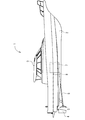
以下に、本願発明を具体化した第1実施形態を図面(図1〜図7)に基づいて説明する。図1に示すように、船舶であるプレジャーボート1は、船体2と、船体2の上面中央側に配置したキャビン3と、船体2の船底後尾側に設けた舵4と、船体2の船底後尾側のうち舵4の前方に配置したプロペラ5とを備えている。キャビン3内は操縦部になっている。船体2の船底後尾側に、プロペラ5を回転させる推進軸6(プロペラ軸)を軸支している。推進軸6の突出端側にプロペラ5を取り付けている。
Below, 1st Embodiment which actualized this invention is described based on drawing (FIGS. 1-7). As shown in FIG. 1, a pleasure boat 1 that is a ship includes a
詳細な図示は省略するが、キャビン3内には、操舵によって船体2の進行方向を左右に変更させる操舵ハンドルと、船体2の進行方向を前進と後進とに切換操作する前後進操作具としての前後進レバー7(図4参照)と、船体2を微速航行させる微速航行操作具としてのトローリングレバー8(図4参照)と、後述するエンジン10の出力回転数を設定保持する速度操作具としてのスロットルレバー9(図4参照)とを設けている。なお、各操作具としてはレバー式のものに限らず、ダイヤル式といった他の形態のものでもよい。
Although detailed illustration is omitted, the
船体2内には、プロペラ5の駆動源である主機関としてのエンジン10と、エンジン10の回転動力を推進軸6経由でプロペラ5に伝達する減速逆転機11とを設けている。エンジン10から減速逆転機11を経由して推進軸6に伝わった回転動力によって、プロペラ5が回転駆動する。
In the
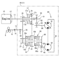
図2及び図3に示す如く、減速逆転機11は、エンジン10のフライホイル12に連結される入力軸13と、カップリング14を介して推進軸6に連結される出力軸15と、入力軸13から出力軸15に向けての前進方向の駆動力を継断する前進クラッチ16と、入力軸13から出力軸15に向けての後進方向の駆動力を継断する後進クラッチ17と、油圧ポンプ61及び油圧モータ62を有する油圧無段変速機(Hydro static transmission;「HST」)60とを備えている。
As shown in FIGS. 2 and 3, the
入力軸13と出力軸15とは、減速逆転機11のハウジング19から突き出すように設けている。入力軸13はハウジング19の正面上部に回転可能に軸支している。出力軸15はハウジング19の背面下部に回転可能に軸支している(図2に出力軸15側のみ示す)。前進クラッチ16及び後進クラッチ17を構成する前後進切換機構18は、減速逆転機11のハウジング19内に収容している。ハウジング19のうち出力軸15の上方には、後述する油圧無段変速機60を構成する油圧ポンプ61及び油圧モータ62を装着している。
The
前進クラッチ16及び後進クラッチ17は湿式多板形の油圧式摩擦クラッチである。前進クラッチ16は、入力軸13と平行状に延びる前進クラッチ軸21上にあり、且つ、スチールプレートと摩擦板とを交互に配置した構造になっている。前進クラッチ16は、スチールプレート付きの前進外ケース16aと、スチールプレートに圧接可能な摩擦板付きの前進内ハブ16bと、作動油圧で圧接力を発生させる前進クラッチシリンダ16cとを備えている。前進外ケース16aは前進クラッチ軸21に固着している。前進内ハブ16bは前進クラッチ軸21に回転可能に被嵌している。前進内ハブ16bの一端側を前進外ケース16aの内周側に差し入れている。前進内ハブ16bの外周側に前進ギヤ22を一体形成している。前進クラッチ軸21に前進減速ギヤ23を固着している。
The
後進クラッチ17は、入力軸13上にあり、且つ、前進クラッチ16と同様にスチールプレートと摩擦板とを交互に配置した構造になっている。後進クラッチ17は、スチールプレート付きの後進外ケース17aと、スチールプレートに圧接可能な摩擦板付きの後進内ハブ17bと、作動油圧で圧接力(クラッチ圧)を発生させる後進クラッチシリンダ17cとを備えている。後進外ケース17aは入力軸13に固着している。後進内ハブ17bは入力軸13に回転可能に被嵌している。後進内ハブ17bの一端側を後進外ケース17aの内周側に差し入れている。後進外ケース17aの外周側に中継ギヤ24を一体形成している。後進内ハブ17bの他端側に後進減速ギヤ25を一体形成している。
The reverse clutch 17 is on the
中継ギヤ24は、前進クラッチ16の前進ギヤ22と常時噛み合っている。前進減速ギヤ23及び後進減速ギヤ25は、出力軸15のうち減速逆転機11のハウジング19内の部位に固着した減速出力ギヤ26に常時噛み合っている。前進減速ギヤ23、後進減速ギヤ25及び減速出力ギヤ26は、固定減速比の減速ギヤ機構を構成している。出力軸15の回転動力は、各減速ギヤ23,25と減速出力ギヤ26との間で固定減速比に減速される。
The
減速逆転機11は、出力軸15を低回転させる微速航行用の駆動源として、油圧無段変速機60を備える。油圧無段変速機60は、可変容量形の油圧ポンプ61と定容量形の油圧モータ62とを油圧閉回路63によって流体的に接続したものである。そして、油圧ポンプ61の斜板角を変更することにより、油圧ポンプ61から吐出される作動油の流れと流量を変更することで、前進(油圧モータ62の正転)、後進(油圧モータ62の逆転)及び中立状態に切り換えると共に、油圧モータ62のモータ回転数すなわちプロペラ5回転数を調整できる。詳細な図示は省略するが、油圧閉回路63にチェック弁を介してチャージ油路を接続し、チャージ油路から油圧閉回路63内に作動油を補充するように構成している。なお、油圧モータ62を可変容量形にしてもよい。
The
入力軸13は、入力側増速ギヤ52が固着された中継軸51と、中継クラッチ50を介して継断可能に連結している。油圧ポンプ61のポンプ入力軸64に、出力側増速ギヤ53が固着されており、出力側増速ギヤ53が入力側増速ギヤ52と噛合することで、中継クラッチ50が接続されたとき、入力軸13からの回転動力が、中継軸51、入力側増速ギヤ52及び出力側増速ギヤ53を介して油圧ポンプ61に伝達される。
The
油圧モータ62のモータ出力軸65の先端側にはHST入力側ギヤ67を固着している。前進クラッチ軸21は、湿式多板形の油圧式摩擦クラッチであるHSTクラッチ66を介して、HST入力側ギヤ68と継断可能に接続されている。HSTクラッチ66は、前進クラッチ軸21上にあり、且つ、スチールプレートと摩擦板とを交互に配置した構造になっている。油圧無段変速機60及びHSTクラッチ66によって、微速航行における前進、中立又は後進の出力を設定する微速航行機構が構成されている。
An HST
HSTクラッチ66は、スチールプレート付きのHST外ケース66aと、スチールプレートに圧接可能な摩擦板付きのHST内ハブ66bと、作動油圧で圧接力を発生させるHSTクラッチシリンダ66cとを備えている。HST外ケース66aは前進クラッチ軸21に固着している。HST内ハブ66bは前進クラッチ軸21に回転可能に被嵌している。HST内ハブ66bの一端側をHST外ケース66aの内周側に差し入れている。HST内ハブ66bの外周側にHST入力側ギヤ68を一体形成し、HST入力側ギヤ68がHST入力側ギヤ67と噛合している。
The
キャビン3内にある前後進レバー7を前後進又は中立操作すると、作動油の供給先が前進クラッチ16(前進クラッチシリンダ16c)、後進クラッチ17(後進クラッチシリンダ17c)又は中立のいずれかに切り換えられる。前後進レバー7を中立操作して前進クラッチ16と後進クラッチ17との両方を動力遮断状態にした場合、エンジン10の回転動力を出力軸15に伝達しない中立状態となる。
When the forward / reverse lever 7 in the
前後進レバー7を前進操作して前進クラッチ16を動力接続状態にした場合(作動油圧で前進外ケース16aのスチールプレート及び前進内ハブ16bの摩擦板を互いに圧接させた場合)、後進クラッチ17は動力遮断状態であるから、エンジン10の回転動力が、入力軸13の中継ギヤ24から前進ギヤ22、前進クラッチ16及び前進減速ギヤ23を介して減速出力ギヤ26に伝達される。その結果、船舶1は、エンジン10の回転動力を前進方向の出力として出力軸15に伝達する前進状態となる。通常航行時における船舶1の前進航行速度の調節はキャビン3内のスロットルレバー9によって行われる。
When the forward / reverse lever 7 is operated forward to bring the forward clutch 16 into a power connection state (when the steel plate of the forward
前後進レバー7を後進操作して後進クラッチ17を動力接続状態にした場合、前進クラッチ16は動力遮断状態であるから、エンジン10の回転動力が、入力軸13から後進クラッチ17及び後進減速ギヤ25を介して減速出力ギヤ26に伝達される。その結果、船舶1は、エンジン10の回転動力を後進方向の出力として出力軸15に伝達する後進状態となる。通常航行時における船舶1の後進航行速度の調節もスロットルレバー9によって行われる。
When the forward / reverse lever 7 is operated backward to place the reverse clutch 17 in the power connected state, the
前進クラッチ16及び後進クラッチ17のいずれかが接続状態にある場合、少なくともHSTクラッチ66が動力遮断状態となっており、油圧無段変速機60における油圧モータ62からの動力が出力軸15に伝達されない。このとき、中継クラッチ50をも動力遮断状態として、入力軸13と中継軸51とを非連結状態とすることで、油圧無段変速機60における油圧ポンプ61への動力伝達を遮断するものとしてもよい。これにより、通常航行時において、油圧無段変速機60を介した動力が不要となる場合に、エンジン10にかかる負荷を低減して、燃費を向上できる。
When either the forward clutch 16 or the reverse clutch 17 is in a connected state, at least the
キャビン3内にあるトローリングレバー8の前後進操作によって、中継クラッチ50及びHSTクラッチ66を動力接続状態にすると共に、アクチュエータ等の斜板制御部55(図4参照)を介して油圧ポンプ61の斜板角が変更調節される。油圧ポンプ61の斜板角を変更調節することによって、油圧モータ62の回転数又は回転方向がそれぞれ変更され、出力軸15ひいてはプロペラ5が正逆の低回転で駆動する。また、トローリングレバー8の中立操作によって、HSTクラッチ66を動力遮断状態にすると共に、斜板制御部55を介して油圧ポンプ61の斜板角をゼロにして油圧モータ62の出力を停止させ、出力軸15ひいてはプロペラ5への動力伝達を停止する。
By operating the trolling
前後進レバー7を中立操作して前進クラッチ16及び後進クラッチ17の両方を動力遮断状態にした場合にトローリングレバー8を前後進操作すれば、中継クラッチ50及びHSTクラッチ66が動力接続状態に切り換わるように構成している。すなわち、前後進切換機構18が中立の場合に、中継クラッチ50及びHSTクラッチ66が動力接続状態になるのを許容するように構成している。また、前後進レバー7を前後進操作して前進クラッチ16又は後進クラッチ17のいずれかを動力接続状態にした場合は、トローリングレバー8を前後進操作しても、少なくともHSTクラッチ66が動力接続状態に切り換わらないように構成している。すなわち、前後進切換機構18が中立以外の場合は、少なくともHSTクラッチ66を動力遮断状態にするように構成している。
When the forward / reverse lever 7 is neutrally operated and both the
前後進レバー7が中立の状態でトローリングレバー8を前後進操作すると、中継クラッチ50及びHSTクラッチ66が動力接続状態になる。そのため、エンジン10からの回転動力が、中継クラッチ50を介して中継軸51に伝達され、入力側増速ギヤ52及び出力側増速ギヤ53の共動により、油圧ポンプ61のポンプ入力軸64が回転する。このとき、トローリングレバー8の操作量に応じた斜板制御部55の作動によって油圧ポンプ61の斜板角が調節され、油圧モータ62の回転数制御又は正逆転切換が実行される。
When the trolling
油圧モータ62の回転動力は、HST入力側ギヤ67及びHST出力側ギヤ68を介して、HSTクラッチ66のHST内ハブ66bに伝達される。このとき、HSTクラッチ66が接続状態となっているため、HST外ケース66aと共に前進クラッチ軸21がトローリングクラッチ軸として作用して正逆転する。そして、前進クラッチ軸21の前進減速ギヤ23が、トロ−リングクラッチギヤとして作用し、油圧モータ62から前進クラッチ軸21に伝達された回転動力が減速出力ギヤ26に伝達される。その結果、船舶1は、油圧モータ62の回転動力を前進又は後進方向の低回転出力として出力軸15、推進軸6ひいてはプロペラ5に伝達する前進又は後進微速航行状態となる。
The rotational power of the
図4に示すように、船舶1は、主としてエンジン10や減速逆転機11の作動全般の制御を司るコントローラ40を備える。コントローラ40は、詳細な図示は省略するが、各種演算処理や制御を実行するCPUのほか、制御プログラムやデータを記憶させるためのROM、制御プログラムやデータを一時的に記憶させるためのRAM、及び通信インターフェイス等を備えている。
As shown in FIG. 4, the marine vessel 1 includes a
コントローラ40の入力側には、前後進レバー7の操作位置を検出する前後進ポテンショ41、トローリングレバー8の操作位置を検出するトローリングポテンショ42、スロットルレバー9の操作位置を検出するスロットルポテンショ43、及び出力軸15の出力回転数を検出する回転検出センサ44、船首や船側や船尾などの船体2外周に設置されている複数のレーダユニット45、及び、GPS(全地球測位システム)衛星からの電波を受信して船体2位置を測位するGPSユニット46が電気的に接続されている。コントローラ40の出力側には、減速逆転機11における前進クラッチ16、後進クラッチ17、中継クラッチ50、及びHSTクラッチ66と、油圧無段変速機60における油圧ポンプ61の斜板角を変更する斜板制御部55と電気的に接続されている。
On the input side of the
操船システムを有するコントローラ40は、キーボードやマウスや操作ボタンなどの入力インターフェイス47、及びディスプレイなどの出力インターフェイス48と電気的に接続されている。操船者は、入力インターフェイス47を操作して、コントローラ40に船舶1の航路Rを入力することができるとともに、出力インターフェイス48の表示画面により航路Rと共に船体2位置や航行速度や船首の向きを把握できる。また、コントローラ40は、パーソナルコンピュータや外部メモリといった外部機器49と通信可能に構成されており、外部機器49を通じて、コントローラ40に船舶1の航路Rの入力が可能とされている。
The
レーダユニット45は、図5に示すように、障害物検知装置として、船舶1の船首、船側、船尾といった船体2外周部分に設置されており、船体2外側に発信したレーダの反射波を受けて、船体2と障害物70との距離だけでなく、障害物70に対して接近する速度を測定する。このレーダユニット45として、例えば、ミリ波レーダユニットを用いることで、悪天候などにおいても外環境からの影響が受け難いだけでなく、ドップラシフトが大きいことで障害物70との相対速度を高精度で測定できる。
As shown in FIG. 5, the
コントローラ40は、入力インターフェイス47により手動航行が選択されている場合は、上述した各レバー7〜9それぞれの操作による各ポテンショ42〜44の出力信号に従い、前進クラッチ16、後進クラッチ17、エンジン10の燃料噴射量、中継クラッチ50、及びHSTクラッチ66それぞれの継断、及び油圧ポンプ61における斜板角などを制御して、船体2の前後進及び航行速度を制御する。なお、不図示ではあるが、コントローラ40は、操舵ハンドルの操舵角度を受け、操舵角度に応じて舵4の角度を振ることで、操舵ハンドルの操作量に合わせて船体2の航行方向を調整する。
When manual navigation is selected by the
また、コントローラ40は、入力インターフェイス47により自動航行が選択されている場合は、予め入力された航路Rにより設定された航行速度で航行するように、予め記憶している電子海図とGPSユニット46からの測位情報から船体2位置を把握し、前進クラッチ16、後進クラッチ17、エンジン10の燃料噴射量、中継クラッチ50、及びHSTクラッチ66それぞれの継断、及び油圧ポンプ61における斜板角などを制御して、船体2の前後進及び航行速度を制御する。同様に、不図示ではあるが、コントローラ40は、航路Rより船体2位置に応じた航行方向を確認して、舵4の向きを制御することで、設定された航路R上を航行するように船体2の航行方向を調整する。
Further, when automatic navigation is selected by the
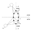
コントローラ40は、図6に示す航路Rに従って自動航行を実行している場合、GPSユニット46からの測位情報より、通常航行で設定された通常航行用航路R1上に船体2位置があることを確認すると、少なくともHSTクラッチ66を遮断状態とする。そして、コントローラ40は、通常航行用航路R1における船体2位置で設定された船舶1の航行方向と航行速度にあわせて、前進クラッチ16及び後進クラッチ17のいずれかを接続状態とするとともに、エンジン10の燃料噴射量を調整してエンジン10の回転速度を設定する。このとき、コントローラ40は、斜板制御部55により油圧ポンプ61の斜板角を中立とする。
When performing automatic navigation according to the route R shown in FIG. 6, the
また、コントローラ40は、GPSユニット46からの測位情報より、微速航行で設定された微速航行用航路R2上に船体2位置があることを確認すると、前進クラッチ16及び後進クラッチ17を共に遮断状態とする一方で、中継クラッチ50及びHSTクラッチ66を共に接続状態とする。そして、コントローラ40は、微速航行用航路R2における船体2位置で設定された船舶1の航行方向と航行速度にあわせて、斜板制御部55を通じて、油圧ポンプ61の斜板角を設定する。
Further, when the
コントローラ40は、船体2周辺に存在する障害物70との衝突を回避するための衝突回避制御を実行する。このとき、コントローラ40は、船舶1の航行方向側に障害物70の存在を認識すると、船舶1の航行方向(減速逆転機11の回転出力)を反転させるとともに、障害物70と船体2との距離及び船舶1の航行速度に応じた航行速度に切り換えて、船体2を停止させる。コントローラ40は、手動航行又は自動航行を実行している際に、衝突回避制御により操船操作を支援できるため、障害物70の多い海域や離発着の多い港湾であっても、障害物70との衝突を確実に回避でき、操船者の操作容易性を向上できるだけでなく、事故のない自動航行が可能となる。
The
また、船体2と障害物70との位置関係、障害物70との距離、航行方向、及び航行速度に基づいて、前進、後進、及び中立の動作状態だけでなく、通常航行又は微速航行における航行速度を設定できる。そのため、例えば、微速航行を切り換えて船体2位置を定点位置に維持する場合において、漂流物などの障害物70が船体2周辺に出現した際に、障害物70との衝突を最低限に抑えながら、船体2位置を定点位置に維持させることができる。
Further, based on the positional relationship between the
このとき、コントローラ40は、船舶1の航行方向側の障害物70と船体2との距離が所定距離Dthよりも遠い場合は、航行速度の遅い微速航行により減速逆転機11の出力を反転させ、船体2を停止させる。また、コントローラ40は、船舶1の航行方向側の障害物70と船体2との距離が所定距離Dthよりも近く、且つ、船舶1の航行速度が所定速度Vthよりも速い場合は、航行速度の速い通常航行により減速逆転機11の出力を反転させ、船体2を停止させる。
At this time, when the distance between the
コントローラ40は、障害物70との距離に基づいて、停止させる航行速度を切り換えるように構成しているため、障害物70との距離が遠い場合においては、船舶1の航行状態と障害物70との位置関係により最適な操船操作を実行できる。一方、障害物70との距離が近い場合においては、急速に船体2を停止させることで、障害物70との衝突を緊急避難的に回避できるために、安全に航行できる。
Since the
また、コントローラ40は、船舶1の航行速度に基づいて、停止させる航行速度を切り換えるように構成しているため、航行速度が遅く、障害物70にゆっくりと近づいている場合においては、船舶1の航行状態と障害物70との位置関係により最適な操船操作を実行できる。一方、航行速度が速く、障害物70に急速に近づいている場合においては、急速に船体2を停止させることで、障害物70との衝突を緊急避難的に回避できるために、安全に航行できる。
Further, since the
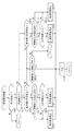
コントローラ40は、図7のフローチャートに示す如く、レーダユニット45からの信号により障害物70を確認すると(STEP1でYes)、船舶1の航行方向が前進方向であり(STEP2でYes)、障害物70が船体2の前方側(船体2の前方位置又は左右側方の前側位置)に位置しているときに(STEP3でYes)、障害物70との距離が所定距離Dthより遠い場合は(STEP4でNo)、船舶1の航行方向を後進方向に反転させるとともに、微速航行により船体2を停止させる(STEP5)。すなわち、船舶1の前進速度に関係なく、船体2に遠い障害物70に近づいている場合には、船舶1の後進航行を微速航行により制御するよう、減速逆転機11に対して、中継クラッチ50及びHSTクラッチ66を接続するとともに油圧ポンプ61の斜板角度を設定して、船体2を停止させる(微速後進停止)。このとき、障害物70との距離が短いほど船舶1の後進速度を速くするように設定するものとしてもよい。そして、船体2が停止すると、コントローラ40は、前進クラッチ16、後進クラッチ17、中継クラッチ50、及びHSTクラッチ66それぞれを切断状態として、減速逆転機11を中立状態とする(STEP8)。
As shown in the flowchart of FIG. 7, when the
また、コントローラ40は、船舶1の前進航行中に、船体2の前方側に位置する障害物70との距離が所定距離Dth以下となる場合は(STEP4でYes)、船舶1の航行速度に基づいて、船舶1の後進速度を設定する(STEP5〜7)。このとき、船舶1の航行速度が所定速度Vthより遅い場合は(STEP6でNo)、船舶1の航行方向を後進方向に反転させるとともに、微速航行により船体2を停止させる(STEP5)。一方、船舶1の航行速度が所定速度Vth以上となる場合は(STEP6でYes)、船舶1の航行方向を後進方向に反転させるとともに、通常航行により船体2を停止させる(STEP7)。
Further, when the distance between the
すなわち、船舶1の前進速度が速く、船体2に近い障害物70に速く近づいている場合に、船舶1の後進航行を通常航行により制御するよう、減速逆転機11に対して、後進クラッチ17を接続するとともにエンジン10の出力回転数を設定して、船体2を停止させる(通常後進停止)。一方、船舶1の前進速度が遅い場合には、船舶1の後進航行を微速航行により制御するよう、減速逆転機11に対して、中継クラッチ50及びHSTクラッチ66を接続するとともに油圧ポンプ61の斜板角度を設定して、船体2を停止させる(微速後進停止)。このとき、障害物70との距離が短いほど船舶1の後進速度を速くするように設定するものとしてもよい。また、通常航行により船体2を停止させる場合においては、障害物70との距離に長短に関わらず、最高速度による後進航行(全速後進)により船体2を停止させるものとしてもよい。そして、船体2が停止すると、コントローラ40は、減速逆転機11を中立状態とする(STEP8)。
That is, when the forward speed of the ship 1 is high and the
更に、コントローラ40は、船舶1の後進航行中に(STEP2でNo)、障害物70が船体2の後方側(船体2の後方位置又は左右側方の後側位置)に位置しているときに(STEP9でYes)、障害物70との距離が所定距離Dthより遠い場合は(STEP10でNo)、船舶1の航行方向を前進方向に反転させるとともに、微速航行により船体2を停止させる(STEP11)。すなわち、船舶1の後進速度に関係なく、船体2から遠い障害物70に近づいている場合には、船舶1の前進航行を微速航行により制御して船体2を停止させる(微速前進停止)。このとき、障害物70との距離が短いほど船舶1の前進速度を速くするように設定するものとしてもよい。そして、船体2が停止すると、コントローラ40は、減速逆転機11を中立状態とする(STEP8)。
Further, the
また、コントローラ40は、船舶1の後進航行中に、船体2の後方側に位置する障害物70との距離が所定距離Dth以下となる場合は(STEP10でYes)、船舶1の航行速度に基づいて、船舶1の前進速度を設定する(STEP11〜13)。このとき、船舶1の航行速度が所定速度Vthより遅い場合は(STEP12でNo)、減速逆転機11を中立状態とする(STEP8)。これにより、障害物70が船体2の船尾側に近い場合には、船底後尾側のプロペラ5の回転を停止して、障害物70のプロペラ5に対する巻き込みを防止できる。一方、船舶1の航行速度が所定速度Vth以上となる場合は(STEP12でYes)、船舶1の航行方向を前進方向に反転させるとともに、通常航行により船体2を停止させる(STEP13)。
Further, when the distance from the
すなわち、船舶1の後進速度が速く、船体2に近い障害物70に速く近づいている場合に、船舶1の前進航行を通常航行により制御するよう、減速逆転機11に対して、前進クラッチ16を接続するとともにエンジン10の出力回転数を設定して、船体2を停止させる(通常前進停止)。このとき、障害物70との距離が短いほど船舶1の前進速度を速くするように設定するものとしてもよいし、障害物70との距離に長短に関わらず、最高速度による前進航行(全速前進)により船体2を停止させるものとしてもよい。そして、船体2が停止すると、コントローラ40は、減速逆転機11を中立状態とする(STEP8)。
That is, when the reverse speed of the ship 1 is high and the
また、コントローラ40は、船舶1の前進航行中に、船体2の後方側に障害物70が位置する場合に(STEP3でNo)、障害物70との距離が所定距離Dth以下となるとき(STEP14でYes)、減速逆転機11を中立状態とする(STEP8)。これにより、障害物70が船体2の船尾側に近い場合には、船底後尾側のプロペラ5の回転を停止して、障害物70のプロペラ5に対する巻き込みを防止できる。一方、船舶1の前進航行中に、船体2の後方側の障害物70との距離が所定距離Dthより長い場合(STEP14でNo)、又は、船舶1の後進航行中に、船体2の前方側に障害物70を確認した場合は(STEP9でNo)、コントローラ40は、船舶1における現状の航行状態を維持させる。
Further, when the
なお、コントローラ40は、STEP5における微速後進停止状態、STEP7における通常後進停止状態、STEP11における微速前進停止状態、又はSTEP13における通常前進停止状態に移行する場合、船舶1の航行方向に障害物70があることを示す警告を、出力インターフェイス48により報知させる。このとき、コントローラ40は、移行する動作状態を出力インターフェイス48に報知させるものとしてもよく、また、障害物70との距離及び相対速度を出力インターフェイス48に表示させるものとしてもよい。また、コントローラ40は、STEP1で障害物70を確認した際に、船舶1の航行方向及び航行速度と、船体2に対する障害物70の距離、相対位置、及び相対速度とを表示し、操船者に障害物70との衝突可能性を可視化させるものとしてもよい。
The
次に、図8のフローチャートを参照して、第2実施形態となる船舶1の操船システムにおける衝突回避制御について、以下に説明する。図8に示す如く、本実施形態においては、コントローラ40は、船舶1の後進航行中、船体2の後方側に位置する障害物70との距離が所定距離Dth以下となる場合に(STEP10でYes)、船舶1の航行速度が所定速度Vthより遅いと(STEP12でNo)、船舶1の航行方向を前進方向に反転させるとともに、微速航行により船体2を停止させる(STEP11)。
Next, with reference to the flowchart of FIG. 8, the collision avoidance control in the boat maneuvering system of the ship 1 which is 2nd Embodiment is demonstrated below. As shown in FIG. 8, in the present embodiment, the
すなわち、船舶1の後進速度が遅く、船体2に近い障害物70にゆっくりと近づいている場合に、船舶1の前進航行を微速航行により制御して船体2を停止させる(微速前進停止)。このとき、障害物70との距離が短いほど船舶1の前進速度を速くするように設定するものとしてもよい。そして、船体2が停止すると、コントローラ40は、減速逆転機11を中立状態とする(STEP8)。
That is, when the backward speed of the ship 1 is slow and the
また、コントローラ40は、船舶1の前進航行中に、船体2の後方側に障害物70が位置する場合に(STEP3でNo)、又は、船舶1の後進航行中に、船体2の前方側に障害物70が位置する場合に(STEP9でNo)、障害物70との距離が所定距離Dth以下となるとき(STEP14でYes)、減速逆転機11を中立状態とする(STEP8)。すなわち、船舶1の航行方向と逆側に障害物70がある場合に、障害物70との所定距離Dthが近くなっているときに、減速逆転機11を中立状態として、船舶1を惰性航行させる。
Further, the
次に、図9のフローチャートを参照して、第3実施形態となる船舶1の操船システムにおける衝突回避制御について、以下に説明する。図9に示す如く、本実施形態においては、コントローラ40は、船舶1の後進航行中、船体2の後方側に位置する障害物70との距離が所定距離Dth以下となる場合に(STEP10でYes)、減速逆転機11を中立状態とする(STEP8)。すなわち、船舶1の後進速度に関係なく、船体2に近い障害物70に近づいている場合には、減速逆転機11を中立状態として、船舶1を惰性航行させる。
Next, with reference to the flowchart of FIG. 9, the collision avoidance control in the ship maneuvering system for the ship 1 according to the third embodiment will be described below. As shown in FIG. 9, in this embodiment, the
なお、本願発明における各部の構成は図示の実施形態に限定されるものではなく、例えば、図10に示す如く、油圧無段変速機60の代わりに電動モータ80を微速航行用の駆動源として用いる等、本願発明の趣旨を逸脱しない範囲で種々変更可能である。
The configuration of each part in the present invention is not limited to the illustrated embodiment. For example, as shown in FIG. 10, an
1 プレジャーボート(船舶)
2 船体
5 プロペラ
7 前後進レバー
8 トローリングレバー
9 スロットルレバー
10 エンジン(主機関)
11 減速逆転機
15 出力軸
16 前進クラッチ
17 後進クラッチ
18 前後進切換機構
40 コントローラ
41 前後進ポテンショ
42 トローリングポテンショ
43 スロットルポテンショ
44 回転検出センサ
45 レーダユニット
46 GPSユニット
47 入力インターフェイス
48 出力インターフェイス
49 外部機器
50 中継クラッチ
55 斜板制御部
60 油圧無段変速機
61 油圧ポンプ
62 油圧モータ
66 HSTクラッチ
80 電動モータ
1 Pleasure boat (ship)
2
11
Claims (7)
前記船舶の船体に障害物を検知する障害物検知装置が設けられており、
前記船体に対する前記障害物の位置、前記船舶の航行方向、前記船舶の航行速度、及び前記障害物と前記船体との距離に基づき、前進、中立又は後進のいずれかに設定するとともに航行速度の維持又は切換を実行することを特徴とする操船システム。 In a ship maneuvering system that controls the navigation of a ship that switches the power of the main engine to forward, neutral or reverse output by a speed reducer and reverse gear,
An obstacle detection device for detecting an obstacle on the hull of the ship is provided,
Based on the position of the obstacle relative to the hull, the navigation direction of the ship, the navigation speed of the ship, and the distance between the obstacle and the hull, it is set to either forward, neutral, or reverse and the navigation speed is maintained. Alternatively, a marine vessel maneuvering system that performs switching.
A ship equipped with a controller equipped with the boat maneuvering system according to any one of claims 1 to 6 in the hull.
Priority Applications (3)
| Application Number | Priority Date | Filing Date | Title |
|---|---|---|---|
| JP2016072227A JP2017178242A (en) | 2016-03-31 | 2016-03-31 | Maneuvering system, and ship |
| EP17160066.1A EP3225534A1 (en) | 2016-03-31 | 2017-03-09 | Watercraft steering system and watercraft |
| US15/468,716 US20170285645A1 (en) | 2016-03-31 | 2017-03-24 | Watercraft steering system and watercraft |
Applications Claiming Priority (1)
| Application Number | Priority Date | Filing Date | Title |
|---|---|---|---|
| JP2016072227A JP2017178242A (en) | 2016-03-31 | 2016-03-31 | Maneuvering system, and ship |
Publications (1)
| Publication Number | Publication Date |
|---|---|
| JP2017178242A true JP2017178242A (en) | 2017-10-05 |
Family
ID=58266438
Family Applications (1)
| Application Number | Title | Priority Date | Filing Date |
|---|---|---|---|
| JP2016072227A Pending JP2017178242A (en) | 2016-03-31 | 2016-03-31 | Maneuvering system, and ship |
Country Status (3)
| Country | Link |
|---|---|
| US (1) | US20170285645A1 (en) |
| EP (1) | EP3225534A1 (en) |
| JP (1) | JP2017178242A (en) |
Cited By (23)
| Publication number | Priority date | Publication date | Assignee | Title |
|---|---|---|---|---|
| KR20200070758A (en) * | 2018-12-10 | 2020-06-18 | ㈜버틀러네트워크 | System for sailing unmanned ship using infrared camera and method thereof |
| JP2020097406A (en) * | 2018-11-21 | 2020-06-25 | ブランズウィック コーポレーション | System and method for proximity sensing for ocean vessel |
| JP2021008174A (en) * | 2019-06-28 | 2021-01-28 | 古野電気株式会社 | Hull control device, hull control method, and hull control program |
| US10926855B2 (en) | 2018-11-01 | 2021-02-23 | Brunswick Corporation | Methods and systems for controlling low-speed propulsion of a marine vessel |
| CN112874750A (en) * | 2021-01-18 | 2021-06-01 | 谢党国 | Variable-speed ship propeller capable of steering quickly |
| US11198494B2 (en) | 2018-11-01 | 2021-12-14 | Brunswick Corporation | Methods and systems for controlling propulsion of a marine vessel to enhance proximity sensing in a marine environment |
| US11257378B2 (en) | 2019-01-31 | 2022-02-22 | Brunswick Corporation | Marine propulsion control system and method |
| CN114384520A (en) * | 2022-03-24 | 2022-04-22 | 中国人民解放军火箭军工程大学 | Method for realizing refined radar imaging of sea surface ship by using maneuvering platform |
| JP2022089743A (en) * | 2020-12-04 | 2022-06-16 | 財團法人船舶▲曁▼▲海▼洋▲産▼▲業▼研發中心 | Auxiliary correction system of marine vessel and operation system thereof |
| US11373537B2 (en) | 2018-12-21 | 2022-06-28 | Brunswick Corporation | Marine propulsion control system and method with collision avoidance override |
| US11403955B2 (en) | 2018-12-14 | 2022-08-02 | Brunswick Corporation | Marine propulsion control system and method with proximity-based velocity limiting |
| US11436927B2 (en) | 2018-11-21 | 2022-09-06 | Brunswick Corporation | Proximity sensing system and method for a marine vessel with automated proximity sensor location estimation |
| US11480966B2 (en) | 2020-03-10 | 2022-10-25 | Brunswick Corporation | Marine propulsion control system and method |
| WO2022239145A1 (en) * | 2021-05-12 | 2022-11-17 | 日本電信電話株式会社 | Fixed-point observation device and fixed-point observation system |
| JP2023503566A (en) * | 2019-11-27 | 2023-01-31 | エスティーエックスエンジン カンパニー リミテッド | Propulsion and braking system using clutch |
| US11643180B2 (en) | 2019-09-13 | 2023-05-09 | Furuno Electric Company Limited | Ship speed control device, ship speed controlling method, and ship speed control program |
| US11702178B2 (en) | 2019-01-31 | 2023-07-18 | Brunswick Corporation | Marine propulsion control system, method, and user interface for marine vessel docking and launch |
| US11794865B1 (en) | 2018-11-21 | 2023-10-24 | Brunswick Corporation | Proximity sensing system and method for a marine vessel |
| US11866142B2 (en) | 2019-09-13 | 2024-01-09 | Furuno Electric Company Limited | Hull control device, hull controlling method, and hull control program |
| US11866141B2 (en) | 2019-06-27 | 2024-01-09 | Furuno Electric Company Limited | Device, method, and program for controlling ship body |
| US11884371B2 (en) | 2019-07-05 | 2024-01-30 | Furuno Electric Company Limited | Device, method, and program for controlling ship body |
| JP7441776B2 (en) | 2020-11-18 | 2024-03-01 | 三菱造船株式会社 | Ships and how to navigate them |
| JP7475257B2 (en) | 2018-11-21 | 2024-04-26 | ブランズウィック コーポレーション | Proximity sensing system and method for marine vessels - Patents.com |
Families Citing this family (4)
| Publication number | Priority date | Publication date | Assignee | Title |
|---|---|---|---|---|
| EP3476712B1 (en) * | 2017-03-31 | 2023-04-12 | Honda Motor Co., Ltd. | Navigation assistance system for ship |
| CN108469817B (en) * | 2018-03-09 | 2021-04-27 | 武汉理工大学 | Unmanned ship obstacle avoidance control system based on FPGA and information fusion |
| CN109460035B (en) * | 2018-12-18 | 2021-10-15 | 国家海洋局北海海洋工程勘察研究院(青岛环海海洋工程勘察研究院) | Secondary autonomous obstacle avoidance method for unmanned ship in high-speed state |
| CN114379718B (en) * | 2021-12-22 | 2023-05-30 | 南京联迪信息系统股份有限公司 | Method and system for early warning and rescuing in distress of pleasure boat |
Family Cites Families (5)
| Publication number | Priority date | Publication date | Assignee | Title |
|---|---|---|---|---|
| DE4036578C2 (en) * | 1990-11-16 | 1993-12-16 | Man Nutzfahrzeuge Ag | Method for decelerating a ship's propulsion, in particular during an emergency stop maneuver, and device for carrying out the method |
| JP2564610Y2 (en) | 1993-04-15 | 1998-03-09 | ヤンマーディーゼル株式会社 | Hydraulic control device for marine reduction reversing machine |
| US6273771B1 (en) * | 2000-03-17 | 2001-08-14 | Brunswick Corporation | Control system for a marine vessel |
| JP2002090171A (en) | 2000-09-13 | 2002-03-27 | Todaka Seisakusho:Kk | Automatic sea route retention device of ship |
| ITTO20030779A1 (en) * | 2003-10-03 | 2005-04-04 | Azimut S P A | COMMAND SYSTEM FOR BOATS. |
-
2016
- 2016-03-31 JP JP2016072227A patent/JP2017178242A/en active Pending
-
2017
- 2017-03-09 EP EP17160066.1A patent/EP3225534A1/en not_active Withdrawn
- 2017-03-24 US US15/468,716 patent/US20170285645A1/en not_active Abandoned
Cited By (35)
| Publication number | Priority date | Publication date | Assignee | Title |
|---|---|---|---|---|
| US10926855B2 (en) | 2018-11-01 | 2021-02-23 | Brunswick Corporation | Methods and systems for controlling low-speed propulsion of a marine vessel |
| US11198494B2 (en) | 2018-11-01 | 2021-12-14 | Brunswick Corporation | Methods and systems for controlling propulsion of a marine vessel to enhance proximity sensing in a marine environment |
| US11904996B2 (en) | 2018-11-01 | 2024-02-20 | Brunswick Corporation | Methods and systems for controlling propulsion of a marine vessel to enhance proximity sensing in a marine environment |
| US11436927B2 (en) | 2018-11-21 | 2022-09-06 | Brunswick Corporation | Proximity sensing system and method for a marine vessel with automated proximity sensor location estimation |
| JP2020097406A (en) * | 2018-11-21 | 2020-06-25 | ブランズウィック コーポレーション | System and method for proximity sensing for ocean vessel |
| JP2021011263A (en) * | 2018-11-21 | 2021-02-04 | ブランズウィック コーポレーション | Proximity sensing system and method for marine vessel |
| JP7475257B2 (en) | 2018-11-21 | 2024-04-26 | ブランズウィック コーポレーション | Proximity sensing system and method for marine vessels - Patents.com |
| US11794865B1 (en) | 2018-11-21 | 2023-10-24 | Brunswick Corporation | Proximity sensing system and method for a marine vessel |
| US11443637B2 (en) | 2018-11-21 | 2022-09-13 | Brunswick Corporation | Proximity sensing system and method for a marine vessel |
| KR102128085B1 (en) * | 2018-12-10 | 2020-07-09 | (주)버틀러네트워크 | System for sailing unmanned ship using infrared camera and method thereof |
| KR20200070758A (en) * | 2018-12-10 | 2020-06-18 | ㈜버틀러네트워크 | System for sailing unmanned ship using infrared camera and method thereof |
| US11862026B2 (en) | 2018-12-14 | 2024-01-02 | Brunswick Corporation | Marine propulsion control system and method with proximity-based velocity limiting |
| US11403955B2 (en) | 2018-12-14 | 2022-08-02 | Brunswick Corporation | Marine propulsion control system and method with proximity-based velocity limiting |
| US11804137B1 (en) | 2018-12-21 | 2023-10-31 | Brunswick Corporation | Marine propulsion control system and method with collision avoidance override |
| US11373537B2 (en) | 2018-12-21 | 2022-06-28 | Brunswick Corporation | Marine propulsion control system and method with collision avoidance override |
| US11702178B2 (en) | 2019-01-31 | 2023-07-18 | Brunswick Corporation | Marine propulsion control system, method, and user interface for marine vessel docking and launch |
| US11600184B2 (en) | 2019-01-31 | 2023-03-07 | Brunswick Corporation | Marine propulsion control system and method |
| US11257378B2 (en) | 2019-01-31 | 2022-02-22 | Brunswick Corporation | Marine propulsion control system and method |
| US11866141B2 (en) | 2019-06-27 | 2024-01-09 | Furuno Electric Company Limited | Device, method, and program for controlling ship body |
| JP7261105B2 (en) | 2019-06-28 | 2023-04-19 | 古野電気株式会社 | Hull control device, hull control method, and hull control program |
| US11873067B2 (en) | 2019-06-28 | 2024-01-16 | Furuno Electric Company Limited | Device, method, and program for controlling ship body |
| JP2021008174A (en) * | 2019-06-28 | 2021-01-28 | 古野電気株式会社 | Hull control device, hull control method, and hull control program |
| US11884371B2 (en) | 2019-07-05 | 2024-01-30 | Furuno Electric Company Limited | Device, method, and program for controlling ship body |
| US11866142B2 (en) | 2019-09-13 | 2024-01-09 | Furuno Electric Company Limited | Hull control device, hull controlling method, and hull control program |
| US11643180B2 (en) | 2019-09-13 | 2023-05-09 | Furuno Electric Company Limited | Ship speed control device, ship speed controlling method, and ship speed control program |
| JP7343252B2 (en) | 2019-11-27 | 2023-09-12 | エスティーエックスエンジン カンパニー リミテッド | Propulsion and braking system using clutch |
| JP2023503566A (en) * | 2019-11-27 | 2023-01-31 | エスティーエックスエンジン カンパニー リミテッド | Propulsion and braking system using clutch |
| US11480966B2 (en) | 2020-03-10 | 2022-10-25 | Brunswick Corporation | Marine propulsion control system and method |
| JP7441776B2 (en) | 2020-11-18 | 2024-03-01 | 三菱造船株式会社 | Ships and how to navigate them |
| JP7171825B2 (en) | 2020-12-04 | 2022-11-15 | 財團法人船舶▲曁▼▲海▼洋▲産▼▲業▼研發中心 | Auxiliary correction system for ships and its operation method |
| JP2022089743A (en) * | 2020-12-04 | 2022-06-16 | 財團法人船舶▲曁▼▲海▼洋▲産▼▲業▼研發中心 | Auxiliary correction system of marine vessel and operation system thereof |
| CN112874750A (en) * | 2021-01-18 | 2021-06-01 | 谢党国 | Variable-speed ship propeller capable of steering quickly |
| WO2022239145A1 (en) * | 2021-05-12 | 2022-11-17 | 日本電信電話株式会社 | Fixed-point observation device and fixed-point observation system |
| CN114384520B (en) * | 2022-03-24 | 2022-07-05 | 中国人民解放军火箭军工程大学 | Method for realizing refined radar imaging of sea surface ship by using maneuvering platform |
| CN114384520A (en) * | 2022-03-24 | 2022-04-22 | 中国人民解放军火箭军工程大学 | Method for realizing refined radar imaging of sea surface ship by using maneuvering platform |
Also Published As
| Publication number | Publication date |
|---|---|
| EP3225534A1 (en) | 2017-10-04 |
| US20170285645A1 (en) | 2017-10-05 |
Similar Documents
| Publication | Publication Date | Title |
|---|---|---|
| JP2017178242A (en) | Maneuvering system, and ship | |
| US8170734B2 (en) | Marine vessel maneuvering supporting apparatus and marine vessel including the same | |
| JP6947686B2 (en) | Ship propulsion system and ships | |
| JP6664171B2 (en) | Ship control equipment | |
| US11420716B2 (en) | Vessel propulsion system and vessel including the same | |
| KR102380469B1 (en) | Evacuation shipbuilding method in congested waters and avoidance shipbuilding system of one-axis two-barreled ship | |
| JP2015209144A (en) | Ship propulsion system and control method of propeller | |
| US20220374015A1 (en) | Marine vessel propulsion control system and marine vessel | |
| JP5634213B2 (en) | Ship propulsion device | |
| US20170274973A1 (en) | Boat | |
| US9709996B2 (en) | Boat maneuvering system | |
| JP2017161222A (en) | Contact avoidance device for small ships | |
| JP2017171262A (en) | Vessel | |
| US10479469B2 (en) | Steering system for an outboard motor | |
| JP2016159805A (en) | Ship | |
| US20220413499A1 (en) | Watercraft auto-docking system and watercraft auto-docking method | |
| US20160325812A1 (en) | Maneuvering system for watercraft | |
| JP7141777B1 (en) | Single-shaft, two-rudder vessel with automatic berthing function | |
| US11697485B2 (en) | Manoeuvring system for a vessel | |
| JP7145542B1 (en) | Steering system with steering angle correction function for single shaft and two rudder ships | |
| US20230331364A1 (en) | Marine vessel maneuvering system, and marine vessel | |
| JP2022160036A (en) | Navigation system for vessel |