JP7341908B2 - undercover - Google Patents
undercover Download PDFInfo
- Publication number
- JP7341908B2 JP7341908B2 JP2020003577A JP2020003577A JP7341908B2 JP 7341908 B2 JP7341908 B2 JP 7341908B2 JP 2020003577 A JP2020003577 A JP 2020003577A JP 2020003577 A JP2020003577 A JP 2020003577A JP 7341908 B2 JP7341908 B2 JP 7341908B2
- Authority
- JP
- Japan
- Prior art keywords
- vehicle
- inter
- tire
- tires
- undercover
- Prior art date
- Legal status (The legal status is an assumption and is not a legal conclusion. Google has not performed a legal analysis and makes no representation as to the accuracy of the status listed.)
- Active
Links
- 238000010276 construction Methods 0.000 claims 1
- 238000010586 diagram Methods 0.000 description 6
- 238000000034 method Methods 0.000 description 3
- 230000000694 effects Effects 0.000 description 2
- 239000012141 concentrate Substances 0.000 description 1
- 230000002452 interceptive effect Effects 0.000 description 1
- 230000004048 modification Effects 0.000 description 1
- 238000012986 modification Methods 0.000 description 1
- 239000011347 resin Substances 0.000 description 1
- 229920005989 resin Polymers 0.000 description 1
- 239000000725 suspension Substances 0.000 description 1
Images


Classifications
-
- Y—GENERAL TAGGING OF NEW TECHNOLOGICAL DEVELOPMENTS; GENERAL TAGGING OF CROSS-SECTIONAL TECHNOLOGIES SPANNING OVER SEVERAL SECTIONS OF THE IPC; TECHNICAL SUBJECTS COVERED BY FORMER USPC CROSS-REFERENCE ART COLLECTIONS [XRACs] AND DIGESTS
- Y02—TECHNOLOGIES OR APPLICATIONS FOR MITIGATION OR ADAPTATION AGAINST CLIMATE CHANGE
- Y02T—CLIMATE CHANGE MITIGATION TECHNOLOGIES RELATED TO TRANSPORTATION
- Y02T10/00—Road transport of goods or passengers
- Y02T10/80—Technologies aiming to reduce greenhouse gasses emissions common to all road transportation technologies
- Y02T10/88—Optimized components or subsystems, e.g. lighting, actively controlled glasses
Landscapes
- Body Structure For Vehicles (AREA)
Description
本発明は、車両の床下に空気抵抗低減のために設けられるアンダーカバーに関する。 The present invention relates to an undercover provided under the floor of a vehicle to reduce air resistance.
図13に示すように、車両の床下には、車両の床下全面をフラットな形状に近づけて車両床下を流れる空気の抵抗を抑制するために、アンダーカバー1が設定されている。 As shown in FIG. 13, an undercover 1 is provided under the floor of the vehicle in order to reduce the resistance of air flowing under the vehicle floor by making the entire underfloor area of the vehicle nearly flat.
しかし、図14に示すように、車両の幅方向外側端部にはフロントタイヤ101とリアタイヤ102が配設されているため、車両床下を流れる空気はタイヤ100によって流れが遮られてしまう。そのため、車両の幅方向中央部に比べてタイヤ100近傍(車両の幅方向外側端部とその近傍)における空気流れが少なくなり、車両の幅方向中央部へ流れが集中してしまう。その結果、車両床下から車両の後方へ流れる空気流量(出口流量)を増やして車両の空力性能を高める点で改善の余地がある。
However, as shown in FIG. 14, since
特開2016-222152号公報は、図15に示すように、左右のタイヤ100間に位置するタイヤ間部1a-1を有する主カバー(リアアンダーカバー)1aを、車両後方かつ上方に傾斜させており、タイヤ間部1a-1の下面高さが、主カバー1aの車両前側にある前側カバー(フロアアンダーカバー)1bの下面高さよりも高くなっている技術を開示している。かかる技術によれば、タイヤ間部1a-1が前側カバー1bと同じ下面高さとされている場合に比べて、タイヤ100間における流路断面積を増加させることができるため、タイヤ100間を流れる空気の流量を増やすことができ、その結果、車両床下から車両の後方へ流れる空気流量を増やすことができると考えられる。
As shown in FIG. 15, JP 2016-222152A discloses a main cover (rear undercover) 1a having an
しかし、上記公報開示の技術にあっても、車幅方向の全体にわたって均一にタイヤ間部1a-1を車両後方かつ上方に傾斜させているため、車両の幅方向中央部へ流れが集中してしまうという問題が依然として残る。
However, even with the technique disclosed in the above publication, since the
本発明の目的は、従来に比べて、タイヤ近傍における流量を増加させることができるアンダーカバーを提供することにある。 An object of the present invention is to provide an undercover that can increase the flow rate near the tire compared to the conventional one.
上記目的を達成する本発明はつぎの通りである。
(1) 左右のタイヤ間に位置するタイヤ間部を有する主カバーと、
前記主カバーの車両前側にある前側カバーと、
を有し、前記主カバーのタイヤ間部の下面高さが、前記前側カバーの下面高さよりも高くなっている、アンダーカバーであって、
前記タイヤ間部は、該タイヤ間部の車幅方向中央部を含むタイヤ間中央部と、該タイヤ間中央部の車幅方向の両外側にあり前記タイヤ間部の車幅方向外側端部を含むタイヤ間外側部と、を有しており、
前記タイヤ間外側部は、前記タイヤ間中央部よりも下面高さが高くなっている、アンダーカバー。
(2) 前記タイヤ間部の下面は、該タイヤ間部の少なくとも車両前後方向の中間部に、車幅方向と直交する断面視で車両上下方向と直交する直線状に延びる水平部を有している、(1)記載のアンダーカバー。
(3) 前記主カバーは、前記タイヤ間部の車両前側にある主カバー前部を有しており、該主カバー前部の下面は、車両後側かつ車両上方に傾斜している、(1)または(2)記載のアンダーカバー。
(4) 前記主カバーは、一部品構成である、(1)~(3)のいずれか1つに記載のアンダーカバー。
(5) 前記主カバーの車両後側にある後側カバーを、さらに有しており、
前記タイヤ間部の下面の車両後側端部は、前記後側カバーの下面の車両前側端部に向って車両後側かつ車両下方に傾斜している、(1)~(4)のいずれか1つに記載のアンダーカバー。
(6) 前記タイヤ間部は、左右のフロントタイヤ間と左右のリアタイヤ間の少なくともいずれか一方に設けられている、(1)~(5)のいずれか1つに記載のアンダーカバー。
The present invention that achieves the above object is as follows.
(1) A main cover having an inter-tire section located between the left and right tires;
a front cover located on the vehicle front side of the main cover;
, wherein the lower surface height of the inter-tire portion of the main cover is higher than the lower surface height of the front cover,
The inter-tire portion includes a central portion between the tires including a central portion in the vehicle width direction of the inter-tire portion, and an outer end portion of the inter-tire portion located on both outer sides in the vehicle width direction of the central portion between the tires. and an outer inter-tire portion including;
The undercover is configured such that the outer side portion between the tires has a higher lower surface height than the center portion between the tires.
(2) The lower surface of the area between the tires has a horizontal portion extending in a straight line orthogonal to the vertical direction of the vehicle in a cross-sectional view orthogonal to the vehicle width direction, at least at the intermediate portion of the area between the tires in the longitudinal direction of the vehicle. The undercover described in (1).
(3) The main cover has a front part of the main cover located on the front side of the vehicle between the tires, and the lower surface of the front part of the main cover is inclined toward the rear side of the vehicle and above the vehicle. ) or the undercover described in (2).
(4) The undercover according to any one of (1) to (3), wherein the main cover has a one-piece configuration.
(5) further comprising a rear cover located on the rear side of the vehicle of the main cover;
Any one of (1) to (4), wherein the rear end of the lower surface of the inter-tire portion is inclined toward the rear of the vehicle and downward of the vehicle toward the front end of the lower surface of the rear cover. Undercover mentioned in one.
(6) The undercover according to any one of (1) to (5), wherein the inter-tire portion is provided between at least one of the left and right front tires and between the left and right rear tires.
上記(1)~(6)のアンダーカバーでは、タイヤ間部の下面高さが、前側カバーの下面高さよりも高くなっている。そのため、タイヤ間部の下面高さが前側カバーの下面高さと同じかそれより低くされている場合に比べて、タイヤ間部における流路断面積を増やすことができ、車両床下を流れる空気の流量を増やすことができる。 In the undercovers (1) to (6) above, the lower surface height of the portion between the tires is higher than the lower surface height of the front cover. Therefore, compared to a case where the lower surface height between the tires is the same as or lower than the lower surface height of the front cover, it is possible to increase the cross-sectional area of the flow path between the tires, and the flow rate of air flowing under the vehicle floor. can be increased.
また、タイヤ間外側部が、タイヤ間中央部よりも下面高さが高くなっている。そのため、タイヤ間外側部の下面高さがタイヤ間中央部の下面高さと同じかそれより低い場合に比べて、タイヤ間外側部の流路断面積をタイヤ間中央部の流路断面積よりも大きくできる。その結果、タイヤ間外側部を流れる空気の流量を多くすることができ、車両の幅方向中央部へ流れが集中することを緩和できる。その結果、車両床下から車両の後方へ流れる空気流量(出口流量)を増やすことができ、車両の空力性能を高めることができる。また、タイヤ間外側部を流れる空気の流量を多くすることができるため、タイヤ後方での流れの乱れを縮小させることができ、この点でも車両の空力性能を高めることができる。 Further, the outer side portion between the tires has a higher lower surface height than the center portion between the tires. Therefore, compared to a case where the lower surface height of the outer part between the tires is the same as or lower than the lower surface height of the central part between the tires, You can make it bigger. As a result, it is possible to increase the flow rate of air flowing through the outer portion between the tires, and it is possible to alleviate the concentration of air flow toward the center portion in the width direction of the vehicle. As a result, the amount of air flowing from under the vehicle floor to the rear of the vehicle (exit flow rate) can be increased, and the aerodynamic performance of the vehicle can be improved. Furthermore, since the flow rate of air flowing through the outer side between the tires can be increased, turbulence in the flow behind the tires can be reduced, and the aerodynamic performance of the vehicle can also be improved in this respect.
上記(2)のアンダーカバーでは、タイヤ間部の下面が、タイヤ間部の少なくとも車両前後方向の中間部に、車幅方向と直交する断面視で車両上下方向と直交する直線状に延びる水平部を有している。そのため、タイヤ間部の下面がその車両前後方向の全体にわたって車両後側かつ車両上方に傾斜する場合に比べて、タイヤ間部における流路断面積を増やすことができ、車両床下を流れる空気の流量を増やすことができる。 In the undercover of (2) above, the lower surface of the space between the tires has a horizontal portion that extends in a straight line perpendicular to the vertical direction of the vehicle in a cross-sectional view perpendicular to the vehicle width direction, at least in the middle part of the space between the tires in the longitudinal direction of the vehicle. have. Therefore, compared to a case where the lower surface of the space between the tires slopes toward the rear of the vehicle and above the vehicle throughout the longitudinal direction of the vehicle, the cross-sectional area of the flow path between the tires can be increased, and the flow rate of air flowing under the vehicle floor increases. can be increased.
上記(3)のアンダーカバーでは、主カバー前部の下面が車両後側かつ車両上方に傾斜している。そのため、タイヤ間部が前側カバーよりも下面高さが高くなっている場合であっても、前側カバーに沿って流れる空気を、剥離することなくタイヤ間部に沿って流すことができる。 In the undercover (3) above, the lower surface of the front part of the main cover is inclined toward the rear of the vehicle and above the vehicle. Therefore, even if the lower surface height of the space between the tires is higher than that of the front cover, air flowing along the front cover can flow along the space between the tires without being separated.
上記(4)のアンダーカバーでは、主カバーが一部品構成であるため、主カバーが複数部品構成である場合に比べて、部品点数を削減できコスト上有利である。 In the undercover (4) above, since the main cover is composed of one part, the number of parts can be reduced and it is advantageous in terms of cost compared to the case where the main cover is composed of multiple parts.
上記(5)のアンダーカバーでは、タイヤ間部の下面の車両後側端部が、後側カバーの下面の車両前側端部に向って車両後側かつ車両下方に傾斜している。そのため、タイヤ間部が後側カバーよりも下面高さが高くなっている場合であっても、タイヤ間部に沿って流れる空気を、滑らかに後側カバーに沿って流すことができる。 In the undercover of (5) above, the vehicle rear side end of the lower surface of the inter-tire portion is inclined toward the vehicle front side end of the lower surface of the rear cover toward the vehicle rear side and vehicle downward direction. Therefore, even if the lower surface height of the inter-tire area is higher than that of the rear cover, the air flowing along the inter-tire area can flow smoothly along the rear cover.
以下に、図面を参照して、本発明実施例のアンダーカバー10を説明する。なお、図中UPは車両上方、FRは車両前方、OUTは車両幅方向の外方を示す。 Below, an undercover 10 according to an embodiment of the present invention will be described with reference to the drawings. In the figure, UP indicates the upper side of the vehicle, FR indicates the front of the vehicle, and OUT indicates the outer side in the vehicle width direction.
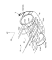
本発明実施例のアンダーカバー10は、図1に示すように、車両Vの床下に空気抵抗低減のために設けられる。アンダーカバー10は、特に限定されるものではないが、車両Vの床下の全面に設けられていることが望ましい。車両Vの床下全面にわたってアンダーカバー10による空気抵抗低減効果を得られるからである。 As shown in FIG. 1, an undercover 10 according to an embodiment of the present invention is provided under the floor of a vehicle V to reduce air resistance. Although the undercover 10 is not particularly limited, it is desirable that the undercover 10 be provided on the entire surface under the floor of the vehicle V. This is because the air resistance reduction effect of the undercover 10 can be obtained over the entire area under the floor of the vehicle V.
アンダーカバー10は、たとえば樹脂製である。アンダーカバー10は、主カバー20と、主カバー20の車両前側にある前側カバー30と、主カバー20の車両後側にある後側カバー40と、を有する。
The undercover 10 is made of resin, for example. The undercover 10 includes a
主カバー20は、一部品構成であってもよく、複数部品構成であってもよい。主カバー20が複数部品構成である場合、構成部品同士は互いに連結されて固定されている。主カバー20が複数部品構成である場合、主カバー20は車両前後方向に複数部品構成であってもよく(図7)、車両幅方向に複数部品構成であってもよい(図8)。また、主カバー20が複数部品構成である場合、図9に示すように、一方の構成部品から他方の構成部品へ空気が流れる際に流れが乱れることを抑制するために、隣り合う構成部品同士の少なくとも一方に、互いの距離が近づく方向に延びる延長部20aが形成されていることが望ましい。
The
主カバー20は、図2に示すように、左右のタイヤ100間に位置するタイヤ間部21と、タイヤ間部21の車両前側にある主カバー前部22と、を有する。
As shown in FIG. 2, the
タイヤ間部21は、左右のタイヤ100間に設けられている(位置している)。タイヤ100は、車両のフロントタイヤ101であってもよくリアタイヤ102であってもよく、フロントタイヤ101とリアタイヤ102の両方であってもよい。すなわち、タイヤ間部21は、左右のフロントタイヤ101間と左右のリアタイヤ102間の少なくともいずれか一方に設けられていればよい。なお、本発明実施例および図示例では、タイヤ100がリアタイヤ102であり、タイヤ間部21が左右のリアタイヤ102間のみに設けられる場合を例にとって説明する。
The
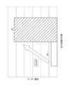
図4、図5に示すように、タイヤ間部21の上側には、車体または車体に搭載される部品からなる車体側部品Mが配設されている。車体側部品Mは、たとえば、リアモータやリアサスペンションメンバ等である。タイヤ間部21の下面高さは、前側カバー30の下面高さよりも高くなっている。そのため、車両床下を流れる空気の流路断面積(車両前後方向と直交する断面積)は、前側カバー30の下側よりもタイヤ間部21の下側の方が大となっている。タイヤ間部21の下面高さは、車体側部品Mに干渉しない制約内で、高くされている。
As shown in FIGS. 4 and 5, above the
図2に示すように、タイヤ間部21は、タイヤ間部21の車幅方向の中央部(中心部)Pを含むタイヤ間中央部21aと、タイヤ間中央部21aの車幅方向の両外側にありタイヤ間部21の車幅方向外側端部を含むタイヤ間外側部21bと、を有する。
As shown in FIG. 2, the
タイヤ間中央部21aの下面は、タイヤ間部21の少なくとも車両前後方向の中間部に、車幅方向と直交する断面視で車両上下方向と直交する直線状に延びる水平部21a1を有している。水平部21a1の車両前側端部は、主カバー前部22の車両後側端部に直接連なっている。水平部21a1の車両後側端部は、後側カバー40の下面の車両前側端部に向って車両後側かつ車両下方に傾斜する傾斜部21a2を介して、後側カバー40に連なっている。
The lower surface of the inter-tire
タイヤ間中央部21aは、タイヤ間中央部21aの車幅方向の全域にわたって一様な高さの下面を有していてもよく、タイヤ間中央部21aの車幅方向の両外側部21a3が車幅方向の中央部に比べて段差状または傾斜状に下面高さが高くなっていてもよい。
The inter-tire
タイヤ間外側部21bは、タイヤ間中央部21aよりも下面高さが高くなっている。タイヤ間外側部21bの下面は、タイヤ間部21の少なくとも車両前後方向の中間部に、車幅方向と直交する断面視で車両上下方向と直交する直線状に延びる水平部21b1を有している。タイヤ間外側部21bが少なくとも車両前後方向の中間部に水平部21b1を有しており、前述のようにタイヤ間中央部21aも少なくとも車両前後方向の中間部に水平部21a1を有しているため、タイヤ間部21の下面は、タイヤ間部21の少なくとも車両前後方向の中間部に水平部21b1,21a1を有している。
The inter-tire
タイヤ間外側部21bの水平部21b1の車両前側端部は、主カバー前部22の下面の車両後側端部に向って車両前側かつ車両下方に傾斜する前側傾斜部21b2を介して、主カバー前部22に連なっている。タイヤ間外側部21bの水平部21b1の車両後側端部は、後側カバー40の下面の車両前側端部に向って車両後側かつ車両下方に傾斜する後側傾斜部21b3を介して、後側カバー40に連なっている。後側傾斜部21b3は、一部で、タイヤ間中央部21aの傾斜部21a2とも連なっている。
The vehicle front side end of the horizontal portion 21b1 of the inter-tire
タイヤ間外側部21bの水平部21b1の車幅方向中央側端部は、タイヤ間中央部21aの下面の車幅方向外側端部に向って車両幅方向中央側かつ車両下方に傾斜する内側傾斜部21b4を介して、タイヤ間中央部21aに連なっている。図6に示すように、タイヤ間外側部21bの水平部21b1の車幅方向外側端部は、車両のホイールハウスの一部を形成するフェンダライナ110に連なっている。
The center end in the vehicle width direction of the horizontal portion 21b1 of the inter-tire
図2に示すように、主カバー前部22は、タイヤ間部21の車両前側で前側カバー30の車両後側にあり、タイヤ間部21と前側カバー30とを車両前後方向に連結している。主カバー前部22の下面は、車両後側かつ車両上方に傾斜している。
As shown in FIG. 2, the main cover
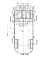
図4に示すように、前側カバー30は、主カバー前部22の車両前側端部から車両前側に延びて設けられている。前側カバー30は、フロアアンダーカバーといってもよく、主カバー前部22の車両前側端部からフロントタイヤ101間の車両後側端部またはその近傍まで設けられている。前側カバー30の下面は、前側カバー30の全面(ほぼ全面を含む)にわたってフラットとなっている。前側カバー30の車両前側には、第1、第2のエンジンアンダーカバー50,51が設けられている。第1のエンジンアンダーカバー50の車両前側端部は、車両のフロントバンパ120の下端部に連なっている。
As shown in FIG. 4, the
後側カバー40は、主カバー20の車両後側端部から車両後側に延びて設けられている。後側カバー40は、リアアンダーカバーといってもよく、主カバー20の車両後側端部から車両の後端部まで設けられている。後側カバー40の下面は、後側カバー40の全面(ほぼ全面を含む)にわたって車両後側かつ車両上方に傾斜する傾斜面となっている。後側カバー40の車両後側端部は、車両のリアバンパ130の下端部に連なっている。
The
つぎに、本発明実施例の作用、効果を説明する。 Next, the functions and effects of the embodiments of the present invention will be explained.
(A)図2に示すように、タイヤ間部21の下面高さが、前側カバー30の下面高さよりも高くなっている。そのため、タイヤ間部21の下面高さが前側カバー30の下面高さと同じかそれより低くされている場合に比べて、タイヤ間部21における流路断面積を増やすことができ、車両床下を流れる空気の流量を増やすことができる。
(A) As shown in FIG. 2, the lower surface height of the
(B)タイヤ間外側部21bが、タイヤ間中央部21aよりも下面高さが高くなっている。そのため、タイヤ間外側部21bの下面高さがタイヤ間中央部21aの下面高さと同じかそれより低い場合に比べて、タイヤ間外側部21bの流路断面積をタイヤ間中央部21aの流路断面積よりも大きくできる。その結果、タイヤ間外側部21bを流れる空気の流量を多くすることができ、車両の幅方向中央部へ流れが集中することを緩和できる。その結果、車両床下から車両の後方へ流れる空気流量(出口流量)を増やすことができ、車両の空力性能を高めることができる。また、タイヤ間外側部21bを流れる空気の流量を多くすることができるため、タイヤ後方での流れの乱れを縮小させることができ、この点でも車両の空力性能を高めることができる。
(B) The lower surface height of the inter-tire
(B1) 図10は、実験を行って得た、本発明実施例のアンダーカバー10を有する車両Vにおける、車両床下を流れる空気の全圧分布を示す図である。図10におけるリアタイヤ後側の点線は、リアタイヤ102の車両後側での空気流れの乱れ範囲(リアタイヤ後方乱れ範囲)を示している。なお、本発明実施例のアンダーカバー10の優位性を示すために、図14に示すフルフラットの従来アンダーカバー1が設けられる車両のリアタイヤ後方乱れ範囲も併せて一点鎖線で示している。
図10より、リアタイヤ102の間のタイヤ間部21を流れる空気にあっては、従来(図14)と比較すると、タイヤ近傍を流れる空気量が増え、車両の幅方向中央部へ流れが集中することが緩和されていた。また、タイヤ近傍を流れる空気量が増えるため、タイヤ後方での流れの乱れを、本発明実施例では、図10において点線にて示すように、従来(一点鎖線)に比べて縮小できていた。具体的には、図11を参照して、本発明実施例のアンダーカバー10(図11の(a))によれば、フルフラットの従来アンダーカバー1(図11の(b))に比べて、車両床下から車両の後方へ流れる空気流量(出口流量)を2%程度増やすことができていた。
(B1) FIG. 10 is a diagram showing the total pressure distribution of the air flowing under the vehicle floor in the vehicle V having the undercover 10 of the embodiment of the present invention, obtained through an experiment. The dotted line on the rear side of the rear tire in FIG. 10 indicates the turbulence range of the air flow on the rear side of the rear tire 102 (rear tire rearward turbulence range). In order to show the superiority of the undercover 10 according to the embodiment of the present invention, the rear tire rear disturbance range of a vehicle provided with the fully flat conventional undercover 1 shown in FIG. 14 is also shown by a dashed-dotted line.
From FIG. 10, the amount of air flowing in the
(B2) 図12は、実験を行って得た、本発明実施例のアンダーカバー10が設けられる車両(a)と、車両の床下全面がフルフラットとされている車両(b)と、車両(b)に比べて下面高さが高くなってはいるが車両(a)と同じ流路断面積となるように車幅方向で一様に下面高さを上げている車両(c)との、車両床下から車両の後方へ流れる出口流量の比較図である。
図12からわかるように、フルフラットの車両(b)に比べて、車両(a)と車両(c)の両方では出口流量が増えていた。さらに、一様に下面高さを上げた車両(c)に比べて、3次元形状で下面高さを上げた本発明実施例のアンダーカバー10を有する車両(a)ではさらに出口流量が増えていた。
このことからも、一様にタイヤ間部21の下面高さを上げることによって出口流量を増やすことができるが、本発明実施例のようにタイヤ間中央部21aに比べてタイヤ間外側部21bの下面高さを高くすることで、さらに出口流量を増やすことができることがわかる。
(B2) FIG. 12 shows a vehicle (a) in which the undercover 10 of the embodiment of the present invention is installed, a vehicle (b) in which the entire underfloor of the vehicle is completely flat, and a vehicle ( Although the lower surface height is higher than that of vehicle (b), the lower surface height is raised uniformly in the vehicle width direction so that the cross-sectional area of the flow path is the same as vehicle (a). It is a comparison diagram of the outlet flow rate flowing from under the vehicle floor to the rear of the vehicle.
As can be seen from FIG. 12, the outlet flow rate was increased in both vehicles (a) and (c) compared to the fully flat vehicle (b). Furthermore, compared to the vehicle (c) in which the height of the lower surface is uniformly raised, the outlet flow rate is further increased in the vehicle (a) having the undercover 10 according to the embodiment of the present invention, which has a three-dimensional shape and has a raised lower surface height. Ta.
From this, it is possible to increase the outlet flow rate by uniformly raising the lower surface height of the
(C)図2に示すように、タイヤ間部21の下面が、タイヤ間部21の少なくとも車両前後方向の中間部に、車幅方向と直交する断面視で車両上下方向と直交する直線状に延びる水平部21a1,21b1を有している。そのため、タイヤ間部21の下面がその車両前後方向の全体にわたって車両後側かつ車両上方に傾斜する場合に比べて、タイヤ間部21における流路断面積を増やすことができ、車両床下を流れる空気の流量を増やすことができる。
(C) As shown in FIG. 2, the lower surface of the
(D)主カバー前部22の下面が車両後側かつ車両上方に傾斜している。そのため、タイヤ間部21が前側カバー30よりも下面高さが高くなっている場合であっても、前側カバー30に沿って流れる空気を、剥離することなくタイヤ間部21に沿って流すことができる。
(D) The lower surface of the main
(E)主カバー20が一部品構成であるため、主カバー20が複数部品構成である場合に比べて、部品点数を削減できコスト上有利である。
(E) Since the
(F)タイヤ間部21の下面の車両後側端部が、後側カバー40の下面の車両前側端部に向って車両後側かつ車両下方に傾斜している。そのため、タイヤ間部21が後側カバー40の車両前側端部よりも下面高さが高くなっている場合であっても、タイヤ間部21に沿って流れる空気を、滑らかに後側カバー40に沿って流すことができる。
(F) The vehicle rear end of the lower surface of the
10 アンダーカバー
20 主カバー
20a 延長部
21 タイヤ間部
21a タイヤ間中央部
21a1 タイヤ間中央部の水平部
21a2 タイヤ間中央部の傾斜部
21a3 タイヤ間中央部の車幅方向の両外側部
21b タイヤ間外側部
21b1 タイヤ間外側部の水平部
21b2 タイヤ間外側部の前側傾斜部
21b3 タイヤ間外側部の後側傾斜部
21b4 タイヤ間外側部の内側傾斜部
22 主カバー前部
30 前側カバー
40 後側カバー
50 第1のエンジンカバー
51 第2のエンジンカバー
100 タイヤ
101 フロントタイヤ
102 リアタイヤ
110 フェンダライナ
120 フロントバンパ
130 リアバンパ
M 車体側部品
V 車両
10
Claims (5)
前記主カバーの車両前側にある前側カバーと、
を有し、前記主カバーのタイヤ間部の下面高さが、該タイヤ間部の車幅方向の全域にわたって前記前側カバーの下面高さよりも高くなっている、アンダーカバーであって、
前記タイヤ間部は、該タイヤ間部の車幅方向中央部を含むタイヤ間中央部と、該タイヤ間中央部の車幅方向の両外側にあり前記タイヤ間部の車幅方向外側端部を含むタイヤ間外側部と、を有しており、
前記タイヤ間外側部は、前記タイヤ間中央部よりも下面高さが高くなっており、
前記主カバーは、前記タイヤ間部の車両前側にある主カバー前部を有しており、該主カバー前部の下面は、該主カバー前部の車幅方向の全域にわたって車両後側かつ車両上方に傾斜している、アンダーカバー。 a main cover having an inter-tire portion located between the left and right tires;
a front cover located on the vehicle front side of the main cover;
The undercover has a lower surface height of a portion between the tires of the main cover that is higher than a lower surface height of the front cover over the entire region between the tires in the vehicle width direction ,
The inter-tire portion includes a central portion between the tires including a central portion in the vehicle width direction of the inter-tire portion, and an outer end portion of the inter-tire portion located on both outer sides in the vehicle width direction of the central portion between the tires. and an outer inter-tire portion including;
The outer part between the tires has a lower surface height higher than the center part between the tires,
The main cover has a main cover front part located on the front side of the vehicle between the tires, and the lower surface of the main cover front part is located on the rear side of the vehicle and on the vehicle widthwise entire area of the main cover front part. Undercover , sloping upwards .
前記タイヤ間部の下面の車両後側端部は、前記後側カバーの下面の車両前側端部に向って車両後側かつ車両下方に傾斜している、請求項1~請求項3のいずれか1項に記載のアンダーカバー。 further comprising a rear cover located on the vehicle rear side of the main cover,
Any one of claims 1 to 3, wherein the rear end of the lower surface of the inter-tire portion is inclined toward the rear of the vehicle and downward of the vehicle toward the front end of the lower surface of the rear cover. The undercover described in item 1.
The inter-tire portion is provided between at least one of the left and right front tires and between the left and right rear tires.The undercover according to any one of claims 1 to 4.
Priority Applications (1)
| Application Number | Priority Date | Filing Date | Title |
|---|---|---|---|
| JP2020003577A JP7341908B2 (en) | 2020-01-14 | 2020-01-14 | undercover |
Applications Claiming Priority (1)
| Application Number | Priority Date | Filing Date | Title |
|---|---|---|---|
| JP2020003577A JP7341908B2 (en) | 2020-01-14 | 2020-01-14 | undercover |
Publications (2)
| Publication Number | Publication Date |
|---|---|
| JP2021109583A JP2021109583A (en) | 2021-08-02 |
| JP7341908B2 true JP7341908B2 (en) | 2023-09-11 |
Family
ID=77058996
Family Applications (1)
| Application Number | Title | Priority Date | Filing Date |
|---|---|---|---|
| JP2020003577A Active JP7341908B2 (en) | 2020-01-14 | 2020-01-14 | undercover |
Country Status (1)
| Country | Link |
|---|---|
| JP (1) | JP7341908B2 (en) |
Family Cites Families (1)
| Publication number | Priority date | Publication date | Assignee | Title |
|---|---|---|---|---|
| DE3617538A1 (en) * | 1986-05-24 | 1987-11-26 | Porsche Ag | MOTOR VEHICLE, ESPECIALLY CARS |
-
2020
- 2020-01-14 JP JP2020003577A patent/JP7341908B2/en active Active
Also Published As
| Publication number | Publication date |
|---|---|
| JP2021109583A (en) | 2021-08-02 |
Similar Documents
| Publication | Publication Date | Title |
|---|---|---|
| US8814251B2 (en) | Under covers for vehicle body | |
| US9573634B2 (en) | Front air-flow streamlining structure of automotive vehicle | |
| JPWO2007119270A1 (en) | Aerodynamic structure for vehicles | |
| JP6485472B2 (en) | Tire deflector device | |
| JP5686106B2 (en) | Lower body structure of the vehicle | |
| JP5446853B2 (en) | Body superstructure | |
| JP2008279819A (en) | Bottom structure of the front part of the vehicle | |
| JP7341908B2 (en) | undercover | |
| JP2006248355A (en) | Lift reduction device | |
| JP6766760B2 (en) | Vehicle undercarriage | |
| JP7004246B2 (en) | Vehicle mudguard structure | |
| US7611167B2 (en) | Vehicle fuel tank | |
| JP7671025B2 (en) | Vehicle side visors | |
| JP2007223359A (en) | Vehicle side skirt | |
| JP7506989B2 (en) | Vehicles with improved aerodynamics | |
| CN113631467B (en) | Bumper skirt | |
| JP7449740B2 (en) | Vehicles that improve aerodynamics | |
| JP7732581B2 (en) | Vehicle rear body structure | |
| JPH10305786A (en) | Vehicle air resistance reduction device | |
| KR102731124B1 (en) | Pneumatic tire for low noise | |
| JP2006298312A (en) | Vehicle body lower part structure | |
| JP7432153B2 (en) | mudguard | |
| JP6428812B2 (en) | Tire deflector device | |
| JP2016164013A (en) | Mudguard | |
| JP7364708B2 (en) | front grill |
Legal Events
| Date | Code | Title | Description |
|---|---|---|---|
| A621 | Written request for application examination |
Free format text: JAPANESE INTERMEDIATE CODE: A621 Effective date: 20221027 |
|
| A977 | Report on retrieval |
Free format text: JAPANESE INTERMEDIATE CODE: A971007 Effective date: 20230614 |
|
| A131 | Notification of reasons for refusal |
Free format text: JAPANESE INTERMEDIATE CODE: A131 Effective date: 20230620 |
|
| A521 | Request for written amendment filed |
Free format text: JAPANESE INTERMEDIATE CODE: A523 Effective date: 20230808 |
|
| TRDD | Decision of grant or rejection written | ||
| A01 | Written decision to grant a patent or to grant a registration (utility model) |
Free format text: JAPANESE INTERMEDIATE CODE: A01 Effective date: 20230822 |
|
| A61 | First payment of annual fees (during grant procedure) |
Free format text: JAPANESE INTERMEDIATE CODE: A61 Effective date: 20230830 |
|
| R150 | Certificate of patent or registration of utility model |
Ref document number: 7341908 Country of ref document: JP Free format text: JAPANESE INTERMEDIATE CODE: R150 |