JP7340384B2 - Small diameter coaxial cable with excellent flexibility - Google Patents
Small diameter coaxial cable with excellent flexibility Download PDFInfo
- Publication number
- JP7340384B2 JP7340384B2 JP2019147915A JP2019147915A JP7340384B2 JP 7340384 B2 JP7340384 B2 JP 7340384B2 JP 2019147915 A JP2019147915 A JP 2019147915A JP 2019147915 A JP2019147915 A JP 2019147915A JP 7340384 B2 JP7340384 B2 JP 7340384B2
- Authority
- JP
- Japan
- Prior art keywords
- insulator
- coaxial cable
- conductor
- outer conductor
- outer diameter
- Prior art date
- Legal status (The legal status is an assumption and is not a legal conclusion. Google has not performed a legal analysis and makes no representation as to the accuracy of the status listed.)
- Active
Links
Images


Classifications
-
- Y—GENERAL TAGGING OF NEW TECHNOLOGICAL DEVELOPMENTS; GENERAL TAGGING OF CROSS-SECTIONAL TECHNOLOGIES SPANNING OVER SEVERAL SECTIONS OF THE IPC; TECHNICAL SUBJECTS COVERED BY FORMER USPC CROSS-REFERENCE ART COLLECTIONS [XRACs] AND DIGESTS
- Y02—TECHNOLOGIES OR APPLICATIONS FOR MITIGATION OR ADAPTATION AGAINST CLIMATE CHANGE
- Y02A—TECHNOLOGIES FOR ADAPTATION TO CLIMATE CHANGE
- Y02A30/00—Adapting or protecting infrastructure or their operation
Description
本発明は、同軸ケーブルに関し、さらに詳しくは、細径で柔軟性が良く、曲げたり戻したりした場合でも特性が低下しにくい屈曲性に優れる同軸ケーブルに関する。 The present invention relates to a coaxial cable, and more particularly to a coaxial cable that is small in diameter, has good flexibility, and has excellent flexibility such that its characteristics do not easily deteriorate even when it is bent or bent back.
同軸ケーブルは、ノイズ等に対して優れたシールド特性を有することから、高周波信号の伝送に利用されている。そうした同軸ケーブルには、ケーブルに外力が作用した場合に、絶縁体が変形し、インピーダンスが変動して反射減衰が生じ、伝送効率が低下するという問題があった。また、機器内アンテナ配線用や半導体装置用に用いる同軸ケーブルは、細径化が要請されているとともに、良好な柔軟性と屈曲特性が要求されている。 Coaxial cables have excellent shielding properties against noise and the like, and are therefore used for transmitting high frequency signals. Such coaxial cables have a problem in that when an external force is applied to the cable, the insulator deforms, impedance changes, reflection loss occurs, and transmission efficiency decreases. Furthermore, coaxial cables used for internal antenna wiring and semiconductor devices are required to have a smaller diameter, and are also required to have good flexibility and bending characteristics.
こうした要求に対し、特許文献1では、シールド特性、柔軟性、細径化構成、耐屈曲性、及び経済性を満足し、かつ端末加工性を改善する同軸ケーブルが提案されている。この同軸ケーブルは、中心導体、絶縁体、横巻シールド構造をもつ外部導体、及び外被が同軸に順次積層された構造を有している。外被がPFAの場合は、絶縁体はフッ素化されたPFAにより形成され、外被がFEPまたはFTFEの場合は、絶縁体はフッ素化されたFEP、PFA、及びフッ素化されたPFAのいずれかにより形成される。さらに、絶縁体と外部導体との間に、金属が蒸着またはメッキされたテープ層を設けたり、外部導体の横巻線の横巻角度を70~85°にしたり、中心導体は、複数線または単線の導体としたりすることが好ましいと提案されている。 In response to these demands, Patent Document 1 proposes a coaxial cable that satisfies shielding characteristics, flexibility, reduced diameter configuration, bending resistance, and economic efficiency, and improves terminal processability. This coaxial cable has a structure in which a center conductor, an insulator, an outer conductor having a horizontally wound shield structure, and a jacket are sequentially laminated coaxially. If the outer jacket is PFA, the insulator is formed by fluorinated PFA, and if the outer jacket is FEP or FTFE, the insulator is one of fluorinated FEP, PFA, and fluorinated PFA. formed by. Furthermore, a tape layer with metal vapor-deposited or plated is provided between the insulator and the external conductor, the horizontal winding angle of the horizontal winding of the external conductor is set to 70 to 85 degrees, and the center conductor is made of multiple wires or It has been proposed that it is preferable to use a single wire conductor.
近年、同軸ケーブルは、パソコン、スマートフォン、タブレット端末等の小型化が進む電子機器内での高周波信号の伝送に用いられており、狭スペース内での機器内配線を実現できるように、より一層の細径化が要求されている。特に、機器内アンテナ配線用や半導体装置用に用いる同軸ケーブルは、配線時の取り回しを容易にする柔軟性に優れるとともに、機器の使用中等に繰り返し加わる曲げ応力によっても問題が生じないことが望まれている。 In recent years, coaxial cables have been used to transmit high-frequency signals in electronic devices that are becoming smaller and smaller, such as computers, smartphones, and tablet devices. There is a demand for smaller diameters. In particular, coaxial cables used for internal antenna wiring and semiconductor devices are expected to have excellent flexibility to facilitate routing during wiring, as well as to avoid problems caused by repeated bending stress during equipment use. ing.
しかしながら、特許文献1等の従来の同軸ケーブルは、導体上に設けられる絶縁体が太い中実構造であり、さらに、外部導体の横巻線の横巻角度が70°~85°で巻きピッチが12~13mmと大きい。そのため、やや硬く、柔軟性が不十分であった。また、横巻シールドは、同一外径(例えば0.05mm)の導体を並べるため、隙間が空いてしまい、隙間を起点にした曲がりが生じて屈曲寿命が短くなるという問題が発生していた。 However, conventional coaxial cables such as those disclosed in Patent Document 1 have a solid structure in which the insulator provided on the conductor is thick, and furthermore, the horizontal winding angle of the horizontal winding of the outer conductor is 70° to 85° and the winding pitch is It is large at 12-13mm. Therefore, it was somewhat hard and had insufficient flexibility. Further, since the horizontally wound shield arranges conductors having the same outer diameter (for example, 0.05 mm), there is a gap, which causes bending starting from the gap, resulting in a shortened bending life.
また、同軸ケーブルとして、絶縁体の外周に薄い金属箔を第1外部導体層として設け、その外周に編組を第2外部導体層として設けた場合、配線時に同軸ケーブルを曲げたり戻したりすると、その編組構造特有の撚り目が縦添えした薄い金属箔に皺を生じさせることがあった。編組構造は、締め付けが大きく、縦添えした金属箔を強く拘束して皺の発生を抑制するといわれていた。しかし、厚みのある編組構造に存在する撚り目に薄い金属箔が食い込んだ状態で同軸ケーブルを曲げたり戻したりすると、その撚り目の存在がかえって皺の発生原因になっていることが考えられた。 Furthermore, if a coaxial cable is provided with a thin metal foil as the first outer conductor layer around the outer periphery of the insulator and a braided wire as the second outer conductor layer on the outer periphery of the insulator, bending or returning the coaxial cable during wiring will cause damage to the coaxial cable. The twists peculiar to the braided structure sometimes caused wrinkles in the thin metal foil attached vertically. The braided structure has a high degree of tightness and is said to strongly restrain the vertically attached metal foil, thereby suppressing the occurrence of wrinkles. However, when a coaxial cable is bent and returned with the thin metal foil biting into the strands of a thick braided structure, the existence of the strands may actually cause wrinkles. .
本発明は、上記課題を解決するためになされたものであって、その目的は、細径で柔軟性が良く、曲げたり戻したりした場合でも良好な屈曲性を示す同軸ケーブルを提供することにある。 The present invention has been made to solve the above problems, and its purpose is to provide a coaxial cable that is small in diameter, has good flexibility, and exhibits good flexibility even when bent and returned. be.
本発明に係る同軸ケーブルは、中心導体と、該中心導体の外周に設けられた低誘電率の絶縁体と、該絶縁体の外周に縦添えされる金属樹脂テープからなる第1外部導体と、該第1外部導体の外周に横巻きして設けられる金属細線からなる第2外部導体と、該第2外部導体上を覆う外被体とを備える同軸ケーブルであって、前記第2外部導体は、前記絶縁体の外径の0.5~11倍のピッチで単層横巻きされている、ことを特徴とする。 The coaxial cable according to the present invention includes a center conductor, a low dielectric constant insulator provided on the outer periphery of the center conductor, and a first outer conductor made of a metal resin tape longitudinally attached to the outer periphery of the insulator. A coaxial cable comprising a second outer conductor made of a thin metal wire wound horizontally around the outer periphery of the first outer conductor, and an outer jacket covering the second outer conductor, the second outer conductor comprising: , characterized in that the insulator is horizontally wound in a single layer at a pitch of 0.5 to 11 times the outer diameter of the insulator.
この発明によれば、絶縁体が低誘電率であるので、同じ誘電率とした場合、絶縁体の外径を小さくでき、細径化を実現できる。その結果、剛性が小さくなり、柔軟性を高めることができる。第2外部導体が、撚り目のある編組構造ではなく、金属細線を横巻した単層構造としたので、編組構造のような撚り目に起因して第1外部導体を構成する金属樹脂テープの金属層に皺を生じさせるのを防ぐことができる。第2外部導体を構成する金属細線の単層横巻ピッチを上記範囲とすることにより、曲げや曲げ戻しを行っても、第2外部導体に隙間や浮き上がりが生じにくく、また金属樹脂テープへの皺も生じさせにくい。その結果、屈曲させた場合でも特性が低下しにくい同軸ケーブルとすることができる。 According to this invention, since the insulator has a low dielectric constant, the outer diameter of the insulator can be reduced for the same dielectric constant, and diameter reduction can be achieved. As a result, rigidity can be reduced and flexibility can be increased. Since the second outer conductor has a single layer structure made of horizontally wound metal wires instead of a braided structure with twists, the metal resin tape constituting the first outer conductor is It is possible to prevent wrinkles from forming in the metal layer. By setting the single-layer horizontal winding pitch of the thin metal wire constituting the second outer conductor within the above range, even when bending or unbending the second outer conductor, gaps or lifting are unlikely to occur in the second outer conductor, and there is no problem with the metal resin tape. It also does not easily cause wrinkles. As a result, a coaxial cable whose characteristics are less likely to deteriorate even when bent can be obtained.
本発明に係る同軸ケーブルにおいて、前記第2外部導体の巻きピッチが0.5~11mmである。この発明によれば、巻きピッチが上記範囲なので、第2外部導体全体としての「張り」が小さくなって剛性が小さくなり、柔軟性が向上する。 In the coaxial cable according to the present invention, the winding pitch of the second outer conductor is 0.5 to 11 mm. According to this invention, since the winding pitch is within the above range, the "tension" of the second outer conductor as a whole is reduced, the rigidity is reduced, and the flexibility is improved.
本発明に係る同軸ケーブルにおいて、前記第2外部導体に生じる隙間が前記金属細線の外径以下である。この発明によれば、例えば金属細線の外径が0.05mmの場合は、隙間が0.05mm以下となるので、隙間を起点にした曲がりが生じ難く、屈曲寿命を向上させることができる。なお、隙間を完全になくすように並べると、第2外部導体が絶縁体の上部に並びきることができなくなる部分が生じ、金属細線の一部が外被体側に飛び出して浮いてしまう現象が発生しやすい。この場合は、飛び出した金属細線が起点となり、その起点で曲がりが生じて屈曲寿命が短くなってしまう。 In the coaxial cable according to the present invention, a gap formed in the second outer conductor is equal to or less than an outer diameter of the thin metal wire. According to this invention, for example, when the outer diameter of the thin metal wire is 0.05 mm, the gap is 0.05 mm or less, so bending starting from the gap is less likely to occur, and the bending life can be improved. Furthermore, if they are lined up so as to completely eliminate the gap, there will be a part where the second external conductor cannot be lined up on top of the insulator, and a part of the thin metal wire will pop out to the outer cover side and float. It's easy to do. In this case, the protruding thin metal wire becomes a starting point, and bending occurs at that starting point, resulting in a shortened bending life.
本発明に係る同軸ケーブルにおいて、前記金属細線の外径は前記絶縁体の外径の0.04~0.1倍である。 In the coaxial cable according to the present invention, the outer diameter of the thin metal wire is 0.04 to 0.1 times the outer diameter of the insulator.
本発明に係る同軸ケーブルにおいて、前記第1外部導体の厚さが0.004~0.036mmとなるように金属樹脂テープが縦添えされている。 In the coaxial cable according to the present invention, a metal resin tape is longitudinally attached so that the first outer conductor has a thickness of 0.004 to 0.036 mm.
本発明に係る同軸ケーブルにおいて、前記金属樹脂テープの幅は前記絶縁体の外径の3.5~4.5倍であり、金属面を外側にし且つ両端部が一部重なるように前記金属樹脂テープを縦添えする。 In the coaxial cable according to the present invention, the width of the metal-resin tape is 3.5 to 4.5 times the outer diameter of the insulator, and the metal-resin tape is arranged so that the metal surface faces outward and both ends partially overlap. Attach the tape vertically.
本発明に係る同軸ケーブルにおいて、前記絶縁体は、誘電率が2.0~2.5の樹脂で構成されている。この絶縁体は、中空構造又は発泡構造であることが好ましい。 In the coaxial cable according to the present invention, the insulator is made of resin having a dielectric constant of 2.0 to 2.5. Preferably, this insulator has a hollow or foamed structure.
本発明によれば、細径で柔軟性が良く、曲げたり戻したりした場合でも良好な屈曲性を示す同軸ケーブルを提供することができる。 According to the present invention, it is possible to provide a coaxial cable that is small in diameter, has good flexibility, and exhibits good flexibility even when bent and returned.
本発明に係る同軸ケーブルの実施形態について、図面を参照しながら説明する。なお、本発明は、以下に説明する実施形態及び図面に記載した形態と同じ技術的思想の発明を含むものであり、本発明の技術的範囲は実施形態の記載や図面の記載のみに限定されるものでない。 Embodiments of a coaxial cable according to the present invention will be described with reference to the drawings. Note that the present invention includes inventions having the same technical idea as the embodiments described below and the forms described in the drawings, and the technical scope of the present invention is limited only to the description of the embodiments and drawings. It's not something you can do.
[同軸ケーブル]
本発明に係る同軸ケーブル10は、図1に示すように、中心導体11と、中心導体11の外周に設けられる低誘電率の絶縁体12と、絶縁体12の外周に縦添えされる金属樹脂テープからなる第1外部導体13aと、第1外部導体13aの外周に横巻きして設けられる金属細線からなる第2外部導体13bと、第2外部導体上を覆う外被体14とを備える同軸ケーブル10であって、第2外部導体13bは、絶縁体12の外径の90.5~11倍のピッチで単層横巻きされている。
[coaxial cable]
As shown in FIG. 1, a
この同軸ケーブル10は、(ア)絶縁体12が低誘電率であるので、同じ誘電率とした場合、絶縁体12の外径を小さくでき、細径化を実現できる。その結果、剛性が小さくなり、柔軟性を高めることができる。特に絶縁体12が中空又は発泡構造である場合は、低誘電率であるとともに、絶縁体12の材料密度が小さくなり、絶縁体12を柔らかくすることができる。絶縁体12が中実構造である場合は、低誘電率材料により誘電率を下げて絶縁体12の外径を小さくし、細径化を実現する。細径化により剛性が小さくなって柔軟性が高まる。(イ)第2外部導体13bが、撚り目のある編組構造ではなく、金属細線を横巻した単層構造としたので、編組構造のような撚り目に起因して第1外部導体13aを構成する金属樹脂テープの金属層に皺を生じさせるのを防ぐことができる。(ウ)第2外部導体13bを構成する金属細線の単層横巻ピッチを上記範囲とすることにより、曲げや曲げ戻しを行っても、第2外部導体13bに隙間や浮き上がりが生じにくく、また金属樹脂テープへの皺も生じさせにくい。その結果、屈曲させた場合でも特性が低下しにくい同軸ケーブル10とすることができる。
In this
以下、各構成要素について詳しく説明する。 Each component will be explained in detail below.
同軸ケーブル10は、図1に示すように、中心導体11と、中心導体11の外周に長手方向に連続して設けられた絶縁体12と、その絶縁体12の外周に設けられた外部導体13(13a,13b)と、その外部導体13を覆う外被体14とで構成されている。
As shown in FIG. 1, the
(中心導体)
中心導体11は、同軸ケーブル10の長手方向に延びる1本の素線で構成される、又は複数本の素線を撚り合わせて構成される。素線は、良導電性金属であればその種類は特に限定されないが、銅線、銅合金線、アルミニウム線、アルミニウム合金線、銅アルミニウム複合線等の良導電性の金属導体、又はそれらの表面にめっき層が施されたものを好ましく挙げることができる。高周波用の観点からは、銅線、銅合金線が特に好ましい。めっき層としては、はんだめっき層、錫めっき層、金めっき層、銀めっき層、ニッケルめっき層等が好ましい。素線の断面形状も特に限定されないが、断面形状が円形又は略円形の線材であってもよいし、角形形状であってもよい。
(center conductor)
The
中心導体11の断面形状も特に限定されない。円形(楕円形を含む。)であってもよいし矩形等であってもよいが、円形であることが好ましい。中心導体11の外径は、電気抵抗(交流抵抗、導体抵抗)が小さくなるように、できるだけ大きいことが望ましいが、同軸ケーブル10の最終外径を細径化するためには、例えば0.09~1mm程度の範囲内を挙げることができる。中心導体11の表面には、必要に応じて絶縁皮膜(図示しない)が設けられていてもよい。絶縁皮膜の種類と厚さは特に限定されないが、例えばはんだ付け時に良好に分解するものが好ましく、熱硬化性ポリウレタン皮膜等を好ましく挙げることができる。
The cross-sectional shape of the
(絶縁体)
絶縁体12は、中心導体11の外周に、長手方向に連続して設けられている低誘電率の絶縁層である。この絶縁体12の構造としては、図1(A)に示す中空構造や、図1(B)に示す発泡構造又は中実構造を挙げることができる。絶縁体12は、中実構造が一般的ではあるが、中空構造や発泡構造が好ましい。なお、発泡構造は、発泡で生じた空隙が微小であるので、中実構造に似た断面として図1(B)に示している。
(Insulator)
The
絶縁体12が中空構造である場合は、図1(A)に示すように構造体内部に空隙部を有するので、絶縁体12の材料密度が小さくなり、絶縁体12を柔らかくすることができる。また、誘電率をさらに小さくすることができる。例えば中空率40%の中空構造の場合は誘電率を約2.1から約1.6に下げることができる。そのため、絶縁体12の誘電率を同じにした場合は、絶縁体12の外径を小さくでき、細径化を実現して柔軟性を高めることができる。例えばAWG29番線(0.287mm)で特性インピーダンスを50Ωにするためには、中実構造では外径0.9mm程度が必要であるが、中空構造にすることにより、外径を0.83mmまで細径化でき、外径を7%程度小さくすることができる。このように、誘電率を小さくすることにより、同軸ケーブル10を例えば7%程度細径化できる。
When the
絶縁体12が発泡構造である場合は、微小な発泡細孔を空隙として有している他は、図1(B)に示すように、中実構造と似た断面形態である。発泡構造からなる絶縁体12は、中空構造の場合と同様、絶縁体12の材料密度が小さくなり、絶縁体12を柔らかくすることができる。また、誘電率をさらに小さくすることができるので、絶縁体12の誘電率を同じにした場合は、絶縁体12の外径を小さくでき、細径化を実現して柔軟性を高めることができる。
When the
絶縁体12が中実構造である場合は、低い誘電率材料を採用することにより誘電率を下げて絶縁体12の外径を小さくすることができる。その結果、細径化を実現することができ、剛性を小さくして柔軟性を高めることができる。
When the
中空構造からなる絶縁体12の形態は特に限定されないが、図2に示すように、空隙部を、内環状部12a、外環状部12b及び連結部12cで囲む断面形態等とすることができる。絶縁体12の材料は特に限定されず、要求されるインピーダンス特性に応じて任意に選択されるが、例えばPFA(ε2.1)、ETFE(ε2.5)、FEP(ε2.1)等、誘電率が2.0~2.5の低誘電率のフッ素系樹脂が好ましく、なかでも、PFA樹脂が好ましい。なお、絶縁体12の材料に着色剤を含有させてもよい。絶縁体12の厚さも特に限定されず、要求されるインピーダンス特性に応じて任意に選択されるが、例えば0.15~1.5mm程度の範囲内とすることが好ましい。絶縁体12の形成方法は特に限定されないが、中空構造は押し出しで容易に形成できる。
The form of the
発泡構造や中実構造からなる絶縁体12は、従来の押し出しで容易に形成することができる。発泡構造は、樹脂材料中に発泡剤を含有する点で中実構造を形成する樹脂材料とは異なる。発泡構造は、発泡細孔を空隙として有し、その空隙で誘電率を下げることができるので、上記中空構造と同様の構造設計で形成できる。一方、中実構造の場合は、空隙を有しないので、誘電率の小さい樹脂材料を用いる。誘電率の小さい樹脂材料で中実構造を構成することで、上記のように、絶縁体12の外径を小さくすることができ、剛性を小さくして柔軟性を高めることができる。
(外部導体)
外部導体13は、絶縁体12の外周に設けられている。外部導体13は、絶縁体12上に、金属層面を外側にした金属樹脂テープを縦添えしてなる第1外部導体13aと、その第1外部導体13a上に、金属細線を横巻きしてなる第2外部導体13bとからなる2重構造で構成されている。このような2重構造からなる外部導体13は、導体断面積が大きくなり、挿入損失を低減することができる。なお、本願では、第1外部導体13aを構成する金属樹脂テープにも符号13aを使用し、第2外部導体13bを構成する金属細線にも符号13bを使用することがある。
(outer conductor)
The
(第1外部導体)
第1外部導体13aは、絶縁体12上(絶縁体12の周囲ともいう。)に金属樹脂テープを縦添えして形成される。縦添えは、金属樹脂テープを構成する金属層面を外側(その後に設けられる第2外部導体13bの側)に向けて行われる。金属樹脂テープは、樹脂基材の上に金属層が設けられたものである。樹脂基材は特に限定されないが、ポリエチレンテレフタレートやポリエチレンナフタレート等のポリエステルフィルムを好ましく用いることができる。樹脂基材の厚さは、例えば2~20μm程度の範囲内のものから任意に選択される。金属層は、銅層、アルミニウム層等を好ましく挙げることができる。金属層は、樹脂基材上に蒸着やめっきにより成膜されたもの、又は接着剤層(例えばポリエステル系熱可塑性接着性樹脂等)を介して貼り合わされた金属箔等を好ましく挙げることができる。金属層の厚さは特に限定されず、形成手段によっても異なるが、蒸着やめっきで成膜したものは2~8μm程度の範囲内から任意に選択することができ、金属箔を貼り合わせたものは6~16μm程度の範囲内から任意に選択することができる。このように薄い金属層厚さであっても、その上に設けられる第2外部導体13bは金属細線を横巻きしたものであり、編組構造のような撚り目が存在しないので、同軸ケーブル10を曲げたり曲げ戻したりしても、金属層や金属箔に皺が生じるのを防ぐことができる。
(first outer conductor)
The first
縦添えは、図1に示すように、金属樹脂テープの樹脂基材側を絶縁体12側とし、金属層面側を外側(第2外部導体側)として、一部重なるように長手方向に添わせて包むように巻くものである。金属樹脂テープの幅は特に限定されないが、絶縁体12の外径の3.5倍~4.5倍であることが好ましい。一部重なるとは、図1に示すように、0.1~3mmの範囲内の幅で縦方向に沿って重なることをいう。この一部重なるように縦添えすることにより、同軸ケーブル10を曲げたり曲げ戻したりしても、金属層の切れ目や隙間が生じるのを防ぐことができる。こうして一部重なる部分を備えた金属樹脂テープの合計厚さは、0.004~0.072mm程度の範囲内であることが好ましい。
As shown in Fig. 1, vertical attachment is performed by placing the metal resin tape in the longitudinal direction so that the resin base side of the tape is on the
第1外部導体13aは、その上に設けられる第2外部導体13bで押さえつけられている。その結果、縦添えした第1外部導体13aがよじれるのを防ぐことができ、そのよじれに起因した皺が第1外部導体13aの金属層や金属箔に生じるのを防ぐことができる。そのため、曲げや曲げ戻ししても、外部導体13(13a,13b)と中心導体11との距離が変化しないので、位相変動が起きにくく、信号伝送特性(減衰量、スキュー)の低下を抑制することができる。特に差動信号を高速で伝送させる場合であっても、信号伝送速度が2本の間で変化するのを抑制して伝送特性が低下してしまうのを防ぐことができる。さらに、こうした外部導体構造により、繰り返し曲げ応力が加わった場合でも、誘電率の変化が起こらない。
The first
(第2外部導体)
第2外部導体13bは、図1及び図2に示すように、第1外部導体13a上に金属細線を単層となるように横巻きして形成される。単層横巻した金属細線は、編組構造のような撚り目がないので、編組構造のような撚り目に起因して第1外部導体13aを構成する金属樹脂テープの金属層に皺を生じさせるのを防ぐことができる。また、金属細線の横巻きは、細線が交差して撚り目を形成する編組構造に比べて、線間の隙間を小さくした単層形態で設けられるので、同一程度の効果(シール効果等)を生じさせる範囲で、第2外部導体13bの厚さを薄くすることができ、同軸ケーブル10の細径化の観点から有利である。
(Second outer conductor)
As shown in FIGS. 1 and 2, the second
金属細線は、同軸ケーブル10の第2外部導体13bとして第1外部導体13a(金属樹脂テープの縦添え)の外周に設けることが可能な良導電性の金属細線であれば特に限定されない。例えば、錫めっき銅線等に代表される各種の金属細線を好ましく用いることができる。
The thin metal wire is not particularly limited as long as it is a thin metal wire with good conductivity that can be provided on the outer periphery of the first
金属細線の外径は、第2外部導体13bに生じる隙間以上となるように設定される。言い換えれば、第2外部導体13bに生じる隙間は、金属細線の外径以下である。例えば金属細線の外径が0.05mmの場合は、隙間が0.05mm以下となるので、隙間を起点にした曲がりが生じ難く、屈曲寿命を向上させることができる。なお、隙間を完全になくすように並べると、第2外部導体13bが絶縁体12の上部に並びきることができなくなる部分が生じ、金属細線の一部が外被体側に飛び出して浮いてしまう現象が発生しやすい。この場合は、飛び出した金属細線が起点となり、その起点で曲がりが生じて屈曲寿命が短くなってしまう。そうして設計された金属細線の外径は、絶縁体12の外径の0.04~0.1倍となることが望ましい。具体的な外径は、隙間の程度や絶縁体12の外径との関係で決まるが、例えば0.04~0.1mm程度の範囲内のものを挙げることができる。金属細線の本数も、第1外部導体13aの外径や予定する同軸ケーブル10の外径等によって任意に選択される。
The outer diameter of the thin metal wire is set to be larger than the gap created in the second
金属細線を横巻きする際の横巻ピッチは、0.5~11mmであることが望ましい。こうすることにより、第2外部導体全体としての「張り」が小さくなって柔軟性が向上する。また、金属細線の横巻ピッチを上記範囲とすることにより、曲げや曲げ戻しを行っても、第2外部導体13bに隙間や浮き上がりが生じにくく、また金属樹脂テープへの皺も生じさせにくい。その結果、屈曲させた場合でも特性が低下しにくい同軸ケーブルとすることができる。
When horizontally winding the thin metal wire, the horizontal winding pitch is preferably 0.5 to 11 mm. By doing so, the "tension" of the second outer conductor as a whole is reduced and flexibility is improved. Further, by setting the horizontal winding pitch of the thin metal wire within the above range, even when bending or unbending, gaps or lifting are less likely to occur in the second
2重構造の外部導体13を構成する第1外部導体13aと第2外部導体13bの合計厚さは、使用する金属細線の線径や撚り本数、金属樹脂テープの金属層の厚さや樹脂基材の厚さ等によっても異なるので、特に限定されない。
The total thickness of the first
(外被体)
外被体14は、外部導体13の外周に設けられ、絶縁性があればその材質は特に限定されない。片面に接着剤層を設けた樹脂テープを螺旋巻きして設けてもよいが、好ましくは、樹脂を押出して設ける。外被体14の構成樹脂としては、樹脂押出の場合は絶縁体12に適用されている種々のものを使用することができ、例えばPFA、ETFE、FEP等のフッ素系樹脂であってもよいし、塩化ビニル樹脂であってもよいし、ポリエチレン等のポリオレフィン樹脂であってもよいし、ポリエチレンテレフタレート等のポリエステル樹脂であってもよい。外被体14の厚さは、例えば0.1~1.0mm程度の範囲内とすることができる。
(outer covering)
The
なお、樹脂テープを用いる場合は、第2外部導体13bと融着させることで第2外部導体13b(金属細線の横巻き)が位置ずれするのを防ぐことができる。融着層付きの樹脂テープを用いる場合、融着層の側を第2外部導体13bの側にして横巻きする。樹脂テープの材質としては、例えば、ポリエチレンテレフタレート(PET)、ポリエチレンナフタレート(PEN)、ポリアミド(PA)、ポリイミド(PI)、ポリフェニレンサルファイド(PPS)、エチレン-四フッ化エチレン共重合体(ETFE)、四フッ化エチレン-六フッ化プロピレン共重合体(FEP)、フッ素化樹脂共重合体(ペルフルオロアルコキシフッ素樹脂:PFA)、ポリエーテルエーテルケトン(PEEK)、等を挙げることができる。樹脂テープの厚さは、必要な絶縁耐圧を確保できるだけの厚さであれば特に限定されないが、0.004~0.01mm程度とすることができる。融着層は、樹脂テープの片面に設けられ、その材質としては、例えば、ポリウレタン樹脂、ポリエステル樹脂、ポリエステルイミド樹脂等の熱硬化性樹脂を挙げることができる。融着層の厚さも特に限定されないが、0.001mm程度とすることができる。
In addition, when using a resin tape, it is possible to prevent the second
得られた同軸ケーブル10の最終外径は、0.6~3.5mm程度の範囲内であることが好ましい。こうした同軸ケーブル10は、細径で柔軟性が良く、曲げたり戻したりした場合でも良好な屈曲性を示す。
The final outer diameter of the obtained
以下に、実施例を挙げて本発明を更に具体的に説明する。なお、本発明は以下の実施例に限定されるものではない。 The present invention will be explained in more detail below by giving Examples. Note that the present invention is not limited to the following examples.
[実施例1]
先ず、図1に示す形態の同軸ケーブル10を作製した。中心導体11として、外径0.203mmの銀めっき軟銅線を用いた。次に、中心導体11の外周に厚さ0.21mmのPFA樹脂(デュポン社製、誘電率2.1)を図2に示す中空構造となるように押出し形成して外径を0.623mmにした。次に、第1外部導体13a及び第2外部導体13bからなる2重構造の外部導体13を形成した。第1外部導体13aは、厚さ0.004mmのPET基材の上に厚さ0.008mmの銅箔が設けられた幅2.5mmで合計厚さ0.02mmの金属樹脂テープを用い、銅箔側が外側(その後に設けられる第2外部導体13bの側)になるようにして0.54mmの幅だけ重なるようにして縦添えした。金属樹脂テープが一部重なった部分は第1外部導体13aの最大厚さとなり、0.04mmとなった。第2外部導体13bは、外径0.05mmの銀めっき軟銅線を38本用いて6.5mmのピッチで単層形態で左巻きし、第2外部導体13bを形成した後の外径を0.763mmとした。その後、外被体14として、PFA樹脂(デュポン社製)層を押出し形成して、外径0.85mmの同軸ケーブル10を作製した。
[Example 1]
First, a
得られた同軸ケーブル10において、第2外部導体13bに生じる隙間Gは0.018mmであり、金属細線の外径D3の1/2.8であった。金属細線の巻きピッチP(6.5mm)は、絶縁体12の外径D2(0.623mm)の10.4倍であった。金属樹脂テープの幅W1(2.5mm)は、絶縁体12の外径D2(0.623mm)の4.01倍であった。金属細線の外径D3(0.05mm)は、絶縁体12の外径D2(0.623mm)の0.08倍であった。なお、中空構造体からなる絶縁体12は、中空構造体形成用のダイスニップルにて350℃でPFA樹脂(デュポン社製)を押出しして、空隙部が、厚さ0.05mmの内環状部12a、厚さ0.05mmの外環状部12b及び厚さ0.05mmの連結部12cで囲まれた断面形態となる中空構造を成形したものであり、空隙率は54%である。
In the obtained
[実施例2]
実施例1において、中心導体11の外径を0.287mmに変更し、絶縁体12の外径を0.90mmに変更し、金属樹脂テープは幅3.5mmで0.67mmの幅だけ重なるようにし、金属細線の本数を55本で9.0mmピッチに変更し、第2外部導体13bを形成した後の外径を1.08mmに変更した。それ以外は実施例1と同様にして、外径1.14mmとなる実施例2の同軸ケーブルを作製した。
[Example 2]
In Example 1, the outer diameter of the
[実施例3]
実施例1において、金属細線の本数を35本に変更し、第2外部導体13bを形成した後、外被体14として厚さ0.025mmで幅3mmの融着層付きPETテープ(樹脂テープ)を用いて横巻ピッチ1.5mmで1/2ラップに変更した。それ以外は実施例1と同様にして、外径0.86mmとなる実施例3の同軸ケーブルを作製した。
[Example 3]
In Example 1, the number of thin metal wires was changed to 35, and after forming the second
[実施例4]
実施例1において、中心導体11として外径0.127mmの銀めっき軟銅線7本を5mmピッチで撚った外径0.381mmのものに変更し、絶縁体の厚さを0.380mmに変更した。第1外部導体13aは、幅4.0mmの金属樹脂テープで0.42mmの幅だけ重なるようにした。第2外部導体13bは金属細線の本数を44本とし、第2外部導体13bを形成した後の外径を1.32mmに変更した。外被体14として厚さ0.05mmで幅3.5mmの融着層付きPETテープ(樹脂テープ)を用い、横巻ピッチ4mmで1/3ラップとした。それ以外は実施例1と同様にして、外径1.40mmとなる実施例4の同軸ケーブルを作製した。
[Example 4]
In Example 1, the
[実施例5~7]
実施例1において、金属細線の本数Nと金属細線の横巻ピッチPとを表1に示すように変更した。それ以外は実施例1と同様にして、表1に示す寸法形態の同軸ケーブル10を作製した。
[Examples 5 to 7]
In Example 1, the number N of the thin metal wires and the horizontal winding pitch P of the thin metal wires were changed as shown in Table 1. A
[比較例1]
実施例1において、中心導体11と第1外部導体13aは同じとし、その第1外部導体13a上に金属細線編組を設けた。金属細線編組は、外径0.05mmの錫めっき軟銅線(金属細線)を持数4、打数16、ピッチ6mmで編組し、外径0.91mmとした。外被体14は、厚さ0.05mmでPFAをシース押し出しした。押し出し後の同軸ケーブルの外径は1.11mmであった。こうして比較例1の同軸ケーブルを作製した。
[Comparative example 1]
In Example 1, the
[比較例2]
実施例1において、第2外部導体13bを38本用いて14mmのピッチに変更し、比較例2の同軸ケーブルを作製した。
[Comparative example 2]
In Example 1, the pitch was changed to 14 mm using 38 second
実施例1~7及び比較例1,2の構造寸法を表1に示す The structural dimensions of Examples 1 to 7 and Comparative Examples 1 and 2 are shown in Table 1.

[柔軟性試験]
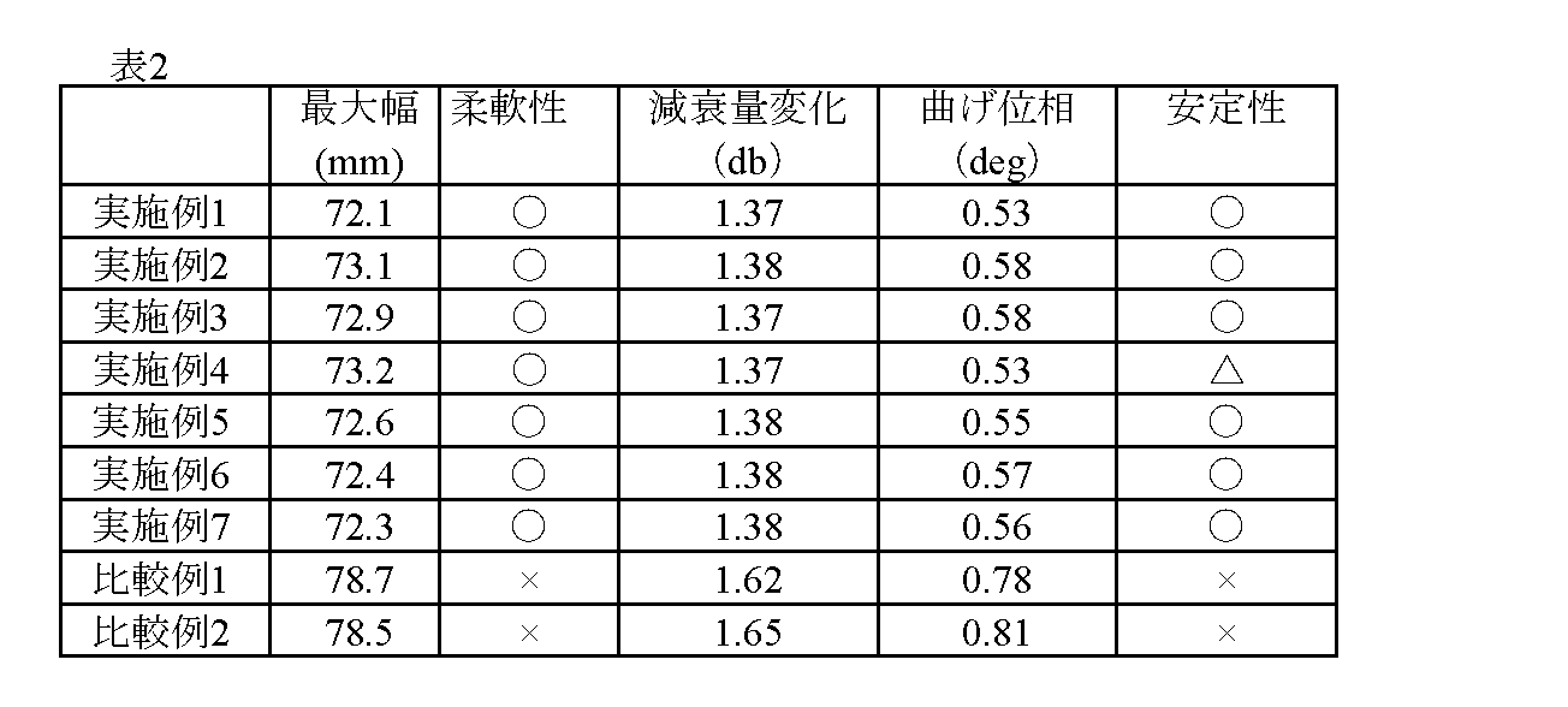
図3は柔軟性試験の態様を示す説明図である。柔軟性試験は、長さ500mmの同軸ケーブル10の両端を固定具31で固定し、重り32をつけない場合の最大幅Wと、50gの重り32を同軸ケーブル10の最下点につけた場合の最大幅Wを測定した。最大幅Wが小さいほど柔軟であるといえる。実施例1~7及び比較例1,2の同軸ケーブルについて試験し、その結果を表2示す。表2の結果より、実施例1~7は、柔軟であった。一方、比較例1は編組構造であり、柔軟性に乏しかった。
[Flexibility test]
FIG. 3 is an explanatory diagram showing an aspect of the flexibility test. In the flexibility test, both ends of a 500 mm long
[屈曲試験]
図4は、屈曲試験の態様を示す説明図である。屈曲試験は、長さ1000mmの同軸ケーブル10を、直径10cmの2つのロール42,42間に挟み、同軸ケーブル10の下方端部に荷重41を取り付け、ロール42と下方端部との間を振れ止め43,43で挟んだ。こうした態様にした後、ロール42の上方の同軸ケーブル10をロール42の円弧に沿って左右180°に20回/分の速度で50分間屈曲させた。
[Bending test]
FIG. 4 is an explanatory diagram showing an aspect of a bending test. In the bending test, a
実施例1~3及び比較例1,2の同軸ケーブルについて、試験前後の減衰量と曲げ位相を測定した。測定は、曲げ位相は、得られた同軸ケーブルを長さ700mmに切断し、コネクタを付けた後の同軸ケーブルを曲率半径50mmの円を形成するように曲げて、26.5GHzの周波数でネットワーク解析して得た。ネットワーク解析は、ネットワークアナライザ(株式会社KEYSIGHT製)を用い、測定ケーブルとコネクタはネットワークアナライザの附属のものを使用した。ネットワーク解析では、同軸ケーブル10に高周波正弦波信号を入射した場合の反射測定と伝送測定とで、信号の振幅と位相の変化を測定することができる。変化した振幅及び位相の測定結果は、ネットワークアナライザ内部で演算され、同軸ケーブル特性(減衰量、位相)を得ることができる。それらの結果を表2に示した。数値は、8GHzでの測定サンプル12個の平均値である。
The attenuation and bending phase of the coaxial cables of Examples 1 to 3 and Comparative Examples 1 and 2 were measured before and after the test. The bending phase was measured by cutting the obtained coaxial cable to a length of 700 mm, attaching a connector, bending the coaxial cable to form a circle with a radius of curvature of 50 mm, and conducting network analysis at a frequency of 26.5 GHz. I got it. For network analysis, a network analyzer (manufactured by KEYSIGHT Co., Ltd.) was used, and the measurement cable and connector that came with the network analyzer were used. In network analysis, changes in the amplitude and phase of a signal can be measured by reflection measurement and transmission measurement when a high frequency sine wave signal is input to the
10 同軸ケーブル
11 中心導体
12 絶縁体
12a 内環状部
12b 外環状部
12c 連結部
13 外部導体
13a 第1外部導体(金属樹脂テープ)
13b 第2外部導体(金属細線)
14 外被体
31 固定具
32 重り
41 荷重
42 ロール
43 振れ止め
W 最大幅
10
13b Second outer conductor (thin metal wire)
14
Claims (6)
Priority Applications (1)
| Application Number | Priority Date | Filing Date | Title |
|---|---|---|---|
| JP2019147915A JP7340384B2 (en) | 2019-08-09 | 2019-08-09 | Small diameter coaxial cable with excellent flexibility |
Applications Claiming Priority (1)
| Application Number | Priority Date | Filing Date | Title |
|---|---|---|---|
| JP2019147915A JP7340384B2 (en) | 2019-08-09 | 2019-08-09 | Small diameter coaxial cable with excellent flexibility |
Publications (2)
| Publication Number | Publication Date |
|---|---|
| JP2021028897A JP2021028897A (en) | 2021-02-25 |
| JP7340384B2 true JP7340384B2 (en) | 2023-09-07 |
Family
ID=74666969
Family Applications (1)
| Application Number | Title | Priority Date | Filing Date |
|---|---|---|---|
| JP2019147915A Active JP7340384B2 (en) | 2019-08-09 | 2019-08-09 | Small diameter coaxial cable with excellent flexibility |
Country Status (1)
| Country | Link |
|---|---|
| JP (1) | JP7340384B2 (en) |
Families Citing this family (1)
| Publication number | Priority date | Publication date | Assignee | Title |
|---|---|---|---|---|
| JP7140074B2 (en) * | 2019-08-27 | 2022-09-21 | 日立金属株式会社 | coaxial cable |
Citations (3)
| Publication number | Priority date | Publication date | Assignee | Title |
|---|---|---|---|---|
| JP2007265797A (en) | 2006-03-28 | 2007-10-11 | Sumitomo Electric Ind Ltd | Coaxial cable and its manufacturing method |
| JP2018113180A (en) | 2017-01-12 | 2018-07-19 | 日星電気株式会社 | coaxial cable |
| JP2019067549A (en) | 2017-09-29 | 2019-04-25 | 東京特殊電線株式会社 | Cable for high frequency communication |
Family Cites Families (1)
| Publication number | Priority date | Publication date | Assignee | Title |
|---|---|---|---|---|
| JP3013637B2 (en) * | 1992-12-28 | 2000-02-28 | 住友電気工業株式会社 | High frequency coaxial cable and method of manufacturing the same |
-
2019
- 2019-08-09 JP JP2019147915A patent/JP7340384B2/en active Active
Patent Citations (3)
| Publication number | Priority date | Publication date | Assignee | Title |
|---|---|---|---|---|
| JP2007265797A (en) | 2006-03-28 | 2007-10-11 | Sumitomo Electric Ind Ltd | Coaxial cable and its manufacturing method |
| JP2018113180A (en) | 2017-01-12 | 2018-07-19 | 日星電気株式会社 | coaxial cable |
| JP2019067549A (en) | 2017-09-29 | 2019-04-25 | 東京特殊電線株式会社 | Cable for high frequency communication |
Also Published As
| Publication number | Publication date |
|---|---|
| JP2021028897A (en) | 2021-02-25 |
Similar Documents
| Publication | Publication Date | Title |
|---|---|---|
| JP5421565B2 (en) | coaxial cable | |
| US10763012B2 (en) | Shielded cable | |
| US20110036613A1 (en) | Electronic wire and method of manufacturing the same | |
| JP5900275B2 (en) | Cable for multi-pair differential signal transmission | |
| JP3900864B2 (en) | 2-core parallel micro coaxial cable | |
| JP2008171778A (en) | Coaxial cable | |
| JP7340384B2 (en) | Small diameter coaxial cable with excellent flexibility | |
| JP5464080B2 (en) | Coaxial cable and multi-core coaxial cable | |
| WO2022059406A1 (en) | Coaxial cable | |
| JP2019067549A (en) | Cable for high frequency communication | |
| US20230154652A1 (en) | Coaxial cable | |
| JP7353039B2 (en) | Coaxial cable with excellent bending phase stability | |
| JP7474590B2 (en) | Multi-core communication cable | |
| WO2020004132A1 (en) | Coaxial cable | |
| JP2003031046A (en) | Two-core parallel extra-file coaxial cable with longitudinally added deposited tape | |
| WO2022130801A1 (en) | Multicore parallel cable and method for manufacturing same | |
| JP7412162B2 (en) | multicore communication cable | |
| WO2023058250A1 (en) | Coaxial cable | |
| JP2021028898A (en) | Small diameter coaxial cable excellent in flexibility | |
| US20210343451A1 (en) | Communication cable and wire harness | |
| JP2020021713A (en) | Multicore communication cable | |
| KR20210123976A (en) | Coaxial cable | |
| JP5874595B2 (en) | Differential signal transmission cable | |
| WO2022209876A1 (en) | Coaxial cable | |
| JP2021125327A (en) | Coaxial cable having good terminal workability |
Legal Events
| Date | Code | Title | Description |
|---|---|---|---|
| A621 | Written request for application examination |
Free format text: JAPANESE INTERMEDIATE CODE: A621 Effective date: 20220720 |
|
| A711 | Notification of change in applicant |
Free format text: JAPANESE INTERMEDIATE CODE: A712 Effective date: 20230509 |
|
| A977 | Report on retrieval |
Free format text: JAPANESE INTERMEDIATE CODE: A971007 Effective date: 20230515 |
|
| A131 | Notification of reasons for refusal |
Free format text: JAPANESE INTERMEDIATE CODE: A131 Effective date: 20230530 |
|
| A521 | Request for written amendment filed |
Free format text: JAPANESE INTERMEDIATE CODE: A523 Effective date: 20230719 |
|
| TRDD | Decision of grant or rejection written | ||
| A01 | Written decision to grant a patent or to grant a registration (utility model) |
Free format text: JAPANESE INTERMEDIATE CODE: A01 Effective date: 20230822 |
|
| A61 | First payment of annual fees (during grant procedure) |
Free format text: JAPANESE INTERMEDIATE CODE: A61 Effective date: 20230828 |
|
| R150 | Certificate of patent or registration of utility model |
Ref document number: 7340384 Country of ref document: JP Free format text: JAPANESE INTERMEDIATE CODE: R150 |