JP7338519B2 - battery pack - Google Patents
battery pack Download PDFInfo
- Publication number
- JP7338519B2 JP7338519B2 JP2020041903A JP2020041903A JP7338519B2 JP 7338519 B2 JP7338519 B2 JP 7338519B2 JP 2020041903 A JP2020041903 A JP 2020041903A JP 2020041903 A JP2020041903 A JP 2020041903A JP 7338519 B2 JP7338519 B2 JP 7338519B2
- Authority
- JP
- Japan
- Prior art keywords
- width direction
- vehicle
- vehicle width
- pair
- bead
- Prior art date
- Legal status (The legal status is an assumption and is not a legal conclusion. Google has not performed a legal analysis and makes no representation as to the accuracy of the status listed.)
- Active
Links
Images


Classifications
-
- H—ELECTRICITY
- H01—ELECTRIC ELEMENTS
- H01M—PROCESSES OR MEANS, e.g. BATTERIES, FOR THE DIRECT CONVERSION OF CHEMICAL ENERGY INTO ELECTRICAL ENERGY
- H01M50/00—Constructional details or processes of manufacture of the non-active parts of electrochemical cells other than fuel cells, e.g. hybrid cells
- H01M50/20—Mountings; Secondary casings or frames; Racks, modules or packs; Suspension devices; Shock absorbers; Transport or carrying devices; Holders
- H01M50/204—Racks, modules or packs for multiple batteries or multiple cells
- H01M50/207—Racks, modules or packs for multiple batteries or multiple cells characterised by their shape
-
- B—PERFORMING OPERATIONS; TRANSPORTING
- B60—VEHICLES IN GENERAL
- B60K—ARRANGEMENT OR MOUNTING OF PROPULSION UNITS OR OF TRANSMISSIONS IN VEHICLES; ARRANGEMENT OR MOUNTING OF PLURAL DIVERSE PRIME-MOVERS IN VEHICLES; AUXILIARY DRIVES FOR VEHICLES; INSTRUMENTATION OR DASHBOARDS FOR VEHICLES; ARRANGEMENTS IN CONNECTION WITH COOLING, AIR INTAKE, GAS EXHAUST OR FUEL SUPPLY OF PROPULSION UNITS IN VEHICLES
- B60K1/00—Arrangement or mounting of electrical propulsion units
- B60K1/04—Arrangement or mounting of electrical propulsion units of the electric storage means for propulsion
-
- B—PERFORMING OPERATIONS; TRANSPORTING
- B60—VEHICLES IN GENERAL
- B60L—PROPULSION OF ELECTRICALLY-PROPELLED VEHICLES; SUPPLYING ELECTRIC POWER FOR AUXILIARY EQUIPMENT OF ELECTRICALLY-PROPELLED VEHICLES; ELECTRODYNAMIC BRAKE SYSTEMS FOR VEHICLES IN GENERAL; MAGNETIC SUSPENSION OR LEVITATION FOR VEHICLES; MONITORING OPERATING VARIABLES OF ELECTRICALLY-PROPELLED VEHICLES; ELECTRIC SAFETY DEVICES FOR ELECTRICALLY-PROPELLED VEHICLES
- B60L50/00—Electric propulsion with power supplied within the vehicle
- B60L50/50—Electric propulsion with power supplied within the vehicle using propulsion power supplied by batteries or fuel cells
- B60L50/60—Electric propulsion with power supplied within the vehicle using propulsion power supplied by batteries or fuel cells using power supplied by batteries
- B60L50/64—Constructional details of batteries specially adapted for electric vehicles
-
- B—PERFORMING OPERATIONS; TRANSPORTING
- B62—LAND VEHICLES FOR TRAVELLING OTHERWISE THAN ON RAILS
- B62D—MOTOR VEHICLES; TRAILERS
- B62D25/00—Superstructure or monocoque structure sub-units; Parts or details thereof not otherwise provided for
- B62D25/20—Floors or bottom sub-units
-
- H—ELECTRICITY
- H01—ELECTRIC ELEMENTS
- H01M—PROCESSES OR MEANS, e.g. BATTERIES, FOR THE DIRECT CONVERSION OF CHEMICAL ENERGY INTO ELECTRICAL ENERGY
- H01M50/00—Constructional details or processes of manufacture of the non-active parts of electrochemical cells other than fuel cells, e.g. hybrid cells
- H01M50/20—Mountings; Secondary casings or frames; Racks, modules or packs; Suspension devices; Shock absorbers; Transport or carrying devices; Holders
- H01M50/218—Mountings; Secondary casings or frames; Racks, modules or packs; Suspension devices; Shock absorbers; Transport or carrying devices; Holders characterised by the material
- H01M50/22—Mountings; Secondary casings or frames; Racks, modules or packs; Suspension devices; Shock absorbers; Transport or carrying devices; Holders characterised by the material of the casings or racks
- H01M50/222—Inorganic material
- H01M50/224—Metals
-
- H—ELECTRICITY
- H01—ELECTRIC ELEMENTS
- H01M—PROCESSES OR MEANS, e.g. BATTERIES, FOR THE DIRECT CONVERSION OF CHEMICAL ENERGY INTO ELECTRICAL ENERGY
- H01M50/00—Constructional details or processes of manufacture of the non-active parts of electrochemical cells other than fuel cells, e.g. hybrid cells
- H01M50/20—Mountings; Secondary casings or frames; Racks, modules or packs; Suspension devices; Shock absorbers; Transport or carrying devices; Holders
- H01M50/233—Mountings; Secondary casings or frames; Racks, modules or packs; Suspension devices; Shock absorbers; Transport or carrying devices; Holders characterised by physical properties of casings or racks, e.g. dimensions
- H01M50/24—Mountings; Secondary casings or frames; Racks, modules or packs; Suspension devices; Shock absorbers; Transport or carrying devices; Holders characterised by physical properties of casings or racks, e.g. dimensions adapted for protecting batteries from their environment, e.g. from corrosion
-
- H—ELECTRICITY
- H01—ELECTRIC ELEMENTS
- H01M—PROCESSES OR MEANS, e.g. BATTERIES, FOR THE DIRECT CONVERSION OF CHEMICAL ENERGY INTO ELECTRICAL ENERGY
- H01M50/00—Constructional details or processes of manufacture of the non-active parts of electrochemical cells other than fuel cells, e.g. hybrid cells
- H01M50/20—Mountings; Secondary casings or frames; Racks, modules or packs; Suspension devices; Shock absorbers; Transport or carrying devices; Holders
- H01M50/244—Secondary casings; Racks; Suspension devices; Carrying devices; Holders characterised by their mounting method
-
- H—ELECTRICITY
- H01—ELECTRIC ELEMENTS
- H01M—PROCESSES OR MEANS, e.g. BATTERIES, FOR THE DIRECT CONVERSION OF CHEMICAL ENERGY INTO ELECTRICAL ENERGY
- H01M50/00—Constructional details or processes of manufacture of the non-active parts of electrochemical cells other than fuel cells, e.g. hybrid cells
- H01M50/20—Mountings; Secondary casings or frames; Racks, modules or packs; Suspension devices; Shock absorbers; Transport or carrying devices; Holders
- H01M50/249—Mountings; Secondary casings or frames; Racks, modules or packs; Suspension devices; Shock absorbers; Transport or carrying devices; Holders specially adapted for aircraft or vehicles, e.g. cars or trains
-
- H—ELECTRICITY
- H01—ELECTRIC ELEMENTS
- H01M—PROCESSES OR MEANS, e.g. BATTERIES, FOR THE DIRECT CONVERSION OF CHEMICAL ENERGY INTO ELECTRICAL ENERGY
- H01M50/00—Constructional details or processes of manufacture of the non-active parts of electrochemical cells other than fuel cells, e.g. hybrid cells
- H01M50/20—Mountings; Secondary casings or frames; Racks, modules or packs; Suspension devices; Shock absorbers; Transport or carrying devices; Holders
- H01M50/271—Lids or covers for the racks or secondary casings
- H01M50/273—Lids or covers for the racks or secondary casings characterised by the material
- H01M50/276—Inorganic material
-
- H—ELECTRICITY
- H01—ELECTRIC ELEMENTS
- H01M—PROCESSES OR MEANS, e.g. BATTERIES, FOR THE DIRECT CONVERSION OF CHEMICAL ENERGY INTO ELECTRICAL ENERGY
- H01M50/00—Constructional details or processes of manufacture of the non-active parts of electrochemical cells other than fuel cells, e.g. hybrid cells
- H01M50/20—Mountings; Secondary casings or frames; Racks, modules or packs; Suspension devices; Shock absorbers; Transport or carrying devices; Holders
- H01M50/298—Mountings; Secondary casings or frames; Racks, modules or packs; Suspension devices; Shock absorbers; Transport or carrying devices; Holders characterised by the wiring of battery packs
-
- B—PERFORMING OPERATIONS; TRANSPORTING
- B60—VEHICLES IN GENERAL
- B60K—ARRANGEMENT OR MOUNTING OF PROPULSION UNITS OR OF TRANSMISSIONS IN VEHICLES; ARRANGEMENT OR MOUNTING OF PLURAL DIVERSE PRIME-MOVERS IN VEHICLES; AUXILIARY DRIVES FOR VEHICLES; INSTRUMENTATION OR DASHBOARDS FOR VEHICLES; ARRANGEMENTS IN CONNECTION WITH COOLING, AIR INTAKE, GAS EXHAUST OR FUEL SUPPLY OF PROPULSION UNITS IN VEHICLES
- B60K1/00—Arrangement or mounting of electrical propulsion units
- B60K1/04—Arrangement or mounting of electrical propulsion units of the electric storage means for propulsion
- B60K2001/0405—Arrangement or mounting of electrical propulsion units of the electric storage means for propulsion characterised by their position
- B60K2001/0438—Arrangement under the floor
-
- H—ELECTRICITY
- H01—ELECTRIC ELEMENTS
- H01M—PROCESSES OR MEANS, e.g. BATTERIES, FOR THE DIRECT CONVERSION OF CHEMICAL ENERGY INTO ELECTRICAL ENERGY
- H01M2220/00—Batteries for particular applications
- H01M2220/20—Batteries in motive systems, e.g. vehicle, ship, plane
-
- Y—GENERAL TAGGING OF NEW TECHNOLOGICAL DEVELOPMENTS; GENERAL TAGGING OF CROSS-SECTIONAL TECHNOLOGIES SPANNING OVER SEVERAL SECTIONS OF THE IPC; TECHNICAL SUBJECTS COVERED BY FORMER USPC CROSS-REFERENCE ART COLLECTIONS [XRACs] AND DIGESTS
- Y02—TECHNOLOGIES OR APPLICATIONS FOR MITIGATION OR ADAPTATION AGAINST CLIMATE CHANGE
- Y02E—REDUCTION OF GREENHOUSE GAS [GHG] EMISSIONS, RELATED TO ENERGY GENERATION, TRANSMISSION OR DISTRIBUTION
- Y02E60/00—Enabling technologies; Technologies with a potential or indirect contribution to GHG emissions mitigation
- Y02E60/10—Energy storage using batteries
-
- Y—GENERAL TAGGING OF NEW TECHNOLOGICAL DEVELOPMENTS; GENERAL TAGGING OF CROSS-SECTIONAL TECHNOLOGIES SPANNING OVER SEVERAL SECTIONS OF THE IPC; TECHNICAL SUBJECTS COVERED BY FORMER USPC CROSS-REFERENCE ART COLLECTIONS [XRACs] AND DIGESTS
- Y02—TECHNOLOGIES OR APPLICATIONS FOR MITIGATION OR ADAPTATION AGAINST CLIMATE CHANGE
- Y02T—CLIMATE CHANGE MITIGATION TECHNOLOGIES RELATED TO TRANSPORTATION
- Y02T10/00—Road transport of goods or passengers
- Y02T10/60—Other road transportation technologies with climate change mitigation effect
- Y02T10/70—Energy storage systems for electromobility, e.g. batteries
Description
本発明は、バッテリパックに関する。 The present invention relates to battery packs.
自動車等の車両にあっては、走行用のモータに電力を供給するバッテリをフロアパネルの下面側に搭載することがある。従来のこの種のバッテリパックとして特許文献1に記載されたものが知られている。特許文献1に記載のバッテリパックにおいて、バッテリケースの車両幅方向中央の上面には、上方に突出する凸部が形成されている。特許文献1に記載のバッテリパックは、バッテリケースの上面の凸部を補強用のビードとして機能させることにより、バッテリケースの剛性を向上させることができる。
In a vehicle such as an automobile, a battery for supplying electric power to a driving motor is sometimes mounted on the lower surface side of the floor panel. As a conventional battery pack of this type, the one described in
ここで、車体のフロアパネルの下面には、後輪のブレーキに作動油を供給するブレーキ配管等が配置されることがある。したがって、フロアパネルの下面側にブレーキ配管の設置スペースを確保した上で、バッテリパックの形状や設置位置を検討することが重要となる。 In some cases, a brake pipe or the like for supplying hydraulic oil to the brakes of the rear wheels is arranged on the lower surface of the floor panel of the vehicle body. Therefore, it is important to consider the shape and installation position of the battery pack after securing the installation space for the brake piping on the lower surface side of the floor panel.
しかしながら、特許文献1に記載の従来の技術にあっては、ブレーキ配管等の配管をフロアパネルとバッテリパックとの間に設置することを考慮していないので、配管を設置するためにバッテリパックの搭載位置がより下方に変更され、これにより車両の走行に必要な地面から車両下部までの高さ(最低地上高)を確保できなくなるおそれがあった。
However, in the conventional technique described in
また、特許文献1に記載の技術において、バッテリケースの上面の凸部の突出量を小さくして配管の設置スペースを確保するようにした場合、バッテリケースの剛性が低下するおそれがあった。
In addition, in the technique described in
本発明は、上記のような事情に着目してなされたものであり、車両の最低地上高を確保でき、かつ、バッテリケースの剛性低下を抑制できるバッテリパックを提供することを目的とするものである。 SUMMARY OF THE INVENTION It is an object of the present invention to provide a battery pack capable of securing a minimum ground clearance of a vehicle and suppressing deterioration of the rigidity of the battery case. be.
本発明は、複数のバッテリモジュールと、車体のフロアパネルの下方に配置され、前記バッテリモジュールを収納するバッテリケースと、を備え、前記バッテリケースは前記バッテリモジュールを上方から覆うアッパケースを有し、車両前後方向に延びる配管が前記フロアパネルと前記アッパケースとで挟まれるように配索され、前記アッパケースの上面に前記配管を保持するクランプ部材が設けられたバッテリパックであって、前記アッパケースの上面に、上方に突出し、かつ、車両前後方向に延びる主ビードが設けられ、前記主ビードは、その車両前方側の部位を構成する第1ビード部と、前記第1ビード部の車両後方側に配置された第2ビード部と、前記第1ビード部と前記第2ビード部とを分断するように下方に凹む凹部と、を有し、前記第1ビード部の後端部に、車両後方に延びる一対の延長部を設け、一対の前記延長部の間に前記第2ビード部の前端部が配置され、前記配管は、前記バッテリケースの上方であって、前記配管の少なくとも一部が前記第1ビード部と一対の前記延長部と前記第2ビード部とで囲まれるように配置されていることを特徴とする。 The present invention includes a plurality of battery modules, and a battery case disposed below a floor panel of a vehicle body and housing the battery modules, the battery case having an upper case covering the battery modules from above, A battery pack in which a pipe extending in a longitudinal direction of a vehicle is routed so as to be sandwiched between the floor panel and the upper case, and a clamp member for holding the pipe is provided on an upper surface of the upper case, the upper case comprising: A main bead projecting upward and extending in the vehicle front-rear direction is provided on the upper surface of the and a concave portion recessed downward so as to divide the first bead portion and the second bead portion. a pair of extension portions extending to the above, the front end portion of the second bead portion is disposed between the pair of extension portions, the pipe is above the battery case, and at least a portion of the pipe extends from the It is characterized by being surrounded by the first bead portion, the pair of extension portions, and the second bead portion.
このように上記の本発明によれば、車両の最低地上高を確保でき、かつ、バッテリケースの剛性低下を抑制できるバッテリパックを提供することができる。 As described above, according to the present invention, it is possible to provide a battery pack that can secure the minimum ground clearance of the vehicle and can suppress the deterioration of the rigidity of the battery case.
本発明の一実施の形態に係るバッテリパックは、複数のバッテリモジュールと、車体のフロアパネルの下方に配置され、バッテリモジュールを収納するバッテリケースと、を備え、バッテリケースはバッテリモジュールを上方から覆うアッパケースを有し、車両前後方向に延びる配管がフロアパネルとアッパケースとで挟まれるように配索され、アッパケースの上面に配管を保持するクランプ部材が設けられたバッテリパックであって、アッパケースの上面に、上方に突出し、かつ、車両前後方向に延びる主ビードが設けられ、主ビードは、その車両前方側の部位を構成する第1ビード部と、第1ビード部の車両後方側に配置された第2ビード部と、第1ビード部と第2ビード部とを分断するように下方に凹む凹部と、を有し、第1ビード部の後端部に、車両後方に延びる一対の延長部を設け、一対の延長部の間に第2ビード部の前端部が配置され、配管は、バッテリケースの上方であって、配管の少なくとも一部が第1ビード部と一対の延長部と第2ビード部とで囲まれるように配置されていることを特徴とする。これにより、本発明の一実施の形態に係るバッテリパックは、車両の最低地上高を確保でき、かつ、バッテリケースの剛性低下を抑制できる。 A battery pack according to an embodiment of the present invention includes a plurality of battery modules and a battery case that is arranged below a floor panel of a vehicle body and stores the battery modules. The battery case covers the battery modules from above. A battery pack having an upper case, wherein pipes extending in the longitudinal direction of the vehicle are routed so as to be sandwiched between the floor panel and the upper case, and a clamp member for holding the pipes is provided on the upper surface of the upper case, the upper case comprising: A main bead projecting upward and extending in the vehicle front-rear direction is provided on the upper surface of the case. A pair of grooves extending rearward of the vehicle are provided at the rear end of the first bead portion, and have a second bead portion disposed thereon and a concave portion recessed downward so as to divide the first bead portion and the second bead portion. An extension is provided, the front end of the second bead is disposed between the pair of extensions, the pipe is above the battery case, and at least a portion of the pipe extends between the first bead and the pair of extensions. It is characterized by being arranged so as to be surrounded by the second bead portion. As a result, the battery pack according to the embodiment of the present invention can ensure the minimum ground clearance of the vehicle, and can suppress a decrease in rigidity of the battery case.
以下、本発明の実施例に係るバッテリパックについて、図面を用いて説明する。図1から図6において、上下前後左右方向は、車両に設置された状態のバッテリパックの上下前後左右方向とし、車両の前後方向に対して直交する方向が左右方向、バッテリパックの高さ方向が上下方向である。 A battery pack according to an embodiment of the present invention will be described below with reference to the drawings. 1 to 6, the vertical, front, rear, left, and right directions are the vertical, front, rear, left, and right directions of the battery pack installed in the vehicle, the horizontal direction is the direction perpendicular to the front-rear direction of the vehicle, and the height direction of the battery pack is the vertical direction. Up-down direction.
図1から図6は、本発明の一実施例に係るバッテリパックを示す図である。 1 to 6 are diagrams showing a battery pack according to one embodiment of the present invention.
まず、構成を説明する。図1において、車両1は、車体2を備えている。車体2は、その下部にフロアパネル2Aを有している。フロアパネル2Aの後部には凹部2Bが設けられており、この凹部2Bは、下方に窪んでいる。凹部2Bには図示しないスペアタイヤが収容されている。フロアパネル2Aには、車両前後方向に延びる左右で一対のサイドメンバ11が設けられている。サイドメンバ11には、車両幅方向に延びるクロスメンバ13、14が接続されている。
First, the configuration will be explained. In FIG. 1 , a
フロアパネル2Aの下側にはバッテリパック20が設けられている。バッテリパック20は車両1の図示しないモータに電力を供給する。バッテリパック20は、一対のサイドメンバ11の間に配置されている。クロスメンバ13は、バッテリパック20の前端部の上部の近傍を車両幅方向に横切るように配置されている。クロスメンバ14は、バッテリパック20の車両前後方向の中間部の後方寄りの部位の上部を車両幅方向に横切るように配置されている。なお、図1は、バッテリパック20の上部においてフロアパネル2Aの一部を透過してバッテリパック20を見た状態を表わしている。
A
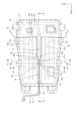
図3において、バッテリパック20は、複数のバッテリモジュール61と、複数のバッテリモジュール61を収容するバッテリケース21と、を有している。バッテリケース21は、平面視において全体として四角形に形成されている。
In FIG. 3 , the
バッテリケース21はロアケース40とアッパケース30とからなる。アッパケース30はバッテリケース21の上部を構成しており、バッテリモジュール61を上方から覆っている。ロアケース40はバッテリケース21の下部を構成しており、バッテリモジュール61を保持している。ロアケース40は、バッテリモジュール61の下面および側面を覆っている。
図1、図2において、フロアパネル2Aの車両幅方向の中央部の上面には、ブレーキ用の配管51、52が配置されている。配管51、52がフロアパネル2Aとアッパケース30とで挟まれるように、車両前後方向に延びている。アッパケース30の上面にはクランプ部材53が設けられており、クランプ部材53は配管51、52を保持している。
1 and 2,
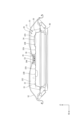
図2において、アッパケース30の上面には、車両前後方向に延びる主ビード35が設けられている。主ビード35は、アッパケース30の基準面32から上方に突出している。ここで、基準面32とは、アッパケース30の上面における何らの凸形状も形成されていない平坦な部分の面である。
In FIG. 2, the upper surface of the
主ビード35は、その車両前方側の部位を構成する第1ビード部36と、第1ビード部36の車両後方側に配置された第2ビード部37と、第1ビード部36と第2ビード部37とを分断するように下方に凹む凹部35Aと、を有している。
The
第1ビード部36の後端部には、車両後方に延びる一対の延長部36Bを設けられている。一対の延長部36Bの間には第2ビード部37の前端部が配置されている。
A pair of
配管51、52の一部は凹部35Aに配置されている。したがって、凹部35Aにおいて、配管51、52の一部は、第1ビード部36と一対の延長部36Bと第2ビード部37とで囲まれている。
A part of the
図2、図4において、第1ビード部36は、その後端部に車両幅方向の寸法が拡張された拡張部36Aを有している。拡張部36Aの車両幅方向の両端部には、一対の延長部36Bが接続されている。このように、一対の延長部36Bは、第1ビード部36の後端部に対して直接設けられるのではなく、車両幅方向の寸法が拡張された拡張部36Aを介して設けられている。
2 and 4, the
図2、図5において、一対の延長部36Bは、第2ビード部37の前端部37Aと車両幅方向で対向するように形成されている。また、一対の延長部36Bと第2ビード部37の前端部との間に、凹部35Aからアッパケース30の上面に連通する溝状の水排出路35Bが設けられている。
2 and 5, the pair of
図2において、アッパケース30の上面であって、一対の延長部36Bの車両幅方向の外側には、上方に突出し、かつ、車両前後方向に延びる一対の副ビード32Aが設けられている。一対の延長部36Bの車両幅方向の寸法は、第1ビード部36の車両幅方向の寸法より小さく設定されている。一対の延長部36Bは、車両幅方向で一対の副ビード32Aと第2ビード部37の前端部37Aとの間に配置されている。
2, a pair of sub-beads 32A that protrude upward and extend in the vehicle front-rear direction are provided on the upper surface of the
図2において、アッパケース30の車両幅方向の寸法は、車両前後方向の位置によって異なっている。詳しくは、アッパケース30の車両幅方向の寸法は、アッパケース30の後端部において最も大きく、アッパケース30の前端部において最も小さい。また、アッパケース30における車両幅方向の寸法が最も大きい部位(後端部)よりも小さい部位に、一対の延長部36Bが設けられている。
In FIG. 2, the dimension of the
図3において、アッパケース30の上面には、複数対の副ビード32A、32B、32Cが設けられている。隣り合う副ビード32C、32Bの間の距離をL1とし、隣り合う副ビード32A、32Bの間の距離をL2とし、副ビード32Aと延長部36Bとの車両幅方向の距離をL3としたとき、隣り合う副ビードの間の距離L1、L2は、車両幅方向の外側から内側に近づくほど小さくなっている。また、延長部36Bに最も近い副ビード32Aと延長部36Bとの車両幅方向の距離L3は、隣り合う副ビードの間の距離L1、L2のいずれよりも小さくされている。
In FIG. 3 , the upper surface of the
図2、図6において、アッパケース30の後端であって第2ビード部37の車両後方の位置には、車両上方に突出する凸部33が設けられている。凸部33は、車両幅方向に延びている。
2 and 6, a
図2、図6において、第2ビード部37の後端部は凸部33に接続されている。第2ビード部37の後端部は湾曲部37Bを有しており、湾曲部37Bは、車両前後方向から車両幅方向に向きを変えるように湾曲している。
2 and 6, the rear end portion of the
湾曲部37Bはその車両幅方向端部で凸部33と接している。湾曲部37Bが凸部33と接する当接部37Cは、車両幅方向で、一対の延長部36Bの車両幅方向の内側の部位36Cよりも外側に位置している。
The
図2において、バッテリケース21の車両幅方向端部には、バッテリケース21を車両に取り付けるための車体マウント部27が設けられている。また、車体マウント部27は、一対の延長部36Bと車両幅方向で対向している。言い換えれば、車体マウント部27は、車両幅方向から見た場合に延長部36Bと重なる位置に設けられている。
In FIG. 2, a vehicle
図2、図4において、アッパケース30の上面には、車両上方に突出する台座部34が設けられている。この台座部34には、電装部品としての図示しないサービスプラグが設けられている。サービスプラグは、図示しないプラグを引き抜く遮断操作を行うことにより通電を遮断する遮断装置である。
2 and 4, the upper surface of the
台座部34は、延長部36Bと車両幅方向で対向して配置されている。言い換えれば、台座部34は、車両幅方向から見た場合に延長部36Bと重なる位置に設けられている。
The
以上説明したように、本実施例のバッテリパック20において、アッパケース30の上面に、上方に突出し、かつ、車両前後方向に延びる主ビード35が設けられ、主ビード35は、その車両前方側の部位を構成する第1ビード部36と、第1ビード部36の車両後方側に配置された第2ビード部37と、第1ビード部36と第2ビード部37とを分断するように下方に凹む凹部35Aと、を有している。
As described above, in the
また、第1ビード部36の後端部に、車両後方に延びる一対の延長部36Bを設け、一対の延長部36Bの間に第2ビード部37の前端部37Aが配置されている。
A pair of
そして、配管51、52は、バッテリケース21の上方であって、配管51、52の少なくとも一部が第1ビード部36と一対の延長部36Bと第2ビード部37とで囲まれるように配置されている。
The
この構成により、第1ビード部36と第2ビード部37の間に設けられた凹部35Aの車両幅方向の両外側を一対の延長部36Bによって補強でき、第1ビード部36と第2ビード部37とを延長部36Bによって構造的に結合することができる。また、一対の延長部36Bは、第1ビード部36および第2ビード部37よりも車両幅方向外側に位置するので、アッパケース30の車両幅方向の捻れ振動の発生を抑制できる。このため、凹部35Aを設けたことによるアッパケース30の剛性低下を抑制できる。
With this configuration, both outer sides in the vehicle width direction of the recessed
また、配管51、52を保持するクランプ部材53を、アッパケース30の上面の低い部位である凹部35Aに配置したので、車両1の最低地上高を確保することができる。
Further, since the
この結果、車両1の最低地上高を確保でき、かつ、バッテリケース21の剛性低下を抑制できる。
As a result, the minimum ground clearance of the
本実施例のバッテリパック20において、第1ビード部36は、その後端部に車両幅方向の寸法が拡張された拡張部36Aを有している。また、拡張部36Aの車両幅方向の両端部に一対の延長部36Bが接続されている。
In the
この構成により、第1ビード部36の後端部に直接一対の延長部36Bを設ける場合と比較して、一対の延長部36Bの相互の距離を拡大でき、アッパケース30の広い範囲で剛性を向上でき振動を抑制できる。
With this configuration, the distance between the pair of
本実施例のバッテリパック20において、一対の延長部36Bは、第2ビード部37の前端部37Aと車両幅方向で対向するように形成されている。また、一対の延長部36Bと第2ビード部37の前端部37Aとの間に、凹部35Aからアッパケース30の上面に連通する溝状の水排出路35Bが設けられている。
In the
この構成により、第1ビード部36と第2ビード部37とを一対の延長部36Bによって構造的に接続できるので、アッパケース30の剛性をより向上でき、アッパケース30の振動を抑制できる。
With this configuration, the
一対の延長部36Bと第2ビード部37との間に形成された水排出路35Bにより、凹部35Aに溜まった水をアッパケース30の上面に排出することができる。このため、凹部35Aに水が溜まることを防止でき、水によるアッパケース30の腐食を防止できる。
A
本実施例のバッテリパック20において、アッパケース30の上面であって、一対の延長部36Bの車両幅方向の外側に、上方に突出し、かつ、車両前後方向に延びる一対の副ビード32Aが設けられている。一対の延長部36Bの車両幅方向の寸法は、第1ビード部36の車両幅方向の寸法より小さく設定されている。一対の延長部36Bは、車両幅方向で一対の副ビード32Aと第2ビード部37の前端部37Aとの間に配置されている。
In the
この構成により、一対の延長部36Bの車両幅方向の寸法は、第1ビード部36の車両幅方向の寸法より小さく設定されているので、一対の副ビード32Aを一対の延長部36Bに近づけて配置することができ、第1ビード部36および第2ビード部37にも一対の副ビード32Aを近づけて配置できる。したがって、第1ビード部36、一対の延長部36B、第2ビード部37および一対の副ビード32Aを互いに近づけて配置でき、アッパケース30の剛性を向上させることができる。
With this configuration, the dimension of the pair of
また、幅寸法が小さい一対の延長部36Bが一対の副ビード32Aと第2ビード部37の前端部37Aとの間に配置されるので、アッパケース30の上面の面積を減らすことができ、アッパケース30の剛性を向上させ、振動を抑制できる。
In addition, since the pair of
本実施例のバッテリパック20において、アッパケース30の車両幅方向の寸法は、車両前後方向の位置によって異なっている。アッパケース30における車両幅方向の寸法が最も大きい部位よりも小さい部位に、一対の延長部36Bが設けられている。
In the
この構成により、一対の延長部36Bが設けられている部位において、一対の延長部36Bとアッパケース30の車両幅方向端部との距離は、車両幅方向の寸法が最も大きい部位よりも短くなる。このため、アッパケース30の剛性を向上させることができ、アッパケース30の振動を防止できる。
With this configuration, the distance between the pair of
本実施例のバッテリパック20において、アッパケース30の上面に、複数対の副ビード32A、32B、32Cが設けられている。隣り合う副ビードの間の距離L1、L2が、車両幅方向の外側から内側に近づくほど小さくなっている。延長部36Bに最も近い副ビード32Aと延長部36Bとの車両幅方向の距離L3は、隣り合う副ビードの間の距離L1、L2のいずれよりも小さくされている。
In the
この構成により、アッパケース30の車両幅方向の内側ほど、副ビード32A、32B、32Cの間の距離が小さくなるので、アッパケース30の車両幅方向の内側ほど剛性を向上させることができる。
With this configuration, the distance between the sub-beads 32A, 32B, and 32C becomes smaller toward the inner side of the
本実施例のバッテリパック20において、アッパケース30の後端であって第2ビード部37の車両後方の位置に、車両上方に突出し、かつ、車両幅方向に延びる凸部33が設けられている。第2ビード部37の後端部が凸部33に接続されている。第2ビード部37の後端部は、車両前後方向から車両幅方向に向きを変えるように湾曲する湾曲部37Bを有している。
In the
この構成により、上方に突出することで剛性が高められた凸部33に第2ビード部37を接続しているので、アッパケース30の剛性をさらに向上させることができ、アッパケース30の振動を抑制できる。
With this configuration, the
凹部35Aから水排出路35Bを通して後方に排出された水を、凸部33と湾曲部37Bとによって車両幅方向の外側に向かうように案内でき、水が再び凹部35Aに戻ることを抑制できる。
The
アッパケース30の後端に凸部33が設けられていることにより、主ビード35の車両前後方向の長さを短くすることができ、主ビード35の剛性を高めることができる。このため、アッパケース30の剛性を向上させることができ、アッパケース30の振動を抑制できる。
Since the
本実施例のバッテリパック20において、湾曲部37Bが凸部33と接する当接部37Cは、車両幅方向で、一対の延長部36Bの車両幅方向の内側の部位36Cよりも外側に位置している。
In the
この構成により、湾曲部37Bにおける凸部33との当接部37Cの位置が、一対の延長部36Bの内側の部位36Cよりも車両幅方向で外側に配置されているので、凹部35Aから水排出路35Bを通して後方に排出された水を、湾曲部37Bを通って車両幅方向の外側に向かうように案内して、水が再び凹部35Aに戻ることをより抑制できる。また、延長部36Bと第2ビード部37との距離を短くでき、かつ、凸部33と湾曲部37Bとの接合面積を拡大して凸部33と第2ビード部37とをより強固に結合でき、アッパケース30の剛性をより向上させることができる。
With this configuration, the position of the
本実施例のバッテリパック20において、バッテリケース21の車両幅方向端部に、バッテリケース21を車両に取り付けるための車体マウント部27が設けられている。車体マウント部27は、一対の延長部36Bと車両幅方向で対向している。
In the
この構成により、車体マウント部27が一対の延長部36Bに車両幅方向で対向して重なるように配置されているので、バッテリケース21における車体マウント部27材が配置された部位は、剛性が高くなる一方で車体の振動によるバッテリケース21の振動の起点となる部位である。このマウント部材に対して最も近い位置に延長部36Bが設けられているので、バッテリケース21の振動を抑制できる。
With this configuration, the vehicle
本実施例のバッテリパック20において、アッパケース30の上面に、電装部品を取り付けられ、車両上方に突出する台座部34が設けられている。台座部34は、延長部36Bと車両幅方向で対向している。
In the
この構成により、アッパケース30における車両幅方向の端部と延長部36Bとの間の平坦な部分の面積を少なくでき、アッパケース30の剛性を向上させることができる。
With this configuration, the area of the flat portion between the end portion in the vehicle width direction of the
台座部34は、取り付けられた電装部品を支持するための剛性を有しているので、その上面に台座部34を設けることによりアッパケース30の剛性を向上させることができる。
Since the
本発明の実施例を開示したが、当業者によっては本発明の範囲を逸脱することなく変更が加えられうることは明白である。すべてのこのような修正および等価物が次の請求項に含まれることが意図されている。 Although embodiments of the present invention have been disclosed, it will be apparent that modifications may be made by those skilled in the art without departing from the scope of the invention. All such modifications and equivalents are intended to be included in the following claims.
1...車両、2...車体、2A...フロアパネル、20...バッテリパック、21...バッテリケース、27...車体マウント部、30...アッパケース、32A,32B,32C...副ビード、33...凸部、34...台座部、35...主ビード、35A...凹部、35B...水排出路、36...第1ビード部、36A...拡張部、36B...延長部、36C...部位、37...第2ビード部、37A...前端部、37B...湾曲部、37C...当接部、51,52...配管、53...クランプ部材、61...バッテリモジュール、L1,L2...距離
DESCRIPTION OF
Claims (10)
車体のフロアパネルの下方に配置され、前記バッテリモジュールを収納するバッテリケースと、を備え、
前記バッテリケースは前記バッテリモジュールを上方から覆うアッパケースを有し、
車両前後方向に延びる配管が前記フロアパネルと前記アッパケースとで挟まれるように配索され、
前記アッパケースの上面に前記配管を保持するクランプ部材が設けられたバッテリパックであって、
前記アッパケースの上面に、上方に突出し、かつ、車両前後方向に延びる主ビードが設けられ、
前記主ビードは、その車両前方側の部位を構成する第1ビード部と、前記第1ビード部の車両後方側に配置された第2ビード部と、前記第1ビード部と前記第2ビード部とを分断するように下方に凹む凹部と、を有し、
前記第1ビード部の後端部に、車両後方に延びる一対の延長部を設け、一対の前記延長部の間に前記第2ビード部の前端部が配置され、
前記配管は、前記バッテリケースの上方であって、前記配管の少なくとも一部が前記第1ビード部と一対の前記延長部と前記第2ビード部とで囲まれるように配置されていることを特徴とするバッテリパック。 a plurality of battery modules;
a battery case disposed below a floor panel of the vehicle body and housing the battery module,
The battery case has an upper case covering the battery module from above,
a pipe extending in the longitudinal direction of the vehicle is routed so as to be sandwiched between the floor panel and the upper case;
A battery pack provided with a clamp member for holding the pipe on the upper surface of the upper case,
A main bead projecting upward and extending in the vehicle front-rear direction is provided on the upper surface of the upper case,
The main bead includes a first bead portion forming a portion on the vehicle front side, a second bead portion arranged on the vehicle rear side of the first bead portion, and the first bead portion and the second bead portion. and a recess recessed downward so as to divide the
A pair of extension portions extending rearward of the vehicle is provided at the rear end portion of the first bead portion, and the front end portion of the second bead portion is disposed between the pair of extension portions,
The pipe is arranged above the battery case so that at least part of the pipe is surrounded by the first bead portion, the pair of extension portions, and the second bead portion. battery pack.
前記拡張部の車両幅方向の両端部に一対の前記延長部が接続されていることを特徴とする請求項1に記載のバッテリパック。 The first bead portion has, at its rear end portion, an enlarged portion with an enlarged dimension in the vehicle width direction,
2. The battery pack according to claim 1, wherein the pair of extension portions are connected to both ends of the extension portion in the vehicle width direction.
一対の前記延長部と前記第2ビード部の前端部との間に、前記凹部から前記アッパケースの上面に連通する溝状の水排出路が設けられていることを特徴とする請求項1または請求項2に記載のバッテリパック。 The pair of extension portions are formed to face the front end portion of the second bead portion in the vehicle width direction,
2. A groove-shaped water discharge passage communicating from the recess to the upper surface of the upper case is provided between the pair of extension portions and the front end portion of the second bead portion. The battery pack according to claim 2.
一対の前記延長部の車両幅方向の寸法は、前記第1ビード部の車両幅方向の寸法より小さく設定され、
一対の前記延長部は、車両幅方向で一対の前記副ビードと前記第2ビード部の前端部との間に配置されていることを特徴とする請求項1から請求項3の何れか1項に記載のバッテリパック。 A pair of sub beads that protrude upward and extend in the vehicle front-rear direction are provided on the upper surface of the upper case and on the outer side of the pair of extension portions in the vehicle width direction,
The dimension of the pair of extension portions in the vehicle width direction is set smaller than the dimension of the first bead portion in the vehicle width direction,
4. The pair of extension portions is arranged between the pair of sub beads and the front end portion of the second bead portion in the vehicle width direction. battery pack described in .
前記アッパケースにおける車両幅方向の寸法が最も大きい部位よりも小さい部位に、一対の前記延長部が設けられていることを特徴とする請求項1から請求項4の何れか1項に記載のバッテリパック。 The dimension of the upper case in the vehicle width direction varies depending on the position in the vehicle front-rear direction,
5. The battery according to any one of claims 1 to 4, wherein the pair of extension portions are provided at a portion of the upper case that is smaller than a portion having the largest dimension in the vehicle width direction. pack.
隣り合う前記副ビードの間の距離が、車両幅方向の外側から内側に近づくほど小さくなり、
前記延長部に最も近い前記副ビードと前記延長部との車両幅方向の距離は、隣り合う前記副ビードの間の距離のいずれよりも小さいことを特徴とする請求項4に記載のバッテリパック。 A plurality of pairs of the sub-beads are provided on the upper surface of the upper case,
The distance between the adjacent sub-beads becomes smaller from the outside to the inside in the vehicle width direction,
5. The battery pack according to claim 4, wherein a distance in the vehicle width direction between the sub-bead closest to the extension and the extension is smaller than any distance between adjacent sub-beads.
前記第2ビード部の後端部が前記凸部に接続され、
前記第2ビード部の後端部は、車両前後方向から車両幅方向に向きを変えるように湾曲する湾曲部を有することを特徴とする請求項1から請求項6の何れか1項に記載のバッテリパック。 A protrusion projecting upward from the vehicle and extending in the vehicle width direction is provided at a rear end of the upper case and at a vehicle rear position of the second bead portion,
A rear end portion of the second bead portion is connected to the convex portion,
The rear end portion of the second bead portion has a curved portion that curves so as to change direction from the vehicle front-rear direction to the vehicle width direction. battery pack.
前記車体マウント部は、一対の前記延長部と車両幅方向で対向していること特徴とする請求項1から請求項8の何れか1項に記載のバッテリパック。 a vehicle body mounting portion for attaching the battery case to the vehicle is provided at a vehicle width direction end portion of the battery case;
The battery pack according to any one of claims 1 to 8, wherein the vehicle body mount portion faces the pair of extension portions in the vehicle width direction.
前記台座部は、前記延長部と車両幅方向で対向していることを特徴とする請求項1から請求項9の何れか1項に記載のバッテリパック。 A pedestal is provided on the upper surface of the upper case to which electrical components are attached and which protrudes upward from the vehicle,
The battery pack according to any one of claims 1 to 9, wherein the pedestal faces the extension in the vehicle width direction.
Priority Applications (2)
| Application Number | Priority Date | Filing Date | Title |
|---|---|---|---|
| JP2020041903A JP7338519B2 (en) | 2020-03-11 | 2020-03-11 | battery pack |
| DE102021105147.9A DE102021105147A1 (en) | 2020-03-11 | 2021-03-03 | BATTERY PACK |
Applications Claiming Priority (1)
| Application Number | Priority Date | Filing Date | Title |
|---|---|---|---|
| JP2020041903A JP7338519B2 (en) | 2020-03-11 | 2020-03-11 | battery pack |
Publications (3)
| Publication Number | Publication Date |
|---|---|
| JP2021142832A JP2021142832A (en) | 2021-09-24 |
| JP2021142832A5 JP2021142832A5 (en) | 2023-03-03 |
| JP7338519B2 true JP7338519B2 (en) | 2023-09-05 |
Family
ID=77457444
Family Applications (1)
| Application Number | Title | Priority Date | Filing Date |
|---|---|---|---|
| JP2020041903A Active JP7338519B2 (en) | 2020-03-11 | 2020-03-11 | battery pack |
Country Status (2)
| Country | Link |
|---|---|
| JP (1) | JP7338519B2 (en) |
| DE (1) | DE102021105147A1 (en) |
Citations (1)
| Publication number | Priority date | Publication date | Assignee | Title |
|---|---|---|---|---|
| JP2000344026A (en) | 1999-06-02 | 2000-12-12 | Nissan Motor Co Ltd | Wire and tubular part laying structure of electric automobile |
Family Cites Families (1)
| Publication number | Priority date | Publication date | Assignee | Title |
|---|---|---|---|---|
| JP6996352B2 (en) | 2018-03-06 | 2022-01-17 | トヨタ自動車株式会社 | Vehicle lower body structure |
-
2020
- 2020-03-11 JP JP2020041903A patent/JP7338519B2/en active Active
-
2021
- 2021-03-03 DE DE102021105147.9A patent/DE102021105147A1/en active Pending
Patent Citations (1)
| Publication number | Priority date | Publication date | Assignee | Title |
|---|---|---|---|---|
| JP2000344026A (en) | 1999-06-02 | 2000-12-12 | Nissan Motor Co Ltd | Wire and tubular part laying structure of electric automobile |
Also Published As
| Publication number | Publication date |
|---|---|
| DE102021105147A1 (en) | 2021-09-16 |
| JP2021142832A (en) | 2021-09-24 |
Similar Documents
| Publication | Publication Date | Title |
|---|---|---|
| US9415808B2 (en) | Vehicle front section structure | |
| EP1982903B1 (en) | Vehicle floor structure | |
| JP4844065B2 (en) | Body structure | |
| JP4913348B2 (en) | Body floor structure | |
| JP5211659B2 (en) | Canister mounting structure | |
| JP2019001356A (en) | Vehicle front structure | |
| WO2011030400A1 (en) | Structure for vehicle lower portion | |
| JP5984052B2 (en) | Battery pack positioning pin bracket | |
| JP6452044B2 (en) | Rear body structure of automobile | |
| JP7338519B2 (en) | battery pack | |
| JP7444039B2 (en) | electric vehicle | |
| JP2017202764A (en) | Electric leakage prevention structure for battery | |
| JP5999506B2 (en) | Car body holding structure of resin front end | |
| CN111952690B (en) | Cooling structure of battery unit for vehicle | |
| KR101795396B1 (en) | Reinforcement structure of battery mounting part for electric vehicle | |
| CN110155182B (en) | Vehicle body structure | |
| JP2012041025A (en) | Structure for mounting battery | |
| JP2019001279A (en) | Ground guard attachment structure | |
| JP6609978B2 (en) | Wiring fixing structure of vehicle | |
| KR100764504B1 (en) | A mounting structure of rear frame in a bus | |
| CN106427534B (en) | A kind of water tank cross beam support construction and automobile | |
| CN112046261B (en) | Vehicle and drive unit | |
| JP2009241792A (en) | Undercover structure of automobile | |
| CN111746642B (en) | Structure of sub-frame | |
| JP7400464B2 (en) | Harness protection structure |
Legal Events
| Date | Code | Title | Description |
|---|---|---|---|
| A621 | Written request for application examination |
Free format text: JAPANESE INTERMEDIATE CODE: A621 Effective date: 20230106 |
|
| A521 | Request for written amendment filed |
Free format text: JAPANESE INTERMEDIATE CODE: A523 Effective date: 20230222 |
|
| TRDD | Decision of grant or rejection written | ||
| A977 | Report on retrieval |
Free format text: JAPANESE INTERMEDIATE CODE: A971007 Effective date: 20230718 |
|
| A01 | Written decision to grant a patent or to grant a registration (utility model) |
Free format text: JAPANESE INTERMEDIATE CODE: A01 Effective date: 20230725 |
|
| A61 | First payment of annual fees (during grant procedure) |
Free format text: JAPANESE INTERMEDIATE CODE: A61 Effective date: 20230807 |
|
| R151 | Written notification of patent or utility model registration |
Ref document number: 7338519 Country of ref document: JP Free format text: JAPANESE INTERMEDIATE CODE: R151 |