JP7338317B2 - Vehicle powertrain structure - Google Patents
Vehicle powertrain structure Download PDFInfo
- Publication number
- JP7338317B2 JP7338317B2 JP2019150968A JP2019150968A JP7338317B2 JP 7338317 B2 JP7338317 B2 JP 7338317B2 JP 2019150968 A JP2019150968 A JP 2019150968A JP 2019150968 A JP2019150968 A JP 2019150968A JP 7338317 B2 JP7338317 B2 JP 7338317B2
- Authority
- JP
- Japan
- Prior art keywords
- vehicle
- motor
- cover member
- bracket
- powertrain
- Prior art date
- Legal status (The legal status is an assumption and is not a legal conclusion. Google has not performed a legal analysis and makes no representation as to the accuracy of the status listed.)
- Active
Links
Images


Classifications
-
- Y—GENERAL TAGGING OF NEW TECHNOLOGICAL DEVELOPMENTS; GENERAL TAGGING OF CROSS-SECTIONAL TECHNOLOGIES SPANNING OVER SEVERAL SECTIONS OF THE IPC; TECHNICAL SUBJECTS COVERED BY FORMER USPC CROSS-REFERENCE ART COLLECTIONS [XRACs] AND DIGESTS
- Y02—TECHNOLOGIES OR APPLICATIONS FOR MITIGATION OR ADAPTATION AGAINST CLIMATE CHANGE
- Y02T—CLIMATE CHANGE MITIGATION TECHNOLOGIES RELATED TO TRANSPORTATION
- Y02T10/00—Road transport of goods or passengers
- Y02T10/60—Other road transportation technologies with climate change mitigation effect
- Y02T10/64—Electric machine technologies in electromobility
-
- Y—GENERAL TAGGING OF NEW TECHNOLOGICAL DEVELOPMENTS; GENERAL TAGGING OF CROSS-SECTIONAL TECHNOLOGIES SPANNING OVER SEVERAL SECTIONS OF THE IPC; TECHNICAL SUBJECTS COVERED BY FORMER USPC CROSS-REFERENCE ART COLLECTIONS [XRACs] AND DIGESTS
- Y02—TECHNOLOGIES OR APPLICATIONS FOR MITIGATION OR ADAPTATION AGAINST CLIMATE CHANGE
- Y02T—CLIMATE CHANGE MITIGATION TECHNOLOGIES RELATED TO TRANSPORTATION
- Y02T10/00—Road transport of goods or passengers
- Y02T10/60—Other road transportation technologies with climate change mitigation effect
- Y02T10/72—Electric energy management in electromobility
Landscapes
- Motor Or Generator Frames (AREA)
- Arrangement Or Mounting Of Propulsion Units For Vehicles (AREA)
- Electric Propulsion And Braking For Vehicles (AREA)
Description
本発明は、電気自動車やハイブリッド自動車等の電動車両に関し、特に車両前部にパワートレインが配置された車両の前記パワートレインの構造に関する。 TECHNICAL FIELD The present invention relates to an electric vehicle such as an electric vehicle or a hybrid vehicle, and more particularly to a structure of a powertrain of a vehicle in which the powertrain is arranged in the front part of the vehicle.
上記のような電動車両の一例として特許文献1が開示されている。この電動車両は、バッテリからの電力供給を受けてモータの駆動力のみで走行する電気自動車であり、車両前部のモータルーム内に、モータ及びトランスアクスルからなる駆動ユニット、並びにコントロールユニットを構成するインバータ等かなるパワートレインを備えている。 Patent Document 1 discloses an example of the electric vehicle as described above. This electric vehicle is an electric vehicle that receives electric power from a battery and runs only by the driving force of a motor, and includes a drive unit consisting of a motor and a transaxle, and a control unit in a motor room at the front of the vehicle. It is equipped with any power train such as an inverter.
インバータは、モータの上部に固定され、ケーブルを介して当該モータと電気的に接続されている。また、モータの後方には、車両用補機の一つである空調用の電動コンプレッサが配置されている。電動コンプレッサは、ブラケットを介してモータのハウジング(モータケース)後部に固定されている。電動コンプレッサは、高電圧部材であり、このようにモータの後部に固定されることで、車両前衝突時の損傷から保護されるようになっている。 The inverter is fixed on top of the motor and electrically connected to the motor via a cable. Further, behind the motor, an electric compressor for air conditioning, which is one of vehicle auxiliary machines, is arranged. The electric compressor is fixed to the rear portion of the motor housing (motor case) via a bracket. The electric compressor is a high voltage component and is thus secured to the rear of the motor to protect it from damage in a frontal vehicle crash.
上記のようなパワートレインにおいて、近年では、インバータとモータとの電気的な接続構造として、ケーブル接続の代わりに(又はケーブル接続と共に)バスバー接続が採用される場合ある。具体的には、インバータの下面にバスバーが突設され、当該バスバーが、前記ハウジングの上部に形成された上面開口部からモータの内部に挿入され、当該バスバーとモータ側端子とがボルト等の締結部材によって締結される。そのため、前記ハウジングの後部には、締結作業用の後面開口部が形成されており、締結作業後は、この後面開口部を塞ぐカバー部材が前記ハウジングに組付けられる。 In recent years, in power trains such as those described above, there are cases where busbar connections are employed instead of cable connections (or in addition to cable connections) as an electrical connection structure between the inverter and the motor. Specifically, a bus bar is protruded from the lower surface of the inverter, the bus bar is inserted into the motor through a top opening formed in the upper part of the housing, and the bus bar and the motor-side terminals are fastened with bolts or the like. It is fastened by members. Therefore, a rear opening for fastening work is formed in the rear part of the housing, and a cover member for closing the rear opening is assembled to the housing after the fastening work.
ところが、このような構造の場合には次のような問題が考えられる。すなわち、車両前突時、電動コンプレッサは、モータと共に後退することで保護されるのであるが、前突荷重が大きい場合には、モータと共に後退した電動コンプレッサがダッシュパネルに当接してその後退が滞り、その結果、電動コンプレッサとモータとが相対的に接近して前記カバー部材に電動コンプレッサが衝突し、最悪の場合には、カバー部材が突き破られてバスバーと相手側端子との電気接続部が破損することが考えられる。従って、このような不都合をより確実に抑制できるような構造を設けておくことが望まれる。 However, in the case of such a structure, the following problems are conceivable. In other words, in the event of a frontal collision of the vehicle, the electric compressor is protected by retreating together with the motor. However, if the frontal collision load is large, the electric compressor retreating together with the motor abuts against the dash panel, hindering the movement of the compressor. As a result, the electric compressor and the motor come relatively close to each other, and the electric compressor collides with the cover member. Damage is possible. Therefore, it is desirable to provide a structure that can more reliably suppress such inconveniences.
本発明は、上記の事情に鑑みて成されたものであり、いわゆる電動車両のパワートレイン構造に関し、車両前突時に、モータとその上部に配置されたインバータとの電気的な接続部分を保護するための技術を提供することを目的とする。 The present invention has been made in view of the above circumstances, and relates to a so-called powertrain structure for an electric vehicle. The purpose is to provide technology for
上記の課題を解決するために、本発明は、モータケースを有しかつ車両前部のモータルーム内に配置された走行用のモータを含むパワートレインを備えた電動車両の前記パワートレインの構造であって、前記モータの上部に組み付けられたインバータと、前記モータケースの内部で、導体同士の接続により前記モータと前記インバータとを電気的に接続する導体接続部と、車両前後方向における前記モータケースの後面に形成されて、前記導体接続部にアクセスすることを許容する開口部と、前記モータケースに組み付けられて前記開口部を塞ぐカバー部材と、車両前後方向における前記カバー部材の後方に配置された車両用補機と、車両前後方向における後面視で、前記カバー部材と前記開口部の周縁部とが重なる部分に設けられて、前記モータと前記車両用補機とが相対的に接近して互いに衝突したときにその衝突荷重を受け止める荷重受け止め部と、を備えているものである。 In order to solve the above problems, the present invention provides a structure of the powertrain of an electric vehicle having a motor case and including a motor for traveling arranged in a motor room in the front part of the vehicle. an inverter mounted on an upper portion of the motor; a conductor connection portion for electrically connecting the motor and the inverter by connecting conductors inside the motor case; and the motor case in the vehicle front-rear direction. an opening formed in a rear surface to allow access to the conductor connecting portion; a cover member assembled to the motor case to close the opening; When viewed from the rear in the front-rear direction of the vehicle, the cover member and the peripheral edge portion of the opening overlap each other, so that the motor and the vehicle accessory are relatively close to each other. and a load receiving portion that receives the collision load when they collide with each other.
この構造によると、車両前突時などにモータと車両用補機とが相対的に接近して衝突した場合でも、車両後面視で、カバー部材とモータケースの開口部の周縁部とが重なる部分に設けられた荷重受け止め部によって衝突荷重が止められることで、カバー部材の破損が抑制される。そのため、モータとインバータとの導体接続部を効果的に保護することが可能となる。 According to this structure, even when the motor and the vehicle auxiliary equipment are relatively close to each other and collide with each other due to a frontal collision of the vehicle, the portion where the cover member and the peripheral edge of the opening of the motor case overlap when viewed from the rear of the vehicle. The collision load is stopped by the load-receiving portion provided in the cover member, thereby suppressing breakage of the cover member. Therefore, it is possible to effectively protect the conductor connecting portion between the motor and the inverter.
なお、車両用補機の一つであるコンプレッサは高電圧部材であり、車両前突時の保護の必要性からモータの後方に配置される場合がある。この構造では、車両前突時に、コンプレッサとモータとが衝突して前記カバー部材の破損、ひいては前記導体接続部の破損を招くことが考えられる。そのため、上記のようなパワートレイン構造は、前記車両用補機が、コンプレッサである場合に有用なものとなる。 Note that a compressor, which is one of vehicle accessories, is a high-voltage member and is sometimes arranged behind the motor due to the need for protection in the event of a frontal collision of the vehicle. In this structure, it is conceivable that the compressor and the motor collide with each other in the event of a frontal collision of the vehicle, causing damage to the cover member and, in turn, damage to the conductor connecting portion. Therefore, the powertrain structure as described above is useful when the vehicle accessory is a compressor.
上記のパワートレイン構造において、前記荷重受け止め部は、前記カバー部材のうち前記開口部の周縁部に対応する部分の全部又は一部と前記車両用補機との車両前後方向における間隔が、それ以外の部分における前記カバー部材と前記車両用補機との車両前後方向における間隔よりも小さくなるように設けられたものである。 In the above powertrain structure, the load receiving portion has a space in the vehicle front-rear direction between all or part of the portion of the cover member corresponding to the peripheral edge portion of the opening and the vehicle auxiliary machine. is provided so as to be smaller than the space in the vehicle front-rear direction between the cover member and the vehicular accessory at the portion.
この構造によると、モータと車両用補機とが衝突したときに前記荷重受け止め部に生じる衝撃応力を低く抑えることが可能となる。そのため、荷重受け止め部自身が破損することが抑制され、その結果、荷重受け止め部によってより確実に衝突荷重を受け止めることが可能となる。 According to this structure, it is possible to suppress the impact stress generated in the load receiving portion when the motor collides with the vehicle accessory. Therefore, the load receiving portion itself is prevented from being damaged, and as a result, the load receiving portion can receive the collision load more reliably.
この場合、前記荷重受け止め部は、前記カバー部材のうち前記開口部の周縁部に対応する部分の全部又は一部の車両前後方向における肉厚が、それ以外の部分の肉厚よりも大きくなるように形成されたものであってもよいし、前記カバー部材のうち前記開口部の周縁部に対応する部分の全部又は一部の車両前後方向における肉厚が、それ以外の部分の肉厚よりも大きくなるように形成されたものであってもよい。 In this case, the load receiving portion is configured such that the thickness in the vehicle front-rear direction of all or part of the portion of the cover member corresponding to the peripheral edge portion of the opening is larger than the thickness of the other portions. The thickness in the vehicle front-rear direction of all or part of the portion of the cover member corresponding to the peripheral edge of the opening may be greater than the thickness of the other portions. It may be formed to be large.
これらの構造によれば、車両前突時にモータと車両用補機との衝突荷重をカバー部材又はモータケースに設けられた荷重受け止め部で受け止められることとなる。 According to these structures, the collision load between the motor and the vehicle accessory is received by the load receiving portion provided on the cover member or the motor case in the event of a frontal collision of the vehicle.
上記各態様のパワートレイン構造において、前記車両用補機が、ブラケットを介して前記モータケースに取り付けられている場合には、前記荷重受け止め部は、車両前後方向における後面視で、前記ブラケットと前記開口部の周縁部とが重なる部分に設けられているのが好適である。 In the powertrain structure of each aspect described above, when the vehicle auxiliary machine is attached to the motor case via a bracket, the load receiving portion is arranged between the bracket and the motor case in a rear view in the vehicle longitudinal direction. It is preferable that it is provided in a portion that overlaps with the peripheral edge of the opening.
この構造によれば、車両前突時には、モータと共に車両用補機が後退することで、当該車両用補機が保護される。また、モータと共に後退した車両用補機がダッシュパネル等に当接してその後退が滞り、その結果、車両用補機とモータとが相対的に接近して当該車両用補機がブラケットを介してモータに衝突した場合でも、荷重受け止め部によって衝突荷重が止められることで、カバー部材の破損が抑制される。 According to this structure, in the event of a frontal collision of the vehicle, the vehicle accessory moves backward together with the motor, thereby protecting the vehicle accessory. In addition, the vehicle accessory that has retreated together with the motor abuts against the dash panel or the like, hindering its retreat. Even if the motor collides with the motor, the collision load is stopped by the load receiving portion, thereby suppressing breakage of the cover member.
この場合、前記ブラケットが、前記モータケースの後面に固定されてその固定位置から上方に延在しており、前記車両用補機が、前記固定位置よりも上方の位置で前記ブラケットに固定されることにより、当該ブラケットを介して前記モータに片持ち状態で支持されている場合には、特に、上記のようなパワートレイン構造が有用なものとなる。 In this case, the bracket is fixed to the rear surface of the motor case and extends upward from the fixing position, and the vehicle accessory is fixed to the bracket at a position above the fixing position. Therefore, when the motor is supported in a cantilevered state via the bracket, the power train structure as described above is particularly useful.
すなわち、モータと共に後退した車両用補機がダッシュパネル等に当接してその後退が滞ると、ダッシュパネル等に車両用補機が前方に押圧されてブラケットが固定位置を支点として変形し、その結果、車両用補機がブラケットを介してモータに衝突し、カバー部材を破損することが考えられる。従って、車両用補機がブラケットを介してモータに片持ち状態で支持されている場合には、上記のようなパワートレイン構造は有用なものとなる。 That is, if the vehicle auxiliary equipment that has retreated together with the motor abuts against the dash panel or the like and its retreat is delayed, the vehicle auxiliary equipment is pushed forward by the dash panel or the like, and the bracket is deformed about the fixed position as a fulcrum. It is conceivable that the vehicle accessory collides with the motor through the bracket and damages the cover member. Therefore, when the vehicle accessory is supported by the motor in a cantilever manner via the bracket, the power train structure as described above is useful.
上記の各態様に係る車両のパワートレイン構造によれば、車両前突時に、モータとその上部に配置されたインバータとの電気的な接続部分を保護することが可能となる。 According to the vehicle powertrain structure according to each aspect described above, it is possible to protect the electrical connection between the motor and the inverter arranged thereabove in the event of a frontal collision of the vehicle.
以下、本発明の実施形態について図面を参照しつつ詳細に説明する。 BEST MODE FOR CARRYING OUT THE INVENTION Hereinafter, embodiments of the present invention will be described in detail with reference to the drawings.
[第1実施形態]
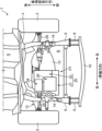
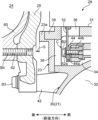
図1は、本発明の第1実施形態に係るパワートレイン構造が適用された車両の前部平面図であり、図2は、パワートレインを右方から視た車両の断面図である。
[First embodiment]
FIG. 1 is a front plan view of a vehicle to which a powertrain structure according to a first embodiment of the invention is applied, and FIG. 2 is a cross-sectional view of the vehicle as seen from the right side of the powertrain.
図1及び図2に示す車両1は、内燃焼機関を備えておらず、走行用の後記モータ21によって車輪(前輪)2を駆動して走行する電気自動車(本発明の電動車両の一例)である。
A vehicle 1 shown in FIGS. 1 and 2 is an electric vehicle (an example of an electric vehicle of the present invention) that does not have an internal combustion engine and runs by driving wheels (front wheels) 2 with a
車両1のモータルームR内には、車室SとモータルームRとを前後に仕切るダッシュパネル4と、このダッシュパネル4の前側に結合されて車両前後方向に延びる左右一対のフロントサイドフレーム6と、これらフロントサイドフレーム6の下方に配置されたサブフレーム12とが設けられている。左右のフロントサイドフレーム6の前端には、圧縮変形により衝撃吸収可能なクラッシュカン8が各々固定され、これらクラッシュカン8の前端部に跨って車幅方向に延在するバンパレインフォースメント10が固定されている。
In the motor room R of the vehicle 1, there are a dash panel 4 that partitions the vehicle room S and the motor room R in the front and rear, and a pair of left and right
左右のフロントサイドフレーム6の間の空間には、車両1の駆動輪である前輪2を回転駆動するためのパワートレインPTが配置されている。
In the space between the left and right
パワートレインPTは、モータマウント装置14を介して左右のフロントサイドフレーム6に懸架された状態で当該フロントサイドフレーム6に支持されるとともに、前記サブフレーム12のモータサポートメンバ12aにより下方から支持されている。なお、パワートレインPTは、車幅方向における両フロントサイドフレーム6の中央よりも左寄りの位置に配置されており、よって、左側のモータマウント装置14とパワートレインPTとの間には中継ブラケット13が介設されている。
The power train PT is supported by the left and right
パワートレインPTは、走行用のモータ21及びトランスアクスル22からなる駆動ユニット20と、電動コンプレッサ24と、インバータ26と、ドライブシャフト28等とを備えている。
The power train PT includes a
前記モータ21は、図外のモータ本体と、このモータ本体が収容されたモータケース30とを有する。モータ本体は、例えば三相交流同期モータからなり、車幅方向に延びる出力軸21a(図9参照)の周囲に永久磁石が備えられてなるロータと、このロータの外周に配置された複数のコイルからなるステータとを備えている。前記ステータの複数のコイルの各々には、位相差を有した交流電力がインバータ26から供給される。この電力供給を受けて出力軸21a(ロータ)が回転する。
The
モータケース30は、両端が閉じられた車幅方向に延びる概略中空円筒状の形状を有している。モータケース30は、所定の厚み寸法を有した例えばアルミニウム合金等の鋳造品からなり、高い剛性を備えた高強度部材である。モータケース30は、図5に示すように、モータ本体が収容されるモータ本体収容室32と、その上部に設けられる電気接続室34とを備えている。モータ21(モータ本体)とインバータ26とは、後に詳述する通り、この電気接続室34内で互いに電気的に接続されている。
The
前記トランスアクスル22は、モータ21の出力を前輪2に伝達するためのものであって、図外の減速機構及び差動機構と、これらの機構が収容されたアクスルケース70とを有する。図1に示すように、トランスアクスル22はモータ21の左端に固定されている。そして、このトランスアクスル22と左右の前輪2とが各々ドライブシャフト28を介して連結されることにより、モータ21の出力(回転)がトランスアクスル22及びドライブシャフト28を介して左右の前輪2に各々伝達される。つまり、前輪2がモータ21により回転駆動される。
The
前記インバータ26は、モータ21に電力を供給するものである。より詳しくは、インバータ26は、例えば車両1の車室フロアの下側等に配置された図外のリチウムイオン電池等の二次電池とケーブルを介して接続されており、この二次電池からの直流電力を、位相差を有した三相交流電力に変換してモータ21に供給する。
The
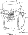
図2~図4に示すように、インバータ26は、インバータ回路を有した回路基板等(図示省略)と、当該回路基板等が収容された平面視矩形の箱形のインバータケース50とを備えている。インバータ26には、前記回路基板から伸びてインバータケース50の下面から下向きに突出する3本のバスバー52が設けられている。これらバスバー52は、大容量の前記三相交流電力をモータ21に供給することが可能な板状の導体であり、各々板厚方向が車両前後方向となるようにそれらの向きが揃えられた状態で、車幅方向に等間隔で一列に配列されている。
As shown in FIGS. 2 to 4, the
インバータ26は、モータ21の上部に固定されている。具体的には、モータケース30の上部には、略平坦なインバータ取付面31が形成されており、このインバータ取付面31上にインバータ26が重ねられている。インバータケース50の側面のうち主にコーナ部分を含む複数箇所(少なくとも4箇所以上)には、インバータケース50の下面に沿って外向きに伸びる取付脚部54が備えられており、これら取付脚部54に形成された取付孔54aを通じて、ボルトB1(図6参照)がインバータ取付面31のねじ孔31bに螺合、挿入されている。これにより、インバータ26がモータ21の上部に重ねられた状態で当該モータ21に締結(固定)されている。
The
モータケース30の前記インバータ取付面31には、車幅方向に細長い平面視オーバル形状の上面開口部36が形成されている。インバータ26の前記3本のバスバー52は、この上面開口部36を通じてモータケース30内に挿入され、前記電気接続室34に配置されている。
The
インバータ26の下面、当例では、前記複数の取付脚部54の一部又は全部(少なくとも3つ以上)の下面には、下向きに伸びる位置決めピン56が設けられており、これらの位置決めピン56が、インバータ取付面31に形成されたピン孔31aに挿入されている。つまり、モータ21へのインバータ26の組付作業の際には、位置決めピン56がピン孔31aに挿入されることでモータ21とインバータ26とが相互に位置決めされる。これにより、上面開口部36に対してバスバー52が誘導され、インバータ取付面31(上面開口部36の周縁部)との衝突によるバスバー52の損傷が防止されるのである。
Positioning pins 56 extending downward are provided on the lower surface of the
なお、図4に示すように、モータケース30の下面からの各位置決めピン56の先端までの軸長は、同下面からのバスバー52の出代寸法(突出長さ)Lよりも長く設定されている。これにより、モータ21への組付け前などには、バスバー52を接地させることなく、すなわち、接地によるバスバー52の変形等を招くことなく、各位置決めピン56を介してインバータ26をテーブル等の平面上に自立させることが可能になっている。
As shown in FIG. 4, the axial length from the bottom surface of the
図3~図5に示すように、電気接続室34内における各バスバー52の前方に対向する位置には、板状の導体からなるモータ側端子44が各々備えられており、これらモータ側端子44に各バスバー52が各々電気的に接続されている。具体的には、バスバー52及びモータ側端子44には貫通孔からなる固定孔52a、44aが設けられており、さらに、モータ側端子44の前面にはナット部材44bが固定されている。そして、図5に示すように、バスバー52の後方から前記固定孔52a、44aにボルトBが挿入されて、当該ボルトBがナット部材44bに螺合、挿入されている。これにより、バスバー52とモータ側端子44とが相互に締結されて電気的に接続されている。なお、バスバー52とモータ側端子44との当該接続部分を導体接続部Cと称す。
As shown in FIGS. 3 to 5, motor-
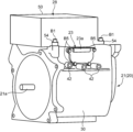
モータケース30の後面には、電気接続室34を後方に解放する後面開口部38(本発明の開口部に相当する)が設けられている。この後面開口部38は、バスバー52とモータ側端子44との上記締結作業を行うために、作業者が電気接続室34内にアクセスするためのものである。後面開口部38は、車幅方向に細長い後面視オーバル形状の開口部であって、車幅方向における前記上面開口部36と略同位置に設けられている。
The rear face of the
図5~図7に示すように、後面開口部38はアルミニウム合金等からなるカバー部材23により塞がれている。カバー部材23は、後面視略長方形の板状であり、ボルトB5によりモータケース30の後面に着脱可能に締結されている。具体的には、カバー部材23の四隅部分には厚み方向に貫通する取付孔(図示省略)が形成されており、ボルトB5が、当該取付孔を通じて後面開口部38の周縁部に形成されたねじ孔40に螺合、挿入されている。
As shown in FIGS. 5 to 7, the
前記電動コンプレッサ24は、空調システム内を循環する空調用の冷媒を圧縮するためのものである。電動コンプレッサ24は、冷媒を圧縮するコンプレッサ本体と、当該コンプレッサ本体が収容されたコンプレッサケース60とを備えている。
The
電動コンプレッサ24は、車幅方向に伸びる概略円柱状の形状であり、モータ21の後方に配置され、ブラケット25を介して当該モータ21に固定されている。
The
詳しく説明すると、図7~図9に示すように、モータケース30の後面であって後面開口部38の下方には、車幅方向に並んだ複数(当例では3つ)のボス部42が後向きに突設されており、これらボス部42に、後面視で略三角形の板状のブラケット25が固定されている。ブラケット25には、その底辺に沿って厚み方向に貫通する複数(当例では3つ)の取付孔(図示省略)が形成されており、ボルトB3が、当該取付孔を通じてボス部42のねじ孔42aに螺合、挿入されることにより、モータ21に当該ブラケット25が固定されている。
More specifically, as shown in FIGS. 7 to 9, on the rear surface of the
ブラケット25の上端部(頂部)、及び該ブラケット25における前記取付孔の上方であって車幅方向に互いに離間した位置(2カ所)には各々ねじ孔72が設けられている。一方、コンプレッサケース60の上部及び下部には、前記ねじ孔72に対応する各々車両前後方向に貫通した取付孔62が形成されており、ボルトB4が、電動コンプレッサ24の後方から当該取付孔62を通じて前記ねじ孔72に螺合、挿入されている。これにより、電動コンプレッサ24がブラケット25を介してモータ21に固定されている。なお、図8及び図9に示すように、ブラケット25は、モータケース30の後面に固定されてその固定位置(ボルトB3の締結位置)から上方に延在しており、電動コンプレッサ24は、この固定位置よりも上方の位置でブラケット25に固定されている。従って、電動コンプレッサ24は、ブラケット25を介してモータ21に片持ち状態で支持されていると言える。
Screw holes 72 are provided at the upper end (top) of the
なお、図5、図8及び図9に示すように、電動コンプレッサ24は、モータケース30のカバー部材23の後方、すなわちインバータ26のバスバー52とモータ21のモータ側端子44との導体接続部Cの後方に位置している。
As shown in FIGS. 5, 8 and 9, the
そのため、図5及び図7に示すように、カバー部材23の後面には、車両前突時にモータ21と電動コンプレッサ24(ブラケット25)とが相対的に接近して互いに衝突した場合にその衝突荷重を受け止めるための車幅方向に延在する凸部23a(荷重受け止め部)が設けられている。
Therefore, as shown in FIGS. 5 and 7, a collision load is applied to the rear surface of the
凸部23aは、カバー部材23の後面のうち、車両後面視においてモータケース30の前記後面開口部38の周縁部と重なる部分の一部、具体的には、カバー部材23の後面のうちその上縁部がそれ以外の部分よりも後方に突出するように形成されることにより、当該カバー部材23に設けられている。換言すれば、カバー部材23のうちその上縁部の肉厚が、それ以外の部分の肉厚よりも大きくなるように形成されることにより、当該カバー部材23に設けられている。
The
[作用効果]
上記車両1のパワートレインPTは、車両1の前部のモータルームR内に配置された走行用のモータ21と、その上部に組み付けられたインバータ26と、モータケース30の内部で当該モータ21とインバータ26とを電気的に接続する導体接続部Cと、モータ21(モータケース30)の後面に形成された後面開口部38と、モータケース30に組み付けられて前記後面開口部38を塞ぐカバー部材23と、このカバー部材23の後方に配置されて、ブラケット25を介してモータ21に固定された車両用補機である電動コンプレッサ24とを備えている。このようなパワートレインPTの構造によると、車両前突時には、モータ21により衝突荷重が受け止められながら当該モータ21と共に電動コンプレッサ24が後退する。そのため、高電圧部材である電動コンプレッサ24が良好に保護される。
[Effect]
The power train PT of the vehicle 1 includes a
この際、衝突荷重が非常に大きく、モータ21と共に後退した電動コンプレッサ24がダッシュパネル4に当接してその後退が滞ると、電動コンプレッサ24がブラケット25を介して後ろからモータ21に衝突し、これによりカバー部材23が突き破られて導体接続部Cが破損することが考えられる。
At this time, if the collision load is so large that the
しかし、上記パワートレインPTの構造によると、カバー部材23に前記凸部23aが設けられているため、そのような事態の発生が効果的に抑制される。
However, according to the structure of the power train PT, since the
すなわち、凸部23aは、カバー部材23のうち後面開口部38の周縁部(上縁部)と重なる部分に設けられているので、電動コンプレッサ24(ブラケット25)がモータ21に衝突する際の衝突荷重は、前後方向に厚みを持った凸部23aで受け止められつつモータケース30に伝達されることとなる。
That is, since the
また、凸部23aの部分では、カバー部材23とブラケット25との間隔Gが、当該凸部23aが設けられていない場合に比べて狭くなっているので(凸部23aの部分におけるカバー部材23とブラケット25との間隔Gが、その他の部分におけるカバー部材23とブラケット25との間隔Gよりも狭くなっているので)、電動コンプレッサ24(ブラケット25)がモータ21に衝突する際に生じる衝撃応力も低く抑えられる。これにより、カバー部材23が破損することが抑制される。
In addition, since the gap G between the
従って、上記のようなパワートレインPTの構造によると、インバータ26とモータ21との導体接続部Cを覆ったカバー部材23が車両前突時に破損すること、ひいては導体接続部Cが破損することが効果的に抑制される。よって、インバータ26とモータ21との導体接続部Cをより確実に保護することができると言える。
Therefore, according to the structure of the power train PT as described above, the
また、前後方向に厚みのある凸部23aを備えた前記カバー部材23を取り外せば、モータケース30の後面とブラケット25との間に比較的広い空間を確保できるため、作業者は、その空間を利用して後面開口部38から導体接続部Cに難なくアクセスすることが可能となる。そのため、バスバー52とモータ側端子44との締結(接続)作業や締結解除作業を容易に行うことができる、という利点もある。
Further, by removing the
なお、上記実施形態では、カバー部材23の周縁部のうち上縁部にのみ凸部23aが設けられているが、これは次のような理由よる。すなわち、上述のよるに、電動コンプレッサ24がブラケット25を介して片持ち状態でモータケース30に固定されている上記パワートレインPTの構造では、車両前突時、モータ21と共に後退した電動コンプレッサ24がダッシュパネル4に当接してその後退が滞ると、ダッシュパネル4に押されてブラケット25が前記固定位置(ボルトB3の締結位置)を支点として前方に変形しつつ電動コンプレッサ24が当該ブラケット25を介してモータ21に衝突することとなる。そのため、カバー部材23の周縁部のうち少なくとも上縁部に凸部23aが設けられていれば、電動コンプレッサ24(ブラケット25)がモータ21に衝突する際の衝突荷重を当該凸部23aで受け止めつつモータケース30に伝達することができ、また、当該衝突時に生じる衝撃応力を低く抑えることも可能となる。つまり、カバー部材23のうち必要最小限の部分に凸部23aを設けることで、カバー部材23の軽量化、ひいてはパワートレインPTの軽量化を図りながら上記の作用効果を享受できるようにしているのである。
In the above-described embodiment, only the upper edge portion of the
但し、カバー部材23の上縁部に加えて下縁部に沿った凸部23aが設けられている構造(図示省略)や、図10に示すように、カバー部材23の周縁部の全体に亘って凸部23aが設けられている構造を採用するようにしてもよい。これらの構造によれば、電動コンプレッサ24(ブラケット25)がモータ21に衝突する際の衝突荷重をより広い範囲で受け止めつつ後面開口部38の周縁部のより広い範囲に伝達することが可能となる。従って、上記衝突荷重を効果的に分散させることができ、その結果、車両前突時のカバー部材23の破損、ひいては導体接続部Cの破損をより高度に抑制することが可能となる。
However, in addition to the upper edge of the
[第2実施形態]
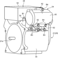
図11は、本発明の第2実施形態に係るパワートレイン構造が適用された車両の前部平面図である。なお、図11は、第1実施形態の図5に対応する図である。
[Second embodiment]
FIG. 11 is a front plan view of a vehicle to which the powertrain structure according to the second embodiment of the invention is applied. Note that FIG. 11 is a diagram corresponding to FIG. 5 of the first embodiment.
第2実施形態のパワートレインPTの構造は、以下に説明する点が第1実施形態と異なる以外、基本的な構造は第1実施形態と同じである。 The structure of the power train PT of the second embodiment is basically the same as that of the first embodiment, except for the points described below.
第1実施形態(図5に示す実施形態)では、カバー部材23の後面のうちその上縁部に凸部23aが形成されている。換言すれば、カバー部材23のうち、その上縁部の肉厚が、それ以外の部分の肉厚よりも大きくなるように形成されている。この構造により、電動コンプレッサ24(ブラケット25)がモータ21に衝突する際の衝突荷重を、前後方向に厚みを持った凸部23aで受け止めつつモータケース30に伝達させている。
In the first embodiment (embodiment shown in FIG. 5), a
これに対して、第2実施形態では、図11に示すように、モータケース30の後面開口部38の周縁部のうち上縁部に、それ以外の部分よりも後方に突出した凸部39が設けられている。換言すれば、モータケース30の前記後面開口部38の上縁部(周縁部の一部)における前後方向の肉厚がそれ以外の部分の肉厚よりも大きくなるように形成されている。なお、カバー部材23は、全体が略一定の厚みであるが、前記凸部39に対応する部分が断面クランク形状に形成されている。
On the other hand, in the second embodiment, as shown in FIG. 11, a
このような第2実施形態のパワートレインPTの構造によっても第1実施形態と同等の作用効果を享受することができる。すなわち、電動コンプレッサ24(ブラケット25)がモータ21に衝突する際の衝突荷重は、カバー部材23を介してモータケース30に入力されるが、この際、当該衝突荷重は、前後方向に厚みを持った凸部39で受け止められつつ当該モータケース30の他の部分に伝達される。しかも、凸部39の部分では、カバー部材23とブラケット25との間隔Gが、当該凸部39が設けられていない場合に比べて狭くなっているので(換言すれば、凸部39の部分におけるカバー部材23とブラケット25との間隔Gが、その他の部分におけるカバー部材23とブラケット25との間隔Gよりも狭くなっているので)、電動コンプレッサ24(ブラケット25)がモータ21に衝突する際の衝撃応力も緩和されることとなる。
With such a structure of the powertrain PT of the second embodiment as well, it is possible to enjoy effects equivalent to those of the first embodiment. That is, the collision load when the electric compressor 24 (bracket 25) collides with the
従って、このような第2実施形態のパワートレインPTの構造によっても車両前突時のカバー部材23の破損、ひいては導体接続部Cの破損を抑制することができ、よって、インバータ26とモータ21との導体接続部Cを保護することができると言える。
Therefore, even with the structure of the power train PT of the second embodiment, it is possible to suppress the damage of the
なお、この第2実施形態のパワートレインPTの構造においては、後面開口部38の上縁部に加えて下縁部に沿った凸部39が設けられている構造や(図示省略)、図12に示すように、カバー部材23の周縁部の全体に沿って凸部39が設けられている構造、つまり、後面開口部38の周縁部に、後方に向かって突出するボス部を設けた構造を採用するようにしてもよい。この場合には、同図に示すように、カバー部材23は全体が平坦な板状の形状でよい。
In addition, in the structure of the power train PT of the second embodiment, in addition to the upper edge portion of the rear surface opening 38, a
これらの構造によれば、電動コンプレッサ24(ブラケット25)がモータ21に衝突する際の衝突荷重をより広い範囲で受け止めつつモータケース30の他の部分に伝達することが可能となる。従って、上記衝突荷重を効果的に分散させることができ、その結果、車両前突時のカバー部材23の破損、ひいては導体接続部Cの破損をより高度に抑制することが可能となる。
With these structures, it is possible to transmit the impact load to other parts of the
[変形例]
以上説明した各実施形態のパワートレインPTの構造は、本発明に係る車両のパワートレイン構造の好ましい実施形態の例示であってその具体的な構成は本発明の要旨を逸脱しない範囲で適宜変更可能である。
[Modification]
The structure of the powertrain PT of each embodiment described above is an example of a preferred embodiment of the powertrain structure of the vehicle according to the present invention, and the specific structure can be changed as appropriate without departing from the gist of the present invention. is.
上記実施形態では、電動コンプレッサ24はブラケット25を介してモータ21の後部に固定されているが、本発明はこの構造には限らない。例えば、モータ21に固定されることなく、電動コンプレッサ24が当該モータ21の後方に配置されているようなパワートレインPTの構造についても本発明は適用可能である。
In the above embodiment, the
上記実施形態では、車両用補機として電動コンプレッサ24がパワートレインPTに設けられている例について説明したが、当該車用補機は電動コンプレッサ24に限らず、その他の車両用補機であってもよい。
In the above embodiment, an example in which the
上記実施形態では、本発明を電気自動車のパワートレインPTに適用した例について説明したが、本発明はこれに限らず、車輪の駆動源としてモータと内燃機関とが併用される、あるいはモータの駆動源として内燃機関が用いられる、いわゆるハイブリッド自動車にも適用可能である。 In the above embodiment, an example in which the present invention is applied to the power train PT of an electric vehicle has been described, but the present invention is not limited to this. It can also be applied to a so-called hybrid vehicle in which an internal combustion engine is used as a power source.
1 車両
4 ダッシュパネル
20 駆動ユニット
21 モータ
23 カバー部材
23a 凸部(荷重受け止め部)
24 電動コンプレッサ(車両用補機)
25 ブラケット
26 インバータ
30 モータケース
38 後面開口部
52 バスバー
44 モータ側端子
PT パワートレイン
R モータルーム
Reference Signs List 1 vehicle 4
24 electric compressor (vehicle accessory)
25
Claims (7)
前記モータの上部に組み付けられたインバータと、
前記モータケースの内部で、導体同士の接続により前記モータと前記インバータとを電気的に接続する導体接続部と、
車両前後方向における前記モータケースの後面に形成されて、前記導体接続部にアクセスすることを許容する開口部と、
前記モータケースに組み付けられて前記開口部を塞ぐカバー部材と、
車両前後方向における前記カバー部材の後方に配置された車両用補機と、
車両前後方向における後面視で、前記カバー部材と前記開口部の周縁部とが重なる部分に設けられて、前記モータと前記車両用補機とが相対的に接近して互いに衝突したときにその衝突荷重を受け止める荷重受け止め部と、を備えていることを特徴とする車両のパワートレイン構造。 A structure of the powertrain of an electric vehicle having a motor case and including a powertrain including a motor for traveling arranged in a motor room in the front part of the vehicle,
an inverter mounted on the top of the motor;
a conductor connecting portion that electrically connects the motor and the inverter by connecting conductors inside the motor case;
an opening formed in the rear surface of the motor case in the vehicle front-rear direction to allow access to the conductor connecting portion;
a cover member that is assembled to the motor case and closes the opening;
a vehicle auxiliary machine disposed behind the cover member in the vehicle front-rear direction;
When viewed from the rear in the front-rear direction of the vehicle, the cover member and the peripheral edge portion of the opening overlap each other to prevent collision when the motor and the vehicle auxiliary machine come relatively close to each other and collide with each other. A powertrain structure for a vehicle, comprising: a load receiving portion for receiving a load.
前記車両用補機は、コンプレッサであることを特徴とする、車両のパワートレイン構造。 In the vehicle powertrain structure according to claim 1,
A vehicle powertrain structure, wherein the vehicle accessory is a compressor.
前記荷重受け止め部は、前記カバー部材のうち前記開口部の周縁部に対応する部分の全部又は一部と前記車両用補機との車両前後方向における間隔が、それ以外の部分における前記カバー部材と前記車両用補機との車両前後方向における間隔よりも小さくなるように設けられたものである、ことを特徴とする車両のパワートレイン構造。 In the vehicle powertrain structure according to claim 1 or 2,
In the load receiving portion, the distance in the vehicle front-rear direction between all or part of a portion of the cover member corresponding to the peripheral edge portion of the opening and the vehicle accessory is equal to that of the other portion of the cover member. A powertrain structure for a vehicle, characterized in that the powertrain structure is provided so as to be smaller than a space in the vehicle front-rear direction with respect to the vehicle auxiliary machine.
前記荷重受け止め部は、前記カバー部材のうち前記開口部の周縁部に対応する部分の全部又は一部の車両前後方向における肉厚が、それ以外の部分の肉厚よりも大きくなるように形成されたものである、ことを特徴とする車両のパワートレイン構造。 In the vehicle powertrain structure according to claim 3,
The load receiving portion is formed such that the thickness of all or part of the portion of the cover member corresponding to the peripheral edge portion of the opening in the vehicle front-rear direction is greater than the thickness of the other portions. A vehicle powertrain structure characterized by:
前記荷重受け止め部は、前記モータケースにおける前記開口部の周縁部の全部又は一部の車両前後方向の肉厚が、それ以外の部分の肉厚よりも大きくなるように形成されたものである、ことを特徴とする車両のパワートレイン構造。 In the vehicle powertrain structure according to claim 3,
The load receiving portion is formed such that the thickness in the vehicle front-rear direction of all or part of the peripheral edge portion of the opening in the motor case is larger than the thickness of other portions. A vehicle powertrain structure characterized by:
前記車両用補機は、ブラケットを介して前記モータケースに取り付けられており、
前記荷重受け止め部は、車両前後方向における後面視で、前記ブラケットと前記開口部の周縁部とが重なる部分に設けられている、ことを特徴とする車両のパワートレイン構造。 In the vehicle powertrain structure according to any one of claims 1 to 5,
The vehicle accessory is attached to the motor case via a bracket,
The powertrain structure for a vehicle, wherein the load receiving portion is provided at a portion where the bracket and the peripheral edge portion of the opening overlap when viewed from the rear in the vehicle front-rear direction.
前記ブラケットは、前記モータケースの後面に固定されてその固定位置から上方に延在しており、
前記車両用補機は、前記固定位置よりも上方の位置で前記ブラケットに固定されることにより、当該ブラケットを介して前記モータに片持ち状態で支持されている、ことを特徴とする車両のパワートレイン構造。
In the vehicle powertrain structure according to claim 6,
The bracket is fixed to the rear surface of the motor case and extends upward from the fixed position,
The vehicular accessory is fixed to the bracket at a position higher than the fixing position, thereby being supported by the motor in a cantilever manner via the bracket. train structure.
Priority Applications (1)
| Application Number | Priority Date | Filing Date | Title |
|---|---|---|---|
| JP2019150968A JP7338317B2 (en) | 2019-08-21 | 2019-08-21 | Vehicle powertrain structure |
Applications Claiming Priority (1)
| Application Number | Priority Date | Filing Date | Title |
|---|---|---|---|
| JP2019150968A JP7338317B2 (en) | 2019-08-21 | 2019-08-21 | Vehicle powertrain structure |
Publications (2)
| Publication Number | Publication Date |
|---|---|
| JP2021030802A JP2021030802A (en) | 2021-03-01 |
| JP7338317B2 true JP7338317B2 (en) | 2023-09-05 |
Family
ID=74677033
Family Applications (1)
| Application Number | Title | Priority Date | Filing Date |
|---|---|---|---|
| JP2019150968A Active JP7338317B2 (en) | 2019-08-21 | 2019-08-21 | Vehicle powertrain structure |
Country Status (1)
| Country | Link |
|---|---|
| JP (1) | JP7338317B2 (en) |
Cited By (1)
| Publication number | Priority date | Publication date | Assignee | Title |
|---|---|---|---|---|
| EP4624270A1 (en) * | 2024-03-28 | 2025-10-01 | Mazda Motor Corporation | Vehicle powertrain structure |
Families Citing this family (5)
| Publication number | Priority date | Publication date | Assignee | Title |
|---|---|---|---|---|
| EP4506195A4 (en) * | 2022-04-04 | 2025-06-11 | Nissan Motor Co., Ltd. | DRIVE UNIT FOR AN ELECTRIC VEHICLE |
| JP7483793B2 (en) * | 2022-06-17 | 2024-05-15 | 本田技研工業株式会社 | High voltage device mounting structure for vehicle |
| JP7770300B2 (en) * | 2022-12-27 | 2025-11-14 | 株式会社クボタ | electric work vehicle |
| CN121794164A (en) * | 2023-08-31 | 2026-04-03 | 日产自动车株式会社 | Vehicle-mounted equipment structure |
| JP2026011256A (en) | 2024-07-11 | 2026-01-23 | トヨタ自動車株式会社 | Electric vehicles |
Citations (4)
| Publication number | Priority date | Publication date | Assignee | Title |
|---|---|---|---|---|
| JP2010183794A (en) | 2009-02-09 | 2010-08-19 | Honda Motor Co Ltd | Rotary electric machine device and method for manufacturing the same |
| JP2012140052A (en) | 2010-12-28 | 2012-07-26 | Mazda Motor Corp | Electric vehicle |
| JP2012170172A (en) | 2011-02-10 | 2012-09-06 | Toyota Motor Corp | Inverter integral driving device |
| JP2015140059A (en) | 2014-01-28 | 2015-08-03 | トヨタ自動車株式会社 | Connector protection structure of motor |
Family Cites Families (2)
| Publication number | Priority date | Publication date | Assignee | Title |
|---|---|---|---|---|
| JP4935567B2 (en) * | 2007-08-02 | 2012-05-23 | トヨタ自動車株式会社 | housing |
| JP2011062023A (en) * | 2009-09-11 | 2011-03-24 | Aisin Aw Co Ltd | Electrical connection device |
-
2019
- 2019-08-21 JP JP2019150968A patent/JP7338317B2/en active Active
Patent Citations (4)
| Publication number | Priority date | Publication date | Assignee | Title |
|---|---|---|---|---|
| JP2010183794A (en) | 2009-02-09 | 2010-08-19 | Honda Motor Co Ltd | Rotary electric machine device and method for manufacturing the same |
| JP2012140052A (en) | 2010-12-28 | 2012-07-26 | Mazda Motor Corp | Electric vehicle |
| JP2012170172A (en) | 2011-02-10 | 2012-09-06 | Toyota Motor Corp | Inverter integral driving device |
| JP2015140059A (en) | 2014-01-28 | 2015-08-03 | トヨタ自動車株式会社 | Connector protection structure of motor |
Cited By (1)
| Publication number | Priority date | Publication date | Assignee | Title |
|---|---|---|---|---|
| EP4624270A1 (en) * | 2024-03-28 | 2025-10-01 | Mazda Motor Corporation | Vehicle powertrain structure |
Also Published As
| Publication number | Publication date |
|---|---|
| JP2021030802A (en) | 2021-03-01 |
Similar Documents
| Publication | Publication Date | Title |
|---|---|---|
| JP7338317B2 (en) | Vehicle powertrain structure | |
| US11492044B2 (en) | Vehicle front structure | |
| CN102458891B (en) | Vehicle component mounting arrangement | |
| US8770326B2 (en) | Vehicle component mounting arrangement | |
| JP5446537B2 (en) | Electric vehicle mounting structure | |
| CN102458889B (en) | Vehicle component mounting structure | |
| JP4924671B2 (en) | Electric vehicle mounting structure | |
| EP2670613A1 (en) | Vehicle equipment mounting structure | |
| JP6582025B2 (en) | Battery unit | |
| JP2014009626A (en) | Electric compressor | |
| JP2013103585A (en) | Protective structure for power control unit | |
| JP4968292B2 (en) | Electric vehicle mounting structure | |
| JP2011020624A (en) | Mounting structure for electric vehicle | |
| JP5817627B2 (en) | Electric vehicle | |
| CN112477599A (en) | Structure for mounting electrical equipment on vehicle | |
| EP3385103B1 (en) | High-voltage device | |
| JP2013103584A (en) | Protective structure for power control unit | |
| US20140238765A1 (en) | Electric car | |
| EP4624210A1 (en) | Vehicle front structure | |
| WO2021176602A1 (en) | Vehicle-mounted structure of inverter | |
| JP2018024384A (en) | In-vehicle structure of power control unit | |
| US20250282208A1 (en) | Power unit mounting structure | |
| JP7740524B2 (en) | Electric vehicle drive unit | |
| WO2022249375A1 (en) | Vibration-proof structure for part attached to housing of electrical device installed on vehicle | |
| US20230361657A1 (en) | Integrated unit |
Legal Events
| Date | Code | Title | Description |
|---|---|---|---|
| A621 | Written request for application examination |
Free format text: JAPANESE INTERMEDIATE CODE: A621 Effective date: 20220720 |
|
| A977 | Report on retrieval |
Free format text: JAPANESE INTERMEDIATE CODE: A971007 Effective date: 20230713 |
|
| TRDD | Decision of grant or rejection written | ||
| A01 | Written decision to grant a patent or to grant a registration (utility model) |
Free format text: JAPANESE INTERMEDIATE CODE: A01 Effective date: 20230725 |
|
| A61 | First payment of annual fees (during grant procedure) |
Free format text: JAPANESE INTERMEDIATE CODE: A61 Effective date: 20230807 |
|
| R150 | Certificate of patent or registration of utility model |
Ref document number: 7338317 Country of ref document: JP Free format text: JAPANESE INTERMEDIATE CODE: R150 |