JP7336855B2 - Coil parts and electronic equipment - Google Patents

Coil parts and electronic equipment Download PDF

Info

Publication number
JP7336855B2
JP7336855B2 JP2019036842A JP2019036842A JP7336855B2 JP 7336855 B2 JP7336855 B2 JP 7336855B2 JP 2019036842 A JP2019036842 A JP 2019036842A JP 2019036842 A JP2019036842 A JP 2019036842A JP 7336855 B2 JP7336855 B2 JP 7336855B2
Authority
JP
Japan
Prior art keywords
coil component
core
winding
base portion
base
Prior art date
Legal status (The legal status is an assumption and is not a legal conclusion. Google has not performed a legal analysis and makes no representation as to the accuracy of the status listed.)
Active
Application number
JP2019036842A
Other languages
Japanese (ja)
Other versions
JP2020141078A (en
Inventor
麻 山本
努 小島
Current Assignee (The listed assignees may be inaccurate. Google has not performed a legal analysis and makes no representation or warranty as to the accuracy of the list.)
Taiyo Yuden Co Ltd
Original Assignee
Taiyo Yuden Co Ltd
Priority date (The priority date is an assumption and is not a legal conclusion. Google has not performed a legal analysis and makes no representation as to the accuracy of the date listed.)
Filing date
Publication date
Application filed by Taiyo Yuden Co Ltd filed Critical Taiyo Yuden Co Ltd
Priority to JP2019036842A priority Critical patent/JP7336855B2/en
Publication of JP2020141078A publication Critical patent/JP2020141078A/en
Application granted granted Critical
Publication of JP7336855B2 publication Critical patent/JP7336855B2/en
Active legal-status Critical Current
Anticipated expiration legal-status Critical

Links

Images

Description

本発明は、コイル部品及び電子機器に関する。 The present invention relates to coil components and electronic equipment.

周回部を形成する導線と金属板で形成される端子電極とを電気的に接続するために、導線の端部と金属板の一部とをアーク溶接又はレーザー溶接によって接合することが知られている(例えば、特許文献1、2)。 In order to electrically connect the conducting wire forming the winding portion and the terminal electrode formed of the metal plate, it is known to join the end portion of the conducting wire and a part of the metal plate by arc welding or laser welding. (For example, Patent Documents 1 and 2).

特開2009-158777号公報JP 2009-158777 A 特開2018-41852号公報JP 2018-41852 A

導線と金属板の一部とを溶接によって接合する場合、溶融部分が盛り上がって丸みを帯びた溶接部が形成される。土台部上に丸みを帯びた溶接部が形成される場合、溶接部に土台部から引き離す方向の外力が加わることがあり、溶接部が土台部から剥離してしまうことがある。 When joining a conductive wire and a portion of a metal plate by welding, the molten portion rises to form a rounded welded portion. When a rounded welded portion is formed on the base portion, an external force may be applied to the welded portion in a direction to separate the welded portion from the base portion, and the welded portion may separate from the base portion.

本発明は、上記課題に鑑みなされたものであり、溶接部の土台部からの剥離を抑制することを目的とする。 The present invention has been made in view of the above problems, and an object of the present invention is to suppress separation of a welded portion from a base portion.

本発明は、基体部と、前記基体部の一部に巻回される導線から形成される周回部と、前記基体部の一部の表面に設けられ金属板からなる土台部と、前記土台部上に形成され、前記金属板の一部と前記導線とが溶接して形成される溶接部と、前記溶接部と前記土台部の界面の外周の少なくとも一部に前記土台部から前記溶接部の表面に盛り上がって設けられる金属フィレットと、を有し、前記導線が前記周回部から引き出される引出部と電気的に接続される端子電極と、を備え、前記溶接部の最大径部は、前記土台部から離れて前記土台部の上方に位置し、前記金属フィレットの前記界面とは反対側における端部は、前記最大径部よりも前記溶接部に対して外側に位置する、コイル部品である。 The present invention comprises a base portion, a winding portion formed of a conductive wire wound around a portion of the base portion, a base portion formed of a metal plate provided on a surface of a portion of the base portion, and the base portion. and a weld portion formed by welding a portion of the metal plate and the conductor wire, and a portion of the weld portion from the base portion to at least a part of the outer periphery of the interface between the weld portion and the base portion. a metal fillet protruding from the surface, and a terminal electrode electrically connected to a lead-out portion in which the lead wire is led out from the winding portion , wherein the maximum diameter portion of the weld portion is the base. The coil component is a coil component in which an end portion of the metal fillet located above the base portion away from the base portion and located on the side opposite to the interface of the metal fillet is located outside of the maximum diameter portion with respect to the weld portion.

上記構成において、前記金属フィレットは、前記溶接部が設けられている前記基体部の表面を平面視したときに前記界面の外周のうちの少なくとも前記引出部に重なる部分に設けられている構成とすることができる。また、上記構成において、前記引出部は、前記土台部から離れて前記溶接部に接続する構成とすることができる。また、上記構成において、前記引出部は、前記土台部および前記金属フィレットの両方から離れて前記溶接部に接続する構成とすることができる。 In the above configuration, the metal fillet is provided at a portion of the outer circumference of the interface that overlaps at least the lead portion when the surface of the base portion on which the welded portion is provided is viewed in plan. be able to. Further, in the above configuration, the lead-out portion may be separated from the base portion and connected to the weld portion. Further, in the above configuration, the lead-out portion may be configured to be connected to the welded portion while being separated from both the base portion and the metal fillet.

上記構成において、前記金属フィレットは、前記界面の外周の全周にわたって設けられている構成とすることができる。 The said structure WHEREIN: The said metal fillet can be set as the structure provided over the perimeter of the outer periphery of the said interface.

上記構成において、前記金属フィレットは、前記最大径部に接して設けられている構成とすることができる。 The said structure WHEREIN: The said metal fillet can be set as the structure provided in contact with the said maximum diameter part.

上記構成において、前記金属フィレットは錫又は錫を主成分として形成されている構成とすることができる。 In the above structure, the metal fillet may be formed of tin or tin as a main component.

上記構成において、前記導線及び前記溶接部は銅を含んで形成され、前記引出部は前記金属フィレットから離れて前記溶接部に接続している構成とすることができる。 In the above configuration, the lead wire and the welded portion may contain copper, and the lead-out portion may be separated from the metal fillet and connected to the welded portion.

上記構成において、前記端子電極は前記引出部を係止する係止部を有する構成とすることができる。 In the above configuration, the terminal electrode may have a locking portion that locks the lead portion.

上記構成において、前記基体部は巻芯部と前記巻芯部の軸方向における端部に設けられる鍔部とを含むコアであり、前記端子電極は前記鍔部に配置され、前記周回部は前記導線が前記巻芯部に巻回されて形成され、前記引出部は前記導線が前記巻芯部から前記鍔部に配置される前記端子電極に引き出される構成とすることができる。 In the above configuration, the base portion is a core including a winding core portion and a flange portion provided at an end portion in the axial direction of the winding core portion, the terminal electrode is arranged on the flange portion, and the winding portion is the winding portion. A conducting wire may be wound around the winding core portion, and the lead-out portion may be configured such that the conducting wire is led out from the winding core portion to the terminal electrode disposed on the collar portion.

上記構成において、前記基体部は、巻芯部と前記巻芯部の軸方向における端部に設けられる鍔部とを含むコアと、前記コアの外周に配置される外装コアと、を含み、前記端子電極は前記外装コアに配置され、前記周回部は前記導線が前記巻芯部に巻回されて形成され、前記引出部は前記導線が前記巻芯部から前記外装コアに配置される前記端子電極に引き出される構成とすることができる。 In the above configuration, the base includes a core including a winding core and a flange provided at an end of the winding core in the axial direction, and an exterior core disposed on the outer periphery of the core. The terminal electrode is disposed on the exterior core, the winding portion is formed by winding the conductor wire around the winding core portion, and the lead portion is the terminal in which the conductor wire is disposed from the winding core portion to the exterior core. It can be configured to be pulled out to the electrode.

本発明は、上記記載のコイル部品と、前記コイル部品が実装される回路基板と、を備える電子機器である。 According to another aspect of the present invention, there is provided an electronic device comprising the coil component described above and a circuit board on which the coil component is mounted.

本発明によれば、溶接部の土台部からの剥離を抑制することができる。 ADVANTAGE OF THE INVENTION According to this invention, peeling from a base part of a welded part can be suppressed.

図1(a)は、本願発明のコイル部品における端子電極の断面図、図1(b)は、比較例のコイル部品における端子電極の断面図である。FIG. 1(a) is a cross-sectional view of a terminal electrode in a coil component of the present invention, and FIG. 1(b) is a cross-sectional view of a terminal electrode in a coil component of a comparative example. 図2は、本願発明の第1の実施形態に係るコイル部品を示す斜視図である。FIG. 2 is a perspective view showing the coil component according to the first embodiment of the present invention. 図3(a)は、図2のコイル部品を矢印F1側から見た図であり、図3(b)は、矢印F2側から見た図である。3(a) is a view of the coil component in FIG. 2 as seen from the arrow F1 side, and FIG. 3(b) is a view as seen from the arrow F2 side. 図4(a)及び図4(b)は、図2のコイル部品の鍔部での断面図である。4(a) and 4(b) are cross-sectional views of the flange portion of the coil component of FIG. 2. FIG. 図5(a)は、図3(a)のA-A間における端子電極の断面図であり、図5(b)は、溶接部及び金属フィレットを図5(a)の矢印F3側から見た平面図である。FIG. 5(a) is a cross-sectional view of the terminal electrode between AA in FIG. 3(a), and FIG. 5(b) shows the welded portion and the metal fillet viewed from the arrow F3 side in FIG. 5(a). is a plan view. 図6は、図2のコイル部品の端子金属板を説明するための図である。6 is a diagram for explaining a terminal metal plate of the coil component of FIG. 2. FIG. 図7(a)及び図7(b)は、本願発明の第1の実施形態に係るコイル部品の製造方法を説明する図(その1)である。7(a) and 7(b) are diagrams (part 1) for explaining the method of manufacturing the coil component according to the first embodiment of the present invention. 図8(a)から図8(c)は、本願発明の第1の実施形態に係るコイル部品の製造方法を説明する図(その2)である。FIGS. 8A to 8C are diagrams (part 2) illustrating the method of manufacturing the coil component according to the first embodiment of the present invention. 図9は、本願発明の第2の実施形態に係るコイル部品における端子電極の断面図である。FIG. 9 is a cross-sectional view of terminal electrodes in a coil component according to a second embodiment of the present invention. 図10は、シングルライン用のコイル部品の図である。FIG. 10 is a diagram of a coil component for a single line. 図11は、ドラムコアの外周に外装コアが設けられたコイル部品の斜視図である。FIG. 11 is a perspective view of a coil component in which an outer core is provided on the outer periphery of a drum core. 図12は、本願発明の第1の実施形態に係るコイル部品を備える電子機器を示す図である。12A and 12B are diagrams showing an electronic device including the coil component according to the first embodiment of the present invention. FIG.

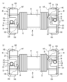
まず、本願発明の構成及び作用効果について説明する。図1(a)は、本願発明のコイル部品における端子電極200の断面図、図1(b)は、比較例のコイル部品における端子電極300の断面図である。本願発明のコイル部品における端子電極200は、溶接部201と、金属板203からなる土台部202と、金属フィレット205と、を有する。溶接部201は、金属板203の一部と導線204とが溶接して形成され、土台部202上に設けられている。溶接部201は、溶接部201と土台部202との間に形成された合金層によって土台部202に接合している。溶接部201は、金属板203の一部と導線204とが溶融して形成されるため、溶融部分が盛り上がって丸みを帯びた形状をしている。溶接部201の最大径部207は土台部202よりも上方に位置している。このため、溶接部201の土台部202側に位置する部分は最大径部207よりも凹んでいる。金属フィレット205は、溶接部201と土台部202の界面の外周の少なくとも一部に土台部202から溶接部201の表面に盛り上がって設けられている。 First, the configuration and effects of the present invention will be described. FIG. 1(a) is a cross-sectional view of a terminal electrode 200 in a coil component of the present invention, and FIG. 1(b) is a cross-sectional view of a terminal electrode 300 in a coil component of a comparative example. A terminal electrode 200 in the coil component of the present invention has a welded portion 201 , a base portion 202 made of a metal plate 203 , and a metal fillet 205 . Welding portion 201 is formed by welding a portion of metal plate 203 and conducting wire 204 and is provided on base portion 202 . Welded portion 201 is joined to base portion 202 by an alloy layer formed between welded portion 201 and base portion 202 . The welded portion 201 is formed by melting a portion of the metal plate 203 and the lead wire 204, so that the melted portion rises and has a rounded shape. A maximum diameter portion 207 of the welded portion 201 is located above the base portion 202 . Therefore, the portion of the welded portion 201 located on the base portion 202 side is recessed from the maximum diameter portion 207 . The metal fillet 205 is provided on at least part of the outer circumference of the interface between the welded portion 201 and the base portion 202 so as to rise from the base portion 202 to the surface of the welded portion 201 .

それに対して、比較例のコイル部品における端子電極300では、溶接部301と金属板303からなる土台部302の界面の外周に金属フィレットが設けられていない。溶接部301の最大径部307が土台部302よりも上方に位置していて、溶接部301の土台部302側に位置する部分が最大径部307よりも凹んでいる。この最大径部307よりも凹んだ部分を凹部306とする。 On the other hand, in the terminal electrode 300 in the coil component of the comparative example, no metal fillet is provided on the outer periphery of the interface between the welded portion 301 and the base portion 302 made up of the metal plate 303 . A maximum diameter portion 307 of the welded portion 301 is located above the base portion 302 , and a portion of the welded portion 301 located on the base portion 302 side is recessed from the maximum diameter portion 307 . A recessed portion 306 is defined as a portion recessed from the maximum diameter portion 307 .

比較例のコイル部品のおける端子電極300のように、溶接部301と土台部302の間に凹部306が形成されている場合、凹部306に外部部材が入り込むことが起こり得る。凹部306に入り込んだ外部部材によって溶接部301に土台部302から引き離す方向の外力が加わり、溶接部301が土台部302から剥離することがある。溶接部301が土台部302から剥離することは、導線304と端子電極300の電気的接続が失われることに繋がる。 When recessed portion 306 is formed between welded portion 301 and base portion 302 like terminal electrode 300 in the coil component of the comparative example, an external member may enter recessed portion 306 . The external member that has entered the recessed portion 306 applies an external force to the welded portion 301 in the direction of separating it from the base portion 302 , and the welded portion 301 may separate from the base portion 302 . Separation of welded portion 301 from base portion 302 leads to loss of electrical connection between conducting wire 304 and terminal electrode 300 .

一方、本願発明のコイル部品における端子電極200では、溶接部201と土台部202の界面の外周の少なくとも一部に、土台部202から溶接部201の表面に盛り上がった金属フィレット205が設けられている。これにより、溶接部201と土台部202の間の凹部の形成が抑制され、凹部に外部部材が入り込んで溶接部201に土台部202から引き離す方向の外力が加わることが抑制される。よって、溶接部201が土台部202から剥離することを抑制できる。 On the other hand, in the terminal electrode 200 of the coil component of the present invention, a metal fillet 205 protruding from the base portion 202 to the surface of the welded portion 201 is provided on at least part of the outer periphery of the interface between the welded portion 201 and the base portion 202. . As a result, formation of a recess between welded portion 201 and base portion 202 is suppressed, and external force applied to welded portion 201 in the direction of separating from base portion 202 due to entry of an external member into the recessed portion is suppressed. Therefore, it is possible to suppress separation of the welded portion 201 from the base portion 202 .

以下、適宜図面を参照し、本願発明の実施形態について説明する。複数の図面において共通する構成要素には当該複数の図面を通じて同一の参照符号が付されている。各図面は、説明の便宜上、必ずしも正確な縮尺で記載されているとは限らない点に留意されたい。 Hereinafter, embodiments of the present invention will be described with reference to the drawings as appropriate. Components that are common in multiple drawings are given the same reference numerals throughout the multiple drawings. Please note that each drawing is not necessarily drawn to an exact scale for convenience of explanation.

[第1の実施形態]
図2、図3(a)及び図3(b)、図4(a)及び図4(b)、並びに、図5(a)及び図5(b)を参照して、本願発明の第1の実施形態に係るコイル部品500について説明する。図2は、本願発明の第1の実施形態に係るコイル部品500を示す斜視図である。なお、図2では図の明瞭化のために金属フィレット100、106の図示を省略している。図3(a)は、コイル部品500を図2の矢印F1側から見た図であり、図3(b)は、コイル部品500を図2の矢印F2側から見た図である。なお、図3(a)及び図3(b)では、巻芯部12を明示するために周回部30の一部の図示を省略している。図4(a)は、コイル部品500の鍔部14での断面図、図4(b)は、鍔部16での断面図である。図5(a)は、図3(a)のA-A間における端子電極40の断面図であり、図5(b)は、溶接部70及び金属フィレット100を図5(a)の矢印F3側から見た平面図である。
[First embodiment]
2, FIGS. 3(a) and 3(b), FIGS. 4(a) and 4(b), and FIGS. 5(a) and 5(b), the first embodiment of the present invention. A coil component 500 according to the embodiment will be described. FIG. 2 is a perspective view showing a coil component 500 according to the first embodiment of the present invention. Note that the metal fillets 100 and 106 are omitted in FIG. 2 for clarity of illustration. 3A is a view of the coil component 500 viewed from the arrow F1 side of FIG. 2, and FIG. 3B is a view of the coil component 500 viewed from the arrow F2 side of FIG. 3(a) and 3(b) omit illustration of part of the winding portion 30 in order to clearly show the winding core portion 12. As shown in FIG. 4A is a cross-sectional view of the coil component 500 at the flange portion 14, and FIG. 4B is a cross-sectional view of the flange portion 16. As shown in FIG. FIG. 5(a) is a cross-sectional view of the terminal electrode 40 taken along line AA in FIG. 3(a), and FIG. 5(b) shows the welded portion 70 and the metal fillet 100 along arrow F3 in FIG. 5(a). It is the top view seen from the side.

図5(a)及び図5(b)に示されているように、コイル部品500は、溶接部70と土台部80の界面の外周の少なくとも一部に土台部80から溶接部70の表面に盛り上がった金属フィレット100が形成されている。金属フィレット100が形成されていることによって溶接部70に土台部80から引き離す方向の外力が加わることが抑制され、溶接部70が土台部80から剥離することを抑制できる。 As shown in FIGS. 5(a) and 5(b), the coil component 500 extends from the base portion 80 to the surface of the welded portion 70 at least part of the outer periphery of the interface between the welded portion 70 and the base portion 80. A raised metal fillet 100 is formed. Formation of metal fillet 100 suppresses the application of an external force to welded portion 70 in the direction of separating from base portion 80 , thereby suppressing separation of welded portion 70 from base portion 80 .

以下にコイル部品500を構成する各部について、詳説する。コイル部品500はコモンモードフィルタを例として記載されるが、本発明は、これに限られるものではない。図2、図3(a)及び図3(b)、図4(a)及び図4(b)、並びに、図5(a)及び図5(b)のように、コイル部品500は、ドラムコア10と、周回部30と、端子電極40、42、44、46と、を備える。ドラムコア10は、巻芯部12と、巻芯部12の軸方向の一方の端部に設けられた鍔部14と、巻芯部12の軸方向の他方の端部に設けられた鍔部16と、を備える。巻芯部12は、例えば断面形状が略長方形形状をしているが、六角形又は八角形などの多角形形状であってもよいし、円形状又は楕円形状などであってもよい。鍔部14及び16は、例えば凹部を有する直方体形状をしている。ドラムコア10は、例えばNi-Znフェライト材料で形成されるが、その他の材料で形成される場合でもよい。例えば、ドラムコア10は、Mn-Zn系のフェライト材料、Fe-Si-Cr系、Fe-Si-Al系、又はFe-Si-Cr-Al系などの軟磁性合金材料、Fe又はNiなどの磁性金属材料、アモルファス磁性金属材料、或いはナノ結晶磁性金属材料で形成される場合でもよい。 Each part constituting the coil component 500 will be described in detail below. Although the coil component 500 is described using a common mode filter as an example, the present invention is not limited to this. 2, 3(a) and 3(b), 4(a) and 4(b), and 5(a) and 5(b), the coil component 500 is a drum core 10, a winding portion 30, and terminal electrodes 40, 42, 44, and 46. The drum core 10 includes a core portion 12, a flange portion 14 provided at one axial end portion of the core portion 12, and a flange portion 16 provided at the other axial end portion of the core portion 12. And prepare. The core part 12 has, for example, a substantially rectangular cross-sectional shape, but it may have a polygonal shape such as a hexagon or an octagon, or may have a circular shape or an elliptical shape. The flanges 14 and 16 are, for example, rectangular parallelepipeds having recesses. The drum core 10 is made of Ni--Zn ferrite material, for example, but may be made of other materials. For example, the drum core 10 may be made of Mn--Zn ferrite material, Fe--Si--Cr, Fe--Si--Al or Fe--Si--Cr--Al or other soft magnetic alloy material, or magnetic material such as Fe or Ni. It may be made of a metallic material, an amorphous magnetic metallic material, or a nanocrystalline magnetic metallic material.

コイル部品500の寸法は、例えば長さが3.2mm、幅が2.5mm、高さが2.5mmである。ここで、コイル部品500の長さとは、ドラムコア10の巻芯部12の軸方向(図2のX方向)の寸法であり、幅とは、X方向と直交し且つ実装面と平行な方向(図2のY方向)の寸法であり、高さとは、X方向及びY方向と直交する方向(図2のZ方向)の寸法である。ドラムコア10の寸法は、例えば長さ(図2のX方向の寸法)が3.0mm、幅(図2のY方向の寸法)が2.5mm、高さ(図2のZ方向の寸法)が1.6mmである。ドラムコア10の巻芯部12は、例えば幅(図2のY方向の寸法)が1.6mm、高さ(図2のZ方向の寸法)が0.8mmである。 The dimensions of the coil component 500 are, for example, 3.2 mm in length, 2.5 mm in width, and 2.5 mm in height. Here, the length of the coil component 500 is the dimension in the axial direction (the X direction in FIG. 2) of the winding core portion 12 of the drum core 10, and the width is the direction perpendicular to the X direction and parallel to the mounting surface ( 2), and the height is a dimension in a direction orthogonal to the X and Y directions (Z direction in FIG. 2). The dimensions of the drum core 10 are, for example, 3.0 mm in length (dimension in the X direction in FIG. 2), 2.5 mm in width (dimension in the Y direction in FIG. 2), and 2.5 mm in height (dimension in the Z direction in FIG. 2). 1.6 mm. The core portion 12 of the drum core 10 has, for example, a width (the dimension in the Y direction in FIG. 2) of 1.6 mm and a height (the dimension in the Z direction in FIG. 2) of 0.8 mm.

周回部30は、2本の導線32及び34を備える。導線32は、巻芯部12に巻回され、その一端が端子電極40に電気的に接続され、他端が端子電極46に電気的に接続されている。導線34は、巻芯部12に巻回され、その一端が端子電極42に電気的に接続され、他端が端子電極44に電気的に接続されている。導線32は、導線34上で巻芯部12に巻回されている。導線32及び34は、例えば銅からなる芯線36の周面がポリアミドイミドからなる絶縁被膜38で覆われた構造をしている。芯線36は、銅以外の金属で形成されてもよく、例えば銀、パラジウム、又は銀パラジウム合金で形成されてもよい。絶縁被膜38は、ポリアミドイミド以外の絶縁材料で形成されてもよく、例えばポリエステルイミド又はポリウレタンなどの樹脂材料で形成されてもよい。導線32及び34の直径は、例えば0.05mmである。導線32及び34は、互いに同じ周回数だけ巻芯部12に巻回される。 The winding portion 30 comprises two conductors 32 and 34 . The conducting wire 32 is wound around the winding core portion 12 , one end of which is electrically connected to the terminal electrode 40 and the other end of which is electrically connected to the terminal electrode 46 . The conducting wire 34 is wound around the winding core portion 12 , one end of which is electrically connected to the terminal electrode 42 , and the other end of which is electrically connected to the terminal electrode 44 . The conducting wire 32 is wound around the winding core portion 12 on the conducting wire 34 . The conducting wires 32 and 34 have a structure in which a peripheral surface of a core wire 36 made of copper, for example, is covered with an insulating film 38 made of polyamideimide. The core wire 36 may be made of a metal other than copper, such as silver, palladium, or a silver-palladium alloy. The insulating coating 38 may be made of an insulating material other than polyamideimide, and may be made of a resin material such as polyesterimide or polyurethane. The diameter of the conductors 32 and 34 is, for example, 0.05 mm. The conductors 32 and 34 are wound around the winding core 12 the same number of turns.

鍔部14は、下面14A、上面14B、端面14C、端面14D、側面14E、及び側面14Fを有する。鍔部16は、下面16A、上面16B、端面16C、端面16D、側面16E、及び側面16Fを有する。下面14A及び下面16Aは、コイル部品500が回路基板に実装される際に回路基板と対向する面となる。側面14F及び側面16Fは、巻芯部12が接続する面である。 The collar portion 14 has a lower surface 14A, an upper surface 14B, an end surface 14C, an end surface 14D, a side surface 14E, and a side surface 14F. The collar portion 16 has a lower surface 16A, an upper surface 16B, an end surface 16C, an end surface 16D, a side surface 16E and a side surface 16F. The lower surface 14A and the lower surface 16A are surfaces facing the circuit board when the coil component 500 is mounted on the circuit board. The side surface 14F and the side surface 16F are surfaces to which the winding core 12 is connected.

鍔部14の端面14Cには凹部18が形成され、端面14Dには凹部20が形成されている。凹部18及び20は、端面14C及び14Dの上下方向の中央をまたぐ位置に形成されている。凹部18及び20は、例えば端面14C及び14Dからテーパ面を介して底面部分に繋がるように形成されている。凹部18及び20のテーパ面及び底面は、それぞれ端面14C及び14Dの一部と考えられる。端面14C及び14Dのテーパ面の角度は、導線32及び34が引き出される方向などに応じて適宜設定される。鍔部14に形成された凹部18及び20と同様に、鍔部16にも端面16Cに凹部22が形成され、端面16Dに凹部24が形成されている。鍔部14及び16の厚みは、例えば0.6mmである。凹部18、20、22、24の深さは例えば0.5mmであり、底面部の幅は例えば0.7mmである。 A concave portion 18 is formed in the end surface 14C of the collar portion 14, and a concave portion 20 is formed in the end surface 14D. The recesses 18 and 20 are formed at positions straddling the vertical centers of the end faces 14C and 14D. The concave portions 18 and 20 are formed, for example, so as to connect from the end surfaces 14C and 14D to the bottom portion via tapered surfaces. The tapered and bottom surfaces of recesses 18 and 20 are considered part of end surfaces 14C and 14D, respectively. The angles of the tapered surfaces of the end surfaces 14C and 14D are appropriately set according to the directions in which the conductors 32 and 34 are drawn out. Similar to the concave portions 18 and 20 formed in the flange portion 14, the flange portion 16 also has a concave portion 22 formed in the end surface 16C and a concave portion 24 formed in the end surface 16D. The thickness of the flanges 14 and 16 is, for example, 0.6 mm. The depth of the recesses 18, 20, 22, 24 is, for example, 0.5 mm, and the width of the bottom portion is, for example, 0.7 mm.

端子電極40及び42は、鍔部14に設けられている。端子電極44及び46は、鍔部16に設けられている。端子電極40は端子金属板50からなり、端子電極42は端子金属板52からなる。端子電極44は端子金属板54からなり、端子電極46は端子金属板56からなる。端子金属板50、52、54、56は、例えばSnめっきが施されたリン青銅板であるが、例えばSnめっきが施された黄銅板又はSnめっきが施されたタフピッチ銅板など、その他の金属を用いてもよい。 The terminal electrodes 40 and 42 are provided on the collar portion 14 . The terminal electrodes 44 and 46 are provided on the collar portion 16 . The terminal electrode 40 is composed of a terminal metal plate 50 , and the terminal electrode 42 is composed of a terminal metal plate 52 . The terminal electrode 44 is composed of a terminal metal plate 54 , and the terminal electrode 46 is composed of a terminal metal plate 56 . The terminal metal plates 50, 52, 54, and 56 are, for example, Sn-plated phosphor bronze plates, but may be other metals such as Sn-plated brass plates or Sn-plated tough pitch copper plates. may be used.

端子金属板50は、鍔部14の下面14Aから側面14Eを経由して上面14Bまで延在し且つ端面14Cに設けられた凹部18に延在して鍔部14に取り付けられている。端子金属板52は、鍔部14の下面14Aから側面14Eを経由して上面14Bまで延在し且つ端面14Dに設けられた凹部20に延在して鍔部14に取り付けられている。同様に、端子金属板54は、鍔部16の下面16Aから側面16Eを経由して上面16Bまで延在し且つ端面16Dに設けられた凹部24に延在して鍔部16に取り付けられている。端子金属板56は、鍔部16の下面16Aから側面16Eを経由して上面16Bまで延在し且つ端面16Cに設けられた凹部22に延在して鍔部16に取り付けられている。 The terminal metal plate 50 extends from the bottom surface 14A of the collar portion 14 to the top surface 14B via the side surface 14E and is attached to the collar portion 14 by extending into the concave portion 18 provided in the end surface 14C. The terminal metal plate 52 extends from the bottom surface 14A of the collar portion 14 to the top surface 14B via the side surface 14E and is attached to the collar portion 14 by extending into the concave portion 20 provided in the end surface 14D. Similarly, the terminal metal plate 54 extends from the lower surface 16A of the collar portion 16 to the upper surface 16B via the side surface 16E and is attached to the collar portion 16 by extending into the concave portion 24 provided in the end surface 16D. . The terminal metal plate 56 extends from the bottom surface 16A of the collar portion 16 to the top surface 16B via the side surface 16E and is attached to the collar portion 16 by extending into the concave portion 22 provided in the end surface 16C.

図6は、コイル部品500の端子金属板50を説明するための図である。なお、端子金属板52、54、56は端子金属板50と同じ構造をしているため、端子金属板50についてのみ説明し、端子金属板52、54、56については説明を省略する。 FIG. 6 is a diagram for explaining the terminal metal plate 50 of the coil component 500. FIG. Since the terminal metal plates 52, 54, and 56 have the same structure as the terminal metal plate 50, only the terminal metal plate 50 will be described, and the description of the terminal metal plates 52, 54, and 56 will be omitted.

図6のように、端子金属板50は、金属板本体60と、金属板本体60から伸びた係止爪62と、係止爪62と間隔を空けて配置されて金属板本体60から伸びた接合爪64と、を備える。金属板本体60は、一端側が鍔部14の下面14Aに押し付けられ、他端側が上面14Bに押し付けられて、鍔部14の表面に取り付けられる。係止爪62及び接合爪64は、端面14Cに設けられた凹部18内に配置される。係止爪62は、金属板本体60との間で導線32を挟んで係止するために設けられている。接合爪64は、導線32と溶接によって接合されて、導線32と端子金属板50とを電気的に接続するために設けられている。 As shown in FIG. 6 , the terminal metal plate 50 includes a metal plate body 60 , a locking claw 62 extending from the metal plate body 60 , and a terminal metal plate 50 extending from the metal plate body 60 while being spaced apart from the locking claw 62 . and a joint claw 64 . The metal plate body 60 is attached to the surface of the flange 14 with one end pressed against the lower surface 14A of the flange 14 and the other end pressed against the upper surface 14B. The locking claw 62 and the joint claw 64 are arranged in the recess 18 provided in the end face 14C. The locking claws 62 are provided to sandwich and lock the conductive wire 32 with the metal plate main body 60 . The joining claws 64 are joined to the conducting wire 32 by welding to electrically connect the conducting wire 32 and the terminal metal plate 50 .

図2、図3(a)及び図3(b)、図4(a)及び図4(b)、並びに、図5(a)及び図5(b)のように、導線32の一方の端部と端子金属板50の接合爪64とが溶接により接合されている。これにより、溶融部分が盛り上がって丸みを帯びたドーム形状の溶接部70が形成され、この溶接部70で周回部30から引き出された導線32からなる引出部33Aと端子電極40が電気的に接続されている。導線32の他方の端部と端子金属板56の接合爪64とが溶接により接合されている。これにより、溶融部分が盛り上がって丸みを帯びたドーム形状の溶接部76が形成され、この溶接部76で周回部30から引き出された導線32からなる引出部33Bと端子電極46が電気的に接続されている。同様に、導線34の一方の端部と端子金属板52の接合爪64とが溶接により接合されて丸みを帯びたドーム形状の溶接部72が形成され、この溶接部72で周回部30から引き出された導線34からなる引出部35Aと端子電極42が電気的に接続されている。導線34の他方の端部と端子金属板54の接合爪64とが溶接により接合されて丸みを帯びたドーム形状の溶接部74が形成され、この溶接部74で周回部30から引き出された導線34からなる引出部35Bと端子電極44が電気的に接続されている。溶接部70、72、74、76は、レーザー溶接又はアーク溶接などにより形成される。 2, 3(a) and 3(b), 4(a) and 4(b), and 5(a) and 5(b), one end of the conductor 32 is The portion and the joining claw 64 of the terminal metal plate 50 are joined by welding. As a result, a rounded dome-shaped welded portion 70 is formed by swelling the melted portion, and the lead-out portion 33A composed of the lead wire 32 drawn out from the winding portion 30 and the terminal electrode 40 are electrically connected at the welded portion 70. It is The other end of the conducting wire 32 and the joining claw 64 of the terminal metal plate 56 are joined by welding. As a result, a rounded dome-shaped welded portion 76 is formed by swelling the melted portion, and the lead-out portion 33B composed of the lead wire 32 drawn out from the winding portion 30 and the terminal electrode 46 are electrically connected at the welded portion 76. It is Similarly, one end of the lead wire 34 and the joining claw 64 of the terminal metal plate 52 are joined by welding to form a rounded dome-shaped welded portion 72 , and the welded portion 72 leads out from the winding portion 30 . The terminal electrode 42 is electrically connected to the terminal electrode 42 and the terminal electrode 42 . The other end of the conducting wire 34 and the joining claw 64 of the terminal metal plate 54 are joined by welding to form a rounded dome-shaped welded portion 74, and the conducting wire is pulled out from the winding portion 30 at this welded portion 74. 34 and the terminal electrode 44 are electrically connected. The welds 70, 72, 74, 76 are formed by laser welding, arc welding, or the like.

導線32のうちの周回部30と溶接部70との間に位置する引出部33Aが端子金属板50の係止爪62が曲げ加工された係止部90と端子金属板50の金属板本体60からなる土台部80との間に挟まれて係止されている。また、導線32のうちの周回部30と溶接部76との間に位置する引出部33Bが端子金属板56の係止爪62が曲げ加工された係止部96と端子金属板56の金属板本体60からなる土台部86との間に挟まれて係止されている。 A lead-out portion 33A of the lead wire 32 located between the encircling portion 30 and the welded portion 70 is a locking portion 90 formed by bending the locking claw 62 of the terminal metal plate 50 and the metal plate main body 60 of the terminal metal plate 50. It is interposed and locked with the base portion 80 made of. In addition, the lead-out portion 33B of the lead wire 32 located between the winding portion 30 and the welded portion 76 is the locking portion 96 formed by bending the locking claw 62 of the terminal metal plate 56 and the metal plate of the terminal metal plate 56. It is sandwiched between and locked to a base portion 86 formed of the main body 60 .

同様に、導線34のうちの周回部30と溶接部72との間に位置する引出部35Aが端子金属板52の係止爪62が曲げ加工された係止部92と端子金属板52の金属板本体60からなる土台部82との間に挟まれて係止されている。また、導線34のうちの周回部30と溶接部74との間に位置する引出部35Bが端子金属板54の係止爪62が曲げ加工された係止部94と端子金属板54の金属板本体60からなる土台部84との間に挟まれて係止されている。 Similarly, the lead portion 35A of the lead wire 34 located between the winding portion 30 and the welded portion 72 is the locking portion 92 formed by bending the locking claw 62 of the terminal metal plate 52 and the metal of the terminal metal plate 52. It is sandwiched between and locked to a base portion 82 made of the plate body 60 . In addition, the lead-out portion 35B of the lead wire 34 located between the winding portion 30 and the welded portion 74 is the locking portion 94 formed by bending the locking claw 62 of the terminal metal plate 54 and the metal plate of the terminal metal plate 54. It is sandwiched between and locked to a base portion 84 formed of the main body 60 .

溶接部70、72、74、76は、土台部80、82、84、86上に形成されている。溶接部70、72、74、76は合金層によって土台部80、82、84、86に接合している。溶接部70と土台部80の界面の外周の少なくとも一部に、土台部80から溶接部70の表面に盛り上がった金属フィレット100が形成されている。本実施形態では、金属フィレット100は、溶接部70と土台部80の界面の外周の全周にわたって形成され、溶接部70の最大径部71に接し且つ覆って形成されている。同様に、溶接部72、74、76と土台部82、84、86の界面の外周の全周に、土台部82、84、86から溶接部72、74、76の表面に盛り上がった金属フィレット102、104、106が形成されている。金属フィレット102、104、106は、溶接部72、74、76の最大径部に接し且つ覆って形成されている。 Welds 70 , 72 , 74 , 76 are formed on bases 80 , 82 , 84 , 86 . Welds 70, 72, 74, 76 are joined to bases 80, 82, 84, 86 by alloy layers. A metal fillet 100 rising from the base portion 80 to the surface of the welded portion 70 is formed on at least part of the outer periphery of the interface between the welded portion 70 and the base portion 80 . In this embodiment, the metal fillet 100 is formed along the entire circumference of the interface between the welded portion 70 and the base portion 80 , and is formed in contact with and covering the maximum diameter portion 71 of the welded portion 70 . Similarly, a metal fillet 102 raised from the base portions 82, 84, 86 to the surfaces of the weld portions 72, 74, 76 is formed on the entire perimeter of the interface between the weld portions 72, 74, 76 and the base portions 82, 84, 86. , 104, 106 are formed. Metal fillets 102 , 104 , 106 are formed in contact with and over the maximum diameter of welds 72 , 74 , 76 .

[製造方法]
次に、コイル部品500の製造方法について説明する。まず、ドラムコア10を形成する。例えば、Ni-Znフェライト材にバインダーを混合し、この混合材を成形金型により圧縮成形してドラム型をした成形体を得る。必要に応じて、この成形体に対してバリ取りを行ってもよい。この成形体を所定の焼成温度で焼結することで、巻芯部12と鍔部14及び16とを有するドラムコア10が得られる。次いで、ドラムコア10の鍔部14に端子金属板50及び52を曲げ加工及びかしめなどによって装着して配置する。ドラムコア10の鍔部16に端子金属板54及び56を曲げ加工及びかしめなどによって装着して配置する。導線34をドラムコア10の巻芯部12の外周面に必要な回数だけ巻回し、導線32を導線34の外側で巻芯部12に必要な回数だけ巻回して周回部30を形成する。導線32と導線34は同じ回数で巻回される。導線32の端部を端子金属板50及び56上に引き出し、引出部33A、33Bと端子金属板50、56とを電気的に接続させるための接合を行う。同様に、導線34の端部を端子金属板52及び54上に引き出し、引出部35A、35Bと端子金属板52、54とを電気的に接続させるための接合を行う。
[Production method]
Next, a method for manufacturing coil component 500 will be described. First, the drum core 10 is formed. For example, a Ni—Zn ferrite material is mixed with a binder, and the mixed material is compression-molded with a molding die to obtain a drum-shaped compact. If necessary, deburring may be performed on this compact. By sintering this compact at a predetermined firing temperature, the drum core 10 having the winding core 12 and the flanges 14 and 16 is obtained. Next, the terminal metal plates 50 and 52 are attached to the flange portion 14 of the drum core 10 by bending and caulking. Terminal metal plates 54 and 56 are attached to the flange portion 16 of the drum core 10 by bending and caulking. The conducting wire 34 is wound around the outer peripheral surface of the winding core portion 12 of the drum core 10 a required number of times, and the conducting wire 32 is wound around the winding core portion 12 outside the conducting wire 34 a required number of times to form the winding portion 30 . Conductor 32 and conductor 34 are wound the same number of times. The ends of the conductors 32 are pulled out onto the terminal metal plates 50 and 56, and the lead portions 33A, 33B and the terminal metal plates 50, 56 are joined for electrical connection. Similarly, the ends of the conductors 34 are pulled out onto the terminal metal plates 52 and 54, and the lead portions 35A, 35B and the terminal metal plates 52, 54 are joined for electrical connection.

図7(a)から図8(c)を参照して、コイル部品500の製造方法を詳しく説明する。図7(a)から図8(c)は、コイル部品500の製造方法を説明する図である。図7(a)から図8(b)は、導線32の端子金属板50に接合する一方の端部近傍を図示し、図8(c)は、図8(b)における溶接部70近傍の断面を図示している。なお、図8(c)では、引出部33Aの図示は省略している。図7(a)から図8(c)では、端子金属板50近傍を図示して説明するが、端子金属板52、54、56近傍も同じであるため、ここでは説明を省略する。 A method of manufacturing the coil component 500 will be described in detail with reference to FIGS. 7(a) to 8(c). FIGS. 7(a) to 8(c) are diagrams for explaining the manufacturing method of the coil component 500. FIG. 7(a) to 8(b) show the vicinity of one end of the lead wire 32 joined to the terminal metal plate 50, and FIG. 8(c) shows the vicinity of the welded portion 70 in FIG. 8(b). Fig. 4 shows a cross-section; In addition, in FIG.8(c), illustration of the drawer part 33A is abbreviate|omitted. 7A to 8C, the vicinity of the terminal metal plate 50 will be illustrated and explained, but since the vicinity of the terminal metal plates 52, 54, and 56 is the same, the explanation will be omitted here.

図7(a)のように、金属板本体60と金属板本体60から伸びる係止爪62及び接合爪64とを有する端子金属板50をドラムコア10の鍔部14に曲げ加工などを行って配置する。ドラムコア10の巻芯部12に導線32及び34を巻回して周回部30を形成する。導線32の一方の端部側をクランプなどの冶具130を用いて端子金属板50の金属板本体60上に引き出す。次いで、導線32のうちの金属板本体60と接合爪64とで挟まれる部分の絶縁被膜38を除去して芯線36を露出させる。絶縁被膜38の除去は、例えばレーザー光を照射することで行うことができる。 As shown in FIG. 7(a), a terminal metal plate 50 having a metal plate body 60 and an engaging claw 62 and a joint claw 64 extending from the metal plate body 60 is arranged on the flange portion 14 of the drum core 10 by bending or the like. do. Conductive wires 32 and 34 are wound around the core portion 12 of the drum core 10 to form the winding portion 30 . One end of the lead wire 32 is pulled out onto the metal plate main body 60 of the terminal metal plate 50 using a jig 130 such as a clamp. Next, the insulating coating 38 of the portion of the conductor 32 sandwiched between the metal plate main body 60 and the joining claw 64 is removed to expose the core 36 . The insulating coating 38 can be removed by, for example, laser light irradiation.

図7(b)のように、常温で係止爪62及び接合爪64の両方に曲げ加工を施し、周回部30から引き出された導線32からなる引出部33Aを金属板本体60と係止爪62及び接合爪64とで挟んで固定する。 As shown in FIG. 7(b), both the locking claws 62 and the joint claws 64 are bent at room temperature, and the lead-out portion 33A composed of the lead wire 32 drawn out from the winding portion 30 is connected to the metal plate main body 60 and the locking claws. It is sandwiched between 62 and joint claws 64 and fixed.

図8(a)のように、導線32を切断する。導線32の切断は一般的に行われている方法を用いることができる。導線32は、例えば端子金属板50と係止爪62及び接合爪64の曲げ加工に用いる冶具とを用いて押し切りによって切断してもよい。この場合、係止爪62及び接合爪64の曲げ加工と導線32の切断を一度に行えるため、製造工程を削減できる。導線32の切断の位置は金属板本体60上で行うことが好ましい。金属板本体60上で押し切りすることで、磁性体へのダメージ、または逆に切断刃の破損等を抑制することができる。また、押し切りの切断刃は一方向の動作のみで切断を行えるため、配置するスペースの制約が低減される。このため、切断の位置はコイル部品500の外形寸法内とすることができ、導線32の先端部が外形寸法から外れることを抑制できる。これは、例えば導線32の先端部が、他の部品と干渉することを抑制することにもつながる。 As shown in FIG. 8A, the conductor 32 is cut. A commonly used method can be used for cutting the conducting wire 32 . The conducting wire 32 may be cut by press cutting using, for example, the terminal metal plate 50 and a jig used for bending the locking claws 62 and the joining claws 64 . In this case, the bending of the engaging claws 62 and the joining claws 64 and the cutting of the conductor wire 32 can be performed at once, so that the manufacturing process can be reduced. It is preferable that the conductor 32 is cut on the metal plate main body 60 . By pressing and cutting on the metal plate main body 60, it is possible to suppress damage to the magnetic material or, conversely, breakage of the cutting blade. In addition, since the cutting blade for push-cutting can cut in only one direction, restrictions on the space for arranging it can be reduced. Therefore, the cutting position can be within the outer dimensions of the coil component 500, and it is possible to prevent the leading end of the conductor 32 from deviating from the outer dimensions. For example, this also prevents the leading end of the conductor 32 from interfering with other components.

図8(b)及び図8(c)のように、接合爪64と導線32を溶接することで、接合爪64と導線32を接合させる。これにより、溶接部70が形成され、この溶接部70で周回部30から引き出された導線32からなる引出部33Aと端子金属板50とが電気的に接続される。接合爪64と導線32の溶接は、例えばレーザー溶接を用いることができるが、アーク溶接などのその他の溶接方法を用いてもよい。接合爪64にレーザー光を照射して接合爪64を溶融させることで、溶融部分が盛り上がり、丸みを帯びたドーム形状の溶接部70が形成される。ここで、接合爪64にレーザー光を照射して接合爪64と導線32を溶接するときに、Snめっきが施されたリン青銅板からなる端子金属板50のSnめっきが溶融し且つリン青銅が溶融しない温度となるように、レーザー光のパワー、照射位置、及びビーム径などを調整する。例えば、接合爪64は900℃以上となって溶融し、金属板本体60は500℃程度となってSnめっきが溶融し且つリン青銅は溶融しないように、レーザー光のパワー、照射位置、及びビーム径などを調整する。これにより、リン青銅の表面に形成されていたSnめっきが、溶接部70と金属板本体60との界面の外周に凝集して、金属板本体60から溶接部70の表面に盛り上がる金属フィレット100が形成される。溶接部70は合金層を介してリン青銅からなる金属板本体60に接合する。したがって、金属フィレット100はSn又はSnを主成分として形成され、溶接部70と金属板本体60は銅を含み、銅を主成分として形成されている。 As shown in FIGS. 8(b) and 8(c), the joining claw 64 and the conducting wire 32 are joined together by welding the joining claw 64 and the conducting wire 32 together. As a result, a welded portion 70 is formed, and the terminal metal plate 50 is electrically connected to the lead portion 33</b>A of the lead wire 32 led out from the winding portion 30 at the welded portion 70 . Laser welding, for example, can be used for welding the joining claw 64 and the lead wire 32, but other welding methods such as arc welding may be used. By irradiating the joining claws 64 with a laser beam to melt the joining claws 64 , the melted portion rises to form a rounded dome-shaped welded portion 70 . Here, when the joint claw 64 is irradiated with a laser beam to weld the joint claw 64 and the conductor wire 32, the Sn plating of the terminal metal plate 50 made of a phosphor bronze plate plated with Sn melts and the phosphor bronze is melted. The power, irradiation position, beam diameter, and the like of the laser light are adjusted so that the temperature does not melt. For example, the welding claw 64 melts at 900° C. or higher, and the metal plate main body 60 melts at about 500° C. so that the Sn plating melts and the phosphor bronze does not melt. Adjust the diameter, etc. As a result, the Sn plating formed on the surface of the phosphor bronze agglomerates on the outer periphery of the interface between the welded portion 70 and the metal plate body 60, and the metal fillet 100 rising from the metal plate body 60 to the surface of the welded portion 70 is formed. It is formed. The welded portion 70 is joined to the metal plate main body 60 made of phosphor bronze through the alloy layer. Therefore, the metal fillet 100 is formed of Sn or Sn as a main component, and the welded portion 70 and the metal plate main body 60 contain copper and are formed of copper as a main component.

なお、本実施形態における製造方法では、導線32のうちの接合爪64に対応する部分の絶縁被膜38を除去する場合を例に示したが、絶縁被膜38の材料によっては絶縁被膜38を除去する工程を行わなくてもよい。 In the manufacturing method of the present embodiment, the case of removing the insulating coating 38 of the portion of the conductor 32 corresponding to the joining claw 64 is shown as an example, but depending on the material of the insulating coating 38, the insulating coating 38 may be removed. No process is required.

このように、コイル部品500では、溶接部70と土台部80の界面の外周の少なくとも一部に土台部80から溶接部70の表面に盛り上がった金属フィレット100が形成されている。これにより、図1(a)の場合と同様に、溶接部70に土台部80から引き離す方向の外力が加わることが抑制され、溶接部70が土台部80から剥離することを抑制できる。 Thus, in coil component 500 , metal fillet 100 rising from base portion 80 to the surface of welded portion 70 is formed on at least part of the outer periphery of the interface between welded portion 70 and base portion 80 . As a result, as in the case of FIG. 1A , the application of an external force to the welded portion 70 in the direction of pulling away from the base portion 80 is suppressed, and peeling of the welded portion 70 from the base portion 80 can be suppressed.

また、金属フィレット100が設けられることで、溶接部70及び金属フィレット100と土台部80との接触面積が、金属フィレット100が設けられていない場合での溶接部70と土台部80との接触面積に比べて大きくなる。よって、導線32と端子電極40の電気的接続が良好となり、導線32と端子電極40との間の直流抵抗を低減させることができる。 In addition, since the metal fillet 100 is provided, the contact area between the welded portion 70 and the metal fillet 100 and the base portion 80 is the same as the contact area between the welded portion 70 and the base portion 80 when the metal fillet 100 is not provided. becomes larger than Therefore, the electrical connection between the conducting wire 32 and the terminal electrode 40 is improved, and the DC resistance between the conducting wire 32 and the terminal electrode 40 can be reduced.

金属フィレット100は、好適には、溶接部70が設けられている土台部80の表面を平面視したときに、溶接部70と土台部80の界面の外周のうちの少なくとも引出部33Aに重なる部分に設けられる。これは次の理由によるものである。溶接部70のうちの引出部33Aが内蔵されている部分では、引出部33Aによる力が溶接部70に加わることが起こる。例えば金属フィレット100が設けられていない場合では、引出部33Aによる力が溶接部70に加わることで、溶接部70が土台部80から剥離することが起こり得る。しかしながら、金属フィレット100が溶接部70と土台部80の界面の外周のうちの引出部33Aに重なる部分に設けられていることで、引出部33Aによる力が溶接部70に加わった場合でも、この力に対抗する力が大きくなり、溶接部70が土台部80から剥離することを抑制できる。 The metal fillet 100 preferably overlaps at least the lead-out portion 33A of the outer perimeter of the interface between the welded portion 70 and the base portion 80 when the surface of the base portion 80 on which the welded portion 70 is provided is viewed in plan. provided in This is for the following reasons. In the portion of the welded portion 70 in which the lead portion 33A is built, a force is applied to the welded portion 70 by the lead portion 33A. For example, when the metal fillet 100 is not provided, the welded portion 70 may be separated from the base portion 80 by the force applied to the welded portion 70 by the lead portion 33A. However, since the metal fillet 100 is provided in a portion of the outer periphery of the interface between the welded portion 70 and the base portion 80 that overlaps with the lead portion 33A, even if the force of the lead portion 33A is applied to the welded portion 70, this The force that opposes the force is increased, and separation of the welded portion 70 from the base portion 80 can be suppressed.

溶接部70が土台部80から剥離することを抑制するために、金属フィレット100は、好適には、溶接部70と土台部80の界面の外周の全周にわたって設けられる。 In order to suppress separation of the welded portion 70 from the base portion 80 , the metal fillet 100 is preferably provided along the entire circumference of the interface between the welded portion 70 and the base portion 80 .

金属フィレット100は、好適には、溶接部70の最大径部71に接して設けられている。これにより、溶接部70の土台部80側に位置する部分に最大径部71よりも凹んだ凹みが形成されることを抑制でき、この凹みに外部部材が入り込んで溶接部70に土台部80から引き離す方向の外力が加わることが抑制される。よって、溶接部70が土台部80から剥離することを抑制できる。 Metal fillet 100 is preferably provided in contact with maximum diameter portion 71 of weld 70 . As a result, it is possible to suppress the formation of a dent that is deeper than the maximum diameter portion 71 in the portion of the welded portion 70 located on the side of the base portion 80 , and the external member may enter this dent and enter the welded portion 70 from the base portion 80 . Application of an external force in the separating direction is suppressed. Therefore, it is possible to suppress separation of the welded portion 70 from the base portion 80 .

コイル部品500では、金属フィレット100は錫又は錫を主成分として形成され、導線32及び溶接部70は銅を含んで形成されている。この場合に、図5(a)のように、引出部33Aは、好適には、金属フィレット100から離れて溶接部70に接続する。引出部33Aが金属フィレット100に接合する場合、引出部33Aは金属フィレット100に高い強度で接合し難いが、引出部33Aが金属フィレット100から離れて溶接部70に接合することで、引出部33Aが溶接部70に高い強度で接合するようになる。なお、引出部33Aが金属フィレット100から離れて溶接部70に接続するように、図5(a)のように、引出部33Aは斜め下方に延びて溶接部70に接続することが好ましい。 In the coil component 500, the metal fillet 100 is formed mainly of tin or tin, and the conducting wire 32 and the welded portion 70 are formed containing copper. In this case, as shown in FIG. 5(a), the lead portion 33A is preferably separated from the metal fillet 100 and connected to the welded portion 70. As shown in FIG. When the lead portion 33A is joined to the metal fillet 100, it is difficult to join the lead portion 33A to the metal fillet 100 with high strength. is joined to the welded portion 70 with high strength. In order to connect the lead portion 33A to the welded portion 70 away from the metal fillet 100, as shown in FIG.

コイル部品500では、端子電極40は、引出部33Aを土台部80との間で挟んで係止する係止部90を備える。これにより、導線32と接合爪64との溶接の前後において、接合爪64に対して導線32の位置が動くことを抑制できる。 In the coil component 500 , the terminal electrode 40 includes the locking portion 90 that clamps and locks the lead portion 33</b>A with the base portion 80 . As a result, before and after the welding of the conductor 32 and the joint claw 64 , it is possible to suppress the position of the conductor 32 from moving with respect to the joint claw 64 .

[第2の実施形態]
第2の実施形態に係るコイル部品600について説明する。第2の実施形態に係るコイル部品600は、端子電極40以外については、第1の実施形態に係るコイル部品500と同じ構成をしている。すなわち、第1の実施形態に係るコイル部品500を示す図2、図3(a)、図3(b)、図4(a)、図4(b)は、端子電極40以外については第2の実施形態に係るコイル部品600を示す。つまり、第2の実施形態に係るコイル部品600を構成する端子電極40以外の各部については、第1の実施形態に係るコイル部品500を適用できる。また、第2の実施形態に係るコイル部品600の製造方法についても、第1実施形態に係るコイル部品500の場合を適用できる。
[Second embodiment]
A coil component 600 according to the second embodiment will be described. A coil component 600 according to the second embodiment has the same configuration as the coil component 500 according to the first embodiment except for the terminal electrodes 40 . 2, 3(a), 3(b), 4(a), and 4(b) showing the coil component 500 according to the first embodiment are the second 6 shows a coil component 600 according to an embodiment of FIG. That is, the coil component 500 according to the first embodiment can be applied to each part other than the terminal electrodes 40 that constitute the coil component 600 according to the second embodiment. Also, the method for manufacturing the coil component 600 according to the second embodiment can be applied to the coil component 500 according to the first embodiment.

図9は、本願発明の第2の実施形態に係るコイル部品600における端子電極40の断面図であり、図3(a)のA-A間における端子電極40の断面を示す図である。図9のように、本願発明の第2の実施形態では、溶接部70は最大径部71が土台部80との境界となっている。すなわち、溶接部70と土台部80の間に凹部は形成されていない。 FIG. 9 is a cross-sectional view of the terminal electrode 40 in the coil component 600 according to the second embodiment of the present invention, and is a cross-sectional view of the terminal electrode 40 taken along line AA in FIG. 3(a). As shown in FIG. 9, in the second embodiment of the present invention, the maximum diameter portion 71 of the welded portion 70 is the boundary with the base portion 80 . That is, no recess is formed between the welded portion 70 and the base portion 80 .

図9のように、溶接部70は最大径部71が土台部80との境界となっていてもよい。この場合でも、溶接部70に土台部80から引き離す方向の外力が加わることが抑制され、溶接部70が土台部80から剥離することを抑制できる。また、溶接部70の最大径部71が土台部80との境界にあることで、接合爪64が溶融して溶接部70が形成される際に溶融部分から放射される輻射熱エネルギー及び接合爪64にレーザー光が照射されたときの散乱光は、土台部80よりも上側に向かって放射される。このため、輻射熱エネルギー及びレーザー光の散乱光による土台部80及び周回部30への影響を低減できる。輻射熱エネルギー及びレーザー光の散乱光が土台部80及び周回部30に向かって放射されることを抑制するために、土台部80のうちの溶接部70が接合する部分と溶接部70の表面との角度θ(図9参照)は、90°よりも小さい場合が好ましく、80°以下の場合がより好ましく、60°以下の場合が更に好ましい。 As shown in FIG. 9 , the maximum diameter portion 71 of the welded portion 70 may be the boundary with the base portion 80 . In this case as well, application of an external force to the welded portion 70 in the direction of pulling away from the base portion 80 is suppressed, and peeling of the welded portion 70 from the base portion 80 can be suppressed. In addition, since the maximum diameter portion 71 of the welded portion 70 is located at the boundary with the base portion 80, the radiant heat energy emitted from the melted portion and the welded portion 64 when the joint claw 64 is melted and the welded portion 70 is formed. Scattered light emitted when laser light is applied to the base portion 80 is radiated upward. Therefore, the influence of the radiant heat energy and the scattered light of the laser beam on the base portion 80 and the winding portion 30 can be reduced. In order to suppress the radiant heat energy and the scattered light of the laser beam from being emitted toward the base portion 80 and the winding portion 30, the portion of the base portion 80 to which the welded portion 70 is joined and the surface of the welded portion 70 are separated. The angle θ (see FIG. 9) is preferably smaller than 90°, more preferably 80° or less, and even more preferably 60° or less.

また、輻射熱エネルギー及びレーザー光の散乱光が周回部30に向かって放射されることが抑制されるため、溶接部70を周回部30の近くに形成することができる。よって、コイル部品を小型化することができる。 Moreover, since the radiant heat energy and the scattered light of the laser beam are suppressed from being radiated toward the winding portion 30 , the welded portion 70 can be formed near the winding portion 30 . Therefore, the coil component can be miniaturized.

上記実施形態1及び2では、コイル部品がコモンモードフィルタである場合を例に示したが、シングルライン用のコイル部品など、その他のコイル部品の場合でもよい。図10は、シングルライン用のコイル部品700の図である。図10のように、ドラムコア10の巻芯部12に導線32のみが巻回されていて、導線34は巻回されていない。鍔部14には端子電極40のみが設けられ、端子電極42は設けられてなく、鍔部16には端子電極46のみが設けられ、端子電極44は設けられていない。なお、図10では、係止部90、96が設けられていないが、係止部90、96が設けられている場合でもよい。図11は、ドラムコアの外周に外装コアが設けられたコイル部品800の斜視図である。なお、図11において、溶接部70、76の外周に金属フィレットが形成されているが、図2の斜視図と同様に、図の明瞭化のために金属フィレットの図示を省略している。図11のように、ドラムコア10の外周に外装コア110が設けられている。ドラムコア10の巻芯部12に導線32のみが巻回されていて、導線34は巻回されていない。端子電極40及び46は、外装コア110に取り付けられている。導線32からなる引出部33A、33Bは外装コア110に配置された端子電極40、46上に引き出されている。 In Embodiments 1 and 2, the case where the coil component is a common mode filter is shown as an example, but other coil components such as a single-line coil component may be used. FIG. 10 is a diagram of a coil component 700 for a single line. As shown in FIG. 10, only the conductor wire 32 is wound around the winding core portion 12 of the drum core 10, and the conductor wire 34 is not wound. The flange portion 14 is provided with only the terminal electrode 40 and is not provided with the terminal electrode 42, and the flange portion 16 is provided with only the terminal electrode 46 and is not provided with the terminal electrode 44. FIG. In addition, although the locking portions 90 and 96 are not provided in FIG. 10, the locking portions 90 and 96 may be provided. FIG. 11 is a perspective view of a coil component 800 in which an outer core is provided around the drum core. In FIG. 11, metal fillets are formed on the outer peripheries of the welded portions 70 and 76, but the illustration of the metal fillets is omitted for clarity, as in the perspective view of FIG. As shown in FIG. 11, an exterior core 110 is provided around the outer circumference of the drum core 10 . Only the conductor wire 32 is wound around the core portion 12 of the drum core 10, and the conductor wire 34 is not wound. Terminal electrodes 40 and 46 are attached to outer core 110 . The lead portions 33A and 33B made of the conductor wire 32 are led out onto the terminal electrodes 40 and 46 arranged on the outer core 110. As shown in FIG.

図12は、本願発明の第1の実施形態に係るコイル部品500を備える電子機器900を示す図である。図12のように、電子機器900は、回路基板120と、回路基板120に実装されたコイル部品500と、を備える。コイル部品500は、端子電極40、42、44、46が(図12では端子電極40及び46のみを図示)半田124によって回路基板120の電極122に接合されることで、回路基板120に実装されている。 FIG. 12 is a diagram showing an electronic device 900 including a coil component 500 according to the first embodiment of the present invention. As shown in FIG. 12 , electronic device 900 includes circuit board 120 and coil component 500 mounted on circuit board 120 . The coil component 500 is mounted on the circuit board 120 by connecting the terminal electrodes 40 , 42 , 44 , 46 (only the terminal electrodes 40 and 46 are shown in FIG. 12 ) to the electrodes 122 of the circuit board 120 with solder 124 . ing.

電子機器900は、コイル部品500が回路基板120に実装されている。これにより、溶接部70、72、74、76の剥離が抑制されたコイル部品500を有する電子機器900を得ることができる。なお、電子機器900は、回路基板120に第1の実施形態のコイル部品500が実装されている場合を例に示したが、第2の実施形態のコイル部品600が実装されている場合でもよく、コイル部品700、コイル部品800などのコイル部品500以外の様々な形態の本願発明のコイル部品が実装されている場合でもよい。 Electronic device 900 has coil component 500 mounted on circuit board 120 . Accordingly, electronic device 900 having coil component 500 in which peeling of welded portions 70, 72, 74, and 76 is suppressed can be obtained. Although the electronic device 900 has the coil component 500 of the first embodiment mounted on the circuit board 120, it may have the coil component 600 of the second embodiment mounted thereon. , coil component 700, coil component 800, etc., other than the coil component 500, various forms of the coil component of the present invention may be mounted.

以上、本願発明の実施形態について詳述したが、本願発明はかかる特定の実施形態に限定されるものではなく、特許請求の範囲に記載された本願発明の要旨の範囲内において、種々の変形・変更が可能である。 Although the embodiments of the present invention have been described in detail above, the present invention is not limited to such specific embodiments, and various modifications and variations can be made within the scope of the gist of the present invention described in the scope of claims. Change is possible.

10 ドラムコア
12 巻芯部
14、16 鍔部
18、20、22、24 凹部
30 周回部
32、34 導線
33A、33B、35A、35B 引出部
36 芯線
38 絶縁被膜
40、42、44、46 端子電極
50、52、54、56 端子金属板
60 金属板本体
62 係止爪
64 接合爪
70、72、74、76 溶接部
71 最大径部
80、82、84、86 土台部
90、92、94、96 係止部
100、102、104、106 金属フィレット
110 外装コア
120 回路基板
122 電極
124 半田
200、300 端子電極
201、301 溶接部
202、302 土台部
203、303 金属板
204、304 導線
205 金属フィレット
306 凹部
207、307 最大径部
500、600、700、800 コイル部品
900 電子機器
REFERENCE SIGNS LIST 10 drum core 12 winding core 14, 16 flange 18, 20, 22, 24 recess 30 winding 32, 34 conducting wire 33A, 33B, 35A, 35B drawer 36 core 38 insulating coating 40, 42, 44, 46 terminal electrode 50 , 52, 54, 56 terminal metal plate 60 metal plate main body 62 locking claw 64 joining claw 70, 72, 74, 76 welding portion 71 maximum diameter portion 80, 82, 84, 86 base portion 90, 92, 94, 96 engagement Stopping portion 100, 102, 104, 106 Metal fillet 110 Exterior core 120 Circuit board 122 Electrode 124 Solder 200, 300 Terminal electrode 201, 301 Welding portion 202, 302 Base portion 203, 303 Metal plate 204, 304 Lead wire 205 Metal fillet 306 Recess 207, 307 Maximum diameter 500, 600, 700, 800 Coil component 900 Electronic equipment

Claims (12)

基体部と、
前記基体部の一部に巻回される導線から形成される周回部と、
前記基体部の一部の表面に設けられ金属板からなる土台部と、前記土台部上に形成され、前記金属板の一部と前記導線とが溶接して形成される溶接部と、前記溶接部と前記土台部の界面の外周の少なくとも一部に前記土台部から前記溶接部の表面に盛り上がって設けられる金属フィレットと、を有し、前記導線が前記周回部から引き出される引出部と電気的に接続される端子電極と、を備え
前記溶接部の最大径部は、前記土台部から離れて前記土台部の上方に位置し、
前記金属フィレットの前記界面とは反対側における端部は、前記最大径部よりも前記溶接部に対して外側に位置する、コイル部品。
a base portion;
a winding portion formed from a conductive wire wound around a portion of the base;
a base portion made of a metal plate provided on a surface of a portion of the base portion; a weld portion formed on the base portion and formed by welding a portion of the metal plate and the conductor wire; and a metal fillet protruding from the base portion to the surface of the welded portion on at least a part of the outer periphery of the interface between the base portion and the base portion. a terminal electrode connected to
The maximum diameter portion of the welded portion is located above the base portion away from the base portion,
The coil component, wherein an end portion of the metal fillet on the side opposite to the interface is located outside the maximum diameter portion with respect to the welded portion.
前記金属フィレットは、前記溶接部が設けられている前記基体部の表面を平面視したときに前記界面の外周のうちの少なくとも前記引出部に重なる部分に設けられている、請求項1記載のコイル部品。 2. The coil according to claim 1, wherein the metal fillet is provided in a portion of the outer periphery of the interface that overlaps at least the lead portion when the surface of the base portion on which the welded portion is provided is viewed in plan. parts. 前記引出部は、前記土台部から離れて前記溶接部に接続する、請求項2に記載のコイル部品 3. The coil component according to claim 2, wherein said lead-out portion is separated from said base portion and connected to said weld portion.. 前記引出部は、前記土台部および前記金属フィレットの両方から離れて前記溶接部に接続する、請求項2に記載のコイル部品 3. The coil component of claim 2, wherein said lead-out portion connects to said weld portion away from both said base portion and said metal fillet . 前記金属フィレットは、前記界面の外周の全周にわたって設けられている、請求項1から4のいずれか一項記載のコイル部品。 The coil component according to any one of claims 1 to 4 , wherein the metal fillet is provided over the entire circumference of the outer periphery of the interface. 前記金属フィレットは、前記最大径部に接して設けられている、請求項1からのいずれか一項記載のコイル部品。 The coil component according to any one of claims 1 to 5 , wherein the metal fillet is provided in contact with the maximum diameter portion. 前記金属フィレットは錫又は錫を主成分として形成されている、請求項1からのいずれか一項記載のコイル部品。 The coil component according to any one of claims 1 to 6 , wherein said metal fillet is formed of tin or tin as a main component. 前記導線及び前記溶接部は銅を含んで形成され、
前記引出部は前記金属フィレットから離れて前記溶接部に接続している、請求項記載のコイル部品。
the conductor and the weld are formed of copper,
8. The coil component of claim 7 , wherein said lead-out portion connects to said weld portion away from said metal fillet.
前記端子電極は前記引出部を係止する係止部を有する、請求項1からのいずれか一項記載のコイル部品。 9. The coil component according to claim 1, wherein said terminal electrode has an engaging portion for engaging said lead portion. 前記基体部は巻芯部と前記巻芯部の軸方向における端部に設けられる鍔部とを含むコアであり、
前記端子電極は前記鍔部に配置され、
前記周回部は前記導線が前記巻芯部に巻回されて形成され、
前記引出部は前記導線が前記巻芯部から前記鍔部に配置される前記端子電極に引き出される、請求項1からのいずれか一項記載のコイル部品。
The base portion is a core including a winding core portion and a flange portion provided at an end portion in the axial direction of the winding core portion,
The terminal electrode is arranged on the collar,
The winding portion is formed by winding the conductor wire around the winding core portion,
10. The coil component according to claim 1, wherein said lead-out portion leads said conductor from said winding core portion to said terminal electrode disposed on said flange portion.
前記基体部は、巻芯部と前記巻芯部の軸方向における端部に設けられる鍔部とを含むコアと、前記コアの外周に配置される外装コアと、を含み、
前記端子電極は前記外装コアに配置され、
前記周回部は前記導線が前記巻芯部に巻回されて形成され、
前記引出部は前記導線が前記巻芯部から前記外装コアに配置される前記端子電極に引き出される、請求項1からのいずれか一項記載のコイル部品。
The base includes a core including a winding core and a flange provided at an end of the winding core in the axial direction, and an exterior core disposed on the outer periphery of the core,
The terminal electrode is arranged on the outer core,
The winding portion is formed by winding the conductor wire around the winding core portion,
10. The coil component according to claim 1, wherein said lead-out portion leads said conductor wire from said winding core portion to said terminal electrode disposed on said exterior core.
請求項1から11のいずれか一項記載のコイル部品と、
前記コイル部品が実装される回路基板と、を備える電子機器。
a coil component according to any one of claims 1 to 11 ;
and a circuit board on which the coil component is mounted.
JP2019036842A 2019-02-28 2019-02-28 Coil parts and electronic equipment Active JP7336855B2 (en)

Priority Applications (1)

Application Number Priority Date Filing Date Title
JP2019036842A JP7336855B2 (en) 2019-02-28 2019-02-28 Coil parts and electronic equipment

Applications Claiming Priority (1)

Application Number Priority Date Filing Date Title
JP2019036842A JP7336855B2 (en) 2019-02-28 2019-02-28 Coil parts and electronic equipment

Publications (2)

Publication Number Publication Date
JP2020141078A JP2020141078A (en) 2020-09-03
JP7336855B2 true JP7336855B2 (en) 2023-09-01

Family

ID=72265158

Family Applications (1)

Application Number Title Priority Date Filing Date
JP2019036842A Active JP7336855B2 (en) 2019-02-28 2019-02-28 Coil parts and electronic equipment

Country Status (1)

Country Link
JP (1) JP7336855B2 (en)

Citations (4)

* Cited by examiner, † Cited by third party
Publication number Priority date Publication date Assignee Title
JP2009158777A (en) 2007-12-27 2009-07-16 Tdk Corp Coil component
JP2013149893A (en) 2012-01-23 2013-08-01 Tdk Corp Method for manufacturing coil component and method for connecting wire
JP2018148079A (en) 2017-03-07 2018-09-20 株式会社村田製作所 Coil component
US20180330869A1 (en) 2015-11-18 2018-11-15 Moda-Innochips Co., Ltd. Choke coil and manufacturing method therefor

Family Cites Families (1)

* Cited by examiner, † Cited by third party
Publication number Priority date Publication date Assignee Title
JPH0646585B2 (en) * 1985-07-12 1994-06-15 日本電気ホームエレクトロニクス株式会社 How to connect insulation-coated wires and terminals

Patent Citations (4)

* Cited by examiner, † Cited by third party
Publication number Priority date Publication date Assignee Title
JP2009158777A (en) 2007-12-27 2009-07-16 Tdk Corp Coil component
JP2013149893A (en) 2012-01-23 2013-08-01 Tdk Corp Method for manufacturing coil component and method for connecting wire
US20180330869A1 (en) 2015-11-18 2018-11-15 Moda-Innochips Co., Ltd. Choke coil and manufacturing method therefor
JP2018148079A (en) 2017-03-07 2018-09-20 株式会社村田製作所 Coil component

Also Published As

Publication number Publication date
JP2020141078A (en) 2020-09-03

Similar Documents

Publication Publication Date Title
CN108573800B (en) Coil component
JP6695036B2 (en) Coil parts
US10170234B2 (en) Coil device capable of performing a wire connection
CN108573793B (en) Coil component
US10720273B2 (en) Coil component
CN109243778B (en) Coil device
JP2018129376A (en) Coil device
CN111627678A (en) Coil component
CN109119234B (en) Coil component
US20180033543A1 (en) Electronic component and electronic equipment using same
US20230093320A1 (en) Coil device, pulse transformer, and electronic component
JP7336855B2 (en) Coil parts and electronic equipment
US11935688B2 (en) Coil component and electronic device
JP2021039961A (en) Coil component, electronic apparatus, and manufacturing method of coil component
US11610726B2 (en) Coil device and pulse transformer
JP2020123707A (en) Coil component, electronic equipment, and method of manufacturing coil component
JP7245062B2 (en) COIL COMPONENT, ELECTRONIC DEVICE, AND COIL COMPONENT MANUFACTURING METHOD
JP6844724B2 (en) Coil parts
JP6992101B2 (en) Coil parts
US20240021350A1 (en) Inductor
US20230170129A1 (en) Coil component
JP4776204B2 (en) Coil parts manufacturing method
JP2023069239A (en) Coil component

Legal Events

Date Code Title Description
A621 Written request for application examination

Free format text: JAPANESE INTERMEDIATE CODE: A621

Effective date: 20220222

A977 Report on retrieval

Free format text: JAPANESE INTERMEDIATE CODE: A971007

Effective date: 20221219

A131 Notification of reasons for refusal

Free format text: JAPANESE INTERMEDIATE CODE: A131

Effective date: 20230207

A521 Request for written amendment filed

Free format text: JAPANESE INTERMEDIATE CODE: A523

Effective date: 20230407

TRDD Decision of grant or rejection written
A01 Written decision to grant a patent or to grant a registration (utility model)

Free format text: JAPANESE INTERMEDIATE CODE: A01

Effective date: 20230801

A61 First payment of annual fees (during grant procedure)

Free format text: JAPANESE INTERMEDIATE CODE: A61

Effective date: 20230822

R150 Certificate of patent or registration of utility model

Ref document number: 7336855

Country of ref document: JP

Free format text: JAPANESE INTERMEDIATE CODE: R150