JP7331250B2 - Drilling device and drilling method - Google Patents
Drilling device and drilling method Download PDFInfo
- Publication number
- JP7331250B2 JP7331250B2 JP2022514906A JP2022514906A JP7331250B2 JP 7331250 B2 JP7331250 B2 JP 7331250B2 JP 2022514906 A JP2022514906 A JP 2022514906A JP 2022514906 A JP2022514906 A JP 2022514906A JP 7331250 B2 JP7331250 B2 JP 7331250B2
- Authority
- JP
- Japan
- Prior art keywords
- drill
- drilling
- axis
- discharge
- gas
- Prior art date
- Legal status (The legal status is an assumption and is not a legal conclusion. Google has not performed a legal analysis and makes no representation as to the accuracy of the status listed.)
- Active
Links
Images


Classifications
-
- B—PERFORMING OPERATIONS; TRANSPORTING
- B23—MACHINE TOOLS; METAL-WORKING NOT OTHERWISE PROVIDED FOR
- B23B—TURNING; BORING
- B23B47/00—Constructional features of components specially designed for boring or drilling machines; Accessories therefor
- B23B47/34—Arrangements for removing chips out of the holes made; Chip- breaking arrangements attached to the tool
-
- B—PERFORMING OPERATIONS; TRANSPORTING
- B23—MACHINE TOOLS; METAL-WORKING NOT OTHERWISE PROVIDED FOR
- B23Q—DETAILS, COMPONENTS, OR ACCESSORIES FOR MACHINE TOOLS, e.g. ARRANGEMENTS FOR COPYING OR CONTROLLING; MACHINE TOOLS IN GENERAL CHARACTERISED BY THE CONSTRUCTION OF PARTICULAR DETAILS OR COMPONENTS; COMBINATIONS OR ASSOCIATIONS OF METAL-WORKING MACHINES, NOT DIRECTED TO A PARTICULAR RESULT
- B23Q11/00—Accessories fitted to machine tools for keeping tools or parts of the machine in good working condition or for cooling work; Safety devices specially combined with or arranged in, or specially adapted for use in connection with, machine tools
-
- Y—GENERAL TAGGING OF NEW TECHNOLOGICAL DEVELOPMENTS; GENERAL TAGGING OF CROSS-SECTIONAL TECHNOLOGIES SPANNING OVER SEVERAL SECTIONS OF THE IPC; TECHNICAL SUBJECTS COVERED BY FORMER USPC CROSS-REFERENCE ART COLLECTIONS [XRACs] AND DIGESTS
- Y02—TECHNOLOGIES OR APPLICATIONS FOR MITIGATION OR ADAPTATION AGAINST CLIMATE CHANGE
- Y02P—CLIMATE CHANGE MITIGATION TECHNOLOGIES IN THE PRODUCTION OR PROCESSING OF GOODS
- Y02P70/00—Climate change mitigation technologies in the production process for final industrial or consumer products
- Y02P70/10—Greenhouse gas [GHG] capture, material saving, heat recovery or other energy efficient measures, e.g. motor control, characterised by manufacturing processes, e.g. for rolling metal or metal working
Landscapes
- Engineering & Computer Science (AREA)
- Mechanical Engineering (AREA)
- Drilling And Boring (AREA)
Description
本開示は、複数の被加工材を重ねた被加工部に穴あけ加工を行う穴あけ装置および穴あけ方法に関するものである。 TECHNICAL FIELD The present disclosure relates to a drilling device and a drilling method for drilling a workpiece in which a plurality of workpieces are stacked.
従来、加工物に穴あけ等の切削加工作業を実行する切削工具によって生成される切削破片を除去するデバイスが知られている(例えば、特許文献1参照)。特許文献1には、加工物に固着する本体部が形成するチャンバの排気チャネルに真空源を接続し、排気チャネルを介してチャンバ内の流体とともに切削破片を排出することが開示されている。特許文献1では、切削工具が本体部へ挿入される入口開口をディスクにより閉塞することで、供給チャネルから気流を流入させ、チャンバ内でサイクロン状に循環させた気流ととともに切削破片を排気チャネルから排出する。
2. Description of the Related Art Conventionally, there is known a device for removing cutting debris generated by a cutting tool that performs a cutting operation such as drilling a workpiece (see, for example, Patent Document 1). U.S. Patent No. 5,200,000 discloses connecting a vacuum source to an exhaust channel of a chamber formed by a body that adheres to a workpiece, through which cutting debris is evacuated along with the fluid in the chamber. In
特許文献1では、チャンバ内でサイクロン状に循環させた気流とともに切削片を排気チャネルから排出するため、切削工具に付着せずにチャンバ内に存在する比較的長さの短い切削片を排気チャネルから排出することができる。
しかしながら、特許文献1では、切削工具の溝部に付着した比較的長さの長い切削片を確実に除去することが困難である。そのため、比較的長さの長い切削片が付着したまま切削工具が動作し、切削片により加工物を傷つけてしまう可能性がある。In
However, in
本開示は、このような事情に鑑みてなされたものであって、穴あけ部が有するドリルの溝部に付着する切削屑を除去して切削屑により被加工材が傷つくことを防止することが可能な穴あけ装置および穴あけ方法を提供することを目的とする。 The present disclosure has been made in view of such circumstances, and it is possible to remove cutting chips adhering to the groove of a drill included in a drilling part and prevent the workpiece from being damaged by the cutting chips. An object of the present invention is to provide a drilling device and a drilling method.
本開示の一態様に係る穴あけ装置は、複数の被加工材を重ねた被加工部に穴あけ加工を行う穴あけ装置であって、軸線に沿って延びる筒状に形成されて前記被加工部の第1面を支持する第1支持体と、前記軸線に沿って延びる筒状に形成されて前記被加工部の第2面を支持する第2支持体と、前記被加工部に穴あけ加工を行う穴あけ部と、を備え、前記穴あけ部は、前記軸線に直交する断面形状が円形であるとともに前記軸線に沿って旋回する溝が外周面に形成されたドリルと、前記軸線を中心に前記ドリルを回転させるとともに前記被加工部の前記第1面に接触または離間するように前記ドリルを前記軸線に沿って前記第1支持体の内部を移動させる駆動機構と、を有し、前記第1支持体は、前記穴あけ部による前記被加工部の穴あけ加工により発生する切削屑を前記ドリルの前記溝から除去するための気体を前記ドリルの前記外周面の所定位置へ向けて吐出する吐出部と、前記切削屑を気体とともに吸引する吸引部と、を有し、前記吐出部は、前記ドリルを前記軸線に沿って平面視した場合に前記所定位置を通過する前記外周面の接線方向と一致する方向に気体を吐出する。 A drilling device according to an aspect of the present disclosure is a drilling device for drilling a workpiece in which a plurality of workpieces are stacked, the drilling device being formed in a cylindrical shape extending along an axis and having a first end of the workpiece. a first support that supports one surface; a second support that is formed in a cylindrical shape extending along the axis and supports a second surface of the processed portion; and a portion, wherein the drilling portion includes a drill having a circular cross-sectional shape orthogonal to the axis and having a groove formed on an outer peripheral surface thereof to rotate along the axis, and rotating the drill around the axis. and a drive mechanism for moving the drill inside the first support along the axis so as to contact or separate from the first surface of the workpiece, wherein the first support is a discharge part for discharging a gas toward a predetermined position on the outer peripheral surface of the drill for removing chips generated by the drilling of the workpiece by the drilling part from the groove of the drill; a suction part for sucking scraps together with gas, wherein the discharge part sucks gas in a direction coinciding with a tangential direction of the outer peripheral surface passing through the predetermined position when the drill is viewed from above along the axis. to dispense.
本開示の一態様に係る穴あけ方法は、複数の被加工材を重ねた被加工部に穴あけ加工を行う穴あけ方法であって、軸線に沿って延びる筒状に形成される第1支持体により前記被加工部の第1面を支持し、前記軸線に沿って延びる筒状に形成される第2支持体により前記被加工部の第2面を支持する支持工程と、前記軸線に直交する断面形状が円形であるとともに前記軸線に沿って旋回する溝が外周面に形成されたドリルにより、前記被加工部に穴あけ加工を行う穴あけ工程と、を備え、前記穴あけ工程は、前記軸線を中心に前記ドリルを回転させるとともに前記被加工部の前記第1面に接触するように前記ドリルを前記軸線に沿って前記第1支持体の内部を移動させ、前記被加工部の穴あけ加工により発生する切削屑を前記ドリルの前記溝から除去するための気体を、前記第1支持体が有する吐出部から前記ドリルの前記外周面の所定位置へ向けて吐出し、前記第1支持体が有する吸引部へ前記切削屑を気体とともに吸引し、前記吐出部は、前記ドリルを前記軸線に沿って平面視した場合に前記所定位置を通過する前記外周面の接線方向と一致する方向に気体を吐出する。 A drilling method according to an aspect of the present disclosure is a drilling method for drilling a workpiece in which a plurality of workpieces are stacked, wherein the first support body formed in a tubular shape extending along an axis line allows the above-mentioned a supporting step of supporting the first surface of the portion to be processed and supporting the second surface of the portion to be processed by a second support formed in a cylindrical shape extending along the axis; and a cross-sectional shape perpendicular to the axis. and a drilling step of drilling the workpiece with a drill having a circular groove formed on an outer peripheral surface thereof, the groove rotating along the axis, wherein the drilling step is performed centering on the axis. rotating the drill and moving the drill along the axis within the first support so as to contact the first surface of the workpiece; from the groove of the drill is discharged from the discharge portion of the first support toward a predetermined position on the outer peripheral surface of the drill, and the gas is discharged to the suction portion of the first support. The cutting chips are sucked together with the gas, and the discharge part discharges the gas in a direction coinciding with the tangential direction of the outer peripheral surface passing through the predetermined position when the drill is viewed from above along the axis.
本開示によれば、穴あけ部が有するドリルの溝部に付着する切削屑を除去して切削屑により被加工材が傷つくことを防止することが可能な穴あけ装置および穴あけ方法を提供することができる。 Advantageous Effects of Invention According to the present disclosure, it is possible to provide a drilling device and a drilling method capable of removing shavings adhering to the groove of a drill of a drilling section and preventing the workpiece from being damaged by the shavings.
以下、本開示にかかる実施形態について説明する。以下で説明する各実施形態は、本開示の一態様を示すものであり、この開示を限定するものではない。以下で説明する各実施形態は、本開示の技術的思想の範囲内で任意に変更可能である。 Embodiments according to the present disclosure will be described below. Each embodiment described below represents one aspect of the present disclosure and does not limit the present disclosure. Each embodiment described below can be arbitrarily modified within the scope of the technical idea of the present disclosure.
〔第1実施形態〕
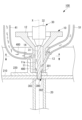
以下、本開示の第1実施形態に係る穴あけ装置100について、図面を参照して説明する。図1は、ストリンガ210およびクリップ220を示す斜視図である。図2は、本開示の第1実施形態に係る穴あけ装置100を示す概略構成図である。図3は、本開示の第1実施形態に係る穴あけ装置100を示す縦断面図である。[First Embodiment]
A
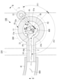
図4は、図3に示す穴あけ装置100のA-A矢視断面図である。図5は、図3に示す穴あけ装置100の被加工部の近傍の部分拡大図である。図3に示す縦断面図は、図4のB-B矢視断面図となっている。図3から図5に示す白抜きの矢印は、空気の流通方向を示している。
FIG. 4 is a cross-sectional view of the
本実施形態の穴あけ装置100は、複数の被加工材を重ねた被加工部に穴あけ加工を行う装置である。図1に示すように、複数の被加工材としては、例えば、航空機に用いられるストリンガ210とクリップ220が挙げられる。
A
ストリンガ210は、航空機の機軸方向に沿って配置される長尺状の部材である。クリップ220は、パネル状に分割された航空機の胴体を円筒状に保持するフレーム(図示略)とストリンガ210とを締結するための部材である。ストリンガ210およびクリップ220は、例えば、アルミニウム合金により形成されている。本実施形態の穴あけ装置100は、ストリンガ210とクリップ220とを重ねた被加工部300に穴あけ加工を行う。被加工部300は、ストリンガ210とクリップ220とを重ねて一体とした部分であり、穴あけ装置100による穴あけ加工によって挿入穴303が形成される部分である。
The
穴あけ加工により被加工部300に形成された貫通穴には、例えばアルミニウム合金により形成されるリベット(図示略)が挿入される。打鋲装置(図示略)は、貫通穴に挿入されたリベットを変形させることにより、ストリンガ210とクリップ220とをリベットを介して締結する。図1には、単一のクリップ220のみが示されているが、ストリンガ210には、長さ方向の複数箇所において複数のクリップ220が取付けられる。
A rivet (not shown) made of, for example, an aluminum alloy is inserted into the through hole formed in the processed
本実施形態では、穴あけ装置100が穴あけ加工を行う対象である被加工材として、アルミニウム合金により形成されるストリンガ210およびクリップ220を採用することとしたが、他の態様であってもよい。例えば、アルミニウム合金以外の金属材料や、金属材料以外の他の材料を採用してもよい。
In the present embodiment, the
図2および図3に示すように、本実施形態の穴あけ装置100は、上部クランプ(第1支持体)10と、下部クランプ(第2支持体)20と、穴あけユニット(穴あけ部)30と、吸引ブロワ40と、吐出ブロワ50と、噴射ブロワ(噴射部)60と、制御部70と、を備える。図2に示すように、制御部70とその他の各部とは、信号線101を介して通信可能なように電気的に接続されている。
As shown in FIGS. 2 and 3, the
図3に示すように、本実施形態の穴あけ装置100は、ストリンガ210およびクリップ220からなる被加工材を重ねた被加工部300に穴あけ加工を行う。穴あけ装置100は、被加工部300の上面(第1面)301側に配置される穴あけユニット30により被加工部300の上面301を切削し、被加工部300の下面(第2面)302まで貫通させる。図3に示す軸線Xは、被加工部300の上面301および下面302に直交する直線である。
As shown in FIG. 3, the
上部クランプ10は、軸線Xに沿って延びる筒状に形成される部材である。上部クランプ10は、制御部70からの制御信号に応じて軸線Xに沿って被加工部300の上面301に接触または離間するように移動する上部移動機構(図示略)を備える。上部クランプ10は、軸線Xに沿って延びる内周面11aを有する筒状に形成された筒部11と、筒部11に連結されて筒部11との連結位置に近付くに連れて外径および内径が縮小する縮径部12とを備える。縮径部12は、クリップ220との干渉を避けるために内外径が縮小しており、軸線Xに沿って延びる筒状となっている。上部クランプ10は、筒部11の下端を被加工部300の上面301に接触させることにより、被加工部300の上面301を支持する。
The
上部クランプ10は、筒部11の内側へ向けて空気(気体)を吐出する吐出ポート(吐出部)13と、穴あけユニット30による穴あけ加工により発生する切削屑400を空気とともに吸引する吸引ポート(吸引部)14を有する。吐出ポート13および吸引ポート14の詳細については、後述する。
The
下部クランプ20は、軸線Xに沿って延びる筒状に形成される部材である。下部クランプ20は、制御部70からの制御信号に応じて軸線Xに沿って被加工部300の下面302に接触または離間するように移動する下部移動機構(図示略)を備える。下部クランプ20は、上端を被加工部300の下面302に接触させることにより、被加工部300の下面302を支持する。
The
穴あけユニット30は、上部クランプ10により上面301が支持され、かつ下部クランプ20により下面302が支持された状態で、被加工部300に穴あけ加工を行う機構である。穴あけユニット30は、穴あけ加工を行うことにより、被加工部300に、例えば、リベットやボルトなどのファスナーを挿入するための挿入穴303を形成する。また、挿入穴303を形成する際に、被加工部300が切削されて切削屑400が発生する。切削屑400は、30mm程度の長さを有する。
The
図3に示すように、穴あけユニット30は、軸線Xに沿って延びるように形成されるドリル31と、軸線Xを中心にドリル31を回転させる駆動機構32と、を有する。駆動機構32は、制御部70から伝達される制御信号に応じて、被加工部300の上面301に接触または離間するように、軸線Xに沿って筒部11および縮径部12の内部でドリル31を移動させる。
As shown in FIG. 3, the
図4に示すように、ドリル31は、軸線Xに直交する断面形状(溝31aを除く外形の断面形状)が円形であるとともに軸線Xに沿って旋回する一対の溝31aが外周面に形成された略棒状に形成される部材である。ドリル31は、被加工部300を切削する際に、駆動機構32により駆動されて軸線X回りに時計回りの回転方向RDに沿って回転する。
As shown in FIG. 4, the
吸引ブロワ40は、吸引ポート14が切削屑400を空気とともに吸引する吸引源となる装置である。吸引ブロワ40は、吸引配管41を介して上部クランプ10の吸引ポート14に接続される。吸引ブロワ40は、フィルター(図示略)を介して空気を吸引して、フィルターを通過後に大気中に吐出することにより、上部クランプ10の筒部11の内部に存在する空気を吸引ポート14へ導く気流を発生させる。吸引ブロワ40は、例えば、3.5m3/minの吸引能力を有する。The
吐出ブロワ50は、吐出ポート13から吐出される空気の気流を発生させる装置である。吐出ブロワ50は、吐出配管51を介して上部クランプ10の吐出ポート13に接続される。吐出ブロワ50は、電磁弁を解放して、圧縮空気を吐出することにより、吐出配管51を介して吐出ポート13へ空気を送風する。
The
噴射ブロワ60は、穴あけユニット30を被加工部300から退避させた退避位置において、穴あけユニット30に付着した被加工部300の切削屑400を除去するための空気(気体)を噴射する装置である。噴射ブロワ60は、図10に示す噴射配管62を介して噴射ポート61に接続されている。
The
図10に示すように、噴射ポート61は、直線状に延びる軸線Y1を中心軸とし、軸線Y1に直交する断面の断面形状が円形となる噴射流路61aを内部に有する。噴射流路61aを流通する空気は、ドリル31の外周面31bの除去位置P4に向けて噴射される。噴射ポート61が空気を吐出する方向は、軸線Y1に沿った方向であり、ドリル31の溝31aのねじれ角αと一致する方向とするのが好ましい。噴射ポート61により除去位置P4へ空気を噴射することにより、吐出ポート13から吐出される空気により除去できずに溝31aに残存した切削屑400を除去することができる。
As shown in FIG. 10, the
制御部70は、上部クランプ10の上部移動機構(図示略)と、下部クランプ20の下部移動機構(図示略)と、穴あけユニット30と、吸引ブロワ40と、吐出ブロワ50と、噴射ブロワ60と、を制御する装置である。制御部70は、例えば、CPU(Central Processing Unit)、RAM(Random Access Memory)、ROM(Read Only Memory)、及びコンピュータ読み取り可能な記憶媒体等から構成されている。そして、各種機能を実現するための一連の処理は、一例として、プログラムの形式で記憶媒体等に記憶されている。制御部70は、CPUがプログラムをRAM等に読み出して、情報の加工・演算処理を実行することにより、各種機能が実現される。
The
次に、上部クランプ10の詳細について説明する。
図3に示すように、上部クランプ10は、吐出ブロワ50により吐出される空気(気体)を筒部11の内側へ向けて吐出する吐出ポート13と、吐出ポート13から吐出された空気をドリル31により被加工部300が切削されて発生した切削屑400とともに吸引する吸引ポート14と、を有する。Next, details of the
As shown in FIG. 3, the
図4および図5に示すように、吐出ポート13は、直線状に延びる軸線Yを中心軸とし、軸線Yに直交する断面の断面形状が円形(例えば、直径が0.5mm以上かつ1.5mm以下)となる吐出流路13aを内部に有する。吐出流路13aを流通する空気は、吐出流路13aと筒部11の内周面11aとが交差する吐出位置P1から、上部クランプ10の筒部11の内周面11aとドリル31の外周面31bとの間に形成される軸線X回りの環状空間S1へ吐出される。吐出ポート13が環状空間S1へ吐出する空気の圧力は、例えば、3kg/cm2以上かつ7kg/cm2以下に設定される。As shown in FIGS. 4 and 5, the
以上の説明において、吐出ポート13の軸線Yに直交する断面形状が円形であるものとしたが、他の態様であってもよい。例えば、楕円形など、円形とは異なる任意の形状としてもよい。
In the above description, the cross-sectional shape of the
環状空間S1は、軸線Xを中心とした半径R1の円筒状の筒部11の内周面11aと、ドリル31の半径R2の外周面31bとの間に形成される空間である。半径R1は、例えば、7.5mm以上かつ9mm以下に設定される。半径R2は、例えば、2.5mm以上かつ3.5mm以下に設定される。
The annular space S1 is a space formed between the inner
図4に示すように、吐出ポート13は、吐出ブロワ50から吐出配管51を介して供給される空気を、吐出位置P1からドリル31の外周面31bの除去位置(所定位置)P2へ向けて吐出する。ここで、ドリル31の外周面31bとは、ドリル31を軸線X回りに回転させた場合に、軸線Xからの距離が最も長くなる位置(最大外径位置)が通過する面をいう。図4においては、軸線Xに対して半径R2となる位置が最大外径位置となる。
As shown in FIG. 4, the
図4は、図3に示す穴あけ装置100のA-A矢視断面図であり、ドリル31を軸線Xに沿って平面視した図となっている。図4に示すように、本実施形態において、吐出ポート13は、ドリル31を軸線Xに沿って平面視した場合に、ドリル31の外周面31bの除去位置P2を通過する外周面31bの接線方向TDと一致する方向に空気を吐出する形態をとることもできる。吐出ポート13は、吐出流路13aの中心軸である軸線Yの延長線が外周面31bと除去位置P2で接するように配置される。すなわち、吐出ポート13は、軸線Yの延長線上に除去位置P2の接線が配置されるように設置される。
FIG. 4 is a cross-sectional view of the
ここでは、吐出ポート13が空気を吐出する方向を、除去位置P2を通過する外周面31bの接線方向TDと一致する方向に設定することとしたが、他の態様であってもよい。例えば、吐出位置P1から吐出ポート13が空気を吐出する方向を、接線方向TDに対して所定の角度範囲(例えば、-5°~5°)で除去位置P2を通過する外周面31bの接線方向TDと一致する方向と異ならせるようにしてもよい。
Here, the direction in which the air is discharged from the
図4に示すように、除去位置P2において、ドリル31が回転する回転方向RDは、吐出位置P1から吐出される空気の吐出方向と一致する接線方向TDと同方向である。穴あけユニット30の駆動機構32は、除去位置P2において、空気の吐出方向と同方向に外周面31bが移動するようにドリル31を回転させる。吐出ポート13から吐出される空気の吐出速度は、ドリル31の回転方向RDに沿った移動速度に対して、10倍以上かつ25倍以下の範囲に設定しても良い。
As shown in FIG. 4, at the removal position P2, the rotation direction RD in which the
図5に示すように、吐出ポート13が空気を吐出する吐出位置P1は、軸線Xに沿って被加工部300の上面301から長さL1だけ離間した位置である。一方、ドリル31の外周面31b上の除去位置P2は、軸線Xに沿って被加工部300の上面301から長さL2だけ離間した位置である。ここで被加工部300とは、ストリンガ210とクリップ220の穴あけ加工を行う部位を指すが、2つの部材を重ねた場合には限らず、3つ以上の被加工材が重なっていても良い。
As shown in FIG. 5, a discharge position P1 where the
図5に示すように、長さL1よりも長さL2の方が短いため、軸線Xに沿った高さ方向において、吐出位置P1よりも除去位置P2の方が低い位置に配置される。そして、吐出ポート13は、吐出位置P1から被加工部300の上面301と交差する方向に空気を吐出する。吐出ポート13が空気を吐出する方向は、軸線Yに沿った方向であり、ドリル31の溝31aのねじれ角αと一致する方向である。ねじれ角αは、ドリル31の軸方向である軸線Xに沿った方向に対する溝31aの傾き角である。ねじれ角αは、例えば、20°以上かつ40°以下に設定される。
As shown in FIG. 5, since the length L2 is shorter than the length L1, in the height direction along the axis X, the removal position P2 is arranged at a lower position than the discharge position P1. The
ここでは、吐出ポート13が空気を吐出する方向を溝31aのねじれ角αと一致する方向に設定することとしたが、他の態様であってもよい。例えば、吐出ポート13が空気を吐出する方向を所定の角度範囲(例えば、α-5°以上かつα+5°以下の角度範囲)で溝31aのねじれ角αと異ならせるようにしてもよい。
Here, the direction in which the air is discharged from the
図4および図5に示すように、吸引ポート14には、ドリル31の中心軸となる軸線Xと交差して直線状に延びる軸線Zを中心軸とし、軸線Zに直交する断面の断面形状が理想的には円形(例えば、直径が10mm以上かつ14mm以下)となる吸引流路14aが形成される。軸線Zは、吸引ポート14の中心軸となる軸線である。吸引流路14aを流通する空気は、環状空間S1から、吸引流路14aと筒部11の内周面11aとが交差する吸引位置P3へ吸引される。吸引位置P3で吸引流路14aへ導かれた空気および切削屑400は、吸引流路14aから吸引配管41を介して吸引ブロワ40へ導かれる。図5に示す吸引位置P3の軸線Xに沿った上面301からの高さは、吸引ポート14がクリップ220と干渉しないように設定されている。
As shown in FIGS. 4 and 5, the
図5に示すように、吸引ポート14の吸引位置P3は、軸線Xに沿って被加工部300の上面301から長さL3だけ離間した位置である。長さL1よりも長さL3の方が長いため、軸線Xに沿った高さ方向において、吐出位置P1よりも吸引位置P3の方が高い位置に配置される。吐出ポート13が吐出位置P1よりも高い位置に配置されているのは、クリップ220との干渉を避けるためである。
As shown in FIG. 5, the suction position P3 of the
図4に示すように、吸引ポート14が空気とともに切削屑400を吸引する吸引位置P3は、軸線X回りの周方向において、除去位置P2から角度θ2を空けて配置されている。角度θ2は、例えば、90°以上かつ180°以下に設定するのが好ましい。すなわち、吸引位置P3は、軸線X回りの周方向において、除去位置P2から半周の範囲内に配置するのが好ましい。
As shown in FIG. 4, a suction position P3 where the
図4に示すように、吐出ポート13が空気を吐出する吐出位置P1は、軸線X回りの周方向において、除去位置P2から角度θ1を空けて配置されている。角度θ1と角度θ2とを加算した角度は、例えば、90°以上かつ270°以下に設定するのが好ましい。
As shown in FIG. 4, the discharge position P1 at which the
次に、本実施形態に係る穴あけ装置100が実行する穴あけ方法について、図面を参照して説明する。図6は、本実施形態に係る穴あけ装置100が実行する穴あけ方法を示すフローチャートである。図7は、支持工程を実行する前の穴あけ装置100を示す縦断面図である。図8は、支持工程を実行した後の穴あけ装置100を示す縦断面図である。図9は、穴あけ工程における穴あけ装置100を示す縦断面図である。
Next, a drilling method executed by the
ステップS101(支持工程)においては、上部クランプ10の上部移動機構(図示略)が制御部70から伝達される制御信号により制御され、筒部11の下端が被加工部300の上面301に近接する方向に移動する。上部クランプ10は、筒部11の下端が被加工部300の上面301に接触する位置まで移動し、被加工部300の上面301を支持する。
In step S101 (supporting step), an upper moving mechanism (not shown) of the
また、ステップS101においては、下部クランプ20の下部移動機構(図示略)が制御部70から伝達される制御信号により制御され、下部クランプ20の上端が被加工部300の下面302に近接する方向に移動する。下部クランプ20は、上端が被加工部300の下面302に接触する位置まで移動し、被加工部300の下面302を支持する。ステップS101が実行されると、穴あけ装置100は、図7に示す状態から図8に示す状態となる。
Further, in step S101, a lower movement mechanism (not shown) of the
ステップS102(穴あけ工程)においては、上部クランプ10および下部クランプ20により被加工部300が支持された状態で、穴あけユニット30のドリル31により被加工部300に穴あけ加工が実行される。穴あけユニット30の駆動機構32は、制御部70から伝達される制御信号により制御され、図8に実線で示す退避位置から図8に破線で示す軸線X上の位置に移動する。
In step S102 (drilling step), the
また、ステップS102においては、穴あけユニット30の駆動機構32が制御部70から伝達される制御信号により制御される。穴あけユニット30は、軸線Xに沿って被加工部300の上面301に近接する方向(図8における下向き方向)に向けて上部クランプ10の縮径部12および筒部11の内部を移動し、図9に示す状態となる。駆動機構32は、被加工部300に挿入穴303が形成されるまでは、軸線Xを中心にドリル31を回転方向RDに沿って回転させる。
Further, in step S<b>102 , the
穴あけユニット30が更に被加工部300の上面301に近接する方向に移動すると、ドリル31の先端が被加工部300の上面301に接触し、ドリル31による穴あけ加工が開始される。ドリル31が被加工部300に接触しながら軸線Xに沿って更に下向きに移動すると、図1および図5に示すように、被加工部300に挿入穴303が形成された状態となる。
When the
また、ステップS102においては、吐出ブロワ50が制御部70から伝達される制御信号により制御される。吐出ブロワ50は、吐出配管51を介して吐出ポート13に空気を供給する。吐出ポート13は、被加工部300の穴あけ加工により発生する切削屑400をドリル31の溝31aから除去するための空気をドリル31の外周面31bの除去位置P2へ向けて吐出する。
Further, in step S102, the
また、ステップS102においては、吸引ブロワ40が制御部70から伝達される制御信号により制御される。吸引ブロワ40は、吐出配管51から空気を吸引して吐出することにより、環状空間S1から吸引ポート14へ切削屑400を空気とともに吸引する。
Further, in step S102, the
ステップS103(退避工程)においては、被加工部300に挿入穴303が形成されたことに応じて、穴あけユニット30を、ドリル31が挿入穴303に挿入された位置から軸線Xに沿って上方に移動させ、被加工部300から退避させる。穴あけユニット30は、図8に破線で示す軸線X上の位置に移動した後、図8に実線で示す退避位置へ移動する。
In step S103 (retreat step), in response to the formation of the
ステップS104(噴射工程)においては、穴あけユニット30を退避位置に退避させた状態で、噴射ポート61からドリル31の外周面31bに向けてドリル31の溝31aから切削屑400を除去するための空気が噴射される。なお、ステップS104の噴射工程を実行しない態様としてもよい。ステップS104は、切削屑がトリルに巻き付いたまま退避位置に戻った場合に、切削屑を除去するのに有効な手段であるため、S104を省略してもドリル31が筒部11内部にある時の切削屑除去は可能である。以上の処理により被加工部300に挿入穴303を形成する穴あけ加工が実行される。
In step S104 (injection process), air for removing
以上説明した本実施形態の穴あけ装置100が奏する作用及び効果について説明する。
本実施形態の穴あけ装置100によれば、ストリンガ210およびクリップ220を重ねた被加工部300の上面301が上部クランプ10により支持され、被加工部300の下面302が下部クランプ20により支持された状態で、外周面31bに溝31aが形成されたドリル31を軸線X回りに回転させることにより、被加工部300に穴あけ加工が行われる。ドリル31により切削される被加工部300から切削屑400が発生し、切削屑400がドリル31の溝31aに沿って成長する。切削屑400が所定長さ以上に成長すると切削屑400の端部がドリル31の外周面31bの外側へ突出した状態となる。The operation and effects of the
According to the
本実施形態の穴あけ装置100によれば、吐出ポート13から、穴あけユニット30による被加工部300の穴あけ加工により発生する切削屑400をドリル31の溝31aから除去するための空気がドリル31の外周面31bの除去位置P2へ向けて吐出される。吐出ポート13は、ドリル31を軸線Xに沿って平面視した場合に除去位置P2を通過する外周面31bの接線方向TDと一致する方向に空気を吐出する。そのため、吐出ポート13から吐出される空気が、ドリル31の外周面31bの外側へ突出した切削屑400の端部に吹き付けられる。これにより、切削屑400の端部がドリル31の外周面31bから引き離されるとともに切削屑400がドリル31の溝31aから離脱する。ドリル31の溝31aから離脱した切削屑400は、吐出ポート13から吐出された空気とともに吸引ポート14により吸引される。
According to the
このように、本実施形態の穴あけ装置100によれば、穴あけユニット30が有するドリル31の溝31aに付着する切削屑400が吐出ポート13から吐出される空気により除去されるため、ドリル31の溝31aに切削屑400が付着したまま成長して切削屑400によりストリンガ210およびクリップ220が傷つくことを防止することができる。
As described above, according to the
本実施形態の穴あけ装置100によれば、軸線X回りの周方向において、吸引位置P3が吐出ポート13から吐出された空気が通過する除去位置P2から半周の範囲内に配置されている。そのため、吐出ポート13から吐出された空気は、軸線X回りに周回することなく、吐出ポート13から吐出された速度成分を保持したまま切削屑400とともに吸引ポート14へ導かれる。これにより、上部クランプ10とドリル31の外周面31bとの間に形成される環状空間S1において、切削屑400を軸線X回りに周回させて被加工部300を傷つけることなく、除去位置P2から吸引位置P3へ向けて切削屑400を導くことができる。
According to the
本実施形態の穴あけ装置100によれば、吐出位置P1から上面301と交差する方向に空気が吐出されるため、ドリル31の溝31aから離脱した切削屑400が上面301に向けて導かれる。ドリル31の溝31aから離脱した切削屑400が上面301から離れる方向に導かれないため、切削屑400が吸引ポート14へ導かれずに上部クランプ10の外部へ放出されることを抑制することができる。
According to the
本実施形態の穴あけ装置100によれば、ドリル31の溝31aのねじれ角αと一致する方向に空気が吐出される。そのため、切削屑400の端部をドリル31の溝31aのねじれ角αと一致する方向に沿って外周面31bから引き離し、切削屑400をドリル31の溝31aからより確実に離脱させることができる。
According to the
本実施形態の穴あけ装置100によれば、吐出ポート13から吐出された空気が通過する除去位置P2において、空気の吐出方向と同方向にドリル31の外周面31bが移動する。そのため、ドリル31の溝31aに付着した切削屑400に対して常に溝31aから離脱する方向の力を与え、切削屑400の溝31aからの離脱を促進することができる。また、切削屑400に対してドリル31により除去位置P2から吸引ポート14へ向けた速度成分が与えられるため、切削屑400をより確実に吸引ポート14へ導くことができる。
According to the
本実施形態の穴あけ装置100によれば、穴あけユニット30を被加工部300から退避させて退避位置において、ドリル31の外周面31bに向けて空気を噴射することにより、吐出ポート13から吐出された空気により除去されずに溝31aに残存した切削屑400を、次の穴あけ加工を実行する前に除去することができる。
According to the
〔第2実施形態〕
次に、本開示の第2実施形態に係る穴あけ装置100Aについて図面を参照して説明する。図11は、本実施形態に係る穴あけ装置100Aの被加工部300の近傍の部分拡大図である。本実施形態は、第1実施形態の変形例であり、以下で特に説明する場合を除き、第1実施形態と同様であるものとし、以下での説明を省略する。[Second embodiment]
Next, a
第1実施形態の穴あけ装置100の吐出ポート13は、吐出位置P1から被加工部300の上面301と交差する方向に空気を吐出するものであった。それに対して、本実施形態の穴あけ装置100Aの吐出ポート13Aは、吐出位置P1Aから被加工部300の上面301と平行な方向に空気を吐出するものである。
The
図11に示すように、本実施形態の穴あけ装置100Aの上部クランプ10Aは、吐出ポート13Aを有する。吐出ポート13Aは、直線状に延びる軸線Y1を中心軸とし、軸線Y1に直交する断面の断面形状が円形(例えば、直径が0.5mm以上かつ1.5mm以下)となる吐出流路13Aaを内部に有する。
As shown in FIG. 11, the
吐出流路13Aaを流通する空気は、吐出流路13Aaと筒部11Aの内周面11Aaとが交差する吐出位置P1Aから、上部クランプ10Aの筒部11Aの内周面11Aaとドリル31の外周面31bとの間に形成される軸線X回りの環状空間S1へ吐出される。吐出ポート13Aが環状空間S1へ吐出する空気の圧力は、例えば、3kg/cm2以上かつ7kg/cm2以下に設定される。The air flowing through the discharge channel 13Aa is directed from the discharge position P1A where the discharge channel 13Aa and the inner peripheral surface 11Aa of the
図11に示すように、吐出ポート13Aは、吐出ブロワ50から吐出配管51を介して供給される空気を、吐出位置P1からドリル31の外周面31bの除去位置(所定位置)P2Aへ向けて吐出する。吐出ポート13Aは、吐出位置P1から被加工部300の上面301と平行な方向に空気を吐出する。
As shown in FIG. 11, the
本実施形態の穴あけ装置100Aによれば、吐出位置P1Aから上面301と平行な方向に空気が吐出されるため、ドリル31の溝31aから離脱した切削屑400が上面301と平行な方向に導かれる。ドリル31の溝31aから離脱した切削屑400が上面301に向けて直接的に導かれないため、切削屑400が上面301に直接的に導かれて上面301を傷つけることを防止することができる。
According to the
〔第3実施形態〕
次に、本開示の第3実施形態に係る穴あけ装置100Bについて図面を参照して説明する。図12は、本実施形態に係る穴あけ装置100Bの被加工部300の近傍の部分拡大図である。本実施形態は、第1実施形態の変形例であり、以下で特に説明する場合を除き、第1実施形態と同様であるものとし、以下での説明を省略する。[Third Embodiment]
Next, a
第1実施形態の穴あけ装置100の上部クランプ10は、単一の吐出ポート13を備えるものであった。それに対して、本実施形態の穴あけ装置100Bの上部クランプ10Bは、吐出ポート13に加えて吐出ポート15を備える。
The
図12に示すように、本実施形態の穴あけ装置100Bの上部クランプ10Bは、吐出ポート15を有する。吐出ポート15は、直線状に延びる軸線Z1を中心軸とし、軸線Z1に直交する断面の断面形状が円形(例えば、直径が0.5mm以上かつ1.5mm以下)となる吐出流路15aを内部に有する。
As shown in FIG. 12, the
吐出流路15aを流通する空気は、吐出流路15aと筒部11Bの内周面11Baとが交差する吐出位置P5から、上部クランプ10Bの筒部11Bの内周面11Baとドリル31の外周面31bとの間に形成される軸線X回りの環状空間S1へ吐出される。吐出ポート15が環状空間S1へ吐出する空気の圧力は、例えば、3kg/cm2以上かつ7kg/cm2以下に設定される。The air flowing through the
図12に示すように、吐出ポート15は、吐出ブロワ50から吐出配管52を介して供給される空気を、吐出位置P5からドリル31の外周面31bの除去位置(所定位置)P6へ向けて吐出する。吐出ポート15は、吐出位置P1から被加工部300の上面301と平行な方向に空気を吐出する。
As shown in FIG. 12, the
本実施形態の穴あけ装置100Bによれば、吐出ポート13と吐出ポート15の双方からドリル31の外周面31bへ空気が吐出される。そのため、単一の吐出ポートから空気を吐出する場合に比べ、ドリル31の溝31aに付着した切削屑400を確実に除去することができる。
According to the
また、本実施形態の穴あけ装置100Bによれば、吐出位置P5から上面301と平行な方向に空気が吐出されるため、ドリル31の溝31aから離脱した切削屑400が上面301と平行な方向に導かれる。ドリル31の溝31aから離脱した切削屑400が上面301に向けて直接的に導かれないため、切削屑400が上面301に直接的に導かれて上面301を傷つけることを防止することができる。
Further, according to the
また、本実施形態の穴あけ装置100Bによれば、吐出ポート13から上面301に向けて吐出される空気により切削屑400が上面301へ導かれても、吐出位置P5から上面301と平行な方向に吐出される空気により切削屑400が上面301へ衝突することを防止することができる。
Further, according to the
本実施形態の吐出ポート13は、第1実施形態と同様に、吐出位置P1から被加工部300の上面301と交差する方向に空気を吐出するものであるが、他の態様であってもよい。例えば、第2実施形態の吐出ポート13Aと同様に、吐出位置P1から被加工部300の上面301と平行な方向に空気を吐出するものとしてもよい。
The
以上説明した実施形態に記載の穴あけ装置(100)は、例えば以下のように把握される。
本開示に係る穴あけ装置(100)は、複数の被加工材(210,220)を重ねた被加工部(300)に穴あけ加工を行い、軸線(X)に沿って延びる筒状に形成されて前記被加工部の第1面(301)を支持する第1支持体(10)と、前記軸線に沿って延びる筒状に形成されて前記被加工部の第2面(302)を支持する第2支持体(20)と、前記被加工部に穴あけ加工を行う穴あけ部(30)と、を備え、前記穴あけ部は、前記軸線に直交する断面形状が円形であるとともに前記軸線に沿って旋回する溝(31a)が外周面に形成されたドリル(31)と、前記軸線を中心に前記ドリルを回転させるとともに前記被加工部の前記第1面に接触または離間するように前記ドリルを前記軸線に沿って前記第1支持体(10)の内部を移動させる駆動機構(32)と、を有し、前記第1支持体は、前記穴あけ部による前記被加工部の穴あけ加工により発生する切削屑を前記ドリルの前記溝から除去するための気体を前記ドリルの外周面の所定位置へ向けて吐出する吐出部(13)と、前記切削屑を気体とともに吸引する吸引部(14)と、を有し、前記吐出部は、前記ドリルを前記軸線に沿って平面視した場合に前記所定位置を通過する前記外周面の接線方向と一致する方向に気体を吐出する。The punching device (100) described in the embodiments described above can be grasped, for example, as follows.
A drilling device (100) according to the present disclosure drills a workpiece (300) in which a plurality of workpieces (210, 220) are stacked, and is formed into a cylindrical shape extending along an axis (X). A first support (10) supporting a first surface (301) of the part to be processed, and a second support (10) formed in a cylindrical shape extending along the axis and supporting a second surface (302) of the part to be processed. 2 a support body (20) and a drilling part (30) for drilling the part to be processed, the drilling part having a circular cross-sectional shape orthogonal to the axis and rotating along the axis a drill (31) having a groove (31a) formed on its outer peripheral surface, and rotating the drill around the axis and moving the drill so as to come into contact with or separate from the first surface of the workpiece; and a drive mechanism (32) for moving the inside of the first support (10) along the a discharge part (13) for discharging gas toward a predetermined position on the outer peripheral surface of the drill for removing from the groove of the drill; and a suction part (14) for sucking the chips together with the gas. The discharge portion discharges gas in a direction that coincides with a tangential direction of the outer peripheral surface passing through the predetermined position when the drill is viewed from above along the axis.
本開示の一態様に係る穴あけ装置によれば、複数の被加工材を重ねた被加工部の第1面が第1支持体により支持され、被加工部の第2面が第2支持体により支持された状態で、外周面に溝が形成されたドリルを軸線回りに回転させることにより、被加工部に穴あけ加工が行われる。ドリルにより切削される被加工部から切削屑が発生し、切削屑がドリルの溝に沿って成長する。切削屑が所定長さ以上に成長すると切削屑の端部がドリルの外周面の外側へ突出した状態となる。 According to the drilling device according to one aspect of the present disclosure, the first surface of the processed portion in which the plurality of processed materials are stacked is supported by the first support, and the second surface of the processed portion is supported by the second support. A drill having grooves formed on its outer peripheral surface is rotated around its axis while being supported, so that a drilling process is performed on the part to be processed. Chips are generated from the workpiece cut by the drill, and the chips grow along the flutes of the drill. When the chips grow to a predetermined length or longer, the ends of the chips protrude outside the outer peripheral surface of the drill.
本開示の一態様に係る穴あけ装置によれば、吐出部から、穴あけ部による被加工部の穴あけ加工により発生する切削屑をドリルの溝から除去するための気体がドリルの外周面の所定位置へ向けて吐出される。吐出部は、ドリルを軸線に沿って平面視した場合に所定位置を通過する外周面の接線方向と一致する方向に気体を吐出する。そのため、吐出部から吐出される気体が、ドリルの外周面の外側へ突出した切削屑の端部に吹き付けられる。これにより、切削屑の端部がドリルの外周面から引き離されるとともに切削屑がドリルの溝から離脱する。ドリルの溝から離脱した切削屑は、吐出部から吐出された気体とともに吸引部により吸引される。 According to the drilling device according to one aspect of the present disclosure, the gas for removing cutting chips generated by the drilling process of the workpiece by the drilling unit from the discharge unit is delivered to a predetermined position on the outer peripheral surface of the drill. It is discharged towards. The discharge part discharges gas in a direction that coincides with a tangential direction of the outer peripheral surface that passes through a predetermined position when the drill is viewed from above along the axis. Therefore, the gas discharged from the discharge part is blown to the end of the chips projecting outside the outer peripheral surface of the drill. As a result, the ends of the chips are pulled away from the outer peripheral surface of the drill and the chips are separated from the flutes of the drill. Chips separated from the groove of the drill are sucked by the suction part together with the gas discharged from the discharge part.
このように、本開示の一態様に係る穴あけ装置によれば、穴あけ部が有するドリルの溝部に付着する切削屑が吐出部から吐出される気体により除去されるため、ドリルの溝に切削屑が付着したまま成長して切削屑により被加工材が傷つくことを防止することができる。 As described above, according to the drilling device according to one aspect of the present disclosure, the cutting chips adhering to the groove of the drill of the drilling section are removed by the gas discharged from the discharge section, so that the cutting chips remain in the groove of the drill. It is possible to prevent the workpiece from being damaged by the cutting chips that grow while adhering to them.
本開示の一態様に係る穴あけ装置において、前記軸線回りの周方向において、前記吸引部が前記切削屑を吸引する吸引位置は、前記所定位置から半周の範囲内に配置されている構成が好ましい。
本構成の穴あけ装置によれば、軸線回りの周方向において、吸引位置が吐出部から吐出された気体が通過する所定位置から半周の範囲内に配置されている。そのため、吐出部から吐出された気体は、軸線回りに周回することなく、吐出部から吐出された速度成分を保持したまま切削屑とともに吸引部へ導かれる。これにより、第1支持体とドリルの外周面との間に形成される空間において、切削屑を軸線回りに周回させて被加工部を傷つけることなく、所定位置から吸引位置へ向けて切削屑を導くことができる。In the drilling device according to an aspect of the present disclosure, it is preferable that a suction position where the suction unit suctions the cutting waste is arranged within a range of half a circumference from the predetermined position in the circumferential direction around the axis.
According to the punching device of this configuration, in the circumferential direction around the axis, the suction position is arranged within a range of half the circumference from the predetermined position through which the gas discharged from the discharge part passes. Therefore, the gas discharged from the discharge part is guided to the suction part together with the chips while maintaining the velocity component discharged from the discharge part without revolving around the axis. As a result, in the space formed between the first support and the outer peripheral surface of the drill, the cutting chips are circulated around the axis so that the cutting chips are removed from the predetermined position toward the suction position without damaging the workpiece. can lead.
本開示の一態様に係る穴あけ装置において、前記吐出部が前記気体を吐出する吐出位置は、前記軸線に沿って前記第1面から離間した位置であり、前記吐出部は、前記吐出位置から前記第1面と交差する方向に気体を吐出する構成が好ましい。
本構成の穴あけ装置によれば、吐出位置から第1面と交差する方向に気体が吐出されるため、ドリルの溝から離脱した切削屑が第1面に向けて導かれる。ドリルの溝から離脱した切削屑が第1面から離れる方向に導かれないため、切削屑が吸引部へ導かれずに第1支持体の外部へ放出されることを抑制することができる。In the drilling device according to one aspect of the present disclosure, a discharge position where the discharge part discharges the gas is a position separated from the first surface along the axis, and the discharge part is located from the discharge position to the A configuration in which the gas is discharged in a direction intersecting with the first surface is preferable.
According to the drilling device of this configuration, the gas is discharged from the discharge position in the direction intersecting with the first surface, so that the chips released from the groove of the drill are guided toward the first surface. Since the chips separated from the groove of the drill are not guided away from the first surface, it is possible to prevent the chips from being discharged to the outside of the first support without being guided to the suction portion.
上記構成の穴あけ装置において、前記吐出部は、前記ドリルの前記溝のねじれ角と一致する方向に気体を吐出する構成が好ましい。
本構成の穴あけ装置によれば、ドリルの溝のねじれ角と一致する方向に気体が吐出されるため、切削屑の端部をドリルの溝のねじれ角と一致する方向に沿って外周面から引き離し、切削屑をドリルの溝からより確実に離脱させることができる。In the drilling device configured as described above, it is preferable that the discharge section discharges gas in a direction that matches the twist angle of the groove of the drill.
According to the drilling device of this configuration, since the gas is discharged in the direction that matches the helix angle of the flute of the drill, the ends of the chips are separated from the outer peripheral surface along the direction that matches the helix angle of the flute of the drill. , cutting chips can be more reliably separated from the flute of the drill.
本開示の一態様に係る穴あけ装置において、前記吐出部は、前記吐出位置から前記第1面と平行な方向に気体を吐出する構成が好ましい。
本構成の穴あけ装置によれば、吐出位置から第1面と平行な方向に気体が吐出されるため、ドリルの溝から離脱した切削屑が第1面と平行な方向に導かれる。ドリルの溝から離脱した切削屑が第1面に向けて直接的に導かれないため、切削屑が第1面に直接的に導かれて第1面を傷つけることを防止することができる。In the punching device according to the aspect of the present disclosure, it is preferable that the discharge section discharges gas from the discharge position in a direction parallel to the first surface.
According to the drilling device of this configuration, the gas is discharged from the discharge position in the direction parallel to the first surface, so that the chips released from the groove of the drill are guided in the direction parallel to the first surface. Since the chips separated from the groove of the drill are not directly guided toward the first surface, it is possible to prevent the chips from being directly guided to the first surface and damaging the first surface.
本開示の一態様に係る穴あけ装置において、前記駆動機構は、前記所定位置において気体の吐出方向と同方向に前記外周面が移動するように前記ドリルを回転させる構成とするのが好ましい。
本構成の穴あけ装置によれば、吐出部から吐出された気体が通過する所定位置において、気体の吐出方向と同方向にドリルの外周面が移動する。そのため、ドリルの溝に付着した切削屑に対して常に溝部から離脱する方向の力を与え、切削屑の溝からの離脱を促進することができる。また、切削屑に対してドリルにより所定位置から吸引部へ向けた速度成分が与えられるため、切削溝をより確実に吸引部へ導くことができる。In the drilling device according to the aspect of the present disclosure, it is preferable that the drive mechanism rotates the drill so that the outer peripheral surface moves in the same direction as the gas discharge direction at the predetermined position.
According to the drilling device of this configuration, the outer peripheral surface of the drill moves in the same direction as the gas discharge direction at the predetermined position through which the gas discharged from the discharge part passes. Therefore, it is possible to always apply a force in the direction of detachment from the groove portion to the chips adhering to the flute of the drill, and to promote the detachment of the chips from the flute. In addition, since the drill imparts a velocity component directed from a predetermined position to the suction portion to the chips, it is possible to more reliably guide the cutting groove to the suction portion.
本開示の一態様に係る穴あけ装置において、前記穴あけ部を前記被加工部から退避させた退避位置において、前記ドリルの外周面に向けて前記ドリルの前記溝から前記切削屑を除去するための気体を噴射する噴射部を備える構成とするのが好ましい。
本構成の穴あけ装置によれば、穴あけ部を被加工部から退避させて退避位置において、ドリルの外周面に向けて気体を噴射することにより、吐出部から吐出された気体により除去されずに溝に付着した切削屑を、次の穴あけ加工を実行する前に除去することができる。In the drilling device according to one aspect of the present disclosure, gas for removing the chips from the groove of the drill toward the outer peripheral surface of the drill at a retracted position in which the drilling part is retracted from the workpiece. It is preferable to have a configuration provided with an injection portion for injecting the.
According to the drilling apparatus of this configuration, the drilling portion is retracted from the workpiece and, at the retracted position, the gas is jetted toward the outer peripheral surface of the drill. Chips adhering to the can be removed before performing the next drilling operation.
以上説明した実施形態に記載の穴あけ方法は、例えば以下のように把握される。
本開示の一態様に係る穴あけ方法は、複数の被加工材を重ねた被加工部に穴あけ加工を行い、軸線に沿って延びる筒状に形成される第1支持体により前記被加工部の第1面を支持し、前記軸線に沿って延びる筒状に形成される第2支持体により前記被加工部の第2面を支持する支持工程(S101)と、前記第1支持体および前記第2支持体により前記被加工部が支持された状態で、前記軸線に直交する断面形状が円形であるとともに前記軸線に沿って旋回する溝が外周面に形成されたドリルにより、前記被加工部に穴あけ加工を行う穴あけ工程(S102)と、を備え、前記穴あけ工程は、前記軸線を中心に前記ドリルを回転させるとともに、前記被加工部の前記第1面に接触するように前記ドリルを前記軸線に沿って前記第1支持体の内部を移動させ、前記被加工部の穴あけ加工により発生する切削屑を前記ドリルの前記溝から除去するための気体を、前記第1支持体が有する吐出部から前記ドリルの外周面の所定位置へ向けて吐出し、前記第1支持体が有する吸引部へ前記切削屑を気体とともに吸引し、前記吐出部は、前記ドリルを前記軸線に沿って平面視した場合に前記所定位置を通過する前記外周面の接線方向と一致する方向に気体を吐出する。For example, the drilling method described in the embodiments described above can be grasped as follows.
A drilling method according to an aspect of the present disclosure performs a drilling process on a workpiece in which a plurality of workpieces are stacked, and a first support body formed in a cylindrical shape extending along an axis line is used to form a first support of the workpiece. a supporting step (S101) of supporting a second surface of the processed portion by a cylindrical second support that supports one surface and extends along the axis; In a state in which the work piece is supported by a support, a drill having a circular cross-sectional shape perpendicular to the axis line and having a groove formed on the outer peripheral surface thereof that rotates along the axis line is used to drill a hole in the work piece. and a drilling step (S102) of performing machining, wherein the drilling step rotates the drill about the axis and moves the drill along the axis so as to contact the first surface of the workpiece. gas for removing chips generated by drilling of the workpiece from the groove of the drill from the discharge part of the first support. The drill is discharged toward a predetermined position on the outer peripheral surface of the drill, and the suction portion of the first support sucks the chips together with the gas. The gas is discharged in a direction coinciding with a tangential direction of the outer peripheral surface passing through the predetermined position.
本開示の一態様に係る穴あけ方法によれば、複数の被加工材を重ねた被加工部の第1面が第1支持体により支持され、被加工部の第2面が第2支持体により支持された状態で、外周面に溝が形成されたドリルを軸線回りに回転させることにより、被加工部に穴あけ加工が行われる。ドリルにより切削される被加工部から切削屑が発生し、切削屑がドリルの溝に沿って成長する。切削屑が所定長さ以上に成長すると切削屑の端部がドリルの外周面の外側へ突出した状態となる。 According to the drilling method according to one aspect of the present disclosure, the first surface of the portion to be processed in which a plurality of workpieces are stacked is supported by the first support, and the second surface of the portion to be processed is supported by the second support. By rotating the drill having grooves on the outer peripheral surface while being supported, the drilling process is performed on the part to be processed. Chips are generated from the workpiece cut by the drill, and the chips grow along the flutes of the drill. When the chips grow to a predetermined length or longer, the ends of the chips protrude outside the outer peripheral surface of the drill.
本開示の一態様に係る穴あけ方法によれば、吐出部から、穴あけ部による被加工部の穴あけ加工により発生する切削屑をドリルの溝から除去するための気体がドリルの外周面の所定位置へ向けて吐出される。吐出部は、ドリルを軸線に沿って平面視した場合に所定位置を通過する外周面の接線方向と一致する方向に気体を吐出する。そのため、吐出部から吐出される気体が、ドリルの外周面の外側へ突出した切削屑の端部に吹き付けられる。これにより、切削屑の端部がドリルの外周面から引き離されるとともに切削屑がドリルの溝から離脱する。ドリルの溝から離脱した切削屑は、吐出部から吐出された気体とともに吸引部により吸引される。 According to the drilling method according to one aspect of the present disclosure, the gas for removing chips generated by the drilling of the workpiece by the drilling unit from the groove of the drill is discharged from the discharge unit to a predetermined position on the outer peripheral surface of the drill. It is discharged towards. The discharge part discharges gas in a direction that coincides with a tangential direction of the outer peripheral surface that passes through a predetermined position when the drill is viewed from above along the axis. Therefore, the gas discharged from the discharge part is blown to the end of the chips projecting outside the outer peripheral surface of the drill. As a result, the ends of the chips are pulled away from the outer peripheral surface of the drill and the chips are separated from the flutes of the drill. Chips separated from the groove of the drill are sucked by the suction part together with the gas discharged from the discharge part.
このように、本開示の一態様に係る穴あけ方法によれば、ドリルの溝部に付着する切削屑が吐出部から吐出される気体により除去されるため、ドリルの溝に切削屑が付着したまま成長して切削屑により被加工材が傷つくことを防止することができる。 As described above, according to the drilling method according to one aspect of the present disclosure, since the cutting debris adhering to the groove of the drill is removed by the gas discharged from the discharge part, the cutting debris adheres to the groove of the drill and grows. As a result, it is possible to prevent the workpiece from being damaged by cutting waste.
本開示の一態様に係る穴あけ方法において、前記軸線回りの周方向において、前記吸引部が前記切削屑を吸引する吸引位置は、前記所定位置から半周の範囲内に配置されている構成が好ましい。
本構成の穴あけ方法によれば、軸線回りの周方向において、吸引位置が吐出部から吐出された気体が通過する所定位置から半周の範囲内に配置されている。そのため、吐出部から吐出された気体は、軸線回りに周回することなく、吐出部から吐出された速度成分を保持したまま切削屑とともに吸引部へ導かれる。これにより、第1支持体とドリルの外周面との間に形成される空間において、切削屑を軸線回りに周回させて被加工部を傷つけることなく、所定位置から吸引位置へ向けて切削屑を導くことができる。In the drilling method according to an aspect of the present disclosure, it is preferable that a suction position at which the suction portion suctions the cutting waste is arranged within a range of half a circumference from the predetermined position in the circumferential direction around the axis.
According to the drilling method of this configuration, in the circumferential direction around the axis, the suction position is arranged within a range of half the circumference from the predetermined position through which the gas discharged from the discharge part passes. Therefore, the gas discharged from the discharge part is guided to the suction part together with the chips while maintaining the velocity component discharged from the discharge part without revolving around the axis. As a result, in the space formed between the first support and the outer peripheral surface of the drill, the cutting chips are circulated around the axis so that the cutting chips are removed from the predetermined position toward the suction position without damaging the workpiece. can lead.
本開示の一態様に係る穴あけ方法において、前記吐出部が前記気体を吐出する吐出位置は、前記軸線に沿って前記第1面から離間した位置であり、前記穴あけ工程は、前記吐出位置から前記第1面と交差する方向に気体を吐出する構成が好ましい。
本構成の穴あけ方法によれば、吐出位置から第1面と交差する方向に気体が吐出されるため、ドリルの溝から離脱した切削屑が第1面に向けて導かれる。ドリルの溝から離脱した切削屑が第1面から離れる方向に導かれないため、切削屑が吸引部へ導かれずに第1支持体の外部へ放出されることを抑制することができる。In the drilling method according to an aspect of the present disclosure, the ejection position at which the ejection part ejects the gas is a position separated from the first surface along the axis, and the drilling step is performed from the ejection position to the A configuration in which the gas is discharged in a direction intersecting with the first surface is preferable.
According to the drilling method of this configuration, the gas is discharged from the discharge position in the direction intersecting with the first surface, so that the chips released from the groove of the drill are guided toward the first surface. Since the chips separated from the groove of the drill are not guided away from the first surface, it is possible to prevent the chips from being discharged to the outside of the first support without being guided to the suction portion.
本開示の一態様に係る穴あけ方法において、前記穴あけ工程は、前記吐出部から前記ドリルの前記溝のねじれ角と一致する方向に気体を吐出する構成が好ましい。
本構成の穴あけ方法によれば、ドリルの溝のねじれ角と一致する方向に気体が吐出されるため、切削屑の端部をドリルの溝のねじれ角と一致する方向に沿って外周面から引き離し、切削屑をドリルの溝からより確実に離脱させることができる。In the drilling method according to an aspect of the present disclosure, it is preferable that the drilling step discharges gas from the discharge part in a direction that matches the twist angle of the groove of the drill.
According to the drilling method of this configuration, since the gas is discharged in the direction that matches the helix angle of the flute of the drill, the end of the chips is separated from the outer peripheral surface along the direction that matches the helix angle of the flute of the drill. , cutting chips can be more reliably separated from the flute of the drill.
本開示の一態様に係る穴あけ方法において、前記穴あけ工程は、前記吐出位置から前記第1面と平行な方向に気体を吐出する構成が好ましい。
本構成の穴あけ方法によれば、吐出位置から第1面と平行な方向に気体が吐出されるため、ドリルの溝から離脱した切削屑が第1面と平行な方向に導かれる。ドリルの溝から離脱した切削屑が第1面に向けて直接的に導かれないため、切削屑が第1面に直接的に導かれて第1面を傷つけることを防止することができる。In the drilling method according to an aspect of the present disclosure, it is preferable that the drilling step discharges gas from the discharge position in a direction parallel to the first surface.
According to the drilling method of this configuration, the gas is discharged from the discharge position in the direction parallel to the first surface, so that the chips released from the groove of the drill are guided in the direction parallel to the first surface. Since the chips separated from the groove of the drill are not directly guided toward the first surface, it is possible to prevent the chips from being directly guided to the first surface and damaging the first surface.
本開示の一態様に係る穴あけ方法において、前記穴あけ工程は、前記所定位置において気体の吐出方向と同方向に前記外周面が移動するように前記ドリルを回転させる構成が好ましい。
本構成の穴あけ方法によれば、吐出部から吐出された気体が通過する所定位置において、気体の吐出方向と同方向にドリルの外周面が移動する。そのため、ドリルの溝に付着した切削屑に対して常に溝部から離脱する方向の力を与え、切削屑の溝からの離脱を促進することができる。また、切削屑に対してドリルにより所定位置から吸引部へ向けた速度成分が与えられるため、切削溝をより確実に吸引部へ導くことができる。In the drilling method according to an aspect of the present disclosure, it is preferable that the drilling step rotates the drill so that the outer peripheral surface moves in the same direction as the gas discharge direction at the predetermined position.
According to the drilling method of this configuration, the outer peripheral surface of the drill moves in the same direction as the gas discharge direction at the predetermined position through which the gas discharged from the discharge part passes. Therefore, it is possible to always apply a force in the direction of detachment from the groove portion to the chips adhering to the flute of the drill, and to promote the detachment of the chips from the flute. In addition, since the drill imparts a velocity component directed from a predetermined position to the suction portion to the chips, it is possible to more reliably guide the cutting groove to the suction portion.
本開示の一態様に係る穴あけ方法において、前記穴あけ部を前記被加工部から退避させた退避位置において、前記ドリルの外周面に向けて前記ドリルの前記溝から前記切削屑を除去するための気体を噴射する噴射工程を備える構成が好ましい。
本構成の穴あけ方法によれば、穴あけ部を被加工部から退避させて退避位置において、ドリルの外周面に向けて気体を噴射することにより、吐出部から吐出された気体により除去されずに溝に付着した切削屑を、次の穴あけ加工を実行する前に除去することができる。In the drilling method according to one aspect of the present disclosure, gas for removing the cutting debris from the groove of the drill toward the outer peripheral surface of the drill at a retracted position where the drilling portion is retracted from the workpiece. A configuration including an injection step of injecting is preferable.
According to the drilling method of this configuration, the drilling part is retracted from the part to be machined and, at the retracted position, the gas is jetted toward the outer peripheral surface of the drill. Chips adhering to the can be removed before performing the next drilling operation.
10,10A,10B 上部クランプ(第1支持体)
11,11A,11B 筒部
11a,11Aa,11Ba 内周面
13,13A,15 吐出ポート(吐出部)
13a,13Aa,15a 吐出流路
14 吸引ポート(吸引部)
14a 吸引流路
20 下部クランプ(第2支持体)
30 穴あけユニット(穴あけ部)
31 ドリル
31a 溝
31b 外周面
32 駆動機構
40 吸引ブロワ
50 吐出ブロワ
60 噴射ブロワ
61 噴射ポート(噴射部)
61a 噴射流路
70 制御部
100,100A,100B 穴あけ装置
210 ストリンガ(被加工材)
220 クリップ(被加工材)
300 被加工部
301 上面(第1面)
302 下面(第2面)
303 挿入穴
400 切削屑
P1,P1A,P5 吐出位置
P2,P4 除去位置
P3 吸引位置
RD 回転方向
S1 環状空間
TD 接線方向
X,Y,Y1,Z,Z1 軸線
10, 10A, 10B upper clamp (first support)
11, 11A, 11B
13a, 13Aa,
30 drilling unit (drilling part)
31
61a
220 clip (workpiece)
300 Workpiece 301 Upper surface (first surface)
302 lower surface (second surface)
303
Claims (12)
軸線に沿って延びる筒状に形成されて前記被加工部の第1面を支持する第1支持体と、
前記軸線に沿って延びる筒状に形成されて前記被加工部の第2面を支持する第2支持体と、
前記第1支持体および前記第2支持体により前記被加工部が支持された状態で、前記被加工部に穴あけ加工を行う穴あけ部と、を備え、
前記穴あけ部は、
前記軸線に直交する断面形状が円形であるとともに前記軸線に沿って旋回する溝が外周面の全周に形成されたドリルと、
前記軸線を中心に前記ドリルを回転させるとともに前記被加工部の前記第1面に接触または離間するように前記ドリルを前記軸線に沿って前記第1支持体の内部を移動させる駆動機構と、を有し、
前記第1支持体は、
前記穴あけ部による前記被加工部の穴あけ加工により発生する切削屑を前記ドリルの前記溝から除去するための気体を前記ドリルの前記外周面の所定位置へ向けて吐出する吐出部と、
前記切削屑を気体とともに吸引する吸引部と、を有し、
前記吐出部は、前記ドリルを前記軸線に沿って平面視した場合に前記所定位置を通過する前記外周面の接線方向と一致し、かつ前記ドリルの前記溝のねじれ角と一致する方向に気体を吐出する穴あけ装置。 A drilling device for drilling a workpiece in which a plurality of workpieces are stacked,
a first support formed in a cylindrical shape extending along an axis and supporting a first surface of the processed portion;
a second support formed in a cylindrical shape extending along the axis and supporting a second surface of the processed portion;
a drilling section for drilling the processed portion while the processed portion is supported by the first support and the second support;
The drilling part is
a drill having a circular cross-sectional shape perpendicular to the axis and having a groove formed along the entire outer peripheral surface thereof for turning along the axis;
a drive mechanism that rotates the drill about the axis and moves the drill along the axis inside the first support so as to come into contact with or separate from the first surface of the workpiece; have
The first support is
a discharge unit for discharging a gas toward a predetermined position on the outer peripheral surface of the drill for removing cutting chips generated by the drilling of the workpiece by the drilling unit from the groove of the drill;
a suction unit for sucking the cutting chips together with gas,
When the drill is viewed from the top along the axis, the discharge part discharges gas in a direction that matches the tangential direction of the outer peripheral surface passing through the predetermined position and the twist angle of the groove of the drill. Discharge perforator.
前記吐出部は、前記吐出位置から前記第1面と交差する方向に気体を吐出する請求項1または請求項2に記載の穴あけ装置。 A discharge position at which the discharge portion discharges the gas is a position spaced apart from the first surface along the axis,
3. The perforating device according to claim 1, wherein the discharge part discharges the gas from the discharge position in a direction intersecting with the first surface.
前記吐出部は、前記吐出位置から前記第1面と平行な方向に気体を吐出する請求項1または請求項2に記載の穴あけ装置。 A discharge position at which the discharge portion discharges the gas is a position spaced apart from the first surface along the axis,
3. The perforating device according to claim 1, wherein the discharge part discharges gas from the discharge position in a direction parallel to the first surface.
軸線に沿って延びる筒状に形成される第1支持体により前記被加工部の第1面を支持し、前記軸線に沿って延びる筒状に形成される第2支持体により前記被加工部の第2面を支持する支持工程と、
前記第1支持体および前記第2支持体により前記被加工部が支持された状態で、前記軸線に直交する断面形状が円形であるとともに前記軸線に沿って旋回する溝が外周面の全周に形成されたドリルにより、前記被加工部に穴あけ加工を行う穴あけ工程と、を備え、
前記穴あけ工程は、
前記軸線を中心に前記ドリルを回転させるとともに前記被加工部の前記第1面に接触するように前記ドリルを前記軸線に沿って前記第1支持体の内部を移動させ、
前記被加工部の穴あけ加工により発生する切削屑を前記ドリルの前記溝から除去するための気体を、前記第1支持体が有する吐出部から前記ドリルの前記外周面の所定位置へ向けて吐出し、
前記第1支持体が有する吸引部により前記切削屑を気体とともに吸引し、
前記吐出部は、前記ドリルを前記軸線に沿って平面視した場合に前記所定位置を通過する前記外周面の接線方向と一致し、かつ、前記ドリルの前記溝のねじれ角と一致する方向に気体を吐出する穴あけ方法。 A drilling method for drilling a workpiece in which a plurality of workpieces are stacked,
A first support formed in a cylindrical shape extending along the axis supports the first surface of the portion to be processed, and a second support formed in a shape of a cylinder extending along the axis supports the portion to be processed. a supporting step of supporting the second surface;
A groove having a circular cross-sectional shape orthogonal to the axis and rotating along the axis is formed on the entire circumference of the outer peripheral surface in a state where the processed portion is supported by the first support and the second support. a drilling step of drilling the processed portion with the formed drill;
The drilling step includes:
rotating the drill about the axis and moving the drill along the axis within the first support so as to contact the first surface of the workpiece;
A gas is discharged from a discharge portion of the first support toward a predetermined position on the outer peripheral surface of the drill for removing chips generated by drilling the workpiece from the groove of the drill. ,
sucking the cutting waste together with gas by a suction portion of the first support;
When the drill is viewed from the top along the axis, the discharge part is aligned with the tangential direction of the outer peripheral surface passing through the predetermined position and is aligned with the twist angle of the groove of the drill. Drilling method to discharge.
前記穴あけ工程は、前記吐出位置から前記第1面と交差する方向に気体を吐出する請求項7または請求項8に記載の穴あけ方法。 A discharge position at which the discharge portion discharges the gas is a position spaced apart from the first surface along the axis,
9. The drilling method according to claim 7 , wherein the drilling step ejects the gas from the ejection position in a direction intersecting with the first surface.
前記穴あけ工程は、前記吐出位置から前記第1面と平行な方向に気体を吐出する請求項7または請求項8に記載の穴あけ方法。 A discharge position at which the discharge portion discharges the gas is a position spaced apart from the first surface along the axis,
9. The drilling method according to claim 7 , wherein the drilling step ejects the gas from the ejection position in a direction parallel to the first surface.
Applications Claiming Priority (1)
| Application Number | Priority Date | Filing Date | Title |
|---|---|---|---|
| PCT/JP2020/016467 WO2021210076A1 (en) | 2020-04-14 | 2020-04-14 | Drilling device and drilling method |
Publications (2)
| Publication Number | Publication Date |
|---|---|
| JPWO2021210076A1 JPWO2021210076A1 (en) | 2021-10-21 |
| JP7331250B2 true JP7331250B2 (en) | 2023-08-22 |
Family
ID=78084493
Family Applications (1)
| Application Number | Title | Priority Date | Filing Date |
|---|---|---|---|
| JP2022514906A Active JP7331250B2 (en) | 2020-04-14 | 2020-04-14 | Drilling device and drilling method |
Country Status (2)
| Country | Link |
|---|---|
| JP (1) | JP7331250B2 (en) |
| WO (1) | WO2021210076A1 (en) |
Families Citing this family (1)
| Publication number | Priority date | Publication date | Assignee | Title |
|---|---|---|---|---|
| CN118237959A (en) * | 2021-12-17 | 2024-06-25 | 刘博� | Self-positioning type drilling machine scrap iron cleaning device for intelligent screw production |
Citations (3)
| Publication number | Priority date | Publication date | Assignee | Title |
|---|---|---|---|---|
| JP2006281416A (en) | 2005-04-04 | 2006-10-19 | Nippon Mektron Ltd | Drilling device of printed circuit board |
| JP2008126376A (en) | 2006-11-22 | 2008-06-05 | Mitsubishi Electric Corp | Dust collector for machine tool |
| JP5171826B2 (en) | 2006-08-28 | 2013-03-27 | ザ・ボーイング・カンパニー | Cutting tool debris removal system |
Family Cites Families (1)
| Publication number | Priority date | Publication date | Assignee | Title |
|---|---|---|---|---|
| JPH11170104A (en) * | 1997-12-15 | 1999-06-29 | Ishikawajima Harima Heavy Ind Co Ltd | Tool cleaning device and method for borer |
-
2020
- 2020-04-14 JP JP2022514906A patent/JP7331250B2/en active Active
- 2020-04-14 WO PCT/JP2020/016467 patent/WO2021210076A1/en active Application Filing
Patent Citations (3)
| Publication number | Priority date | Publication date | Assignee | Title |
|---|---|---|---|---|
| JP2006281416A (en) | 2005-04-04 | 2006-10-19 | Nippon Mektron Ltd | Drilling device of printed circuit board |
| JP5171826B2 (en) | 2006-08-28 | 2013-03-27 | ザ・ボーイング・カンパニー | Cutting tool debris removal system |
| JP2008126376A (en) | 2006-11-22 | 2008-06-05 | Mitsubishi Electric Corp | Dust collector for machine tool |
Also Published As
| Publication number | Publication date |
|---|---|
| WO2021210076A1 (en) | 2021-10-21 |
| JPWO2021210076A1 (en) | 2021-10-21 |
Similar Documents
| Publication | Publication Date | Title |
|---|---|---|
| JPH06179108A (en) | Cooling and dust collecting device for drilling machine | |
| KR20100119772A (en) | Chip suction drill | |
| WO2008027266A1 (en) | Debris removal system for cutting tools | |
| JP7331250B2 (en) | Drilling device and drilling method | |
| EP1658929B1 (en) | Chip removing method and air blow nozzle for removing chip | |
| JPS63300807A (en) | Pressure hood for printed substrate drilling machine | |
| WO2003106066A1 (en) | Die and die device | |
| KR101603170B1 (en) | The chip removing device of the lathe and a method using the air intake | |
| US6942438B1 (en) | Keyway cutter tool and method | |
| JP4694856B2 (en) | Cutting waste removal device | |
| US20150224583A1 (en) | Hole machining system, robot, and method for controlling hole machining system | |
| JPH11170104A (en) | Tool cleaning device and method for borer | |
| JP2008036768A (en) | Chip suction hood device for chip suction collector | |
| JP5492762B2 (en) | Die tool | |
| JP2010115763A (en) | Cutting tool and chip sucking/recovering system | |
| JP3637877B2 (en) | Foreign matter removal method and foreign matter removal nozzle | |
| JP5252690B2 (en) | Chip removal method and apparatus for cutting apparatus | |
| JP4672972B2 (en) | Die tool | |
| JP2003001511A (en) | Semi-dry processing tool and semi-dry processing device | |
| JPH07195251A (en) | Chip suction device in end milling | |
| JP4552602B2 (en) | Cutting tools | |
| JPH0544436U (en) | Chip processing tool | |
| JP2003305621A (en) | Chip collecting device of machine tool | |
| JPH08155736A (en) | Rotating cutting tool | |
| JPH0683942B2 (en) | Work unloading method for NC lathe |
Legal Events
| Date | Code | Title | Description |
|---|---|---|---|
| A621 | Written request for application examination |
Free format text: JAPANESE INTERMEDIATE CODE: A621 Effective date: 20220825 |
|
| A131 | Notification of reasons for refusal |
Free format text: JAPANESE INTERMEDIATE CODE: A131 Effective date: 20230404 |
|
| A521 | Request for written amendment filed |
Free format text: JAPANESE INTERMEDIATE CODE: A523 Effective date: 20230605 |
|
| TRDD | Decision of grant or rejection written | ||
| A01 | Written decision to grant a patent or to grant a registration (utility model) |
Free format text: JAPANESE INTERMEDIATE CODE: A01 Effective date: 20230711 |
|
| A61 | First payment of annual fees (during grant procedure) |
Free format text: JAPANESE INTERMEDIATE CODE: A61 Effective date: 20230809 |
|
| R150 | Certificate of patent or registration of utility model |
Ref document number: 7331250 Country of ref document: JP Free format text: JAPANESE INTERMEDIATE CODE: R150 |