JP7331237B2 - Cooling tower splash bars and related equipment - Google Patents
Cooling tower splash bars and related equipment Download PDFInfo
- Publication number
- JP7331237B2 JP7331237B2 JP2022500112A JP2022500112A JP7331237B2 JP 7331237 B2 JP7331237 B2 JP 7331237B2 JP 2022500112 A JP2022500112 A JP 2022500112A JP 2022500112 A JP2022500112 A JP 2022500112A JP 7331237 B2 JP7331237 B2 JP 7331237B2
- Authority
- JP
- Japan
- Prior art keywords
- splash bar
- splash
- bar
- preferred
- web
- Prior art date
- Legal status (The legal status is an assumption and is not a legal conclusion. Google has not performed a legal analysis and makes no representation as to the accuracy of the status listed.)
- Active
Links
- 238000001816 cooling Methods 0.000 title claims description 108
- 238000000034 method Methods 0.000 claims description 35
- 239000000463 material Substances 0.000 claims description 23
- 230000001154 acute effect Effects 0.000 claims description 22
- 230000008569 process Effects 0.000 claims description 19
- 238000010276 construction Methods 0.000 claims description 7
- 239000002826 coolant Substances 0.000 description 97
- XLYOFNOQVPJJNP-UHFFFAOYSA-N water Substances O XLYOFNOQVPJJNP-UHFFFAOYSA-N 0.000 description 55
- 230000015572 biosynthetic process Effects 0.000 description 25
- 238000001125 extrusion Methods 0.000 description 20
- 239000000725 suspension Substances 0.000 description 19
- 238000009434 installation Methods 0.000 description 17
- 238000012856 packing Methods 0.000 description 13
- 239000012809 cooling fluid Substances 0.000 description 10
- 229920003023 plastic Polymers 0.000 description 9
- 239000004033 plastic Substances 0.000 description 9
- 238000012546 transfer Methods 0.000 description 8
- 238000009826 distribution Methods 0.000 description 6
- 239000010432 diamond Substances 0.000 description 5
- 229910003460 diamond Inorganic materials 0.000 description 5
- 238000004519 manufacturing process Methods 0.000 description 5
- 230000007246 mechanism Effects 0.000 description 5
- 239000004800 polyvinyl chloride Substances 0.000 description 5
- 238000011176 pooling Methods 0.000 description 5
- 230000000712 assembly Effects 0.000 description 4
- 238000000429 assembly Methods 0.000 description 4
- 239000002131 composite material Substances 0.000 description 4
- 238000013461 design Methods 0.000 description 4
- 229920001903 high density polyethylene Polymers 0.000 description 4
- 239000004700 high-density polyethylene Substances 0.000 description 4
- 229920000915 polyvinyl chloride Polymers 0.000 description 4
- 239000011800 void material Substances 0.000 description 4
- 238000005260 corrosion Methods 0.000 description 3
- 230000007797 corrosion Effects 0.000 description 3
- 238000005520 cutting process Methods 0.000 description 3
- 230000008021 deposition Effects 0.000 description 3
- 238000004049 embossing Methods 0.000 description 3
- 239000012530 fluid Substances 0.000 description 3
- 230000001965 increasing effect Effects 0.000 description 3
- 239000002184 metal Substances 0.000 description 3
- 229910052751 metal Inorganic materials 0.000 description 3
- -1 polypropylene Polymers 0.000 description 3
- 230000001737 promoting effect Effects 0.000 description 3
- 230000009467 reduction Effects 0.000 description 3
- 239000007787 solid Substances 0.000 description 3
- 238000011282 treatment Methods 0.000 description 3
- QNRATNLHPGXHMA-XZHTYLCXSA-N (r)-(6-ethoxyquinolin-4-yl)-[(2s,4s,5r)-5-ethyl-1-azabicyclo[2.2.2]octan-2-yl]methanol;hydrochloride Chemical compound Cl.C([C@H]([C@H](C1)CC)C2)CN1[C@@H]2[C@H](O)C1=CC=NC2=CC=C(OCC)C=C21 QNRATNLHPGXHMA-XZHTYLCXSA-N 0.000 description 2
- 239000004743 Polypropylene Substances 0.000 description 2
- 238000009825 accumulation Methods 0.000 description 2
- 239000000853 adhesive Substances 0.000 description 2
- 230000001070 adhesive effect Effects 0.000 description 2
- 239000011248 coating agent Substances 0.000 description 2
- 238000000576 coating method Methods 0.000 description 2
- 239000000110 cooling liquid Substances 0.000 description 2
- 230000005484 gravity Effects 0.000 description 2
- 238000002347 injection Methods 0.000 description 2
- 239000007924 injection Substances 0.000 description 2
- 238000003780 insertion Methods 0.000 description 2
- 230000037431 insertion Effects 0.000 description 2
- 229920001684 low density polyethylene Polymers 0.000 description 2
- 239000004702 low-density polyethylene Substances 0.000 description 2
- 239000007769 metal material Substances 0.000 description 2
- 229920001155 polypropylene Polymers 0.000 description 2
- 239000000126 substance Substances 0.000 description 2
- VGGSQFUCUMXWEO-UHFFFAOYSA-N Ethene Chemical compound C=C VGGSQFUCUMXWEO-UHFFFAOYSA-N 0.000 description 1
- 229910001335 Galvanized steel Inorganic materials 0.000 description 1
- 239000004698 Polyethylene Substances 0.000 description 1
- 229910000831 Steel Inorganic materials 0.000 description 1
- HCHKCACWOHOZIP-UHFFFAOYSA-N Zinc Chemical compound [Zn] HCHKCACWOHOZIP-UHFFFAOYSA-N 0.000 description 1
- 238000005299 abrasion Methods 0.000 description 1
- 230000001133 acceleration Effects 0.000 description 1
- 230000001668 ameliorated effect Effects 0.000 description 1
- 230000015556 catabolic process Effects 0.000 description 1
- 238000006243 chemical reaction Methods 0.000 description 1
- 239000012141 concentrate Substances 0.000 description 1
- 230000001186 cumulative effect Effects 0.000 description 1
- 238000006731 degradation reaction Methods 0.000 description 1
- 230000000694 effects Effects 0.000 description 1
- 230000002708 enhancing effect Effects 0.000 description 1
- 239000000945 filler Substances 0.000 description 1
- 239000008397 galvanized steel Substances 0.000 description 1
- 238000007654 immersion Methods 0.000 description 1
- 230000003116 impacting effect Effects 0.000 description 1
- 239000012535 impurity Substances 0.000 description 1
- 230000003993 interaction Effects 0.000 description 1
- 238000005259 measurement Methods 0.000 description 1
- 239000000155 melt Substances 0.000 description 1
- 239000012528 membrane Substances 0.000 description 1
- 238000012986 modification Methods 0.000 description 1
- 230000004048 modification Effects 0.000 description 1
- 239000002991 molded plastic Substances 0.000 description 1
- 239000006223 plastic coating Substances 0.000 description 1
- 229920000573 polyethylene Polymers 0.000 description 1
- 229920000642 polymer Polymers 0.000 description 1
- 238000012545 processing Methods 0.000 description 1
- 238000004080 punching Methods 0.000 description 1
- 238000004064 recycling Methods 0.000 description 1
- 239000011347 resin Substances 0.000 description 1
- 229920005989 resin Polymers 0.000 description 1
- 230000000717 retained effect Effects 0.000 description 1
- 238000010008 shearing Methods 0.000 description 1
- 229910001220 stainless steel Inorganic materials 0.000 description 1
- 239000010959 steel Substances 0.000 description 1
- 239000002352 surface water Substances 0.000 description 1
- 230000009897 systematic effect Effects 0.000 description 1
- 238000003856 thermoforming Methods 0.000 description 1
- 229920001169 thermoplastic Polymers 0.000 description 1
- 238000009423 ventilation Methods 0.000 description 1
- 229910052725 zinc Inorganic materials 0.000 description 1
- 239000011701 zinc Substances 0.000 description 1
Images


Classifications
-
- F—MECHANICAL ENGINEERING; LIGHTING; HEATING; WEAPONS; BLASTING
- F28—HEAT EXCHANGE IN GENERAL
- F28F—DETAILS OF HEAT-EXCHANGE AND HEAT-TRANSFER APPARATUS, OF GENERAL APPLICATION
- F28F25/00—Component parts of trickle coolers
- F28F25/02—Component parts of trickle coolers for distributing, circulating, and accumulating liquid
- F28F25/08—Splashing boards or grids, e.g. for converting liquid sprays into liquid films; Elements or beds for increasing the area of the contact surface
- F28F25/082—Spaced elongated bars, laths; Supports therefor
-
- F—MECHANICAL ENGINEERING; LIGHTING; HEATING; WEAPONS; BLASTING
- F28—HEAT EXCHANGE IN GENERAL
- F28F—DETAILS OF HEAT-EXCHANGE AND HEAT-TRANSFER APPARATUS, OF GENERAL APPLICATION
- F28F25/00—Component parts of trickle coolers
- F28F25/02—Component parts of trickle coolers for distributing, circulating, and accumulating liquid
- F28F25/08—Splashing boards or grids, e.g. for converting liquid sprays into liquid films; Elements or beds for increasing the area of the contact surface
- F28F25/085—Substantially horizontal grids; Blocks
-
- Y—GENERAL TAGGING OF NEW TECHNOLOGICAL DEVELOPMENTS; GENERAL TAGGING OF CROSS-SECTIONAL TECHNOLOGIES SPANNING OVER SEVERAL SECTIONS OF THE IPC; TECHNICAL SUBJECTS COVERED BY FORMER USPC CROSS-REFERENCE ART COLLECTIONS [XRACs] AND DIGESTS
- Y02—TECHNOLOGIES OR APPLICATIONS FOR MITIGATION OR ADAPTATION AGAINST CLIMATE CHANGE
- Y02B—CLIMATE CHANGE MITIGATION TECHNOLOGIES RELATED TO BUILDINGS, e.g. HOUSING, HOUSE APPLIANCES OR RELATED END-USER APPLICATIONS
- Y02B30/00—Energy efficient heating, ventilation or air conditioning [HVAC]
- Y02B30/70—Efficient control or regulation technologies, e.g. for control of refrigerant flow, motor or heating
Landscapes
- Engineering & Computer Science (AREA)
- Physics & Mathematics (AREA)
- Thermal Sciences (AREA)
- Mechanical Engineering (AREA)
- General Engineering & Computer Science (AREA)
- Heat-Exchange Devices With Radiators And Conduit Assemblies (AREA)
- Furnace Housings, Linings, Walls, And Ceilings (AREA)
Description
冷却塔は、オープンループの直接接触型蒸発性熱交換器であって、様々な排熱応用に空気であるヒートシンクを提供するために使用される。高温のプロセス水は、冷却塔の上部にあるノズルを介して冷却塔に送られる。ノズルからの水が分配され、冷却塔内のノズルの下の媒体にわたって階層的に落ちる。媒体は通常、「充填物(fill)」と呼ばれ、高温のプロセス水又は他の熱伝達媒体に晒される表面積、及び媒体を通って流れる空気を介して水から熱を除去するための物質移動の構造を提供する。空気の配送は、通常、熱伝達媒体又は充填物を通って流れる自然通風又は強制換気によって行われる。冷却液(通常は水)に対する冷却塔を通って流れる空気の流れ方向に応じて、冷却塔は、並流式(concurrent)(空気と水とが同じく下向きの方向に流れる)であってもよく、これは空気と水との乱れ相互作用が少ないため稀であり、又は向流式(counter-current)(水は下向きに流れ、空気は上向きに流れる)であってもよく、又は直交流式(cross-flow)(水は下向きに流れ、空気は横に媒体を通って流れる)であってもよい。 A cooling tower is an open-loop, direct contact, evaporative heat exchanger used to provide a heat sink, which is air, for a variety of heat rejection applications. Hot process water is delivered to the cooling tower through a nozzle at the top of the cooling tower. Water from the nozzles is distributed and falls hierarchically across the medium below the nozzles in the cooling tower. The medium is commonly referred to as a "fill" and has a surface area exposed to hot process water or other heat transfer medium and a mass transfer mechanism for removing heat from the water via air flowing through the medium. provide the structure of Air delivery is usually by natural draft or forced ventilation flowing through a heat transfer medium or packing. Depending on the direction of air flow through the tower relative to the cooling liquid (usually water), the tower may be concurrent (air and water flow in the same downward direction). , which is rare due to less turbulent interaction between air and water, or may be counter-current (water flows downwards, air upwards), or cross-flow (cross-flow) (water flows downward and air flows laterally through the medium).
冷却塔で使用される冷却塔充填物は、一般に、冷却塔の用途によるものであって、様々な要素によって大きく異なる。例えば、はね充填物(splash fill)は、水源が、強く汚染された汚れた水、固形不純物を含む水、又は使用中に汚れが予想される冷却液を含むような場合に使用することができる。冷却塔充填物は、多くのバリュエーションがあり、表面に落下する水の衝撃によって、高い表面積対体積の比を有する比較的小さな水滴を提供するはね充填物を含む。また、充填物の表面積は充填物の物質移動容量にも寄与する。スプラッシュバーは、はね充填物のバリュエーションであり、適切に動作するために、冷却塔の所定の位置にスプラッシュバーを配置するためのサポートシステムが必要である。スプラッシュバーは、通常、冷却塔内の構造支持部材に跨る縦の棒(bars)又は梁(beams)であり、一般的には、冷却塔の支持部材の間の間隔は、約2フィートから4フィート(2-4´)である。スプラッシュバー自体の長さと形状は様々であるが、一般的な冷却塔への設置を容易にするためには、長さが約18フィート(18´)、幅が約2-6インチ(2-6″)のバーを含むことができる。 Cooling tower packings used in cooling towers generally depend on the application of the cooling tower and vary widely depending on a variety of factors. For example, splash fills may be used where the water source contains heavily contaminated dirty water, water containing solid impurities, or coolant that is expected to become dirty during use. can. Cooling tower packings come in many variations, including splash packings that provide relatively small water droplets with a high surface area to volume ratio upon impact of water falling on the surface. The surface area of the packing also contributes to the mass transfer capacity of the packing. A splash bar is a splash fill valuation and requires a support system to place the splash bar in place in the cooling tower in order to operate properly. Splash bars are typically vertical bars or beams that span structural support members within the cooling tower, and are generally spaced about two to four feet apart between the cooling tower support members. feet (2-4'). The splash bar itself varies in length and shape, but to facilitate installation in a typical cooling tower, it should be about 18 feet (18') long and about 2-6 inches (2-6 inches) wide. 6″) bars.
スプラッシュバーは、一般に、スプラッシュバーを支持するグリッドによって垂直方向と水平方向との両方にオフセットされ、これによって、充填物の上方の配水システムからの水滴が、冷却塔の上部付近から垂直にスプラッシュバーに落下する。落下した水滴は、配水システムの下のスプラッシュバーに衝突するが、冷却塔の支持構造によって横方向に分離されているスプラッシュバーの間に、又は取り付けるときにずれたスプラッシュバーの間に落下することもある。高温の冷却媒体又は高温の水は、上位のスプラッシュバーに落下し、また、液滴がより高いスプラッシュバーからスプラッシュバーの配列を通って下降するときに、より低いスプラッシュバーにも落下する。大きな水滴は通常、スプラッシュバーの1つに当たると小さな水滴に分解される。多くの水滴がスプラッシュバーに当たると、冷却塔の各スプラッシュバーに薄い水膜が形成され、当該薄い水膜の表面エリアは、スプラッシュバーアレイを流れる空気に晒され、それによって蒸発性冷却が発生する。水膜は、スプラッシュバーの下側に大きな液滴を形成する原因でもある。これらの液滴は、液滴がスプラッシュバーの表面に保持できないほどの十分なサイズに達すると、表面から離れる。 The splash bars are generally offset both vertically and horizontally by the grid that supports the splash bars so that water droplets from the water distribution system above the fill are directed vertically from near the top of the cooling tower to the splash bars. to fall. Falling water droplets impinge on the splash bars below the water distribution system, but shall fall between splash bars that are laterally separated by the cooling tower support structure or offset during installation. There is also Hot coolant or hot water falls on the upper splashbars and also on the lower splashbars as the droplets descend from the higher splashbars through the array of splashbars. Large droplets typically break into smaller droplets when they hit one of the splash bars. When many water droplets hit the splash bars, a thin water film is formed on each splash bar of the cooling tower, and the surface area of the thin water film is exposed to the air flowing through the splash bar array, thereby causing evaporative cooling. . The water film is also responsible for the formation of large droplets on the underside of the splash bar. These droplets detach from the surface of the splash bar when they reach a sufficient size that they cannot be retained on the surface.
図1PA-3PAを参照すると、典型的な従来技術のスプラッシュバー支持グリッド1は、ハンガーグリッド1と呼ばれ、垂直の懸架部材2と水平梁(horizontal beam)3を有する垂直の部材又はワイヤのメッシュを含む。これらは通常固定間隔で配置され、水平方向に4インチ(4″)、垂直方向に4-12インチ(4-12″)の寸法で長方形のスロットを形成し、その中で、スプラッシュバー5が水平梁3で支持される。したがって、水平梁3は、通常、互いに対して垂直方向に約4から12インチ(4-12″)の間隔で配置され、垂直の支持部材2は、通常、互いに対して水平方向に約4インチ(4″)の間隔で配置される。水平梁3は4インチ(4″)の垂直の間隔(図1PA)を持ち、上部の水平梁3は冷却塔の上部(機械式ドラフトタワーの場合はファンの付近)に設置されてもよく、過度の局所的な空気速度を防ぎ、好ましくは冷却塔全体に均一な圧力降下を発生させる。8インチ(8″)の垂直間隔を有する水平梁3(図2PA)は、上部の水平梁3が冷却塔の中央に向かって、ファン及び配水システムが上部の水平梁3の上、及び冷却塔の底部に位置するように配置されてもよい。メッシュによって形成されるハンガーグリッド1は、一般に、幅が2から4フィート(2-4´)であり、高さが4、6、8、10、又は12フィート(4-12´)である。ハンガーグリッド1は、様々な設計及び寸法の冷却塔内で空気と水とが相互作用する充填物セクションに適合するようにサイズ設計することができる。
1PA-3PA, a typical prior art splash
スプラッシュバー5は、通常、いくつかの方法のうちの1つによって支持される。第1の方法は、従来技術の、耐食性処理された水平梁3と垂直の懸架部材2とを有するハンガーグリッド1を利用することができ、交差点おいてスポット溶接される。処理バージョンの1つは、溶融亜鉛めっき鋼線を覆う浸漬プラスチックコーティングを使用するが、空気流によるタワー内のスプラッシュバー5の振動及び動きにより、グリッド1とスプラッシュバー5との間の接触点でコーティングの局所的な摩耗を引き起こし、それによってワイヤ2、3が腐食に晒され、最終的にワイヤ2、3の故障に繋がる可能性がある。ワイヤ2、3を含むほとんどのグリッド1は、鋼が露出している溶融亜鉛めっきワイヤ2、3から溶接される。そして、これらの溶接パネル又はグリッド1は、塩化ポリビニル(「PVC」)樹脂でコーティングされ、これは、ワイヤ2、3の腐食を防ぐための唯一の特徴となる。化学処理と組み合わせた露出したワイヤ2、3は、亜鉛コーティングを侵食する化学処理との組み合わせにより、材料の局所劣化と同様に、関連する故障メカニズムを引き起こす。ステンレス鋼のワイヤ又はグリッド1を使用してもよい。
プラスチック射出成形グリッド1は、同様の間隔配置を提供するために使用され、通常、スプラッシュバー5をグリッド1に取り付け又は固定するために利用される統合した接続機能(図示せず)を有する。統合した接続機能は、垂直の懸架部材2又は水平梁3のいずれかに成形される。プラスチックグリッド1は、一般的には、単一のユニットとして成形され、幅が2から4フィート(2-4´)、高さが4から8フィート(4-8´)であってもよい。プラスチックグリッド1はまた、より小さな構成要素として構成され、そしてより広い、高い組み立てられたグリッド1に組み立てることができる。より長い長さは、タイワイヤ(tie wire)又はホッグリング(hog rings)で複数のプラスチックパネルを接続することによって実現される。下位による荷重は、冷却塔構造の上位の接続に向かって、グリッド1において上向きに加算されるため、プラスチックグリッド1は、スプラッシュグリッドハンガーの上部付近の高応力エリアで破損する傾向がある。荷重が増加すると、グリッド1の垂直の懸架部材2における応力も増加する。設計断面における応力が材料の最大強度を超えるため、グリッド1の上部付近で局所的に材料の特性を超える可能性がある。現在のプラスチック製品は、垂直の懸架部材2のビアホールに取り付けられる。これにより、断面積が減少したこれらの場所に応力が集中し、製品の強度が更に低下する可能性がある。
A plastic injection molded
典型的なスプラッシュバー5は、支持グリッド1の垂直の懸架部材2の横方向の間隔よりも幅が僅かに大きい場合がある。これは、階層的落下する水(cascading water)のバイパス又はスプラッシュバー5に当たることなくスプラッシュバー5をスルーして流れる水を排除するためである。これによって、スプラッシュバー5を、ハンガーグリッド1に挿入するために端部で回転させなければならず、また、事前に成形された接続特徴を回避するために、挿入するために回転させることもある。スプラッシュバー5の一方又は両方の縁部に打ち抜かれたノッチにより、ハンガーグリッド1の垂直の懸架部材2を取り囲みながら、スプラッシュバー5をハンガーグリッド1の水平梁3上に平らに載置することができる。スプラッシュバー5を回転させる必要があり、また、設置中に比較的小さくて狭いグリッドホールを通過するように促す必要があるため、水平梁3へのスプラッシュバー5の取り付けと保持は、技術者にとって困難である。更に、スプラッシュバー5の遠位端は技術者から離れており、技術者は目視できず、取り付け中に容易に操作できないため、設置は困難である。設置中にハンガーグリッド1の狭い窓(windows)内でスプラッシュバー5を回転させるプロセスは、取り付けを複雑にし、設置に必要な時間を増加させる。更に、スプラッシュバー5の不適切な設置又は配置、典型的には、スプラッシュバー5の遠位端が遠位グリッド1に不適切に配置されたことにより、充填物セクション内に垂直方向の空隙(voids)が形成され、これによって、水がスプラッシュバー5をバイパスし、重力下でスプラッシュバー5の下の収集槽(basin)に直接落下することとなる。冷却媒体がバイパスしてスプラッシュバー5をスルーして、直接に下部の収集槽に落下することは望ましくない。なぜなら、水分配システムから直接にスプラッシュバー5をバイパスした冷却媒体は、入口とほぼ同じ温度を有し、そして、冷却媒体が下部の収集槽に落下したときに、収集槽内の冷却媒体の温度を上昇させるためである。つまり、スプラッシュバー5の設置エラー又はその他の理由により冷却塔内にギャップの発生は望ましくない。ハンガーグリッド1に取り付けられたスプラッシュバー5のグリッドに規定された水平方向のギャップは、設置されたバー5の上部からスプラッシュバー5のグリッドの下部まで連続して落下し、収集槽に入る水をもたらす可能性がある。垂直の懸架部材2を収容し、且つ、グリッドにおけるスプラッシュバー5のギャップを減らすために、スプラッシュバー5の側面にスロットを規定した場合、当該スロットはバー5の設置を妨げる。技術者による設置中のスプラッシュバー5の回転又は向きの不適切又は不十分であることが原因で、垂直の懸架部材2のワイヤが、開口部に挿入されるときにスプラッシュバー5のスロットに引っ掛かる可能性がある。
A
スプラッシュバー5は、典型的には、約4インチ(4″)の水平幅を有し、一般に、冷却塔内に4かける8(4×8)(図1PA)の間隔又は配置で設置される。スプラッシュバー5は、冷却塔の構成に応じて、冷却塔内に8かける8(8×8)(図2PA)又は12かける8(12×8)(図3PA)の配置又はその他の配置で設置することもできる。従来技術のグリッド1及びスプラッシュバー5は、一般に、4インチ(4″)の幅を有するように示されているが、2インチ(2″)の幅を有するように構成することもできる。4かける4(4×4)間隔の場合、スプラッシュバー5は、通常、ハンガーグリッド1の水平方向及び垂直方向において、1つおきの開口部に配置され、このとき、垂直の懸架部材2及び水平梁3は、互いに4インチ(4″)の間隔で配置される。4かける8(4×8)間隔の場合、バー5は、通常、水平方向において1つおきの開口部に配置されるが、同じ4かける4(4×4)間隔のワイヤの場合、通常、垂直方向においては3つおきの開口部に配置される。4かける8(4×8)間隔のワイヤの場合、バー5は、通常、所望のオフセット配置を達成するために1つおきの開口部に配置される。これらのスプラッシュバーの配置は、水平方向のオフセット間隔を設定する。しかしながら、ハンガーグリッド1の垂直の懸架部材2は、スプラッシュバー5と干渉する可能性があり、また、スロットがスプラッシュバー5の縁部に切り込まれ、隣接するスプラッシュバー5の水平方向の重なりが生じるか、又は垂直懸架部材2で隣接するスプラッシュバー5の間にギャップが規定され、冷却媒体がバー5をバイパスすることと、「開口部」全体にわたる再分配及び飛び散り(splashing)の不足とを可能にする。図1PA-3PAに示すように、ハンガーグリッド1は、垂直の懸架部材2と水平梁3とが離間して構成され、4かける4(4×4)(図1PA)グリッド、4かける8(4×8)(図2PA)グリッド、又は4かける12(4×12)(図3PA)グリッドを規定する。これらは、スプラッシュバー5の異なる間隔及び位置決めを容易にすることができる。スプラッシュバー5は、図1PA-3PAに示されるように、4×8配置、8×8配置、又は12×8配置内の4かける4(4×4)ハンガーグリッド1に配置することができる。バー5のスロットは、バー5の取り付けを妨害する(パンチング(punching)と呼ばれる)可能性がある。このとき、スプラッシュバー5がグリッド1の開口部に挿入されるとき、適切な組み立て位置に配置される前に、ワイヤ2、3は、スプラッシュバー5のスロットの1つに引っ掛かってしまう。
Splash bars 5 typically have a horizontal width of about four inches (4″) and are commonly installed in the cooling tower at a spacing or placement of four by eight (4×8) (FIG. 1PA). Splash bars 5 may be placed in the cooling tower in an 8 by 8 (8x8) (Fig. 2PA) or 12 by 8 (12x8) (Fig. 3PA) arrangement or other arrangement, depending on the cooling tower configuration. Although the
ワイヤサポートグリッドを使用する場合、スプラッシュバーは通常、外部クリップ、又は一般に「ホッグリング(hog rings)」と呼ばれる大きなステープルによってハンガーグリッド1の窓内に保持される。ポリマー充填物サポートグリッドは、グリッドと一体成形された対向のクリップを利用する。この取り付け方法は、スプラッシュバーを所定の位置に維持するのに役立つ。また、全てのグリッド位置でスプラッシュバーをサポート又はグリッド1に取り付けるために人員が必要となることで、コストに影響を与える可能性がある。通常、グリッド1は、スプラッシュバーの長さまで続けて設置される。グリッド1及びスプラッシュバーへのアクセスは、通常、側方の、充填材(fill material)の挿入側の対向側にあるグリッド1からでは困難である。スプラッシュバーは通常、一方の端から挿入され、設置者は、スプラッシュバー及びグリッド1にアクセスできるスプラッシュバーの端部でクリップ又はホチキスを止める。これにより、充填物の反対側にあるスプラッシュバーの固定されていない端部が、反対側のグリッド1の窓内で自由に移動できるようになる。これによって、物質移動に必要な横方向及び縦方向の空気流れの力、又は冷却塔の動作中に発生する振動の力、又は階層的に落ちる冷却媒体によって発生する力、又はスプラッシュバーの取り付けられていない若しくは固定されていない端部を動かすことができる任意の力によって、スプラッシュバーが動く可能性がある。このようなスプラッシュバーの動きは望ましくない。誤整列と誤配置により、充填材内にバイパス窓が形成され、収集槽内の冷却媒体の温度が上昇する可能性があるためである。スプラッシュバーの両側にアクセスできる場合は、増加した人員を使用して、グリッド1の両端でスプラッシュバーをクリップ留めすることができる。
When using a wire support grid, the splash bars are usually held in the windows of the
ハンガーグリッド1を冷却塔構造に固定するために通常2つの方法が採用される。第1の方法では、ワイヤメッシュサポートグリッド1を使用し、先ずネジ又は釘を用いて別のブラケットを既存の冷却塔サポート構造に固定する。次に、ワイヤハンガーグリッド1は、一般に上部の水平梁3によってブラケットから吊り下げられる。次に、接続された複数のパネルの荷重がグリッド1と上部の水平梁3のスポット溶接に加えられる。これによって、過負荷状態での溶接の故障が発生する可能性がある。冬又は比較的寒い周囲条件下で、ハンガーグリッド1及びスプラッシュバーに氷が形成される可能性があるため、これらの故障は、寒い気候で悪化する可能性がある。射出成形されたプラスチックハンガー又はグリッド1は、一般に、上部の水平梁3又は垂直の懸架部材2の上部付近において、釘又はネジ穴を有する。複数の接続されたパネルの累積荷重と同じ原理がプラスチックパネル又はグリッド1にも適用される。これによって、予期しない過負荷状態で荷重がプラスチック製の垂直の懸架部材2の最大強度を超える可能性がある。
Two methods are commonly employed to secure the
従来技術のスプラッシュバー5は、スプラッシュバー5を設置する困難性に加え、3つの重大な制限を有する。これらの制限は、(1)それらの自重及び冷却媒体負荷の下でそれらの中心に垂れ下がる傾向があるため、隣接するグリッド1の間の任意のかなりの長さにまたがる能力の制限と、(2)冷却媒体が充填物の空気出口に向かってドリフトするための直接流路を形成する、バー5の長さに沿ったスプラッシュバー5の表面上の直接流路と、(3)強制空気負荷の下で充填物の出口に向かう冷却媒体の流れも可能にする、バー5上の比較的滑らかな表面と、を含む。従来技術のスプラッシュバー5は、典型的には比較的薄く、それによって剛性が低く、特にバー5が比較的長い長さを有する用途においてバー5が使用される場合に、バー5がミッドスパン(midspan)付近で垂れ下がり、ミッドスパン付近に望ましくない冷却媒体の貯留(pooling)をもたらし、効率が低下する。スプラッシュバー冷却塔内の強制空気はまた、一般的には、冷却塔の組み立てられた構成におけるスプラッシュバー5の長さに沿って流れる。設置されたスプラッシュバー5の長さに沿ったこの強制空気は、スプラッシュバー5の遠位端又は充填物の出口に向かって冷却媒体を押し出す。スプラッシュバー5の遠位端から押し出された冷却媒体は、空気流とともに、収集槽内に直接落下するか、又はシステムの外に落下するため、冷却塔の効率を低下させる。従来技術のスプラッシュバー5の表面は、滑らかな表面を有し、冷却媒体の長手方向の流れをそらすか、又はスプラッシュバー5の出口又は遠位端に向かって流速を低下させるいかなる障害物もなしにスプラッシュバー5の長さに沿って流路を導くことによって、冷却媒体のドリフトを悪化させる。
In addition to the difficulty of installing the
従来技術のハンガーグリッド、スプラッシュバー、及びそれらのアセンブリに関連する前述した欠点及び制限は、本発明に含まれるスプラッシュバーの様々な態様及び好ましい実施形態によって対処及び改善される。本発明は、冷却塔のスプラッシュバーを支持するワイヤハンガーグリッドと、複合ハンガーグリッドの特定の好ましい実施形態での使用に適合されたスプラッシュバーと、支持されるスプラッシュバーと複合ハンガーグリッドとのアセンブリと、複合ハンガーグリッドを組み立てる方法と、冷却塔においてハンガーグリッド及びスプラッシュバーを含む蒸発性冷却充填物アセンブリを組み立てる方法とを含む。好ましいスプラッシュバーはまた、剛性を高め、ドリフトを制限することによって、従来技術のスプラッシュバーの欠点及び制限に対処する。 SUMMARY OF THE INVENTION The aforementioned shortcomings and limitations associated with prior art hanger grids, splash bars, and their assemblies are addressed and ameliorated by various aspects and preferred embodiments of splash bars included in the present invention. The present invention provides a wire hanger grid for supporting splash bars in a cooling tower, a splash bar adapted for use in certain preferred embodiments of a composite hanger grid, and an assembly of the supported splash bar and composite hanger grid. , a method of assembling a composite hanger grid and a method of assembling an evaporative cooling packing assembly including a hanger grid and a splash bar in a cooling tower. The preferred splash bar also addresses the shortcomings and limitations of prior art splash bars by increasing stiffness and limiting drift.
簡単に述べると、好ましい発明は、冷却塔用のスプラッシュバーに関する。スプラッシュバー及び関連するハンガーグリッド、構成要素、及びそれらのアセンブリは、並流式、向流式、又は直交流式の冷却塔のいずれとともに使用することができ、好ましくは、向流式及び直交流式の冷却塔とともに使用することができる。 Briefly, the preferred invention relates to splash bars for cooling towers. The splash bars and associated hanger grids, components, and their assemblies can be used with either co-current, counter-current, or cross-flow cooling towers, preferably counter-current and cross-flow. Can be used with any type of cooling tower.
別の態様では、好ましい発明は、冷却塔内のスプラッシュバーハンガーに取り付けるスプラッシュバーに関する。スプラッシュバーは、第1の脚平面を規定する第1の脚部と、第1の脚部から延びる第2の脚部と、外面を有し、第3の脚平面を規定する第3の脚部と、第1、第2、及び第3の脚部に規定された複数の開口部とを備える。第2の脚部は、第2の脚平面を規定し、第3の脚部は、第1の脚部と第2の脚部との間に延在する。開口部は、略菱形の形状を有する。第1の脚部と第2の脚部とは、第1の角度を規定する。第1の角度は、約90度である。 In another aspect, the preferred invention relates to splash bars that attach to splash bar hangers in cooling towers. The splash bar has a first leg defining a first leg plane, a second leg extending from the first leg, and a third leg having an outer surface and defining a third leg plane. and a plurality of openings defined in the first, second and third legs. A second leg defines a second leg plane and a third leg extends between the first leg and the second leg. The opening has a substantially rhombic shape. The first leg and the second leg define a first angle. The first angle is approximately 90 degrees.
更なる態様では、好ましい発明は、冷却塔内のスプラッシュバーハンガーに取り付けるスプラッシュバーに関する。スプラッシュバーは、第1の脚平面を規定する第1の脚部と、第1の脚部から延びる第2の脚部と、外面を有する第3の脚部とを備える。第2の脚部は、第2の脚平面を規定し、第3の脚部は、第3の脚平面を規定する。第3の脚部は、第1の脚部と第2の脚部との間に延在する。第1、第2及び第3の脚部は、それらの端部で一体的に接続されている。複数の開口部は、第1、第2、及び第3の脚部に規定される。第1の脚部と第2の脚部とは、約90度の第1の角度を規定する。 In a further aspect, the preferred invention relates to a splash bar that attaches to a splash bar hanger within a cooling tower. The splash bar includes a first leg defining a first leg plane, a second leg extending from the first leg, and a third leg having an outer surface. The second leg defines a second leg plane and the third leg defines a third leg plane. A third leg extends between the first leg and the second leg. The first, second and third legs are integrally connected at their ends. A plurality of openings are defined in the first, second and third legs. The first leg and the second leg define a first angle of approximately 90 degrees.
更なる態様では、好ましい発明は、冷却塔内のスプラッシュバーハンガーに取り付けるスプラッシュバーに関する。スプラッシュバーは、第1の脚部と、第1の脚部から延びる第2の脚部と、外面を有する第3の脚部とを備える。第1、第2、及び第3の脚部は、中央空隙を規定する。第1、第2、及び第3の脚部はまた、スプラッシュバーの長手方向軸を規定する。複数の開口部は、第1、第2、及び第3の脚部に規定される。開口部は、それぞれ、菱形の形状を有する。開口部は、第1の開口部及び第2の開口部を含む。第1の開口は、開口部軸を規定する長い隅部を有する。開口部軸は、長手方向軸に実質的に平行に延在する。 In a further aspect, the preferred invention relates to a splash bar that attaches to a splash bar hanger within a cooling tower. The splash bar has a first leg, a second leg extending from the first leg, and a third leg having an outer surface. The first, second and third legs define a central void. The first, second and third legs also define the longitudinal axis of the splash bar. A plurality of openings are defined in the first, second and third legs. The openings each have a rhombic shape. The opening includes a first opening and a second opening. The first aperture has an elongated corner defining an aperture axis. The aperture axis extends substantially parallel to the longitudinal axis.
更に別の態様では、好ましい発明は、冷却塔内のスプラッシュバーハンガーに取り付けるスプラッシュバーに関する。スプラッシュバーは、第1の脚部と、第1の脚部から延びる第2の脚部と、第2の脚部から延びる第3の脚部とを含む。第1、第2、及び第3の脚部は、中央空隙を規定する。第1、第2、及び第3の脚部はまた、スプラッシュバーの長手方向軸を規定する。第1、第2、及び第3の脚部は、中央空隙の反対側を向く外面を更に規定する。外面は、その上に表面特徴を含む。開口部は、第1、第2、及び第3の脚部を通して規定される。 In yet another aspect, the preferred invention relates to splash bars that attach to splash bar hangers in cooling towers. The splash bar includes a first leg, a second leg extending from the first leg, and a third leg extending from the second leg. The first, second and third legs define a central void. The first, second and third legs also define the longitudinal axis of the splash bar. The first, second, and third legs further define outer surfaces facing away from the central cavity. The outer surface includes surface features thereon. An opening is defined through the first, second, and third legs.
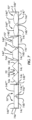
別の態様では、好ましい発明は、冷却塔内のスプラッシュバーハンガーに取り付けるスプラッシュバーに関する。スプラッシュバーは、本体を備え、本体へ、当該本体を通る複数の開口部の間に規定された複数のウェブ(web)を有する閉じた形状の断面を規定する。開口部は、本体内の中空の内部空間を露出させる。本体は、第1の端部と第2の端部とを有し、長手方向軸を規定する。複数のウェブは、第1の端部から第2の端部まで延在する第1のウェブを含む。第1のウェブは、第1の端部と第2の端部との間で、閉じた形状の周りを少なくとも180度(180°)回り込むように、長手方向軸に対して第1の角度又は第1の弧状で延在する。複数の開口部は、第1の端部と第2の端部との間で本体を通って長手方向軸に平行に延在する線が、複数の開口部のうちの少なくとも1つを横切るように、本体に配置される。 In another aspect, the preferred invention relates to splash bars that attach to splash bar hangers in cooling towers. The splash bar includes a body defining a closed-shaped cross section into the body having a plurality of webs defined between a plurality of openings through the body. The opening exposes a hollow interior space within the body. The body has a first end and a second end and defines a longitudinal axis. The plurality of webs includes a first web extending from a first end to a second end. The first web extends between the first end and the second end at a first angle or It extends in a first arc. The plurality of openings are configured such that a line extending parallel to the longitudinal axis through the body between the first end and the second end intersects at least one of the plurality of openings. is placed on the main body.
前述した概要、並びに以下の本発明の詳細な説明は、添付の図面を参照して読めば、よりよく理解されるであろう。本発明を説明する目的で、現在好ましい実施形態が図面に示されている。しかしながら、本発明は、示された具体的な配置及び手法に限定されないことを理解されたい。 The foregoing summary, as well as the following detailed description of the invention, may be better understood when read with reference to the accompanying drawings. For the purpose of illustrating the invention, presently preferred embodiments are shown in the drawings. However, it should be understood that the invention is not limited to the specific arrangements and techniques shown.
特定の用語は、便宜上以下の説明で使用されているにすぎず、限定するものではない。本明細書に具体的に記載しない限り、「1つ(a)」、「1つ(an)」、及び「その(the)」という用語は1つの要素に限定されず、代わりに「少なくとも1つの(at least one)」を意味するものとして解釈されるべきである。「右(right)」、「左(left)」、「下(lower)」、及び「上(upper)」という単語は、参照される図面内の方向を示す。「内側に(inwardly)」又は「遠位に(distally)」、及び「外側に(outwardly)」又は「近位に(proximally)」という用語は、それぞれ、スプラッシュバー及びその関連部分の幾何学的中心又は向きに向かう方向及び離れる方向を指す。用語には、上に列挙した単語、その派生語、及び同意語が含まれる。 Certain terms are used in the following description for convenience only and are not limiting. Unless specifically stated herein, the terms "a", "an", and "the" are not limited to one element, but instead "at least one should be construed to mean "at least one". The words "right," "left," "lower," and "upper" indicate directions in the drawings to which reference is made. The terms "inwardly" or "distally" and "outwardly" or "proximally" refer to the geometric Refers to directions toward and away from the center or direction. The terminology includes the words listed above, derivatives thereof, and synonyms.
本明細書において、「約(about)」、「およそ(approximately)」、「一般に(generally)」、「実質的に(substantially)」という用語、及び同様の用語は、本発明の構成要素の寸法又は特性を説明するときに使用され、記載された寸法/特性が厳密な境界又はパラメータではなく、当業者によって理解されるように、機能的に同一又は類似であって、微小な差異を有するものを除外しないことを示すことも理解されるべきである。少なくとも、数値パラメータを含むような参照は、当技術分野で受け入れられている数学的及び工業的原則(例えば、丸め、測定又は他の系統的誤差、製造公差など)を使用し、最下位桁を変化させないようなバリュエーションを含む。 As used herein, the terms "about," "approximately," "generally," "substantially," and like terms refer to the dimensions of the components of the present invention. or used when describing properties, where the stated dimensions/properties are not strict boundaries or parameters, but are functionally identical or similar with minor differences, as understood by those skilled in the art It should also be understood to indicate that it does not exclude At a minimum, such references involving numerical parameters shall use art-accepted mathematical and industrial principles (e.g., rounding, measurement or other systematic errors, manufacturing tolerances, etc.) and reduce the least significant digits to Includes valuations that remain unchanged.
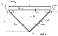
図1~図6を参照すると、一般に符号10で示す第1の好ましいスプラッシュバーは、バー長さL、バー幅W、及びバー高さHを有する押出形状として構成することができる。好ましいバー長さLは、約10インチ(10″)から約18フィート(18´)であり、好ましいバー幅Wは、約3から5インチ(3~5″)であり、好ましいバー高さHは、約1.5から3インチ(1.5~3″)であるが、バー長さL、バー幅W、及びバー高さHは、そのように限定されず、設計者の選好、構成的要求、所望の性能、及び他の要因に基づいて設計及び構成されてもよい。スプラッシュバー10は、冷却塔内のスプラッシュバーハンガー20に取り付けるように構成され、好ましくは、スプラッシュバー10の第1の端部18a及び第2の端部18bの双方が、対向するスプラッシュバーハンガー20によって支持され、追加のスプラッシュバーハンガー20が、第1の端部18aと第2の端部18bとの間でスプラッシュバー10の中央部分を支持するように配置されることもできる。スプラッシュバーハンガー20は、冷却塔に取り付けられた対向するハンガーから構成されることに限定されず、スプラッシュバー10を支持するほぼ任意の構造的支持体から構成されてもよい。例えば、スプラッシュバーハンガー20が下部支持体(図示せず)として構成され、スプラッシュバー10は、その上に積み重ね、冷却媒体が積み重ねられたスプラッシュバー10を通って流れることができ、空気が積み重ねられたスプラッシュバー10を通って流れることができるように構成されてもよい。好ましいスプラッシュバー10は、三角形の断面、好ましくは直角二等辺三角形の断面を有し、第1の脚部14a、第2の脚部14b、及び第3の脚部14cを規定する。しかしながらスプラッシュバー10はこれに限定されず、他のサイズ及び形状を有することができる。第2の好ましい実施形態に関して以下でより詳細に説明されるように、スプラッシュバー10は、例えば、4つの脚部を有する台形形状(図7)を有し、平行な脚部は、一般に、第3の脚部14cと同じ又は同様の方法で配向される。第1の好ましい実施形態では、第1の脚部14aと第2の脚部14bとが接続され、第2の脚部14bと第3の脚部14cとが接続されている。第3の脚部14cは、第1の脚部14aと第2の脚部14bとの交差部に対向して、第1の脚部14aの端部と第2の脚部14bの端部との間に延在している。第1の脚部14aと第2の脚部14bとは、好ましくは、短い脚部14a、14bで構成され、第1の縁部又は第1の隅部16で互いに接続されている。好ましい実施形態では、脚部14a、14b、14cの端部における脚部14a、14b、14cの交差部は、丸みを帯びていることが好ましいが、そのように限定されず、例えば、面取りされるか、又は比較的鋭い縁部を規定するなど、他の方法で配置及び構成されてもよい。
Referring to FIGS. 1-6, a first preferred splash bar, generally designated 10, can be configured as an extruded shape having a bar length L, bar width W, and bar height H. As shown in FIG. The preferred bar length L is about ten inches (10") to about eighteen feet (18'), the preferred bar width W is about three to five inches (3-5"), and the preferred bar height H is about 1.5 to 3 inches (1.5-3″), although bar length L, bar width W, and bar height H are not so limited and are subject to designer preference, configuration. The
第1の脚部14aは、第1の脚平面15aを規定し、第2の脚部14bは、第2の脚平面15bを規定し、第3の脚部14cは、第3の脚平面15cを規定し、第3の脚平面15cは、スプラッシュバーハンガー20に組み立てられた構成で設置されたときに、水平方向に略平行に配向される。好ましいスプラッシュバー10の第1、第2及び第3の脚部14a、14b、14cは、それらの端部で一体的に接続され、スプラッシュバー長さLに沿って閉じた形状を規定する。好ましいスプラッシュバー10の丸みを帯びた隅部及び閉じた形状は、冷却流体が蓄積し得る鋭い縁部又は隅部を制限する。冷却流体の蓄積によって、冷却塔内における下向きに流れる冷却液の流れを形成するポテンシャルを低下させ、これによって、比較的高温の冷却流体が冷却塔の底部の収集槽に直接流れるとき、冷却塔の効率を低下させる可能性がある。第1の好ましいスプラッシュバー10の丸みを帯びた隅部はまた、一般に、冷却媒体、好ましくは水を、脚部14a、14b、14cの表面に更に分配し、続いて様々なサイズの冷却媒体の液滴の形成を促進する。これによって、液滴とアセンブリを通って流れる空気との間の熱伝達を容易にする。一般に、鋭い縁、隅部、又は特徴は、スプラッシュバーにおいて好ましくない。なぜなら、それらは、冷却媒体の流体が蓄積する特徴を形成する可能性があり、それによって、冷却塔内の空気流への曝露が制限された流体流れを形成するか、又は過大な液滴の形成をもたらす可能性がある。更に、好ましくは断面図(図4)で見たときに、好ましくは最長の脚部である第3の脚部14cの配向は、設置された構成において、一般に水平であり、好ましくは第3の脚部の表面上の冷却媒体の液滴の形成を容易にする。第3の脚部の表面上の冷却媒体の液滴は、その後、冷却塔の下部スプラッシュバー10、又は冷却塔の底部の収集槽に落下する。
The
図2~図3Aを参照すると、好ましくは、脚部14a、14b、14c上、より具体的には、脚部14a、14b、14cの外側表面上の溝又はチャネルの形態の表面特徴50はまた、比較的小さな液滴の形成を容易にするか又は液滴の形成を促進する。以下により詳細に説明するように、脚部14a、14b、14cの外側表面への冷却媒体の付着は、冷却塔の効率を改善する。表面特徴50はまた、液滴が脚部14a、14b、14cの外面に衝突したときに、比較的水平に流れる冷却媒体の噴流(jets)の形成を促進するように設計及び構成されることが好ましい。第3の脚部14cからの液滴の形成、並びに第1及び第2の脚部14a、14bからの液滴の形成は、スプラッシュバー10の向きに応じて、冷却塔内のスプラッシュバーアセンブリ(図6)の効率を高めることが好ましい。表面特徴又は溝50は、エンボス加工技術によって脚部14a、14b、14cに形成することが好ましいが、そのように限定されず、スプラッシュバー10の形成中に、外側表面上への材料の堆積によって、又は他の方法でスプラッシュバー10上に形成されてもよい。更に、表面特徴50は、好ましいスプラッシュバー10の外面に形成されることに限定されず、冷却塔で利用される製品のほぼ任意のスプラッシュ面に利用及び形成されて、冷却塔で利用される充填物の任意のスプラッシュ面に望ましい液滴、冷却媒体の噴流、又は他の特徴の形成を容易にすることができる。第1の好ましい実施形態の表面特徴50は、長手方向軸22に対して実質的に垂直に延在するU字形溝50として示されているが、そのように限定されず、水平軸22に対して鋭角に延在することができ、V字形溝50、脚部14a、14b、14cの外面に配置された突起、又は使用中に液滴の形成及び冷却媒体の噴流を促進する他の特徴、例えば、脚部14a、14b、14c上の他の粗面化又はテクスチャ加工された外面などで構成されてもよい。表面特徴50はまた、図3の好ましいスプラッシュバー10の第2の端部18b付近及び図3の断面図にのみ示されているが、表面特徴50は、好ましくは、脚部14a、14b、14cの外面の全てに配置されて組み込まれる。明確にするためにはそのように描かれている。更に、表面特徴50の向き、サイズ、及び形状は、脚部14a、14b、14cのそれぞれにおいて必ずしも一定にするとは限らない、設計者の好みに基づいて、又は性能の目的のために、脚部14a、14b、14c上の異なる位置において異なる向き、形状、及びサイズを有することができる。
Referring to FIGS. 2-3A, preferably surface features 50 in the form of grooves or channels on the
図1~図6を参照すると、好ましいスプラッシュバー10が冷却塔内に配置され、第1の縁部又は隅部16が冷却収集槽に向かって下向きに(図6)、第3の脚部14cが比較的水平に配向されると、冷却媒体は、第1の縁部又は隅部16に向かって流れ、第1の縁部又は隅部16、又はその付近に蓄積することができる。第1の縁部又は隅部16付近、及び一般に第1及び第2の脚部14a、14bの外面上の表面特徴又は溝50は、冷却媒体の液滴の形成を促進する、例えば、表面特徴50によって規定された中間点において比較的小さな液滴の形成を促進することによって、第1の縁部又は隅部16からの冷却媒体の流れを低減する。好ましいスプラッシュバー10が従来技術のハンガーグリッド1に取り付けられ、第3の脚部14cが水平梁3に配置された場合、表面特徴50はまた、好ましくは、第3の脚部14cの外面により小さい液滴を生成するように機能する。更に、脚部14a、14b、14cの外面のいずれかに冷却媒体が衝突すると、表面特徴50は、冷却媒体の噴流を、垂直に対してある角度で外面から比較的小さな流れで外側に移動するように促進することができる。冷却媒体の噴流は、冷却媒体と冷却塔を通って流れる空気との間の熱伝達を促進する。スプラッシュバー10が、第1の隅部16を冷却塔の頂部に向けて配向されると(図7)、冷却媒体は、典型的には、スプラッシュバー10の第1及び第2の脚部14a、14bの外面上に落下して、第1及び第2の脚部14a、14bの外面上で、スプラッシュバー10の側縁17に向かって流れる。側縁17の丸みを帯びた隅部及び表面特徴50は、脚部14a、14b、14cの外面への冷却媒体膜の表面付着、脚部14a、14b、14cの外面における冷却媒体の液滴の形成及び流れ方向についての設計者による制御を容易にする。例えば、表面特徴50のサイズは、表面付着及び液滴の形成を容易にすることができ、振幅が小さい表面特徴50は、外側表面への冷却媒体の蓄積及び微細構造のフラッディング(flooding)を促進することができる。或いは、比較的大きな振幅の表面特徴50は、冷却媒体の滴下、特に所定大きさの液滴の滴下を促進する、外面における滴下ポイント又はエッジを規定することができる。冷却媒体は、好ましくは、アセンブリ内の下部スプラッシュバー10又は収集槽内に落下し、更なる液滴が形成され得る第3の脚部14cにおいて冷却媒体が再分配される。更に、傾斜した上向きの第1及び第2の脚部14a、14bの外面上の表面特徴50は、冷却流体の噴流が生成するように構成され、従って、より小さい冷却媒体又は流体の液滴が冷却塔の効率を改善する。表面特徴50はまた、好ましくは、冷却媒体を下方及び側方に導くように構成される。液滴は、具体的には、液滴が脚部14a、14b、14cの外面上の表面特徴50に当たると、表面特徴50から横方向に導かれ、表面特徴50への液滴の衝撃及び圧力により、液滴が当たったポイントから出発する冷却媒体の横方向の流れ又は移動、及び冷却媒体の横方向の噴流が生じる。
1-6, the
好ましいスプラッシュバー10の閉じた断面は、第1、第2及び第3の脚部14a、14b、14cの間に規定された中央開口部又は中央空隙を提供し、冷却流体の液滴は、好ましくは、冷却塔を通って流れる空気を通って落下し、液滴から空気への熱交換を行う。熱はまた、好ましくは、冷却塔内で落下する液滴と、冷却塔を通って流れる空気との間で交換され、より少ない程度で、脚部14a、14b、14cの表面上の冷却流体の膜との間で交換される。これらのメカニズムは、冷却流体を流れる空気に晒し、冷却流体と空気との間の熱交換を提供する。好ましい脚部14a、14b、14cの閉じた断面形状はまた、好ましくは、輸送のために、スプラッシュバー10を横並べて積み重ねることを容易にする。一方、従来技術のバーは、設置する前に、異なる部品を一緒に組み立てることで構成することができる。これらの組み立てられた従来技術のバーは、剛性が低下し、構造的完全性が制限される。その結果、スプラッシュバーの低い箇所又は領域における冷却流体の垂れ下がり、貯留をもたらし、冷却塔の効率の低下に繋がる。好ましいスプラッシュバー10の中央空隙又は開口部はまた、スプラッシュバー10の代替の実施形態、例えば、4つの脚部及び中央空隙又は開口部を有する台形形状の断面(図7)を有するスプラッシュバー10’ において規定される。この場合、平行な脚部は、好ましくは、設置された構成において水平方向に略平行に配向される。
The closed cross-section of the
好ましいスプラッシュバー10の断面の閉じた形状は、好ましくは、二等辺三角形の形状又は台形形状を有し、これによって、シートタイプのスプラッシュバー又はある形状に組み立てられた従来技術のスプラッシュバーに比べて、比較的強固な強いスプラッシュバー10が構成される。好ましい閉じた形状のスプラッシュバー10は、その強度及び剛性、並びに/又は構成効率が向上したため、冷却塔の支持体の間により長い長さにわたることができる。好ましいスプラッシュバー10は、より広い幅及び閉じた比較的強固な断面形状を有することで、冷却塔での組み立てに必要なスプラッシュバー10の数が少なく、冷却塔に必要な支持体又はハンガーグリッドの数が少ない、設計を容易にすることができる。好ましい閉じた形状のスプラッシュバー10はまた、菱形形状のスプラッシュバーハンガー20及び従来のスプラッシュバーハンガー1と共に使用される場合、冷却塔に設置するのに比較的簡単で効率的である。これは、スプラッシュバー10は、従来技術のスプラッシュバーシステム及びアセンブリの垂直ハンガーグリッドワイヤ2を収容するために縁部スロットの位置合わせを必要とせずに、技術者によって個々の対向するスロット内に押し込むことができるためである。従来技術のスプラッシュバー5は、スプラッシュバー10の好ましい閉じた形状を有しておらず、典型的なスパン及び冷却媒体(水)の負荷の下で、好ましいスプラッシュバー10よりも大きく垂れ下がって曲がり、その結果、冷却媒体は、従来技術のスプラッシュバー5の剛性が低下しているため、従来技術のスプラッシュバー5のミッドスパン付近に貯留する傾向がある。従来技術のスプラッシュバー5はまた、その少ない構造容量、低い構成効率により、ゆがみ(buckle)又折り曲げ(fold)が生じる可能性があるため、支持するための追加のハンガーグリッド1を必要とし、それによってコストが増加し、設置が複雑になる。スプラッシュバー10の好ましい閉じた形状は、強固性及び構造的完全性、並びに/又は構成効率を高め、垂れ下がりを低減し、組み立てられた構成において、スプラッシュバー10のミッドスパン付近の冷却媒体の貯留を低減する。好ましいスプラッシュバー10は、好ましいスプラッシュバー10の強度、剛性、及び構成効率がより高いため、互いにより長い距離を離れて配置されたスプラッシュバーハンガー20に設置されてもよい。距離が長くなると、アセンブリが簡素化され、設置が容易になり、材料費及び労力上のコストが削減される。好ましいスプラッシュバー10はまた、多種多様な材料、例えば、高密度ポリエチレン(HDPE)などを用いた構成を容易にする。一方、従来技術のバーは、通常、ポリ塩化ビニル(PVC)又は金属材料で構成される。
The cross-sectional closed shape of the
好ましいスプラッシュバー10は、従来技術のハンガーグリッド1(図1PA~図3PA)に設置されてもよい。このとき、第3の脚部14cは、水平梁3上に配置され、第1の縁部又は隅部16は、水平梁3から離れて配置される(図7)。冷却媒体の液滴は、好ましくは、従来技術のハンガーグリッド1、又は従来技術のハンガーグリッド1と同様のスタイルを有するハンガーグリッド上に取り付けられたときに、この向きにおいて、脚部14a、14b、14cの間の閉じた空間の反対側の第3の脚部14cの表面から形成されて落下する。液滴の形成及び冷却媒体の水平又は横方向の噴流を促進させるための表面特徴50を有する好ましい直角二等辺三角形の閉じた形状のスプラッシュバー10、及び菱形形状の開口部12は、以下により詳細に説明するように、好ましいスプラッシュバー10のアセンブリを組み込んだ冷却塔の性能を改善する。これらの特徴は、組み合わせて又は個別に設計及び構成することによって、冷却塔の性能及び効率を向上させる。
A
図1~図6を参照すると、第1の好ましい設置構成では、第3の脚部14cは、略水平に配向され、第1の縁部又は隅部16よりも冷却塔の上部付近に配置される。この第1の好ましい設置構成では、第3の脚部14cの外面は、液滴が、設置されたスプラッシュバー10の上方の冷却媒体分配システムから、又はそれぞれの第3の脚部14cの上方のスプラッシュバー10から落下して、スプラッシュバー10に衝突する一次スプラッシュ面である。第1及び第2の脚部14a、14bは、その後、下部スプラッシュバー10又は冷却塔の底部の収集槽内に落下する液滴を発展させるための表面として機能する。一方、スプラッシュバー10が、第3の脚部14cが水平梁3上に配置された従来技術のハンガーグリッド1、又は同様の水平梁3及び垂直懸架部材2のスタイル(図7)を有するハンガーグリッドに設置される場合、第1及び第2の脚部14a、14bは、液滴が設置されたスプラッシュバー10の上方の冷却媒体分配システムから、又はそれぞれの第1及び第2の脚部14a、14bの上方のスプラッシュバー10から落下してスプラッシュバー10に衝突する一次スプラッシュ面として機能する。第3の脚部14cは、好ましいスプラッシュバー10が従来技術のハンガーグリッド1に取り付けられたときに、その後、下部スプラッシュバー10又は冷却塔の底部の収集槽内に落下する液滴を発展させるための表面として機能する。
1-6, in a first preferred installation configuration, the
図1~図6を参照すると、第1の好ましい実施形態では、第1、第2、及び第3の平面15a、15b、15cは、二等辺三角形、好ましくは、直角二等辺三角形を規定する。第1の脚部14aと第2の脚部14bとは、好ましくは、約90度(90°)である第1の角度Δを規定する。更に、第1の脚部14aと第3の脚部14cとは、第1の鋭角Θを規定し、第2の脚部14bと第3の脚部14cとは、第2の鋭角Ωを規定する。第1の好ましい実施形態では、第1の鋭角Θ及び第2の鋭角Ωは、約45度(45°)であるが、そのように限定されず、約30から60度(30~60°)のほぼ任意の鋭角によって構成されてもよい。スプラッシュバー10の好ましい三角形の断面は、二等辺三角形、好ましくは、直角二等辺三角形であり、第1の端部18aと第2の端部18bとの間のバー長さLに沿って比較的一貫した又は一定の断面を有するが、そのように限定されず、バー長さLに沿って可変の断面を有し、スプラッシュバー10の端部18の間に異なる断面を有するように他の方法で設計及び構成されてもよい。第1の角度Δは、90度(90°)に限定されず、約70度から110度(70~110°)とすることができ、スプラッシュバー10の閉じた形状が三角形である場合、第1の角度Δと、第1の鋭角Θと、第2の鋭角Ωとの合計は、好ましくは、180度(180°)であるが、閉じた形状は三角形には限定されない。
1-6, in a first preferred embodiment the first, second and
スプラッシュバー10は、好ましくは、第1の端部18aと第2の端部18bとを含み、第1の端部18aと第2の端部18bとは、端部18とスプラッシュバーハンガー20との係合を容易にするために、スプラッシュバー10の中央部分とは異なる断面を特に有することができる。スプラッシュバー10はまた、好ましくは実質的に中空であり、第1の脚部14aは、第1の厚さt1を有し、第2の脚部14bは、第2の厚さt2を有し、第3の脚部14cは、第3の厚さt3を有する。好ましい第1、第2、及び第3の厚さt1、t2、及びt3は、第1の好ましい実施形態では実質的に同じであるが、そのように限定されず、第1、第2、及び第3の脚部14a、14b、及び14cの長さ及び/又は幅に沿って変化してもよく、又は脚部14a、14b、14cのそれぞれは、性能、構造、審美又は他の目的のために互いに異なる厚さt1、t2、t3を有してもよい。第1、第2、及び第3の厚さt1、t2、及びt3は、好ましい実施形態では約0.050インチ(0.050″)である。
The
スプラッシュバー10は、好ましくは、少なくとも第3の脚部14c内における、又はスプラッシュバー10の外面を通る開口部12を含む。第3の脚部14cの外面は、第1、第2、及び第3の脚部14a、14b、及び14cによって規定された、閉じた又は中空の内部空間15の反対側を向いている。開口部12は、第1の好ましい実施形態では、第1、第2、及び第3の脚部14a、14b、及び14cにおいて比較的均一に分布しているが、そのように限定されず、不均一の間隔で配置されてもよく、様々なサイズ及び形状を有し、第1、第2、及び第3の脚部14a、14b、14cの一部のみ又は選択されたものを通って延在してもよい。開口部12は、様々な方法又はプロセスによって形成されてもよいが、好ましくは、スプラッシュバー10の形成プロセス、例えば、押出プロセスによって規定される。スプラッシュバー10は、その長さLに沿って比較的一貫した中実のプロファイル又は断面を有するように押し出されてもよく、開口部12は、第3の脚部14cに、或いは第1及び第2の脚部14a、14bに形成され、スプラッシュバー10が形成されるときに開口部12を規定する。代替的には、開口部12は、スプラッシュバー10の最初の形成後に、開口部12をスプラッシュバー10に打ち抜くことによって規定されてもよい。第1の好ましいスプラッシュバー10を構成するための好ましい押出プロセスでは、回転ダイヘッド(die head)は、マンドレル(mandrel)と接触する長手方向部材の周りに押し出された部材を巻き付けてもよく、又は逆回転ヘッドを利用してスプラッシュバー10を形成することができる。切れはし及びリサイクル材料は最小限であるが、これらの様々な押出方法で製造されたスプラッシュバー10は、その隅部に追加のアーク又は丸みを有することができる。代替的には、スプラッシュバー10は、脚部14a、14b、14cを切り開いて拡張することによって開口部12を規定するように構成されてもよい。開口部12は、様々なサイズ及び形状有することができ、例えば、菱形(図1~図3及び図5A)、円形、正方形、又は弓形などを有してもよく、そのように限定されず、スプラッシュバー10の通常の動作条件に耐え、開口部12の好ましいサイズをとることができる、スプラッシュバー10の好ましい機能を容易にするほぼ任意のサイズ及び形状を有することができる。開口部12は、スプラッシュバー10の第1、第2、及び第3の脚部14a、14b、及び14cに穿刺、切断、又は形成されてもよく、好ましくは、脚部14a、14b、14cに沿って繰り返しパターンで形成されるが、そのように限定されず、性能目的のために、又はスプラッシュバー10の様々な部分における異なる性能及び冷却媒体の流れ又は反応を促進するために、設計者の好みに基づいて可変で一貫性のないパターン及び形状を有してもよい。好ましい実施形態では、開口部12は、開口部長さx及び開口部幅yを有し、開口部長さxは、好ましい実施形態では約1/2から1インチ(1/2~1″)であり、開口部幅yは、約1/3から1/2インチ(1/3~1/2″)であるが、そのように限定されない。第1の好ましいスプラッシュバー10の開口部12の好ましい構成は、バー長さLが約14インチ(14″)であり、バー幅Wが約3と3/4インチ(3 3/4″)であり、バー高さHが約2インチ(2″)であり、開口部長さxが約4分の3インチ(3/4″)であり、開口部幅yが約3/8インチ(3/8″)である。
好ましいスプラッシュバー10は、第3の脚部14cが水平梁3に隣接して、従来技術のハンガー1に取り付けられたときに、取り付けられた構成において、垂直懸架部材2を受け入れる側縁17にスロット(図示せず)を有するように設計及び構成されてもよい。好ましいスプラッシュバー10は、スロットを含む、又は概ね同様なサイズ及び形状を有するスロットを含むことで垂直懸架部材2を受け入れるには限定されることなく、スプラッシュバー10をスプラッシュバーハンガー20又は従来技術のグリッド1に取り付けることを容易にする異なる形状及び構成、例えば、長方形のスリット、スリップ(slips)、タイ(ties)、接着剤、磁石、又はスプラッシュバー10をハンガー1に固定するためのスロットの好ましい機能を実行することができる他の特徴などを有する代替の特徴から構成されてもよい。第1の縁部16及び側縁17は、それらの長さに沿って比較的中実であってもよく、又はスプラッシュバー10をハンガー1に固定するために利用されるスロットを含んでもよく、或いは、クリップ、リブ、接着剤、長手方向軸22に対して実質的に水平に延在するスリット、又は取り付けられた構成においてスプラッシュバー10とハンガー1、20との間の係合を容易にする他の機構又は方法を含んでもよい。第1の縁部16及び側縁17はまた、開口部12が容易にそれらを通るように構成されてもよい。開口部12は、好ましくは、スプラッシュバー10の処理プロセス又は形成中に、例えば、パルス押出などにより形成されるが、スプラッシュバー10を構成するための好ましいプロセスのうちの1つでは、押し出されたスプラッシュバー10の脚部14a、14b、14cから打ち抜かれた又は切断された材料は、更なる押出プロセスに再利用される。
The
スプラッシュバー10に開口部12を構成する別の好ましい方法は、パルス押出によるものである。このプロセスは、特定の材料、好ましくは、押出ヘッド位置のサイクルに基づいて押し出すことができるポリプロピレン又はポリエチレンなどの熱可塑性ポリマーを利用して、水平部材をスプラッシュバー10内にパルス(pulse)する。このプロセスはまた、約1フィート/秒(1ft/秒)の押出速度、及び約14回/フィート又は14回/秒のサイクルに基づいて特定のパターンを生成する。得られたスプラッシュバー10は、好ましくは、製造中に「引っ張られる」又は伸ばされる狭い長手方向部材を有する。製造において、引き手を用いて、スプラッシュバー10をマンドレル上で水浴に引き込む。材料が完全に固化していない場合、引っ張りプロセスによるウェブ28の伸長及びネッキング(necking)のため、開口部12の間に規定されたスプラッシュバー10のウェブ28の最終形状は、略砂時計形状を有する場合がある。水平部材は、横方向部材を形成するために使用されるパルスプレートの開閉によって、押出方向に細長く、横方向部材は、パルスダイの入口及び出口におけるテーパ状により、楕円形のように成形される。この構成方法を利用して、スプラッシュバー10は、バー幅Wが約3から5インチ(3~5″)、より好ましくは、3.5インチ(3.5″)であり、バー高さHが約1から2.5インチ(1~2.5″)、より好ましくは、1.75インチ(1.75″)であるように構成することができる。パルス押出方法は、好ましくは、個々の脚部14a、14b、14cの間で、比較的一貫した第1、第2、及び第3の厚さt1、t2、及びt3を有するスプラッシュバー10の製造を容易にするが、様々な用途及び冷却塔のために様々な間隔のハンガーグリッド1、20の間に延在する異なるスパンを有するスプラッシュバー10の機能を容易にする、異なる厚さt1、t2、t3を有するスプラッシュバー10を製造することができる。例えば、バー幅Wが3.5インチ(3.5″)である第1の好ましいスプラッシュバー10は、バー幅Wが4インチ(4″)である好ましいスプラッシュバー10よりも、大きい厚さt1、t2、t3を有することができる。そして、バー幅Wが3.5インチ(3.5″)であるスプラッシュバー10は、冷却塔内のより長い距離にまたがるより長い長さLを有し、このスプラッシュバー10は、より長い距離Lにわたって必要な構造荷重を支えることができる。
Another preferred method of constructing the
スプラッシュバー10は、好ましくは、好ましいスプラッシュバー10の一般的なサイズ及び形状をとることができ、スプラッシュバー10の通常の動作条件に耐え、スプラッシュバー10の好ましい機能を実行することができるポリマー材料又は複合材料によって構成される。好ましい実施形態のスプラッシュバー10は、具体的には、機械加工され、形成され、又は成形された金属材料により構成されてもよい。好ましい実施形態のスプラッシュバー10はまた、ポリマー材料、例えば、高密度ポリエチレン(「HDPE」)、低密度ポリエチレン(「LDPE」)、ポリ塩化ビニル(「PVC」)、ポリプロピレン、又は他の関連材料により構成されてもよい。
The
好ましいスプラッシュバー10の開口部12は、略菱形の形状を有する。好ましい菱形は、僅かに矩形状であり、間隔が長い2つの隅部13aがスプラッシュバー10の長手方向軸22に略平行に延在し、間隔が狭い隅部13bが長手方向軸22に略垂直に延在する。図1Aを参照すると、示されている第1の菱形の開口部12aは、開口部軸24を規定する、間隔が長い2つの隅部13aを含む。開口部軸24は、長手方向軸22に略平行に延在する。第1の開口部12aは、第1、第2、及び第3の脚部14a、14b、及び14cのいずれかに配置されてもよく、好ましいスプラッシュバー10の複数の開口部12のいずれかを表すように一般的に示されている。間隔が狭い隅部13bは、好ましい実施形態では開口部軸24及び長手方向軸22に対して略垂直に分離して配置されている又は延在しているが、そのように限定されず、他の方法で設計及び構成されてもよい。開口部12は、菱形に限定されず、スプラッシュバー10に組み込まれ、スプラッシュバー10の通常の動作条件に耐え、本明細書で説明したような開口部12の好ましい機能を果たすことができるほぼ任意のサイズ及び形状を有することができる。開口部12は、例えば、円形、楕円形、正方形、長方形、又は他の形状及びサイズを有することができ、設計者の好み、製造性、又は他の要因に基づいて、スプラッシュバー10において、複数のサイズ及び形状を含むことができる。
The
好ましいスプラッシュバー10の菱形の開口部12は、グリッドパターンに配置され、一貫した間隔で配置されている。それにより、比較的一貫したサイズのウェブ28が隣接する開口部12の間に規定される。ウェブ28は、好ましくは、長手方向軸22に対して鋭角のウェブ角Xで延在し、長手方向軸22に対して鋭角のウェブ角Xで配置される構造的支持を規定するように、鋭角のウェブ角Xで概ね連続的に延在している。開口部12の好ましいグリッドパターンは、個々の菱形の開口部12の各辺に沿って規定された実質的に一貫したサイズの4つのウェブ28を構成する。これらの比較的一貫したサイズのウェブ28は、冷却媒体、好ましくは水を、比較的一貫してウェブ28の表面に付着させる。冷却媒体の一貫した付着及びスプラッシュバー10の表面上の比較的一貫した膜の形成は、特に、冷却媒体が従来技術のスプラッシュバー5上に規定された比較的大きな途切れのない表面上に冷却媒体が溜まる可能性がある従来技術のスプラッシュバー5と比較して、
冷却媒体からの熱伝達を向上させる。これらの一貫したウェブ28はまた、従来技術のスプラッシュバー上の貯留及び流れの形成とは対照的に、ウェブ28上に一貫した液滴の形成を容易にする。従来技術のスプラッシュバーは円形の開口部を含むことができ、そこで
一貫性のないサイズの構造が開口部の間に規定される。その結果、従来技術のスプラッシュバーの表面に、冷却媒体の一貫性のないフィルム化又は貯留が生じる。長手方向軸22に対する鋭角のウェブ角Xでのウェブ28の配向はまた、組み立てられて設置されたスプラッシュバー10を通って流れる強制空気下で、冷却塔の出口端部に向かう流れにおける冷却媒体、好ましくは水の流れを妨げる。従来技術のバー5は、従来技術のスプラッシュバー5の長手方向軸に沿って延在する一般的に真っ直ぐでフラットな表面を有し、バー5の出口端部で、水がスプラッシュバー5の遠位端を越えて流れること、及び水が設置されたバー5から離れるようにドリフトすることが途切れのない表面を提供する。充填物アセンブリからの冷却媒体のこのドリフトは、冷却塔の効率を低下させる。
The diamond-shaped
Improve heat transfer from the cooling medium. These
鋭角のウェブ角Xでのウェブ28の配向は、冷却媒体が、直接流路を流れて、スプラッシュバー10の遠位端に向かって、組み立てられた構成における充填物出口に向かって流れるのをそらす。スプラッシュバー10上の冷却媒体は、通常、スプラッシュバー10の近位端から遠位端に向かって流れる冷却空気の力の下で、スプラッシュバー10の遠位端に向かって付勢される。従来技術のスプラッシュバー5は、冷却媒体をスプラッシュバー表面上の直接の流れから長手方向軸の方向に向ける迂回構成又は特徴を含まない。一方、好ましいスプラッシュバー10は、強制空気の力の下で冷却媒体が長手方向軸22の方向の直接に流れるのを遮断するように、ウェブ28を鋭角のウェブ角Xで配置する。冷却媒体は、開口部12によって、遠位端に向かって直接に流れ流れるのが遮断され、したがって、ウェブ28の配向及び開口部12の菱形は、冷却媒体の遠位端に向かって冷却塔の充填物からのドリフトを低減する。したがって、好ましいスプラッシュバー18は、より多くの冷却媒体の液滴又は冷却媒体の更なるボリュームを下部のスプラッシュバー10に導くことができ、これによって冷却塔の効率を改善する。
The orientation of the
好ましい実施形態では、ウェブ28は、開口部12の間のウェブ幅が約1/8から7/16インチ(1/8~7/16″)であり、その上に表面特徴50を含む。好ましいウェブ幅を有するウェブ28は、水平幅が約3/8インチ(3/8″)とすることができる液滴がウェブ28に直接衝突するときに、冷却媒体の噴流の形成及び液滴の形成を容易にする。ウェブ幅は、好ましくは、液滴がウェブを通過して落下するときにウェブをバイパスすることを防ぐのに十分広く、且つ、動作中のスプラッシュバー10に対する冷却媒体の著しい表面付着を制限するのに十分小さい。
In a preferred embodiment,
図1~図6を参照すると、第1の好ましい実施形態では、スプラッシュバー10は、押出により構成され、好ましくは菱形の開口部12として形成される開口部12を形成する拡張押出への拡張に許容可能なパターンでスリット加工される。好ましいパターンの開口部12を有する好ましいスプラッシュバー10を構成するための押出プロセスは、カットアウト材料のリサイクルがないため、ほぼ100パーセント(100%)の歩留まりを有する。スリット加工プロセスは、好ましくは、サイズベースの段階的な「直径」マンドレル上で行われる。部分冷却は、溶融物の温度を、スプラッシュバー10の押出に比較的高い引張強度を与える温度まで低下させるために実行され、これによって、材料は押出プロセスを通して引っ張ることができる。押出をパターンにスリット加工する機構は、マンドレル上の開始直径の後に配置される。スリット材料は、押し出される材料の熱成形温度又はその付近で、熱成形可能な材料に似た状態で、より大きな直径のマンドレル上に引っ張られる。これは、材料のスリットを機械的に拡張し、開口部12の好ましい拡張された金属菱形形状の構成に近付く。マンドレルは、好ましくは滑らかで連続的であり、半径方向に比較的平坦であるため、拡張されたプラスチック部品は、部材が実質的に平坦であるという点で、平坦化された拡張した金属製品に似ている。これらの部材は、拡張した金属製品の部分的な剪断及び延伸の典型的な製造プロセスに基づいて回転されない。
Referring to FIGS. 1-6, in a first preferred embodiment, the
図1~図3Aを参照すると、スプラッシュバー10の押出成形品は、好ましくは、エンボス加工されて、表面特徴50又は表面上のテクスチャを有する。表面特徴50又は表面上のテクスチャは、押出成形品、最終的には、脚部14a、14b、14c及びウェブ28を横方向に横切って通過する溝(図示せず)から構成されることができる。表面特徴又は溝50は、アンダーカットを生成しないほぼすべての形状を有することができ、例えば、「V」字、「U」字、又は他の形状など、脚部14a、14b、14c及びウェブ28の表面にエンボス加工することができる。脚部14a、14b、14c及びウェブ28の外面に溝又は表面特徴50を追加することは、冷却媒体の液滴がスプラッシュバー10に衝突したときに、表面の水滴又は他の冷却媒体の水圧を増加させるように動作することができる。結果として生じる水又は他の冷却媒体の噴流は、本質的に、水又は他の冷却媒体の表面張力に基づいて、あるディメンションにおいて噴流よりも大きい直径の小さな液滴に分解する。噴流から形成された水又は冷却媒体の液滴は、通常、噴流の直径よりも僅かに大きく、水の表面張力がその表面積を最小にする力を表面に与える。表面特徴50はまた、好ましいスプラッシュバー10の表面上の水流を、好ましい方向、例えば、長手方向軸22に対して略垂直又は長手方向軸22に対してある角度の方向に導くために利用されてもよい。その結果、冷却媒体が長手方向軸22の方向に直接に流れることが妨げられ、冷却媒体は、流れる空気によって付勢され、冷却塔内のスプラッシュバー10の後端又は遠位端に向かって流れることができる。したがって、表面特徴50は、上述したように、ウェブ28の配向及び菱形の開口部12と同様に、冷却媒体のドリフトを制限して、スプラッシュバー10の外面から冷却媒体を排出し、外面への冷却媒体の付着を促進又は阻止し、様々なサイズの冷却媒体の液滴の形成を促進し、又は、冷却媒体が冷却塔の頂部から最終的には収集槽に移動するときに冷却媒体を操作するように構成及び配置することができる。表面特徴50とウェブ28の配向との組合せは、スプラッシュバー10の熱性能を改善する。更に、表面特徴50及びウェブ28の配向は、スプラッシュバー10及びスプラッシュバー10のアセンブリを組み込んだ冷却塔の熱性能を個別に独立して改善する。
1-3A, the extrusion of
図3~図3Dを参照すると、好ましい表面特徴50は、代替の好ましいスプラッシュグリッド200に組み込まれることができる。好ましいスプラッシュグリッド200は、一般に、閉じた中空の内部空間のない平面シート又はパネルの形状で形成されることを除いて、好ましいスプラッシュバー10と同様の特徴を有する。代替の好ましいスプラッシュグリッド200はまた、一般に、好ましいスプラッシュバー10と比較して冷却塔内でより広い幅に跨る。代替の好ましい実施形態のスプラッシュグリッド200は、第1の好ましいスプラッシュバー10と比較した場合、同様の特徴を識別し、説明するときに、好ましいスプラッシュグリッド200を第1の好ましいスプラッシュバー10から区別するために、同様の参照符号に、2(「2」)の接頭辞を付した符号が利用される。記載された相違点を除いて、代替の好ましいスプラッシュグリッド200は、その他において、一般に、第1の好ましいスプラッシュバー10と同様に動作する。
3-3D, the preferred surface features 50 can be incorporated into an alternative
代替の好ましいスプラッシュグリッド200は、第1の端部218a及び第2の端部218bと、好ましい略菱形の開口部212と、長手方向軸222に対して鋭角のウェブ角2Xで延在するウェブ228とを含む。スプラッシュグリッド200はまた、好ましくは、長手方向軸222に略平行に延在する側縁217を含む。代替の好ましいスプラッシュグリッド200は、グリッド長さ2L及びグリッド幅2Wを規定し、グリッド長さ2Lは、好ましくは約1から18フィート(1~18´)の範囲内であり、グリッド幅2Wは、好ましくは約6インチから9フィート(6″~9´)の範囲内であるが、そのように限定されない。第1の端部218a及び第2の端部218bと、側縁217と、ウェブ228とのそれぞれは、好ましくは、上述した表面特徴50と実質的に同じように形成され、動作し、機能する表面特徴50(図3C及び図3D)を含むが、これに限定されない。表面特徴50は、第1の端部218a及び第2の端部218bと、側縁217と、ウェブ228とのそれぞれに含まれることに限定されず、代替の好ましいスプラッシュグリッド200のこれらの要素のうちの特定のものにのみ配置されてもよく、又はスプラッシュグリッド200の第1の端部218a及び第2の端部218bと、側縁217と、ウェブ228との特定の所定の位置に含まれてもよい。表面特徴50は、好ましくは、本明細書で説明するように、第1の好ましいスプラッシュバー10上の表面特徴50の動作及び機能と同様の方法でスプラッシュグリッド200の熱性能を改善する。代替の好ましいスプラッシュグリッド200の表面特徴50が図3C及び図3Dに示されており、側縁217、第1及び第2の端部218a、218b又はウェブ228に形成されたU字形チャネル又はU字形及びV字形チャネルの組合せから構成されることができるが、そのように限定されず、本明細書に記載されるように他の方法で設計及び構成されてもよい。
The alternative
第1の端部218a及び第2の端部218bと、ウェブ228と、側縁217と、を含むスプラッシュグリッド200の略平坦な部分は、好ましいスプラッシュバー10の第1、第2、又は第3の脚部14a、14b、14cのうちの一方として実質的に機能する。スプラッシュグリッド200は、限定されないが、冷却媒体がスプラッシュグリッド200に対して略垂直に落下する状態で、略水平な向きで冷却塔に配置されることが好ましい。スプラッシュグリッド200は、ウェブ228と、側縁217と、第1及び第2の端部218a、218bとの外面を含み、外面における表面特徴50を有する。表面特徴50は、好ましくは、長手方向軸に対して鋭角で延びるものと、長手方向軸に対して略垂直に延びるものとのうちの少なくとも1つである。表面特徴50は、冷却塔の動作中に液滴及び冷却媒体の噴流の形成を促進するように設計及び構成される。表面特徴50は、好ましくはスプラッシュグリッド200の外面における溝により構成され、溝は、好ましくは外面を横切って横方向に、又は代替の好ましい実施形態では長手方向軸222に略垂直に延びる。
A generally planar portion of
図1~図6を参照すると、冷却媒体が水又は実質的に水から構成されている場合、水は、好ましいスプラッシュバー10の脚部14a、14b、14cの表面に自然に付着し、冷却塔の動作中に水の液滴及び噴流が形成される。蓄積された水は、好ましくは、スプラッシュバー10の構造内の低い箇所、不連続部、又は接着が液滴を形成させるより大きな表面上に付着又は付着する液滴を形成する。形成された、スプラッシュバー10から分離されていない液滴は、スプラッシュバー10と接触している流体のある平均温度の水を表す。この大きな液滴は、分離して落下した後、液滴が落下するスプラッシュバー10の下方で、スプラッシュバー10の開口部12のうちの1つを通って落下することによって、運動量の形でエネルギーを持ち、第3の脚部14cの外面又は第1又は第2の脚部14a、14bのうちの一方の表面に衝突する。液滴は、下部スプラッシュバー10に衝突し、結果として生じる噴流を、脚部14a、14b、14cの表面に形成された溝又は表面特徴50の方向に平行に、又は溝又は表面特徴50が形成されていない脚部14a、14b、14cに略垂直に提供する。液滴はまた、スプラッシュバー10の開口部12を通って落下して、下部スプラッシュバー10に衝突するか、又は冷却塔の底部の収集槽に直接落下することができる。より大きな液滴は分離し、それによって、例えば、上部スプラッシュバー10の第1の縁部又は隅部16などから本質的にゼロ速度で底部を離れ、スプラッシュバー10の下方のスプラッシュバー10と衝突する直前にそれらの最大自由落下速度まで加速する。液滴は、下部スプラッシュバー10の開口部12から始まり又は通過し、液滴が最終的に、組み立てられて設置された複数のスプラッシュバー10(図6)の下方の冷却塔の底部の下部スプラッシュバー10、他の液滴、又は収集槽(図示せず)のうちの1つなどの障害物に当たるまで加速し続ける。液滴のエネルギーが限られているか、又は不十分であると、液滴、水、又は冷却媒体がスプラッシュバー10の表面に付着したり、水又は他の冷却媒体のより厚くて短い噴流が発生したりすることがある。より小さな液滴は、スプラッシュバー10の表面に付着し、好ましくは、スプラッシュバー10を覆う水膜に吸収される。スプラッシュバーの底部から生成された液滴の加速は、これらの液滴を、より小さな液滴速度の垂直成分に基づいてより低速で落下する他のより小さな液滴と合体させる。より小さい液滴は、スプラッシュバー10の表面による噴流の効果によって生成されるため、より小さい液滴は、垂直成分及び横方向成分の双方、又は重力及び噴流によってそれぞれ影響を受ける軌道を有する。
1-6, when the cooling medium is or consists essentially of water, the water naturally adheres to the surfaces of the
好ましいスプラッシュバー10を構築するエンボス加工機用のドラムは、スプラッシュバー10の表面上の液滴の衝撃から狭い噴流を生成し、スプラッシュバー10のミッドスパン部分上に水滴を形成することを可能にすることによって液滴のサイズを縮小するように設計されたパターンで、スプラッシュバー10の表面上の谷及び山を規定することができるクロスリブ、V字形溝、U字形溝、正方形溝、又は他の特徴のテクスチャを有することができる。これらの表面特徴、溝又は液滴低減の特徴50は、好ましくは、スプラッシュバー10の表面にエンボス加工され、好ましくは、エンボス加工に使用される方法及びエンボス加工される材料の適切なプロセス条件に応じて、開口部12のスリット加工又は切断前に、又は開口部12のスリット加工又は切断後に、開口部12のスリット加工又は切断と組み合わせて構成される。スプラッシュバー10の形成前、スプラッシュバー10の形成中、及びスプラッシュバー10の構成後に使用されるプロセス及び技術を含む、様々な技術及び方法が使用されて、スプラッシュバー10の表面上に表面特徴、溝、又は液滴低減の特徴50を発展させることができる。更に、表面特徴、溝、又は液滴低減の特徴50は、スプラッシュバー10の外面上で均一であることに限定されず、外面上の所定の位置に適合させることができる。例えば、第1及び第2の端部18a、18b付近に異なる表面特徴50、又はスプラッシュバー10の中央部分に比べて異なる表面特徴50、又は第1、第2および第3の脚14a、14b、14cにおける異なる表面特徴50を有することができる。これらは、スプラッシュバー10が、冷却塔内で下向きに配向された第3の脚部14cによって取り付けられているか、又は設置された構成で略上向きに面しているかに依存することができる。
The drum for the embossing machine that constructs the
スプラッシュバー10の開口部12の好ましい菱形形状は、一般に、冷却塔内の複数のスプラッシュバー10の下部に位置するスプラッシュバー10に液滴が衝突する可能性を高める。従来技術のスプラッシュバー5は、利用可能な表面に影響を与えることなく、より多くの液滴が従来技術の下部スプラッシュバーを通過することを可能にする正方形又は円形の開口部を含む。好ましい菱形の開口部12及びスプラッシュバー10の閉じた形状は、同じ割合のスプラッシュバー10の開口密度に対して、それらのミッドスパンにおける好ましい開口部12のより狭い性質によって衝撃の確率を高める。好ましい菱形の開口部12の同じ断面積に対するより大きい周囲は、落下する水又は他の冷却媒体の液滴によって影響を受けることができるより大きい部材長を提供する。開口部12の好ましい菱形はまた、冷却媒体、好ましくは水が、強制空気出口に向かって脚部14a、14b、14cの表面を直接押し下げられることを最小限に抑える。開口部12の菱形は、スプラッシュバー10の水による液滴の逆流負荷からのドリフトを低減し、空気流に同伴されてドリフトエリミネータ(drift eliminators)に運ばれるか、又は冷却塔から運び出される。
The preferred rhomboidal shape of the
図1~図7、具体的には図7を参照すると、第1の好ましいスプラッシュバー10、第2の好ましいスプラッシュバー10’、第3の好ましいスプラッシュバー10’’及び第4の好ましいスプラッシュバー10’’’は、水平支持体3及び垂直支持体2を有するハンガーグリッドなどの冷却塔のハンガーグリッドに取り付けられることができる。第2、第3、及び第4の好ましい実施形態のスプラッシュバー10’、10’’、10’’’は、第1の好ましいスプラッシュバー10と比較した場合に同様の特徴を有し、同様の参照符号に、第1の好ましい実施形態から第2の好ましい実施形態を区別するために利用されるプライム記号(’)、第3の好ましい実施形態を区別するために利用されるダブルプライム記号(’’)、及び第4の好ましい実施形態を区別するために使用されるトリプルプライム記号(’’’)を付した符号が、同様の特徴を識別及び説明するために利用される。記載された相違点を除いて、スプラッシュバー10’、10’’、10’’’の第2、第3、及び第4の好ましい実施形態は、第1の好ましいスプラッシュバー10と実質的に同じように動作し、好ましくは同じ又は同様の特徴を含む。更に、第1、第2、及び第3の好ましいスプラッシュバー10、10’、10’’は、図6のスプラッシュバーハンガー20に容易に取り付けられることができ、第1、第2、第3、及び第4の好ましいスプラッシュバー10、10’、10’’、10’’’は、従来技術のスプラッシュバーハンガー1、又は関連する冷却塔で動作するための垂直懸架部材2及び水平梁3を有する任意のハンガーに容易に取り付けられることができる。
1-7, and particularly FIG. 7, a first
第2の好ましいスプラッシュバー10’は、第1及び第2又は側部脚部14a’、14b’及び第3又はより長い脚部14c’、並びに第3の脚部14c’から離間され且つ第3の脚部に略平行に配向された第4の脚部14d’を含む台形形状の断面を有する。第2の好ましいスプラッシュバー10’は、脚部14a’、14b’、14c’、14d’及び長手方向軸(図示せず)を通って延在する菱形の開口部(図示せず)、並びに脚部14a’、14b’、14c’、14d’の外面における表面特徴50を含む。第2の好ましいスプラッシュバー10’は、冷却塔のハンガー又はハンガーグリッドに取り付け可能であり、好ましくは、第3の脚部14c’は、冷却塔の充填材を通る冷却媒体の流れに対して水平又は垂直に配向される。第2の好ましいスプラッシュバー10’の第4の脚部14d’はまた、冷却塔に取り付けられたときに冷却媒体の流れに対して略水平又は垂直に配向される。第3の好ましいスプラッシュバー10’’は、第3の脚部14c’’及び第4の脚部14d’’を含む長側と、第1の脚部14a’’及び第2の脚部14b’’を含む短側と、を備える楕円形の断面を有する。第4の好ましいスプラッシュバー10’’’は、第1、第2、第3及び第4の脚部14a’’’、14b’’’、14c’’’、及び14d’’’を有する正方形の断面を有し、第3及び第4の脚部14c’’’、14d’’’は、好ましくは設置された構成において冷却媒体の流れ方向に対して略水平又は垂直に配向される。第3及び第4の好ましいスプラッシュバー10’’、10’’’はまた、好ましくは、本明細書に記載の菱形の開口部及び表面特徴50を含む。
A second preferred splash bar 10' is spaced from first and second or
動作中、第1、第2、第3、及び第4の好ましいスプラッシュバー10、10’、10’’、10’’’は、好ましくは、第3及び第4の脚部14c、14c’、14c’’、14c’’’、14d’、14d’’、14d’’’が冷却媒体の流れ方向に対して略垂直に配向された状態で、ハンガーグリッド5、20によって支持された冷却塔に配置される。スプラッシュバー10、10’、10’’、10’’’は、冷却媒体の液滴及び噴流、並びにスプラッシュバー10、10’、10’’、10’’’の外面上の膜の形成によって、冷却塔の動作中に冷却媒体と充填材を通って流れる空気との間の熱交換を強化する。
In operation, the first, second, third and fourth preferred splash bars 10, 10', 10'', 10''' are preferably configured with third and
図8及び図9を参照すると、第5の好ましいスプラッシュバー110は、好ましいハンガーグリッド20、又は水平支持体3及び垂直支持体2を有するハンガーグリッドなどの冷却塔のハンガーグリッドに取り付けられることができる。第5の好ましいスプラッシュバー110は、第1、第2、第3及び第4の好ましいスプラッシュバー10、10’、10’’、10’’’と比較した場合に同様の特徴を有し、第5の好ましい実施形態を他の好ましいスプラッシュバー10、10’、10’’、10’’’と区別するために、同様の参照符号に番号1(「1」)の接頭辞を付した符号が、同様の特徴を識別及び説明するために利用される。記載された相違点を除いて、スプラッシュバー110の第5の好ましい実施形態は、第1、第2、第3、及び第4の好ましいスプラッシュバー10、10’、10’’、10’’’と実質的に同じように動作し、好ましくは同じ又は同様の特徴を含む。
8 and 9, a fifth preferred splash bar 110 can be attached to a hanger grid of a cooling tower, such as the
第5の好ましいスプラッシュバー110は、第1の好ましいスプラッシュバー10と比較して比較的開いた設計を有し、より大きな開口部112及び開口部112の間のより狭いウェブ128を有する。更に、ウェブ128は、長手方向軸122に実質的に平行に延在する長手方向ウェブ128aと、長手方向軸122及び長手方向ウェブ128aに対して鋭角のウェブ角Oで延在する傾斜ウェブ128bとを含む。第5の好ましいスプラッシュバー110は、第1の脚部114aと第2の脚部114bとの間の第1の角度1Δと、第1の脚部114aと第3の脚部114cとの間の第1の鋭角1Θと、第2の脚部114bと第3の脚部114cとの間第2の鋭角1Ωと、をそれぞれ有する直角二等辺三角形の断面を有する。好ましい直角二等辺三角形断面を有する第5の好ましいスプラッシュバー110は、スプラッシュバー110を、菱形窓を有する好ましいハンガー20及び従来技術のハンガーに、好ましくは、設置された構成において、略水平に向けられた第3の脚部114cによって取り付けることを容易にする。
The fifth preferred splash bar 110 has a relatively open design compared to the first
図1、図3、図5A及び図10~図12を参照すると、第6、第7及び第8の好ましいスプラッシュバー610、710、810は、好ましいハンガーグリッド20、又は水平支持体3及び垂直支持体2を有するハンガーグリッドなどの冷却塔のハンガーグリッドに取り付けられることができる。第6、第7、及び第8の好ましいスプラッシュバー610、710、810は、第1、第2、第3、第4、及び第5の好ましいスプラッシュバー10、10’、10’’、10’’’、110と比較した場合に同様の特徴を有し、第6、第7、及び第8の好ましい実施形態を他の好ましいスプラッシュバー10、10’、10’’、10’’’、110からそれぞれ区別するために、同様の参照符号に番号6、7、及び8(「6」、「7」、「8」)の接頭辞を付した符号が、同様の特徴を識別及び説明するために利用される。記載された相違点を除いて、スプラッシュバー610、710、810の第6、第7、及び第8の好ましい実施形態は、第1、第2、第3、第4、及び第5の好ましいスプラッシュバー10、10’、10’’、10’’’、110と実質的に同じように動作し、好ましくは同じ又は同様の特徴を含む。
1, 3, 5A and 10-12, the sixth, seventh and eighth preferred splash bars 610, 710, 810 are preferably
第6、第7、及び第8の好ましいスプラッシュバー610、710、810は、明確にするために、スプラッシュバー610、710、810の本体の閉じた形状の周りに延在する複数のウェブのうちの単一のウェブ又は第1のウェブ628、728、828のみを有するスプラッシュバー610、710、810のワイヤフレームとして図10~図12に示されているが、好ましいスプラッシュバー610、710、810は、開口部12の間に規定される複数のウェブ28を有する第1の好ましいスプラッシュバー10に示されているように、複数のウェブ28を含む。第6の好ましいスプラッシュバー610は、略円形の断面を有し、第7の好ましいスプラッシュバー710は、略三角形の断面を有し、第8の好ましいスプラッシュバー810は、本体に台形の断面を有して、略閉じた断面形状を規定している。第6、第7、及び第8の好ましいスプラッシュバー610、710、810は、これらの断面形状に限定されず、本明細書で説明するように、好ましいスプラッシュバー610、710、810の一般的なサイズをとることができ、好ましいスプラッシュバー610、710、810の通常の動作条件に耐え、スプラッシュバー610、710、810の好ましい機能を実行することができれば、閉じた断面形状を規定するほぼ任意の形状を有することができる。スプラッシュバー610、710、810は、冷却塔の好ましいハンガーグリッド20、又は水平支持体3及び垂直支持体2を有するハンガーグリッドに取り付けるように設計及び構成されている。
The sixth, seventh, and eighth preferred splash bars 610, 710, 810 are, for clarity, of a plurality of webs extending around the closed shape of the body of the
第6、第7、及び第8の好ましいスプラッシュバー610、710、810は、本体を通る開口部(図示せず)の間に規定された複数のウェブ(図示せず)を含むが、図10~図12は、明確にするために第1の端部618a、718a、818aから第2の端部618b、718b、818bまで延在する第1のウェブ628、728、828のみ、及びスプラッシュバー610、710、810の閉じた断面形状の周りに一方向に延在する第1のウェブ628、728、828のみを示しているが、好ましいスプラッシュバー610、710、810は、好ましくは、第1の好ましいスプラッシュバー10に示されているように、第1の端部18a、618a、718a、818aと、第2の端部18b、618b、718b、818bとの間で互いに交差するウェブを有し、交差するウェブ28は、隣接する開口部12の間に規定される。開口部は、冷却媒体の液滴及び噴流が開口部を通って落下することができ、液滴及び噴流が冷却塔を流れる空気と熱交換するように、本体の閉じた断面形状内の中空の内部空間615、715、815を露出させる。第1、第6、第7及び第8の好ましいスプラッシュバー10、610、710、810の本体は、第1の端部18a、618a、718a、818a及び第2の端部18b、618b、718b、818bを有し、長手方向軸22、622、722、822を規定する。複数のウェブ28は、第1の端部18a、618a、718a、818aから第2の端部18b、618b、718b、818bまで延在する第1のウェブ28a、628、728、828を含む。第1のウェブ28a、628、728、828は、第1の端部18a、618a、718a、818aと、第2の端部18b、618b、718b、818bとの間で、第1のウェブ28a、628、728、828が、本体の閉じた形状の周りを、少なくとも180度(180°)回り込むように、長手方向軸22、622、722、822に対して鋭角のウェブ角、又は第1の角度X、又は第1の弧状で延在する。第1のウェブ28a、628、728、828はまた、一般に、バー長さL、6L、7L、8L及び長手方向軸22、622、722、822に対する複数のウェブ28、28a、628、728、828の向きに応じて、第1の端部18a、618a、718a、818aと、第2の端部18b、618b、718b、818bとの間の本体の閉じた形状の周りを、例えば、360度(360°)など、更に回り込むことができる。バー長さL、6L、7L、8Lは、好ましくは少なくとも10インチ(10″)であり、好ましくは10インチから18フィート(10″~18´)のバー長さL、6L、7L、8Lを有することができる。開口部22は、第1の端部18a、618a、718a、818aと、第2の端部18b、618b、718b、818bとの間で、本体を通って長手方向軸22、622、722、822に平行に延在する線が開口部の少なくとも1つを横切るか、又はそれを通って延在するように、スプラッシュバー10、610、710、810の本体に配置される。従って、この好ましい構成では、流れる冷却媒体の長手方向軸22、622、722、822に沿った又は平行な直接的な直線経路は、第1の端部18a、618a、718a、818aと、第2の端部18b、618b、718b、818bとの間に規定されない。第1端部18a、618a、718a、818aと、第2の端部18b、618b、718b、818bとの間の任意の直線経路は、開口部22の少なくとも1つによって中断され、その結果、冷却塔を通って又は好ましいスプラッシュバー10、610、710、810に沿って流れる空気によって押される冷却媒体は、第1の端部18a、618a、718a、818aと、第2の端部18b、618b、718b、818bとの間に直接的な表面流路を有さない。直接的な表面流路は、スプラッシュバー10、610、710、810のアセンブリから、そして冷却塔から吹き出される冷却媒体をもたらし、それによって、望ましくない冷却塔の効率の低下が生じる。
The sixth, seventh, and eighth preferred splash bars 610, 710, 810 include a plurality of webs (not shown) defined between openings (not shown) through the body, but shown in FIG. - FIG. 12 show only
第7及び第8の好ましいスプラッシュバー710、810において、第1のウェブ728、828は、長手方向軸722、822に対して第1の鋭角のウェブ角7X、8Xで延在し、第6の好ましいスプラッシュバー610において、第1のウェブ628は、長手方向軸622に対して弧状で、又はスプラッシュバー610の閉じた略円筒形状の周りの弧状の経路で延在する。第6、第7、及び第8の好ましいスプラッシュバー610、710、810はまた、第1のウェブ628、728、828と略平行に交差又は延在する追加の複数のウェブ(図示せず)を含むが、明確にするために追加のウェブは示されていない。追加のウェブは、スプラッシュバー610、710、810及び冷却媒体のスプラッシュ面に更なる構造的完全性を提供する。ウェブ628、728、828はまた、上述したように、好ましい表面特徴又は溝50を含むことができる。
In the seventh and eighth preferred splash bars 710, 810, the
図10を参照すると、第6の好ましいスプラッシュバー610は、第1のウェブ628の弧状と、本体を規定するために長手方向軸622の周りに弧状に延在する更なる複数のウェブ(図示せず)とを規定する押出プロセスにより構成することができる。第1のウェブ628及び更なる複数のウェブは、長手方向軸622の周りの一方向に延在することに限定されず、第1の端部618aと第2の端部618bとの間で方向、向き、及び弧状の曲率を変化させてもよい。例えば、押出プロセスは、第1及び更なる複数のウェブ628を第1の弧状及び向きの弧状にし、続いて、スプラッシュバー610の所定の長さが形成された後に反対の向き及び弧状に切り替えることができる。或いは、ウェブ628が、長手方向軸622に対して相対的に直線的な向きに形成され、続いて、長手方向軸622に対してある角度又は弧状に変形してスプラッシュバー622を規定することができる。
Referring to FIG. 10, a sixth
当業者であれば、その広範な発明概念から逸脱することなく、上述した好ましい実施形態に変更を加えることができることを理解するであろう。したがって、本発明は、開示された特定の実施形態に限定されず、本開示によって定義される本発明の精神及び範囲内の変更を包含することが意図されていることが理解される。 Those skilled in the art will appreciate that changes can be made to the preferred embodiments described above without departing from the broad inventive concept thereof. It is therefore to be understood that this invention is not limited to the particular embodiments disclosed, but is intended to encompass modifications within the spirit and scope of the invention as defined by this disclosure.
Claims (12)
本体を備え、
前記本体は、前記本体を通る複数の開口部の間に規定された複数のウェブを有し、閉じた形状の断面を規定し、前記閉じた形状の断面の形状は第1の脚部と、第2の脚部と、第3の脚部とを有する三角形又は台形形状であって、前記開口部は、前記本体内の中空の内部空間を露出させ、
前記本体は、第1の端部と第2の端部とを有し、長手方向軸を規定し、複数の前記ウェブは、前記第1の端部から前記第2の端部まで延在する第1のウェブと、前記第1の端部から前記第2の端部まで延在する第2のウェブとを含み、
前記第1のウェブは、前記長手方向軸に対して第1の角度で延在し、前記第2のウェブは、前記長手方向軸に対して第2の角度で延在し、前記第1のウェブと前記第2のウェブとは、前記第1の端部と前記第2の端部との間で、前記閉じた形状の周りを少なくとも360度回り込み、
複数の前記開口部は、前記第1の端部と前記第2の端部との間に、前記本体を通って前記長手方向軸に平行に延在する線が複数の前記開口部のうちの少なくとも1つを横切るように、前記本体に配置され、
前記第1のウェブは、第1延在面に沿って前記閉じた形状の周りを回りこみ、前記第2のウェブは、前記第1延在面よりも外側の第2延在面に沿って前記閉じた形状の周りを回りこむように構成されている、
スプラッシュバー。 A splash bar for attachment to a splash bar hanger in a cooling tower, comprising:
Equipped with a main body,
the body having a plurality of webs defined between a plurality of openings through the body and defining a closed-shaped cross-section, the closed-shaped cross-sectional shape defining a first leg; a triangular or trapezoidal shape having a second leg and a third leg, the opening exposing a hollow interior space within the body;
The body has a first end and a second end and defines a longitudinal axis, the plurality of webs extending from the first end to the second end. a first web and a second web extending from said first end to said second end;
The first web extends at a first angle with respect to the longitudinal axis, the second web extends at a second angle with respect to the longitudinal axis, and the first web extends at a second angle with respect to the longitudinal axis. the web and said second web wrap at least 360 degrees around said closed shape between said first end and said second end;
the plurality of openings having a line extending parallel to the longitudinal axis through the body between the first end and the second end of the plurality of openings; disposed on the body across at least one;
The first web wraps around the closed shape along a first extension surface, and the second web extends along a second extension surface outside the first extension surface. configured to wrap around the closed shape;
splash bar.
請求項1に記載のスプラッシュバー。 wherein the first web and the second web rotate around the closed shape in opposite directions and are configured by counter-rotating die heads;
A splash bar according to claim 1.
請求項10に記載のスプラッシュバー。 The first web wraps around the closed shape in a first direction and the second web wraps around the closed shape in a second direction opposite the first direction. Coming,
Splash bar according to claim 10 .
請求項10に記載のスプラッシュバー。 the plurality of said webs minimizes scraps and recycled material during the construction process;
Splash bar according to claim 10 .
Applications Claiming Priority (3)
| Application Number | Priority Date | Filing Date | Title |
|---|---|---|---|
| US201962869724P | 2019-07-02 | 2019-07-02 | |
| US62/869,724 | 2019-07-02 | ||
| PCT/US2019/041798 WO2021002877A1 (en) | 2019-07-02 | 2019-07-15 | Cooling tower splash bar and related assembly |
Publications (2)
| Publication Number | Publication Date |
|---|---|
| JP2022531623A JP2022531623A (en) | 2022-07-07 |
| JP7331237B2 true JP7331237B2 (en) | 2023-08-22 |
Family
ID=74100950
Family Applications (1)
| Application Number | Title | Priority Date | Filing Date |
|---|---|---|---|
| JP2022500112A Active JP7331237B2 (en) | 2019-07-02 | 2019-07-15 | Cooling tower splash bars and related equipment |
Country Status (8)
| Country | Link |
|---|---|
| US (1) | US11543192B2 (en) |
| EP (1) | EP3994411A4 (en) |
| JP (1) | JP7331237B2 (en) |
| CN (1) | CN114174759B (en) |
| AU (1) | AU2019452691B2 (en) |
| CA (1) | CA3143671C (en) |
| MX (1) | MX2021016121A (en) |
| WO (1) | WO2021002877A1 (en) |
Citations (3)
| Publication number | Priority date | Publication date | Assignee | Title |
|---|---|---|---|---|
| US20090174090A1 (en) | 2008-01-09 | 2009-07-09 | Evapco, Inc. | Splash bar |
| JP2016221966A (en) | 2015-05-27 | 2016-12-28 | 東京インキ株式会社 | Mesh-like resin molding, structure, and method for using mesh-like resin molding |
| US20190024993A1 (en) | 2017-07-21 | 2019-01-24 | Karl Anthony Tobin | Cooling tower fill structures |
Family Cites Families (77)
| Publication number | Priority date | Publication date | Assignee | Title |
|---|---|---|---|---|
| US2634959A (en) | 1949-05-09 | 1953-04-14 | Cave John Richard | Gas-liquid contact apparatus |
| DE1100597B (en) | 1952-11-29 | 1961-03-02 | Atomic Energy Authority Uk | Packing for steam-liquid and gas-liquid countercurrent contact columns |
| US2780306A (en) | 1953-08-31 | 1957-02-05 | John R Boyle | Cooling tower |
| US3410057A (en) | 1964-01-09 | 1968-11-12 | Bernard J. Lerner | Method for gas-liquid disentrainment operations |
| US3346246A (en) | 1965-01-25 | 1967-10-10 | Marley Co | Cooling tower fill assembly of foraminous sheet material |
| US3389895A (en) * | 1967-01-24 | 1968-06-25 | Flon Anderson Co Inc De | Cooling tower fill bar |
| US3468521A (en) | 1967-10-27 | 1969-09-23 | Fluor Prod Co Inc | Splash directing fill for cooling towers |
| US3894127A (en) | 1969-09-11 | 1975-07-08 | Marley Co | Fill assembly structure for cross flow water cooling tower |
| US3791634A (en) | 1970-04-29 | 1974-02-12 | P Phelps | Cross flow tower fill of cellular construction |
| US3647191A (en) * | 1970-07-27 | 1972-03-07 | Marley Co | Splash bar for cooling tower fill assembly |
| US3749381A (en) | 1970-08-12 | 1973-07-31 | Ecodyne Cooling Prod | Fill hanger |
| JPS486650U (en) * | 1971-06-07 | 1973-01-25 | ||
| GB1363416A (en) | 1971-09-03 | 1974-08-14 | Ames Crosta Mills & Co Ltd | Biological filtration apparatus |
| JPS49130136U (en) * | 1973-03-10 | 1974-11-08 | ||
| US3969447A (en) | 1973-10-18 | 1976-07-13 | Fritz W. Glitsch & Sons, Inc. | Grids for fluid contact apparatus |
| GB1470196A (en) | 1974-11-13 | 1977-04-14 | Cooling Dev Ltd | Contact packing |
| US4020130A (en) | 1975-08-21 | 1977-04-26 | Ovard John C | Splash bar for cooling tower fill assembly |
| JPS5245584A (en) * | 1975-10-09 | 1977-04-11 | Seiko Kakoki Kk | Vapor-liquid contacting unit |
| US4052491A (en) | 1976-06-25 | 1977-10-04 | Research-Cottrell, Inc. | Modular gas and liquid contact means |
| US4133851A (en) | 1977-05-11 | 1979-01-09 | Ecodyne Corporation | Cooling tower splash bar fill assembly and method |
| US4115484A (en) | 1977-09-16 | 1978-09-19 | Ecodyne Corporation | Cooling tower fill assembly |
| ZA781679B (en) | 1978-03-22 | 1979-07-25 | Wlpu Holdings Ltd | Improvements in or relating to cooling towers |
| US4178333A (en) | 1978-06-15 | 1979-12-11 | Shepherd Charles E | Hanger assembly for fill strips |
| US4276242A (en) | 1979-11-19 | 1981-06-30 | Koch Engineering Company, Inc. | Vapor-liquid contact grid apparatus |
| US4481154A (en) | 1981-03-20 | 1984-11-06 | Cal Gavin Limited | Insert for placement in a vessel and method of forming the insert |
| US4879084A (en) | 1982-03-12 | 1989-11-07 | Rudolf Parnigoni | Method of forming a net-like structure |
| US4515735A (en) | 1982-09-29 | 1985-05-07 | Phelps Peter M | Slotted splash bars for gas liquid contact apparatus |
| US4439378A (en) | 1983-05-23 | 1984-03-27 | Ovard John C | Cooling tower splash bar method and apparatus |
| US4604247A (en) | 1983-06-21 | 1986-08-05 | Glitsch, Inc. | Tower packing material and method |
| DE8330573U1 (en) | 1983-10-25 | 1984-02-02 | Vereinigte Füllkörper-Fabriken GmbH & Co, 5412 Ransbach-Baumbach | FILLER BODY FOR MATERIAL REPLACEMENT COLONES |
| US4578227A (en) | 1984-03-15 | 1986-03-25 | Ovard John C | Splash bar method and apparatus |
| US4562015A (en) | 1984-05-22 | 1985-12-31 | The Munters Corporation | Open mesh fill assembly |
| US4557878A (en) | 1984-05-22 | 1985-12-10 | Munters Corporation | Splash-type fill |
| US4576764A (en) | 1984-12-31 | 1986-03-18 | C. E. Shepherd Company | Fill slat assembly for cooling towers |
| US4676934A (en) | 1985-09-27 | 1987-06-30 | Jaeger Products, Inc. | Structured WV packing elements |
| US4705653A (en) | 1985-10-28 | 1987-11-10 | Research-Cottrell, Inc. | Splash bar for cooling tower fill assembly |
| US4762650A (en) | 1986-02-25 | 1988-08-09 | Wlpu Holdings Proprietary Limited | Packing elements for evaporative coolers and a method of supporting packing elements in cooling towers |
| CN1016463B (en) * | 1987-04-10 | 1992-04-29 | 卡马戈有限公司 | Packing element for evaporative coolers and method of supporting packing element in cooling waters |
| US4803018A (en) | 1987-07-16 | 1989-02-07 | Marcel R. Lefevre | Splash fill for heat and mass transfer apparatus and method of making a splash fill assembly |
| DE3723804A1 (en) | 1987-07-18 | 1989-01-26 | Norddeutsche Seekabelwerke Ag | FILLED BODY |
| US4915877A (en) * | 1989-05-18 | 1990-04-10 | Shepherd Charles E | Fill assembly for cooling tower |
| DE4111451A1 (en) * | 1991-04-09 | 1992-10-15 | Balcke Duerr Ag | GIANT INSTALLATION ELEMENT FOR COOLING TOWERS |
| US5104588A (en) | 1991-04-25 | 1992-04-14 | The Marley Cooling Tower Company | Perforated trapezoidal-shaped fill bar for splash type water cooling towers |
| US5112537A (en) | 1991-04-25 | 1992-05-12 | The Marley Cooling Tower Company | Perforated arch-shaped fill bar for splash type water cooling tower |
| JPH0511720U (en) * | 1991-07-29 | 1993-02-12 | 矢崎総業株式会社 | Net tube for wire harness |
| US5185105A (en) | 1992-04-01 | 1993-02-09 | Peterson Charles A | Splash bar construction for a cooling tower |
| US5374381A (en) | 1992-11-10 | 1994-12-20 | Rps Products, Inc. | Evaporative element for a humidifier and method of making the same |
| EP0599782B1 (en) | 1992-11-24 | 1997-12-29 | Kühni Ag | Method and machine for making expanded metal |
| US5279774A (en) | 1992-12-14 | 1994-01-18 | Remy Helmut L | Contact filling for cooling towers |
| US5460755A (en) * | 1993-06-23 | 1995-10-24 | T. C. Watermeyer Group, Inc. | Packing elements, a pack, a method of constructing a pack, and a method for installing a packing in an evaporative cooler |
| US5372752A (en) | 1993-06-23 | 1994-12-13 | T. C. Watermeyer Group, Inc. | Packing elements, a pack, a method of constructing a pack, and a method for installing a packing in an evaporative cooler |
| US5454987A (en) | 1994-10-11 | 1995-10-03 | Cooling Tower Technologies, Inc. | Splash bar for cooling tower |
| EP0899532B1 (en) | 1997-08-27 | 2002-11-06 | Balcke-Dürr GmbH | Packing element for cooling towers |
| US6083441A (en) | 1998-09-14 | 2000-07-04 | Nsw Corporation | Method for making a stackable and inexpensively transportable splash bar structure |
| US6293527B1 (en) | 1999-04-16 | 2001-09-25 | John C. Ovard | Splash bar for direct contact heat and mass transfer method and apparatus |
| DE10031119A1 (en) | 2000-06-30 | 2002-01-10 | Basf Ag | Packings for heat and mass transfer columns |
| US6708960B2 (en) | 2001-07-10 | 2004-03-23 | Integrid Inc. | Cooling tower support grid |
| RU2243467C2 (en) | 2003-03-03 | 2004-12-27 | Открытое акционерное общество "Всероссийский научно-исследовательский институт гидротехники им. Б.Е. Веденеева" | Sprinkle for a heat-mass exchange apparatus |
| US20050051916A1 (en) * | 2003-09-08 | 2005-03-10 | C.E. Shepherd Co., Inc. | Cooling media pack |
| AU2006200056B2 (en) | 2005-01-21 | 2011-01-20 | Thermfresh International Pty Ltd | Air handling heat exchanger humidifying apparatus |
| AU2012200664A1 (en) | 2005-03-23 | 2012-03-01 | Expo-Net Danmark A/S | A contact filter block, a method of producing structural elements of a contact filter block and an apparatus for producing structural elements of a contact filter block |
| ATE403493T1 (en) | 2005-06-08 | 2008-08-15 | Ver Fuellkoerper Fab | METHOD FOR PRODUCING A FILLING BODY FOR MATERIAL AND HEAT EXCHANGE AND FILLING BODY PRODUCED BY THE METHOD |
| US7618026B2 (en) | 2005-09-01 | 2009-11-17 | Armstrong Charles M | Cooling tower fill support grid assembly and method |
| GB0605599D0 (en) | 2006-03-21 | 2006-04-26 | Transvac Systems Ltd | Matrix arrangement |
| US7559541B2 (en) | 2006-09-27 | 2009-07-14 | Spx Cooling Technologies, Inc. | Splash bar apparatus and method |
| FR2937896B1 (en) | 2008-10-30 | 2013-03-01 | Corelco Sas | METHOD AND DEVICE FOR SIMULTANEOUS EXTRUSION OF TWO TUBES OF SYNTHETIC MATERIAL |
| US8926305B2 (en) | 2009-11-12 | 2015-01-06 | Kucharco Corporation | General purpose dispenser to deploy and expand web material |
| US8960259B2 (en) | 2010-09-14 | 2015-02-24 | University Of South Florida | Variable screening |
| US9291395B2 (en) | 2013-07-10 | 2016-03-22 | Spx Cooling Technologies, Inc. | Splash bar assembly and method of installation |
| US20150130094A1 (en) | 2013-11-12 | 2015-05-14 | Spx Cooling Technologies, Inc. | Splash bar module and method of installation |
| US9546830B2 (en) | 2014-01-28 | 2017-01-17 | Brentwood Industries, Inc. | Composite hanger grid and components, splash bar, assembly thereof and method of assembly |
| CN204373449U (en) | 2014-12-08 | 2015-06-03 | 上虞市航宇冷却塔有限公司 | Anti-blocking cooling tower |
| WO2017053820A1 (en) * | 2015-09-23 | 2017-03-30 | Composite Cooling Solutions, L.P. | Hybrid wet/dry cooling tower and improved fill material for cooling tower |
| US10302378B2 (en) | 2017-01-31 | 2019-05-28 | Midwest Cooling Towers, Inc. | Support beam for cooling tower fill assembly |
| USD843600S1 (en) | 2017-01-31 | 2019-03-19 | Midwest Cooling Towers, Inc. | Support beam for cooling tower fill assembly |
| CN207379316U (en) | 2017-07-18 | 2018-05-18 | 浙江永春科技股份有限公司 | A kind of blended cotton cooling tower of high power block-proof type |
| WO2021002878A1 (en) * | 2019-07-02 | 2021-01-07 | Brentwood Industries, Inc. | Cooling tower splash bar hanger and related assembly |
-
2019
- 2019-07-15 US US17/622,326 patent/US11543192B2/en active Active
- 2019-07-15 JP JP2022500112A patent/JP7331237B2/en active Active
- 2019-07-15 MX MX2021016121A patent/MX2021016121A/en unknown
- 2019-07-15 EP EP19936316.9A patent/EP3994411A4/en active Pending
- 2019-07-15 AU AU2019452691A patent/AU2019452691B2/en active Active
- 2019-07-15 CN CN201980098193.XA patent/CN114174759B/en active Active
- 2019-07-15 CA CA3143671A patent/CA3143671C/en active Active
- 2019-07-15 WO PCT/US2019/041798 patent/WO2021002877A1/en not_active Ceased
Patent Citations (3)
| Publication number | Priority date | Publication date | Assignee | Title |
|---|---|---|---|---|
| US20090174090A1 (en) | 2008-01-09 | 2009-07-09 | Evapco, Inc. | Splash bar |
| JP2016221966A (en) | 2015-05-27 | 2016-12-28 | 東京インキ株式会社 | Mesh-like resin molding, structure, and method for using mesh-like resin molding |
| US20190024993A1 (en) | 2017-07-21 | 2019-01-24 | Karl Anthony Tobin | Cooling tower fill structures |
Also Published As
| Publication number | Publication date |
|---|---|
| CA3143671C (en) | 2023-02-21 |
| CN114174759B (en) | 2022-10-21 |
| EP3994411A1 (en) | 2022-05-11 |
| EP3994411A4 (en) | 2023-11-08 |
| CA3143671A1 (en) | 2021-01-07 |
| US20220205744A1 (en) | 2022-06-30 |
| AU2019452691A1 (en) | 2022-01-27 |
| AU2019452691B2 (en) | 2022-05-26 |
| US11543192B2 (en) | 2023-01-03 |
| JP2022531623A (en) | 2022-07-07 |
| CN114174759A (en) | 2022-03-11 |
| WO2021002877A1 (en) | 2021-01-07 |
| MX2021016121A (en) | 2022-06-08 |
Similar Documents
| Publication | Publication Date | Title |
|---|---|---|
| EP0007829B1 (en) | Evaporative counterflow heat exchanger and method of evaporatively removing heat from a fluid | |
| JP2000234877A (en) | Fluid retaining louver assembly for heat mass transfer/ contact unit, fog remover, filling sheet and spacer | |
| US9546830B2 (en) | Composite hanger grid and components, splash bar, assembly thereof and method of assembly | |
| US5124087A (en) | Gas and liquid contact body | |
| US4530707A (en) | Apparatus for removing droplets entrained in a gas stream | |
| JP7331237B2 (en) | Cooling tower splash bars and related equipment | |
| US4557878A (en) | Splash-type fill | |
| KR100338718B1 (en) | Film fill-pack for inducement of spiraling gas flow in heat and mass transfer contact apparatus with self-spacing fill-sheets | |
| JP5410956B2 (en) | Matrix structure | |
| AU2022201001B2 (en) | Cooling Tower Splash Bar Hanger and Related Assembly | |
| CA2664574C (en) | Splash bar apparatus and method | |
| US4803018A (en) | Splash fill for heat and mass transfer apparatus and method of making a splash fill assembly | |
| HK40062973B (en) | Cooling tower splash bar and related assembly | |
| HK40062973A (en) | Cooling tower splash bar and related assembly | |
| GB2157818A (en) | Drift eliminator for cooling tower | |
| RU2768660C1 (en) | Drop catcher of cooling tower | |
| JP7168512B2 (en) | Packing plate for gas-liquid contact, cross-flow cooling tower | |
| AU2016247100B2 (en) | Cooling tower splash fill | |
| HK40063853A (en) | Cooling tower splash bar hanger and related assembly | |
| RU2008606C1 (en) | Cooling tower sprinkler |
Legal Events
| Date | Code | Title | Description |
|---|---|---|---|
| A521 | Request for written amendment filed |
Free format text: JAPANESE INTERMEDIATE CODE: A523 Effective date: 20220303 |
|
| A621 | Written request for application examination |
Free format text: JAPANESE INTERMEDIATE CODE: A621 Effective date: 20220303 |
|
| A871 | Explanation of circumstances concerning accelerated examination |
Free format text: JAPANESE INTERMEDIATE CODE: A871 Effective date: 20220303 |
|
| A521 | Request for written amendment filed |
Free format text: JAPANESE INTERMEDIATE CODE: A523 Effective date: 20220523 |
|
| A131 | Notification of reasons for refusal |
Free format text: JAPANESE INTERMEDIATE CODE: A131 Effective date: 20220726 |
|
| A601 | Written request for extension of time |
Free format text: JAPANESE INTERMEDIATE CODE: A601 Effective date: 20221025 |
|
| A521 | Request for written amendment filed |
Free format text: JAPANESE INTERMEDIATE CODE: A821 Effective date: 20221020 |
|
| A521 | Request for written amendment filed |
Free format text: JAPANESE INTERMEDIATE CODE: A523 Effective date: 20221223 |
|
| A131 | Notification of reasons for refusal |
Free format text: JAPANESE INTERMEDIATE CODE: A131 Effective date: 20230307 |
|
| A521 | Request for written amendment filed |
Free format text: JAPANESE INTERMEDIATE CODE: A523 Effective date: 20230606 |
|
| TRDD | Decision of grant or rejection written | ||
| A01 | Written decision to grant a patent or to grant a registration (utility model) |
Free format text: JAPANESE INTERMEDIATE CODE: A01 Effective date: 20230711 |
|
| A61 | First payment of annual fees (during grant procedure) |
Free format text: JAPANESE INTERMEDIATE CODE: A61 Effective date: 20230809 |
|
| R150 | Certificate of patent or registration of utility model |
Ref document number: 7331237 Country of ref document: JP Free format text: JAPANESE INTERMEDIATE CODE: R150 |