JP7329576B2 - game machine - Google Patents
game machine Download PDFInfo
- Publication number
- JP7329576B2 JP7329576B2 JP2021180884A JP2021180884A JP7329576B2 JP 7329576 B2 JP7329576 B2 JP 7329576B2 JP 2021180884 A JP2021180884 A JP 2021180884A JP 2021180884 A JP2021180884 A JP 2021180884A JP 7329576 B2 JP7329576 B2 JP 7329576B2
- Authority
- JP
- Japan
- Prior art keywords
- variation
- pattern
- symbol
- frame
- display device
- Prior art date
- Legal status (The legal status is an assumption and is not a legal conclusion. Google has not performed a legal analysis and makes no representation as to the accuracy of the status listed.)
- Active
Links
Images


Classifications
-
- Y—GENERAL TAGGING OF NEW TECHNOLOGICAL DEVELOPMENTS; GENERAL TAGGING OF CROSS-SECTIONAL TECHNOLOGIES SPANNING OVER SEVERAL SECTIONS OF THE IPC; TECHNICAL SUBJECTS COVERED BY FORMER USPC CROSS-REFERENCE ART COLLECTIONS [XRACs] AND DIGESTS
- Y02—TECHNOLOGIES OR APPLICATIONS FOR MITIGATION OR ADAPTATION AGAINST CLIMATE CHANGE
- Y02E—REDUCTION OF GREENHOUSE GAS [GHG] EMISSIONS, RELATED TO ENERGY GENERATION, TRANSMISSION OR DISTRIBUTION
- Y02E60/00—Enabling technologies; Technologies with a potential or indirect contribution to GHG emissions mitigation
- Y02E60/10—Energy storage using batteries
Landscapes
- Pinball Game Machines (AREA)
Description
本発明は、パチンコ機、アレンジボール機、雀球遊技機、スロットなどの遊技機に関し、より詳しくは、遊技者に図柄の変動が開始されたことを確実に報知することができる遊技機に関する。 The present invention relates to a game machine such as a pachinko machine, an arrange ball machine, a mammoth ball game machine, a slot machine, etc., and more particularly to a game machine capable of reliably informing a player of the start of pattern variation .
従来のパチンコ機等の遊技機として、例えば特許文献1に記載のような遊技機が知られている。この遊技機は、確率変動状態にて所定の抽選回数の抽選で大当たりに当選しない場合に遊技状態が変更されるというものである。
2. Description of the Related Art As a conventional game machine such as a pachinko machine, for example, a game machine as described in
しかしながら、上記のような遊技機は、遊技者に図柄の変動が開始されたことを確実に報知することができていないという問題があった。 However, the gaming machine as described above has a problem that it is not possible to reliably notify the player of the start of the symbol variation .
そこで本発明は、上記問題に鑑み、遊技者に図柄の変動が開始されたことを確実に報知することができる遊技機を提供することを目的としている。 SUMMARY OF THE INVENTION Accordingly, it is an object of the present invention to provide a gaming machine capable of reliably informing a player of the start of symbol variation .
上記本発明の目的は、以下の手段によって達成される。なお、括弧内は、後述する実施形態の参照符号を付したものであるが、本発明はこれに限定されるものではない。 The above objects of the present invention are achieved by the following means. In addition, although the inside of parenthesis is attached with the reference code|symbol of embodiment mentioned later, this invention is not limited to this.
請求項1の発明に係る遊技機によれば、所定信号に起因する抽選処理が実行された際の抽選結果に対応する識別情報に伴って表示手段(例えば、図5に示す液晶表示装置41)に表示される複数の装飾図柄(左装飾図柄、中装飾図柄、右装飾図柄)と、
前記表示手段(例えば、図5に示す液晶表示装置41)に前記複数の装飾図柄(左装飾図柄、中装飾図柄、右装飾図柄)よりも表示サイズが小さいサイズで常駐表示される複数の常駐図柄(左常駐図柄、中常駐図柄、右常駐図柄)と、
所定の予告演出を実行可能な予告演出実行手段(例えば、図6に示すサブ制御CPU800a)と、を有し、
前記複数の装飾図柄(左装飾図柄、中装飾図柄、右装飾図柄)は、前記抽選結果に対応する変動パターンの変動内容と変動時間に応じた変動態様(例えば、図13(c)に示す装飾図柄用通常変動12秒変動シナリオSS_DATA)で前記表示手段(例えば、図5に示す液晶表示装置41)に表示され、
前記複数の常駐図柄(左常駐図柄、中常駐図柄、右常駐図柄)は、
数字図柄で構成されると共に、
変動開始する際、前回停止した常駐図柄(例えば、図11に示す画像P2A参照)の数字図柄に係らず、それぞれ異なる予め定められた常駐図柄(例えば、「123」)の数字図柄に切り替わった後、変動中の常駐図柄(左常駐図柄、中常駐図柄、右常駐図柄)の表示態様がリーチ態様及び当たり態様となることなく順次加算又は減算されていくように切り替わって(例えば、図11(c)~(e)に示す画面例参照)前記表示手段(例えば、図5に示す液晶表示装置41)に変動表示され、さらに、
前記抽選結果が当りの場合に実行される当り遊技中において前記表示手段(例えば、図5に示す液晶表示装置41)における表示を非表示とし、該当り遊技が終了して変動演出が再開される際に前記表示手段(例えば、図5に示す液晶表示装置41)に再表示されてなり(明細書段落[0244]参照)、
少なくとも1つの装飾図柄(例えば、左装飾図柄)の変動態様を高速変動から減速変動へと切り替えた後に停止又は停止と判断できる状態となる場合に、前記減速変動を開始する際、該装飾図柄の透過度を上げた状態で高速変動している前記装飾図柄から、前記減速変動を経て停止又は停止と判断できる状態となる停止図柄に合わせるための装飾図柄へと差し替えられて、当該減速変動が開始されてなり(明細書段落[0080]参照)、
前記複数の装飾図柄(左装飾図柄、中装飾図柄、右装飾図柄)を前記抽選結果に対応する変動パターンの変動内容と変動時間に応じた変動態様(例えば、図13(c)に示す装飾図柄用通常変動12秒変動シナリオSS_DATA)にて変動開始する際、前記常駐図柄(左常駐図柄、中常駐図柄、右常駐図柄)は、変動を開始するものの、前記装飾図柄(左装飾図柄、中装飾図柄、右装飾図柄)は、前回停止した前記装飾図柄(左装飾図柄、中装飾図柄、右装飾図柄)を、遊技者が認識できる所定の表示態様へと変化させる前記所定の予告演出を実行した後、前記常駐図柄(左常駐図柄、中常駐図柄、右常駐図柄)の変動開始よりも所定時間遅れて変動を開始させ(例えば、図26参照)、該所定時間遅れて変動を開始させた前記装飾図柄(左装飾図柄、中装飾図柄、右装飾図柄)は、該演出を実行しない場合の変動態様における変動を停止するタイミングと同じタイミングで変動を停止してなることを特徴としている。
According to the gaming machine according to the invention of
A plurality of resident symbols residently displayed on the display means (for example, the liquid
and an announcement effect execution means (for example, a
The plurality of decorative designs (left decorative design, middle decorative design, right decorative design) are varied according to the variation content and variation time of the variation pattern corresponding to the lottery result (for example, the decoration shown in FIG. 13(c) Displayed on the display means (for example, the liquid
The plurality of resident designs (left resident design, middle resident design, right resident design) are
Along with being composed of numerical patterns,
When the fluctuation starts, regardless of the number pattern of the previously stopped resident pattern (for example, see image P2A shown in FIG. 11), after switching to a different predetermined resident pattern (for example, "123") number pattern. , The display mode of the changing resident symbols (left resident symbol, middle resident symbol, right resident symbol) is switched so as to be sequentially added or subtracted without becoming a reach mode and a win mode (for example, FIG. 11 (c ) to (e)) are variably displayed on the display means (for example, the liquid
The display on the display means (for example, the liquid
After switching the variation mode of at least one decorative symbol (for example, the left decorative symbol) from high-speed variation to deceleration variation, in a state where it is possible to stop or stop, when starting the deceleration variation, the decorative symbol is changed. The decorative pattern changing at high speed with an increased degree of transparency is replaced with a decorative pattern for matching with the stop pattern in which the deceleration fluctuation is stopped or the stop can be determined, and the deceleration fluctuation is started. (see paragraph [0080] of the specification),
The plurality of decorative patterns (left decorative pattern, middle decorative pattern, right decorative pattern) are changed according to the fluctuation content and fluctuation time of the fluctuation pattern corresponding to the lottery result (for example, the decorative pattern shown in FIG. 13(c) When starting to fluctuate in the
本発明によれば、遊技者に図柄の変動が開始されたことを確実に報知することができる。 According to the present invention, it is possible to reliably inform the player that the symbol variation has started .
以下、本発明に係る遊技機の一実施形態を、パチンコ遊技機を例にして、図面を参照して具体的に説明する。なお、以下の説明において、上下左右の方向を示す場合は、図示正面から見た場合の上下左右をいうものとする。 Hereinafter, one embodiment of the gaming machine according to the present invention will be specifically described with reference to the drawings, taking a pachinko gaming machine as an example. In the following description, when the directions of up, down, left, and right are indicated, they refer to up, down, left, and right when viewed from the front of the drawing.
<パチンコ遊技機外観構成の説明>
まず、図1~図6を参照して、本実施形態に係るパチンコ遊技機の外観構成を説明する。
<Description of pachinko machine exterior configuration>
First, referring to FIGS. 1 to 6, the external configuration of the pachinko gaming machine according to the present embodiment will be described.
<パチンコ遊技機前面の外観構成の説明>
図1に示すように、パチンコ遊技機1は、木製の外枠2と、この外枠2の前面に、左側面に設けられているヒンジ4a(図2参照)を介して縦軸心廻りに開閉自在及び着脱自在に枢着された矩形状の前面枠3とを備えている。
<Description of the exterior configuration of the front of the pachinko machine>
As shown in FIG. 1, the
この前面枠3は、図2及び図3に示すように、上部装着部5と、この上部装着部5の下側に設けられた下部装着部6とを備えている。この上部装着部5の前側には、上記ヒンジ4aを介して縦軸心廻りに開閉自在及び着脱自在に枢着された透明ガラスを支持した上部開閉扉7が設けられ、下部装着部6の前側には、下部開閉扉8がヒンジ4aと同じ側に設けられたヒンジ4bにより開閉自在及び着脱自在に枢着されている。
The
そして、この下部開閉扉8には、図1に示すように、排出された遊技球を貯留する上受け皿9と、この上受け皿9が満杯になったときにその余剰球を受けて貯留する下受け皿10とが一体形成されている。また、下部開閉扉8には、球貸しボタン11及びプリペイドカード排出ボタン12(カード返却ボタン12)が設けられ、そして、上受け皿9の上皿表面部分には、内蔵ランプ(図示せず)点灯時に押下することにより演出効果を変化させることができる押しボタン式の演出ボタン装置13が設けられている。また、この上受け皿9には、当該上受け皿9に貯留された遊技球を下方に抜くための球抜きボタン14が設けられ、さらに、略十字キーからなる設定ボタン15が設けられている。この設定ボタン15は、遊技者による操作が可能なもので、中央部に設けられた円形の決定キー15aと、その決定キー15aの図示上側に設けられた三角形状の上キー15bと、その決定キー15aの図示左側に設けられた三角形状の左キー15cと、その決定キー15aの図示右側に設けられた三角形状の右キー15dと、その決定キー15aの図示下側に設けられた三角形状の下キー15eとで構成されている。
As shown in FIG. 1, the lower opening/
一方、下部開閉扉8の右端部側には、図1に示すように、発射ユニットを作動させるための発射ハンドル16が設けられ、図1~図3に示すように、前面枠3の上部両側面側及び発射ハンドル16の近傍には、BGM(Background music)あるいは効果音を発するスピーカ17が設けられている。そして、上部開閉扉7及び下部開閉扉8の各所には、光の装飾による演出効果を現出するLEDランプ等の装飾ランプが配置されている。
On the other hand, on the right end side of the lower opening/
他方、上部装着部5には、図2及び図3に示すように、遊技盤装着枠18が設けられており、この遊技盤装着枠18に遊技盤YB(図1参照)が、図5に示す遊技領域40を前面に臨ませた状態で装着され、遊技盤装着枠18内に固定されることとなる。すなわち、図3に示すように、上部装着部5には、右側面側下部に複数の接続用コネクタ19(図示では4個)が設けられているため、これら接続用コネクタ19に、遊技盤YBの背面に設けられた被接続用コネクタ(図示せず)が接続されることで、遊技盤装着枠18内に遊技盤YBが装着される。そして、右側面側上下方向に設けられた固定具20a,20bによって遊技盤装着枠18内に遊技盤YBが固定されることとなる。これにより、遊技盤装着枠18内に遊技盤YBが装着され、もって、その遊技盤YBの遊技領域40の前側に、透明ガラスを支持した上部開閉扉7が設けられることとなる(図1参照)。なお、上記遊技領域40は、遊技盤YBの面上に配置された球誘導レールUR(図5参照)で囲まれた領域からなるものである。
On the other hand, as shown in FIGS. 2 and 3, the upper mounting
一方、下部装着部6には、図2及び図3に示すように、左右方向略中央に発射機構21が配置され、その発射機構21の右側には、スピーカ17が配置されている。この発射機構21は、図3に示すように、板金製の支持板22と、この支持板22の前面に装着された発射レール23と、支持板22の前面に装着され且つ発射用の遊技球を発射レール23上の発射待機位置24に保持する球保持部25と、支持板22の前面で前後方向の駆動軸26廻りに揺動自在に支持された打撃槌27と、支持板22の裏側に装着され、且つ、打撃槌27を、駆動軸26を介して打撃方向に駆動する発射モータを備えた発射制御基板71とを備えている。
On the other hand, as shown in FIGS. 2 and 3 , the lower mounting
<遊技盤の外観構成の説明>
他方、上記遊技盤YBの遊技領域40には、図5に示すように、略中央部にLCD(Liquid Crystal Display)等からなる液晶表示装置41が配置されている。この液晶表示装置41は、表示エリアを左、中、右の3つのエリアに分割し、独立して数字やキャラクタ、文字(キャラクタの会話や歌詞テロップ等)あるいは特別図柄の変動表示が可能なものである。そしてこのような液晶表示装置41の周囲には、装飾用の上飾り42a、左飾り42b、右飾り42cが設けられており、この上飾り42a、左飾り42b、右飾り42cの背面側には可動役物装置43が配置されている。
<Description of the appearance configuration of the game board>
On the other hand, in the
この可動役物装置43は、図5に示すように、遊技の進行に伴い所定の演出動作を行う上可動役物43aと、左可動役物43bと、右可動役物43cと、左上可動役物43dと、さらに、上・左・右・左上可動役物43a~43dを、夫々、駆動する2相のステッピングモータ等のモータ(図示せず)とで構成されている。なお、これら上・左・右・左上可動役物43a~43dには、光の装飾により演出効果を現出するLEDランプ等の装飾ランプが配置されている。
As shown in FIG. 5, the
一方、液晶表示装置41の真下には、特別図柄1始動口44が配置され、その内部には入賞球を検出する特別図柄1始動口スイッチ44a(図6参照)が設けられている。そしてこの特別図柄1始動口スイッチ44a(図6参照)が検出した有効入賞球数、すなわち、第1始動保留球数が所定数(例えば、4個)液晶表示装置41に表示されることとなる。なお、この第1始動保留球数は、特別図柄1始動口44へ遊技球が入賞し、特別図柄1始動口スイッチ44a(図6参照)にて検出されると、1加算(+1)され、数字やキャラクタあるいは図柄(装飾図柄)等の特別図柄の変動表示が開始されると、1減算(-1)されるというものである。
On the other hand, right below the liquid
他方、液晶表示装置41の右下部側には、特別図柄2始動口45が配置され、その内部には入賞球を検出する特別図柄2始動口スイッチ45a(図6参照)が設けられている。そしてこの特別図柄2始動口スイッチ45a(図6参照)が検出した有効入賞球数、すなわち、第2始動保留球数が所定数(例えば、4個)液晶表示装置41に表示されることとなる。なお、この第2始動保留球数は、特別図柄2始動口45へ遊技球が入賞し、特別図柄2始動口スイッチ45a(図6参照)にて検出されると、1加算(+1)され、数字やキャラクタあるいは図柄(装飾図柄)等の特別図柄の変動表示が開始されると、1減算(-1)されるというものである。
On the other hand, a
一方、この特別図柄2始動口45は、図5に示すように、開閉部材45bを備えており、この開閉部材45bが開放した場合に遊技球が入賞し易い状態となる。この開閉部材45bは、後述する普通図柄の抽選に当選した場合に、所定回数、所定時間開放するもので、普通電動役物ソレノイド45c(図6参照)によって開閉動作が制御されている。なお、以下では、このような開閉部材45b及び普通電動役物ソレノイド45cを合せた装置を普通電動役物と称することがある。
On the other hand, as shown in FIG. 5, the
他方、特別図柄1始動口44の右側には、図5に示すように、入賞装置46が配置されている。この入賞装置46は、後述する特別図柄の抽選に当選したとき、すなわち大当たりしたことにより発生する特別遊技状態の際、開閉扉46aにて閉止されている図示しない大入賞口が開放するように開閉扉46aが特別電動役物ソレノイド46b(図6参照)によって駆動制御され、遊技球が大入賞口(図示せず)に入球可能となる。なお、この大入賞口(図示せず)に入球した遊技球は入賞球として大入賞口(図示せず)内部に設けられている大入賞口スイッチ46c(図6参照)によって検出される。
On the other hand, a winning
一方、特別図柄の抽選に当選していないとき、すなわち、特別遊技状態でない場合は、特別電動役物ソレノイド46b(図6参照)によって開閉扉46aが駆動制御され、大入賞口(図示せず)が閉止される。これにより、大入賞口(図示せず)内に遊技球が入球することができなくなる。なお、以下では、このような開閉扉46a及び特別電動役物ソレノイド46bを合せた装置を特別電動役物と称することがある。
On the other hand, when the lottery for the special symbol is not won, that is, when it is not in the special game state, the opening/closing door 46a is driven and controlled by the special electric
他方、液晶表示装置41の右上部には、図5に示すように、ゲートからなる普通図柄始動口47が配置され、その内部には、遊技球の通過を検出する普通図柄始動口スイッチ47a(図6参照)が設けられている。また、上記入賞装置46の右側及び上記特別図柄1始動口44の左側には、一般入賞口48が夫々配置されている。この一般入賞口48は、上記入賞装置46の右側に配置されている右上一般入賞口48aと、上記特別図柄1始動口44の左側に配置されている左上一般入賞口48bと、左中一般入賞口48cと、左下一般入賞口48dとで構成されている。そして、右上一般入賞口48aの内部には遊技球の通過を検出する右上一般入賞口スイッチ48a1(図6参照)が設けられ、左上一般入賞口48bの内部には遊技球の通過を検出する左上一般入賞口スイッチ48b1(図6参照)が設けられ、左中一般入賞口48cの内部には遊技球の通過を検出する左中一般入賞口スイッチ48c1(図6参照)が設けられ、左下一般入賞口48dの内部には遊技球の通過を検出する左下一般入賞口スイッチ48d1(図6参照)が設けられている。
On the other hand, in the upper right part of the liquid
一方、特別図柄1始動口44の真下には、入賞することなく遊技領域40最下流部まで流下してきた遊技球(アウト球)が入球されるアウト口49が配置されている。なお、このアウト口49に入球した遊技球は非入賞球として内部に設けられているアウト口スイッチ49a(図6参照)によって検出され、さらに、上述した入賞球も遊技盤4の背面側を通って最下流部まで流下することとなるため、アウト口スイッチ49a(図6参照)によって検出されることとなる。それゆえ、アウト口スイッチ49a(図6参照)は、排出されたアウト総数、すなわち、発射ハンドル16にて遊技領域40に発射された遊技球と同数の遊技球を検出することとなる。
On the other hand, directly below the
他方、上記遊技盤4の遊技領域40の右下周縁部には、7セグメントが3個並べて構成されており、そのうち2個の7セグメントが特別図柄表示装置50であり、その他の7セグメント表示装置52aは特別図柄1や特別図柄2、普通図柄の始動保留球数、遊技状態を表示するものである。この特別図柄表示装置50は、図5に示すように、特別図柄1表示装置50aと特別図柄2表示装置50bとで構成されており、その特別図柄1表示装置50aの左側には、1個のLEDからなる普通図柄表示装置51が設けられ、さらに、大当たり遊技のラウンド数を報知するラウンドランプ52b、右打ちを報知するための右打ち報知ランプ52cが設けられている。
On the other hand, in the lower right peripheral portion of the
また、特別図柄1,特別図柄2に対応する識別情報を示す識別ランプ装置50Aが左飾り43b上端部側に設けられている。
Further, an
この識別ランプ装置50Aは、特別図柄1,特別図柄2が変動中、あるいは、当該特別図柄1,特別図柄2の当りハズレの情報を遊技者に知らせるための第1,第2識別ランプ50Aa,50Abを有している。この第1識別ランプ50Aaは、特別図柄1に対応しており、第2識別ランプ50Abは、特別図柄2に対応している。そして、特別図柄1が変動中の場合、第1識別ランプ50Aaは点滅し、特別図柄1が当りの場合、第1識別ランプ50Aaは点灯し、特別図柄1がハズレの場合、第1識別ランプ50Aaは消灯する。そしてさらに、特別図柄2が変動中の場合、第2識別ランプ50Abは点滅し、特別図柄2が当りの場合、第2識別ランプ50Abは点灯し、特別図柄2がハズレの場合、第2識別ランプ50Abは消灯するというものである。
This
なお、上記遊技盤4の遊技領域40には、図示はしないが複数の遊技釘が配置され、遊技球の落下方向変換部材としての風車53が配置されている。
In the
<パチンコ遊技機背面の外観構成の説明>
かくして、このように構成されるパチンコ遊技機1の背面は、図4に示すように、遊技盤装着枠18を覆って遊技盤YBを裏側から押さえる枠体状の裏機構板54が取付けられている。そして、この裏機構板54の上部右側寄りには、パチンコホール側島設備の遊技球補給装置(図示せず)から供給される遊技球を貯留する遊技球貯留タンク55が設けられ、さらには、その遊技球貯留タンク55から球を導出するタンクレール56が設けられている。
<Description of the exterior configuration of the back of the pachinko machine>
As shown in FIG. 4, the rear surface of the
このタンクレール56の傾斜下端には、払出し装置57と払出し通路58とが装着されており、遊技球が大入賞口(図示せず)等の入賞口に入賞した時、又は、遊技球貸出装置(図示せず)から球貸し指令があった時に、遊技球貯留タンク55内の遊技球を、タンクレール56を経て払出し装置57により払出し、その遊技球を、払出し通路58を経て上受け皿9(図1参照)に案内するようになっている。
A
また、裏機構板54の略中央には、遊技盤YBの裏側に着脱自在に装着された透明の裏カバー59(図3も参照)が装着されており、この裏カバー59内には、サブ制御基板80を収納した透明のサブ制御基板ケース80aが着脱自在に設けられている。そして、サブ制御基板ケース80aの下方には、内部に主制御基板60を収納した透明な主制御基板ケース60aが着脱自在に設けられ、この主制御基板ケース60aの下方には、払出制御基板70を収納した透明な払出制御基板ケース70aが着脱自在に設けられている。さらに、この主制御基板ケース60aの下方には、電源基板130を収納した電源基板ケース130aが着脱自在に設けられている。
A transparent back cover 59 (see also FIG. 3) attached detachably to the back side of the game board YB is mounted substantially in the center of the
<制御装置の説明>
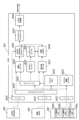
次に、上記のような外観構成からなるパチンコ遊技機1内に設けられる遊技の進行状況に応じて電子制御を行う制御装置を、図6を用いて説明する。この制御装置は、図6に示すように、遊技動作全般の制御を司る主制御基板60と、その主制御基板60からの制御コマンドに基づいて遊技球を払出す払出制御基板70と、画像と光と音についての制御を行うサブ制御基板80とで主に構成されている。
<Description of the control device>
Next, a control device that performs electronic control according to the progress of a game provided in the
<主制御基板に関する説明>
主制御基板60は、主制御CPU600aと、一連の遊技制御手順を記述した遊技プログラム等を格納した主制御ROM600bと、作業領域やバッファメモリ等として機能する主制御RAM600cとで構成されたワンチップマイクロコンピュータ600と、低確時(当たり抽選確率が通常の低確率状態)に幾らの賞球がされたかの比率等に関する内容の表示(性能表示)、及び、遊技者に有利な特別遊技状態を発生させる確率の設定内容の表示を兼用する7セグメントからなる計測・設定表示装置610と、RAMクリアスイッチ620と、設定キースイッチ630と、を主に搭載している。
<Description on the main control board>
The
そして、このように構成される主制御基板60には、払出モータMを制御して遊技球を払出す払出制御基板70が接続されている。そしてさらには、特別図柄1始動口44への入賞を検出する特別図柄1始動口スイッチ44aと、特別図柄2始動口45への入賞を検出する特別図柄2始動口スイッチ45aと、普通図柄始動口47の通過を検出する普通図柄始動口スイッチ47aと、一般入賞口48(右上一般入賞口48a,左上一般入賞口48b,左中一般入賞口48c,左下一般入賞口48d)への入賞を検出する右上一般入賞口スイッチ48a1,左上一般入賞口スイッチ48b1,左中一般入賞口スイッチ48c1,左下一般入賞口スイッチ48d1と、開閉扉46aによって開放又は閉止される大入賞口(図示せず)の入賞を検出する大入賞口スイッチ46cと、発射ハンドル16にて遊技領域40に発射された遊技球と同数の遊技球を検出可能なアウト口スイッチ49aとが接続されている。またさらには、開閉部材45bの動作を制御する普通電動役物ソレノイド45cと、開閉扉46aの動作を制御する特別電動役物ソレノイド46bと、特別図柄1表示装置50aと、特別図柄2表示装置50bと、普通図柄表示装置51と、7セグメント表示装置52aと、ラウンドランプ52bと、右打ち報知ランプ52cと、が接続されている。
A
このように構成される主制御基板60は、特別図柄1始動口スイッチ44a又は特別図柄2始動口スイッチ45aあるいは普通図柄始動口スイッチ47aからの信号を主制御CPU600aにて受信すると、遊技者に有利な特別遊技状態を発生させるか(いわゆる「当たり」)、あるいは、遊技者に有利な特別遊技状態を発生させないか(いわゆる「ハズレ」)の抽選を行い、その抽選結果である当否情報に応じて特別図柄の変動パターンや停止図柄あるいは普通図柄の表示内容を決定し、その決定した情報を特別図柄1表示装置50a又は特別図柄2表示装置50bあるいは普通図柄表示装置51に送信する。これにより、特別図柄1表示装置50a又は特別図柄2表示装置50bあるいは普通図柄表示装置51に抽選結果が表示されることとなる。そしてさらに、主制御基板60、すなわち、主制御CPU600aは、その決定した情報を含む演出制御コマンドDI_CMDを生成し、サブ制御基板80に送信する。なお、主制御基板60、すなわち、主制御CPU600aが、特別図柄1始動口スイッチ44a、特別図柄2始動口スイッチ45a、右上一般入賞口スイッチ48a1、左上一般入賞口スイッチ48b1、左中一般入賞口スイッチ48c1、左下一般入賞口スイッチ48d1、大入賞口スイッチ46cからの信号を受信した場合は、遊技者に幾らの遊技球を払い出すかを決定し、その決定した情報を含む払出制御コマンドPAY_CMDを払出制御基板70に送信することで、払出制御基板70が遊技者に遊技球を払出すこととなる。
The
また、抽選を行った結果、普通図柄の抽選に当選した場合、開閉部材45bが所定回数、所定時間開放するように普通電動役物ソレノイド45cが駆動制御され、特別図柄の抽選に当選した場合、特別電動役物ソレノイド46bが大入賞口(図示せず)を開放するように制御される。
As a result of the lottery, when the lottery for the normal pattern is won, the normal
一方、主制御基板60、すなわち、主制御CPU600aは、特別図柄1始動口スイッチ44a、特別図柄2始動口スイッチ45a、右上一般入賞口スイッチ48a1、左上一般入賞口スイッチ48b1、左中一般入賞口スイッチ48c1、左下一般入賞口スイッチ48d1、大入賞口スイッチ46cからの信号を受信する毎に、賞球数を計測し、アウト口スイッチ49aからの信号を受信する毎に、排出された遊技球の総数を計測する。そして、主制御基板60、すなわち、主制御CPU600aは、この計測した賞球数及び排出された遊技球の総数に基づき、低確時に幾らの賞球がされたかの比率等に関する内容(性能表示)を計測・設定表示装置610に出力する。これにより、計測・設定表示装置610に低確時に幾らの賞球がされたかの比率等に関する内容(性能表示)が表示されることとなる。
On the other hand, the
さらに、計測・設定表示装置610は、遊技者に有利な特別遊技状態を発生させる確率の設定内容を、例えば、「1」~「6」の6段階で表示することができるようになっている。しかして、このような設定内容を変更するにあたっては、設定キースイッチ630に専用キーを挿入し、ONされると、RAMクリアスイッチ620にて、遊技者に有利な特別遊技状態を発生させる確率の設定内容を例えば「1」~「6」の6段階で設定変更することができるようになっている(例えば、設定「6」が、遊技者に有利な特別遊技状態を発生させる確率が最も高く、設定「1」が、遊技者に有利な特別遊技状態を発生させる確率が最も低くなっている)。そして、その設定変更内容は、計測・設定表示装置610に表示され、設定変更内容が確定すると、7セグメントの右下側にあるドットが点灯し、設定内容が確定したことが表示されるようになっている。
Furthermore, the measurement/
他方、RAMクリアスイッチ620は、設定キースイッチ630に専用キーを挿入し、ONされた場合以外に、RAMクリアスイッチ620が押下されると、主制御RAM600c(図6参照)のメモリ領域は全てクリアされず、一部のメモリ領域のみクリアされるようになっている。すなわち、主制御RAM600cは、図7(a)に示すように、メモリ空間アドレス0000H番地~0200H番地のうち、メモリ空間アドレス0000H番地~0100H番地までが、抽選処理等の遊技処理時の作業領域等として使用される通常用RAM領域600caで、メモリ空間アドレス0100H番地~0110H番地までが、未使用領域600cbで、メモリ空間アドレス0110H番地~0130H番地までが、抽選処理等の遊技処理時に使用される通常用スタック領域600ccで、メモリ空間アドレス0130H番地~0150H番地までが、未使用領域600cdで、メモリ空間アドレス0150H番地~0190H番地までが、主制御基板60、すなわち、主制御CPU600にて計測した賞球数,非入賞数を含む遊技領域40に発射された遊技球の総数等を記憶する計測用RAM領域600ceで、メモリ空間アドレス0190H番地~01E0H番地までが、未使用領域600cfで、メモリ空間アドレス01E0H番地~0200H番地までが、賞球数,非入賞数を含む遊技領域40に発射された遊技球の総数等を計測する等の際に使用される計測用スタック領域600cgで構成されている。
On the other hand, when the RAM
かくして、このように構成された主制御RAM600cは、RAMクリアスイッチ620が押下された際、主制御RAM600cの計測用RAM領域600ce,計測用スタック領域600cgはクリアされず、通常用RAM領域600ca,通常用スタック領域600ccがクリアされるようになっている。しかして、このようにすれば、計測した賞球数,非入賞数を含む遊技領域40に発射された遊技球の総数等が誤ってクリアされる事態を防止することができる。なお、本実施形態においては、RAMクリアスイッチ620が押下された際、通常用RAM領域600ca,通常用スタック領域600ccがクリアされる例を示したが、それに限らず、未使用領域600cb,600cdを含めて、メモリ空間アドレス0000H番地~0150H番地までクリアされるようにしてもよい。
Thus, in the
また、通常用RAM領域600ca,通常用スタック領域600cc,計測用RAM領域600ce,計測用スタック領域600cgの各領域を下1桁が0から始まる番地から開始し、通常用RAM領域600caと通常用スタック領域600ccとの間に未使用領域600cbを設け、又、通常用スタック領域600ccと計測用RAM領域600ceとの間に未使用領域600cdを設け、さらに、計測用RAM領域600ceと計測用スタック領域600cgとの間に未使用領域600cfを設けることによって、領域毎の区別をつけるようにしている。これにより、プログラムが暴走した際に、他の領域に影響が出ないようにすることができる。 The normal RAM area 600ca, the normal stack area 600cc, the measurement RAM area 600ce, and the measurement stack area 600cg are each started from an address whose last digit is 0, and the normal RAM area 600ca and the normal stack are An unused area 600cb is provided between the area 600cc, an unused area 600cd is provided between the normal stack area 600cc and the measurement RAM area 600ce, and a measurement RAM area 600ce and measurement stack area 600cg are provided. By providing an unused area 600cf between . This prevents other areas from being affected when the program runs out of control.
一方、主制御ROM600bは、図7(b)に示すように、メモリ空間アドレス8000H番地~A800H番地のうち、メモリ空間アドレス8000H番地~8B90H番地までが、抽選処理等の遊技処理時に使用されるプログラムが格納されている通常用プログラム領域600baで、メモリ空間アドレス8B90H番地~9000H番地までが、未使用領域600bbで、メモリ空間アドレス9000H番地~9A00H番地までが、抽選処理等の遊技処理時に使用されるデータが格納されている通常用データ領域600bcで、メモリ空間アドレス9A00H番地~9C00H番地までが、未使用領域600bdで、メモリ空間アドレス9C00H番地~A010H番地までが、賞球数,非入賞数を含む遊技領域40に発射された遊技球の総数等を計測する際に使用されるプログラムが格納されている計測用プログラム領域600beで、メモリ空間アドレスA010H番地~A200H番地までが、未使用領域600bfで、メモリ空間アドレスA200H番地~A320H番地までが、賞球数,非入賞数を含む遊技領域40に発射された遊技球の総数等を計測する際に使用されるデータが格納されている計測用データ領域600bgで、メモリ空間アドレスA320H番地~A780H番地までが、未使用領域600bhで、メモリ空間アドレスA780H番地~A800H番地までが、ベクタテーブル領域600biで構成されている。
On the other hand, as shown in FIG. 7B, the
しかして、このように構成された主制御RAM600cは、通常用プログラム領域600ba,通常用データ領域600bc,計測用プログラム領域600be,計測用データ領域600bg,ベクタテーブル領域600biの各領域を下1桁が0から始まる番地から開始し、通常用プログラム領域600baと通常用データ領域600bcとの間に未使用領域600bbを設け、又、通常用データ領域600bcと計測用プログラム領域600beとの間に未使用領域600bdを設け、さらに、計測用プログラム領域600beと計測用データ領域600bgとの間に未使用領域600bfを設け、そしてさらに、計測用データ領域600bgとベクタテーブル領域600biとの間に未使用領域600bhを設けることによって、領域毎の区別をつけるようにしている。これにより、プログラムが暴走した際に、他の領域に影響が出ないようにすることができる。
The
<払出制御基板に関する説明>
払出制御基板70は、上記主制御基板60(主制御CPU600a)からの払出制御コマンドPAY_CMDを受信し、その受信した払出制御コマンドPAY_CMDに基づいて払出モータ信号を生成する。そして、その生成した払出モータ信号にて、払出モータMを制御し、遊技者に遊技球を払出す。そしてさらに、払出制御基板70は、遊技球の払出動作を示す賞球計数信号や払出動作の異常に係るステータス信号を送信し、遊技者の操作に応答して遊技球を発射させる発射制御基板71の動作を開始又は停止させる発射制御信号を送信する処理を行う。
<Description on payout control board>
The
<サブ制御基板に関する説明>
サブ制御基板80は、上記主制御基板60(主制御CPU600a)からの演出制御コマンドDI_CMDを受けて各種演出を実行制御すると共に、液晶表示装置41に表示される表示画像を制御するサブ制御CPU800aと、演出制御手順を記述した制御プログラムや図8に示す演出シナリオテーブルPR_TBL等が格納されているサブ制御ROM800bと、作業領域やバッファメモリ等として機能するサブ制御RAM800cとで構成されたサブワンチップマイコン800を搭載している。
<Description on the sub-control board>
The
またさらに、サブ制御基板80は、所望のBGMや効果音を生成する音LSI801と、作業領域やバッファメモリ等として機能する音RAM802と、サブワンチップマイコン800の指示に基づき液晶表示装置41に表示される画像データを生成するVDP803と、動画圧縮データを伸張する作業領域と、液晶表示装置41に表示される画像データを一時的に保存するフレームバッファ領域とで構成されるDDR2SDRAM804と、静止画圧縮データと動画圧縮データのCGデータと、BGMや効果音等の音データと、が予め格納されている遊技ROM805と、が搭載されている。なお、静止画とは、いわゆるスプライト画像であって、文字等のテキストデータや背景画像、あるいは、特別図柄等、単一の画像を示すものである。また、動画とは、連続的に変化する複数枚(複数フレーム分)の静止画の集合を意味し、液晶表示装置41に複数枚の静止画が連続して描画されることで、円滑な動作が再現されるものである。
Furthermore, the
このように構成されるサブ制御基板80には、ランプ演出効果を現出するLEDランプ等の装飾ランプが搭載されている装飾ランプ基板90が接続され、さらに、内蔵されているランプ(図示せず)点灯時に遊技者が押下することにより演出効果を変化させることができる押しボタン式の演出ボタン装置13が接続され、BGMや効果音等を発するスピーカ17が接続されている。そしてさらに、サブ制御基板80には、遊技の進行に伴い所定の演出動作を行う可動役物装置43が接続され、特別図柄1,特別図柄2が変動中、あるいは、当該特別図柄1,特別図柄2の当りハズレの情報を遊技者に知らせるための識別ランプ装置50Aが接続され、各種設定が可能な設定ボタン15が接続され、液晶表示装置41が接続されている。なお、言うまでもないが、この装飾ランプ基板90には、上・左・右・左上可動役物43a~43dに配置されている装飾ランプも搭載されている。
The
かくして、このように構成されるサブ制御基板80は、主制御基板60(主制御CPU600a)より送信される抽選結果に基づく特別図柄変動パターン、現在の遊技状態、始動保留球数、抽選結果に基づき停止させる装飾図柄等に必要となる基本情報を含んだ演出制御コマンドDI_CMDをサブ制御CPU800aにて受信する。そして、サブ制御CPU800aは、受信した演出制御コマンドDI_CMDに対応した演出パターンを、サブ制御ROM800b内に予め格納しておいた多数の演出パターンの中から抽選により決定し、その決定した演出パターンを実行指示する制御信号をサブ制御RAM800c内に一時的に格納する。
Thus, the
サブ制御CPU800aは、サブ制御RAM800cに格納しておいた演出パターンを実行指示する制御信号のうち、音に関する制御信号を音LSI801に送信する。これを受けて音LSI801は、当該制御信号に対応する音データを遊技ROM805又は音RAM802より読み出し、スピーカ17に出力する。これにより、スピーカ17より上記決定された演出パターンに対応したBGMや効果音が発せられることとなる。
The
またサブ制御CPU800aは、サブ制御RAM800cに格納しておいた演出パターンを実行指示する制御信号のうち、光に関する制御信号を装飾ランプ基板90に送信する。これにより、装飾ランプ基板90が、ランプ演出効果を現出するLEDランプ等の装飾ランプを点灯又は消灯する制御を行うため、上記決定された演出パターンに対応したランプ演出が実行されることとなる。
Further, the
そしてサブ制御CPU800aは、サブ制御RAM800cに格納しておいた演出パターンを実行指示する制御信号のうち、画像に関するコマンドリストをVDP803に送信する。これにより、VDP803が、当該コマンドリストに基づく画像を表示させるように画像データを生成し、その生成した画像データを液晶表示装置41に送信することにより、上記決定された演出パターンに対応した画像が液晶表示装置41に表示されることとなる。
Then, the
さらにサブ制御CPU800aは、サブ制御RAM800cに格納しておいた演出パターンを実行指示する制御信号のうち、可動役物に関する制御信号を可動役物装置43に送信する。これにより、可動役物装置43は、上記決定された演出パターンに対応した可動をすることとなる。
Further, the
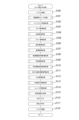
<演出シナリオテーブルの説明>
ここで、サブ制御ROM800b内に格納されている演出シナリオテーブルPR_TBLについて、図8を用いて詳しく説明する。図8(a)に示すように、演出シナリオテーブルPR_TBLには、サブ制御CPU800aにて決定された演出パターンに対応した複数の演出シナリオデータPS_DATAが格納されている。この演出シナリオデータPS_DATAには、液晶表示装置41に表示させる画像データを描画する際に使用される1レイヤ毎のデータである1レイヤデータPS_DATA1が複数格納されている。この1レイヤデータPS_DATA1には、図8(b)に示すように、1フレーム~10フレーム描画する等のフレームデータPS_DATA10と、制御コードデータPS_DATA11と、液晶表示装置41に表示させる際の位置を示す座標データPS_DATA12と、画像の変形,拡大,縮小,透過度等の画素計算データPS_DATA13と、画像の拡大,縮小を示す拡縮データPS_DATA14とが格納されている。そしてさらには、スピーカ17より発せられる音を示す音データPS_DATA15と、可動役物装置43を可動させるための可動役物データPS_DATA16と、ランプ演出効果を現出するLEDランプ等の装飾ランプを点灯又は消灯させるためのランプデータPS_DATA17とが格納されている。
<Description of production scenario table>
Here, the effect scenario table PR_TBL stored in the
また、制御コードデータPS_DATA11は、図8(c)に示す制御テーブルCH_TBLが格納されているサブ制御ROM800bのアドレス番地が格納されており、そのアドレス番地に示す内容のデータが参照されることとなる。すなわち、制御テーブルCH_TBLは、図8(c)に示すように、複数のキャラ用データCH_DATAが格納されており、このキャラ用データCH_DATAには、静止画か動画かを示すデータPS_DATA110と、遊技ROM805のアドレス番地を示すアドレスデータPS_DATA111と、画像サイズを示す画像サイズデータPS_DATA112と、設定ボタン15の連打演出又は演出ボタン装置13の押下演出の有効/無効を示すボタンデータPS_DATA113と、可動役物装置43の可動を開始するタイミングを示す可動役物タイミングデータPS_DATA114と、が格納されている。これにより、制御コードデータPS_DATA11は、図8(c)に示す制御テーブルCH_TBLに格納されている複数のキャラ用データCH_DATAから、一つのキャラ用データCH_DATAを参照することとなる。なお、演出シナリオデータPS_DATAに格納されている1レイヤデータPS_DATA1は、優先順位が低いものから順に格納されており、この優先順位が低い位置に、図8(c)に示す制御テーブルCH_TBLより動画を示すデータPS_DATA110が参照されるような制御コードデータPS_DATA11が格納され、優先順位が高い位置に、図8(c)に示す制御テーブルCH_TBLより静止画を示すデータPS_DATA110が参照されるような制御コードデータPS_DATA11が格納されている。
The control code data PS_DATA11 stores the address address of the
<VDPの説明>
一方、液晶表示装置41に表示させる画像データを生成するVDP803は、図9に示すように構成されている。
<Description of VDP>
On the other hand, the
図9に示すように、VDP803は、DDR2SDRAM804用のインターフェース回路(I/F)8030と、遊技ROM805用のインターフェース回路(I/F)8031と、サブワンチップマイコン800用のインターフェース回路(I/F)8032とが内蔵されている。そしてさらに、VDP803は、サブワンチップマイコン800(サブ制御CPU800a)からインターフェース回路(I/F)8032を介してアクセスされるシステム制御レジスタ8033と、コマンドリストを記憶するコマンドメモリ8034と、コマンドリストを解析するコマンドパーサ8035と、遊技ROM805内のデータの読出しを制御するCGメモリコントローラ8036と、静止画圧縮データをデコードする静止画デコーダ8037と、動画圧縮データをデコードする動画デコーダ8038と、静止画デコーダ8037及び動画デコーダ8038にてデコード(伸張)された画像について、拡大・縮小・回転・移動などのアフィン変換や投影変換などを実行するジオメトリエンジン8039と、内蔵VRAM8040と、液晶表示装置41に表示される画像データを生成するレンダリングエンジン8041と、DDR2SDRAM804内のデータの読出し、及び、DDR2SDRAM804内へのデータの書き込みを制御するDDR2SDRAMコントローラ8042と、液晶表示装置41へレンダリングエンジン8041にて生成された画像データを表示させるタイミング等の制御を行うディスプレイコントローラ8043と、液晶表示装置41へ画像データを送信するにあたり、LVDS(Low Voltage Differential Signaling)形式で送信するLVDS送信部8044とで構成されている。
As shown in FIG. 9, the
システム制御レジスタ8033は、VDP803に対する指示データなどをサブワンチップマイコン800(サブ制御CPU800a)が書き込むレジスタ群と、VDP803の動作状態などを示す情報をサブワンチップマイコン800(サブ制御CPU800a)が読み出すレジスタ群とに大別される。これにより、サブワンチップマイコン800(サブ制御CPU800a)は、所定の入力レジスタに必要な設定値を書き込むことで、VDP803を適宜動作させ、必要な出力レジスタの値を参照することで、VDP803の動作状態を把握することが可能となる。
The
一方、コマンドメモリ8034は、コマンドリストが記憶されるもので、このコマンドリストは、サブワンチップマイコン800(サブ制御CPU800a)よりインターフェース回路(I/F)8032を介して送信されてくるものである。より具体的に説明すると、サブワンチップマイコン800(サブ制御CPU800a)は、主制御基板60(主制御CPU600a)にて受信した演出制御コマンドDI_CMDに対応した演出パターンを、サブ制御ROM800b内に予め格納しておいた多数の演出パターンの中から抽選により決定し、その決定した演出パターンに基づいて、コマンドリストを作成し、インターフェース回路(I/F)8032を介してコマンドメモリ8034に送信する。これを受けて、コマンドメモリ8034は、そのコマンドリストを記憶するというものである。
On the other hand, the
他方、コマンドパーサ8035は、上記コマンドメモリ8034に記憶されているコマンドリストを解析し、このコマンドリスト解析によって、毎フレーム描画動作が実行されることとなる。すなわち、静止画デコーダ8037は、コマンドパーサ8035によるコマンドリストの解析結果に基づいて、CGメモリコントローラ8036を用いて、アドレスデータPS_DATA111(図8(c)参照)にて示す遊技ROM805のアドレス番地より静止画圧縮データを読出し、その読み出した静止画圧縮データをデコード(伸張)する。そして、デコードされた静止画データは、内蔵VRAM8040内に一時保存されることとなる。
On the other hand, the
一方、動画デコーダ8038は、コマンドパーサ8035によるコマンドリストの解析結果に基づいて、CGメモリコントローラ8036を用いて、アドレスデータPS_DATA111(図8(c)参照)にて示す遊技ROM805のアドレス番地より動画圧縮データを読出し、その読み出した動画圧縮データをデコード(伸張)する。そして、デコードされた動画データは、DDR2SDRAM804内に一時保存されることとなる。
On the other hand, based on the analysis result of the command list by the
このようにして、デコード(伸張)された静止画や動画(1フレーム分の動画)は、コマンドパーサ8035によるコマンドリストの解析結果、すなわち、図8(b)に示す各種データ(フレームデータPS_DATA10,座標データPS_DATA12,画素計算データPS_DATA13,拡縮データPS_DATA14)に基づいて、ジオメトリエンジン8039が、拡大・縮小・回転・移動などのアフィン変換や、投影変換などの処理を施し、その処理が施された静止画データは、内蔵VRAM8040内に格納され、動画データは、DDR2SDRAM804内に格納されることとなる。
In this way, the decoded (decompressed) still image and moving image (moving image for one frame) are converted into the analysis result of the command list by the
そして、その後、レンダリングエンジン8041が機能して、DDR2SDRAM804内に格納されている動画データが、DDR2SDRAMコントローラ8042によって読み出され、レンダリングエンジン8041によって、動画データが描画される。次いで、内蔵VRAM8040より静止画データが読み出され、静止画データが描画される。これにより、動画データ上に静止画データが上書き描画されることにより、液晶表示装置41に表示される画像データが生成されることとなる。なお、この生成された画像データは、DDR2SDRAMコントローラ8042によって、DDR2SDRAM804内のフレームバッファ領域内に書き込まれることとなる。
After that, the
かくして、フレームバッファ領域内に書き込まれた画像データは、ディスプレイコントローラ8043によって、DDR2SDRAMコントローラ8042より読み出され、LVDS送信部8044によって液晶表示装置41に送信されることとなる。これにより、液晶表示装置41にレンダリングエンジン8041によって生成された画像データが表示されることとなる。
Thus, the image data written in the frame buffer area is read out from the
ところで、液晶表示装置41に表示される画像データは1フレーム毎に更新されるが、この1フレームの表示動作が終わったことをサブワンチップマイコン800(サブ制御CPU800a)が把握できるように、図6,図9に示すVSYNC(垂直同期信号)を割込み信号としてVDP803からサブ制御CPU800aに対して送信するようにしている。これにより、サブ制御CPU800aは、1フレーム分の画像データが液晶表示装置41に表示されたことを把握することができる。なお、このVSYNC割込み信号は、例えば、33ms毎に発生するようにしている。
By the way, the image data displayed on the liquid
<電源基板の説明>
ところで、上記説明した各基板への電源供給は、図6に示す電源基板130より供給されている。この電源基板130は、電圧生成部1300と、電圧監視部1310と、システムリセット生成部1320とを含んで構成されている。この電圧生成部1300は、遊技店に設置された図示しない変圧トランスから供給される外部電源である交流電圧AC24Vを受けて複数種類の直流電圧を生成するもので、その生成された直流電圧は、図示はしないが各基板に供給されている。
<Description of power supply board>
By the way, the power supply to each board described above is supplied from the
また、電圧監視部1310は、上記交流電圧AC24Vの電圧を監視するもので、この電圧が遮断されたり、停電が発生したりして電圧異常を検出した場合に電圧異常信号ALARMを主制御基板60に出力するものである。なお、電圧異常信号ALARMは、電圧異常時には「L」レベルの信号を出力し、正常時には「H」レベルの信号を出力する。
In addition, the
また、一方、システムリセット生成部1320は、電源投入時のシステムリセット信号RSTを生成するもので、その生成されたシステムリセット信号RSTは、各基板に出力されている。
On the other hand, the
<装飾図柄と常駐図柄の説明>
次に、装飾図柄と常駐図柄について、図10~図27を参照して具体的に説明する。
<Description of decorative design and resident design>
Next, decorative patterns and resident patterns will be specifically described with reference to FIGS. 10 to 27. FIG.
図10(a)に示すように、装飾図柄は、液晶表示装置41の画像P1Aに示すように、画面中央に大きく表示され、左装飾図柄(画像P1Aa参照)と、中装飾図柄(画像P1Ab参照)と、右装飾図柄(画像P1Ac参照)と、で構成されている。図示では、左装飾図柄(画像P1Aa)が「7」で停止し、中装飾図柄(画像P1Ab参照)が「6」で停止し、右装飾図柄(画像P1Ac)が「7」で停止しているリーチハズレの状態で停止している。
As shown in FIG. 10(a), the decorative patterns are displayed large in the center of the screen as shown in the image P1A of the liquid
一方、常駐図柄は、図10(a)に示すように、液晶表示装置41の画像P2Aに示すように、画面右下端に小さく表示されるものである。この常駐図柄は、変動表示される装飾図柄で示す数字を縮小したものであり、原則として装飾図柄に同期して変動表示されるものである。具体的には、常駐図柄は、左常駐図柄(画像P2Aa参照)と、中常駐図柄(画像P2Ab参照)と、右常駐図柄(画像P2Ac参照)と、で構成されている。この左常駐図柄(画像P2Aa参照)は、左装飾図柄(画像P1Aa参照)に対応し、図示では、「7」で停止している。そして、中常駐図柄(画像P2Ab参照)は、中装飾図柄(画像P1Ab参照)に対応し、図示では、「6」で停止している。そしてさらに、右常駐図柄(画像P2Ac参照)は、右装飾図柄(画像P1Ac参照)に対応し、図示では、「7」で停止している。
On the other hand, the resident pattern is displayed in a small size at the lower right corner of the screen, as shown in the image P2A of the liquid
かくして、上記のような装飾図柄と常駐図柄が液晶表示装置41に表示されている状態で、図10(b),(c)に示すように、装飾図柄(画像P3A,P5A参照)が変動表示されていくと、それに合わせて、常駐図柄(画像P4A,P6A参照)も変動表示されていくこととなる。具体的には、図10(a)に示す左常駐図柄(画像P2Aa参照)は、変動表示されると、図10(b)に示す画像P4Aaに示すように、+1された左常駐図柄に切り替わって表示され、さらに、図10(c)に示す画像P6Aaに示すように、+1された左常駐図柄に切り替わって表示されていくこととなる。そして、図10(a)に示す中常駐図柄(画像P2Ab参照)は、変動表示されると、図10(b)に示す画像P4Abに示すように、+1された中常駐図柄に切り替わって表示され、さらに、図10(c)に示す画像P6Abに示すように、+1された中常駐図柄に切り替わって表示されていくこととなる。そしてさらに、図10(c)に示す右常駐図柄(画像P2Ac参照)は、変動表示されると、図10(b)に示す画像P4Acに示すように、+1された右常駐図柄に切り替わって表示され、さらに、図10(c)に示す画像P6Abに示すように、+1された右常駐図柄に切り替わって表示されていくこととなる。
Thus, in a state in which the decorative patterns and resident patterns as described above are displayed on the liquid
しかしながら、上記のように常駐図柄を変動させると、図10に示すように、リーチハズレ後の変動では、左常駐図柄と右常駐図柄とが同期して変動することとなるため、リーチ演出が再び発生するのではないかと遊技者に誤解を与える可能性があるという問題があった。また、大当たり後の変動では、左常駐図柄と中常駐図柄と右常駐図柄とが全て同じ図柄であるため、全回転状態で変動しているように見え、もって、大当たり演出が再び発生するのではないかと遊技者に誤解を与える可能性があるという問題があった。 However, if the resident pattern is changed as described above, as shown in FIG. 10, the left resident pattern and the right resident pattern fluctuate synchronously in the fluctuation after the reach loss, so the ready-to-win effect occurs again. There is a problem that there is a possibility of giving the player a misunderstanding that they are not going to do it. In addition, after the big hit, the left resident pattern, the middle resident pattern and the right resident pattern are all the same pattern, so it looks like it fluctuates in the full rotation state, and as a result, the big win effect will occur again. There is a problem that there is a possibility of giving the player a misunderstanding.
そこで、本実施形態においては、上記のような問題を解決すべく、以下のような処理を行っている。すなわち、図11(a)に示すように、液晶表示装置41に、装飾図柄(画像P1A参照)と、常駐図柄(画像P2A参照)が、リーチハズレ状態で停止した後、図12に示すタイミングT1A時、主制御基板60(主制御CPU600a)より演出制御コマンドDI_CMDとして、変動パターンコマンドが、サブ制御CPU800aに送信される。これを受けて、サブ制御CPU800aは、図12に示すタイミングT1A時に決定された変動パターンを実行指示する制御信号をサブ制御RAM800c内に一時的に格納する。これにより、サブ制御CPU800aは、サブ制御RAM800c内に格納しておいた演出パターンを実行指示する制御信号のうち、画像(映像)に関するコマンドリストをVDP803に送信する。これを受けて、VDP803が、当該コマンドリストに基づく画像を表示させるように画像(映像)データを生成し、その生成した画像(映像)データを液晶表示装置41に送信する。これにより、装飾図柄、常駐図柄が変動した映像が液晶表示装置41に表示されることとなる。
Therefore, in the present embodiment, the following processing is performed in order to solve the above problems. That is, as shown in FIG. 11(a), after the decorative pattern (see image P1A) and the resident pattern (see image P2A) on the liquid
具体的には、図11(b)に示すように、装飾図柄(画像P10A参照)がスクロールして変動を開始した際、常駐図柄を、予め定められた常駐図柄(画像P11A参照)に瞬時に切り替える。すなわち、図11(a)に示すように「7」と表示されている左常駐図柄(画像P2Aa参照)を、図11(b)に示すように、「1」に切り替え(画像P11Aa参照)、図11(a)に示すように「6」と表示されている中常駐図柄(画像P2Ab参照)を、図11(b)に示すように、「2」に切り替え(画像P11Ab参照)、図11(a)に示すように「7」と表示されている右常駐図柄(画像P2Ac参照)を、図11(b)に示すように、「3」に切り替え(画像P11Ac参照)るようにする。そして、予め定められた常駐図柄(画像P11A参照)に瞬時に切り替えた後、図11(c)~(e)に示すように、切り替わった常駐図柄(画像P11A参照)から常駐図柄は、変動表示されていくこととなる。すなわち、瞬時に切り替わった図11(b)に示す左常駐図柄(画像P11Aa参照)は、図11(c)に示す画像P12Aaに示すように、+1された左常駐図柄に切り替わって表示され、さらに、図11(d)に示す画像P13Aaに示すように、+1された左常駐図柄に切り替わって表示され、そしてさらに、図11(d)に示す画像P14Aaに示すように、+1された左常駐図柄に切り替わって表示されていくこととなる。また、瞬時に切り替わった図11(b)に示す中常駐図柄(画像P11Ab参照)は、図11(c)に示す画像P12Abに示すように、+1された中常駐図柄に切り替わって表示され、さらに、図11(d)に示す画像P13Abに示すように、+1された中常駐図柄に切り替わって表示され、そしてさらに、図11(d)に示す画像P14Abに示すように、+1された中常駐図柄に切り替わって表示されていくこととなる。また一方、瞬時に切り替わった図11(b)に示す右常駐図柄(画像P11Ac参照)は、図11(c)に示す画像P12Acに示すように、+1された右常駐図柄に切り替わって表示され、さらに、図11(d)に示す画像P13Acに示すように、+1された右常駐図柄に切り替わって表示され、そしてさらに、図11(d)に示す画像P14Acに示すように、+1された右常駐図柄に切り替わって表示されていくこととなる。なお、装飾図柄は、図11(c)に示す画像P15A、図11(d)に示す画像P16A、図11(e)に示す画像P17Aに示すように、スクロールして変動していくこととなる。かくして、このように、装飾図柄がスクロールして変動することで、画面中央の停止位置に表示される図柄が順次切り替わることとなる。 Specifically, as shown in FIG. 11(b), when the decorative design (see image P10A) scrolls and starts to fluctuate, the resident design is instantly changed to a predetermined resident design (see image P11A). switch. That is, the left resident symbol (see image P2Aa) displayed as "7" as shown in FIG. 11(a) is switched to "1" (see image P11Aa) as shown in FIG. 11(b), As shown in FIG. 11(a), the middle resident pattern (see image P2Ab) displayed as "6" is switched to "2" (see image P11Ab) as shown in FIG. The right resident symbol (see image P2Ac) displaying "7" as shown in (a) is switched to "3" (see image P11Ac) as shown in FIG. 11(b). Then, after instantly switching to a predetermined resident pattern (see image P11A), as shown in FIGS. It will be done. That is, the instantly switched left resident pattern (see image P11Aa) shown in FIG. , as shown in the image P13Aa shown in FIG. 11(d), it is switched to the left resident symbol incremented by 1, and further, as shown in the image P14Aa shown in FIG. 11(d), the left resident symbol incremented by 1 is displayed. will be switched to and displayed. In addition, the instantaneously switched medium resident pattern (see image P11Ab) shown in FIG. , as shown in the image P13Ab shown in FIG. 11(d), the middle resident symbol is changed to +1 and displayed, and further, as shown in the image P14Ab shown in FIG. 11(d), the middle resident symbol is incremented by +1. will be switched to and displayed. On the other hand, the instantly switched right resident pattern (see image P11Ac) shown in FIG. Furthermore, as shown in the image P13Ac shown in FIG. 11(d), it is switched to the right resident symbol incremented by +1, and further, as shown in the image P14Ac shown in FIG. 11(d), the right resident symbol incremented by +1 is displayed. It will switch to the pattern and will be displayed. Note that the decorative pattern scrolls and changes as shown in the image P15A shown in FIG. 11(c), the image P16A shown in FIG. 11(d), and the image P17A shown in FIG. 11(e). . Thus, by scrolling and varying the decorative symbols, the symbols displayed at the stop position in the center of the screen are sequentially switched.
しかして、このように前回の停止図柄に関係なく、予め定められた図柄から常駐図柄の変動を開始するようにすれば、装飾図柄と常駐図柄に対する遊技者の誤認が無いようにすることができる。そしてさらに、常駐図柄を瞬時に切り替えるだけであるため、制御を簡素化することができる。なお、本実施形態においては、装飾図柄をスクロールして変動する例を示したが、これに限らず常駐図柄と同様に順次図柄が切り替わるようにしても良い。また、装飾図柄を停止位置において、Y軸(図示上下方向の軸)を中心とした横回転、或いは、X軸(図示左右方向の軸)を中心とした縦回転などによって変動させるようにしても良い。 Thus, by starting the variation of the resident symbols from the predetermined symbols regardless of the last stop symbol, it is possible to prevent the player from erroneously recognizing the decorative symbols and the resident symbols. . Furthermore, the control can be simplified because the resident symbols are switched instantaneously. In the present embodiment, an example in which decorative symbols are scrolled and varied is shown, but the present invention is not limited to this, and symbols may be sequentially switched in the same manner as the resident symbols. Also, at the stop position, the decorative pattern can be changed by rotating it horizontally around the Y-axis (vertical axis in the figure) or vertically around the X-axis (horizontal axis in the figure). good.
ところで、図12に示すように、タイミングT1A時、左常駐図柄、中常駐図柄、右常駐図柄ともに、高速変動することとなる。そしてさらに、常駐図柄は、装飾図柄のようにスクロールして変動するものではないため、タイミングT1A時、瞬時に図柄を切り替えても遊技者に違和感を与えることなく、切り替えることが可能となる。 By the way, as shown in FIG. 12, at timing T1A, the left resident symbols, middle resident symbols, and right resident symbols all fluctuate at high speed. Further, since the resident pattern does not fluctuate by scrolling like the decorative pattern, the pattern can be switched instantaneously at the timing T1A without making the player feel uncomfortable.
かくして、このように、図12に示すように、タイミングT1A時、常駐図柄(左常駐図柄、中常駐図柄、右常駐図柄)が高速変動し、装飾図柄(左装飾図柄、中装飾図柄、右装飾図柄)が変動を開始すると、タイミングT2A時、サブ制御CPU800aは、装飾図柄(左装飾図柄、中装飾図柄、右装飾図柄)を高速変動させるコマンドリストをVDP803に送信する。これを受けて、VDP803が、当該コマンドリストに基づく画像を表示させるように画像(映像)データを生成し、その生成した画像(映像)データを液晶表示装置41に送信する。これにより、図11(f)に示すように、装飾図柄(画像P18A参照)が高速変動している映像が液晶表示装置41に表示されることとなる。
Thus, as shown in FIG. 12, at timing T1A, the resident patterns (left resident pattern, middle resident pattern, right resident pattern) fluctuate at high speed, and decorative patterns (left decorative pattern, middle decorative pattern, right decorative pattern) are changed at high speed. pattern) starts to fluctuate, at timing T2A, the
次いで、図12に示すタイミングT3A時、サブ制御CPU800aは、左装飾図柄を減速変動させるコマンドリストをVDP803に送信する。これを受けて、VDP803が、当該コマンドリストに基づく画像を表示させるように画像(映像)データを生成し、その生成した画像(映像)データを液晶表示装置41に送信する。これにより、図11(g)に示すように、左装飾図柄(画像P19Aa参照)が減速変動している映像が液晶表示装置41に表示されることとなる。この際、VDP803は、図12に示すタイミングT1A時に決定された左装飾図柄の停止図柄に合わせるため、減速変動開始する図柄に切り替えて、液晶表示装置41に表示するようにする。具体的には、本実施形態においては、左装飾図柄の停止図柄が「2」であるため、図12に示すように、高速変動している「6」の図柄から減速変動開始する図柄「9」に切り替えて、減速変動開始している。なお、高速変動している際、装飾図柄は透過度を上げて(例えば、半透明)高速変動しているため、減速変動開始する図柄「9」に切り替えても、遊技者に違和感を与えることはない。
Next, at timing T3A shown in FIG. 12, the
かくして、このようにして、図11(g)に示すように、左装飾図柄(画像P19Aa参照)が減速変動している映像が液晶表示装置41に表示され、さらに、図11(h)に示すように、左装飾図柄(画像P20Aa参照)が減速変動している映像が液晶表示装置41に表示される。
Thus, as shown in FIG. 11(g), an image in which the left decorative pattern (see image P19Aa) is decelerating and fluctuating is displayed on the liquid
次いで、図12に示すタイミングT3Aa時、サブ制御CPU800aは、左装飾図柄を停止又は揺れ変動させるコマンドリストをVDP803に送信する。これを受けて、VDP803が、当該コマンドリストに基づく画像を表示させるように画像(映像)データを生成し、その生成した画像(映像)データを液晶表示装置41に送信する。これにより、図11(i)に示すように、左装飾図柄(画像P21Aa参照)が図12に示すタイミングT1A時に決定された左装飾図柄の停止図柄(図示では、「2」)となり、停止又は揺れ変動している映像が液晶表示装置41に表示されることとなる。
Next, at timing T3Aa shown in FIG. 12, the
次いで、図12に示すタイミングT4A時、サブ制御CPU800aは、右装飾図柄を減速変動させるコマンドリストをVDP803に送信する。これを受けて、VDP803が、当該コマンドリストに基づく画像を表示させるように画像(映像)データを生成し、その生成した画像(映像)データを液晶表示装置41に送信する。これにより、図11(j)に示すように、右装飾図柄(画像P22Ac参照)が減速変動している映像が液晶表示装置41に表示されることとなる。この際、VDP803は、図12に示すタイミングT1A時に決定された右装飾図柄の停止図柄に合わせるため、減速変動開始する図柄に切り替えて、液晶表示装置41に表示するようにする。具体的には、本実施形態においては、右装飾図柄の停止図柄が「3」であるため、図12に示すように、高速変動している「4」の図柄から減速変動開始する図柄「1」に切り替えて、減速変動開始している。なお、高速変動している際、装飾図柄は透過度を上げて(例えば、半透明)高速変動しているため、減速変動開始する図柄「1」に切り替えても、遊技者に違和感を与えることはない。
Next, at timing T4A shown in FIG. 12, the
かくして、このようにして、図11(j)に示すように、右装飾図柄(画像P22Ac参照)が減速変動している映像が液晶表示装置41に表示され、さらに、図11(k)に示すように、右装飾図柄(画像P23Ac参照)が減速変動している映像が液晶表示装置41に表示される。
Thus, in this way, as shown in FIG. 11(j), an image in which the right decorative pattern (see image P22Ac) is decelerating and fluctuating is displayed on the liquid
次いで、図12に示すタイミングT4Aa時、サブ制御CPU800aは、右装飾図柄を停止又は揺れ変動させるコマンドリストをVDP803に送信する。これを受けて、VDP803が、当該コマンドリストに基づく画像を表示させるように画像(映像)データを生成し、その生成した画像(映像)データを液晶表示装置41に送信する。これにより、図11(l)に示すように、右装飾図柄(画像P24Ac参照)が図12に示すタイミングT1A時に決定された右装飾図柄の停止図柄(図示では、「3」)となり、停止又は揺れ変動している映像が液晶表示装置41に表示されることとなる。
Next, at timing T4Aa shown in FIG. 12, the
次いで、図12に示すタイミングT5A時、サブ制御CPU800aは、中装飾図柄を減速変動させるコマンドリストをVDP803に送信する。これを受けて、VDP803が、当該コマンドリストに基づく画像を表示させるように画像(映像)データを生成し、その生成した画像(映像)データを液晶表示装置41に送信する。これにより、図11(m)に示すように、中装飾図柄(画像P25Ab参照)が減速変動している映像が液晶表示装置41に表示されることとなる。この際、VDP803は、図12に示すタイミングT1A時に決定された中装飾図柄の停止図柄に合わせるため、減速変動開始する図柄に切り替えて、液晶表示装置41に表示するようにする。具体的には、本実施形態においては、中装飾図柄の停止図柄が「5」であるため、図12に示すように、高速変動している「8」の図柄から減速変動開始する図柄「3」に切り替えて、減速変動開始している。なお、高速変動している際、装飾図柄は透過度を上げて(例えば、半透明)高速変動しているため、減速変動開始する図柄「3」に切り替えても、遊技者に違和感を与えることはない。
Next, at timing T5A shown in FIG. 12, the
かくして、このようにして、図11(m)に示すように、中装飾図柄(画像P25Ab参照)が減速変動している映像が液晶表示装置41に表示され、さらに、図11(n)に示すように、中装飾図柄(画像P26Ab参照)が減速変動している映像が液晶表示装置41に表示される。
Thus, in this manner, as shown in FIG. 11(m), an image in which the middle decorative pattern (see image P25Ab) is decelerating and fluctuating is displayed on the liquid
次いで、図12に示すタイミングT5Aa時、サブ制御CPU800aは、中装飾図柄を停止又は揺れ変動させるコマンドリストをVDP803に送信する。これを受けて、VDP803が、当該コマンドリストに基づく画像を表示させるように画像(映像)データを生成し、その生成した画像(映像)データを液晶表示装置41に送信する。これにより、図11(o)に示すように、中装飾図柄(画像P27Ab参照)が図12に示すタイミングT1A時に決定された中装飾図柄の停止図柄(図示では、「5」)となり、停止又は揺れ変動している映像が液晶表示装置41に表示されることとなる。
Next, at timing T5Aa shown in FIG. 12, the
次いで、図12に示すタイミングT6A時、主制御基板60(主制御CPU600a)より演出制御コマンドDI_CMDとして、図柄確定コマンドが、サブ制御CPU800aに送信される。これを受けて、サブ制御CPU800aは、図柄を確定させるコマンドリストをVDP803に送信する。これを受けて、VDP803が、当該コマンドリストに基づく画像を表示させるように画像(映像)データを生成し、その生成した画像(映像)データを液晶表示装置41に送信する。これにより、図11(p)に示すように、液晶表示装置41には、停止した装飾図柄(画像P28A参照)、停止した常駐図柄(画像P29A参照)が表示されることとなる。この際、常駐図柄は、変動中の図柄の更新順に関係なく、停止図柄に切り替えられることとなる。具体的には、左常駐図柄は、図12に示すように、変動中の図柄「6」から停止図柄「2」に切り替えて、図11(p)に示すように、液晶表示装置41に表示される(画像P29Aa参照)こととなる。そして、中常駐図柄は、図12に示すように、変動中の図柄「7」から停止図柄「5」に切り替えて、図11(p)に示すように、液晶表示装置41に表示される(画像P29Ab参照)こととなる。そしてさらに、右常駐図柄は、図12に示すように、変動中の図柄「8」から停止図柄「3」に切り替えて、図11(p)に示すように、液晶表示装置41に表示される(画像P29Ac参照)こととなる。
Next, at the timing T6A shown in FIG. 12, the main control board 60 (
しかして、このようにすれば、変動している常駐図柄を停止図柄に差し替えるだけでよいため、制御を簡素化することができる。またさらに、常駐図柄が次の常駐図柄に切り替わるタイミングを待つことなく、停止図柄に差し替えることができる。この際、次の常駐図柄に切り替わるまでに要するフレーム数より少ないフレーム数で切り替わることになるが、装飾図柄のようにスクロールして変動していないため、遊技者に違和感を与えることがない。そしてさらに、装飾図柄の停止状態と同じ状態で常駐図柄を停止させることができるため、装飾図柄と常駐図柄に対する遊技者の誤認が無いようにすることができる。 Thus, by doing so, it is only necessary to replace the changing resident symbols with the stationary symbols, so that the control can be simplified. Furthermore, the resident design can be replaced with the stop design without waiting for the timing of switching to the next resident design. At this time, the number of frames is smaller than the number of frames required until the next resident pattern is switched, but unlike the decorative pattern, the pattern does not fluctuate by scrolling, so that the player does not feel uncomfortable. Further, since the resident symbols can be stopped in the same state as the decorative symbols are stopped, it is possible to prevent the player from erroneously recognizing the decorative symbols and the resident symbols.
ところで、図11及び図12に示す変動開始から変動停止までの処理は、図13(a)に示す、装飾図柄用通常変動12秒変動シナリオSS_DATAと、常駐図柄用変動シナリオZS_DATAを用いて行われている。この装飾図柄用通常変動12秒変動シナリオSS_DATAは、サブ制御ROM800b内に格納されている図8(a)に示す複数の演出シナリオデータPS_DATAのうちの一つであり、常駐図柄用変動シナリオZS_DATAも、サブ制御ROM800b内に格納されている図8(a)に示す複数の演出シナリオデータPS_DATAのうちの一つである。なお、本実施形態においては、図12に示すタイミングT1A時~タイミングT6A時まで12秒で処理が終了するため、1フレーム33msとして、364フレームで処理が終わるようになっている。
By the way, the processing from the start of fluctuation to the stop of fluctuation shown in FIGS. 11 and 12 is performed using the decorative design normal fluctuation 12-second fluctuation scenario SS_DATA and the resident design fluctuation scenario ZS_DATA shown in FIG. 13(a). ing. This decorative symbol normal variation 12-second variation scenario SS_DATA is one of a plurality of effect scenario data PS_DATA shown in FIG. 8A stored in the
常駐図柄用変動シナリオZS_DATAは、図13(b)に示すように、左常駐図柄を図12に示すタイミングT1A~T6Aに示すような変動処理をするにあたって、1フレーム目であるタイミングT1A時、常駐図柄変動開始シーケンステーブルLにて処理を行い、2フレーム目から4フレーム目まで何もしない処理を設けておき、その後、5フレーム目から主制御基板60(主制御CPU600a)より送信されてくる図柄確定コマンドを受信するまで、常駐図柄変動中シーケンステーブルLにて処理を行い、主制御基板60(主制御CPU600a)より送信されてきた図柄確定コマンドを受信することによって、常駐図柄変動停止シーケンステーブルLにて処理を行うようになっている。そして、中常駐図柄を図12に示すタイミングT1A~T6Aに示すような変動処理をするにあたって、1フレーム目であるタイミングT1A時、常駐図柄変動開始シーケンステーブルCにて処理を行い、2フレーム目から4フレーム目まで何もしない処理を設けておき、その後、5フレーム目から主制御基板60(主制御CPU600a)より送信されてくる図柄確定コマンドを受信するまで、常駐図柄変動中シーケンステーブルCにて処理を行い、主制御基板60(主制御CPU600a)より送信されてきた図柄確定コマンドを受信することによって、常駐図柄変動停止シーケンステーブルCにて処理を行うようになっている。そしてさらに、右常駐図柄を図12に示すタイミングT1A~T6Aに示すような変動処理をするにあたって、1フレーム目であるタイミングT1A時、常駐図柄変動開始シーケンステーブルRにて処理を行い、2フレーム目から4フレーム目まで何もしない処理を設けておき、その後、5フレーム目から主制御基板60(主制御CPU600a)より送信されてくる図柄確定コマンドを受信するまで、常駐図柄変動中シーケンステーブルRにて処理を行い、主制御基板60(主制御CPU600a)より送信されてきた図柄確定コマンドを受信することによって、常駐図柄変動停止シーケンステーブルRにて処理を行うようになっている。なお、5フレーム目から行われる常駐図柄変動中シーケンステーブルL/C/Rにて行われる処理は、主制御基板60(主制御CPU600a)より送信されてくる図柄確定コマンドを受信するまで行われることとなる。これにより、主制御基板60(主制御CPU600a)より送信されてくる変動パターンの変動時間に関係なくなることとなり、もって、常駐図柄用変動シナリオZS_DATAだけを用意すれば良くなる。なお、現在何フレーム目か否かの判断は、変動シナリオ時に計測する変動シナリオタイマにて計測されることとなる。
As shown in FIG. 13(b), the resident symbol variation scenario ZS_DATA is the resident pattern at timing T1A, which is the first frame, when the left resident symbol is subjected to variation processing shown in timings T1A to T6A shown in FIG. Processing is performed in the pattern variation start sequence table L, processing is provided in which nothing is done from the 2nd frame to the 4th frame. Processing is performed in the resident symbol variation sequence table L until the determination command is received, and by receiving the symbol determination command transmitted from the main control board 60 (
ここで、常駐図柄変動開始シーケンステーブルL,C,R、常駐図柄変動中シーケンステーブルL,C,R、常駐図柄変動停止シーケンステーブルL,C,Rについて、図14を用いて具体的に説明する。 Here, the resident symbol variation start sequence table L, C, R, the resident symbol variation in-sequence table L, C, R, and the resident symbol variation stop sequence table L, C, R will be specifically described with reference to FIG. .
図14(a)に示すように、液晶表示装置41に表示される常駐図柄の領域は予め決められている。すなわち、左常駐図柄を表示するためのオブジェクトLx0は、常駐図柄領域L内に配置され、中常駐図柄を表示するためのオブジェクトCx0は、常駐図柄領域C内に配置され、右常駐図柄を表示するためのオブジェクトRx0は、常駐図柄領域R内に配置されている。かくして、このオブジェクトLx0、Cx0、Rx0に、図柄番号を指定してセットすることで、図柄画像が液晶表示装置41に表示されることとなる。具体的には、図柄番号:0~8(0=1図柄、1=2図柄、・・・、8=9図柄)として、変数ZuL、ZuC、ZuRに図柄番号をセットすることで、図柄画像が液晶表示装置41に表示されるようになっている。
As shown in FIG. 14(a), the resident pattern area displayed on the liquid
より詳しく説明すると、図14(b-1)に示すように、常駐図柄変動開始シーケンステーブルLでは、前変動の停止図柄に関係なく「123」から常駐図柄が変動するように、常駐図柄領域LにZuL=0がセットされている。これにより、VDP803が、図12,図13(b)に示すタイミングT1A時、図11(b)に示すように、図柄「1」である左常駐図柄(画像P11Aa参照)を液晶表示装置41に表示することとなる。
More specifically, as shown in FIG. 14(b-1), in the resident symbol variation start sequence table L, the resident symbol area L is changed so that the resident symbol changes from "123" regardless of the stop symbol of the previous variation. is set to ZuL=0. 12 and 13(b), the
そして、図14(c-1)に示すように、常駐図柄変動開始シーケンステーブルCでは、前変動の停止図柄に関係なく「123」から常駐図柄が変動するように、常駐図柄領域CにZuC=1がセットされている。これにより、VDP803が、図12,図13(b)に示すタイミングT1A時、図11(b)に示すように、図柄「2」である中常駐図柄(画像P11Ab参照)を液晶表示装置41に表示することとなる。
Then, as shown in FIG. 14(c-1), in the resident symbol variation start sequence table C, ZuC= 1 is set. As a result, at timing T1A shown in FIGS. 12 and 13(b), the
そしてさらに、図14(d-1)に示すように、常駐図柄変動開始シーケンステーブルRでは、前変動の停止図柄に関係なく「123」から常駐図柄が変動するように、常駐図柄領域RにZuR=2がセットされている。これにより、VDP803が、図12,図13(b)に示すタイミングT1A時、図11(b)に示すように、図柄「3」である右常駐図柄(画像P11Ac参照)を液晶表示装置41に表示することとなる。
Further, as shown in FIG. 14(d-1), in the resident symbol variation start sequence table R, ZuR is placed in the resident symbol area R so that the resident symbol changes from "123" regardless of the stop symbol of the previous variation. =2 is set. As a result, at timing T1A shown in FIGS. 12 and 13(b), the
次いで、図14(b-2)に示すように、常駐図柄変動中シーケンステーブルLでは、所定時間毎に、図柄を+1するために、図13(b)に示すように、セットされた時点で、ZuL=ZuL+1として常駐図柄領域LにZuLがセットされている。そして、左常駐図柄が変動していることを遊技者が認識できるように、2フレーム目から4フレーム目まで何もしない処理を設けておき、その後、最初に戻って、ZuL=ZuL+1として常駐図柄領域LにZuLがセットされるという処理が繰り返されるようになっている。これにより、VDP803が、左常駐図柄を順次切り替えることによって、図11(c)~(o)に示すように、左常駐図柄が変動している状態を液晶表示装置41に表示できることとなる。なお、常駐図柄変動中シーケンステーブルLのタイマは、変動シナリオタイマとは異なるもので、セットされた時点のフレームから1フレームとして計測しているものである。
Next, as shown in FIG. 14(b-2), in the resident symbol changing sequence table L, the symbol is incremented by +1 at predetermined time intervals, as shown in FIG. 13(b). , ZuL=
そして、図14(c-2)に示すように、常駐図柄変動中シーケンステーブルCでは、所定時間毎に、図柄を+1するために、図13(b)に示すように、セットされた時点で、ZuC=ZuC+1として常駐図柄領域CにZuCがセットされている。そして、中常駐図柄が変動していることを遊技者が認識できるように、2フレーム目から4フレーム目まで何もしない処理を設けておき、その後、最初に戻って、ZuC=ZuC+1として常駐図柄領域CにZuCがセットされるという処理が繰り返されるようになっている。これにより、VDP803が、中常駐図柄を順次切り替えることによって、図11(c)~(o)に示すように、中常駐図柄が変動している状態を液晶表示装置41に表示できることとなる。なお、常駐図柄変動中シーケンステーブルCのタイマは、変動シナリオタイマとは異なるもので、セットされた時点のフレームから1フレームとして計測しているものである。
Then, as shown in FIG. 14(c-2), in the resident symbol changing sequence table C, the symbol is incremented by 1 every predetermined time, as shown in FIG. 13(b). , ZuC=
さらに、図14(d-2)に示すように、常駐図柄変動中シーケンステーブルRでは、所定時間毎に、図柄を+1するために、図13(c)に示すように、セットされた時点で、ZuR=ZuR+1として常駐図柄領域RにZuRがセットされている。そして、右常駐図柄が変動していることを遊技者が認識できるように、2フレーム目から4フレーム目まで何もしない処理を設けておき、その後、最初に戻って、ZuR=ZuR+1として常駐図柄領域RにZuRがセットされるという処理が繰り返されるようになっている。これにより、VDP803が、右常駐図柄を順次切り替えることによって、図11(c)~(o)に示すように、右常駐図柄が変動している状態を液晶表示装置41に表示できることとなる。なお、常駐図柄変動中シーケンステーブルRのタイマは、変動シナリオタイマとは異なるもので、セットされた時点のフレームから1フレームとして計測しているものである。
Further, as shown in FIG. 14(d-2), in the resident symbol changing sequence table R, the symbol is incremented by 1 every predetermined time, as shown in FIG. 13(c). , ZuR=
次いで、図14(b-3)に示すように、常駐図柄変動停止シーケンステーブルLでは、変動中の図柄の更新順に関係なく(図14(b-2)に示す常駐図柄変動中シーケンステーブルLにおける処理タイミングに関係なく)、停止図柄に切り替えられるように、常駐図柄領域LにZuL=STOP_L1(STOP_L1=1)がセットされている。これにより、VDP803が、図12,図13(b)に示すタイミングT6A時、図11(p)に示すように、図柄「2」である左常駐図柄(画像P29Aa参照)を液晶表示装置41に表示することとなる。
Next, as shown in FIG. 14(b-3), in the resident symbol variation stop sequence table L, regardless of the order of updating the symbols during variation (in the resident symbol variation sequence table L shown in FIG. 14(b-2) ZuL=STOP_L1 (STOP_L1=1) is set in the resident design area L so that the design can be switched to the stop design regardless of the processing timing. As a result, at timing T6A shown in FIGS. 12 and 13(b), the
そして、図14(c-3)に示すように、常駐図柄変動停止シーケンステーブルCでは、変動中の図柄の更新順に関係なく(図14(c-2)に示す常駐図柄変動中シーケンステーブルCにおける処理タイミングに関係なく)、停止図柄に切り替えられるように、常駐図柄領域CにZuC=STOP_C1(STOP_C1=4)がセットされている。これにより、VDP803が、図12,図13(b)に示すタイミングT6A時、図11(p)に示すように、図柄「5」である中常駐図柄(画像P29Ab参照)を液晶表示装置41に表示することとなる。
Then, as shown in FIG. 14(c-3), in the resident symbol variation stop sequence table C, regardless of the order of updating the symbols during variation (in the resident symbol variation sequence table C shown in FIG. 14(c-2) ZuC=STOP_C1 (STOP_C1=4) is set in the resident design area C so as to switch to the stop design regardless of the processing timing. As a result, at timing T6A shown in FIGS. 12 and 13(b), the
さらに、図14(d-3)に示すように、常駐図柄変動停止シーケンステーブルRでは、変動中の図柄の更新順に関係なく(図14(d-2)に示す常駐図柄変動中シーケンステーブルRにおける処理タイミングに関係なく)、停止図柄に切り替えられるように、常駐図柄領域RにZuR=STOP_R1(STOP_R1=2)がセットされている。これにより、VDP803が、図12,図13(b)に示すタイミングT6A時、図11(p)に示すように、図柄「3」である右常駐図柄(画像P29Ac参照)を液晶表示装置41に表示することとなる。
Furthermore, as shown in FIG. 14(d-3), in the resident symbol variation stop sequence table R, regardless of the order of updating the symbols during variation (in the resident symbol variation sequence table R shown in FIG. 14(d-2) ZuR=STOP_R1 (STOP_R1=2) is set in the resident design area R so that the design can be switched to the stop design regardless of the processing timing. As a result, at timing T6A shown in FIGS. 12 and 13(b), the
かくして、このようにして、図12に示すタイミングT1A~T6Aに示す常駐図柄の変動開始から変動停止までの処理が、図13(b)に示す常駐図柄用変動シナリオZS_DATAを用いて行われることとなる。 Thus, in this way, the processing from the start of variation of the resident symbols to the stop of variation shown at timings T1A to T6A shown in FIG. 12 is performed using the resident symbol variation scenario ZS_DATA shown in FIG. 13(b). Become.
なお、本実施形態においては、常駐図柄の図柄を切り替えることにより、変動させている例を示したが、これに限らず、動画を再生させるようにしても良い。すなわち、図14(a)に示す常駐図柄領域LにVDP803を用いて、「1⇒2⇒3⇒・・・・⇒8⇒9⇒」という1から変動開始される動画を再生し、常駐図柄領域CにVDP803を用いて、「2⇒3⇒4⇒・・・・⇒9⇒1⇒」という2から変動開始される動画を再生し、常駐図柄領域RにVDP803を用いて、「3⇒4⇒5⇒・・・・⇒1⇒2⇒」という3から変動開始される動画を再生するようにしても良い。なお、常駐図柄の変動を停止させる場合は、動画の再生を停止し、停止図柄に差し替えるようにすれば良い。また、この動画は、遊技ROM805内に格納しておけばよい。
In the present embodiment, an example in which the pattern of the resident pattern is changed by switching is shown, but the present invention is not limited to this. That is, the
一方、3本の動画を用意せずとも、1本の動画「1⇒2⇒3⇒・・・・⇒8⇒9⇒」という動画を用意し、動画再生を開始させる時間を異ならせることで、1から変動開始する動画を表示、2から変動開始する動画を表示、3から変動開始する動画を表示させるようにしても良い。 On the other hand, even if you do not prepare three videos, you can prepare one video "1 ⇒ 2 ⇒ 3 ⇒ 8 ⇒ 9 ⇒" and change the time to start playing the video. , a moving image starting to fluctuate from 1, a moving image starting to fluctuate from 2, and a moving image starting to fluctuate from 3 may be displayed.
装飾図柄用通常変動12秒変動シナリオSS_DATAは、図13(c)に示すように、左装飾図柄を図12に示すタイミングT1A~T6Aに示すような変動処理をするにあたって、1フレーム目であるタイミングT1A時~80フレーム目まで、変動開始シーケンステーブルXにて処理を行い、81フレーム目であるタイミングT2A時~93フレーム目まで高速変動シーケンステーブルXにて処理を行い、94フレーム目であるタイミングT3A時~タイミングT3Aa時(図12参照)の1フレーム前まで減速変動シーケンステーブルXにて処理を行い、タイミングT3Aa時(図12参照)~363フレーム目まで揺れ変動シーケンステーブルXにて処理を行い、364フレーム目であるタイミングT6A時、変動停止シーケンステーブルXにて処理を行うようになっている。 In the normal variation 12-second variation scenario SS_DATA for decorative symbols, as shown in FIG. From time T1A to the 80th frame, processing is performed using the fluctuation start sequence table X. From time T2A, which is the 81st frame, to the 93rd frame, processing is performed using the high-speed variation sequence table X. Timing T3A, which is the 94th frame. From time to timing T3Aa (see FIG. 12), processing is performed with the deceleration variation sequence table X until one frame before, and processing is performed with the shake variation sequence table X from timing T3Aa (see FIG. 12) to the 363rd frame, At timing T6A, which is the 364th frame, processing is performed using the fluctuation stop sequence table X. FIG.
そして、中装飾図柄を図12に示すタイミングT1A~T6Aに示すような変動処理をするにあたって、1フレーム目であるタイミングT1A時~80フレーム目まで、変動開始シーケンステーブルYにて処理を行い、81フレーム目であるタイミングT2A時~273フレーム目まで高速変動シーケンステーブルYにて処理を行い、274フレーム目であるタイミングT5A時~タイミングT5Aa時(図12参照)の1フレーム前まで減速変動シーケンステーブルYにて処理を行い、タイミングT5Aa時(図12参照)~363フレーム目まで揺れ変動シーケンステーブルYにて処理を行い、364フレーム目であるタイミングT6A時、変動停止シーケンステーブルYにて処理を行うようになっている。 Then, when performing variation processing as shown in timings T1A to T6A shown in FIG. Processing is performed with the high-speed variation sequence table Y from timing T2A, which is the 274th frame, to the 273rd frame. From timing T5Aa (see FIG. 12) to the 363rd frame, processing is performed using the shake fluctuation sequence table Y. At timing T6A, which is the 364th frame, processing is performed using the fluctuation stop sequence table Y. It has become.
さらに、右装飾図柄を図12に示すタイミングT1A~T6Aに示すような変動処理をするにあたって、1フレーム目であるタイミングT1A時~80フレーム目まで、変動開始シーケンステーブルZにて処理を行い、81フレーム目であるタイミングT2A時~2183フレーム目まで高速変動シーケンステーブルZにて処理を行い、184フレーム目であるタイミングT4A時~タイミングT4Aa時(図12参照)の1フレーム前まで減速変動シーケンステーブルZにて処理を行い、タイミングT4Aa時(図12参照)~363フレーム目まで揺れ変動シーケンステーブルZにて処理を行い、364フレーム目であるタイミングT6A時、変動停止シーケンステーブルZにて処理を行うようになっている。なお、現在何フレーム目か否かの判断は、変動シナリオ時に計測する変動シナリオタイマにて計測されることとなる。 Further, in performing the variation processing shown in timings T1A to T6A shown in FIG. From timing T2A, which is the 184th frame, to the 2183rd frame, processing is performed using the high-speed fluctuation sequence table Z, and from timing T4A, which is the 184th frame, to timing T4Aa (see FIG. 12), which is one frame before the deceleration fluctuation sequence table Z. From timing T4Aa (see FIG. 12) to the 363rd frame, processing is performed using the shake fluctuation sequence table Z. At timing T6A, which is the 364th frame, processing is performed using the fluctuation stop sequence table Z. It has become. It should be noted that the judgment of the current frame is measured by the variable scenario timer that measures during the variable scenario.
ここで、変動開始シーケンステーブルX,Y,Z、高速変動シーケンステーブルX,Y,Z、減速変動シーケンステーブルX,Y,Z、揺れ変動シーケンステーブルX,Y,Z、変動停止シーケンステーブルX,Y,Zについて、図15~図19を用いて具体的に説明する。 Here, fluctuation start sequence table X, Y, Z, high speed fluctuation sequence table X, Y, Z, deceleration fluctuation sequence table X, Y, Z, shake fluctuation sequence table X, Y, Z, fluctuation stop sequence table X, Y , Z will be described in detail with reference to FIGS. 15 to 19. FIG.
図15(a-1)~(d-1)に示すように、液晶表示装置41に表示される装飾図柄の領域は予め決められている。すなわち、図15(a-1)~(d-1)に示すように、左装飾図柄を液晶表示装置41に表示するためのオブジェクトL0~L3、中装飾図柄を液晶表示装置41に表示するためのオブジェクトC0~C3、右装飾図柄を液晶表示装置41に表示するためのオブジェクトR0~R3が用意されている。そして、図15(a-1)~(d-1)に示すように、液晶表示装置41に表示される装飾図柄の表示態様として、4つのシーンが用意されている。すなわち、4つのシーンのうち、図15(a-1)に示すシーンでは、図柄変動シーンX1、図柄変動シーンY1、図柄変動シーンZ1が用意されている。この図柄変動シーンX1では、オブジェクトL0~L3のうち、液晶表示装置41には、オブジェクトL0の上半分と、オブジェクトL1と、オブジェクトL2の下半分が表示されるようになっている。そして、図柄変動シーンY1では、オブジェクトC0~C3のうち、液晶表示装置41には、オブジェクトC0の上半分と、オブジェクトC1と、オブジェクトC2の下半分が表示されるようになっている。さらに、図柄変動シーンZ1では、オブジェクトR0~R3のうち、液晶表示装置41には、オブジェクトR0の上半分と、オブジェクトL1と、オブジェクトL2の下半分が表示されるようになっている。
As shown in FIGS. 15(a-1) to (d-1), the area of the decorative pattern displayed on the liquid
一方、図15(b-1)に示すシーンでは、図柄変動シーンX2、図柄変動シーンY2、図柄変動シーンZ2が用意されている。この図柄変動シーンX2では、オブジェクトL0~L3のうち、液晶表示装置41には、オブジェクトL0の上少しと、オブジェクトL1と、ほとんどのオブジェクトL2が表示されるようになっている。そして、図柄変動シーンY2では、オブジェクトC0~C3のうち、液晶表示装置41には、オブジェクトC0の上少しと、オブジェクトC1と、ほとんどのオブジェクトC2が表示されるようになっている。さらに、図柄変動シーンZ2では、オブジェクトR0~R3のうち、液晶表示装置41には、オブジェクトR0の上少しと、オブジェクトR1と、ほとんどのオブジェクトR2が表示されるようになっている。
On the other hand, in the scene shown in FIG. 15(b-1), a symbol variation scene X2, a symbol variation scene Y2, and a symbol variation scene Z2 are prepared. In this symbol variation scene X2, among the objects L0 to L3, the liquid
また一方、図15(c-1)に示すシーンでは、図柄変動シーンX3、図柄変動シーンY3、図柄変動シーンZ3が用意されている。この図柄変動シーンX3では、オブジェクトL0~L3のうち、液晶表示装置41には、オブジェクトL1と、オブジェクトL2が表示されるようになっている。そして、図柄変動シーンY3では、オブジェクトC0~C3のうち、液晶表示装置41には、オブジェクトC1と、オブジェクトC2が表示されるようになっている。さらに、図柄変動シーンZ3では、オブジェクトR0~R3のうち、液晶表示装置41には、オブジェクトR1と、オブジェクトR2が表示されるようになっている。
On the other hand, in the scene shown in FIG. 15(c-1), a symbol variation scene X3, a symbol variation scene Y3, and a symbol variation scene Z3 are prepared. In this symbol variation scene X3, among the objects L0 to L3, the liquid
また一方、図15(d-1)に示すシーンでは、図柄変動シーンX4、図柄変動シーンY4、図柄変動シーンZ4が用意されている。この図柄変動シーンX4では、オブジェクトL0~L3のうち、液晶表示装置41には、ほとんどのオブジェクトL1と、オブジェクトL2と、オブジェクトL3の下少しが表示されるようになっている。そして、図柄変動シーンY4では、オブジェクトC0~C3のうち、液晶表示装置41には、ほとんどのオブジェクトC1と、オブジェクトC2と、オブジェクトC3の下少しが表示されるようになっている。さらに、図柄変動シーンZ4では、オブジェクトR0~R3のうち、液晶表示装置41には、ほとんどのオブジェクトR1と、オブジェクトR2と、オブジェクトR3の下少しが表示されるようになっている。
On the other hand, in the scene shown in FIG. 15(d-1), a symbol variation scene X4, a symbol variation scene Y4, and a symbol variation scene Z4 are prepared. In this symbol variation scene X4, among the objects L0 to L3, most of the object L1, the object L2, and the lower portion of the object L3 are displayed on the liquid
かくして、このような図15(a-1)~(d-1)に示すシーンを繰り返すことにより、図柄を1コマずつ動かし、もって、装飾図柄がスクロールしているように見せることができる。 Thus, by repeating the scenes shown in FIGS. 15(a-1) to (d-1), the pattern can be moved frame by frame, thereby making it appear as if the decorative pattern is scrolling.
より詳しく説明すると、このオブジェクトL0~L4、C0~C4、R0~R4に、図柄番号を指定してセットすることで、液晶表示装置41に表示したい図柄画像がスクロールしているように見せることができる。具体的には、図柄番号:0~8(0=1図柄、1=2図柄、・・・、8=9図柄)として、変数ZugaraL、ZugaraC、ZugaraRに図柄番号をセットすることで、液晶表示装置41に表示したい図柄画像が表示されるようになっている。具体例を用いて説明すると、図11(a)に示すように、「767」で停止している装飾図柄(画像P1A参照)から変動を開始したい場合、以下のように処理することができる。まず、オブジェクトL0~L3、C0~C3、R0~R3は以下の式が成り立つようにしている。
More specifically, by designating and setting a pattern number to these objects L0 to L4, C0 to C4, and R0 to R4, it is possible to make the pattern images to be displayed on the liquid
オブジェクトL3=GAZOU(ZugaraL+2)
オブジェクトL2=GAZOU(ZugaraL+1)
オブジェクトL1=GAZOU(ZugaraL)
オブジェクトL0=GAZOU(ZugaraL-1)
オブジェクトC3=GAZOU(ZugaraC+2)
オブジェクトC2=GAZOU(ZugaraC+1)
オブジェクトC1=GAZOU(ZugaraC)
オブジェクトC0=GAZOU(ZugaraC-1)
オブジェクトR3=GAZOU(ZugaraR+2)
オブジェクトR2=GAZOU(ZugaraR+1)
オブジェクトR1=GAZOU(ZugaraR)
オブジェクトR0=GAZOU(ZugaraR-1)
Object L3 = GAZOU (ZugaraL + 2)
Object L2 = GAZOU (ZugaraL + 1)
Object L1 = GAZOU (ZugaraL)
Object L0 = GAZOU (ZugaraL-1)
Object C3 = GAZOU (ZugaraC + 2)
Object C2 = GAZOU (ZugaraC + 1)
Object C1 = GAZOU (ZugaraC)
Object C0 = GAZOU (ZugaraC-1)
Object R3 = GAZOU (ZugaraR + 2)
Object R2 = GAZOU (ZugaraR + 1)
Object R1 = GAZOU (ZugaraR)
Object R0 = GAZOU (ZugaraR-1)
ところで、このGAZOUは、図19(a)に示すように装飾図柄1~9に対応するようになっている。すなわち、GAZOU(0)は、装飾図柄1、GAZOU(1)は、装飾図柄2、GAZOU(2)は、装飾図柄3、・・・・、GAZOU(8)は、装飾図柄8に対応するようになっている。
By the way, this GAZOU corresponds to the
かくして、「767」で停止している装飾図柄(画像P1A参照)から変動を開始したい場合、変数ZugaraLに6をセットすると、L3=GAZOU(6+2)=GAZOU(8)、L2=GAZOU(6+1)=GAZOU(7)、L1=GAZOU(6)、L0=GAZOU(6-1)=GAZOU(5)となる。そして、変数ZugaraCに5をセットすると、C3=GAZOU(5+2)=GAZOU(7)、C2=GAZOU(5+1)=GAZOU(6)、C1=GAZOU(5)、C0=GAZOU(5-1)=GAZOU(4)となる。さらに、変数ZugaraRに6をセットすると、R3=GAZOU(6+2)=GAZOU(8)、R2=GAZOU(6+1)=GAZOU(7)、R1=GAZOU(6)、R0=GAZOU(6-1)=GAZOU(5)となる。これにより、この値が、図15(a-1)に示すシーンに当てはめられると、図19(b-1)に示すような変動表示が液晶表示装置41に表示されることとなる。
Thus, if we want to start the variation from the decoration symbol (see image P1A) that is stopped at "767", we set the variable ZugaraL to 6: L3 = GAZOU(6+2) = GAZOU(8), L2 = GAZOU(6+1) = GAZOU(7), L1 = GAZOU(6), L0 = GAZOU(6-1) = GAZOU(5). Then, when 5 is set to the variable ZugaraC, C3 = GAZOU (5 + 2) = GAZOU (7), C2 = GAZOU (5 + 1) = GAZOU (6), C1 = GAZOU (5), C0 = GAZOU (5-1) = GAZOU(4). Furthermore, when the variable ZugaraR is set to 6, R3 = GAZOU (6 + 2) = GAZOU (8), R2 = GAZOU (6 + 1) = GAZOU (7), R1 = GAZOU (6), R0 = GAZOU (6 - 1) = GAZOU(5). As a result, when this value is applied to the scene shown in FIG. 15(a-1), a variable display as shown in FIG. 19(b-1) is displayed on the liquid
次いで、上記の値が図15(b-1)に示すシーンに当てはめられると、図19(b-2)に示すような変動表示が液晶表示装置41に表示されることとなる。そして、上記の値が図15(c-1)に示すシーンに当てはめられると、図19(b-3)に示すような変動表示が液晶表示装置41に表示されることとなる。さらに、上記の値が図15(d-1)に示すシーンに当てはめられると、図19(b-4)に示すような変動表示が液晶表示装置41に表示されることとなる。
Next, when the above values are applied to the scene shown in FIG. 15(b-1), a variable display as shown in FIG. 19(b-2) is displayed on the liquid
かくして、このようにして、図15(a-1)~(d-1)に示すシーン全てが使用され、図15(a-1)に示すシーンに戻ったら、変数ZugaraL=ZugaraL+1、変数ZugaraC=ZugaraC+1、変数ZugaraR=ZugaraR+1と、インクリメント(+1)され、もって、変数ZugaraLに7(=6+1)がセットされ、変数ZugaraCに6(=5+1)がセットされ、変数ZugaraRに7(=6+1)がセットされることとなる。これにより、L3=GAZOU(7+2)=GAZOU(0)、L2=GAZOU(7+1)=GAZOU(8)、L1=GAZOU(7)、L0=GAZOU(7-1)=GAZOU(6)、C3=GAZOU(6+2)=GAZOU(8)、C2=GAZOU(6+1)=GAZOU(7)、C1=GAZOU(6)、C0=GAZOU(6-1)=GAZOU(5)、R3=GAZOU(7+2)=GAZOU(0)、R2=GAZOU(7+1)=GAZOU(8)、R1=GAZOU(7)、R0=GAZOU(7-1)=GAZOU(6)となる。これにより、この値が、図15(a-1)に示すシーンに当てはめられると、図19(b-5)に示すような変動表示が液晶表示装置41に表示されることとなる。なお、上記のように値が9になる場合は、0になるように、除算等するようにすれば良い。また、図19(b-1)~(b-5)では、数字のみを図示したが、液晶表示装置41には、図19(a)に示すような晴れ、曇り等の飾りも数字と合わせて表示されることとなる。
Thus, in this way, all the scenes shown in FIGS. 15(a-1) to (d-1) are used, and when returning to the scene shown in FIG. 15(a-1), variable ZugaraL=
かくして、このように、図15(a-1)~(d-1)に示すシーンを順次用いて、図15(a-1)に示すシーンに戻ったら、変数ZugaraL、変数ZugaraC、変数ZugaraRの値をそれぞれ+1するようすれば、表示される図柄が差し替わることとなり、もって、図柄が順次スクロールしているように見えることとなる。 Thus, the scenes shown in FIGS. 15(a-1) to (d-1) are sequentially used, and when the scene shown in FIG. If each value is incremented by 1, the displayed pattern will be replaced, so that the pattern appears to be scrolled sequentially.
ここで、より詳しく、図15(a-1)~図15(d-1)に示すシーンを用いる方法を、変動開始シーケンステーブルX,Y,Z、高速変動シーケンステーブルX,Y,Z、減速変動シーケンステーブルX,Y,Zを説明することで、詳しく説明することとする。 Here, in more detail, the method using the scenes shown in FIGS. This will be explained in detail by explaining the variable sequence tables X, Y, Z.
図16(a)に示すように、変動開始シーケンステーブルXでは、前変動の停止図柄「767」から変動が開始されるように、ZugaraL=STOP_L0(STOP_L0=6)がセットされる。これにより、L3=GAZOU(6+2)=GAZOU(8)、L2=GAZOU(6+1)=GAZOU(7)、L1=GAZOU(6)、L0=GAZOU(6-1)=GAZOU(5)となる。そして、この値が、VDP803によって、図23(a-1)に示す図柄変動シーンX1に当てはめられ、もって、液晶表示装置41には、1フレーム目~10フレーム目まで、図15(a-1)に示す図柄変動シーンX1の図柄が表示されることとなる。
As shown in FIG. 16(a), in the variation start sequence table X, ZugaraL=STOP_L0 (STOP_L0=6) is set so that the variation starts from the stop symbol "767" of the previous variation. As a result, L3 = GAZOU(6+2) = GAZOU(8), L2 = GAZOU(6+1) = GAZOU(7), L1 = GAZOU(6), L0 = GAZOU(6-1) = GAZOU(5). Then, this value is applied by the
次いで、図16(a)に示すように、変動開始シーケンステーブルXでは、11フレーム目に、上記値が、VDP803によって、図15(b-1)に示す図柄変動シーンX2に当てはめられ、もって、液晶表示装置41には、11フレーム目~20フレーム目まで、図15(b-1)に示す図柄変動シーンX2の図柄が表示されることとなる。
Next, as shown in FIG. 16(a), in the variation start sequence table X, the above values are applied by the
次いで、図16(a)に示すように、変動開始シーケンステーブルXでは、21フレーム目に、上記値が、VDP803によって、図15(c-1)に示す図柄変動シーンX3に当てはめられ、もって、液晶表示装置41には、21フレーム目~30フレーム目まで、図15(c-1)に示す図柄変動シーンX3の図柄が表示されることとなる。
Next, as shown in FIG. 16(a), in the variation start sequence table X, the above values are applied to the symbol variation scene X3 shown in FIG. 15(c-1) by the
次いで、図16(a)に示すように、変動開始シーケンステーブルXでは、31フレーム目に、上記値が、VDP803によって、図15(d-1)に示す図柄変動シーンX4に当てはめられ、もって、液晶表示装置41には、31フレーム目~40フレーム目まで、図15(d-1)に示す図柄変動シーンX4の図柄が表示されることとなる。
Next, as shown in FIG. 16(a), in the variation start sequence table X, the above values are applied to the symbol variation scene X4 shown in FIG. 15(d-1) by the
次いで、図16(a)に示すように、変動開始シーケンステーブルXでは、41フレーム目に、図柄番号を更新するため、ZugaraL=ZugaraL+1して、ZugaraLの値をインクリメント(+1)する。それゆえ、ZugaraL=7がセットされる。これにより、L3=GAZOU(7+2)=GAZOU(0)、L2=GAZOU(7+1)=GAZOU(8)、L1=GAZOU(7)、L0=GAZOU(7-1)=GAZOU(6)となる。そして、この値が、VDP803によって、図15(a-1)に示す図柄変動シーンX1に当てはめられ、もって、液晶表示装置41には、41フレーム目~50フレーム目まで、図15(a-1)に示す図柄変動シーンX1の図柄が表示されることとなる。
Next, as shown in FIG. 16(a), in the variation start sequence table X, ZugaraL=ZugaraL+1 to update the symbol number in the 41st frame, and the value of ZugaraL is incremented (+1). Therefore, ZugaraL=7 is set. As a result, L3=GAZOU(7+2)=GAZOU(0), L2=GAZOU(7+1)=GAZOU(8), L1=GAZOU(7), and L0=GAZOU(7-1)=GAZOU(6). Then, this value is applied by the
次いで、図16(a)に示すように、変動開始シーケンステーブルXでは、51フレーム目に、上記値が、VDP803によって、図15(b-1)に示す図柄変動シーンX2に当てはめられ、もって、液晶表示装置41には、51フレーム目~60フレーム目まで、図15(b-1)に示す図柄変動シーンX2の図柄が表示されることとなる。
Next, as shown in FIG. 16(a), in the variation start sequence table X, the above values are applied to the symbol variation scene X2 shown in FIG. 15(b-1) by the
次いで、図16(a)に示すように、変動開始シーケンステーブルXでは、61フレーム目に、上記値が、VDP803によって、図15(c-1)に示す図柄変動シーンX3に当てはめられ、もって、液晶表示装置41には、61フレーム目~70フレーム目まで、図15(c-1)に示す図柄変動シーンX3の図柄が表示されることとなる。
Next, as shown in FIG. 16(a), in the variation start sequence table X, at the 61st frame, the above values are applied by the
次いで、図16(a)に示すように、変動開始シーケンステーブルXでは、71フレーム目に、上記値が、VDP803によって、図15(d-1)に示す図柄変動シーンX4に当てはめられ、もって、液晶表示装置41には、71フレーム目~80フレーム目まで、図15(d-1)に示す図柄変動シーンX4の図柄が表示されることとなる。なお、変動シーケンステーブルXのタイマは、変動シナリオタイマとは異なるもので、セットされた時点のフレームから1フレームとして計測しているものである。
Next, as shown in FIG. 16(a), in the variation start sequence table X, at the 71st frame, the above values are applied by the
一方、図17(a)に示すように、変動開始シーケンステーブルYでは、前変動の停止図柄「767」から変動が開始されるように、ZugaraC=STOP_C0(STOP_C0=5)がセットされる。これにより、C3=GAZOU(5+2)=GAZOU(7)、C2=GAZOU(5+1)=GAZOU(6)、C1=GAZOU(5)、C0=GAZOU(5-1)=GAZOU(4)となる。そして、この値が、VDP803によって、図15(a-1)に示す図柄変動シーンY1に当てはめられ、もって、液晶表示装置41には、1フレーム目~10フレーム目まで、図15(a-1)に示す図柄変動シーンY1の図柄が表示されることとなる。
On the other hand, as shown in FIG. 17(a), in the variation start sequence table Y, ZugaraC=STOP_C0 (STOP_C0=5) is set so that the variation starts from the stop symbol "767" of the previous variation. As a result, C3 = GAZOU(5+2) = GAZOU(7), C2 = GAZOU(5+1) = GAZOU(6), C1 = GAZOU(5), C0 = GAZOU(5-1) = GAZOU(4). Then, this value is applied by the
次いで、図17(a)に示すように、変動開始シーケンステーブルYでは、11フレーム目に、上記値が、VDP803によって、図15(b-1)に示す図柄変動シーンY2に当てはめられ、もって、液晶表示装置41には、11フレーム目~20フレーム目まで、図15(b-1)に示す図柄変動シーンY2の図柄が表示されることとなる。
Next, as shown in FIG. 17(a), in the variation start sequence table Y, at the 11th frame, the above values are applied by the
次いで、図17(a)に示すように、変動開始シーケンステーブルYでは、21フレーム目に、上記値が、VDP803によって、図15(c-1)に示す図柄変動シーンY3に当てはめられ、もって、液晶表示装置41には、21フレーム目~30フレーム目まで、図15(c-1)に示す図柄変動シーンY3の図柄が表示されることとなる。
Next, as shown in FIG. 17(a), in the variation start sequence table Y, at the 21st frame, the above values are applied by the
次いで、図17(a)に示すように、変動開始シーケンステーブルYでは、31フレーム目に、上記値が、VDP803によって、図15(d-1)に示す図柄変動シーンY4に当てはめられ、もって、液晶表示装置41には、31フレーム目~40フレーム目まで、図15(d-1)に示す図柄変動シーンY4の図柄が表示されることとなる。
Next, as shown in FIG. 17(a), in the variation start sequence table Y, the above values are applied by the
次いで、図17(a)に示すように、変動開始シーケンステーブルYでは、41フレーム目に、図柄番号を更新するため、ZugaraC=ZugaraC+1して、ZugaraCの値をインクリメント(+1)する。それゆえ、ZugaraC=6がセットされる。これにより、L3=GAZOU(6+2)=GAZOU(8)、L2=GAZOU(6+1)=GAZOU(7)、L1=GAZOU(6)、L0=GAZOU(6-1)=GAZOU(5)となる。そして、この値が、VDP803によって、図15(a-1)に示す図柄変動シーンY1に当てはめられ、もって、液晶表示装置41には、41フレーム目~50フレーム目まで、図15(a-1)に示す図柄変動シーンY1の図柄が表示されることとなる。
Next, as shown in FIG. 17(a), in the variation start sequence table Y, ZugaraC=ZugaraC+1 to update the symbol number in the 41st frame, and the value of ZugaraC is incremented (+1). Therefore, ZugaraC=6 is set. As a result, L3 = GAZOU(6+2) = GAZOU(8), L2 = GAZOU(6+1) = GAZOU(7), L1 = GAZOU(6), L0 = GAZOU(6-1) = GAZOU(5). Then, this value is applied by the
次いで、図17(a)に示すように、変動開始シーケンステーブルYでは、51フレーム目に、上記値が、VDP803によって、図15(b-1)に示す図柄変動シーンY2に当てはめられ、もって、液晶表示装置41には、51フレーム目~60フレーム目まで、図15(b-1)に示す図柄変動シーンY2の図柄が表示されることとなる。
Next, as shown in FIG. 17(a), in the variation start sequence table Y, at the 51st frame, the above values are applied by the
次いで、図17(a)に示すように、変動開始シーケンステーブルYでは、61フレーム目に、上記値が、VDP803によって、図15(c-1)に示す図柄変動シーンY3に当てはめられ、もって、液晶表示装置41には、61フレーム目~70フレーム目まで、図15(c-1)に示す図柄変動シーンY3の図柄が表示されることとなる。
Next, as shown in FIG. 17(a), in the variation start sequence table Y, at the 61st frame, the above values are applied by the
次いで、図17(a)に示すように、変動開始シーケンステーブルYでは、71フレーム目に、上記値が、VDP803によって、図15(d-1)に示す図柄変動シーンY4に当てはめられ、もって、液晶表示装置41には、71フレーム目~80フレーム目まで、図15(d-1)に示す図柄変動シーンY4の図柄が表示されることとなる。なお、変動シーケンステーブルYのタイマは、変動シナリオタイマとは異なるもので、セットされた時点のフレームから1フレームとして計測しているものである。
Next, as shown in FIG. 17(a), in the variation start sequence table Y, at the 71st frame, the above values are applied by the
一方、図18(a)に示すように、変動開始シーケンステーブルZでは、前変動の停止図柄「767」から変動が開始されるように、ZugaraR=STOP_R0(STOP_R0=6)がセットされる。これにより、R3=GAZOU(6+2)=GAZOU(8)、R2=GAZOU(6+1)=GAZOU(7)、R1=GAZOU(6)、R0=GAZOU(6-1)=GAZOU(5)となる。そして、この値が、VDP803によって、図15(a-1)に示す図柄変動シーンZ1に当てはめられ、もって、液晶表示装置41には、1フレーム目~10フレーム目まで、図15(a-1)に示す図柄変動シーンZ1の図柄が表示されることとなる。
On the other hand, as shown in FIG. 18(a), in the variation start sequence table Z, ZugaraR=STOP_R0 (STOP_R0=6) is set so that the variation starts from the stop symbol "767" of the previous variation. As a result, R3=GAZOU(6+2)=GAZOU(8), R2=GAZOU(6+1)=GAZOU(7), R1=GAZOU(6), and R0=GAZOU(6-1)=GAZOU(5). Then, this value is applied by the
次いで、図18(a)に示すように、変動開始シーケンステーブルZでは、11フレーム目に、上記値が、VDP803によって、図15(b-1)に示す図柄変動シーンZ2に当てはめられ、もって、液晶表示装置41には、11フレーム目~20フレーム目まで、図15(b-1)に示す図柄変動シーンZ2の図柄が表示されることとなる。
Next, as shown in FIG. 18(a), in the variation start sequence table Z, the above values are applied to the symbol variation scene Z2 shown in FIG. 15(b-1) by the
次いで、図18(a)に示すように、変動開始シーケンステーブルZでは、21フレーム目に、上記値が、VDP803によって、図15(c-1)に示す図柄変動シーンZ3に当てはめられ、もって、液晶表示装置41には、21フレーム目~30フレーム目まで、図15(c-1)に示す図柄変動シーンZ3の図柄が表示されることとなる。
Next, as shown in FIG. 18(a), in the variation start sequence table Z, the above values are applied to the symbol variation scene Z3 shown in FIG. 15(c-1) by the
次いで、図18(a)に示すように、変動開始シーケンステーブルZでは、31フレーム目に、上記値が、VDP803によって、図15(d-1)に示す図柄変動シーンZ4に当てはめられ、もって、液晶表示装置41には、31フレーム目~40フレーム目まで、図15(d-1)に示す図柄変動シーンZ4の図柄が表示されることとなる。
Next, as shown in FIG. 18(a), in the variation start sequence table Z, the above values are applied to the symbol variation scene Z4 shown in FIG. On the liquid
次いで、図18(a)に示すように、変動開始シーケンステーブルZでは、41フレーム目に、図柄番号を更新するため、ZugaraR=ZugaraR+1して、ZugaraRの値をインクリメント(+1)する。それゆえ、ZugaraR=7がセットされる。これにより、R3=GAZOU(7+2)=GAZOU(0)、R2=GAZOU(7+1)=GAZOU(8)、R1=GAZOU(7)、R0=GAZOU(7-1)=GAZOU(6)となる。そして、この値が、VDP803によって、図15(a-1)に示す図柄変動シーンZ1に当てはめられ、もって、液晶表示装置41には、41フレーム目~50フレーム目まで、図15(a-1)に示す図柄変動シーンZ1の図柄が表示されることとなる。
Next, as shown in FIG. 18(a), in the variation start sequence table Z, ZugaraR=ZugaraR+1 to update the symbol number in the 41st frame, and the value of ZugaraR is incremented (+1). Therefore, ZugaraR=7 is set. As a result, R3=GAZOU(7+2)=GAZOU(0), R2=GAZOU(7+1)=GAZOU(8), R1=GAZOU(7), and R0=GAZOU(7-1)=GAZOU(6). Then, this value is applied by the
次いで、図18(a)に示すように、変動開始シーケンステーブルZでは、51フレーム目に、上記値が、VDP803によって、図15(b-1)に示す図柄変動シーンZ2に当てはめられ、もって、液晶表示装置41には、51フレーム目~60フレーム目まで、図15(b-1)に示す図柄変動シーンZ2の図柄が表示されることとなる。
Next, as shown in FIG. 18(a), in the variation start sequence table Z, the above values are applied to the symbol variation scene Z2 shown in FIG. 15(b-1) by the
次いで、図18(a)に示すように、変動開始シーケンステーブルZでは、61フレーム目に、上記値が、VDP803によって、図15(c-1)に示す図柄変動シーンZ3に当てはめられ、もって、液晶表示装置41には、61フレーム目~70フレーム目まで、図15(c-1)に示す図柄変動シーンZ3の図柄が表示されることとなる。
Next, as shown in FIG. 18(a), in the variation start sequence table Z, the above values are applied to the symbol variation scene Z3 shown in FIG. 15(c-1) by the
次いで、図18(a)に示すように、変動開始シーケンステーブルZでは、71フレーム目に、上記値が、VDP803によって、図15(d-1)に示す図柄変動シーンZ4に当てはめられ、もって、液晶表示装置41には、71フレーム目~80フレーム目まで、図15(d-1)に示す図柄変動シーンZ4の図柄が表示されることとなる。なお、変動シーケンステーブルZのタイマは、変動シナリオタイマとは異なるもので、セットされた時点のフレームから1フレームとして計測しているものである。
Next, as shown in FIG. 18(a), in the variation start sequence table Z, at the 71st frame, the above values are applied by the
かくして、このような変動開始シーケンステーブルX,Y,Zが、装飾図柄用通常変動12秒変動シナリオSS_DATA(図13(c)参照)に示すように、1フレーム目であるタイミングT1A時にセットされ、80フレーム目まで、変動開始シーケンステーブルXの内容に基づく、左装飾図柄の処理、変動開始シーケンステーブルYの内容に基づく、中装飾図柄の処理、変動開始シーケンステーブルZの内容に基づく、右装飾図柄の処理が行われることとなる。これにより、VDP803は、図12に示すタイミングT1A~タイミングT2Aにかけて、図11(b)~(e)に示すような装飾図柄の変動表示を液晶表示装置41に表示させることとなる。なお、図示では、数字のみを図示しているが、液晶表示装置41には、図19(a)に示すような晴れ、曇り等の飾りも数字と合わせて表示されることとなる。
Thus, such a variation start sequence table X, Y, Z is set at timing T1A, which is the first frame, as shown in the decorative symbol normal variation 12-second variation scenario SS_DATA (see FIG. 13(c)), Up to the 80th frame, left decorative design processing based on the contents of the fluctuation start sequence table X, middle decorative design processing based on the contents of the fluctuation start sequence table Y, right decorative design based on the contents of the fluctuation start sequence table Z will be processed. As a result, the
図16(b)に示すように、高速変動シーケンステーブルXでは、変動開始シーケンステーブルXにて用いた変数ZugaraLをそのまま引き継いで左装飾図柄を変動させるため、図柄番号を更新するだけとなる。すなわち、ZugaraL=ZugaraL+1して、ZugaraLの値をインクリメント(+1)する。そして、L3=GAZOU(ZugaraL+2)、L2=GAZOU(ZugaraL+1)、L1=GAZOU(ZugaraL)、L0=GAZOU(ZugaraL-1)に、インクリメントしたZugaraLの値が代入されることとなる。これにより、この値が、VDP803によって、図15(a-1)に示す図柄変動シーンX1に当てはめられ、もって、液晶表示装置41には、1フレーム目~3フレーム目まで、図15(a-1)に示す図柄変動シーンX1の図柄が表示されることとなる。この際、VDP803は、左装飾図柄を半透明にする処理も行うこととなる。
As shown in FIG. 16(b), in the high-speed variation sequence table X, the variable ZugaraL used in the variation start sequence table X is taken over as it is to vary the left decorative symbol, so only the symbol number is updated. That is, ZugaraL=
次いで、図16(b)に示すように、高速変動シーケンステーブルXでは、4フレーム目に、上記値が、VDP803によって、図15(b-1)に示す図柄変動シーンX2に当てはめられ、もって、液晶表示装置41には、4フレーム目~6フレーム目まで、図15(b-1)に示す図柄変動シーンX2の図柄が表示されることとなる。
Next, as shown in FIG. 16(b), in the high-speed variation sequence table X, in the 4th frame, the
次いで、図16(b)に示すように、高速変動シーケンステーブルXでは、7フレーム目に、上記値が、VDP803によって、図15(c-1)に示す図柄変動シーンX3に当てはめられ、もって、液晶表示装置41には、7フレーム目~9フレーム目まで、図15(c-1)に示す図柄変動シーンX3の図柄が表示されることとなる。
Next, as shown in FIG. 16(b), in the high-speed variation sequence table X, in the 7th frame, the
次いで、図16(b)に示すように、高速変動シーケンステーブルXでは、10フレーム目に、上記値が、VDP803によって、図15(d-1)に示す図柄変動シーンX4に当てはめられ、もって、液晶表示装置41には、10フレーム目~12フレーム目まで、図15(d-1)に示す図柄変動シーンX4の図柄が表示されることとなる。
Next, as shown in FIG. 16(b), in the high-speed variation sequence table X, at the 10th frame, the
なお、12フレーム以降も左装飾図柄を高速変動させる際は、最初(1フレーム目)に戻って処理を繰り返し行うこととなる。すなわち、左装飾図柄が、高速変動シーケンステーブルXによって切り替わる(スクロールしている際に停止位置に表示される左装飾図柄が切り替わる)フレーム数は、12フレーム要することとなる。他方、高速変動シーケンステーブルXのタイマは、変動シナリオタイマとは異なるもので、セットされた時点のフレームから1フレームとして計測しているものである。 It should be noted that when the left decorative pattern is changed at high speed after the 12th frame as well, the process returns to the beginning (first frame) and repeats the process. That is, 12 frames are required for the left decorative design to be switched by the high-speed change sequence table X (the left decorative design to be displayed at the stop position during scrolling is switched). On the other hand, the timer of the high-speed varying sequence table X is different from the varying scenario timer, and counts one frame from the frame when it is set.
一方、図17(b)に示すように、高速変動シーケンステーブルYでは、変動開始シーケンステーブルYにて用いた変数ZugaraCをそのまま引き継いで中装飾図柄を変動させるため、図柄番号を更新するだけとなる。すなわち、ZugaraC=ZugaraC+1して、ZugaraCの値をインクリメント(+1)する。そして、C3=GAZOU(ZugaraC+2)、C2=GAZOU(ZugaraC+1)、C1=GAZOU(ZugaraC)、C0=GAZOU(ZugaraC-1)に、インクリメントしたZugaraCの値が代入されることとなる。これにより、この値が、VDP803によって、図15(a-1)に示す図柄変動シーンY1に当てはめられ、もって、液晶表示装置41には、1フレーム目~3フレーム目まで、図15(a-1)に示す図柄変動シーンY1の図柄が表示されることとなる。この際、VDP803は、中装飾図柄を半透明にする処理も行うこととなる。
On the other hand, as shown in FIG. 17(b), in the high-speed fluctuation sequence table Y, the variable ZugaraC used in the fluctuation start sequence table Y is taken over as it is to change the middle decoration pattern, so only the pattern number is updated. . That is, ZugaraC=ZugaraC+1 and the value of ZugaraC is incremented (+1). Then, the incremented value of ZugaraC is substituted for C3=GAZOU(ZugaraC+2), C2=GAZOU(ZugaraC+1), C1=GAZOU(ZugaraC), and C0=GAZOU(ZugaraC-1). As a result, this value is applied by the
次いで、図17(b)に示すように、高速変動シーケンステーブルYでは、4フレーム目に、上記値が、VDP803によって、図15(b-1)に示す図柄変動シーンY2に当てはめられ、もって、液晶表示装置41には、4フレーム目~6フレーム目まで、図15(b-1)に示す図柄変動シーンY2の図柄が表示されることとなる。
Next, as shown in FIG. 17(b), in the high-speed variation sequence table Y, in the fourth frame, the
次いで、図17(b)に示すように、高速変動シーケンステーブルYでは、7フレーム目に、上記値が、VDP803によって、図15(c-1)に示す図柄変動シーンY3に当てはめられ、もって、液晶表示装置41には、7フレーム目~9フレーム目まで、図15(c-1)に示す図柄変動シーンY3の図柄が表示されることとなる。
Next, as shown in FIG. 17(b), in the high-speed variation sequence table Y, in the 7th frame, the
次いで、図17(b)に示すように、高速変動シーケンステーブルYでは、10フレーム目に、上記値が、VDP803によって、図15(d-1)に示す図柄変動シーンY4に当てはめられ、もって、液晶表示装置41には、10フレーム目~12フレーム目まで、図15(d-1)に示す図柄変動シーンY4の図柄が表示されることとなる。
Next, as shown in FIG. 17(b), in the high-speed variation sequence table Y, at the 10th frame, the
なお、12フレーム以降も中装飾図柄を高速変動させる際は、最初(1フレーム目)に戻って処理を繰り返し行うこととなる。すなわち、中装飾図柄が、高速変動シーケンステーブルYによって切り替わる(スクロールしている際に停止位置に表示される中装飾図柄が切り替わる)フレーム数は、12フレーム要することとなる。他方、高速変動シーケンステーブルYのタイマは、変動シナリオタイマとは異なるもので、セットされた時点のフレームから1フレームとして計測しているものである。 It should be noted that when the middle decorative pattern is changed at high speed after the 12th frame, the processing is repeated from the beginning (first frame). That is, 12 frames are required for the middle decorative design to be switched by the high-speed change sequence table Y (the middle decorative design to be displayed at the stop position during scrolling is switched). On the other hand, the timer of the high-speed variation sequence table Y is different from the variation scenario timer, and measures one frame from the frame when it is set.
一方、図18(b)に示すように、高速変動シーケンステーブルZでは、変動開始シーケンステーブルZにて用いた変数ZugaraRをそのまま引き継いで右装飾図柄を変動させるため、図柄番号を更新するだけとなる。すなわち、ZugaraR=ZugaraR+1して、ZugaraRの値をインクリメント(+1)する。そして、R3=GAZOU(ZugaraR+2)、R2=GAZOU(ZugaraR+1)、R1=GAZOU(ZugaraR)、R0=GAZOU(ZugaraR-1)に、インクリメントしたZugaraRの値が代入されることとなる。これにより、この値が、VDP803によって、図15(a-1)に示す図柄変動シーンZ1に当てはめられ、もって、液晶表示装置41には、1フレーム目~3フレーム目まで、図15(a-1)に示す図柄変動シーンZ1の図柄が表示されることとなる。この際、VDP803は、右装飾図柄を半透明にする処理も行うこととなる。
On the other hand, as shown in FIG. 18(b), in the high-speed variation sequence table Z, the variable ZugaraR used in the variation start sequence table Z is taken over as it is to vary the right decorative pattern, so only the pattern number is updated. . That is, ZugaraR=ZugaraR+1 and the value of ZugaraR is incremented (+1). Then, the incremented ZugaraR value is substituted for R3 = GAZOU (ZugaraR + 2), R2 = GAZOU (ZugaraR + 1), R1 = GAZOU (ZugaraR), and R0 = GAZOU (ZugaraR - 1). As a result, this value is applied by the
次いで、図18(b)に示すように、高速変動シーケンステーブルZでは、4フレーム目に、上記値が、VDP803によって、図15(b-1)に示す図柄変動シーンZ2に当てはめられ、もって、液晶表示装置41には、4フレーム目~6フレーム目まで、図15(b-1)に示す図柄変動シーンZ2の図柄が表示されることとなる。
Next, as shown in FIG. 18(b), in the high-speed variation sequence table Z, in the fourth frame, the above values are applied by the
次いで、図18(b)に示すように、高速変動シーケンステーブルZでは、7フレーム目に、上記値が、VDP803によって、図15(c-1)に示す図柄変動シーンZ3に当てはめられ、もって、液晶表示装置41には、7フレーム目~9フレーム目まで、図15(c-1)に示す図柄変動シーンZ3の図柄が表示されることとなる。
Next, as shown in FIG. 18(b), in the high-speed variation sequence table Z, at the 7th frame, the
次いで、図18(b)に示すように、高速変動シーケンステーブルZでは、10フレーム目に、上記値が、VDP803によって、図15(d-1)に示す図柄変動シーンZ4に当てはめられ、もって、液晶表示装置41には、10フレーム目~12フレーム目まで、図15(d-1)に示す図柄変動シーンZ4の図柄が表示されることとなる。
Next, as shown in FIG. 18(b), in the high-speed variation sequence table Z, at the 10th frame, the
なお、12フレーム以降も右装飾図柄を高速変動させる際は、最初(1フレーム目)に戻って処理を繰り返し行うこととなる。すなわち、右装飾図柄が、高速変動シーケンステーブルZによって切り替わる(スクロールしている際に停止位置に表示される中装飾図柄が切り替わる)フレーム数は、12フレーム要することとなる。他方、高速変動シーケンステーブルZのタイマは、変動シナリオタイマとは異なるもので、セットされた時点のフレームから1フレームとして計測しているものである。 It should be noted that when the right decorative pattern is changed at high speed after the 12th frame as well, the process returns to the beginning (first frame) and repeats the process. That is, 12 frames are required for the right decorative design to be switched by the high-speed change sequence table Z (the middle decorative design to be displayed at the stop position during scrolling is switched). On the other hand, the timer of the high-speed varying sequence table Z is different from the varying scenario timer, and counts as one frame from the frame when it is set.
かくして、このような高速変動シーケンステーブルX,Y,Zが、装飾図柄用通常変動12秒変動シナリオSS_DATA(図13(c)参照)に示すように、81フレーム目であるタイミングT2A時にセットされ、93フレーム目まで、高速変動シーケンステーブルXの内容に基づく、左装飾図柄の処理が行われることとなる。これにより、VDP803は、図12に示すタイミングT2A~タイミングT3Aにかけて、図11(f)に示すような左装飾図柄の高速変動表示を液晶表示装置41に表示させることとなる。一方、中装飾図柄は、273フレーム目まで、高速変動シーケンステーブルYの内容に基づく処理が行われることとなる。これにより、VDP803は、図12に示すタイミングT2A~タイミングT6Aにかけて、図11(f)~(l)に示すような中装飾図柄の高速変動表示を液晶表示装置41に表示させることとなる。また一方、右装飾図柄は、183フレーム目まで、高速変動シーケンステーブルZの内容に基づく処理が行われることとなる。これにより、VDP803は、図12に示すタイミングT2A~タイミングT4Aにかけて、図11(f)~(i)に示すような右装飾図柄の高速変動表示を液晶表示装置41に表示させることとなる。
Thus, such a high-speed variation sequence table X, Y, Z is set at timing T2A, which is the 81st frame, as shown in the decorative symbol normal variation 12-second variation scenario SS_DATA (see FIG. 13(c)), Up to the 93rd frame, processing of the left decorative pattern based on the contents of the high-speed change sequence table X is performed. As a result, the
図16(c)に示すように、減速変動シーケンステーブルXでは、高速変動中の左装飾図柄を、停止図柄に応じて減速するタイミングで表示される図柄に変更する処理を行う。具体的には、停止図柄の3コマ前から減速開始するため停止図柄-3を変数ZugaraLにセットする。すなわち、ZugaraL=STOP_L1-3にてセットされ、本実施形態においては、停止止図柄、「253」であるため、STOP_L1には1がセットされる。これにより、L3=GAZOU(7+2)=GAZOU(0)、L2=GAZOU(7+1)=GAZOU(8)、L1=GAZOU(7)、L0=GAZOU(7-1)=GAZOU(6)となる。そして、この値が、VDP803によって、図15(a-1)に示す図柄変動シーンX1に当てはめられ、もって、液晶表示装置41には、1フレーム目~7フレーム目まで、図15(a-1)に示す図柄変動シーンX1の図柄が表示されることとなる。なお、ZugaraLは「-2」となるが、0~8の値にするため、除算等の処理を行うことによって「7」として処理されている。
As shown in FIG. 16(c), in the deceleration variation sequence table X, processing is performed to change the left decorative symbol during high-speed variation to a symbol displayed at the timing of deceleration according to the stop symbol. Specifically, the stop symbol -3 is set to the variable ZugaraL in order to start decelerating three frames before the stop symbol. That is, ZugaraL is set at STOP_L1-3, and in the present embodiment, STOP_L1 is set to 1 because the stop symbol is "253". As a result, L3=GAZOU(7+2)=GAZOU(0), L2=GAZOU(7+1)=GAZOU(8), L1=GAZOU(7), and L0=GAZOU(7-1)=GAZOU(6). Then, this value is applied by the
次いで、図16(c)に示すように、減速変動シーケンステーブルXでは、8フレーム目に、上記値が、VDP803によって、図15(b-1)に示す図柄変動シーンX2に当てはめられ、もって、液晶表示装置41には、8フレーム目~14フレーム目まで、図15(b-1)に示す図柄変動シーンX2の図柄が表示されることとなる。
Next, as shown in FIG. 16(c), in the deceleration variation sequence table X, in the eighth frame, the above values are applied by the
次いで、図16(c)に示すように、減速変動シーケンステーブルXでは、15フレーム目に、上記値が、VDP803によって、図15(c-1)に示す図柄変動シーンX3に当てはめられ、もって、液晶表示装置41には、15フレーム目~21フレーム目まで、図15(c-1)に示す図柄変動シーンX3の図柄が表示されることとなる。
Next, as shown in FIG. 16(c), in the deceleration variation sequence table X, at the 15th frame, the above values are applied by the
次いで、図16(c)に示すように、減速変動シーケンステーブルXでは、22フレーム目に、上記値が、VDP803によって、図15(d-1)に示す図柄変動シーンX4に当てはめられ、もって、液晶表示装置41には、22フレーム目~28フレーム目まで、図15(d-1)に示す図柄変動シーンX4の図柄が表示されることとなる。
Next, as shown in FIG. 16(c), in the deceleration variation sequence table X, in the 22nd frame, the above values are applied by the
次いで、図16(c)に示すように、減速変動シーケンステーブルXでは、29フレーム目に、図柄番号を更新するため、ZugaraL=ZugaraL+1して、ZugaraLの値をインクリメント(+1)する。それゆえ、ZugaraL=8がセットされる。これにより、L3=GAZOU(8+2)=GAZOU(1)、L2=GAZOU(8+1)=GAZOU(0)、L1=GAZOU(8)、L0=GAZOU(8-1)=GAZOU(7)となる。そして、この値が、VDP803によって、図15(a-1)に示す図柄変動シーンX1に当てはめられ、もって、液晶表示装置41には、29フレーム目~35フレーム目まで、図15(a-1)に示す図柄変動シーンX1の図柄が表示されることとなる。
Next, as shown in FIG. 16(c), in the deceleration variation sequence table X, in order to update the symbol number in the 29th frame, ZugaraL=ZugaraL+1 and the value of ZugaraL is incremented (+1). Therefore, ZugaraL=8 is set. As a result, L3=GAZOU(8+2)=GAZOU(1), L2=GAZOU(8+1)=GAZOU(0), L1=GAZOU(8), and L0=GAZOU(8-1)=GAZOU(7). Then, this value is applied by the
次いで、図16(c)に示すように、減速変動シーケンステーブルXでは、36フレーム目に、上記値が、VDP803によって、図15(b-1)に示す図柄変動シーンX2に当てはめられ、もって、液晶表示装置41には、36フレーム目~42フレーム目まで、図15(b-1)に示す図柄変動シーンX2の図柄が表示されることとなる。
Next, as shown in FIG. 16(c), in the deceleration variation sequence table X, at the 36th frame, the above values are applied by the
次いで、図16(c)に示すように、減速変動シーケンステーブルXでは、43フレーム目に、上記値が、VDP803によって、図15(c-1)に示す図柄変動シーンX3に当てはめられ、もって、液晶表示装置41には、43フレーム目~49フレーム目まで、図15(c-1)に示す図柄変動シーンX3の図柄が表示されることとなる。
Next, as shown in FIG. 16(c), in the deceleration variation sequence table X, at the 43rd frame, the above values are applied by the
次いで、図16(c)に示すように、減速変動シーケンステーブルXでは、50フレーム目に、上記値が、VDP803によって、図15(d-1)に示す図柄変動シーンX4に当てはめられ、もって、液晶表示装置41には、50フレーム目~56フレーム目まで、図15(d-1)に示す図柄変動シーンX4の図柄が表示されることとなる。
Next, as shown in FIG. 16(c), in the deceleration variation sequence table X, at the 50th frame, the above value is applied by the
次いで、図16(c)に示すように、減速変動シーケンステーブルXでは、57フレーム目に、図柄番号を更新するため、ZugaraL=ZugaraL+1して、ZugaraLの値をインクリメント(+1)する。それゆえ、ZugaraL=0がセットされる。これにより、L3=GAZOU(0+2)=GAZOU(2)、L2=GAZOU(0+1)=GAZOU(1)、L1=GAZOU(0)、L0=GAZOU(0-1)=GAZOU(8)となる。そして、この値が、VDP803によって、図15(a-1)に示す図柄変動シーンX1に当てはめられ、もって、液晶表示装置41には、57フレーム目~63フレーム目まで、図15(a-1)に示す図柄変動シーンX1の図柄が表示されることとなる。
Next, as shown in FIG. 16(c), in the deceleration variation sequence table X, in order to update the symbol number in the 57th frame, ZugaraL=ZugaraL+1 and the value of ZugaraL is incremented (+1). Therefore, ZugaraL=0 is set. As a result, L3=GAZOU(0+2)=GAZOU(2), L2=GAZOU(0+1)=GAZOU(1), L1=GAZOU(0), and L0=GAZOU(0-1)=GAZOU(8). Then, this value is applied by the
次いで、図16(c)に示すように、減速変動シーケンステーブルXでは、64フレーム目に、上記値が、VDP803によって、図15(b-1)に示す図柄変動シーンX2に当てはめられ、もって、液晶表示装置41には、64フレーム目~70フレーム目まで、図15(b-1)に示す図柄変動シーンX2の図柄が表示されることとなる。
Next, as shown in FIG. 16(c), in the deceleration variation sequence table X, at the 64th frame, the above values are applied by the
次いで、図16(c)に示すように、減速変動シーケンステーブルXでは、71フレーム目に、上記値が、VDP803によって、図15(c-1)に示す図柄変動シーンX3に当てはめられ、もって、液晶表示装置41には、71フレーム目~77フレーム目まで、図15(c-1)に示す図柄変動シーンX3の図柄が表示されることとなる。
Next, as shown in FIG. 16(c), in the deceleration variation sequence table X, at the 71st frame, the above values are applied by the
次いで、図16(c)に示すように、減速変動シーケンステーブルXでは、78フレーム目に、上記値が、VDP803によって、図15(d-1)に示す図柄変動シーンX4に当てはめられ、もって、液晶表示装置41には、78フレーム目~84フレーム目まで、図15(d-1)に示す図柄変動シーンX4の図柄が表示されることとなる。
Next, as shown in FIG. 16(c), in the deceleration variation sequence table X, at the 78th frame, the above values are applied by the
次いで、図16(c)に示すように、減速変動シーケンステーブルXでは、85フレーム目に、図柄番号を更新するため、ZugaraL=ZugaraL+1して、ZugaraLの値をインクリメント(+1)する。それゆえ、ZugaraL=1がセットされる。これにより、L3=GAZOU(1+2)=GAZOU(3)、L2=GAZOU(1+1)=GAZOU(2)、L1=GAZOU(1)、L0=GAZOU(1-1)=GAZOU(0)となる。そして、この値が、VDP803によって、図15(a-1)に示す図柄変動シーンX1に当てはめられ、もって、液晶表示装置41には、図15(a-1)に示す図柄変動シーンX1の図柄が表示されることとなる。なお、減速変動シーケンステーブルXのタイマは、変動シナリオタイマとは異なるもので、セットされた時点のフレームから1フレームとして計測しているものである。 Next, as shown in FIG. 16(c), in the deceleration variation sequence table X, in order to update the symbol number in the 85th frame, ZugaraL=ZugaraL+1 and the value of ZugaraL is incremented (+1). Therefore, ZugaraL=1 is set. As a result, L3=GAZOU(1+2)=GAZOU(3), L2=GAZOU(1+1)=GAZOU(2), L1=GAZOU(1), L0=GAZOU(1-1)=GAZOU(0). 15(a-1) is applied to the symbol variation scene X1 shown in FIG. will be displayed. Note that the timer of the deceleration variation sequence table X is different from the variation scenario timer, and counts one frame from the frame when it is set.
かくして、このような減速変動シーケンステーブルXが、装飾図柄用通常変動12秒変動シナリオSS_DATA(図13(c)参照)に示すように、94フレーム目であるタイミングT3A時にセットされ、タイミングT3Aa時(図12参照)の1フレーム前まで、減速変動シーケンステーブルXの内容に基づく、左装飾図柄の処理が行われることとなる。これにより、VDP803は、図12に示すタイミングT3A~タイミングT3Aaにかけて、図11(g)~(h)に示すような左装飾図柄の減速変動表示を液晶表示装置41に表示させることとなる。すなわち、左装飾図柄が、減速変動シーケンスXによって切り替わる(スクロールしている際に停止位置に表示される左装飾図柄が切り替わる)フレーム数は、28フレーム要することとなる。なお、図示では、数字のみを図示しているが、液晶表示装置41には、図19(a)に示すような晴れ、曇り等の飾りも数字と合わせて表示されることとなる。
Thus, such a deceleration variation sequence table X is set at timing T3A, which is the 94th frame, as shown in the decorative symbol normal variation 12-second variation scenario SS_DATA (see FIG. 13(c)), and at timing T3Aa ( 12), processing of the left decorative pattern based on the contents of the deceleration variation sequence table X is performed. As a result, the
一方、図17(c)に示すように、減速変動シーケンステーブルYでは、高速変動中の中装飾図柄を、停止図柄に応じて減速するタイミングで表示される図柄に変更する処理を行う。具体的には、停止図柄の3コマ前から減速開始するため停止図柄-3を変数ZugaraCにセットする。すなわち、ZugaraC=STOP_C1-3にてセットされ、本実施形態においては、停止止図柄、「253」であるため、STOP_C1には4がセットされる。これにより、C3=GAZOU(1+2)=GAZOU(3)、C2=GAZOU(1+1)=GAZOU(2)、C1=GAZOU(1)、C0=GAZOU(1-1)=GAZOU(0)となる。そして、この値が、VDP803によって、図15(a-1)に示す図柄変動シーンY1に当てはめられ、もって、液晶表示装置41には、1フレーム目~7フレーム目まで、図15(a-1)に示す図柄変動シーンY1の図柄が表示されることとなる。
On the other hand, as shown in FIG. 17(c), in the deceleration variation sequence table Y, processing is performed to change the middle decorative symbol during high-speed variation to a symbol displayed at the timing of deceleration according to the stop symbol. Specifically, the stop symbol -3 is set to the variable ZugaraC in order to start decelerating three frames before the stop symbol. That is, ZugaraC is set at STOP_C1-3, and in this embodiment, since the stop/stop symbol is "253", 4 is set at STOP_C1. As a result, C3=GAZOU(1+2)=GAZOU(3), C2=GAZOU(1+1)=GAZOU(2), C1=GAZOU(1), C0=GAZOU(1-1)=GAZOU(0). Then, this value is applied by the
次いで、図17(c)に示すように、減速変動シーケンステーブルYでは、8フレーム目に、上記値が、VDP803によって、図15(b-1)に示す図柄変動シーンY2に当てはめられ、もって、液晶表示装置41には、8フレーム目~14フレーム目まで、図15(b-1)に示す図柄変動シーンY2の図柄が表示されることとなる。
Next, as shown in FIG. 17(c), in the deceleration variation sequence table Y, in the eighth frame, the above values are applied by the
次いで、図17(c)に示すように、減速変動シーケンステーブルYでは、15フレーム目に、上記値が、VDP803によって、図15(c-1)に示す図柄変動シーンY3に当てはめられ、もって、液晶表示装置41には、15フレーム目~21フレーム目まで、図15(c-1)に示す図柄変動シーンY3の図柄が表示されることとなる。
Next, as shown in FIG. 17(c), in the deceleration variation sequence table Y, at the 15th frame, the above value is applied by the
次いで、図17(c)に示すように、減速変動シーケンステーブルYでは、22フレーム目に、上記値が、VDP803によって、図15(d-1)に示す図柄変動シーンY4に当てはめられ、もって、液晶表示装置41には、22フレーム目~28フレーム目まで、図15(d-1)に示す図柄変動シーンY4の図柄が表示されることとなる。
Next, as shown in FIG. 17(c), in the deceleration variation sequence table Y, in the 22nd frame, the above values are applied by the
次いで、図17(c)に示すように、減速変動シーケンステーブルYでは、29フレーム目に、図柄番号を更新するため、ZugaraC=ZugaraC+1して、ZugaraCの値をインクリメント(+1)する。それゆえ、ZugaraC=2がセットされる。これにより、C3=GAZOU(2+2)=GAZOU(4)、C2=GAZOU(2+1)=GAZOU(3)、C1=GAZOU(2)、C0=GAZOU(2-1)=GAZOU(1)となる。そして、この値が、VDP803によって、図15(a-1)に示す図柄変動シーンY1に当てはめられ、もって、液晶表示装置41には、29フレーム目~35フレーム目まで、図15(a-1)に示す図柄変動シーンY1の図柄が表示されることとなる。
Next, as shown in FIG. 17(c), in the deceleration variation sequence table Y, in order to update the symbol number in the 29th frame, ZugaraC=ZugaraC+1 and the value of ZugaraC is incremented (+1). Therefore, ZugaraC=2 is set. As a result, C3=GAZOU(2+2)=GAZOU(4), C2=GAZOU(2+1)=GAZOU(3), C1=GAZOU(2), C0=GAZOU(2-1)=GAZOU(1). Then, this value is applied by the
次いで、図17(c)に示すように、減速変動シーケンステーブルYでは、36フレーム目に、上記値が、VDP803によって、図15(b-1)に示す図柄変動シーンY2に当てはめられ、もって、液晶表示装置41には、36フレーム目~42フレーム目まで、図15(b-1)に示す図柄変動シーンY2の図柄が表示されることとなる。
Next, as shown in FIG. 17(c), in the deceleration variation sequence table Y, at the 36th frame, the above values are applied by the
次いで、図17(c)に示すように、減速変動シーケンステーブルYでは、43フレーム目に、上記値が、VDP803によって、図15(c-1)に示す図柄変動シーンY3に当てはめられ、もって、液晶表示装置41には、43フレーム目~49フレーム目まで、図15(c-1)に示す図柄変動シーンY3の図柄が表示されることとなる。
Next, as shown in FIG. 17(c), in the deceleration variation sequence table Y, at the 43rd frame, the above values are applied by the
次いで、図17(c)に示すように、減速変動シーケンステーブルYでは、50フレーム目に、上記値が、VDP803によって、図15(d-1)に示す図柄変動シーンY4に当てはめられ、もって、液晶表示装置41には、50フレーム目~56フレーム目まで、図15(d-1)に示す図柄変動シーンY4の図柄が表示されることとなる。
Next, as shown in FIG. 17(c), in the deceleration variation sequence table Y, at the 50th frame, the above values are applied by the
次いで、図17(c)に示すように、減速変動シーケンステーブルYでは、57フレーム目に、図柄番号を更新するため、ZugaraC=ZugaraC+1して、ZugaraCの値をインクリメント(+1)する。それゆえ、ZugaraC=3がセットされる。これにより、C3=GAZOU(3+2)=GAZOU(5)、C2=GAZOU(3+1)=GAZOU(4)、C1=GAZOU(3)、C0=GAZOU(3-1)=GAZOU(2)となる。そして、この値が、VDP803によって、図15(a-1)に示す図柄変動シーンY1に当てはめられ、もって、液晶表示装置41には、57フレーム目~63フレーム目まで、図15(a-1)に示す図柄変動シーンY1の図柄が表示されることとなる。
Next, as shown in FIG. 17(c), in the deceleration variation sequence table Y, in order to update the symbol number in the 57th frame, ZugaraC=ZugaraC+1 and the value of ZugaraC is incremented (+1). Therefore, ZugaraC=3 is set. As a result, C3 = GAZOU(3+2) = GAZOU(5), C2 = GAZOU(3+1) = GAZOU(4), C1 = GAZOU(3), C0 = GAZOU(3-1) = GAZOU(2). Then, this value is applied by the
次いで、図17(c)に示すように、減速変動シーケンステーブルYでは、64フレーム目に、上記値が、VDP803によって、図15(b-1)に示す図柄変動シーンY2に当てはめられ、もって、液晶表示装置41には、64フレーム目~70フレーム目まで、図15(b-1)に示す図柄変動シーンY2の図柄が表示されることとなる。
Next, as shown in FIG. 17(c), in the deceleration variation sequence table Y, at the 64th frame, the above values are applied by the
次いで、図17(c)に示すように、減速変動シーケンステーブルYでは、71フレーム目に、上記値が、VDP803によって、図15(c-1)に示す図柄変動シーンY3に当てはめられ、もって、液晶表示装置41には、71フレーム目~77フレーム目まで、図15(c-1)に示す図柄変動シーンY3の図柄が表示されることとなる。
Next, as shown in FIG. 17(c), in the deceleration variation sequence table Y, at the 71st frame, the above values are applied by the
次いで、図17(c)に示すように、減速変動シーケンステーブルYでは、78フレーム目に、上記値が、VDP803によって、図15(d-1)に示す図柄変動シーンY4に当てはめられ、もって、液晶表示装置41には、78フレーム目~84フレーム目まで、図15(d-1)に示す図柄変動シーンY4の図柄が表示されることとなる。
Next, as shown in FIG. 17(c), in the deceleration variation sequence table Y, at the 78th frame, the above values are applied by the
次いで、図17(c)に示すように、減速変動シーケンステーブルYでは、85フレーム目に、図柄番号を更新するため、ZugaraC=ZugaraC+1して、ZugaraCの値をインクリメント(+1)する。それゆえ、ZugaraC=4がセットされる。これにより、C3=GAZOU(4+2)=GAZOU(6)、C2=GAZOU(4+1)=GAZOU(5)、C1=GAZOU(4)、C0=GAZOU(4-1)=GAZOU(3)となる。そして、この値が、VDP803によって、図15(a-1)に示す図柄変動シーンY1に当てはめられ、もって、液晶表示装置41には、図15(a-1)に示す図柄変動シーンY1の図柄が表示されることとなる。なお、減速変動シーケンステーブルYのタイマは、変動シナリオタイマとは異なるもので、セットされた時点のフレームから1フレームとして計測しているものである。 Next, as shown in FIG. 17(c), in the deceleration variation sequence table Y, in order to update the symbol number in the 85th frame, ZugaraC=ZugaraC+1 and the value of ZugaraC is incremented (+1). Therefore, ZugaraC=4 is set. As a result, C3 = GAZOU(4+2) = GAZOU(6), C2 = GAZOU(4+1) = GAZOU(5), C1 = GAZOU(4), C0 = GAZOU(4-1) = GAZOU(3). 15(a-1) is applied to the symbol variation scene Y1 shown in FIG. will be displayed. Note that the timer of the deceleration variation sequence table Y is different from the variation scenario timer, and counts one frame from the frame when it is set.
かくして、このような減速変動シーケンステーブルYが、装飾図柄用通常変動12秒変動シナリオSS_DATA(図13(c)参照)に示すように、274フレーム目であるタイミングT5A時にセットされ、タイミングT5Aa時(図12参照)の1フレーム前まで、減速変動シーケンステーブルYの内容に基づく、中装飾図柄の処理が行われることとなる。これにより、VDP803は、図12に示すタイミングT5A~タイミングT5Aaにかけて、図11(m)~(n)に示すような中装飾図柄の減速変動表示を液晶表示装置41に表示させることとなる。すなわち、中装飾図柄が、減速変動シーケンスYによって切り替わる(スクロールしている際に停止位置に表示される中装飾図柄が切り替わる)フレーム数は、28フレーム要することとなる。なお、図示では、数字のみを図示しているが、液晶表示装置41には、図19(a)に示すような晴れ、曇り等の飾りも数字と合わせて表示されることとなる。
Thus, such a deceleration variation sequence table Y is set at timing T5A, which is the 274th frame, as shown in the decorative symbol normal variation 12-second variation scenario SS_DATA (see FIG. 13(c)), and at timing T5Aa ( Refer to FIG. 12), processing of the middle decorative pattern based on the contents of the deceleration variation sequence table Y is performed until one frame before. As a result, the
一方、図18(c)に示すように、減速変動シーケンステーブルZでは、高速変動中の右装飾図柄を、停止図柄に応じて減速するタイミングで表示される図柄に変更する処理を行う。具体的には、停止図柄の3コマ前から減速開始するため停止図柄-3を変数ZugaraRにセットする。すなわち、ZugaraR=STOP_R1-3にてセットされ、本実施形態においては、停止止図柄、「253」であるため、STOP_R1には2がセットされる。これにより、R3=GAZOU(8+2)=GAZOU(1)、R2=GAZOU(8+1)=GAZOU(0)、R1=GAZOU(8)、R0=GAZOU(8-1)=GAZOU(7)となる。そして、この値が、VDP803によって、図15(a-1)に示す図柄変動シーンZ1に当てはめられ、もって、液晶表示装置41には、1フレーム目~7フレーム目まで、図15(a-1)に示す図柄変動シーンZ1の図柄が表示されることとなる。なお、ZugaraRは「-1」となるが、0~8の値にするため、除算等の処理を行うことによって「8」として処理されている。
On the other hand, as shown in FIG. 18(c), in the deceleration variation sequence table Z, processing is performed to change the right decorative symbol during high-speed variation to a symbol displayed at the timing of deceleration according to the stop symbol. Specifically, the stop symbol -3 is set to the variable ZugaraR in order to start decelerating three frames before the stop symbol. That is, ZugaraR is set at STOP_R1-3, and in this embodiment, the stop/stop symbol is "253", so 2 is set at STOP_R1. As a result, R3=GAZOU(8+2)=GAZOU(1), R2=GAZOU(8+1)=GAZOU(0), R1=GAZOU(8), and R0=GAZOU(8-1)=GAZOU(7). Then, this value is applied by the
次いで、図18(c)に示すように、減速変動シーケンステーブルZでは、8フレーム目に、上記値が、VDP803によって、図15(b-1)に示す図柄変動シーンZ2に当てはめられ、もって、液晶表示装置41には、8フレーム目~14フレーム目まで、図15(b-1)に示す図柄変動シーンZ2の図柄が表示されることとなる。
Next, as shown in FIG. 18(c), in the deceleration variation sequence table Z, in the eighth frame, the above values are applied by the
次いで、図18(c)に示すように、減速変動シーケンステーブルZでは、15フレーム目に、上記値が、VDP803によって、図15(c-1)に示す図柄変動シーンZ3に当てはめられ、もって、液晶表示装置41には、15フレーム目~21フレーム目まで、図15(c-1)に示す図柄変動シーンZ3の図柄が表示されることとなる。
Next, as shown in FIG. 18(c), in the deceleration variation sequence table Z, at the 15th frame, the above values are applied by the
次いで、図18(c)に示すように、減速変動シーケンステーブルZでは、22フレーム目に、上記値が、VDP803によって、図15(d-1)に示す図柄変動シーンZ4に当てはめられ、もって、液晶表示装置41には、22フレーム目~28フレーム目まで、図15(d-1)に示す図柄変動シーンZ4の図柄が表示されることとなる。
Next, as shown in FIG. 18(c), in the deceleration variation sequence table Z, at the 22nd frame, the
次いで、図18(c)に示すように、減速変動シーケンステーブルZでは、29フレーム目に、図柄番号を更新するため、ZugaraR=ZugaraR+1して、ZugaraRの値をインクリメント(+1)する。それゆえ、ZugaraR=0がセットされる。これにより、R3=GAZOU(0+2)=GAZOU(2)、R2=GAZOU(0+1)=GAZOU(1)、R1=GAZOU(0)、R0=GAZOU(0-1)=GAZOU(8)となる。そして、この値が、VDP803によって、図15(a-1)に示す図柄変動シーンZ1に当てはめられ、もって、液晶表示装置41には、29フレーム目~35フレーム目まで、図15(a-1)に示す図柄変動シーンZ1の図柄が表示されることとなる。
Next, as shown in FIG. 18(c), in the deceleration variation sequence table Z, in order to update the symbol number in the 29th frame, ZugaraR=ZugaraR+1 and the value of ZugaraR is incremented (+1). Therefore, ZugaraR=0 is set. As a result, R3 = GAZOU(0+2) = GAZOU(2), R2 = GAZOU(0+1) = GAZOU(1), R1 = GAZOU(0), R0 = GAZOU(0-1) = GAZOU(8). Then, this value is applied by the
次いで、図18(c)に示すように、減速変動シーケンステーブルZでは、36フレーム目に、上記値が、VDP803によって、図15(b-1)に示す図柄変動シーンZ2に当てはめられ、もって、液晶表示装置41には、36フレーム目~42フレーム目まで、図15(b-1)に示す図柄変動シーンZ2の図柄が表示されることとなる。
Next, as shown in FIG. 18(c), in the deceleration variation sequence table Z, at the 36th frame, the above values are applied by the
次いで、図18(c)に示すように、減速変動シーケンステーブルZでは、43フレーム目に、上記値が、VDP803によって、図15(c-1)に示す図柄変動シーンZ3に当てはめられ、もって、液晶表示装置41には、43フレーム目~49フレーム目まで、図15(c-1)に示す図柄変動シーンZ3の図柄が表示されることとなる。
Next, as shown in FIG. 18(c), in the deceleration variation sequence table Z, at the 43rd frame, the above values are applied by the
次いで、図18(c)に示すように、減速変動シーケンステーブルZでは、50フレーム目に、上記値が、VDP803によって、図15(d-1)に示す図柄変動シーンZ4に当てはめられ、もって、液晶表示装置41には、50フレーム目~56フレーム目まで、図15(d-1)に示す図柄変動シーンZ4の図柄が表示されることとなる。
Next, as shown in FIG. 18(c), in the deceleration variation sequence table Z, at the 50th frame, the above values are applied by the
次いで、図18(c)に示すように、減速変動シーケンステーブルZでは、57フレーム目に、図柄番号を更新するため、ZugaraR=ZugaraR+1して、ZugaraRの値をインクリメント(+1)する。それゆえ、ZugaraR=1がセットされる。これにより、R3=GAZOU(1+2)=GAZOU(3)、R2=GAZOU(1+1)=GAZOU(2)、R1=GAZOU(1)、R0=GAZOU(1-1)=GAZOU(0)となる。そして、この値が、VDP803によって、図15(a-1)に示す図柄変動シーンZ1に当てはめられ、もって、液晶表示装置41には、57フレーム目~63フレーム目まで、図15(a-1)に示す図柄変動シーンZ1の図柄が表示されることとなる。
Next, as shown in FIG. 18(c), in the deceleration variation sequence table Z, ZugaraR=ZugaraR+1 to update the symbol number in the 57th frame, and the value of ZugaraR is incremented (+1). Therefore, ZugaraR=1 is set. As a result, R3=GAZOU(1+2)=GAZOU(3), R2=GAZOU(1+1)=GAZOU(2), R1=GAZOU(1), and R0=GAZOU(1-1)=GAZOU(0). Then, this value is applied by the
次いで、図18(c)に示すように、減速変動シーケンステーブルXでは、64フレーム目に、上記値が、VDP803によって、図15(b-1)に示す図柄変動シーンZ2に当てはめられ、もって、液晶表示装置41には、64フレーム目~70フレーム目まで、図15(b-1)に示す図柄変動シーンZ2の図柄が表示されることとなる。
Next, as shown in FIG. 18(c), in the deceleration variation sequence table X, at the 64th frame, the
次いで、図18(c)に示すように、減速変動シーケンステーブルZでは、71フレーム目に、上記値が、VDP803によって、図15(c-1)に示す図柄変動シーンZ3に当てはめられ、もって、液晶表示装置41には、71フレーム目~77フレーム目まで、図15(c-1)に示す図柄変動シーンZ3の図柄が表示されることとなる。
Next, as shown in FIG. 18(c), in the deceleration variation sequence table Z, at the 71st frame, the above values are applied by the
次いで、図18(c)に示すように、減速変動シーケンステーブルZでは、78フレーム目に、上記値が、VDP803によって、図15(d-1)に示す図柄変動シーンZ4に当てはめられ、もって、液晶表示装置41には、78フレーム目~84フレーム目まで、図15(d-1)に示す図柄変動シーンZ4の図柄が表示されることとなる。
Next, as shown in FIG. 18(c), in the deceleration variation sequence table Z, at the 78th frame, the above values are applied by the
次いで、図18(c)に示すように、減速変動シーケンステーブルZでは、85フレーム目に、図柄番号を更新するため、ZugaraR=ZugaraR+1して、ZugaraRの値をインクリメント(+1)する。それゆえ、ZugaraR=2がセットされる。これにより、R3=GAZOU(2+2)=GAZOU(4)、R2=GAZOU(2+1)=GAZOU(3)、R1=GAZOU(2)、R0=GAZOU(2-1)=GAZOU(1)となる。そして、この値が、VDP803によって、図15(a-1)に示す図柄変動シーンZ1に当てはめられ、もって、液晶表示装置41には、図15(a-1)に示す図柄変動シーンZ1の図柄が表示されることとなる。なお、減速変動シーケンステーブルZのタイマは、変動シナリオタイマとは異なるもので、セットされた時点のフレームから1フレームとして計測しているものである。 Next, as shown in FIG. 18(c), in the deceleration variation sequence table Z, ZugaraR=ZugaraR+1 to update the symbol number in the 85th frame, and the value of ZugaraR is incremented (+1). Therefore, ZugaraR=2 is set. As a result, R3=GAZOU(2+2)=GAZOU(4), R2=GAZOU(2+1)=GAZOU(3), R1=GAZOU(2), and R0=GAZOU(2-1)=GAZOU(1). 15(a-1) is applied to the symbol variation scene Z1 shown in FIG. will be displayed. Note that the timer of the deceleration variation sequence table Z is different from the variation scenario timer, and counts one frame from the frame when it is set.
かくして、このような減速変動シーケンステーブルZが、装飾図柄用通常変動12秒変動シナリオSS_DATA(図13(c)参照)に示すように、184フレーム目であるタイミングT4A時にセットされ、タイミングT4Aa時(図12参照)の1フレーム前まで、減速変動シーケンステーブルZの内容に基づく、右装飾図柄の処理が行われることとなる。これにより、VDP803は、図12に示すタイミングT4A~タイミングT4Aaにかけて、図11(j)~(k)に示すような右装飾図柄の減速変動表示を液晶表示装置41に表示させることとなる。すなわち、右装飾図柄が、減速変動シーケンスZによって切り替わる(スクロールしている際に停止位置に表示される左装飾図柄が切り替わる)フレーム数は、28フレーム要することとなる。なお、図示では、数字のみを図示しているが、液晶表示装置41には、図19(a)に示すような晴れ、曇り等の飾りも数字と合わせて表示されることとなる。
Thus, such a deceleration variation sequence table Z is set at timing T4A, which is the 184th frame, as shown in the decorative symbol normal variation 12-second variation scenario SS_DATA (see FIG. 13(c)), and at timing T4Aa ( 12), processing of the right decorative pattern based on the contents of the deceleration variation sequence table Z is performed until one frame before. As a result, the
ところで、上記のように装飾図柄の減速変動表示が行われた後、図柄が停止するか、或いは、完全に停止はしていないが停止状態と同義である揺れ変動を行うこととなるが、図13(c)に示す装飾図柄用通常変動12秒変動シナリオSS_DATAでは、揺れ変動を行うようにしている。それゆえ、以下では、この揺れ変動について詳しく説明することとする。 By the way, after the deceleration fluctuation display of the decorative pattern is performed as described above, the pattern is stopped, or, although it is not completely stopped, it undergoes a shaking fluctuation that is synonymous with a stopped state. In the decorative symbol normal variation 12-second variation scenario SS_DATA shown in 13(c), shaking variation is performed. Therefore, the swing fluctuation will be described in detail below.
図15(a-2)~(d-2)に示すように、液晶表示装置41にて揺れ変動を行う領域は予め決められている。すなわち、図15(a-2)~(d-2)に示すように、液晶表示装置41に揺れ変動が表示される装飾図柄の表示態様として、4つのシーンが用意されている。4つのシーンのうち、図15(a-2)に示すシーンでは、揺れ変動シーンX1、揺れ変動シーンY1、揺れ変動シーンZ1が用意されている。この揺れ変動シーンX1では、オブジェクトL1が液晶表示装置41の中央部分に位置し、揺れ変動シーンY1では、オブジェクトC1が液晶表示装置41の中央部分に位置し、揺れ変動シーンZ1では、オブジェクトR1が液晶表示装置41の中央部分に位置している。
As shown in FIGS. 15(a-2) to 15(d-2), the region in which the liquid
一方、図15(b-2)に示すシーンでは、揺れ変動シーンX2、揺れ変動シーンY2、揺れ変動シーンZ2が用意されている。この揺れ変動シーンX2では、オブジェクトL1が液晶表示装置41の中央部分より若干上側に位置し、揺れ変動シーンY2では、オブジェクトC1が液晶表示装置41の中央部分より若干上側に位置し、揺れ変動シーンZ2では、オブジェクトR1が液晶表示装置41の中央部分より若干上側に位置している。
On the other hand, in the scene shown in FIG. 15(b-2), shaking variation scene X2, shaking variation scene Y2, and shaking variation scene Z2 are prepared. In this shake varying scene X2, object L1 is positioned slightly above the central portion of liquid
また一方、図15(c-2)に示すシーンでは、揺れ変動シーンX3、揺れ変動シーンY3、揺れ変動シーンZ3が用意されている。この揺れ変動シーンX3では、オブジェクトL1が液晶表示装置41の上側に位置し、揺れ変動シーンY3では、オブジェクトC1が液晶表示装置41の上側に位置し、揺れ変動シーンZ3では、オブジェクトR1が液晶表示装置41の上側に位置している。
On the other hand, in the scene shown in FIG. 15(c-2), shaking variation scene X3, shaking variation scene Y3, and shaking variation scene Z3 are prepared. Object L1 is positioned above the liquid
また一方、図15(d-2)に示すシーンでは、揺れ変動シーンX4、揺れ変動シーンY4、揺れ変動シーンZ4が用意されている。この揺れ変動シーンX4では、オブジェクトL1が液晶表示装置41の上側より若干中央部分側に位置し、揺れ変動シーンY4では、オブジェクトC1が液晶表示装置41の上側より若干中央部分側に位置し、揺れ変動シーンZ4では、オブジェクトR1が液晶表示装置41の上側より若干中央部分側に位置している。
On the other hand, in the scene shown in FIG. 15(d-2), shaking variation scene X4, shaking variation scene Y4, and shaking variation scene Z4 are prepared. In this shaking variation scene X4, the object L1 is located slightly closer to the center than the upper side of the liquid
かくして、このような図15(a-2)~(d-2)に示すシーンを繰り返すことにより、装飾図柄が揺れ変動しているように見せることができる。 Thus, by repeating the scenes shown in FIGS. 15(a-2) to 15(d-2), it is possible to make the decorative pattern look like it is fluctuating.
ここで、より詳しく、図15(a-2)~(d-2)に示すシーンを用いる方法を、揺れ変動シーケンステーブルX,Y,Zを説明することで、詳しく説明することとする。 Here, in more detail, the method using the scenes shown in FIGS. 15(a-2) to (d-2) will be explained in detail by explaining the shake variation sequence tables X, Y, and Z. FIG.
図16(d)に示すように、揺れ変動シーケンステーブルXでは、減速変動シーケンステーブルXにて設定された図柄をそのまま使用するため図柄番号は変更せず、L1=GAZOU(ZugaraL)の値を、VDP803は、図15(a-2)に示す揺れ変動シーンX1に当てはめることとなる。これにより、液晶表示装置41には、1フレーム目~5フレーム目まで、図15(a-2)に示す揺れ変動シーンX1の図柄が表示されることとなる。
As shown in FIG. 16(d), in the shaking variation sequence table X, the symbols set in the deceleration variation sequence table X are used as they are. The
次いで、図16(d)に示すように、揺れ変動シーケンステーブルXでは、6フレーム目に、上記値が、VDP803によって、図15(b-2)に示す揺れ変動シーンX2に当てはめられ、もって、液晶表示装置41には、6フレーム目~10フレーム目まで、図15(b-2)に示す揺れ変動シーンX2の図柄が表示されることとなる。
Next, as shown in FIG. 16(d), in the shake variation sequence table X, the above values are applied by the
次いで、図16(d)に示すように、揺れ変動シーケンステーブルXでは、11フレーム目に、上記値が、VDP803によって、図15(c-2)に示す揺れ変動シーンX3に当てはめられ、もって、液晶表示装置41には、11フレーム目~15フレーム目まで、図15(c-2)に示す揺れ変動シーンX3の図柄が表示されることとなる。
Next, as shown in FIG. 16(d), in the shaking variation sequence table X, the above values are applied by the
次いで、図16(d)に示すように、揺れ変動シーケンステーブルXでは、16フレーム目に、上記値が、VDP803によって、図15(d-2)に示す揺れ変動シーンX4に当てはめられ、もって、液晶表示装置41には、16フレーム目~20フレーム目まで、図15(d-2)に示す揺れ変動シーンX4の図柄が表示されることとなる。
Next, as shown in FIG. 16(d), in the shake variation sequence table X, the above values are applied by the
なお、20フレーム以降も左装飾図柄を揺れ変動させる際は、最初(1フレーム目)に戻って処理を繰り返し行うこととなる。また、揺れ変動シーケンステーブルXのタイマは、変動シナリオタイマとは異なるもので、セットされた時点のフレームから1フレームとして計測しているものである。 It should be noted that when the left decorative pattern is shaken and fluctuated after the 20th frame as well, the process returns to the beginning (first frame) and the process is repeated. Also, the timer of the shaking variation sequence table X is different from the variation scenario timer, and counts one frame from the frame when it is set.
かくして、このような揺れ変動シーケンステーブルXが、装飾図柄用通常変動12秒変動シナリオSS_DATA(図13(c)参照)に示すように、タイミングT3Aa時(図12参照)にセットされ、タイミングT3Aa~363フレーム目まで、揺れ変動シーケンステーブルXの内容に基づく、左装飾図柄の処理が行われることとなる。これにより、VDP803は、図12に示すタイミングT3Aa~タイミングT6Aにかけて、図11(k)~(o)に示すような左装飾図柄の揺れ変動表示を液晶表示装置41に表示させることとなる。なお、図示では、数字のみを図示しているが、液晶表示装置41には、図19(a)に示すような晴れ、曇り等の飾りも数字と合わせて表示されることとなる。
Thus, such a shaking variation sequence table X is set at timing T3Aa (see FIG. 12), as shown in the decorative pattern normal variation 12-second variation scenario SS_DATA (see FIG. 13(c)). Up to the 363rd frame, the processing of the left decorative pattern based on the contents of the shake variation sequence table X is performed. As a result, the
一方、図17(d)に示すように、揺れ変動シーケンステーブルYでは、減速変動シーケンステーブルYにて設定された図柄をそのまま使用するため図柄番号は変更せず、C1=GAZOU(ZugaraC)の値を、VDP803は、図15(a-2)に示す揺れ変動シーンY1に当てはめることとなる。これにより、液晶表示装置41には、1フレーム目~5フレーム目まで、図15(a-2)に示す揺れ変動シーンY1の図柄が表示されることとなる。
On the other hand, as shown in FIG. 17(d), in the shake variation sequence table Y, the symbols set in the deceleration variation sequence table Y are used as they are, so the symbol numbers are not changed, and the value of C1=GAZOU (ZugaraC) is used. is applied to the shake fluctuation scene Y1 shown in FIG. 15(a-2). As a result, the liquid
次いで、図17(d)に示すように、揺れ変動シーケンステーブルYでは、6フレーム目に、上記値が、VDP803によって、図15(b-2)に示す揺れ変動シーンY2に当てはめられ、もって、液晶表示装置41には、6フレーム目~10フレーム目まで、図15(b-2)に示す揺れ変動シーンY2の図柄が表示されることとなる。
Next, as shown in FIG. 17(d), in the shake variation sequence table Y, the above values are applied to the shake variation scene Y2 shown in FIG. 15(b-2) by the
次いで、図17(d)に示すように、揺れ変動シーケンステーブルYでは、11フレーム目に、上記値が、VDP803によって、図15(c-2)に示す揺れ変動シーンY3に当てはめられ、もって、液晶表示装置41には、11フレーム目~15フレーム目まで、図15(c-2)に示す揺れ変動シーンY3の図柄が表示されることとなる。
Next, as shown in FIG. 17(d), in the shake variation sequence table Y, the above values are applied by the
次いで、図17(d)に示すように、揺れ変動シーケンステーブルYでは、16フレーム目に、上記値が、VDP803によって、図15(d-2)に示す揺れ変動シーンY4に当てはめられ、もって、液晶表示装置41には、16フレーム目~20フレーム目まで、図15(d-2)に示す揺れ変動シーンY4の図柄が表示されることとなる。
Next, as shown in FIG. 17(d), in the shake variation sequence table Y, the above values are applied to the shake variation scene Y4 shown in FIG. 15(d-2) by the
なお、20フレーム以降も中装飾図柄を揺れ変動させる際は、最初(1フレーム目)に戻って処理を繰り返し行うこととなる。また、揺れ変動シーケンステーブルYのタイマは、変動シナリオタイマとは異なるもので、セットされた時点のフレームから1フレームとして計測しているものである。 When the middle decorative pattern is shaken and fluctuated after the 20th frame, the processing is repeated from the beginning (first frame). Also, the timer of the shaking variation sequence table Y is different from the variation scenario timer, and counts one frame from the frame when it is set.
かくして、このような揺れ変動シーケンステーブルYが、装飾図柄用通常変動12秒変動シナリオSS_DATA(図13(c)参照)に示すように、タイミングT5Aa時(図12参照)にセットされ、タイミングT5Aa~363フレーム目まで、揺れ変動シーケンステーブルYの内容に基づく、中装飾図柄の処理が行われることとなる。これにより、VDP803は、図12に示すタイミングT5Aa~タイミングT6Aにかけて、図11(o)に示すような中装飾図柄の揺れ変動表示を液晶表示装置41に表示させることとなる。なお、図示では、数字のみを図示しているが、液晶表示装置41には、図19(a)に示すような晴れ、曇り等の飾りも数字と合わせて表示されることとなる。
Thus, such a shaking variation sequence table Y is set at timing T5Aa (see FIG. 12), as shown in the decorative pattern normal variation 12-second variation scenario SS_DATA (see FIG. 13(c)). Up to the 363rd frame, processing of the middle decorative pattern based on the contents of the shake variation sequence table Y is performed. As a result, the
一方、図18(d)に示すように、揺れ変動シーケンステーブルZでは、減速変動シーケンステーブルZにて設定された図柄をそのまま使用するため図柄番号は変更せず、R1=GAZOU(ZugaraR)の値を、VDP803は、図15(a-2)に示す揺れ変動シーンZ1に当てはめることとなる。これにより、液晶表示装置41には、1フレーム目~5フレーム目まで、図15(a-2)に示す揺れ変動シーンZ1の図柄が表示されることとなる。
On the other hand, as shown in FIG. 18(d), in the shaking variation sequence table Z, since the symbols set in the deceleration variation sequence table Z are used as they are, the symbol numbers are not changed, and the value of R1=GAZOU (ZugaraR) is used. is applied to the shake fluctuation scene Z1 shown in FIG. 15(a-2). As a result, the pattern of the shake fluctuation scene Z1 shown in FIG. 15(a-2) is displayed on the liquid
次いで、図18(d)に示すように、揺れ変動シーケンステーブルZでは、6フレーム目に、上記値が、VDP803によって、図15(b-2)に示す揺れ変動シーンZ2に当てはめられ、もって、液晶表示装置41には、6フレーム目~10フレーム目まで、図15(b-2)に示す揺れ変動シーンZ2の図柄が表示されることとなる。
Next, as shown in FIG. 18(d), in the shake variation sequence table Z, the above values are applied by the
次いで、図18(d)に示すように、揺れ変動シーケンステーブルZでは、11フレーム目に、上記値が、VDP803によって、図15(c-2)に示す揺れ変動シーンZ3に当てはめられ、もって、液晶表示装置41には、11フレーム目~15フレーム目まで、図15(c-2)に示す揺れ変動シーンZ3の図柄が表示されることとなる。
Next, as shown in FIG. 18(d), in the shaking variation sequence table Z, the above values are applied by the
次いで、図18(d)に示すように、揺れ変動シーケンステーブルZでは、16フレーム目に、上記値が、VDP803によって、図15(d-2)に示す揺れ変動シーンZ4に当てはめられ、もって、液晶表示装置41には、16フレーム目~20フレーム目まで、図15(d-2)に示す揺れ変動シーンZ4の図柄が表示されることとなる。
Next, as shown in FIG. 18(d), in the shake variation sequence table Z, the above values are applied by the
なお、20フレーム以降も右装飾図柄を揺れ変動させる際は、最初(1フレーム目)に戻って処理を繰り返し行うこととなる。また、揺れ変動シーケンステーブルZのタイマは、変動シナリオタイマとは異なるもので、セットされた時点のフレームから1フレームとして計測しているものである。 It should be noted that when the right decorative pattern is shaken and fluctuated even after the 20th frame, the process is repeated from the beginning (first frame). Also, the timer of the shaking variation sequence table Z is different from the variation scenario timer, and counts one frame from the frame when it is set.
かくして、このような揺れ変動シーケンステーブルZが、装飾図柄用通常変動12秒変動シナリオSS_DATA(図13(c)参照)に示すように、タイミングT4Aa時(図12参照)にセットされ、タイミングT4Aa~363フレーム目まで、揺れ変動シーケンステーブルZの内容に基づく、右装飾図柄の処理が行われることとなる。これにより、VDP803は、図12に示すタイミングT4Aa~タイミングT6Aにかけて、図11(l)~図11(o)に示すような右装飾図柄の揺れ変動表示を液晶表示装置41に表示させることとなる。なお、図示では、数字のみを図示しているが、液晶表示装置41には、図19(a)に示すような晴れ、曇り等の飾りも数字と合わせて表示されることとなる。
Thus, such a shaking variation sequence table Z is set at timing T4Aa (see FIG. 12) as shown in the normal variation 12-second variation scenario SS_DATA for decorative symbols (see FIG. 13(c)). Up to the 363rd frame, the processing of the right decorative pattern is performed based on the contents of the shaking variation sequence table Z. As a result, the
ところで、上記のように装飾図柄の揺れ変動表示が行われた後、図柄が確定するため停止しすることとなる。それゆえ、以下では、この図柄停止について詳しく説明することとする。 By the way, after the fluctuation display of the decorative pattern is performed as described above, the game is stopped because the pattern is fixed. Therefore, the symbol stop will be described in detail below.
図15(a-3)に示すように、液晶表示装置41にて図柄停止を行う領域は予め決められている。すなわち、図15(a-3)に示すように、液晶表示装置41に図柄停止が表示される装飾図柄の表示態様として、1つのシーンが用意されている。具体的には、図柄停止シーンX、図柄停止シーンY、図柄停止シーンZが用意されている。この図柄停止シーンXでは、オブジェクトL1が液晶表示装置41の中央部分に位置し、図柄停止シーンYでは、オブジェクトC1が液晶表示装置41の中央部分に位置し、図柄停止シーンZでは、オブジェクトR1が液晶表示装置41の中央部分に位置している。
As shown in FIG. 15(a-3), the area in which the pattern is stopped on the liquid
かくして、このような図15(a-3)に示すシーンを用いることにより、装飾図柄が停止しているように見せることができる。 Thus, by using the scene shown in FIG. 15(a-3), it is possible to make it appear that the decorative pattern is stopped.
ここで、より詳しく、図15(a-3)に示すシーンを用いる方法を、変動停止シーケンステーブルX,Y,Zを説明することで、詳しく説明することとする。 Here, in more detail, the method using the scene shown in FIG.
図16(e)に示すように、変動停止シーケンステーブルXでは、左装飾図柄の減速変動中にノイズで変数ZugaraLの値が異常値になった場合を考慮して図柄番号をセットする。具体的には、ZugaraL=STOP_L1にてセットされ、本実施形態においては、停止止図柄、「253」であるため、STOP_L1には1がセットされる。これにより、L1=GAZOU(1)となり、この値が、VDP803によって、図15(a-3)に示す図柄停止シーンXに当てはめられ、もって、液晶表示装置41には、図15(a-3)に示す図柄停止シーンXの図柄が表示されることとなる。
As shown in FIG. 16(e), in the fluctuation stop sequence table X, the symbol numbers are set in consideration of the case where the value of the variable ZugaraL becomes an abnormal value due to noise during the deceleration fluctuation of the left decorative symbol. Specifically, ZugaraL=STOP_L1 is set, and in this embodiment, 1 is set to STOP_L1 because the stop symbol is "253". As a result, L1=GAZOU(1), and this value is applied by the
一方、図17(e)に示すように、変動停止シーケンステーブルYでは、中装飾図柄の減速変動中にノイズで変数ZugaraCの値が異常値になった場合を考慮して図柄番号をセットする。具体的には、ZugaraC=STOP_C1にてセットされ、本実施形態においては、停止止図柄、「253」であるため、STOP_C1には4がセットされる。これにより、C1=GAZOU(4)となり、この値が、VDP803によって、図15(a-3)に示す図柄停止シーンYに当てはめられ、もって、液晶表示装置41には、図15(a-3)に示す図柄停止シーンYの図柄が表示されることとなる。
On the other hand, as shown in FIG. 17(e), in the fluctuation stop sequence table Y, the symbol number is set in consideration of the case where the value of the variable ZugaraC becomes an abnormal value due to noise during the deceleration fluctuation of the middle decorative symbol. Specifically, ZugaraC is set at STOP_C1, and in this embodiment, since the stop/stop symbol is "253", 4 is set at STOP_C1. As a result, C1=GAZOU(4), and this value is applied by the
また一方、図17(e)に示すように、変動停止シーケンステーブルZでは、右装飾図柄の減速変動中にノイズで変数ZugaraRの値が異常値になった場合を考慮して図柄番号をセットする。具体的には、ZugaraR=STOP_R1にてセットされ、本実施形態においては、停止止図柄、「253」であるため、STOP_R1には2がセットされる。これにより、R1=GAZOU(2)となり、この値が、VDP803によって、図15(a-3)に示す図柄停止シーンZに当てはめられ、もって、液晶表示装置41には、図15(a-3)に示す図柄停止シーンZの図柄が表示されることとなる。
On the other hand, as shown in FIG. 17(e), in the fluctuation stop sequence table Z, the symbol number is set in consideration of the case where the value of the variable ZugaraR becomes an abnormal value due to noise during the deceleration fluctuation of the right decorative symbol. . Specifically, ZugaraR=STOP_R1 is set, and in this embodiment, 2 is set to STOP_R1 because the stop/stop symbol is "253". As a result, R1=GAZOU(2), and this value is applied by the
かくして、このような変動停止シーケンステーブルX,Y,Zが装飾図柄用通常変動12秒変動シナリオSS_DATA(図13(c)参照)に示すように、364フレーム目であるタイミングT6A時にセットされ、変動停止シーケンステーブルXの内容に基づく、左装飾図柄の処理が行われ、変動停止シーケンステーブルYの内容に基づく、中装飾図柄の処理が行われ、変動停止シーケンステーブルZの内容に基づく、右装飾図柄の処理が行われることとなる。これにより、VDP803は、図12に示すタイミングT6A時に、図11(p)に示すような装飾図柄の停止図柄の表示を液晶表示装置41に表示させることとなる。なお、図示では、数字のみを図示しているが、液晶表示装置41には、図19(a)に示すような晴れ、曇り等の飾りも数字と合わせて表示されることとなる。
Thus, such a variation stop sequence table X, Y, Z is set at timing T6A, which is the 364th frame, as shown in the decorative pattern normal variation 12-second variation scenario SS_DATA (see FIG. 13(c)). Left decorative symbols are processed based on the contents of the stop sequence table X, middle decorative symbols are processed based on the contents of the fluctuation stop sequence table Y, and right decorative symbols are processed based on the contents of the fluctuation stop sequence table Z. will be processed. As a result, the
しかして、このように、装飾図柄は、変動パターンの変動内容と時間に応じた装飾図柄用通常変動12秒変動シナリオSS_DATA(図13(c)参照)に基づいて変動演出が実行される一方で、常駐図柄は、装飾図柄用通常変動12秒変動シナリオSS_DATA(図13(c)参照)に基づくことなく、所定時間毎に常駐図柄を切替表示することで、変動演出を実行するようにしている。そしてさらに、装飾図柄と常駐図柄は、何れも、主制御基板60(主制御CPU600a)より送信されてきた変動パターンコマンドが、サブ制御CPU800aにて受信されたことを契機として、変動演出を開始するようにしている。
Thus, in this way, while the decorative design is subjected to a variable performance based on the normal variation 12-second variation scenario SS_DATA for the decorative design (see FIG. 13(c)) according to the variation content and time of the variation pattern. , the resident design is not based on the normal variation 12-second variation scenario SS_DATA for decorative design (see FIG. 13(c)), but by switching and displaying the resident design at predetermined time intervals, a variable effect is executed. . Further, both the decorative symbols and the resident symbols start the variable performance when the
しかして、このように装飾図柄と常駐図柄の変動方法を異ならせることにより、装飾図柄と常駐図柄に対する遊技者の誤認が無いようにすることができる。そしてさらに、常駐図柄を切り替えるだけで変動演出を実行しているようにしているため、制御を簡素化することができる。 Thus, by making the method of varying the decorative symbols and the resident symbols different, it is possible to prevent the player from misunderstanding the decorative symbols and the resident symbols. Further, the control can be simplified because the variable performance is executed only by switching the resident symbols.
また、装飾図柄は、変動開始シーケンステーブルX,Y,Z、高速変動シーケンステーブルX,Y,Z、減速変動シーケンステーブルX,Y,Z、揺れ変動シーケンステーブルX,Y,Zに従って変動するようになっている。このため、装飾図柄を切り替えるタイミングが複数ある。また、常駐図柄は、常駐図柄変動開始シーケンステーブルL,C,R、常駐図柄変動中シーケンステーブルL,C,Rに従って変動するようになっている。このため、常駐図柄を切り替えるタイミングが複数ある。しかして、遊技者が注目する装飾図柄は遊技性を必要とし、常駐図柄は変動中であることを明確にする必要があることから、各図柄の特徴に合わせて、図柄の切替タイミングを複数持たせることで、効率的に変動制御を行うことができる。 Also, the decorative patterns are changed according to the fluctuation start sequence table X, Y, Z, the high speed fluctuation sequence table X, Y, Z, the deceleration fluctuation sequence table X, Y, Z, and the swing fluctuation sequence table X, Y, Z. It's becoming For this reason, there are multiple timings for switching the decorative design. In addition, the resident symbols are changed according to the resident symbol variation start sequence table L, C, R and the resident symbol variation sequence table L, C, R. Therefore, there are a plurality of timings for switching the resident symbols. However, since the decorative patterns that the player pays attention to need playability and it is necessary to clarify that the resident patterns are changing, it is necessary to have a plurality of pattern switching timings according to the characteristics of each pattern. Fluctuation control can be performed efficiently by
一方、装飾図柄は、変動開始する際、図15(a-1)~(d-1)に示すように、前回停止した図柄からスクロール表示をすることで、装飾図柄のサイズより広い変動領域で変動するようにしている。また、常駐図柄は、図14(a)に示すように、表示されるサイズと略同じ変動領域で変動するようにしている。しかして、常駐図柄に関しては、変動中であることを明確にするのが目的であるため、装飾図柄のようにスクロール表示させる必要がない。そのため、常駐図柄は、図柄のサイズと略同じ表示領域で変動するだけで良い。それゆえ、装飾図柄と異なり、図14(a)に示すように、常駐図柄を、表示されるサイズと略同じ変動領域で変動させることで、余計な変動領域を必要とすることなく、他の液晶演出の邪魔にならないように表示させることができる。 On the other hand, when the decorative pattern starts to fluctuate, as shown in FIGS. 15(a-1) to (d-1), by scrolling display from the previously stopped pattern, the variable area is wider than the size of the decorative pattern. I am trying to change. Also, as shown in FIG. 14(a), the resident symbols are designed to vary within substantially the same variation area as the displayed size. Since the purpose of the resident symbols is to make it clear that they are changing, there is no need to scroll them like the decorative symbols. Therefore, the resident symbols need only fluctuate in a display area approximately the same as the size of the symbols. Therefore, unlike the decorative pattern, as shown in FIG. 14(a), by varying the resident pattern in a variable area that is substantially the same size as the displayed size, other patterns can be displayed without requiring an extra variable area. It can be displayed so as not to interfere with the liquid crystal effect.
ところで、本実施形態においては、常駐図柄は、抽選結果に対応する変動パターンの変動内容と変動時間に応じた変動態様で表示される期間に常駐表示されるように説明したが、それに限らず、変動が停止し、次に変動させる保留もない所謂客待ち状態となった場合においても、表示し続けてもよい。また、客待ちデモ演出が表示される場合においては、常駐図柄を非表示にしてもよい。しかして、このように、非表示にすれば、遊技者が表示されている内容が変動演出ではないことを明確に認識することができることとなる。さらに、大当り中も非表示にしてもよい。しかして、このようによれば、変動が終了し大当り状態になったことを遊技者が明確に認識させることができ、さらに、常駐図柄が再表示されることにより大当りが終了し変動演出が再開されることを遊技者に認識させることができる。 By the way, in the present embodiment, the resident symbols are permanently displayed during the period in which they are displayed in a varying mode according to the variation content and variation time of the variation pattern corresponding to the lottery result. The display may be continued even when the variation is stopped and there is no reservation for the next variation, so-called customer waiting state. Further, when the customer waiting demonstration effect is displayed, the resident pattern may be hidden. Thus, by hiding the display, the player can clearly recognize that the content being displayed is not the variable effect. Furthermore, it may be hidden even during the big hit. Thus, according to this, the player can clearly recognize that the variation has ended and the big win state has occurred, and furthermore, the resident pattern is redisplayed to end the big win and resume the variable performance. It is possible to make the player recognize that it will be done.
ところで、本実施形態においては、図12に示すタイミングT6A時、主制御基板60(主制御CPU600a)より送信されてきた図柄確定コマンドが、サブ制御CPU800aにて受信されたことを契機として、図13(c)に示す装飾図柄用通常変動12秒変動シナリオSS_DATAに変動停止シーケンステーブルX,Y,Zがセットされる例を示したが、それに限らず、図柄確定コマンドが主制御基板60(主制御CPU600a)より送信されてこない場合は、変動シナリオタイマが364フレームを示す値となった際に、変動停止シーケンステーブルX,Y,Zをセットするようにしても良い。また、図13(b)に示す常駐図柄用変動シナリオZS_DATAに関しても、図柄確定コマンドが主制御基板60(主制御CPU600a)より送信されてこない場合、装飾図柄用通常変動12秒変動シナリオSS_DATAに変動停止シーケンステーブルX,Y,Zがセットされることに合わせて、常駐図柄用変動シナリオZS_DATAに常駐図柄変動停止シーケンステーブルL,C,Rをセットするようにしても良い。
By the way, in this embodiment, at timing T6A shown in FIG. Although an example in which the variation stop sequence table X, Y, Z is set in the normal variation 12-second variation scenario SS_DATA for the decorative symbol shown in (c) is shown, this is not limiting, and the symbol confirmation command is issued by the main control board 60 (main control If not transmitted from the
また、本実施形態においては、装飾図柄を高速変動させる際、半透明にする処理を行うこととしたが、半透明にする処理を行わなくとも良い。 Further, in the present embodiment, when the decorative pattern is changed at high speed, the process of making it semi-transparent is performed, but the process of making it semi-transparent may not be performed.
さらに、本実施形態においては、常駐図柄を更新させる際、所定時間後にインクリメント(+1)する例を示したが、それに限らず、デクリメント(-1)するようにしても良い。また、常駐図柄のすべてをインクリメント(+1)又はデクリメント(-1)せずに、3つの常駐図柄のうち2つはインクリメント(+1)し、残りの1つをデクリメント(-1)しても良い。 Furthermore, in the present embodiment, when updating the resident symbol, an example of incrementing (+1) after a predetermined time has been shown, but the present invention is not limited to this, and may be decremented (-1). Also, instead of incrementing (+1) or decrementing (-1) all of the resident symbols, two of the three resident symbols may be incremented (+1) and the remaining one may be decremented (-1). .
一方、本実施形態においては、通常変動の場合を例に説明したが、それに限らず、リーチ変動にも適用可能である。この点、図20~図25を用いて具体的に説明する。図20(a)~(h)に示す変動演出は、上述した図12に示すタイミングT1A~T4Aaまで同一の処理が行われているため、説明は省略する。 On the other hand, in the present embodiment, the case of normal variation has been described as an example, but the present invention is not limited to this, and can also be applied to reach variation. This point will be specifically described with reference to FIGS. 20 to 25. FIG. 20(a) to (h), the same processing is performed from the timings T1A to T4Aa shown in FIG. 12, so the description thereof will be omitted.
次いで、図21に示すタイミングT5Ab時、サブ制御CPU800aは、液晶表示装置41にリーチを報知するコマンドリストをVDP803に送信する。これを受けて、VDP803が、当該コマンドリストに基づく画像を表示させるように画像(映像)データを生成し、その生成した画像(映像)データを液晶表示装置41に送信する。これにより、図20(i)に示すように、液晶表示装置41に「リーチ!」という文字が表示(画像P40A参照)されることとなる。
Next, at timing T5Ab shown in FIG. 21, the
そしてさらに、図21に示すタイミングT5Ab時、サブ制御CPU800aは、中装飾図柄を減速変動させるコマンドリストをVDP803に送信する。これを受けて、VDP803が、当該コマンドリストに基づく画像を表示させるように画像(映像)データを生成し、その生成した画像(映像)データを液晶表示装置41に送信する。これにより、図20(j)~(k)に示すように、中装飾図柄(画像P41Ab,P42Ab参照)が減速変動している映像が液晶表示装置41に表示されることとなる。この際、VDP803は、図12に示すタイミングT1A時に決定された中装飾図柄の停止図柄に合わせるため、減速変動開始する図柄に切り替えて、液晶表示装置41に表示するようにする。
Further, at timing T5Ab shown in FIG. 21, the
かくして、このようにして、図20(j)に示すように、中装飾図柄(画像P41Ab参照)が減速変動している映像が液晶表示装置41に表示され、さらに、図20(k)に示すように、中装飾図柄(画像P42Ab参照)が減速変動している映像が液晶表示装置41に表示される。
Thus, in this manner, as shown in FIG. 20(j), an image in which the middle decorative pattern (see image P41Ab) is decelerating and fluctuating is displayed on the liquid
次いで、図21に示すタイミングT5Ac時、サブ制御CPU800aは、左右装飾図柄を数字図柄に変更し、中装飾図柄を高速変動させるコマンドリストをVDP803に送信する。これを受けて、VDP803が、当該コマンドリストに基づく画像を表示させるように画像(映像)データを生成し、その生成した画像(映像)データを液晶表示装置41に送信する。これにより、図20(l)に示すように、左装飾図柄(画像P43Aa参照)及び右装飾図柄(画像P43Ac参照)が数字図柄に変更され、中装飾図柄(画像P43Ab参照)が高速変動している映像が液晶表示装置41に表示されることとなる。
Next, at timing T5Ac shown in FIG. 21, the
次いで、サブ制御CPU800aは、左右装飾図柄を画面上隅に表示させるコマンドリストをVDP803に送信する。これを受けて、VDP803が、当該コマンドリストに基づく画像を表示させるように画像(映像)データを生成し、その生成した画像(映像)データを液晶表示装置41に送信する。これにより、図20(m)に示すように、数字図柄の左装飾図柄(画像P44Aa参照)が液晶表示装置41の画面左上隅に表示され、数字図柄の右装飾図柄(画像P44Ac参照)が液晶表示装置41の画面右上隅に表示されることとなる。
Next, the
次いで、サブ制御CPU800aは、液晶表示装置41にSPリーチを報知するコマンドリストをVDP803に送信する。これを受けて、VDP803が、当該コマンドリストに基づく画像を表示させるように画像(映像)データを生成し、その生成した画像(映像)データを液晶表示装置41に送信する。これにより、図20(n)に示すように、液晶表示装置41に「SPリーチ」という文字が表示(画像P45A参照)されることとなる。
Next, the
しかして、このように装飾図柄は、リーチ演出が発生した後、数字図柄だけに変更される一方で、常駐図柄は、数字図柄のみで変動し続け、リーチ演出が発生したとしても変わることなく変動し続けている。これにより、常駐図柄の制御負担を低減することができる。 Thus, after the ready-to-win effect occurs, the decorative pattern is changed to only the number pattern, while the resident pattern continues to fluctuate only with the number pattern, and even if the ready-to-win effect occurs, it fluctuates without change. keep doing. As a result, it is possible to reduce the burden of controlling the resident symbols.
ところで、上記のような変動演出の処理は、図22(a)に示す、装飾図柄用通常変動シナリオSS1_DATAと、装飾図柄用テンパイ時変動シナリオSS2_DATAと、装飾図柄用リーチ発展時変動シナリオSS3_DATAと、常駐図柄用変動シナリオZS_DATAを用いて行われているものである。この装飾図柄用通常変動シナリオSS1_DATAと、装飾図柄用テンパイ時変動シナリオSS2_DATAと、装飾図柄用リーチ発展時変動シナリオSS3_DATAとは、それぞれ、サブ制御ROM800b内に格納されている図8(a)に示す複数の演出シナリオデータPS_DATAのうちの一つである。なお、常駐図柄用変動シナリオZS_DATAは、上述したものと同一であるため同一の符号を付している。
By the way, the processing of the above-described variation performance includes the decorative symbol normal variation scenario SS1_DATA, the decorative symbol ten-time variation scenario SS2_DATA, the decorative symbol reach development time variation scenario SS3_DATA, and the This is done using the resident pattern variation scenario ZS_DATA. The decorative symbol normal variation scenario SS1_DATA, the decorative symbol ten-time variation scenario SS2_DATA, and the decorative symbol reach development variation scenario SS3_DATA are stored in the
装飾図柄用通常変動シナリオSS1_DATAは、左装飾図柄を上記のように変動処理するにあたって、図22(b)に示すように、1フレーム目であるタイミングT1A時~80フレーム目まで、変動開始シーケンステーブルXにて処理を行い、81フレーム目であるタイミングT2A時~93フレーム目まで高速変動シーケンステーブルXにて処理を行い、94フレーム目であるタイミングT3A時~タイミングT3Aa時(図12参照)の1フレーム前まで減速変動シーケンステーブルXにて処理を行い、タイミングT3Aa時(図12参照)から揺れ変動シーケンステーブルXにて処理を行うようになっている。 In the decorative symbol normal variation scenario SS1_DATA, when the left decorative symbol is varied as described above, as shown in FIG. X, the 81st frame from timing T2A to the 93rd frame is processed with the high-speed variation sequence table X, and the 94th frame from timing T3A to timing T3Aa (see FIG. 12) is 1 Processing is performed with the deceleration variation sequence table X up to the frame before, and processing is performed with the shake variation sequence table X from time T3Aa (see FIG. 12).
そして、中装飾図柄を上記のように変動処理するにあたって、図22(b)に示すように、1フレーム目であるタイミングT1A時~80フレーム目まで、変動開始シーケンステーブルYにて処理を行い、81フレーム目であるタイミングT2A時から高速変動シーケンステーブルYにて処理を行うようになっている。 Then, in performing the variation processing of the middle decorative pattern as described above, as shown in FIG. The high-speed variation sequence table Y is used for processing from timing T2A, which is the 81st frame.
さらに、右装飾図柄を上記のように変動処理するにあたって、図22(b)に示すように、1フレーム目であるタイミングT1A時~80フレーム目まで、変動開始シーケンステーブルZにて処理を行い、81フレーム目であるタイミングT2A時~183フレーム目まで高速変動シーケンステーブルZにて処理を行い、184フレーム目であるタイミングT4A時~タイミングT4Aa時(図12参照)の1フレーム前まで減速変動シーケンステーブルZにて処理を行い、タイミングT4Aa時(図12参照)から揺れ変動シーケンステーブルZにて処理を行うようになっている。 Furthermore, in performing the variation processing for the right decorative pattern as described above, as shown in FIG. From timing T2A, which is the 81st frame, to the 183rd frame, processing is performed using the high-speed fluctuation sequence table Z, and from timing T4A, which is the 184th frame, to timing T4Aa (see FIG. 12), one frame before the deceleration fluctuation sequence table. Z is processed, and from timing T4Aa (see FIG. 12), processing is performed using the shake fluctuation sequence table Z.
かくして、このような装飾図柄用通常変動シナリオSS1_DATAを用いることにより、VDP803は、図20(b)~(h)に示すような装飾図柄の変動表示を液晶表示装置41に表示させることとなる。
Thus, by using such decorative design normal variation scenario SS1_DATA, the
装飾図柄用テンパイ時変動シナリオSS2_DATAは、左装飾図柄を上記のように変動処理するにあたって、図22(c)に示すように、タイミングT5Ab時である1フレーム目から揺れ変動シーケンステーブルXにて処理を行うようになっている。 In the variation scenario SS2_DATA for the decorative pattern tenpie, when the left decorative pattern is subjected to the above-described variation processing, as shown in FIG. is to be performed.
そして、中装飾図柄を上記のように変動処理するにあたって、図22(c)に示すように、タイミングT5Ab時である1フレーム目からテンパイ時変動シーケンステーブルYにて処理を行うようになっている。 Then, in performing the variation processing of the middle decorative pattern as described above, as shown in FIG. 22(c), the processing is performed in the ten-time variation sequence table Y from the first frame at timing T5Ab. .
さらに、右装飾図柄を上記のように変動処理するにあたって、図22(c)に示すように、タイミングT5Ab時である1フレーム目から揺れ変動シーケンステーブルZにて処理を行うようになっている。 Furthermore, in performing the variation processing for the right decorative pattern as described above, as shown in FIG. 22(c), the processing is performed using the shaking variation sequence table Z from the first frame at timing T5Ab.
かくして、このような装飾図柄用テンパイ時変動シナリオSS2_DATAを用いることにより、VDP803は、図20(j)~(k)に示すような装飾図柄の変動表示を液晶表示装置41に表示させることとなる。なお、本実施形態においては、装飾図柄用テンパイ時変動シナリオSS2_DATAにおいて、左装飾図柄と右装飾図柄を揺れ変動させるため、揺れ変動シーケンステーブルX、Zにて処理を行うようにしたが、それに限らず、揺れ変動させずに変動停止状態にしても良い。
Thus, by using the scenario SS2_DATA for decorative design ten-time variation, the
装飾図柄用リーチ発展時変動シナリオSS3_DATAは、左装飾図柄を上記のように変動処理するにあたって、図22(d)に示すように、タイミングT5Ac時である1フレーム目からリーチ発展時シーケンステーブルXにて処理を行うようになっている。 In the decorative symbol reach development time variation scenario SS3_DATA, as shown in FIG. is to be processed.
そして、中装飾図柄を上記のように変動処理するにあたって、図22(d)に示すように、タイミングT5Ac時である1フレーム目から高速変動シーケンステーブルYにて処理を行うようになっている。 Then, in performing the variation processing of the middle decorative pattern as described above, as shown in FIG. 22(d), the processing is performed by the high-speed variation sequence table Y from the first frame at timing T5Ac.
さらに、右装飾図柄を上記のように変動処理するにあたって、図22(d)に示すように、タイミングT5Ac時である1フレーム目からリーチ発展時シーケンステーブルZにて処理を行うようになっている。 Furthermore, in performing the variation processing of the right decorative pattern as described above, as shown in FIG. .
かくして、このような装飾図柄用リーチ発展時変動シナリオSS3_DATAを用いることにより、VDP803は、図20(l)~(m)に示すような装飾図柄の変動表示を液晶表示装置41に表示させることとなる。
Thus, by using the scenario SS3_DATA when the reach for decorative symbols develops, the
ここで、テンパイ時変動シーケンステーブルY、リーチ発展時シーケンステーブルX,Zについて詳しく説明する。なお、変動開始シーケンステーブルX,Y,Z、高速変動シーケンステーブルX,Y,Z、減速変動シーケンステーブルX,Y,Z、揺れ変動シーケンステーブルX,Y,Zは上述したものと同一であるため、説明は省略する。 Here, the variation sequence table Y during tense and the sequence tables X and Z during reach development will be described in detail. The fluctuation start sequence table X, Y, Z, the high speed fluctuation sequence table X, Y, Z, the deceleration fluctuation sequence table X, Y, Z, and the shake fluctuation sequence table X, Y, Z are the same as those described above. , explanation is omitted.
テンパイ時変動シーケンステーブルYは、図24(a)に示すように、高速変動中の中装飾図柄を、停止図柄に応じて減速するタイミングで表示される図柄に変更する処理を行う。具体的には、リーチになった時に中装飾図柄が当たりとなる図柄の-1コマ前から減速して当り図柄を通過して高速変動してSPリーチへと発展するべく、リーチ図柄(左右装飾図柄)の1コマ前から減速を開始するため、左装飾図柄-1を変数ZugaraCにセットする。すなわち、C3=GAZOU(ZugaraC+2)、C2=GAZOU(ZugaraC+1)、C1=GAZOU(ZugaraC)、C0=GAZOU(ZugaraC-1)に、ZugaraC=STOP_L1-1した値が代入されることとなる。これにより、この値が、VDP803によって、図15(a-1)に示す図柄変動シーンY1に当てはめられ、もって、液晶表示装置41には、1フレーム目~10フレーム目まで、図15(a-1)に示す図柄変動シーンY1の図柄が表示されることとなる。なお、本実施形態においては、左装飾図柄-1を変数ZugaraCにセットする例を示したが、それに限らず、右装飾図柄-1を変数ZugaraCにセットしても良い。
As shown in FIG. 24(a), the variation sequence table Y during ten-pie performs processing for changing the middle decorative symbol during high-speed variation to a symbol displayed at the timing of deceleration according to the stop symbol. Specifically, when reaching reach, the middle decorative pattern decelerates from -1 frame before the winning pattern, passes the winning pattern, and fluctuates at high speed to develop into SP reach. In order to start decelerating one frame before the symbol), set the left decorative symbol -1 to the variable ZugaraC. That is, the values obtained by ZugaraC=STOP_L1-1 are substituted for C3=GAZOU(ZugaraC+2), C2=GAZOU(ZugaraC+1), C1=GAZOU(ZugaraC), and C0=GAZOU(ZugaraC-1). As a result, this value is applied by the
次いで、図24(a)に示すように、テンパイ時変動シーケンステーブルYでは、11フレーム目に、上記値が、VDP803によって、図15(b-1)に示す図柄変動シーンY2に当てはめられ、もって、液晶表示装置41には、11フレーム目~20フレーム目まで、図15(b-1)に示す図柄変動シーンY2の図柄が表示されることとなる。
Next, as shown in FIG. 24(a), in the ten-pie variation sequence table Y, in the 11th frame, the
次いで、図24(a)に示すように、テンパイ時変動シーケンステーブルYでは、21フレーム目に、上記値が、VDP803によって、図15(c-1)に示す図柄変動シーンY3に当てはめられ、もって、液晶表示装置41には、21フレーム目~30フレーム目まで、図15(c-1)に示す図柄変動シーンY3の図柄が表示されることとなる。 Next, as shown in FIG. 24(a), in the ten-pie time variation sequence table Y, the above values are applied to the symbol variation scene Y3 shown in FIG. , the pattern of the pattern variation scene Y3 shown in FIG.
次いで、図24(a)に示すように、テンパイ時変動シーケンステーブルYでは、31フレーム目に、上記値が、VDP803によって、図15(d-1)に示す図柄変動シーンY4に当てはめられ、もって、液晶表示装置41には、31フレーム目~40フレーム目まで、図15(d-1)に示す図柄変動シーンY4の図柄が表示されることとなる。 Next, as shown in FIG. 24(a), in the ten-pie time variation sequence table Y, the above values are applied to the symbol variation scene Y4 shown in FIG. , the pattern of the pattern variation scene Y4 shown in FIG.
次いで、図24(a)に示すように、テンパイ時変動シーケンステーブルYでは、41フレーム目に、図柄番号を更新するため、ZugaraC=ZugaraC+1して、ZugaraCの値をインクリメント(+1)する。すなわち、C3=GAZOU(ZugaraC+2)、C2=GAZOU(ZugaraC+1)、C1=GAZOU(ZugaraC)、C0=GAZOU(ZugaraC-1)に、インクリメント(+1)したZugaraCの値が代入されることとなる。これにより、この値が、VDP803によって、図15(a-1)に示す図柄変動シーンY1に当てはめられ、もって、液晶表示装置41には、41フレーム目~50フレーム目まで、図15(a-1)に示す図柄変動シーンY1の図柄が表示されることとなる。
Next, as shown in FIG. 24(a), in the 41st frame, in order to update the symbol number, ZugaraC=ZugaraC+1 and the value of ZugaraC is incremented (+1). That is, the value of ZugaraC incremented (+1) is substituted for C3 = GAZOU (ZugaraC + 2), C2 = GAZOU (ZugaraC + 1), C1 = GAZOU (ZugaraC), and C0 = GAZOU (ZugaraC - 1). As a result, this value is applied by the
次いで、図24(a)に示すように、テンパイ時変動シーケンステーブルYでは、51フレーム目に、上記値が、VDP803によって、図15(b-1)に示す図柄変動シーンY2に当てはめられ、もって、液晶表示装置41には、51フレーム目~60フレーム目まで、図15(b-1)に示す図柄変動シーンY2の図柄が表示されることとなる。
Next, as shown in FIG. 24(a), in the ten-pie variation sequence table Y, at the 51st frame, the
次いで、図24(a)に示すように、テンパイ時変動シーケンステーブルYでは、61フレーム目に、上記値が、VDP803によって、図15(c-1)に示す図柄変動シーンY3に当てはめられ、もって、液晶表示装置41には、61フレーム目~70フレーム目まで、図15(c-1)に示す図柄変動シーンY3の図柄が表示されることとなる。
Next, as shown in FIG. 24(a), in the ten-pie variation sequence table Y, at the 61st frame, the
次いで、図24(a)に示すように、テンパイ時変動シーケンステーブルYでは、71フレーム目に、上記値が、VDP803によって、図15(d-1)に示す図柄変動シーンY4に当てはめられ、もって、液晶表示装置41には、71フレーム目~80フレーム目まで、図15(d-1)に示す図柄変動シーンY4の図柄が表示されることとなる。
Next, as shown in FIG. 24(a), in the ten-pie variation sequence table Y, at the 71st frame, the
次いで、図24(a)に示すように、テンパイ時変動シーケンステーブルYでは、81フレーム目に、図柄番号を更新するため、ZugaraC=ZugaraC+1して、ZugaraCの値をインクリメント(+1)する。すなわち、C3=GAZOU(ZugaraC+2)、C2=GAZOU(ZugaraC+1)、C1=GAZOU(ZugaraC)、C0=GAZOU(ZugaraC-1)に、インクリメント(+1)したZugaraCの値が代入されることとなる。これにより、この値が、VDP803によって、図15(a-1)に示す図柄変動シーンY1に当てはめられ、もって、液晶表示装置41には、81フレーム目~90フレーム目まで、図15(a-1)に示す図柄変動シーンY1の図柄が表示されることとなる。
Next, as shown in FIG. 24(a), in order to update the symbol number in the 81st frame, in the tenpy time variation sequence table Y, ZugaraC=ZugaraC+1 and the value of ZugaraC is incremented (+1). That is, the value of ZugaraC incremented (+1) is substituted for C3 = GAZOU (ZugaraC + 2), C2 = GAZOU (ZugaraC + 1), C1 = GAZOU (ZugaraC), and C0 = GAZOU (ZugaraC - 1). As a result, this value is applied by the
次いで、図24(a)に示すように、テンパイ時変動シーケンステーブルYでは、91フレーム目に、上記値が、VDP803によって、図15(b-1)に示す図柄変動シーンY2に当てはめられ、もって、液晶表示装置41には、91フレーム目~100フレーム目まで、図15(b-1)に示す図柄変動シーンY2の図柄が表示されることとなる。
Next, as shown in FIG. 24(a), in the ten-pie variation sequence table Y, at the 91st frame, the
次いで、図24(a)に示すように、テンパイ時変動シーケンステーブルYでは、101フレーム目に、上記値が、VDP803によって、図15(c-1)に示す図柄変動シーンY3に当てはめられ、もって、液晶表示装置41には、101フレーム目~110フレーム目まで、図15(c-1)に示す図柄変動シーンY3の図柄が表示されることとなる。
Next, as shown in FIG. 24(a), in the 101st frame in the ten-pie time variation sequence table Y, the above values are applied by the
次いで、図24(a)に示すように、テンパイ時変動シーケンステーブルYでは、111フレーム目に、上記値が、VDP803によって、図15(d-1)に示す図柄変動シーンY4に当てはめられ、もって、液晶表示装置41には、111フレーム目~120フレーム目まで、図15(d-1)に示す図柄変動シーンY4の図柄が表示されることとなる。
Next, as shown in FIG. 24(a), in the 111th frame in the ten-pie variation sequence table Y, the above values are applied by the
かくして、このようなテンパイ時変動シーケンステーブルYが、装飾図柄用テンパイ時変動シナリオSS2_DATA(図22(c)参照)に示すように、タイミングT5Ab時にセットされることによって、テンパイ時変動シーケンステーブルYの内容に基づく、中装飾図柄の処理が行われることとなる。これにより、VDP803は、図20(j)~(k)に示すような中装飾図柄の減速変動表示を液晶表示装置41に表示させることとなる。また、上記説明したように、中装飾図柄が、テンパイ時変動シーケンステーブルYによって切り替わる(スクロールしている際に停止位置に表示される中装飾図柄が切り替わる)フレーム数は、40フレーム要することとなり、もって、装飾図柄用通常変動シナリオSS1_DATAにおける、高速変動シーケンステーブルX/Y/Zによって切り替わるのに要するフレーム数(12フレーム)や、減速変動シーケンステーブルX/Zによって切り替わるのに要するフレーム数(28フレーム)よりも長くなる。すなわち、テンパイ時の変動スクロールは、遊技者に中装飾図柄が当り図柄で停止するか、SPリーチへ発展するかの期待感を持たせるため、通常変動時に装飾図柄が切り替わるのに要するフレーム数より長くなる。
Thus, such a ten-pie time variation sequence table Y is set at timing T5Ab as shown in the decorative design ten-pie time variation scenario SS2_DATA (see FIG. 22(c)), thereby changing the ten-pie time variation sequence table Y. Based on the content, processing of the middle decorative design will be performed. As a result, the
一方、リーチ発展時においては、図23(a)~(d)に示すように、液晶表示装置41にて表示される図柄の領域は予め決められている。すなわち、図23(a)~(d)に示すように、液晶表示装置41に表示される装飾図柄の表示態様として、4つのシーンが用意されている。なお、中装飾図柄に関しては、図15(a-1)に示す図柄変動シーンY1、図15(b-1)に示す図柄変動シーンY2、図15(c-1)に示す図柄変動シーンY3、図15(d-1)に示す図柄変動シーンY4が使用されるため、説明は省略することとする。
On the other hand, when the reach is developed, as shown in FIGS. 23(a) to 23(d), the area of the pattern displayed on the liquid
図23(a)~(d)に示す4つのシーンのうち、図23(a)に示すシーンでは、リーチ発展時シーンX1、リーチ発展時シーンZ1が用意されている。このリーチ発展時シーンX1では、オブジェクトL1が液晶表示装置41の中央部分に位置し、リーチ発展時シーンZ1では、オブジェクトR1が液晶表示装置41の中央部分に位置している。
Of the four scenes shown in FIGS. 23(a) to (d), in the scene shown in FIG. 23(a), a reach development scene X1 and a reach development scene Z1 are prepared. The object L1 is positioned at the center of the liquid
一方、図23(b)に示すシーンでは、リーチ発展時シーンX2、リーチ発展時シーンZ2が用意されている。このリーチ発展時シーンX2では、オブジェクトL1が液晶表示装置41の中央部分より若干上側に位置し、リーチ発展時シーンZ1では、オブジェクトR1が液晶表示装置41の中央部分より若干上側に位置している。
On the other hand, in the scene shown in FIG. 23(b), a reach development scene X2 and a reach development scene Z2 are prepared. In the reach development scene X2, the object L1 is positioned slightly above the central portion of the liquid
また一方、図23(c)に示すシーンでは、リーチ発展時シーンX3、リーチ発展時シーンZ3が用意されている。このリーチ発展時シーンX3では、オブジェクトL1の枠が図23(a)~(b)に示すシーンに比べて小さくなり、液晶表示装置41の上側に位置し、リーチ発展時シーンZ3では、オブジェクトR1の枠が図23(a)~(b)に示すシーンに比べて小さくなり、液晶表示装置41の上側に位置している。 On the other hand, in the scene shown in FIG. 23(c), a reach development scene X3 and a reach development scene Z3 are prepared. In this reach development scene X3, the frame of the object L1 is smaller than in the scenes shown in FIGS. 23(a) and 23(b) are smaller than those of the scenes shown in FIGS.
また一方、図23(d)に示すシーンでは、リーチ発展時シーンX4、リーチ発展時シーンZ4が用意されている。このリーチ発展時シーンX4では、オブジェクトL1の枠が図23(a)~(b)に示すシーンに比べて小さくなり、液晶表示装置41の左上隅に位置し、リーチ発展時シーンZ4では、オブジェクトR1の枠が図23(a)~(b)に示すシーンに比べて小さくなり、液晶表示装置41の右上隅に位置している。 On the other hand, in the scene shown in FIG. 23(d), a reach development scene X4 and a reach development scene Z4 are prepared. In this reach development scene X4, the frame of the object L1 is smaller than in the scenes shown in FIGS. The frame of R1 is smaller than the scenes shown in FIGS.
ここで、より詳しく、図23(a)~(d)に示すシーンを用いる方法を、リーチ発展時シーケンステーブルX,Zを説明することで、詳しく説明することとする。 Here, in more detail, the method using the scenes shown in FIGS. 23A to 23D will be described in detail by describing the reach development time sequence tables X and Z. FIG.
図24(b)に示すように、リーチ発展時シーケンステーブルXでは、揺れ変動シーケンステーブルXにて用いた変数ZugaraLをそのまま引き継ぐため、図柄番号は更新せず、タイミングT5a時、数字図柄に変更する処理を行う。すなわち、L1=ZugaraLの値が、VDP803によって、図23(a)に示すリーチ発展時シーンX1に当てはめられ、もって、液晶表示装置41には、1フレーム目~5フレーム目まで、図23(a)に示すリーチ発展時シーンX1の図柄が表示されることとなる。
As shown in FIG. 24(b), in the reach development time sequence table X, since the variable ZugaraL used in the swing variation sequence table X is taken over as it is, the symbol number is not updated, and at timing T5a, it is changed to a numerical symbol. process. That is, the value of L1=ZugaraL is applied by the
次いで、図24(b)に示すように、リーチ発展時シーケンステーブルXでは、6フレーム目に、上記値が、VDP803によって、図23(b)に示すリーチ発展時シーンX2に当てはめられ、もって、液晶表示装置41には、6フレーム目~10フレーム目まで、図23(b)に示すリーチ発展時シーンX2の図柄が表示されることとなる。
Next, as shown in FIG. 24(b), in the reach development time sequence table X, in the sixth frame, the
次いで、図24(b)に示すように、リーチ発展時シーケンステーブルXでは、11フレーム目に、上記値が、VDP803によって、図23(c)に示すリーチ発展時シーンX3に当てはめられ、もって、液晶表示装置41には、11フレーム目~15フレーム目まで、図23(c)に示すリーチ発展時シーンX3の図柄が表示されることとなる。
Next, as shown in FIG. 24(b), in the reach development time sequence table X, at the 11th frame, the
次いで、図24(b)に示すように、リーチ発展時シーケンステーブルXでは、16フレーム目に、上記値が、VDP803によって、図23(d)に示すリーチ発展時シーンX4に当てはめられ、もって、液晶表示装置41には、16フレーム目~20フレーム目まで、図23(d)に示すリーチ発展時シーンX4の図柄が表示されることとなる。
Next, as shown in FIG. 24(b), in the reach development time sequence table X, at the 16th frame, the above values are applied by the
かくして、このようなリーチ発展時シーケンステーブルXが、装飾図柄用リーチ発展時変動シナリオSS3_DATA(図22(d)参照)に示すように、タイミングT5Ac時にセットされることによって、リーチ発展時シーケンステーブルXの内容に基づく、左装飾図柄の処理が行われることとなる。これにより、VDP803は、図20(l)に示す左装飾図柄(画像P43Aa参照)、図20(m)に示す左装飾図柄(画像P44Aa参照)の移動表示を液晶表示装置41に表示させることとなる。
Thus, the reach development time sequence table X is set at timing T5Ac as shown in the decorative symbol reach development time variation scenario SS3_DATA (see FIG. 22(d)), whereby the reach development time sequence table X is set. Based on the contents of the left decorative pattern processing will be performed. As a result, the
一方、図24(c)に示すように、リーチ発展時シーケンステーブルZでは、揺れ変動シーケンステーブルZにて用いた変数ZugaraRをそのまま引き継ぐため、図柄番号は更新せず、タイミングT5a時、数字図柄に変更する処理を行う。すなわち、R1=ZugaraRの値が、VDP803によって、図23(a)に示すリーチ発展時シーンR1に当てはめられ、もって、液晶表示装置41には、1フレーム目~5フレーム目まで、図23(a)に示すリーチ発展時シーンZ1の図柄が表示されることとなる。
On the other hand, as shown in FIG. 24(c), in the reach development time sequence table Z, since the variable ZugaraR used in the swing fluctuation sequence table Z is taken over as it is, the symbol number is not updated, and at timing T5a, the numerical symbol is changed. Do the process to change. That is, the value of R1=ZugaraR is applied by the
次いで、図24(c)に示すように、リーチ発展時シーケンステーブルZでは、6フレーム目に、上記値が、VDP803によって、図23(b)に示すリーチ発展時シーンZ2に当てはめられ、もって、液晶表示装置41には、6フレーム目~10フレーム目まで、図23(b)に示すリーチ発展時シーンZ2の図柄が表示されることとなる。
Next, as shown in FIG. 24(c), in the reach development time sequence table Z, the above values are applied to the reach development time scene Z2 shown in FIG. 23(b) by the
次いで、図24(c)に示すように、リーチ発展時シーケンステーブルZでは、11フレーム目に、上記値が、VDP803によって、図23(c)に示すリーチ発展時シーンZ3に当てはめられ、もって、液晶表示装置41には、11フレーム目~15フレーム目まで、図23(c)に示すリーチ発展時シーンZ3の図柄が表示されることとなる。
Next, as shown in FIG. 24(c), in the reach development time sequence table Z, the above values are applied by the
次いで、図24(c)に示すように、リーチ発展時シーケンステーブルZでは、16フレーム目に、上記値が、VDP803によって、図23(d)に示すリーチ発展時シーンZ4に当てはめられ、もって、液晶表示装置41には、16フレーム目~20フレーム目まで、図23(d)に示すリーチ発展時シーンZ4の図柄が表示されることとなる。
Next, as shown in FIG. 24(c), in the reach development time sequence table Z, at the 16th frame, the
かくして、このようなリーチ発展時シーケンステーブルZが、装飾図柄用リーチ発展時変動シナリオSS3_DATA(図22(d)参照)に示すように、タイミングT5Ac時にセットされることによって、リーチ発展時シーケンステーブルZの内容に基づく、右装飾図柄の処理が行われることとなる。これにより、VDP803は、図20(l)に示す右装飾図柄(画像P43Ac参照)、図20(m)に示す右装飾図柄(画像P44Ac参照)の移動表示を液晶表示装置41に表示させることとなる。
Thus, such a reach development time sequence table Z is set at timing T5Ac as shown in the decorative symbol reach development time variation scenario SS3_DATA (see FIG. 22(d)), whereby the reach development time sequence table Z Based on the content of, the processing of the right decorative design will be performed. As a result, the
しかして、このようにして、装飾図柄は、リーチ演出が発生した後、数字図柄だけに変更される。一方で、常駐図柄は、数字図柄のみで変動し続け、リーチ演出が発生したとしても変わることなく変動し続けている。これにより、常駐図柄の制御負担を低減することができる。 Therefore, in this way, the decorative symbols are changed only to the numerical symbols after the ready-to-win effect has occurred. On the other hand, the resident pattern continues to fluctuate only with the number pattern, and continues to fluctuate without change even if the ready-to-win effect occurs. As a result, it is possible to reduce the burden of controlling the resident symbols.
さらに、リーチ演出を実行する変動パターンにおいて、装飾図柄は、装飾図柄用通常変動シナリオSS1_DATA、装飾図柄用テンパイ時変動シナリオSS2_DATA、装飾図柄用リーチ発展時変動シナリオSS3_DATAという複数の変動シナリオに基づいて変動されることとなる。一方で、常駐図柄は、常駐図柄用変動シナリオZS_DATAという単一の変動シナリオに基づいて変動することとなる。 Further, in the variation pattern for executing the ready-to-win production, the decorative symbols vary based on a plurality of variation scenarios, namely, a normal variation scenario for decorative symbols SS1_DATA, a scenario for ten-time variation for decorative symbols SS2_DATA, and a variation scenario for reach development for decorative symbols SS3_DATA. It will be done. On the other hand, the resident symbols fluctuate based on a single fluctuation scenario called a resident pattern fluctuation scenario ZS_DATA.
しかして、このようにすれば、装飾図柄と常駐図柄に対する遊技者の誤認が無いようにすることができる。そしてさらに、常駐図柄は、常駐図柄用変動シナリオZS_DATAという単一の変動シナリオに基づいて変動しているため、制御を簡素化することができる。 Thus, by doing so, it is possible to prevent the player from misidentifying the decoration pattern and the resident pattern. Furthermore, since the resident symbols vary based on a single variation scenario called the resident symbol variation scenario ZS_DATA, control can be simplified.
ところで、本実施形態においては、リーチ演出を実行する変動パターンにおいて、装飾図柄用通常変動シナリオSS1_DATA、装飾図柄用テンパイ時変動シナリオSS2_DATA、装飾図柄用リーチ発展時変動シナリオSS3_DATAを用いたものを例示したが、それに限らず、図25に示すようなシナリオも用いられる。 By the way, in the present embodiment, in the variation patterns for executing the ready-to-win effect, the normal variation scenario SS1_DATA for decorative symbols, the scenario for ten-time variation for decorative symbols SS2_DATA, and the variable scenario for developing ready-to-win for decorative symbols SS3_DATA are used as examples. However, a scenario as shown in FIG. 25 is also used.
すなわち、図25(a)に示すように、主制御基板60(主制御CPU600a)よりSPリーチ当たり変動パターンコマンドが送信されてくると、装飾図柄のリーチ演出の変動パターンとして、タイミングT1A(変動開始)~タイミングT5Ab時、装飾図柄用通常変動シナリオSS1_DATAが用いられ、タイミングT5Ab~タイミングT5Ac時、装飾図柄用テンパイ時変動シナリオSS2_DATAが用いられ、タイミングT5Ac~タイミングT7A時、装飾図柄用リーチ発展時変動シナリオSS3_DATAが用いられ、タイミングT7A~タイミングT8A時、装飾図柄用SPリーチ変動シナリオSS4_DATAが用いられ、タイミングT8A~タイミングT6A時(変動停止)、装飾図柄用SPリーチ当たり表示シナリオSS5a_DATAが用いられる。なお、常駐図柄は、常駐図柄用変動シナリオZS_DATAという単一の変動シナリオに基づいて変動することとなる。
That is, as shown in FIG. 25(a), when the SP reach per variation pattern command is transmitted from the main control board 60 (
一方、図25(b)に示すように、主制御基板60(主制御CPU600a)よりSPリーチはずれ変動パターンコマンドが送信されてくると、リーチ演出の変動パターンとして、タイミングT1A(変動開始)~タイミングT5Ab時、装飾図柄用通常変動シナリオSS1_DATAが用いられ、タイミングT5Ab~タイミングT5Ac時、装飾図柄用テンパイ時変動シナリオSS2_DATAが用いられ、タイミングT5Ac~タイミングT7A時、装飾図柄用リーチ発展時変動シナリオSS3_DATAが用いられ、タイミングT7A~タイミングT8A時、装飾図柄用SPリーチ変動シナリオSS4_DATAが用いられ、タイミングT8A~タイミングT6A時(変動停止)、装飾図柄用SPリーチはずれ表示シナリオSS5b_DATAが用いられる。なお、常駐図柄は、常駐図柄用変動シナリオZS_DATAという単一の変動シナリオに基づいて変動することとなる。
On the other hand, as shown in FIG. 25(b), when the SP reach deviation variation pattern command is transmitted from the main control board 60 (
ところで、装飾図柄用SPリーチ変動シナリオSS4_DATAは、SPリーチになって、中装飾図柄にて当たり図柄とはずれ図柄であおるまでのシナリオである。具体的には、図25(c)に示すように、左装飾図柄の変動処理を行うにあたって、タイミングT7Aからリーチ時揺れ変動シーケンステーブルXにて処理が行われる。そして、中装飾図柄の変動処理を行うにあたって、タイミングT7A時である1フレーム目から599フレーム目まで、リーチ時変動シーケンステーブルYにて処理が行われ、600フレーム目から、図柄あおり変動シーケンステーブルYにて処理が行われる。さらに、右装飾図柄の変動処理を行うにあたって、タイミングT7Aからリーチ時揺れ変動シーケンステーブルZにて処理が行われる。これにより、SPリーチになって、中装飾図柄にて当たり図柄とはずれ図柄であおる処理が行われることとなる。 By the way, the decorative symbol SP reach variation scenario SS4_DATA is a scenario from when the SP reach is reached to when the middle decorative symbol is hit by the winning symbol and by the missing symbol. Specifically, as shown in FIG. 25(c), when performing the variation processing of the left decorative symbol, the process is performed in the ready-to-win shake variation sequence table X from timing T7A. Then, in performing the variation processing of the middle decorative pattern, the process is performed in the reach-time variation sequence table Y from the 1st frame to the 599th frame at the timing T7A, and from the 600th frame, the pattern swing variation sequence table Y is processed. Furthermore, in performing the variation processing of the right decorative pattern, the processing is performed in the shake variation sequence table Z at reach from timing T7A. As a result, it becomes the SP reach, and the process of winning with the middle decoration pattern and the winning pattern with the missing pattern will be performed.
一方、装飾図柄用SP当り表示シナリオSS5a_DATAは、中装飾図柄に当たり図柄が停止し、図柄の大きさが元に戻って当たり演出するシナリオである。具体的には、図25(d)に示すように、左装飾図柄の変動処理を行うにあたって、タイミングT8Aから60フレーム目に当たり演出表示シーケンステーブルXがセットされ、タイミングT6Aの1フレーム前まで当たり演出表示シーケンステーブルXにて処理が行われる。そして、タイミングT6A時、変動停止シーケンステーブルXにて処理が行われる。 On the other hand, the decorative symbol SP winning display scenario SS5a_DATA is a scenario in which the middle decorative symbol is hit and the symbol stops and the size of the symbol returns to its original size. Specifically, as shown in FIG. 25(d), when performing the variation processing of the left decorative pattern, the effect display sequence table X is set at the 60th frame from timing T8A, and the effect display sequence table X is set until one frame before timing T6A. Processing is performed in the display sequence table X. Then, at timing T6A, processing is performed in the fluctuation stop sequence table X. FIG.
また、図25(d)に示すように、中装飾図柄の変動処理を行うにあたって、タイミングT8A時である1フレーム目~59フレーム目まで、当たり図柄表示シーケンステーブルYにて処理が行われ、60フレーム目~タイミングT6Aの1フレーム前まで、当り演出表示シーケンステーブルYにて処理が行われる。そして、タイミングT6A時、変動停止シーケンステーブルYにて処理が行われる。 In addition, as shown in FIG. 25(d), in performing the variation processing of the middle decorative symbols, the winning symbol display sequence table Y is processed from the 1st frame to the 59th frame at timing T8A. Processing is performed in the win effect display sequence table Y from the first frame to one frame before timing T6A. Then, at timing T6A, processing is performed in the fluctuation stop sequence table Y. FIG.
さらに、図25(d)に示すように、右装飾図柄の変動処理を行うにあたって、タイミングT8Aから60フレーム目に当り演出表示シーケンステーブルZがセットされ、タイミングT6Aの1フレーム前まで当り演出表示シーケンステーブルZにて処理が行われる。そして、タイミングT6A時、変動停止シーケンステーブルZにて処理が行われる。 Furthermore, as shown in FIG. 25(d), when performing the variation processing of the right decorative pattern, the hit effect display sequence table Z is set at the 60th frame from timing T8A, and the hit effect display sequence is set up to one frame before timing T6A. Processing is performed on table Z. Then, at timing T6A, processing is performed in the fluctuation stop sequence table Z. FIG.
かくして、このような処理により、中装飾図柄に当たり図柄が停止し、図柄の大きさが元に戻って当り演出することとなる。 Thus, by such a process, the pattern hits the middle decorative pattern and stops, and the size of the pattern returns to its original size to produce a hit performance.
また一方、装飾図柄用SPはずれ表示シナリオSS5b_DATAは、中装飾図柄にはずれ図柄が停止し、図柄の大きさが元に戻ってはずれ演出するシナリオである。具体的には、図25(e)に示すように、左装飾図柄の変動処理を行うにあたって、タイミングT8Aから60フレーム目に、はずれ演出表示シーケンステーブルXがセットされ、タイミングT6Aの1フレーム前まで、はずれ演出表示シーケンステーブルXにて処理が行われる。そして、タイミングT6A時、変動停止シーケンステーブルXにて処理が行われる。 On the other hand, the decorative symbol SP lost display scenario SS5b_DATA is a scenario in which the lost symbol stops at the middle decorative symbol and the size of the symbol returns to its original size to produce a lost display scenario. Specifically, as shown in FIG. 25(e), when performing the variation processing of the left decorative symbol, the losing effect display sequence table X is set in the 60th frame from timing T8A, and the sequence table X is set until one frame before timing T6A. , the processing is performed in the losing effect display sequence table X. Then, at timing T6A, processing is performed in the fluctuation stop sequence table X. FIG.
また、図25(e)に示すように、中装飾図柄の変動処理を行うにあたって、タイミングT8A時である1フレーム目~59フレーム目まで、はずれ図柄表示シーケンステーブルYにて処理が行われ、60フレーム目~タイミングT6Aの1フレーム前まで、はずれ演出表示シーケンステーブルYにて処理が行われる。そして、タイミングT6A時、変動停止シーケンステーブルYにて処理が行われる。 In addition, as shown in FIG. 25(e), in performing the process of varying the middle decorative symbol, the process is performed in the lost symbol display sequence table Y from the 1st frame to the 59th frame at timing T8A. Processing is performed in the losing effect display sequence table Y from the first frame to one frame before timing T6A. Then, at timing T6A, processing is performed in the fluctuation stop sequence table Y. FIG.
さらに、図25(e)に示すように、右装飾図柄の変動処理を行うにあたって、タイミングT8Aから60フレーム目に、はずれ演出表示シーケンステーブルZがセットされ、タイミングT6Aの1フレーム前まで、はずれ演出表示シーケンステーブルZにて処理が行われる。そして、タイミングT6A時、変動停止シーケンステーブルZにて処理が行われる。 Further, as shown in FIG. 25(e), when performing the variation processing of the right decorative symbol, the losing effect display sequence table Z is set at the 60th frame from timing T8A, and the losing effect display sequence table Z is set until one frame before timing T6A. Processing is performed in the display sequence table Z. Then, at timing T6A, processing is performed in the fluctuation stop sequence table Z. FIG.
かくして、このような処理により、中装飾図柄にはずれ図柄が停止し、図柄の大きさが元に戻ってはずれ演出することとなる。 Thus, by such a process, the deviated design stops at the middle decorative design, and the size of the design returns to its original size to produce a deviating effect.
しかして、このように、リーチ演出を実行する変動パターンにおいて、装飾図柄は、複数のシナリオに基づいて変動することとなる。その一方で、常駐図柄は、常駐図柄用変動シナリオZS_DATAという単一の変動シナリオに基づいて変動することとなる。 Thus, in the variation pattern for executing the ready-to-win effect, the decorative symbols vary based on a plurality of scenarios. On the other hand, the resident symbols change based on a single variation scenario called resident symbol variation scenario ZS_DATA.
ところで、上記のような装飾図柄や常駐図柄が変動する際、図5に示す特別図柄表示装置50にも変動表示がされることとなる。この特別図柄表示装置50が変動表示された際、それに合わせて、常駐図柄も変動することとなるが、装飾図柄は所定時間遅れて変動開始させることが可能である。この点、図26及び図27を参照して具体的に説明する。なお、図27では、理解を容易にするために、左常駐図柄、左装飾図柄のタイミングチャートのみ図示することとする。
By the way, when the decorative symbols and resident symbols as described above change, the special
すなわち、図27に示すようにタイミングT1A時、主制御基板60(主制御CPU600a)より送信されてきた変動パターンコマンドを受信すると、常駐図柄は、図26(a)に示すように、液晶表示装置41に停止表示(画像P50A参照)されている状態から、図26(b)に示すように高速変動表示(画像P51A参照)されている状態に移行することとなる。
That is, as shown in FIG. 27, when a variation pattern command transmitted from the main control board 60 (
それに対し、装飾図柄は、図26(b)に示すように、液晶表示装置41に拡大表示されたものが表示(画像P52A参照)される。これは、装飾図柄を用いた予告演出の一つである。その後、図27に示すタイミングT1Aa時、装飾図柄は変動を開始し、タイミングT2A時、図26(c)に示すように高速変動表示(画像P53A参照)されることとなる。 On the other hand, as for the decorative design, as shown in FIG. 26(b), an enlarged display is displayed on the liquid crystal display device 41 (see image P52A). This is one of the announcement effects using the decorative pattern. After that, at timing T1Aa shown in FIG. 27, the decorative pattern starts to fluctuate, and at timing T2A, a high-speed fluctuation display (see image P53A) is shown as shown in FIG.
しかして、このように、図柄を用いた予告演出が発生し、装飾図柄の変動が遅れて開始される場合であっても、常駐図柄の変動を開始させることで、遊技者には図柄の変動が開始されたことを確実に報知することができる。 Thus, even if the advance notice effect using the pattern is generated and the variation of the decorative pattern is started with a delay, by starting the variation of the resident pattern, the player can enjoy the variation of the pattern. can be reliably notified that has been started.
なお、本実施形態においては、左装飾図柄の変動停止のタイミングは、図12に示すタイミングと同じくタイミングT3A時に変動を停止するようにしている。この際、高速変動シーケンステーブルXの時間を調整することで、図12に示すタイミングと同じくタイミングT3A時に変動を停止させるようにすれば良い。 In this embodiment, the timing of stopping the variation of the left decorative pattern is the timing T3A, which is the same as the timing shown in FIG. At this time, by adjusting the time in the high-speed fluctuation sequence table X, the fluctuation may be stopped at the timing T3A, which is the same as the timing shown in FIG.
<救済遊技と特殊電サポ遊技の説明>
次に、救済遊技と特殊電サポ遊技について、図28~図31を参照して具体的に説明する。
<Explanation of relief game and special electric support game>
Next, the relief game and the special electric support game will be specifically described with reference to FIGS. 28 to 31. FIG.
<従来の遊技の説明>
図28(a)に示すように、従来の遊技では、通常遊技状態(低確電サポ無し状態)から大当たり遊技状態に移行し、その後、確変当たりか、非確変当たりの遊技状態に移行することとなる。確変当たりの遊技状態に移行すれば、確変遊技状態(高確電サポ有り状態)に移行し、大当たり遊技状態に移行するというような遊技が行われることとなる。一方、非確変当たりの遊技状態に移行すれば、時短遊技状態(低確電サポ有り状態)に移行し、大当たり遊技状態に移行するか、又は、特別図柄の変動が所定回数(例えば、100回)に達すると、通常遊技状態(低確電サポ無し状態)に移行するというような遊技が行われることとなる。なお、低確とは、大当たり抽選確率が低確率状態である遊技状態を示し、高確とは、大当たり抽選確率が高確率状態である遊技状態を示し、確変遊技状態とは、大当たり抽選確率が高確率状態で、且つ、特別図柄の変動時間を短縮し、さらに、電サポ状態となった遊技状態を示し、時短遊技状態とは、大当たり抽選確率が低確率状態で、且つ、特別図柄の変動時間を短縮し、さらに、電サポ状態となった遊技状態を示し、電サポとは、電チューサポートを示している。電チュー(普通電動役物)サポート状態下では、特別図柄2始動口45の開閉部材45bの作動率(開放時間や開放回数)が向上して、特別図柄2始動口45への入賞率が高まり、単位時間当りの入賞頻度が上昇することから、電チューサポート状態でない場合(通常遊技状態)と比較して、遊技者にとって有利な遊技状態になる。
<Description of conventional games>
As shown in FIG. 28(a), in the conventional game, the normal game state (no low-accuracy electric support state) shifts to the jackpot game state, and then the game state is changed to a game state with a probability variation or a non-probability variation. becomes. If it shifts to the game state of probability variation, it will shift to the probability variation game state (state with high probability electric support), and a game such as shifting to the jackpot game state will be performed. On the other hand, if it shifts to a non-probable variable winning game state, it shifts to a time-saving game state (state with low probability power support), shifts to a big hit game state, or changes in special symbols a predetermined number of times (for example, 100 times ), a game such as shifting to a normal game state (low-accuracy electric support no state) is performed. In addition, low probability indicates a gaming state in which the jackpot lottery probability is low probability state, high probability indicates a gaming state in which the jackpot lottery probability is in a high probability state, and probability variable gaming state means that the jackpot lottery probability is A game state in which the variation time of special symbols is shortened in a high probability state, and furthermore, the state of power supply is shown, and the time-saving game state is a state in which the jackpot lottery probability is low and the variation of the special symbols is changed. The time is shortened, and further, the game state in which the electric sapo state is shown, and the electric sapo indicates the electric chewing support. Under the electric chew (normal electric accessory) support state, the operating rate (opening time and number of times of opening) of the opening and closing member 45b of the
<救済遊技の説明>
一方、救済遊技においては、図28(b)に示すように、通常遊技状態(低確電サポ無し状態)から大当たり遊技状態に移行し、その後、確変当たりか、非確変当たりの遊技状態に移行することとなる。確変当たりの遊技状態に移行すれば、確変遊技状態(高確電サポ有り状態)に移行し、大当たり遊技状態に移行するというような遊技が行われることとなる。一方、非確変当たりの遊技状態に移行すれば、第1時短遊技状態(低確電サポ有り状態)に移行し、大当たり遊技状態に移行するか、又は、特別図柄の変動が所定回数(例えば、100回)に達すると、通常遊技状態(低確電サポ無し状態)に移行するというような遊技が行われることとなる。
<Description of Relief Game>
On the other hand, in the relief game, as shown in FIG. 28(b), the normal game state (the state without the low-accuracy power support) shifts to the jackpot game state, and then the game state shifts to the game state of the probability variable hit or the non-probability variable hit. It will be done. If it shifts to the game state of probability variation, it will shift to the probability variation game state (state with high probability electric support), and a game such as shifting to the jackpot game state will be performed. On the other hand, if it shifts to a non-probable variable winning gaming state, it shifts to the first time-saving gaming state (low certainty electric support state), transitions to a jackpot gaming state, or changes in special symbols a predetermined number of times (for example, 100 times), a game such as shifting to a normal game state (low voltage support no state) is performed.
しかして、上記説明した遊技の流れは、従来の遊技と同一のものである。この救済遊技において、従来の遊技と異なる点は、図28(b)に示すように、通常遊技状態(低確電サポ無し状態)から、所定回数(例えば、1000回)特別図柄のはずれ変動が実行されると、第2時短遊技状態(低確電サポ有り状態)に移行し、そしてその後、大当たり遊技状態に移行するか、又は、特別図柄の変動が所定回数(例えば、1000回)に達すると、通常遊技状態(低確電サポ無し状態)に移行するというような遊技が行われる点が相違しているものである。 Thus, the flow of the game explained above is the same as that of the conventional game. In this relief game, the point different from the conventional game is that, as shown in FIG. When it is executed, it shifts to the second time-saving gaming state (state with low-accuracy power support), and then shifts to the jackpot gaming state, or the fluctuation of the special symbol reaches a predetermined number of times (for example, 1000 times). Then, the difference is that a game such as shifting to a normal game state (low-voltage support-free state) is performed.
しかして、このような遊技を設けることにより、大当たり以外にも遊技する上での目的を付加し、更に大当たりに当選しない状態が長く続くことによる遊技者への不利益を軽減させることができる。 Thus, by providing such a game, it is possible to add a purpose to the game in addition to the big win, and to reduce the disadvantage to the player due to the long continuation of the state of not winning the big win.
ところで、上記のような救済遊技において、本実施形態においては、以下のような処理を行っている。 By the way, in the relief game as described above, the following processing is performed in the present embodiment.
すなわち、図28(b)に示すように、非確変当たりの遊技状態から、第1時短遊技状態(低確電サポ有り状態)に移行するにあたって、非確変当たりの遊技状態における大当たり演出のエンディングにて、液晶表示装置41に『チャンスタイム突入 100回』等の第1時短遊技状態を示す大当たり演出終了後の遊技状態報知画像と、第1時短遊技状態が維持される最大変動回数を示す時短回数報知と、を含む時短突入演出が、サブ制御CPU800aにて実行されることとなる。しかしながら、所定回数(例えば、1000回)特別図柄のはずれ変動が実行されて、第2時短遊技状態(低確電サポ有り状態)に移行するにあたっては、所定回数(例えば、1000回)目の特別図柄のはずれ変動時に、サブ制御CPU800aにて、時短突入演出が実行されず、第2時短遊技状態(低確電サポ有り状態)に移行した直後の例えば、1001回目の特別図柄の変動時に、液晶表示装置41に「右打ち」を遊技者に促す画像を表示させる等の時短突入演出が実行されることとなる。これにより、遊技者が右打ちを行ってすぐに、特別図柄2始動口45の開閉部材45bが開放されることとなるから、時短遊技を楽しむことができ、もって、遊技者の興趣を向上させることができる。また、第2時短遊技状態となった際、特別図柄1と比較して遊技者にとって有利な遊技状態となる可能性のある特別図柄2の変動を行うこととなるから、第2時短遊技状態(低確電サポ有り状態)に移行した直後の例えば、1001回目の特別図柄の変動時に、通常遊技状態(低確電サポ無し状態)のはずれ変動よりも長い時間をかけて時短突入演出が、サブ制御CPU800aにて実行されることとなる。これにより、第2始動保留球を貯留することができると共に、第1始動保留球が、第2時短遊技状態となった直後に消化されてしまう事態を防止することができる。また、第2時短遊技状態への時短突入演出は変動中に行われることから第1時短遊技状態への時短突入演出より演出時間を短くして簡潔に表示した方が良い。この際、演出時間が短いため、第1時短遊技状態への時短突入演出と異なり『ヘルプタイム突入』のように第2時短遊技状態を示す表示のみで、第2時短遊技状態が維持される時短回数を表示しないようにするのが好適である。
That is, as shown in FIG. 28 (b), from the non-variable per game state, in the transition to the first time-saving gaming state (with low probability sapo state), to the ending of the jackpot production in the non-variable per game state Then, on the liquid
一方、本実施形態においては、第1時短遊技状態(低確電サポ有り状態)のはずれ変動における1変動当りの平均変動時間と、第2時短遊技状態(低確電サポ有り状態)のはずれ変動における1変動当りの平均変動時間とが異なるように設定されている。すなわち、第1時短遊技状態(低確電サポ有り状態)の時短回数、第2時短遊技状態(低確電サポ有り状態)の時短回数のうち、時短回数が多い方の1変動当りの平均変動時間が短くなるように設定されている。これにより、変動効率を向上させることができ、もって、遊技者の興趣を向上させることができる。 On the other hand, in this embodiment, the average fluctuation time per variation in the deviation fluctuation of the first time-saving gaming state (low-accuracy sapo state) and the deviation fluctuation of the second time-saving gaming state (low-accuracy electricity sapo state) is set to be different from the average fluctuation time per fluctuation in . That is, the number of time reductions in the first time-saving gaming state (with low-accuracy power support) and the number of time-savings in the second time-saving gaming state (with low-accuracy power support) Average variation per variation of the one with the larger number of time reductions set to be short. As a result, it is possible to improve the variation efficiency, thereby improving the interest of the player.
また一方、第1時短遊技状態(低確電サポ有り状態)は、大当たり演出後に通常遊技状態に移行する前に、再度大当たりとなるか否かを遊技者に期待させるため、大当たり演出後半の方が、大当たり演出の前半に比べて、リーチはずれの選択比率を上げるなどしている。それに対し、第2時短遊技状態(低確電サポ有り状態)では、変動回数が第1時短遊技状態より多いため、第2時短遊技状態の後半になるほどリーチはずれの選択比率を下げるなどしている。これにより、変動効率を向上させることができ、もって、遊技者の興趣を向上させることができる。 On the other hand, in the first time-saving gaming state (with low-accuracy power support state), before shifting to the normal gaming state after the jackpot production, the player expects whether or not it will be a big hit again. However, compared to the first half of the jackpot production, the selection ratio of reach out is increased. On the other hand, in the second time-saving game state (with low-accuracy power support), the number of fluctuations is greater than in the first time-saving game state, so the selection ratio of reach loss is reduced in the second half of the second time-saving game state. . As a result, it is possible to improve the variation efficiency, thereby improving the interest of the player.
他方、図28(b)に示すように、所定回数(例えば、1000回)特別図柄のはずれ変動が実行されて、第2時短遊技状態(低確電サポ有り状態)に移行する際、サブ制御CPU800aにて、液晶表示装置41に「右打ち」を遊技者に促す画像を表示させる等の時短突入演出が実行されるが、第2時短遊技状態(低確電サポ有り状態)に移行する際、特別図柄の抽選に当選し大当たりとなった場合であっても、サブ制御CPU800aにて、液晶表示装置41に「右打ち」を遊技者に促す画像を表示させる等の右打ち報知を含む時短突入演出がまずは実行され、途中から、演出が変化することとなる。しかして、このように、第2時短遊技状態(低確電サポ有り状態)に移行する際、特別図柄の抽選に当選し大当たりとなった場合、時短突入演出と一部共通の演出を行い、時短突入演出開始時に右打ち報知を行うようにすれば、遊技者は、当たりか、はずれかの判別をすることができなくなり、もって、遊技者の興趣を向上させることができる。すなわち、第2時短遊技状態(低確電サポ有り状態)に移行する際、特別図柄の抽選に当選し大当たりとなった場合、時短突入演出を行わずリーチ等の当たり変動を行う一方で、特別図柄の抽選に当選せず、はずれとなった場合に、時短突入演出を行うようにすれば、遊技者は、当たりか、はずれかの判別をすることができ、もって、遊技者の興趣を低下させてしまうこととなる。そのため、本実施形態においては、第2時短遊技状態(低確電サポ有り状態)に移行する際、特別図柄の抽選に当選し大当たりとなった場合、時短突入演出と一部共通の演出を行い、時短突入演出開始時に右打ち報知を行うようにしている。また、第2時短遊技状態(低確電サポ有り状態)に移行する際、右打ちを報知するための右打ち報知ランプ52c(図5参照)を1001回目の特別図柄の変動開始時に点灯させる。この際、第2時短遊技状態(低確電サポ有り状態)に移行する際、特別図柄の抽選に当選し大当たりとなった場合、その後に移行される大当たり開始のファンファーレ演出で大当たりしたことを液晶表示装置41の液晶全体で表示するため一旦右打ち報知を非表示とする場合がある。この場合、右打ち報知ランプ52c(図5参照)を点灯させ、右打ち報知を継続させておくことで、第2時短遊技状態に移行したことにより開始された右打ち表示が非表示となることによって、遊技者が右打ちを継続してよいか否かを迷うことなく、もって、右打ち状態を継続することができることとなる。
On the other hand, as shown in FIG. 28(b), a predetermined number of times (for example, 1000 times) special symbol loss variation is executed, and when shifting to the second time-saving gaming state (low-accuracy power support state), sub-control In the
一方、図28(b)に示すように、所定回数(例えば、1000回)特別図柄のはずれ変動が実行されて、第2時短遊技状態(低確電サポ有り状態)に移行する前に、電源が遮断(電断)されてしまった場合、再度電源が投入されて遊技復帰すると、サブ制御CPU800aは、上記所定回数(例えば、1000回)までの残り回数によって、液晶表示装置41に表示される背景画像(映像)を、遊技復帰時の背景画像(映像)とは異なるようにするか、又は、装飾ランプの点灯の一部を、遊技復帰時の装飾ランプの点灯と異なるようにする。これにより、ホール側は、上記所定回数(例えば、1000回)に近い遊技機1を知ることができるため、もって、ホール側の不利益を是正することができる。すなわち、前日の営業終了時に、特別図柄のはずれ変動が、例えば、900回実行された状態で、電源が遮断(電断)されてしまった場合、翌日の営業では、特別図柄のはずれ変動が100回実行されると、第2時短遊技状態(低確電サポ有り状態)に移行してしまうこととなる。そうすると、ホール側は前日における変動回数に対する救済遊技が日をまたいで実行されることで、意図せずに第2時短遊技状態を遊技者に提供してしまい、もって、ホール側が不利益を被ることとなる。そこで、本実施形態においては、上記所定回数(例えば、1000回)に近い遊技機1をホール側に知らせるようにしている。これにより、ホール側の従業員は、RAMクリアスイッチ620を押下し、特別図柄のはずれ変動回数が保持されている主制御RAM600cの通常用RAM領域600ca(図7(a)参照)をクリアさせる等の対策をとることができることとなり、もって、ホール側の不利益を是正することができる。
On the other hand, as shown in FIG. 28(b), a predetermined number of times (for example, 1000 times) special symbol loss variation is executed, and the power supply is interrupted (power cut), the power is turned on again and the game is resumed. The background image (picture) is made different from the background image (picture) at the time of returning to the game, or part of the lighting of the decoration lamp is made different from the lighting of the decoration lamp at the time of returning to the game. As a result, the hall side can know the
一方、図28(b)に示すように、所定回数(例えば、1000回)特別図柄のはずれ変動が実行されて、第2時短遊技状態(低確電サポ有り状態)に移行する前に、電源が遮断(電断)されてしまった場合、再度電源が投入されて遊技復帰すると、サブ制御CPU800aは、遊技復帰後の1回転目の特別図柄の変動において、上記所定回数(例えば、1000回)までの残り回数に応じた演出を実行するようにする。これにより、遊技者は、前日の営業終了時における特別図柄のはずれ変動回数を保持したままであるか、RAMクリアスイッチ620が押下され、特別図柄のはずれ変動回数が保持されている主制御RAM600cの通常用RAM領域600ca(図7(a)参照)がクリアされた状態であるかを推測することができ、もって、遊技者の遊技継続に対する意欲を向上させることができる。
On the other hand, as shown in FIG. 28(b), a predetermined number of times (for example, 1000 times) special symbol loss variation is executed, and the power supply is interrupted (power cut), when the power is turned on again to return to the game, the
一方、図28(b)に示すような通常遊技状態(低確電サポ無し状態)においては、遊技者が右打ちした際、サブ制御CPU800aは、液晶表示装置41に「左打ち」を遊技者に促す画像を表示させる等、警告することとなる。しかしながら、図28(b)に示すように、所定回数(例えば、1000回)特別図柄のはずれ変動が実行されて、第2時短遊技状態(低確電サポ有り状態)に移行する場合、第2時短遊技状態(低確電サポ有り状態)に移行する前の特別図柄の変動から、遊技者が右打ちをした場合、上記のような警告はしないようにする。これにより、図28(b)に示す第2時短遊技状態(低確電サポ有り状態)に移行するまでの回数を知っている遊技者の興趣を低減させる事態を防止することができる。 On the other hand, in the normal game state (state without low-accuracy power support) as shown in FIG. A warning is issued by, for example, displaying an image prompting the However, as shown in FIG. 28(b), a predetermined number of times (for example, 1000 times) the special symbol loss variation is executed, and when shifting to the second time-saving gaming state (state with low-accuracy power support), the second When the player hits to the right due to the variation of the special symbols before transitioning to the time-saving game state (the state with the low-accuracy power support), the above warning is not issued. As a result, it is possible to prevent a situation in which the interest of a player who knows the number of times until transition to the second time-saving game state (state with low-accuracy power support) shown in FIG. 28(b) is reduced.
<特殊電サポ図柄の遊技の説明>
次に、特殊電サポ図柄の遊技の説明を、図28(c)を参照して説明する。
<Explanation of the game with the special electric sapo pattern>
Next, the explanation of the game of the special electric sapo symbol will be explained with reference to FIG. 28(c).
特殊電サポ図柄の遊技においては、図28(c)に示すように、通常遊技状態(低確電サポ無し状態)から大当たり遊技状態に移行し、その後、確変当たりか、非確変当たりの遊技状態に移行することとなる。確変当たりの遊技状態に移行すれば、確変遊技状態(高確電サポ有り状態)に移行し、大当たり遊技状態に移行するというような遊技が行われることとなる。一方、非確変当たりの遊技状態に移行すれば、第1時短遊技状態(低確電サポ有り状態)に移行し、大当たり遊技状態に移行するか、又は、特別図柄の変動が所定回数(例えば、100回)に達すると、通常遊技状態(低確電サポ無し状態)に移行するというような遊技が行われることとなる。 In the game of the special electric sapo symbol, as shown in FIG. 28(c), the normal game state (the state without the low electric power sapo) shifts to the jackpot game state, and then the game state of the probability variable winning or the non-probability variable winning. will move to If it shifts to the game state of probability variation, it will shift to the probability variation game state (state with high probability electric support), and a game such as shifting to the jackpot game state will be performed. On the other hand, if it shifts to a non-probable variable winning gaming state, it shifts to the first time-saving gaming state (low certainty electric support state), transitions to a jackpot gaming state, or changes in special symbols a predetermined number of times (for example, 100 times), a game such as shifting to a normal game state (low voltage support no state) is performed.
しかして、上記説明した遊技の流れは、従来の遊技と同一のものである。この特殊電サポ図柄の遊技において、従来の遊技と異なる点は、図28(c)に示すように、通常遊技状態(低確電サポ無し状態)から、特殊電サポ図柄(大当たり動作なし)に当選すると、第2時短遊技状態(低確電サポ有り状態)に移行し、そしてその後、大当たり遊技状態に移行するか、又は、特別図柄の変動が所定回数(例えば、100回以上)に達すると、通常遊技状態(低確電サポ無し状態)に移行するというような遊技が行われる点が相違しているものである。 Thus, the flow of the game explained above is the same as that of the conventional game. In this special electric sapo symbol game, the difference from the conventional game is that, as shown in FIG. When winning, it shifts to the second time-saving gaming state (state with low-accuracy power support), and then shifts to the jackpot gaming state, or when the fluctuation of the special symbol reaches a predetermined number of times (for example, 100 times or more). The difference is that a game such as shifting to a normal game state (low voltage support no state) is performed.
しかして、このような遊技を設けることにより、大当たり以外にも遊技する上での目的を付加し、更に大当たりに当選しない状態が長く続くことによる遊技者への不利益を軽減させることができる。 Thus, by providing such a game, it is possible to add a purpose to the game in addition to the big win, and to reduce the disadvantage to the player due to the long continuation of the state of not winning the big win.
かくして、上記のような特殊電サポ図柄の遊技において、本実施形態においては、以下のような処理を行っている。 Thus, in the game of the special electric support symbol as described above, the following processing is performed in the present embodiment.
図28(c)、又は、図28(b)に示す第1時短状態(低確電サポ有り状態)から特別図柄の変動が所定回数(例えば、100回)に達し、通常遊技状態(低確電サポ無し状態)に戻る際、サブ制御CPU800aは、所定回数(例えば、100回)の最終変動(例えば、100回目)で、液晶表示装置41にリザルト演出を表示(当たり○○回、獲得数○○○point、等の表示)させるように制御する。しかしながら、図28(c)に示す第2時短遊技状態(低確電サポ有り状態)から特別図柄の変動が所定回数(例えば、100回以上)に達し、通常遊技状態(低確電サポ無し状態)に戻る際、又は、図28(b)に示す第2時短遊技状態(低確電サポ有り状態)から特別図柄の変動が所定回数(例えば、1000回)に達し、通常遊技状態(低確電サポ無し状態)に戻る際、サブ制御CPU800aは、所定回数の最終変動で、液晶表示装置41にリザルト演出が表示されないように制御する。これにより、遊技者に適切な情報を提供することができる。すなわち、図28(c)に示す第2時短遊技状態(低確電サポ有り状態)、又は、図28(b)に示す第2時短遊技状態(低確電サポ有り状態)においては、大当たりを経由したものではないため、液晶表示装置41にリザルト演出を表示させたとしても、遊技者が得られる情報がない。そのため、本実施形態に示すように、同じ時短遊技状態でも、突入契機の違いで演出を異ならせるようにすれば、遊技者に適切な情報を提供することができる。
Figure 28 (c), or from the first time-saving state (state with low-accuracy electric support) shown in FIG. When returning to the state without electric support), the
ところで、上記のようなリザルト演出を行うか否かにあたっては、図29~図31に示すようなテーブルを用いるようにしている。この点、以下、詳しく説明することとする。 By the way, a table as shown in FIGS. 29 to 31 is used to determine whether or not to perform the above result effect. This point will be described in detail below.
図29(a)に示すテーブルTBLは、主制御ROM600b内に格納されており、各遊技状態に対応した変動パターンテーブル指定コードと参照する変動パターンテーブルが格納されている。なお、変動パターンテーブル指定コードとは、プログラム上で管理している変動パターンテーブルを参照するためのデータである。
The table TBL shown in FIG. 29(a) is stored in the
具体的に説明すれば、図29(a)に示すテーブルTBLは、通常遊技状態においては、変動パターンテーブル指定コマンドとして「00H」が選択され、参照する変動パターンテーブルとしては、NOR_TBLが用いられることとなる。また、図28(b)に示す第1時短遊技状態、又は、図28(c)に示す第1時短遊技状態において、1~79回転目の特別図柄の変動においては、変動パターンテーブル指定コマンドとして「01H」が選択され、参照する変動パターンテーブルとしては、JT1_TBL1が用いられることとなる。そして、図28(b)に示す第1時短遊技状態、又は、図28(c)に示す第1時短遊技状態において、80~99回転目の特別図柄の変動においては、変動パターンテーブル指定コマンドとして「02H」が選択され、参照する変動パターンテーブルとしては、JT1_TBL2が用いられ、100回転目の特別図柄の変動においては、変動パターンテーブル指定コマンドとして「03H」が選択され、参照する変動パターンテーブルとしては、JT1_TBL3が用いられることとなる。 Specifically, in the table TBL shown in FIG. 29(a), in the normal game state, "00H" is selected as the variation pattern table specification command, and NOR_TBL is used as the variation pattern table to be referred to. becomes. Also, in the first time-saving game state shown in FIG. 28(b) or the first time-saving game state shown in FIG. "01H" is selected, and JT1_TBL1 is used as the variation pattern table to be referred to. Then, in the first time-saving game state shown in FIG. 28(b) or the first time-saving game state shown in FIG. "02H" is selected, JT1_TBL2 is used as the variation pattern table to be referred to, and "03H" is selected as the variation pattern table specification command in the 100th rotation special symbol variation, and as the variation pattern table to be referred to , JT1_TBL3 will be used.
一方、図28(b)に示す第2時短遊技状態、又は、図28(c)に示す第2時短遊技状態において、1回転目の特別図柄の変動においては、変動パターンテーブル指定コマンドとして「04H」が選択され、参照する変動パターンテーブルとしては、JT2_TBL1が用いられることとなる。そして、図28(b)に示す第2時短遊技状態、又は、図28(c)に示す第2時短遊技状態において、2~100回転目の特別図柄の変動においては、変動パターンテーブル指定コマンドとして「05H」が選択され、参照する変動パターンテーブルとしては、JT2_TBL2が用いられ、101~最終回転目の特別図柄の変動においては、変動パターンテーブル指定コマンドとして「06H」が選択され、参照する変動パターンテーブルとしては、JT2_TBL3が用いられることとなる。 On the other hand, in the second time-saving gaming state shown in FIG. 28(b) or the second time-saving gaming state shown in FIG. ” is selected, and JT2_TBL1 is used as the variation pattern table to be referred to. Then, in the second time-saving game state shown in FIG. 28(b) or the second time-saving game state shown in FIG. "05H" is selected, JT2_TBL2 is used as the reference variation pattern table, and "06H" is selected as the variation pattern table specification command in the variation of the special symbol of the 101st to the final rotation, and the variation pattern to be referred to As a table, JT2_TBL3 will be used.
一方、図28(b)に示す確変遊技状態、又は、図28(c)に示す確変遊技状態においては、変動パターンテーブル指定コマンドとして「07H」が選択され、参照する変動パターンテーブルとしては、HI_TBLが選択されることとなる。なお、HI_TBLに関しては、図示せず、説明は省略することとする。 On the other hand, in the variable probability gaming state shown in FIG. 28(b) or in the variable probability gaming state shown in FIG. will be selected. Note that HI_TBL is not illustrated and will not be described.
ところで、通常遊技状態において参照される変動パターンテーブルNOR_TBLは、図29(b)に示すようなものとなる。具体的には、特別図柄の抽選に当選せず、はずれの場合で、第1始動保留球又は第2始動保留球が「0」個の場合、図示の確率で、通常変動12秒が選択され、図示の確率で、ノーマルリーチはずれ(20秒)が選択され、図示の確率で、SPリーチはずれ(50秒)が選択されることとなる。そして、第1始動保留球又は第2始動保留球が「1」個の場合、図示の確率で、通常変動8秒が選択され、図示の確率で、ノーマルリーチはずれ(20秒)が選択され、図示の確率で、SPリーチはずれ(50秒)が選択されることとなる。そしてさらに、第1始動保留球又は第2始動保留球が「2」個の場合、図示の確率で、通常変動5秒が選択され、図示の確率で、ノーマルリーチはずれ(20秒)が選択され、図示の確率で、SPリーチはずれ(50秒)が選択されることとなる。またさらに、第1始動保留球又は第2始動保留球が「3」個の場合、図示の確率で、通常変動3秒が選択され、図示の確率で、ノーマルリーチはずれ(20秒)が選択され、図示の確率で、SPリーチはずれ(50秒)が選択されることとなる。
By the way, the variation pattern table NOR_TBL referred to in the normal game state is as shown in FIG. 29(b). Specifically, if the lottery for the special symbol is not won and the number of the first start holding ball or the second start holding ball is "0", the
一方、図29(b)に示すように、特別図柄の抽選にて、特殊電サポ図柄の小当たりA、又は、特殊電サポ図柄の小当たりBに当選した場合、図示の確率で、ノーマルリーチはずれ+時短突入演出(25秒)が選択され、図示の確率で、SPリーチはずれ+時短突入演出(55秒)が選択されることとなる。しかして、このように、特殊電サポ図柄に当選した場合は、特別図柄の変動中にはずれ演出を行った後、時短突入演出を行う一連の変動パターンが選択されることとなる。 On the other hand, as shown in FIG. 29(b), in the special symbol lottery, if the special electric sapo symbol small hit A or the special electric sapo symbol small hit B is won, the normal reach is lost with the probability shown. + time-saving rush production (25 seconds) is selected, SP reach off + time-saving rush production (55 seconds) is selected with the probability shown. Thus, when the special electric sapo symbol is won, a series of variation patterns are selected in which the time-saving entry performance is performed after performing the losing performance during the variation of the special symbol.
一方、図29(b)に示すように、特別図柄の抽選にて、小当たりCに当選した場合、ノーマルリーチはずれ(20秒)が選択されることとなる。なお、この際、小当たり動作中に、サブ制御CPU800aにて、小当たり演出が実行されることとなる。
On the other hand, as shown in FIG. 29(b), when a small hit C is won in a special symbol lottery, the normal reach loss (20 seconds) is selected. At this time, during the small winning operation, the
一方、図29(b)に示すように、特別図柄の抽選に当選し、確変当たりに当選した場合、図示の確率で、ノーマルリーチ当たり(30秒)が選択され、図示の確率で、SPリーチ当たり(60秒)が選択され、図示の確率で、全回転変動当たり(100秒)が選択されることとなる。 On the other hand, as shown in FIG. 29 (b), if you win the special symbol lottery and win the probability variation, the probability shown in the figure, per normal reach (30 seconds) is selected, the probability shown in the figure, per SP reach (60 seconds) will be selected, and with the probability shown, (100 seconds) will be selected per full rotation variation.
また一方、図29(b)に示すように、特別図柄の抽選に当選し、非確変当たりに当選した場合、図示の確率で、ノーマルリーチ当たり(30秒)が選択され、図示の確率で、SPリーチ当たり(60秒)が選択されることとなる。 On the other hand, as shown in FIG. 29(b), if you win the special symbol lottery and win the non-variable per, with the probability shown, per normal reach (30 seconds) is selected, with the probability shown, SP Per reach (60 seconds) will be selected.
次いで、第1時短遊技状態における1~79回転目の特別図柄の変動において参照される変動パターンテーブルJT1_TBL1は、図30(a)に示すようなものとなる。具体的には、特別図柄1の抽選に当選せず、はずれの場合で、第1始動保留球が「0」~「3」個の場合、通常変動12秒が選択される。そして、特別図柄2の抽選に当選せず、はずれの場合で、第2始動保留球が「0」個の場合、図示の確率で、通常変動5秒が選択され、図示の確率で、ノーマルリーチはずれ(20秒)が選択され、図示の確率で、SPリーチはずれ(50秒)が選択される。さらに、特別図柄2の抽選に当選せず、はずれの場合で、第2始動保留球が「1」~「3」個の場合、図示の確率で、通常変動3秒が選択され、図示の確率で、ノーマルリーチはずれ(20秒)が選択され、図示の確率で、SPリーチはずれ(50秒)が選択される。
Next, the variation pattern table JT1_TBL1 referred to in the variation of the special symbols of the 1st to 79th rotations in the first time-saving gaming state is as shown in FIG. 30(a). Specifically, if the lottery for the
一方、図30(a)に示すように、特別図柄の抽選にて、特殊電サポ図柄の小当たりAに当選した場合、通常変動3秒が選択されることとなる。 On the other hand, as shown in FIG. 30(a), in the special symbol lottery, when the small hit A of the special electric support symbol is won, the normal variation of 3 seconds is selected.
ところで、小当たりと、特殊電サポ図柄とを兼用した場合、図33に示すような処理が行われることとなる。すなわち、1/200の確率で小当たりAに当選した場合、特殊電サポ図柄と兼用し、小当たり後に、時短回数として1000回が付与されることとなる。そして、時短遊技中に、特殊電サポ図柄の小当たりAに当選した場合、時短回数として1000回を再セットしないようにしている。一方、100/200の確率で小当たりBに当選した場合、特殊電サポ図柄と兼用し、小当たり後に、時短回数として100回が付与されることとなる。そして、時短遊技中に、特殊電サポ図柄の小当たりBに当選した場合、時短回数として100回を再セットしないようにしている。また一方、99/200の確率で小当たりCに当選した場合、特殊電サポ図柄と兼用しないようにしている。このように、小当たりと、特殊電サポ図柄とを兼用するようにすれば、小当たりした後に、時短が付与されるか否かという新たな遊技性を提供することができるため、もって、遊技者の興趣を向上させることができる。 By the way, when the small win and the special electric support symbol are used together, the processing shown in FIG. 33 is performed. That is, when a small hit A is won with a probability of 1/200, it is also used as a special electric sapo symbol, and after the small hit, 1000 times are given as the number of times of time reduction. Then, when a small win A of the special electric support symbol is won during the time saving game, 1000 times are not reset as the number of times of time saving. On the other hand, if a small win B is won with a probability of 100/200, it is also used as a special electric sapo symbol, and after the small win, 100 times are given as the number of times of time reduction. Then, when a small hit B of the special electric support symbol is won during the time saving game, 100 times are not reset as the number of times of time saving. On the other hand, when the small hit C is won with a probability of 99/200, it is not used as a special electric sapo symbol. In this way, if the small hit and the special electric sapo pattern are used together, it is possible to provide a new game property such as whether or not the time reduction is given after the small hit. It can improve the interest of the person.
しかして、時短遊技中に特殊電サポ図柄の小当たりAに当選しても、再度時短を付加しないようにしているため、図30(a)に示すように、特別図柄の抽選にて、特殊電サポ図柄の小当たりAに当選した場合、通常変動はずれと同じ変動パターンである通常変動3秒が選択されることとなる。 Thus, even if the small hit A of the special electric support symbol is won during the time saving game, since the time saving is not added again, as shown in FIG. When the small hit A of the electric sapo symbol is won, the normal fluctuation of 3 seconds, which is the same fluctuation pattern as the normal fluctuation loss, is selected.
一方、図30(a)に示すように、特別図柄の抽選にて、特殊電サポ図柄の小当たりBに当選した場合、図示の確率で、ノーマルリーチはずれ+時短突入演出(25秒)が選択され、図示の確率で、SPリーチはずれ+時短突入演出(55秒)が選択される。しかして、時短遊技中に特殊電サポ図柄の小当たりBに当選した場合、図33に示すように、時短回数を再セットするため、このように、時短突入演出を行う一連の変動パターンが選択されることとなる。なお、時短突入演出は、サブ制御CPU800aにて、時短回数再セット演出を行うように、遊技状態毎に応じて切り替えられるようになっている。
On the other hand, as shown in FIG. 30(a), in the special symbol lottery, when the special electric sapo symbol small hit B is won, the normal reach loss + time reduction rush effect (25 seconds) is selected with the probability shown. , With the probability shown, the SP reach out + time saving rush effect (55 seconds) is selected. Thus, when winning the small hit B of the special electric support symbol during the time saving game, as shown in FIG. It will be done. It should be noted that the time-saving rush effect is switched according to each game state so that the
一方、図30(a)に示すように、特別図柄の抽選にて、小当たりCに当選した場合、通常変動(3秒)が選択されることとなる。 On the other hand, as shown in FIG. 30(a), when a small win C is won in the special symbol lottery, the normal variation (3 seconds) is selected.
一方、図30(a)に示すように、特別図柄の抽選に当選し、確変当たりに当選した場合、図示の確率で、ノーマルリーチ当たり(30秒)が選択され、図示の確率で、SPリーチ当たり(60秒)が選択され、図示の確率で、全回転変動当たり(100秒)が選択され、図示の確率で、突発当たり(10秒)が選択されることとなる。 On the other hand, as shown in FIG. 30 (a), if you win the special symbol lottery and win the probability variation, the normal reach (30 seconds) is selected with the probability shown, and the SP reach is selected with the probability shown. (60 seconds) will be selected, with the probability shown, per full rotation variation (100 seconds) will be selected, and with the probability shown, per burst (10 seconds) will be selected.
また一方、図30(a)に示すように、特別図柄の抽選に当選し、非確変当たりに当選した場合、図示の確率で、ノーマルリーチ当たり(30秒)が選択され、図示の確率で、SPリーチ当たり(60秒)が選択されることとなる。 On the other hand, as shown in FIG. 30 (a), if you win the special symbol lottery and win the non-variable per, with the probability shown, per normal reach (30 seconds) is selected, with the probability shown, SP Per reach (60 seconds) will be selected.
次いで、第1時短遊技状態における80~99回転目の特別図柄の変動において参照される変動パターンテーブルJT1_TBL2は、図30(b)に示すようなものとなる。具体的には、特別図柄1の抽選に当選せず、はずれの場合で、第1始動保留球が「0」~「3」個の場合、通常変動12秒が選択される。そして、特別図柄2の抽選に当選せず、はずれの場合で、第2始動保留球が「0」個の場合、図示の確率で、通常変動5秒が選択され、図示の確率で、ノーマルリーチはずれ(20秒)が選択され、図示の確率で、SPリーチはずれ(50秒)が選択される。さらに、特別図柄2の抽選に当選せず、はずれの場合で、第2始動保留球が「1」~「3」個の場合、図示の確率で、通常変動3秒が選択され、図示の確率で、ノーマルリーチはずれ(20秒)が選択され、図示の確率で、SPリーチはずれ(50秒)が選択される。
Next, the variation pattern table JT1_TBL2 referred to in the variation of the special symbol on the 80th to 99th rotations in the first time-saving gaming state is as shown in FIG. 30(b). Specifically, if the lottery for the
しかして、図30(b)に示すように、第1時短遊技状態の終わりに近づいた80~99回転目の特別図柄の変動においては、リーチ(ノーマルリーチ、SPリーチ)の選択割合を増やすようにしている。これにより、遊技者に、当たるかもという期待感を与えることが可能となる。 Thus, as shown in FIG. 30(b), in the variation of the special symbols of the 80th to 99th rotations nearing the end of the first time-saving game state, the selection ratio of reach (normal reach, SP reach) is increased. ing. As a result, it is possible to give the player a sense of anticipation that he might win.
一方、図30(b)に示すように、特別図柄の抽選にて、特殊電サポ図柄の小当たりAに当選した場合、通常変動3秒が選択されることとなる。また、図30(b)に示すように、特別図柄の抽選にて、特殊電サポ図柄の小当たりBに当選した場合、図示の確率で、ノーマルリーチはずれ+時短突入演出(25秒)が選択され、図示の確率で、SPリーチはずれ+時短突入演出(55秒)が選択される。 On the other hand, as shown in FIG. 30(b), in the special symbol lottery, when the small hit A of the special electric support symbol is won, the normal variation of 3 seconds is selected. In addition, as shown in FIG. 30(b), in the special symbol lottery, when the special electric sapo symbol small hit B is won, the normal reach loss + time reduction rush effect (25 seconds) is selected with the probability shown. , With the probability shown, the SP reach out + time saving rush effect (55 seconds) is selected.
一方、図30(b)に示すように、特別図柄の抽選にて、小当たりCに当選した場合、通常変動(3秒)が選択されることとなる。 On the other hand, as shown in FIG. 30(b), when a small win C is won in the special symbol lottery, the normal variation (3 seconds) is selected.
一方、図30(b)に示すように、特別図柄の抽選に当選し、確変当たりに当選した場合、図示の確率で、ノーマルリーチ当たり(30秒)が選択され、図示の確率で、SPリーチ当たり(60秒)が選択され、図示の確率で、全回転変動当たり(100秒)が選択され、図示の確率で、突発当たり(10秒)が選択されることとなる。 On the other hand, as shown in FIG. 30 (b), if you win the special symbol lottery and win the probability variation, the normal reach (30 seconds) is selected with the probability shown, and the SP reach is selected with the probability shown. (60 seconds) will be selected, with the probability shown, per full rotation variation (100 seconds) will be selected, and with the probability shown, per burst (10 seconds) will be selected.
また一方、図30(b)に示すように、特別図柄の抽選に当選し、非確変当たりに当選した場合、図示の確率で、ノーマルリーチ当たり(30秒)が選択され、図示の確率で、SPリーチ当たり(60秒)が選択されることとなる。 On the other hand, as shown in FIG. 30(b), if you win the special symbol lottery and win the non-probable variation, the normal reach (30 seconds) is selected with the probability shown, SP Per reach (60 seconds) will be selected.
次いで、第1時短遊技状態における100回転目の特別図柄の変動において参照される変動パターンテーブルJT1_TBL3は、図31(a)に示すようなものとなる。具体的には、特別図柄の抽選に当選せず、はずれの場合で、第1始動保留球又は第2始動保留球が「0」~「3」個の場合、はずれのリザルト演出(30秒)が選択されることとなる。 Next, the variation pattern table JT1_TBL3 referred to in the variation of the 100th special symbol in the first time-saving gaming state is as shown in FIG. 31(a). Specifically, if you do not win the special symbol lottery and lose, and the number of the first start retention ball or the second start retention ball is "0" to "3", the result effect of losing (30 seconds) will be selected.
一方、特別図柄の抽選にて、特殊電サポ図柄の小当たりAに当選した場合、はずれのリザルト演出(30秒)が選択されることとなる。しかして、時短遊技中に特殊電サポ図柄の小当たりに当選しても、図33に示すように、再度時短を付加しないようにしているため、特別図柄の抽選にて、特殊電サポ図柄の小当たりAに当選した場合、通常変動はずれと同じ変動パターンであるはずれのリザルト演出が選択されることとなる。 On the other hand, in the lottery of special symbols, when the small hit A of the special electric support symbol is won, the losing result performance (30 seconds) is selected. Thus, even if a small hit of the special electric support symbol is won during the time saving game, as shown in FIG. 33, the time saving is not added again. When the small winning A is won, the result performance of the loss, which is the same variation pattern as the normal variation, is selected.
また、図31(a)に示すように、特別図柄の抽選にて、特殊電サポ図柄の小当たりBに当選した場合、リザルト演出から再セット演出(80秒)を行うものが選択されることとなる。しかして、時短遊技中に特殊電サポ図柄の小当たりBに当選した場合、図33に示すように、時短回数を再セットするため、このように、リザルト演出から再セット演出を行う一連の変動パターンが選択されることとなる。 In addition, as shown in FIG. 31(a), when a special symbol lottery wins the special electric sapo symbol small win B, a reset effect (80 seconds) is selected from the result effect. becomes. Thus, when winning a small hit B of the special electric support symbol during the time saving game, as shown in FIG. A pattern will be selected.
また一方、図31(a)に示すように、特別図柄の抽選にて、小当たりCに当選した場合、はずれのリザルト演出(30秒)が選択されることとなる。 On the other hand, as shown in FIG. 31(a), if a small win C is won in a special symbol lottery, a losing result effect (30 seconds) is selected.
一方、図31(a)に示すように、特別図柄の抽選に当選し、確変当たりに当選した場合、又は、非確変当たりに当選した場合、リザルト演出から当たり演出を行う一連の変動パターン(100秒)が選択されることとなる。 On the other hand, as shown in FIG. 31 (a), if you win the special symbol lottery and win the probability variable hit, or if you win the non-variability hit, a series of variation patterns (100 seconds) will be selected.
次いで、第2時短遊技状態における1回転目の特別図柄の変動において参照される変動パターンテーブルJT2_TBL1は、図31(b)に示すようなものとなる。具体的には、図31(b)に示すように、特別図柄の抽選に当選せず、はずれの場合で、第1始動保留球又は第2始動保留球が「0」~「3」個の場合、はずれの突入演出(12秒)が選択されることとなる。 Next, the variation pattern table JT2_TBL1 referred to in the variation of the special symbols for the first rotation in the second time-saving gaming state is as shown in FIG. 31(b). Specifically, as shown in FIG. 31(b), if the lottery for the special symbol is not won, and the number of the first start retention ball or the second start retention ball is "0" to "3". In this case, the rush effect (12 seconds) is selected.
一方、図31(b)に示すように、特別図柄の抽選にて、特殊電サポ図柄の小当たりA、小当たりCに当選した場合、はずれの突入演出(12秒)が選択されることとなる。そして、特殊電サポ図柄の小当たりBに当選した場合、突入演出から再セット演出を行う一連の変動パターン(80秒)が選択されることとなる。 On the other hand, as shown in FIG. 31(b), in the special symbol lottery, when the small winning A and the small winning C of the special electric sapo symbol are won, the rush effect (12 seconds) is selected. Become. Then, when a small hit B of the special electric sapo symbol is won, a series of variation patterns (80 seconds) are selected for resetting performance from rush performance.
一方、図31(b)に示すように、特別図柄の抽選に当選し、確変当たりに当選した場合、又は、非確変当たりに当選した場合、突入演出から当たり演出を行う一連の変動パターン(100秒)が選択されることとなる。 On the other hand, as shown in FIG. 31 (b), if you win the special symbol lottery and win the probability variable hit, or if you win the non-variability hit, a series of variation patterns (100 seconds) will be selected.
次いで、第2時短遊技状態における2~100回転目の特別図柄の変動において参照される変動パターンテーブルJT2_TBL2は、図31(c)に示すようなものとなる。具体的には、特別図柄1の抽選に当選せず、はずれの場合で、第1始動保留球が「0」~「3」個の場合、通常変動5秒が選択される。そして、特別図柄2の抽選に当選せず、はずれの場合で、第2始動保留球が「0」~「3」個の場合、図示の確率で、通常変動1.5秒が選択され、図示の確率で、ノーマルリーチはずれ(20秒)が選択され、図示の確率で、SPリーチはずれ(50秒)が選択される。
Next, the variation pattern table JT2_TBL2 referred to in the variations of the special symbols on the 2nd to 100th rotations in the second time-saving gaming state is as shown in FIG. 31(c). Specifically, if the lottery for the
一方、図31(c)に示すように、特別図柄の抽選にて、特殊電サポ図柄の小当たりA、又は、小当たりCに当選した場合、通常変動1.5秒が選択されることとなる。 On the other hand, as shown in FIG. 31(c), in the special symbol lottery, if the special electric sapo symbol small hit A or small win C is won, the normal fluctuation of 1.5 seconds is selected. Become.
また一方、図31(c)に示すように、特別図柄の抽選にて、特殊電サポ図柄の小当たりBに当選した場合、図示の確率で、ノーマルリーチはずれ+時短突入演出(25秒)が選択され、図示の確率で、SPリーチはずれ+時短突入演出(55秒)が選択される。 On the other hand, as shown in FIG. 31(c), in the special pattern lottery, if the special electric sapo pattern small hit B is won, the normal reach loss + time reduction rush effect (25 seconds) is selected with the probability shown. Then, with the probability shown, SP reach out + time saving rush effect (55 seconds) is selected.
一方、図31(c)に示すように、特別図柄の抽選に当選し、確変当たりに当選した場合、又は、非確変当たりに当選した場合、図示の確率で、ノーマルリーチ当たり(30秒)が選択され、図示の確率で、突発当たり(10秒)が選択されることとなる。 On the other hand, as shown in FIG. 31 (c), if you win the special symbol lottery and win the probability variation, or if you win the non-variability per, the normal reach (30 seconds) is selected with the probability shown. , and with the probability shown, a sudden hit (10 seconds) will be selected.
次いで、第2時短遊技状態における101~最終回転目の特別図柄の変動において参照される変動パターンテーブルJT2_TBL3は、図32に示すようなものとなる。具体的には、特別図柄1の抽選に当選せず、はずれの場合で、第1始動保留球が「0」~「3」個の場合、通常変動5秒が選択される。そして、特別図柄2の抽選に当選せず、はずれの場合で、第2始動保留球が「0」~「3」個の場合、図示の確率で、通常変動1.5秒が選択され、図示の確率で、ノーマルリーチはずれ(20秒)が選択される。
Next, the variation pattern table JT2_TBL3 referred to in the variations of the special symbols of the 101st to the final rotation in the second time-saving gaming state is as shown in FIG. Specifically, if the lottery for the
一方、図32に示すように、特別図柄の抽選にて、特殊電サポ図柄の小当たりA、又は、小当たりCに当選した場合、通常変動1.5秒が選択されることとなる。 On the other hand, as shown in FIG. 32, in the special symbol lottery, when the small winning A or the small winning C of the special electric support symbol is won, the normal variation of 1.5 seconds is selected.
また一方、図32に示すように、特別図柄の抽選にて、特殊電サポ図柄の小当たりBに当選した場合、図示の確率で、ノーマルリーチはずれ+時短突入演出(25秒)が選択され、図示の確率で、SPリーチはずれ+時短突入演出(55秒)が選択される。 On the other hand, as shown in FIG. 32, in the special symbol lottery, when the special electric sapo symbol small hit B is won, the normal reach loss + time reduction rush effect (25 seconds) is selected with the probability shown. With a probability of , SP reach out + time saving rush production (55 seconds) is selected.
一方、図32に示すように、特別図柄の抽選に当選し、確変当たりに当選した場合、又は、非確変当たりに当選した場合、図示の確率で、ノーマルリーチ当たり(30秒)が選択され、図示の確率で、突発当たり(10秒)が選択されることとなる。 On the other hand, as shown in FIG. 32, if you win the lottery of special symbols, if you win the probability variation, or if you win the non-variability per, with the probability shown, per normal reach (30 seconds) is selected, shown With a probability of , the sudden hit (10 seconds) will be selected.
かくして、このような変動パターンテーブル用いて、リザルト演出が行われるか否かが選択されることとなる。しかして、第1時短遊技状態においては、第1時短遊技状態が終了する際は、図31(a)に示す変動パターンテーブルJT1_TBL3が選択され、終了するより前では、図30(b)に示す変動パターンテーブルJT1_TBL2が選択されることとなり、もって、異なる変動パターンテーブルが選択されることとなる。その一方で、第2時短遊技状態においては、第2時短遊技状態が100回転目で終了、又は1000回転で終了する際、及び、終了する前でも、図31(c)に示す変動パターンテーブルJT2_TBL2が選択されるか、又は、図32に示す変動パターンテーブルJT2_TBL3が選択されることとなり、もって、同一の変動パターンテーブルが選択されることとなる。これにより、リザルト演出が行われるか否かが選択されることとなり、もって、遊技者に適切な情報を提供することができる。 Thus, using such a variation pattern table, it is determined whether or not the result effect is performed. Thus, in the first time-saving game state, when the first time-saving game state ends, the variation pattern table JT1_TBL3 shown in FIG. 31 (a) is selected, and before the end, shown in FIG. 30 (b) The variation pattern table JT1_TBL2 is selected, and thus a different variation pattern table is selected. On the other hand, in the second time-saving gaming state, when the second time-saving gaming state ends at the 100th rotation, or ends at 1000 rotations, and even before it ends, the variation pattern table JT2_TBL2 shown in FIG. 31 (c) is selected, or the variation pattern table JT2_TBL3 shown in FIG. 32 is selected, thereby selecting the same variation pattern table. As a result, it is possible to select whether or not the result effect is to be performed, thereby providing appropriate information to the player.
ところで、図28(b)に示すように、所定回数(例えば、1000回)特別図柄のはずれ変動が実行されて、第2時短遊技状態(低確電サポ有り状態)に移行する契機となる所定回数は、どのような回数でも良いが、大当たり確率の分母を3倍にした数以下の回数にするのが好ましい。このように、大当たり確率の分母を3倍した数以下の回数にすれば、この3倍にした数以下の回数までに大当たりする場合が多く、又、この回数までに大当たりとならなくとも、遊技者が、図28(b)に示す第2時短遊技状態(低確電サポ有り状態)を目指して無理に遊技を継続する事態を抑止することができる。 By the way, as shown in FIG. 28(b), a predetermined number of times (for example, 1000 times) the special symbol loss variation is executed, and the second time-saving gaming state (state with low-accuracy power support) is triggered by a predetermined The number of times may be any number, but it is preferable to set the number of times equal to or less than the number obtained by multiplying the denominator of the jackpot probability by three. In this way, if the number of times less than or equal to the tripled denominator of the probability of a big win is made, there are many cases where the big win occurs before the number of times equal to or less than the tripled number, and even if the big win does not occur before this number of times, the game is played. It is possible to prevent the player from forcibly continuing the game aiming at the second time-saving game state (state with low-accuracy power support) shown in FIG. 28(b).
また、図28(b)に示す第2時短遊技状態(低確電サポ有り状態)に移行した際、付与される時短回数は、どのような回数でも良いが、大当たり確率の分母を4倍にした数以下の回数にするのが好ましい。このように、大当たり確率の分母を4倍した数以下の回数にすれば、この4倍にした数以下の回数までに、1回は必ず大当たりとなる可能性があることから、遊技を継続した遊技者に特典を付与することができる。 Also, when shifting to the second time-saving gaming state (state with low-accuracy power support) shown in FIG. It is preferable to set the number of times to be less than or equal to the number. In this way, if the number of times equal to or less than the number obtained by multiplying the denominator of the probability of a big win by four, there is a possibility that the number of times equal to or less than the quadrupled number will inevitably result in a big win once, so the game is continued. A privilege can be given to a player.
ところで、このように時短回数が多い(大当たり確率の分母を超える時短回数)が付与された場合、所定回数になるまでは、現在の時短回数を、液晶表示装置41に表示しないようにするか、100回などの固定回数を液晶表示装置41に表示するようにする。より詳しく説明すると、時短回数が変化する度に、主制御基板60(主制御CPU600a)より、時短回数を示す時短回数コマンドが送信される。そして、サブ制御CPU800aは、その時短回数コマンドを受信することとなる。この際、サブ制御CPU800aは、時短回数を示す時短回数コマンドを受信したとしても、所定の時短回数以下となるまで、現在の時短回数を、液晶表示装置41に表示しないように制御するか、100回などの固定回数を液晶表示装置41に表示するように制御する。そして、所定の時短回数となった際、サブ制御CPU800aは、受信した時短回数を示す時短回数コマンドに基づく時短回数情報を、液晶表示装置41に表示するように制御する。しかして、このようにすれば、遊技者の興趣を向上させることができる。すなわち、多い時短回数(大当たり確率の分母を超える時短回数)の場合、実質的に、次の大当たりに当選するまで時短状態が続く場合に、時短回数を表示してカウントダウンしてしまうと、遊技者の不安を煽ってしまうこととなり、もって、遊技者の興趣を低下させてしまうこととなる。他方で、残り回数が100回等の所定回数になった場合、時短遊技が終わる可能性があることを遊技者に通知した方が良いため、回数を表示するようにするようにすれば、遊技者が知らない間に、時短遊技が終了してしまう事態を防止することができる。しかして、本実施形態のようにすれば、遊技者の興趣を向上させることができる。
By the way, when the number of times of time saving is given in this way (the number of times of time saving exceeding the denominator of the jackpot probability), the current number of times of time saving is not displayed on the liquid
ところで、本実施形態においては、救済遊技と、特殊電サポ図柄の遊技とを別々に記載する例を示したが、それに限らず、両方の遊技を合わせ持った遊技を行っても良い。 By the way, in the present embodiment, an example in which the relief game and the game with the special electric support symbol are described separately has been shown, but the game is not limited to this, and a game having both games may be performed.
<主制御:プログラムの説明>
ここで、上記説明した図7(b)に示す主制御ROM600bの通常用プログラム領域600baに格納されている抽選処理等の遊技処理時に使用されるプログラム、主制御ROM600bの計測用プログラム領域600beに格納されている賞球数,非入賞数を含む遊技領域40に発射された遊技球の総数等を計測する際に使用されるプログラムの概要を図34~図51を参照して説明する。
<Main control: description of the program>
Here, the program used during game processing such as lottery processing stored in the normal program area 600ba of the
<主制御:メイン処理の説明>
まず、パチンコ遊技機1に電源が投入されると、電源基板130(図6参照)の電圧生成部1300にて生成された直流電圧が各制御基板に投入された旨の電源投入信号が送られ、その信号を受けて、主制御CPU600a(図6参照)は、図7(b)に示す主制御ROM600bの通常用プログラム領域600baに格納されているプログラムを読み出し、図34に示す主制御メイン処理を行う。この際、主制御CPU600aは、まず、最初に自らを割込み禁止状態に設定する(ステップS1)。
<Main control: Description of main processing>
First, when the
次いで、主制御CPU600aは、主制御CPU600a内部のスタックポインタの値を、通常用スタック領域600cc(図7(a)参照)の最終アドレスに対応して設定するスタックポインタの設定処理を行う(ステップS2)。
Next, the
次いで、主制御CPU600aは、主制御CPU600aに内蔵されている図示しないウォッチドックタイマ(WDT)をクリアし(ステップS3)、発射制御信号を出力する出力ポートをクリアする(ステップS4)。
Next, the
続いて、主制御CPU600aは、サブ制御基板80の起動待ち時間をセットし(ステップS5)、セットした待ち時間をデクリメント(-1)し(ステップS6)、図示しないウォッチドックタイマ(WDT)をクリアする(ステップS7)。
Subsequently, the
次いで、主制御CPU600aは、セットした待ち時間が「0」になったか否かを確認し(ステップS8)、「0」になっていなければ(ステップS8:≠0)、ステップS7の処理に戻り、「0」になっていれば(ステップS8:=0)、ステップS9の処理に進む。
Next, the
次いで、主制御CPU600aは、電源基板130(電圧監視部1310)(図6参照)より出力されている電圧異常信号ALARM(図6参照)を2回取得し、その2回取得した電圧異常信号ALARMのレベルが一致するか否かを確認した上で図示しない当該主制御CPU600aの内部レジスタ内に格納し、その電圧異常信号ALARMのレベルを確認する(ステップS9)。そして電圧異常信号ALARMのレベルが「L」レベルであれば(ステップS10:YES)、ステップS9の処理に戻り、電圧異常信号ALARMのレベルが「H」レベルであれば(ステップS10:NO)、ステップS11の処理に進む。すなわち、主制御CPU600aは、電圧異常信号ALARMが正常レベル(すなわち「H」レベル)に変化するまで同一の処理を繰り返す(ステップS9~S10)。このように、電圧異常信号ALARMを2回取得することで、正確な信号を読み込むことができる。
Next, the
次いで、主制御CPU600aは、主制御RAM600cへのデータ書き込みを許可し(ステップS11)、主制御RAM600cの通常用RAM領域600ca(図7(a)参照)の作業領域の初期設定を行う(ステップS12)。具体的には、電源異常確認カウンタに00Hをセットし、システム動作ステータスに01Hをセットする。
Next, the
次いで、主制御CPU600aは、サブ制御基板80に液晶表示装置41に待機画面を表示させるような処理コマンド(演出制御コマンドDI_CMD)を送信する(ステップS13)。
Next, the
次いで、主制御CPU600aは、図示しないウォッチドックタイマ(WDT)をクリアし(ステップS14)、払出制御基板70から電源が投入された旨の信号(電源投入信号)が来たか否かを確認する(ステップS15)。電源投入信号が来ていなければ(ステップS15:OFF)、ステップS14の処理に戻り、電源投入信号が来ていれば(ステップS15:ON)、ステップS16の処理に進む。
Next, the
次いで、主制御CPU600aは、RAMクリアスイッチ620、設定キースイッチ630のレベルデータを取得し、主制御RAM600cの通常用RAM領域600ca(図7(a)参照)の作業領域に退避させる(ステップS16)。
Next, the
次いで、主制御CPU600aは、図2に示すように、上部開閉扉7、下部開放扉8が開放されているか否かの扉開放信号、及び、主制御RAM600cの通常用RAM領域600ca(図7(a)参照)の作業領域に退避させたRAMクリアスイッチ620の信号、並びに、設定キースイッチ630の信号を取得し(ステップS17)、全てONになっているか否かを確認する(ステップS18)。全てONになっていれば(ステップS18:YES)、主制御CPU600aは、設定切替処理を行う(ステップS19)。
Next, as shown in FIG. 2, the
<主制御:メイン処理:設定切替処理に関する説明>
ここで、この設定切替処理について、図36を参照して具体的に説明する。
<Main control: Main processing: Description of setting switching processing>
Here, this setting switching process will be specifically described with reference to FIG.
まず、主制御CPU600aは、サブ制御基板80に設定変更中であることを示す設定切替開始コマンド(演出制御コマンドDI_CMD)を送信する(ステップS50)。
First, the
次いで、主制御CPU600aは、バックアップフラグをクリアする(ステップS51)。なお、このバックアップフラグとは、図37に示す電源異常チェック処理にて、停電等による電圧低下を検出した場合に、バックアップの処理が実行されたか否かを示すデータである。また、このバックアップフラグをクリアするのは、設定切替処理中に、何らかの要因で電断し、主制御RAM600cが正常にバックアップされなかった場合を、後述する図35に示すステップS21にて検出するためである。
Next, the
次いで、主制御CPU600aは、システム動作ステータスに02Hをセットし(ステップS52)、主制御RAM600c(図6参照)内に記憶されている遊技者に有利な特別遊技状態を発生させる確率の設定値を取得し、Wレジスタにセットする(ステップS53)。具体的に説明すると、設定値が、例えば「1」~「6」である場合、プログラム上では、設定値「1」~「6」を「00H」~「05H」の値に対応させて、Wレジスタにセットすることとなる。
Next, the
次いで、主制御CPU600aは、Wレジスタにセットした値と、遊技者に有利な特別遊技状態を発生させる確率の設定最大値(例えば「6」に対応した「05H」)を比較する(ステップS54)。そして、主制御CPU600aは、Wレジスタにセットした値が遊技者に有利な特別遊技状態を発生させる確率の設定最大値(例えば「6」」に対応した「05H」)よりも大きければ(ステップS55:YES)、異常値であると判断し、Wレジスタに00Hをセットする(ステップS56)。
Next, the
一方、Wレジスタにセットした値が遊技者に有利な特別遊技状態を発生させる確率の設定最大値(例えば「6」に対応した「05H」)よりも小さければ(ステップS55:NO)、正常値であると判断し、ステップS57の処理に進む。 On the other hand, if the value set in the W register is smaller than the set maximum value of the probability of generating a special game state advantageous to the player (for example, "05H" corresponding to "6") (step S55: NO), the normal value , and the process proceeds to step S57.
次いで、主制御CPU600aは、図示しない外部端子を介して、遊技場の遊技島管理に使用されるホールコンピュータ(図示せず)に出力されるセキュリティ信号をONに設定し、そのセキュリティ信号を、図示しない外部端子を介して、ホールコンピュータ(図示せず)に出力する(ステップS57)。
Next, the
次いで、主制御CPU600aは、LEDコモンポートに00Hをセットする(ステップS58)。
Next, the
次いで、主制御CPU600aは、Wレジスタにセットされている値をLEDデータポートに出力する(ステップS59)。
Next, the
次いで、主制御CPU600aは、設定値を表示するLEDコモンポートをONにセットする(ステップS60)。
Next, the
次いで、主制御CPU600aは、4msのウェイトがかかるように、主制御CPU600a内のレジスタに所定値をセットして、カウントダウンする処理を行う(ステップS61)。なお、この処理は、RAMクリアスイッチ620(図6参照)、設定キースイッチ630(図6参照)のレベルデータの変化を確認する際、前回のスイッチレベルの取得から少なくとも4msの時間をおくことで、ノイズ等のイレギュラーによるレベルデータの変化ではないことを確認するための処理である。またさらに、この後の電源異常チェック処理における電圧異常信号の変化を確認して、電源異常確認カウンタをカウントする際にも、4msの時間をおくことで、電圧異常信号の「L」レベルがノイズ等のイレギュラーによるレベルデータでないことを確認するための処理でもある。
Next, the
次いで、主制御CPU600aは、電源異常チェック処理を行う(ステップS62)。この電源異常チェック処理について、図37を参照して具体的に説明する。
Next, the
<主制御:メイン処理:電源異常チェック処理に関する説明>
図37に示すように、主制御CPU600aは、電源基板130(電圧監視部1310)(図6参照)より出力されている電圧異常信号ALARM(図6参照)を2回取得し(ステップS80)、その2回取得した電圧異常信号ALARMのレベルが一致するか否かを確認する(ステップS81)。一致していれば(ステップS81:YES)、主制御CPU600aは、電圧異常信号ALARMのレベルを確認し(ステップS82)、一致していなければ(ステップS81:NO)、ステップS80の処理に戻る。
<Main control: Main processing: Description of power failure check processing>
As shown in FIG. 37, the
次いで、主制御CPU600aは、電圧異常信号ALARMのレベルが「H」レベルであれば(ステップS82:OFF)、電源異常確認カウンタをクリアし(ステップS83)、電源異常チェック処理を終える。
Next, if the level of the voltage abnormality signal ALARM is "H" level (step S82: OFF), the
一方、主制御CPU600aは、電圧異常信号ALARMのレベルが「L」レベルであれば(ステップS82:ON)、電源異常確認カウンタをインクリメント(+1)し(ステップS84)、電源異常確認カウンタの値を確認する(ステップS85)。電源異常確認カウンタの値が2以上でなければ(ステップS85:NO)、電源異常チェック処理を終える。
On the other hand, if the level of the voltage abnormality signal ALARM is "L" level (step S82: ON), the
一方、主制御CPU600aは、電源異常確認カウンタの値が2以上であれば(ステップS85:YES)、サブ制御基板80に電源が遮断されたことを示す電断コマンド(演出制御コマンドDI_CMD)を送信する(ステップS86)。
On the other hand, if the value of the power supply abnormality confirmation counter is 2 or more (step S85: YES), the
次いで、主制御CPU600aは、システム動作ステータスの値を確認する(ステップS87)。システム動作ステータスの値が02Hであれば、設定変更処理中であると判断し(ステップS87:YES)、バックアップフラグをONにセットせず、ステップS89の処理に進む。このようにすれば、設定切替処理中に、何らかの要因で電断し、主制御RAM600cが正常にバックアップされなかった場合を、後述する図35に示すステップS21にて検出することができる。
Next, the
一方、システム動作ステータスの値が02Hでなければ、設定変更処理中でないと判断し(ステップS87:NO)、バックアップフラグをONにセットする(ステップS88)。 On the other hand, if the value of the system operation status is not 02H, it is determined that the setting change process is not being performed (step S87: NO), and the backup flag is set to ON (step S88).
次いで、主制御CPU600aは、主制御RAM600cへのデータ書込みを禁止状態に設定する(ステップS89)と共に、全ての出力ポートの出力データをクリアし(ステップS90)。そして、タイマ割込みを禁止し(ステップS91)、無限ループ処理を繰り返し電圧が降下するのを待つ処理を行う。
Next, the
<主制御:メイン処理:設定切替処理に関する説明>
かくして、上記のような処理を経て、電源異常チェック処理(ステップS62)を終えると、主制御CPU600aは、前回と今回のRAMクリアスイッチ620のレベルデータ、並びに、設定キースイッチ630のレベルデータから、RAMクリアスイッチ620信号のスイッチエッジデータ、並びに、設定キースイッチ630信号のスイッチエッジデータを作成する(ステップS63)。なお、主制御CPU600aは、作成したエッジデータを主制御RAM600cの通常用RAM領域600ca(図7(a)参照)に格納する。
<Main control: Main processing: Description of setting switching processing>
Thus, after completing the power supply abnormality check process (step S62) through the above process, the
次いで、主制御CPU600aは、主制御RAM600cの通常用RAM領域600ca(図7(a)参照)に格納されているエッジデータを確認し、設定キースイッチ630がONであれば(ステップS64:NO)、ステップS65の処理に進み、設定キースイッチ630がOFFであれば(ステップS64:YES)、ステップS67の処理に進む。
Next, the
次いで、主制御CPU600aは、RAMクリアスイッチ620がONであれば(ステップS65:NO)、Wレジスタの値をインクリメント(+1)し(ステップS66)、ステップS54の処理に戻る。
Next, if the RAM
一方、RAMクリアスイッチ620がOFFであれば(ステップS65:NO)、ステップS57の処理に戻る。
On the other hand, if the RAM
かくして、設定キースイッチ630がOFFされるまで、上記処理を繰り返し行い、設定キースイッチ630がOFFされると、主制御CPU600aは、Wレジスタの値を、主制御RAM600c(図6参照)内に記憶されている遊技者に有利な特別遊技状態を発生させる確率の設定値(例えば「1」~「6」に対応した「00H」~「05H」)の設定値)に上書きして格納する(ステップS67)。
Thus, the above processing is repeated until the setting
次いで、主制御CPU600aは、設定確定表示をLEDデータポートに出力する(ステップS68)。
Next, the
次いで、主制御CPU600aは、サブ制御基板80に設定値を反映した設定切替終了コマンド(演出制御コマンドDI_CMD)を送信する(ステップS69)。
Next, the
<主制御:メイン処理の説明>
かくして、上記のような処理を経て、図34に示す設定切替処理(ステップS19)を終えると、主制御CPU600aは、図35に示すステップS26の処理に進むこととなる。
<Main control: Description of main processing>
Thus, after completing the setting switching process (step S19) shown in FIG. 34 through the processes described above, the
他方、主制御CPU600aは、RAMクリアスイッチ620の信号、並びに、設定キースイッチ630の信号が、全てONになっているか否かを確認し(ステップS18)、全てONになっていなければ(ステップS18:NO)、主制御CPU600aは、図35に示すステップS20の処理を行う。
On the other hand, the
すなわち、主制御CPU600aは、主制御RAM600c(図6参照)内に記憶されている遊技者に有利な特別遊技状態を発生させる確率の設定値(例えば「1」~「6」に対応した「00H」~「05H」の設定値)を取得し、設定最大値(例えば「6」に対応した「05H」)以下か否かを確認する(ステップS20)。設定最大値以下であれば(ステップS20:YES)、バックアップフラグがONにセットされているか否かを確認する(ステップS21)。
That is, the
<主制御:メイン処理:RAMエラー処理に関する説明>
設定最大値以下でないか(ステップS20:NO)、又は、バックアップフラグがONにセットされていなければ(ステップS21:NO)、主制御CPU600aは、サブ制御基板80にRAMエラーであることを示すRAMエラーコマンド(演出制御コマンドDI_CMD)を送信する(ステップS22)。
<Main control: Main processing: Description of RAM error processing>
If it is equal to or less than the set maximum value (step S20: NO) or if the backup flag is not set to ON (step S21: NO), the
次いで、主制御CPU600aは、エラー表示をLEDデータポートに出力する(ステップS23)。
Next, the
次いで、主制御CPU600aは、電源異常チェック処理を行い(ステップS24)、ステップS23の処理に戻り、処理を繰り返すこととなる。なお、この電源異常チェック処理は、図37に示す電源異常チェック処理と同一の処理である。
Next, the
<主制御:メイン処理の説明>
一方、バックアップフラグがONにセットされていれば(ステップS21:YES)、RAMクリアスイッチ620の信号を確認する(ステップS25)。
<Main control: Description of main processing>
On the other hand, if the backup flag is set to ON (step S21: YES), the signal of the RAM
<主制御:メイン処理:RAMクリア処理に関する説明>
RAMクリアスイッチ620の信号がON(ステップS25:YES)、又は、図34に示す設定切替処理(ステップS19)を行った場合、主制御CPU600aは、主制御RAM600cの計測用RAM領域600ce(図7(a)参照)、計測用スタック領域600cg(図7(a)参照)はクリアせず、主制御RAM600cの通常用RAM領域600ca(図7(a)参照)、通常用スタック領域600cc(図7(a)参照)をクリアする(ステップS26)。この際、後述する救済回数カウンタがクリアされる(00Hが設定される)。
<Main control: Main processing: Description of RAM clear processing>
When the signal of the RAM
次いで、主制御CPU600aは、RAMクリア報知タイマを30秒(30s)に設定し(ステップS27)、図示しない外部端子を介して、遊技場の遊技島管理に使用されるホールコンピュータ(図示せず)に出力されるセキュリティ信号を出力するタイマを30秒(30s)に設定する(ステップS28)。
Next, the
次いで、主制御CPU600aは、主制御RAM600cの一部に、初期値設定を行い(ステップS29)、ステップS41の処理に進む。なお、この初期値設定の際、後述する救済回数カウンタに初期値が設定される。
Next, the
<主制御:メイン処理の説明>
一方、RAMクリアスイッチ620の信号がOFF(ステップS25:NO)であれば、主制御CPU600aは、上部開閉扉7、下部開放扉8が開放されているか否かの扉開放信号、及び、設定キースイッチ630の信号を取得し(ステップS30)、全てONになっているか否かを確認する(ステップS31)。全てONになっていなければ(ステップS31:NO)、ステップS40の処理に進む。
<Main control: Description of main processing>
On the other hand, if the signal of the RAM
<主制御:メイン処理:設定確認処理に関する説明>
一方、全てONになっていれば(ステップS31:YES)、主制御CPU600aは、サブ制御基板80に設定値を反映した設定値コマンド(演出制御コマンドDI_CMD)を送信する(ステップS32)。
<Main control: Main processing: Description of setting confirmation processing>
On the other hand, if all are ON (step S31: YES), the
次いで、主制御CPU600aは、図示しない外部端子を介して、遊技場の遊技島管理に使用されるホールコンピュータ(図示せず)に出力されるセキュリティ信号を出力するタイマを30秒(30s)に設定する(ステップS33)。
Next, the
次いで、主制御CPU600aは、図示しない外部端子を介して、遊技場の遊技島管理に使用されるホールコンピュータ(図示せず)に出力されるセキュリティ信号をONに設定し、図示しない外部端子を介して、ホールコンピュータ(図示せず)に、上記タイマにて設定された30秒(30s)間、セキュリティ信号を出力する(ステップS34)。
Next, the
次いで、主制御CPU600aは、設定値をLEDデータポートに出力する(ステップS35)。
Next, the
次いで、主制御CPU600aは、4msのウェイトがかかるように、主制御CPU600a内のレジスタに所定値をセットして、カウントダウンする処理を行う(ステップS36)。
Next, the
次いで、主制御CPU600aは、電源異常チェック処理を行う(ステップS37)。なお、この電源異常チェック処理は、図37に示す電源異常チェック処理と同一の処理である。
Next, the
次いで、主制御CPU600aは、前回と今回の設定キースイッチ630のレベルデータから、設定キースイッチ630信号のスイッチエッジデータを作成する(ステップS38)。なお、主制御CPU600aは、作成したエッジデータを主制御RAM600cの通常用RAM領域600ca(図7(a)参照)に格納する。
Next, the
次いで、主制御CPU600aは、主制御RAM600cの通常用RAM領域600ca(図7(a)参照)に格納されているエッジデータを確認し(ステップS39)、設定キースイッチ630がONであれば(ステップS39:NO)、ステップS34の処理に戻る。
Next, the
<主制御:メイン処理の説明>
一方、設定キースイッチ630がOFFであれば(ステップS39:YES)、主制御RAM600cの一部に、バックアップフラグやエラー検出タイマ等の初期値設定を行う(ステップS40)。
<Main control: Description of main processing>
On the other hand, if the setting
次いで、主制御CPU600aは、サブ制御基板80に、RAMクリアによる電断復帰か、又は、バックアップによる電断復帰かを示すコマンド(演出制御コマンドDI_CMD)を送信する(ステップS41)。なお、バックアップによる電断復帰かを示すコマンド(演出制御コマンドDI_CMD)をサブ制御基板80に送信する際、後述する救済回数カウンタの値に基づく、救済回数コマンドを演出制御コマンドDI_CMDとして、サブ制御基板80に送信することとなる。
Next, the
次いで、主制御CPU600aは、遊技状態報知情報を更新する遊技状態報知情報更新処理を行う(ステップS42)。
Next, the
次いで、主制御CPU600aは、内部機能レジスタの設定を行う(ステップS43)。具体的には、発射制御信号をONに設定し、払出制御基板70に送信する。これにより、払出制御基板70は、発射制御基板71の動作を開始させるように制御する。また、主制御CPU600aの内部に設けられている一定周期のパルス出力を作成する機能や時間計測の機能等を有するCTC(Counter Timer Circuit)の設定を行う。すなわち、主制御CPU600aは、4ms毎に定期的にタイマ割込みがかかるように上記CTCの時間定数レジスタを設定する。
Next, the
次いで、主制御CPU600aは、自身への割込みを禁止状態にセットした状態(ステップS44)で、図7(b)に示す主制御ROM600bの計測用プログラム領域600beに格納されているプログラムを読み出し、賞球数,非入賞数を含む遊技領域40に発射された遊技球の総数等の性能を算出する賞球入賞数管理処理1の処理を行う(ステップS45)。そして、主制御CPU600aは、図7(b)に示す主制御ROM600bの通常用プログラム領域600baに格納されているプログラムに基づいて、各種の乱数カウンタの更新処理を行った後(ステップS46)、割込み許可状態に戻して(ステップS47)、ステップS44に戻り、ステップS44~ステップS47の処理を繰り返し行うループ処理を行う。
Next, the
しかして、本実施形態によれば、設定変更中に、何らかの要因で電断した後、再度電源投入された際、図34に示す設定切替処理(ステップS19)を行わなければ、ステップS22~ステップS24の処理に示すようにRAM異常となるようにし、図34に示す設定切替処理(ステップS19)を行った場合にのみ、通常遊技状態に移行するようにしている。そしてさらに、図36に示すステップS57に示すように、設定変更中は、時間監視することなく、設定変更中であれば、外部端子からセキュリティ信号を出力し、設定変更後は、図34に示すステップS33、ステップS34に示すように、時間監視により、所定時間、外部端子からセキュリティ信号を出力するようにしている。なお、設定変更中、時間監視をしないのは、設定変更操作の時間は、操作者によってかかる時間が不定のため、時間監視をした場合、操作中にも関わらずセキュリティ信号の出力が停止するおそれがあり、また操作中であれば監視時間を延長するとの処理を入れた場合に、処理負荷が増大するためである。 Thus, according to this embodiment, when the power is turned off for some reason during the setting change and then the power is turned on again, if the setting switching process (step S19) shown in FIG. As shown in the processing of S24, the RAM is made to be abnormal, and only when the setting switching processing (step S19) shown in FIG. 34 is performed, the normal game state is entered. Further, as shown in step S57 shown in FIG. 36, time is not monitored during the setting change, and if the setting is being changed, a security signal is output from the external terminal, and after the setting change, as shown in FIG. As shown in steps S33 and S34, the security signal is output from the external terminal for a predetermined time by time monitoring. The reason why the time is not monitored while the settings are being changed is that the time required for the setting change operation is uncertain depending on the operator. This is because the processing load increases when the processing for extending the monitoring time during operation is included.
かくして、従来においては、電断によってRAMの値に異常が発生した場合、設定値など遊技に影響を及ぼす可能性があるままで、設定変更状態から再開してしまう可能性があった。しかしながら、本実施形態のような処理をすれば、遊技に影響を及ぼす可能性があるままで、遊技が再開される可能性を低減させることができる。 Thus, conventionally, when an abnormality occurs in the RAM value due to a power failure, there is a possibility that the game will be restarted from the setting change state while the setting value and the like may still affect the game. However, if the processing as in the present embodiment is performed, it is possible to reduce the possibility that the game will be restarted while the game may still be affected.
また、本実施形態の処理においては、設定変更中に、何らかの要因で電断した後、再度電源投入された際、図34に示す設定切替処理(ステップS19)を行わなければ、ステップS22~ステップS24の処理に示すようにRAM異常となるように、電源異常チェック処理において、主制御CPU600aは、出力ポートの出力データをクリアするものの、バックアップフラグをONにセットしないようにしている。なお、主制御CPU600aは、出力ポートの出力データをクリアするにあたって、設定変更時に使用される出力ポート(例えば、LEDデータポートやLEDコモンポート)の出力データをクリアすると共に、設定変更時に使用していない出力ポートの出力データもクリアするにしている。
Further, in the processing of this embodiment, when the power is turned off for some reason during the setting change and then the power is turned on again, if the setting switching processing (step S19) shown in FIG. 34 is not performed, steps S22 to step In the power supply abnormality check process, the
なお、本実施形態においては、遊技者に有利な特別遊技状態を発生させる確率の設定値(例えば「1」~「6」に対応した「00H」~「05H」の設定値)を6段階で変更できる例を示したが、設定値(例えば「1」に対応した「00H」の設定値)が1段階しかなくとも、部材やプログラムの共通化のため、上述したような設定変更機能を有していても良い。この際、図36に示す設定切替処理において、ステップS66にて、Wレジスタに格納された設定値が+1されたとしても、設定最大値は「1」に対応した「00H」となり、必ず、図36に示すステップS56にて、Wレジスタの値が「00H」になる処理を行うこととなる。これにより、設定値が複数ある場合のプログラムと同じプログラムで設定変更処理を実行することができる。しかして、このようにすれば、図36に示すステップS67にて、主制御CPU600aが、主制御RAM600c(図6参照)内に記憶されている設定値を上書きしても、一定の値となり変動することがない。これにより、部材やプログラムの共通化が可能となる。
In this embodiment, the set value of the probability of generating a special game state advantageous to the player (for example, the set value of "00H" to "05H" corresponding to "1" to "6") is set in six stages. Although an example that can be changed is shown, even if there is only one setting value (for example, the setting value of "00H" corresponding to "1"), the setting change function as described above is provided in order to share the components and programs. It's okay to be At this time, in the setting switching process shown in FIG. At step S56 shown in 36, the value of the W register is set to "00H". Thereby, the setting change process can be executed by the same program as the program when there are a plurality of setting values. Thus, even if the
<主制御:タイマ割込み処理の説明>
次に、図38を参照して、上述したメイン処理を中断させて、4ms毎に開始されるタイマ割込みプログラムについて説明する。なお、このプログラムは、図7(b)に示す主制御ROM600bの通常用プログラム領域600baに格納されているプログラムを読み出して実行するものである。
<Main control: Description of timer interrupt processing>
Next, with reference to FIG. 38, a timer interrupt program that interrupts the above-described main processing and is started every 4 ms will be described. It should be noted that this program reads and executes a program stored in the normal program area 600ba of the
このタイマ割込みが生じると、主制御CPU600a内のレジスタ群の内容を主制御RAM600cの通常用スタック領域600cc(図7(a)参照)に退避させる退避処理を実行し(ステップS100)、その後、電圧異常チェック処理を実行する(ステップS101)。この電圧異常チェック処理は、図37に示す電源異常チェック処理と同一の処理である。
When this timer interrupt occurs, save processing is executed to save the contents of the register group in the
次いで、主制御CPU600aは、特別図柄1始動口スイッチ44a(図6参照)と、特別図柄2始動口スイッチ45a(図6参照)と、普通図柄始動口スイッチ47a(図6参照)と、右上一般入賞口スイッチ48a1(図6参照),左上一般入賞口スイッチ48b1(図6参照),左中一般入賞口スイッチ48c1(図6参照),左下一般入賞口スイッチ48d1(図6参照)と、アウト口スイッチ49a(図6参照)と、大入賞口スイッチ46c(図6参照)を含む各種スイッチ類のON/OFF信号が入力され、主制御RAM600c内の作業領域にON/OFF信号レベルや、その立ち上がり状態が記憶される(ステップS102)。
Next, the
次いで、主制御CPU600aは、各遊技動作の時間を管理している各種タイマ(普通図柄変動タイマ、普通図柄役物タイマ等)のタイマ減算処理を行う(ステップS103)。
Next, the
次いで、主制御CPU600aは、乱数管理処理を行う(ステップS104)。具体的には、当否抽選に使用する普通図柄、特別図柄等の乱数を更新する処理を行うものである。
Next, the
次いで、主制御CPU600aは、エラー管理処理を行う(ステップS105)。なお、エラー管理処理は、遊技球の補給が停止したり、あるいは、遊技球が詰まったり、特別図柄1始動口スイッチ44a(図6参照)、特別図柄2始動口スイッチ45a(図6参照)、普通図柄始動口スイッチ47a(図6参照)、右上一般入賞口スイッチ48a1(図6参照)、左上一般入賞口スイッチ48b1(図6参照)、左中一般入賞口スイッチ48c1(図6参照)、左下一般入賞口スイッチ48d1(図6参照)、アウト口スイッチ49a(図6参照)、大入賞口スイッチ46c(図6参照)の断線など、機器内部に異常が生じていないかの判定を行うものである。なお、何らかのエラーが発生した際、サブ制御基板80へ、そのエラーに応じたコマンド(演出制御コマンドDI_CMD)が送信されることとなる。
Next, the
次いで、主制御CPU600aは、賞球管理処理を実行する(ステップS106)。この賞球管理処理は、払出制御基板70(図6参照)に払出し動作を行わせるための払出制御コマンドPAY_CMDを出力している。
Next, the
次いで、主制御CPU600aは、普通図柄処理を実行する(ステップS107)。この普通図柄処理は、普通図柄の当否抽選を実行し、その抽選結果に基づいて普通図柄の変動パターンや普通図柄の停止表示状態を決定したりするものである。なお、この処理の詳細は後述することとする。
Next, the
次いで、主制御CPU600aは、普通電動役物管理処理を実行する(ステップS108)。この普通電動役物管理処理は、普通図柄処理(ステップS107)の抽選結果に基づき、普通電動役物開放遊技発生に必要な普通電動役物ソレノイド45c(図6参照)の制御に関する信号が生成されるものである。
Next, the
次いで、主制御CPU600aは、特別図柄処理を実行する(ステップS109)。この特別図柄処理では、特別図柄の当否抽選を実行し、その抽選の結果に基づいて特別図柄の変動パターンや特別図柄の停止表示態様を決定するものである。なお、この処理の詳細は後述することとする。
Next, the
次いで、主制御CPU600aは、特別電動役物管理処理を実行する(ステップS110)。この特別電動役物管理処理では、主に、大当たり抽選結果が「大当たり」、「小当たり」であった場合、その当りに対応した当り遊技を実行制御するために必要な設定処理を行うものである。この際、特別電動役物ソレノイド46b(図6参照)の制御に関する信号も生成される。なお、大当たり抽選結果が「大当たり」、「小当たり」であった場合、それに関するコマンド(演出制御コマンドDI_CMD)がサブ制御基板80に送信される。なおまた、主制御CPU600aは、このステップS110の処理にて、大当たり処理が開始する際、又は、大当たり処理が終了する際に、後述する救済回数カウンタに初期値を設定することとなる。
Next, the
次いで、主制御CPU600aは、右打ち報知情報管理処理を行う(ステップS111)。この右打ち報知情報管理処理では、開閉部材45bが所定回数、所定時間開放する場合や、開閉扉46aが開放され大入賞口(図示せず)が開放される場合など、右打ちが有利な状況において右打ち指示報知を行う「発射位置誘導演出(右打ち報知演出)」を現出させるための処理を行う。なお、右打ち報知演出が行われる場合、この右打ち報知情報管理処理において、その右打ち報知演出に関するコマンド(演出制御コマンドDI_CMD)がサブ制御基板80に送信される。また、右打ち報知情報管理処理において、通常遊技状態(低確電サポ無し状態)においては、遊技者が右打ちした際、左打ち警告報知に関するコマンド(演出制御コマンドDI_CMD)がサブ制御基板80に送信される。これにより、液晶表示装置41に「左打ち」を遊技者に促す画像を表示させる等の警告報知が実行されることとなる。ただし、図28(b)に示すように、所定回数(例えば、1000回)特別図柄のはずれ変動が実行されて、第2時短遊技状態(低確電サポ有り状態)に移行する場合、第2時短遊技状態(低確電サポ有り状態)に移行する前の特別図柄の変動から、遊技者が右打ちをした場合、左打ち警告報知に関するコマンド(演出制御コマンドDI_CMD)をサブ制御基板80に送信しないか、又は、左打ち警告報知に関するコマンド(演出制御コマンドDI_CMD)をサブ制御基板80に送信し、サブ制御CPU800aにて、左打ち警告報知を行わないように制御する。これにより、図28(b)に示す第2時短遊技状態(低確電サポ有り状態)に移行するまでの回数を知っている遊技者の興趣を低減させる事態を防止することができる。
Next, the
次いで、主制御CPU600aは、LED管理処理を実行する(ステップS112)。
Next, the
次いで、主制御CPU600aは、外部端子管理処理を実行する(ステップS113)。この外部端子管理処理では、遊技場の遊技島管理に使用されるホールコンピュータ(図示せず)に、当り遊技中、当りの発生回数、特別図柄の変動回数、入賞口への入賞球検出情報、時短遊技状態中情報、セキュリティ情報など、所定の遊技情報が外部端子(図示せず)から出力されるものである。この際、図28(b)に示す第2時短遊技状態(低確電サポ有り状態)では、状態移行時情報と併せて時短遊技状態中情報を外部端子(図示せず)から出力するか、又は、状態移行時情報を外部端子(図示せず)から出力後に、時短遊技状態中情報を外部端子(図示せず)から出力する。そして、図28(b)に示す第1時短遊技状態(低確電サポ有り状態)、図28(c)に示す第1時短遊技状態(低確電サポ有り状態)では、大当たり情報と併せて時短遊技状態中情報を外部端子(図示せず)から出力するか、又は、大当たり情報を外部端子(図示せず)から出力後に、時短遊技状態中情報を外部端子(図示せず)から出力する。しかして、このようにすれば、図28(b)に示す第2時短遊技状態(低確電サポ有り状態)、図28(c)に示す第2時短遊技状態(低確電サポ有り状態)では、当たりを経由したものではないことから、当たりを経由したものと当たりを経由していないものの判別が可能となるため、上記のような処理を行うことにより、ホール側が適切に情報を処理することが可能となる。なお、状態移行時情報は、後述する救済発動フラグがONに設定されることに基づいて、出力されるものである。
Next, the
次いで、主制御CPU600aは、ソレノイド管理処理を行う(ステップS114)。この際、主制御CPU600aは、普通電動役物管理処理(ステップS108)にて生成された普通電動役物ソレノイド45c(図6参照)の制御に関する信号を確認すると共に、特別電動役物管理処理(ステップS110)にて生成された特別電動役物ソレノイド46b(図6参照)の制御に関する信号を確認する。そしてこの信号に基づき、普通電動役物ソレノイド45c又は特別電動役物ソレノイド46bの作動/停止が制御され、開閉部材45b(図5参照)が開放又は閉止、あるいは、大入賞口(図示せず)が開放又は閉止するように開閉扉46a(図5参照)が動作することとなる。
Next, the
次いで、主制御CPU600aは、使用領域外処理を行う(ステップS115)。なお、この処理の詳細は後述することとする。
Next, the
次いで、主制御CPU600aは、図示しないウォッチドックタイマ(WDT)をクリアし(ステップS116)、割込み許可状態に戻し(ステップS117)、主制御RAM600cの通常用スタック領域600cc(図7(a)参照)に退避させておいたレジスタの内容を復帰させタイマ割込みを終える(ステップS118)。これにより、割込み処理ルーチンからメイン処理(図34参照)に戻ることとなる。
Next, the
<主制御:普通図柄処理の説明>
次に、図39を参照して、上記普通図柄処理について詳細に説明する。
<Main control: Description of normal symbol processing>
Next, referring to FIG. 39, the normal symbol processing will be described in detail.
図39に示すように、普通図柄処理は、先ず、ゲートからなる普通図柄始動口47(図5参照)において、遊技球の通過を検出したか否かを確認、すなわち、普通図柄始動口47の普通図柄始動口スイッチ47a(図6参照)の信号レベルを確認する(ステップS150)。そして遊技球の通過を検出した場合(ステップS150:YES)、主制御CPU600aは、普通図柄の始動保留球数が例えば4以上か否かを判断するため、普通図柄の始動保留球数が格納されている主制御RAM600cの通常用RAM領域600ca(図9(a)参照)を確認する(ステップS151)。その際、普通図柄の始動保留球数が4未満であれば(ステップS151:≠MAX)、普通図柄の始動保留球数を1加算する(ステップS152)。その後、主制御CPU600aは、普通図柄の当否抽選に用いられる普通図柄当り判定用乱数値を普通図柄の始動保留球数が格納されている主制御RAM600cの通常用RAM領域600ca(図7(a)参照)に格納した上で(ステップS153)、ステップS154の処理に進む。
As shown in FIG. 39, in the normal symbol processing, first, in the normal symbol starting port 47 (see FIG. 5) consisting of a gate, it is confirmed whether or not the passage of the game ball is detected. The signal level of the normal symbol starting
一方、ステップS150にて、遊技球の通過を検出しなかった場合(ステップS150:NO)、ステップS151にて、普通図柄の始動保留球数が4以上であると判断した場合(ステップS151:=MAX)には、ステップS152~S153の処理は行わず、ステップS154の処理に進む。 On the other hand, in step S150, when the passage of the game ball is not detected (step S150: NO), in step S151, when it is determined that the number of start suspension balls in the normal design is 4 or more (step S151: = MAX), the process of steps S152 and S153 is not performed, and the process proceeds to step S154.
主制御CPU600aは、ステップS154の処理に進むと、普通図柄当たり作動フラグがONに設定されているか、すなわち、普通図柄当たり作動フラグに5AHが設定されているかを確認する(ステップS154)。普通図柄当たり作動フラグに5AHが設定されていれば(ステップS154:ON)、普通図柄が当たり中であると判断し、普通図柄の表示データの更新を行った後(ステップS163)、普通図柄処理を終える。
When proceeding to the process of step S154, the
一方、普通図柄当たり作動フラグに5AHが設定されていなければ(ステップS154:OFF)、普通図柄の挙動を示す処理状態、すなわち、普通図柄動作ステータスフラグの値を確認する(ステップS155)。そして、普通図柄動作ステータスフラグが00Hであれば、主制御CPU600aは、普通図柄の変動開始前の状態であると判断し、ステップS156に進み、普通図柄の始動保留球数が0か否かを確認する(ステップS156)。
On the other hand, if 5AH is not set to the operation flag per normal symbol (step S154: OFF), the processing state indicating the behavior of the normal symbol, that is, the value of the normal symbol operation status flag is confirmed (step S155). Then, if the normal design operation status flag is 00H, the
主制御CPU600aは、普通図柄の始動保留球数が格納されている主制御RAM600cの通常用RAM領域600ca(図7(a)参照)を確認した上で、0であると判断した場合(ステップS156:=0)は、普通図柄の表示データの更新を行った後(ステップS163)、普通図柄処理を終える。一方、0でないと判断した場合(ステップS156:≠0)は、普通図柄の始動保留球数を1減算する(ステップS157)。
When the
その後、主制御CPU600aは、図51(a)に示す普通図柄当たり判定テーブルNPP_TBLを用いて主制御RAM600cの通常用RAM領域600ca(図7(a)参照)に格納されている普通図柄の始動保留球数に対応した乱数値の当たり判定を行う。すなわち、主制御CPU600aは、遊技状態を示す普通図柄確変フラグがOFFであれば、当該乱数値が、図51(a)に示す普通図柄当たり判定テーブルNPP_TBL(通常状態)の下限値(図示では、249)以上で上限値(図示では、250)以下か否かを判定し、下限値以上で上限値以下であれば、普通図柄当たり判定フラグに5AHをセットし、ONにする。それ以外の場合は、普通図柄当たり判定フラグをOFFにする。
After that, the
一方、遊技状態を示す普通図柄確変フラグがONであれば、当該乱数値が、図51(a)に示す普通図柄当たり判定テーブルNPP_TBL(確変状態)の下限値(図示では、4)以上で上限値(図示では、250)以下か否かを判定し、下限値以上で上限値以下であれば、普通図柄当たり判定フラグに5AHをセットし、ONにする。それ以外の場合は、普通図柄当たり判定フラグをOFFにセットする処理を行う(ステップS158)。 On the other hand, if the normal symbol probability variation flag indicating the game state is ON, the random number is the lower limit value (4 in the illustration) of the normal symbol hit determination table NPP_TBL (probability variation state) shown in FIG. 51 (a). A value (250 in the figure) is determined, and if it is equal to or more than the lower limit value and equal to or less than the upper limit value, 5AH is set to the normal symbol hit determination flag and turned ON. Otherwise, a process of setting the normal symbol hit determination flag to OFF is performed (step S158).
そして、主制御CPU600aは、上記乱数抽選処理にて決定した抽選結果に基づいて、停止図柄(普通図柄停止図柄)を決定する(ステップS159)。
Then, the
次いで、主制御CPU600aは、普通図柄の変動時間を短くする普通図柄時短フラグがONに設定されているかを確認し、ONに設定されていれば、普通図柄変動タイマにそれに応じた変動時間を設定し、OFFに設定されていれば、普通図柄変動タイマに通常の変動時間を設定する処理を行う(ステップS160)。
Next, the
なお、本実施形態においては、電サポ状態では普通図柄の当選確率が高確率状態の確変状態を備えた実施例を記載したが、「救済」遊技や「特殊電サポ図柄」の遊技にて実行される第2時短遊技状態においては、大当たりを経由しないで第2時短遊技状態に移行することから、普通図柄の当選確率を高確率状態にすることが規則によって禁止される可能性がある。その場合、普通図柄の当選確率は通常遊技状態と同じままで、普通図柄の変動時間を短くする普通図柄時短遊技状態とする。これにより、普通図柄が高確率状態にならなくても、普通図柄の変動時間が短縮され、普通図柄の抽選頻度が上がり、普通図柄が当選し易くなる。また、第1時短遊技状態に移行した際、普通図柄の当選確率を高確率状態にし、第2時短遊技状態に移行した際、普通図柄の当選確率を通常遊技状態から変更させないようにしてもよい。また一方、第1時短遊技状態に移行した場合と、第2時短遊技状態に移行した場合のいずれも、普通図柄の当選確率を通常遊技状態から変更させないようにしてもよい。 In addition, in the present embodiment, in the electric sapo state, the winning probability of the normal symbol is described as an example with a high probability state. In the second time-saving game state, the game state is shifted to the second time-saving game state without going through a big hit, so there is a possibility that the rule prohibits making the winning probability of the normal symbol high probability state. In that case, the winning probability of the normal design remains the same as the normal game state, and the normal design time-saving game state in which the fluctuation time of the normal design is shortened is set. As a result, even if the normal patterns do not reach a high probability state, the fluctuation time of the normal patterns is shortened, the frequency of lottery of the normal patterns is increased, and the normal patterns are easily won. In addition, when shifting to the first time-saving game state, the winning probability of normal symbols may be set to a high probability state, and when shifting to the second time-saving game state, the winning probability of normal symbols may not be changed from the normal game state. . On the other hand, in both the case of shifting to the first time-saving game state and the case of shifting to the second time-saving game state, the winning probability of normal symbols may not be changed from the normal game state.
次いで、主制御CPU600aは、普通図柄の始動保留球数に対応した普通図柄の当否抽選に用いられる乱数値が格納されている主制御RAM600cの通常用RAM領域600ca(図7(a)参照)の記憶領域をシフトする(ステップS161)。すなわち、普通図柄の始動保留球数を最大で4個保留できるとすると、普通図柄の始動保留球数4に対応した普通図柄の当否抽選に用いられる乱数値を普通図柄の始動保留球数3に対応した普通図柄の当否抽選に用いられる乱数値が格納されていた主制御RAM600cの通常用RAM領域600ca(図7(a)参照)にシフトし、普通図柄の始動保留球数3に対応した普通図柄の当否抽選に用いられる乱数値を普通図柄の始動保留球数2に対応した普通図柄の当否抽選に用いられる乱数値が格納されていた主制御RAM600cの通常用RAM領域600ca(図7(a)参照)にシフトし、普通図柄の始動保留球数2に対応した普通図柄の当否抽選に用いられる乱数値を普通図柄の始動保留球数1に対応した普通図柄の当否抽選に用いられる乱数値が格納されていた主制御RAM600cの通常用RAM領域600ca(図7(a)参照)にシフトするという処理を行う。
Next, the
この処理の後、主制御CPU600aは、上記ステップS155にて用いた普通図柄動作ステータスフラグに01Hを設定し、普通図柄の始動保留球数4に対応した普通図柄の当否抽選に用いられる乱数値が格納されていた主制御RAM600cの通常用RAM領域600ca(図7(a)参照)に00Hを設定する処理を行う(ステップS162)。
After this process, the
そして、主制御CPU600aは、上記ステップS162の処理を終えた後、普通図柄の表示データの更新を行い(ステップS163)、普通図柄処理を終える。
Then, after completing the process of step S162, the
他方、主制御CPU600aは、上記ステップS155にて、普通図柄の挙動を示す処理状態、すなわち、普通図柄動作ステータスフラグの値が01Hであれば、主制御CPU600aは、普通図柄が変動中であると判断し、ステップS164に進み、普通図柄変動タイマが0か否かを確認する(ステップS164)。普通図柄変動タイマが0でなければ(ステップS164:≠0)、普通図柄の表示データの更新を行い(ステップS163)、普通図柄処理を終える。そして、普通図柄変動タイマが0であれば(ステップS164:=0)、主制御CPU600aは、上記ステップS155にて用いた普通図柄動作ステータスフラグに02Hを設定し、普通図柄の当否抽選結果を一定時間維持させるために、普通図柄変動タイマに例えば約600msの時間が設定される(ステップS165)。
On the other hand, the main control CPU600a, in the above step S155, the processing state indicating the behavior of the normal symbol, that is, if the value of the normal symbol operation status flag is 01H, the main control CPU600a determines that the normal symbol is fluctuating. It judges, it progresses to step S164, and it confirms whether a normal design variation timer is 0 (step S164). If the normal symbol fluctuation timer is not 0 (step S164: ≠0), the normal symbol display data is updated (step S163), and the normal symbol processing is finished. Then, if the normal symbol variation timer is 0 (step S164: = 0), the
主制御CPU600aは、上記ステップS165の処理を終えた後、普通図柄の表示データの更新を行い(ステップS163)、普通図柄処理を終える。
After completing the process of step S165, the
一方、主制御CPU600aは、上記ステップS155にて、普通図柄の挙動を示す処理状態、すなわち、普通図柄動作ステータスフラグの値が02Hであれば、主制御CPU600aは、普通図柄が確認時間中(普通図柄の変動が終了して停止中)であると判断し、ステップS166に進み、普通図柄変動タイマが0か否かを確認する(ステップS166)。普通図柄変動タイマが0でなければ(ステップS166:≠0)、普通図柄の表示データの更新を行い(ステップS163)、普通図柄処理を終える。そして、普通図柄変動タイマが0であれば(ステップS166:=0)、主制御CPU600aは、上記ステップS155にて用いた普通図柄動作ステータスフラグに00Hを設定し(ステップS167)、普通図柄当たり判定フラグがONに設定(5AHが設定)されているかを確認する(ステップS168)。
On the other hand, in the above step S155, the
これにより、普通図柄当たり判定フラグがOFFに設定(5AHが設定されていない)されていれば(ステップS168:OFF)、主制御CPU600aは、普通図柄の表示データの更新を行い(ステップS163)、普通図柄処理を終える。そして、普通図柄当たり判定フラグがONに設定(5AHが設定)されていれば(ステップS168:ON)、主制御CPU600aは、ステップS154にて用いられる普通図柄当たり作動フラグをON(5AHを設定)に設定した(ステップS169)後、普通図柄処理を終える。
Thus, if the normal symbol hit determination flag is set to OFF (5AH is not set) (step S168: OFF), the
<主制御:特別図柄処理の説明>
次に、図40~図49を参照して、上記特別図柄処理について詳細に説明する。
<Main control: Explanation of special symbol processing>
Next, with reference to FIGS. 40 to 49, the special symbol processing will be described in detail.
図40に示すように、特別図柄処理は、先ず、特別図柄1始動口44(図5参照)の特別図柄1始動口スイッチ44a(図6参照)において、遊技球の入球(入賞球)を検出した否かを確認し(ステップS200)、さらに、特別図柄2始動口45(図5参照)の特別図柄2始動口スイッチ45a(図6参照)において、遊技球の入球(入賞球)を検出したか否かを確認する(ステップS201)。
As shown in FIG. 40, in the special symbol processing, first, a game ball enters (winning ball) at the
<主制御:特別図柄処理:始動口チェック処理の説明>
この処理について、図41を用いて詳しく説明すると、主制御CPU600aは、特別図柄1始動口44又は特別図柄2始動口45に遊技球が入球(入賞)したか否かを確認、すなわち、特別図柄1始動口44の特別図柄1始動口スイッチ44a又は特別図柄2始動口45の特別図柄2始動口スイッチ45aのレベルを確認する(ステップS250)。これにより、遊技球の入球(入賞)を検出しなければ(ステップS250:NO)、特別図柄処理を終える。
<Main control: Special symbol processing: Description of starting port check processing>
This process will be described in detail using FIG. The level of the
一方、遊技球の入球(入賞)を検出すれば(ステップS250:YES)、主制御CPU600aは、特別図柄の変動契機となる始動保留球数が所定数、主制御RAM600cの通常用RAM領域600ca(図7(a)参照)に格納されているか否かを確認する(ステップS251)。その始動保留球数が、4未満であれば(ステップS251:≠MAX)、当該始動保留球数を1加算(+1)する(ステップS252)。
On the other hand, if the entry of a game ball (winning a prize) is detected (step S250: YES), the
次いで、主制御CPU600aは、特別図柄停止の際用いられる乱数値及び変動パターン用乱数値並びに大当たり判定用乱数値を特別図柄の変動契機となる始動保留球数が格納されている主制御RAM600cの通常用RAM領域600ca(図7(a)参照)に格納する(ステップ253)。
Next, the
次いで、主制御CPU600aは、現在の遊技状態(特別図柄大当たり判定フラグがONに設定されているか否か等)を確認し、先読み禁止状態か否かを判定する(ステップS254)。そして、先読み禁止状態でなければ(ステップS254:NO)、主制御CPU600aは、上記ステップS253にて主制御RAM600cの通常用RAM領域600ca(図7(a)参照)に格納した特別図柄の当否抽選に用いられる大当たり判定用乱数値を取得し(ステップS255)、さらに、図示しない始動口入賞時乱数判定テーブルを取得する(ステップS256)。
Next, the
次いで、主制御CPU600aは、上記ステップS255にて取得した大当たり判定用乱数値及びステップS256にて取得した始動口入賞時乱数判定テーブル(図示せず)を用いて、大当たり抽選を行い、さらに、上記ステップS253にて主制御RAM600cの通常用RAM領域600ca(図7(a)参照)に格納した特別図柄用乱数値を用いて、大当たりの種類(ランクアップボーナス当り,通常の大当り等)を決定し、変動パターン用乱数値を用いて、変動パターンを決定し、それに応じた特別図柄始動口入賞コマンドを生成する(ステップS257)。なお、この際、大当たり抽選だけでなく、小当たり抽選や特殊電サポ図柄の抽選も行い、上記説明した特別図柄用乱数値を用いるか、又は、特別図柄用乱数値とは別の乱数値を用いて、小当たりの種類や特殊電サポ図柄の種類を決定し、変動パターン用乱数値を用いて、変動パターンを決定し、それに応じた特別図柄始動口入賞コマンドを生成してもよい。
Next, the
次いで、主制御CPU600aは、上記生成された特別図柄始動口入賞コマンドに応じた下位バイトの始動保留加算コマンドを生成する(ステップS258)。
Next, the
一方、主制御CPU600aは、上記ステップS258の処理を終えるか、又は、上記ステップS251にて特別図柄1又は2の始動保留球数が4以上であるか(ステップS251:=MAX)、あるいは、先読み禁止状態であれば(ステップS254:YES)、増加した始動保留球数に応じた上位バイトの始動保留加算コマンドを生成する(ステップS259)。
On the other hand, the
次いで、主制御CPU600aは、上記ステップS258にて生成した下位バイトの始動保留加算コマンドと、上記ステップS259にて生成した上位バイトの始動保留加算コマンドとを結合した上で、始動保留加算コマンド(演出制御コマンドDI_CMD)として、サブ制御基板80に送信する処理を行う(ステップS260)。
Next, the
<主制御:特別図柄処理の説明>
かくして、図40に示すステップS200及びステップS201の処理を終えると、主制御CPU600aは、特別図柄小当たり作動フラグがONに設定されているか、すなわち、特別図柄小当たり作動フラグに5AHが設定されているかを確認する(ステップS202)。特別図柄小当たり作動フラグに5AHが設定されていれば(ステップS202:ON)、特別図柄が小当たり中であると判断し、特別図柄の表示データの更新を行った後(ステップS208)、特別図柄処理を終える。
<Main control: Explanation of special symbol processing>
Thus, when the processing of steps S200 and S201 shown in FIG. 40 is finished, the
一方、特別図柄小当たり作動フラグに5AHが設定されていなければ(ステップS202:OFF)、特別図柄大当たり作動フラグがONに設定されているか、すなわち、特別図柄大当たり作動フラグに5AHが設定されているかを確認する(ステップS203)。特別図柄大当たり作動フラグに5AHが設定されていれば(ステップS203:ON)、特別図柄が大当たり中であると判断し、特別図柄の表示データの更新を行った後(ステップS208)、特別図柄処理を終える。 On the other hand, if the special symbol small winning operation flag is not set to 5AH (step S202: OFF), is the special symbol big winning operation flag set to ON, that is, is the special symbol big winning operation flag set to 5AH? is confirmed (step S203). If 5AH is set in the special symbol big hit operation flag (step S203: ON), it is determined that the special symbol is in the midst of a big hit, and after updating the display data of the special symbol (step S208), special symbol processing is performed. finish.
一方、特別図柄大当たり作動フラグに5AHが設定されていなければ(ステップS203:OFF)、特別図柄の挙動を示す処理状態、すなわち、特別図柄動作ステータスフラグの値を確認する(ステップS204)。より詳しく説明すると、主制御CPU600aは、特別図柄動作ステータスフラグの値が00H又は01Hであれば、特別図柄変動待機中(特別図柄の変動が行われておらず次回の変動のための待機状態であることを示す)であると判定し、特別図柄変動開始処理を行う(ステップS205)。
On the other hand, if 5AH is not set in the special symbol jackpot operation flag (step S203: OFF), the processing state indicating the behavior of the special symbol, that is, the value of the special symbol operation status flag is confirmed (step S204). More specifically, if the value of the special symbol operation status flag is 00H or 01H, the
<主制御:特別図柄処理:特別図柄変動開始処理の説明>
この処理について、図42を用いて詳しく説明すると、主制御CPU600aは、特別図柄の変動契機となる始動保留球数が0か否かを確認する(ステップS300)。すなわち、主制御CPU600aは、主制御RAM600cの通常用RAM領域600ca(図7(a)参照)に格納されているか否かを確認し、始動保留球数が0であると判断した場合(ステップS300:=0)、特別図柄動作ステータスフラグの値が00Hか否かを確認する(ステップS301)。特別図柄動作ステータスフラグの値が00Hであれば(ステップS301:YES)、特別図柄変動開始処理を終了する。
<Main control: Special symbol processing: Description of special symbol variation start processing>
This process will be described in detail with reference to FIG. 42. The
一方、特別図柄動作ステータスフラグの値が00Hでなければ(ステップS301:NO)、主制御CPU600aは、客待ちデモコマンドを演出制御コマンドDI_CMDとしてサブ制御基板80(図6参照)に送信する(ステップS302)。
On the other hand, if the value of the special symbol operation status flag is not 00H (step S301: NO), the
次いで、主制御CPU600aは、特別図柄動作ステータスフラグに00Hをセットし(ステップS303)、特別図柄変動開始処理を終了する。
Next, the
他方、主制御CPU600aは、始動保留球数が0でないと判断した場合(ステップS300:≠0)、始動保留球数を1減算(-1)し(ステップS304)、始動保留減算コマンドを演出制御コマンドDI_CMDとして、サブ制御基板80(サブ制御CPU800a)に送信する(ステップS305)。
On the other hand, when the
次いで、主制御CPU600aは、後述する救済回数カウンタの値を確認し、救済回数コマンドを演出制御コマンドDI_CMDとして、サブ制御基板80(サブ制御CPU800a)に送信する(ステップS306)。これにより、サブ制御CPU800aは、図28(b)に示す特別図柄のはずれ変動が何回実行されたのかを把握することができる。それゆえ、図28(b)に示すように、所定回数(例えば、1000回)特別図柄のはずれ変動が実行されて、第2時短遊技状態(低確電サポ有り状態)に移行する前に、電源が遮断(電断)されてしまった場合、再度電源が投入されて遊技復帰すると、サブ制御CPU800aは、上記所定回数(例えば、1000回)までの残り回数によって、液晶表示装置41に表示される背景画像(映像)を、遊技復帰時の背景画像(映像)とは異なるようにするか、又は、装飾ランプの点灯の一部を、遊技復帰時の装飾ランプの点灯と異なるように制御することができる。また、図28(b)に示すように、所定回数(例えば、1000回)特別図柄のはずれ変動が実行されて、第2時短遊技状態(低確電サポ有り状態)に移行する前に、電源が遮断(電断)されてしまった場合、再度電源が投入されて遊技復帰すると、サブ制御CPU800aは、遊技復帰後の1回転目の特別図柄の変動において、上記所定回数(例えば、1000回)までの残り回数に応じた演出を実行するように制御することができる。
Next, the
次いで、主制御CPU600aは、後述する特別図柄時短回数カウンタの値を確認し、時短回数コマンドを演出制御コマンドDI_CMDとして、サブ制御基板80(サブ制御CPU800a)に送信する(ステップS307)。これを受けて、サブ制御CPU800aは、所定の時短回数以下となるまで、現在の時短回数を、液晶表示装置41に表示しないか、100回などの固定回数を液晶表示装置41に表示するような画像(映像)に関するコマンドリストをVDP803に送信する。これにより、VDP803が、当該コマンドリストに基づく画像を表示させるように画像(映像)データを生成し、その生成した画像(映像)データを液晶表示装置41に送信することにより、液晶表示装置41には、現在の時短回数が表示されないか、又は、100回などの固定回数が表示されることとなる。そして、所定の時短回数となった際、サブ制御CPU800aは、受信した時短回数情報を、液晶表示装置41に表示するような画像(映像)に関するコマンドリストをVDP803に送信する。これにより、VDP803が、当該コマンドリストに基づく画像を表示させるように画像(映像)データを生成し、その生成した画像(映像)データを液晶表示装置41に送信することにより、液晶表示装置41には、現在の時短回数が表示されることとなる。
Next, the
次いで、主制御CPU600aは、特別図柄停止の際用いられる乱数値及び変動パターン用乱数値並びに大当たり判定用乱数値(図41のステップS253参照)が格納されている主制御RAM600cの通常用RAM領域600ca(図7(a)参照)内の記憶領域をシフトし(ステップS308)、始動保留4に対応した特別図柄の当否抽選に用いられる乱数値が格納されていた主制御RAM600cの通常用RAM領域600ca(図7(a)参照)内の領域に0を設定する(ステップS309)。
Next, the
次いで、主制御CPU600aは、当たり判定処理を行う(ステップS310)。
Next, the
<主制御:特別図柄処理:当たり判定処理の説明>
この処理について、図43を用いて詳しく説明すると、主制御CPU600aは、大当たり判定用乱数値(図40のステップS253参照)が格納されている主制御RAM600cの通常用RAM領域600ca(図7(a)参照)から、大当たり判定用乱数値を取得する(ステップS350)。
<Main control: Special symbol processing: Description of hit determination processing>
This process will be described in detail using FIG. 43. The
次いで、主制御CPU600aは、変動する特図に応じた当たり判定テーブルのアドレス番地を取得する。ここでは、変動する特図1に対応した図45に示す当たり判定テーブルD_RNDJDGのアドレス番地を取得する。この図51(b)に示す特別図柄大当たり判定テーブルSDH_TBL、図51(c)に示す特別図柄小当たり判定テーブルSDP_TBLに対応した当たり判定テーブルデータが、図45に示すものである。この当たり判定テーブルについて、図45を参照して説明すると、この当たり判定テーブルには、設定値毎(本実施形態においては、設定値1~6を例示)に判定値が異なるかの情報、及び、判定値、並びに、特別図柄大当たり判定フラグ、特別図柄小当たり判定フラグの値が格納されている。
Next, the
具体的には、図51(b)に示す特別図柄大当たり判定テーブルSDH_TBLを参照すれば容易に理解し得るように、遊技状態が通常状態(低確状態)、確変状態(当たり抽選確率が通常より高確率状態である確率変動状態)何れの下限値も設定値毎に差が無く、「10001」であるため、
DB 000H
DW 10000
DB 000H、000H、000H
とプログラムされている。
Specifically, as can be easily understood by referring to the special symbol jackpot determination table SDH_TBL shown in FIG. Probability fluctuation state which is a high probability state) Since there is no difference for each set value and the lower limit value is "10001",
is programmed with
一方、図51(b)に示す特別図柄大当たり判定テーブルSDH_TBLを参照すれば容易に理解し得るように、遊技状態が通常状態(低確状態)の上限値は、設定値毎に差があるため、
DB 001H
DW 10164
DW 10180
DW 10185
DW 10190
DW 10195
DW 10200
DB 05AH、05AH、000H
とプログラムされている。
On the other hand, as can be easily understood by referring to the special symbol jackpot determination table SDH_TBL shown in FIG. ,
DB 05AH, 05AH, 000H
is programmed with
また一方、図51(b)に示す特別図柄大当たり判定テーブルSDH_TBLを参照すれば容易に理解し得るように、遊技状態が確変状態(高確状態)の上限値は、設定値毎に差があるため、
DB 001H
DW 11640
DW 11800
DW 11850
DW 11900
DW 11950
DW 12000
DB 000H、05AH、000H
とプログラムされている。
On the other hand, as can be easily understood by referring to the special symbol jackpot determination table SDH_TBL shown in FIG. For,
is programmed with
他方、図51(c)に示す特別図柄小当たり判定テーブルSDP_TBLを参照すれば容易に理解し得るように、遊技状態が通常状態(低確状態)、確変状態(高確状態)何れの下限値も設定値毎に差が無く、「20001」であるため、
DB 000H
DW 20000
DB 000H、000H、000H
とプログラムされている。
On the other hand, as can be easily understood by referring to the special symbol small hit determination table SDP_TBL shown in FIG. Since there is no difference for each set value and it is "20001",
is programmed with
また、図51(c)に示す特別図柄小当たり判定テーブルSDP_TBLを参照すれば容易に理解し得るように、遊技状態が通常状態(低確状態)、確変状態(高確状態)何れの上限値も設定値毎に差が無く、「20164」であるため、
DB 000H
DW 20164
DB 000H、000H、05AH
とプログラムされている。
Also, as can be easily understood by referring to the special symbol small hit determination table SDP_TBL shown in FIG. Since there is no difference for each set value and it is "20164",
is programmed with
一方、この当たり判定テーブルについては、図45に示すように、大当たり判定用乱数値の上限値(65535)が以下のようにプログラムされている。
DB 000H
DW 65535
DB 000H、000H、000H
On the other hand, as shown in FIG. 45, the upper limit value (65535) of the random number value for judging a big win is programmed as follows in this hit judging table.
DW65535
かくして、主制御CPU600aは、上記のような当たり判定テーブルのアドレス番地を取得することとなる(ステップS351)。
Thus, the
次いで、主制御CPU600aは、取得したアドレス番地を、図45に示す判定値が格納されたアドレス番地に変更する(ステップS352)。
Next, the
次いで、主制御CPU600aは、図45に示す設定値毎に判定値が異なるかの情報を取得し(ステップS353)、取得した情報の値を確認する(ステップS354)。取得した値が「0」であれば(ステップS354:=0)、ステップS357の処理に進み、取得した値が「0」でなければ(ステップS354:≠0)、主制御CPU600aは、主制御RAM600c(図6参照)内に記憶されている遊技者に有利な特別遊技状態を発生させる確率の設定値(例えば「1」~「6」に対応した「00H」~「05H」の設定値)を取得する(ステップS355)。
Next, the
次いで、主制御CPU600aは、取得した設定値に応じた判定値が格納されているアドレス番地に変更する(ステップS356)。例えば、遊技状態が通常状態(低確状態)の上限値の判定値を取得する場合、取得した設定値が「1」であれば、設定値1の判定値「10164」が格納されているアドレス番地に変更し、設定値が「6」であれば、設定値6の判定値「10200」が格納されているアドレス番地に当り判定テーブルのデータを参照するアドレス番地を変更するというものである。
Next, the
次いで、主制御CPU600aは、現在のアドレス番地から、図45に示す判定値を取得する。例えば、大当たりに関するものであり、設定値毎に判定値が異なるかの情報が「000H」であれば、「10000」の判定値を取得し、設定値毎に判定値が異なるかの情報が「001H」であり、設定値が「1」であれば、「10164」の判定値を取得する(ステップS357)。
Next, the
次いで、主制御CPU600aは、アドレス番地を次の判定値が格納された先頭アドレス番地に変更し(ステップS358)、取得した大当たり判定用乱数値と、取得した判定値を比較する(ステップS359)。
Next, the
次いで、主制御CPU600aは、取得した大当たり判定用乱数値が取得した判定値より小さくなければ(ステップS360:NO)、ステップS353の処理に戻り、取得した大当たり判定用乱数値が取得した判定値より小さくなるまで(ステップS360:YES)ステップS353~ステップS360の処理を繰り返す。
Next, the
次いで、主制御CPU600aは、取得した大当たり判定用乱数値が取得した判定値より小さくなれば(ステップS360:YES)、図45に示す、遊技状態に応じた特別図柄大当たり判定フラグ、特別図柄小当たり判定フラグを取得し(ステップS361)、当たり判定処理を終える。
Next, when the acquired random number value for judging a big hit becomes smaller than the judgment value (step S360: YES), the
ところで、設定値(例えば「1」の設定値)が1段階しかない場合であっても、上記ステップS350~ステップS361に示すプログラムがそのまま使用できる(プログラムの共通化)ようにするため、図45に示す当たり判定テーブルのデータを、図46に示すデータに変更するようにする。 By the way, even if there is only one set value (for example, a set value of "1"), the program shown in steps S350 to S361 can be used as it is (commonization of the program). is changed to the data shown in FIG.
すなわち、図45と異なる点のみ説明すると、設定値は1段階しかないため、遊技状態が通常状態(低確状態)の上限値は、設定値毎に差はないものの、プログラムの共通化のため、「DB 001H」とプログラムする。さらに、設定値は1段階しかないため、遊技状態が確変状態(高確状態)の上限値は、設定値毎に差はないものの、プログラムの共通化のため、「DB 001H」とプログラムする。そしてさらに、図45に示す当たり判定テーブルのデータサイズと同一のデータサイズにするため、ダミーデータ「DW 0000H」を付加するようにしている。
That is, to explain only the difference from FIG. 45, since there is only one setting value, the upper limit value of the game state is normal state (low probability state), although there is no difference for each setting value, for the sake of commonality of the program , to program "
しかして、このようにすれば、設定値が1段階しかなくとも、設定値を参照して判定値を取得することとなるため、ステップS354~356の処理を必ず実行し、未使用プログラムを発生させることなく、プログラムを共通化することができる。未使用プログラムがあると、検定試験で不適合となるため、必ずすべてのプログラムを使用する必要があるためである。 In this way, even if there is only one set value, the set value is referenced to obtain the judgment value. Programs can be shared without having to This is because it is necessary to use all programs because unused programs will result in disqualification in the certification test.
<主制御:特別図柄処理:特別図柄変動開始処理の説明>
かくして、上記のような当たり判定処理(ステップS310)を終えた後、主制御CPU600aは、特殊電サポ図柄当たり判定処理を行う(ステップS311)。なお、この処理は、小当たり図柄と兼用することなく、特殊電サポ図柄の遊技を行う場合に、大当たり判定用乱数を用いて抽選を行う処理になる。
<Main control: Special symbol processing: Description of special symbol variation start processing>
Thus, after finishing the hit determination process (step S310) as described above, the
<主制御:特別図柄処理:特殊電サポ図柄当たり判定処理の説明>
この処理について、図44を用いて詳しく説明すると、主制御CPU600aは、大当たり判定用乱数値(図41のステップS253参照)が格納されている主制御RAM600cの通常用RAM領域600ca(図7(a)参照)から、大当たり判定用乱数値を取得する(ステップS370)。
<Main control: Special symbol processing: Explanation of special electric sapo symbol hit determination processing>
This process will be described in detail with reference to FIG. 44. The
次いで、主制御CPU600aは、変動する特図に応じた特殊電サポ当たり図柄判定テーブルのアドレス番地を取得する。ここでは、変動する特図1に対応した図47に示す特殊電サポ図柄判定テーブルD_RNDJDG2のアドレス番地を取得する。この図51(d)に示す特殊電サポ図柄当たり判定テーブルTDS_TBLに対応した特殊電サポ図柄当たり判定テーブルデータが、図47に示すものである。この特殊電サポ図柄当たり判定テーブルについて、図47を参照して説明すると、この特殊電サポ図柄当たり判定テーブルには、判定値、並びに、特殊電サポ図柄当たり判定フラグの値が格納されている。
Next, the
具体的には、図51(d)に示す特殊電サポ図柄当たり判定テーブルTDS_TBLを参照すれば容易に理解し得るように、判定値の下限値が、「30001」であるため、
DW 30000
DB 000H
とプログラムされている。
Specifically, as can be easily understood by referring to the special electric support symbol hit determination table TDS_TBL shown in FIG.
is programmed with
また、図51(d)に示す特殊電サポ図柄当たり判定テーブルTDS_TBLを参照すれば容易に理解し得るように、判定値の上限値が、「30218」であるため、
DW 30218
DB 05AH
とプログラムされている。
Also, as can be easily understood by referring to the special electric support symbol hit determination table TDS_TBL shown in FIG.
DB 05AH
is programmed with
一方、この特殊電サポ図柄当たり判定テーブルについては、図47に示すように、大当たり判定用乱数値の上限値(65535)が以下のようにプログラムされている。
DW 65535
DB 000H
On the other hand, as shown in FIG. 47, the upper limit value (65535) of the random number value for judging the big hit is programmed in the special electric sapo symbol hit determination table as follows.
DW65535
しかして、このように、特殊電サポ図柄が当選する判定値が、大当たり、小当たり何れの当選判定値の範囲とも重複しないようにしておけば、図42に示すステップS310の当たり判定処理で用いた大当たり判定用乱数を用いて抽選を行うことができることとなる。 Thus, if the determination value for winning the special electric support symbol does not overlap with the range of winning determination values for either the big win or the small win, it can be used in the winning determination process in step S310 shown in FIG. A lottery can be performed using the random number for judging a big hit.
かくして、主制御CPU600aは、上記のような特殊電サポ図柄当たり判定テーブルのアドレス番地を取得することとなる(ステップS371)。
Thus, the
次いで、主制御CPU600aは、取得したアドレス番地を、図47に示す判定値が格納されたアドレス番地に変更する(ステップS372)。
Next, the
次いで、主制御CPU600aは、現在のアドレス番地から、図47に示す判定値を取得する(ステップS373)。
Next, the
次いで、主制御CPU600aは、アドレス番地を次の判定値が格納された先頭アドレス番地に変更し(ステップS374)、取得した大当たり判定用乱数値と、取得した判定値を比較する(ステップS375)。
Next, the
次いで、主制御CPU600aは、取得した大当たり判定用乱数値が取得した判定値より小さくなければ(ステップS376:NO)、ステップS373の処理に戻り、取得した大当たり判定用乱数値が取得した判定値より小さくなるまで(ステップS376:YES)ステップS373~ステップS376の処理を繰り返す。
Next, the
次いで、主制御CPU600aは、取得した大当たり判定用乱数値が取得した判定値より小さくなれば(ステップS376:YES)、図47に示す、特殊電サポ図柄当たり判定フラグを取得し(ステップS377)、特殊電サポ図柄当たり判定処理を終える。
Next, the
<主制御:特別図柄処理:特別図柄変動開始処理の説明>
かくして、上記のような特殊電サポ図柄当たり判定処理(ステップS311)を終えた後、主制御CPU600aは、図41のステップS253にて主制御RAM600cの通常用RAM領域600ca(図7(a)参照)に格納した特別図柄停止の際用いられる乱数値を用いて、特別図柄の停止図柄を生成する(ステップS312)。
<Main control: Special symbol processing: Description of special symbol variation start processing>
Thus, after completing the special electric support symbol hit determination process (step S311) as described above, the
次いで、主制御CPU600aは、通常状態、時短状態、潜伏確変状態、確変状態等の遊技状態に移行する準備を行う(ステップS313)。
Next, the
次いで、主制御CPU600aは、図41のステップS253にて主制御RAM600cの通常用RAM領域600ca(図7(a)参照)に格納した変動パターン用乱数値を用いて特別図柄の変動パターンの生成を行い、その生成された特別図柄の変動パターンの変動パターンコマンドを演出制御コマンドDI_CMDとして、サブ制御基板80(サブ制御CPU800a)に送信する(ステップS314)。この際、主制御CPU600aは、図29~図32に示す変動パターンテーブルを参照することとなる。すなわち、まず、主制御CPU600aは、図29(a)に示すテーブルTBLを参照する。そして、通常遊技状態においては、参照する変動パターンテーブルとして、図29(b)に示す変動パターンテーブルNOR_TBLが用いられる。そしてさらに、図28(b)に示す第1時短遊技状態、又は、図28(c)に示す第1時短遊技状態において、1~79回転目の特別図柄の変動においては、図30(a)に示す変動パターンテーブルJT1_TBL1が用いられ、80~99回転目の特別図柄の変動においては、図30(b)に示す変動パターンテーブルJT1_TBL2が用いられ、100回転目の特別図柄の変動においては、図31(a)に示す変動パターンテーブルJT1_TBL3が用いられる。またさらに、図28(b)に示す第2時短遊技状態、又は、図28(c)に示す第2時短遊技状態において、1回転目の特別図柄の変動においては、図31(b)に示す変動パターンテーブルJT2_TBL1が用いられ、2~100回転目の特別図柄の変動においては、図31(b)に示す変動パターンテーブルJT2_TBL2が用いられ、101~最終回転目の特別図柄の変動においては、図32に示す変動パターンテーブルJT2_TBL3が選択される。しかして、このように選択された変動パターンテーブルに応じて特別図柄の変動パターンの生成を行い、その生成された特別図柄の変動パターンの変動パターンコマンドを演出制御コマンドDI_CMDとして、サブ制御基板80(サブ制御CPU800a)に送信する。これを受けて、サブ制御CPU800aは、図28(b)に示すように、所定回数(例えば、1000回)特別図柄のはずれ変動が実行されて、第2時短遊技状態(低確電サポ有り状態)に移行するにあたって、所定回数(例えば、1000回)目の特別図柄のはずれ変動時に、時短突入演出を実行せず、第2時短遊技状態(低確電サポ有り状態)に移行した直後の例えば、1001回目の特別図柄の変動時に、液晶表示装置41に「右打ち」を遊技者に促す画像を表示させる等の時短突入演出を実行することとなる。
Next, the
また、図28(b)に示すように、第2時短遊技状態(低確電サポ有り状態)に移行する際、特別図柄の抽選に当選し大当たりとなった場合であっても、液晶表示装置41に「右打ち」を遊技者に促す画像を表示させる等の右打ち報知を含む時短突入演出がまずは実行され、途中から、演出が変化することとなる。 Also, as shown in FIG. 28(b), when shifting to the second time-saving gaming state (state with low-accuracy power support), even if a special symbol lottery is won and the jackpot is won, the liquid crystal display device At 41, a time-saving rush effect including a notification of hitting to the right such as displaying an image prompting the player to "hit to the right" is first executed, and the effect changes from the middle.
さらに、図28(c)、又は、図28(b)に示す第1時短状態(低確電サポ有り状態)から特別図柄の変動が所定回数(例えば、100回)に達し、通常遊技状態(低確電サポ無し状態)に戻る際、サブ制御CPU800aは、所定回数(例えば、100回)の最終変動(例えば、100回目)で、液晶表示装置41にリザルト演出を表示(当たり○○回、獲得数○○○point、等の表示)させるように制御する。しかしながら、図28(c)に示す第2時短遊技状態(低確電サポ有り状態)から特別図柄の変動が所定回数(例えば、100回以上)に達し、通常遊技状態(低確電サポ無し状態)に戻る際、又は、図28(b)に示す第2時短遊技状態(低確電サポ有り状態)から特別図柄の変動が所定回数(例えば、1000回)に達し、通常遊技状態(低確電サポ無し状態)に戻る際、最終変動より前と同じ変動パターンテーブルを用いて変動パターンの選択を行っていることから、リザルト演出が実行される変動パターンコマンドがサブ制御CPU800aに送信されないため、サブ制御CPU800aは、所定回数の最終変動で、液晶表示装置41にリザルト演出が表示されないように制御することとなる。
Furthermore, FIG. 28 (c), or the first time-saving state shown in FIG. When returning to the low-accuracy power support state), the
一方、サブ制御CPU800aは、図12に示すタイミングT1A時、変動パターンを決定し、実行指示する制御信号をサブ制御RAM800c内に一時的に格納する。これにより、サブ制御CPU800aは、サブ制御RAM800c内に格納しておいた演出パターンを実行指示する制御信号のうち、画像(映像)に関するコマンドリストをVDP803に送信する。これを受けて、VDP803が、当該コマンドリストに基づく画像を表示させるように画像(映像)データを生成し、その生成した画像(映像)データを液晶表示装置41に送信する。これにより、図11(a)~(e)に示すように、装飾図柄、常駐図柄が変動した映像が液晶表示装置41に表示されることとなる。
On the other hand, the
なお、このステップS314にて、主制御CPU600aは、特別図柄変動タイマに変動時間を設定し、特別図柄時短回数カウンタに時短回数を設定し、特別図柄確変回数カウンタに確変回数を設定することとなる。
In this step S314, the
次いで、主制御CPU600aは、特別図柄変動中フラグに5AHを設定し、ON状態にする(ステップS315)。
Next, the
次いで、主制御CPU600aは、液晶表示装置41に表示される特別図柄の指定を行う図柄指定コマンドを生成し(ステップS316)、その生成した図柄指定コマンドを演出制御コマンドDI_CMDとしてサブ制御基板80(サブ制御CPU800a)に送信する処理を行う(ステップS317)。
Next, the
次いで、主制御CPU600aは、特別図柄動作ステータスフラグに02Hを設定し(ステップS318)、特別図柄変動開始処理を終了する。
Next, the
<主制御:特別図柄処理の説明>
他方、図40に示すように、特別図柄動作ステータスフラグの値が02Hの場合、主制御CPU600aは、特別図柄変動中(特別図柄が現在変動中であることを示す)であると判定し、特別図柄変動中処理を行う(ステップS206)。
<Main control: Explanation of special symbol processing>
On the other hand, as shown in FIG. 40, when the value of the special symbol operation status flag is 02H, the
<主制御:特別図柄処理:特別図柄変動中処理の説明>
この処理について、図48を用いて詳しく説明すると、主制御CPU600aは、まず、図42のステップS314にて特別図柄変動タイマに設定された変動時間が経過したか、すなわち、0になったか否かを確認する(ステップS400)。特別図柄変動タイマが0でなければ(ステップS400:NO)、主制御CPU600aは、特別図柄変動中処理を終了する。
<Main control: Special symbol processing: Explanation of special symbol fluctuation process>
This process will be explained in detail using FIG. 48. First, the
一方、特別図柄変動タイマが0であれば(ステップS400:YES)、主制御CPU600aは、図柄確定コマンドを演出制御コマンドDI_CMDとしてサブ制御基板80(サブ制御CPU800a)に送信する(ステップS401)。これを受けて、サブ制御CPU800aは、図12に示すタイミングT6A時、図柄を確定させるコマンドリストをVDP803に送信する。これを受けて、VDP803が、当該コマンドリストに基づく画像を表示させるように画像(映像)データを生成し、その生成した画像(映像)データを液晶表示装置41に送信する。これにより、図11(p)に示すように、液晶表示装置41には、停止した装飾図柄(画像P28A参照)、停止した常駐図柄(画像P29A参照)が表示されることとなる。この際、常駐図柄は、変動中の図柄の更新順に関係なく、停止図柄に切り替えられることとなる。
On the other hand, if the special symbol variation timer is 0 (step S400: YES), the
次いで、主制御CPU600aは、特別図柄動作ステータスフラグに03Hを設定し、特別図柄変動中フラグに00Hを設定する。そしてさらに、主制御CPU600aは、特別図柄の当否抽選結果を一定時間維持するために、特別図柄変動タイマに例えば約500msの時間を設定する(ステップS402)。その後、主制御CPU600aは、特別図柄変動中処理を終了する。
Next, the
<主制御:特別図柄処理の説明>
一方、図40に示すように、特別図柄動作ステータスフラグの値が03Hの場合、主制御CPU600aは、特別図柄確認中(特別図柄の変動が終了して停止中であることを示す)であると判定し、特別図柄確認時間中処理を行う(ステップS207)。
<Main control: Explanation of special symbol processing>
On the other hand, as shown in FIG. 40, when the value of the special symbol operation status flag is 03H, the
<主制御:特別図柄処理:特別図柄確認中処理の説明>
この処理について、図49を用いて詳しく説明すると、主制御CPU600aは、まず、図42のステップS314にて特別図柄変動タイマに設定された変動時間が経過したか、すなわち、0になったか否かを確認する(ステップS450)。特別図柄変動タイマが0でなければ(ステップS450≠0)、主制御CPU600aは、特別図柄確認時間中処理を終了する。
<Main control: Special symbol processing: Explanation of special symbol confirmation process>
This process will be explained in detail using FIG. 49. First, the
一方、特別図柄変動タイマが0であれば(ステップS450=0)、主制御CPU600aは、特別図柄動作ステータスフラグに01Hを設定し(ステップS451)、特別図柄大当たり判定フラグがONに設定されているか(5AHが設定されているか)を確認する(ステップS452)。特別図柄大当たり判定フラグがONに設定されていれば(5AHが設定されていれば)(ステップS452:YES)、特別図柄大当たり判定フラグに00Hを設定し、特別図柄大当たり作動フラグに5AHを設定し、そして普通図柄時短フラグに00Hを設定し、普通図柄確変フラグに00Hを設定し、さらに、特別図柄時短フラグに00Hを設定し、特別図柄確変フラグに00Hを設定し、救済発動フラグに00Hを設定する。そしてさらに、後述する特別図柄時短回数カウンタ、及び、特別図柄確変回数カウンタ、並びに、救済回数カウンタに00Hを設定する処理を行う(ステップS453)。その後、主制御CPU600aは、特別図柄確認時間中処理を終了する。なお、本実施形態においては、ステップS453にて、救済回数カウンタに00Hを設定する例を示したが、図38に示すステップS110にて、大当たり処理が開始する際、又は、大当たり処理が終了する際に、救済回数カウンタに初期値を設定するようにしているため、救済回数カウンタに00Hを設定する処理を省略して処理の簡素化を図っても良い。また、本実施形態においては、救済回数カウンタに00Hを設定した後、又は、救済回数カウンタに00Hを設定しなかった後、図38に示すステップS110にて、救済回数カウンタに初期値を設定するようにしているが、救済回数カウンタに00Hを設定した後、又は、救済回数カウンタに00Hを設定しなかった後であれば、救済回数カウンタに初期値を設定する箇所は、救済回数カウンタに00Hを設定したステップS453内の処理中など、どこでも良く、特に限定はされない。
On the other hand, if the special symbol variation timer is 0 (step S450=0), the
他方、特別図柄大当たり判定フラグがONに設定されていなければ(5AHが設定されていなければ)(ステップS452:NO)、主制御CPU600aは、特別図柄小当たり判定フラグがONに設定されているか(5AHが設定されているか)を確認する(ステップS454)。特別図柄小当たり判定フラグがONに設定されていれば(5AHが設定されていれば)(ステップS454:YES)、特別図柄小当たり判定フラグに00Hを設定し、特別図柄小当たり作動フラグに5AHを設定する(ステップS455)。なお、小当たり図柄と、特殊電サポ図柄を兼用している場合は、第2時短遊技状態への移行準備として、普通図柄時短フラグと普通図柄確変フラグと特別図柄時短フラグをON(5AHを設定)にし、特別図柄時短回数カウンタに時短回数をセットする。または、図38に示すステップS110にて、大当たり処理が開始する際、又は、大当り処理が終了する際に普通図柄時短フラグと普通図柄確変フラグと特別図柄時短フラグをON(5AHを設定)にし、特別図柄時短回数カウンタに時短回数をセットする。一方、小当たり図柄と特殊電サポ図柄を兼用していない場合は、ステップS454と同様に特殊電サポ図柄当たり判定フラグがONに設定されていれば特殊電サポ図柄判定フラグに00Hを設定し、第2時短遊技状態への移行準備として、普通図柄時短フラグと普通図柄確変フラグと特別図柄時短フラグをON(5AHを設定)にし、特別図柄時短回数カウンタに時短回数をセットするようにする。
On the other hand, if the special symbol big hit determination flag is not set to ON (if 5AH is not set) (step S452: NO), the
主制御CPU600aは、上記ステップS455の処理を終えた後、又は、特別図柄小当たり判定フラグがONに設定されていなければ(5AHが設定されていなければ)(ステップS454:NO)、特別図柄時短回数カウンタの値が0か否かを確認する(ステップS456)。
After finishing the process of step S455, or if the special symbol small hit determination flag is not set to ON (if 5AH is not set) (step S454: NO), the
特別図柄時短回数カウンタの値が0でなければ(ステップS456:NO)、特別図柄時短回数カウンタの値を1減算(-1)し(ステップS457)、主制御CPU600aは、再度、特別図柄時短回数カウンタの値が0か否かを確認する(ステップS458)。そして、特別図柄時短回数カウンタの値が0であれば(ステップS458:YES)、普通図柄時短フラグに00Hを設定すると共に、普通図柄確変フラグに00Hを設定し、さらに、普通図柄時短フラグに00Hを設定する。そしてさらに、救済回数カウンタに初期値を設定する(ステップS459)。
If the value of the special symbol time saving number counter is not 0 (step S456: NO), the value of the special symbol time saving number counter is subtracted by 1 (-1) (step S457), and the
上記ステップS459の処理を終えた後、又は、特別図柄時短回数カウンタの値が0(ステップS456:YES)、あるいは、特別図柄時短回数カウンタの値が0でなければ(ステップS458:NO)、主制御CPU600aは、特別図柄確変回数カウンタの値が0か否かを確認する(ステップS460)。特別図柄確変回数カウンタの値が0であれば(ステップS460:YES)、ステップS464の処理に移行する。
After finishing the process of step S459, or the value of the special symbol time saving number counter is 0 (step S456: YES), or the value of the special symbol time saving number counter is not 0 (step S458: NO), the main The
一方、特別図柄確変回数カウンタの値が0でなければ(ステップS460:NO)、主制御CPU600aは、特別図柄確変回数カウンタの値を1減算(-1)し(ステップS461)、再度、特別図柄確変回数カウンタの値が0か否かを確認する(ステップS462)。特別図柄確変回数カウンタの値が0でなければ(ステップS462:NO)、ステップS464の処理に移行する。
On the other hand, if the value of the special symbol probability variation number counter is not 0 (step S460: NO), the
一方、特別図柄確変回数カウンタの値が0であれば(ステップS462:YES)、主制御CPU600aは、普通図柄時短フラグに00Hを設定し、普通図柄確変フラグに00Hを設定し、特別図柄時短フラグに00Hを設定し、特別図柄確変フラグに00Hを設定する処理を行い(ステップS463)、ステップS464の処理に移行する。
On the other hand, if the value of the special symbol probability variation counter is 0 (step S462: YES), the
次いで、主制御CPU600aは、特別図柄確変フラグがON(5AHが設定)されているか否かを確認する(ステップS464)。特別図柄確変フラグがONに設定されていれば(5AHに設定されていれば)(ステップS464:YES)、主制御CPU600aは、特別図柄確認時間中処理を終える。
Next, the
一方、特別図柄確変フラグがONに設定されていなければ(5AHに設定されていなければ)(ステップS464:NO)、主制御CPU600aは、特別図柄時短フラグがON(5AHが設定)されているか否かを確認する(ステップS465)。特別図柄時短フラグがONに設定されていれば(5AHに設定されていれば)(ステップS465:YES)、主制御CPU600aは、特別図柄確認時間中処理を終える。
On the other hand, if the special symbol probability change flag is not set to ON (if not set to 5AH) (step S464: NO), the
一方、特別図柄時短フラグがONに設定されていなければ(5AHに設定されていなければ)(ステップS465:NO)、主制御CPU600aは、救済回数カウンタの値が0か否かを確認する(ステップS466)。救済回数カウンタの値が0であれば(ステップS466:YES)、主制御CPU600aは、特別図柄確認時間中処理を終える。
On the other hand, if the special symbol time saving flag is not set to ON (if not set to 5AH) (step S465: NO), the
一方、救済回数カウンタの値が0でなければ(ステップS466:NO)、救済回数カウンタの値を1減算(-1)し(ステップS467)、主制御CPU600aは、再度、救済回数カウンタの値が0か否かを確認する(ステップS468)。救済回数カウンタの値が0でなければ(ステップS468:NO)、主制御CPU600aは、特別図柄確認時間中処理を終える。一方、救済回数カウンタの値が0であれば(ステップS468:YES)、主制御CPU600aは、特別図柄時短フラグをON(5AHを設定)にし、特別図柄時短回数カウンタに時短回数をセットする。さらに、主制御CPU600aは、救済発動フラグをON(5AHを設定)にし、右打ち状態フラグをON(5AHを設定)にし(ステップS469)、特別図柄確認時間中処理を終える。なお、上述したように、救済発動フラグがONに設定されると、図38に示すステップS113にて、状態移行時情報が、外部端子(図示せず)から出力されることとなる。
On the other hand, if the value of the relief number counter is not 0 (step S466: NO), the value of the relief number counter is subtracted by 1 (-1) (step S467), and the
しかして、救済回数カウンタは、図35に示すステップS26にて、00Hが設定されクリアされた後、図35に示すステップS29にて、初期値が設定される。そして、通常遊技状態においては、図49に示すステップS467にてカウントが実行され、図28(b)、又は、図28(c)に示す第2時短遊技状態(特別図柄時短フラグONの状態)の場合、図49のステップS465:YESに示すように、救済回数カウンタは、クリアされず(00Hが設定されず)、カウントも実行されない。そしてさらに、救済回数カウンタは、図28(b)、又は、図28(c)に示す第2時短遊技状態(特別図柄時短フラグONの状態)が終了した際、図49に示すステップS459にて初期値が設定され、図28(b)、又は、図28(c)に示す第2時短遊技状態から移行した通常遊技状態においては、図49に示すステップS467にてカウントが実行されることとなる。これにより、救済回数カウンタは、適切な箇所で値が設定されたり、カウントが実行されたりすることとなるから、無駄な処理を省くことができ、もって、処理の簡素化を図ることができる。 Thus, the relief number counter is set to 00H and cleared at step S26 shown in FIG. 35, and then set to an initial value at step S29 shown in FIG. And, in the normal game state, the count is executed in step S467 shown in FIG. 49, FIG. 28 (b), or the second time-saving game state shown in FIG. In this case, as shown in step S465: YES in FIG. 49, the relief number counter is not cleared (00H is not set) and counting is not executed. 28(b) or, when the second time-saving game state (the state of the special symbol time-saving flag ON) shown in FIG. Initial value is set, FIG. 28 (b), or in the normal game state shifted from the second time-saving game state shown in FIG. 28 (c), the count is executed in step S467 shown in FIG. Become. As a result, the relief number counter is set to a value at an appropriate location and counted, so that wasteful processing can be omitted, thereby simplifying the processing.
ところで、本実施形態においては、特別図柄確変フラグがONに設定されている場合、救済回数カウンタを減算しないようにしているが、それに限らず、特別図柄確変フラグがONに設定されている場合であっても、救済回数カウンタを減算するようにしても良い。これにより、遊技者の持ち球(遊技球)を減らす頻度を軽減することができる。すなわち、高確率遊技状態になっているものの、電サポ状態になっていない高確率遊技状態になっていない場合も考えられる。その際、高確率遊技状態であるにも関わらず電サポ状態となっていないことから、遊技者は、持ち球(遊技球)を減らすこととなる。そのため、特別図柄確変フラグがONに設定されている場合であっても、救済回数カウンタを減算するようにすれば、所定回数はずれ変動が続くと、図28(b)に示すように、電サポ状態となることから、遊技者の持ち球(遊技球)を減らす頻度を軽減することができる。 By the way, in the present embodiment, when the special symbol probability variation flag is set to ON, the relief number counter is not subtracted. Even if there is, the relief number counter may be decremented. As a result, it is possible to reduce the frequency of reducing the player's possession balls (game balls). That is, although it is in the high probability game state, it is also possible that it is not in the high probability game state that is not in the electric sapo state. At that time, since the electrical support state is not established despite the high probability gaming state, the player reduces the number of possession balls (game balls). Therefore, even if the special symbol probability variation flag is set to ON, if the relief number counter is subtracted, if the deviation fluctuation continues for a predetermined number of times, as shown in FIG. Since it becomes a state, it is possible to reduce the frequency of reducing the player's possession balls (game balls).
また、本実施形態においては、特別図柄時短フラグがONに設定されている場合、救済回数カウンタを減算しないようにしているが、それに限らず、特別図柄時短フラグがONに設定されている場合であっても、救済回数カウンタを減算するようにしても良い。これにより、遊技者の負担を軽減することができる。すなわち、図28(b),(c)に示すように、第2時短遊技状態が、所定の変動回数行われると、第2時短遊技状態が終了し、通常遊技状態へと移行することとなる。この際、第2時短遊技状態時における変動回数も、図28(b)に示す所定回数のはずれ変動の回数としてカウントするようにすれば、遊技者がその後の遊技において大当たりとならずにはずれ変動を繰り返すことになっても、次の図28(b)に示す第2時短遊技状態への移行までの変動回数を少なくすることができ、もって、遊技者の負担を軽減することができる。 Further, in the present embodiment, when the special symbol time saving flag is set to ON, the relief number counter is not subtracted. Even if there is, the relief number counter may be decremented. As a result, the burden on the player can be reduced. That is, as shown in FIGS. 28(b) and (c), when the second time-saving game state is performed a predetermined number of fluctuations, the second time-saving game state ends and the normal game state is entered. . At this time, if the number of fluctuations in the second time-saving game state is also counted as the number of fluctuations of a predetermined number of times shown in FIG. is repeated, the number of fluctuations until transition to the second time-saving gaming state shown in the next FIG. 28(b) can be reduced, thereby reducing the burden on the player.
また、救済回数カウンタの減算は、低確率遊技状態であれば、電サポ有り/無しに関わらず実行するようにしても良い。低確電サポ有りの遊技状態であっても、次の当たりが確定されている分けではないため、図28(b)に示す所定回数に達するまでのはずれ変動をカウントすることで、遊技者が、図28(b)に示す第2時短遊技状態を目指して、無理に遊技を継続する事態を抑止することができる。 Further, the subtraction of the number of rescue counters may be executed regardless of whether or not there is an electric support if the game state is low probability. Even in a game state with a low-accuracy power support, the next hit is not confirmed, so by counting the deviation fluctuations until reaching the predetermined number of times shown in FIG. , Aiming at the 2nd time saving game state shown in FIG.28(b), the situation which continues a game forcibly can be suppressed.
なお、救済カウンタは、2バイトサイズのカウンタで構成されている。そのため、図42にてステップS306にて、救済回数コマンドを演出制御コマンドDI_CMDとして、サブ制御基板80(サブ制御CPU800a)に送信するあたって、例えば、救済カウンタの値が1000(16進数で03E8H)であれば、F603H+F7E8Hという2コマンドが送信されることとなる。
The relief counter is composed of a 2-byte size counter. Therefore, in step S306 in FIG. 42, in transmitting the relief count command as the effect control command DI_CMD to the sub-control board 80 (
<主制御:特別図柄処理の説明>
かくして、図40に示す上記ステップS205、ステップS206、ステップS207のいずれかの処理を終えると、主制御CPU600aは、特別図柄の表示データの更新を行った後(ステップS208)、特別図柄処理を終える。
<Main control: Explanation of special symbol processing>
Thus, when one of the processes of steps S205, S206, and S207 shown in FIG. 40 is completed, the
<主制御:使用領域外処理の説明>
次に、図50を参照して、上記使用領域外処理について詳細に説明する。なお、この処理は、主制御ROM600bの計測用プログラム領域600be(図7(b)参照)に格納されている賞球数,非入賞数を含む遊技領域40に発射された遊技球の総数等を計測する際に使用されるプログラムを用いて行われる。
<Main control: Description of processing outside of the used area>
Next, referring to FIG. 50, the out-of-use area processing will be described in detail. In this process, the total number of game balls shot into the
主制御CPU600aは、全レジスタを、主制御RAM600cの計測用スタック領域600cg(図7(a)参照)へ退避させ(ステップS500)、通常処理時のスタックポインタを、主制御RAM600cの計測用スタック領域600cg(図7(a)参照)へ退避させる(ステップS501)。
The
次いで、主制御CPU600aは、主制御CPU600a内部のスタックポインタに使用領域外用のスタックポインタアドレスをセットする(ステップS502)。
Next, the
次いで、主制御CPU600aは、賞球入賞数管理処理2を行う(ステップS503)。この賞球入賞数管理処理2では、図35に示すステップS45の賞球入賞数管理処理1にて算出した性能表示の値を計測・設定表示装置610(図6参照)に表示させる処理を行う。
Next, the
次いで、主制御CPU600aは、使用領域外LED更新処理を行う(ステップS504)。
Next, the
次いで、主制御CPU600aは、特別図柄1始動口スイッチ44a(図6参照)、特別図柄2始動口スイッチ45a(図6参照)、普通図柄始動口スイッチ47a(図6参照)、右上一般入賞口スイッチ48a1(図6参照),左上一般入賞口スイッチ48b1(図6参照),左中一般入賞口スイッチ48c1(図6参照),左下一般入賞口スイッチ48d1(図6参照)、アウト口スイッチ49a(図6参照)、大入賞口スイッチ46c(図6参照)等の使用領域外スイッチ検出情報を、主制御RAM600cの計測用RAM領域600ce(図7(a)参照)に格納する(ステップS505)。
Next, the
次いで、主制御CPU600aは、遊技機の検定試験(試射試験)において、遊技に関する各種信号を試験機に出力する際に用いられる試射試験信号を更新する処理を行い(ステップS506)、主制御RAM600cの計測用スタック領域600cg(図8(a)参照)へ退避させた通常処理時のスタックポインタを復帰させ(ステップS507)、全レジスタを復帰させる(ステップS508)。
Next, the
しかして、本実施形態によれば、計測・設定表示装置610は、低確時に幾らの賞球がされたかの比率等に関する内容(性能表示)の表示、及び、遊技者に有利な特別遊技状態を発生させる確率の設定内容の表示を兼用できるようになっている。さらに、計測・設定表示装置610は、4個の7セグメント(第1の計測・設定表示装置610A,第2の計測・設定表示装置610B,第3の計測・設定表示装置610C,第4の計測・設定表示装置610D)から構成され、低確時に幾らの賞球がされたかの比率等に関する内容(性能表示)が表示される際は、4個の7セグメントが使用され、遊技者に有利な特別遊技状態を発生させる確率の設定内容が表示される際は、1個の7セグメントが使用されるようになっている。なお、図36に示す設定切替処理に示すように、ダイナミック点灯方式で点灯されるようになっているが、低確時に幾らの賞球がされたかの比率等に関する内容(性能表示)が表示される際は、コモンデータを切り替えて4個の7セグメント(第1の計測・設定表示装置610A,第2の計測・設定表示装置610B,第3の計測・設定表示装置610C,第4の計測・設定表示装置610D)が点灯されるのに対し、図36に示す設定切替処理においては、1個の7セグメント(第1の計測・設定表示装置610A)しか使用しないため、コモンデータを切り替えることなく7セグメント(第1の計測・設定表示装置610A)を点灯するようにしている。
Thus, according to this embodiment, the measurement/
またさらに、遊技者に有利な特別遊技状態を発生させる確率の設定変更時は、図7(b)に示す主制御ROM600bの通常用プログラム領域600baに格納されている抽選処理等の遊技処理時に使用されるプログラムが使用されて、計測・設定表示装置610にデータが出力される(図36に示す設定切替処理参照)。一方、低確時に幾らの賞球がされたかの比率等に関する内容(性能表示)が表示される際は、図7(b)に示す主制御ROM600bの計測用プログラム領域600beに格納されている賞球数,非入賞数を含む遊技領域40に発射された遊技球の総数等を計測する際に使用されるプログラムが使用されて、計測・設定表示装置610にデータが出力されることとなる。
Furthermore, when changing the setting of the probability of generating a special game state advantageous to the player, it is used during game processing such as lottery processing stored in the normal program area 600ba of the
かくして、従来においては、プログラム容量が限られている状況で、処理が複雑化し、プログラム容量を圧迫するおそれがあったが、本実施形態のような処理をすれば、限られたプログラム容量を効率的に使用することができる。なお、データを出力するにあたって、特別図柄1表示装置50a等に使用されるコモンデータと、計測・設定表示装置610に使用されるコモンデータは異なるものの、1つのポートから出力するようにしている。この際、遊技者に有利な特別遊技状態を発生させる確率の設定変更時は、計測・設定表示装置610にされるコモンデータのみ出力するものの(図36に示すステップS58~ステップS60参照)、通常時は、特別図柄1表示装置50a等に使用されるコモンデータと、計測・設定表示装置610に使用されるコモンデータは同じタイミング出力するようしている。これにより、限られたプログラム容量をさらに効率的に使用することができる。
Thus, conventionally, in a situation where the program capacity is limited, there is a danger that the processing will become complicated and the program capacity will be squeezed. can be used as intended. When outputting data, the common data used for the
ところで、本実施形態においては、1つのポートから、別々のコモンデータを出力するようにしたが、別々のポートから出力するようにしても良い。この場合でも、上記説明したLED出力カウンタを共通で使用すれば、プログラム容量を削減できることとなる。 By the way, in this embodiment, different common data are output from one port, but they may be output from different ports. Even in this case, if the LED output counter described above is used in common, the program capacity can be reduced.
<サブ制御基板の処理内容>
次に、上記図11~図27、図28に示す演出の処理方法について、図52~図56に示すサブ制御基板80の処理内容(プログラムの概要)を参照して具体的に説明する。
<Details of processing of the sub-control board>
11 to 27 and 28 will be specifically described with reference to the processing contents (outline of the program) of the
まず、パチンコ遊技機1に電源が投入されると、電源基板130(図6参照)から各制御基板に電源が投入された旨の電源投入信号が送られる。そしてその信号を受けて、サブ制御CPU800aは、図52に示すメイン処理を行う。
First, when the
<サブ制御:メイン処理>
図52に示すように、まず、サブ制御CPU800aが、内部に設けられているレジスタを初期化すると共に、入出力ポートの入出力方向を設定する。そしてさらに、出力方向に設定された出力ポートから送信されるデータがシリアル転送となるように設定する(ステップS1000)。
<Sub control: main processing>
As shown in FIG. 52, first, the
次いで、サブ制御CPU800aは、上記主制御基板60(図6参照)から受信する演出制御コマンドDI_CMDを格納するサブ制御RAM800c内のメモリ領域を初期化する(ステップS1001)。そして、サブ制御CPU800aは、上記主制御基板60からの割込み信号を受信する入力ポートの割込み許可設定処理を行う(ステップS1002)。
Next, the
次いで、サブ制御CPU800aは、作業領域、スタック領域として使用するサブ制御RAM800c内のメモリ領域を初期化し(ステップS1003)、音LSI801(図6参照)に初期化指令を行う。これにより、音LSI801は、その内部に設けられているレジスタを初期化する(ステップS1004)。
Next, the
次いで、サブ制御CPU800aは、上・左・右・左上可動役物43a~43d(図5参照)を動作させるモータ(図示せず)に異常が発生しているか否か、そのモータ(図示せず)を動作させるモータデータが格納されるサブ制御RAM800c内のメモリ領域を確認する。異常データが格納されている場合は、サブ制御CPU800aは、当該モータを原点位置に戻す指令を行う。これにより、上・左・右・左上可動役物43a~43dは初期位置に戻ることとなる(ステップS1005)。
Next, the
次いで、サブ制御CPU800aは、その内部に設けられている一定周期のパルス出力を作成する機能や時間計測の機能等を有するCTC(Counter Timer Circuit)の設定を行う。すなわち、サブ制御CPU800aは、1ms毎に定期的にタイマ割込みがかかるように上記CTCの時間定数レジスタを設定する(ステップS1006)。
Next, the
次いで、サブ制御CPU800aは、サブ制御RAM800cの作業領域を対象とする8ビット加算演算であるチェックサム演算を行い(ステップS1007)、そのチェックサム演算値と、後述するメモリバックアップ(ステップS1015参照)にて算出しサブ制御RAM800c内に格納されているチェックサム演算値とを比較し、一致しているか否かの確認を行う(ステップS1008)。一致していなければ(ステップS1008:NO)、サブ制御RAM800c内の全領域を全てクリアする処理を行う(ステップS1009)。
Next, the
一方、一致(ステップS1008:YES)、あるいは、上記ステップS1009の処理を終えた後、サブ制御CPU800aは、図示しないウオッチドックタイマ機能を解除し(ステップS1010)、サブ制御CPU800aやVDP803等のハードウェアのリフレッシュを実行する(ステップS1011)。
On the other hand, after matching (step S1008: YES) or after completing the process of step S1009, the
次いで、サブ制御CPU800aは、上記サブ制御RAM800c内のメモリ領域に格納されている上記主制御基板60(図6参照)から受信する演出制御コマンドDI_CMDを読み出し、その内容に応じた演出パターンを、サブ制御ROM800b内に予め格納しておいた多数の演出パターンの中から抽選により決定する(ステップS1012)。この際、客待ちデモコマンドを備えておらず、図柄確定コマンドを契機として、遊技状態が客待ちデモ状態へ移行するような場合、図柄確定コマンドを受信すると、タイマが起動し、所定時間カウントすることとなる。
Next, the
次いで、サブ制御CPU800aは、後述するタイマ割込み処理にて取得した設定ボタン15又は演出ボタン装置13の入力内容を解析する処理を行う(ステップS1013)。具体的には、設定ボタン15又は演出ボタン装置13が、遊技者によって、押圧された瞬間か、放された瞬間か、あるいは、押圧されたままの状態か等の解析を行う。
Next, the
次いで、サブ制御CPU800aは、上記ステップS1012にて抽選により決定した演出パターンに基づいて、上・左・右・左上可動役物43a~43d(図5参照)の動作制御や、装飾ランプ基板90(図6参照)に搭載されているLEDランプ等の装飾ランプの点灯又は消灯の制御や、スピーカ17の制御や、液晶表示装置41に表示される画像の制御を実行する(ステップS1014)。なお、具体的な処理方法については、後述することとする。
Next, the
次いで、サブ制御CPU800aは、サブ制御RAM800cの作業領域を対象とする8ビット加算演算であるチェックサム演算を行い、そのチェックサム演算値を、サブ制御RAM800c内に格納するメモリバックアップ処理を行う(ステップS1015)。
Next, the
次いで、サブ制御CPU800aは、VDP803からサブ制御CPU800aに対してVSYNC割込み信号が送信されてきたか否かの確認を行う(ステップS1016)。VSYNC割込み信号が送信されて来なければ(ステップS1016:NO)、サブ制御CPU800aは、VSYNC割込み信号が送信されてくるまで、ステップS1016の処理を繰り返し実行し、VSYNC割込み信号が送信されてくると(ステップS1016:YES)、再度ステップS1007の処理に戻り、ステップS1007~S1016の処理を繰り返すこととなる。
Next, the
<サブ制御:データ解析処理>
続いて、図53を参照して、メイン処理のステップS1014のデータ解析処理にて詳述する。まず、サブ制御CPU800aは、ステップS1012にて抽選により決定した演出パターンに対応する演出シナリオデータPS_DATA(図8(a)参照)を演出シナリオテーブルPR_TBLより選択し、その選択した演出シナリオデータPS_DATAに格納されている1レイヤデータPS_DATA1に格納されている各種データ(フレームデータPS_DATA10,制御コードデータPS_DATA11,座標データPS_DATA12,画素計算データPS_DATA13,拡縮データPS_DATA14)に基づき、VDP803に液晶表示装置41に表示させる画像データを生成するためのコマンドリストを生成する(ステップS1050)。この際、図13(a)に示すような装飾図柄用通常変動12秒変動シナリオSS_DATA、常駐図柄用変動シナリオZS_DATA、図22(a)に示すような装飾図柄用通常変動シナリオSS1_DATA、装飾図柄用テンパイ時変動シナリオSS2_DATA、装飾図柄用リーチ発展時変動シナリオSS3_DATA、図25(a),(b)に示す装飾図柄用SPリーチ変動シナリオSS4_DATA、図25(a)に示す装飾図柄用SPリーチ当たり表示シナリオSS5a_DATA、図25(b)に示す装飾図柄用SPリーチはずれ表示シナリオSS5b_DATAが選択されることとなる。またこの際、図28(b),(c)を用いて説明したような液晶表示装置41に表示させる画像データを生成するためのコマンドリストも生成されることとなる。
<Sub-control: data analysis processing>
Next, referring to FIG. 53, the data analysis processing in step S1014 of the main processing will be described in detail. First, the
次いで、サブ制御CPU800aは、上記選択された演出シナリオデータPS_DATAに格納されているボタンデータPS_DATA113(図8(c)参照)に演出ボタン装置13の押下演出が有効である旨のデータ又は設定ボタン15の連打演出が有効である旨のデータが格納されている場合、そのデータをサブ制御RAM800c内のメモリ領域に格納する。
Next, the
そしてさらに、サブ制御CPU800aは、上記選択された演出シナリオデータPS_DATAに格納されているランプデータPS_DATA17(図8(b)参照)のデータ内容に基づき、光に関する制御信号を生成し、サブ制御RAM800c内に格納する処理を行う。またこの際、図28(b),(c)を用いて説明したような装飾ランプの点灯にあたっての光に関する制御信号も生成されることとなる。
Further, the
また、サブ制御CPU800aは、上記選択された演出シナリオデータPS_DATAに格納されている可動役物データPS_DATA16(図8(b)参照)のデータ内容に基づき、上・左・右・左上可動役物43a~43dの動作内容を決定し、その決定した動作内容に応じた可動役物装置43のモータ(図示せず)のモータデータを生成する。
Further, the
またさらに、サブ制御CPU800aは、上記選択された演出シナリオデータPS_DATAに格納されている音データPS_DATA15(図8(b)参照)のデータ内容に基づき、音に関する制御信号を生成する(ステップS1051)。
Furthermore, the
かくして、サブ制御CPU800aは、図52に示すステップS1012にて抽選により決定した演出パターンに基づくデータを全て生成し終えるまで(ステップS1052:NO)、上記ステップS1050及びステップS1051の処理を繰り返し行い、上記データを全て生成し終えると(ステップS1052:YES)、ステップS1053の処理に進む。
Thus, the
次いで、サブ制御CPU800aは、上記ステップS1051にてサブ制御RAM800c内に格納した内容及び図52に示すステップS1013にて処理した設定ボタン15又は演出ボタン装置13の入力内容に基づき、ボタン有効時処理を行う(ステップS1053)。
Next, the
<サブ制御:コマンド受信割込み処理>
続いて、図54を参照して、このようなメイン処理の実行中に、主制御基板60より演出制御コマンドDI_CMD及び割込み信号が送信されてきた際の処理について説明する。
<Sub control: command reception interrupt processing>
Subsequently, with reference to FIG. 54, the processing when the effect control command DI_CMD and the interrupt signal are transmitted from the
図54に示すように、サブ制御CPU800aは、上記割込み信号を受信した際、各レジスタの内容をサブ制御RAM800c内のスタック領域に退避させる退避処理を実行する(ステップS1100)。その後、サブ制御CPU800aは、演出制御コマンドDI_CMDを受信した入力ポートのレジスタを読み出し(ステップS1101)、サブ制御RAM800c内のコマンド送受信用メモリ領域のアドレス番地を示すポインタを算出する(ステップS1102)。
As shown in FIG. 54, when the
そしてその後、サブ制御CPU800aは、再度、演出制御コマンドDI_CMDを受信した入力ポートのレジスタを読み出し(ステップS1103)、ステップS1101にて読み出した値とステップS1103にて読み出した値が一致しているか否かを確認する。一致していなければ(ステップS1104:NO)、ステップS1107に進み、一致していれば(ステップS1104:YES)、上記算出したポインタに対応するアドレス番地に、主制御基板60より受信した演出制御コマンドDI_CMDを格納する(ステップS1105)。なお、この格納された演出制御コマンドDI_CMDが、図56に示すステップS1012の処理の際、サブ制御CPU800aに読み出されることとなる。
After that, the
次いで、サブ制御CPU800aは、サブ制御RAM800c内のコマンド送受信用メモリ領域のアドレス番地を示すポインタを更新し(ステップS1106)、ステップS1100の処理で退避しておいたレジスタを復帰させる(ステップS1107)。これにより、図52に示すメイン処理に戻ることとなる。
Next, the
<サブ制御:タイマ割込み処理>
続いて、図55を参照して、メイン処理のステップS1006(図52参照)の処理にて設定した、1ms毎のタイマ割込みが発生した際の処理について説明する。
<Sub control: timer interrupt processing>
Next, with reference to FIG. 55, processing when a timer interrupt occurs every 1 ms, which is set in the processing of step S1006 (see FIG. 52) of the main processing, will be described.
図55に示すように、サブ制御CPU800aは、1ms毎のタイマ割込みが発生した際、各レジスタの内容をサブ制御RAM800c内のスタック領域に退避させる退避処理を実行する(ステップS1150)。
As shown in FIG. 55, the
次いで、サブ制御CPU800aは、設定ボタン15のデータや演出ボタン装置13のデータや可動役物装置43のモータデータ等を2度取得し(ステップS1151)、その2度取得したデータが一致しているか否かを確認する(ステップS1152)。データが一致していなければ(ステップS1152:NO)、サブ制御CPU800aは、データが一致するまでステップS1151の処理を繰り返し、一致していれば(ステップS1152:YES)、一致したデータをサブ制御RAM800c内に格納する(ステップS1153)。
Next, the
次いで、サブ制御CPU800aは、設定ボタン15又は演出ボタン装置13からの信号を受信する(ステップS1154)。この受信した信号が、図52に示すステップS1013のボタン解析処理にて解析されることとなる。
Next, the
次いで、サブ制御CPU800aは、図53に示すステップS1051にてサブ制御RAM800c内に記憶した光に関する制御信号を装飾ランプ基板90(図6参照)に送信する(ステップS1155)。なお、識別ランプ装置50A(図5参照)を点灯又は消灯させるのに必要な制御信号も送信されることとなる。
Next, the
次いで、サブ制御CPU800aは、ステップS1150の処理で退避しておいたレジスタを復帰させる(ステップS1156)。これにより、図52に示すメイン処理に戻ることとなる。
Next, the
<サブ制御:コマンドリスト>
ここで、図53に示すステップS1050にて生成したコマンドリストについて、図56を用いて詳しく説明する。
<Sub control: command list>
Here, the command list generated in step S1050 shown in FIG. 53 will be described in detail using FIG.
このコマンドリストは、VDP803(コマンドパーサ8035)に対する指令を列記したコマンド列であるが、その記載内容や記載順序が、動画の描画を指示する場合と、静止画の描画を指示する場合とでやや相違する。 This command list is a command string listing commands for the VDP 803 (command parser 8035). differ.
動画の描画をVDP803に指示する場合は、図56(a)の初期コマンドリストと、図56(b)の定常コマンドリストの構成となる。
When instructing the
図56(a)に示すように、サブ制御CPU800aは、先ず、フレームバッファ領域が設定されているDDR2SDRAM804のメモリ領域、並びに、DDR2SDRAM804の動画データを格納するメモリ領域の設定を行うコマンドを生成する(ステップS1200)。なお、フレームバッファ領域が設定されているDDR2SDRAM804のメモリ領域を設定するにあたっては、図8(c)に示す画像サイズデータPS_DATA112が参照される。すなわち、サイズが例えば640×320であれば、それに応じたメモリ領域が設定されることなる。
As shown in FIG. 56(a), the
次いで、動画のデコードを指示するコマンドを生成する(ステップS1201)。具体的には、どの動画圧縮データをデコードするかの指示であり、該当する動画が格納されている図9に示す遊技ROM805のCGデータ記憶領域のアドレス番地やその動画のフレーム数などと共に指示する。なお、該当する動画が格納されているCGデータ記憶領域のアドレス番地は、図8(c)に示すアドレスデータPS_DATA111が参照され、その動画のフレーム数は、図8(b)に示すフレームデータPS_DATA10が参照される。
Next, a command for instructing decoding of moving images is generated (step S1201). Specifically, it is an instruction which moving image compression data is to be decoded, along with the address address of the CG data storage area of the
次いで、終了処理用コマンドを記入して初期コマンドリストの生成を終える(ステップS1202)。 Next, a termination process command is entered to complete the generation of the initial command list (step S1202).
続いて、サブ制御CPU800aは、図56(b)に示す定常コマンドリストを生成する。
Subsequently, the
この定常コマンドリストは、図56(b)に示すように、動画の描画指示で構成されており、上記初期コマンドリストにおいて、デコードした動画データに関し、どのフレーム番号のデコードデータを、液晶表示装置41のどの座標位置に描画するかのコマンドを生成する(ステップS1203)。次いで、終了処理用コマンドを記入して定常コマンドリストの生成を終える(ステップS1204)。なお、この描画指示にあたってのコマンド生成は、図8(b)に示すフレームデータPS_DATA10,座標データPS_DATA12,画素計算データPS_DATA13,拡縮データPS_DATA14が参照される。 As shown in FIG. 56(b), this stationary command list is composed of moving image drawing instructions. A command is generated to indicate at which coordinate position drawing is to be performed (step S1203). Next, a termination process command is entered to complete the generation of the steady command list (step S1204). Note that frame data PS_DATA10, coordinate data PS_DATA12, pixel calculation data PS_DATA13, and scaling data PS_DATA14 shown in FIG.
一方、静止画の描画をVDP803に指示する場合、図56(c)に示すとおり、サブ制御CPU800aは、先ず、フレームバッファ領域が設定されているDDR2SDRAM804のメモリ領域、並びに、静止画データを格納する内蔵VRAM8040のメモリ領域の設定を行うコマンドを生成する(ステップS1210)。なお、フレームバッファ領域が設定されているDDR2SDRAM804のメモリ領域を設定するにあたっては、図8(c)に示す画像サイズデータPS_DATA112が参照される。すなわち、サイズが例えば640×320であれば、それに応じたメモリ領域が設定されることなる。
On the other hand, when instructing the
次いで、静止画のデコードを指示するコマンドを生成する(ステップS1211)。具体的には、どの静止画圧縮データをデコードするかの指示であり、該当する静止画が格納されている図9に示す遊技ROM805のCGデータ記憶領域のアドレス番地やデータサイズなどと共に指示する。なお、該当する静止画が格納されているCGデータ記憶領域のアドレス番地は、図8(c)に示すアドレスデータPS_DATA111が参照され、データサイズは、図8(c)に示す画像サイズデータPS_DATA112が参照される。
Next, a command for instructing decoding of a still image is generated (step S1211). Specifically, it is an instruction which compressed still image data is to be decoded, together with the address address and data size of the CG data storage area of the
次いで、デコードされた静止画データを、液晶表示装置41のどの座標位置に、どのような態様(回転角度や縮小拡大等)で描画するかのコマンドを生成する(ステップS1212)。次いで、終了処理用コマンドを記入して静止画に関するコマンドリストの生成を終える(ステップS1213)。なお、この描画指示にあたってのコマンド生成は、図8(b)に示すフレームデータPS_DATA10,座標データPS_DATA12,画素計算データPS_DATA13,拡縮データPS_DATA14が参照される。
Next, a command is generated to indicate at which coordinate position on the liquid
かくして、このような動画に関するコマンドリスト並びに静止画に関するコマンドリストは、VDP803(図9参照)に送信され、適宜処理された上で、液晶表示装置41に送信される。これにより、液晶表示装置41に所望の画像(例えば、図11、図20、図26)が表示されることとなる。
Thus, the command list for moving images and the command list for still images are transmitted to the VDP 803 (see FIG. 9), processed appropriately, and then transmitted to the liquid
具体的には、図12に示すタイミングT1A時、サブ制御CPU800aは、主制御基板60(主制御CPU600a)より演出制御コマンドDI_CMDとして送信されてきた変動パターンコマンドを受信すると、図11(b)~(e)に示すように、装飾図柄、常駐図柄が変動した映像が液晶表示装置41に表示されることとなる。図11(b)が表示される際、常駐図柄は、予め定められた常駐図柄(画像P11A参照)に瞬時に切り替わることとなる。
Specifically, at the timing T1A shown in FIG. 12, the
しかして、このように前回の停止図柄に関係なく、予め定められた図柄から常駐図柄の変動を開始するようにすれば、装飾図柄と常駐図柄に対する遊技者の誤認が無いようにすることができる。そしてさらに、常駐図柄を瞬時に切り替えるだけであるため、制御を簡素化することができる。 Thus, by starting the variation of the resident symbols from the predetermined symbols regardless of the last stop symbol, it is possible to prevent the player from erroneously recognizing the decorative symbols and the resident symbols. . Furthermore, the control can be simplified because the resident symbols are switched instantaneously.
次いで、図12に示すタイミングT2A時、サブ制御CPU800aは、装飾図柄(左装飾図柄、中装飾図柄、右装飾図柄)を高速変動させるコマンドリストをVDP803に送信する。これを受けて、VDP803が、当該コマンドリストに基づく画像を表示させるように画像(映像)データを生成し、その生成した画像(映像)データを液晶表示装置41に送信する。これにより、図11(f)に示すように、装飾図柄(画像P18A参照)が高速変動している映像が液晶表示装置41に表示されることとなる。
Next, at timing T2A shown in FIG. 12, the
次いで、図12に示すタイミングT3A時、サブ制御CPU800aは、左装飾図柄を減速変動させるコマンドリストをVDP803に送信する。これを受けて、VDP803が、当該コマンドリストに基づく画像を表示させるように画像(映像)データを生成し、その生成した画像(映像)データを液晶表示装置41に送信する。これにより、図11(g)に示すように、左装飾図柄(画像P19Aa参照)が減速変動している映像が液晶表示装置41に表示されることとなる。この際、VDP803は、図12に示すタイミングT1A時に決定された左装飾図柄の停止図柄に合わせるため、減速変動開始する図柄に切り替えて、液晶表示装置41に表示するようにする。これにより、図11(g)に示すように、左装飾図柄(画像P19Aa参照)が減速変動している映像が液晶表示装置41に表示され、さらに、図11(h)に示すように、左装飾図柄(画像P20Aa参照)が減速変動している映像が液晶表示装置41に表示される。
Next, at timing T3A shown in FIG. 12, the
次いで、図12に示すタイミングT3Aa時、サブ制御CPU800aは、左装飾図柄を停止又は揺れ変動させるコマンドリストをVDP803に送信する。これを受けて、VDP803が、当該コマンドリストに基づく画像を表示させるように画像(映像)データを生成し、その生成した画像(映像)データを液晶表示装置41に送信する。これにより、図19(i)に示すように、左装飾図柄(画像P21Aa参照)が図12に示すタイミングT1A時に決定された左装飾図柄の停止図柄(図示では、「2」)となり、停止又は揺れ変動している映像が液晶表示装置41に表示されることとなる。
Next, at timing T3Aa shown in FIG. 12, the
次いで、図12に示すタイミングT4A時、サブ制御CPU800aは、右装飾図柄を減速変動させるコマンドリストをVDP803に送信する。これを受けて、VDP803が、当該コマンドリストに基づく画像を表示させるように画像(映像)データを生成し、その生成した画像(映像)データを液晶表示装置41に送信する。これにより、図11(j)に示すように、右装飾図柄(画像P22Ac参照)が減速変動している映像が液晶表示装置41に表示されることとなる。この際、VDP803は、図12に示すタイミングT1A時に決定された右装飾図柄の停止図柄に合わせるため、減速変動開始する図柄に切り替えて、液晶表示装置41に表示するようにする。これにより、図11(j)に示すように、右装飾図柄(画像P22Ac参照)が減速変動している映像が液晶表示装置41に表示され、さらに、図11(k)に示すように、右装飾図柄(画像P23Ac参照)が減速変動している映像が液晶表示装置41に表示される。
Next, at timing T4A shown in FIG. 12, the
次いで、図12に示すタイミングT4Aa時、サブ制御CPU800aは、右装飾図柄を停止又は揺れ変動させるコマンドリストをVDP803に送信する。これを受けて、VDP803が、当該コマンドリストに基づく画像を表示させるように画像(映像)データを生成し、その生成した画像(映像)データを液晶表示装置41に送信する。これにより、図11(l)に示すように、右装飾図柄(画像P24Ac参照)が図12に示すタイミングT1A時に決定された右装飾図柄の停止図柄(図示では、「3」)となり、停止又は揺れ変動している映像が液晶表示装置41に表示されることとなる。
Next, at timing T4Aa shown in FIG. 12, the
次いで、図12に示すタイミングT5A時、サブ制御CPU800aは、中装飾図柄を減速変動させるコマンドリストをVDP803に送信する。これを受けて、VDP803が、当該コマンドリストに基づく画像を表示させるように画像(映像)データを生成し、その生成した画像(映像)データを液晶表示装置41に送信する。これにより、図11(m)に示すように、中装飾図柄(画像P25Ab参照)が減速変動している映像が液晶表示装置41に表示されることとなる。この際、VDP803は、図12に示すタイミングT1A時に決定された中装飾図柄の停止図柄に合わせるため、減速変動開始する図柄に切り替えて、液晶表示装置41に表示するようにする。これにより、図11(m)に示すように、中装飾図柄(画像P25Ab参照)が減速変動している映像が液晶表示装置41に表示され、さらに、図11(n)に示すように、中装飾図柄(画像P26Ab参照)が減速変動している映像が液晶表示装置41に表示される。
Next, at timing T5A shown in FIG. 12, the
次いで、図12に示すタイミングT5Aa時、サブ制御CPU800aは、中装飾図柄を停止又は揺れ変動させるコマンドリストをVDP803に送信する。これを受けて、VDP803が、当該コマンドリストに基づく画像を表示させるように画像(映像)データを生成し、その生成した画像(映像)データを液晶表示装置41に送信する。これにより、図11(o)に示すように、中装飾図柄(画像P27Ab参照)が図12に示すタイミングT1A時に決定された中装飾図柄の停止図柄(図示では、「5」)となり、停止又は揺れ変動している映像が液晶表示装置41に表示されることとなる。
Next, at timing T5Aa shown in FIG. 12, the
次いで、図12に示すタイミングT6A時、主制御基板60(主制御CPU600a)より演出制御コマンドDI_CMDとして、図柄確定コマンドを受信すると、図11(p)に示すように、液晶表示装置41には、停止した装飾図柄(画像P28A参照)、停止した常駐図柄(画像P29A参照)が表示されることとなる。この際、常駐図柄は、変動中の図柄の更新順に関係なく、停止図柄に切り替えられることとなる。
Next, at the timing T6A shown in FIG. 12, when the pattern determination command is received as the effect control command DI_CMD from the main control board 60 (
しかして、このようにすれば、変動している常駐図柄を停止図柄に差し替えるだけでよいため、制御を簡素化することができる。またさらに、常駐図柄が次の常駐図柄に切り替わるタイミングを待つことなく、停止図柄に差し替えることができる。この際、次の常駐図柄に切り替わるまでに要するフレーム数より少ないフレーム数で切り替わることになるが、装飾図柄のようにスクロールして変動していないため、遊技者に違和感を与えることがない。そしてさらに、装飾図柄の停止状態と同じ状態で常駐図柄を停止させることができるため、装飾図柄と常駐図柄に対する遊技者の誤認が無いようにすることができる。 Thus, by doing so, it is only necessary to replace the changing resident symbols with the stationary symbols, so that the control can be simplified. Furthermore, the resident design can be replaced with the stop design without waiting for the timing of switching to the next resident design. At this time, the number of frames is smaller than the number of frames required until the next resident pattern is switched, but unlike the decorative pattern, the pattern does not fluctuate by scrolling, so that the player does not feel uncomfortable. Further, since the resident symbols can be stopped in the same state as the decorative symbols are stopped, it is possible to prevent the player from erroneously recognizing the decorative symbols and the resident symbols.
一方、図21に示すタイミングT5Ab時、サブ制御CPU800aは、液晶表示装置41にリーチを報知するコマンドリストをVDP803に送信する。これを受けて、VDP803が、当該コマンドリストに基づく画像を表示させるように画像(映像)データを生成し、その生成した画像(映像)データを液晶表示装置41に送信する。これにより、図20(i)に示すように、液晶表示装置41に「リーチ!」という文字が表示(画像P40A参照)されることとなる。
On the other hand, at timing T5Ab shown in FIG. 21, the
そしてさらに、図21に示すタイミングT5Ab時、サブ制御CPU800aは、中装飾図柄を減速変動させるコマンドリストをVDP803に送信する。これを受けて、VDP803が、当該コマンドリストに基づく画像を表示させるように画像(映像)データを生成し、その生成した画像(映像)データを液晶表示装置41に送信する。これにより、図20(j)~(k)に示すように、中装飾図柄(画像P41Ab,P42Ab参照)が減速変動している映像が液晶表示装置41に表示されることとなる。この際、VDP803は、図12に示すタイミングT1A時に決定された中装飾図柄の停止図柄に合わせるため、減速変動開始する図柄に切り替えて、液晶表示装置41に表示するようにする。
Further, at timing T5Ab shown in FIG. 21, the
かくして、このようにして、図20(j)に示すように、中装飾図柄(画像P41Ab参照)が減速変動している映像が液晶表示装置41に表示され、さらに、図20(k)に示すように、中装飾図柄(画像P42Ab参照)が減速変動している映像が液晶表示装置41に表示される。
Thus, in this manner, as shown in FIG. 20(j), an image in which the middle decorative pattern (see image P41Ab) is decelerating and fluctuating is displayed on the liquid
次いで、図21に示すタイミングT5Ac時、サブ制御CPU800aは、左右装飾図柄を数字図柄に変更し、中装飾図柄を高速変動させるコマンドリストをVDP803に送信する。これを受けて、VDP803が、当該コマンドリストに基づく画像を表示させるように画像(映像)データを生成し、その生成した画像(映像)データを液晶表示装置41に送信する。これにより、図20(l)に示すように、左装飾図柄(画像P43Aa参照)及び右装飾図柄(画像P43Ac参照)が数字図柄に変更され、中装飾図柄(画像P43Ab参照)が高速変動している映像が液晶表示装置41に表示されることとなる。
Next, at timing T5Ac shown in FIG. 21, the
次いで、サブ制御CPU800aは、左右装飾図柄を画面上隅に表示させるコマンドリストをVDP803に送信する。これを受けて、VDP803が、当該コマンドリストに基づく画像を表示させるように画像(映像)データを生成し、その生成した画像(映像)データを液晶表示装置41に送信する。これにより、図20(m)に示すように、数字図柄の左装飾図柄(画像P44Aa参照)が液晶表示装置41の画面左上隅に表示され、数字図柄の右装飾図柄(画像P44Ac参照)が液晶表示装置41の画面右上隅に表示されることとなる。
Next, the
次いで、サブ制御CPU800aは、液晶表示装置41にSPリーチを報知するコマンドリストをVDP803に送信する。これを受けて、VDP803が、当該コマンドリストに基づく画像を表示させるように画像(映像)データを生成し、その生成した画像(映像)データを液晶表示装置41に送信する。これにより、図20(n)に示すように、液晶表示装置41に「SPリーチ」という文字が表示(画像P45A参照)されることとなる。
Next, the
しかして、このように装飾図柄は、リーチ演出が発生した後、数字図柄だけに変更される一方で、常駐図柄は、数字図柄のみで変動し続け、リーチ演出が発生したとしても変わることなく変動し続けている。これにより、常駐図柄の制御負担を低減することができる。 Thus, after the ready-to-win effect occurs, the decorative pattern is changed to only the number pattern, while the resident pattern continues to fluctuate only with the number pattern, and even if the ready-to-win effect occurs, it fluctuates without change. keep doing. As a result, it is possible to reduce the burden of controlling the resident symbols.
一方、図27に示すようにタイミングT1A時、主制御基板60(主制御CPU600a)より送信されてきた変動パターンコマンドを受信すると、常駐図柄は、図26(a)に示すように、液晶表示装置41に停止表示(画像P50A参照)されている状態から、図26(b)に示すように高速変動表示(画像P51A参照)されている状態に移行する。それに対し、装飾図柄は、図26(b)に示すように、液晶表示装置41に拡大表示されたものが表示(画像P52A参照)される。これは、装飾図柄を用いた予告演出の一つである。その後、図27に示すタイミングT1Aa時、装飾図柄は変動を開始し、タイミングT2A時、図26(c)に示すように高速変動表示(画像P53A参照)されることとなる。
On the other hand, as shown in FIG. 27, when a variation pattern command transmitted from the main control board 60 (
しかして、このように、図柄を用いた予告演出が発生し、装飾図柄の変動が遅れて開始される場合であっても、常駐図柄の変動を開始させることで、遊技者には図柄の変動が開始されたことを確実に報知することができる。 Thus, even if the advance notice effect using the pattern is generated and the variation of the decorative pattern is started with a delay, by starting the variation of the resident pattern, the player can enjoy the variation of the pattern. can be reliably notified that has been started.
ところで、このようなコマンドリストは、動画の描画を指示した後、静止画の描画を指示することとなる。それは、サブ制御CPU800aは、主制御CPU600aより送信されてくる演出制御コマンドDI_CMDによって、図8(a)に示す演出シナリオテーブルPR_TBLに格納されている複数の演出シナリオデータPS_DATAのうち、何れかの演出シナリオデータPS_DATAを選択し、その選択した演出シナリオデータPS_DATAに格納されている1レイヤデータPS_DATA1を優先順位の低いものから順に参照し、コマンドリストを生成するためである。すなわち、本実施形態によれば、この優先順位が低い位置に、図8(c)に示す制御テーブルCH_TBLより動画を示すデータPS_DATA110(図8(c)参照)が参照されるような制御コードデータPS_DATA11が格納され、優先順位が高い位置に、図8(c)に示す制御テーブルCH_TBLより静止画を示すデータPS_DATA110(図8(c)参照)が参照されるような制御コードデータPS_DATA11が格納されているため、動画の描画を指示するコマンドリストが先に生成され、その後、静止画の描画を指示するコマンドリストが生成することとなる。これにより、動画データが描画された後、その描画された動画データ上に静止画データが上書き描画されることとなり、もって、液晶表示装置41に表示される画像データが生成されることとなる。
By the way, such a command list instructs to draw a still image after instructing to draw a moving image. That is, the
しかして、このように、描画された動画データ上に静止画データが上書き描画されることによって、画像データが生成されることにより、圧縮画像であっても文字を鮮明に表示させることができる。 Thus, the image data is generated by overwriting the drawn moving image data with the still image data, so that the characters can be clearly displayed even in the compressed image.
しかして、以上説明した本実施形態によれば、大当たり以外にも遊技する上での目的を付加し、更に大当たりに当選しない状態が長く続くことによる遊技者への不利益を軽減させることができる。 Thus, according to the present embodiment described above, it is possible to add a purpose in playing the game in addition to the big win, and to reduce the disadvantage to the player due to the state of not winning the big win continuing for a long time. .
一方、本実施形態によれば、常駐図柄に対する制御を簡素化し、さらに、装飾図柄と常駐図柄に対する遊技者の誤認が無いようにすることができる。 On the other hand, according to the present embodiment, it is possible to simplify the control of the resident symbols and to prevent the player from misidentifying the decorative symbols and the resident symbols.
また、本実施形態によれば、遊技に影響を及ぼす可能性があるままで、遊技が再開される可能性を低減させることができる。 Further, according to the present embodiment, it is possible to reduce the possibility that the game will be restarted while the game may still be affected.
さらに、本実施形態によれば、限られたプログラム容量を効率的に使用することができる。 Furthermore, according to this embodiment, the limited program capacity can be used efficiently.
またさらに、本実施形態によれば、開発の効率を向上させることができる。 Furthermore, according to this embodiment, the efficiency of development can be improved.
そしてさらに、本実施形態によれば、効率的に制御を行うことができると共に、開発によるデータ変更に柔軟に対応することができる。 Furthermore, according to the present embodiment, it is possible to efficiently perform control and flexibly cope with data changes due to development.
なお、本実施形態においては、計測・設定表示装置610の表示方法として点灯表示している例しか示していないが、それに限らず、設定変更中、計測・設定表示装置610の表示を点滅表示させるようにしても良い。
In the present embodiment, only an example of lighting display as a display method of the measurement/
また、本実施形態においては、音LSI801と、VDP803と、を別々に構成する例を示したが、ワンチップとして一体化させても良い。
Also, in this embodiment, an example in which the
また、本実施形態においては、DDR2SDRAM804内にフレームバッファ領域を設定するようにしたが、それに限らず、内蔵VRAM8040内にフレームバッファ領域を設定するようにしても良い。
Also, in this embodiment, the frame buffer area is set in the
また、本実施形態においては、サブワンチップマイコン800内にサブ制御CPU800aを設ける例を示したが、それに限らず、VDP803内にサブ制御CPU800aを設けるようにしても良い。
Also, in this embodiment, an example in which the
1 パチンコ遊技機
41 液晶表示装置(表示手段)
800a サブ制御CPU(予告演出実行手段)
SS_DATA 装飾図柄用通常変動12秒変動シナリオ
1
800a Sub-control CPU (announcement effect executing means)
Claims (1)
前記表示手段に前記複数の装飾図柄よりも表示サイズが小さいサイズで常駐表示される複数の常駐図柄と、
所定の予告演出を実行可能な予告演出実行手段と、を有し、
前記複数の装飾図柄は、前記抽選結果に対応する変動パターンの変動内容と変動時間に応じた変動態様で前記表示手段に表示され、
前記複数の常駐図柄は、
数字図柄で構成されると共に、
変動開始する際、前回停止した常駐図柄の数字図柄に係らず、それぞれ異なる予め定められた常駐図柄の数字図柄に切り替わった後、変動中の常駐図柄の表示態様がリーチ態様及び当たり態様となることなく順次加算又は減算されていくように切り替わって前記表示手段に変動表示され、さらに、
前記抽選結果が当りの場合に実行される当り遊技中において前記表示手段における表示を非表示とし、該当り遊技が終了して変動演出が再開される際に前記表示手段に再表示されてなり、
少なくとも1つの装飾図柄の変動態様を高速変動から減速変動へと切り替えた後に停止又は停止と判断できる状態となる場合に、前記減速変動を開始する際、該装飾図柄の透過度を上げた状態で高速変動している前記装飾図柄から、前記減速変動を経て停止又は停止と判断できる状態となる停止図柄に合わせるための装飾図柄へと差し替えられて、当該減速変動が開始されてなり、
前記複数の装飾図柄を前記抽選結果に対応する変動パターンの変動内容と変動時間に応じた変動態様にて変動開始する際、前記常駐図柄は、変動を開始するものの、前記装飾図柄は、前回停止した前記装飾図柄を、遊技者が認識できる所定の表示態様へと変化させる前記所定の予告演出を実行した後、前記常駐図柄の変動開始よりも所定時間遅れて変動を開始させ、該所定時間遅れて変動を開始させた前記装飾図柄は、該演出を実行しない場合の変動態様における変動を停止するタイミングと同じタイミングで変動を停止してなる遊技機。 a plurality of decorative patterns displayed on the display means along with identification information corresponding to a lottery result when a lottery process caused by a predetermined signal is executed;
a plurality of resident patterns residently displayed on the display means in a size smaller than the display size of the plurality of decorative patterns;
and a notice effect execution means capable of executing a predetermined notice effect,
The plurality of decorative patterns are displayed on the display means in a variation mode according to the variation content and variation time of the variation pattern corresponding to the lottery result,
The plurality of resident patterns are
Along with being composed of numerical patterns,
When starting to fluctuate, regardless of the numerical patterns of the previously stopped resident patterns, after switching to different predetermined resident patterns, the display mode of the resident patterns during fluctuation becomes the reach mode and the hit mode. are switched so as to be sequentially added or subtracted without being changed, and are variably displayed on the display means , and
The display on the display means is hidden during the winning game executed when the lottery result is a win, and is re-displayed on the display means when the winning game ends and the variable effect is restarted,
In a state in which it can be determined that the variation mode of at least one decorative pattern is stopped or stopped after switching from high-speed variation to deceleration variation, when starting the deceleration variation, the degree of transparency of the decorative pattern is increased. The decorative symbols fluctuating at high speed are replaced with decorative symbols for matching with the stop symbols that are in a state where it can be determined that the game is stopped or stopped through the deceleration fluctuations, and the deceleration fluctuations are started,
When the plurality of decorative symbols are started to fluctuate in a variation mode according to the variation contents and the variation time of the variation pattern corresponding to the lottery result, the resident symbols start to vary, but the decorative symbols stop last time. After executing the predetermined advance notice effect of changing the decorative patterns to a predetermined display mode recognizable by the player, the variation is started with a predetermined time delay from the start of the variation of the resident patterns, and the predetermined time delay is started. A game machine in which the variation of the decorative pattern, which is caused to start to change by the player, stops at the same timing as the timing of stopping the variation in the variation mode when the performance is not executed.
Priority Applications (1)
| Application Number | Priority Date | Filing Date | Title |
|---|---|---|---|
| JP2021180884A JP7329576B2 (en) | 2019-11-12 | 2021-11-05 | game machine |
Applications Claiming Priority (2)
| Application Number | Priority Date | Filing Date | Title |
|---|---|---|---|
| JP2019204710A JP2021074386A (en) | 2019-11-12 | 2019-11-12 | Game machine |
| JP2021180884A JP7329576B2 (en) | 2019-11-12 | 2021-11-05 | game machine |
Related Parent Applications (1)
| Application Number | Title | Priority Date | Filing Date |
|---|---|---|---|
| JP2019204710A Division JP2021074386A (en) | 2019-11-12 | 2019-11-12 | Game machine |
Publications (3)
| Publication Number | Publication Date |
|---|---|
| JP2022010075A JP2022010075A (en) | 2022-01-14 |
| JP2022010075A5 JP2022010075A5 (en) | 2022-09-02 |
| JP7329576B2 true JP7329576B2 (en) | 2023-08-18 |
Family
ID=87568963
Family Applications (1)
| Application Number | Title | Priority Date | Filing Date |
|---|---|---|---|
| JP2021180884A Active JP7329576B2 (en) | 2019-11-12 | 2021-11-05 | game machine |
Country Status (1)
| Country | Link |
|---|---|
| JP (1) | JP7329576B2 (en) |
Citations (4)
| Publication number | Priority date | Publication date | Assignee | Title |
|---|---|---|---|---|
| JP2007136231A (en) | 2007-02-28 | 2007-06-07 | Heiwa Corp | Game machine |
| JP2017018340A (en) | 2015-07-10 | 2017-01-26 | サミー株式会社 | Pinball game machine |
| JP2018029977A (en) | 2017-09-22 | 2018-03-01 | 株式会社ソフイア | Game machine |
| JP2019165861A (en) | 2018-03-22 | 2019-10-03 | 株式会社三共 | Game machine |
-
2021
- 2021-11-05 JP JP2021180884A patent/JP7329576B2/en active Active
Patent Citations (4)
| Publication number | Priority date | Publication date | Assignee | Title |
|---|---|---|---|---|
| JP2007136231A (en) | 2007-02-28 | 2007-06-07 | Heiwa Corp | Game machine |
| JP2017018340A (en) | 2015-07-10 | 2017-01-26 | サミー株式会社 | Pinball game machine |
| JP2018029977A (en) | 2017-09-22 | 2018-03-01 | 株式会社ソフイア | Game machine |
| JP2019165861A (en) | 2018-03-22 | 2019-10-03 | 株式会社三共 | Game machine |
Also Published As
| Publication number | Publication date |
|---|---|
| JP2022010075A (en) | 2022-01-14 |
Similar Documents
| Publication | Publication Date | Title |
|---|---|---|
| JP7139385B2 (en) | game machine | |
| JP7146728B2 (en) | game machine | |
| JP2021074386A (en) | Game machine | |
| JP7061596B2 (en) | Pachinko machine | |
| JP2021074387A (en) | Game machine | |
| JP7061597B2 (en) | Pachinko machine | |
| JP7340068B2 (en) | game machine | |
| JP2021029891A (en) | Game machine | |
| JP2023033609A (en) | game machine | |
| JP7296310B2 (en) | game machine | |
| JP7139387B2 (en) | game machine | |
| JP2022010076A (en) | Game machine | |
| JP7325591B2 (en) | game machine | |
| JP7329576B2 (en) | game machine | |
| JP7123896B2 (en) | game machine | |
| JP7146729B2 (en) | game machine | |
| JP2021029890A (en) | Game machine | |
| JP7200416B2 (en) | game machine | |
| JP7200417B2 (en) | game machine | |
| JP7169947B2 (en) | game machine | |
| JP7208189B2 (en) | game machine | |
| JP7139386B2 (en) | game machine | |
| JP2020178766A (en) | Game machine | |
| JP2020178771A (en) | Game machine | |
| JP7082600B2 (en) | Pachinko machine |
Legal Events
| Date | Code | Title | Description |
|---|---|---|---|
| A521 | Request for written amendment filed |
Free format text: JAPANESE INTERMEDIATE CODE: A523 Effective date: 20220825 |
|
| A621 | Written request for application examination |
Free format text: JAPANESE INTERMEDIATE CODE: A621 Effective date: 20220825 |
|
| A131 | Notification of reasons for refusal |
Free format text: JAPANESE INTERMEDIATE CODE: A131 Effective date: 20230524 |
|
| A977 | Report on retrieval |
Free format text: JAPANESE INTERMEDIATE CODE: A971007 Effective date: 20230524 |
|
| A521 | Request for written amendment filed |
Free format text: JAPANESE INTERMEDIATE CODE: A523 Effective date: 20230623 |
|
| TRDD | Decision of grant or rejection written | ||
| A01 | Written decision to grant a patent or to grant a registration (utility model) |
Free format text: JAPANESE INTERMEDIATE CODE: A01 Effective date: 20230802 |
|
| A61 | First payment of annual fees (during grant procedure) |
Free format text: JAPANESE INTERMEDIATE CODE: A61 Effective date: 20230807 |
|
| R150 | Certificate of patent or registration of utility model |
Ref document number: 7329576 Country of ref document: JP Free format text: JAPANESE INTERMEDIATE CODE: R150 |