JP7325835B2 - building system - Google Patents
building system Download PDFInfo
- Publication number
- JP7325835B2 JP7325835B2 JP2020533102A JP2020533102A JP7325835B2 JP 7325835 B2 JP7325835 B2 JP 7325835B2 JP 2020533102 A JP2020533102 A JP 2020533102A JP 2020533102 A JP2020533102 A JP 2020533102A JP 7325835 B2 JP7325835 B2 JP 7325835B2
- Authority
- JP
- Japan
- Prior art keywords
- footing
- building
- precast concrete
- base plate
- concrete layer
- Prior art date
- Legal status (The legal status is an assumption and is not a legal conclusion. Google has not performed a legal analysis and makes no representation as to the accuracy of the status listed.)
- Active
Links
- 229910000831 Steel Inorganic materials 0.000 claims description 106
- 239000010959 steel Substances 0.000 claims description 106
- 239000011178 precast concrete Substances 0.000 claims description 86
- 239000004567 concrete Substances 0.000 claims description 71
- 230000003014 reinforcing effect Effects 0.000 claims description 56
- 238000000034 method Methods 0.000 claims description 36
- 230000002787 reinforcement Effects 0.000 claims description 26
- 125000006850 spacer group Chemical group 0.000 claims description 8
- 238000004519 manufacturing process Methods 0.000 claims description 4
- 238000004873 anchoring Methods 0.000 claims 1
- 238000010276 construction Methods 0.000 description 38
- 239000000463 material Substances 0.000 description 16
- 239000011440 grout Substances 0.000 description 14
- 238000010586 diagram Methods 0.000 description 9
- 238000003466 welding Methods 0.000 description 6
- 238000009428 plumbing Methods 0.000 description 4
- 239000004793 Polystyrene Substances 0.000 description 3
- 239000004568 cement Substances 0.000 description 3
- 239000000835 fiber Substances 0.000 description 3
- 229920002223 polystyrene Polymers 0.000 description 3
- 239000002689 soil Substances 0.000 description 3
- 206010011878 Deafness Diseases 0.000 description 2
- 229920002430 Fibre-reinforced plastic Polymers 0.000 description 2
- 230000009286 beneficial effect Effects 0.000 description 2
- 239000011151 fibre-reinforced plastic Substances 0.000 description 2
- 239000011152 fibreglass Substances 0.000 description 2
- 230000008520 organization Effects 0.000 description 2
- 238000005096 rolling process Methods 0.000 description 2
- 239000003351 stiffener Substances 0.000 description 2
- 230000003187 abdominal effect Effects 0.000 description 1
- 239000000853 adhesive Substances 0.000 description 1
- 230000001070 adhesive effect Effects 0.000 description 1
- 238000011066 ex-situ storage Methods 0.000 description 1
- 238000009413 insulation Methods 0.000 description 1
- 230000013011 mating Effects 0.000 description 1
- 239000000203 mixture Substances 0.000 description 1
- 238000012986 modification Methods 0.000 description 1
- 230000004048 modification Effects 0.000 description 1
- 230000035515 penetration Effects 0.000 description 1
- 239000012779 reinforcing material Substances 0.000 description 1
- 239000000758 substrate Substances 0.000 description 1
- XLYOFNOQVPJJNP-UHFFFAOYSA-N water Substances O XLYOFNOQVPJJNP-UHFFFAOYSA-N 0.000 description 1
Images


Classifications
-
- E—FIXED CONSTRUCTIONS
- E02—HYDRAULIC ENGINEERING; FOUNDATIONS; SOIL SHIFTING
- E02D—FOUNDATIONS; EXCAVATIONS; EMBANKMENTS; UNDERGROUND OR UNDERWATER STRUCTURES
- E02D27/00—Foundations as substructures
- E02D27/10—Deep foundations
- E02D27/12—Pile foundations
-
- E—FIXED CONSTRUCTIONS
- E02—HYDRAULIC ENGINEERING; FOUNDATIONS; SOIL SHIFTING
- E02D—FOUNDATIONS; EXCAVATIONS; EMBANKMENTS; UNDERGROUND OR UNDERWATER STRUCTURES
- E02D5/00—Bulkheads, piles, or other structural elements specially adapted to foundation engineering
- E02D5/74—Means for anchoring structural elements or bulkheads
- E02D5/80—Ground anchors
- E02D5/801—Ground anchors driven by screwing
-
- E—FIXED CONSTRUCTIONS
- E02—HYDRAULIC ENGINEERING; FOUNDATIONS; SOIL SHIFTING
- E02D—FOUNDATIONS; EXCAVATIONS; EMBANKMENTS; UNDERGROUND OR UNDERWATER STRUCTURES
- E02D27/00—Foundations as substructures
- E02D27/01—Flat foundations
- E02D27/016—Flat foundations made mainly from prefabricated concrete elements
-
- E—FIXED CONSTRUCTIONS
- E02—HYDRAULIC ENGINEERING; FOUNDATIONS; SOIL SHIFTING
- E02D—FOUNDATIONS; EXCAVATIONS; EMBANKMENTS; UNDERGROUND OR UNDERWATER STRUCTURES
- E02D27/00—Foundations as substructures
- E02D27/01—Flat foundations
-
- E—FIXED CONSTRUCTIONS
- E02—HYDRAULIC ENGINEERING; FOUNDATIONS; SOIL SHIFTING
- E02D—FOUNDATIONS; EXCAVATIONS; EMBANKMENTS; UNDERGROUND OR UNDERWATER STRUCTURES
- E02D27/00—Foundations as substructures
- E02D27/01—Flat foundations
- E02D27/08—Reinforcements for flat foundations
-
- E—FIXED CONSTRUCTIONS
- E02—HYDRAULIC ENGINEERING; FOUNDATIONS; SOIL SHIFTING
- E02D—FOUNDATIONS; EXCAVATIONS; EMBANKMENTS; UNDERGROUND OR UNDERWATER STRUCTURES
- E02D5/00—Bulkheads, piles, or other structural elements specially adapted to foundation engineering
- E02D5/22—Piles
- E02D5/223—Details of top sections of foundation piles
-
- E—FIXED CONSTRUCTIONS
- E02—HYDRAULIC ENGINEERING; FOUNDATIONS; SOIL SHIFTING
- E02D—FOUNDATIONS; EXCAVATIONS; EMBANKMENTS; UNDERGROUND OR UNDERWATER STRUCTURES
- E02D5/00—Bulkheads, piles, or other structural elements specially adapted to foundation engineering
- E02D5/22—Piles
- E02D5/56—Screw piles
-
- E—FIXED CONSTRUCTIONS
- E04—BUILDING
- E04B—GENERAL BUILDING CONSTRUCTIONS; WALLS, e.g. PARTITIONS; ROOFS; FLOORS; CEILINGS; INSULATION OR OTHER PROTECTION OF BUILDINGS
- E04B1/00—Constructions in general; Structures which are not restricted either to walls, e.g. partitions, or floors or ceilings or roofs
- E04B1/02—Structures consisting primarily of load-supporting, block-shaped, or slab-shaped elements
- E04B1/14—Structures consisting primarily of load-supporting, block-shaped, or slab-shaped elements the elements being composed of two or more materials
-
- E—FIXED CONSTRUCTIONS
- E04—BUILDING
- E04B—GENERAL BUILDING CONSTRUCTIONS; WALLS, e.g. PARTITIONS; ROOFS; FLOORS; CEILINGS; INSULATION OR OTHER PROTECTION OF BUILDINGS
- E04B1/00—Constructions in general; Structures which are not restricted either to walls, e.g. partitions, or floors or ceilings or roofs
- E04B1/343—Structures characterised by movable, separable, or collapsible parts, e.g. for transport
- E04B1/34315—Structures characterised by movable, separable, or collapsible parts, e.g. for transport characterised by separable parts
- E04B1/34321—Structures characterised by movable, separable, or collapsible parts, e.g. for transport characterised by separable parts mainly constituted by panels
-
- E—FIXED CONSTRUCTIONS
- E04—BUILDING
- E04B—GENERAL BUILDING CONSTRUCTIONS; WALLS, e.g. PARTITIONS; ROOFS; FLOORS; CEILINGS; INSULATION OR OTHER PROTECTION OF BUILDINGS
- E04B1/00—Constructions in general; Structures which are not restricted either to walls, e.g. partitions, or floors or ceilings or roofs
- E04B1/343—Structures characterised by movable, separable, or collapsible parts, e.g. for transport
- E04B1/34315—Structures characterised by movable, separable, or collapsible parts, e.g. for transport characterised by separable parts
- E04B1/34326—Structures characterised by movable, separable, or collapsible parts, e.g. for transport characterised by separable parts mainly constituted by longitudinal elements
-
- E—FIXED CONSTRUCTIONS
- E04—BUILDING
- E04B—GENERAL BUILDING CONSTRUCTIONS; WALLS, e.g. PARTITIONS; ROOFS; FLOORS; CEILINGS; INSULATION OR OTHER PROTECTION OF BUILDINGS
- E04B5/00—Floors; Floor construction with regard to insulation; Connections specially adapted therefor
- E04B5/16—Load-carrying floor structures wholly or partly cast or similarly formed in situ
- E04B5/32—Floor structures wholly cast in situ with or without form units or reinforcements
- E04B5/36—Floor structures wholly cast in situ with or without form units or reinforcements with form units as part of the floor
- E04B5/38—Floor structures wholly cast in situ with or without form units or reinforcements with form units as part of the floor with slab-shaped form units acting simultaneously as reinforcement; Form slabs with reinforcements extending laterally outside the element
-
- E—FIXED CONSTRUCTIONS
- E02—HYDRAULIC ENGINEERING; FOUNDATIONS; SOIL SHIFTING
- E02D—FOUNDATIONS; EXCAVATIONS; EMBANKMENTS; UNDERGROUND OR UNDERWATER STRUCTURES
- E02D2200/00—Geometrical or physical properties
- E02D2200/16—Shapes
- E02D2200/1671—Shapes helical or spiral
-
- E—FIXED CONSTRUCTIONS
- E04—BUILDING
- E04B—GENERAL BUILDING CONSTRUCTIONS; WALLS, e.g. PARTITIONS; ROOFS; FLOORS; CEILINGS; INSULATION OR OTHER PROTECTION OF BUILDINGS
- E04B1/00—Constructions in general; Structures which are not restricted either to walls, e.g. partitions, or floors or ceilings or roofs
- E04B1/02—Structures consisting primarily of load-supporting, block-shaped, or slab-shaped elements
- E04B1/04—Structures consisting primarily of load-supporting, block-shaped, or slab-shaped elements the elements consisting of concrete, e.g. reinforced concrete, or other stone-like material
- E04B1/043—Connections specially adapted therefor
-
- E—FIXED CONSTRUCTIONS
- E04—BUILDING
- E04B—GENERAL BUILDING CONSTRUCTIONS; WALLS, e.g. PARTITIONS; ROOFS; FLOORS; CEILINGS; INSULATION OR OTHER PROTECTION OF BUILDINGS
- E04B1/00—Constructions in general; Structures which are not restricted either to walls, e.g. partitions, or floors or ceilings or roofs
- E04B1/18—Structures comprising elongated load-supporting parts, e.g. columns, girders, skeletons
- E04B1/24—Structures comprising elongated load-supporting parts, e.g. columns, girders, skeletons the supporting parts consisting of metal
- E04B1/2403—Connection details of the elongated load-supporting parts
-
- E—FIXED CONSTRUCTIONS
- E04—BUILDING
- E04B—GENERAL BUILDING CONSTRUCTIONS; WALLS, e.g. PARTITIONS; ROOFS; FLOORS; CEILINGS; INSULATION OR OTHER PROTECTION OF BUILDINGS
- E04B1/00—Constructions in general; Structures which are not restricted either to walls, e.g. partitions, or floors or ceilings or roofs
- E04B1/343—Structures characterised by movable, separable, or collapsible parts, e.g. for transport
- E04B1/34315—Structures characterised by movable, separable, or collapsible parts, e.g. for transport characterised by separable parts
- E04B1/34317—Set of building elements forming a self-contained package for transport before assembly
-
- E—FIXED CONSTRUCTIONS
- E04—BUILDING
- E04B—GENERAL BUILDING CONSTRUCTIONS; WALLS, e.g. PARTITIONS; ROOFS; FLOORS; CEILINGS; INSULATION OR OTHER PROTECTION OF BUILDINGS
- E04B1/00—Constructions in general; Structures which are not restricted either to walls, e.g. partitions, or floors or ceilings or roofs
- E04B1/18—Structures comprising elongated load-supporting parts, e.g. columns, girders, skeletons
- E04B1/24—Structures comprising elongated load-supporting parts, e.g. columns, girders, skeletons the supporting parts consisting of metal
- E04B1/2403—Connection details of the elongated load-supporting parts
- E04B2001/2415—Brackets, gussets, joining plates
-
- E—FIXED CONSTRUCTIONS
- E04—BUILDING
- E04B—GENERAL BUILDING CONSTRUCTIONS; WALLS, e.g. PARTITIONS; ROOFS; FLOORS; CEILINGS; INSULATION OR OTHER PROTECTION OF BUILDINGS
- E04B1/00—Constructions in general; Structures which are not restricted either to walls, e.g. partitions, or floors or ceilings or roofs
- E04B1/18—Structures comprising elongated load-supporting parts, e.g. columns, girders, skeletons
- E04B1/24—Structures comprising elongated load-supporting parts, e.g. columns, girders, skeletons the supporting parts consisting of metal
- E04B1/2403—Connection details of the elongated load-supporting parts
- E04B2001/2421—Socket type connectors
-
- E—FIXED CONSTRUCTIONS
- E04—BUILDING
- E04B—GENERAL BUILDING CONSTRUCTIONS; WALLS, e.g. PARTITIONS; ROOFS; FLOORS; CEILINGS; INSULATION OR OTHER PROTECTION OF BUILDINGS
- E04B1/00—Constructions in general; Structures which are not restricted either to walls, e.g. partitions, or floors or ceilings or roofs
- E04B1/18—Structures comprising elongated load-supporting parts, e.g. columns, girders, skeletons
- E04B1/24—Structures comprising elongated load-supporting parts, e.g. columns, girders, skeletons the supporting parts consisting of metal
- E04B1/2403—Connection details of the elongated load-supporting parts
- E04B2001/2451—Connections between closed section profiles
-
- E—FIXED CONSTRUCTIONS
- E04—BUILDING
- E04B—GENERAL BUILDING CONSTRUCTIONS; WALLS, e.g. PARTITIONS; ROOFS; FLOORS; CEILINGS; INSULATION OR OTHER PROTECTION OF BUILDINGS
- E04B1/00—Constructions in general; Structures which are not restricted either to walls, e.g. partitions, or floors or ceilings or roofs
- E04B1/18—Structures comprising elongated load-supporting parts, e.g. columns, girders, skeletons
- E04B1/24—Structures comprising elongated load-supporting parts, e.g. columns, girders, skeletons the supporting parts consisting of metal
- E04B1/2403—Connection details of the elongated load-supporting parts
- E04B2001/2457—Beam to beam connections
Description
本発明は、建築システム、及び建築システムを作製し且つ組み立てる方法に関する。具体的には、本発明は、建造物用のフーチング、及びフーチングを作製し、且つ建造物が建てられる建設現場にフーチングを組み立てる方法に関する。更に、本発明は、1以上の建築モジュールを有する建造物、及び建造物を組み立てる方法に関する。 The present invention relates to building systems and methods of making and assembling building systems. More particularly, the present invention relates to footings for buildings and methods of making footings and assembling footings at construction sites where buildings are erected. Furthermore, the invention relates to a building comprising one or more building modules and a method of assembling the building.
建造物を建築する作業は、通常、費用がかかり、煩雑な作業である。 The task of constructing structures is typically an expensive and cumbersome task.
いくつかの建造物は、現場外で製造されるプレハブ式部品を含み、プレハブ式部品は、建造物を建築する作業の前に建設現場に搬送される。部品は、通常、工場で作製され、建設現場へ輸送される。プレハブ式部品は、建設現場で組み立てられ、建造物が建てられる。しかし、従来のプレハブ式建造物では、建造物を建築し、且つ建造物を構造的に安定させるため、多くの現場での製造及び湿式工法が依然として必要とされる場合がある。 Some buildings include prefabricated parts that are manufactured off-site, and the prefabricated parts are transported to the construction site prior to operations to construct the building. Parts are typically fabricated in a factory and shipped to a construction site. The prefabricated parts are assembled at the construction site and the building is erected. However, conventional prefabricated buildings may still require a lot of on-site fabrication and wet construction methods to construct the structure and to structurally stabilize the structure.
従来のプレハブ式建造物の部品を現場で組み立てる作業は、通常、煩雑な作業であり、熟練した労働者及び専用の機械を必要とする。これにより、建造物を建築するための費用が増大する。 On-site assembly of conventional prefabricated building components is typically a laborious task requiring skilled workers and specialized machinery. This increases the cost of constructing the structure.
本発明の実施形態が、建造物を輸送及び組み立てる作業を簡素化するか、又は少なくとも従来のプレハブ式建造物の代替手段を提供すれば有益であろう。 It would be beneficial if embodiments of the present invention simplified the task of transporting and assembling buildings, or at least provided an alternative to traditional prefabricated buildings.
プレハブ式又はプレハブ式でない建造物の部品の一つの典型例は、建造物を地盤に接続する基礎の一部であるフーチングに関する。基礎には、複数のフーチング及び建造物の荷重を地盤へ伝達するよう配置される各々の杭を含むものがある。 One typical example of prefabricated or non-prefabricated building components relates to footings, which are part of the foundation that connects the building to the ground. Some foundations include a plurality of footings and respective piles arranged to transfer the load of the building to the ground.
従来のフーチングは、通常、プレハブ式ではなく、補強筋と共にコンクリートで作製され、これらは、現場で堀削溝へ流し込まれる。フーチングの主な機能は、基礎を支持し、且つ沈下を防ぐことである。フーチングは、例えば水分量の変化による土壌の移動に起因し、土壌に問題のある地域において特に重要である。 Conventional footings are usually not prefabricated but made of concrete with reinforcing bars, which are poured into the trench on site. The primary function of footings is to support the foundation and prevent subsidence. Footings are particularly important in areas with soil problems, for example due to soil movement due to changes in moisture content.
本発明の実施形態が、建造物のフーチングを作製する作業を簡素化するか、又は少なくとも、例えばプレハブ式建築部品を含む建造物のための、従来のフーチングの代替手段を提供すれば有益であろう。 It would be beneficial if embodiments of the present invention simplified the task of fabricating building footings, or at least provided an alternative to conventional footings, for example, for buildings including prefabricated building components. deaf.
本明細書に記載されている文献、行為、材料、装置、物品等に関するあらゆる議論は、これらの事項の何れか又は全てが、先行技術基準の一部を形成するとか、又は本出願の各請求項の優先日の前に存在していたとして本発明に関連する分野における技術常識であったということを自認するものであるとみなされるべきではない。 Any discussion of documents, acts, materials, devices, articles, etc., contained in this specification should not be construed as any or all of these matters forming part of the prior art reference or It should not be construed as an admission that it was common general knowledge in the field to which this invention pertains as it existed prior to the priority date of the paragraph.
本明細書全体を通して、「含む(comprise)」という語、又は「含む(comprises)」若しくは「含んでいる(comprising)」といった変化形は、記載された要素、整数若しくは工程、又は要素、整数若しくは工程の群を包含するが、あらゆる他の要素、整数若しくは工程、又は要素、整数若しくは工程の群を排除しないことを意味すると理解される。 Throughout this specification, the word "comprise" or variations such as "comprises" or "comprising" may be used to refer to a stated element, integer or step, or to an element, integer or It is understood to mean including groups of steps, but not excluding any other element, integer or step or group of elements, integers or steps.
本発明の実施形態は、建造物用のフーチングに関し、フーチングは、
各プレキャストコンクリート層が補強筋及び複数の開口を含む、複数のプレキャストコンクリート層、並びに
ベースプレート、及びベースプレートから突出する複数のアライメントバーを含むベース構造を含み、
フーチングは、複数のプレキャストコンクリート層が積み重ねられて配置される際に、ベース構造の複数のアライメントバーが各プレキャストコンクリート層の各々の開口を通って延びるよう構成される。
An embodiment of the present invention relates to a footing for a building, the footing comprising:
a base structure including a plurality of precast concrete layers, each precast concrete layer including reinforcing bars and a plurality of openings; and a base plate and a plurality of alignment bars projecting from the base plate;
The footing is configured such that when the multiple precast concrete layers are placed in a stack, the multiple alignment bars of the base structure extend through respective openings in each of the precast concrete layers.
ベース構造は、更に、フーチングを杭構造に固定するよう構成されてもよい。具体的には、ベース構造のベースプレートは、杭構造に直接固定されてもよい。例えば、ベースプレートは、留め具によって杭構造に固定されてもよい。これに関し、例えば溶接、又はボルト等の機械的留め留め具の使用等、ベースプレートを杭構造に固定するあらゆる適切な方法が想定されることが理解されるだろう。 The base structure may also be configured to secure the footing to the stake structure. Specifically, the base plate of the base structure may be directly fixed to the pile structure. For example, the baseplate may be secured to the stake structure by fasteners. In this regard, it will be appreciated that any suitable method of securing the base plate to the pile structure is envisioned, for example welding or the use of mechanical fasteners such as bolts.
一例において、ベース構造は、中柱を更に含んでもよく、フーチングは、複数のプレキャストコンクリート層が積み重ねられて配される際に中柱が全てのプレキャストコンクリート層を通って延びるよう構成されてもよい。これに関し、各プレキャストコンクリート層は、中柱を受けるための中心開口を含んでもよい。通常、この配置は、特に建造物の垂直柱がフーチングの中柱の直上に位置付けられ、フーチングの中柱に接続される場合、より高い安定性をもたらす。中柱は、杭構造に直接固定されてもよい。中柱を杭構造に固定するあらゆる適切な方法として、例えば溶接、又はボルト等の機械的留め具の使用等が考えられるも考えられる。 In one example, the base structure may further include a center post, and the footing may be configured such that when the multiple precast concrete layers are arranged in a stack, the center post extends through all of the precast concrete layers. . In this regard, each precast concrete layer may include a central opening for receiving a center post. This arrangement usually provides greater stability, especially when the vertical columns of the building are positioned directly above and connected to the footing center post. The center post may be fixed directly to the pile structure. Any suitable method of securing the center post to the pile structure is contemplated, such as welding or the use of mechanical fasteners such as bolts.
各プレキャストコンクリート層は、コンクリート層が打設される際に各々のアライメントバーを受けるための複数の開口を画定する複数の鋼管を含んでもよい。これに関し、鋼管は、通常、打設作業前に補強筋に取り付けられる。鋼管は、複数のプレキャストコンクリート層が積み重ねられて配される際に、実質的に整列するようアライメントバーを受けるための、ぴったりとした嵌合をもたらしてもよい。アライメントバーと複数のプレキャストコンクリート層との間隙は、グラウト材又は他の適切な凝結材で実質的に充填されてもよい。 Each precast concrete layer may include a plurality of steel pipes defining a plurality of openings for receiving respective alignment bars as the concrete layer is poured. In this regard, steel pipes are usually attached to reinforcing bars before the pouring operation. The steel pipe may provide a snug fit for receiving the alignment bar to substantially align the multiple precast concrete layers as they are stacked and arranged. The gaps between the alignment bar and the multiple precast concrete layers may be substantially filled with grouting material or other suitable setting material.
ベースプレートは、アライメントバーが、例えば実質的に直角に、ベースプレートから突出するように、ベースプレートに対してアライメントバーを位置させるよう配置されるコネクタを含んでもよい。アライメントバーは、通常、建造物が建てられる際、上方に突出する。このように、コネクタは、通常、ベースプレートの上面に配置される。例えば、アライメントバーは、ベースプレートの上面から実質的に垂直に突出してもよい。一例において、アライメントバーは、留め具によって、例えばボルト又は溶接によって、コネクタに取り付けられる。一例において、コネクタは、ベースプレートに溶接されてもよく、アライメントバーは、ボルト又は螺子(thread)を介してコネクタに接続されてもよい。この配置は、フーチングの部品の大部分を比較的コンパクトに輸送することができ、且つフーチングを建設現場に組み立てることができるという利点を有する。いくつかの実施形態において、フーチングの部品の大部分又は全ては、溶接を必要とせずに建設現場で組み立てられ得る。フーチングのベース構造の一部としてプレートを使用すると、ベースプレートがフーチングのための水平標点としても機能し得るという利点を更に有する。すなわち、フーチングが建設現場で組み立てられるべく配される時、ベースプレートを水平化することによってフーチングを水平化することができる。 The baseplate may include connectors arranged to position the alignment bars relative to the baseplate such that the alignment bars protrude from the baseplate, for example at substantially right angles. Alignment bars typically protrude upward when a building is erected. As such, the connector is typically located on the top surface of the baseplate. For example, the alignment bar may protrude substantially vertically from the top surface of the base plate. In one example, the alignment bar is attached to the connector by fasteners, such as bolts or welds. In one example, the connector may be welded to the base plate and the alignment bar may be connected to the connector via bolts or threads. This arrangement has the advantage that most of the footing's parts can be transported relatively compactly and the footing can be assembled at the construction site. In some embodiments, most or all of the footing components can be assembled at the construction site without the need for welding. Using a plate as part of the footing's base structure has the further advantage that the base plate can also serve as a horizontal reference point for the footing. That is, when the footing is arranged to be assembled at a construction site, the footing can be leveled by leveling the baseplate.
ベースプレートは、ベースプレートの底面に配置される支持構造を更に含んでもよい。これに関し、ベースプレートの底面は、トッププレートの反対側にあり、通常、建造物のフーチングが組み立てられ、建造物が建てられる際に下方を向く。支持構造は、フーチングに更なる安定性をもたらすよう構成されてもよい。更に、支持構造は、フーチングが建設現場で組み立てられるよう配されるときに、摺動又は回転といったフーチングの水平運動を低減することができるか又は防止することができるよう構成されてもよい。例えば、支持構造は、ベースプレートの中心から放射状に広がる腹板の形態で、例えばフランジ等の複数の支持要素を含んでもよい。しかし、支持構造の他の構成及び形状も想像される。 The baseplate may further include a support structure located on the bottom surface of the baseplate. In this regard, the bottom surface of the base plate is opposite the top plate and typically faces downward when the building footing is assembled and the building is erected. The support structure may be configured to provide additional stability to the footing. Additionally, the support structure may be configured to reduce or prevent horizontal movement of the footing, such as sliding or rolling, when the footing is arranged to be assembled at a construction site. For example, the support structure may include a plurality of support elements, such as flanges, in the form of webs radiating from the center of the base plate. However, other configurations and shapes of support structures are also envisioned.
1以上のプレキャストコンクリート層は、スラブ補強筋を受けるよう構成されるコネクタを含んでもよく、スラブ補強筋は、使用時に、複数のフーチング間に形成されるコンクリートスラブ内に延びる。コネクタは、打設作業前に、各コンクリート層の補強筋に取り付けられてもよい。コンクリートスラブ及び複数のフーチングは、各々の杭構造と共に、通常、建造物の基礎を形成する。一例において、1以上のプレキャストコンクリート層は、前述のコネクタの有無にかかわらず、スラブ補強筋を含んでもよい。コネクタ及び/又はスラブ補強筋は、コンクリート層が打設される際にコンクリート層内に埋め込まれてもよい。複数のフーチング間のコンクリートスラブがプレキャストされる場合、コンクリートスラブは、各々のスラブ補強筋を受けるための複数の凹部を含んでもよい。コンクリートスラブとスラブ補強筋の間の間隙は、次いで、グラウト材又は他の適切な凝結材で充填されてもよい。 The one or more precast concrete layers may include connectors configured to receive slab reinforcements, which in use extend into the concrete slab formed between the plurality of footings. The connectors may be attached to the reinforcing bars of each concrete layer prior to the pouring operation. Concrete slabs and footings, together with each pile structure, typically form the foundation of a building. In one example, one or more precast concrete layers may include slab reinforcing bars with or without the aforementioned connectors. The connectors and/or slab reinforcements may be embedded within the concrete layer as the concrete layer is poured. If the concrete slab between multiple footings is precast, the concrete slab may include multiple recesses for receiving each slab reinforcement. The gaps between the concrete slab and the slab reinforcement may then be filled with grout or other suitable setting material.
フーチングは、フーチングが建造物の垂直柱を直接支持するように、建造物の垂直柱にフーチングを固定するよう配置される柱プレートを更に含んでもよい。一例において、1以上のプレキャストコンクリート層は、1以上のプレキャストコンクリート層に柱プレートを固定するため、柱補強筋を受けるための開口を含んでもよい。建造物の垂直柱は、次いで、ボルト等の機械的留め具を使用してフーチングの柱プレートに接続されてもよい。しかし、垂直柱をフーチングに接続する他の方法も考えられる。例えば、垂直柱は、1以上のグラウト管を含んでもよく、鉄筋は、フーチングから垂直柱のグラウト管内へ延びてもよい。鉄筋とグラウト管の間の空間は、次いで、グラウト材で充填されて垂直柱をフーチングに接続してもよい。 The footing may further include a post plate arranged to secure the footing to a vertical post of the building such that the footing directly supports the vertical post of the building. In one example, one or more precast concrete layers may include openings for receiving column reinforcement bars for securing column plates to the one or more precast concrete layers. The vertical columns of the building may then be connected to the footing column plates using mechanical fasteners such as bolts. However, other methods of connecting the vertical posts to the footing are also conceivable. For example, a vertical column may include one or more grout tubes, and rebar may extend from the footing into the grout tube of the vertical column. The space between the rebar and the grout tube may then be filled with grout material to connect the vertical column to the footing.
特定の一実施形態において、フーチングは、建造物が建てられる際に、フーチング、垂直柱及び杭構造が実質的に整列するよう配置されてもよい。 In one particular embodiment, the footing may be positioned such that the footing, vertical columns and pile structure are substantially aligned when the structure is erected.
各コンクリート層の補強筋は、鋼、ガラス繊維及び繊維強化プラスチックといった任意の適切な補強材を含んでもよい。補強筋用材料の選択は、建設現場の建築基準、輸送重量及び材料コストによる。いくつかの具体的な例において、各コンクリート層は、鋼製補強メッシュを含む。鋼管、コネクタ、スペーサーチェア又は吊り上げ要素といったコンクリート層のあらゆる構造的特徴は、打設作業中に構造的特徴を層内に埋め込むことができるよう、鋼製補強メッシュに接続されてもよい。各コンクリート層は、吊り上げ機又はハンドリング機によってプレキャストコンクリート層を吊り上げることができるよう、1以上の吊り上げ要素を含んでもよい。各コンクリート層は、打設作業中に層の補強筋を表面から持ち上げることができるよう、1以上のスペーサーチェアを含んでもよい。このように、コンクリート層が一度打設された後に補強筋が見えないことを保証することができる。 The reinforcing bars of each concrete layer may comprise any suitable reinforcing material such as steel, fiberglass and fiber reinforced plastics. The choice of reinforcing bar material depends on the construction site building code, shipping weight and material cost. In some specific examples, each concrete layer includes a steel reinforcing mesh. Any structural feature of the concrete layer, such as steel pipes, connectors, spacer chairs or lifting elements, may be connected to a steel reinforcing mesh so that the structural feature can be embedded within the layer during pouring operations. Each concrete layer may include one or more lifting elements so that the precast concrete layer can be lifted by a lifting or handling machine. Each concrete layer may include one or more spacer chairs to allow the reinforcing bars of the layer to be lifted from the surface during pouring operations. In this way, it can be ensured that no reinforcing bars are visible after the concrete layer has been placed once.
一実施形態において、フーチングは、杭構造を更に含んでいてもよい。杭構造は、1以上の螺子又はヘリカルパイルを含んでもよい。杭構造は、全体として実質的な円錐形状を有していてもよい。 In one embodiment, the footing may further include a pile structure. A pile structure may include one or more screw or helical piles. The pile structure may have a generally substantially conical shape.
本発明の実施形態は、前述のように、複数の垂直柱及び複数のフーチングを含む建造物に関する。建造物は、複数のフーチング間に広がるコンクリートスラブを更に含んでもよい。 Embodiments of the present invention relate to structures including multiple vertical columns and multiple footings, as described above. The building may further include concrete slabs extending between the plurality of footings.
本発明の実施形態は、建造物用のフーチングを作製する方法に関し、その方法は、
ベースプレート及びベースプレートから突出する複数のアライメントバーを含むベース構造を設ける工程、及び
複数のプレキャストコンクリート層を設ける工程を含み、
各プレキャストコンクリート層は、
a)コンクリート層を補強するための補強筋を提供し、
b)補強筋が表面上に配される際に持ち上げられるよう、複数のスペーサーチェアを補強筋に接続し、
c)複数の鋼管を補強筋に接続して、フーチングが組み立てられる際にベース構造の各々のアライメントバーを受けるよう配置される複数の開口を、コンクリート層が打設される際に鋼管が画定するようにし、且つ
d)鋳型にコンクリートを流し込んでコンクリート層を形成することによって作製される。
An embodiment of the present invention relates to a method of making a footing for a building, the method comprising:
providing a base structure including a base plate and a plurality of alignment bars projecting from the base plate; and providing a plurality of precast concrete layers;
Each precast concrete layer is
a) providing reinforcing bars to reinforce the concrete layer;
b) connecting a plurality of spacer chairs to the stiffener so that the stiffener is lifted as it is placed on the surface;
c) connecting a plurality of steel pipes to the reinforcing bar so that the steel pipes define a plurality of openings when the concrete layer is poured that are arranged to receive respective alignment bars of the base structure when the footing is assembled; and d) by pouring concrete into a mold to form a concrete layer.
本発明の実施形態は、建造物用のフーチングを組み立てる方法に関し、その方法は、
ベースプレート、及びベースプレートから突出する複数のアライメントバーを含むベース構造を建設現場で位置決めする工程、
補強筋及び複数の開口を含む複数のプレキャストコンクリート層を設ける工程、及び
ベース構造の複数のアライメントバーが各プレキャストコンクリート層の各々の開口を通って延びるよう、複数のプレキャストコンクリート層を積み重ねて位置させる工程を含む。
An embodiment of the present invention relates to a method of assembling a footing for a building, the method comprising:
positioning at a construction site a base structure including a base plate and a plurality of alignment bars projecting from the base plate;
providing a plurality of precast concrete layers including reinforcing bars and a plurality of openings; and positioning the plurality of precast concrete layers in a stack such that a plurality of alignment bars of the base structure extend through respective openings in each precast concrete layer. Including process.
本発明の実施形態は、建造物の基礎を形成する方法に関し、その方法は、
補強筋及び複数の開口を含む複数のプレキャストコンクリート層を含むフーチングであって、ベースプレート及びベースプレートから突出する複数のアライメントバーを含むベース構造を更に含むフーチングを設ける工程、
杭構造をフーチングのベースプレートに固定する工程、
建造物が建てられる建設現場で杭構造及びベースプレートを位置させる工程、
複数のプレキャストコンクリート層を積み重ねて位置させて、ベース構造の複数のアライメントバーを各プレキャストコンクリート層の各々の開口を通って延ばす工程、及び
建造物の垂直柱をフーチングに固定する工程を含む。
An embodiment of the present invention relates to a method of forming a foundation for a building, the method comprising:
providing a footing including a plurality of precast concrete layers including reinforcing bars and a plurality of apertures, the footing further including a base structure including a base plate and a plurality of alignment bars projecting from the base plate;
securing the pile structure to the base plate of the footing;
locating the pile structure and the base plate at the construction site where the building will be erected;
positioning a plurality of precast concrete layers in a stack and extending a plurality of alignment bars of the base structure through respective openings in each precast concrete layer; and securing a vertical column of the building to the footing.
前記方法は、複数のフーチングの間にコンクリートスラブを設ける工程を含んでもよく、各フーチングのプレキャストコンクリート層の1以上は、複数のフーチングの間に設けられるコンクリートスラブ内に延びるスラブ補強筋を受けるよう配置されるコネクタを含む。前記方法は、更に、スラブ補強筋とコンクリートスラブとの間隙にグラウト材又は他の適切な任意の凝結材を充填する工程を含んでもよい。 The method may include providing concrete slabs between a plurality of footings, wherein one or more of the precast concrete layers of each footing are adapted to receive slab reinforcing bars extending into the concrete slabs provided between the plurality of footings. Including the connector to be placed. The method may further include filling the gap between the slab reinforcement and the concrete slab with grout or any other suitable setting material.
本発明の実施形態は、プレハブ式建造物用の建築モジュールに関し、建築モジュールは、
少なくとも1つの長手方向に延びる空洞を含む複数のプレハブ式壁パネルと、
複数の鋼製支柱、複数の鋼製梁及び複数の接続ブラケットを含む分離可能部を有する支持フレームと、
少なくとも2本の鋼製梁を接続するよう構成され、且つ境界壁を形成する壁パネルの、長手方向に延びる空洞を通って延びる複数のタイロッドを含み、
複数のプレハブ式壁パネル、支持フレームの分離可能部、及び複数のタイロッドは、建築モジュールを建設現場へ輸送するためにプレハブ式建造物の容積を最小化できるよう、積層可能に構成される。
An embodiment of the invention relates to a building module for prefabricated buildings, the building module comprising:
a plurality of prefabricated wall panels including at least one longitudinally extending cavity;
a support frame having a separable portion including a plurality of steel stanchions, a plurality of steel beams and a plurality of connecting brackets;
a plurality of tie rods configured to connect at least two steel beams and extending through longitudinally extending cavities in wall panels forming a boundary wall;
A plurality of prefabricated wall panels, a separable portion of the support frame, and a plurality of tie rods are configured to be stackable so as to minimize the volume of the prefabricated building for transporting the building modules to the construction site.
従って、プレハブ式壁パネル、タイロッド及び支持フレームを含む、建築モジュールのプレハブ式部品は、建築モジュールを輸送するために、それらの最も小さい運搬可能なパッケージに分解される。本発明の実施形態は、顕著な利点を有する。具体的には、輸送のために建築モジュールの容積を最小化することで、建築モジュールの輸送を簡素化することができ、結果としてコスト効率がより高くなり得る。更に、分離可能部に支持フレームを設けることで、支持フレームが簡素化された方法で組み立てられ得るため、熟練した労働者や専用の機械が建設現場で必要なくなり得る。 Therefore, the prefabricated parts of the building module, including prefabricated wall panels, tie rods and support frames, are disassembled into their smallest transportable packages for transporting the building module. Embodiments of the invention have significant advantages. Specifically, minimizing the volume of the building module for transportation can simplify the transportation of the building module, which can be more cost effective as a result. Furthermore, by providing the support frame in the separable part, the support frame may be assembled in a simplified manner, so that no skilled workers or specialized machines may be required at the construction site.
更に、上記のようにタイロッドを設けることによって、境界壁の強度は著しく向上し得る。具体的には、暴風又は水害等といった外部要因によって生じる壁への物理的衝撃は、タイロッドによって吸収され得る。これにより、建築モジュールへの全体的な損傷は低減され得る。 Furthermore, by providing tie rods as described above, the strength of the boundary wall can be significantly improved. Specifically, physical impacts on the wall caused by external factors such as storm or water damage can be absorbed by the tie rods. Overall damage to the building module can thereby be reduced.
一例において、複数のプレハブ式壁パネル、支持フレームの分離可能部、及び複数のタイロッドは、少なくとも1つの「フラットパック」で輸送されるよう構成されてもよい。本明細書で用いられるフラットパックは、建築モジュールが組み立てられた際の建築モジュールの大きさの割に厚さが薄い輸送パックを意味する。 In one example, a plurality of prefabricated wall panels, a separable portion of the support frame, and a plurality of tie rods may be configured to be shipped in at least one "flat pack." A flat pack, as used herein, means a shipping pack that is thin relative to the size of the building module when it is assembled.
一例において、建築モジュールは、複数のプレハブ式壁パネル、支持フレームの分離可能部、及び複数のタイロッドが北大西洋貿易機関(North Atlantic Trade Organisation:NATO)におけるフラットパック基準を満たすよう構成されてもよい。このように、建築モジュールは、1以上のパレットで輸送可能であってもよい。 In one example, a building module may be configured such that a plurality of prefabricated wall panels, a separable portion of the support frame, and a plurality of tie rods meet flat pack standards in the North Atlantic Trade Organization (NATO). . Thus, building modules may be transportable on one or more pallets.
一例において、少なくとも1つのフラットパックの大きさは、少なくとも1つのプレハブ式壁パネルの接地面積によって規定されてもよい。或いは、大きさは、床パネル又は天井パネルを形成するプレハブ式パネルの底面積によって規定されてもよい。 In one example, the dimensions of the at least one flat pack may be defined by the footprint area of the at least one prefabricated wall panel. Alternatively, the size may be defined by the bottom area of the prefabricated panels forming the floor or ceiling panels.
一例において、支持フレームは、ボルト又は螺子といった機械的留め具を使用して複数の分離可能部を接続することによって組み立てられてもよい。当業者は、プレハブ建築用の支持フレームを形成することができる、任意の適切な機械的留め具を想定することが理解される。具体的な一例において、留め具は、ボルトからなる。 In one example, the support frame may be assembled by connecting multiple separable parts using mechanical fasteners such as bolts or screws. It is understood that those skilled in the art will envision any suitable mechanical fasteners capable of forming a support frame for prefabricated construction. In one specific example, the fastener consists of a bolt.
一実施形態において、鋼製梁は、溝形梁であってもよく、各溝形梁は、溝形梁の長手方向軸を画定する実質的に長方形の腹板及びC字形溝が長手方向軸に沿って形成されるよう腹板から突出する一対のフランジを含む。溝形梁は、本発明の技術分野において桁(purlin)と称されることもある。 In one embodiment, the steel beams may be channel beams, each channel beam having substantially rectangular webs and C-shaped channels defining the longitudinal axis of the channel beam. a pair of flanges projecting from the web so as to form along the . Channel beams are sometimes referred to as purlins in the technical field of the present invention.
複数のプレハブ式壁パネルは、溝形梁のC字形溝に少なくとも部分的に嵌合するよう構成されてもよい。例えば、プレハブ式壁パネルの縁が、溝形梁のC字形溝内に位置してもよい。より具体的には、プレハブ式パネルは、建築モジュールの支持フレームの上溝形梁と下溝形梁といった向かい合う2本の溝形梁のC字形溝内に位置付けられてもよい。一例において、各溝形梁は、一対のフランジの各々の端部から互いに向かって突出する一対のリップを更に含んでもよい。 The plurality of prefabricated wall panels may be configured to fit at least partially into the C-shaped grooves of the channel beam. For example, an edge of a prefabricated wall panel may lie within a C-shaped groove of a channel beam. More specifically, the prefabricated panels may be positioned within the C-shaped grooves of two opposing channel beams, such as the upper and lower channel beams of the support frame of the building module. In one example, each channel beam may further include a pair of lips projecting toward each other from respective ends of the pair of flanges.
支持フレームは、鋼製支柱を鋼製梁に接続するよう構成される第一の接続ブラケット及び2本の鋼製梁同士を接続するよう構成される第二の接続ブラケットを含んでいてもよく、第一の接続ブラケットは、第二の接続ブラケットと異なる。 The support frame may include a first connection bracket configured to connect the steel column to the steel beam and a second connection bracket configured to connect the two steel beams; The first connecting bracket is different from the second connecting bracket.
第一の接続ブラケットは、鋼製支柱に取り付けられるよう構成されるベースプレートを含んでもよい。第一の接続ブラケットは、ベースプレートから突出し、且つ溝形梁といった鋼製梁の一対のフランジに取り付けられるよう構成される、少なくとも一対のブラケットフランジを更に含んでもよい。第一の接続ブラケットは、鋼製梁のC字形溝内に少なくとも部分的に嵌合するよう構成されていてもよい。これは、鋼製支柱が鋼製梁に接続された際に第一の接続ブラケットが見えない可能性があるという利点を有する。一例において、第一の接続ブラケットは、溝形梁の長方形腹板に取り付けられるよう構成される第三のブラケットフランジを更に含む。これにより、鋼製支柱と鋼製梁の間の接続安定性が高められ得る。 The first connecting bracket may include a base plate configured to be attached to the steel stanchion. The first connecting bracket may further include at least a pair of bracket flanges projecting from the base plate and configured to attach to a pair of flanges of a steel beam, such as a channel beam. The first connecting bracket may be configured to fit at least partially within the C-shaped groove of the steel beam. This has the advantage that the first connecting bracket may not be visible when the steel column is connected to the steel beam. In one example, the first connection bracket further includes a third bracket flange configured to attach to the rectangular web of the channel beam. This may increase the connection stability between the steel struts and the steel beams.
第二の接続ブラケットは、第一の溝形梁の長方形腹板に第一のブラケットフランジを取り付けることができ、且つ第二の溝形梁の長方形腹板に第二のブラケットフランジを取り付けることがでるよう、実質的に互いに垂直に配置される2つのブラケットフランジを含んでもよい。例えば、第二の接続ブラケットは、実質的にL字型であってもよい。第二の接続ブラケットは、一対の凹部を更に含んでもよい。一対の凹部は、第一のブラケットフランジの対向する側部に配置されてもよく、第一の溝形梁の一対のリップを受けるよう構成されてもよい。更に、2つのブラケットフランジの少なくとも1つは、少なくとも1つのブラケットフランジを溝形梁のC字形溝へ導くテーパ部を含んでいてもよい。いくつかの実施形態において、接続ブラケットは、一体的に形成される。 The second connecting bracket can attach the first bracket flange to the rectangular web of the first channel and attach the second bracket flange to the rectangular web of the second channel. It may include two bracket flanges arranged substantially perpendicular to each other so as to provide a secure fit. For example, the second connecting bracket may be substantially L-shaped. The second connecting bracket may further include a pair of recesses. A pair of recesses may be located on opposite sides of the first bracket flange and may be configured to receive a pair of lips of the first channel beam. Additionally, at least one of the two bracket flanges may include a tapered portion that guides the at least one bracket flange into the C-shaped groove of the channel beam. In some embodiments, the connecting bracket is integrally formed.
具体的な一実施形態において、少なくとも1本の鋼製梁は、向かい合う第一の端部及び第二の端部を有し、且つ実質的に長方形の腹板によって画定される幅を有し、幅は、少なくとも1本の鋼製梁の第一の端部から第二の端部に向かって徐々に狭くなる。少なくとも1本の鋼製梁は、建築モジュールの屋根支持体を形成するよう構成されてもよい。 In one specific embodiment, the at least one steel beam has opposed first and second ends and has a width defined by a substantially rectangular web; The width tapers from the first end to the second end of the at least one steel beam. The at least one steel beam may be configured to form the roof support of the building module.
具体的には、プレハブ式建造物は、各々が徐々に狭くなる幅を有する、少なくとも2本の鋼製梁を含んでもいてよく、少なくとも2本の鋼製梁は、建築モジュールの屋根パネルに取り付けられるよう構成される。一例において、少なくとも1本の鋼製梁は、溝形梁であり、C字形状の断面を有する。 Specifically, the prefabricated building may include at least two steel beams, each having a gradually narrowing width, the at least two steel beams attached to the roof panels of the building module. configured to be In one example, the at least one steel beam is a channel beam and has a C-shaped cross section.
複数のプレハブ式壁パネルは、コア及び2枚の外層を含むパネルといった多層パネルであってもよい。コアは、ポリスチレンを含んでもよく、外層は、繊維セメントを含んでもよい。一実施形態において、各プレハブ式壁パネルは、複数の長手方向に延びる空洞を含む。空洞は、多層パネルの外層の間に配されていてもよい。具体的な実施形態において、各プレハブ式壁パネルは、パイプ及び電気部品等の配管系統がこれらに限定されずに例として挙げられる建築モジュールの設備部品を、長手方向に延びる空洞が受けることができるよう構成されてもよい。これは、設備部品を壁内に隠すことができるという特別な利点を有する。具体的な例において、建築モジュールは、複数の空洞の1つを通って延びる各々の1つのタイロッドに各プレハブ式壁パネルが関連するよう構成される。 A plurality of prefabricated wall panels may be multi-layer panels, such as panels comprising a core and two outer layers. The core may comprise polystyrene and the outer layers may comprise fiber cement. In one embodiment, each prefabricated wall panel includes a plurality of longitudinally extending cavities. The cavity may be arranged between the outer layers of the multilayer panel. In a specific embodiment, each prefabricated wall panel has a longitudinally extending cavity capable of receiving a building module fixture component, including but not limited to plumbing systems such as pipes and electrical components. may be configured as follows. This has the particular advantage that equipment parts can be hidden within the walls. In a specific example, the building module is configured such that each prefabricated wall panel is associated with a respective tie rod extending through one of the plurality of cavities.
本発明の実施形態は、前述の建築モジュールを組み立てる方法に関し、その方法は、
接続ブラケットを使用して複数の鋼製支柱と複数の鋼製梁を接続し、建築モジュールの支持フレームを形成する工程、
少なくとも1つの長手方向に延びる空洞を含む複数のプレハブ式壁パネルを支持フレームに対して位置させる工程、及び
境界壁を形成する壁パネルの長手方向に延びる空洞を通ってタイロッドが延びるよう、各タイロッドを少なくとも2本の鋼製梁に接続することによって複数のタイロッドを配置する工程を含む。
An embodiment of the invention relates to a method of assembling the aforementioned building module, the method comprising:
connecting a plurality of steel columns and a plurality of steel beams using connecting brackets to form a supporting frame of the building module;
positioning a plurality of prefabricated wall panels including at least one longitudinally extending cavity against a support frame; and each tie rod such that the tie rod extends through the longitudinally extending cavity of the wall panel forming a boundary wall. to at least two steel beams.
以下、添付される図面を参照し、本発明の特定の例示的な実施形態を説明する。 Specific exemplary embodiments of the invention will now be described with reference to the accompanying drawings.
本発明は、概して、少なくとも幾つかのプレハブ式部品を含む建築システムに関する。本発明の第一の実施形態は、建造物用のフーチングに関し、それらの全てが参照により本明細書に組み込まれる出願人のPCT出願番号PCT/AU2015/000211及びPCT/AU2018/050194に開示されている。本発明の第二の実施形態は、プレハブ式建造物用の建築モジュールに関する。 The present invention relates generally to building systems that include at least some prefabricated parts. A first embodiment of the present invention relates to a footing for a building and is disclosed in Applicant's PCT Application Nos. PCT/AU2015/000211 and PCT/AU2018/050194, all of which are incorporated herein by reference. there is A second embodiment of the invention relates to a building module for prefabricated buildings.
本発明の第一の実施形態は、概して、建造物用のフーチングに関する。フーチングは、複数のプレキャストコンクリート層を含み、各プレキャストコンクリート層は、補強メッシュといった補強筋及び複数の開口を含む。コンクリート層は、通常、建造物が建てられる建設現場へ輸送される前にプレキャストされる。例えば、鋳型にウェットコンクリートを流し込んで各コンクリート層を作製してもよい。 A first embodiment of the invention generally relates to a footing for a building. The footing includes multiple precast concrete layers, each precast concrete layer including reinforcing bars, such as a reinforcing mesh, and multiple openings. Concrete layers are usually precast before being transported to the construction site where the structure is erected. For example, each concrete layer may be made by pouring wet concrete into a mold.
補強筋は、通常、例えば打設作業中に、コンクリート層内に埋め込まれる。一実施形態において、鋼管は、コンクリート層が打設される際に各々の開口を画定するよう、補強筋に取り付けられてもよい。補強筋は、例えば、鋼製であってもよく、鋼製補強メッシュの形態であってもよい。しかし、ガラス繊維及び繊維強化プラスチックといった、他の適切な材料も考えられる。 Reinforcing bars are usually embedded in concrete layers, for example during pouring operations. In one embodiment, steel pipes may be attached to the reinforcing bars to define each opening as the concrete layer is poured. The reinforcing bars may be made of steel, for example, and may be in the form of a steel reinforcing mesh. However, other suitable materials are also conceivable, such as fiberglass and fiber-reinforced plastics.
フーチングは、ベースプレート及びベースプレートから例えばベースプレート表面に対して実質的に垂直な角度で突出する複数のアライメントバーを有するベース構造を更に含む。フーチングは、複数のプレキャストコンクリート層が積み重ねて配置される際に、ベース構造の複数のアライメントバーが各プレキャストコンクリート層の各々の開口を通って延び、それによって複数のプレキャストコンクリート層が整列するよう配置される。この配置は、添付される図面の図1~図9に、より詳細に示される。 The footing further includes a base structure having a base plate and a plurality of alignment bars projecting from the base plate at an angle, eg, substantially normal to the base plate surface. The footing is arranged such that when the multiple precast concrete layers are placed in a stack, multiple alignment bars of the base structure extend through respective openings in each of the precast concrete layers, thereby aligning the multiple precast concrete layers. be done. This arrangement is shown in more detail in Figures 1-9 of the accompanying drawings.
本発明の実施形態に係るフーチングは利点を有する。具体的には、フーチングの部品の大部分又は全ては、現場外で予め作製され、次いでフーチングが組み立てられる建設現場へ輸送され得る。いくつかの例において、ボルト及び螺子といった機械的留め具を使用して部品の大部分が接続され得るため、フーチングの組み立てが簡素化される。このように、フーチングを組み立てるために建設現場で溶接する必要性が低減されるか又は無くなる。更に、フーチングを組み立てる際にウェットコンクリートといった湿潤材料を取り扱う必要性が低減されるか又は無くなる。このように、基礎を含む建造物の部品の大部分又は全てを、現場で組み立てることができるプレハブ式部品として提供することが可能となり得る。 Footings according to embodiments of the present invention have advantages. Specifically, most or all of the footing's components may be prefabricated off-site and then shipped to the construction site where the footing is assembled. In some instances, mechanical fasteners such as bolts and screws may be used to connect most of the parts, thus simplifying assembly of the footing. In this manner, the need for on-site welding to assemble the footing is reduced or eliminated. Additionally, the need to handle wet materials such as wet concrete when assembling the footing is reduced or eliminated. In this way, it may be possible to provide most or all of the building parts, including the foundation, as prefabricated parts that can be assembled on site.
プレハブ式建造物は、通常、現場外で製造される部品を有し、プレハブ式部品が組み立てられて建造物を建てるためのプレハブ部品を組み立てるために現場へ輸送される。プレハブ式部品を含むプレハブ式建造物の例は、その全てが参照により本明細書に組み込まれる出願人のPCT出願番号PCT/AU2015/000211に詳細に説明される。 A prefabricated building typically has parts that are manufactured off-site and shipped to a site for assembly of the prefabricated parts to erect the building. An example of a prefabricated building including prefabricated parts is described in detail in Applicant's PCT Application No. PCT/AU2015/000211, which is incorporated herein by reference in its entirety.
添付される図面の図1を参照すると、本発明の実施形態に係るフーチング100の概略図が示されている。図に示される構成には、建てられる建造物の杭構造102及び垂直建築柱104に接続されたフーチング100が示されている。当業者は、複数のフーチング100及びフーチングの間に延びる(それによって建造物の基礎が形成される)コンクリートスラブ(不図示)によって、典型的な建造物が地盤に固定されることを理解するだろう。杭構造102に関し、いくつかの構成において、杭構造102はなくてもよく、フーチング100は地盤の上層部分内に位置されてもよいことが理解されるだろう。
Referring to FIG. 1 of the accompanying drawings, there is shown a schematic diagram of a
図2~図7を参照すると、図1のフーチング100における部品の概略図が示されている。これらの図に示される部品は、建造物が建てられる建設現場においてフーチング100が組み立てられる際の構成段階を示すものである。図2~図7に示されるフーチング100は、ベースプレート108及び複数のアライメントバー110を含むベース構造106を含む。図2に具体的に示されるように、複数のアライメントバー110は、実質的に垂直な角度で、且つフーチング100が組み立てられる際にアライメントバー110が上方に突出するよう態様でベースプレート108からから突出する。
2-7, schematic diagrams of the components in the
フーチング100は、図4及び図5に具体的に示されるように、積み重ねて位置される複数のプレキャストコンクリート層112を更に含む。この特定の実施形態において、フーチング100は、現場外で予め作製される5層のプレキャストコンクリート層112を含む。しかし、適切な任意の枚数のプレキャストコンクリート層も考えられる。フーチング100のこの層構成により、フーチング100の部品を比較的コンパクトに輸送することが可能となる。更に、プレキャストコンクリート層112を設けることにより、フーチング100を形成するために建設現場でウェットコンクリートを流し込む必要がない。
The
複数のプレキャストコンクリート層112が積み重ねて配置される際、ベース構造106の複数のアライメントバー110は、各プレキャストコンクリート層112の合わせ開口114を通って延びる。この実施形態において、ベース構造106は、図3に示されるように、ベースプレート108の角及び縁に沿って配置された8つのアライメントバー110を含んでいる。この構成により、複数のプレキャストコンクリート層112が積み重ねて配置される際に、アライメントバー110が、プレキャストコンクリート層112の水平方向の移動を不可能とし、又はごくわずかにすることを保証する。
When multiple precast
この例において、アライメントバー110は、図2及び図3に示されるように、コネクタ115によってベースプレート108に接続される。コネクタ115は、アライメントバー110の長さよりも著しく短い。特定の一実施形態において、コネクタ115は、プレキャストコンクリート層112の厚さと実質的に同じ長さを有し、アライメントバー110は、フーチング100を構成するプレキャストコンクリート層112全体の厚さと一致する長さを有する。ベースプレート108にアライメントバー108を直接固定する代わりにコネクタ115を使用することで、組み立てられたフーチング100と比較し、相対的にコンパクトで、且つ相対的に薄い厚みでベース構造106を梱包できるという利点がある。その結果、フーチング100のプレハブ式部品の建設現場への輸送が簡素化される。
In this example,
コネクタ115は、通常、ベースプレート108に溶接されるが、アライメントバー110は、コネクタ115にボルトで固定されてもよい。しかし、アライメントバー110をベースプレート106に接続する他の方法も考えられる。一例において、複数のプレキャストコンクリート層112が積み重ねて配置される際、アライメントバー110は、コネクタ115にぴったりと嵌合し、グラウト材で塗り固められる。更に、コネクタ115は、螺子山が切られていてもよい。
フーチング100のベース構造の一部としてプレート106を使用することは、ベースプレート106がフーチング100用の水平標点として機能することができるという更なる利点を有する。言い換えると、フーチング100が組み立てられるべく建設現場に配置される際、ベースプレート106を水平化することによってフーチング100を水平化することができる。
Using plate 106 as part of the base structure of
この特定の例において、ベースプレートは、腹板113の形態の支持構造を更に含む。腹板113は、ベースプレート106の底面に配置される。ベースプレート106の底面は、フーチング100が建設現場に配置される際に下方を向く。従って、腹板113は、実質的にコネクタ155及びアライメントバー110の反対側に配置される。腹板113は、ベースプレート106から突出し、且つベースプレート106の中心点から放射状に広がる複数の腹板要素を有する。このように、腹板113は、フーチング100が設置される際に、摺動又は回転といったフーチング100のあらゆる水平運動を低減するか若しくはむしろ防止するよう構成される。腹板113は、フーチング100の安定性を更に高め得る。
In this particular example, the baseplate further includes a support structure in the form of
図2、図3、及び図4に示すように、フーチング100は、各プレキャストコンクリート層112及びベースプレート106の中心開口118を通って延びる中柱116を更に含む。中柱116は、鋼製であってもよく、アライメントバー110よりも大きな直径を有していてもよい。このようにして、フーチング100の安定性が高められる。この実施形態において、更に中柱116は、図2に示されるように、フーチング100を杭構造102に直接固定するよう構成される。例えば、中柱116は、杭構造102に溶接されてもよい。当業者に理解されるように、杭構造102は、フーチング100の一部を形成していても、形成しなくてもよい。更に、いくつかの構成において、建設現場によっては杭構造が必要ないこともある。杭構造は、適切な基礎土層への荷重の伝達を向上させるため、通常、基礎に使用される。荷重は、通常、杭構造のシャフトに沿ったせん断を通して地盤へ伝達される。
As shown in FIGS. 2, 3 and 4, the
この例において図2に示される杭構造102は、フーチング100のベースプレート106に更に接続される。例えば、杭構造102は、ベースプレート106に溶接されてもよい。PCT出願番号PCT/AU2015/000211に詳細に説明されているように、杭構造102は、ブレードシャフトに取り付けられたブレードビットを有するヘリカルパイルである。しかし、杭構造は、スクリューパイル又はヘリカルパイルといった任意の適切な杭構造であってもよい。
以下、ヘリカルパイル102の概略を示す。ヘリカルパイル102は、係止ピン又は他の適切な他の接続部材によって互いに接続され得る2つのシャフト部品120,122及びブレードビット124を含む。各シャフト部品120,122は、約3メートルの長さを有し、シャフト部品に強固に固定される一連のヘリカルベアリングプレート126を含む。この特定の例において、各シャフト部品120,122は、各シャフト部品120,122に取り付けられる4つのヘリカルベアリングプレートを有する。様々な要因によって、どのような寸法の杭構造102及びヘリカルベアリングプレート126の数も考えられることが理解されるだろう。ヘリカルベアリングプレート126は、通常、シャフト部品120,122に溶接されて配置され、杭構造102において全体として円錐状のシャフトを設けるよう配置されている。ブレードビット124は、ビット本体及びブレードを有し、ブレードは、好ましくは、一方の辺が他方の辺より短く、外縁から傾斜して前縁を形成するよう製造される。これは、所与のトルクに対する杭構造102の貫入力を向上させ得る。
The outline of the
図7を参照すると、建造物(不図示)の垂直柱104に接続されるフーチング100が示される。フーチング100を垂直柱104に固定するため、フーチング100は、全てのプレキャストコンクリート層112が積み重ねられて配置された際に(特に図6参照)プレキャストコンクリート層112の最上部に配置される柱プレート128を含む。この例において、柱プレート128は、図5に詳細に示される柱補強筋130によってプレキャストコンクリート層112のいくつかに固定される。具体的には、最上部の2枚のプレキャストコンクリート層112Tは、4本の柱補強筋130を受けるよう配置される開口132を含む。柱補強筋130は、グラウト材によって最上部の2枚のプレキャストコンクリート層112Tの開口132内に固定されてもよい。柱プレート128は、次いで柱プレート128を補強筋130にボルトで固定することによって、最上部のプレキャストコンクリート層に固定され得る。開口132は、アライメントバー110を受けるための開口114と同様に形成されてもよい。具体的には、鋼管は、各々のアライメントバー114及び柱補強筋130を受ける開口114,132を鋼管が画定するよう、各コンクリート層112の補強筋に取り付けられてもよい。
Referring to Figure 7, a
再び図6を参照すると、柱プレート128は、通常現場外で柱プレート128に溶接される突出部132を含む。建造物の垂直柱104は、次いで柱104を突出部132にボルトで固定することによってフーチング100に固定され得る。例えば、突出部132は、ナットをボルトに取り付けることによって垂直柱104を固定することができるよう、螺子付きボルトの形態であってもよい。このように、垂直建築柱104をフーチング100に固定するために、建設現場での溶接は必要ない可能性がある。
Referring again to FIG. 6, the
代替的な実施形態(不図示)において、垂直柱104は、1以上のグラウト管を使用して複数のプレキャストコンクリート層112に接続される。具体的には、1以上の鉄筋が最上部のプレキャストコンクリート層から突出してもよい。垂直柱は、最上部のプレキャストコンクリート層から突出する1以上の鉄筋を受けるよう構成される、1以上の長手方向に延びるグラウト管を含んでもよい。このように、鉄筋がグラウト管内に延びるよう垂直柱が配置される際、鉄筋とグラウト管の間の空間は、垂直柱を複数のプレキャストコンクリート層に固定するようグラウト材で充填され得る。グラウト管を凝結材で充填するため、各グラウト管は、垂直柱の側壁に設けられた注入口を有してもよい。
In an alternative embodiment (not shown),
再び図面を参照すると、この特定の実施形態におけるフーチング100は、フーチング100の中柱116及び杭構造102シャフト部品120,122と建造物の垂直柱104が直接整列するよう配置される。
Referring again to the drawings, the
最上部の2枚のプレキャストコンクリート層112Tは、使用時に複数のフーチング100の間に形成されるコンクリートスラブ内に延びるスラブ補強筋136を受けるよう配置された複数のコネクタ134を更に含んでもよい。コネクタ134は、アライメントバー110及び柱補強筋130に使用される鋼管と同様であってもよい。このように、スラブ補強筋136も、グラウト材によってプレキャストコンクリート層112Tに固定されてもよい。当業者は、スラブ補強筋136を少なくとも1枚のコンクリート層112に固定するなんらかの適切な方法が考えられることを理解するだろう。特定の一例において、スラブ補強筋136は、フーチング100に接続される際、プレキャストコンクリートスラブの凹部内に延びるよう構成される。プレキャストコンクリートスラブが複数のフーチング間に敷設される場合、補強筋136とプレキャストコンクリートスラブとの間隙は、建造物の基礎を固定するようグラウト材で充填されてもよい。
The top two precast
図8を参照すると、フーチング100内の補強構造及び垂直建築柱104の概略図が示される。補強構造は、建てられる建造物に十分な補強をもたらすよう鋼製であってもよい。図8に示されるように、各プレキャストコンクリート層112は、補強筋を含む。具体的には、補強筋は、通常鋼製である補強メッシュ137の形態である。各プレキャストコンクリート層112は、アライメントバー110、柱補強筋130及び/又はスラブ補強筋136を受ける複数の開口114又はコネクタ115,134を画定するよう構成される補強メッシュ137に取り付けられる複数の鋼管を更に含む。コネクタは、螺子山が切られていてもよい。鋼管138の一例を図9に模式的に説明する。
Referring to FIG. 8, a schematic diagram of the reinforcement structure within the
各プレキャストコンクリート層112は、通常補強メッシュ137に取り付けられる1以上の吊り上げ要素140を更に含んでもよい。そのような吊り上げ要素140の1つを図9に模式的に示す。吊り上げ要素140の機能は、クレーン(不図示)といった吊り上げ機又はハンドリング機によって各プレキャストコンクリート層112が吊り上げられること可能にすることである。このような吊り上げ要素は、吊り上げ要素140に取り付けることによって吊り上げ機又はハンドリング機がコンクリート層112を操作できるよう、コンクリート層112の上縁又は下縁内に埋め込まれてもよい。各吊り上げ要素140は、コンクリート層112の上面又は下面と同一平面状の面を有するプレートを含んでもよい。これらの吊り上げ要素の例は、PCT出願番号PCT/AU2015/000211に詳細に説明される。
Each precast
各プレキャストコンクリート層112は、複数のスペーサーチェア(不図示)を更に含んでもよい。複数のスペーサーチェアは、通常、補強メッシュが表面に配置される際にメッシュの底部が表面から離間するよう、補強メッシュに接続される。これにより、コンクリート層112が打設された際に(すなわちウェットコンクリートが鋳型に流し込まれた際に)、補強メッシュが見えないことが保証される。プレキャストパネル用の具体的なスペーサーチェアの例は、PCT出願番号PCT/AU2015/000211に詳細に説明される。
Each precast
添付の図面の図10を参照すると、本発明の実施形態に係るフーチング100といった建造物用のフーチングを作製する方法200を説明するフローチャートが例示されている。この方法は、ベースプレート及びベースプレートから突出する複数のアライメントバーを含むベース構造106等のベース構造を設ける工程202を含んでもよい。更に工程204において、複数のプレキャストコンクリート層が設けられ、各コンクリート層は、
a)コンクリート層を補強するための補強筋を設け(206)、
b)補強筋が表面上に配置される際に持ち上げられるよう、複数のスペーサーチェアを補強筋に接続し(208)、
c)鋼管が、フーチングの組み立て時にベース構造の各々のアライメントバーを受けるよう配置される複数の開口をコンクリート層が打設される際に形成するよう、複数の鋼管を補強筋に接続し(210)、且つ
d)コンクリート層を形成する鋳型にコンクリートを流し込む(212)、
ことによって作製される。
Referring to FIG. 10 of the accompanying drawings, there is illustrated a flowchart describing a
a) providing reinforcing bars to reinforce the concrete layer (206);
b) connecting (208) a plurality of spacer chairs to the reinforcing bars such that the reinforcing bars are lifted as they are placed on the surface;
c) connecting a plurality of steel pipes to the reinforcement bars (210 ), and d) pouring concrete into a mold that forms a concrete layer (212);
It is made by
このように、本発明の実施形態に係る方法は、建物が建てられる建設現場上に組み立てることができる互いに分離した複数のプレハブ式部品を提供する。プレハブ式部品は、通常、フーチングの分離した部品を比較的コンパクトに輸送できるよう構成される。 Thus, the method according to embodiments of the present invention provides a plurality of separate prefabricated parts that can be assembled on the construction site where the building will be erected. Prefabricated parts are typically configured for relatively compact transportation of separate pieces of footings.
建物が建てられる建設現場へフーチングの分離した部品が輸送された際、本発明の実施形態に係るフーチングを組み立てる以下の方法を採用してもよい。具体的には、その方法は、建設現場、例えば地盤の溝内等において、ベース構造を位置させる工程を含んでもよい。ベース構造は、少なくともベースプレート及びベースプレートから突出する複数のアライメントバーを含む。任意選択的に、ベース構造は、前述の中柱を更に含んでもよい。前述のように、基板は、任意選択で中柱を更に含んでもよい。更にその方法は、複数のプレキャストコンクリート層を設ける工程を含んでもよく、各プレキャストコンクリート層は、補強筋及び複数の開口を含む。そして、複数のプレキャストコンクリート層は、ベース構造の複数のアライメントバーが各プレキャストコンクリート層の各々の開口を通って延びるように積み重ねて配置される。 When the separate parts of the footing are transported to the construction site where the building is erected, the following method of assembling the footing according to embodiments of the invention may be employed. Specifically, the method may include positioning the base structure at a construction site, such as in a trench in the ground. The base structure includes at least a base plate and a plurality of alignment bars protruding from the base plate. Optionally, the base structure may further include a center post as described above. As previously mentioned, the substrate may optionally further include a center post. Further, the method may include providing a plurality of precast concrete layers, each precast concrete layer including reinforcing bars and a plurality of openings. The multiple precast concrete layers are then arranged in a stack such that the multiple alignment bars of the base structure extend through respective openings in each precast concrete layer.
フーチングの組み立ては、建造物の基礎を形成する方法の一部を形成するのみであってもよい。本発明の実施形態に係る基礎を形成する方法は、例えばフーチング100等のフーチングを設ける工程を含んでもよい。その方法は、例えば杭構造102等の杭構造をフーチングのベースプレートに固定する工程を更に含んでもよい。更なる工程において、杭構造及びベースプレートは、建造物が建てられる建設現場で配置されてもよい。例えば、杭構造及びフーチングは、建造物が建てられる現場で掘削溝内に配置されてもよい。更なる工程において、フーチングの複数のプレキャストコンクリート層は、各プレキャストコンクリート層の複数の開口がベース構造の各々のアライメントバーを受けるように積み重ねて配置される。そして、建造物の垂直柱は、例えば柱プレート128等の柱プレートによって、フーチングに固定されてもよい。
Assembly of the footing may only form part of the method of forming the foundation of the building. A method of forming a foundation according to embodiments of the present invention may include providing a footing, such as
本発明の第二の実施形態は、概して、プレハブ式建造物用の建築モジュールに関し、その建築モジュールは、現場外で予め作製され、建造物を組み立てることができる建設現場へ輸送される部品を有する。前記建造物は、異なる大きさの長さ、幅及び高さを有してもよい建築モジュールを1以上有してもよい。前記建築モジュールは、例えば2階建ての建物を形成するように水平又は垂直に接続されてもよい。 A second embodiment of the invention generally relates to building modules for prefabricated buildings, which building modules have parts that are prefabricated off-site and transported to a construction site where the building can be assembled. . The building may have one or more building modules that may have lengths, widths and heights of different sizes. The building modules may be connected horizontally or vertically, for example to form a two-storey building.
本発明の実施形態に係る建築モジュールは、一般的に、複数のプレハブ式壁パネルを含み、各プレハブ式壁パネルは、少なくとも1つの長手方向に延びる空洞を含む。前記建築モジュールは、分離可能部を有する支持フレームを更に含み、前記分離可能部は、複数の鋼製支柱、複数の鋼製梁、並びに複数の鋼製支柱及び複数の鋼製梁を接続して支持フレームを形成するよう配置される複数の接続ブラケットを含む。前記建築モジュールは、複数のタイロッドも含み、各タイロッドは、実質的に水平に延びる上部鋼製梁と下部鋼製梁といった2本の鋼製梁を互いに接続するよう構成さていれる。タイロッドは、タイロッドに張力がかかるよう鋼製梁に接続されていてもよい。前記建築モジュールは、境界壁を形成する少なくとも壁パネルの長手方向に延びる空洞を通って各タイロッドが延びるよう構成される。複数のプレハブ式壁パネル、支持フレームの分離可能部、及び複数のタイロッドは、建築モジュールを建設現場へ輸送するために建築モジュールの容積を最小化できるように積層可能に構成される。 A building module according to embodiments of the present invention generally includes a plurality of prefabricated wall panels, each prefabricated wall panel including at least one longitudinally extending cavity. The building module further includes a support frame having a separable portion, the separable portion connecting a plurality of steel columns, a plurality of steel beams, and connecting the plurality of steel columns and the plurality of steel beams. It includes a plurality of connecting brackets arranged to form a support frame. The building module also includes a plurality of tie rods, each tie rod configured to connect two substantially horizontally extending steel beams to each other, such as an upper steel beam and a lower steel beam. The tie rods may be connected to the steel beams so that the tie rods are in tension. The building module is configured such that each tie rod extends through a longitudinally extending cavity in at least the wall panel forming the boundary wall. A plurality of prefabricated wall panels, a separable portion of the support frame, and a plurality of tie rods are configured to be stackable to minimize the volume of the building module for transporting the building module to the construction site.
このように、プレハブ式壁パネル、支持フレーム及びタイロッドを含む前記建築モジュールのプレハブ式部品は、建築モジュールを輸送するために、それらの最も小さい運搬可能なパッケージに分解され得る。建築モジュールの部品は、少なくとも1つの輸送パックに梱包されてもよい。一例において、部品は、複数の輸送パックに梱包される。輸送パックは、建築モジュールが建築された際の建築モジュールの大きさに対して厚さが薄い「フラットパック」の形態であってもよい。 Thus, the prefabricated parts of said building module, including prefabricated wall panels, support frames and tie rods, can be disassembled into their smallest transportable packages for transporting the building module. Components of the building module may be packaged in at least one shipping pack. In one example, the parts are packaged in multiple shipping packs. The transport pack may be in the form of a "flat pack" that is thin relative to the size of the building module when it is built.
図11を参照すると、1つの建築モジュールを含む、例となる建造物300の概略図が示されている。しかし、建造物が互いに接続される複数の建築モジュールを含んでもよいことが理解されるだろう。建築モジュール300は、図12に詳細に示される支持フレーム400及び複数のプレハブ式パネルを含む。プレハブ式パネルの一部は、建造物300の壁パネル302を形成し、他のプレハブ式パネルは、屋根パネル304及び床パネル(不図示)を形成してもよい。この例において、プレハブ式壁パネル302は、図13に更に詳細に示されるように、コア320及び外層322,324を有する多層パネルである。コア320は、例えば、ポリスチレン製であってもよく、外層322,324は、繊維セメントで作製されてもよい。ポリスチレン製コア320は、絶縁性を付与し得、一方で繊維セメント外層322,324は、それらの厚みによって実質的な耐荷重性能を付与し得る。プレハブ式壁パネル302の別の例は、その全てが参照により本明細書に組み込まれるPCT出願番号PCT/AU2015/000211に説明される。
Referring to FIG. 11, a schematic diagram of an
プレハブ式壁パネル302は、図13に例示されるタイロッド326によって、建造物300の支持フレーム400に少なくとも部分的に固定されてもよい。特に、各壁パネル304は、壁パネル304の高さに沿って延びる1以上の空洞328を有してもよい。タイロッド326は、これらの空洞328の1つを通って延びてもよく、図13に示される支持フレームの一部である上部及び下部溝形梁に固定されてもよい。このように、壁パネル302は、支持フレーム400に固定されるだけでよい可能性がある。タイロッド328に加え、隣接する壁パネル302は、互いに突き合わせて配置されてもよく、突き合わせ面の間の空間330は、接着剤等が充填されてもよい。しかし、壁パネル302を支持フレーム400に、又は壁パネル302を互いに固定させる他の方法も考えられる。
The
当業者は、同様の建築様式を、例えば床パネル又は屋根パネルを形成する、他のプレハブ式パネルに適用することができることを理解するだろう。 Those skilled in the art will appreciate that similar architectural styles can be applied to other prefabricated panels, forming, for example, floor panels or roof panels.
前述のように、プレハブ式壁パネル304は、図12に示されるようにパネルの高さに沿って延びる複数の空洞を含む。追加のタイロッド及び/又はプレハブ式建造物の電気系統若しくは配管系統の部品を収容するために他の空洞又は空間が使用されてもよい。このように、これらの部品は、壁パネル304内に隠されることができ、建造物300の外部又は内部から見えなくすることができる。
As previously mentioned, prefabricated
再び図11を参照すると、この特定の例において、建造物300は、窓306及びドア308を更に含む。図13に示されるように、これらの構造は、支持フレーム400に含められている。特に、支持フレームの2本の鋼製支柱は、ドア308のドアフレームの一部を形成する。建造物300は、建造物300のドア308に通じるフェンス付きテラス310及び階段312を更に含む。この例の建造物300は、任意の適切な建造物が建築モジュールに含まれ得ることを明らかにする図11に示されている。このように、建造物300は、顧客の需要及び好みを満たすよう変形され得る。
Referring again to FIG. 11, in this
図12に示される支持フレーム400を参照する。支持フレーム400が一度組み立てられると、建築モジュールの部品は、例えば機械的留め具を使用し、支持フレーム400に取り付けられ得る。部品は、複数のプレハブ式壁パネル、1以上の床パネル、1以上の屋根パネル、外装、内装、窓及びドア等を含んでもよい。
Refer to the
支持フレーム400は、積層可能な複数の分離可能部を有する。具体的には、支持フレーム400は、垂直に延びて建造物300の垂直柱を形成する複数の鋼製支柱402を含む。支持フレーム400は、異なる幅を有する複数の構造的溝形梁403,404,405,406を更に含む。しかし、当業者は、建造物の支持フレームの形成に適切な他の鋼製支柱も考えられることを理解するだろう。
The
図14A及び図14Bの概略図に溝形梁403の一例を示す。特に、溝形梁403は、溝形梁403の長手方向軸を画定する、実質的に長方形の腹板408を含む。この特定の例において、腹板408は、接続ブラケットを使用して鋼製支柱及び他の溝形梁といった他の構造に溝形梁403を接続することができるよう、ボルト(不図示)を受けるよう配置される9対の開口409を含む。溝形梁403は、長方形腹板108から突出する一対のフランジ410,412を更に含む。この特定の例において、一対のフランジ410,412は、腹板408に実質的に垂直に延びる。
An example of
より具体的には、腹板408は、内平面414、外平面416、第一の端418、第二の端420、第一の側部422及び第二の側部424を含む。溝形梁403の長手方向軸は、第一及び第二の端418,420の間に延びる。第一のフランジ410は、腹板408の第一の側部422に直接接続される内側部426、及び外側部428を有する。第一のフランジ410は、腹板408の第一及び第二の端418,420の間に実質的に延びる。第二のフランジ412も、内側部430及び外側部432を有する。内側部430は、腹板408の第二の側部424に直接接続され、腹板408の第一及び第二の端418,420の間に実質的に延びる。このように、第一及び第二のフランジ410,412は、実質的に互いに平行に延びる。この特定の例において、一対のフランジ410,412は、腹板408と一体的に形成される。
More specifically,
溝形梁403は、実質的に同一平面に延びる第一のリップ434及び第二のリップ436を更に含む。特に、第一のリップ434は、第一のフランジ410に実質的に垂直に、且つ腹板408と実質的に平行に延びる。第一のリップ434は、第一のフランジ410の外側部428に接続され、且つ腹板408の第一及び第二の端418,420の間に実質的に延びる。第二のリップ436は、第二のフランジ412に実質的に垂直に、且つ腹板408と実質的に平行に延びる。第二のリップ436は、第二のフランジ412の外側部432に接続され、第二のリップ436も腹板408の第一及び第二の端418,420の間に実質的に延びる。第一及び第二のリップ434,436は、何れも各々のフランジ410,412と一体的に形成されてもよい。従って、溝形梁403は、長方形腹板408の内面、一対のフランジ410,412、並びに第一及び第二のリップ434,436によって画定され、長手方向軸に沿ってC字形溝が形成されるよう構成される。このような溝形梁は、本発明の技術分野において桁と称されることもある。図14A及び図14Bに示される溝形梁403は、長方形腹板408の幅によって画定される10.2cmの幅を有する。フランジ410,412は、それぞれ7.6cmの長さを有し、リップ434,436は、それぞれ1.4cmの長さを有する。当業者は、本明細書に規定されるあらゆる寸法は例示にすぎないことを理解するだろう。
再び図12を参照すると、この例における支持フレーム400は、9本の垂直鋼製支柱402を有する。各鋼製支柱402は、実質的に正方形の断面並びに対向する第一及び第二の端438,440を有する。この例において、各鋼製支柱402は、建造物300の高さを画定する約3mの長さを有する。しかし、支持フレーム400が建造物の複数の階のうちの1つのみを形成してもよいことが理解されるだろう。複数の階を有する建築システムの具体的な例は、その全てが参照により本明細書に組み込まれる特許出願番号PCT/AU2018/050194に説明される。
Referring again to FIG. 12, the
前述のように、溝形梁403,404,405,406は、図12に示されるように、異なる幅及び異なる長さを有する。本明細書において、類似の番号は、同じ幅を有するが長さが異なっていてもよい溝形梁を識別するために使用される。 As previously mentioned, channel beams 403, 404, 405, 406 have different widths and different lengths, as shown in FIG. Similar numbers are used herein to identify channel beams that have the same width but may have different lengths.
鋼製支柱402の第一の端438は、第一の接続ブラケット442(図12に表示されない)によって、約10cmの幅を有する溝形梁403に接続される。この接続部の例示的説明は、図15A及び図15Bに示される。図15Aは、鋼製支柱402が2本の溝形梁403A,403Bに接続される前の独立する部品として、鋼製支柱402、2本の溝形梁403A,403B、及び2つの接続ブラケット442A,442Bを示す。図15Bは、鋼製支柱402が2本の溝形梁403A,403Bに接続される構成を示す。この構成は、図12にも示される。この構成において、第一の接続ブラケット442A,442Bは、溝形梁403A,403BのC字形溝内に配置されるため、支持フレーム400の外観から見えない。
A
第一の接続ブラケット442は、鋼製支柱402の第一の端438に取り付けられるよう構成されるベースプレート444を含む。特に、ベースプレート444は、ボルト等の機械的留め具を使用して第一の接続ブラケットを鋼製支柱402に接続することができるよう、鋼製支柱402の一対の開口409と一致するよう位置する一対みの開口446を含む。第一の接続ブラケット442は、何れもベースプレート444から実質的に垂直に延びる第一のブラケットフランジ448及び第二のブラケットフランジ450を更に含む。第一及び第二のブラケットフランジ448,450は、実質的に互いに平行に延び、それぞれ溝形梁403の第一及び第二のフランジ410,412に取り付けられるよう構成されている。この特定の例において、第一及び第二のブラケットフランジ448,450は、フランジを溝形梁403に直接留める構造を有さない。しかし、第一及び第二のブラケットフランジ448,450がフランジを直接溝形梁403に留める構造(例えばベースプレート444と同様にボルトを受ける開口等)も含み得ることも考えられる。
First connecting
この特定の例において、第一の接続ブラケット442は、ベースプレート444に接続され、且つベースプレート444に実質的に垂直に延びる第三のブラケットフランジ452を含む。第三のブラケットフランジ452は、第一及び第二のブラケットフランジ448,450に実質的に垂直に延びる。従って、第一の接続ブラケット442は、全体として実質的に立方体形状を有する。
In this particular example, first connecting
この例において、第三のブラケットフランジ452は、第一及び第二のブラケットフランジ448,450に直接接続されない。しかし、第三のブラケットフランジ452と第一及び第二のブラケットフランジ448,450との間の直接的な接続も考えられる。第三のブラケットフランジ452は、第三のブラケットフランジ452をボルトで溝形梁403に固定できるよう、一対の開口454を含む。第三のブラケットフランジ452は、第一の接続ブラケット442の任意選択的な特徴であり、省略されてもよいことが理解されるだろう。
In this example, the
この例において、3つのブラケットフランジ448,450,452は、ベースプレート444と一体的に形成される。図15Bに具体的に示されるように、第一の接続ブラケット442は、溝形梁403の第一及び第二のフランジ410,412によって画定される溝内に、第一及び第二のブラケットフランジ448,450が摺動できるよう構成される。従って、図15Bに具体的に示されるように、第一の接続ブラケット442全体は、溝形梁403が鋼製支柱402に接続される際、溝形梁403のC字形溝内に配置され得る。
In this example, three
図16A及び図16Bを参照すると、鋼製支柱402と約20cmの幅を有する溝形梁405との間の接続部が説明される。鋼製支柱402は、第二の接続ブラケット456によって2本の溝形梁405に接続される。図15A及び図15Bと同様に、図16Aは、鋼製支柱402が2本の溝形梁405A,405Bに接続される前の独立する部品として、鋼製支柱402、2本の溝形梁405A,405B、及び2つの第二の接続ブラケット456A,456Bを示す。図16Bは、鋼製支柱402が2本の溝形梁405A,405Bに接続される構成を示す。この構成は、図12にも示される。この構成において、第二の接続ブラケット456A,456Bは、溝形梁405A,405BのC字形溝内に配置されるため、外観から見えない。
Referring to Figures 16A and 16B, the connection between steel struts 402 and
第二の接続ブラケット456は、第一の接続ブラケット442と同様の構成を有し、より幅の広い溝形梁405を収容するよう寸法が異なっている。要するに、第二の接続ブラケット456も、第二の接続ブラケット456を鋼製支柱402に留める留め具を受けるための一対の開口460を有するベースプレート458を含む。更に、第二の接続ブラケット456は、ベースプレート458と一体的に形成される第一、第二及び第三のブラケットフランジ462,464,466を含む。第二の接続ブラケット456は、溝形梁405のC字形溝に嵌合するよう構成される。第二の接続ブラケット456の全体的な形状は、実質的に四角柱である。
The second connecting
図17A及び図17Bを参照すると、同じ幅(約15cm)を有する2本の溝形梁404A,404B間の接続部の概略図が示されている。この例において、2本の溝形梁404A,404Bは、第三の接続ブラケット468を使用して接続される。図15A及び図15Bと同様に、図17Aは、2本の溝形梁404A,404Bが互いに接続される前の独立する部品として、2本の溝形梁404A,404B及び第三の接続ブラケット466を示す。図17Bは、2本の溝形梁404A,404Bが互いに接続される構成を示す。この構成は、図12にも示されている。この構成において、第三の接続ブラケット468は、溝形梁404A,404BのC字形溝内に配置されるため、外観から見えない。
Referring to Figures 17A and 17B, schematic diagrams of a connection between two
第三の接続ブラケット468は、全体として実質的にL字形状を有し、一体的に形成されてもよい第一及び第二のブラケットフランジ470,472を含む。第二のブラケットフランジ472は、第一のブラケットフランジ470に実質的に垂直に延び、第一のブラケットフランジ470の長さよりも著しく短い長さを有する。第一及び第二のブラケットフランジ470,472は、ボルト等の適切な留め具を受けるための一対の開口474,476をそれぞれ有する。このように、第一のブラケットフランジ470は、第一の溝形梁404Aの腹板408Aに直接取り付けられることができ、第二のブラケットフランジ472は、第二の溝形梁404Bの腹板408Bに直接取り付けられ得る。
The third connecting
第三の接続ブラケット468は、第一のブラケットフランジ470の反対側に配置される一対の凹部478を更に含む。一対の凹部478は、第二の溝形梁404Bの第一及び第二のリップ434B,436Bを受けるよう配置されている。当業者に理解されるように、一対の凹部478は、第二のブラケットフランジ472の幅、又は溝形梁404が突出するリップ434A,434Bを有さないかによる選択的な特徴であってもよい。更に、第一のブラケットフランジ470は、第三の接続ブラケット468の第一のブラケットフランジ470を第一の鋼製梁404AのC字形溝へ導くテーパ部(不図示)を有してもよい。
Third connecting
接続ブラケット442,456,468は、通常、鋼又は鋼組成物で作製されてもよい。しかし、プレハブ式建造物用の支持フレームを形成するのに適切な他の材料も考えられる。従って、前述のように接続ブラケットを使用することにより、ナット及びボルト等の機械的留め具を使用して支持フレーム400を組み立てることが可能となり得る。このように、支持フレームのどの部分も溶接する必要が少なくなるか又は無くなり得て、且つ建設現場で熟練した労働者や専用の機械の必要性が低減されるか又は不要にすらなり得る。
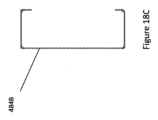
再び図12を参照すると、支持フレーム400は、屋根支持体を形成する複数の溝形梁406を含む。屋根支持体を形成するよう構成される例示的な溝形梁406は、図18A、図18B及び図18Cに示される。特に、溝形梁406は、第一の端部480、第二の端部482及び第一の端部480から第二の端部482に向かって幅が徐々に増えている、実質的に長方形の腹板484を有している。溝形梁403,404,405と同様に、図18B及び図18Cに具体的に示されるように、溝形梁406は実質的にC字形状の断面を有する。第一の端部480における断面は、第二の端部482における断面の幅484Bよりも狭い幅484Aを有する。特に、断面は、図6Bに示されるように約10cmの幅484Aを有する腹板から図18Cに示されるように約20cmの幅484Bを有する腹板へ増大する。
Referring again to FIG. 12,
屋根支持体を形成するよう構成される徐々に幅が狭くなる溝形梁、例えば溝形梁406等を有することは、顕著な利点を有する。具体的には、屋根パネルは、屋根の一方の側部を持ち上げる更なる構造を必要とせずに、溝形梁406に直接取り付けられてもよい。従って、建造物を組み立てる複雑さが著しく低減され得る。更に、建造物の多くのプレハブ式部品が低減され得、結果としてコスト効率がより高くなり得る。一方の側部が持ち上げられた屋根は、雨が建造物から流れ落ちることができる、屋根のより低い側部へ雨が誘導されるという利点を有する。
Having a tapered channel beam configured to form a roof support, such as
図19を参照すると、2つの建築モジュールを有する建造物を形成する第二の支持フレーム400Bに接続される第一の支持フレーム400Aの等角図が示される。当業者は、建造物を構成するために使用され得る建築モジュールの数は任意であることを理解するだろう。幅、長さ及び高さといった建築モジュールの寸法は異なっていてもよい。例えば、2階建て建造物を目的として、建築モジュールの少なくとも1つは、6cmといった2倍の長さの鋼製支柱を有する支持フレームを有してもよい。追加の鋼製梁は、鋼製支柱の高さの約半分の長さで水平に延び、それによって2階の床用の支持体を形成してもよい。
Referring to FIG. 19, an isometric view of a
2つの隣接する支持フレーム400A,400Bは、第一の支持フレーム400Aの鋼製支柱402Aと、隣接する第二の支持フレーム400Bの鋼製支柱402Bとを接続することによって互いに接続される。例えば、各鋼製支柱402A,402Bは、溝形梁であってもよく、鋼製支柱402A,402Bは、各々のC字形溝がお互いに反対方向を向くよう配置される。言い換えると、鋼製支柱402A,402Bの長方形腹板は、互いに当接し、機械的留め具を使用して互いに接続され得る。
Two adjacent support frames 400A, 400B are connected to each other by connecting the steel struts 402A of the
この特定の例において、タイロッド(不図示)は、結果として得られる境界壁の一部である上部溝形梁と下部溝形梁の間にのみ設けられる。この理由は、通常内壁パネル内にタイロッドを設ける必要がないからである。内壁を形成するプレハブ式壁パネルは、支持フレーム400A,400Bに直接取り付けられてもよい。 In this particular example, tie rods (not shown) are provided only between the upper and lower channel beams that are part of the resulting boundary wall. This is because there is usually no need to provide tie rods in the interior wall panels. The prefabricated wall panels forming the inner walls may be attached directly to the support frames 400A, 400B.
第一及び第二の支持フレーム400A,400Bは、複数のフーチング500によって支持される。この特定の例において、第一及び第二の支持フレーム400A,400Bは、9つのフーチング500によって支持される。これは、両方の支持フレーム400A,400Bがフーチング500を共有する第一の支持フレーム400Aと第二の支持フレーム400Bの間で共有される境界に起因する。例示的なフーチング500の側面図は、図20に詳細に示される。各フーチング500は、ブロックの形態であってもよいコンクリート体502を含む。しかし、当業者は、他の形状も考えられることを理解するだろう。フーチング500は、高さが調節可能な支持要素504を更に含む。支持要素504は、支持フレーム400に直接取り付け可能な接続プレート506、及びコンクリート体502の螺子が切られたブッシュ510に挿入可能な螺子山付き足508を含む。従って、接続プレート506の高さは、螺子付きブッシュ510内で支持要素504を回転させることによって調整され得る。このように、建造物の支持フレームの水平化が簡素化され得る。この例において、フーチング500は、螺子山付き足508を適切な位置に係止する係止ナット512を更に含む。
The first and second support frames 400A, 400B are supported by a plurality of
図21を参照すると、図11に示される建造物300等の建造物を組み立てる方法600を説明するフローチャートが示される。この方法は、複数のフーチング500を地盤に配置する初期工程602を含んでもよい。更なる工程604において、支持フレームは、接続ブラケットを使用して複数の鋼製支柱と複数の鋼製梁を接続することによって組み立てられる。支持フレームが一度組み立てられると、支持フレームは、フーチングの接続プレートに取り付けられ得る(606)。しかし、当業者は、支持フレームを完全に組み立てる前に支持フレームの分離可能部の少なくとも一部をフーチングに取り付けてもよいことを理解するだろう。これは、建造物を水平化する作業を簡素化し得る。
Referring to FIG. 21, a flowchart illustrating a
更なる工程608において、複数のプレハブ式壁パネルは、支持フレームに対して配置され、ここで各プレハブ式壁パネルは、少なくとも1つの長手方向に延びる空洞を含む。その後、境界壁を形成する壁パネルの長手方向に延びる空洞を通ってタイロッドが延びるよう各タイロッドを2本の鋼製支柱に接続することによって、複数のタイロッドが配置される(610)。このように、プレハブ式壁パネルは、支持フレームに取り付けられてもよい。しかし、壁パネルを支持フレームに固定する代替的な又は追加の方法も考えられる。タイロッドは、上部溝形梁と下部溝形梁といった支持フレームの対抗する鋼製梁に固定されるよう位置付けられてもよい。タイロッドは、張力がかかるよう溝形梁に接続されてもよい。
In a
壁に内装又は外装を取り付ける工程、電気配管系統を設置する工程、並びに屋根パネル及び床パネルを支持フレームに取り付ける工程といった他の組立工程が続いてもよい。前述のように1以上の建築モジュールを含む建造物は、顕著な利点を有する。例えば、建造物の輸送容積が最小化され得る。従って、建造物の輸送及び組み立てが簡素化され、そうでなければ熟練した労働者及び専用の機械のために必要であろう費用が低減される。例えば、支持フレームの一部若しくは全ての部品は、又は建造物全体ですら、ボルト又は螺子棒といった機械的留め具又は機械系を使用して互いに接続され得る。このように、建設現場で溶接する必要が無くなるか又は少なくなる。 Other assembly steps may follow, such as attaching the interior or exterior to the walls, installing the electrical plumbing system, and attaching the roof and floor panels to the support frame. A building comprising one or more building modules as described above has significant advantages. For example, the transportation volume of the building can be minimized. Transport and assembly of the building is thus simplified, reducing costs that would otherwise be required for skilled labor and specialized machinery. For example, some or all parts of the support frame, or even the entire building, may be connected together using mechanical fasteners or systems such as bolts or threaded rods. In this way, the need for welding at the construction site is eliminated or reduced.
建造物のプレハブ式部品の輸送に関し、建造物の分離可能部は、積層可能に構成される。このように、輸送容積を最小化することができる。例えば、建造物の部品は、パレット上に配置され又は配置されなくてもよい複数のパックに梱包されてもよい。第一のパックは、例えば、支持フレームを形成する分離可能部を含んでもよい。第二のパックは、複数のプレハブ式壁パネルを含んでもよい。第三のパックは、内装及び外装を含んでもよい。第四のパックは、電気及び/又は配管系統用の部品を含んでもよい。第五のパックは、屋根パネルを含んでもよく、第六のパックは、床パネルを含んでもよい。複数のパックは、建造物をどのように組み立てるべきかを規定する順番に番号付けられてもよい。このように、建設現場の作業者は、プレハブ式建物を組み立てるためにどのパックを開けるべきかを容易に識別することができる。 For transportation of prefabricated parts of the building, the separable parts of the building are configured to be stackable. In this way the transport volume can be minimized. For example, building parts may be packaged in multiple packs that may or may not be placed on pallets. The first pack may for example comprise a separable part forming a support frame. A second pack may include a plurality of prefabricated wall panels. A third pack may include an interior and an exterior. A fourth pack may contain components for electrical and/or plumbing systems. A fifth pack may include roof panels and a sixth pack may include floor panels. Multiple packs may be numbered in an order that defines how the building is to be assembled. In this way, construction site workers can easily identify which packs to open to assemble the prefabricated building.
支持フレームを形成する分離可能部に関し、鋼製梁は、輸送パックの容積を減らすことができるよう、互いの中に配置されるよう構成されてもよい。例えば、鋼製梁が前述のように溝形梁である場合、溝形梁は、より広い幅を有する別の溝形梁の溝内に位置させてもよい。同様に、2本の溝形梁は、各々の溝が互いに向き合うよう溝形梁を位置させることによって互いに噛み合わされてもよい。このように、より高い密度荷重で、よりコンパクトな輸送パックを達成することができる。 With respect to the separable parts forming the support frame, the steel beams may be arranged to be arranged within each other so as to reduce the volume of the transport pack. For example, if the steel beam is a channel beam as described above, the channel beam may be positioned within the channel of another channel beam having a wider width. Similarly, two channel beams may be interdigitated by positioning the channel beams so that their respective channels face each other. In this way, more compact transport packs can be achieved with higher density loads.
具体的な一実施形態において、建造物の全ての部品は、フラットパックに梱包され、フラットパックの大きさは、各パックにおける最も大きい部品の底面積によって規定されてもよい。各フラットパックは、北大西洋貿易機関(NATO)におけるフラットパック基準を満たしてもよい。輸送パックは、プレハブ式建物の分離可能部の角及び縁を保護するよう配置される材料を更に含んでもよい。これにより、輸送パックを建設現場に移動させる際の物流上の損傷を低減し得るか、又は防ぐ可能性すらある。 In one specific embodiment, all parts of the building may be packaged in flat packs, the size of the flat pack being defined by the bottom area of the largest part in each pack. Each flat pack may meet flat pack standards at the North Atlantic Trade Organization (NATO). The transport pack may further comprise material arranged to protect the corners and edges of the separable parts of the prefabricated building. This may reduce or even prevent logistical damage when moving the transport pack to the construction site.
広義に説明される本発明の趣旨又は範囲を逸脱しない範囲で、具体的な実施形態及び/又は態様に示される発明に様々な変更及び/又は変形を加えてもよいことは、当業者によって理解されるだろう。例えば、本発明のある特徴が組み合わされることで更なる実施形態を形成できることは明らかであろう。従って、本実施形態及び本態様は、あらゆる点において例示的であり且つ限定的ではないと考えられるべきである。幾つかの実施形態は、図面を参照して説明されている。これらの図面は、本発明のシステム及び方法及びプログラムを実施する具体的な実施形態の特定の詳細を説明している。しかし、図面を用いて本発明を説明することは、図面に示される特徴に関連するいかなる限定も本発明に課すものではないと解釈されるべきである。 It will be appreciated by those skilled in the art that various modifications and/or variations may be made to the inventions shown in the specific embodiments and/or aspects without departing from the spirit or scope of the invention as broadly described. will be For example, it will be apparent that certain features of the invention can be combined to form further embodiments. Accordingly, the present embodiments and aspects are to be considered in all respects illustrative and not restrictive. Some embodiments have been described with reference to the drawings. These drawings set forth specific details of specific embodiments that implement the systems and methods and programs of the present invention. However, describing the invention using the drawings should not be construed as imposing any limitations on the invention with respect to the features shown in the drawings.
100 フーチング
102 杭構造
104 垂直建築柱
106 ベース構造
108 ベースプレート
110 アライメントバー
112 コンクリート層
113 腹板
114 コンクリート層内の開口
115 (アライメントバー用)コネクタ
116 中柱
118 中心開口
120,122 シャフト部品
124 シャフトビット
126 ヘリカルプレート
128 柱プレート
130 柱補強筋
132 柱プレート上の突出部
134 (スラブ補強筋用)コネクタ
136 スラブ補強筋
137 補強メッシュ
138 鋼管
140 吊り上げ要素
200 方法
300 プレハブ式建造物
302 プレハブ式壁パネル
304 プレハブ式屋根パネル
306 窓
308 ドア
310 フェンス付きテラス
312 階段
320 コア
322,324 外層
326 タイロッド
328 空洞
330 空間(突き合わせ面)
400 支持フレーム
402 鋼製支柱
403 溝形梁(幅10cm)
404 溝形梁(幅15cm)
405 溝形梁(幅20cm)
406 (屋根支持体を形成する)溝形梁
408 長方形腹板
410 第一のフランジ
412 第二のフランジ
414 (腹板の)内面
416 (腹板の)外面
418 (腹板の)第一の端
420 (腹板の)第二の端
422 (腹板の)第一の側部
424 (腹板の)第二の側部
426 (第一のフランジの)内側部
428 (第一のフランジの)外側部
430 (第二のフランジの)内側部
432 (第二のフランジの)外側部
434 第一のリップ
436 第二のリップ
438 (鋼製支柱の)第一の端
440 (鋼製支柱の)第二の端
442 第一の接続ブラケット
444 (第一の接続ブラケットの)ベースプレート
446 (ベースプレートの)一対の開口
448 第一の接続ブラケットの第一のブラケットフランジ
450 第一の接続ブラケットの第二のブラケットフランジ
452 第一の接続ブラケットの第三のブラケットフランジ
454 (第三のブラケットフランジの)一対の開口
456 第二の接続ブラケット
458 第二の接続ブラケットのベース
460 ベースの一対の開口
462 (第二の接続ブラケットの)第一のブラケットフランジ
464 (第二の接続ブラケットの)第二のブラケットフランジ
466 (第二の接続ブラケットの)第三のブラケットフランジ
468 第三の接続ブラケット
470 (第三の接続ブラケットの)第一のブラケットフランジ
472 (第三の接続ブラケットの)第二のブラケットフランジ
474,476 開口
478 ブラケット凹部
480 (屋根支持体の)第一の端
482 (屋根支持体の)第一の端
484 腹板
500 フーチング
502 コンクリート体
504 支持要素
506 接続プレート
508 螺子付き足
510 螺子付きブッシュ
512 係止ナット
600 方法
100
400
404 channel beam (width 15cm)
405 channel beam (width 20cm)
406 channel beam (forming roof support) 408 rectangular web 410 first flange 412 second flange 414 inner surface (of web) 416 outer surface (of web) 418 first end (of web) 420 second end (of web) 422 first side (of web) 424 second side (of web) 426 medial side (of first flange) 428 (of first flange) Outer part 430 Inner part (of second flange) 432 Outer part (of second flange) 434 First lip 436 Second lip 438 First end (of steel strut) 440 (of steel strut) second end 442 first connecting bracket 444 base plate (of first connecting bracket) 446 pair of openings (of base plate) 448 first bracket flange of first connecting bracket 450 second end of first connecting bracket Bracket flange 452 Third bracket flange of first connection bracket 454 Pair of openings (of third bracket flange) 456 Second connection bracket 458 Base of second connection bracket 460 Pair of openings of base 462 (second first bracket flange 464 (of second connection bracket) second bracket flange 466 (of second connection bracket) third bracket flange 468 third connection bracket 470 (of third connection bracket) first bracket flange 472 (of third connecting bracket) second bracket flange 474, 476 opening 478 bracket recess 480 first end (of roof support) 482 first (of roof support) End 484 Web 500 Footing 502 Concrete Body 504 Support Element 506 Connection Plate 508 Threaded Foot 510 Threaded Bushing 512 Lock Nut 600 Method
Claims (17)
ベースプレート及び前記ベースプレートの第1の面から突出する複数のアライメントバーを含むベース構造とを備え、
前記複数のプレキャストコンクリート層が積み重ねられる際、前記ベース構造の前記複数のアライメントバーが各コンクリート層の各々の開口を通って延びるよう構成され、
前記第1の面の反対側の前記ベースプレートの第2の面を通してベース構造に固定をする杭構造を更に有し、
前記プレキャストコンクリート層のうちの1以上は、フーチングを更なるフーチングに接続するために、使用時にコンクリートスラブ内に延びるスラブ補強筋を備える、建造物用のフーチング。 a plurality of precast concrete layers, each precast concrete layer including a plurality of reinforcing bars and a plurality of openings;
a base structure including a base plate and a plurality of alignment bars projecting from a first surface of the base plate;
wherein the plurality of alignment bars of the base structure extend through respective openings in each concrete layer when the plurality of precast concrete layers are stacked ;
further comprising a stake structure anchoring to a base structure through a second side of said base plate opposite said first side;
A footing for a building, wherein one or more of said precast concrete layers comprises slab reinforcing bars extending into the concrete slab in use to connect the footing to a further footing.
複数のプレキャストコンクリート層を設ける工程を含み、
各コンクリート層は、
a)コンクリート層を補強するための複数の補強筋を設け、
b)前記複数の補強筋が表面上に配される際に持ち上げられるように複数のスペーサーチェアを前記複数の補強筋に接続し、
c)鋼管が、フーチングの組み立て時に前記ベース構造の各々の前記アライメントバーを受けるよう配置される複数の開口を、前記コンクリート層が打設される際に形成するように、複数の鋼管を補強筋に接続し、且つ
d)前記コンクリート層を形成する鋳型にコンクリートを流し込む
ことによって作製され、
一以上のプレキャストコンクリート層のために、フーチングを更なるフーチングに接続するように使用時にフーチングからコンクリートスラブ内に延びるスラブ補強筋を複数接続する工程を含む、建造物のフーチングの作製方法。 providing a base structure including a base plate, a plurality of alignment bars projecting from a first side of the base plate, and stake structures secured to the base structure through a second side of the base plate opposite the first side; including the step of providing a plurality of precast concrete layers;
Each concrete layer is
a) providing a plurality of reinforcing bars to reinforce the concrete layer;
b) connecting a plurality of spacer chairs to the plurality of reinforcing bars such that the plurality of reinforcing bars are lifted when placed on a surface;
c) a plurality of steel pipes with reinforcing bars such that, when the concrete layer is poured , the steel pipes form a plurality of openings positioned to receive the alignment bars of each of the base structures when the footing is assembled; and d) pouring concrete into a mold that forms said concrete layer,
A method of making a building footing comprising connecting a plurality of slab reinforcing bars extending from the footing into a concrete slab in use to connect the footing to a further footing for one or more precast concrete layers.
複数の補強筋及び複数の開口を含む複数のプレキャストコンクリート層を設ける工程と、
前記ベース構造の前記複数のアライメントバーが各プレキャストコンクリート層の各々の前記開口を通って延びるように、前記複数のプレキャストコンクリート層を互いに積み重ねて配する工程と、
一以上のプレキャストコンクリート層が更に複数のスラブ補強筋を含み、フーチングを更なるフーチングに接続するよう、スラブ補強筋が、使用時にフーチングからコンクリートスラブに延びるように、前記スラブ補強筋を有する一以上のプレキャストコンクリートスラブを配置する工程を有する建造物用のフーチングを組み立てる方法。 placing the base structure in the ground comprising a base plate , a plurality of alignment bars projecting from a first side of the base plate, and a stake structure secured to the base structure through a second side of the base plate opposite the first side. positioning;
providing a plurality of precast concrete layers including a plurality of reinforcing bars and a plurality of openings;
placing the plurality of precast concrete layers on top of each other such that the plurality of alignment bars of the base structure extend through the respective openings in each precast concrete layer;
One or more of the precast concrete layers further comprising a plurality of slab reinforcing bars and having said slab reinforcing bars such that the slab reinforcing bars extend from the footing to the concrete slab in use to connect the footing to the further footing. A method of assembling a footing for a building comprising placing a precast concrete slab of .
杭構造を前記フーチングの前記ベースプレートに固定する工程と、
建造物が建てられる地盤内に前記杭構造及び前記ベースプレートを配する工程と、
前記ベース構造の前記複数のアライメントバーが各コンクリート層の各々の開口を通って延びるように前記複数のプレキャストコンクリート層を互いに積み重ねて配する工程と、
前記建造物の垂直柱を前記フーチングに固定する工程と、
各フーチングの1以上の前記プレキャストコンクリート層が、コンクリートスラブ内に延びる複数のスラブ補強筋を含み、それによって複数のフーチングが接続される、複数のフーチング間にコンクリートスラブを設ける工程とを有する建造物の基礎を形成する方法。
providing a footing comprising each precast concrete layer comprising a plurality of reinforcing bars and a plurality of openings and further comprising a base structure comprising a base plate and a plurality of alignment bars projecting from the base plate;
securing a pile structure to the base plate of the footing;
placing the pile structure and the base plate in the ground on which the building is to be erected;
placing the plurality of precast concrete layers on top of each other such that the plurality of alignment bars of the base structure extend through respective openings in each concrete layer;
securing a vertical column of the building to the footing;
providing a concrete slab between a plurality of footings, wherein one or more of said precast concrete layers of each footing includes a plurality of slab reinforcing bars extending into the concrete slab whereby the plurality of footings are connected. how to form the basis of
Applications Claiming Priority (5)
| Application Number | Priority Date | Filing Date | Title |
|---|---|---|---|
| AU2017905037 | 2017-12-16 | ||
| AU2017905037A AU2017905037A0 (en) | 2017-12-16 | A footing for a building structure | |
| AU2017905038A AU2017905038A0 (en) | 2017-12-17 | A prefabricated building structure | |
| AU2017905038 | 2017-12-17 | ||
| PCT/AU2018/051343 WO2019113651A1 (en) | 2017-12-16 | 2018-12-14 | A building system |
Publications (2)
| Publication Number | Publication Date |
|---|---|
| JP2021507148A JP2021507148A (en) | 2021-02-22 |
| JP7325835B2 true JP7325835B2 (en) | 2023-08-15 |
Family
ID=66818777
Family Applications (1)
| Application Number | Title | Priority Date | Filing Date |
|---|---|---|---|
| JP2020533102A Active JP7325835B2 (en) | 2017-12-16 | 2018-12-14 | building system |
Country Status (7)
| Country | Link |
|---|---|
| US (1) | US11598066B2 (en) |
| EP (1) | EP3724406B1 (en) |
| JP (1) | JP7325835B2 (en) |
| CN (2) | CN111712601B (en) |
| AU (2) | AU2018384085A1 (en) |
| SG (1) | SG11202005453WA (en) |
| WO (1) | WO2019113651A1 (en) |
Families Citing this family (5)
| Publication number | Priority date | Publication date | Assignee | Title |
|---|---|---|---|---|
| US11078660B2 (en) * | 2018-08-13 | 2021-08-03 | Blach Construction Company | Prefabricated building system and methods |
| EP4053343A1 (en) * | 2021-03-01 | 2022-09-07 | BTE Stelcon GmbH | Mobile foundation |
| CN113338327A (en) * | 2021-06-15 | 2021-09-03 | 国网江西省电力有限公司电力科学研究院 | Split frame type prefabricated foundation for assembled ring net cages and construction method |
| AU2022328205B2 (en) | 2021-08-12 | 2024-04-11 | Plank Structural Systems LLC | Foam filled structural plank building foundation with laminated reinforcement |
| CN115387479B (en) * | 2022-08-25 | 2024-03-22 | 广州建筑产业研究院有限公司 | Method for installing multi-layer MIC modular building |
Citations (7)
| Publication number | Priority date | Publication date | Assignee | Title |
|---|---|---|---|---|
| JP2000352108A (en) | 1999-06-10 | 2000-12-19 | Kajima Corp | Precast block construction |
| JP2002047662A (en) | 2000-08-02 | 2002-02-15 | Oomi Kagaku Touki Kk | Portable columnar foundation body and its installation method |
| JP2005220688A (en) | 2004-02-09 | 2005-08-18 | Takenaka Komuten Co Ltd | Wall-type reinforced concrete structure and constructing method of of the same |
| JP2006104883A (en) | 2004-10-08 | 2006-04-20 | Prologis:Kk | Base-isolated building |
| JP2009293349A (en) | 2008-06-09 | 2009-12-17 | Ohbayashi Corp | Joint structure between pile and foundation, construction method thereof, and joint method of pile to foundation |
| JP2012087586A (en) | 2010-10-22 | 2012-05-10 | Lixil Corp | Foundation structure of column of car port or terrace or the like, construction method of foundation of column and precast concrete block |
| CN102733381A (en) | 2012-07-09 | 2012-10-17 | 卢治红 | Rotary type composite pile foundation, and preparation method of rotary type composite pile foundation |
Family Cites Families (30)
| Publication number | Priority date | Publication date | Assignee | Title |
|---|---|---|---|---|
| US3224151A (en) * | 1962-06-26 | 1965-12-21 | Inland Steel Products Company | Roof beams and supporting columns |
| NL8004538A (en) * | 1980-08-11 | 1982-03-01 | Siemen Spinder Handelende Onde | Concrete anchoring foot placement method - using stack of prefabricated slabs fitted over guide bars on metal baseplate |
| JPS6221744A (en) * | 1985-07-17 | 1987-01-30 | 鹿島建設株式会社 | Manufacture of precast composite structure of carbon fiber reinforced concrete |
| GB8614312D0 (en) | 1986-06-12 | 1986-07-16 | Structured Steel Systems Ltd | Assembling structures |
| AU620806B2 (en) * | 1987-05-20 | 1992-02-27 | Sypak Consolidated Industries Pty. Ltd. | A building structure and method of erecting structures |
| JPH02164933A (en) * | 1988-12-19 | 1990-06-25 | Asahi Chem Ind Co Ltd | Architecture foundation construction method |
| JPH0455522A (en) * | 1990-06-22 | 1992-02-24 | Sanwa Koki Kk | Foundation construction method for temporary column |
| JPH0457530U (en) * | 1990-09-19 | 1992-05-18 | ||
| US5884442A (en) * | 1997-03-28 | 1999-03-23 | Structural Systems Ltd. | Composite joist and concrete panel assembly |
| JP2000265574A (en) * | 1999-03-18 | 2000-09-26 | For You Planning Consultant:Kk | High floor type steel frame footing beam method |
| DE60035722D1 (en) * | 2000-12-08 | 2007-09-06 | Hajime Yauchi | SHEARING UNIT FOR PRODUCING CONCRETE BUILDINGS, METHOD FOR CONSTRUCTING A CONCRETE CONSTRUCTION, AND CONCRETE CONSTRUCTION PRODUCED BY USE OF THE CONCRETE BUILDING SHACKING |
| US7185467B2 (en) * | 2003-10-06 | 2007-03-06 | Oscar Marty | Modular system of permanent forms for casting reinforced concrete buildings on site |
| US8033757B2 (en) * | 2006-09-08 | 2011-10-11 | Ben Stroyer | Auger grouted displacement pile |
| CN101255700B (en) * | 2008-01-22 | 2013-01-30 | 赵正义 | Vertical combined novel foundation of mast mechanical equipment |
| US9957686B2 (en) * | 2009-09-16 | 2018-05-01 | Pre-Con Products, Ltd. | Modular foundation system and method |
| AU2010224302A1 (en) * | 2009-09-17 | 2011-03-31 | Centrix Holdings Pty Ltd | Building Frame Stud Bracket |
| AU2010226975A1 (en) * | 2009-10-06 | 2011-04-21 | Griffiths Civil Build Limited | Precast Concrete Foundation Block and Foundation |
| KR20120003814A (en) | 2010-07-05 | 2012-01-11 | 에프 아이 에이치 (홍콩) 리미티드 | Touch-type transparent keyboard |
| JP5814003B2 (en) * | 2011-06-13 | 2015-11-17 | 積水ハウス株式会社 | Connecting bracket, frame provided with the same, and building using the same |
| US9181674B2 (en) * | 2011-06-27 | 2015-11-10 | Hubbell Incorporated | Seismic restraint helical pile systems and method and apparatus for forming same |
| KR101165972B1 (en) * | 2012-01-12 | 2012-07-18 | (주)홍지디씨에스 | The upright structure by docking of a file and a superstructure |
| MY184136A (en) * | 2013-08-21 | 2021-03-22 | Chin Chai Ong | End plate for concrete piles |
| US9410316B2 (en) * | 2013-12-24 | 2016-08-09 | Reigstad & Associates, Inc. | Post-tension concrete leave out splicing system and method |
| CN104164839B (en) * | 2014-07-31 | 2016-08-17 | 天津市市政工程设计研究院 | A kind of construction method widening box culvert |
| JP6585390B2 (en) * | 2015-06-11 | 2019-10-02 | 旭コンクリート工業株式会社 | Basic block |
| CN204703184U (en) * | 2015-06-11 | 2015-10-14 | 北京东方昊炅科技发展有限公司 | A kind of foundation structure being convenient to grafting |
| CN204940318U (en) * | 2015-08-10 | 2016-01-06 | 成都深蓝高新技术发展有限公司 | Screw pile spin pile pile foundation |
| CA2914598C (en) * | 2015-12-08 | 2017-10-24 | 351471 Alberta Ltd. | Helical pile coupler, assembly, and method |
| CN105862900B (en) * | 2016-05-25 | 2018-08-28 | 山东大学 | Prefabricated garage structural system based on prefabricated pile and method |
| CN106894437A (en) * | 2017-02-15 | 2017-06-27 | 同济大学建筑设计研究院(集团)有限公司 | Limited prestressing precast concrete foundation, communication tower building and construction method |
-
2018
- 2018-12-14 AU AU2018384085A patent/AU2018384085A1/en active Pending
- 2018-12-14 EP EP18888311.0A patent/EP3724406B1/en active Active
- 2018-12-14 US US16/954,442 patent/US11598066B2/en active Active
- 2018-12-14 CN CN201880089444.3A patent/CN111712601B/en active Active
- 2018-12-14 SG SG11202005453WA patent/SG11202005453WA/en unknown
- 2018-12-14 JP JP2020533102A patent/JP7325835B2/en active Active
- 2018-12-14 WO PCT/AU2018/051343 patent/WO2019113651A1/en active Application Filing
- 2018-12-14 CN CN202211698128.0A patent/CN116201159A/en active Pending
-
2021
- 2021-10-06 AU AU2021107573A patent/AU2021107573A4/en active Active
Patent Citations (7)
| Publication number | Priority date | Publication date | Assignee | Title |
|---|---|---|---|---|
| JP2000352108A (en) | 1999-06-10 | 2000-12-19 | Kajima Corp | Precast block construction |
| JP2002047662A (en) | 2000-08-02 | 2002-02-15 | Oomi Kagaku Touki Kk | Portable columnar foundation body and its installation method |
| JP2005220688A (en) | 2004-02-09 | 2005-08-18 | Takenaka Komuten Co Ltd | Wall-type reinforced concrete structure and constructing method of of the same |
| JP2006104883A (en) | 2004-10-08 | 2006-04-20 | Prologis:Kk | Base-isolated building |
| JP2009293349A (en) | 2008-06-09 | 2009-12-17 | Ohbayashi Corp | Joint structure between pile and foundation, construction method thereof, and joint method of pile to foundation |
| JP2012087586A (en) | 2010-10-22 | 2012-05-10 | Lixil Corp | Foundation structure of column of car port or terrace or the like, construction method of foundation of column and precast concrete block |
| CN102733381A (en) | 2012-07-09 | 2012-10-17 | 卢治红 | Rotary type composite pile foundation, and preparation method of rotary type composite pile foundation |
Also Published As
| Publication number | Publication date |
|---|---|
| AU2018384085A1 (en) | 2020-07-23 |
| JP2021507148A (en) | 2021-02-22 |
| SG11202005453WA (en) | 2020-07-29 |
| US20210087773A1 (en) | 2021-03-25 |
| CN116201159A (en) | 2023-06-02 |
| EP3724406A1 (en) | 2020-10-21 |
| US11598066B2 (en) | 2023-03-07 |
| EP3724406C0 (en) | 2024-02-07 |
| WO2019113651A1 (en) | 2019-06-20 |
| EP3724406B1 (en) | 2024-02-07 |
| AU2021107573A4 (en) | 2022-01-06 |
| CN111712601B (en) | 2023-01-31 |
| CN111712601A (en) | 2020-09-25 |
| EP3724406A4 (en) | 2021-08-25 |
Similar Documents
| Publication | Publication Date | Title |
|---|---|---|
| JP7325835B2 (en) | building system | |
| US9388561B2 (en) | Modular construction mold apparatus and method for constructing concrete buildings and structures | |
| US6668507B2 (en) | Hurricane resistant precast composite building system | |
| US8082718B2 (en) | Bookshelf building panel and method of construction | |
| US20100058687A1 (en) | Method of constructing a multi-storey building using prefabricated modular panels | |
| US20130055671A1 (en) | Prefabricated modular building units | |
| AU2012214539A1 (en) | Precast wall panels and method of erecting a high-rise building using the panels | |
| US5491948A (en) | Tilt-up concrete pad and method of forming and erecting the tilt-up concrete pad | |
| AU2022204051A1 (en) | Method for constructing a concrete floor in a multistorey building | |
| KR101658648B1 (en) | Beam-column joint and simultaneous construction method of upper and lower part of building using thereof | |
| US7219474B2 (en) | Load bearing building panel | |
| CN110616846A (en) | Assembled building block, assembled building block lock anchor wall building system and construction method thereof | |
| WO2011127522A1 (en) | A method of forming a structural element and a method of building a structure | |
| US20070261335A1 (en) | Precast construction method and apparatus for variable size elevated platform | |
| CN116547432A (en) | Building component, building structure formed by building component and construction method of building structure | |
| CN210316179U (en) | Assembled building block and assembled building block lock anchor wall building system | |
| CN103827410A (en) | Masonry building and method for constructing masonry building | |
| US20200157811A1 (en) | Prefabricated self-supporting module for making building structures, more particularly swimming pools | |
| US20090133343A1 (en) | Formed-In-Place Wall Structure and Associated Methods | |
| KR102452802B1 (en) | A construction method to use the seismic resistant precast concrete members | |
| WO2007128054A1 (en) | Improved modular wall construction | |
| CA2639339A1 (en) | Method of constructing a multi-storey building using prefabricated modular panels | |
| JP3086384B2 (en) | Foundation structure and foundation construction method | |
| JP6382767B2 (en) | Foundation for the outer periphery of steel building and its construction method | |
| AU2002234421B2 (en) | A load bearing building panel |
Legal Events
| Date | Code | Title | Description |
|---|---|---|---|
| A711 | Notification of change in applicant |
Free format text: JAPANESE INTERMEDIATE CODE: A711 Effective date: 20210504 |
|
| A521 | Request for written amendment filed |
Free format text: JAPANESE INTERMEDIATE CODE: A523 Effective date: 20210616 |
|
| A621 | Written request for application examination |
Free format text: JAPANESE INTERMEDIATE CODE: A621 Effective date: 20211210 |
|
| A977 | Report on retrieval |
Free format text: JAPANESE INTERMEDIATE CODE: A971007 Effective date: 20220921 |
|
| A131 | Notification of reasons for refusal |
Free format text: JAPANESE INTERMEDIATE CODE: A131 Effective date: 20221101 |
|
| A601 | Written request for extension of time |
Free format text: JAPANESE INTERMEDIATE CODE: A601 Effective date: 20230127 |
|
| A601 | Written request for extension of time |
Free format text: JAPANESE INTERMEDIATE CODE: A601 Effective date: 20230403 |
|
| A521 | Request for written amendment filed |
Free format text: JAPANESE INTERMEDIATE CODE: A523 Effective date: 20230501 |
|
| A131 | Notification of reasons for refusal |
Free format text: JAPANESE INTERMEDIATE CODE: A131 Effective date: 20230530 |
|
| A521 | Request for written amendment filed |
Free format text: JAPANESE INTERMEDIATE CODE: A523 Effective date: 20230621 |
|
| TRDD | Decision of grant or rejection written | ||
| A01 | Written decision to grant a patent or to grant a registration (utility model) |
Free format text: JAPANESE INTERMEDIATE CODE: A01 Effective date: 20230711 |
|
| A61 | First payment of annual fees (during grant procedure) |
Free format text: JAPANESE INTERMEDIATE CODE: A61 Effective date: 20230726 |
|
| R150 | Certificate of patent or registration of utility model |
Ref document number: 7325835 Country of ref document: JP Free format text: JAPANESE INTERMEDIATE CODE: R150 |