JP7322017B2 - Drug delivery system and method - Google Patents
Drug delivery system and method Download PDFInfo
- Publication number
- JP7322017B2 JP7322017B2 JP2020526546A JP2020526546A JP7322017B2 JP 7322017 B2 JP7322017 B2 JP 7322017B2 JP 2020526546 A JP2020526546 A JP 2020526546A JP 2020526546 A JP2020526546 A JP 2020526546A JP 7322017 B2 JP7322017 B2 JP 7322017B2
- Authority
- JP
- Japan
- Prior art keywords
- catheter
- fluid
- needle
- patient
- drug
- Prior art date
- Legal status (The legal status is an assumption and is not a legal conclusion. Google has not performed a legal analysis and makes no representation as to the accuracy of the status listed.)
- Active
Links
Images


Classifications
-
- A—HUMAN NECESSITIES
- A61—MEDICAL OR VETERINARY SCIENCE; HYGIENE
- A61M—DEVICES FOR INTRODUCING MEDIA INTO, OR ONTO, THE BODY; DEVICES FOR TRANSDUCING BODY MEDIA OR FOR TAKING MEDIA FROM THE BODY; DEVICES FOR PRODUCING OR ENDING SLEEP OR STUPOR
- A61M25/00—Catheters; Hollow probes
- A61M25/0021—Catheters; Hollow probes characterised by the form of the tubing
- A61M25/0023—Catheters; Hollow probes characterised by the form of the tubing by the form of the lumen, e.g. cross-section, variable diameter
- A61M25/0026—Multi-lumen catheters with stationary elements
- A61M25/003—Multi-lumen catheters with stationary elements characterized by features relating to least one lumen located at the distal part of the catheter, e.g. filters, plugs or valves
-
- A—HUMAN NECESSITIES
- A61—MEDICAL OR VETERINARY SCIENCE; HYGIENE
- A61M—DEVICES FOR INTRODUCING MEDIA INTO, OR ONTO, THE BODY; DEVICES FOR TRANSDUCING BODY MEDIA OR FOR TAKING MEDIA FROM THE BODY; DEVICES FOR PRODUCING OR ENDING SLEEP OR STUPOR
- A61M5/00—Devices for bringing media into the body in a subcutaneous, intra-vascular or intramuscular way; Accessories therefor, e.g. filling or cleaning devices, arm-rests
- A61M5/14—Infusion devices, e.g. infusing by gravity; Blood infusion; Accessories therefor
- A61M5/142—Pressure infusion, e.g. using pumps
- A61M5/145—Pressure infusion, e.g. using pumps using pressurised reservoirs, e.g. pressurised by means of pistons
- A61M5/1452—Pressure infusion, e.g. using pumps using pressurised reservoirs, e.g. pressurised by means of pistons pressurised by means of pistons
- A61M5/14546—Front-loading type injectors
-
- A—HUMAN NECESSITIES
- A61—MEDICAL OR VETERINARY SCIENCE; HYGIENE
- A61M—DEVICES FOR INTRODUCING MEDIA INTO, OR ONTO, THE BODY; DEVICES FOR TRANSDUCING BODY MEDIA OR FOR TAKING MEDIA FROM THE BODY; DEVICES FOR PRODUCING OR ENDING SLEEP OR STUPOR
- A61M25/00—Catheters; Hollow probes
- A61M25/0017—Catheters; Hollow probes specially adapted for long-term hygiene care, e.g. urethral or indwelling catheters to prevent infections
-
- A—HUMAN NECESSITIES
- A61—MEDICAL OR VETERINARY SCIENCE; HYGIENE
- A61M—DEVICES FOR INTRODUCING MEDIA INTO, OR ONTO, THE BODY; DEVICES FOR TRANSDUCING BODY MEDIA OR FOR TAKING MEDIA FROM THE BODY; DEVICES FOR PRODUCING OR ENDING SLEEP OR STUPOR
- A61M25/00—Catheters; Hollow probes
- A61M25/0021—Catheters; Hollow probes characterised by the form of the tubing
- A61M25/0023—Catheters; Hollow probes characterised by the form of the tubing by the form of the lumen, e.g. cross-section, variable diameter
- A61M25/0026—Multi-lumen catheters with stationary elements
- A61M25/0032—Multi-lumen catheters with stationary elements characterized by at least one unconventionally shaped lumen, e.g. polygons, ellipsoids, wedges or shapes comprising concave and convex parts
-
- A—HUMAN NECESSITIES
- A61—MEDICAL OR VETERINARY SCIENCE; HYGIENE
- A61M—DEVICES FOR INTRODUCING MEDIA INTO, OR ONTO, THE BODY; DEVICES FOR TRANSDUCING BODY MEDIA OR FOR TAKING MEDIA FROM THE BODY; DEVICES FOR PRODUCING OR ENDING SLEEP OR STUPOR
- A61M25/00—Catheters; Hollow probes
- A61M25/0043—Catheters; Hollow probes characterised by structural features
- A61M25/0045—Catheters; Hollow probes characterised by structural features multi-layered, e.g. coated
-
- A—HUMAN NECESSITIES
- A61—MEDICAL OR VETERINARY SCIENCE; HYGIENE
- A61M—DEVICES FOR INTRODUCING MEDIA INTO, OR ONTO, THE BODY; DEVICES FOR TRANSDUCING BODY MEDIA OR FOR TAKING MEDIA FROM THE BODY; DEVICES FOR PRODUCING OR ENDING SLEEP OR STUPOR
- A61M25/00—Catheters; Hollow probes
- A61M25/10—Balloon catheters
- A61M25/1002—Balloon catheters characterised by balloon shape
-
- A—HUMAN NECESSITIES
- A61—MEDICAL OR VETERINARY SCIENCE; HYGIENE
- A61M—DEVICES FOR INTRODUCING MEDIA INTO, OR ONTO, THE BODY; DEVICES FOR TRANSDUCING BODY MEDIA OR FOR TAKING MEDIA FROM THE BODY; DEVICES FOR PRODUCING OR ENDING SLEEP OR STUPOR
- A61M25/00—Catheters; Hollow probes
- A61M25/10—Balloon catheters
- A61M25/1011—Multiple balloon catheters
-
- A—HUMAN NECESSITIES
- A61—MEDICAL OR VETERINARY SCIENCE; HYGIENE
- A61M—DEVICES FOR INTRODUCING MEDIA INTO, OR ONTO, THE BODY; DEVICES FOR TRANSDUCING BODY MEDIA OR FOR TAKING MEDIA FROM THE BODY; DEVICES FOR PRODUCING OR ENDING SLEEP OR STUPOR
- A61M39/00—Tubes, tube connectors, tube couplings, valves, access sites or the like, specially adapted for medical use
- A61M39/02—Access sites
- A61M39/0208—Subcutaneous access sites for injecting or removing fluids
-
- A—HUMAN NECESSITIES
- A61—MEDICAL OR VETERINARY SCIENCE; HYGIENE
- A61M—DEVICES FOR INTRODUCING MEDIA INTO, OR ONTO, THE BODY; DEVICES FOR TRANSDUCING BODY MEDIA OR FOR TAKING MEDIA FROM THE BODY; DEVICES FOR PRODUCING OR ENDING SLEEP OR STUPOR
- A61M5/00—Devices for bringing media into the body in a subcutaneous, intra-vascular or intramuscular way; Accessories therefor, e.g. filling or cleaning devices, arm-rests
- A61M5/007—Devices for bringing media into the body in a subcutaneous, intra-vascular or intramuscular way; Accessories therefor, e.g. filling or cleaning devices, arm-rests for contrast media
-
- A—HUMAN NECESSITIES
- A61—MEDICAL OR VETERINARY SCIENCE; HYGIENE
- A61M—DEVICES FOR INTRODUCING MEDIA INTO, OR ONTO, THE BODY; DEVICES FOR TRANSDUCING BODY MEDIA OR FOR TAKING MEDIA FROM THE BODY; DEVICES FOR PRODUCING OR ENDING SLEEP OR STUPOR
- A61M5/00—Devices for bringing media into the body in a subcutaneous, intra-vascular or intramuscular way; Accessories therefor, e.g. filling or cleaning devices, arm-rests
- A61M5/14—Infusion devices, e.g. infusing by gravity; Blood infusion; Accessories therefor
- A61M5/1407—Infusion of two or more substances
- A61M5/1408—Infusion of two or more substances in parallel, e.g. manifolds, sequencing valves
-
- A—HUMAN NECESSITIES
- A61—MEDICAL OR VETERINARY SCIENCE; HYGIENE
- A61M—DEVICES FOR INTRODUCING MEDIA INTO, OR ONTO, THE BODY; DEVICES FOR TRANSDUCING BODY MEDIA OR FOR TAKING MEDIA FROM THE BODY; DEVICES FOR PRODUCING OR ENDING SLEEP OR STUPOR
- A61M5/00—Devices for bringing media into the body in a subcutaneous, intra-vascular or intramuscular way; Accessories therefor, e.g. filling or cleaning devices, arm-rests
- A61M5/14—Infusion devices, e.g. infusing by gravity; Blood infusion; Accessories therefor
- A61M5/168—Means for controlling media flow to the body or for metering media to the body, e.g. drip meters, counters ; Monitoring media flow to the body
- A61M5/172—Means for controlling media flow to the body or for metering media to the body, e.g. drip meters, counters ; Monitoring media flow to the body electrical or electronic
- A61M5/1723—Means for controlling media flow to the body or for metering media to the body, e.g. drip meters, counters ; Monitoring media flow to the body electrical or electronic using feedback of body parameters, e.g. blood-sugar, pressure
- A61M2005/1726—Means for controlling media flow to the body or for metering media to the body, e.g. drip meters, counters ; Monitoring media flow to the body electrical or electronic using feedback of body parameters, e.g. blood-sugar, pressure the body parameters being measured at, or proximate to, the infusion site
-
- A—HUMAN NECESSITIES
- A61—MEDICAL OR VETERINARY SCIENCE; HYGIENE
- A61M—DEVICES FOR INTRODUCING MEDIA INTO, OR ONTO, THE BODY; DEVICES FOR TRANSDUCING BODY MEDIA OR FOR TAKING MEDIA FROM THE BODY; DEVICES FOR PRODUCING OR ENDING SLEEP OR STUPOR
- A61M25/00—Catheters; Hollow probes
- A61M2025/0007—Epidural catheters
-
- A—HUMAN NECESSITIES
- A61—MEDICAL OR VETERINARY SCIENCE; HYGIENE
- A61M—DEVICES FOR INTRODUCING MEDIA INTO, OR ONTO, THE BODY; DEVICES FOR TRANSDUCING BODY MEDIA OR FOR TAKING MEDIA FROM THE BODY; DEVICES FOR PRODUCING OR ENDING SLEEP OR STUPOR
- A61M25/00—Catheters; Hollow probes
- A61M25/0021—Catheters; Hollow probes characterised by the form of the tubing
- A61M25/0023—Catheters; Hollow probes characterised by the form of the tubing by the form of the lumen, e.g. cross-section, variable diameter
- A61M2025/0024—Expandable catheters or sheaths
-
- A—HUMAN NECESSITIES
- A61—MEDICAL OR VETERINARY SCIENCE; HYGIENE
- A61M—DEVICES FOR INTRODUCING MEDIA INTO, OR ONTO, THE BODY; DEVICES FOR TRANSDUCING BODY MEDIA OR FOR TAKING MEDIA FROM THE BODY; DEVICES FOR PRODUCING OR ENDING SLEEP OR STUPOR
- A61M25/00—Catheters; Hollow probes
- A61M25/10—Balloon catheters
- A61M2025/1043—Balloon catheters with special features or adapted for special applications
- A61M2025/1052—Balloon catheters with special features or adapted for special applications for temporarily occluding a vessel for isolating a sector
-
- A—HUMAN NECESSITIES
- A61—MEDICAL OR VETERINARY SCIENCE; HYGIENE
- A61M—DEVICES FOR INTRODUCING MEDIA INTO, OR ONTO, THE BODY; DEVICES FOR TRANSDUCING BODY MEDIA OR FOR TAKING MEDIA FROM THE BODY; DEVICES FOR PRODUCING OR ENDING SLEEP OR STUPOR
- A61M2205/00—General characteristics of the apparatus
- A61M2205/02—General characteristics of the apparatus characterised by a particular materials
- A61M2205/0266—Shape memory materials
-
- A—HUMAN NECESSITIES
- A61—MEDICAL OR VETERINARY SCIENCE; HYGIENE
- A61M—DEVICES FOR INTRODUCING MEDIA INTO, OR ONTO, THE BODY; DEVICES FOR TRANSDUCING BODY MEDIA OR FOR TAKING MEDIA FROM THE BODY; DEVICES FOR PRODUCING OR ENDING SLEEP OR STUPOR
- A61M2205/00—General characteristics of the apparatus
- A61M2205/33—Controlling, regulating or measuring
- A61M2205/3303—Using a biosensor
-
- A—HUMAN NECESSITIES
- A61—MEDICAL OR VETERINARY SCIENCE; HYGIENE
- A61M—DEVICES FOR INTRODUCING MEDIA INTO, OR ONTO, THE BODY; DEVICES FOR TRANSDUCING BODY MEDIA OR FOR TAKING MEDIA FROM THE BODY; DEVICES FOR PRODUCING OR ENDING SLEEP OR STUPOR
- A61M2205/00—General characteristics of the apparatus
- A61M2205/33—Controlling, regulating or measuring
- A61M2205/3331—Pressure; Flow
-
- A—HUMAN NECESSITIES
- A61—MEDICAL OR VETERINARY SCIENCE; HYGIENE
- A61M—DEVICES FOR INTRODUCING MEDIA INTO, OR ONTO, THE BODY; DEVICES FOR TRANSDUCING BODY MEDIA OR FOR TAKING MEDIA FROM THE BODY; DEVICES FOR PRODUCING OR ENDING SLEEP OR STUPOR
- A61M2205/00—General characteristics of the apparatus
- A61M2205/35—Communication
- A61M2205/3576—Communication with non implanted data transmission devices, e.g. using external transmitter or receiver
- A61M2205/3584—Communication with non implanted data transmission devices, e.g. using external transmitter or receiver using modem, internet or bluetooth
-
- A—HUMAN NECESSITIES
- A61—MEDICAL OR VETERINARY SCIENCE; HYGIENE
- A61M—DEVICES FOR INTRODUCING MEDIA INTO, OR ONTO, THE BODY; DEVICES FOR TRANSDUCING BODY MEDIA OR FOR TAKING MEDIA FROM THE BODY; DEVICES FOR PRODUCING OR ENDING SLEEP OR STUPOR
- A61M2205/00—General characteristics of the apparatus
- A61M2205/50—General characteristics of the apparatus with microprocessors or computers
- A61M2205/502—User interfaces, e.g. screens or keyboards
-
- A—HUMAN NECESSITIES
- A61—MEDICAL OR VETERINARY SCIENCE; HYGIENE
- A61M—DEVICES FOR INTRODUCING MEDIA INTO, OR ONTO, THE BODY; DEVICES FOR TRANSDUCING BODY MEDIA OR FOR TAKING MEDIA FROM THE BODY; DEVICES FOR PRODUCING OR ENDING SLEEP OR STUPOR
- A61M2205/00—General characteristics of the apparatus
- A61M2205/50—General characteristics of the apparatus with microprocessors or computers
- A61M2205/52—General characteristics of the apparatus with microprocessors or computers with memories providing a history of measured variating parameters of apparatus or patient
-
- A—HUMAN NECESSITIES
- A61—MEDICAL OR VETERINARY SCIENCE; HYGIENE
- A61M—DEVICES FOR INTRODUCING MEDIA INTO, OR ONTO, THE BODY; DEVICES FOR TRANSDUCING BODY MEDIA OR FOR TAKING MEDIA FROM THE BODY; DEVICES FOR PRODUCING OR ENDING SLEEP OR STUPOR
- A61M2210/00—Anatomical parts of the body
- A61M2210/06—Head
- A61M2210/0693—Brain, cerebrum
-
- A—HUMAN NECESSITIES
- A61—MEDICAL OR VETERINARY SCIENCE; HYGIENE
- A61M—DEVICES FOR INTRODUCING MEDIA INTO, OR ONTO, THE BODY; DEVICES FOR TRANSDUCING BODY MEDIA OR FOR TAKING MEDIA FROM THE BODY; DEVICES FOR PRODUCING OR ENDING SLEEP OR STUPOR
- A61M2210/00—Anatomical parts of the body
- A61M2210/10—Trunk
- A61M2210/1003—Spinal column
-
- A—HUMAN NECESSITIES
- A61—MEDICAL OR VETERINARY SCIENCE; HYGIENE
- A61M—DEVICES FOR INTRODUCING MEDIA INTO, OR ONTO, THE BODY; DEVICES FOR TRANSDUCING BODY MEDIA OR FOR TAKING MEDIA FROM THE BODY; DEVICES FOR PRODUCING OR ENDING SLEEP OR STUPOR
- A61M2230/00—Measuring parameters of the user
- A61M2230/04—Heartbeat characteristics, e.g. ECG, blood pressure modulation
- A61M2230/06—Heartbeat rate only
-
- A—HUMAN NECESSITIES
- A61—MEDICAL OR VETERINARY SCIENCE; HYGIENE
- A61M—DEVICES FOR INTRODUCING MEDIA INTO, OR ONTO, THE BODY; DEVICES FOR TRANSDUCING BODY MEDIA OR FOR TAKING MEDIA FROM THE BODY; DEVICES FOR PRODUCING OR ENDING SLEEP OR STUPOR
- A61M2230/00—Measuring parameters of the user
- A61M2230/40—Respiratory characteristics
- A61M2230/42—Rate
-
- A—HUMAN NECESSITIES
- A61—MEDICAL OR VETERINARY SCIENCE; HYGIENE
- A61M—DEVICES FOR INTRODUCING MEDIA INTO, OR ONTO, THE BODY; DEVICES FOR TRANSDUCING BODY MEDIA OR FOR TAKING MEDIA FROM THE BODY; DEVICES FOR PRODUCING OR ENDING SLEEP OR STUPOR
- A61M25/00—Catheters; Hollow probes
- A61M25/01—Introducing, guiding, advancing, emplacing or holding catheters
- A61M25/0105—Steering means as part of the catheter or advancing means; Markers for positioning
- A61M25/0133—Tip steering devices
- A61M25/0147—Tip steering devices with movable mechanical means, e.g. pull wires
-
- A—HUMAN NECESSITIES
- A61—MEDICAL OR VETERINARY SCIENCE; HYGIENE
- A61M—DEVICES FOR INTRODUCING MEDIA INTO, OR ONTO, THE BODY; DEVICES FOR TRANSDUCING BODY MEDIA OR FOR TAKING MEDIA FROM THE BODY; DEVICES FOR PRODUCING OR ENDING SLEEP OR STUPOR
- A61M25/00—Catheters; Hollow probes
- A61M25/01—Introducing, guiding, advancing, emplacing or holding catheters
- A61M25/09—Guide wires
-
- A—HUMAN NECESSITIES
- A61—MEDICAL OR VETERINARY SCIENCE; HYGIENE
- A61M—DEVICES FOR INTRODUCING MEDIA INTO, OR ONTO, THE BODY; DEVICES FOR TRANSDUCING BODY MEDIA OR FOR TAKING MEDIA FROM THE BODY; DEVICES FOR PRODUCING OR ENDING SLEEP OR STUPOR
- A61M5/00—Devices for bringing media into the body in a subcutaneous, intra-vascular or intramuscular way; Accessories therefor, e.g. filling or cleaning devices, arm-rests
- A61M5/178—Syringes
- A61M5/19—Syringes having more than one chamber, e.g. including a manifold coupling two parallelly aligned syringes through separate channels to a common discharge assembly
-
- C—CHEMISTRY; METALLURGY
- C12—BIOCHEMISTRY; BEER; SPIRITS; WINE; VINEGAR; MICROBIOLOGY; ENZYMOLOGY; MUTATION OR GENETIC ENGINEERING
- C12N—MICROORGANISMS OR ENZYMES; COMPOSITIONS THEREOF; PROPAGATING, PRESERVING, OR MAINTAINING MICROORGANISMS; MUTATION OR GENETIC ENGINEERING; CULTURE MEDIA
- C12N15/00—Mutation or genetic engineering; DNA or RNA concerning genetic engineering, vectors, e.g. plasmids, or their isolation, preparation or purification; Use of hosts therefor
- C12N15/09—Recombinant DNA-technology
- C12N15/11—DNA or RNA fragments; Modified forms thereof; Non-coding nucleic acids having a biological activity
- C12N15/111—General methods applicable to biologically active non-coding nucleic acids
-
- C—CHEMISTRY; METALLURGY
- C12—BIOCHEMISTRY; BEER; SPIRITS; WINE; VINEGAR; MICROBIOLOGY; ENZYMOLOGY; MUTATION OR GENETIC ENGINEERING
- C12N—MICROORGANISMS OR ENZYMES; COMPOSITIONS THEREOF; PROPAGATING, PRESERVING, OR MAINTAINING MICROORGANISMS; MUTATION OR GENETIC ENGINEERING; CULTURE MEDIA
- C12N15/00—Mutation or genetic engineering; DNA or RNA concerning genetic engineering, vectors, e.g. plasmids, or their isolation, preparation or purification; Use of hosts therefor
- C12N15/09—Recombinant DNA-technology
- C12N15/11—DNA or RNA fragments; Modified forms thereof; Non-coding nucleic acids having a biological activity
- C12N15/113—Non-coding nucleic acids modulating the expression of genes, e.g. antisense oligonucleotides; Antisense DNA or RNA; Triplex- forming oligonucleotides; Catalytic nucleic acids, e.g. ribozymes; Nucleic acids used in co-suppression or gene silencing
-
- C—CHEMISTRY; METALLURGY
- C12—BIOCHEMISTRY; BEER; SPIRITS; WINE; VINEGAR; MICROBIOLOGY; ENZYMOLOGY; MUTATION OR GENETIC ENGINEERING
- C12N—MICROORGANISMS OR ENZYMES; COMPOSITIONS THEREOF; PROPAGATING, PRESERVING, OR MAINTAINING MICROORGANISMS; MUTATION OR GENETIC ENGINEERING; CULTURE MEDIA
- C12N2310/00—Structure or type of the nucleic acid
- C12N2310/10—Type of nucleic acid
- C12N2310/11—Antisense
-
- C—CHEMISTRY; METALLURGY
- C12—BIOCHEMISTRY; BEER; SPIRITS; WINE; VINEGAR; MICROBIOLOGY; ENZYMOLOGY; MUTATION OR GENETIC ENGINEERING
- C12N—MICROORGANISMS OR ENZYMES; COMPOSITIONS THEREOF; PROPAGATING, PRESERVING, OR MAINTAINING MICROORGANISMS; MUTATION OR GENETIC ENGINEERING; CULTURE MEDIA
- C12N2320/00—Applications; Uses
- C12N2320/30—Special therapeutic applications
- C12N2320/32—Special delivery means, e.g. tissue-specific
-
- C—CHEMISTRY; METALLURGY
- C12—BIOCHEMISTRY; BEER; SPIRITS; WINE; VINEGAR; MICROBIOLOGY; ENZYMOLOGY; MUTATION OR GENETIC ENGINEERING
- C12N—MICROORGANISMS OR ENZYMES; COMPOSITIONS THEREOF; PROPAGATING, PRESERVING, OR MAINTAINING MICROORGANISMS; MUTATION OR GENETIC ENGINEERING; CULTURE MEDIA
- C12N2320/00—Applications; Uses
- C12N2320/30—Special therapeutic applications
- C12N2320/35—Special therapeutic applications based on a specific dosage / administration regimen
Description
本出願は、2016年12月21日に出願された米国仮特許出願第62/437,168号に関し、その全体が参照により本明細書に組み込まれる。 This application is related to US Provisional Patent Application No. 62/437,168, filed December 21, 2016, which is hereby incorporated by reference in its entirety.
(例えば、対象の脳または脊椎の脳脊髄液(CSF)またはくも膜下空間への髄腔内送達を介して)対象に薬物を送達するためのシステムおよび方法が本明細書に開示される。 Disclosed herein are systems and methods for delivering drugs to a subject (eg, via intrathecal delivery to the cerebrospinal fluid (CSF) or subarachnoid space of the subject's brain or spine).
患者に薬物を送達することが望ましい可能性がある実例が多く存在する。本明細書で使用される場合、「薬物」という用語は、ホルモン、幹細胞、遺伝子治療、化学物質、化合物、小分子および大分子、染料、抗体、ウイルス、治療薬剤などを含む、ヒトまたは動物の対象に送達され得る任意の機能薬剤を指す。 There are many instances in which it may be desirable to deliver drugs to a patient. As used herein, the term "drug" refers to human or animal Refers to any functional agent that can be delivered to a subject.
薬物の送達は、全身的な様態で行うことができるか、または特定の位置もしくは特定の分布パターンを標的とすることができる。しかしながら、意図された送達標的がアクセス可能ではないか、または最小侵襲的な様態ではアクセス可能ではないという実例が多く存在するので、標的薬物送達は困難であり得る。 Drug delivery can be in a systemic manner or can be targeted to a particular location or a particular pattern of distribution. Targeted drug delivery can be difficult, however, as there are many instances where the intended delivery target is not accessible, or is not accessible in a minimally invasive manner.
患者の自然の生理機能もまた、薬物送達の課題を提示し得る。例えば、髄腔内送達を介して所望のまたは最適な薬物分布を達成することは、少なくとも部分的には、正味の流れがほとんどなく振動性および拍動性である傾向がある、患者内のCSFの自然な流れのために困難であり得る。髄腔内空間に大量の薬物を送達すること、および薬物を分布させるために自然拡散に頼ることを伴う従来の技術は、非効率的であり、患者にとって有害であり得る。 A patient's natural physiology can also present challenges for drug delivery. For example, achieving desired or optimal drug distribution via intrathecal delivery is at least partially dependent on the CSF within the patient, which tends to be oscillatory and pulsatile with little net flow. can be difficult due to the natural flow of Conventional techniques that involve delivering large amounts of drug to the intrathecal space and relying on spontaneous diffusion to distribute the drug can be inefficient and harmful to the patient.
改善された薬物送達システムおよび方法に対する継続的な必要性が存在する。 There is a continuing need for improved drug delivery systems and methods.
薬物送達システムおよび方法が本明細書に開示されている。いくつかの実施形態では、薬物送達システムは、患者の生理学的パラメータ(例えば、患者の自然脳脊髄液(CSF)拍動または患者の心拍数もしくは呼吸数)と調和させて薬物を患者に送達するように構成され得る。いくつかの実施形態では、薬物送達システムは、患者への薬物の送達を制御するために、注入と吸引の組み合わせを使用するように構成され得る。上記のシステムで使用するためのカテーテル、コントローラ、および他の構成要素も開示されており、かかるシステムを使用する様々な方法も同様である。 Drug delivery systems and methods are disclosed herein. In some embodiments, the drug delivery system delivers the drug to the patient in harmony with the patient's physiological parameters (e.g., the patient's natural cerebrospinal fluid (CSF) pulsation or the patient's heart or respiratory rate). can be configured as In some embodiments, the drug delivery system can be configured to use a combination of infusion and aspiration to control the delivery of drug to the patient. Catheters, controllers, and other components for use with the above systems are also disclosed, as are various methods of using such systems.
いくつかの実施形態では、薬物送達システムは、少なくとも1つの流体管腔を有するカテーテルと、カテーテルを通して流体を注入するように構成されたポンプと、患者の生理学的パラメータを測定するように構成されたセンサと、カテーテルを通る薬物の注入をセンサによって測定された生理学的パラメータと調和させるようにポンプを制御するコントローラとを含む。 In some embodiments, a drug delivery system includes a catheter having at least one fluid lumen, a pump configured to inject fluid through the catheter, and a physiological parameter of a patient. It includes a sensor and a controller that controls the pump to coordinate the infusion of drugs through the catheter with the physiological parameters measured by the sensor.
コントローラは、センサによって測定されるように、注入頻度を患者の自然な髄腔内拍動の周波数と同期させ得る。コントローラは、センサによって測定されるように、注入位相を患者の自然な髄腔内拍動の位相と同期させ得る。コントローラは、センサによって測定されるように、患者の自然な髄腔内拍動の正弦波近似を確立し得る。コントローラは、注入を正弦波近似の上昇波と同期させ得る。コントローラは、注入を正弦波近似の下降波と同期させ得る。センサは、髄腔内圧力を測定するように構成され得る。センサは、髄腔内圧力を測定するように構成された第1のセンサと、心拍数を測定するように構成された第2のセンサとを含み得る。コントローラは、注入が遂行されず、第1および第2のセンサの出力に基づいて、コントローラが心拍数と髄腔内圧力との間の相関関係を確立する学習モードと、第2のセンサの出力に基づいて、コントローラがカテーテルを通る薬物の注入を患者の髄腔内拍動と調和させる注入モードとで動作可能であり得る。このシステムは、カテーテルと流体連通する埋め込み型注入ポートと、注入ポートと嵌合するように構成された体外式注射器とを含み得る。カテーテルは、第1および第2の流体管腔を含み得る。コントローラは、センサによって測定された生理学的パラメータと調和させて、第1の流体管腔を通して流体を吸引することと、第2の流体管腔を通して流体を注入することとを交互に行うようにポンプを制御するように構成され得る。センサは、心拍数、髄腔内圧力、髄腔内拍動数、呼吸数、肺活量、胸部拡張、胸部収縮、胸腔内圧力、および腹腔内圧力のうちの少なくとも1つを測定するように構成され得る。 The controller may synchronize the injection frequency with the frequency of the patient's natural intrathecal beats, as measured by the sensor. The controller may synchronize the injection phase with the phase of the patient's natural intrathecal beat, as measured by the sensor. The controller may establish a sinusoidal approximation of the patient's natural intrathecal pulse as measured by the sensor. The controller may synchronize the injection with a rising wave of sine wave approximation. The controller may synchronize the injection with a falling wave of sine wave approximation. The sensor may be configured to measure intrathecal pressure. The sensors may include a first sensor configured to measure intrathecal pressure and a second sensor configured to measure heart rate. The controller operates in a learning mode in which no injections are performed and the controller establishes a correlation between heart rate and intrathecal pressure based on the outputs of the first and second sensors and the output of the second sensor. , the controller may be operable in an injection mode that coordinates the injection of drug through the catheter with the patient's intrathecal pulsation. The system may include an implantable injection port in fluid communication with the catheter and an external syringe configured to mate with the injection port. The catheter may include first and second fluid lumens. The controller causes the pump to alternately aspirate fluid through the first fluid lumen and infuse fluid through the second fluid lumen in concert with the physiological parameter measured by the sensor. may be configured to control the The sensor is configured to measure at least one of heart rate, intrathecal pressure, intrathecal beat rate, respiratory rate, vital capacity, chest expansion, chest contraction, intrathoracic pressure, and intraperitoneal pressure. obtain.
いくつかの実施形態では、患者に薬物を送達する方法は、患者の髄腔内空間にカテーテルを挿入することと、センサを使用して患者の生理学的パラメータを測定することと、コントローラを用いて、カテーテルを通る薬物の注入をセンサによって測定された生理学的パラメータと調和させるようにポンプを制御することとを含む。 In some embodiments, a method of delivering a drug to a patient comprises inserting a catheter into the intrathecal space of the patient; measuring a physiological parameter of the patient using a sensor; and controlling the pump to match the infusion of drugs through the catheter with the physiological parameters measured by the sensors.
この方法は、センサによって測定されるように、注入頻度を患者の自然な髄腔内拍動の周波数と同期させることを含み得る。この方法は、センサによって測定されるように、注入位相を患者の自然な髄腔内拍動の位相と同期させることを含み得る。この方法は、センサによって測定されるように、患者の自然な髄腔内拍動の正弦波近似を確立することと、注入を正弦波近似の上昇波と同期させることとを含み得る。この方法は、センサによって測定されるように、患者の自然な髄腔内拍動の正弦波近似を確立することと、注入を正弦波近似の下降波と同期させることとを含み得る。センサは、髄腔内圧力を測定するように構成され得る。センサは、髄腔内圧力を測定するように構成された第1のセンサと、心拍数を測定するように構成された第2のセンサとを含み得る。この方法は、注入が遂行されていないときに第1および第2のセンサの出力に基づいて、心拍数と髄腔内圧力との間の相関関係を確立することと、第2のセンサの出力に基づいて、カテーテルを通る薬物の注入を患者の髄腔内拍動と調和させることとを含み得る。カテーテルは、第1および第2の流体管腔を含み得、この方法は、センサによって測定された生理学的パラメータと調和させて、第1の流体管腔を通して流体を吸引することと、第2の流体管腔を通して流体を注入することとを交互に行うようにポンプを制御することを含み得る。センサは、心拍数、髄腔内圧力、髄腔内拍動数、呼吸数、肺活量、胸部拡張、胸部収縮、胸腔内圧力、および腹腔内圧力のうちの少なくとも1つを測定するように構成され得る。カテーテルが患者の脊髄に沿って延在し、カテーテルの少なくとも一部分が患者の脊椎の頸部領域に配設され、カテーテルの少なくとも一部分が患者の脊椎の腰部領域に配設されるように、カテーテルを挿入することができる。この方法は、カテーテルを通して複数の異なる薬物を送達することを含み得、薬物の各々はカテーテルのそれぞれの流体管腔を通して送達される。この方法は、コントローラを用いて、カテーテルを通して流体を吸引するようにポンプを制御することを含み得る。カテーテルは、カテーテルの長さに沿って頭尾方向に隔置された複数の出口ポートを含み得、この方法は、カテーテルの第1のポートを通して薬物を注入することと、カテーテルの第2のポートを通して流体を吸引することとを含み得、第2のポートは、第1のポートに対して頭側である。患者の脊椎の頸部領域に配設されたカテーテルのポートを通して薬物を注入して、注入された薬物を頭蓋腔に進ませることができる。この方法は、患者からある量のCSFを吸引することと、カテーテルの第1の近位ポートを通して薬物を注入しながら、カテーテルの第2の遠位ポートを通してCSFを吸引して、第1のポートと第2のポートとの間に薬物のボーラスを形成することと、ボーラスに近位の位置に以前に抽出されたCSFを注入してボーラスを遠位方向に促すこととを含み得る。患者から吸引されるCSFの量は、患者の総CSFの約10体積%であり得る。カテーテルは、患者の経皮的腰部穿刺を通して挿入され得る。注入は、薬物の第1の量を注入することと、薬物の第2の量を吸引することとを交互に行うことを含み得、第2の量は第1の量未満である。薬物を標的領域に送達することができ、標的領域は、患者の髄腔内空間、患者の軟膜下領域、患者の小脳、患者の歯状核、患者の後根神経節、および患者の運動神経細胞のうちの少なくとも1つである。薬物は、アンチセンスオリゴヌクレオチド、立体的に純粋な(stereopure)核酸、ウイルス、アデノ随伴ウイルス(AAV)、非ウイルス遺伝子治療、ベキソソーム(vexosome)、およびリポソームのうちの少なくとも1つを含み得る。この方法は、薬物を送達することによって遺伝子治療を遂行すること、薬物を送達することによって遺伝子編集を遂行すること、薬物を送達することによって遺伝子スイッチを遂行すること、および薬物を送達することによって非ウイルス遺伝子治療を遂行することのうちの少なくとも1つを含み得る。この方法は、患者の総CSF量を判定することと、総CSF量に基づいて注入を調整することとを含み得る。 The method may include synchronizing the injection frequency with the frequency of the patient's natural intrathecal beats, as measured by a sensor. The method may include synchronizing the injection phase with the phase of the patient's natural intrathecal beat, as measured by the sensor. The method may include establishing a sinusoidal approximation of the patient's natural intrathecal pulse, as measured by the sensor, and synchronizing the injection with the rising wave of the sinusoidal approximation. The method may include establishing a sinusoidal approximation of the patient's natural intrathecal heartbeat, as measured by the sensor, and synchronizing the injection with the descending wave of the sinusoidal approximation. The sensor may be configured to measure intrathecal pressure. The sensors may include a first sensor configured to measure intrathecal pressure and a second sensor configured to measure heart rate. The method comprises establishing a correlation between heart rate and intrathecal pressure based on the outputs of the first and second sensors when no infusion is being performed; coordinating the infusion of the drug through the catheter with the patient's intrathecal pulsation based on . The catheter can include first and second fluid lumens, and the method comprises aspirating fluid through the first fluid lumen and Controlling the pump to alternately inject fluid through the fluid lumen may be included. The sensor is configured to measure at least one of heart rate, intrathecal pressure, intrathecal beat rate, respiratory rate, vital capacity, chest expansion, chest contraction, intrathoracic pressure, and intraperitoneal pressure. obtain. The catheter is positioned such that the catheter extends along the patient's spinal cord, at least a portion of the catheter is disposed in the cervical region of the patient's spine, and at least a portion of the catheter is disposed in the lumbar region of the patient's spine. can be inserted. The method may include delivering multiple different drugs through the catheter, each of the drugs being delivered through a respective fluid lumen of the catheter. The method may include using the controller to control a pump to draw fluid through the catheter. The catheter may include a plurality of exit ports craniocaudally spaced along the length of the catheter, the method comprising infusing a drug through a first port of the catheter and a second port of the catheter. aspirating fluid through the second port cephalad to the first port. Drugs can be injected through a port in a catheter placed in the cervical region of the patient's spine to advance the injected drug into the cranial cavity. The method involves aspirating an amount of CSF from the patient and infusing a drug through a first proximal port of the catheter while aspirating the CSF through a second distal port of the catheter to reach the first port. and a second port; and injecting previously extracted CSF at a location proximal to the bolus to prompt the bolus distally. The amount of CSF aspirated from the patient may be about 10% by volume of the patient's total CSF. The catheter may be inserted through a percutaneous lumbar puncture in the patient. Injecting may include alternating between injecting a first amount of drug and inhaling a second amount of drug, the second amount being less than the first amount. The drug can be delivered to target areas, which include the patient's intrathecal space, the patient's subpial region, the patient's cerebellum, the patient's dentate nucleus, the patient's dorsal root ganglion, and the patient's motor nerves. at least one of the cells. The drug may comprise at least one of antisense oligonucleotides, stereopure nucleic acids, viruses, adeno-associated viruses (AAV), non-viral gene therapy, vexosomes, and liposomes. The method includes performing gene therapy by delivering a drug, performing gene editing by delivering a drug, performing gene switching by delivering a drug, and performing gene switching by delivering a drug. at least one of performing non-viral gene therapy. The method may include determining the patient's total CSF volume and adjusting the infusion based on the total CSF volume.
いくつかの実施形態では、患者に薬物を送達する方法は、患者の髄腔内空間にカテーテルを挿入することと、コントローラを用いて、カテーテルを通して薬物を注入するようにポンプを制御することと、コントローラを用いて、カテーテルを通して流体を吸引するようにポンプを制御することと、患者内の標的部位への薬物の送達を標的とするように当該注入および当該吸引を制御することとを含む。 In some embodiments, a method of delivering a drug to a patient includes inserting a catheter into the intrathecal space of the patient; controlling, with a controller, a pump to infuse the drug through the catheter; Using a controller, controlling a pump to aspirate fluid through the catheter, and controlling the infusion and the aspiration to target delivery of the drug to a target site within the patient.
注入は、薬物を標的部位に向かって促すために、患者の自然CSF拍動を無効にし得る。注入は、患者の自然CSF拍動と調和して、薬物を標的部位に向かって促すことができる。注入は、薬物のボーラスを送達することと、次いで、ボーラスの後ろの流体の拍動性送達を遂行してボーラスを標的部位に向かって促すこととを含み得る。流体は、薬物、緩衝剤溶液、およびカテーテルを通して患者から吸引されたCSFのうちの少なくとも1つを含み得る。カテーテルの少なくとも一部分を標的領域に配設することができる。注入および吸引のうちの少なくとも一方を患者の生理学的パラメータと調和させることができる。生理学的パラメータは、心拍数、髄腔内圧力、髄腔内拍動数、呼吸数、肺活量、胸部拡張、胸部収縮、胸腔内圧力、および腹腔内圧力のうちの少なくとも1つであり得る。カテーテルは、第1および第2の流体管腔を含み得、この方法は、第1の流体管腔を通して流体を吸引することと、第2の流体管腔を通して流体を注入することとを交互に行うようにポンプを制御することを含み得る。カテーテルが患者の脊髄に沿って延在し、カテーテルの少なくとも一部分が患者の脊椎の頸部領域に配設され、カテーテルの少なくとも一部分が患者の脊椎の腰部領域に配設されるように、カテーテルを挿入することができる。この方法は、患者からある量のCSFを吸引することと、カテーテルの第1の近位ポートを通して薬物を注入しながら、カテーテルの第2の遠位ポートを通してCSFを吸引して、第1のポートと第2のポートとの間に薬物のボーラスを形成することと、ボーラスの近位の位置に以前に抽出されたCSFを注入してボーラスを遠位方向に促すこととを含み得る。この方法は、薬物の第1の量を注入することと、薬物の第2の量を吸引することとを交互に行うことを含み得、第2の量は第1の量未満である。標的部位は、患者の髄腔内空間、患者の軟膜下領域、患者の小脳、患者の歯状核、患者の後根神経節、および患者の運動神経細胞のうちの少なくとも1つであり得る。薬物は、アンチセンスオリゴヌクレオチド、立体的に純粋な核酸、ウイルス、アデノ随伴ウイルス(AAV)、非ウイルス遺伝子治療、ベキソソーム、およびリポソームのうちの少なくとも1つを含み得る。この方法は、薬物を送達することによって遺伝子治療を遂行すること、薬物を送達することによって遺伝子編集を遂行すること、薬物を送達することによって遺伝子スイッチを遂行すること、および薬物を送達することによって非ウイルス遺伝子治療を遂行することのうちの少なくとも1つを含み得る。この方法は、患者の総CSF量を判定することと、総CSF量に基づいて注入および/または吸引を調整することとを含み得る。 Infusion may override the patient's natural CSF pulsation in order to drive the drug toward the target site. Infusion can be coordinated with the patient's natural CSF beats to drive the drug toward the target site. Infusion may involve delivering a bolus of drug and then performing pulsatile delivery of fluid behind the bolus to urge the bolus toward the target site. The fluid may include at least one of drugs, buffer solutions, and CSF aspirated from the patient through the catheter. At least a portion of the catheter can be disposed in the target area. At least one of the infusion and aspiration can be coordinated with the patient's physiological parameters. The physiological parameter can be at least one of heart rate, intrathecal pressure, intrathecal beat rate, respiratory rate, vital capacity, chest expansion, chest contraction, intrathoracic pressure, and intraperitoneal pressure. The catheter may include first and second fluid lumens, and the method alternates between aspirating fluid through the first fluid lumen and infusing fluid through the second fluid lumen. controlling the pump to do so. The catheter is positioned such that the catheter extends along the patient's spinal cord, at least a portion of the catheter is disposed in the cervical region of the patient's spine, and at least a portion of the catheter is disposed in the lumbar region of the patient's spine. can be inserted. The method involves aspirating an amount of CSF from the patient and infusing a drug through a first proximal port of the catheter while aspirating the CSF through a second distal port of the catheter to reach the first port. and a second port; and injecting previously extracted CSF at a location proximal to the bolus to prompt the bolus distally. The method may include alternating between infusing a first amount of medicament and inhaling a second amount of medicament, the second amount being less than the first amount. The target site can be at least one of the patient's intrathecal space, the patient's subpial region, the patient's cerebellum, the patient's dentate nucleus, the patient's dorsal root ganglion, and the patient's motor neurons. The drug may comprise at least one of antisense oligonucleotides, sterically pure nucleic acids, viruses, adeno-associated viruses (AAV), non-viral gene therapy, bexosomes, and liposomes. The method includes performing gene therapy by delivering a drug, performing gene editing by delivering a drug, performing gene switching by delivering a drug, and performing gene switching by delivering a drug. at least one of performing non-viral gene therapy. The method may include determining the patient's total CSF volume and adjusting infusion and/or aspiration based on the total CSF volume.
いくつかの実施形態では、薬物送達カテーテルは、第1の流体ポートまで延在する第1の流体管腔、第2の流体ポートまで延在する第2の流体管腔、およびガイドワイヤ管腔を有する先端と、ハブと、先端の第1の流体管腔と流体連通する第1の流体管腔を画定する第1の流体管、先端の第2の流体管腔と流体連通する第2の流体管腔を画定する第2の流体管、先端のガイドワイヤ管腔内に配設された遠位端を有するガイドワイヤ、および少なくとも1つの内部チャネルを画定するシースを有する本体とを含み、少なくとも1つの内部チャネルの中にはガイドワイヤと、第1および第2の流体管とが配設されており、シースは、ハブの遠位端から先端の近位端まで延在する。 In some embodiments, the drug delivery catheter has a first fluid lumen extending to a first fluid port, a second fluid lumen extending to a second fluid port, and a guidewire lumen. a tip having a hub; a first fluid tube defining a first fluid lumen in fluid communication with the first fluid lumen of the tip; a second fluid in fluid communication with the second fluid lumen of the tip; a body having a sheath defining at least one internal channel; A guidewire and first and second fluid tubes are disposed within the two internal channels, and the sheath extends from the distal end of the hub to the proximal end of the tip.
先端は、テーパ状遠位端を有し得る。第1および第2の流体ポートは、先端の中心長手方向軸からずれていてもよい。第1および第2の流体ポートのうちの少なくとも一方を、先端の中心長手方向軸に対して直角に、またはそれに対して斜角に向けることができる。第1および第2の流体管は、ハブを通って途切れることなく延在し得る。第1および第2の流体管は、近位延長管が選択的に連結され得るそれぞれのコネクタにおいてハブ内で終端し得る。ガイドワイヤは、ハブを通って途切れることなく延在し得る。第1および第2の流体管は、それらの近位端にそれぞれの流体コネクタを有し得る。第1および第2の流体管のうちの少なくとも一方は、溶融シリカから形成され得る。第1および第2の流体管のうちの少なくとも一方は、収縮配管でコーティングされ得る。シースは、ポリウレタンから形成され得る。シースは、内部に形成された、第1および第2の流体管のうちの少なくとも一方の流体ポートと流体連通する開口部を含み得る。第1および第2のポートのうちの少なくとも一方は、螺旋状内部を有し得る。第1および第2のポートのうちの少なくとも一方は、ポートの遠位端に向かってテーバー状をなす内部を有し得る。第1の流体ポートは、第2の流体ポートの近位であり得る。カテーテルは、カテーテル内に回転可能に装着されたオーガを含み得る。カテーテルは、カテーテル内に配設された圧電変換器を含み得る。 The tip can have a tapered distal end. The first and second fluid ports may be offset from the central longitudinal axis of the tip. At least one of the first and second fluid ports can be oriented perpendicular to or oblique to the central longitudinal axis of the tip. The first and second fluid tubes may extend continuously through the hub. The first and second fluid tubes may terminate within the hub at respective connectors to which a proximal extension tube may be selectively coupled. A guidewire may extend through the hub uninterruptedly. The first and second fluid tubes may have respective fluid connectors at their proximal ends. At least one of the first and second fluid conduits may be formed from fused silica. At least one of the first and second fluid tubes may be coated with shrink tubing. The sheath may be formed from polyurethane. The sheath may include an opening formed therein in fluid communication with a fluid port of at least one of the first and second fluid conduits. At least one of the first and second ports may have a helical interior. At least one of the first and second ports may have an interior that tapers toward the distal end of the port. The first fluid port can be proximal to the second fluid port. The catheter may include an auger rotatably mounted within the catheter. The catheter may include a piezoelectric transducer disposed within the catheter.
いくつかの実施形態では、経皮的針装置は、内部に少なくとも1つの管腔を画定する細長いシャフトと、細長いシャフトの遠位端に配設されたセンサと、細長いシャフトに装着された、センサの出力を表示するように構成されたディスプレイと、細長いシャフトの近位端に配設された、少なくとも1つの管腔と流体接続をするためのコネクタとを含む。 In some embodiments, a percutaneous needle device comprises an elongated shaft defining at least one lumen therein, a sensor disposed at a distal end of the elongated shaft, and a sensor attached to the elongated shaft. and a connector for fluid communication with at least one lumen disposed at the proximal end of the elongate shaft.
装置は、針の管腔と流体連通する流体リザーバおよび平らなドームを含み得、平らなドームの作動は、リザーバから針の管腔を通して流体をポンピングするのに有効である。 The device may include a fluid reservoir in fluid communication with the needle lumen and a flat dome, wherein actuation of the flat dome is effective to pump fluid from the reservoir through the needle lumen.
いくつかの実施形態では、カテーテルは、内部に形成された1つ以上の流体管腔を有する細長い本体と、カテーテルの壁に形成された螺旋状スリットによって画定される流体ポートとを含む。 In some embodiments, the catheter includes an elongated body having one or more fluid lumens formed therein and fluid ports defined by helical slits formed in the wall of the catheter.
カテーテルは、実質的に球形の球状部によって画定された非外傷性遠位先端を含み得る。カテーテルは、第2の遠位向き流体ポートを含み得る。螺旋状スリットは、カテーテルの縮径部分の側壁に形成され得る。カテーテルは、カテーテルの主本体とカテーテルの縮径部分との間にテーパ状移行部を含み得る。 The catheter may include an atraumatic distal tip defined by a substantially spherical bulb. The catheter may include a second distal fluid port. A helical slit may be formed in the side wall of the reduced diameter section of the catheter. The catheter may include a tapered transition between the main body of the catheter and the reduced diameter section of the catheter.
いくつかの実施形態では、患者固有の注入方法は、患者の総CSF量を判定することと、判定された患者の総CSF量に基づいて、患者からある量のCSFを吸引することと、患者の髄腔内空間に薬物を注入することとを含む。 In some embodiments, the patient-specific infusion method comprises: determining a patient's total CSF volume; aspirating a volume of CSF from the patient based on the determined patient's total CSF volume; and injecting a drug into the intrathecal space of the.
本方法は、薬物を注入した後に、患者の吸引されたCSFを注入して、髄腔内空間内の所望の方向に薬物を押し込むことを含み得る。総CSF量は、患者の中枢神経系の術前画像から判定され得る。吸引されたCSFの量は、患者の総CSF量の約1%~約20%の範囲にあり得る。CSFの量が吸引されている間に薬物が注入され得る。 The method may include infusing the patient's aspirated CSF after infusing the drug to force the drug in a desired direction within the intrathecal space. Total CSF volume can be determined from preoperative imaging of the patient's central nervous system. The amount of aspirated CSF can range from about 1% to about 20% of the patient's total CSF amount. Drugs may be infused while a volume of CSF is being aspirated.
薬物送達システムおよび方法が本明細書に開示されている。いくつかの実施形態では、薬物送達システムは、患者の生理学的パラメータ(例えば、患者の自然脳脊髄液(CSF)拍動または患者の心拍数もしくは呼吸数)と調和させて薬物を患者に送達するように構成され得る。いくつかの実施形態では、薬物送達システムは、患者への薬物の送達を制御するために、注入と吸引の組み合わせを使用するように構成され得る。上記のシステムで使用するためのカテーテル、コントローラ、および他の構成要素も開示されており、かかるシステムを使用する様々な方法も同様である。 Drug delivery systems and methods are disclosed herein. In some embodiments, the drug delivery system delivers the drug to the patient in harmony with the patient's physiological parameters (e.g., the patient's natural cerebrospinal fluid (CSF) pulsation or the patient's heart or respiratory rate). can be configured as In some embodiments, the drug delivery system can be configured to use a combination of infusion and aspiration to control the delivery of drug to the patient. Catheters, controllers, and other components for use with the above systems are also disclosed, as are various methods of using such systems.
本明細書に開示される方法、システム、および装置の構造、機能、製造、および使用の原理の全体的な理解を提供するために、ある特定の例示的な実施形態をこれから説明する。これらの実施形態のうちの1つ以上の例が添付の図面に図示されている。当業者であれば、本明細書で具体的に記載され、添付の図面に図示される方法、システム、および装置は非限定的な例示的な実施形態であることを理解するであろう。1つの例示的な実施形態に関連して図示または記載されている特徴部を他の実施形態の特徴部と組み合わせることができる。かかる修正例および変形例は、本開示の範囲内に含まれることが意図されている。 Certain illustrative embodiments will now be described to provide an overall understanding of the principles of construction, function, manufacture, and use of the methods, systems, and apparatuses disclosed herein. One or more examples of these embodiments are illustrated in the accompanying drawings. Those skilled in the art will appreciate that the methods, systems, and apparatus specifically described herein and illustrated in the accompanying drawings are non-limiting exemplary embodiments. Features shown or described in connection with one exemplary embodiment may be combined with features of other embodiments. Such modifications and variations are intended to be included within the scope of this disclosure.
いくつかの実施形態では、自然CSF流と調和させて薬物を患者の中枢神経系に注射するか、または別の方法で送達するシステムおよび方法が提供されている。例えば、薬物を、自然CSFパルスと位相および/または周波数が同期した複数の段階で注射することができる。本明細書のシステムおよび方法は、従来の技術の場合よりも効率的に患者に薬物を送達することを可能にし得る。例えば、より少量の薬物を送達してもなお標的の目的地に到達することができ、それによって、コストおよび/または大量の薬物を送達することによって起こり得る副作用を低減することができる。 In some embodiments, systems and methods are provided for injecting or otherwise delivering drugs to a patient's central nervous system in concert with the natural CSF flow. For example, the drug can be injected in multiple stages synchronized in phase and/or frequency with the natural CSF pulse. The systems and methods herein may allow drugs to be delivered to patients more efficiently than conventional techniques. For example, smaller amounts of drug can be delivered and still reach the target destination, thereby reducing the cost and/or potential side effects of delivering large amounts of drug.
本明細書に開示されるシステムおよび方法は、意図された送達標的にアクセス可能ではないか、または最小侵襲的な様態ではアクセス可能ではないが、代わりに意図された送達部位と直接流体連通する、より容易にアクセス可能で安全な注射部位が存在する用途で使用され得る。例えば、薬物を患者の脊椎内の注射部位(例えば、腰部領域、胸部領域、頸部領域など)を介して患者の髄腔内空間に送達することができ、注射部位に対して頭側の標的位置(例えば、脳または脊椎のより頭側の領域)に髄腔内空間を介して輸送することができる。他の実施形態では、薬物を注射部位に対して尾側の位置に輸送することができる。 The systems and methods disclosed herein are not accessible to the intended delivery target, or are not accessible in a minimally invasive manner, but instead are in direct fluid communication with the intended site of delivery. It can be used in applications where there is a more easily accessible and safe injection site. For example, the drug can be delivered to the patient's intrathecal space via an injection site within the patient's spine (e.g., lumbar region, thoracic region, neck region, etc.), with targets cranial to the injection site. It can be transported through the intrathecal space to a location (eg, the brain or more cranial regions of the spine). In other embodiments, the drug can be delivered to a location caudal to the injection site.
本明細書に開示されるシステムおよび方法は、例えば、心拍数、CSF圧力、CSF拍動数、呼吸数、肺活量、胸部拡張および収縮、胸腔内圧力、腹腔内圧力など、患者の生理学的パラメータのリアルタイム監視によって同期され得る完全にプログラム可能なカスタマイズされた注射および/または吸引プロファイルを含み得る。これは、エンドユーザが、1サイクルあたりの注射/吸引の用量、各微量注射の時間の長さおよびプロファイル、微量注射の相対的なタイミング(または位相)、ならびに他のパラメータを微調整することを可能にし得る。本明細書に開示されるシステムおよび方法は、薬物送達効率を推定し、かつ患者の安全性を確実にするためのリアルタイムインライン圧力感知を含み得る。 The systems and methods disclosed herein can be used to measure patient physiological parameters such as, for example, heart rate, CSF pressure, CSF pulse rate, respiratory rate, vital capacity, chest expansion and contraction, intrathoracic pressure, intraperitoneal pressure, and the like. May include fully programmable customized injection and/or aspiration profiles that can be synchronized with real-time monitoring. This allows the end user to fine-tune the injection/aspiration doses per cycle, the length and profile of each microinjection, the relative timing (or phasing) of the microinjections, and other parameters. can make it possible. The systems and methods disclosed herein can include real-time in-line pressure sensing to estimate drug delivery efficiency and ensure patient safety.
本明細書に開示されるシステムおよび方法は、様々な管腔量、管腔サイズ、ポート配置位置、および他の特性を有する特注カテーテルを含み得る。カテーテルは、効率的な混合のために、および/またはそれらが特定の解剖学的構造のために適合されるように指向性最適化され得る。 The systems and methods disclosed herein can include custom catheters with varying lumen volumes, lumen sizes, port placement locations, and other characteristics. Catheters may be directionally optimized for efficient mixing and/or so that they are adapted for specific anatomy.
図1は、例示的な薬物送達システム100の概略図である。示されるように、システム100は、カテーテル102、コントローラ104、ポンプまたはアクチュエータ106、および1つ以上のセンサ108を含み得る。ポンプ106は、カテーテル102を通って患者110内に(例えば、患者の髄腔内空間に)薬物または薬物含有流体をポンピングするように構成され得る。ポンプ106はまた、患者から流体を吸引するように構成され得る。ポンプ106は、薬物の送達および/または流体の吸引を、センサ108によって測定され得る患者の生理学的パラメータと同期させるか、または別様に調和させるようにコントローラ104によって制御され得る。例示的な生理学的パラメータとしては、心拍数、CSF圧力、CSF拍動数、呼吸数、肺活量、胸部拡張および収縮、胸腔内圧力、腹腔内圧力などが挙げられ得る。
FIG. 1 is a schematic diagram of an exemplary
システム100と共に使用され得る例示的なカテーテル102を図2に示す。カテーテル102は、先端部分112、本体114、およびハブ116を含み得る。本体114の第1の部分114dは、先端112とハブ116の遠位端との間に延在し得る。本体114の第2の部分114pは、ハブ116から、カテーテル102をシステム100に連結するため、例えば、カテーテルをポンプ106に取り付けるための1つ以上のコネクタ118または他の特徴部まで近位に延在し得る。カテーテル102は、約1メートルの全長を有し得る。
An
カテーテル102の先端112を図3A~3Cにより詳細に示す。先端112は、円錐状、弾丸状、またはテーパ状の先端を有する略円筒形の本体を含み得る。先端112は、組織を通して、または髄腔内空間などの患者の管腔を通してカテーテル102をトンネリングするのを容易にするための非外傷性導入面を提供し得る。先端112は、内部に形成された1つ以上の流体管腔と、対応する1つ以上の流体ポートとを含み得、その1つ以上の流体ポートを通って流体が流体管腔からカテーテルの外部に連通され得、逆の場合も同様である。図示の実施形態では、先端112は、第1の流体鞘122Aを有する第1の流体管腔120Aと、第2の流体ポート122Bを有する第2の流体管腔120Bとを含むが、先端は、任意の数の流体管腔(例えば、0個、1個、2個、3個、4個、5個、6個以上など)と、任意の数の流体ポート(例えば、0個、1個、2個、3個、4個、5個、6個以上など)とを含み得ることが理解されるであろう。示されるように、流体ポート122A、122Bは、実質的に遠位方向に向けられていてもよく、先端112の中心長手方向軸からずれていてもよい。他の実施形態では、流体ポート122A、122Bを、横方向、例えば、先端112の中心長手方向軸に対して実質的に直角な方向に向けることができる。流体ポートを中心からわずかにずらすか、または横方向に向けることにより、カテーテル102の挿入または使用中にポートが閉塞される危険性を有利に低減することができる。
The
カテーテル102は、患者内でのカテーテルの遠隔位置決めを容易にするための操縦機構を含み得る。例えば、カテーテル102は、それを通してガイドワイヤ124を受容して、カテーテルをガイドワイヤ上に挿入すること、またはガイドワイヤによって操縦することを可能にするように構成され得る。図示の実施形態では、先端112は、ガイドワイヤ管腔126を含む。ガイドワイヤ管腔126は、示されるように閉鎖された止まり孔であり得るか、または先端112の外部に対して開口し得る。代替的にまたはさらに、カテーテル102は、先端112で終端する1つ以上の操縦ワイヤ(図示せず)を含み得る。ワイヤは、カテーテル102の先端112から近位端まで近位方向に延在することができ、ワイヤを選択的に引っ張って患者内でカテーテルの先端を操縦することができる。例えば、カテーテル102は、それを通って長手方向に延在し、先端の外周の周りで直径方向に対向する位置で先端112に固着される第1および第2の操縦ワイヤを含み得る。操縦ワイヤは、カテーテル102の本体114内のそれぞれのスリーブまたは管を通って、張力を選択的に加えてカテーテルの先端112を操縦することができるカテーテルの近位端まで延在し得る。
先端112は、生体適合性材料、ステンレス鋼、チタン、セラミック、ポリマーなどを含む様々な材料から形成され得る。先端112は、放射線不透過性であり得るか、または蛍光透視法もしくは他の撮像技術の下での可視化を容易にするための1つ以上の放射線不透過性マーカを含み得る。
先端112は、約3フレンチ~約5フレンチの外径を有し得る。先端112は、約1mm~約3mmの外径を有し得る。
図4は、カテーテル本体114の遠位部分114dの断面図である。示されるように、本体114は、内部チャネル130を画定する外側シース128を含み得る。1つ以上の流体管132A、132Bを内部チャネル内に配設することができ、各流体管はそれぞれの流体管腔134A、134Bを画定する。内部チャネル130はまた、ガイドワイヤ124または1つ以上の操縦ワイヤ(図示せず)を含有し得る。図示の実施形態では、遠位本体部分114dは、先端112の第1の流体管腔120Aと流体連通する管腔134Aを有する第1の流体管132Aと、先端の第2の流体管腔120Bと流体連通する管腔134Bを有する第2の流体管132Bと、ガイドワイヤ124とを含む。
4 is a cross-sectional view of
シース128は、様々な断面プロファイルを有し得る。例えば、シース128は、示されるような単一の内部チャネル130を画定する円形の横断面を有し得る。さらなる例として、シース128は、複数の内部チャネルを有し得る。流体管132A、132Bの各々をそれ自体のシース128の独立したチャネル内に配設することができるか、またはシース自体が流体管を画定し得る。ガイドワイヤ124をそれ自体のシース128の独立したチャネル内に配設することができ、流体管132A、132Bをシースの別個のチャネル内に配設することができる。ガイドワイヤチャネルは円形の断面を有し得、流体管チャネルは三日月形またはD字形の断面を有し得る。
流体管132A、132Bは、溶融シリカ、ポリウレタンなどを含む様々な材料のうちのいずれかから形成され得る。溶融シリカの使用は、溶融シリカの流体管にウイルスが付着しにくい可能性があるため、システム100を使用してウイルスを送達するときに有利であり得る。いくつかの実施形態では、薬物送達に使用される流体管は溶融シリカから形成され得、薬物送達に使用されない流体管(例えば、緩衝剤送達管または吸引管)はポリウレタンなどの溶融シリカ以外の材料から形成され得る。流体管132A、132Bを収縮配管または外側シースでコーティングして、流体管に応力およびひずみの軽減を提供することができる。シース128は、ポリウレタンを含む様々な材料のうちのいずれかから形成され得る。流体を連通するための流体管132A、132Bの使用が本明細書に概して記載されているが、流体管を生検プローブもしくは他の器具の挿入、またはセンサ108の挿入などの他の目的のために使用することもできる。
流体管132A、132Bは、約0.005インチ~約0.050インチの内径を有し得る。流体管132A、132Bは、約0.010インチ~約0.020インチの内径を有し得る。本体114は、約3フレンチ~約5フレンチの外径を有し得る。本体114は、約1mm~約3mmの外径を有し得る。
例示的なハブ116が図5に示されている。ハブ116は、第1の流体管132A、第2の流体管132B、およびガイドワイヤ124を受容するためのそれぞれのチャネルを含み得る。各チャネルは、近位および遠位開口部を含み得る。チャネルは、各々が共通の遠位開口部を共有するようにハブ116の本体内で合流し得る。遠位本体部分114dのシース128は、ハブ116の遠位開口部を通ってハブのガイドワイヤチャネル内に受容され得る。流体管132A、132Bは、ハブ116の本体内でシース128の側壁を貫通し得る。したがって、ハブ116は、シース128と流体管132A、132Bとの間にシールを形成し、流体管およびガイドワイヤ124を支持し、これらの構成要素を遠位本体部分114dのシースの内部チャネル(複数可)130内に誘導し得る。
An
ハブ116は、図5に示されるように、第1および第2の流体管132A、132Bが途切れることなく完全にハブを通って延在する「通過」型ハブであり得る。代替的に、図6Aおよび6Bに示されるように、第1および第2の流体管132A、132Bは、それぞれのコネクタポート136A、136Bにおいてハブ内で終端し得る。コネクタポート136A、136Bは、近位本体部分114p(例えば、近位延長管)の第1および第2の流体管132A、132Bへの選択的な連結および分離を可能にし得る。ガイドワイヤ124は、途切れることなくハブ116を完全に通って延在し続けることができ、または近位のガイドワイヤ延長部を選択的に連結することができるコネクタにおいてハブ内で終端することもできる。テキサス州ヒューストンのValco Instruments Co.Inc.から入手可能なゼロデッドボリュームマイクロコネクタまたはフィッティングを含む、様々なタイプのコネクタのうちのいずれかを使用して、流体管を近位延長管に連結することができる。
近位本体部分114pは、遠位本体部分114dと同様のシースを含み得るか、またはハブ116から近位方向に延在する流体管132A、132Bによって、もしくはハブ116で流体管132A、132Bに連結された1つ以上の延長管により形成され得る。カテーテル102の近位端は、カテーテルの流体管132A、132Bと流体接続するための1つ以上のコネクタ118を含み得る。例えば、図2に示されるように、流体管132A、132B(または場合によっては近位延長管)は、それらの近位端にコネクタ118を含み得る。テキサス州ヒューストンのValco Instruments Co.Inc.から入手可能なゼロデッドボリュームマイクロコネクタまたはフィッティングを含む、様々なタイプのコネクタのうちのいずれかを使用することができる。
ガイドワイヤ124は、カテーテル102内に配設することができ、患者へのカテーテルの挿入を誘導、操縦、または別様に制御するために使用することができる。
A
ガイドワイヤ124は、円筒形であり得、実質的に真っ直ぐなプロファイルを有し得る。ガイドワイヤ124は、カテーテル102を完全に通って延在することができ、またはカテーテルの先端112に形成された止まり孔126で終端することができる。使用時には、ガイドワイヤ124を最初に患者に挿入して標的部位に誘導し、次にカテーテル102をガイドワイヤの上に挿入してカテーテルの一部分を標的部位に位置決めすることができる。他の実施形態では、カテーテル102をガイドワイヤ124の前またはそれと同時に挿入することができ、ガイドワイヤを使用してカテーテルを操縦または誘導することができる。
例えば、図7A~7Cに示されるように、ガイドワイヤ124は、ガイドワイヤの遠位端またはその近くで直線から外れる静止構成を有し得る。図7Aでは、ガイドワイヤ124は、遠位部分の中心長手方向軸が近位部分の中心長手方向軸に対して斜角に延在するように、湾曲した肘部によって接合された真っ直ぐな遠位部分124dと真っ直ぐな近位部分124pとを有する。図7Bでは、ガイドワイヤ124は、遠位部分の中心長手方向軸が近位部分の中心長手方向軸に対して斜角に延在するように、真っ直ぐな近位部分124pに接合された湾曲した遠位部分124dを有する。図7Cでは、ガイドワイヤ124は、遠位部分の中心長手方向軸が近位部分の中心長手方向中心軸に対して斜角に延在するように、角度を付けた屈曲部で交わる真っ直ぐな遠位部分124dと真っ直ぐな近位部分124pとを有する。
For example, as shown in FIGS. 7A-7C, the
使用時には、ガイドワイヤ124を使用して、ガイドワイヤの近位端を捻って屈曲遠位部分を回転させ、それによって、カテーテルを操縦または向けることによって、患者を通してカテーテル102をナビゲートすることができる。単一のガイドワイヤ124が示されているが、カテーテル102は任意の数のガイドワイヤおよび/またはガイドワイヤ管腔を含み得ることが理解されよう。ガイドワイヤ124は、ニチノールなどの形状記憶金属を含む様々な材料のうちのいずれかから形成され得る。
In use, the
本明細書に開示されるカテーテルのうちのいずれも操縦可能であり得る。例えば、操縦機構を設けて、挿入中または別の所望の時点でカテーテル102の遠位端を誘導することを可能にすることができる。いくつかの実施形態では、カテーテル102は、カテーテルの遠位先端112に連結された第1の端部とカテーテルの近位端の第2の端部とを有する1つ以上の操縦ワイヤを含むことができ、第2の端部を通して張力を操縦ワイヤに選択的に付加して、所望の方向にカテーテルの先端を方向付けるかまたは操縦することができる。操縦ワイヤは、カテーテル102の側壁に埋め込まれても、またはカテーテルの管腔を通して延在してもよい。
Any of the catheters disclosed herein can be steerable. For example, a steering mechanism may be provided to allow the distal end of
いくつかの実施形態では、カテーテル102は、それを通って延在する同軸操縦カテーテル(図示せず)を含み得る。操縦カテーテルの遠位端は、操縦カテーテルが一次カテーテル102の先端から遠位方向に展開されるときに一次カテーテルを操縦カテーテルの曲線に沿って操縦または誘導することができるように、湾曲した形状に向かって湾曲または付勢され得る。次いで、操縦カテーテルを一次カテーテル102内に戻して後退させ、湾曲した誘導を中断することができる。操縦カテーテルは、操縦カテーテルが一次カテーテル102内に後退したときの実質的に直線の構成と、一次カテーテルから展開されたときの褶曲または湾曲した構成との間で変形可能であるように形状記憶材料もしくは弾性材料から形成され得るか、またはそれらを含み得る。操縦カテーテルは、展開および後退を可能にするために、一次カテーテル102に対して長手方向に並進可能であり得る。
In some embodiments,
本明細書に開示されるカテーテルのうちのいずれかは、カテーテルと一体型であり得るか、またはカテーテルの作業チャネルを通して挿入され得るカメラまたは撮像装置を含み得る。本明細書に開示されるカテーテルのうちのいずれかは、蛍光透視法、CT、MRI、またはかかる技術を使用して捕捉された画像内でカテーテルを視覚化することを可能にする他の撮像技術の下で可視のマーキングを含み得る。 Any of the catheters disclosed herein can include a camera or imaging device that can be integral with the catheter or can be inserted through the working channel of the catheter. Any of the catheters disclosed herein may include fluoroscopy, CT, MRI, or other imaging techniques that allow the catheter to be visualized in images captured using such techniques. may include markings visible under the
カテーテル102は、高い内部圧力に耐えるように構成され得る。カテーテル102は、少なくとも約100psi、少なくとも約200psi、および/または少なくとも約500psiの圧力に耐えるように構成され得る。
上述のカテーテル102に対するいくつかの変形例が可能であることが理解されよう。例えば、流体ポートのうちの1つ以上を、それらがカテーテルの横方向の側壁から出るように側面に向けることができる。図8Aおよび8Bは、側面向きポートを有する例示的なカテーテルの先端を図示している。示されるように、先端112は、遠位向きポート122Aまで延在する第1の流体管腔120Aを含む。遠位向きポート122Aは、先端112の角度を付けた、またはスラッシュカットされた遠位面に形成され得る。先端112はまた、側面向きポート122Bまで延在する第2の流体管腔120Bを含む。先端112はまた、ガイドワイヤ124の遠位端を受容するためのガイドワイヤ管腔を含み得る。いくつかの実施形態では、シース128の中心チャネル130は、例えば、緩衝剤を送達するため、または薬物を送達するための流体管腔として作用し得る。先端112は、シース128の中心チャネル130と流体連通する側面向きポート122Cを含み得る。
It will be appreciated that several variations to the
カテーテル102は、カテーテルの先端部分112の近位に形成された、例えば、カテーテルの本体114内に形成された1つ以上の流体ポートを含み得る。図9は、側面向きポート122Bを有する例示的なカテーテル本体114を図示している。示されるように、本体114のシース128を通って延在する流体管132A、132Bのうちの1つ以上は、本体内で終端し得るか、または別様に本体内に配設された流体ポートを有し得る。シース128は、流体管から出る流体がシース内の開口部を通って流れ得るように、または流体がシースを通って流体管のポート内に流れ得るように、流体管132Bのポートと位置合わせされたスリットまたは開口部122Bを有し得る。カテーテル102は、流体を内部に形成された開口部またはスリット122Bを通してシースから誘導するか、または到来する流体を管の流体ポート内に誘導する代わりに、流体管132Bを出入りする流体がシース内を近位方向および/または遠位方向に流れるのを防止するための、シース128のチャネル130内に配設された1つ以上のプラグ138を含み得る。プラグ138は、剛性材料、接着剤、シリコーン、または他の様々な材料から形成され得る。
カテーテルの流体管腔は、それを通して送達される流体の送達パターンを制御または方向付けるための様々な内部幾何形状を有し得る。図10は、流体管腔120Aのうちの1つが螺旋状または「コルク抜き」の形状を画定するように内部の内部表面上に形成されたねじ山を有する例示的なカテーテルの先端112を図示している。流体管腔120Aの螺旋状の形状は、そこからの流体の乱流を促進して、流体の分散または均一な分布を助長し得る。流体管腔のうちの2つ以上は螺旋状の先端を有し得ることが理解されよう。図11は、流体管腔120Aのうちの1つがノズルを作り出すように遠位端に向かってテーパ状をなすかまたは狭くなる例示的なカテーテルの先端112を図示している。このノズルは、ジェット流効果を作り出し、注入剤が送達されるにつれて注入剤の速度を増加させることができる。流体管腔のうちの2つ以上がノズル先端を有し得ることが理解されよう。図10および11にも示されるように、流体管腔のうちの1つ以上は、単純な円筒形の先端を有し得る。
The fluid lumen of the catheter can have various internal geometries to control or direct the delivery pattern of fluids delivered therethrough. FIG. 10 illustrates an
上記のように、カテーテル102は、それを通って延在する任意の数の管腔を含み得る。いくつかの実施形態では、二重管腔カテーテルを使用することができる。二重管腔カテーテルは、注入管腔および圧力センサ管腔、注入管腔および吸引管腔、2つの注入管腔などを含み得る。他の実施形態では、三重管腔カテーテルを使用することができる。三重管腔カテーテルは、注入管腔、吸引管腔、および圧力センサ管腔、2つの注入管腔および吸引管腔、3つの注入管腔などを含み得る。図10は、注入管腔120A、吸引管腔120B、および圧力センサ管腔120Cを有する例示的な三重管腔カテーテルを図示している。図11は、例示的な二重管腔カテーテル、注入管腔120Aおよび吸引管腔120Bを図示している。
As noted above,
カテーテルは、それを通って流れる流体の方向を制御するための弁システムを含み得る。例えば、弁システムは、吸引内腔への注入およびその逆への注入を防止するために、各管腔に一方向弁を含むことができる。弁システムは、流体を注入および回収するための単一のシリンジまたは他のポンプの使用を容易にし得るか、または単一の管腔を通る注入および吸引を容易にし得る。 Catheters may include a valve system for controlling the direction of fluid flowing therethrough. For example, the valve system can include a one-way valve in each lumen to prevent injection into the aspiration lumen and vice versa. A valve system may facilitate the use of a single syringe or other pump to inject and withdraw fluid, or may facilitate infusion and aspiration through a single lumen.
以下でさらに論じられるように、センサ108は、カテーテル102に装着され、カテーテルと一体的に形成され、カテーテルの管腔に通して螺合されることなどが可能である。例えば、カテーテル102は、カテーテルの先端部分112に埋め込まれたセンサ108を含み得るか、またはカテーテルの専用のセンサ管腔に通して螺合されたセンサを含み得る。
As discussed further below, the
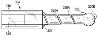
カテーテルを通る流体管腔のうちの1つ以上は、カテーテルの他の管腔の流体ポートから長手方向にずれている流体ポートを有し得る。例えば、図12に示されるように、カテーテル102は、カテーテルの終端遠位端に形成された流体ポート122Aまで延在する第1の流体管腔120Aを含み得る。カテーテル102はまた、カテーテルの遠位端から近位方向に距離Dだけ離間された流体ポート122Bまで延在する第2の流体管腔120Bを含み得る。示されるように、第2の流体管腔120Bは、1つ以上の側面向きポート122Bを含み得る。他の実施形態では、第2の流体管腔120Bは、遠位向きポートを含み得る。使用中、流体管腔120A、120Bのうちの一方を使用して薬物または他の流体を送達することができ、他方の流体管腔を使用して患者から流体を吸引することができる。したがって、カテーテル102を使用して標的部位に「プッシュプル」効果を作り出すことができ、薬物は、カテーテルの遠位端に第1の流体管腔120Aを介して注入され、次いで第2の流体管腔120Bを通って吸引される流体の流れによってカテーテルの近位端に向かって引き戻される。反対の配置を使用することもができ、薬物は、近位ポート(複数可)を通して注入され、遠位ポート(複数可)を通して吸引される。カテーテル102の近位端は、第1および第2の流体管腔120A、120Bにそれぞれ対応する第1および第2のコネクタ118A、118Bを有し得る。ずれた流体ポート122A、122Bを使用して、送達を自然CSF流などの患者の生理学的パラメータと調和させることができる。外部蠕動ポンプまたは他の装置を使用して注入および/または吸引を駆動することができる。示されるように、本体114の外側シース128は、第2の管腔120Bの終端後に第1の管腔120Aに向かって内向きにテーパ状をなし得る。
One or more of the fluid lumens through the catheter may have fluid ports that are longitudinally offset from the fluid ports of other lumens of the catheter. For example, as shown in FIG. 12,
カテーテル102は、カテーテルを通る流体の送達を制御するための特徴部を含み得る。例えば、図13に示されるように、カテーテル102は内部オーガ140を含み得る。オーガ140は、カテーテル102を通ってカテーテルの近位端まで延在する細長い可撓性シャフト142を有することができ、そこでオーガの回転を駆動するためのモータに連結することができる。モータは、コントローラ104の一部であり得るか、または別個の構成要素であり得る。コントローラ104は、オーガ140の回転を開始および停止することができ、ならびに/またはオーガが配設された流体管腔120を通る流体の送達を制御するようにオーガの回転スピードもしくは方向を制御することができる。オーガ140は、カテーテル102のシース部分128を通って延在する流体管132内に配設され得る。オーガ140は、オーガシャフト142が流体管を通って延在する状態で、流体管132の終端遠位端の遠位に配設することもできる。したがって、オーガ140は、カテーテル102のシース128内に配設され得るが、カテーテルの流体管132の遠位に配設され得る。オーガ140は、カテーテル102を通る流体の送達を有利に制御し、カテーテルからより乱流の流体を生成することができる。カテーテルの近位端は、第1および第2の流体管腔にそれぞれ対応する第1および第2のコネクタ118A、118Bと、第3のポートまたはコネクタ118Cとを有し得、第3のポートまたはコネクタ118Cを通ってオーガシャフト142が延在し得る。オーガ140を使用して、送達を自然CSF流などの患者の生理学的パラメータと調和させることができる。
さらなる例として、図14に示されるように、カテーテル102は、内部の往復運動するピストンまたは内部管144を含み得る。カテーテル102は、固定された外管128と、外管内に同軸に配設された摺動可能な内管144とを含み得る。内管144は、外管128に対して長手方向に並進するように構成され得る。内管144は、例えば、その内管の終端遠位端において弁146を含み得る例示的な弁としては、一方向弁、ダックビル弁、ばね付勢逆止弁などが挙げられる。シールは、内管144と外管128との間、例えば、カテーテル102の近位端に形成され得る。使用時には、内管144に薬物含有流体を充填することができる。次いで、内管144を外管128に対して近位方向に引っ張って、一方向弁146を通して、薬物含有流体を外管の遠位端に流すことができる。次いで、内管144を遠位方向に押し、一方向弁146を閉鎖して、薬物含有流体を外管128の遠位端から患者の中に放出することができる。並進運動する管128、144は、内管144の往復運動ごとに、薬物含有注入剤の一定量または所定の量を送達することを可能にすることができる。外管128および内管144の近位端は、例えば、外管および内管に流体を供給するためのコネクタ118A、118Bを含み得る。往復運動する内管144を使用して、送達を自然CSF流などの患者の生理学的パラメータと調和させることができる。
As a further example,
別の例として、図15に示されるように、カテーテル102は、カテーテルを通る薬物の送達を制御するのを助けるために、圧電変換器などの変換器148を含み得る。変換器148は、カテーテル102の流体ポート122に隣接して配設されたフレックス回路または他の基板上に形成され得る。変換器148は、そこからカテーテル102を通ってコントローラ104まで近位方向に延在する導電性のリード線またはワイヤ150を含み得る。使用時には、変換器148に電位を印加して変換器の振動または他の移動を誘発することができる。この移動はカテーテル102からの薬物の分布を制御することができる。例えば、変換器148は、注入剤がカテーテル102から出るときに注入剤が流れる方向を制御することができ、カテーテルの流体ポート122の開閉を制御することができ、および/またはカテーテルから出る注入剤の量を制御することができる。カテーテル102の近位端は、第1および第2の流体管腔にそれぞれ対応する第1および第2のコネクタ118A、118Bと、第3のポートまたはコネクタ118Cとを有し得、第3のポートまたはコネクタ118Cを通って変換器148の導電体150が延在し得る。変換器148を使用して、送達を自然CSF流などの患者の生理学的パラメータと調和させることができる。
As another example, as shown in FIG. 15,
システム100は、集束超音波を患者に送達するための1つ以上の変換器を含み得る。図16に示されるように、集束超音波システム152は、薬物含有注入剤154がカテーテル102から出る位置に向けて超音波を向けることができる。集束超音波は、薬物の分散を向上させ、かつ/または薬物が分散する方向および程度を制御することができる。集束超音波を使用して、送達を自然CSF流などの患者の生理学的パラメータと調和させることができる。集束超音波を使用して、拍動性送達なしに薬物分布を向上させるかまたは方向付けることもできる。
図17は、コントローラ104の例示的な実施形態の物理的構成要素のブロック構成を図示している。例示的なコントローラ104が本明細書に示され説明されているが、これは一般性および便宜のためであることが理解されよう。他の実施形態では、コントローラ104は、本明細書に示され説明されたものとはアーキテクチャおよび動作が異なり得る。コントローラ104は、タブレットコンピュータ、モバイル装置、スマートフォン、ラップトップコンピュータ、デスクトップコンピュータ、クラウドベースのコンピュータ、サーバコンピュータなどとすることができる。コントローラ104の1つ以上の部分を患者に移植することができる。送達制御ソフトウェアをコントローラ104上で実行することができる。ソフトウェアは、ローカルハードウェア構成要素(例えば、タブレットコンピュータ、スマートフォン、ラップトップコンピュータなど)上で実行することも、遠隔で(例えば、コントローラと通信連結しているサーバまたはクラウド接続型コンピューティング装置上で)実行することもできる。
FIG. 17 illustrates a block diagram of the physical components of an exemplary embodiment of
図示のコントローラ104は、例えば、埋め込まれたソフトウェア、オペレーティングシステム、装置ドライバ、アプリケーションプログラムなどを実行することによってコントローラ104の動作を制御するプロセッサ156を含む。プロセッサ156は、プログラム可能な汎用もしくは特殊用途のプロセッサおよび/または様々な専用もしくは市販の単一または複数のプロセッサシステムのうちのいずれかを含む、任意のタイプのマイクロプロセッサまたは中央処理ユニット(CPU)を含み得る。本明細書で使用される場合、プロセッサという用語は、マイクロプロセッサ、マイクロコントローラ、ASIC、FPGA、PIC、内部もしくは外部のメモリまたはレジスタからプログラム命令を読み取り、解釈するプロセッサなどを指すことができる。コントローラ104はまた、メモリ158を含み、メモリ158は、プロセッサ156によって実行されるコードまたはプロセッサによって処理されるデータのための一時的なもしくは恒久的なストレージを提供する。メモリ158は、読み取り専用メモリ(ROM)、フラッシュメモリ、1つ以上の様々なランダムアクセスメモリ(RAM)、および/またはメモリ技術の組み合わせを含み得る。コントローラ104の様々な構成要素は、任意の1つ以上の別個のトレース、物理的バス、通信線などを介して相互接続することができる。
The illustrated
コントローラ104はまた、通信インターフェースまたはI/Oインターフェースなどのインターフェース160を含み得る。通信インターフェースは、コントローラ104がネットワークまたは通信バス(例えば、ユニバーサルシリアルバス)を介して遠隔装置(例えば、他のコントローラまたはコンピュータシステム)と通信することを可能にすることができる。I/Oインターフェースは、1つ以上の入力装置と、1つ以上の出力装置と、コントローラ104の様々な他の構成要素との間の通信を容易にし得る。例示的な入力装置としては、タッチスクリーン、機械式ボタン、キーボード、および指示装置が挙げられる。コントローラ104はまた、ストレージ装置162をも含み得、そのストレージ装置は、不揮発性および/または非一時的な様態でデータを格納するための任意の従来の媒体を含み得る。したがって、ストレージ装置162は、データおよび/または命令を持続状態で保持し得る(すなわち、コントローラ104への電力の中断にもかかわらず、値は維持される)。ストレージ装置162は、1つ以上のハードディスクドライブ、フラッシュドライブ、USBドライブ、光学ドライブ、様々な媒体のディスクもしくはカード、および/またはそれらの任意の組み合わせを含むことができ、コントローラ104の他の構成要素に直接接続され得るか、またはそれらに通信インターフェースなどを介して遠隔接続され得る。コントローラ104は、ディスプレイ164も含むことができ、その上に表示される画像を生成することができる。いくつかの実施形態では、ディスプレイ164は、真空蛍光ディスプレイ(VFD)、有機発光ダイオード(OLED)ディスプレイ、または液晶ディスプレイ(LCD)であり得る。コントローラ104はまた、電源166と、適切な規制および調整回路とを含み得る。例示的な電源としては、ポリマーリチウムイオン電池などの電池、またはコントローラ104をDCもしくはAC電力源に連結するためのアダプタ(例えば、USBアダプタもしくは壁アダプタ)が挙げられる。
コントローラ104によって遂行される様々な機能は、1つ以上のモジュールによって遂行されるものとして論理的に記載され得る。かかるモジュールをハードウェア、ソフトウェア、またはそれらの組み合わせで実装することができることが理解されよう。ソフトウェアで実装される場合、モジュールは単一のプログラムまたは1つ以上の別個のプログラムの一部とすることができ、(例えば、埋め込まれたソフトウェアパッケージ、オペレーティングシステム、装置ドライバ、スタンドアロンアプリケーション、および/またはそれらの組み合わせの一部として)様々な状況で実装することができることがさらに理解されよう。加えて、1つ以上のモジュールを具現化するソフトウェアは、1つ以上の非一時的なコンピュータ可読ストレージ媒体上に実行可能なプログラムとして格納され得る。特定のモジュールによって遂行されるものとして本明細書に開示されている機能を他の任意のモジュールまたはモジュールの組み合わせによって遂行することもでき、コントローラは、本明細書に示され説明されたものよりも少ないかまたは多いモジュールを含むことができる。図18は、コントローラ104の1つの例示的な実施形態のモジュールの概略図である。
Various functions performed by
図18に示されるように、コントローラ104は、センサ(複数可)108から情報を受信するように構成されたセンサ入力モジュール168を含み得る。センサ入力モジュール168は、例えば、プロセッサの汎用入出力ピンを介して、センサ108からプロセッサ156に供給される出力信号を読み取り、解釈することができる。センサ入力モジュール168は、周波数検出、位相検出、デバウンシング、アナログ-デジタル変換、フィルタリングなど、センサ信号に対する様々な処理を任意選択で遂行することができる。
As shown in FIG. 18,
コントローラ104はまた、患者から流体を注入もしくは吸引するようにポンプまたはアクチュエータ106を制御し、かつ/またはカテーテル102を制御するように構成された送達制御モジュール170(例えば、オーガ、ピストン、変換器、超音波システムなど)を含み得る。例えば、「注入」命令が発行されると、送達制御モジュール170は、カテーテル102を通して注入剤をポンピングし始めるように電力をポンプ106に供給させるか、または圧力下で格納された注入剤がカテーテルと流体連通して設置され、それを通って流れるように電子作動弁を開放させることができる。いくつかの実施形態では、送達制御モジュール170は、システム内の圧力が所定の閾値量に到達したことを圧力センサが示したときにポンプ106への電力を遮断するかまたは弁を閉鎖するように構成され得る。「吸引」命令が発行されると、送達制御モジュール170は、カテーテル102から流体をポンピングし始めるように電力をポンプ106に供給させることができる。
The
コントローラ104は、例えば、インターフェース160を介してユーザによって供給される1つ以上のユーザ入力を受信するように構成されたユーザ入力モジュール172を含み得る。例示的なユーザ入力としては、以下でさらに論じられるように、注入パラメータ、患者情報、処置プロトコルなどが挙げられ得る。
コントローラ104はまた、グラフィカルまたはテキストのユーザインターフェース、メニュー、ボタン、命令、および他のインターフェース要素などの様々な情報をディスプレイ164上でユーザに表示するように構成された表示モジュール174を含み得る。表示モジュール174は、命令、警告、エラー、測定、および計算を表示するように構成することもできる。
図19は、表示モジュール174によってユーザに表示され得る例示的なグラフィカルユーザインターフェース176を図示しており、それを介してユーザは、ユーザ入力モジュール172に情報を供給することができる。図示のインターフェース176は、カテーテル102に注入剤を送達するため、およびカテーテルから流体を回収または吸引するためにそれぞれのシリンジポンプに力を付加するように動作することができる第1および第2のモータまたはリニアアクチュエータを含むポンプシステム106と共に使用するために構成されている。
FIG. 19 illustrates an exemplary
ユーザインターフェース176は、モータに関連する様々な情報を表示するためのモータ通信パネル178を含み得る。この情報は、モータの接続状態、モータのIPまたは他のソフトウェアアドレス、およびモータの通信周波数または更新時間を含み得る。ユーザは、モータ通信パネル178と対話して、モータアドレスおよび更新時間を選択または変更することができる。
ユーザインターフェース176は、様々なモータ設定を調節し、現在の設定をユーザに表示するためのモータ設定パネル180を含み得る。モータ設定パネル180は、モータ速度、モータ加速度、モータ段の関数としてのシリンジ移動距離、現在のモータ位置、注入頻度、注入振幅、注入割合、注入位相などの制御を含み得る。
The
コントローラ104は、様々な注入および/または吸引パラメータを制御して、カスタマイズされた送達を達成するように構成され得る。これにより、治療用途に基づいて送達を調整することが可能になり得る。コントローラ104によって制御され得る例示的なパラメータとしては、注入タイプ、注入割合、注入量、注入間の時間、振動数、注入と回収の割合、注入位相タイミング、吸引タイプ、吸引割合、吸引間の時間、吸引量などが挙げられる。
ポンプまたはアクチュエータシステム106は、薬物または薬物含有流体をカテーテル102に供給し、かつ/またはカテーテルから流体を吸引するように構成され得る。システム106は、1つ以上のポンプを含み得る。例えば、システム106は、各々がカテーテル102の対応する管腔と関連付けられて流体連通する複数のポンプを含み得る。ポンプはまた、ある量の流体を保持するために、それぞれのリザーバと関連付けられて流体連通することができる。いくつかの実施形態では、システム106は、コントローラ104から受信した制御信号に応答してシリンジポンプのプランジャを前進または後退させるように構成された電子リニアアクチュエータに連結された第1および第2のシリンジポンプを含み得る。いくつかの実施形態では、システム106は、蠕動ポンプ、オーガポンプ、ギアポンプ、ピストンポンプ、ブラダーポンプなどを含み得る。システム106の1つ以上の部分を患者に移植することができる。システム106は、様々な埋め込み型または体外式ポンプのうちのいずれかを含み得る。いくつかの実施形態では、システム106は、完全埋め込み型のプログラム可能なポンプと、システムを使用して送達される流体を含有する完全埋め込み型の流体リザーバとを含み得る。いくつかの実施形態では、システム106全体を、例えば、慢性処置の方法を容易にするために埋め込み型にすることができる。
Pump or
センサ108は、単一のセンサであっても、複数のセンサであってもよい。例示的なセンサとしては、圧力センサ、心電図センサ、心拍数センサ、温度センサ、PHセンサ、呼吸数センサ、呼吸量センサ、肺活量センサ、胸部拡張および収縮センサ、胸腔内圧力センサ、腹腔内圧力センサなどが挙げられる。センサ108のうちの1つ以上を患者に移植することができる。センサ108のうちの1つ以上をカテーテル102上に装着すること、それを通して挿入すること、またはその内もしくはその上に形成することができる。センサ108はまた、カテーテル102から離れていてもよい。いくつかの実施形態では、センサ108は、カテーテル102内またはその上に配設された、カテーテルに隣接してCSF圧力を測定するための圧力センサと、患者の心拍数を測定するためのECGセンサとを含み得る。センサ108は、(有線接続を介してまたは無線接続を介して)コントローラ104のセンサ入力モジュール168に接続され得る。
上記のように、送達システム100の1つ以上の構成要素、およびいくつかの実施形態では、送達システムのすべての構成要素を患者に移植することができる。送達システム100の一部または全部を移植することは、非侵襲的または外来処置を介して(例えば、数日間、数週間、数ヶ月間、または数年間にわたる)慢性または長期薬物送達を容易にすることができる。
As noted above, one or more components of the
図20Aおよび20Bは、患者に完全に移植されたカテーテル102を図示している。示されるように、カテーテル102は、患者の髄腔内空間内に位置決めするように構成され得、脊柱の実質的に全長にわたってまたはその任意の部分に沿って延在し得る。カテーテル102は、1つ以上の流体管腔を含み得る。カテーテル102はまた、1つ以上の流体ポートを含み得る。いくつかの実施形態では、カテーテル102は、複数の流体管腔を含み得、複数の流体管腔の各々は、それ自体のそれぞれの流体ポートを有する。図示の実施形態では、カテーテル102は、3つの流体管腔と3つのそれぞれの流体ポート122P、122M、および122Dとを含む。カテーテル102はまた、1つ以上のセンサ108(例えば、圧力センサ)を含み得る。図示の実施形態では、流体ポート122P、122M、122Dの各々は、それに隣接してまたは近接して装着されたセンサ108P、108M、108Dを含む。カテーテル102の近位端は、完全に埋め込まれた経皮式または体外式注入ポート182に結合され得、その注入ポートを通して流体がカテーテルの様々な管腔に送達され(またはそこから除去され)得、またその注入ポートを通してカテーテル上の1つ以上のセンサ108が、コントローラ104または他の装置に結合され得る。クイックコネクタシステム184を使用してカテーテル102を注入ポート182に連結することができる。マイクロコネクタ184は、空気および/または細菌フィルタを含むことができ、ゼロデッドボリュームコネクタとすることができる。ポンプ106およびコントローラ104は、注入ポート182と嵌合するように構成された注射器190に連結され得る、図20Cに示されるようなシャーシまたはハウジング188内に一緒に装着され得る。注射器190は、注射器が皮下注入ポート182に対して正確に位置合わせされることを確実にするための磁気位置合わせ特徴部186を含み得る。
Figures 20A and 20B illustrate
図20Dに示されるように、カテーテル102の遠位または頭側/頸部先端は、それを通る乱流を助長する修正された形状を有し得る(例えば、上記のような螺旋状またはコルク抜きの形状の管腔または流体ポート122D)。他の様々な形状のうちのいずれも使用することができる。他のポート122M、122Pも同様に構成することができ、図20Eに示されるように単純な円形断面を有することができるか、または本明細書に記載される他の任意の構成を有することができる。
As shown in FIG. 20D, the distal or cranial/neck tip of
図20A~20Eに図示されるシステム100は、様々な方法のうちのいずれかで急性および/または慢性用途に使用することができる。
The
例えば、カテーテル102を使用して、3つの異なる薬物(例えば、カテーテルの各異なる管腔を通して1つの薬物)を送達することができる。
For example,
さらなる例として、カテーテル102は、脊椎の異なる区域への異なる薬物の局所送達のために使用され得る。
As a further example,
さらに別の例として、カテーテル102を使用して、脊柱全体に沿って実質的に瞬的分布で同じ薬物を送達することができる。
As yet another example,
別の例では、注入された流体を脊柱管を通して汲み出すために、カテーテル102の1つのポートを、別のポートが注入するために使用されている間に、吸引するために使用することができる。いくつかの実施形態では、流体を下部腰部ポート122Pを通して注入することができ、流体を頸部ポート122Dを通して吸引して注入された流体を脊柱まで「引っ張る」ことができる。
In another example, one port of the
別の例では、流体を患者の脊椎の頸部領域に配設されたポート122Dを通して注入して、注入された薬物を頭蓋腔に進ませることができる。
In another example, fluid can be injected through
さらなる例として、カテーテル102を使用して、注入された薬物を脊椎の所与の区域に実質的に収容することができる。いくつかの実施形態では、流体は、下部腰部ポート122Pを通して注入され得、流体は、中間腰部ポート122Mから回収されて、注入された薬物を患者の脊椎の腰部領域の2つのポート122Pと122Mとの間に保つことができる。
As a further example,
例示的な方法では、多重管腔およびポートを介した注入および吸引を段階的に行うかまたは順番に組み合わせて、改善されて制御された都合のよい割合でかなりのボーラスを作り出して前進させることができる。この方法は、意図的に隔置されたポート間の同時の吸引/注入を含み得る。ボーラスを前進させるときの後の手技段階で置き換えられる安全な量のCSFを除去する調製段階によって送達を向上させることができる。この方法は、同期された拍動性注入の最終段階を含み得る。この方法は、大きなボーラスがより迅速に形成されることを可能にすること、制御された投与を可能にすること、および/またはボーラスが脳または他の標的部位により近く送達されることを可能にすることができる。この方法は、近位端から遠位端に向かってテーパ状をなすカテーテルを使用して遂行され得る。カテーテルの直径が各ポートの遠位方向で低減するテーパ状のカテーテルのプロファイルは、カテーテルをより長くすることを可能にし、導入/ナビゲートすることをより容易にし、装置を標的部位のかなり近くに到達させることを可能にすることができる。ポートの設計と位置は、投与量および他の要因に基づいて最適化され得る。カテーテルから出るときに注入剤の乱流を促進するために、ポートから出る流体が患者の解剖学的構造(例えば、管腔盲端(blind lumen end)、管腔側壁、または管腔狭窄)に対して流れるようにカテーテルを設置することができる。初期段階では、患者CSFのある量をカテーテルの1つ以上のポートを通して吸引することができる。例示的な実施形態では、患者のCSFの約10体積%をカテーテルを通して吸引し、リザーバに格納することができる。吸引されるCSFの量は、臨床的に判定された安全なレベルに基づき得る。後続の送達ステップでは、CSFはカテーテル102の遠位流体ポート122Dを通して患者から吸引され、同時に薬物はカテーテルの中間ポート122Mを通して患者に注入される。これにより、薬物のボーラスを中間ポート122Mと遠位ポート122Dとの間に形成することができる。ポートは、ボーラスサイズまたは投与量を画定するようにカテーテルの長さに沿って位置し得る。前進ステップでは、薬物のボーラスを患者内で前進させることができる。これは、以前に吸引されたCSFをリザーバから患者にカテーテル102の近位ポート122Pを通して注入することによって達成され得る。この注入は、ボーラスを標的部位に向かって遠位方向に促すことができ、正常または安全なCSF圧力が患者内で到達されるまで続けることができる。上記の例ではボーラスを前進させるために以前に吸引されたCSFが使用されているが、その代わりにまたはそれに加えて、薬物含有流体などの他の流体を使用することができる。ボーラスの前進前、前進中、または前進後に、患者の1つ以上の生理学的パラメータと調和させて、CSFおよび/または薬物含有流体の注入を拍動的な様態で遂行することができる。上記の方法を近位ポート122Pおよび遠位ポート122Dのみを使用して遂行することもできる。近位ポート122P、中間ポート122M、および遠位ポート122Dは、図20Aに示されるように脊柱の長さに沿って隔置すること、または脊椎の別々の領域(例えば、頸部脊椎、胸部脊椎、腰部脊椎など)にすべて収容することもできる。
In an exemplary method, infusion and aspiration through multiple lumens and ports may be staged or combined in sequence to create and advance a substantial bolus at an improved controlled and convenient rate. can. The method may include simultaneous aspiration/infusion between ports intentionally spaced apart. Delivery can be improved by preparation steps that remove safe amounts of CSF that are replaced in later procedural steps when advancing the bolus. The method may include a final stage of synchronized pulsatile injection. This method allows large boluses to be formed more quickly, allows for controlled administration, and/or allows the bolus to be delivered closer to the brain or other target sites. can do. This method may be performed using a catheter that tapers from its proximal end to its distal end. The tapered catheter profile, where the catheter diameter decreases distally of each port, allows the catheter to be longer, makes it easier to introduce/navigate, and brings the device much closer to the target site. can make it possible to reach Port design and location may be optimized based on dosage and other factors. To facilitate turbulent flow of the infusate as it exits the catheter, the fluid exiting the port must be directed against the patient's anatomy (e.g., blind lumen end, lumen sidewall, or lumen stenosis). A catheter can be placed to flow against it. In the initial phase, a volume of patient CSF can be aspirated through one or more ports of the catheter. In an exemplary embodiment, about 10% by volume of the patient's CSF can be aspirated through the catheter and stored in the reservoir. The amount of CSF aspirated may be based on clinically determined safe levels. In a subsequent delivery step, CSF is aspirated from the patient through
本明細書に開示されているシステムは、様々な薬物送達方法のいずれにも使用することができる。 The systems disclosed herein can be used with any of a variety of drug delivery methods.
例示的な方法では、注入ポンプ106は、カテーテル102を通って患者内に(例えば、患者の髄腔内空間に)薬物または薬物含有流体をポンピングするように構成され得る。様々な位置のうちのいずれかでカテーテル102を患者に挿入することができる。例えば、経皮的穿刺は、針を使用して患者内に形成され得る。穿刺は、脊椎の腰部領域に、または脊椎の任意の他の領域、例えば、C1とC2間の頸部領域に形成され得る。針は、カテーテル102を脊髄と平行になるように操縦するのを助ける屈曲遠位先端を有し得る。カテーテル102は、針を通して挿入され、脊髄に沿って髄腔内空間を通って誘導され得る。注入は、経皮的穿刺に近接して遂行され得るか、またはカテーテル102が患者内でいくらか前進され得る。いくつかの実施形態では、カテーテル102を腰部脊椎に挿入し、頸部脊椎または大槽に前進させることができる。注入は、カテーテル102の長さに沿った任意の点で遂行され得る。流体をカテーテル102の遠位端から(例えば、脊椎の頸部領域に)注入することができ、カテーテルを近位方向に回収することができ、さらに注入をより尾側の位置で(例えば、脊椎の腰部領域において)遂行することができる。
In an exemplary method,
ポンプ106をコントローラ104によって制御して、薬物の送達を患者の自然CSF流れもしくは拍動と、または患者の他の生理学的パラメータ(例えば、心拍数、呼吸数、肺活量、胸部拡張および収縮、胸腔内圧力、腹腔内圧力など)と同期させるか、または別様に調和させることができる。注入プロファイルは、注入剤を標的部位まで駆動させるために、自然CSF拍動を無効にするように調整され得る。代替的にまたは追加的に、注入プロファイルは、注入剤を標的部位に向かって移動させるために、自然CSF拍動と調和させて、それを活用するように調整され得る。
圧力センサ108からの読み取り値は、患者のCSF流の様々な特性(例えば、位相、割合、大きさなど)を判定するためにセンサ出力に対して信号処理を遂行し得るコントローラ104によって受信され得る。次いで、コントローラ104は、これらの測定された特性に基づいてポンプ106を制御して、自然CSF流と調和させて薬物を送達し、任意選択でリアルタイムで送達を同期させることができる。例えば、図21Aの上部に示されるように、コントローラ104は、測定されたCSFの拍動性の流れを正弦波近似に変換することができる。次いで、コントローラ104は、図21Aの下部に示すように、CSF拍動と連携して注入ポンプ106を駆動するためのポンプ制御信号を出力することができる。
Readings from
場合によっては、圧力センサ108によって感知された圧力は、カテーテル102を通る注入によって影響を受ける可能性がある。したがって、CSF流を検出または推定する別の方法があることが望ましい場合がある。したがって、いくつかの実施形態では、システム100は、(例えば、コントローラと通信連結しているECGセンサ108によって検出されるときに)注入が行われず、コントローラ104がCSF拍動と心拍数との間の相関関係を確立する「学習」モードで最初に動作させることができる。概して、CSF拍動は、わずかな遅延を伴って心拍数を追跡する。一旦相関関係が確立されると、システム100は、注入剤がカテーテル102を通って送達され、CSF拍動が(圧力センサ108の出力に基づいてCSF拍動を検出もしくは推定するのではなく、またはそれに加えて)測定された心拍数に基づいて検出または推定される「注入」モードで動作され得る。言い換えれば、システム100は、必ずしも圧力センサの出力に頼ることなく、ECG出力に基づいてCSF流を補間または推定することができる。これにより、圧力センサを注入圧力の監視などの他の目的のために使用して、コントローラ104が送達を標的とする圧力または圧力範囲まで自動的に規制することを可能にすることができる。
In some cases, the pressure sensed by
本明細書に記載されるシステムの使用の一例では、薬物は、次に脊柱に沿って緩徐に正確に拡散する単純なボーラス注入(ある量の流体の急速注入)を介して髄腔内空間に送達され得る。 In one example of use of the systems described herein, the drug is injected into the intrathecal space via a simple bolus injection (rapid injection of a volume of fluid) that then diffuses slowly and precisely along the spinal column. can be delivered.
別の例では、ボーラス注入を遂行して薬物を送達した後に、自然CSFパルスを無効にし、標的位置(例えば、脳)に向かってボーラスをより迅速に移動させるために、システムを使用して、振動数/拍動数を変化させることによってボーラスの後ろに拍動を作り出すことができる。ある量のCSFを繰り返し回収または吸引し、次いでその同じ量を患者内に再度ポンピングしてパルスを作り出すことによって拍動を作り出すことができる。 In another example, after performing a bolus infusion to deliver drug, the system is used to override the spontaneous CSF pulse and move the bolus more quickly toward the target location (e.g., brain). A beat can be created behind the bolus by varying the frequency/beat rate. A beat can be created by repeatedly withdrawing or aspirating a volume of CSF and then pumping that same volume again into the patient to create a pulse.
別の例では、薬物自体の注入を使用して拍動効果を作り出して、薬物を髄腔内空間に沿って促すことができる。この例では、第1の量の薬物(例えば、0.1ml)を注入することができ、次いで、第2の、より少ない量(例えば、0.05ml)を回収することができる。これを繰り返して、各サイクルで正味注入を伴うパルスを作り出すことができる。所望の投与量が送達されるまでプロセスを繰り返すことができる。2:1の注入対回収の割合が上で論じられているが、任意の割合が使用され得ることが理解されよう。加えて、注入と回収の割合は、標的位置(例えば、脊柱の頂部)に向かって流体のバーストを作り出すように(例えば、迅速に注入し、緩徐に回収することによって)制御され得る。 In another example, injection of the drug itself can be used to create a pulsatile effect to urge the drug along the intrathecal space. In this example, a first volume of drug (eg, 0.1 ml) can be injected and then a second, smaller volume (eg, 0.05 ml) can be withdrawn. This can be repeated to create pulses with net injection at each cycle. The process can be repeated until the desired dose is delivered. Although a 2:1 injection to withdrawal ratio is discussed above, it will be appreciated that any ratio can be used. Additionally, the rate of injection and withdrawal can be controlled (eg, by injecting quickly and withdrawing slowly) to create a burst of fluid toward a target location (eg, the top of the spinal column).
本明細書に開示される装置および方法では、注入および/または吸引を患者の1つ以上の生理学的パラメータ(例えば、自然CSF流、心拍数、呼吸数など)と調和させることができる。 The devices and methods disclosed herein allow infusion and/or aspiration to be matched with one or more physiological parameters of the patient (eg, natural CSF flow, heart rate, respiration rate, etc.).
CSF流のタイミングに対して薬物が送達されるタイミングに基づいて、髄腔内標的部位における薬物分布の方向を少なくともある程度制御することができる。例えば、図21Bに示されるように、CSF流の上昇波と同期している注入は、頭側の方向により大きな程度に分布され得るが、図21Cに示されるように、CSF流の下降波と同期している注入は、脊柱管の尾側の方向により大きな程度に分布され得る。 Based on the timing of drug delivery relative to the timing of CSF flow, the direction of drug distribution at the intrathecal target site can be controlled at least in part. For example, an injection synchronous with an ascending wave of CSF flow, as shown in FIG. Synchronous injections can be distributed to a greater extent in the caudal direction of the spinal canal.
いくつかの実施形態では、二重管腔または多重管腔カテーテルを交互の反復注入および吸引のために使用することができ、それによって薬物分布をさらに向上させることができる。 In some embodiments, a dual-lumen or multi-lumen catheter can be used for alternating repeated infusions and aspirations, thereby further improving drug distribution.
本明細書に開示されるシステムおよび方法は、脊柱管または脳の遠隔部分に効率的に到達しない(仮にあったとしても)伝統的な腰部ボーラス注入と比較して、薬物を髄腔内空間に送達するための改善された手段を提供し得る。 The systems and methods disclosed herein deliver drugs to the intrathecal space compared to traditional lumbar bolus injections, which do not (if at all) efficiently reach the spinal canal or remote parts of the brain. It may provide improved means for delivery.
上記の実施例には髄腔内送達が概して記載されているが、本明細書のシステムおよび方法は、当業者によって理解されるように、サイズまたは他のパラメータの適切な修正を伴って他の用途で使用され得ることが理解されよう。例えば、本明細書に開示されるシステムおよび方法は、動脈内または静脈内送達に使用され得る。かかるシステムおよび方法は、患者の1つ以上の生理学的パラメータ(例えば、自然CSF流、心拍数、呼吸数など)と調和した注入および/または吸引を含み得る。 Although intrathecal delivery is generally described in the above examples, the systems and methods herein can be applied to other delivery systems with appropriate modifications of size or other parameters, as will be appreciated by those skilled in the art. It will be appreciated that it can be used in any application. For example, the systems and methods disclosed herein can be used for intra-arterial or intravenous delivery. Such systems and methods may include infusion and/or aspiration in harmony with one or more physiological parameters of the patient (eg, natural CSF flow, heart rate, respiration rate, etc.).
いくつかの実施形態では、薬物は、非拍動的な様態で、および/または必ずしも送達を患者の生理学的パラメータと調和させることなく送達され得る。例えば、交互の、または別様に調和された吸引および注入を使用して、薬物を標的部位に送達することができる。さらなる例として、薬物を注入し、次いで緩衝剤を薬物の後ろに注入して分布を向上させるか、または薬物を標的部位に向かって移動させることができる。 In some embodiments, the drug may be delivered in a non-pulsatile manner and/or without necessarily matching the delivery with the patient's physiological parameters. For example, alternating or otherwise coordinated aspiration and infusion can be used to deliver the drug to the target site. As a further example, the drug can be injected and then a buffering agent can be injected behind the drug to improve distribution or move the drug towards the target site.
例示的な方法は、カテーテルの少なくとも一部分を患者に挿入することと、薬物を患者の標的領域に送達することとを含み得る。カテーテルの少なくとも一部分を標的領域に配設することができる。薬物は、拍動的な様態で送達することができる。薬物は、患者の生理学的パラメータ(例えば、患者の自然CSF流および/または患者の心拍数)と調和させて送達することができる。 An exemplary method can include inserting at least a portion of a catheter into a patient and delivering a drug to a target area of the patient. At least a portion of the catheter can be disposed in the target area. Drugs can be delivered in a pulsatile manner. The drug can be delivered in concert with the patient's physiological parameters (eg, the patient's natural CSF flow and/or the patient's heart rate).
標的領域は、患者の髄腔内空間であり得る。標的領域は、患者の軟膜下領域(例えば、脊髄の軟膜下領域および/または脳の軟膜下領域)であり得る。標的領域は、患者の小脳であり得る。標的領域は、患者の歯状核であり得る。標的領域は、患者の後根神経節であり得る。標的領域は、患者の運動神経細胞であり得る。薬物は、アンチセンスオリゴヌクレオチドを含み得る。薬物は、立体的に純粋な核酸を含み得る。薬物は、ウイルスを含み得る。薬物は、アデノ随伴ウイルス(AAV)を含み得る。薬物は、非ウイルス遺伝子治療を含み得る。薬物は、ベキソソームを含み得る。薬物は、リポソームを含み得る。この方法は、薬物を送達することによって(例えば、AAVなどのウイルスを送達することによって)遺伝子治療を遂行することを含み得る。この方法は、薬物を送達することによって(例えば、AAVなどのウイルスを送達することによって)遺伝子編集を遂行することを含み得る。この方法は、薬物を送達することによって(例えば、AAVなどのウイルスを送達することによって)遺伝子スイッチを遂行することを含み得る。この方法は、薬物を送達することによって(例えば、ベキソソームおよび/またはリポソームを送達することによって)非ウイルス遺伝子治療を遂行することを含み得る。 The target area can be the patient's intrathecal space. The target area can be the patient's subpial region (eg, the subpial region of the spinal cord and/or the subpial region of the brain). The target region can be the patient's cerebellum. The target area can be the patient's dentate nucleus. The target area can be the patient's dorsal root ganglion. The target area can be the patient's motor neurons. Drugs may include antisense oligonucleotides. A drug may comprise a sterically pure nucleic acid. Drugs may include viruses. The drug may include adeno-associated virus (AAV). Drugs may include non-viral gene therapy. The drug may include bexosomes. Drugs may include liposomes. The method may involve performing gene therapy by delivering drugs (eg, by delivering viruses such as AAV). The method can include effecting gene editing by delivering drugs (eg, by delivering viruses such as AAV). The method may involve effecting gene switching by delivering drugs (eg, by delivering viruses such as AAV). The method may involve performing non-viral gene therapy by delivering drugs (eg, by delivering vexosomes and/or liposomes).
いくつかの実施形態では、この方法は、患者の総CSF量を判定することと、総CSF量に基づいて送達を調整することとを含み得る。例えば、コントラストの有無にかかわらず、MRIまたは他の撮像技術を使用して、患者の全CSF量を評価することができる。次いで、測定された量に基づいて薬物の送達を調整することができる。例えば、より大きな総CSF量を有する患者にはより大きな量の緩衝剤を使用することができ、より小さな総CSF量を有する患者にはより小さな量の緩衝剤を使用することができる。さらなる例として、注入振幅、注入速度、吸引量、吸引振幅、および他のパラメータは、測定された総CSF量に従って変化し得る。 In some embodiments, the method can include determining the patient's total CSF volume and adjusting delivery based on the total CSF volume. For example, MRI or other imaging techniques, with or without contrast, can be used to assess a patient's total CSF volume. Delivery of the drug can then be adjusted based on the amount measured. For example, a patient with a larger total CSF volume can use a larger amount of buffering agent, and a patient with a lower total CSF volume can use a smaller amount of buffering agent. As a further example, infusion amplitude, infusion rate, aspiration volume, aspiration amplitude, and other parameters may vary according to the measured total CSF volume.
注入量は、約0.05mL~約50mLの範囲であり得る。注入割合は、約0.5mL/分~約50mL/分の範囲であり得る。 Injection volumes can range from about 0.05 mL to about 50 mL. Infusion rates can range from about 0.5 mL/minute to about 50 mL/minute.
以下は、本明細書に開示されるシステムを使用して遂行され得る例示的な薬物送達方法である。 The following are exemplary drug delivery methods that can be accomplished using the systems disclosed herein.
実施例A:
薬物(ポンプ1)と緩衝剤/生理食塩水(ポンプ2)の交互の拍動性注入
薬剤の総量:2.2mL
緩衝剤の総量:4.4mL
両ポンプの注入割合:15mL/分
サイクル数:腰部で10サイクル、その後、大槽で10サイクル
サイクル間の時間:100ミリ秒
注入の説明:腰部において、ポンプ1は、15mL/分で0.11mLを注入し、100msの休止、ポンプ2は、15mL/分で0.22mLを注入し、100msの休止(サイクル1)。これを腰部で合計10サイクル繰り返す。カテーテルは大槽まで螺合する。ポンプ1は、15mL/分で0.11mLを注入し、100msの休止、ポンプ2は、15mL/分で0.22mLを注入し、100msの休止(サイクル1)。これを大槽で合計10サイクル繰り返す。
Example A:
Total volume of alternating pulsatile infusion of drug (pump 1) and buffer/saline (pump 2): 2.2 mL
Total volume of buffer: 4.4 mL
Infusion rate for both pumps: 15 mL/min Number of cycles: 10 cycles in the lumbar area, then 10 cycles in the cisterna magna Time between cycles: 100 ms and 100 ms pause, pump 2 injects 0.22 mL at 15 mL/min, 100 ms pause (cycle 1). Repeat this on the lower back for a total of 10 cycles. The catheter is threaded up to the cisterna magna.
実施例B:
薬物(ポンプ1)と緩衝剤/生理食塩水(ポンプ2)の交互の拍動性注入
薬物総量:3mL
緩衝剤総量:20mL
両方のポンプの注入速度:4mL/分
サイクル:胸部で13サイクル
ポンプ1とポンプ2とを交互する間の時間:1000ミリ秒
サイクル間の時間(ポンプ2からポンプ1まで):5000ミリ秒
注入の説明:腰部において、ポンプ1は、4mL/分で0.231mLを注入し、1000msの休止、ポンプ2は、4mL/分で2.0mLを注入し、5000msの休止(サイクル1)。これを胸部領域で合計13サイクル繰り返す。
Example B:
Alternating pulsatile infusion of drug (pump 1) and buffer/saline (pump 2) Total drug volume: 3 mL
Total amount of buffer: 20 mL
Infusion rate for both pumps: 4 mL/min Cycles: 13 cycles on chest Time between alternating
実施例C:
薬物(ポンプ1)と緩衝剤/生理食塩水(ポンプ2)の交互の拍動性注入
薬剤の総量:5mL
緩衝剤の総量:8mL
ポンプ1の注入割合:37mL/分
ポンプ2の注入割合:20mL/分
サイクル:胸部領域で5サイクル
サイクル間の時間:10ミリ秒
注入の説明:腰部において、ポンプ1は、37mL/分で1mLを注入し、10msの休止、ポンプ2は、30mL/分で1.6mLを注入し、100msの休止(サイクル1)。これを胸部領域で合計5サイクル繰り返す。
Example C:
Total volume of alternating pulsatile infusion of drug (pump 1) and buffer/saline (pump 2): 5 mL
Total volume of buffer: 8 mL
Infusion rate for pump 1: 37 mL/min Infusion rate for pump 2: 20 mL/min Cycles: 5 cycles in the chest area Time between cycles: 10 ms Infusion description: In the lower back, pump 1 injects 1 mL at 37 mL/min Infuse, 10 ms pause, pump 2 infuses 1.6 mL at 30 mL/min, 100 ms pause (cycle 1). This is repeated for a total of 5 cycles in the chest area.
図22は、腰部穿刺針292を含む薬物送達システム200を図示している。針292は、針の遠位先端に隣接して装着されたセンサ294(例えば、圧力センサ)を含み得る。したがって、針292を患者210に挿入すると、センサ294は患者のCSFの圧力または他の特性を測定することができる。針292はまた、センサ294の出力をユーザに表示するための一体型または遠隔ディスプレイ296を含み得る。いくつかの実施形態では、ディスプレイ296は、針292の長さに沿って、針の近位ルアーまたは他のコネクタ298の遠位に装着され得る。針本体292は、鋭利なまたは角度を付けた先端を有する管状金属シャフトであり得る。流体配管は、例えば、近位コネクタ298を介して針292に、かつプログラム可能なポンプ106に連結され得る。上記のタイプのコントローラ104は、例えば、患者の生理学的パラメータと調和させて拍動的な様式で、針292を通して流体を送達するようにポンプ106を制御するようにプログラムされ得る。針292を使用して、薬物を送達すること、緩衝剤を送達すること、および/または流体を吸引することができる。いくつかの実施形態では、上記のタイプのカテーテル102を針292を通して挿入することができ、流体送達または吸引をカテーテルを通して遂行することができる。
FIG. 22 illustrates a
図23に示されるように、図22に示されるプログラム可能なポンプ106およびコントローラ104の代わりにまたはそれに加えて、手動ポンプ206を設けることができる。示されるように、針292(または針を通して挿入されたカテーテル102)の第1の流体管腔は、第1のリザーバおよび第1の平らなドームを含む第1のポンプ206Aに連結され得る。同様に、針292(または針を通して挿入されたカテーテル102)の第2の流体管腔は、第2のリザーバおよび第2の平らなドームを含む第2のポンプ206Bに連結され得る。ユーザは、第1および第2の平らなドームに手の指で圧力を及ぼして、第1および第2のリザーバに収容された流体を患者に選択的に押し込むことができる。したがって、ユーザの手動の作動率および作動圧力は、注入頻度および量を指示することができる。したがって、ユーザは手動で送達をパルス化することができる。平らなドームは、ドームの各連続作動が一定の所定の量の流体を送達するように構成され得る。例えば、平らなドームの各押し込みは、0.1mlの流体を送達するように構成され得る。いくつかの実施形態では、リザーバのうちの一方を緩衝剤溶液で充填し、他方のリザーバを薬物含有溶液で充填することができる。
As shown in FIG. 23, a
図24A~24Gは、針302と、針を通して挿入可能なカテーテル304とを含み得る薬物送達システム300を図示している。針302は、腰部穿刺針であり得る。カテーテル304は、単一管腔カテーテルまたは多重管腔カテーテルであり得る。例えば、示されるように、カテーテルの近位部分で分岐する二重管腔カテーテルを使用することができる。流体配管306は、例えば、1つ以上の近位コネクタ308を介してカテーテル304に、かつプログラム可能なポンプシステム310に連結され得る。針302またはカテーテル304をポンプシステム310に直接接続することもできる。
Figures 24A-24G illustrate a
いくつかの実施形態では、ポンプシステム310は、カテーテル304のそれぞれの管腔を通して流体を注入および/または吸引するように構成された第1および第2のポンプを含み得る。図24Aに示されるタイプのリニアアクチュエータシリンジポンプを含む、様々なポンプのうちのいずれも使用することができる。上記のタイプのコントローラ104は、例えば、患者の生理学的パラメータと調和させて拍動的な様式で、カテーテル304を通して流体を送達するようにポンプシステム310を制御するようにプログラムされ得る。カテーテル304を使用して、薬物を送達すること、緩衝剤もしくは他の流体を送達すること、および/または流体を吸引することができる。いくつかの実施形態では、カテーテル304を省くことができ、流体を針302を通して直接注入すること、および/または針を通して直接吸引することができる。カテーテル304の代わりにまたはそれに加えて、流体接続のうちの1つ以上を針302と行うことができる。例えば、流体配管であって、それを通して薬物が送達される、流体配管をカテーテル304に直接連結してカテーテルを通して薬物を送達することができ、流体配管であって、それを通して緩衝剤、チェーサ、または他の流体が送達される、流体配管を針302に直接連結して針を通して流体を送達することができる。
In some embodiments,
針302は、カテーテルおよび/またはそれを通して流体を受容するように構成された中空管状本体によって画定され得る。針302は、腰部挿入点を通って髄腔内空間に挿入するようにサイズ決めされ、構成された腰部穿刺針であり得る。針302は、針が脊椎の腰部領域において患者に挿入されるときに針を髄腔内空間に自然に操縦するように構成された湾曲した遠位先端を有し得る。針302の遠位端に開口部を形成することができ、それを通って挿入カテーテル304が延在し得る。
針の近位端を流体ハブ312に連結することができる。図24Bに示されるように、ハブ312を「W」ハブとすることができる。ハブ312は、複数のポートを含み得る。ハブ312は、針302を取り付けてハブと流体連通するように設置することができる遠位ポートを含み得る。ハブ312は、1つ以上の近位ポートを含み得る。近位ポートは、ハブ312を通して挿入されたカテーテル304を針302の中心管腔内に誘導することができる。近位ポートは、ハブ312をそれぞれの流体ラインに取り付け、ハブを当該流体ラインと流体連通するように設置することができる。流体ラインを使用して、流体をハブ312内に、かつそれに取り付けられた針302を通して方向付けることができる。ハブ312の近位ポートおよび遠位ポートは、ルアータイプのコネクタまたはゼロデッドボリュームコネクタであり得る。図24Bに示されるように、ハブ312は、針302に取り付けられた遠位ポートと、近位ポートとを含むことができ、近位ポートを通して二重管腔カテーテル304を挿入して、針を通してカテーテルを誘導する。二重管腔カテーテル304は、例えば、薬物および緩衝剤を搬送するために、ハブ312の近位の位置で第1および第2の流体ラインにそれぞれ分割または分岐し得る。ハブ312は、1つ以上の追加のポートを含むことができ、それらを通して流体を針302内に導入するかまたはそこから回収することができる。カテーテル304を使用して行う代わりにまたは行うことに加えて、これらのポートを使用して、針302に薬物もしくは緩衝剤を送達するか、または針から流体を吸引することができる。
A proximal end of the needle can be connected to the
図24Cおよび24Dに示されるように、ハブ312を「Y」ハブとすることができる。ハブ312は、針302に取り付けられた遠位ポートと、近位ポートとを含むことができ、近位ポートを通して二重管腔カテーテル304を挿入して、針を通してカテーテルを誘導する。二重管腔カテーテル304は、例えば、薬物および緩衝剤を搬送するために、ハブ312の近位の位置で第1および第2の流体ラインにそれぞれ分割または分岐し得る。ハブ312は、1つ以上の追加のポートを含むことができ、それらを通して流体を針302内に導入するかまたはそこから回収することができる。カテーテル304を使用して行う代わりにまたは行うことに加えて、これらのポートを使用して、針302に薬物もしくは緩衝剤を送達するか、または針から流体を吸引することができる。
As shown in Figures 24C and 24D,
いくつかの実施形態では、ハブを省くことができ、流体を針302に直接送達するかまたはそこから直接吸引することができる。例えば、針302が1つ以上の流体ラインを介してポンプシステム310に直接取り付けられ得るか、またはカテーテル304が1つ以上の流体ラインを介してポンプシステムに直接取り付けられ、近位ハブなしで針を通して挿入され得る。
In some embodiments, the hub can be omitted and fluid can be delivered directly to or aspirated directly from
システム300は、システムを通る流体の流れを制御または制限するための1つ以上の弁を含み得る。例えば、システム300は、ポンプシステム310から患者へのそれぞれの流体経路と直列に配設されて、これらの経路を一方向または両方向に互いに隔離するための逆止弁314を含み得る。例示的な配置では、システム300は、第1および第2の独立した流体セクションまたはチャネルを含み得る。第1の流体セクションまたはチャネルは、第1の流体を第1の流体管およびカテーテル304の第1の流体管腔を通して送達するように構成された第1のポンプを含み得る。第2の流体セクションまたはチャネルは、第2の流体を第2の流体管およびカテーテル304の第2の流体管腔を通して送達するように構成された第2のポンプを含み得る。第1の弁、例えば、逆止弁をカテーテル、第1の流体管、または第1のポンプ内に配設して、第2のポンプによって注入または吸引された流体がシステムの第1の流体セクションに進入するのを防止することができる。同様に、第2の弁、例えば、逆止弁をカテーテル、第2の流体管、または第2のポンプ内に配設して、第1のポンプによって注入または吸引された流体がシステムの第2の流体セクションに進入するのを防止することができる。いくつかの実施形態では、第1および第2の流体チャネルのうちの一方だけが弁を含む。第1の流体セクションを使用して薬物を注入することができ、第2の流体セクションを使用して流体、例えば、薬物、緩衝剤、チェーサ、CSF、人工CSF、生理食塩水などを注入することができる。第1の流体セクションを使用して流体を注入することができ、第2の流体セクションを使用して流体を吸引することができる。
針302またはカテーテル304は、それらの遠位先端に隣接して装着されたセンサ314(例えば、圧力センサ)を含み得る。したがって、針302またはカテーテル304を患者に挿入すると、センサ314は患者のCSFの圧力または他の特性を測定することができる。針302またはカテーテル304はまた、センサ314の出力をユーザに表示するための一体型または遠隔ディスプレイを含み得る。いくつかの実施形態では、ディスプレイは、針またはカテーテルの長さに沿って、近位ハブまたは他のコネクタに対して遠位に装着され得る。針本体は、鋭利なまたは角度を付けた先端を有する管状シャフトであり得る。針の遠位端は、1つ以上の平面において湾曲していてもよい。
図24E~24Gに示されるように、カテーテル304は、カテーテルの遠位端が針から突出するように、針302を通して挿入され得る。代替的に、カテーテルは、それが針の遠位端に対して陥没するように、または針およびカテーテルの遠位端が平らになるように挿入され得る。
As shown in Figures 24E-24G, a
針302は、約2インチ~約5インチの範囲の長さ、例えば、約3.5インチの長さを有し得る。ハブ312は、約1インチ~約3インチの範囲、例えば、約2インチの長さを有し得る。針302は、約26ゲージ~約10ゲージの範囲、例えば、約17ゲージの外径を有し得る。カテーテル304は、約0.020インチ~約0.125インチの範囲の外径を有し得る。針302は、約0.020インチ~約0.2インチの範囲の内径を有し得る。カテーテル304は、カテーテルが針の遠位端から突出距離だけ突出するように針302を通して挿入することができる。突出距離は、約1mm~約5cmの範囲、例えば、約1cmであり得る。カテーテル304が針302から突出しないように、突出距離をゼロとすることができる。カテーテル304が針302から突出する程度を制限することは、有利には、髄腔内空間を通してカテーテルを螺合する必要性を排除することができる。これは、送達手技をより安全にし、および/またはより侵襲性を少なくし、かつシステム300を使用するために必要とされるスキルのレベルを低減させ得る。
カテーテル304は、上記のカテーテルの特徴部のうちのいずれかを有し得る。図25A~25Dは、システム300で使用され得る例示的なカテーテル304を図示している。カテーテル304は、1つ以上の流体管腔318を画定する管状本体316を含み得る。カテーテル304は、カテーテルの内部流体管腔318をカテーテルの外部と流体連絡するように設置する1つ以上のポート320を含み得る。流体は、ポート320を通して注入または吸引され得る。図示のカテーテルは、螺旋形状のスリットの形態でポート320Aを含む。図25Bは、例示的な螺旋形状のスリットの幾何形状を三次元で概略的に例証している。スリット320Aは、カテーテルの側壁、カテーテルの縮径の遠位部分の側壁、またはカテーテルの遠位端から張り出す内管の側壁に形成され得る。内管を含む実施形態では、内管は、カテーテルの全長にわたって、またはカテーテルの長さの一部分だけに沿って延在し得る。内管は、接着剤、音波溶接、または他の技術を使用してカテーテルに付着され得る。代替的に、内管は、例えば、成形または粉砕プロセスによって、カテーテルの主本体と一体的に形成され得る。カテーテルは、前面向きポート320Bを含み得る。前面向きポートは、カテーテル304の遠位向き端部壁に形成された円形開口部によって画定され得る。
螺旋形状のスリットが示されているが、カテーテル304は、代替的または追加的に他の形状のポートを有することができる。例示的なポート形状としては、円形の孔、カテーテルの周りに螺旋状のパターンで配置された複数の別々の孔、ケージ、またはメッシュタイプの開口部などが挙げられる。図25Eに示されるように、螺旋形状のスリットポート320Aは、カテーテル304を通して周囲の媒体に注入される流体の分散を有利に増加させることができる。
Although a spiral shaped slit is shown, the
カテーテル304の遠位端は、非外傷性幾何形状を有し得る。例えば、示されるように、カテーテルは、その遠位端に実質的に球形または球状形状部分322を含み得る。カテーテル304が漸減または縮径部分を含む実施形態では、カテーテルは、異なる直径間を移行するためのフィレットまたはフランジ324を含み得る。例えば、図25Cおよび25Dに示されるように、カテーテルの縮小した遠位部分とカテーテルの拡大した近位部分との間にテーパ状移行部を形成することができる。テーパ状移行部は、円錐形であり得る。テーパ状移行部は、凸状または凹状に湾曲していてもよい。
The distal end of
カテーテル304の遠位部分は、放射線不透過性材料、磁性材料、または他の撮像可能な材料から形成され得るか、それらでコーティングされ得るか、またはそれらに含浸され得る。例えば、内部に流体ポートが形成された別個の内管をかかる材料から形成し、外側カテーテル本体に取り付けることができる。撮像可能な材料は、蛍光透視法、またはMRI、CT、PETなどの他の撮像技術の下でのカテーテルの先端の視覚化および誘導を容易にすることができる。
The distal portion of
カテーテル304は、様々な材料のうちのいずれかから形成され得る。例示的な材料としては、ポリイミド、PEEK、ポリウレタン、シリコーン、およびそれらの組み合わせが挙げられる。
薬物送達システム300は、上記の薬物送達システムと類似のまたは同一の様態で使用され得る。図26は、システム300の例示的な使用方法を図示している。示されるように、針302は、例えば、標準的な腰部穿刺技術を使用して、患者の脊椎の腰部領域において患者に経皮的に挿入され得る。針302の湾曲した遠位端は、脊髄SCを損傷することなく、針の遠位開口部を髄腔内空間IS内に誘導するのを助けることができる。針302をほんの少しだけ、例えば、髄腔内空間内に約1cm、髄腔内空間に挿入することができる。カテーテル304を針302を通して挿入して、カテーテルの遠位先端を髄腔内空間内に位置決めすることができる。上記のように、いくつかの実施形態では、カテーテル304は、針302からわずかな量、例えば、約1cmだけ突出している。カテーテル304または針302の近位端は、カテーテルまたは針を通して流体を注入または吸引するためのポンプシステム310に連結され得る。いくつかの配置では、ポンプシステムは、別個の薬物チャネルおよび緩衝剤チャネルを含み、各々は、それぞれのポンプを有する。ポンプシステムは、例えば、カテーテルの分岐した近位部分で、カテーテルの二重管腔に連結され得る。他の配置では、ポンプシステムの第1のチャネルを針に連結し、ポンプシステムの第2のチャネルをカテーテルに連結することができる。他の配置では、カテーテルを省くことができ、ポンプシステムは、針に連結された単一のチャネルを含み得るか、または針に連結された複数のチャネルを含み得る。
コントローラ104、例えば、プログラム可能なコンピュータプロセッサ、またはユーザは、カテーテルおよび/または針を介して患者に対する流体の注入および/または吸引を行うようにポンプシステム310を制御することができる。
A
例示的な実施形態では、システム300の第1の流体チャネルを通して薬物を注入することができ、かつその後に、システムの同じまたは異なる流体チャネルを通してチェーサを注入して、患者の髄腔内空間を通して薬物を押し込むことができる。例示的なチェーサとしては、薬物含有流体、緩衝剤流体、人工CSF、患者から以前に吸引された自然CSF、生理食塩水などが挙げられる。いくつかの実施形態では、チェーサは、患者から以前に吸引されたCSFであり得、CSFは、CSFをシリンジから除去することなく、同じシリンジを使用し、それによって閉鎖された無菌システムを維持しながら吸引および注入され得る。
In an exemplary embodiment, a drug can be injected through a first fluid channel of the
図28Aは、流体の髄腔内注入および/または吸引のために使用され得る例示的な薬物送達システム400を例証している。システム400は、上記のシステム300と実質的に同様であるが、システム400では、針を通してカテーテルを挿入することなく、流体が針402を通して直接送達または吸引される。針402は、その近位端でポンプシステム410に連結され得る。上記のシステムと同様に、ポンプシステム410は、複数の流体チャネル(例えば、薬物用の1つのチャネルとチェーサ用の別のチャネル)を有し得る。ポンプシステム410は、1つ以上の流体管によって針402に接続され得る。ハブを針402上に形成するかまたはそこに連結して、針を流体管に接続することができる。例えば、Yコネクタポートを使用してポンプシステム410を針402に接続することができる。針402は、様々な直径を有することができ、例示的な実施形態では、22ゲージ針とすることができる。1つ以上の弁414を流体管内、針402内、またはポンプシステム410内に直列に配設することができる。弁414は、一方向弁、逆止弁などであり得る。
FIG. 28A illustrates an exemplary
針は、内部に形成された様々な流体ポートのうちのいずれかを有し得る。例えば、図28Aおよび28Bに示されるように、針402は、針の遠位先端に隣接して形成された螺旋状スリット流体ポート420Aを含み得る。流体ポート420Aは、レーザ切断することができる。別の例として、図29に示されるように、針402Aは、遠位流体ポート420Bに隣接して配設された螺旋状の内部管腔418を有し得る。螺旋形状の内部管腔418は、遠位流体ポートを通る注入剤の乱流を円滑にして流体をよりよく分散させることができる。針402は、鋭利な鉛筆状の先端を含み得る。別の例として、図30A~30Cに示されるように、針402Bは、針の遠位端に配設された膨張可能な部材426、例えば、バルーンまたは膜を含み得る。針402は、鋭利な先端を含み得る。膨張可能な部材426を最初に針402の先端内に後退させることができ、鋭利な先端を使用して患者の硬膜Dまたは他の組織を穿刺して針の挿入を容易にすることができる。一旦針402の遠位先端が所望の位置、例えば、髄腔内空間内に位置決めされると、図30Bに示されるように、膨張可能な部材426を針の外側に展開することができる。膨張可能な部材426の展開は、針402を通して流体を注入することによって達成され得る。膨張可能な部材426は、内部に形成された1つ以上の流体ポートを含み得、それを通して流体を注入または吸引することができる。例えば、図30Cに示されるように、膨張可能な部材426は、内部に形成された螺旋状の流体ポート420Aを含み得、それを通して流体を注入することができる。膨張可能な部材426は、膨張可能な部材が展開されたときに非外傷性先端を画定するように、柔らかい材料、例えば、針402を形成するのに使用される材料よりも柔らかい材料から形成され得る。膨張可能な部材426は、シリコーンなどの可撓性の生体適合性材料から形成され得る。
The needle can have any of a variety of fluid ports formed therein. For example, as shown in FIGS. 28A and 28B,
いくつかの実施形態では、CSFの量変位を使用して、注入された薬物を患者の髄腔内空間を通して移動させることができる。例えば、薬物注入前、注入中、または注入後に流体を髄腔内空間から吸引して、薬物を髄腔内空間内の所望の方向に促すことができる。かかる量変位のために使用される流体は、患者の総CSF量の約1%~約20%の範囲であり得る。流体は、患者から吸引され、次いで、その後に再注入され得る。 In some embodiments, volume displacement of CSF can be used to move infused drugs through the patient's intrathecal space. For example, fluid can be aspirated from the intrathecal space before, during, or after drug injection to urge the drug in a desired direction within the intrathecal space. The fluid used for such volume displacement can range from about 1% to about 20% of the patient's total CSF volume. Fluid may be aspirated from the patient and then reinfused at a later time.
本明細書に開示されているシステムは、患者固有の注入のために使用され得る。例示的な患者固有の注入方法では、特定の患者のCSF量を、例えば、計算または推定することによって判定することができる。例えば、患者の術前または術中画像を捕捉することができる。画像は、患者の頭および脊椎ならびに/または中枢神経系全体の1つ以上のMRI画像であり得る。例えば、3D解剖学的モデルとの相関関係を有する画像処理ルーチンまたは手動の推定技術を使用して、患者の総CSF量を計算または推定することができる。計算または推定されたCSF量を使用して、その特定の患者に対して注入および/または吸引プロファイルを調整することができる。例えば、計算または推定された総CSF量の約1%~約20%を患者から吸引し、注入された薬物の後ろに再注入して、薬物を所望の方向、例えば、患者の髄腔内空間内の頭側または尾側に促すことができる。 The systems disclosed herein can be used for patient-specific injections. In an exemplary patient-specific infusion method, the CSF volume for a particular patient can be determined, eg, by calculating or estimating. For example, pre-operative or intra-operative images of the patient can be captured. The images can be one or more MRI images of the patient's head and spine and/or the entire central nervous system. For example, image processing routines or manual estimation techniques with correlation to a 3D anatomical model can be used to calculate or estimate the patient's total CSF volume. The calculated or estimated CSF volume can be used to adjust the infusion and/or aspiration profile for that particular patient. For example, about 1% to about 20% of the total calculated or estimated CSF volume is aspirated from the patient and reinfused after the infused drug to direct the drug in the desired direction, e.g., the patient's intrathecal space. Can be urged cephalad or caudal within.
いくつかの実施形態では、方法は、磁気共鳴撮像または他の手段を使用してヒトの身体容積に対するCSFのヘッドを測定することを含み得る。この方法は、患者の総CSF量の0.5~20%の除去および/または注入によって遂行される治療または薬物注入を含み得る。この方法は、薬物または治療の送達に関連して、人工CSF、緩衝剤溶液、もしくは生理食塩水の除去および/または注入によって遂行される治療または薬物注入を含み得る。この方法は、約0.1ml/分~約30ml/分の範囲の体積流量で薬物または治療を送達することを含み得る。本明細書に開示される拍動性送達、および/または本明細書に開示される生理学的パラメータに基づく拍動性送達を使用して、薬物および追加の量(例えば、吸引されたCSF、人工CSF、緩衝剤など)を注入することができる。薬物および追加の量を連続的にまたは並行して注入することができる。量変位および/または患者固有の薬物もしくは治療注入は、注入された薬物のよりよい体内分布を有利に提供することができる。 In some embodiments, the method may include measuring the CSF head relative to the human body volume using magnetic resonance imaging or other means. The method may include therapy or drug infusion accomplished by ablation and/or infusion of 0.5-20% of the patient's total CSF volume. The method may involve treatment or drug infusion accomplished by removal and/or injection of artificial CSF, buffer solutions, or saline in connection with drug or therapy delivery. The method can include delivering the drug or therapy at a volumetric flow rate ranging from about 0.1 ml/min to about 30 ml/min. Using the pulsatile delivery disclosed herein and/or the physiological parameter-based pulsatile delivery disclosed herein, drugs and additional amounts (e.g., aspirated CSF, artificial CSF, buffers, etc.) can be infused. Drugs and additional amounts can be infused serially or in parallel. Dose variation and/or patient-specific drug or therapeutic infusion can advantageously provide better biodistribution of the infused drug.
本明細書に開示されるシステムの注入流量は、約0.001ml/分~約50ml/分の範囲であり得る。 Infusion flow rates for the systems disclosed herein can range from about 0.001 ml/min to about 50 ml/min.
脊椎針 spinal needle
いくつかの実施形態では、送達装置は、針、例えば、脊椎針とすることができ、または脊椎針を含むことができる。例示的な脊椎針は、本明細書では、「パルサ脊椎針(SN)」と称され得る。 In some embodiments, the delivery device can be or include a needle, eg, a spinal needle. An exemplary spinal needle may be referred to herein as a "Pulsa Spinal Needle (SN)."
図31A~33は、例示的なパルサ脊椎針500を例証している。針500の本体501は、7~40Gの範囲のゲージを有することができる。針500は、ステンレス鋼、チタン、ニチノール、硬質プラスチック、3D印刷可能な材料および化合物、またはそれらの組み合わせなどの様々な材料から形成することができる。針500は、1つ以上の先端出口502を含むことができる。先端出口502は、標準的な出口、螺旋状の出口、複数の軸方向の孔、複数の軸方向のスリット、または他の形状とすることができる。先端出口502は、針を出る流体の分散を強化するように成形することができる。針500は、先端出口(複数可)502の代わりに、またはそれに加えて、1つ以上の出口孔504を有することができる。出口孔504は、図示のように円形および楕円形を含むサイズ、形状に設計され得、または軸方向の流れの周りに分配または「充填」する放射状の流れと組み合わされた遠方の標的に向かう方向、運動量を有する乱流で均一な軸方向注入を生成するように配置され得る。針500は、針ハブ506を含むことができる。針ハブは、深さマーキング、先端出口502または他の出口ポート504の配向を示すためのマーキングなどを含むことができる。針500は、例えば、針500の近位端510への流体接続を行うための配管セット508を含むことができる。配管セット508は、例えば、内径が0.005インチ~0.1インチのマイクロ管腔押出物512を含むことができる。配管セット508は、低もしくはゼロのデッドボリュームルアー514、または他のコネクタを含み得る。配管セット508は、例えば、シリンジポンプ中に装填された複数のシリンジに接続するための人間工学的に設計された取り付け具を有する分岐部を含むことができる。いくつかの実施形態では、配管セット508は、1~10個のシリンジを収容することができる。分岐部は、1つ以上の弁を含むことができ、その弁は、分岐部での流体チャネルの混合を防止または制限するように構成することができる。針500の外側、例えば、外面または外径は、例えば、薬物または他の注入剤の針500への付着を防止または低減するために、コーティングまたは他の表面処理を含むことができる。いくつかの実施形態では、針500の外面は、PTFEでコーティングすることができる。そのようなコーティングまたは処理は、例えば、装置の引き込み時に針500で薬物が除去されるのを防止するために、CSF内の注入中に針表面への薬物付着を低減することができる。針500は、多層複合材料として形成することができる。例えば、針500は、主な溶融ストリーム(複数可)に加えてCSFへの局所的な浸透、および組織への接触を可能にするための、親水性層またはナノ多孔質材料層と交互配置した穿孔のパターンを有する構造層の1つ以上を含む層を有する複合剛性針とすることができる。針500は、外層間に配設されたリザーバを備えた構造層のサンドイッチ(穿孔のパターンを有する一方または両方の外面)として形成することができる。リザーバは、内部に親水性またはナノ多孔質材料を含むことができる。針500は、親水性層またはナノ多孔質層を含むことができる。親水性層またはナノ多孔質層は、CSFとの接触時に解放する処理を含むことができ、または針500は、装置の挿入前に処理材料を吸収するように浸漬することができる。針500は、本明細書に開示された他の脊椎針または送達装置の特徴のうちのいずれかを含むことができる。
31A-33 illustrate an exemplary pulsar
図31Bは、例示的な脊椎針500を例証する。図示された脊椎針500は、脊椎針1または「SN1」と称され得る。針500は、合計5つの孔、すなわち、片側で軸方向に整列された2つの孔502と、針500の周縁の周りに離間したリング内の3つの追加の孔504とを有する非鋭利なペンシル先端516 22 Gaの針を含むことができる。一対の孔502は、硬膜の内側の脊椎の軸に沿って流れを方向付けるために、「上部上に」整列して挿入することができる。図示された針は、ヒツジモデルで効果的に使用されたが、他の設計は、例えば、先端の非鋭利さを少なくすることによって、より少ない労力しか必要とせず、曲がりにくくなる場合がある。針500は、本明細書に開示された他の脊椎針または送達装置の特徴のうちのいずれかを含むことができる。
FIG. 31B illustrates an exemplary
図32Bは、別の例示的な脊椎針500を例証する。図示された脊椎針500は、脊椎針2または「SN2」と称され得る。針500は、SN1の遠位先端よりも鋭い遠位先端518を含むことができる。針内面仕上げは、市販の針(コントロール針として使用されている)の仕上げが可能である。針500の流体孔502は、遠位先端518のより近くに配置されて、漏れを最小限に抑え、孔502が小さな解剖学的構造の硬膜の内側にあるようにすることができる。これに加えて、比較的小さい孔502および放射配置は、漏れを最小限に抑えるのに効果的であり得る。SN1内の軸方向に整列した一対の孔502は、頭蓋/脳に向かって流れをさらに集中させるように、軸方向に細長いスロット502´に置き換えることができる。整列マークは、スロットと整列して、例えば、レーザーマーキングを介して、針500上に形成され得る。スタイレットのロック調整機能はまた、スロット位置と一致または調整することもできる。針500は、本明細書に開示された他の脊椎針または送達装置の特徴のうちのいずれかを含むことができる。
FIG. 32B illustrates another exemplary
図33は、他の2つの例示的な脊椎針500を例証する。上部に示されている針は、先端516、518で開く独立した中間チャネル520を有する二重管腔針とすることができる。中間チャネル520は、周囲に複数の、例えば、2~4個の側面出口504を有する別のチャネル522によって囲まれ得る。下部上に示されている針500は、先端516、518で開く独立した中間チャネル520を備えた三重管腔針であり得、その三重管腔針は、長手方向に互い違い配置されたサイドポート504を有する2つの他の独立したチャネル522によって囲まれている。針500は、本明細書に開示された他の脊椎針または送達装置の特徴のうちのいずれかを含むことができる。
FIG. 33 illustrates two other exemplary spinal needles 500. As shown in FIG. The needle shown at the top can be a dual lumen needle with independent
ねじ込み式/操縦可能なカテーテル Threaded/steerable catheter
いくつかの実施形態では、送達装置は、カテーテル600、例えば、ねじ込み式および/もしくは操縦可能なカテーテルであり得るか、またはそれを含み得る。例示的なカテーテル600は、本明細書では、「パルサねじ込み式/操縦可能なカテーテル(TC/SC)」または「パルサカテーテル」と称され得る。
In some embodiments, the delivery device can be or include a
図34は、例示的なパルサカテーテル、および本明細書に記載されたタイプの例示的なポンプシステム(パルサカテーテルシステムと総称され得る)と、市販のカテーテルで注入される手動ボーラスとの間の性能比較を示す。図示されているように、パルサカテーテルシステムを使用して注入された材料は、腰椎に向かって後方に漏れている比較カテーテルと比較して、頭蓋腔に向かってうまく拡散された。 FIG. 34 illustrates performance between an exemplary pulsar catheter and exemplary pump system of the type described herein (which may be collectively referred to as a pulsar catheter system) and a manual bolus infused with a commercially available catheter. Show a comparison. As shown, material injected using the Pulsa catheter system diffused well toward the cranial cavity compared to the comparative catheter, which leaked posteriorly toward the lumbar spine.
図35は、前臨床研究からのデータを示しており、その研究には、例示的なパルサカテーテルが示され、手動ボーラスと比較して、全体的な生体分布を有する標的化された髄腔内治療を提供していた。 FIG. 35 shows data from a preclinical study in which an exemplary pulsar catheter demonstrated targeted intrathecal delivery with overall biodistribution compared to a manual bolus. provided treatment.
図36および37は、埋め込み型ポート602を有する埋め込み型カテーテル600と、ポート602とインターフェース接続するための使い捨て注射付属品606を有するポンプ604とを示している。カテーテル600は、パルサカテーテルであり得る。代替として、手動シリンジまたは注射器607が、使用され得る。カテーテル600は、本明細書に開示された他のカテーテルまたは送達装置の特徴のうちのいずれかを含み得る。
36 and 37 show an
図37は、カテーテル600が、取り外し可能なガイドワイヤ608(最初にガイドワイヤ608、その上にカテーテル600)に通すことができ、またはスタイレット(スタイレットがカテーテルを押す)を使用して通すことができることを示す。カテーテル600は、ガイドカテーテルを使用して通すことができる(ガイドカテーテルを最初に通すことができ、次に、可撓性埋め込み型カテーテル600をガイドカテーテルに通して、次にガイドカテーテルを取り外すことができる)。カテーテル600は、脊椎または他の解剖学的構造をナビゲートするために、操縦ワイヤ612(図44)を有する組み込みの支柱強度部材(例えば、ワイヤ、コイル、ブレードなど)を使用して通され得る。カテーテル600は、例えば、埋め込まれた骨アンカおよびロッドを使用して、脊椎固定または安定化が患者に適用される場合に特に有用であり得る。カテーテル600は、パルサカテーテルであり得る。カテーテル600は、本明細書に開示された他のカテーテルまたは送達装置の特徴のうちのいずれかを含み得る。
FIG. 37 shows that the
図38A~38Cは、例示的なカテーテル600を例証する。カテーテル600は、0.030~0.15インチのODを有する本体601を備えたマイクロカテーテルであり得る。図38Aに示すように、カテーテル600は、例えば、1~5個のような複数の管腔614を含むことができる。カテーテル600は、画像化のために、例えばマーカバンドまたはプリントなどの放射線不透過性マーク616を含むことができる。マーク616は、先端618からおよび/またはサイドポートもしくは出口620からの特定のセットバック長で形成され得る。カテーテル管腔614の材料は、ペレタン、溶融シリカ、低密度ポリエチレン(LDPE)、シリコーン、ポリテトラフルオロエチレン(PTFE)、延伸ポリテトラフルオロエチレン(ePTFE)、ポリアミド、および/またはそれらの組み合わせを含むことができる。図38Bは、組み込みコアワイヤ622を備えたマルチ管腔カテーテル600の断面図を示している。図38Cは、様々な追加の特徴を備えた三重管腔カテーテル600のレイアウトを示す。カテーテル600は、CSF内の注入中に標的組織ではなくカテーテル表面への薬物の付着を最小限にするための、PTFEまたはカテーテルのODの他のコーティングを含むことができる。表面コーティングはまた、装置の後退時にカテーテル600で除去され得る薬物の付着を最小化することもできる。カテーテル600は、各管腔614に対して独立した管腔延長管626を備えたハブ624を含むことができる。延長管626は、管腔614を他の好適な装置に流体的に結合するためのコネクタ628を含むことができる。カテーテル600はまた、カテーテル本体601とハブ624との間の結合を保護するための張力緩和コーティングまたはカバー630を含むことができる。カテーテル600は、パルサカテーテルであり得る。カテーテルは、本明細書に開示された他のカテーテルまたは送達装置の特徴のうちのいずれかを含み得る。
38A-38C illustrate an
図39A~39Cは、例示的なカテーテル600を例証する。カテーテル600は、独特の先端、および互い違い配置された出口構成を有する三日月形または円弧形の流体チャネルまたは管腔632を含むことができる。例えば、カテーテル600は、それぞれが遠位出口634を有する2つの管腔614を含むことができる。管腔614は、遠位出口634がカテーテル600の長さに沿って互い違い配置されるように、異なる長さを有することができる。カテーテル600は、外側管腔614と同軸の中央管腔614を有することができ、または最大4つの円弧状管腔632を有する中央管腔614を含むことができる。管腔614、632のうちの1つ以上は、マニホルド管636を含むことができ、管腔614、632のうちの一方は、内部に延在するコアワイヤ622を有することができる。円弧状の管腔632は、放射状または遠位ポート620、634を含むことができる。カテーテル600は、より大きい管腔614、および2つのより小さな管腔614を含むことができ、それらのうちの1つは、コアワイヤ622に専用であり得る。別の例では、カテーテル600は、並んだ円形および三日月形の管腔614、632を含むことができる。別の例では、管腔614は、一方が他方を中心として延在する軸と同軸であり得る。カテーテル600は、側面または遠位ポート620、634およびマーカ616を含み得る。カテーテル600は、パルサカテーテルであり得る。カテーテルは、本明細書に開示された他のカテーテルまたは送達装置の特徴のうちのいずれかを含み得る。
39A-39C illustrate an
図40A~40Cは、例示的なカテーテル600を例証する。カテーテルは、カテーテル600の長さに沿って互い違い配置された出口または流体ポート634を含むことができる。カテーテル600は、パルサカテーテルであり得る。カテーテル600は、本明細書に開示された他のカテーテルまたは送達装置の特徴のうちのいずれかを含み得る。図40Bは、出口構成が特定の患者、注入、疾患などに合わせてカスタマイズすることができることを示す。カテーテル600の長さに沿った流体ポート634の位置は、例えば、カテーテル600の1つ以上の他の層614に対して、カテーテル600の1つ以上の層614を長手方向にスライドさせることによって、その場で調整することができる。図40Cは、互い違い配置された出口634およびコアワイヤ622を備えたマルチ管腔カテーテル600を例証している。
40A-40C illustrate an
図41A~41Cは、様々なカテーテル出口/先端構成を例証する。図41Aは、分散を最大化するのに役立ち得る3つの管腔614の出口634の螺旋状または螺旋形状の分布を伴うカテーテル600を示す。出口634のうちの1つは、比較的小さい直径、および拡張するテーパ状の構成を有することができる。図41Bは、カテーテル600の遠位端618においてより良好な生体内分布を提供するのを助けることができる互い違いに分岐した先端設計638を有するカテーテル600を示す。カテーテル600は、通常の先端/互い違い配置されたポートカテーテルとして、髄腔内空間の中に挿入することができる。カテーテル端部638は、近位端642から制御ワイヤ640を回転させるか、さもなければ作動させることにより、その所望の位置に配置されると、分岐させることができる。図41Cは、先端618の周りに延在する螺旋状カット644を有するカテーテル600を示す。一例では、強化コイル646は、螺旋状カット644間の先端618の周りに延在することができる。先端618は、ポリイミドまたは他の様々な材料から形成することができる。カテーテル600は、パルサカテーテルであり得る。カテーテルは、本明細書に開示された他のカテーテルまたは送達装置の特徴のうちのいずれかを含み得る。
Figures 41A-41C illustrate various catheter exit/tip configurations. FIG. 41A shows a
図42は、近位位置により小さい放射状の孔620を有し、遠位位置または遠位端618により大きい孔634を有する単一管腔カテーテル600を示す。より小さい孔620は、例えば、カテーテル600のOD全体を取り囲むように、カテーテル600の円周の周りに間隔を空けて配置することができる。例えば、孔620は、軸方向に整列したグループ、円周の周りのリング、または角度を付けた、もしくは螺旋状のグループに配設することができる。カテーテル600の遠位/先端開口部634は、背圧が側孔620から流れを押し出すまで、先端618からの流れを付勢するのに効果的であり得る。側孔620は、より小さくすることができ、かつ/または遠位先端ポート634よりも小さい総断面積を有することができる。この構成により、側孔620と遠位孔634との間のカテーテル600を通る治療流体の流れを分配する。例えば、側孔620の断面積が遠位孔634の断面積に等しい場合、流れは、側孔620と遠位孔634との間で均等に分配される。相対サイズは、必要に応じて、例えば、30%~70%、40%~60%、50%~50%、60%~40%、70%~30%などに構成することができる。カテーテル600は、長さに沿ってまたは所望の位置に注入するための、様々なサイズ(例えば、近位から遠位に向かう小さなサイズから大きなサイズまで)を伴う、長さに沿った複数の出口孔620を含むことができる。カテーテル600は、パルサカテーテルであり得る。カテーテルは、本明細書に開示された他のカテーテルまたは送達装置の特徴のうちのいずれかを含み得る。
FIG. 42 shows a
図43Aは、実質的に平坦または円弧状の横断面を有する本体648を有するカテーテル600を例証する。カテーテル600は、センタリング、容易な押し込み能力、CSF空間650の破壊の低減、および/または埋め込み後の座屈の問題の低減を促進することができる。さらに、カテーテル600は、例えば、本体648の凹面上のシースまたは管腔650内にコアワイヤ622を含むことができる。カテーテル600は、別の方法として、Iビーム構造を有することができる。カテーテル600は、互い違い配置された出口ポート634を含むことができる。カテーテル600は、パルサカテーテルであり得る。カテーテル600は、本明細書に開示された他のカテーテルまたは送達装置の特徴のうちのいずれかを含み得る。
FIG. 43A illustrates a
図43B~43Fは、カテーテル600が、注入された材料652を分散させるために乱流を追加するため、かつ/または注入物の円周方向の広がりを強化するために含むことができる様々な特徴を示す。例えば、カテーテル600は、側面出口620、634を有する盲端チャネル614またはブロック653を含むことができる。この例では、注入された材料652は、管腔614の盲端に衝突し、非常に乱流である状態で側面出口620、634を出る。別の例として、カテーテル600は、側面出口620を有するケージ部材654を含むことができる。別の例として、カテーテル600は、360度の放射状出口620を有するケージ部材656を含むことができる。別の例として、カテーテル600は、いくつかの実施形態においては遠位端618に出口634を有する管腔614と協調して、最大の分散を提供することができる円弧、例えば270度の円弧における分散および注入を容易にするための出口として、側面管腔614に螺旋形状または螺旋状の切り込み644を含むことができる。カテーテル600は、パルサカテーテルであり得る。カテーテルは、本明細書に開示された他のカテーテルまたは送達装置の特徴のうちのいずれかを含み得る。
43B-43F illustrate various features that
図44は、カテーテルの操縦および/またはナビゲーション機能を示している。カテーテル600は、選択的に角度を付けるかまたは湾曲させることができる先端658を有する操縦可能なワイヤ612を含むことができる。操縦可能なワイヤ612は、カテーテル600に組み込むことができる。カテーテル600は、縫うように進んでいる間に脊椎空間を通ってナビゲートするための曲がったスタイレットまたはガイドワイヤ608を含むことができる。カテーテル600は、専用のガイドワイヤ管腔として使用される比較的短い長さのカテーテル600に沿って先端618から延在する特別な機能を備えた管腔614を含むことができる。カテーテル600は、パルサカテーテルであり得る。カテーテル600は、本明細書に開示された他のカテーテルまたは送達装置の特徴のうちのいずれかを含み得る。
FIG. 44 illustrates the steering and/or navigation features of the catheter.
本明細書のカテーテル600は、例えば、カテーテルが埋め込まれた患者の成長と関連して、カテーテル600が時間と共に「成長」または拡張することを可能にする特徴を含むことができる。図45Aは、患者が成長するにつれて経時的に患者と共に拡張することを可能にする特徴を有するカテーテル600を例証する。カテーテル600は、標準的なパルサカテーテル先端、ハイブリッド設計、または本明細書に開示された他の出口ポート構成を組み込んで治療的注入を可能にする内層660を含むことができる。複数の管腔614が、組み込まれ得る。1つ以上の管腔614を使用して、スタイレットまたはガイドワイヤ構成を走らせて、体腔通し能力、偏向能力、および/または操縦能力の向上を可能にすることができる。この内側ワイヤ608は、上述の特性のための様々な有益な形状のいずれかに事前形成することができる。カテーテル600は、内層660または内腔に重なる別の層662を含むことができる。カテーテル600は、互いに対する2つの層660、662の移動を可能にすることができ、軸方向の張力が加えられると、カテーテル600の全長が増加することを可能にする。外層664は、カテーテル600の全長をカバーして、先端618から、およびカテーテル600の拡張可能な領域を形成する複数の層660、662の上に封止を形成することができる。カテーテル600の拡張可能な領域は、軸方向の伸長を可能にするいくつかの層から作製され得る。ポート620、634は、カテーテル600に沿った様々な場所において、および軸方向に伸長することができる異なる層に含まれ得る。外側シース664は、層664を束ねること666により、その最短の長さで事前形成することができ、層664を封止し、軸方向に引っ張ると拡張することができる。束状部分666は、2つの層660、662の重なり合う部分と整列させることができる。外側シース664は、ポリマーベースの薄い層であり得る。カテーテル600は、パルサカテーテルであり得る。カテーテル600は、本明細書に開示された他のカテーテルまたは送達装置の特徴のうちのいずれかを含み得る。
The
図45Bは、多層シース設計を用いた可撓性コア668を有するカテーテル600を例証する。可撓性コア668は、可撓性または圧着構成の本体またはその一部分を有することができる。先端618は、可撓性コア668を使用して湾曲させることができる。カテーテル600は、操縦および操縦性のために剛性構造からそらすように押すことができる。カテーテル600は、パルサカテーテルであり得る。カテーテル600は、本明細書に開示された他のカテーテルまたは送達装置の特徴のうちのいずれかを含み得る。
Figure 45B illustrates a
図45Cは、編組672および/またはコイル状674構造を有するカテーテル補強層670を例証する。構造672、674は、カテーテル600の構造的および操縦可能な特性を改善することができる。カテーテル600は、パルサカテーテルであり得る。カテーテル600は、本明細書に開示された他のカテーテルまたは送達装置の特徴のうちのいずれかを含み得る。
FIG. 45C illustrates a
図46は、例えば、遠位先端618にバルーン676を有するカテーテル600を例証する。バルーン676は、カテーテル600を定位置に保持するために使用することができる。バルーン676は、第1の膨張状態677を有することができ、そこでは、バルーン676は、カテーテル600が配設されている管腔または空洞内にカテーテル600を中央に位置させ、なおかつ流体がバルーン676を通過して流れることを可能にする。例えば、バルーン676は、内腔または空洞を閉塞することなく直径を確立するように拡張することができる、図示のような4つなどの翼679を有することができる。バルーン676は、例えば、選択的注入のために使用することができるカテーテル600が配設されている内腔または空洞を、バルーンが閉塞する第2の膨張状態678を有することができる。バルーン676は、カテーテル先端618に沿って注入周辺を拡大するように膨張または拡張することができる。これは、例えば、制限されていない薬物注入のための髄腔内空間が非常に鬱血している新生児または他の患者において有用であり得る。カテーテル600は、パルサカテーテルであり得る。カテーテル600は、本明細書に開示された他のカテーテルまたは送達装置の特徴のうちのいずれかを含み得る。
FIG. 46, for example, illustrates
図47は、カテーテルを挿入するために使用することができる針680を例証する。いくつかの実施形態では、トーヒ針を使用して、カテーテル600を挿入することができる。
Figure 47 illustrates a
カテーテル600は、例えば、カテーテル600の近位端642への流体接続を行うための配管セット682を含むことができる。図48Aは、例示的な配管セット構成を例証する。配管セット682は、例えば、内径が0.005インチ~0.1インチのマイクロ管腔押出物684を含むことができる。配管セット682は、低またはゼロのデッドボリュームルアーまたは他のコネクタを含み得る。配管セット682は、例えば、シリンジポンプに装填された複数のシリンジ688に接続するための人間工学的取り付け具を備えた分岐686を含むことができる。いくつかの実施形態では、配管セット682は、1~10個のシリンジ688を収容することができる。分岐686は、弁制御され得る。
図48Bは、単一の管腔針またはカテーテルのための例示的な延長ラインを例証する。 FIG. 48B illustrates an exemplary extension line for a single lumen needle or catheter.
図48Cは、三重管腔針またはカテーテルのための例示的な延長ラインを例証する。 FIG. 48C illustrates an exemplary extension line for a triple lumen needle or catheter.
図49は、多層構造を有するカテーテル600を例証する。カテーテル600は、複数の流体管腔614を含むことができる。カテーテル600は、(1)内側ライナー690、(2)編組/コイル層692、および(3)滑らかな外側ジャケット694のうちのいずれか1つ以上を含むことができる。この構造は、カテーテル600の体腔通し能力および操縦能力を改善することができる。カテーテル本体601は、剛性、可撓性、および/またはカラム強度が変化する複数のセグメントから形成することができる。各セグメントの機能は、カテーテルの構成によって、および/または独自の素材を使用して、制御することができる。カテーテル600は、(1)ガイドワイヤ608を覆う、(2)栓子を使用する、および/または(3)カテーテル600自体によってのみ、を含むいくつかの手法を使用してねじ込み可能となり得る。カテーテル600は、パルサカテーテルであり得る。カテーテル600は、本明細書に開示された他のカテーテルまたは送達装置の特徴のうちのいずれかを含み得る。
Figure 49 illustrates a
図50は、多層複合カテーテル600を示している。カテーテル600は、主注入流(複数可)に加えて、CSFへの局所的浸透および組織との接触を可能にするために、親水性層またはナノ多孔質材料層704と交互の穿孔702のパターンを有する構造層700を含み得る。穿孔702は、平行六面体、楕円形、円弧、円などを含む任意の好適な形状であり得る。親水性層またはナノ多孔質層704は、注入圧力で、CSFとの接触時に処理剤を解放するための処理剤を含み得るか、または装置が、装置挿入前に治療材料を吸収するように浸漬され得る。カテーテル600は、間にリザーバ706が配設された構造層700のサンドイッチ(穿孔702のパターンを有する一方または両方)を含むことができる。リザーバ706は、内部に親水性またはナノ多孔質材料を含むことができる。カテーテル600は、パルサカテーテルであり得る。カテーテル600は、本明細書に開示された他のカテーテルまたは送達装置の特徴のうちのいずれかを含み得る。
FIG. 50 shows a multi-layer
図51は、例えば、本明細書に記載されたカテーテル600との流体または他の接続を行うために使用され得る、埋め込み型ポート708を例証する。ポート708は、各管腔614に、または1つもしくはすべてのポートに独立して接続するための複数の隔壁710を含むことができる。ポート708は、使い捨て注射器システムと共に使用することができる。ポート708は、インライン細菌フィルタを含むことができる。ポート708は、閉塞の可能性を低減するために振動するか、またはそれ以外の方法では、カテーテル先端618を動かすように構成することができる。ポート708は、複数の別個のチャネル714(例えば、3つのチャネル)および針716を有するコネクタ712を含むことができる。中央整列ポート718とOリング720との間の整列は、コネクタ712が適切に位置決めされることを確実にすることができる。一旦、所定の位置に配置されると、針716は、隔壁710内に配備され得る。
FIG. 51 illustrates an
図52A~52Bは、患者の成長を説明するための例示的な埋め込み可能かつ拡張可能なカテーテル600を例証する。カテーテル600の長さは、患者の成長に見合った程度だけ時間と共に手動でまたは自動的に増加させることができる。カテーテル600の長さは、マルチ(例えば、三重)管腔ポート722の周りに巻かれ得る。初期の埋め込みの間、カテーテル600の初期の長さ(使用可能な長さ)は、外科医によって設定され得る。患者が成長するにつれて、ポート722を回転させて、カテーテル600の一部を巻き戻しまたは解放して、追加の使用可能なカテーテル長を提供することができる。
Figures 52A-52B illustrate an exemplary implantable
ポート722は、外部アクチュエータ724を使用して回転させることができる。アクチュエータ724は、磁気式であり得る。アクチュエータ724は、ポート722が所望のカテーテル長まで正確に回転されることを可能にするインターロック機構として形成され得る。ポート722およびアクチュエータ724は、カテーテルを拡張するために、所望の長さの単位に対応する所定の位置またはマーキングを有することができる。カテーテル600は、パルサカテーテルであり得る。カテーテル600は、本明細書に開示された他のカテーテルまたは送達装置の特徴のうちのいずれかを含み得る。
本明細書に開示されたカテーテル600は、例えば、一旦埋め込まれるとカテーテル600が外れることを防止するために、固定機構726を含むことができる。図53Aは、カテーテル600を固定するために、および/または局所注入のための標的閉塞を可能にするために膨張または拡張され得るバルーン676を有するカテーテル600を例証する。カテーテル600は、パルサカテーテルであり得る。カテーテル600は、本明細書に開示された他のカテーテルまたは送達装置の特徴のうちのいずれかを含み得る。図53Bは、髄腔内空間または他の区域/腔を閉塞させるのに使用することができる膨張可能または拡張可能なバルーン676を有するカテーテル600を例証している。バルーン676は、遠位に、すなわち遠位先端618に、または近位に、すなわち近位端642に配置して、いずれかの方向の流れを閉塞させることができる。遠位のバルーン676のみを膨張させて、近位方向の流れを制御または制限することができる。近位のバルーン676のみを膨張させて、遠位方向の流れを制御または制限することができる。両方のバルーン676を同時に膨張させて、バルーン676間の流れのみを制御もしくは制限するか、または治療薬を指定された位置に保持することができる。複数のポート620、634は、治療のための、遠位バルーン676の遠位、遠位バルーン676の近位、近位バルーン676の遠位、近位バルーン676の近位、またはそれらの任意の組み合わせを管理するために使用され得る。1つまたは2つ以上のバルーン676を同じ様態で利用して、例えば、カテーテル600に組み込まれているのと同じ多くの数までの治療用管腔に対して、流れの位置、隔離、またはそれらの治療的組み合わせを制御することができる。遠位バルーン676は、通し、操縦、導入の最中、またはバルーン676の使用が治療薬の送達に有益であろう異なるときに、カテーテル先端618の内腔614の中に引き込み可能であり得る。近位バルーン676は、カテーテル600の壁694に固定することができ、または外側シース上に配置することができ、その外側シースは、その外側シースの位置が遠位または近位にスライドして、使用するためのバルーン676を配置するのを可能にすることができる。バルーン676は、ポート620、634の前方または後方の異なる位置に配置されて、規定されたポート620、634へのアクセスを作動または非作動させることができる。ポート620、634の数は、カテーテル600が治療薬を運ぶために必要とされるまたは規定される、最大ですべての管腔614であり得る。カテーテル600は、パルサカテーテルであり得る。カテーテル600は、本明細書に開示された他のカテーテルまたは送達装置の特徴のうちのいずれかを含み得る。
The
図54は、カテーテル600またはその先端618を固定するための展開可能な特徴を有するカテーテル600を例証する。特徴726は、カテーテル600を先端618、またはカテーテル600の長さに沿った他の位置に固定するように展開することができる。予め形成されたニチノールまたは形状記憶ワイヤ728は、挿入、通し、または他の必要な急性処置のステップ中に、カテーテル600の内腔614の中に引き込まれ得る。一旦、カテーテル600が固定されることが望まれると、ニチノールワイヤ728は、ニチノールワイヤがその予め形成された形状を取り、外向きに拡張する部分730を使ってカテーテル600を固定することを可能にするように拡張され得る。ニチノールワイヤ728は、固定の所望の効果をもたらすのに有益な多くの異なる形状の単一のワイヤ、または2つ以上の方向でのその拡張可能な到達距離を増加させる二重のワイヤとすることができる。この固定機構726は、カテーテル600の長さに沿って倍数単位で使用して、その固定効果を高めることができる。ニチノールワイヤ728は、外傷を起こさないように成形することができ、可撓性および剛性の最適な特性のために異なる直径のものとすることができる。予め形成されたワイヤ728は、その中に、および異なる方向に、いくつかの異なる屈曲部を有することができる。ニチノールワイヤ728はまた、偏向能力、操縦能力のために、または配置もしくは縫うように進む利点もしくは特性のための、屈曲の位置もしくはカテーテル600の剛性を変更するために使用され得る。カテーテル600は、パルサカテーテルであり得る。カテーテル600は、本明細書に開示された他のカテーテルまたは送達装置の特徴のうちのいずれかを含み得る。
FIG. 54 illustrates a
図55は、図54に示されているものと同様のカテーテル600を例証している。ニチノールまたは形状記憶ワイヤ728は、螺旋/螺旋状のもの732、またはコルクスクリュー734の形状に形成されて、それが円運動で展開されて組織内に固定されることを可能にすることができる。ワイヤ728は、遠位先端618において、またはカテーテル600の長さに沿って近位に配置することができる。カテーテル600は、パルサカテーテルであり得る。カテーテル600は、本明細書に開示された他のカテーテルまたは送達装置の特徴のうちのいずれかを含み得る。
FIG. 55 illustrates a
図56は、カテーテルから延在する固定機構726を有するカテーテル600を例証する。固定機構726は、カテーテルから延在して、縫うように進むときにカテーテルを硬膜に固定する毛またはスピンドル736を含むことができる。このスピンドルは、十分な軸力が提供された場合にカテーテルを取り外すのに十分な柔軟性を有することができる。カテーテルは、パルサカテーテルであり得る。カテーテルは、本明細書に開示された他のカテーテルまたは送達装置の特徴のうちのいずれかを含み得る。
FIG. 56 illustrates a
図57は、縫合糸738、タブ740、または固定具の形態の固定機構726を有するカテーテル600を例証する。固定機構726は、カテーテル600から展開されて、例えば、硬膜742の所定の位置にそれを固定することができる。これにより、回遊を防止または制限することができ、例えば、患者が動いたときにカテーテル600が所定の位置に留まることを可能にする。カテーテル600は固定されているので、カテーテル600の遠位端618が患者の身長の増加に伴って動くにつれて、カテーテル600の余分な長さは、巻かれて引っ張られ得る。カテーテル600は、パルサカテーテルであり得る。カテーテル600は、本明細書に開示された他のカテーテルまたは送達装置の特徴のうちのいずれかを含み得る。
FIG. 57 illustrates
図58は、患者の成長を考慮するために、拡張するように構成されたカテーテル600を例証する。カテーテル600は、格納式の遠位固定クリップ、スプライン、および/またはフックを含むことができる。カテーテル600は、本体601の螺旋状に切り取られた部分744を伸ばすことによって選択的に拡張することができる。カテーテルは、磁気式「アンカ」装置を含むことができる。このアンカは、例えば、装置上のポートの様態で、患者の皮膚の下、または患者の皮膚上にあり得る。カテーテル600は、パルサカテーテルであり得る。カテーテル600は、本明細書に開示された他のカテーテルまたは送達装置の特徴のうちのいずれかを含み得る。
FIG. 58 illustrates a
図59は、リアルタイム3Dマッピングまたはカテーテル位置決めのための特徴を有するカテーテル600を例証する。例えば、カテーテル600は、マッピングシステムのためのジャンクションボックスに配線された受動電極リング746を含むことができる。マップは、MRI、カテーテルスイープ、または他のアクセサリから生成され得る。カテーテル600は、パルサカテーテルであり得る。カテーテル600は、本明細書に開示された他のカテーテルまたは送達装置の特徴のうちのいずれかを含み得る。
FIG. 59 illustrates a
図60は、カテーテル600と、カテーテル600が注入中に引き込まれる、関連するブランケット注入方法とを例証する。具体的には、第1のステップを使用して、頸部/脳(頭蓋内)送達のために注入することができ、次いで第2のステップを使用して、カテーテル600が空間から引き込まれて髄腔内「ブランケット」注入を送達する間に、橈骨注入を含むことができる。例えば、カテーテル600は、遠位先端618において出口634を有する中央管腔614を使って構成することができ、円弧状管腔632は、中央管腔614の周りに分布され得る。円弧状管腔632の各々は、1つ以上の放射状ポート620、634を含むことができる。カテーテル600は、パルサカテーテルであり得る。カテーテル600は、本明細書に開示された他のカテーテルまたは送達装置の特徴のうちのいずれかを含み得る。
FIG. 60 illustrates a
図61および61Aは、1回のみの注入、または長期の使用のための、延伸可能な固定されたガイドワイヤ608を有するカテーテル600を例証する。ガイドワイヤ608は、最小の流れ抵抗または解剖学的外傷でガイドワイヤ608を固定するために、図示のような螺旋などの外向きに延伸する形状を有する延長部分748を含むことができる。カテーテルは、パルサカテーテルであり得る。カテーテルは、本明細書に開示された他のカテーテルまたは送達装置の特徴のうちのいずれかを含み得る。
Figures 61 and 61A illustrate a
図61Bは、アンカ752を有するガイド752を含む、カテーテル600およびアンカガイド(「ガイドワイヤ」)システム750を例証する。いくつかの実施形態では、システム750は、例えば、注入の流れの遮断を最小限に抑えながら脳に最も近い注入に対する、理想的なカテーテル先端618の位置決めを確実にすることを助けることができ、同時に、注入のため、かつカテーテルの直径を増加させることなく、すべての注入管腔614、ポート634、620などを特許に残すことができる。ガイド752およびカテーテル600は、長期注入のために埋め込まれ得、単一の処置のために導入され得るか、またはガイド752は、注入治療のための複数の効率的なカテーテル交換/導入のために埋め込まれたままであり得る。ガイド752およびアンカ754は、適切なマイクロカテーテルを使用することによって配置することができる。アンカ754は、螺旋の形態であり得、先端注入を脳に向けて強化するために硬膜を脊髄から離れるように「引っ張る」ことによって、開放注入空間を作り出すことができる。ガイド/アンカ752、754全体またはその一部分は、機能性:潤滑性、治療、および埋め込み適合性のための表面コーティングを有することができる。ガイド752は、成形されたアンカ特徴754に隣接する物理的な「停止」特徴756を有して、カテーテル600の最適な位置を確保し、カテーテル600がアンカ特徴754を妨害(崩壊または移動)しないことを保証することができる。「停止」特徴756は、アンカ特徴754の、ガイド本体へのリンク、クリンプ、スプライス、または結合であり得、非常に「追跡可能」な、規格準拠の、「柔軟な」ガイド本体長である。ガイド埋め込み使用(カテーテルなし)の場合、例示的な規格準拠のガイド材料は、患者の成長を可能にするために腰椎下部領域に配置されたガイドのループを有することができる。ガイド752を単独で埋め込んで使用する場合、またはガイド752をカテーテルと共に埋め込んで使用する場合、ガイド752は、特別に設計されたポート758に固定することができる。ガイド752が埋め込まれてカテーテル600が導入される場合、ガイド752は、ポート758から解放され得、たるんだ長さが、ピンと張って引っ張られ得、ガイド752は、カテーテル600導入のための所望の延長の長さを機械的に取り付けることによって延長され得る。カテーテル600の交換のため、または患者の成長のために、ガイド752は、一時的または永続的な使用のための選択された長さのガイド752を機械的に取り付けることによって延長され得る。ポート758は、カテーテルアンカ接続、注入隔膜、ガイドアンカ、および/またはカテーテル/ガイドの除去、調整、もしくは交換の提供を含むことができる。ガイドアンカおよび本体の材料には、例えば、超柔軟で強力な細い金属ワイヤ、ポリマーモノフィラメントまたはマルチフィラメント:ニチノール(加工されたアンカ、真っ直ぐな本体)、インコネル、モネル、ハスタロイ、ダクロン、PEEK、LCP、特定高強度PE、ナイロンなどが含まれ得る。
FIG. 61B illustrates a
マルチポート髄腔内カテーテルの設計は、文献に記載されており、注入範囲および到達範囲に関するそれらの設計上の利点のために開発され続けている。カテーテル先端に加えてカテーテルに沿って配置されたポートを有するカテーテル設計のためのいくつかの用途は、髄腔内空間内のカテーテルの外側の流れに依存している。図62B~62Cに示されているカテーテルは、特に限られた解剖学的構造で使用される場合、複数ポートねじ込み式髄腔内カテーテルの性能を潜在的に向上させることができる。ねじ込み式カテーテルを使用した最近のヒツジ動物の研究の中で、解剖学的構造(くも膜下腔)を十分に小さくし、その結果、カテーテルが脊髄および硬膜の両方に接触し得、これにより、本質的にカテーテル長に関して弾性的に封止し、テントを形成して、くも膜下腔に2つの小さな三角形の間質性開口部のみを残し、軸方向の注入のために残すことができることが観察された。これは、本質的に各ポート注入をある程度分離する。図62Aは、蛍光透視注入研究の観察から改作された、この「制約されたカテーテル注入」現象を概略的に例証している。 Designs of multiport intrathecal catheters have been described in the literature and continue to be developed due to their design advantages in terms of injection range and reach. Some applications for catheter designs that have ports located along the catheter in addition to the catheter tip rely on flow outside the catheter within the intrathecal space. The catheter shown in Figures 62B-62C can potentially improve the performance of multi-port threaded intrathecal catheters, especially when used in limited anatomy. In recent ovine studies using threaded catheters, the anatomy (the subarachnoid space) was made small enough so that the catheter could contact both the spinal cord and the dura mater, thereby Observed that it can essentially elastically seal and tent over the catheter length, leaving only two small triangular interstitial openings in the subarachnoid space for axial injection. was done. This essentially isolates each port injection to some extent. Figure 62A schematically illustrates this "constrained catheter injection" phenomenon adapted from observations of fluoroscopic injection studies.
この場合、ODが0.042インチの滑らかな丸い三日月内腔マルチ管腔押し出し管カテーテルをヒツジに使用して、髄腔内空間にオムニパック液を注入し、通常の生理食塩水「チェーサ」とのコントラストを追跡した。装置の片側の細くて高コントラストの線(造影剤の流れの重ねられた線の相加効果による)がある一方の蛍光透視図の場合であって、その図からの透視角度が90度の場合は、より広く、より低コントラストの流れの画像が生成された。 In this case, a smooth round crescent lumen multi-lumen pusher tube catheter with an OD of 0.042 inches was used in the sheep to infuse the intrathecal space with Omni-Paque fluid, followed by a normal saline "chaser". tracked the contrast of One fluoroscopic view with thin, high-contrast lines on one side of the device (due to the additive effect of superimposed lines of contrast agent flow) when the fluoroscopic angle from that view is 90 degrees. produced a wider, lower-contrast flow image.
図62Bは、注入流の接触表面制約を最小化するための表面設計を有する例示的な「チャネル化」カテーテル600を例証する。カテーテル600は、カテーテル600の露出面762上に長手方向のチャネル760を含み、弾性硬膜、脊髄、または他の解剖学的構造と接触しているときでさえ、カテーテル600に沿った注入流を促進するために、組織接触にもかかわらずフローチャネルを作成することができる。カテーテル600は、押し出しによって形成することができる。カテーテルは、密接した、比較的背の高い放射状リブ764、またはスプラインを有することができる。これらの突起764間の空間は、フローチャネル760を形成することができる。これらの機能の分離を小さく保つことにより、組織のたるみ、閉塞、またはチャネルへの進入を防止することができる。
FIG. 62B illustrates an exemplary “channeled”
カテーテル600は、カテーテルの長さの一部またはすべてに沿って、スプラインまたはチャネル化することができる。図示した構成は、カテーテルシャフトの露出した「互い違い」の長さ、例えば、複数のポート620、634が長手方向に離間して配置されるカテーテルの長さ上にあるスプライン764を示す。実際の寸法および比率は、チャネルの容量、およびチャネル760の組織の広がりを含む様々な設計要件のバランスを取るように変更され得る。狭い、比較的深いチャネル760は、それらが開いたままであり得、チャネル760の数が比較的多くなり得るため、有利であり得る。スプライン押し出しIDは、先端ポート634用の管腔614とすることができ、これは、オーバーザワイヤガイドワイヤ管腔としても機能することができる。このスプライン管は、互い違いの長さ(先端ポート634からサイドポート620まで)内で露出することができる。スプライン管は、近位外側管766内に入れ子にすることができる。スプラインチャネル760は、互い違いのポート管腔としても使用することができる。滑らかな内面および/または外面を有する第2の外管766は、スプライン管に取り付けまたはそれを覆うことができる。図62Cに示すように、この外管766の開口端は、「互い違いポート」となり得る。カテーテル600は、パルサカテーテルであり得る。カテーテル600は、本明細書に開示された他のカテーテルまたは送達装置の特徴のうちのいずれかを含み得る。
追加機能 Additional features
様々な追加の特徴のうちのいずれかが、本明細書に開示された送達装置に含まれ、または組み込まれ得、それらの特徴は、様々なカテーテルおよび針を含む。装置は、ポンプまたは外部装置に接続され得るセンサを含むことができる。圧力センサは、CSF圧力を測定するために、例えば、CSFの拍動性についてポンプを較正するために、かつ/または安全のために注入中の最大CSF圧力を測定するために使用することができる。他のセンサは、薬物濃度、バイオマーカなどを測定するために使用することができる。装置は、マイクロカメラおよび光源を含むことができる。 Any of a variety of additional features may be included or incorporated into the delivery devices disclosed herein, including various catheters and needles. The device can include sensors that can be connected to pumps or external devices. The pressure sensor can be used to measure CSF pressure, e.g., to calibrate the pump for CSF pulsatility and/or to measure the maximum CSF pressure during infusion for safety. . Other sensors can be used to measure drug concentrations, biomarkers, and the like. The device can include a micro-camera and a light source.
本明細書に開示されたシステムは、様々な方法のいずれかに使用することができる。いくつかの実施形態では、対流分散法を使用して、薬物の後に、生理食塩水、もしくは患者自身の吸引CSF、もしくは人工CSF、もしくは薬物緩衝剤、または別の生体適合性流体を用いて、薬物を対流的に置換および分散させ、ならびに頭蓋骨を含むCSF空間での生体内分布を増強することができる。 The systems disclosed herein can be used in any of a variety of ways. In some embodiments, the drug is followed by saline, or the patient's own aspirated CSF, or artificial CSF, or a drug buffer, or another biocompatible fluid, using a convective dispersion method. It can displace and disperse drugs convectively, as well as enhance biodistribution in the CSF space, including the skull.
いくつかの実施形態では、薬物および別の流体の交互の小さな拍動注入を使用することができる。これには、CSFの吸引、ならびにそれに続く薬物および別の流体の拍動/一定注入が含まれ得る。 In some embodiments, alternating small pulse infusions of drug and another fluid can be used. This may include aspiration of CSF followed by pulse/constant infusion of drugs and other fluids.
いくつかの実施形態では、少量の別の流体が最初に注入され、続いて薬物が注入され得る。 In some embodiments, a small amount of another fluid may be injected first, followed by the drug.
いくつかの実施形態では、少量の別の流体が注入され、次に薬物が注入され、その後再び、別の流体が注入され得る。 In some embodiments, a small amount of another fluid may be injected, then the drug, and then another fluid again.
いくつかの実施形態では、少量の別の流体が注入され、次に薬物および別の流体を交番パルスで注入され得る。 In some embodiments, a small amount of another fluid may be injected followed by alternating pulses of drug and another fluid.
注入後、CSF空間にパルスを与え(CSFを引き出し、注入することにより、例えば、0.1~1mLのCSF、正味0mL)、CSF空間にマイクロ拍動を発生させ、間質空間および他の小空間の薬物の取り込みを高めることができる。 After injection, the CSF space is pulsed (eg, 0.1-1 mL of CSF, net 0 mL by withdrawing and injecting CSF) to generate micropulsations in the CSF space and to stimulate interstitial and other small spaces. Spatial drug uptake can be enhanced.
多くの方法は、ねじ込み式カテーテルに特に有用であり得、以下のうちのいずれか1つ以上を含む:(i)髄腔内空間の薬物分布を高めるために、遠位先端からのCSFの同時吸引および注入吸引、ならびに互い違い配置された出口からの薬物注入、(ii)薬物および別の液体を遠位先端から注入して、水槽と頭蓋腔に押し込む、(iii)薬物を遠位先端から注入し、互い違い配置された出口から別の流体を注入する、(iv)いかなる注入の前に先端からCSFを吸引する、(v)1つまたは一連の互い違い配置された出口(複数可)からの注入と同期して、先端ポートからCSFを吸引し、薬物を先端に向かって搬送し、特定の注入量で吸引を停止して薬物の吸引を防止し、互い違い配置されたポート、および/または先端もしくはその近くの遠位ポートからの注入を継続する、(vi)加速注入フローのための空間を作るために、これらの方法のいずれかを注入する前に、安全な範囲内でCSF互換性のある流体を注入する、(vii)ICP/CSF圧力を正常化するための、注入後のTouhy針からの吸引、(viii)1つの出口から薬物を注入し、別の互い違い配置された出口からCSFを吸引して、互い違い配置された出口に向かって薬物を対流させる、(ix)ポート間で局所化された薬物分布を保つために、互い違い配置されたポート間で薬物を再循環させる、(x)Tuohy出口とカテーテル出口との間で、同期先端吸引/(針)注入を含めて、注入する、ことである。 A number of methods may be particularly useful for threaded catheters, including any one or more of the following: (i) simultaneous delivery of CSF from the distal tip to enhance drug distribution in the intrathecal space; aspiration and infusion aspiration and drug infusion from staggered outlets; (ii) inject drug and another liquid from the distal tip to force it into the cistern and cranial cavity; (iii) inject drug from the distal tip. and injecting another fluid through staggered outlets, (iv) aspirating CSF from the tip prior to any injection, (v) injecting through one or a series of staggered outlet(s). to aspirate CSF from the apical port, deliver drug towards the apex, stop aspiration at a certain injection volume to prevent drug aspiration, staggered ports, and/or apical or (vi) before injecting any of these methods to make room for accelerated infusion flow, a CSF-compatible (vii) aspiration from the Touhy needle after injection to normalize ICP/CSF pressure; (viii) infusion of drug from one outlet and CSF from another staggered outlet; aspirate to convect the drug toward the staggered outlets; (ix) recirculate the drug between the staggered ports to maintain localized drug distribution among the ports; (x) Inject, including synchronous tip aspiration/(needle) injection, between the Tuohy outlet and the catheter outlet.
本明細書のシステムは、患者が着用するセンサまたはベストに接続することができ、ベストは、拍動注入とタイミングを合わせて圧縮/減圧して、CSF空間における薬物の広がりを高めることができる。 The system herein can be connected to a sensor or vest worn by the patient, which can be compressed/decompressed in time with the pulsatile infusion to enhance drug spread in the CSF space.
本明細書のシステムは、色を切り替えて患者に光で呼吸するように指示する光ガイドに接続することができ、注入パルスは、制御されかつ強化された広がりのための光にタイミングを合わせることができる。 The systems herein can be connected to a light guide that switches colors and instructs the patient to breathe with light, and the injection pulses are timed to the light for controlled and enhanced spread. can be done.
本明細書のシステムのためのプライミング方法は、薬物粒子の付着を防止するために、生理食塩水、緩衝剤、CSF、人工CSF、HAS、または他の流体を用いて管腔を前洗浄することを含み得る。 A priming method for the systems herein pre-flushes the lumen with saline, buffers, CSF, artificial CSF, HAS, or other fluids to prevent drug particle attachment. can include
本明細書のシステムのためのプライミング方法は、追加の薬物粒子の付着を防止するように管腔をコーティングするために、薬物で管腔を事前に充填および浸漬することを含み得る。 A priming method for the systems herein can include prefilling and soaking the lumen with drug to coat the lumen to prevent adhesion of additional drug particles.
本明細書のシステムは、注入の終わりに制御された様態でインライン空気の導入および注入を可能にし、薬物のデッドボリュームを最小限に抑えることができる。 The system herein allows introduction and injection of in-line air in a controlled manner at the end of the injection, and can minimize drug dead volume.
本明細書のシステムは、埋め込み型カテーテルおよび/またはポンプを含むことができる。カテーテルは、本明細書に記載されたタイプの弁付きカテーテルであり得る。ポンプは、一定流量またはマイクロドージングのプログラム可能な埋め込み型、プログラム型、および補充型(任意選択)のポンプとすることができる。カテーテルは、カテーテル変位および/または閉塞を検出するために、カテーテルの遠位端にフローおよび/または圧力センサを含むことができる。ポンプは、カテーテルに取り付けられた二重または単一のリザーバ(一方のリザーバは、薬物を含み、もう一方は、人工CSFまたは薬物緩衝剤などの別の流体を含む)を有する埋め込み型チャンバポンプとすることができる。カテーテルを介した注入は、(i)1つの管腔/出口、複数の管腔/出口、または同じ管腔/複数の互い違いにサイズ設計された出口を通してゆっくりと連続的に、(ii)拍動注入、(iii)薬物および薬物緩衝剤の連続注入、ならびに/または(iv)拍動を生み出すために、正味の正の注入を使用して注入/吸引する、ことを含むことができる。 Systems herein can include implantable catheters and/or pumps. The catheter can be a valved catheter of the type described herein. The pump can be a constant flow or microdosing programmable implantable, programmable, and refillable (optional) pump. The catheter can include flow and/or pressure sensors at the distal end of the catheter to detect catheter displacement and/or occlusion. Pumps include implantable chamber pumps with dual or single reservoirs (one reservoir containing drug and the other containing another fluid such as artificial CSF or drug buffer) attached to the catheter. can do. Infusion through a catheter is (i) slow and continuous through a single lumen/outlet, multiple lumens/outlets, or the same lumen/multiple staggered sized outlets, and (ii) pulsatile (iii) continuous infusion of drug and drug buffer; and/or (iv) infusing/aspirating using a net positive infusion to produce a beat.
本明細書のシステムは、CSF空間にパルスを送り(少量を引き出し、かつ注入することによって)、CSF空間に微小拍動性を生成して、間質空間および他の小空間の薬物摂取を増強することができる。 The systems herein pulse the CSF space (by withdrawing and injecting small volumes) to create micropulsatility in the CSF space to enhance drug uptake in interstitial and other small spaces. can do.
本明細書のシステムは、リアルタイムの薬物注入/圧力データを監視するための(無線アーキテクチャなどを介して)コンピュータに接続された埋め込み型ポンプを含むことができる。注入速度の低下、圧力の上昇、または他の検出されたパラメータは、介護者またはユーザに送信されるアラートを起動することができる。 Systems herein can include an implantable pump connected to a computer (such as via a wireless architecture) for monitoring real-time drug infusion/pressure data. A decrease in infusion rate, increase in pressure, or other sensed parameter can trigger an alert sent to the caregiver or user.
本明細書のシステムおよび方法は、パーキンソン病、フリートライヒ運動失調症、キャナバン病、ALS、先天性発作、ドラベ症候群、疼痛、SMA、タウオパチー、ハンチントン病、脳/脊椎/CNS腫瘍、炎症、ハンター、アルツハイマー病、水頭症(水頭症の治療法)、サンフィリポA型、同B型、てんかん、プレビジュアーゼてんかん、PCNSL、PPMS、急性播種性脳脊髄炎、進行性パーキンソン病患者における運動変動のRx、急性反復性発作、てんかん重積持続状態、ERT、および/または腫瘍性髄膜炎を含む様々な状態または疾患のいずれかを治療するために使用することができる。 The systems and methods herein are useful for Parkinson's disease, Friedreich's ataxia, Canavan's disease, ALS, congenital seizures, Dravet syndrome, pain, SMA, tauopathy, Huntington's disease, brain/spine/CNS tumors, inflammation, Hunter, Alzheimer's disease, hydrocephalus (treatment of hydrocephalus), Sanfilippo type A, type B, epilepsy, previsuase epilepsy, PCNSL, PPMS, acute disseminated encephalomyelitis, Rx of motor fluctuations in patients with progressive Parkinson's disease, It can be used to treat any of a variety of conditions or diseases including acute recurrent seizures, status epilepticus, ERT, and/or neoplastic meningitis.
本明細書のシステムおよび方法は、アンチセンスオリゴヌクレオチド、アデノウイルス、遺伝子編集および遺伝子スイッチを含む遺伝子治療(AAVおよび非AAV)、腫瘍溶解性免疫療法、モノクローナルおよびポリクローナル抗体、ステレオピュア核酸、小分子、メトトレキサート、エダバロン抱合体、コノトキシン、アボモルヒネ、プレドニゾロンヘミスクシナートナトリウム、カルビドパ/レボドパ、テトラベナジン、BZD(ジアゼパムおよびミダゾラム)、アルファキサロンもしくは他の誘導体、シクロホスファミド、イデュルスルファーゼ(エラプレース)、イズロニダーゼ(アルドラザイム)、トポテカン、および/またはブスルファンを含む様々な薬物のいずれかを送達するために使用することができる。 The systems and methods herein include antisense oligonucleotides, adenoviruses, gene therapy (AAV and non-AAV) including gene editing and gene switches, oncolytic immunotherapy, monoclonal and polyclonal antibodies, stereopure nucleic acids, small molecules , methotrexate, edavalone conjugate, conotoxin, avomorphine, prednisolone hemisuccinate sodium, carbidopa/levodopa, tetrabenazine, BZD (diazepam and midazolam), alphaxalone or other derivatives, cyclophosphamide, idursulfase (elaplace) ), iduronidase (aldrazyme), topotecan, and/or busulfan.
自動注射器シリンジポンプ auto injector syringe pump
本明細書のシステムは、髄腔内およびそれを越えて薬物を送達するという、満たされていないニーズに対処するために、カスタマイズされた薬物送達プラットフォームを提供することができる。これは、血液脳関門(BBB)の存在が中枢神経系(CNS)への薬物送達の主要な障害であるため、CNSに特に有用であり得る。BBBを回避することによって薬物をCNSに送達する最も現実的な方法は、髄腔内空間を経由することである。ただし、現在の手動髄腔内送達技術は、最適ではなく、治療薬の送達には適していない。本明細書のシステムは、CNS空間における治療の、改善された制御された再現可能な生体分布および広がりを提供することができる。例示的なシステムは、カスタムアルゴリズムを有するプログラム可能なマルチシリンジポンプを含むことができ、そのカスタムアルゴリズムは、治療法の制御された髄腔内送達を提供することができる。 The system herein can provide a customized drug delivery platform to address the unmet need to deliver drugs intrathecally and beyond. This may be particularly useful in the central nervous system (CNS), as the presence of the blood-brain barrier (BBB) is a major obstacle to drug delivery to the CNS. The most viable way to deliver drugs to the CNS by bypassing the BBB is via the intrathecal space. However, current manual intrathecal delivery techniques are suboptimal and unsuitable for delivery of therapeutic agents. The systems herein can provide improved, controlled and reproducible biodistribution and spread of therapy in the CNS space. An exemplary system can include a programmable multi-syringe pump with a custom algorithm, which can provide controlled intrathecal delivery of therapy.
例示的なシステムは、以下の特徴の任意の1つ以上を含むことができる。 Exemplary systems can include any one or more of the following features.
駆動および動作条件:(i)独立制御のトリプルドライブシステムシリンジポンプ。(ii)各ドライブは互いに通信することができる。(iii)各シリンジは、独立したプッシャーブロックで独立して操作することができる。各ドライブは、例えば、RS-232または他の接続を介して、ラップトップまたは他のコンピュータシステムを使用してプログラムすることができる。 Drive and operating conditions: (i) Independently controlled triple drive system syringe pump. (ii) each drive can communicate with each other; (iii) each syringe can be operated independently with an independent pusher block; Each drive can be programmed using a laptop or other computer system, eg, via an RS-232 or other connection.
ポンプ機能:(i)ボーラスモード、(ii)拍動モード、(iii)ランプモード、(iv)可変流量モード、(v)ターゲットボリューム、(vi)目標時間、(vii)流量、体積、サイクル数の変更、サイクル間の時間遅延の変更、圧力センサ入力への同期サイクルなどの機能変数、などのプログラムされたシーケンスで、各ドライブの注入/回収能力でプログラム可能である。 Pump functions: (i) bolus mode, (ii) pulsatile mode, (iii) ramp mode, (iv) variable flow mode, (v) target volume, (vi) target time, (vii) flow, volume, number of cycles Each drive's fill/withdrawal capability is programmable in a programmed sequence such as changing the time delay between cycles, synchronizing cycles to pressure sensor inputs, and other functional variables.
ソフトウェア:(i)ポンプディスプレイおよび外部コンピュータシステムまたはラップトップの操作パラメータおよびステップをプログラミングする、(ii)複数(例えば、3つ)のドライブ間の通信、(iii)インライン圧力センサと相互作用する能力のための統合されたプログラム可能なソフトウェア。 Software: (i) programming operating parameters and steps for pump display and external computer system or laptop, (ii) communication between multiple (e.g., three) drives, (iii) ability to interact with in-line pressure sensors. Integrated programmable software for
クランプシステム:ポンプには、事前にプログラムされた時間に配管セットをクランプするための自動クランプシステムを含むことができる。クランプシステムは、複数の延長ラインをクランプおよびクランプ解除することができる。クランプシステムは、注入プロファイル設定に基づいて、または別のプログラムを使用してクランプすることができる。クランプシステムには、管腔および延長ラインのための明確に識別されたポートを含むことができる。 Clamping System: The pump can include an automatic clamping system to clamp tubing sets at pre-programmed times. The clamping system can clamp and unclamp multiple extension lines. The clamp system can be clamped based on injection profile settings or using another program. The clamping system can include clearly identified ports for the lumens and extension lines.
センサ:ポンプは、圧力センサ、1CPセンサなどの組み込み/インラインセンサと通信することができる。 Sensors: The pump can communicate with built-in/in-line sensors such as pressure sensors, 1CP sensors.
不揮発性メモリ:設定、薬物投与量プロファイル、シリンジプロファイル(カスタム入力を含む)、異なるシリンジタイプの許容可能な力の制限、および/または他の様々なデータが、不揮発性メモリを含むシステム内に格納することができる。 Non-Volatile Memory: Settings, drug dose profiles, syringe profiles (including custom inputs), allowable force limits for different syringe types, and/or various other data are stored within the system, including non-volatile memory can do.
アラーム:システムは、流量、圧力、気泡、空のシリンジ、緊急停止、高ICP圧力、高インライン圧力などに基づいて、可聴、視覚、触覚、または他のアラームを提供することができる。 Alarms: The system can provide audible, visual, tactile, or other alarms based on flow rate, pressure, air bubble, empty syringe, emergency stop, high ICP pressure, high in-line pressure, etc.
人間工学:システムは、コンパクトなデザインを有し、持ち運びが可能であり、滑らかなエッジおよび特徴、ならびにカスタムアートワークおよび色を使用することができる。 Ergonomics: The system has a compact design, is portable, can use smooth edges and features, and custom artwork and colors.
ポンプシステムのドライブは、次の仕様の任意の1つ以上を有することができる。 The drive of the pump system can have any one or more of the following specifications.
ポンプの動作精度:±0.25% Pump operation accuracy: ±0.25%
ポンプのフロー精度:±2% Pump flow accuracy: ±2%
再現性:±0.05% Reproducibility: ±0.05%
シリンジの互換性:250μl~50ml Syringe compatibility: 250 μl to 50 ml
最小流量:1μl/分 Minimum flow rate: 1 μl/min
最大流量:100ml/分 Maximum flow rate: 100ml/min
ディスプレイ:あり Display: yes
不揮発性メモリ:あり(すべての設定を格納するため) Non-volatile memory: Yes (to store all settings)
コネクタ:USB;RS-485;RS-232 Connectors: USB; RS-485; RS-232
線形力(最大100%力):75lbs(調整可能な力)
Linear Force (
ドライバモータ:0.9度のステッピングモータ制御(400ステップ/回転に相当)、または1.8度のステッピングモータ制御(200ステップ/回転に相当)。 Driver Motor: 0.9 degree stepper motor control (equivalent to 400 steps/revolution) or 1.8 degree stepper motor control (equivalent to 200 steps/revolution).
モータ駆動制御:1/32マイクロステップまたは1/16マイクロステップのマイクロプロセッサ Motor drive control: 1/32 microstep or 1/16 microstep microprocessor
最小プッシャー移動速度:約0.24mm/分(250μlシリンジ=60mmおよび50mlシリンジ=81mmのスケール長を想定) Minimum pusher travel speed: approx. 0.24 mm/min (assuming scale lengths of 250 μl syringe = 60 mm and 50 ml syringe = 81 mm)
最大プッシャー移動速度:約51mm/分(250μlシリンジ=60mmおよび50mlシリンジ=81mmのスケール長を想定) Maximum pusher travel speed: approx. 51 mm/min (assuming scale lengths of 250 μl syringe = 60 mm and 50 ml syringe = 81 mm)
AC/DCアダプタ:標準 AC/DC adapter: standard
ストール検出:2つの独立したストール検出 Stall detection: two independent stall detections
ポンプシステム pump system
本明細書のシステムは、ポンプシステムを含むことができる。ポンプシステムは、1~10個の注射可能な薬瓶または注射器シリンジを保持するように構成することができ、各々は、別個のドライブ上または同期ドライブを介して独立して動作することができる。ポンプシステムは、CSFの吸引および注入に対して独立したシリンジまたは同じシリンジを使用することができる。注入プロファイルは、臨床の注入プロトコルに基づいて手動またはリモートでカスタマイズすることができる。リモートコントロール(ケーブル接続されたハンドモジュールまたはローカルワイヤレス)機能は、開始/停止、監視、またはプログラム/パラメータの設定に及び得る。注入/吸引プログラム/プロファイルは、事前に計画するか、参照用に媒体上に格納するか、または使用することができる。ポンプは、患者または環境の監視されたパラメータを組み込んで、表示、フィードバック、および/または注入/吸引制御のアルゴリズム入力のためのデータとして統合することができる。 Systems herein can include a pump system. The pump system can be configured to hold 1-10 injectable vials or syringes, each capable of operating independently on separate drives or via synchronized drives. The pump system can use separate syringes or the same syringe for aspiration and infusion of CSF. Infusion profiles can be customized manually or remotely based on clinical infusion protocols. Remote control (cabled hand module or local wireless) functionality can range from start/stop, monitoring, or setting programs/parameters. Infusion/aspiration programs/profiles can be pre-planned, stored on media for reference, or used. The pump can incorporate patient or environmental monitored parameters and integrate them as data for display, feedback, and/or infusion/aspiration control algorithm input.
システムは、プログラム可能な手動で、または薬物プロトコルごとの注入/吸引のための安全なクラウドアルゴリズムを介して、カスタマイズ可能なソフトウェアを含むことができる。このシステムは、対象の標的(TOI)への薬物の濃度を上げる必要性に基づいてプログラム可能であり得る。ソフトウェアは、同じまたは異なる流量で同時に並行して注入および吸引するように構成することができる。ソフトウェアは、シリンジに関して選択可能で、同時にまたはシーケンス化させて、様々な装置ポートの位置から注入/吸引することができる。このソフトウェアは、体積、流量、吸引および注入、定率注入、パルス注入、ステップランプ注入、吸引のタイミング、ならびに注入遅延等の注入/吸引プロファイルの異なるモードの選択を可能にすることができる。 The system can include customizable software, programmable manually or via secure cloud algorithms for infusion/aspiration per drug protocol. The system may be programmable based on the need to increase the concentration of drug to the target of interest (TOI). The software can be configured to infuse and aspirate in parallel at the same or different flow rates. The software is selectable for syringes and can inject/aspirate from various device port locations simultaneously or in sequence. The software can allow selection of different modes of injection/aspiration profiles such as volume, flow rate, aspiration and infusion, constant rate infusion, pulse infusion, step ramp infusion, aspiration timing, and infusion delay.
薬物注入プロトコルデータは、ポンプシステムに入力することができる。データは、手動またはリモートで(例えば、安全なクラウド経由で)入力され得、USBで事前にプログラムされ得、他のいくつかのタイプのハードドライブ/ハードワイヤから入力され得、クラウドなどからダウンロードされ得る。 Drug infusion protocol data can be entered into the pump system. Data can be entered manually or remotely (e.g., via a secure cloud), can be pre-programmed on USB, can be entered from some other type of hard drive/hardwire, downloaded from the cloud, etc. obtain.
このシステムは、クラウドに注入データおよび患者データを格納することができる。システムは、ベッドサイドに置けるほどコンパクトであり得る。システムは、MRと互換性があり得る。システムは、毎分呼吸(RPM)入力、呼吸横隔膜運動入力、患者のECGのための電気入力、呼吸、CSF圧力、動脈/静脈圧力、または他の生理学的パラメータを含むことができる。システムは、これらの患者変数を使用して、小さなパルス(例えば、0.1~1.0mL)で注入の時間を計り、薬物を望ましいプロファイルに広げることができる。 The system can store infusion and patient data in the cloud. The system can be compact enough to be placed at the bedside. The system may be compatible with MR. The system may include respiratory per minute (RPM) input, respiratory diaphragm motion input, electrical input for the patient's ECG, respiration, CSF pressure, arterial/venous pressure, or other physiological parameters. Using these patient variables, the system can time infusions in small pulses (eg, 0.1-1.0 mL) to spread the drug to the desired profile.
システムは、患者が、例えば、ベストなどの衣料品に配置または着用する1つ以上のウェアラブルセンサに接続することができ、そこでは、センサまたはベストは、拍動注入とタイミングを合わせて圧縮/減圧して、CSF空間内の薬物の広がりを促進させることができる。 The system can be connected to one or more wearable sensors that the patient places or wears on, for example, an article of clothing, such as a vest, where the sensor or vest is compressed/decompressed in time with the pulsatile injection. to facilitate drug spread within the CSF space.
システムは、色を切り替えるライトガイドに接続して、患者に光で呼吸するように指示することができ、注入パルスは、制御された最大広がりのために光にタイミングを合わせることができる。 The system can be connected to a color-switching light guide to instruct the patient to breathe with light, and injection pulses can be timed to the light for controlled maximum spread.
システムは、時間と共に処方された注入の間にインライン圧力測定システムに接続し、圧力データを分析してポンプを緊急停止するように指示することができる。 The system can connect to an in-line pressure measurement system during prescribed infusions over time, analyze the pressure data, and direct the emergency shutdown of the pump.
システムは、患者の異なる状態を監視するためのコンピュータおよびセンサへの無線接続能力を含むことができる。システムは、必要または望ましいときに、二次注入の自動送達を提供するように構成することができる。システムは、線量精度のための較正容量をリモートするように構成することができる。線量データは、二次計算ソフトウェアに送信されて、注入プロファイル対送達された線量をリアルタイムで監視して、線量の精度を確保することができる。システムは、ポンプ注入データが、いつでもどのコンピュータからでもアクセスされ、患者注入情報およびポンプデータ管理にアクセスすることができるように構成することができる。システムは、インライン空気を検出して排除する自動プライミング機能を含めることができる。プライミング瓶は、個別に選択でき、ポンプは、その瓶からの流体を使用して、システム内に空気が存在しなくなるまで、接続されたラインを装薬することができる。システムは、注入の終わりに制御された様態でインライン空気を導入して注入するように構成され、薬物のデッドボリュームを最小限に抑えることができる。 The system can include wireless connectivity capabilities to computers and sensors for monitoring different conditions of the patient. The system can be configured to provide automatic delivery of secondary infusions when needed or desired. The system can be configured to remote the calibration volume for dose accuracy. Dose data can be sent to secondary computational software to monitor infusion profile versus delivered dose in real time to ensure dose accuracy. The system can be configured so that pump infusion data can be accessed from any computer at any time to access patient infusion information and pump data management. The system can include an auto-priming feature that detects and eliminates in-line air. A priming bottle can be selected individually and the pump can use fluid from that bottle to prime the connected lines until there is no air in the system. The system can be configured to introduce in-line air in a controlled manner at the end of the injection to minimize dead volume of drug.
薬物送達システムは、少なくとも1つの流体管腔を有するカテーテルと、カテーテルを通して流体を注入するように構成されたポンプと、患者の生理学的パラメータを測定するように構成されたセンサと、カテーテルを通る薬物の注入を、センサによって測定された生理学的パラメータと調和させるためのポンプを制御するコントローラとを含む。 A drug delivery system includes a catheter having at least one fluid lumen, a pump configured to inject fluid through the catheter, a sensor configured to measure a physiological parameter of a patient, and a drug through the catheter. and a controller for controlling the pump for matching the infusion of the infusion with the physiological parameter measured by the sensor.
システムは、以下のうちの1つ以上を含むことができ、すなわち、コントローラは、注入頻度を、センサによって測定された患者の自然髄腔内拍動の頻度と同期させること、コントローラは、注入フェーズを、センサによって測定された患者の自然髄腔内拍動の位相と同期させること、コントローラは、センサによって測定された患者の自然髄腔内拍動の正弦波近似を確立し、注入を正弦波近似の上昇波と同期させること、コントローラは、センサによって測定された患者の自然髄腔内拍動の正弦波近似を確立し、注入を正弦波近似の下降波と同期させること、センサは、髄腔内圧力を測定するように構成されていること、センサは、髄腔内圧力を測定するように構成された第1センサと、心拍数を測定するように構成された第2センサと、を含むこと、コントローラは、以下において操作可能であり、すなわち、注入が実行されず、かつコントローラが心拍数と髄腔内圧力との相関を確立する学習モードが、第1および第2のセンサの出力、ならびに、コントローラがカテーテルを介した薬物の注入を、第2のセンサの出力に基づく、患者の髄腔内拍動と調和させる注入モードに基づいていること、カテーテルと流体連通している埋め込み可能型ポートと、注入ポートと嵌合するように構成された体外注射器と、をさらに含むこと、カテーテルは、第1および第2の流体管腔を含み、コントローラは、センサによって測定される生理学的パラメータと連携して、第1の流体管腔を通じて流体を交互に吸引し、第2の流体管腔を通じて流体を注入するためのポンプを制御するように構成されていること、または、センサは、心拍数、髄腔内圧力、髄腔内拍動率、呼吸数、肺活量、胸部拡張、胸部収縮、胸腔内圧力、および内腔内圧力のうちの少なくとも1つを測定するように構成されていること、である。 The system can include one or more of the following: the controller synchronizing the injection frequency with the frequency of the patient's natural intrathecal beats as measured by the sensor; is synchronized with the phase of the patient's natural intrathecal beat as measured by the sensor, the controller establishes a sinusoidal approximation of the patient's natural intrathecal beat as measured by the sensor, and controls the injection to be sinusoidal. synchronizing with the rising wave of the approximation; the controller establishing a sinusoidal approximation of the patient's natural intrathecal beat measured by the sensor; synchronizing the infusion with the falling wave of the sinusoidal approximation; configured to measure intraluminal pressure, the sensors comprising: a first sensor configured to measure intrathecal pressure; and a second sensor configured to measure heart rate. Including, the controller is operable in a learning mode in which no injections are performed and the controller establishes a correlation between heart rate and intrathecal pressure, the outputs of the first and second sensors and that the controller is based on an injection mode that coordinates injection of the drug through the catheter with the intrathecal pulsation of the patient based on the output of the second sensor; and an extracorporeal syringe configured to mate with the injection port; the catheter including first and second fluid lumens; the controller measuring the physiological parameter measured by the sensor; in conjunction with to control a pump for alternately aspirating fluid through the first fluid lumen and infusing fluid through the second fluid lumen; configured to measure at least one of number, intrathecal pressure, intrathecal pulsatile rate, respiratory rate, vital capacity, chest expansion, chest contraction, intrathoracic pressure, and intraluminal pressure , is.
患者に薬物を送達する方法が開示されており、その方法は、患者の髄腔内空間にカテーテルを挿入することと、センサを使用して患者の生理学的パラメータを測定することと、コントローラを用いてカテーテルを通る薬物の注入を、センサによって測定された生理学的パラメータと調和させるためのポンプを制御することと、を含む。 A method of delivering a drug to a patient is disclosed comprising inserting a catheter into the intrathecal space of the patient, measuring a physiological parameter of the patient using a sensor, and using a controller. and controlling a pump for matching the infusion of drugs through the catheter with the physiological parameters measured by the sensors.
この方法は、以下のうちの1つ以上を含むことができ、すなわち、注入頻度を、センサによって測定された患者の自然髄腔内拍動の頻度と同期させること、センサによって測定された注入フェーズを、患者の自然髄腔内拍動のフェーズと同期させること、センサによって測定された患者の自然髄腔内拍動の正弦波近似を確立し、注入を正弦波近似の上昇波と同期させること、センサによって測定された患者の自然髄腔内拍動の正弦波近似を確立し、注入を正弦波近似の下降波と同期させること、センサは、髄腔内圧力を測定するように構成されていること、センサは、髄腔内圧力を測定するように構成された第1のセンサと、心拍数を測定するように構成された第2のセンサと、を含むこと、注入が行われていないときの第1および第2のセンサの出力に基づいて心拍数と髄腔内圧力との間の相関を確立し、カテーテルを介した薬物の注入を、第2のセンサの出力に基づいて患者の髄腔内拍動と調和させること、カテーテルは、第1および第2の流体管腔を含み、方法は、センサによって測定される生理学的パラメータと連携して、第1の流体管腔を通して流体を交互に吸引し、第2の流体管腔を通して流体を注入するためのポンプを制御することを含むこと、センサは、心拍数、髄腔内圧力、髄腔内拍動率、呼吸数、肺活量、胸部拡張、胸部収縮、胸腔内圧力、および腹腔内圧力のうちの少なくとも1つを測定するように構成されていること、カテーテルは、患者の脊椎に沿って延在するように挿入され、少なくともカテーテルの一部分が患者の脊椎の頸部領域に配設され、少なくともカテーテルの一部分が患者の脊椎の腰部領域に配設されていること、カテーテルを介して複数の異なる薬物を送達し、各々の薬物は、カテーテルのそれぞれの流体管腔を介して送達されること、コントローラを使用してポンプを制御し、カテーテルを通して流体を吸引すること、カテーテルは、カテーテルの長さに沿って頭尾方向に離間して配置された複数の出口ポートを含み、方法は、カテーテルの第1のポートを通じて薬物を注入し、カテーテルの第2のポートを通じて流体を吸引することを含み、第2のポートは、第1のポートに対して頭部側であること、薬物は、患者の脊椎の頸部に配設されたカテーテルのポートを通して注入され、注入された薬物を頭蓋腔内に前進させること、患者からある量のCSFを吸引すること、カテーテルの第1の近位ポートを介して薬物を注入しながら、カテーテルの第2の遠位ポートを介してCSFを吸引して、第1のポートと第2のポートとの間に薬物のボーラスを形成すること、先に抽出されたCSFをボーラスの近位の位置に注入して、ボーラスを遠位方向に促すこと、患者から吸引されたCSF量は、患者の総CSF量に対して約10%を占めること、カテーテルは、患者の経皮的腰椎穿刺を通して挿入されること、注入は、第1の量の薬物の注入と第2の量の薬物の吸引とを交互に行うことを含み、第2の量は、第1の量未満であること、薬物は、標的領域に送達され、標的領域は、患者の髄腔内、患者の軟膜下領域、患者の小脳、患者の歯状核、患者の後根神経節、および患者の運動ニューロンのうちの少なくとも1つであること、薬物は、アンチセンスオリゴヌクレオチド、ステレオピュア核酸、ウイルス、アデノ随伴ウイルス(AAV)、非ウイルス遺伝子治療、ベキソソーム、およびリポソームのうちの少なくとも1つを含むこと、この方法は、薬物を送達することによる遺伝子治療の実施、薬物を送達することによる遺伝子編集の実施、薬物を送達することによる遺伝子スイッチングの実施、および薬物を送達することによる非ウイルス遺伝子治療の実施のうちの少なくとも1つを含むこと、患者の総CSF量を判定し、総CSF量に基づいて注入を調整すること、である。 The method may include one or more of the following: synchronizing the infusion frequency with the sensor-measured frequency of the patient's natural intrathecal beats; the sensor-measured infusion phase; with the phase of the patient's natural intrathecal beat, establishing a sinusoidal approximation of the patient's natural intrathecal beat as measured by the sensor, and synchronizing the injection with the rising wave of the sinusoidal approximation. establishing a sinusoidal approximation of the patient's natural intrathecal pulsation as measured by the sensor, and synchronizing the injection with the descending wave of the sinusoidal approximation, the sensor being configured to measure intrathecal pressure; the sensor includes a first sensor configured to measure intrathecal pressure and a second sensor configured to measure heart rate; no injection is occurring; A correlation between heart rate and intrathecal pressure is established based on the outputs of the first and second sensors at the time of injection, and the infusion of drugs through the catheter is determined based on the output of the second sensor. Coordinating with the intrathecal pulsation, the catheter includes first and second fluid lumens, and the method channels fluid through the first fluid lumen in conjunction with the physiological parameter measured by the sensor. controlling a pump for alternately aspirating and infusing fluid through the second fluid lumen, the sensors measuring heart rate, intrathecal pressure, intrathecal pulse rate, respiratory rate, lung capacity, configured to measure at least one of chest expansion, chest contraction, intrathoracic pressure, and intraperitoneal pressure; a catheter inserted to extend along the patient's spine; disposed in the cervical region of the patient's spine and at least a portion of the catheter disposed in the lumbar region of the patient's spine; delivering a plurality of different drugs via the catheter, each drug comprising , delivered via respective fluid lumens of the catheter, using a controller to control the pump to aspirate fluid through the catheter, the catheters being spaced craniocaudally along the length of the catheter. and the method includes infusing the drug through a first port of the catheter and aspirating the fluid through a second port of the catheter, the second port being connected to the first port. cephalad to the port, the drug is injected through a port of a catheter placed in the neck of the patient's spine to advance the injected drug into the cranial cavity; aspirating CSF, infusing a drug through a first proximal port of the catheter while aspirating CSF through a second distal port of the catheter to connect the first port and the second port; injecting the previously extracted CSF at a location proximal to the bolus to prompt the bolus distally; accounting for about 10% of the CSF volume, the catheter being inserted through a percutaneous lumbar puncture in the patient, the infusion comprising injection of a first volume of drug and aspiration of a second volume of drug wherein the second amount is less than the first amount, the drug is delivered to a target area, wherein the target area is the patient's intrathecal space, the patient's subpial region, the patient's cerebellum; , the patient's dentate nucleus, the patient's dorsal root ganglion, and the patient's motor neurons; the drug comprises an antisense oligonucleotide, a stereopure nucleic acid, a virus, an adeno-associated virus (AAV), comprising at least one of non-viral gene therapy, vexosomes, and liposomes, the method performing gene therapy by delivering a drug, performing gene editing by delivering a drug, delivering a drug and performing non-viral gene therapy by delivering a drug; determining the patient's total CSF volume and adjusting infusion based on the total CSF volume; is.
患者に薬物を送達する方法が開示され、この方法は、患者の髄腔内空間にカテーテルを挿入することと、コントローラを用いて、カテーテルを通して薬物を注入するためのポンプを制御することと、コントローラを用いて、カテーテルを通して流体を吸引するためのポンプを制御することと、患者内の標的部位への薬物の送達を標的とするための当該注入および当該吸引を制御することとを含む。 A method of delivering a drug to a patient is disclosed comprising inserting a catheter into the intrathecal space of the patient, using a controller to control a pump for infusing the drug through the catheter; using to control a pump for aspirating fluid through the catheter, and controlling the infusion and aspiration to target delivery of the drug to a target site within the patient.
この方法は、以下のうちの1つ以上を含むことができ、すなわち、注入は、患者の自然CSF拍動を無効にして、標的部位に向けて薬物を促すこと、注入は、患者の自然CSF拍動と協調して、標的部位に向けて薬物を促すこと、注入は、薬物のボーラスを送達し、次いでボーラスの背後にある流体のパルス状送達を実行して、ボーラスを標的部位に向かって促すことを含むこと、流体は、薬物、緩衝剤、およびカテーテルを通して患者から吸引されたCSFのうちの少なくとも1つを含むこと、カテーテルの少なくとも一部分が標的領域内に配設されていること、注入および吸引の少なくとも一方は、患者の生理学的パラメータと調整されること、生理学的パラメータは、心拍数、髄腔内圧力、髄腔内拍動率、呼吸数、肺活量、胸部拡張、胸部収縮、胸腔内圧力、および腹腔内圧力のうちの少なくとも1つであること、カテーテルは、第1および第2の流体管腔を含み、方法は、第1の流体管腔を通じて流体を交互に吸引し、第2の流体管腔を通じて流体を注入するためのポンプを制御することを含むこと、カテーテルは、患者の脊椎に沿って延在するように挿入され、少なくともカテーテルの一部分が患者の脊椎の頸部に配設され、少なくともカテーテルの一部分が患者の腰部に配設されていること、患者からある量のCSFを吸引し、カテーテルの第1の近位ポートを通じて薬物を注入しながら、カテーテルの第2の遠位ポートを通じてCSFを吸引して第1と第2のポートとの間に薬物のボーラスを形成し、ボーラスの近位の位置で先に抽出されたCSFを注入してボーラスを遠位方向に促すこと、第1の量の薬物の注入と第2の量の薬物の吸引とを交互に行い、第2の量は、第1の量未満であること、標的部位は、患者の髄腔内、患者の軟膜下領域、患者の小脳、患者の歯状核、患者の後根神経節、および患者の運動ニューロンのうちの少なくとも1つであること、薬物は、アンチセンスオリゴヌクレオチド、ステレオピュア核酸、ウイルス、アデノ随伴ウイルス(AAV)、非ウイルス遺伝子治療、ベキソソーム、およびリポソームのうちの少なくとも1つを含むこと、薬物を送達することによる遺伝子治療を実施すること、薬物を送達することによる遺伝子編集を実施すること、薬物を送達することによる遺伝子スイッチングを実施すること、および薬物を送達することによる非ウイルス遺伝子治療を実施することのうちの少なくとも1つであること、患者の総CSF量を判定し、総CSF量に基づいて注入および/または吸引を調整すること、である。 The method can include one or more of the following: infusion overrides the patient's natural CSF pulsation and prompts the drug toward the target site; Prompting the drug towards the target site in concert with the pulsation, the infusion delivers a bolus of drug followed by a pulsed delivery of fluid behind the bolus to drive the bolus towards the target site. facilitating; the fluid comprising at least one of a drug, a buffer, and CSF aspirated from the patient through the catheter; at least a portion of the catheter being disposed within the target region; and/or aspiration are coordinated with a physiological parameter of the patient, the physiological parameter being heart rate, intrathecal pressure, intrathecal pulsatility, respiratory rate, vital capacity, chest expansion, chest contraction, chest cavity at least one of an internal pressure and an intra-abdominal pressure, the catheter including first and second fluid lumens, the method alternately aspirating fluid through the first fluid lumen; the catheter being inserted to extend along the patient's spine with at least a portion of the catheter cervical to the patient's spine; and at least a portion of the catheter is disposed in the patient's waist, aspirating an amount of CSF from the patient and infusing the drug through the first proximal port of the catheter while injecting the second catheter. Aspirate CSF through the distal port to form a bolus of drug between the first and second ports and inject the previously extracted CSF at a location proximal to the bolus to push the bolus distally. alternating infusion of a first amount of drug and aspiration of a second amount of drug, wherein the second amount is less than the first amount; and the target site is intrathecally of the patient. , the patient's subpial region, the patient's cerebellum, the patient's dentate nucleus, the patient's dorsal root ganglion, and the patient's motor neurons; the drug is an antisense oligonucleotide; a stereopure nucleic acid; , a virus, an adeno-associated virus (AAV), a non-viral gene therapy, a bexosome, and a liposome; performing gene therapy by delivering a drug; gene editing by delivering a drug performing gene switching by delivering a drug, and performing non-viral gene therapy by delivering a drug; determining the patient's total CSF and adjusting infusion and/or aspiration based on total CSF volume.
薬物送達カテーテルが開示されており、このカテーテルは、第1の流体ポートまで延在する第1の流体管腔、第2の流体ポートまで延在する第2の流体管腔、およびガイドワイヤ管腔を有する先端と、ハブと、先端の第1の流体管腔と流体連通する第1の流体管腔を画定する第1の流体管、先端の第2の流体管腔と流体連通する第2の流体管腔を画定する第2の流体管、先端のガイドワイヤ管腔内に配設された遠位端を有するガイドワイヤ、および少なくとも1つの内部チャネルを画定するシースを有する本体とを含み、少なくとも1つの内部チャネルの中には、ガイドワイヤと、第1および第2の流体管とが配設されており、シースは、ハブの遠位端から先端の近位端まで延在する。 A drug delivery catheter is disclosed that includes a first fluid lumen extending to a first fluid port, a second fluid lumen extending to a second fluid port, and a guidewire lumen. a hub; a first fluid tube defining a first fluid lumen in fluid communication with the first fluid lumen of the tip; a second fluid lumen in fluid communication with the second fluid lumen of the tip; a second fluid tube defining a fluid lumen, a guidewire having a distal end disposed within a distal guidewire lumen, and a body having a sheath defining at least one internal channel; A guidewire and first and second fluid tubes are disposed within one internal channel, and the sheath extends from the distal end of the hub to the proximal end of the tip.
装置は、以下のうちの1つ以上を含むことができ、すなわち、先端は、テーパ状の遠位端を有すること、第1および第2の流体ポートは、先端の中心長手方向軸からオフセットされていること、第1および第2の流体ポートの少なくとも一方は、先端の中心長手方向軸に対して垂直に、またはそれに対して斜めの角度に向けられていること、第1および第2の流体管は、ハブを通して途切れることなく延在すること、第1および第2の流体管は、近位延長管が選択的に結合され得るそれぞれのコネクタにおいてハブ内で終端すること、ガイドワイヤは、ハブを通して途切れることなく延在すること、第1および第2の流体管は、その近位端においてそれぞれの流体コネクタを有すること、第1および第2の流体管のうちの少なくとも一方は、溶融シリカから形成されること、第1および第2の流体管のうちの少なくとも1つは、収縮管でコーティングされていること、シースは、ポリウレタンから形成されていること、シースは、第1および第2の流体管のうちの少なくとも一方の流体ポートと流体連通してその中に形成された開口部を含むこと、第1および第2のポートのうちの少なくとも一方は、螺旋状の内部を有すること、第1および第2のポートのうちの少なくとも一方は、ポートの遠位端に向かって先細になる内部を有すること、第1の流体ポートは、第2の流体ポートの近位にあること、カテーテル内に回転可能に取り付けられたオーガ、カテーテル内に配設された圧電トランスデューサ、である。 The device can include one or more of the following: the tip has a tapered distal end; the first and second fluid ports are offset from a central longitudinal axis of the tip; at least one of the first and second fluid ports is oriented perpendicular to or at an oblique angle relative to the central longitudinal axis of the tip; the tube extends uninterrupted through the hub; the first and second fluid tubes terminate within the hub at respective connectors to which the proximal extension tube can be selectively coupled; the guidewire extends through the hub; the first and second fluid tubes having respective fluid connectors at their proximal ends; at least one of the first and second fluid tubes being made of fused silica; at least one of the first and second fluid conduits being coated with a shrink tube; the sheath being formed from polyurethane; the sheath covering the first and second fluid conduits; including an opening formed therein in fluid communication with a fluid port of at least one of the fluid tubes; at least one of the first and second ports having a helical interior; at least one of the first and second ports having an interior that tapers toward a distal end of the port; the first fluid port being proximal to the second fluid port; auger rotatably mounted on the catheter, and a piezoelectric transducer disposed within the catheter.
経皮的針装置が開示されており、その装置は、内部に少なくとも1つの管腔を画定する細長いシャフトと、細長いシャフトの遠位端に配設されたセンサと、細長いシャフトに装着された、センサの出力を表示するように構成されたディスプレイと、細長いシャフトの近位端に配設された、少なくとも1つの管腔と流体接続をするためのコネクタとを含む。 A percutaneous needle device is disclosed comprising an elongated shaft defining at least one lumen therein, a sensor disposed at a distal end of the elongated shaft, and attached to the elongated shaft, comprising: A display configured to display the output of the sensor and a connector for fluid communication with at least one lumen disposed at the proximal end of the elongated shaft.
装置は、針の管腔と流体連通する流体リザーバおよび平らなドームを含み得、平らなドームの作動は、リザーバから針の管腔を通して流体をポンピングするのに有効である。 The device may include a fluid reservoir in fluid communication with the needle lumen and a flat dome, wherein actuation of the flat dome is effective to pump fluid from the reservoir through the needle lumen.
カテーテルが開示されており、そのカテーテルは、内部に形成された1つ以上の流体管腔を有する細長い本体と、カテーテルの壁に形成された、螺旋状スリットによって画定されている流体ポートと、を含む。 A catheter is disclosed comprising an elongated body having one or more fluid lumens formed therein and fluid ports defined by helical slits formed in the walls of the catheter. include.
カテーテルは、以下のうちの1つ以上を含むことができ、それらは、実質的に球面体によって画定される非外傷性遠位先端、遠位に面する流体ポートを含むカテーテル、カテーテルの縮径部分の側壁に形成されている螺旋状スリット、カテーテルの本体とカテーテルの縮径部分との間にテーパ状移行部を含むカテーテルである。 The catheter can include one or more of the following: an atraumatic distal tip defined by a substantially spherical body; a catheter including a distally facing fluid port; A catheter that includes a helical slit formed in the side wall of the section, a tapered transition between the body of the catheter and the reduced diameter section of the catheter.
患者固有の注入方法が開示されており、その注入方法は、患者の総CSF量を判定することと、判定された患者の総CSF量に基づいて、患者からある量のCSFを吸引することと、患者の髄腔内空間に薬物を注入することとを含む。 A patient-specific infusion method is disclosed comprising determining a patient's total CSF volume and aspirating a volume of CSF from the patient based on the determined total patient CSF volume. and injecting a drug into the patient's intrathecal space.
この方法は、以下のうちの1つ以上を含むことができ、それらは、薬物を注入した後、患者の吸引されたCSFを注入して、髄腔内の所望の方向に薬物を押し出すこと、CSFの総量は、患者の中枢神経系の術前画像から判定されること、CSFの吸引量は、患者の全CSF量の約1%~約20%の範囲であること、CSFの量を吸引しながら薬物を注入することである。 The method can include one or more of the following: infusing the patient's aspirated CSF after infusing the drug to push the drug in a desired direction within the intrathecal cavity; The total amount of CSF is determined from preoperative imaging of the patient's central nervous system; the amount of aspirated CSF ranges from about 1% to about 20% of the patient's total CSF amount; is to inject the drug while
少なくとも1つの流体管腔を有する髄腔内カテーテルまたは針と、プログラムされた注入プロファイルに従ってカテーテルを通して流体を注入するように構成されたポンプと、を含む薬物送達システムが開示されている。ポンプは、複数のシリンジを含むことができる。 A drug delivery system is disclosed that includes an intrathecal catheter or needle having at least one fluid lumen and a pump configured to inject fluid through the catheter according to a programmed injection profile. The pump can include multiple syringes.
カテーテルを患者の髄腔内に挿入することを含む方法が開示されており、カテーテルは、患者の成長に伴って長さが増加するように構成されている。 A method is disclosed that includes inserting a catheter into the intrathecal canal of a patient, the catheter configured to increase in length as the patient grows.
この方法は、カテーテルの余剰の管腔が最初にポートと共に埋め込まれ、患者が成長するにつれて、カテーテルは、患者の成長に伴って長さが延長するように操作することができること、または、カテーテルの軸方向の張力が患者の成長に伴って長さを増加させるのを可能にするための遠位アンカ機構、のうちの1つ以上を含むことができる。 The method is that the excess lumen of the catheter is initially implanted with a port and as the patient grows, the catheter can be manipulated to extend in length with the growth of the patient; A distal anchoring mechanism for allowing axial tension to increase in length as the patient grows.
脊椎の腰部、胸部、および頸部領域、ならびに脳に標的注入を適用する方法が開示されている。この方法は、髄腔内の特定区域を標的とする注入プロファイル、および標的を支援する機構を使用することを含むことができる。 Methods of applying targeted injections to the lumbar, thoracic, and cervical regions of the spine and the brain are disclosed. The method can include using an injection profile to target a specific area within the medullary canal and a mechanism to assist in targeting.
埋め込み中のカテーテルの回遊を回避するために、患者の脊柱内にカテーテルを固定する方法が開示されている。 A method of securing a catheter within a patient's spinal column is disclosed to avoid migration of the catheter during implantation.
患者の腰部領域から頸部領域にカテーテルを容易に埋め込む方法が開示されている。この方法は、そのような容易な埋め込みのために構成されたカテーテルを含むことができる。 A method is disclosed for easily implanting a catheter from the lumbar region to the neck region of a patient. The method can include a catheter configured for such easy implantation.
注射中の最大分散のために構成された針が開示されている。この針は、薬物および緩衝剤の注入を同時にまたは独立して可能にする複数の管腔を含むことができる。 A needle configured for maximum dispersion during injection is disclosed. The needle can contain multiple lumens that allow simultaneous or independent injection of drugs and buffers.
2015年5月11日に出願された米国仮出願第62/159,552号、2015年10月10日に出願された米国仮出願第62/239,875号、2016年3月4日に出願された米国仮出願第62/303,403号、2016年5月11日に出願された米国出願第15/151,585号、および2017年7月28日に出願された米国出願第15/662,416号は、すべてそれらの全体が参照により本明細書に組み込まれる。 U.S. Provisional Application No. 62/159,552 filed May 11, 2015 U.S. Provisional Application No. 62/239,875 filed October 10, 2015 filed March 4, 2016 U.S. Provisional Application No. 62/303,403 filed May 11, 2016, U.S. Application No. 15/151,585 filed May 11, 2016, and U.S. Application No. 15/662 filed July 28, 2017 , 416, all of which are incorporated herein by reference in their entireties.
特定の実施形態を参照して本発明を説明してきたが、説明した本発明の概念の趣旨および範囲内で多くの変更を行うことができることを理解されたい。したがって、本発明は記載された実施形態に限定されないことが意図される。 Although the invention has been described with reference to particular embodiments, it is to be understood that many changes can be made within the spirit and scope of the inventive concept as described. Accordingly, it is intended that the invention not be limited to the described embodiments.
〔実施の態様〕
(1) 患者の体腔中に埋め込み可能であるカテーテルであって、
近位端と遠位端との間に延在する本体と、
前記本体内に延在する少なくとも1つの管腔と、
前記本体の前記遠位端における遠位出口と、
前記本体の長さに沿って互い違いに配置され、かつ前記本体の周縁の周りに配列された複数の放射状出口と、を備える、カテーテル。
(2) 前記複数の放射状出口が、前記遠位出口の断面積未満の総断面積を有する、実施態様1に記載のカテーテル。
(3) 前記遠位出口が、互い違いに分岐した遠位出口を備える、実施態様1または2に記載のカテーテル。
(4) 互い違いに分岐した遠位出口のうちの少なくとも1つに結合された制御ワイヤをさらに備え、前記制御ワイヤが、互い違い配置された遠位出口を原位置で分岐させるように作動可能である、実施態様3に記載のカテーテル。
(5) 前記少なくとも1つの管腔が、前記本体内に延在する複数の管腔を含む、実施態様1または2に記載のカテーテル。
[Mode of implementation]
(1) a catheter implantable in a body cavity of a patient, comprising:
a body extending between a proximal end and a distal end;
at least one lumen extending within the body;
a distal outlet at the distal end of the body;
a plurality of radial outlets staggered along the length of the body and arranged around the circumference of the body.
2. The catheter of
(3) The catheter of
(4) further comprising a control wire coupled to at least one of the staggered distal outlets, said control wire operable to diverge the staggered distal outlets in situ; A catheter according to
5. The catheter of
(6) 前記遠位出口が、前記本体の前記遠位端において螺旋状に配設された、前記複数の管腔の複数の遠位出口を備える、実施態様5に記載のカテーテル。
(7) 前記複数の放射状出口が、変動する大きさを有する前記複数の管腔のうちの1つ以上の複数の放射状出口を備える、実施態様5または6に記載のカテーテル。
(8) 前記複数の放射状出口が、前記複数の管腔の側面管腔の1つ以上の円弧において螺旋状の切り込みを備える、実施態様5に記載のカテーテル。
(9) 前記複数の管腔のうちの少なくとも1つが、三日月形または円弧形の横断面を有する、実施態様5~8のいずれかに記載のカテーテル。
(10) 前記複数の管腔のうちの1つが、取り外し可能なガイドワイヤを受容するように構成された専用ガイドワイヤ管腔を備える、実施態様5~9のいずれかに記載のカテーテル。
6. The catheter of
7. The catheter of
9. The catheter of any of embodiments 5-8, wherein at least one of said plurality of lumens has a crescent-shaped or arcuate cross-section.
10. The catheter of any of embodiments 5-9, wherein one of the plurality of lumens comprises a dedicated guidewire lumen configured to receive a removable guidewire.
(11) 前記本体内に延在する操縦可能なワイヤをさらに備える、実施態様1~9のいずれかに記載のカテーテル。
(12) 前記本体が、前記遠位出口、前記複数の放射状出口の近位端、または前記複数の放射状出口の遠位端のうちの1つ以上に隣接して配設された放射線不透過性マークをさらに備える、実施態様1~11のいずれかに記載のカテーテル。
(13) 前記本体が、選択的に拡張可能な本体を備える、実施態様1~12のいずれかに記載のカテーテル。
(14) 前記選択的に拡張可能な本体が、第1の束状構成から第2の延伸構成に拡張可能である外側シースを含む、実施態様13に記載のカテーテル。
(15) 前記選択的に拡張可能な本体が、皮下ポートの周りに巻き付けられるように構成された近位部分を備え、そのため、前記ポートの回転が、前記本体を拡張させる、実施態様13に記載のカテーテル。
11. The catheter of any of claims 1-9, further comprising a steerable wire extending within said body.
(12) radiopaque, wherein the body is disposed adjacent one or more of the distal outlet, proximal ends of the plurality of radial outlets, or distal ends of the plurality of radial outlets; 12. The catheter of any of embodiments 1-11, further comprising markings.
13. The catheter of any of claims 1-12, wherein the body comprises a selectively expandable body.
Aspect 14. The catheter of aspect 13, wherein the selectively expandable body comprises an outer sheath expandable from a first bundled configuration to a second stretched configuration.
(16) 前記本体を前記体腔内の所望の位置に選択的に保持するための保持機構をさらに備える、実施態様1~15のいずれかに記載のカテーテル。
(17) 前記保持機構が、バルーンであって、前記バルーンが前記本体を前記体腔内の中央に位置し、流体の流れが前記バルーンを通過することを可能にする第1の膨張状態と、前記バルーンが前記体腔を閉塞する第2の膨張状態と、を有する、バルーン、を備える、実施態様16に記載のカテーテル。
(18) 前記バルーンが、遠位方向における流れを制御もしくは制限するように前記近位に、または近位方向における流れを制御もしくは制限するように前記遠位端に隣接して、前記本体に結合されている、実施態様17に記載のカテーテル。
(19) 前記バルーンが、前記バルーン間の流れを制御もしくは制限するか、または指定された場所に治療薬を保持するように、同時に膨張可能である複数のバルーンを含む、実施態様17に記載のカテーテル。
(20) 前記バルーンが、前記本体に固定されている、実施態様17~19のいずれかに記載のカテーテル。
(16) The catheter of any one of embodiments 1-15, further comprising a retention mechanism for selectively retaining the body at a desired position within the body cavity.
(17) said retention mechanism is a balloon, said balloon centering said body within said body cavity and in a first expanded state allowing fluid flow to pass through said balloon; 17. The catheter of embodiment 16, comprising a balloon having a second expanded state in which the balloon occludes the body lumen.
(18) the balloon is coupled to the body proximally to control or restrict flow in a distal direction or adjacent to the distal end to control or restrict flow in a proximal direction; 18. The catheter of
19. The method of
(20) The catheter of any one of aspects 17-19, wherein the balloon is fixed to the body.
(21) 前記保持機構が、前記体腔内に本体を固定するように前記本体内の格納位置から事前形成された形状の保持位置まで延伸可能である形状記憶ワイヤを含む、実施態様16に記載のカテーテル。
(22) 前記本体が、内側ライナー層、補強層、および外側ジャケットを含む多層構造を含む、実施態様1~21のいずれかに記載のカテーテル。
(23) 前記補強層が、網目状またはコイル状の層を含む、実施態様22に記載のカテーテル。
(24) 前記補強層が、前記体腔内で前記本体をナビゲートするように構成された操縦ワイヤをさらに含む、実施態様23に記載のカテーテル。
(25) 前記多層構造が、局所的浸透を可能にする親水性層またはナノ多孔質層と交互に並ぶ穿孔パターンを有する構造層を含む、実施態様22~24のいずれかに記載のカテーテル。
21. Aspect 16, wherein the retention mechanism comprises a shape memory wire extendable from a retracted position within the body to a retention position in a preformed shape to secure the body within the body cavity. catheter.
(22) The catheter of any of embodiments 1-21, wherein the body comprises a multilayer structure including an inner liner layer, a reinforcing layer, and an outer jacket.
(23) The catheter of embodiment 22, wherein the reinforcing layer comprises a braided or coiled layer.
Clause 24. The catheter of clause 23, wherein the stiffening layer further comprises steering wires configured to navigate the body within the body lumen.
(25) The catheter of any of embodiments 22-24, wherein the multilayer structure comprises structural layers having a perforation pattern alternating with hydrophilic or nanoporous layers to allow localized penetration.
(26) 前記構造層が、層間にリザーバを画定する2つの構造層を含む、実施態様25に記載のカテーテル。
(27) 前記親水性層またはナノ多孔質層が、所定の流体または注入圧力と接触する際に解放されるように構成された処理法を含む、実施態様25または26に記載のカテーテル。
(28) 前記本体が、流体チャネルを外側に作り出すように、前記本体の外面上に長手方向のチャネルを形成する、外側に延在する長手方向の隆起を含む、実施態様1~27のいずれかに記載のカテーテル。
(29) パーキンソン病、フリートライヒ運動失調症、キャナバン病、ALS、先天性発作、ドラベ症候群、疼痛、SMA、タウオパチー、ハンチントン病、脳/脊椎/CNS腫瘍、炎症、ハンター、アルツハイマー病、水頭症、サンフィリポA型、同B型、てんかん、プレビジュアーゼてんかん、PCNSL、PPMS、急性播種性脳脊髄炎、進行性パーキンソン病患者における運動変動のRx、急性反復性発作、てんかん重積持続状態、ERT、または腫瘍性髄膜炎のうちの1つ以上を治療するために使用される1回以上の投薬量をさらに含む、実施態様1~28のいずれかに記載のカテーテル。
(30) アンチセンスオリゴヌクレオチド、アデノウイルス、遺伝子編集および遺伝子スイッチを含む遺伝子治療(AAVおよび非AAV)、腫瘍溶解性免疫療法、モノクローナルおよびポリクローナル抗体、ステレオピュア核酸、小分子、メトトレキサート、エダバロン抱合体、コノトキシン、アボモルヒネ、プレドニゾロンヘミスクシナートナトリウム、カルビドパ/レボドパ、テトラベナジン、BZD(ジアゼパムおよびミダゾラム)、アルファキサロンもしくは他の誘導体、シクロホスファミド、イデュルスルファーゼ(エラプレース)、イズロニダーゼ(アルドラザイム)、トポテカン、またはブスルファンの1回以上の投薬量をさらに含む、実施態様1~29のいずれかに記載のカテーテル。
26. The catheter of embodiment 25, wherein the structural layer comprises two structural layers defining a reservoir therebetween.
27. A catheter according to embodiment 25 or 26, wherein the hydrophilic or nanoporous layer comprises a treatment configured to be released upon contact with a predetermined fluid or injection pressure.
28. Any of embodiments 1-27, wherein the body includes outwardly extending longitudinal ridges forming longitudinal channels on the outer surface of the body to create fluid channels outwardly. The catheter described in .
(29) Parkinson's disease, Friedreich's ataxia, Canavan's disease, ALS, congenital seizures, Dravet syndrome, pain, SMA, tauopathy, Huntington's disease, brain/spine/CNS tumors, inflammation, Hunter, Alzheimer's disease, hydrocephalus, Sanfilippo A, B, epilepsy, previsase epilepsy, PCNSL, PPMS, acute disseminated encephalomyelitis, Rx of motor fluctuations in patients with advanced Parkinson's disease, acute recurrent seizures, status epilepticus, ERT, or a catheter according to any of embodiments 1-28, further comprising one or more dosages used to treat one or more of neoplastic meningitis.
(30) Gene therapy (AAV and non-AAV), including antisense oligonucleotides, adenoviruses, gene editing and gene switches, oncolytic immunotherapy, monoclonal and polyclonal antibodies, stereopure nucleic acids, small molecules, methotrexate, edavalone conjugates , conotoxin, avomorphine, prednisolone hemisuccinate sodium, carbidopa/levodopa, tetrabenazine, BZDs (diazepam and midazolam), alfaxalone or other derivatives, cyclophosphamide, idursulfase (elaplace), iduronidase (aldrazyme ), topotecan, or busulfan.
(31) 薬物送達システムであって、
少なくとも1つの流体管腔を有する髄腔内カテーテルまたは針と、
プログラムされた注入プロファイルに従って、前記カテーテルを通して流体を注入するように構成されたポンプと、を備える、薬物送達システム。
(32) 前記ポンプが、複数のシリンジを含む、実施態様31に記載のシステム。
(33) 方法であって、
患者の髄腔内空間にカテーテルを挿入することであって、前記カテーテルが、前記患者の成長と共に長さが増加するように構成されている、挿入すること、を含む、方法。
(34) 前記カテーテルの超過した管腔が、初期に、ポートと共に埋め込まれ、前記患者が成長するに従って、前記カテーテルが、患者の成長と共に長さが延伸するように操作され得る、実施態様33に記載の方法。
(35) 軸方向張力が、カテーテルの長さを患者の成長と共に増加させることができる遠位固定機構をさらに含む、実施態様33に記載の方法。
(31) A drug delivery system comprising:
an intrathecal catheter or needle having at least one fluid lumen;
a pump configured to inject fluid through the catheter according to a programmed injection profile.
Aspect 32. The system of aspect 31, wherein the pump comprises a plurality of syringes.
(33) A method comprising:
A method comprising inserting a catheter into the intrathecal space of a patient, wherein the catheter is configured to increase in length as the patient grows.
34. According to embodiment 33, wherein the excess lumen of the catheter is initially implanted with a port, and as the patient grows, the catheter can be manipulated to stretch in length with the growth of the patient. described method.
(35) The method of embodiment 33, further comprising a distal fixation mechanism that allows axial tension to increase the length of the catheter with growth of the patient.
(36) 脊椎の腰部、胸部、および頸部領域、ならびに脳を標的にした注入を適用する方法。
(37) 前記髄腔内の特定区域を標的にする注入プロファイル、および標的時に支援するための機構を使用することをさらに含む、実施態様36に記載の方法。
(38) 埋め込み中のカテーテルの回遊を回避するように、患者の脊柱内にカテーテルを固定する方法。
(39) 患者の前記腰部領域から前記頸部領域にカテーテルを容易に埋め込む方法。
(40) かかる容易な埋め込みのために構成されたカテーテルをさらに含む、実施態様39に記載の方法。
(36) Methods of applying targeted injections to the lumbar, thoracic and cervical regions of the spine and the brain.
(37) The method of embodiment 36, further comprising using an injection profile to target a specific area within the intrathecal canal and a mechanism to assist in targeting.
(38) A method of securing a catheter within a patient's spinal column so as to avoid migration of the catheter during implantation.
(39) A method of easily implanting a catheter from the waist region to the neck region of a patient.
(40) The method of embodiment 39, further comprising a catheter configured for such easy implantation.
(41) 注射中の最大分散のために構成された針。
(42) 前記針が、薬物および緩衝剤の注入を同時にまたは独立して可能にするための複数の管腔を含む、実施態様41に記載の針。
(43) 流体源への接続を確立するための配管セットをさらに備える、実施態様41または42に記載の針。
(44) 多層複合構造を有する、実施態様41~43のいずれかに記載の針。
(45) 前記多層複合構造が、
穿孔アレイを含む構造層と、
ナノ多孔質層または親水性層と、を備える、実施態様44に記載の針。
(41) Needle configured for maximum dispersion during injection.
(42) The needle of embodiment 41, wherein said needle comprises multiple lumens to allow simultaneous or independent injection of drug and buffer.
(43) A needle according to embodiment 41 or 42, further comprising a tubing set for establishing a connection to a fluid source.
(44) The needle of any of embodiments 41-43, having a multi-layered composite structure.
(45) The multi-layer composite structure comprises:
a structural layer comprising an array of perforations;
45. A needle according to embodiment 44, comprising a nanoporous layer or a hydrophilic layer.
(46) 前記構造層と、前記ナノ多孔質層または親水性層との間にリザーバをさらに備える、実施態様45に記載の針。
(47) 複数の軸方向に整列された開口部またはスロットと、前記針の周縁の周りに配設された3つ以上の開口部のリングと、を有する、非鋭利なペンシルポイント先端をさらに備える、実施態様41~46のいずれかに記載の針。
(48) 長手方向に互い違い配置された側面ポートをさらに備える、実施態様41~47のうちのいずれかに記載の針。
(46) The needle of embodiment 45, further comprising a reservoir between said structural layer and said nanoporous or hydrophilic layer.
(47) further comprising a blunt pencil point tip having a plurality of axially aligned openings or slots and a ring of three or more openings disposed around the circumference of said needle. 47. A needle according to any one of embodiments 41-46.
(48) The needle of any of embodiments 41-47, further comprising longitudinally staggered side ports.
Claims (37)
近位端と遠位端との間に延在する本体と、
前記本体内に延在する少なくとも1つの管腔と、
前記本体の前記遠位端における遠位出口と、
前記本体の長さに沿って互い違いに配置され、かつ前記本体の周縁の周りに配列された複数の放射状出口と、を備え、
記少なくとも1つの管腔が、前記本体内に延在する複数の管腔を含み、前記遠位出口が、前記本体の前記遠位端において半径方向に分散した螺旋状に配設された、前記複数の管腔の複数の遠位出口を備える、カテーテル。 A catheter implantable in a body cavity of a patient, comprising:
a body extending between a proximal end and a distal end;
at least one lumen extending within the body;
a distal outlet at the distal end of the body;
a plurality of radial outlets staggered along the length of the body and arranged around the periphery of the body ;
wherein the at least one lumen comprises a plurality of lumens extending within the body, and the distal outlets are arranged in a radially distributed spiral at the distal end of the body; A catheter comprising multiple distal outlets for multiple lumens .
近位端と遠位端との間に延在する本体と、
前記本体内に延在する少なくとも1つの管腔と、
前記本体の前記遠位端における、互い違いに分岐した遠位出口と、
前記本体の長さに沿って互い違いに配置され、かつ前記本体の周縁の周りに配列された複数の放射状出口と、を備え、
前記互い違いに分岐した遠位出口のうちの少なくとも1つに結合された制御ワイヤを備え、前記制御ワイヤが、互い違い配置された遠位出口を互いに離間させるように作動可能である、カテーテル。 A catheter implantable in a body cavity of a patient, comprising:
a body extending between a proximal end and a distal end;
at least one lumen extending within the body;
a staggered distal outlet at the distal end of the body;
a plurality of radial outlets staggered along the length of the body and arranged around the periphery of the body;
a control wire coupled to at least one of said staggered distal outlets, said control wire being operable to space said staggered distal outlets apart from each other .
近位端と遠位端との間に延在する本体と、
前記本体内に延在する少なくとも1つの管腔と、
前記本体の前記遠位端における遠位出口と、
前記本体の長さに沿って互い違いに配置され、かつ前記本体の周縁の周りに配列された複数の放射状出口と、を備え、
前記本体が、内側ライナー層、補強層、および外側ジャケットを含む多層構造を含み、
前記補強層が、網目状またはコイル状の層を含み、
前記補強層が、前記体腔内で前記本体をナビゲートするように構成された操縦ワイヤをさらに含む、カテーテル。 A catheter implantable in a body cavity of a patient, comprising:
a body extending between a proximal end and a distal end;
at least one lumen extending within the body;
a distal outlet at the distal end of the body;
a plurality of radial outlets staggered along the length of the body and arranged around the periphery of the body;
said body comprising a multilayer structure comprising an inner liner layer, a reinforcing layer and an outer jacket;
the reinforcing layer comprises a mesh or coil layer,
A catheter , wherein the stiffening layer further comprises a steering wire configured to navigate the body within the body lumen.
近位端と遠位端との間に延在する本体と、
前記本体内に延在する少なくとも1つの管腔と、
前記本体の前記遠位端における遠位出口と、
前記本体の長さに沿って互い違いに配置され、かつ前記本体の周縁の周りに配列された複数の放射状出口と、を備え、
前記本体が、内側ライナー層、補強層、および外側ジャケットを含む多層構造を含み、
前前記多層構造が、穿孔パターンを有する構造層または局所的浸透を可能にするナノ多孔質層を含む、カテーテル。 A catheter implantable in a body cavity of a patient, comprising:
a body extending between a proximal end and a distal end;
at least one lumen extending within the body;
a distal outlet at the distal end of the body;
a plurality of radial outlets staggered along the length of the body and arranged around the periphery of the body;
said body comprising a multilayer structure comprising an inner liner layer, a reinforcing layer and an outer jacket;
A catheter, wherein said multi-layered structure comprises a structural layer having a perforation pattern or a nanoporous layer allowing localized penetration.
請求項1~28のいずれか一項に記載のカテーテルまたは請求項31~37のいずれか一項に記載された針と、
プログラムされた注入プロファイルに従って、前記カテーテルを通して流体を注入するように構成されたポンプと、を備える、薬物送達システム。 A drug delivery system comprising:
a catheter according to any one of claims 1 to 28 or a needle according to any one of claims 31 to 37 ;
a pump configured to inject fluid through the catheter according to a programmed injection profile.
前記針が、前記針の長手方向に垂直な方向に向かって積層されている多層複合構造を有する、針。 A needle configured for maximum dispersion during injection ,
A needle, wherein said needle has a multi-layered composite structure stacked in a direction perpendicular to the length of said needle.
穿孔アレイを含む構造層と、
ナノ多孔質層または親水性層と、を備える、請求項31~33のいずれか一項に記載の針。 The multilayer composite structure comprises:
a structural layer comprising an array of perforations;
A needle according to any one of claims 31 to 33 , comprising a nanoporous layer or a hydrophilic layer.
Applications Claiming Priority (3)
| Application Number | Priority Date | Filing Date | Title |
|---|---|---|---|
| US201762586498P | 2017-11-15 | 2017-11-15 | |
| US62/586,498 | 2017-11-15 | ||
| PCT/US2018/061380 WO2019099740A1 (en) | 2017-11-15 | 2018-11-15 | Drug delivery systems and methods |
Publications (2)
| Publication Number | Publication Date |
|---|---|
| JP2021502859A JP2021502859A (en) | 2021-02-04 |
| JP7322017B2 true JP7322017B2 (en) | 2023-08-07 |
Family
ID=66431620
Family Applications (2)
| Application Number | Title | Priority Date | Filing Date |
|---|---|---|---|
| JP2020545237A Pending JP2021502882A (en) | 2017-11-15 | 2018-11-14 | Pre-programmed automatic injection device by treatment |
| JP2020526546A Active JP7322017B2 (en) | 2017-11-15 | 2018-11-15 | Drug delivery system and method |
Family Applications Before (1)
| Application Number | Title | Priority Date | Filing Date |
|---|---|---|---|
| JP2020545237A Pending JP2021502882A (en) | 2017-11-15 | 2018-11-14 | Pre-programmed automatic injection device by treatment |
Country Status (7)
| Country | Link |
|---|---|
| US (5) | US10675438B2 (en) |
| EP (2) | EP3710087A4 (en) |
| JP (2) | JP2021502882A (en) |
| CN (1) | CN111432740A (en) |
| AU (1) | AU2018370116A1 (en) |
| CA (2) | CA3082568A1 (en) |
| WO (2) | WO2019099583A1 (en) |
Families Citing this family (18)
| Publication number | Priority date | Publication date | Assignee | Title |
|---|---|---|---|---|
| EP3831281A1 (en) | 2016-08-30 | 2021-06-09 | The Regents of The University of California | Methods for biomedical targeting and delivery and devices and systems for practicing the same |
| US11497576B2 (en) | 2017-07-17 | 2022-11-15 | Voyager Therapeutics, Inc. | Trajectory array guide system |
| EP3586893A1 (en) | 2018-06-21 | 2020-01-01 | Medtronic, Inc. | Optimized intrathecal drug delivery |
| EP3593833A1 (en) | 2018-07-13 | 2020-01-15 | Medtronic Inc. | Catheter for increased intrathecal drug dispersion |
| US10926024B2 (en) | 2018-10-04 | 2021-02-23 | Corvictus Llc | Emergency medical intervention device |
| US11684725B2 (en) | 2018-12-19 | 2023-06-27 | Fenwal, Inc. | Disposable syringe for use with pneumatic drivers |
| CA3144431A1 (en) * | 2019-07-17 | 2021-01-21 | Deep Arjun Singh | Image-guided lumbar puncture aspiration and injector system and method |
| CA3151424A1 (en) * | 2019-09-17 | 2021-03-25 | Robert L. BACALLAO | Syringe pump controller |
| US11672476B2 (en) | 2019-09-17 | 2023-06-13 | Medtronic, Inc. | Intrathecal catheter with means to measure quality of drug dispersion |
| US11344714B2 (en) * | 2019-11-04 | 2022-05-31 | Medtronic, Inc. | Intrathecal catheter with features to reduce drug dispersion |
| WO2021168351A1 (en) * | 2020-02-20 | 2021-08-26 | Postsurgical Therapeutics, Inc. | Brain drug delivery system and method |
| US20220379010A1 (en) * | 2021-05-19 | 2022-12-01 | Alcyone Therapeutics, Inc. | Fluid delivery systems and methods of treatment |
| WO2023031065A2 (en) * | 2021-08-30 | 2023-03-09 | Medicaltree Patents Ltd. | Drug delivery system |
| WO2023031062A2 (en) * | 2021-08-30 | 2023-03-09 | Medicaltree Patents Ltd | Drug delivery system |
| WO2023156523A1 (en) * | 2022-02-18 | 2023-08-24 | Medicaltree Patents Ltd. | Drug delivery system |
| CN115252954B (en) * | 2022-07-13 | 2024-01-23 | 天津英诺伟创科技有限公司 | Double-needle infusion device and insulin pump |
| CN115226518B (en) * | 2022-08-25 | 2023-07-04 | 广东益林科技有限公司 | Electric tree body liquid injector |
| WO2024059810A1 (en) * | 2022-09-15 | 2024-03-21 | Boston Scientific Scimed, Inc. | Medical device for ultrasound-assisted drug delivery |
Citations (9)
| Publication number | Priority date | Publication date | Assignee | Title |
|---|---|---|---|---|
| WO2000076571A1 (en) | 1999-06-16 | 2000-12-21 | Medi-Tech Co., Ltd. | Catheter |
| US20040075198A1 (en) | 2000-06-01 | 2004-04-22 | Schweikert Timothy M. | Multilumen catheter assembly and methods for making and inserting the same |
| JP2004523275A (en) | 2000-12-22 | 2004-08-05 | アバンテク バスキュラー コーポレーション | Delivery of therapeutic drugs |
| JP2007117256A (en) | 2005-10-26 | 2007-05-17 | Jms Co Ltd | Large-pore catheter for peritoneal dialysis and perfusion |
| JP2009519743A (en) | 2005-12-14 | 2009-05-21 | キンバリー クラーク ワールドワイド インコーポレイテッド | Spine and epidural local anesthesia catheter |
| US7678088B2 (en) | 2008-04-15 | 2010-03-16 | A.M.I. Agency For Medical Innovations Gmbh | Portkatheter |
| US20120245562A1 (en) | 2011-03-22 | 2012-09-27 | Becton, Dickinson And Company | Catheter having a spiral slit |
| JP2015208425A (en) | 2014-04-25 | 2015-11-24 | 朝日インテック株式会社 | catheter |
| US20160331897A1 (en) | 2015-05-11 | 2016-11-17 | Alcyone Lifesciences, Inc. | Drug delivery systems and methods |
Family Cites Families (57)
| Publication number | Priority date | Publication date | Assignee | Title |
|---|---|---|---|---|
| US3623484A (en) | 1969-07-22 | 1971-11-30 | Rudolf R Schulte | Telescoping shunt system for physiological fluid |
| US4583967A (en) | 1984-02-13 | 1986-04-22 | Cordis Corporation | Telescoping catheter shunt system |
| DE3443337A1 (en) * | 1984-11-28 | 1986-05-28 | Richard Wolf Gmbh, 7134 Knittlingen | INSTRUMENT FOR THE EXAMINATION AND TREATMENT OF BODY CHANNELS |
| US4759527A (en) | 1984-12-05 | 1988-07-26 | I-Flow Corporation | Infusion pump valve |
| US4795439A (en) | 1986-06-06 | 1989-01-03 | Edward Weck Incorporated | Spiral multi-lumen catheter |
| US4808157A (en) | 1987-07-13 | 1989-02-28 | Neuro Delivery Technology, Inc. | Multi-lumen epidural-spinal needle |
| DE3930770A1 (en) | 1989-09-14 | 1991-03-28 | Wolfgang F Dr Schoener | IMPLANTABLE CATHETERS MADE FROM MEDICAL COMPATIBLE ELASTIC PLASTIC |
| US5188595A (en) * | 1991-06-28 | 1993-02-23 | Laserscope | Method for enhanced retention of balloon catheter in body cavity |
| JPH054224A (en) * | 1991-06-28 | 1993-01-14 | Yokohama Rubber Co Ltd:The | Hermetically closed type kneader |
| US5191792A (en) * | 1991-07-01 | 1993-03-09 | Recta Ag | Instrument for indicating altitude or direction |
| DE69226371T2 (en) * | 1991-11-08 | 1999-04-22 | Baxter Int | TRANSPORT CATHETER AND ULTRASONIC PROBE FOR USE WITH THE SAME |
| US5855567A (en) * | 1996-08-22 | 1999-01-05 | Scimed Life Systems, Inc. | Catheter management system |
| US5865744A (en) * | 1996-09-16 | 1999-02-02 | Lemelson; Jerome H. | Method and system for delivering therapeutic agents |
| US20060122555A1 (en) * | 1998-04-10 | 2006-06-08 | Mark Hochman | Drug infusion device for neural axial and peripheral nerve tissue identification using exit pressure sensing |
| US6117117A (en) | 1998-08-24 | 2000-09-12 | Advanced Cardiovascular Systems, Inc. | Bifurcated catheter assembly |
| US7621893B2 (en) * | 1998-10-29 | 2009-11-24 | Medtronic Minimed, Inc. | Methods and apparatuses for detecting occlusions in an ambulatory infusion pump |
| US6217552B1 (en) | 1999-03-01 | 2001-04-17 | Coaxia, Inc. | Medical device for selective intrathecal spinal cooling in aortic surgery and spinal trauma |
| US6533763B1 (en) * | 1999-12-06 | 2003-03-18 | James A. Schneiter | Harmonic flow catheter |
| JP4975208B2 (en) * | 2000-10-03 | 2012-07-11 | 株式会社根本杏林堂 | Automatic injection equipment |
| US20050203612A1 (en) * | 2000-12-22 | 2005-09-15 | Avantec Vascular Corporation | Devices delivering therapeutic agents and methods regarding the same |
| WO2002076700A1 (en) | 2001-03-26 | 2002-10-03 | Machine Solutions, Inc. | Balloon folding technology |
| EP1581287A1 (en) * | 2002-12-23 | 2005-10-05 | Medtronic, Inc. | Multiple infusion section catheters, systems, and methods |
| JP2006524120A (en) * | 2003-04-21 | 2006-10-26 | ストラテージェント ライフ サイエンシズ | Apparatus and method for repetitively delivering drug by microjet |
| WO2005054999A2 (en) | 2003-11-26 | 2005-06-16 | E-Z-Em, Inc. | Device, method, and computer program product for dispensing media as part of a medical procedure |
| US7232435B2 (en) | 2004-02-06 | 2007-06-19 | Medtronic, Inc. | Delivery of a sympatholytic cardiovascular agent to the central nervous system to counter heart failure and pathologies associated with heart failure |
| US8323227B2 (en) * | 2004-07-02 | 2012-12-04 | C. R. Bard, Inc. | Tip configurations for a multi-lumen catheter |
| US8357147B2 (en) * | 2005-08-17 | 2013-01-22 | Spinal Restoration, Inc. | Method for repairing intervertebral discs |
| US20060079842A1 (en) * | 2004-10-13 | 2006-04-13 | Liebel-Flarsheim Company | Powerhead control in a power injection system |
| US7930039B2 (en) | 2005-01-07 | 2011-04-19 | Medtronic, Inc. | Implantable retention system and method |
| WO2006124775A2 (en) * | 2005-05-16 | 2006-11-23 | Mallinckrodt Inc. | Radiopharmaceutical pigs and portable powered injectors |
| US7713232B2 (en) | 2005-11-04 | 2010-05-11 | Medrad, Inc. | System for washing and processing of cells for delivery thereof to tissue |
| EP3210633B1 (en) * | 2006-01-26 | 2019-06-19 | Ionis Pharmaceuticals, Inc. | Compositions and their uses directed to huntingtin |
| CN102921102B (en) | 2006-03-03 | 2015-06-10 | 基因特伦尼克斯公司 | Device for treating microscopic tumors remaining in tissues following surgical resection |
| US9770180B2 (en) * | 2006-08-17 | 2017-09-26 | Milan Radojicic | System and method for monitoring and delivering therapeutics to the spinal cord |
| US7769443B2 (en) | 2006-09-06 | 2010-08-03 | Giancarlo Barolat | Implantable reel for coiling an implantable elongated member |
| CN101801445B (en) | 2007-08-14 | 2013-04-17 | 弗雷德哈钦森癌症研究中心 | Needle array assembly for delivering therapeutic agents |
| US8545433B2 (en) * | 2008-04-03 | 2013-10-01 | V.V.T. Med Ltd. | Apparatus and method for treating spider veins |
| US20110118659A1 (en) * | 2009-11-13 | 2011-05-19 | Armand Maaskamp | Multi-port syringe assembly |
| EP2436412A1 (en) * | 2010-10-04 | 2012-04-04 | Unomedical A/S | A sprinkler cannula |
| US10653713B2 (en) | 2010-10-06 | 2020-05-19 | Medtronic, Inc. | Methods for distributing agents to areas of brain |
| US9050446B2 (en) * | 2010-11-16 | 2015-06-09 | Ethicon Endo-Surgery, Inc. | Port with conduit wraparound feature |
| JP2013544600A (en) * | 2010-11-23 | 2013-12-19 | プレサージュ バイオサイエンシズ,インコーポレイテッド | Therapeutic methods and compositions for solid delivery |
| US20130035660A1 (en) * | 2011-08-01 | 2013-02-07 | Alcyone Lifesciences, Inc. | Multidirectional microfluidic drug delivery devices with conformable balloons |
| CN104053466B (en) * | 2011-11-18 | 2017-05-24 | 赛诺菲-安万特德国有限公司 | Medical device and method for limiting the use of the medical device |
| WO2013082548A1 (en) * | 2011-11-30 | 2013-06-06 | Sarepta Therapeutics, Inc. | Oligonucleotides for treating expanded repeat diseases |
| US9926559B2 (en) * | 2013-01-09 | 2018-03-27 | Biogen Ma Inc. | Compositions and methods for modulation of SMN2 splicing in a subject |
| WO2014121255A1 (en) | 2013-02-04 | 2014-08-07 | The Uab Research Foundation | Systems and methods for tracking and reversing accidental overdose |
| JP6336564B2 (en) | 2013-03-15 | 2018-06-06 | アムゲン・インコーポレーテッド | Drug cassette, auto-injector, and auto-injector system |
| MX2016003532A (en) * | 2013-09-17 | 2017-04-27 | Merial Inc | Multi-chamber, multi-formulation fluid delivery system. |
| CA2963889C (en) * | 2013-10-13 | 2022-07-12 | Zeev Brandeis | Device for synchronized injection and aspiration |
| US20160339167A1 (en) * | 2014-03-07 | 2016-11-24 | Smiths Medical Asd, Inc. | Infusion pump drug delivery profiles, systems, and methods |
| EP3169394A4 (en) * | 2014-05-23 | 2018-04-25 | Viaderm, LLC | Vacuum assisted percutaneous appliance |
| US20160030719A1 (en) * | 2014-07-31 | 2016-02-04 | Terumo Kabushiki Kaisha | Method for treating varicose veins and intraluminal device used in such method |
| WO2016057297A1 (en) * | 2014-10-09 | 2016-04-14 | Zoetis Services Llc | Needle for delivering treatment fluid to an avian bird, and associated assembly and method |
| JP6265434B2 (en) * | 2015-03-27 | 2018-01-24 | 日本ライフライン株式会社 | Balloon type ablation catheter and ablation catheter device |
| US10272230B2 (en) * | 2015-10-30 | 2019-04-30 | Cerevasc, Llc | Systems and methods for treating hydrocephalus |
| JP2019521809A (en) | 2016-07-29 | 2019-08-08 | アルキオーネ・ライフサイエンシズ・インコーポレイテッドAlcyone Lifesciences, Inc. | Automatic drug delivery system and method |
-
2018
- 2018-11-14 US US16/191,275 patent/US10675438B2/en active Active
- 2018-11-14 CA CA3082568A patent/CA3082568A1/en active Pending
- 2018-11-14 EP EP18878686.7A patent/EP3710087A4/en active Pending
- 2018-11-14 JP JP2020545237A patent/JP2021502882A/en active Pending
- 2018-11-14 US US16/191,264 patent/US10668247B2/en active Active
- 2018-11-14 WO PCT/US2018/061142 patent/WO2019099583A1/en unknown
- 2018-11-15 US US16/192,500 patent/US20190160254A1/en not_active Abandoned
- 2018-11-15 JP JP2020526546A patent/JP7322017B2/en active Active
- 2018-11-15 WO PCT/US2018/061380 patent/WO2019099740A1/en unknown
- 2018-11-15 CN CN201880069846.7A patent/CN111432740A/en active Pending
- 2018-11-15 AU AU2018370116A patent/AU2018370116A1/en active Pending
- 2018-11-15 EP EP18877921.9A patent/EP3709912A4/en not_active Withdrawn
- 2018-11-15 CA CA3078990A patent/CA3078990A1/en active Pending
-
2020
- 2020-06-08 US US16/896,144 patent/US11850374B2/en active Active
-
2023
- 2023-01-10 US US18/095,334 patent/US20230173224A1/en not_active Abandoned
Patent Citations (9)
| Publication number | Priority date | Publication date | Assignee | Title |
|---|---|---|---|---|
| WO2000076571A1 (en) | 1999-06-16 | 2000-12-21 | Medi-Tech Co., Ltd. | Catheter |
| US20040075198A1 (en) | 2000-06-01 | 2004-04-22 | Schweikert Timothy M. | Multilumen catheter assembly and methods for making and inserting the same |
| JP2004523275A (en) | 2000-12-22 | 2004-08-05 | アバンテク バスキュラー コーポレーション | Delivery of therapeutic drugs |
| JP2007117256A (en) | 2005-10-26 | 2007-05-17 | Jms Co Ltd | Large-pore catheter for peritoneal dialysis and perfusion |
| JP2009519743A (en) | 2005-12-14 | 2009-05-21 | キンバリー クラーク ワールドワイド インコーポレイテッド | Spine and epidural local anesthesia catheter |
| US7678088B2 (en) | 2008-04-15 | 2010-03-16 | A.M.I. Agency For Medical Innovations Gmbh | Portkatheter |
| US20120245562A1 (en) | 2011-03-22 | 2012-09-27 | Becton, Dickinson And Company | Catheter having a spiral slit |
| JP2015208425A (en) | 2014-04-25 | 2015-11-24 | 朝日インテック株式会社 | catheter |
| US20160331897A1 (en) | 2015-05-11 | 2016-11-17 | Alcyone Lifesciences, Inc. | Drug delivery systems and methods |
Also Published As
| Publication number | Publication date |
|---|---|
| EP3710087A4 (en) | 2021-09-08 |
| US20230173224A1 (en) | 2023-06-08 |
| CN111432740A (en) | 2020-07-17 |
| US20200297966A1 (en) | 2020-09-24 |
| US20190143037A1 (en) | 2019-05-16 |
| US20190160254A1 (en) | 2019-05-30 |
| AU2018370116A1 (en) | 2020-04-23 |
| EP3710087A1 (en) | 2020-09-23 |
| CA3078990A1 (en) | 2019-05-23 |
| US11850374B2 (en) | 2023-12-26 |
| JP2021502882A (en) | 2021-02-04 |
| US20190143038A1 (en) | 2019-05-16 |
| WO2019099740A1 (en) | 2019-05-23 |
| JP2021502859A (en) | 2021-02-04 |
| EP3709912A1 (en) | 2020-09-23 |
| WO2019099583A1 (en) | 2019-05-23 |
| EP3709912A4 (en) | 2022-02-16 |
| US10675438B2 (en) | 2020-06-09 |
| CA3082568A1 (en) | 2019-05-23 |
| US10668247B2 (en) | 2020-06-02 |
Similar Documents
| Publication | Publication Date | Title |
|---|---|---|
| JP7322017B2 (en) | Drug delivery system and method | |
| US20200275948A1 (en) | Drug delivery systems and methods | |
| JP7275240B2 (en) | drug delivery system | |
| CN107982620B (en) | Multi-lumen indwelling catheter | |
| CN112292175A (en) | Device and method for percutaneous intratumoral injection therapy |
Legal Events
| Date | Code | Title | Description |
|---|---|---|---|
| A621 | Written request for application examination |
Free format text: JAPANESE INTERMEDIATE CODE: A621 Effective date: 20211115 |
|
| A977 | Report on retrieval |
Free format text: JAPANESE INTERMEDIATE CODE: A971007 Effective date: 20220914 |
|
| A131 | Notification of reasons for refusal |
Free format text: JAPANESE INTERMEDIATE CODE: A131 Effective date: 20221004 |
|
| A601 | Written request for extension of time |
Free format text: JAPANESE INTERMEDIATE CODE: A601 Effective date: 20230104 |
|
| A601 | Written request for extension of time |
Free format text: JAPANESE INTERMEDIATE CODE: A601 Effective date: 20230303 |
|
| A521 | Request for written amendment filed |
Free format text: JAPANESE INTERMEDIATE CODE: A523 Effective date: 20230328 |
|
| TRDD | Decision of grant or rejection written | ||
| A01 | Written decision to grant a patent or to grant a registration (utility model) |
Free format text: JAPANESE INTERMEDIATE CODE: A01 Effective date: 20230627 |
|
| A61 | First payment of annual fees (during grant procedure) |
Free format text: JAPANESE INTERMEDIATE CODE: A61 Effective date: 20230726 |
|
| R150 | Certificate of patent or registration of utility model |
Ref document number: 7322017 Country of ref document: JP Free format text: JAPANESE INTERMEDIATE CODE: R150 |