JP7321791B2 - game machine - Google Patents
game machine Download PDFInfo
- Publication number
- JP7321791B2 JP7321791B2 JP2019117987A JP2019117987A JP7321791B2 JP 7321791 B2 JP7321791 B2 JP 7321791B2 JP 2019117987 A JP2019117987 A JP 2019117987A JP 2019117987 A JP2019117987 A JP 2019117987A JP 7321791 B2 JP7321791 B2 JP 7321791B2
- Authority
- JP
- Japan
- Prior art keywords
- state
- board
- game
- effect
- control
- Prior art date
- Legal status (The legal status is an assumption and is not a legal conclusion. Google has not performed a legal analysis and makes no representation as to the accuracy of the status listed.)
- Active
Links
Images


Classifications
-
- Y—GENERAL TAGGING OF NEW TECHNOLOGICAL DEVELOPMENTS; GENERAL TAGGING OF CROSS-SECTIONAL TECHNOLOGIES SPANNING OVER SEVERAL SECTIONS OF THE IPC; TECHNICAL SUBJECTS COVERED BY FORMER USPC CROSS-REFERENCE ART COLLECTIONS [XRACs] AND DIGESTS
- Y02—TECHNOLOGIES OR APPLICATIONS FOR MITIGATION OR ADAPTATION AGAINST CLIMATE CHANGE
- Y02E—REDUCTION OF GREENHOUSE GAS [GHG] EMISSIONS, RELATED TO ENERGY GENERATION, TRANSMISSION OR DISTRIBUTION
- Y02E60/00—Enabling technologies; Technologies with a potential or indirect contribution to GHG emissions mitigation
- Y02E60/10—Energy storage using batteries
Landscapes
- Pinball Game Machines (AREA)
Description
本発明は、パチンコ遊技機等の遊技を行うことが可能な遊技機に関する。 TECHNICAL FIELD The present invention relates to a game machine capable of playing a game such as a pachinko game machine.
パチンコ遊技機等の遊技機において、遊技枠から出力される検出特定情報に基づいて、遊技枠を判定することが提案されている(例えば特許文献1)。 In a game machine such as a pachinko game machine, it has been proposed to determine a game slot based on detection specific information output from the game slot (for example, Patent Document 1).
特許文献1に記載の技術によると、遊技枠が判定できない場合に、制御の不都合が生じるおそれがある。
According to the technique described in
この発明は、上記実状に鑑みてなされたものであり、適切に制御可能な遊技機を提供することを目的とする。 SUMMARY OF THE INVENTION It is an object of the present invention to provide a gaming machine that can be appropriately controlled.
上記目的を達成するために、本願の請求項に係る遊技機は、
遊技を行うことが可能な遊技機であって、
第1部材に設けられた複数の検出手段と、
前記第1部材と接続可能な第2部材に設けられた制御手段と、
前記制御手段からの制御信号に基づいて電気部品を駆動可能な駆動手段と、
複数の格納領域に第1情報または第2情報が格納されて記憶可能な記憶手段と、を備え、
前記記憶手段は、前記複数の検出手段による検出状態に関連する状態情報が入力された場合に前記複数の検出手段のそれぞれに対応する状態情報に応じて、前記複数の格納領域のそれぞれに第1情報または第2情報が格納され、
第1情報は、対応する検出手段による検出対象が検出されている検出状態であることを示す情報であり、
前記複数の検出手段は、1の検出対象の検出状態を検出可能な特定検出手段を含み、
前記特定検出手段により前記1の検出対象が第1検出状態であることが検出された場合に、前記複数の格納領域のうちの第1領域に第1情報が格納され、
前記特定検出手段により前記1の検出対象が前記第1検出状態と同時に検出されることがない第2検出状態であることが検出された場合に、前記複数の格納領域のうちの前記第1領域とは異なる第2領域に第1情報が格納され、
前記制御手段は、
前記複数の格納領域の全てに第1情報が格納されている場合に、少なくとも前記第1部材と前記第2部材とが正常に接続されていないと判定可能であり、
前記複数の格納領域に特定組合せで第1情報と第2情報とが格納されている場合に、前記第1部材と前記第2部材とが正常に接続されていると判定可能であり、
前記第1部材と前記第2部材とが正常に接続されていないと判定された場合に、
前記駆動手段による駆動が停止した停止状態に制御可能であり、
原点位置状態の検出状態に関連する状態情報が入力されたときと共通の表示制御を実行可能である。
上記目的を達成するために、他の遊技機は、遊技を行うことが可能な遊技機(例えばパチンコ遊技機1など)であって、第1部材(例えば遊技機用枠3など)に設けられた複数の検出手段(例えばプッシュセンサ35B、コントローラ原点検出スイッチ25AKC3、コントローラ傾倒検出スイッチ25AKC4、枠側可動体原点検出スイッチ25AKC5、枠側可動体開放検出スイッチ25AKC6など)と、前記第1部材と接続可能な第2部材(例えば遊技盤2など)に設けられた制御手段(例えば演出制御基板12の演出制御用マイクロコンピュータ25AK120など)と、前記制御手段からの制御信号に基づいて電気部品を駆動可能な駆動手段(例えば振動用モータ312など)と、複数の格納領域に第1情報または第2情報が格納されて記憶可能な記憶手段(例えば外部RAM25AK122の状態データ記憶エリア25AK122Aなど)と、を備え、前記記憶手段は、前記複数の検出手段による検出状態に関連する状態情報(例えば検出状態データなど)が入力された場合に前記複数の検出手段のそれぞれに対応する状態情報に応じて、前記複数の格納領域のそれぞれに第1情報(例えばビット値「1」など)または第2情報(例えばビット値「0」など)が格納され、前記制御手段は、前記複数の格納領域の全てに第1情報が格納されている場合に、少なくとも前記第1部材と前記第2部材とが正常に接続されていないと判定可能(例えばステップ25AKS13にて全ビットがオン状態のエラー判定条件が成立した場合など)であり、前記複数の格納領域に特定組合せで第1情報と第2情報とが格納されている場合に、前記第1部材と前記第2部材とが正常に接続されていると判定可能(例えばステップ25AKS13にて全ビットがオン状態のエラー判定条件が成立しない場合など)であり、前記第1部材と前記第2部材とが正常に接続されていないと判定された場合に、前記駆動手段による駆動が停止した停止状態に制御可能(例えばステップ25AKS20による出力停止ドライバICアドレスの設定など)であり、原点位置状態の検出状態に関連する状態情報が入力されたときと共通の表示制御を実行可能(例えばステップ25AKS18による原点対応表示設定など)である。
これにより、遊技機を適切に制御可能となる。
In order to achieve the above object, the gaming machine according to the claims of the present application
A gaming machine capable of playing games,
a plurality of detection means provided on the first member;
a control means provided on a second member connectable with the first member;
a drive means capable of driving an electric component based on a control signal from the control means;
a storage means capable of storing the first information or the second information stored in a plurality of storage areas;
The storage means stores first data in each of the plurality of storage areas according to the state information corresponding to each of the plurality of detection means when state information related to detection states by the plurality of detection means is input. information or second information is stored,
The first information is information indicating a detection state in which the detection target is detected by the corresponding detection means,
The plurality of detection means includes specific detection means capable of detecting the detection state of one detection target,
when the specific detection means detects that the one detection target is in the first detection state, first information is stored in a first area of the plurality of storage areas;
the first area of the plurality of storage areas when the specific detection means detects that the one detection target is in a second detection state that is not detected simultaneously with the first detection state; The first information is stored in a second area different from
The control means is
When the first information is stored in all of the plurality of storage areas, it can be determined that at least the first member and the second member are not properly connected,
determining that the first member and the second member are properly connected when the first information and the second information are stored in a specific combination in the plurality of storage areas;
When it is determined that the first member and the second member are not properly connected,
can be controlled to a stopped state in which the driving by the driving means is stopped;
It is possible to execute the same display control as when the state information related to the detection state of the origin position state is input.
In order to achieve the above object, the other gaming machine is a gaming machine (eg,
As a result, the gaming machine can be appropriately controlled.
(基本説明)
まず、パチンコ遊技機1の基本的な構成及び制御(一般的なパチンコ遊技機の構成及び制御でもある。)について説明する。
(Basic explanation)
First, the basic configuration and control of the pachinko game machine 1 (also the configuration and control of a general pachinko game machine) will be described.
(パチンコ遊技機1の構成等)
図1は、パチンコ遊技機1の正面図であり、主要部材の配置レイアウトを示す。パチンコ遊技機(遊技機)1は、大別して、遊技盤面を構成する遊技盤(ゲージ盤)2と、遊技盤2を支持固定する遊技機用枠(台枠)3とから構成されている。遊技盤2には、遊技領域が形成され、この遊技領域には、遊技媒体としての遊技球が、所定の打球発射装置から発射されて打ち込まれる。
(Structure of
FIG. 1 is a front view of the
なお、特別図柄の「可変表示」とは、例えば、複数種類の特別図柄を変動可能に表示することである(後述の他の図柄についても同じ)。変動としては、複数の図柄の更新表示、複数の図柄のスクロール表示、1以上の図柄の変形、1以上の図柄の拡大/縮小などがある。特別図柄や後述の普通図柄の変動では、複数種類の特別図柄又は普通図柄が更新表示される。後述の飾り図柄の変動では、複数種類の飾り図柄がスクロール表示又は更新表示されたり、1以上の飾り図柄が変形や拡大/縮小されたりする。なお、変動には、ある図柄を点滅表示する態様も含まれる。可変表示の最後には、表示結果として所定の特別図柄が停止表示(導出または導出表示などともいう)される(後述の他の図柄の可変表示についても同じ)。なお、可変表示を変動表示、変動と表現する場合がある。 In addition, the "variable display" of the special symbols means, for example, that a plurality of types of special symbols are displayed in a variable manner (the same applies to other symbols described later). Variations include updating display of a plurality of patterns, scrolling display of a plurality of patterns, deformation of one or more patterns, enlargement/reduction of one or more patterns, and the like. In the variation of special symbols and normal symbols, which will be described later, a plurality of types of special symbols or normal symbols are updated and displayed. In the variation of decorative patterns, which will be described later, a plurality of types of decorative patterns are scrolled or updated, and one or more decorative patterns are deformed or enlarged/reduced. Note that the variation also includes a mode in which a certain symbol is displayed blinking. At the end of the variable display, a predetermined special symbol is stopped and displayed (also referred to as derivation or derivation display) as a display result (the same applies to variable display of other symbols to be described later). Variable display may be expressed as variable display or variation.
なお、第1特別図柄表示装置4Aにおいて可変表示される特別図柄を「第1特図」ともいい、第2特別図柄表示装置4Bにおいて可変表示される特別図柄を「第2特図」ともいう。また、第1特図を用いた特図ゲームを「第1特図ゲーム」といい、第2特図を用いた特図ゲームを「第2特図ゲーム」ともいう。なお、特別図柄の可変表示を行う特別図柄表示装置は1種類であってもよい。
The special symbols variably displayed on the first special
遊技盤2における遊技領域の中央付近には画像表示装置5が設けられている。画像表示装置5は、例えばLCD(液晶表示装置)や有機EL(Electro Luminescence)等から構成され、各種の演出画像を表示する。画像表示装置5は、プロジェクタおよびスクリーンから構成されていてもよい。画像表示装置5には、各種の演出画像が表示される。
An
例えば、画像表示装置5の画面上では、第1特図ゲームや第2特図ゲームと同期して、特別図柄とは異なる複数種類の装飾識別情報としての飾り図柄(数字などを示す図柄など)の可変表示が行われる。ここでは、第1特図ゲームまたは第2特図ゲームに同期して、「左」、「中」、「右」の各飾り図柄表示エリア5L、5C、5Rにおいて飾り図柄が可変表示(例えば上下方向のスクロール表示や更新表示)される。なお、同期して実行される特図ゲームおよび飾り図柄の可変表示を総称して単に可変表示ともいう。
For example, on the screen of the
画像表示装置5の画面上には、実行が保留されている可変表示に対応する保留表示や、実行中の可変表示に対応するアクティブ表示を表示するための表示エリアが設けられていてもよい。保留表示およびアクティブ表示を総称して可変表示に対応する可変表示対応表示ともいう。
A display area may be provided on the screen of the
保留されている可変表示の数は保留記憶数ともいう。第1特図ゲームに対応する保留記憶数を第1保留記憶数、第2特図ゲームに対応する保留記憶数を第2保留記憶数ともいう。第1保留記憶数と第2保留記憶数との合計を合計保留記憶数ともいう。 The number of variable representations that are reserved is also referred to as the number of reserved memories. The reserved memory number corresponding to the first special game is also referred to as the first reserved memory number, and the reserved memory number corresponding to the second special game is also referred to as the second reserved memory number. The sum of the first reserved memory number and the second reserved memory number is also referred to as the total reserved memory number.
遊技盤2の所定位置には、複数のLEDを含んで構成された第1保留表示器25Aと第2保留表示器25Bとが設けられている。第1保留表示器25Aは、LEDの点灯個数によって、第1保留記憶数を表示する。第2保留表示器25Bは、LEDの点灯個数によって、第2保留記憶数を表示する。
At predetermined positions on the
画像表示装置5の下方には、入賞球装置6Aと、可変入賞球装置6Bとが設けられている。
Below the
入賞球装置6Aは、例えば所定の玉受部材によって常に遊技球が進入可能な一定の開放状態に保たれる第1始動入賞口を形成する。第1始動入賞口に遊技球が進入したときには、所定個(例えば3個)の賞球が払い出されるとともに、第1特図ゲームが開始され得る。
Winning
可変入賞球装置6B(普通電動役物)は、ソレノイド81(図3参照)によって閉鎖状態と開放状態とに変化する第2始動入賞口を形成する。可変入賞球装置6Bは、例えば、一対の可動翼片を有する電動チューリップ型役物を備え、ソレノイド81がオフ状態であるときに可動翼片が垂直位置となることにより、当該可動翼片の先端が入賞球装置6Aに近接し、第2始動入賞口に遊技球が進入しない閉鎖状態になる(第2始動入賞口が閉鎖状態になるともいう。)。その一方で、可変入賞球装置6Bは、ソレノイド81がオン状態であるときに可動翼片が傾動位置となることにより、第2始動入賞口に遊技球が進入できる開放状態になる(第2始動入賞口が開放状態になるともいう。)。第2始動入賞口に遊技球が進入したときには、所定個(例えば3個)の賞球が払い出されるとともに、第2特図ゲームが開始され得る。なお、可変入賞球装置6Bは、閉鎖状態と開放状態とに変化するものであればよく、電動チューリップ型役物を備えるものに限定されない。
The variable winning
遊技盤2の所定位置(図1に示す例では、遊技領域の左右下方4箇所)には、所定の玉受部材によって常に一定の開放状態に保たれる一般入賞口10が設けられる。この場合には、一般入賞口10のいずれかに進入したときには、所定個数(例えば10個)の遊技球が賞球として払い出される。
At predetermined positions of the game board 2 (in the example shown in FIG. 1, four positions on the left and right sides of the game area), there are provided general winning holes 10 which are always kept open by predetermined ball receiving members. In this case, when the player enters one of the general winning
入賞球装置6Aと可変入賞球装置6Bの下方には、大入賞口を有する特別可変入賞球装置7が設けられている。特別可変入賞球装置7は、ソレノイド82(図3参照)によって開閉駆動される大入賞口扉を備え、その大入賞口扉によって開放状態と閉鎖状態とに変化する特定領域としての大入賞口を形成する。
Below the winning
一例として、特別可変入賞球装置7では、大入賞口扉用(特別電動役物用)のソレノイド82がオフ状態であるときに大入賞口扉が大入賞口を閉鎖状態として、遊技球が大入賞口に進入(通過)できなくなる。その一方で、特別可変入賞球装置7では、大入賞口扉用のソレノイド82がオン状態であるときに大入賞口扉が大入賞口を開放状態として、遊技球が大入賞口に進入しやすくなる。
As an example, in the special variable winning
大入賞口に遊技球が進入したときには、所定個数(例えば14個)の遊技球が賞球として払い出される。大入賞口に遊技球が進入したときには、例えば第1始動入賞口や第2始動入賞口および一般入賞口10に遊技球が進入したときよりも多くの賞球が払い出される。
When game balls enter the big winning hole, a predetermined number (for example, 14) of game balls are paid out as prize balls. When the game balls enter the big winning hole, more prize balls are paid out than when the game balls enter the first starting winning hole, the second starting winning hole and the general winning
一般入賞口10を含む各入賞口に遊技球が進入することを「入賞」ともいう。特に、始動口(第1始動入賞口、第2始動入賞口)への入賞を始動入賞ともいう。
Entering a game ball into each winning hole including the general winning
遊技盤2の所定位置(図1に示す例では、遊技領域の左側方)には、普通図柄表示器20が設けられている。一例として、普通図柄表示器20は、7セグメントのLEDなどからなり、特別図柄とは異なる複数種類の普通識別情報としての普通図柄の可変表示を行う。普通図柄は、「0」~「9」を示す数字や「-」などの点灯パターンなどにより表される。普通図柄には、LEDを全て消灯したパターンが含まれてもよい。このような普通図柄の可変表示は、普図ゲームともいう。
A
画像表示装置5の左方には、遊技球が通過可能な通過ゲート41が設けられている。遊技球が通過ゲート41を通過したことに基づき、普図ゲームが実行される。
A
普通図柄表示器20の上方には、普図保留表示器25Cが設けられている。普図保留表示器25Cは、例えば4個のLEDを含んで構成され、実行が保留されている普図ゲームの数である普図保留記憶数をLEDの点灯個数により表示する。
Above the
遊技盤2の表面には、上記の構成以外にも、遊技球の流下方向や速度を変化させる風車および多数の障害釘が設けられている。遊技領域の最下方には、いずれの入賞口にも進入しなかった遊技球が取り込まれるアウト口が設けられている。
The surface of the
遊技機用枠3の左右上部位置には、効果音等を再生出力するためのスピーカ8L、8Rが設けられており、さらに遊技領域周辺部には、遊技効果用の遊技効果ランプ9が設けられている。遊技効果ランプ9は、LEDを含んで構成されている。
遊技盤2の所定位置(図1では図示略)には、演出に応じて動作する可動体32が設けられている。
At a predetermined position (not shown in FIG. 1) of the
遊技機用枠3の右下部位置には、遊技球を打球発射装置により遊技領域に向けて発射するために遊技者等によって操作される打球操作ハンドル(操作ノブ)30が設けられている。
A ball hitting operation handle (operation knob) 30 operated by a player or the like to shoot a game ball toward the game area by the ball shooting device is provided at the lower right portion of the
遊技領域の下方における遊技機用枠3の所定位置には、賞球として払い出された遊技球や所定の球貸機により貸し出された遊技球を、打球発射装置へと供給可能に保持(貯留)する打球供給皿(上皿)が設けられている。上皿の下方には、上皿満タン時に賞球が払い出される打球供給皿(下皿)が設けられている。
At a predetermined position of the
遊技領域の下方における遊技機用枠3の所定位置には、遊技者が把持して傾倒操作が可能なスティックコントローラ31Aが取り付けられている。スティックコントローラ31Aには、遊技者が押下操作可能なトリガボタンが設けられている。スティックコントローラ31Aに対する操作は、コントローラセンサユニット35A(図3参照)により検出される。
A
遊技領域の下方における遊技機用枠3の所定位置には、遊技者が押下操作などにより所定の指示操作を可能なプッシュボタン31Bが設けられている。プッシュボタン31Bに対する操作は、プッシュセンサ35B(図3参照)により検出される。
At a predetermined position of the
パチンコ遊技機1では、遊技者の動作(操作等)を検出する検出手段として、スティックコントローラ31Aやプッシュボタン31Bが設けられるが、これら以外の検出手段が設けられていてもよい。
The
図2は、パチンコ遊技機1の背面斜視図である。パチンコ遊技機1の背面には、基板ケース201に収納された主基板11が搭載されている。主基板11には、設定キー51や設定切替スイッチ52が設けられている。設定キー51は、設定変更状態または設定確認状態に切り替えるための錠スイッチとして機能する。設定切替スイッチ52は、設定変更状態において大当りの当選確率や出玉率等の設定値を変更するための設定スイッチとして機能する。設定キー51や設定切替スイッチ52は、例えば電源基板17の所定位置といった、主基板11の外部に取り付けられてもよい。
FIG. 2 is a rear perspective view of the
主基板11の背面中央には、表示モニタ29が配置され、表示モニタ29の側方には表示切替スイッチ30が配置されている。表示モニタ29は、例えば7セグメントのLED表示装置を用いて、構成されていればよい。表示モニタ29および表示切替スイッチ30は、遊技機用枠3を開放した状態で遊技盤2の裏面側を視認した場合に、主基板11を視認する際の正面に配置されている。
A display monitor 29 is arranged in the center of the back surface of the
表示モニタ29は、例えば連比や役比、ベースなどの入賞情報を表示可能である。連比は、賞球合計数のうち第1大入賞口および第2大入賞口(アタッカー)への入賞による賞球数が占める割合である。役比は、賞球合計数のうち第2始動入賞口(電チュー)への入賞による賞球数と第1大入賞口および第2大入賞口(アタッカー)への入賞による賞球数が占める割合である。ベースは、打ち出した遊技球数に対する賞球合計数が占める割合である。設定変更状態や設定確認状態であるときに、表示モニタ29は、パチンコ遊技機1における設定値を表示可能である。表示モニタ29は、設定変更状態や設定確認状態であるときに、変更や確認の対象となる設定値などを表示可能であればよい。
The display monitor 29 can display winning information such as consecutive ratios, role ratios, and bases. The consecutive ratio is the ratio of the number of prize balls to the total number of prize balls to the first and second big prize openings (attackers). Of the total number of prize balls, the number of prize balls won by winning the 2nd starting prize mouth (electric chew) and the number of prize balls by winning the 1st big prize mouth and the 2nd big prize mouth (attacker) account for the total number of prize balls. percentage. The base is the ratio of the total number of prize balls to the number of game balls launched. The display monitor 29 can display the setting values in the
設定キー51や設定切替スイッチ52は、遊技機用枠3を閉鎖した状態であるときに、パチンコ遊技機1の正面側から操作が不可能となっている。遊技機用枠3には、ガラス窓を有するガラス扉枠3aが回動可能に設けられ、ガラス扉枠3aにより遊技領域を開閉可能に構成されている。ガラス扉枠3aを閉鎖したときに、ガラス窓を通して遊技領域を透視可能である。
The setting
パチンコ遊技機1において、縦長の方形枠状に形成された外枠1aの右端部には、セキュリティカバー500Aが取り付けられている。セキュリティカバー500Aは、遊技機用枠3を閉鎖したときに、設定キー51や設定切替スイッチ52を含む基板ケース201の右側部を、背面側から被覆する。セキュリティカバー500Aは、短片500Aaおよび長片500Abを含む略L字状の部材であり、透明性を有する合成樹脂により構成されていればよい。
In the
(遊技の進行の概略)
パチンコ遊技機1が備える打球操作ハンドル30への遊技者による回転操作により、遊技球が遊技領域に向けて発射される。遊技球が通過ゲート41を通過すると、普通図柄表示器20による普図ゲームが開始される。なお、前回の普図ゲームの実行中の期間等に遊技球が通過ゲート41を通過した場合(遊技球が通過ゲート41を通過したが当該通過に基づく普図ゲームを直ちに実行できない場合)には、当該通過に基づく普図ゲームは所定の上限数(例えば4)まで保留される。
(Overview of Game Progress)
A game ball is shot toward a game area by a player's rotation operation of a ball hitting operation handle 30 provided in the
この普図ゲームでは、特定の普通図柄(普図当り図柄)が停止表示されれば、普通図柄の表示結果が「普図当り」となる。その一方、確定普通図柄として、普図当り図柄以外の普通図柄(普図ハズレ図柄)が停止表示されれば、普通図柄の表示結果が「普図ハズレ」となる。「普図当り」となると、可変入賞球装置6Bを所定期間開放状態とする開放制御が行われる(第2始動入賞口が開放状態になる)。
In this general pattern game, if a specific normal pattern (normal pattern winning pattern) is stopped and displayed, the display result of the normal pattern becomes "normal pattern winning". On the other hand, if a normal pattern (normal pattern losing pattern) other than the normal pattern per pattern is stop-displayed as the determined normal pattern, the display result of the normal pattern becomes "normal pattern losing". When it comes to "normal game", the variable winning
入賞球装置6Aに形成された第1始動入賞口に遊技球が進入すると、第1特別図柄表示装置4Aによる第1特図ゲームが開始される。
When a game ball enters the first starting winning hole formed in the winning
可変入賞球装置6Bに形成された第2始動入賞口に遊技球が進入すると、第2特別図柄表示装置4Bによる第2特図ゲームが開始される。
When the game ball enters the second starting winning hole formed in the variable winning
なお、特図ゲームの実行中の期間や、後述する大当り遊技状態や小当り遊技状態に制御されている期間に、遊技球が始動入賞口へ進入(入賞)した場合(始動入賞が発生したが当該始動入賞に基づく特図ゲームを直ちに実行できない場合)には、当該進入に基づく特図ゲームは所定の上限数(例えば4)までその実行が保留される。 In addition, when the game ball enters (wins) the start winning opening during the period during which the special game is running, or during the period when it is controlled to the big win game state or the small win game state described later (although the start win has occurred If the special game based on the starting prize cannot be executed immediately), the execution of the special game based on the entry is suspended up to a predetermined upper limit number (for example, 4).
特図ゲームにおいて、確定特別図柄として特定の特別図柄(大当り図柄、例えば「7」、後述の大当り種別に応じて実際の図柄は異なる。)が停止表示されれば、「大当り」となり、大当り図柄とは異なる所定の特別図柄(小当り図柄、例えば「2」)が停止表示されれば、「小当り」となる。また、大当り図柄や小当り図柄とは異なる特別図柄(ハズレ図柄、例えば「-」)が停止表示されれば「ハズレ」となる。 In the special symbol game, when a specific special symbol (a big hit symbol, for example, "7", the actual symbol varies depending on the type of the big hit to be described later) is stopped and displayed as a fixed special symbol, it becomes a "big hit" and a big winning symbol. If a predetermined special symbol (a small winning symbol, for example, "2") different from the symbol is stop-displayed, it becomes a "small winning". Also, if a special symbol (losing symbol, for example, "-") different from the big-hit symbol or the small-hit symbol is stop-displayed, it becomes "losing".
特図ゲームでの表示結果が「大当り」になった後には、遊技者にとって有利な有利状態として大当り遊技状態に制御される。特図ゲームでの表示結果が「小当り」になった後には、小当り遊技状態に制御される。 After the display result in the special game becomes "big win", the game is controlled to a big win game state as an advantageous state for the player. After the display result in the special game becomes "small hit", it is controlled to the small win game state.
大当り遊技状態では、特別可変入賞球装置7により形成される大入賞口が所定の態様で開放状態となる。当該開放状態は、所定期間(例えば29秒間や1.8秒間)の経過タイミングと、大入賞口に進入した遊技球の数が所定個数(例えば9個)に達するまでのタイミングと、のうちのいずれか早いタイミングまで継続される。前記所定期間は、1ラウンドにおいて大入賞口を開放することができる上限期間であり、以下、開放上限期間ともいう。このように大入賞口が開放状態となる1のサイクルをラウンド(ラウンド遊技)という。大当り遊技状態では、当該ラウンドが所定の上限回数(15回や2回)に達するまで繰り返し実行可能となっている。
In the jackpot game state, the jackpot formed by the special variable winning
大当り遊技状態においては、遊技者は、遊技球を大入賞口に進入させることで、賞球を得ることができる。従って、大当り遊技状態は、遊技者にとって有利な状態である。大当り遊技状態におけるラウンド数が多い程、また、開放上限期間が長い程遊技者にとって有利となる。 In the jackpot game state, the player can get a prize ball by entering the game ball into the big winning hole. Therefore, the jackpot gaming state is an advantageous state for the player. The larger the number of rounds in the jackpot game state and the longer the upper limit period of opening, the more advantageous the player is.
なお、「大当り」には、大当り種別が設定されている。例えば、大入賞口の開放態様(ラウンド数や開放上限期間)や、大当り遊技状態後の遊技状態(通常状態、時短状態、確変状態など)を複数種類用意し、これらに応じて大当り種別が設定されている。大当り種別として、多くの賞球を得ることができる大当り種別や、賞球の少ない大当り種別、または、ほとんど賞球を得ることができない大当り種別が設けられていてもよい。 In addition, a jackpot type is set in the "jackpot". For example, multiple types of opening modes (number of rounds and upper limit period of opening) of the big winning opening and game states after the jackpot game state (normal state, time saving state, variable probability state, etc.) are prepared, and the jackpot type is set according to these It is As the jackpot types, there may be provided a jackpot type with which many prize balls can be obtained, a jackpot type with few prize balls, or a jackpot type with which few prize balls can be obtained.
小当り遊技状態では、特別可変入賞球装置7により形成される大入賞口が所定の開放態様で開放状態となる。例えば、小当り遊技状態では、一部の大当り種別のときの大当り遊技状態と同様の開放態様(大入賞口の開放回数が上記ラウンド数と同じであり、かつ、大入賞口の閉鎖タイミングも同じ等)で大入賞口が開放状態となる。なお、大当り種別と同様に、「小当り」にも小当り種別を設けてもよい。
In the small winning game state, the big winning opening formed by the special variable winning
大当り遊技状態が終了した後は、上記大当り種別に応じて、時短状態や確変状態に制御されることがある。 After the jackpot game state is finished, depending on the jackpot type, it may be controlled to a time-saving state or a variable probability state.
時短状態では、平均的な特図変動時間(特図を変動させる期間)を通常状態よりも短縮させる制御(時短制御)が実行される。時短状態では、平均的な普図変動時間(普図を変動させる期間)を通常状態よりも短縮させたり、普図ゲームで「普図当り」となる確率を通常状態よりも向上させる等により、第2始動入賞口に遊技球が進入しやすくなる制御(高開放制御、高ベース制御)も実行される。時短状態は、特別図柄(特に第2特別図柄)の変動効率が向上する状態であるので、遊技者にとって有利な状態である。 In the time saving state, the control (time saving control) that shortens the average special figure fluctuation time (period of varying the special figure) than the normal state is executed. In the time-saving state, by shortening the average normal figure fluctuation time (the period during which the normal figure is changed) than in the normal state, and by improving the probability of becoming a "normal figure hit" in the general figure game than in the normal state, etc. Control (high opening control, high base control) that makes it easier for game balls to enter the second start winning opening is also executed. Since the time-saving state is a state in which the variation efficiency of the special symbols (especially the second special symbols) is improved, it is an advantageous state for the player.
確変状態(確率変動状態)では、時短制御に加えて、表示結果が「大当り」となる確率が通常状態よりも高くなる確変制御が実行される。確変状態は、特別図柄の変動効率が向上することに加えて「大当り」となりやすい状態であるので、遊技者にとってさらに有利な状態である。 In the variable probability state (probability variable state), in addition to the time-saving control, the variable probability control in which the probability that the display result is a "jackpot" is higher than in the normal state is executed. The variable probability state is a state in which the variation efficiency of the special symbols is improved, and in addition, a "big hit" is likely to occur, so it is a further advantageous state for the player.
時短状態や確変状態は、所定回数の特図ゲームが実行されたことと、次回の大当り遊技状態が開始されたこと等といった、いずれか1つの終了条件が先に成立するまで継続する。所定回数の特図ゲームが実行されたことが終了条件となるものを、回数切り(回数切り時短、回数切り確変等)ともいう。 The time saving state and the variable probability state are continued until one of the end conditions such as execution of the special game for a predetermined number of times and start of the next big win game state is established first. The end condition that the special figure game of a predetermined number of times has been executed is also referred to as a number cut (number cut time reduction, number cut probability variable, etc.).
通常状態とは、遊技者にとって有利な大当り遊技状態等の有利状態、時短状態、確変状態等の特別状態以外の遊技状態のことであり、普図ゲームにおける表示結果が「普図当り」となる確率および特図ゲームにおける表示結果が「大当り」となる確率などのパチンコ遊技機1が、パチンコ遊技機1の初期設定状態(例えばシステムリセットが行われた場合のように、電源投入後に所定の復帰処理を実行しなかったとき)と同一に制御される状態である。
The normal state means a game state other than a special state such as an advantageous state such as a jackpot game state that is advantageous to the player, a time saving state, a variable probability state, etc., and the display result in the normal game is "normal game". The
確変制御が実行されている状態を高確状態、確変制御が実行されていない状態を低確状態ともいう。時短制御が実行されている状態を高ベース状態、時短制御が実行されていない状態を低ベース状態ともいう。これらを組み合わせて、時短状態は低確高ベース状態、確変状態は高確高ベース状態、通常状態は低確低ベース状態などともいわれる。高確状態かつ低ベース状態は高確低ベース状態ともいう。 The state in which probability variable control is executed is also called a high probability state, and the state in which probability variable control is not executed is also called a low probability state. A state in which time-saving control is performed is also referred to as a high-based state, and a state in which time-saving control is not performed is also referred to as a low-based state. Combining these, the short-time state is also called a low-probability-high base state, the probability-variable state is a high-probability-high base state, and the normal state is a low-probability-low base state. The high probability state and the low base state are also referred to as the high probability low base state.
小当り遊技状態が終了した後は、遊技状態の変更が行われず、特図ゲームの表示結果が「小当り」となる以前の遊技状態に継続して制御される(但し、「小当り」発生時の特図ゲームが、上記回数切りにおける上記所定回数目の特図ゲームである場合には、当然遊技状態が変更される)。なお、特図ゲームの表示結果として「小当り」がなくてもよい。 After the small win game state is over, the game state is not changed, and the game state before the display result of the special figure game becomes "small win" is continuously controlled (however, "small win" occurs If the special game at the time is the special game for the predetermined number of times in the above cut, the game state is naturally changed). In addition, there may not be a "small hit" as a display result of a special figure game.
なお、遊技状態は、大当り遊技状態中に遊技球が特定領域(例えば、大入賞口内の特定領域)を通過したことに基づいて、変化してもよい。例えば、遊技球が特定領域を通過したとき、その大当り遊技状態後に確変状態に制御してもよい。 In addition, the game state may change based on the fact that the game ball has passed through a specific area (for example, a specific area within the big winning opening) during the jackpot game state. For example, when the game ball passes through the specific area, it may be controlled to the probability variable state after the big hit game state.
(演出の進行など)
パチンコ遊技機1では、遊技の進行に応じて種々の演出(遊技の進行状況を報知したり、遊技を盛り上げたりする演出)が実行される。当該演出について以下説明する。なお、当該演出は、画像表示装置5に各種の演出画像を表示することによって行われるが、当該表示に加えて、または当該表示に代えて、スピーカ8L、8Rからの音声出力、遊技効果ランプ9の点灯や消灯、可動体32の動作、あるいは、これらの一部または全部を含む任意の演出装置を用いた演出として行われてもよい。
(Progress of production, etc.)
In the
遊技の進行に応じて実行される演出として、画像表示装置5に設けられた「左」、「中」、「右」の飾り図柄表示エリア5L、5C、5Rでは、第1特図ゲームまたは第2特図ゲームが開始されることに対応して、飾り図柄の可変表示が開始される。第1特図ゲームや第2特図ゲームにおいて表示結果(確定特別図柄ともいう。)が停止表示されるタイミングでは、飾り図柄の可変表示の表示結果となる確定飾り図柄(3つの飾り図柄の組合せ)も停止表示(導出)される。
As an effect executed according to the progress of the game, in the “left”, “middle”, and “right” decorative
飾り図柄の可変表示が開始されてから終了するまでの期間では、飾り図柄の可変表示の態様が所定のリーチ態様となる(リーチが成立する)ことがある。ここで、リーチ態様とは、画像表示装置5の画面上にて停止表示された飾り図柄が後述の大当り組合せの一部を構成しているときに未だ停止表示されていない飾り図柄については可変表示が継続している態様などのことである。
During the period from the start of the variable display of the decorative design to the end of the variable display, the variable display of the decorative design may be in a predetermined ready-to-win state (ready-to-win state is established). Here, the ready-to-win mode means that when the decorative symbols stopped and displayed on the screen of the
また、飾り図柄の可変表示中に上記リーチ態様となったことに対応してリーチ演出が実行される。パチンコ遊技機1では、演出態様に応じて表示結果(特図ゲームの表示結果や飾り図柄の可変表示の表示結果)が「大当り」となる割合(大当り信頼度、大当り期待度とも呼ばれる。)が異なる複数種類のリーチ演出が実行される。リーチ演出には、例えば、ノーマルリーチと、ノーマルリーチよりも大当り信頼度の高いスーパーリーチと、がある。
Further, a ready-to-win effect is executed in response to the above-described ready-to-win mode during the variable display of decorative symbols. In the
特図ゲームの表示結果が「大当り」となるときには、画像表示装置5の画面上において、飾り図柄の可変表示の表示結果として、予め定められた大当り組合せとなる確定飾り図柄が導出される(飾り図柄の可変表示の表示結果が「大当り」となる)。一例として、「左」、「中」、「右」の飾り図柄表示エリア5L、5C、5Rにおける所定の有効ライン上に同一の飾り図柄(例えば、「7」等)が揃って停止表示される。
When the display result of the special game is a "big hit", a fixed decorative pattern that is a predetermined big hit combination is derived as a display result of the variable display of decorative patterns on the screen of the image display device 5 (decoration The display result of the variable display of the pattern becomes a "jackpot"). As an example, the same decoration patterns (for example, "7" etc.) are stop-displayed together on predetermined effective lines in the "left", "middle" and "right" decoration
大当り遊技状態の終了後に確変状態に制御される「確変大当り」である場合には、奇数の飾り図柄(例えば、「7」等)が揃って停止表示され、大当り遊技状態の終了後に確変状態に制御されない「非確変大当り(通常大当り)」である場合には、偶数の飾り図柄(例えば、「6」等)が揃って停止表示されるようにしてもよい。この場合、奇数の飾り図柄を確変図柄、偶数の飾り図柄を非確変図柄(通常図柄)ともいう。非確変図柄でリーチ態様となった後に、最終的に「確変大当り」となる昇格演出を実行するようにしてもよい。 In the case of the ``variable probability big hit'' controlled to the variable probability state after the end of the big win game state, odd decorative patterns (for example, "7" etc.) are stopped and displayed, and the variable probability state is entered after the end of the big win game state. In the case of an uncontrolled "non-probability variable jackpot (normal jackpot)", even-numbered decorative symbols (for example, "6") may be stopped and displayed together. In this case, odd-numbered decorative patterns are also called probability variable patterns and even-numbered decorative patterns are also called non-probable variable patterns (normal patterns). After becoming a ready-to-win mode with non-probability variation symbols, a promotion performance may be executed to finally become a "probability variation big hit".
特図ゲームの表示結果が「小当り」となるときには、画像表示装置5の画面上において、飾り図柄の可変表示の表示結果として、予め定められた小当り組合せとなる確定飾り図柄(例えば、「1 3 5」等)が導出される(飾り図柄の可変表示の表示結果が「小当り」となる)。一例として、「左」、「中」、「右」の飾り図柄表示エリア5L、5C、5Rにおける所定の有効ライン上にチャンス目を構成する飾り図柄が停止表示される。なお、特図ゲームの表示結果が、一部の大当り種別(小当り遊技状態と同様の態様の大当り遊技状態の大当り種別)の「大当り」となるときと、「小当り」となるときとで、共通の確定飾り図柄が導出表示されてもよい。
When the display result of the special figure game is "small hit", on the screen of the
特図ゲームの表示結果が「ハズレ」となる場合には、飾り図柄の可変表示の態様がリーチ態様とならずに、飾り図柄の可変表示の表示結果として、非リーチ組合せの確定飾り図柄(「非リーチハズレ」ともいう。)が停止表示される(飾り図柄の可変表示の表示結果が「非リーチハズレ」となる)ことがある。また、表示結果が「ハズレ」となる場合には、飾り図柄の可変表示の態様がリーチ態様となった後に、飾り図柄の可変表示の表示結果として、大当り組合せでない所定のリーチ組合せ(「リーチハズレ」ともいう)の確定飾り図柄が停止表示される(飾り図柄の可変表示の表示結果が「リーチハズレ」となる)こともある。 When the display result of the special game is "Loss", the variable display mode of the decorative pattern does not become the ready-to-win mode, and the display result of the variable display of the decorative pattern is the fixed decorative pattern of the non-reach combination (" Also referred to as "non-reach loss".) may be stopped (the display result of the variable display of the decorative pattern becomes "non-reach loss"). In addition, when the display result is "losing", after the mode of variable display of the decorative pattern becomes the ready-to-win mode, the display result of the variable display of the decorative pattern is a predetermined ready-to-win combination ("reach losing") that is not a big hit combination. (Also called) fixed decorative pattern is displayed stop (the display result of the variable display of the decorative pattern is "reach lost").
パチンコ遊技機1が実行可能な演出には、上記の可変表示対応表示(保留表示やアクティブ表示)を表示することも含まれる。また、他の演出として、例えば、大当り信頼度を予告する予告演出等が飾り図柄の可変表示中に実行される。予告演出には、実行中の可変表示における大当り信頼度を予告する予告演出や、実行前の可変表示(実行が保留されている可変表示)における大当り信頼度を予告する先読予告演出がある。先読予告演出として、可変表示対応表示(保留表示やアクティブ表示)の表示態様を通常とは異なる態様に変化させる演出が実行されるようにしてもよい。
The effects that can be executed by the
また、画像表示装置5において、飾り図柄の可変表示中に飾り図柄を一旦仮停止させた後に可変表示を再開させることで、1回の可変表示を擬似的に複数回の可変表示のように見せる擬似連演出を実行するようにしてもよい。
Also, in the
大当り遊技状態中にも、大当り遊技状態を報知する大当り中演出が実行される。大当り中演出としては、ラウンド数を報知する演出や、大当り遊技状態の価値が向上することを示す昇格演出が実行されてもよい。また、小当り遊技状態中にも、小当り遊技状態を報知する小当り中演出が実行される。なお、小当り遊技状態中と、一部の大当り種別(小当り遊技状態と同様の態様の大当り遊技状態の大当り種別で、例えばその後の遊技状態を高確状態とする大当り種別)での大当り遊技状態とで、共通の演出を実行することで、現在が小当り遊技状態中であるか、大当り遊技状態中であるかを遊技者に分からないようにしてもよい。そのような場合であれば、小当り遊技状態の終了後と大当り遊技状態の終了後とで共通の演出を実行することで、高確状態であるか低確状態であるかを識別できないようにしてもよい。 During the big winning game state, the performance during the big winning is executed to report the big winning game state. As the effect during the big win, the effect of notifying the number of rounds or the promotion effect indicating that the value of the big win game state is improved may be executed. Also, during the small-hit game state, an effect during the small-hit game for notifying the small-hit game state is executed. In addition, during the small-hit game state, some of the big-hit types (in the big-hit type of the big-hit game state in the same manner as the small-hit game state, for example, the jackpot type in which the subsequent game state is a high probability state) By executing a common performance in both states, the player may not know whether the current state is a small win game state or a big win game state. In such a case, by executing a common performance after the end of the small winning game state and after the end of the big winning game state, it is made impossible to distinguish whether the state is a high probability state or a low probability state. may
また、例えば特図ゲーム等が実行されていないときには、画像表示装置5にデモ(デモンストレーション)画像が表示される(客待ちデモ演出が実行される)。 Further, for example, when a special game or the like is not being executed, a demonstration (demonstration) image is displayed on the image display device 5 (customer waiting demonstration effect is executed).
(基板構成)
パチンコ遊技機1には、例えば図3に示すような主基板11、演出制御基板12、音声制御基板13、ランプ制御基板14、中継基板15などが搭載されている。その他にも、パチンコ遊技機1の背面には、例えば払出制御基板、情報端子基板、発射制御基板などといった、各種の基板が配置されている。さらには、電源基板17も搭載されている。各種制御基板は、導体パターンが形成されて電気部品を実装可能なプリント配線板などの電子回路基板だけでなく、電子回路基板に電気部品が実装されて特定の電気的機能を実現するように構成された電子回路実装基板を含む概念である。
(Substrate configuration)
The
パチンコ遊技機1では、商用電源などの外部電源におけるAC100Vといった交流電源からの電力を、電源基板17により主基板11や演出制御基板12などの各種制御基板を含めた電気部品に供給可能である。電源基板17は、例えば交流(AC)を直流(DC)に変換するための整流回路、所定の直流電圧を特定の直流電圧(例えば直流12Vや直流5Vなど)に変換するための電源回路などを備えている。
In the
主基板11は、メイン側の制御基板であり、パチンコ遊技機1における上記遊技の進行(特図ゲームの実行(保留の管理を含む)、普図ゲームの実行(保留の管理を含む)、大当り遊技状態、小当り遊技状態、遊技状態など)を制御する機能を有する。主基板11は、遊技制御用マイクロコンピュータ100、スイッチ回路110、ソレノイド回路111などを有する。
The
主基板11に搭載された遊技制御用マイクロコンピュータ100は、例えば1チップのマイクロコンピュータであり、ROM(Read Only Memory)101と、RAM(Random Access Memory)102と、CPU(Central Processing Unit)103と、乱数回路104と、I/O(Input/Output port)105とを備える。
The
CPU103は、ROM101に記憶されたプログラムを実行することにより、遊技の進行を制御する処理(主基板11の機能を実現する処理)を行う。このとき、ROM101が記憶する各種データ(後述の変動パターン、後述の演出制御コマンド、後述の各種決定を行う際に参照される各種テーブルなどのデータ)が用いられ、RAM102がメインメモリとして使用される。RAM102は、その一部または全部がパチンコ遊技機1に対する電力供給が停止しても、所定期間記憶内容が保存されるバックアップRAMとなっている。なお、ROM101に記憶されたプログラムの全部または一部をRAM102に展開して、RAM102上で実行するようにしてもよい。
The
乱数回路104は、遊技の進行を制御するときに使用される各種の乱数値(遊技用乱数)を示す数値データを更新可能にカウントする。遊技用乱数は、CPU103が所定のコンピュータプログラムを実行することで更新されるもの(ソフトウェアで更新されるもの)であってもよい。
The
I/O105は、例えば各種信号(後述の検出信号)が入力される入力ポートと、各種信号(第1特別図柄表示装置4A、第2特別図柄表示装置4B、普通図柄表示器20、第1保留表示器25A、第2保留表示器25B、普図保留表示器25Cなどを制御(駆動)する信号、ソレノイド駆動信号)を伝送するための出力ポートとを含んで構成される。
The I/
スイッチ回路110は、遊技球検出用の各種スイッチ(ゲートスイッチ21、始動口スイッチ(第1始動口スイッチ22Aおよび第2始動口スイッチ22B)、カウントスイッチ23)からの検出信号(遊技球が通過または進入してスイッチがオンになったことを示す検出信号など)を取り込んで遊技制御用マイクロコンピュータ100に伝送する。検出信号の伝送により、遊技球の通過または進入が検出されたことになる。
The
スイッチ回路110には、電源基板17からのリセット信号、電源断信号、クリア信号が取り込まれて遊技制御用マイクロコンピュータ100に伝送される。リセット信号は、遊技制御用マイクロコンピュータ100などの制御回路を動作停止状態とするための動作停止信号であり、電源監視回路、ウォッチドッグタイマ内蔵IC、システムリセットICのいずれかを用いて出力可能であればよい。電源断信号は、パチンコ遊技機1において用いられる所定電源電圧が所定値を超えるとオフ状態となり、所定電源電圧が所定値以下になった期間が電断基準時間以上まで継続したときにオン状態となる。クリア信号は、例えば電源基板17に設けられたクリアスイッチに対する押下操作などに応じてオン状態となる。
The
ソレノイド回路111は、遊技制御用マイクロコンピュータ100からのソレノイド駆動信号(例えば、ソレノイド81やソレノイド82をオンする信号など)を、普通電動役物用のソレノイド81や大入賞口扉用のソレノイド82に伝送する。
主基板11には、表示モニタ29、表示切替スイッチ30、設定キー51、設定切替スイッチ52、扉開放センサ90が接続されている。扉開放センサ90は、ガラス扉枠3aを含めた遊技機用枠3の開放を検知する。
A
主基板11(遊技制御用マイクロコンピュータ100)は、遊技の進行の制御の一部として、遊技の進行に応じて演出制御コマンド(遊技の進行状況等を指定(通知)するコマンド)を演出制御基板12に供給する。主基板11から出力された演出制御コマンドは、中継基板15により中継され、演出制御基板12に供給される。当該演出制御コマンドには、例えば主基板11における各種の決定結果(例えば、特図ゲームの表示結果(大当り種別を含む。)、特図ゲームを実行する際に使用される変動パターン(詳しくは後述))、遊技の状況(例えば、可変表示の開始や終了、大入賞口の開放状況、入賞の発生、保留記憶数、遊技状態)、エラーの発生等を指定するコマンド等が含まれる。
The main board 11 (game control microcomputer 100), as part of the control of the progress of the game, produces a production control command (a command to specify (notify) the progress of the game, etc.) according to the progress of the game. 12. The effect control command output from the
演出制御基板12は、主基板11とは独立したサブ側の制御基板であり、演出制御コマンドを受信し、受信した演出制御コマンドに基づいて演出(遊技の進行に応じた種々の演出であり、可動体32の駆動、エラー報知、電断復旧の報知等の各種報知を含む)を実行する機能を有する。
The
演出制御基板12には、演出制御用CPU120と、ROM121と、RAM122と、表示制御部123と、乱数回路124と、I/O125とが搭載されている。
The
演出制御用CPU120は、ROM121に記憶されたプログラムを実行することにより、表示制御部123とともに演出を実行するための処理(演出制御基板12の上記機能を実現するための処理であり、実行する演出の決定等を含む)を行う。このとき、ROM121が記憶する各種データ(各種テーブルなどのデータ)が用いられ、RAM122がメインメモリとして使用される。
The
演出制御用CPU120は、コントローラセンサユニット35Aやプッシュセンサ35Bからの検出信号(遊技者による操作を検出したときに出力される信号であり、操作内容を適宜示す信号)に基づいて演出の実行を表示制御部123に指示することもある。
The
表示制御部123は、VDP(Video Display Processor)、CGROM(Character Generator ROM)、VRAM(Video RAM)などを備え、演出制御用CPU120からの演出の実行指示に基づき、演出を実行する。
The
表示制御部123は、演出制御用CPU120からの演出の実行指示に基づき、実行する演出に応じた映像信号を画像表示装置5に供給することで、演出画像を画像表示装置5に表示させる。表示制御部123は、さらに、演出画像の表示に同期した音声出力や、遊技効果ランプ9の点灯/消灯を行うため、音指定信号(出力する音声を指定する信号)を音声制御基板13に供給したり、ランプ信号(ランプの点灯/消灯態様を指定する信号)をランプ制御基板14に供給したりする。また、表示制御部123は、可動体32を動作させる信号を当該可動体32または当該可動体32を駆動する駆動回路に供給する。
The
音声制御基板13は、スピーカ8L、8Rを駆動する各種回路を搭載しており、当該音指定信号に基づきスピーカ8L、8Rを駆動し、当該音指定信号が指定する音声をスピーカ8L、8Rから出力させる。
The
ランプ制御基板14は、遊技効果ランプ9を駆動する各種回路を搭載しており、当該ランプ信号に基づき遊技効果ランプ9を駆動し、当該ランプ信号が指定する態様で遊技効果ランプ9を点灯/消灯する。このようにして、表示制御部123は、音声出力、ランプの点灯/消灯を制御する。
The
なお、音声出力、ランプの点灯/消灯の制御(音指定信号やランプ信号の供給等)、可動体32の制御(可動体32を動作させる信号の供給等)は、演出制御用CPU120が実行するようにしてもよい。
The
乱数回路124は、各種演出を実行するために使用される各種の乱数値(演出用乱数)を示す数値データを更新可能にカウントする。演出用乱数は、演出制御用CPU120が所定のコンピュータプログラムを実行することで更新されるもの(ソフトウェアで更新されるもの)であってもよい。
The
演出制御基板12に搭載されたI/O125は、例えば主基板11などから伝送された演出制御コマンドを取り込むための入力ポートと、各種信号(映像信号、音指定信号、ランプ信号)を伝送するための出力ポートとを含んで構成される。
I /
演出制御基板12、音声制御基板13、ランプ制御基板14といった、主基板11以外の基板をサブ基板ともいう。パチンコ遊技機1のようにサブ基板が機能別に複数設けられていてもよいし、1のサブ基板が複数の機能を有するように構成してもよい。
Boards other than the
(動作)
次に、パチンコ遊技機1の動作(作用)を説明する。
(motion)
Next, the operation (action) of the
(主基板11の主要な動作)
まず、主基板11における主要な動作を説明する。パチンコ遊技機1に対して電力供給が開始されると、遊技制御用マイクロコンピュータ100が起動し、CPU103によって遊技制御メイン処理が実行される。図4は、主基板11におけるCPU103が実行する遊技制御メイン処理を示すフローチャートである。
(Major operations of the main substrate 11)
First, main operations in the
図4に示す遊技制御メイン処理において、CPU103は、まず、割込禁止に設定する(ステップS1)。続いて、必要な初期設定を行う(ステップS2)。初期設定には、スタックポインタの設定、内蔵デバイス(CTC(カウンタ/タイマ回路)、パラレル入出力ポート等)のレジスタ設定、RAM102をアクセス可能状態にする設定等が含まれる。
In the game control main process shown in FIG. 4, the
次いで、復旧条件が成立したか否かを判定する(ステップS3)。復旧条件は、クリア信号がオフ状態であり、バックアップデータがあり、バックアップRAMが正常である場合に、成立可能である。パチンコ遊技機1の電力供給が開始されたときに、例えば電源基板17に設けられたクリアスイッチが押下操作されていれば、オン状態のクリア信号が遊技制御用マイクロコンピュータ100に入力される。このようなオン状態のクリア信号が入力されている場合には、ステップS3にて復旧条件が成立していないと判定すればよい。バックアップデータは、遊技制御用のバックアップRAMとなるRAM102に保存可能であればよい。ステップS3では、バックアップデータの有無やデータ誤りの有無などを確認あるいは検査して、復旧条件が成立し得るか否かを判定すればよい。
Next, it is determined whether or not the recovery condition is satisfied (step S3). The recovery condition can be satisfied when the clear signal is in the OFF state, there is backup data, and the backup RAM is normal. When the power supply to the
復旧条件が成立した場合には(ステップS3;Yes)、復旧処理(ステップS4)を実行した後に、設定確認処理(ステップS5)を実行する。ステップS4の復旧処理により、RAM102の記憶内容に基づいて作業領域の設定が行われる。RAM102に記憶されたバックアップデータを用いて作業領域を設定することで、電力供給が停止したときの遊技状態に復旧し、例えば特別図柄の変動中であった場合には、停止前の状態から特別図柄の変動を再開可能であればよい。
If the restoration condition is satisfied (step S3; Yes), after executing the restoration process (step S4), the setting confirmation process (step S5) is executed. The work area is set based on the contents stored in the
復旧条件が成立しなかった場合には(ステップS3;No)、初期化処理(ステップS6)を実行した後に、設定変更処理(ステップS7)を実行する。ステップS6の初期化処理は、RAM102に記憶されるフラグ、カウンタ、バッファをクリアするクリア処理を含み、クリア処理の実行により作業領域に初期値が設定される。
If the recovery condition is not satisfied (step S3; No), after executing the initialization process (step S6), the setting change process (step S7) is executed. The initialization processing in step S6 includes clear processing for clearing the flags, counters, and buffers stored in the
ステップS5の設定確認処理では、予め定められた設定確認条件が成立したか否かを判定する。設定確認条件は、例えば電力供給が開始されたときに、扉開放センサ90からの検出信号がオン状態であるとともに設定キー51がオン操作されている場合に成立する。ステップS5の設定確認処理が実行されるのは、ステップS3において、クリア信号がオフ状態であることを含めた復旧条件が成立した場合である。したがって、設定確認条件が成立し得るのは、クリア信号がオフ状態である場合となるので、クリア信号がオフ状態であることも、設定確認条件に含めることができる。
In the setting confirmation process of step S5, it is determined whether or not a predetermined setting confirmation condition is satisfied. The setting confirmation condition is satisfied, for example, when the detection signal from the
ステップS5の設定確認処理において設定確認条件が成立した場合には、パチンコ遊技機1において設定されている設定値を確認可能な設定確認状態となり、主基板11から演出制御基板12に対して、設定確認開始コマンドが送信される。設定確認状態においては、パチンコ遊技機1にて設定されている設定値を表示モニタ29の表示により確認することが可能となっている。設定確認状態を終了するときには、主基板11から演出制御基板12に対して、設定確認終了コマンドが送信される。
When the setting confirmation condition is established in the setting confirmation process of step S5, the setting confirmation state is entered in which the setting value set in the
パチンコ遊技機1が設定確認状態であるときには、パチンコ遊技機1における遊技の進行を停止させる遊技停止状態としてもよい。遊技停止状態であるときには、打球操作ハンドルの操作による遊技球の発射、各種スイッチによる遊技球の検出などが停止され、また、第1特別図柄表示装置4Aや第2特別図柄表示装置4B、普通図柄表示器20において、ハズレ図柄などを停止表示したり、ハズレ図柄とは異なる遊技停止状態に対応した表示が行われたりするように制御すればよい。設定確認状態が終了するときには、これに伴う遊技停止状態も終了すればよい。
When the
ステップS7の設定変更処理では、予め定められた設定変更条件が成立したか否かを判定する。設定変更条件は、例えば電力供給が開始されたときに、扉開放センサ90からの検出信号がオン状態であるとともに設定キー51がオン操作されている場合に成立する。設定変更条件は、クリア信号がオン状態であることを含んでいてもよい。
In the setting change process of step S7, it is determined whether or not a predetermined setting change condition is satisfied. The setting change condition is satisfied, for example, when the detection signal from the
ステップS7の設定変更処理において設定変更条件が成立した場合には、パチンコ遊技機1において設定されている設定値を変更可能な設定変更状態となり、主基板11から演出制御基板12に対して、設定変更開始コマンドが送信される。設定変更状態においては、表示モニタ29に設定値が表示され、設定切替スイッチ52の操作を検出するごとに表示モニタ29に表示している数値を順次更新して表示する。その後、設定キー51が遊技場の係員などによる操作でオフとなったことに基づいて、表示モニタ29に表示されている設定値をRAM102のバックアップ領域に格納(更新記憶)するとともに、表示モニタ29を消灯させる。設定変更状態を終了するときには、主基板11から演出制御基板12に対して、設定変更終了コマンドが送信される。
When the setting change condition is satisfied in the setting change process of step S7, the setting change state is set in which the setting value set in the
パチンコ遊技機1が設定変更状態であるときには、設定確認状態であるときと同様に、パチンコ遊技機1を遊技停止状態としてもよい。設定変更状態が終了するときには、これに伴う遊技停止状態も終了すればよい。
When the
演出制御基板12側では、設定確認開始コマンドや設定変更開始コマンドを受信すると、設定確認中である旨や設定変更中である旨を報知する制御が行われてもよい。例えば、画像表示装置5において所定の画像を表示したり、スピーカ8L、8Rから所定の音を出力したり、遊技効果ランプ9といった発光部材を所定の態様により発光させたりしてもよい。
On the
クリア信号は、例えば電源基板17に設けられたクリアスイッチの押下操作などによりオン状態となる。したがって、電力供給が開始されたときに、扉開放センサ90からの検出信号がオンであるとともに設定キー51がオンである場合には、クリアスイッチがオンであればステップS6の初期化処理とともにステップS7の設定変更処理が実行されて設定変更状態に制御可能となり、クリアスイッチがオフであればステップS4の復旧処理とともにステップS5の設定確認処理が実行されて設定確認状態に制御可能となる。電力供給が開始されたときに、扉開放センサ90からの検出信号がオフである場合、または設定キー51がオフである場合には、クリアスイッチがオンであればステップS6の初期化処理が実行される一方で設定変更状態には制御されず、クリアスイッチがオフであればステップS4の復旧処理が実行される一方で設定確認状態には制御されない。
The clear signal is turned on by pressing a clear switch provided on the power supply board 17, for example. Therefore, if the detection signal from the
設定確認処理または設定変更処理を実行した後に、CPU103は、乱数回路104を初期設定する乱数回路設定処理を実行する(ステップS8)。そして、所定時間(例えば2ms)毎に定期的にタイマ割込がかかるように遊技制御用マイクロコンピュータ100に内蔵されているCTCのレジスタの設定を行い(ステップS9)、割込みを許可する(ステップS10)。その後、ループ処理に入る。以後、所定時間(例えば2ms)ごとにCTCから割込み要求信号がCPU103へ送出され、CPU103は定期的にタイマ割込み処理を実行することができる。
After executing the setting confirmation process or the setting change process, the
こうした遊技制御メイン処理を実行したCPU103は、CTCからの割込み要求信号を受信して割込み要求を受け付けると、図5のフローチャートに示す遊技制御用タイマ割込み処理を実行する。図5に示す遊技制御用タイマ割込み処理を開始すると、CPU103は、まず、所定のスイッチ処理を実行することにより、スイッチ回路110を介してゲートスイッチ21、第1始動口スイッチ22A、第2始動口スイッチ22B、カウントスイッチ23といった各種スイッチからの検出信号の受信の有無を判定する(ステップS21)。続いて、所定のメイン側エラー処理を実行することにより、パチンコ遊技機1の異常診断を行い、その診断結果に応じて必要ならば警告を発生可能とする(ステップS22)。この後、所定の情報出力処理を実行することにより、例えばパチンコ遊技機1の外部に設置されたホール管理用コンピュータに供給される大当り情報(大当りの発生回数等を示す情報)、始動情報(始動入賞の回数等を示す情報)、確率変動情報(確変状態となった回数等を示す情報)などのデータを出力する(ステップS23)。
When the
情報出力処理に続いて、主基板11の側で用いられる遊技用乱数の少なくとも一部をソフトウェアにより更新するための遊技用乱数更新処理を実行する(ステップS24)。この後、CPU103は、特別図柄プロセス処理を実行する(ステップS25)。CPU103がタイマ割込み毎に特別図柄プロセス処理を実行することにより、特図ゲームの実行および保留の管理や、大当り遊技状態や小当り遊技状態の制御、遊技状態の制御などが実現される。
Following the information output process, a game random number update process for updating at least part of the game random numbers used on the
特別図柄プロセス処理に続いて、普通図柄プロセス処理が実行される(ステップS26)。CPU103がタイマ割込み毎に普通図柄プロセス処理を実行することにより、ゲートスイッチ21からの検出信号に基づく(通過ゲート41に遊技球が通過したことに基づく)普図ゲームの実行および保留の管理や、「普図当り」に基づく可変入賞球装置6Bの開放制御などを可能にする。普図ゲームの実行は、普通図柄表示器20を駆動することにより行われ、普図保留表示器25Cを点灯させることにより普図保留数を表示する。
Following the special symbol process, the normal symbol process is executed (step S26). The
普通図柄プロセス処理を実行した後、遊技制御用タイマ割込み処理の一部として、電断が発生したときの処理、賞球を払い出すための処理等などが行われてもよい。その後、CPU103は、コマンド制御処理を実行する(ステップS27)。CPU103は、上記各処理にて演出制御コマンドを送信設定することがある。ステップS27のコマンド制御処理では、送信設定された演出制御コマンドを演出制御基板12などのサブ側の制御基板に対して伝送させる処理が行われる。コマンド制御処理を実行した後には、割込みを許可してから、遊技制御用タイマ割込み処理を終了する。
After executing the normal symbol process processing, as part of the game control timer interrupt processing, processing when power failure occurs, processing for paying out prize balls, and the like may be performed. After that, the
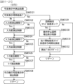
図6は、特別図柄プロセス処理として、図5に示すステップS25にて実行される処理の一例を示すフローチャートである。この特別図柄プロセス処理において、CPU103は、まず、始動入賞判定処理を実行する(ステップS101)。
FIG. 6 is a flow chart showing an example of the process executed in step S25 shown in FIG. 5 as the special symbol process process. In this special symbol process process, the
始動入賞判定処理では、始動入賞の発生を検出し、RAM102の所定領域に保留情報を格納し保留記憶数を更新する処理が実行される。始動入賞が発生すると、表示結果(大当り種別を含む)や変動パターンを決定するための乱数値が抽出され、保留情報として記憶される。また、抽出した乱数値に基づいて、表示結果や変動パターンを先読判定する処理が実行されてもよい。保留情報や保留記憶数を記憶した後には、演出制御基板12に始動入賞の発生、保留記憶数、先読判定等の判定結果を指定するための演出制御コマンドを送信するための送信設定が行われる。こうして送信設定された始動入賞時の演出制御コマンドは、例えば特別図柄プロセス処理が終了した後、図5に示すステップS27のコマンド制御処理が実行されることなどにより、主基板11から演出制御基板12に対して伝送される。
In the starting prize determination process, the process of detecting the occurrence of the starting prize, storing pending information in a predetermined area of the
ステップS101にて始動入賞判定処理を実行した後、CPU103は、RAM102に設けられた特図プロセスフラグの値に応じて、ステップS110~S120の処理のいずれかを選択して実行する。なお、特別図柄プロセス処理の各処理(ステップS110~S120)では、各処理に対応した演出制御コマンドを演出制御基板12に送信するための送信設定が行われる。
After executing the starting prize determination process in step S101, the
ステップS110の特別図柄通常処理は、特図プロセスフラグの値が“0”(初期値)のときに実行される。この特別図柄通常処理では、保留情報の有無などに基づいて、第1特図ゲームまたは第2特図ゲームを開始するか否かの判定が行われる。また、特別図柄通常処理では、表示結果決定用の乱数値に基づき、特別図柄や飾り図柄の表示結果を「大当り」または「小当り」とするか否かや「大当り」とする場合の大当り種別を、その表示結果が導出表示される以前に決定(事前決定)する。さらに、特別図柄通常処理では、決定された表示結果に対応して、特図ゲームにおいて停止表示させる確定特別図柄(大当り図柄や小当り図柄、ハズレ図柄のいずれか)が設定される。その後、特図プロセスフラグの値が“1”に更新され、特別図柄通常処理は終了する。なお、第2特図を用いた特図ゲームが第1特図を用いた特図ゲームよりも優先して実行されるようにしてもよい(特図2優先消化ともいう)。また、第1始動入賞口および第2始動入賞口への遊技球の入賞順序を記憶し、入賞順に特図ゲームの開始条件を成立させるようにしてもよい(入賞順消化ともいう)。 The special symbol normal process of step S110 is executed when the value of the special symbol process flag is "0" (initial value). In this special symbol normal process, it is determined whether or not to start the first special symbol game or the second special symbol game based on the presence or absence of pending information. In addition, in the special symbol normal processing, based on the random number value for determining the display result, whether or not the display result of the special symbol or the decorative symbol is a "big hit" or "small hit", and the type of the big hit in the case of "big hit". is determined (predetermined) before the display result is derived and displayed. Furthermore, in the special symbol normal process, a fixed special symbol (any one of a big hit symbol, a small winning symbol, or a losing symbol) to be stopped and displayed in the special symbol game is set according to the determined display result. After that, the value of the special figure process flag is updated to "1", and the special symbol normal process ends. In addition, the special figure game using the second special figure may be executed with priority over the special figure game using the first special figure (also called special figure 2 priority digestion). Also, the winning order of the game balls to the first start winning opening and the second starting winning opening may be stored, and the start condition of the special game may be established in the order of winning (also called winning order).
乱数値に基づき各種の決定を行う場合には、ROM101に格納されている各種のテーブル(乱数値と比較される決定値が決定結果に割り当てられているテーブル)が参照される。主基板11における他の決定、演出制御基板12における各種の決定についても同じである。演出制御基板12においては、各種のテーブルがROM121に格納されている。
When making various decisions based on random numbers, various tables stored in the ROM 101 (tables in which decision values to be compared with random numbers are assigned to decision results) are referred to. Other decisions on the
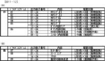
ステップS111の変動パターン設定処理は、特図プロセスフラグの値が“1”のときに実行される。この変動パターン設定処理には、表示結果を「大当り」または「小当り」とするか否かの事前決定結果等に基づき、変動パターン決定用の乱数値を用いて変動パターンを複数種類のいずれかに決定する処理などが含まれている。変動パターン設定処理では、変動パターンを決定したときに、特図プロセスフラグの値が“2”に更新され、変動パターン設定処理は終了する。 The variation pattern setting process of step S111 is executed when the value of the special figure process flag is "1". In this variation pattern setting process, one of a plurality of variation patterns is selected using random numbers for determining the variation pattern based on the result of pre-determination as to whether the display result is a "big hit" or a "small hit." including the process of determining In the variation pattern setting process, when the variation pattern is determined, the value of the special figure process flag is updated to "2", and the variation pattern setting process ends.
変動パターンは、特図ゲームの実行時間(特図変動時間)(飾り図柄の可変表示の実行時間でもある)や、飾り図柄の可変表示の態様(リーチの有無等)、飾り図柄の可変表示中の演出内容(リーチ演出の種類等)を指定するものであり、可変表示パターンとも呼ばれる。 The variation pattern is the execution time of the special game (special figure fluctuation time) (also the execution time of the variable display of the decorative pattern), the form of variable display of the decorative pattern (whether or not there is reach, etc.), and the variable display of the decorative pattern It designates the content of the production (type of reach production, etc.), and is also called a variable display pattern.
ステップS112の特別図柄変動処理は、特図プロセスフラグの値が“2”のときに実行される。この特別図柄変動処理には、第1特別図柄表示装置4Aや第2特別図柄表示装置4Bにおいて特別図柄を変動させるための設定を行う処理や、その特別図柄が変動を開始してからの経過時間を計測する処理などが含まれている。また、計測された経過時間が変動パターンに対応する特図変動時間に達したか否かの判定も行われる。そして、特別図柄の変動を開始してからの経過時間が特図変動時間に達したときには、特図プロセスフラグの値が“3”に更新され、特別図柄変動処理は終了する。
The special symbol variation process of step S112 is executed when the value of the special symbol process flag is "2". This special symbol variation processing includes a process of setting for varying the special symbols in the first special
ステップS113の特別図柄停止処理は、特図プロセスフラグの値が“3”のときに実行される。この特別図柄停止処理には、第1特別図柄表示装置4Aや第2特別図柄表示装置4Bにて特別図柄の変動を停止させ、特別図柄の表示結果となる確定特別図柄を停止表示(導出)させるための設定を行う処理が含まれている。そして、表示結果が「大当り」である場合には特図プロセスフラグの値が“4”に更新される。その一方で、大当りフラグがオフであり、表示結果が「小当り」である場合には、特図プロセスフラグの値が“8”に更新される。また、表示結果が「ハズレ」である場合には、特図プロセスフラグの値が“0”に更新される。表示結果が「小当り」または「ハズレ」である場合、時短状態や確変状態に制御されているときであって、回数切りの終了成立する場合には、遊技状態も更新される。特図プロセスフラグの値が更新されると、特別図柄停止処理は終了する。
The special symbol stop processing of step S113 is executed when the value of the special symbol process flag is "3". In this special symbol stop processing, the first special
ステップS114の大当り開放前処理は、特図プロセスフラグの値が“4”のときに実行される。この大当り開放前処理には、表示結果が「大当り」となったことなどに基づき、大当り遊技状態においてラウンドの実行を開始して大入賞口を開放状態とするための設定を行う処理などが含まれている。大入賞口を開放状態とするときには、大入賞口扉用のソレノイド82に対してソレノイド駆動信号を供給する処理が実行される。このときには、例えば大当り種別がいずれであるかに対応して、大入賞口を開放状態とする開放上限期間や、ラウンドの上限実行回数を設定する。これらの設定が終了すると、特図プロセスフラグの値が“5”に更新され、大当り開放前処理は終了する。 The jackpot opening preprocessing of step S114 is executed when the value of the special figure process flag is "4". This jackpot opening pre-processing includes processing for making settings for starting the execution of the round in the jackpot game state and opening the jackpot, based on the fact that the display result is "jackpot". is When opening the big winning opening, a process of supplying a solenoid drive signal to the solenoid 82 for the big winning opening door is executed. At this time, for example, an upper limit opening period for opening the big winning opening and an upper limit execution number of rounds are set according to the type of the jackpot. When these settings are finished, the value of the special figure process flag is updated to "5", and the big hit opening pretreatment is finished.
ステップS115の大当り開放中処理は、特図プロセスフラグの値が“5”のときに実行される。この大当り開放中処理には、大入賞口を開放状態としてからの経過時間を計測する処理や、その計測した経過時間やカウントスイッチ23によって検出された遊技球の個数などに基づいて、大入賞口を開放状態から閉鎖状態に戻すタイミングとなったか否かを判定する処理などが含まれている。そして、大入賞口を閉鎖状態に戻すときには、大入賞口扉用のソレノイド82に対するソレノイド駆動信号の供給を停止させる処理などを実行した後、特図プロセスフラグの値が“6”に更新し、大当り開放中処理を終了する。
The process during jackpot opening of step S115 is performed when the value of a special figure process flag is "5". In this process during the opening of the big win, there is a process of measuring the elapsed time from opening the big winning hole, and based on the measured elapsed time and the number of game balls detected by the
ステップS116の大当り開放後処理は、特図プロセスフラグの値が“6”のときに実行される。この大当り開放後処理には、大入賞口を開放状態とするラウンドの実行回数が設定された上限実行回数に達したか否かを判定する処理や、上限実行回数に達した場合に大当り遊技状態を終了させるための設定を行う処理などが含まれている。そして、ラウンドの実行回数が上限実行回数に達していないときには、特図プロセスフラグの値が“5”に更新される一方、ラウンドの実行回数が上限実行回数に達したときには、特図プロセスフラグの値が“7”に更新される。特図プロセスフラグの値が更新されると、大当り解放後処理は終了する。 The jackpot opening post-processing of step S116 is executed when the value of the special figure process flag is "6". This jackpot opening post-processing includes a process of determining whether or not the number of executions of a round in which the jackpot is opened has reached a set upper limit execution number, and a jackpot game state when the number of executions reaches the upper limit execution number. It includes processing to make settings for terminating . Then, when the number of executions of the round has not reached the upper limit number of executions, the value of the special process flag is updated to "5", while when the number of executions of the round reaches the upper limit number of executions, the special process flag The value is updated to "7". When the value of the special figure process flag is updated, the jackpot release post-processing ends.
ステップS117の大当り終了処理は、特図プロセスフラグの値が“7”のときに実行される。この大当り終了処理には、大当り遊技状態の終了を報知する演出動作としてのエンディング演出が実行される期間に対応した待ち時間が経過するまで待機する処理や、大当り遊技状態の終了に対応して確変制御や時短制御を開始するための各種の設定を行う処理などが含まれている。こうした設定が行われたときには、特図プロセスフラグの値が“0”に更新され、大当り終了処理は終了する。 The jackpot end processing of step S117 is executed when the value of the special figure process flag is "7". This jackpot end processing includes a process of waiting until the waiting time corresponding to the period in which the ending production as a production operation for informing the end of the jackpot game state has passed, and a probability change corresponding to the end of the jackpot game state. It includes processing for performing various settings for starting control and time saving control. When such setting is performed, the value of the special figure process flag is updated to "0", and the jackpot ending process ends.
ステップS118の小当り開放前処理は、特図プロセスフラグの値が“8”のときに実行される。この小当り開放前処理には、表示結果が「小当り」となったことに基づき、小当り遊技状態において大入賞口を開放状態とするための設定を行う処理などが含まれている。このときには、特図プロセスフラグの値が“9”に更新され、小当り開放前処理は終了する。 Small hit opening pretreatment of step S118 is executed when the value of the special figure process flag is "8". This small hit opening pre-processing includes a process of setting to open the big winning opening in the small win game state based on the display result being "small win". At this time, the value of the special figure process flag is updated to "9", and the small hit opening preprocessing ends.
ステップS119の小当り開放中処理は、特図プロセスフラグの値が“9”のときに実行される。この小当り開放中処理には、大入賞口を開放状態としてからの経過時間を計測する処理や、その計測した経過時間などに基づいて、大入賞口を開放状態から閉鎖状態に戻すタイミングとなったか否かを判定する処理などが含まれている。大入賞口を閉鎖状態に戻して小当り遊技状態の終了タイミングとなったときには、特図プロセスフラグの値が“10”に更新され、小当り開放中処理は終了する。 The process during the small hit opening of step S119 is performed when the value of the special figure process flag is "9". In this process during opening of the small prize, there is a process of measuring the elapsed time from opening the big winning opening, and the timing of returning the big winning opening from the open state to the closed state based on the measured elapsed time. It includes processing for determining whether or not When the big winning opening is returned to the closed state and the end timing of the small winning game state comes, the value of the special figure process flag is updated to "10", and the small winning open processing is ended.
ステップS120の小当り終了処理は、特図プロセスフラグの値が“10”のときに実行される。この小当り終了処理には、小当り遊技状態の終了を報知する演出動作が実行される期間に対応した待ち時間が経過するまで待機する処理などが含まれている。ここで、小当り遊技状態が終了するときには、小当り遊技状態となる以前のパチンコ遊技機1における遊技状態を継続させる。小当り遊技状態の終了時における待ち時間が経過したときには、特図プロセスフラグの値が“0”に更新され、小当り終了処理は終了する。
Small hit end processing of step S120 is executed when the value of the special figure process flag is "10". This small-hit end processing includes a process of waiting until the waiting time corresponding to the period during which the effect operation for informing the end of the small-hit game state is executed elapses. Here, when the small winning game state ends, the game state in the
パチンコ遊技機1は、設定値に応じて大当りの当選確率や出玉率が変わる構成とされている。例えば、特別図柄プロセス処理の特別図柄通常処理において、設定値に応じた表示結果判定テーブル(当選確率)を用いることにより、大当りの当選確率や出玉率が変わるようになっている。例えば設定値は1~6の6段階からなり、6が最も大当りの当選確率が高く、6、5、4、3、2、1の順に値が小さくなるほど大当りの当選確率が低くなる。この例において、設定値として6が設定されている場合には遊技者にとって最も有利度が高く、6、5、4、3、2、1の順に値が小さくなるほど有利度が段階的に低くなる。設定値に応じて大当りの当選確率が変われば、出玉率も設定値に応じて変わってもよい。大当りの当選確率は設定値にかかわらず一定であるのに対し、大当り遊技状態におけるラウンド数が設定値に応じて変わってもよい。パチンコ遊技機1は、遊技者にとっての有利度が異なる複数の設定値のうちいずれかを設定可能に構成されていればよい。パチンコ遊技機1において設定されている設定値は、主基板11の側から演出制御基板12の側へ設定値指定コマンドが送信されることにより通知される。
The
図7は、表示結果判定テーブルの構成例を示している。図7(A)は、変動特図が第1特図である場合に用いられる第1特図用表示結果判定テーブルの構成例を示し、図7(B)は、変動特図が第2特図である場合に用いられる第2特図用表示結果判定テーブルの構成例を示している。表示結果判定テーブルは、ROM101に記憶されているデータの集まりである。表示結果判定テーブルでは、設定値に応じて、乱数値MR1と比較される当り判定値が特別図柄の可変表示結果である特図表示結果に割り当てられている。乱数値MR1は、表示結果決定用の乱数値であり、0~65535の範囲でランダムに値が更新される。表示結果判定テーブルとして、第1特図と第2特図とで共通の表示結果判定テーブルを用いるようにしてもよい。
FIG. 7 shows a configuration example of a display result determination table. FIG. 7(A) shows a configuration example of the first special figure display result determination table used when the fluctuation special figure is the first special figure, and FIG. It shows a configuration example of the display result determination table for the second special figure used when it is a figure. A display result determination table is a collection of data stored in the
表示結果判定テーブルにおいては、遊技状態が確変状態(高確状態)であるときに、通常状態または時短状態(低確状態)であるときよりも多くの判定値が、「大当り」の特図表示結果に割り当てられている。これにより、パチンコ遊技機1において確変制御が行われる確変状態といった高確状態であるときには、通常状態または時短状態といった低確状態であるときに比べて、大当り遊技状態に制御すると決定される確率が高くなる。
In the display result determination table, when the gaming state is a probability variable state (high probability state), more judgment values than when it is a normal state or a time saving state (low probability state), "big hit" special figure display assigned to the result. Thereby, when it is a high probability state such as a probability variable state in which probability variable control is performed in the
第1特図用表示結果判定テーブルにおいては、遊技状態や設定値にかかわらず、特図表示結果を「小当り」として小当り遊技状態に制御すると決定される確率が同一値となるように判定値が割り当てられている。第2特図用表示結果判定テーブルにおいては、遊技状態や設定値にかかわらず、特図表示結果を「小当り」として小当り遊技状態に制御すると決定される確率が第1特図用表示結果判定テーブルとは異なる同一値となるように判定値が割り当てられている。なお、設定値に応じて特図表示結果を「小当り」として小当り遊技状態に制御すると決定される確率を異ならせてもよい。変動特図にかかわらず特図表示結果を「小当り」として小当り遊技状態に制御すると決定される確率を同一確率としてもよい。 In the first special figure display result determination table, regardless of the game state or set value, the probability of determining that the special figure display result is "small win" and controlled to the small win game state is determined to be the same value. has been assigned a value. In the second special figure display result determination table, regardless of the game state or setting value, the probability that the special figure display result is controlled to the small hit game state as "small hit" is the first special figure display result Determination values are assigned so as to be the same values different from those in the determination table. In addition, depending on the set value, the probability that the special figure display result is controlled to the small hit game state as the "small hit" may be changed. The probability that the special figure display result is controlled to the small winning game state as "small hit" regardless of the variation special figure may be the same probability.
第1特図用表示結果判定テーブルおよび第2特図用表示結果判定テーブルでは、遊技状態が通常状態または時短状態の場合に、当り判定値のうち1020から1237までの範囲が、設定値にかかわらず大当りを判定するための大当り判定値の共通数値範囲に設定されている。設定値が1の場合は、1020から1237までが「大当り」に割り当てられ、大当りを判定するための大当り判定値の共通数値範囲のみが設定されている一方で、設定値2~設定値6の場合は、大当り判定値の共通数値範囲から連続するように、1238から各設定値に応じた数値範囲が大当り判定値の非共通数値範囲に設定されている。
In the display result determination table for the first special figure and the display result determination table for the second special figure, when the game state is the normal state or the time saving state, the range from 1020 to 1237 of the hit judgment value is set regardless of the set value It is set to the common numerical range of the jackpot determination value for judging the jackpot. When the set value is 1, 1020 to 1237 are assigned to the "jackpot", and only the common numerical range of the jackpot determination value for judging the jackpot is set, while the
第1特図用表示結果判定テーブルおよび第2特図用表示結果判定テーブルでは、遊技状態が確変状態の場合に、当り判定値のうち1020から1346までの範囲が、設定値にかかわらず大当りを判定するための大当り判定値の共通数値範囲に設定されている。設定値が1の場合は、1020から1346までが「大当り」に割り当てられることで、大当りを判定するための大当り判定値の共通数値範囲のみが設定され、その一方で、設定値2~設定値6の場合は、大当り判定値の共通数値範囲から連続するように、1346から各設定値に応じた数値範囲が大当り判定値の非共通数値範囲に設定される。
In the display result determination table for the first special figure and the display result determination table for the second special figure, when the game state is the variable probability state, the range from 1020 to 1346 of the hit determination values is a big hit regardless of the set value. It is set to the common numerical range of the jackpot judgment value for judging. When the set value is 1, by assigning 1020 to 1346 to the "jackpot", only the common numerical range of the jackpot determination value for judging the jackpot is set, while the
第1特図用表示結果判定テーブルでは、遊技状態が通常状態または時短状態である場合に、当り判定値のうち32767から33094までの範囲が、設定値にかかわらず小当りを判定するための小当り判定値の共通数値範囲に設定されている。小当り判定値は、設定値が1~6のいずれである場合にも、大当り判定値の共通数値範囲および非共通数値範囲とは異なる数値範囲に設定されている。これにより、小当り判定値の数値範囲が各設定値に応じて変化する大当り判定値の範囲に重複することが防止されている。 In the first special figure display result determination table, when the gaming state is the normal state or the time saving state, the range from 32767 to 33094 of the hit determination values is a small value for determining a small hit regardless of the set value. It is set in the common numerical range of the hit judgment value. The small-hit determination value is set to a numerical range different from the common numerical range and non-common numerical range of the big-hit determination value, regardless of whether the set value is 1-6. This prevents the numerical range of the small-hit determination value from overlapping with the range of the big-hit determination value that varies according to each set value.
第1特図用表示結果判定テーブルでは、遊技状態が確変状態である場合に、遊技状態が通常状態または時短状態である場合と同じく、当り判定値のうち32767から33094までの範囲が、設定値にかかわらず小当りを判定するための小当り判定値の共通数値範囲に設定されている。小当り判定値は、設定値が1~6のいずれである場合にも、大当り判定値の共通数値範囲および非共通数値範囲とは異なる数値範囲に設定されている。これにより、小当り判定値の数値範囲が各設定値に応じて変化する大当り判定値の範囲に重複することが防止されている。 In the first special figure display result determination table, when the gaming state is a variable probability state, the range from 32767 to 33094 in the hit determination value is the set value Regardless, it is set to a common numerical range of the small hit determination value for judging the small hit. The small-hit determination value is set to a numerical range different from the common numerical range and non-common numerical range of the big-hit determination value, regardless of whether the set value is 1-6. This prevents the numerical range of the small-hit determination value from overlapping with the range of the big-hit determination value that varies according to each set value.
第2特図用表示結果判定テーブルでは、遊技状態が通常状態または時短状態である場合に、当り判定値のうち32767から33421までの範囲が、設定値にかかわらず小当りを判定するための小当り判定値の共通数値範囲に設定されている。小当り判定値は、設定値が1~6のいずれである場合にも、大当り判定値の共通数値範囲および非共通数値範囲とは異なる数値範囲に設定されている。これにより、小当り判定値の数値範囲が各設定値に応じて変化する大当り判定値の範囲に重複することが防止されている。 In the second special figure display result determination table, when the gaming state is the normal state or the time saving state, the range from 32767 to 33421 of the hit determination values is a small value for determining a small hit regardless of the set value. It is set in the common numerical range of the hit judgment value. The small-hit determination value is set to a numerical range different from the common numerical range and non-common numerical range of the big-hit determination value, regardless of whether the set value is 1-6. This prevents the numerical range of the small-hit determination value from overlapping the range of the big-hit determination value that varies according to each set value.
第2特図用表示結果判定テーブルでは、遊技状態が確変状態である場合に、遊技状態が通常状態または時短状態である場合と同じく、当り判定値のうち32767から33421までの範囲が、設定値にかかわらず小当りを判定するための小当り判定値の共通数値範囲に設定されている。小当り判定値は、設定値が1~6のいずれである場合にも、大当り判定値の共通数値範囲および非共通数値範囲とは異なる数値範囲に設定されている。これにより、小当り判定値の数値範囲が各設定値に応じて変化する大当り判定値の範囲に重複することが防止されている。 In the second special figure display result determination table, when the gaming state is a variable probability state, the range from 32767 to 33421 of the hit determination value is the set value Regardless, it is set to a common numerical range of the small hit determination value for judging the small hit. The small-hit determination value is set to a numerical range different from the common numerical range and non-common numerical range of the big-hit determination value, regardless of whether the set value is 1-6. This prevents the numerical range of the small-hit determination value from overlapping with the range of the big-hit determination value that varies according to each set value.
パチンコ遊技機1に設定可能な設定値は、5個以下や7個以上であってもよい。パチンコ遊技機1に設定される設定値が小さいほど遊技者にとって有利となるようにしてもよい。パチンコ遊技機1に設定される設定値に応じて遊技性が変化するようにしてもよい。例えば、パチンコ遊技機1に設定される設定値が1である場合は、通常状態での大当り確率が1/320、確変状態が65%の割合でループする遊技性(いわゆる確変ループタイプ)とし、パチンコ遊技機1に設定されている設定値が2である場合は、通常状態での大当り確率が1/200、大当り遊技中に遊技球が、特別可変入賞球装置7の内部に設けられた所定スイッチを通過することに基づいて大当り遊技終了後の遊技状態を確変状態に制御する一方で、変動特図に応じて大当り遊技中に遊技球が所定スイッチを通過する割合が異なる遊技性(いわゆるV確変タイプ)とし、パチンコ遊技機1に設定されている設定値が3である場合は、大当り確率が1/320で小当り確率が1/50であり、高ベース中(時短制御中)に遊技球が特別可変入賞球装置7の内部に設けられた所定スイッチを通過することに基づいて大当り遊技状態に制御する遊技性(いわゆる1種2種混合タイプ)としてもよい。パチンコ遊技機1に設定されている設定値が1~3のいずれかである場合は遊技性が同一であるが、これら設定値が1~3のいずれかである場合よりも大当り確率や小当り確率が高い一方で大当り遊技中に獲得可能な賞球数が少ない設定(例えば、パチンコ遊技機1に設定されている設定値が4~6のいずれかである場合)を設けてもよい。設定値に応じて遊技性を変化させる場合は、共通のスイッチを異なる用途に使用してもよい。具体的には、設定値が1~3の場合は、特別可変入賞球装置7内に設けられた所定スイッチを演出用スイッチ(遊技球が所定領域を通過する毎に所定の演出を実行するためのスイッチ)として使用し、設定値が4~6の場合は、所定スイッチを遊技用スイッチ(遊技球が所定スイッチを通過したことに基づいて遊技状態を確変状態や大当り遊技状態に制御するためのスイッチ)として使用してもよい。
The set values that can be set in the
大当り種別は、大当り種別判定テーブルにおける判定値の割当てに基づいて、設定値に応じて異なる割合で決定されてもよい。あるいは、大当り種別は、設定値にかかわらず共通の割合で決定されてもよい。変動パターンは、変動パターン判定テーブルにおける判定値の割当てに基づいて、設定値に応じて異なる割合で決定されてもよい。あるいは、変動パターンは、設定値にかかわらず共通の割合で決定されてもよい。設定値に応じてノーマルリーチやスーパーリーチの実行割合が異なることで、ノーマルリーチやスーパーリーチが実行される頻度により設定値が示唆されてもよい。あるいは、設定値にかかわらずノーマルリーチやスーパーリーチの実行割合は共通であってもよい。その他、設定値に応じて、異なる割合で任意の設定示唆演出を実行可能としたものであってもよい。 The jackpot type may be determined at different ratios depending on the set value based on the assignment of the determination value in the jackpot type determination table. Alternatively, the jackpot type may be determined at a common rate regardless of the set value. The variation pattern may be determined at different ratios according to the set values based on the allocation of the determination values in the variation pattern determination table. Alternatively, the variation pattern may be determined with a common ratio regardless of the set value. A set value may be suggested by the frequency with which normal reach and super reach are performed by having the execution ratio of normal reach and super reach differ according to a set value. Alternatively, regardless of the setting value, the execution ratio of normal reach and super reach may be common. In addition, it may be possible to execute arbitrary setting suggestion effects at different ratios according to the set values.
(演出制御基板12の主要な動作)
次に、演出制御基板12における主要な動作を説明する。演出制御基板12では、電源基板等から電源電圧の供給を受けると、演出制御用CPU120が起動して、図8のフローチャートに示すような演出制御メイン処理を実行する。図8に示す演出制御メイン処理を開始すると、演出制御用CPU120は、まず、所定の初期化処理を実行して(ステップS71)、RAM122のクリアや各種初期値の設定、また演出制御基板12に搭載されたCTC(カウンタ/タイマ回路)のレジスタ設定等を行う。また、初期動作制御処理を実行する(ステップS72)。初期動作制御処理では、可動体32を駆動して初期位置に戻す制御、所定の動作確認を行う制御といった可動体32の初期動作を行う制御が実行される。
(Major operations of production control board 12)
Next, main operations in the
その後、タイマ割込みフラグがオンとなっているか否かの判定を行う(ステップS73)。タイマ割込みフラグは、例えばCTCのレジスタ設定に基づき、所定時間(例えば2ミリ秒)が経過するごとにオン状態にセットされる。このとき、タイマ割込みフラグがオフであれば(ステップS73;No)、ステップS73の処理を繰り返し実行して待機する。 After that, it is determined whether or not the timer interrupt flag is turned on (step S73). The timer interrupt flag is set to ON every time a predetermined time (for example, 2 milliseconds) elapses based on, for example, the CTC register setting. At this time, if the timer interrupt flag is off (step S73; No), the process of step S73 is repeated and waits.
また、演出制御基板12の側では、所定時間が経過するごとに発生するタイマ割込みとは別に、主基板11からの演出制御コマンドを受信するための割込みが発生する。この割込みは、例えば主基板11からの演出制御INT信号がオン状態となることにより発生する割込みである。演出制御INT信号がオン状態となることによる割込みが発生すると、演出制御用CPU120は、自動的に割込み禁止に設定するが、自動的に割込み禁止状態にならないCPUを用いている場合には、割込み禁止命令(DI命令)を発行することが望ましい。演出制御用CPU120は、演出制御INT信号がオン状態となることによる割込みに対応して、例えば所定のコマンド受信割込み処理を実行する。このコマンド受信割込み処理では、I/O125に含まれる入力ポートのうちで、中継基板15を介して主基板11から送信された制御信号を受信する所定の入力ポートより、演出制御コマンドを取り込む。このとき取り込まれた演出制御コマンドは、例えばRAM122に設けられた演出制御コマンド受信用バッファに格納する。その後、演出制御用CPU120は、割込み許可に設定してから、コマンド受信割込み処理を終了する。
Also, on the side of the
ステップS73にてタイマ割込みフラグがオンである場合には(ステップS73;Yes)、タイマ割込みフラグをクリアしてオフ状態にするとともに(ステップS74)、コマンド解析処理を実行する(ステップS75)。コマンド解析処理では、例えば主基板11の遊技制御用マイクロコンピュータ100から送信されて演出制御コマンド受信用バッファに格納されている各種の演出制御コマンドを読み出した後に、その読み出された演出制御コマンドに対応した設定や制御などが行われる。例えば、どの演出制御コマンドを受信したかや演出制御コマンドが特定する内容等を演出制御プロセス処理等で確認できるように、読み出された演出制御コマンドをRAM122の所定領域に格納したり、RAM122に設けられた受信フラグをオンしたりする。また、演出制御コマンドが遊技状態を特定する場合、遊技状態に応じた背景の表示を表示制御部123に指示してもよい。
If the timer interrupt flag is ON at step S73 (step S73; Yes), the timer interrupt flag is cleared to be turned off (step S74), and command analysis processing is executed (step S75). In the command analysis process, for example, after reading various effect control commands that are transmitted from the
ステップS75にてコマンド解析処理を実行した後には、演出制御プロセス処理を実行する(ステップS76)。演出制御プロセス処理では、例えば画像表示装置5の表示領域における演出画像の表示動作、スピーカ8L、8Rからの音声出力動作、遊技効果ランプ9および装飾用LEDといった装飾発光体における点灯動作、可動体32の駆動動作といった、各種の演出装置を動作させる制御が行われる。また、各種の演出装置を用いた演出動作の制御内容について、主基板11から送信された演出制御コマンド等に応じた判定や決定、設定などが行われる。
After executing the command analysis process in step S75, the effect control process process is executed (step S76). In the effect control process processing, for example, the display operation of the effect image in the display area of the
ステップS76の演出制御プロセス処理に続いて、演出用乱数更新処理が実行され(ステップS77)、演出制御基板12の側で用いられる演出用乱数の少なくとも一部がソフトウェアにより更新される。その後、ステップS73の処理に戻る。ステップS73の処理に戻る前に、他の処理が実行されてもよい。
Random number update processing for production|presentation is performed following the production|presentation control process processing of step S76 (step S77), and at least one part of the random number for production|presentation used by the production|
図9は、演出制御プロセス処理として、図8のステップS76にて実行される処理の一例を示すフローチャートである。図9に示す演出制御プロセス処理において、演出制御用CPU120は、まず、先読予告設定処理を実行する(ステップS161)。先読予告設定処理では、例えば、主基板11から送信された始動入賞時の演出制御コマンドに基づいて、先読予告演出を実行するための判定や決定、設定などが行われる。また、当該演出制御コマンドから特定される保留記憶数に基づき保留表示を表示するための処理が実行される。
FIG. 9 is a flow chart showing an example of processing executed in step S76 of FIG. 8 as the effect control process processing. In the effect control process shown in FIG. 9, the
ステップS161の処理を実行した後、演出制御用CPU120は、例えばRAM122に設けられた演出プロセスフラグの値に応じて、以下のようなステップS170~S177の処理のいずれかを選択して実行する。
After executing the process of step S161, the
ステップS170の可変表示開始待ち処理は、演出プロセスフラグの値が“0”(初期値)のときに実行される処理である。この可変表示開始待ち処理は、主基板11から可変表示の開始を指定するコマンドなどを受信したか否かに基づき、画像表示装置5における飾り図柄の可変表示を開始するか否かを判定する処理などを含んでいる。画像表示装置5における飾り図柄の可変表示を開始すると判定された場合、演出プロセスフラグの値を“1”に更新し、可変表示開始待ち処理を終了する。
The process of waiting for the start of variable display in step S170 is a process executed when the value of the effect process flag is "0" (initial value). This variable display start waiting process is a process of determining whether or not to start variable display of decorative patterns on the
ステップS171の可変表示開始設定処理は、演出プロセスフラグの値が“1”のときに実行される処理である。この可変表示開始設定処理では、演出制御コマンドにより特定される表示結果や変動パターンに基づいて、飾り図柄の可変表示の表示結果(確定飾り図柄)、飾り図柄の可変表示の態様、リーチ演出や各種予告演出などの各種演出の実行の有無やその態様や実行開始タイミングなどを決定する。そして、その決定結果等を反映した演出制御パターン(表示制御部123に演出の実行を指示するための制御データの集まり)を設定する。その後、設定した演出制御パターンに基づいて、飾り図柄の可変表示の実行開始を表示制御部123に指示し、演出プロセスフラグの値を“2”に更新し、可変表示開始設定処理を終了する。表示制御部123は、飾り図柄の可変表示の実行開始の指示により、画像表示装置5において、飾り図柄の可変表示を開始させる。
The variable display start setting process in step S171 is a process executed when the value of the effect process flag is "1". In this variable display start setting process, based on the display result and variation pattern specified by the effect control command, the display result of the variable display of the decorative pattern (determined decorative pattern), the form of the variable display of the decorative pattern, the ready-to-win effect, and various other Whether or not to execute various effects such as advance notice effects, its mode, execution start timing, etc. are determined. Then, an effect control pattern (collection of control data for instructing the
ステップS172の可変表示中演出処理は、演出プロセスフラグの値が“2”のときに実行される処理である。この可変表示中演出処理において、演出制御用CPU120は、表示制御部123を指示することで、ステップS171にて設定された演出制御パターンに基づく演出画像を画像表示装置5の表示画面に表示させることや、可動体32を駆動させること、音声制御基板13に対する指令(効果音信号)の出力によりスピーカ8L、8Rから音声や効果音を出力させること、ランプ制御基板14に対する指令(電飾信号)の出力により遊技効果ランプ9や装飾用LEDを点灯/消灯/点滅させることといった、飾り図柄の可変表示中における各種の演出制御を実行する。こうした演出制御を行った後、例えば演出制御パターンから飾り図柄の可変表示終了を示す終了コードが読み出されたこと、あるいは、主基板11から確定飾り図柄を停止表示させることを指定するコマンドを受信したことなどに対応して、飾り図柄の表示結果となる確定飾り図柄を停止表示させる。確定飾り図柄を停止表示したときには、演出プロセスフラグの値が“3”に更新され、可変表示中演出処理は終了する。
The effect process during variable display in step S172 is a process executed when the value of the effect process flag is "2". In this variable display effect processing, the
ステップS173の特図当り待ち処理は、演出プロセスフラグの値が“3”のときに実行される処理である。この特図当り待ち処理において、演出制御用CPU120は、主基板11から大当り遊技状態または小当り遊技状態を開始することを指定する演出制御コマンドの受信があったか否かを判定する。そして、大当り遊技状態または小当り遊技状態を開始することを指定する演出制御コマンドを受信したきに、そのコマンドが大当り遊技状態の開始を指定するものであれば、演出プロセスフラグの値を“6”に更新する。これに対して、そのコマンドが小当り遊技状態の開始を指定するものであれば、演出プロセスフラグの値を小当り中演出処理に対応した値である“4”に更新する。また、大当り遊技状態または小当り遊技状態を開始することを指定するコマンドを受信せずに、当該コマンドの受信待ち時間が経過したときには、特図ゲームにおける表示結果が「ハズレ」であったと判定して、演出プロセスフラグの値を初期値である“0”に更新する。演出プロセスフラグの値を更新すると、特図当り待ち処理を終了する。
The special figure per waiting process of step S173 is a process executed when the value of the production process flag is "3". In this special figure waiting process, the
ステップS174の小当り中演出処理は、演出プロセスフラグの値が“4”のときに実行される処理である。この小当り中演出処理において、演出制御用CPU120は、例えば小当り遊技状態における演出内容に対応した演出制御パターン等を設定し、その設定内容に基づく小当り遊技状態における各種の演出制御を実行する。また、小当り中演出処理では、例えば主基板11から小当り遊技状態を終了することを指定するコマンドを受信したことに対応して、演出プロセスフラグの値を小当り終了演出に対応した値である“5”に更新し、小当り中演出処理を終了する。
The production process during a small hit in step S174 is a process executed when the value of the production process flag is "4". In this small-hit mid-performance process, the
ステップS175の小当り終了演出処理は、演出プロセスフラグの値が“5”のときに実行される処理である。この小当り終了演出処理において、演出制御用CPU120は、例えば小当り遊技状態の終了などに対応した演出制御パターン等を設定し、その設定内容に基づく小当り遊技状態の終了時における各種の演出制御を実行する。その後、演出プロセスフラグの値を初期値である“0”に更新し、小当り終了演出処理を終了する。
The small hit end production process of step S175 is a process executed when the value of the production process flag is "5". In this small hit end effect processing, the
ステップS176の大当り中演出処理は、演出プロセスフラグの値が“6”のときに実行される処理である。この大当り中演出処理において、演出制御用CPU120は、例えば大当り遊技状態における演出内容に対応した演出制御パターン等を設定し、その設定内容に基づく大当り遊技状態における各種の演出制御を実行する。また、大当り中演出処理では、例えば主基板11から大当り遊技状態を終了することを指定するコマンドを受信したことに対応して、演出プロセスフラグの値をエンディング演出処理に対応した値である“7”に更新し、大当り中演出処理を終了する。
The effect process during the big hit in step S176 is a process executed when the value of the effect process flag is "6". In this big-hit production process, the
ステップS177のエンディング演出処理は、演出プロセスフラグの値が“7”のときに実行される処理である。このエンディング演出処理において、演出制御用CPU120は、例えば大当り遊技状態の終了などに対応した演出制御パターン等を設定し、その設定内容に基づく大当り遊技状態の終了時におけるエンディング演出の各種の演出制御を実行する。その後、演出プロセスフラグの値を初期値である“0”に更新し、エンディング演出処理を終了する。
The ending effect process of step S177 is a process executed when the value of the effect process flag is "7". In this ending effect processing, the
(基本説明の変形例)
この発明は、上記基本説明で説明したパチンコ遊技機1に限定されず、本発明の趣旨を逸脱しない範囲で、様々な変形および応用が可能である。
(Modified example of basic explanation)
The present invention is not limited to the
上記基本説明のパチンコ遊技機1は、入賞の発生に基づいて所定数の遊技媒体を景品として払い出す払出式遊技機であったが、遊技媒体を封入し入賞の発生に基づいて得点を付与する封入式遊技機であってもよい。
The
特別図柄の可変表示中に表示されるものは1種類の図柄(例えば、「-」を示す記号)だけで、当該図柄の表示と消灯とを繰り返すことによって可変表示を行うようにしてもよい。さらに可変表示中に当該図柄が表示されるものも、可変表示の停止時には、当該図柄が表示されなくてもよい(表示結果としては「-」を示す記号が表示されなくてもよい)。 Only one type of pattern (for example, a symbol indicating "-") is displayed during the variable display of the special pattern, and the variable display may be performed by repeating the display and extinguishing of the relevant pattern. Further, even if the symbol is displayed during the variable display, the symbol may not be displayed when the variable display is stopped (the symbol indicating "-" may not be displayed as a display result).
上記基本説明では、遊技機としてパチンコ遊技機1を示したが、メダルが投入されて所定の賭け数が設定され、遊技者による操作レバーの操作に応じて複数種類の図柄を回転させ、遊技者によるストップボタンの操作に応じて図柄を停止させたときに停止図柄の組合せが特定の図柄の組み合わせになると、所定数のメダルが遊技者に払い出されるゲームを実行可能なスロット機(例えば、ビッグボーナス、レギュラーボーナス、RT、AT、ART、CZ(以下、ボーナス等)のうち1以上を搭載するスロット機)にも本発明を適用可能である。
In the above basic explanation, the
本発明を実現するためのプログラムおよびデータは、パチンコ遊技機1に含まれるコンピュータ装置などに対して、着脱自在の記録媒体により配布・提供される形態に限定されるものではなく、予めコンピュータ装置などの有する記憶装置にインストールしておくことで配布される形態を採っても構わない。さらに、本発明を実現するためのプログラムおよびデータは、通信処理部を設けておくことにより、通信回線等を介して接続されたネットワーク上の、他の機器からダウンロードすることによって配布する形態を採っても構わない。
The program and data for realizing the present invention are not limited to being distributed/provided on a detachable recording medium to the computer device or the like included in the
そして、ゲームの実行形態も、着脱自在の記録媒体を装着することにより実行するものだけではなく、通信回線等を介してダウンロードしたプログラムおよびデータを、内部メモリ等に一旦格納することにより実行可能とする形態、通信回線等を介して接続されたネットワーク上における、他の機器側のハードウェア資源を用いて直接実行する形態としてもよい。さらには、他のコンピュータ装置等とネットワークを介してデータの交換を行うことによりゲームを実行するような形態とすることもできる。 In addition, the game can be executed not only by loading a detachable recording medium, but also by temporarily storing programs and data downloaded via a communication line or the like in an internal memory or the like. Alternatively, it may be directly executed using hardware resources of other devices on a network connected via a communication line or the like. Furthermore, the game may be executed by exchanging data with another computer device or the like via a network.
なお、本明細書において、演出の実行割合などの各種割合の比較の表現(「高い」、「低い」、「異ならせる」などの表現)は、一方が「0%」の割合であることを含んでもよい。例えば、一方が「0%」の割合で、他方が「100%」の割合または「100%」未満の割合であることも含む。 In this specification, expressions for comparing various ratios such as the execution ratio of effects (expressions such as “high”, “low”, “different”) indicate that one is a ratio of “0%”. may contain. For example, one of them may have a ratio of “0%” and the other may have a ratio of “100%” or less than “100%”.
(設定示唆演出に関する特徴部の説明)
以下、パチンコ遊技機1における設定示唆演出に関する特徴部について説明する。この特徴部では、可変表示の実行中に、所定割合でパチンコ遊技機1における設定値を示唆する設定示唆演出を実行可能である。
(Description of characteristic part regarding setting suggestion effect)
Characteristic portions relating to setting suggestion effects in the
図10-1は、可変表示開始設定処理として、演出制御プロセス処理のステップS171にて実行される処理の一例を示すフローチャートである。可変表示開始設定処理では、停止図柄決定処理が実行される(ステップS201)。停止図柄決定処理では、飾り図柄の可変表示における最終停止図柄といった、飾り図柄の可変表示において停止表示される飾り図柄の組合せが決定される。停止図柄決定処理に続いて、予告演出決定処理が実行される(ステップS202)。予告演出決定処理は、有利示唆演出に含まれる予告演出を決定可能とする。 FIG. 10-1 is a flowchart showing an example of processing executed in step S171 of the effect control process processing as the variable display start setting processing. In the variable display start setting process, a stop symbol determination process is executed (step S201). In the stop symbol determination process, a combination of decorative symbols to be stopped and displayed in the variable display of the decorative symbols, such as the final stop symbol in the variable display of the decorative symbols, is determined. Following the stop symbol determination process, the advance notice effect determination process is executed (step S202). The advance notice effect determination processing makes it possible to decide the advance notice effect included in the advantageous suggesting effect.
予告演出決定処理が実行された後には、演出制御パターンを予め用意された複数パターンのいずれかに決定する(ステップS203)。演出制御パターンは、特図変動時演出制御パターン、予告演出制御パターン、その他、各種の演出実行を制御するための制御パターンなどを含んでいればよい。例えば変動パターン指定コマンドで示された変動パターンなどに対応して、複数用意された特図変動時演出制御パターンのいずれかを選択し、使用パターンとしてセットする。また、ステップS202の予告演出決定処理による決定結果に対応して、複数用意された予告演出制御パターンのいずれかを選択し、使用パターンとしてセットしてもよい。なお、特図変動時演出制御パターン、予告演出制御パターンとして、別個の演出制御パターンをセットするものに限定されず、各演出の実行設定の組合せに対応した1の演出制御パターンをセットするものであってもよい。 After the announcement effect determination process is executed, the effect control pattern is determined to be one of a plurality of patterns prepared in advance (step S203). The production control pattern may include a special figure fluctuation time production control pattern, a notice production control pattern, and other control patterns for controlling various production executions. For example, corresponding to the variation pattern indicated by the variation pattern specification command, select one of the prepared special figure variation production control patterns and set it as a usage pattern. Further, one of a plurality of prepared notice effect control patterns may be selected and set as a use pattern in accordance with the determination result of the notice effect determination process in step S202. In addition, it is not limited to setting a separate production control pattern as the special figure fluctuation time production control pattern and the notice production control pattern, but one production control pattern corresponding to the combination of execution setting of each production is set. There may be.
ステップS203により演出制御パターンが決定されると、例えば変動パターン指定コマンドにより指定された変動パターンに対応して、RAM122の所定領域(演出制御タイマ設定部など)に設けられた演出制御プロセスタイマの初期値を設定する(ステップS204)。また、画像表示装置5の画面上にて飾り図柄などの変動を開始させるための設定を行う(ステップS205)。このときには、ステップS203にて決定された演出制御パターン(特図変動時演出制御パターン)に含まれる表示制御データが指定する表示制御指令を表示制御部123のVDPに対して伝送させることなどにより、画像表示装置5の画面上に設けられた「左」、「中」、「右」の各飾り図柄表示エリア5L、5C、5Rにて飾り図柄の変動を開始させればよい。
When the production control pattern is determined by step S203, for example, corresponding to the variation pattern specified by the variation pattern specification command, the initialization of the production control process timer provided in a predetermined area (production control timer setting unit, etc.) of RAM122 A value is set (step S204). Also, the setting for starting the variation of the decoration pattern on the screen of the
続いて、可変表示開始時の保留表示更新設定を行う(ステップS206)。例えば、画像表示装置5の画面上に設けられた保留表示エリアにおいて、保留番号「1」に対応した表示部位(左端の表示部位)を消去(消化)するとともに、他の保留番号「2」~「4」などに対応した表示部位にある保留表示を1つずつ左方向に移動(シフト)させる。これにより、保留表示のシフトが行われる。画像表示装置5の画面上に設けられたアクティブ表示部では、保留表示エリアにおいて消去(消化)した保留表示に対応したアクティブ表示が行われるようにすればよい。なお、保留記憶数が「0」であるときに、第1始動入賞や第2始動入賞の発生に基づいて直ちに可変表示が開始される場合には、保留表示を更新することなく、アクティブ表示エリアにおけるアクティブ表示を更新するための設定が行われてもよい。その後、演出プロセスフラグの値を可変表示中演出処理に対応した値である“2”に更新してから(ステップS207)、可変表示開始設定処理を終了する。
Subsequently, a pending display update setting at the start of variable display is set (step S206). For example, in the pending display area provided on the screen of the
図10-2は、停止図柄決定処理として、可変表示開始設定処理のステップS201にて実行される処理の一例を示すフローチャートである。停止図柄決定処理では、スーパーリーチのリーチ演出が実行されるか否かを判定する(ステップS221)。スーパーリーチのリーチ演出が実行されるか否かは、例えば主基板11から伝送された変動パターン指定コマンドで示された変動パターンに基づいて判定可能である。
FIG. 10-2 is a flowchart showing an example of the process executed in step S201 of the variable display start setting process as the stop symbol determination process. In the stop symbol determination process, it is determined whether or not the ready-to-win effect of super ready-to-win is executed (step S221). Whether or not the ready-to-win effect of super reach is executed can be determined based on the variation pattern indicated by the variation pattern designation command transmitted from the
スーパーリーチのリーチ演出が実行されない場合には(ステップS221;No)、非リーチ時やノーマルリーチ時の最終停止図柄を決定して(ステップS222)、停止図柄決定処理を終了する。非リーチ時には、可変表示結果が「ハズレ」になる。ノーマルリーチ時には、可変表示結果が「大当り」になる場合と、可変表示結果が「ハズレ」になる場合とが含まれている。飾り図柄の可変表示の態様がリーチ態様とならない非リーチ時には、最終停止図柄として、非リーチ組合せの確定飾り図柄が停止表示される。非リーチ時の最終停止図柄は、「左」および「右」の飾り図柄表示エリア5L、5Rで異なる(不一致の)飾り図柄となるように決定される。可変表示結果が「ハズレ」になるノーマルリーチ時には、リーチハズレ時の最終停止図柄として、リーチハズレ組合せの確定飾り図柄が停止表示される。リーチハズレ時の最終停止図柄は、「左」および「右」の飾り図柄表示エリア5L、5Rで同一の(一致する)飾り図柄となるように決定される。可変表示結果が「大当り」になるノーマルリーチ時には、大当り時の最終停止図柄として、大当り組合せの確定飾り図柄が停止表示される。大当り時の最終停止図柄は、「左」、「中」、「右」の飾り図柄表示エリア5L、5C、5Rにて同一の(一致する)飾り図柄となるように決定される。
When the ready-to-win effect of super ready-to-win is not executed (step S221; No), the final stop symbol for non-reach or normal reach is determined (step S222), and the stop symbol determination process is terminated. At the time of non-reach, the variable display result becomes "losing". The normal reach includes a case where the variable display result is "big hit" and a case where the variable display result is "loss". In the non-ready-to-win state in which the variable display mode of the decoration design does not become the ready-to-win mode, the fixed decoration design of the non-ready-to-win combination is stop-displayed as the final stop design. The final stop symbol at the time of non-reach is determined so that the "left" and "right" ornamental
スーパーリーチのリーチ演出が実行される場合には(ステップS221;Yes)、スーパーリーチ時の最終停止図柄を決定する(ステップS223)。スーパーリーチ時には、可変表示結果が「大当り」になる場合と、可変表示結果が「ハズレ」になる場合とが含まれている。可変表示結果が「ハズレ」になるスーパーリーチ時には、リーチハズレ時の最終停止図柄として、リーチハズレ組合せの確定飾り図柄が停止表示される。可変表示結果が「大当り」になる大当り時には、大当り時の最終停止図柄として、大当り組合せの確定飾り図柄が停止表示される。 When the ready-to-win effect of super-ready-to-win is executed (step S221; Yes), the final stop symbol for super-to-win is determined (step S223). At the time of super reach, there are cases where the variable display result is "big hit" and cases where the variable display result is "loss". At the time of super reach when the variable display result is "losing", the determined decoration pattern of the reach losing combination is stop-displayed as the final stop pattern at the time of reaching losing. When the variable display result is "big win", the determined decoration pattern of the big win combination is stop-displayed as the final stop pattern at the time of the big win.
スーパーリーチ時には、可変表示結果が「大当り」になるか「ハズレ」になるかにかかわらず、「左」および「右」の飾り図柄表示エリア5L、5Rで同一の(一致する)飾り図柄が、確定飾り図柄として停止表示される。このようなリーチハズレ組合せや大当り組合せを構成する左右の飾り図柄は、リーチ図柄ともいう。リーチ図柄として決定可能な飾り図柄は、例えば1~7の数字に対応する7種類の飾り図柄といった、複数種類の飾り図柄を含んでいればよい。数字に対応する飾り図柄は、数字を示す演出画像のみであってもよいし、数字に加えて各種のキャラクタを示す演出画像であってもよい。リーチ図柄は、リーチ図柄決定用の乱数値を示す数値データに基づいて、ROM121に予め記憶されて用意されたリーチ図柄決定テーブルを参照することなどにより、複数の飾り図柄のいずれかに決定されるようにすればよい。リーチ図柄決定用の乱数値を示す数値データは、RAM122に設けられたランダムカウンタや乱数回路124の一方または両方を用いて、更新可能であればよい。
At the time of super reach, regardless of whether the variable display result is "big hit" or "losing", the same (matching) decorative design in the "left" and "right" decorative
リーチ図柄決定テーブルでは、可変表示結果が「ハズレ」であるか「大当り」であるかに応じて、リーチ図柄となる飾り図柄に割り当てられた判定値の個数が異なっていてもよい。例えば、可変表示結果が「ハズレ」である場合には、1の数字に対応する飾り図柄の決定割合が最も高くなり、2の数字、3の数字、4の数字、5の数字、6の数字となるに従って、飾り図柄の決定割合が低くなり、7の数字に対応する飾り図柄の決定割合が最も低くなる。これに対し、可変表示結果が「大当り」である場合には、1の数字に対応する飾り図柄の決定割合が最も低くなり、2の数字、3の数字、4の数字、5の数字、6の数字となるに従って、飾り図柄の決定割合が高くなり、7の数字に対応する飾り図柄の決定割合が最も高くなる。このような決定割合の設定では、7の数字に対応する飾り図柄がリーチ図柄として停止表示された場合に、可変表示結果が「大当り」となり大当り遊技状態に制御される割合が最も高くなり、6の数字、5の数字、4の数字、3の数字、2の数字となるに伴い、リーチ図柄として停止表示された場合の可変表示結果が「大当り」となり大当り遊技状態に制御される割合が低くなり、1の数字に対応する飾り図柄がリーチ図柄として停止表示された場合の可変表示結果が「大当り」となり大当り遊技状態に制御される割合が最も低くなる。なお、リーチ図柄決定テーブルでは、可変表示結果が「ハズレ」であるか「大当り」であるかにかかわらず、リーチ図柄となる飾り図柄に割り当てられた判定値の個数が同じであってもよい。リーチ図柄となる飾り図柄ごとに割り当てられた判定値の個数が異なってもよいし、リーチ図柄となる飾り図柄にかかわらず割り当てられた判定値の個数が同じであってもよい。大当り種別に応じて、リーチ図柄となる飾り図柄の決定割合が異なってもよい。
In the ready-to-win pattern determination table, the number of determination values assigned to the decorative symbols to be ready-to-win symbols may differ depending on whether the variable display result is "losing" or "big win". For example, when the variable display result is "losing", the determination rate of the decoration pattern corresponding to the
ステップS223に続いて、決定されたリーチ図柄は7の数字に対応する飾り図柄であるか否かを判定する(ステップS224)。このとき、リーチ図柄が7以外の数字に対応する飾り図柄であれば(ステップS224;No)、停止図柄決定処理を終了する。リーチ図柄が7の数字に対応する飾り図柄である場合には(ステップS224;Yes)、設定示唆演出を実行するか否かに応じた設定示唆演出の有無を決定する(ステップS225)。設定示唆演出は、設定示唆演出実行決定用の乱数値を示す数値データに基づいて、ROM121に予め記憶されて用意された設定示唆演出実行決定テーブルを参照することなどにより、実行の有無が決定されるようにすればよい。設定示唆演出実行決定用の乱数値を示す数値データは、RAM122に設けられたランダムカウンタや乱数回路124の一方または両方を用いて、更新可能であればよい。設定示唆演出の有無として、設定示唆演出を実行しない「演出なし」、または、設定示唆演出を実行する「演出あり」のうちで、いずれかに決定される。
After step S223, it is determined whether or not the determined ready-to-win pattern is a decorative pattern corresponding to the number 7 (step S224). At this time, if the reach symbol is a decoration symbol corresponding to a number other than 7 (step S224; No), the stop symbol determination process is terminated. If the ready-to-win pattern is a decorative pattern corresponding to the number 7 (step S224; Yes), the presence or absence of setting suggestion effect is determined according to whether or not setting suggestion effect is to be executed (step S225). Whether or not the setting suggestion effect is to be executed is determined by referring to a setting suggestion effect execution decision table stored in advance in the
ステップS225の決定結果に基づいて、設定示唆演出を実行する「演出あり」に決定されたか否かを判定する(ステップS226)。設定示唆演出を実行しない「演出なし」に決定された場合には(ステップS226;No)、停止図柄決定処理を終了する。「演出あり」に決定された場合には(ステップS226;Yes)、パチンコ遊技機1に設定されている設定値を特定する(ステップS227)。演出制御用CPU120は、パチンコ遊技機1の電源投入時に、主基板11の側から送信された設定値通知コマンドを受信し、通知された設定値をRAM122の所定領域に格納すればよい。これにより、ステップS227では、RAM122に格納されている設定値を特定すればよい。
Based on the result of determination in step S225, it is determined whether or not it is determined to "with effect" for executing the setting suggestion effect (step S226). If it is determined that the setting suggestion effect is not to be executed, that is, "no effect" (step S226; No), the stop symbol determination process is terminated. When it is determined that "there is an effect" (step S226; Yes), the setting value set in the
ステップS227に続いて、設定示唆パターンを決定してから(ステップS228)、停止図柄決定処理を終了する。設定示唆パターンは、設定示唆パターン決定用の乱数値を示す数値データに基づいて、ROM121に予め記憶されて用意された設定示唆パターン決定テーブルを参照することなどにより、複数の設定示唆パターンのうちいずれかに決定されるようにすればよい。設定示唆パターン決定用の乱数値を示す数値データは、RAM122に設けられたランダムカウンタや乱数回路124の一方または両方を用いて、更新可能であればよい。
Following step S227, after determining the suggested setting pattern (step S228), the stop symbol determination process is terminated. The suggested setting pattern is determined by referring to a suggested setting pattern determination table stored in advance in the
図10-3は、設定示唆演出実行決定テーブルに関する設定例を示している。例えばROM121には、設定示唆演出実行決定テーブルとして、図10-3に示す決定テーブルTA01を構成するテーブルデータが予め記憶されている。停止図柄決定処理のステップS225では、決定テーブルTA01を参照することなどにより、設定示唆演出の有無が決定される。決定テーブルTA01では、可変表示結果が「ハズレ」であるか「大当り」であるかに応じて、設定示唆演出の有無に割り当てられた判定値の個数が異なっている。例えば、可変表示結果が「大当り」である場合には、可変表示結果が「ハズレ」である場合よりも、設定示唆演出を実行する「演出あり」の決定割合が高くなる。このような決定割合の設定では、設定示唆演出が実行された場合に、設定示唆演出が実行されない場合よりも、可変表示結果が「大当り」となり大当り遊技状態に制御される割合が高くなる。なお、設定示唆演出実行決定テーブルでは、可変表示結果が「ハズレ」であるか「大当り」であるかにかかわらず、設定示唆演出の有無に割り当てられた判定値の個数が同じであってもよい。
FIG. 10-3 shows a setting example regarding the setting suggestion effect execution determination table. For example, the
図10-4(A)は、設定示唆パターンの構成例を示している。この実施例では、複数の設定示唆パターンとして、4つのパターンRE-0~パターンRE3が設けられている。これらの設定示唆パターンは、図柄表示色を変化させるか否かや、変化させる場合の表示色に応じて、示唆内容が異なっている。図柄表示色は、リーチ図柄として停止表示された飾り図柄の表示色であり、通常表示色となる赤色の他に、銅色、銀色、金色を含む示唆表示色に変化可能である。パターンRE-0は、図柄表示色を変化させず、遊技者にとって有利な設定値である期待度が低いことを示唆する。パターンRE-1は、図柄表示色を銅色に変化させ、設定値が2以上であることの確定を示唆する。パターンRE-2は、図柄表示色を銀色に変化させ、遊技者にとって有利な設定値である期待度が高いことを示唆する。パターンRE-3は、図柄表示色を金色に変化させ、最高の設定値となる6であることの確定を示唆する。このように、リーチ図柄を用いた設定示唆演出では、図柄表示色が変化したか否かや、変化後の図柄表示色に応じて、パチンコ遊技機1における設定値に関する示唆を行うことができる。
FIG. 10-4(A) shows a configuration example of a setting suggestion pattern. In this embodiment, four patterns RE-0 to RE3 are provided as a plurality of setting suggestion patterns. These setting suggestion patterns have different suggested contents depending on whether or not the symbol display color is to be changed, and the display color when it is to be changed. The symbol display color is a display color of a decorative symbol stopped and displayed as a ready-to-win symbol, and can be changed to suggestive display colors including copper color, silver color, and gold color in addition to the normal display color red. The pattern RE-0 does not change the symbol display color, suggesting that the player has a low expectation, which is an advantageous set value. Pattern RE-1 changes the symbol display color to copper, suggesting that the set value is 2 or more. Pattern RE-2 changes the symbol display color to silver, suggesting that the player has a high degree of expectation, which is a set value that is advantageous to the player. Pattern RE-3 changes the symbol display color to gold, suggesting confirmation of 6, which is the highest setting. In this way, in the setting suggestion effect using the ready-to-win pattern, it is possible to suggest the set value in the
図10-4(B)は、設定示唆パターン決定テーブルに関する設定例を示している。例えばROM121には、設定示唆パターン決定テーブルとして、図10-4(B)に示す決定テーブルTA11を構成するテーブルデータが予め記憶されている。停止図柄決定処理のステップS228では、決定テーブルTA11を参照することなどにより、設定示唆パターンが決定される。決定テーブルTA11では、パチンコ遊技機1において設定されている設定値に応じて、設定示唆パターンの決定結果に割り当てられた判定値の個数が異なっている部分がある。
FIG. 10-4(B) shows a setting example regarding the setting suggestion pattern determination table. For example, the
リーチ図柄を用いた設定示唆演出が実行される場合に、リーチ図柄が7の数字に対応した飾り図柄となることから、大当り遊技状態に制御される割合が高い。そして、設定示唆演出がパターンRE-0で実行される場合は遊技者にとって有利な設定値である期待度が低く、設定示唆演出がパターンRE-1で実行される場合は設定値が2以上であることが確定する。また、設定示唆演出がパターンRE-2で実行される場合は遊技者にとって有利な設定値である期待度が高く、設定示唆演出がパターンRE-3で実行される場合は最高の設定値となる6であることが確定する。このように、飾り図柄の可変表示の態様がリーチ態様となった場合のリーチ図柄には、7以外の数に対応した飾り図柄といった大当り遊技状態の制御に関する示唆を行う図柄表示態様と、7の数字に対応した飾り図柄といった大当り遊技状態の制御に関する示唆を行うとともにパチンコ遊技機1において設定されている設定値に関する示唆を行う図柄表示態様とが含まれている。リーチ図柄が7の数字に対応した飾り図柄の場合には、リーチ図柄が通常表示色で表示されることで大当り遊技状態の制御に関する示唆を行った後に、図柄表示色が変更されることで、大当り遊技状態の制御に関する示唆を継続して行うとともに設定値に関する示唆を行うことになる。
When the setting suggesting performance using the ready-to-win pattern is executed, the ready-to-win pattern becomes a decoration pattern corresponding to the
設定示唆演出は、パチンコ遊技機1において設定されている設定値に応じて、演出態様が異なるように実行可能である。例えば、パチンコ遊技機1において設定されている設定値が1である場合には、設定示唆パターンがパターンRE-1に決定されないので、図柄表示色が銅色に変更されることがない。このように、パチンコ遊技機1において設定されている設定値が1以外であるか否かに応じて、リーチ図柄が7の数字に対応する飾り図柄である場合の図柄表示態様として、図柄表示色が銅色に変更されるか否かが異なる。パチンコ遊技機1において設定されている設定値が6以外である場合には、設定示唆パターンがパターンRE-3に決定されないので、図柄表示色が金色に変更されることがない。このように、パチンコ遊技機において設定されている設定値が6であるか否かに応じて、リーチ図柄が7の数字に対応する飾り図柄である場合の図柄表示態様として、図柄表示色が金色に変更されるか否かが異なる。
The setting-suggestion effect can be executed in different effect modes according to the setting values set in the pachinko game machine 1.例文帳に追加For example, when the setting value set in the
設定示唆演出は、リーチ図柄として停止表示された飾り図柄の表示色である図柄表示色を変更するものに代えて、あるいは、図柄表示色を変更するものに加えて、リーチ図柄として停止表示された飾り図柄の形状や模様といった、リーチ態様における任意の態様を変更するものであってもよい。あるいは、背景画像や外枠画像その他の任意の演出画像の表示、スピーカ8L、8Rによる音声の出力、遊技効果ランプ9や装飾用LEDといった装飾発光体の点灯、演出用可動部材の動作、これらの一部または全部の組合せといった、任意の演出装置による演出態様を変更するものであってもよい。設定示唆演出その他のパチンコ遊技機1における任意の演出は、演出制御に関連する任意のデータ、演出制御に関連しない任意のデータ、あるいは、これらを組み合わせたデータが、演出実行用として予め定められた単一または複数の条件式を満足する場合に、実行可能であればよい。図柄表示色を変更する演出は、変更演出ともいう。
The setting suggesting effect is instead of changing the symbol display color, which is the display color of the decoration symbol stopped displayed as the ready-to-win symbol, or in addition to changing the symbol display color. Any aspect of the reach aspect, such as the shape and pattern of the decoration pattern, may be changed. Alternatively, the display of a background image, an outer frame image, and other arbitrary effect images, the output of sound from the
複数の設定示唆パターンには、大当り遊技状態に制御される場合にのみ決定可能なパターンと、大当り遊技状態に制御されない場合にも決定可能なパターンとが、含まれていてもよい。例えば、パターンRE-0とパターンRE-1は、可変表示結果が「ハズレ」である場合にも、所定割合で決定可能となるのに対し、パターンRE-2とパターンRE-3は、可変表示結果が「大当り」である場合にのみ所定割合で決定可能となり、可変表示結果が「ハズレ」である場合には決定不可能となるようにしてもよい。この場合に、パターンRE-2は、パチンコ遊技機1において設定されている設定値にかかわらず、共通の割合で決定されるのに対し、パターンRE-3は、パチンコ遊技機1において設定されている設定値に応じて、異なる割合で決定されてもよい。
The plurality of setting suggestion patterns may include a pattern that can be determined only when the game is controlled to the big win game state, and a pattern that can be determined even when the game is not controlled to the big win game state. For example, pattern RE-0 and pattern RE-1 can be determined at a predetermined ratio even when the variable display result is "loss", whereas pattern RE-2 and pattern RE-3 are variable display. It may be possible to make the decision possible only when the result is a "big hit" and to make the decision impossible when the variable display result is a "loss". In this case, the pattern RE-2 is determined at a common ratio regardless of the setting value set in the
図10-5は、可変表示中演出処理として、演出制御プロセス処理のステップS172にて実行される処理の一例を示すフローチャートである。可変表示中演出処理では、例えば演出制御プロセスタイマのタイマ値などに基づいて、変動パターンに対応した可変表示時間である特図変動時間が経過したか否かを判定する(ステップS241)。可変表示時間が経過していないと判定された場合には(ステップS241;No)、可変表示の進行に伴い各種演出を実行するための制御が行われる。演出制御用CPU120は、可変表示開始設定処理のステップS203にて決定された演出制御パターンから読み出した制御データに基づいて、各種指令を作成する。この指令を、表示制御部123や音声制御基板13、ランプ制御基板14などに対して伝送させる。これにより、画像表示装置5の画面上に所定の演出画像を表示させることや、スピーカ8L、8Rから所定の効果音を出力させること、遊技効果ランプ9および装飾用LEDを点灯や消灯や点滅させること、可動体32などの演出用可動部材を動作させること、あるいは、これらの一部または全部を組み合わせることで、所定の演出装置にて各種演出を実行できればよい。
FIG. 10-5 is a flow chart showing an example of the process executed in step S172 of the effect control process process as the effect process during variable display. In the variable display production process, for example, based on the timer value of the production control process timer, it is determined whether or not the special figure fluctuation time, which is the variable display time corresponding to the fluctuation pattern, has elapsed (step S241). When it is determined that the variable display time has not elapsed (step S241; No), control is performed to execute various effects as the variable display progresses. The
可変表示中演出処理では、予告演出期間であるか否かを判定する(ステップS242)。予告演出期間である場合には(ステップS242;Yes)、予告演出を実行する制御が行われる(ステップS243)。予告演出期間ではない場合や(ステップS242;No)、ステップS243の制御を行った後には、リーチ演出期間であるか否かを判定する(ステップS244)。リーチ演出期間である場合には(ステップS244;Yes)、リーチ演出を実行する制御が行われる(ステップS245)。ステップS245の制御により、リーチ図柄となる飾り図柄が停止表示されてから、図柄表示色の変更後におけるリーチ演出を実行する場合に、大当り遊技状態の制御に関する示唆を行うとともに、パチンコ遊技機1の設定値に関する示唆を行うことができる。
In the effect processing during variable display, it is determined whether or not it is the advance notice effect period (step S242). If it is the notice effect period (step S242; Yes), control is performed to execute the notice effect (step S243). If it is not the notice effect period (step S242; No), or after performing the control of step S243, it is determined whether or not it is the ready-to-win effect period (step S244). When it is the ready-to-win effect period (step S244; Yes), control to execute the ready-to-win effect is performed (step S245). By the control of step S245, when the ready-to-win performance after changing the symbol display color is executed after the decoration pattern to be the ready-to-win pattern is stop-displayed, suggestions regarding the control of the jackpot game state are made, and the
リーチ演出期間ではない場合や(ステップS244;No)、ステップS245の制御を行った後には、変更演出期間であるか否かを判定する(ステップS246)。変更演出期間は、リーチ図柄を用いた設定示唆演出が実行される場合に、図柄表示色を変更する演出の実行期間として、予め定められていればよい。変更演出期間である場合には(ステップS246;Yes)、変更演出を実行する制御が行われる(ステップS247)。変更演出期間ではない場合や(ステップS246;No)、ステップS247の制御を行った後には、例えば変動パターンに対応して決定された演出制御パターンにおける設定などに基づいて、その他、飾り図柄の可変表示動作を含めた可変表示中における演出を実行するための制御を行ってから(ステップS248)、可変表示中演出処理を終了する。 When it is not the ready-to-win effect period (step S244; No), or after performing the control of step S245, it is determined whether or not it is the change effect period (step S246). The change effect period may be determined in advance as an effect execution period for changing the symbol display color when the setting suggestion effect using the ready-to-win pattern is executed. When it is the change effect period (step S246; Yes), control to execute the change effect is performed (step S247). If it is not a change effect period (step S246; No), after performing the control of step S247, for example, based on the setting in the effect control pattern determined corresponding to the variation pattern, etc., Other, variable of the decorative pattern After performing control for executing an effect during the variable display including the display operation (step S248), the effect processing during the variable display is terminated.
変更演出期間は、変更演出の演出態様に応じて、異なる時間長に設定されてもよい。例えばパターンRE-0の場合には変更演出期間が最も短い第1期間に設定され、パターンRE-1の場合には変更演出期間が第1期間よりも長い第2期間に設定され、パターンRE-2の場合には変更演出期間が第2期間よりも長い第3期間に設定され、パターンRE-3の場合には変更演出期間が最も長い第4期間に設定されてもよい。一般的に遊技者は、有利なことを報知する演出(有利な演出)が実行された場合、その演出の画像または動画を、遊技者が所有する携帯端末にて撮影し、それをSNS(Social Networking Service)等の会員登録制のウェブサイトや、インターネット動画供給サイト等に投稿する傾向にある。しかしながら、このような有利な演出の実行期間が短いと、適切な撮影時間を確保できないという問題が生じる。その一方で、不利な場合にも行われることの多い演出(不利な演出)については、撮影意欲を喚起しないため、不利な演出の実行期間が長いと、かえって遊技者に不快感を与えてしまうという問題がある。そこで、有利な演出についての実行期間を長くして撮影時間を確保するとともに、不利な演出については有利な演出よりも実行期間を短くして不快感を低減させるようにする。これにより、遊技者にとって有利な演出が実行された場合に、遊技者が見逃すことを防止できるとともに、撮影時間を確保することができる。また、撮影時間を確保できることにより、撮影された画像や動画がインターネット上で遊技者により公開され、パチンコ遊技機1に対する公衆の興味を高めることができる。加えて、多くの場合に、どの遊技場のどのパチンコ遊技機1にて撮影したものかも含めて公開されることにより、遊技場側からすれば、遊技者により遊技場の宣伝が行われたことになる。このように、パチンコ遊技機1の設定値に関する示唆が行われた場合に撮影時間を確保することにより、遊技者のみならず、遊技場側にも相乗的な効果をもたらすことになる。
The change effect period may be set to different time lengths according to the effect mode of the change effect. For example, in the case of pattern RE-0, the change effect period is set to the shortest first period, and in the case of pattern RE-1, the change effect period is set to the second period longer than the first period, and the pattern RE- In the case of
可変表示時間が経過した場合には(ステップS241;Yes)、主基板11から伝送される図柄確定コマンドの受信があったか否かを判定する(ステップS249)。図柄確定コマンドの受信がなければ(ステップS249;No)、可変表示中演出処理を終了して待機する。なお、可変表示時間が経過した後、図柄確定コマンドを受信することなく所定時間が経過した場合には、図柄確定コマンドを正常に受信できなかったことに対応して、所定のエラー処理が実行されるようにしてもよい。図柄確定コマンドの受信があった場合には(ステップS249;Yes)、飾り図柄の可変表示において表示結果となる最終停止図柄(確定飾り図柄)を導出表示させる制御を行う(ステップS250)。続いて、大当り開始指定コマンド受信待ち時間として予め定められた一定時間を設定する(ステップS251)。また、演出プロセスフラグの値を特図当り待ち処理に対応した値である“3”に更新してから(ステップS252)、可変表示中演出処理を終了する。
When the variable display time has elapsed (step S241; Yes), it is determined whether or not a design confirmation command transmitted from the
図10-6は、設定示唆演出の実行例を示している。図10-6(A)は、飾り図柄の可変表示の態様がリーチ態様でリーチ成立となる演出実行例HD101を示している。「左」と「右」の飾り図柄表示エリア5L、5Rには7の数字に対応する飾り図柄が停止表示されることで、リーチ成立となりノーマルリーチのリーチ演出が実行される。図10-6(B)は、ノーマルリーチのリーチ演出がスーパーリーチのリーチ演出に移行するリーチ発展となる演出実行例HD102を示している。画像表示装置5の表示画面では飾り図柄が縮小表示され、スーパーリーチのリーチ演出における演出画像の表示が行われる。図10-6(C)は、設定示唆演出となる変更演出が実行される演出実行例HD103を示している。停止表示されているリーチ図柄に重畳して、変更演出に対応する演出表示が表示される。また、「図柄表示色変更!!」といったメッセージを報知する演出画像が表示されることで、図柄表示色を変更する示唆が行われる。
FIG. 10-6 shows an execution example of the setting suggestion effect. FIG. 10-6(A) shows an effect execution example HD101 in which the form of variable display of decorative symbols is the ready-to-win mode and ready-to-win is established. When the decoration pattern corresponding to the
図10-6(D1)は、パターンRE-0により図柄表示色が変化しない演出実行例HD111を示している。図10-6(D2)は、パターンRE-1により図柄表示色が銅色に変化する演出実行例HD112を示している。図10-6(D3)は、パターンRE-2により図柄表示色が銀色に変化する演出実行例HD113を示している。図10-6(D4)は、パターンRE-3により図柄表示色が金色に変化する演出実行例HD113を示している。演出実行例HD111では、パターンRE-0によりリーチ図柄の表示色が変化せず、通常表示色である赤色のまま変更されない。このように図柄表示色が変更されない失敗演出(ガセ演出)が実行され、遊技者にとって有利な設定値である期待度が低いことを示唆する。演出実行例HD112では、パターンRE-1によりリーチ図柄の表示色が銅色に変更されることで、設定値が2以上であることの確定を示唆する。演出実行例HD113では、パターンRE-2によりリーチ図柄の表示色が銀色に変更されることで、遊技者にとって有利な設定値である期待度が高いことを示唆する。演出実行例HD114では、パターンRE-3によりリーチ図柄の表示色が金色に変更されることで、最高の設定値となる6の確定を示唆する。 FIG. 10-6 (D1) shows an effect execution example HD111 in which the pattern display color does not change due to the pattern RE-0. FIG. 10-6 (D2) shows an effect execution example HD112 in which the pattern display color changes to copper by the pattern RE-1. FIG. 10-6 (D3) shows an effect execution example HD113 in which the pattern display color changes to silver by the pattern RE-2. FIG. 10-6 (D4) shows an effect execution example HD113 in which the symbol display color changes to gold according to the pattern RE-3. In the effect execution example HD111, the display color of the ready-to-win pattern does not change due to the pattern RE-0, and remains red, which is the normal display color. In this way, a failure effect (fake effect) in which the symbol display color is not changed is executed, suggesting that the player's expectation, which is an advantageous set value, is low. In effect execution example HD112, pattern RE-1 changes the display color of the ready-to-win pattern to copper, suggesting that the set value is 2 or more. In effect execution example HD113, pattern RE-2 changes the display color of the ready-to-win pattern to silver, suggesting that the player has a high expectation, which is a set value that is advantageous to the player. In effect execution example HD114, pattern RE-3 changes the display color of the ready-to-win pattern to gold, suggesting that 6, which is the highest set value, is fixed.
設定示唆演出は、リーチ図柄の表示色を変更可能な変更演出の他にも、例えば擬似連演出や先読み予告演出など、任意の演出によって大当り期待度を示唆するとともに、パチンコ遊技機1の設定値に関する示唆を行うことができるようにしてもよい。可変表示の実行中に、大当り遊技状態の制御に関する示唆を行った後に、パチンコ遊技機1の設定値に関する示唆を行うことができる演出であってもよい。任意の演出を実行する場合に、大当り遊技状態の制御に関する示唆を行った後、大当り遊技状態の制御に関する示唆を継続して行う場合と、大当り遊技状態の制御に関する示唆を継続して行うとともにパチンコ遊技機1の設定値に関する示唆を行う場合とを含むものであってもよい。任意の演出を実行する場合に、大当り遊技状態の制御に関する示唆を行った後、その示唆が終了する場合と、大当り遊技状態の制御に関する示唆を継続して行うとともにパチンコ遊技機1の設定値に関する示唆を行う場合とを含むものであってもよい。
The setting suggesting effect suggests the degree of expectation for a big hit by any desired effect such as a pseudo-continuous effect or a pre-reading notice effect, in addition to a change effect in which the display color of the ready-to-win pattern can be changed, and the set value of the
パチンコ遊技機1の設定値に関する示唆は、パチンコ遊技機1における設定値を示唆するものに限定されず、例えばパチンコ遊技機1における設定値が変更されたか否かを示唆するものであってもよい。例えば、複数の設定示唆パターンは、パチンコ遊技機1における設定値が変更されたか否かに応じて、決定割合が異なるパターンが含まれてもよい。パチンコ遊技機1における設定値が変更された場合に、高い割合で決定されるパターンの演出態様による示唆が行われることで、設定値の変更があったことを遊技者が認識できるように、演出を多様化して遊技興趣を向上させることができる。
The suggestion about the setting value of the
可変表示の実行中には、大当り遊技状態の制御に関する示唆を行う一方で、パチンコ遊技機1の設定値に関する示唆を行わないようにしてもよい。その後、可変表示の表示結果が「大当り」となった場合に、大当り開始演出(ファンファーレ演出)や大当り中演出(第1ラウンドや第2ラウンドに対応する演出など)の実行に伴い、パチンコ遊技機1の設定値に関する示唆を行うようにしてもよい。大当り遊技状態の制御に関する示唆を行うことなく、パチンコ遊技機1の設定値に関する示唆が行われる場合があってもよい。
During execution of the variable display, suggestions regarding the control of the jackpot game state may be made, while suggestions regarding the setting values of the
大当り遊技状態の制御に関する示唆の一部または全部に代えて、あるいは、大当り遊技状態の制御に関する示唆の一部または全部とともに、大当り遊技状態とは異なる遊技者にとって有利な状態の制御に関する示唆を行うものであってもよい。例えば、大当り遊技状態の終了後に制御される確変状態に関する示唆を行うものであってもよい。その他、有利状態として、遊技者にとって有利な任意の遊技価値が付与される状態に関して、制御されるか否かなどに応じた示唆を行うものであってもよい。 In place of part or all of the suggestion about the control of the big win game state, or together with part or all of the suggestion about the control of the big win game state, a suggestion about control of a state advantageous to the player different from the big win game state is provided. can be anything. For example, it may be a suggestion relating to the variable probability state to be controlled after the end of the jackpot gaming state. In addition, as the advantageous state, a suggestion may be made according to whether or not control is to be performed regarding a state in which an arbitrary game value that is advantageous to the player is awarded.
(特徴部25AK~28AKに関する説明)
次に、特徴部25AK~28AKとして、パチンコ遊技機1が盤側部品と枠側部品とを備える場合について説明する。パチンコ遊技機1は、遊技盤2の側である盤側に設けられた電気部品を含む盤側部品と、遊技機用枠3の側である枠側に設けられた電気部品を含む枠側部品とを備えている。通常の遊技や演出について実行や進行を制御する場合には、盤側部品と枠側部品とが正常に接続された状態で、制御基板から各種の電気部品に対して電気信号が送信される。また、センサやスイッチといった電気部品からは、制御基板に対して検出信号となる電気信号が送信される。これに対し、パチンコ遊技機1の動作について検査や試験を行う場合などには、盤側部品と枠側部品とが正常に接続されていない状態でも、遊技や演出の少なくとも一部を実行可能にすることが要求される。特徴部25AK~28AKでは、盤側部品と枠側部品とが正常に接続されていない状態でも、正常に接続されている状態と共通の演出制御を実行可能な部分を設け、他の部分については、正常に接続されている状態とは異なる演出制御を実行可能にする。
(Description of Characteristic Portions 25AK to 28AK)
Next, a case in which the
図11-1は、演出の実行や進行を制御するための各種基板や配線に関する構成例を示している。この構成例において、遊技盤2の側である盤側には、演出制御基板12と、盤側IC基板25AKB1と、盤側IC基板25AKB1に接続された電気部品などが設けられている。前枠となる遊技機用枠3の側である枠側には、枠側IC基板25AKB2と、枠側IC基板25AKB2に接続された電気部品などが設けられている。
FIG. 11-1 shows a configuration example of various substrates and wiring for controlling execution and progress of presentation. In this configuration example, the board side, which is the side of the
例えば第1部材である遊技機用枠3の背面では、枠側IC基板25AKB2が所定位置に設けられている。第2部材である遊技盤2の背面では、演出制御基板12と、盤側IC基板25AKB1とが所定位置に設けられている。この場合に、演出制御基板12や盤側IC基板25AKB1は、盤側部品に含まれている。枠側IC基板25AKB2は、枠側部品に含まれている。
For example, a frame-side IC board 25AKB2 is provided at a predetermined position on the back surface of the
演出制御基板12は、例えば演出制御用マイクロコンピュータ25AK120や、外部ROM25AK121、外部RAM25AK122、演出データメモリ25AK123などを搭載可能に構成されている。これらの電子部品のうち、一部または全部の部品は、コネクタソケットに対しコネクタピンを挿抜することなどにより着脱可能に取り付けられてもよく、他の部品は、半田付けなどにより実装可能に取り付けられてもよい。演出制御基板12では、外部ROM25AK121、外部RAM25AK122、演出データメモリ25AK123といった、複数種類の記憶回路を含んだ電子部品が、演出制御用マイクロコンピュータ25AK120と電気的に接続可能な状態で搭載される。また、演出制御基板12には、ケーブルコネクタ25AKT11、25AKT12が設けられている。
The
盤側IC基板25AKB1には、盤側動作用モータ25AKM1、盤側装飾LED25AKD1、盤側可動体原点検出スイッチ25AKC1、盤側可動体進出検出スイッチ25AKC2が接続されている。また、盤側IC基板25AKB1には、ケーブルコネクタ25AKT21が設けられている。 A board-side operation motor 25AKM1, a board-side decorative LED 25AKD1, a board-side movable body origin detection switch 25AKC1, and a board-side movable body advance detection switch 25AKC2 are connected to the board-side IC board 25AKB1. A cable connector 25AKT21 is provided on the board-side IC board 25AKB1.
演出制御基板12のケーブルコネクタ25AKT11と、盤側IC基板25AKB1のケーブルコネクタ25AKT21は、ケーブル25AKA1を着脱可能に構成されたコネクタポートであればよい。これらのケーブルコネクタがコネクタポートである場合には、ケーブル25AKA1のコネクタプラグを挿入することにより、ケーブル25AKA1がケーブルコネクタ25AKT11、25AKT21に装着される。演出制御基板12のケーブルコネクタ25AKT11および盤側IC基板25AKB1のケーブルコネクタ25AKT21に対するケーブル25AKA1の装着により、物理的および電気的に演出制御基板12を盤側IC基板25AKB1と接続可能である。
The cable connector 25AKT11 of the
盤側動作用モータ25AKM1は、遊技盤2に設けられた可動体32となる盤側可動体を、予め定められた原点位置である退避位置と、退避位置とは異なる進出位置との間で、進退可能に移動させる駆動力を供給する。盤側動作用モータ25AKM1は、例えば回転軸が各種ギアを含めたリンク機構を介して盤側可動体と連結されていればよい。盤側装飾LED25AKD1は、盤側の発光体に含まれ、遊技盤2の所定位置にて発光可能に設けられている。盤側装飾LED25AKD1は、盤側IC基板25AKB1に設けられたドライバICから、駆動信号の供給を受けることにより発光可能であればよい。
The board-side operation motor 25AKM1 moves the board-side movable body, which becomes the
盤側可動体原点検出スイッチ25AKC1は、盤側可動体となる可動体32が、予め定められた原点位置にあることを検出可能であり、検出結果に応じた検出信号を出力する。盤側可動体原点検出スイッチ25AKC1が出力する検出信号は、盤側可動体が原点位置にて検出されたときにオン状態となり、盤側可動体が原点位置にて検出されないときにオフ状態となる。盤側可動体進出検出スイッチ25AKC2は、盤側可動体が原点位置とは異なる進出位置にあることを検出可能であり、検出結果に応じた検出信号を出力する。盤側可動体進出検出スイッチ25AKC2が出力する検出信号は、盤側可動体が進出位置にて検出されたときにオン状態となり、盤側可動体が進出位置にて検出されないときにオフ状態となる。
The board-side movable body origin detection switch 25AKC1 can detect that the
枠側IC基板25AKB2には、回転用モータ310、枠側動作用モータ311、振動用モータ312、演出用LED313、枠側装飾LED25AKD2、プッシュセンサ35B、コントローラ原点検出スイッチ25AKC3、コントローラ傾倒検出スイッチ25AKC4、枠側可動体原点検出スイッチ25AKC5、枠側可動体進出検出スイッチ25AKC6が接続されている。また、枠側IC基板25AKB2には、ケーブルコネクタ25AKT22が設けられている。
The frame-side IC board 25AKB2 includes a
演出制御基板12のケーブルコネクタ25AKT12と、枠側IC基板25AKB2のケーブルコネクタ25AKT22は、ケーブル25AKA2を着脱可能に構成されたコネクタポートであればよい。これらのケーブルコネクタがコネクタポートである場合には、ケーブル25AKA2のコネクタプラグを挿入することにより、ケーブル25AKA2がケーブルコネクタ25AKT12、25AKT22に装着される。演出制御基板12のケーブルコネクタ25AKT12および枠側IC基板25AKB2のケーブルコネクタ25AKT22に対するケーブル25AKA2の装着により、物理的および電気的に演出制御基板12を枠側IC基板25AKB2と接続可能である。
The cable connector 25AKT12 of the
回転用モータ310は、遊技機用枠3に設けられた可動体に含まれる回転体を、回転可能に動作させる駆動力を供給する。回転体は、例えばプッシュボタン31Bの内部に設けられ、ベース体に固定される固定体の周囲を回転可能に構成されていればよい。回転用モータ310は、例えば回転軸が各種ギアを含めたリンク機構を介して回転体と連結されていればよい。枠側動作用モータ311は、遊技機用枠3に設けられた可動体に含まれる枠側可動体を、予め定められた原点位置である退避位置と、退避位置とは異なる進出位置あるいは突出位置との間で、進退可能に移動させる駆動力を供給する。枠側動作用モータ311は、例えば回転軸が各種ギアを含めたリンク機構を介して枠側可動体と連結されていればよい。振動用モータ312は、スティックコントローラ31Aの内部に設けられ、振動演出としてスティックコントローラ31Aの操作桿や操作レバーを振動させる場合の駆動力を供給する。振動用モータ312は、例えば偏心モータとして構成され、回転時の遠心力によってモータ全体を振動可能であればよい。
The
演出用LED313は、枠側の発光体に含まれ、プッシュボタン31Bの内部に設けられている。演出用LED313を発光させることによる発光演出は、プッシュボタン31Bに対する押下操作といった遊技者の動作を促すことができればよい。演出用LED313は、枠側IC基板25AKB1に設けられたドライバICから、駆動信号の供給を受けることにより発光可能であればよい。枠側装飾LED25AKD2は、枠側の発光体に含まれ、遊技機用枠3の所定位置にて発光可能に設けられている。枠側装飾LED25AKD2は、天枠LEDや上枠LED、左枠LED、右枠LED、下枠LEDといった、遊技機用枠3の異なる位置に設けられた複数のLEDを含んで構成されている。枠側装飾LED25AKD2は、枠側IC基板25AKB2に設けられたドライバICから、駆動信号の供給を受けることにより発光可能であればよい。
The
プッシュセンサ35Bは、プッシュボタン31Bに対する押下操作といった遊技者の動作を検出可能であり、検出結果に応じた検出信号を出力する。プッシュセンサ35Bが出力する検出信号は、プッシュボタン31Bに対する押下操作が検出されたときにオン状態となり、プッシュボタン31Bに対する押下操作が検出されないときにオフ状態となる。
The
コントローラ原点検出スイッチ25AKC3は、スティックコントローラ31Aの操作桿や操作レバーが、予め定められた原点位置にあることを検出可能であり、検出結果に応じた検出信号を出力する。コントローラ原点検出スイッチ25AKC3が出力する検出信号は、操作桿や操作レバーが原点位置にて検出されたときにオン状態となり、操作桿や操作レバーが原点位置にて検出されないときにオフ状態となる。コントローラ傾倒検出スイッチ25AKC4は、スティックコントローラ31Bの操作桿や操作レバーが、原点位置とは異なる傾倒位置にあることを検出可能であり、検出結果に応じた検出信号を出力する。コントローラ傾倒検出スイッチ25AKC4が出力する検出信号は、操作桿や操作レバーが傾倒位置にて検出されたときにオン状態となり、操作桿や操作レバーが傾倒位置にて検出されないときにオフ状態となる。
The controller origin detection switch 25AKC3 can detect that the operating rod or operating lever of the
枠側可動体原点検出スイッチ25AKC5は、枠側可動体が予め定められた原点位置にあることを検出可能であり、検出結果に応じた検出信号を出力する。枠側可動体原点検出スイッチ25AKC5が出力する検出信号は、枠側可動体が原点位置にて検出されたときにオン状態となり、枠側可動体が原点位置にて検出されないときにオフ状態となる。枠側可動体進出検出スイッチ25AKC6は、枠側可動体が原点位置とは異なる進出位置にあることを検出可能であり、検出結果に応じた検出信号を出力する。枠側可動体進出検出スイッチ25AKC6が出力する検出信号は、枠側可動体が進出位置にて検出されたときにオン状態となり、枠側可動体が進出位置にて検出されないときにオフ状態となる。 The frame-side movable body origin detection switch 25AKC5 can detect that the frame-side movable body is at a predetermined origin position, and outputs a detection signal according to the detection result. The detection signal output by the frame-side movable body origin detection switch 25AKC5 turns on when the frame-side movable body is detected at the origin position, and turns off when the frame-side movable body is not detected at the origin position. . The frame-side movable body advance detection switch 25AKC6 can detect that the frame-side movable body is at an advanced position different from the home position, and outputs a detection signal according to the detection result. The detection signal output by the frame-side movable body advance detection switch 25AKC6 turns on when the frame-side movable body is detected at the advanced position, and turns off when the frame-side movable body is not detected at the advanced position. .
図11-2は、枠側可動体に含まれる演出装置25AKV21、25AKV22の動作例を示している。演出装置25AKV21、25AKV22は、パチンコ遊技機1における遊技機用枠3の左右上部位置に設けられ、遊技機用枠3の表面よりも外側に向けて突出するように進出可能である。
FIG. 11-2 shows an operation example of the effect devices 25AKV21 and 25AKV22 included in the frame-side movable body. The effect devices 25AKV21 and 25AKV22 are provided at left and right upper positions of the
図11-2(A)は、動作前の初期状態を示し、演出装置25AKV21、25AKV22は、原点位置となる退避位置にある。その後、枠側動作用モータ311の回転に伴い、図11-2(B)に示すように、演出装置25AKV21ではスライド部材25AKX21が進出を開始し、演出装置25AKV22ではスライド部材25AKX22が進出を開始する。さらに枠側動作用モータ311が回転した場合には、図11-2(C)に示すように、演出装置25AKV21ではスライド部材25AKX21が最終的な進出位置まで移動し、演出装置25AKV22ではスライド部材25AKX22が最終的な進出位置まで移動する。
FIG. 11-2(A) shows the initial state before operation, and the effect devices 25AKV21 and 25AKV22 are at the retracted position, which is the origin position. After that, as the frame-
枠側可動体は、例えばパチンコ遊技機1の外形の一部を構成し、原点位置に対応する後退位置や収納位置にある第1状態と、進出位置に対応する突出位置や展開位置にある第2状態とに、変化可能なものであればよい。枠側可動体は、遊技機用枠3の所定位置にて、第1状態と、第1状態とは異なる第2状態とに変化可能な単一または複数の演出装置を含んでいればよい。
The frame-side movable body constitutes, for example, a part of the outer shape of the
図11-3は、演出制御基板12に搭載された各種回路の構成例を示している。演出制御用マイクロコンピュータ25AK120は、複数の電子部品を統合化した演出制御用のマイクロプロセッサであればよい。外部ROM25AK121は、演出制御用マイクロコンピュータ25AK120による演出制御の具体的内容として、CPU25AK131が実行するシステムプログラムやユーザプログラムなどを構成する命令コード、管理データ、テーブルデータ、演出制御パターンなどを構成する各種データを、固定的に記憶する。外部RAM25AK122は、内部RAM25AK133の補助領域として、各種データなどを一時記憶する。演出データメモリ25AK123は、画像データ、音声制御データ、発光制御データ、モータ制御データといった演出用の制御データを、固定的に記憶する。
FIG. 11-3 shows a configuration example of various circuits mounted on the
図11-3に示された演出制御用マイクロコンピュータ25AK120は、モジュールバス25AK130を介して接続されたCPU25AK131、タイマ回路25AK135、割込コントローラ25AK136、シリアル通信回路25AK137、クロック回路25AK138、VDP25AK140、音声処理回路25AK141、ランプ制御回路25AK142、モータ制御回路25AK143を備えている。また、演出制御用マイクロコンピュータ25AK120には、内部ROM25AK132、内部RAM25AK133、ウォッチドッグタイマ25AK134が設けられている。 The effect control microcomputer 25AK120 shown in FIG. 11-3 includes a CPU 25AK131, a timer circuit 25AK135, an interrupt controller 25AK136, a serial communication circuit 25AK137, a clock circuit 25AK138, a VDP25AK140, and an audio processing circuit connected via a module bus 25AK130. 25AK141, a lamp control circuit 25AK142, and a motor control circuit 25AK143. Also, the effect control microcomputer 25AK120 is provided with an internal ROM 25AK132, an internal RAM 25AK133, and a watchdog timer 25AK134.
CPU25AK131は、演出制御用CPU120と同様に構成され、演出制御用のコンピュータプログラムに従い制御処理を実行するプロセッサコア(CPUコア)を構成する。内部ROM25AK132は、例えばファームウェアといった、CPU25AK131によって実行される制御処理の基本プログラムや、演出制御用マイクロコンピュータ25AK120に固有のシステム設定データなどを固定的に記憶する。内部RAM25AK133は、CPU25AK131のワークエリアを提供する。ウォッチドッグタイマ25AK134は、内蔵レジスタの設定に基づいてカウントアップまたはカウントダウンするカウンタ回路を有し、計測時間が監視時間(タイムアウト時間)を経過してタイムアウトが発生したときに、時間経過信号となるタイムアウト信号を発生させる。 CPU25AK131 is constituted similarly to CPU120 for production|presentation control, and comprises the processor core (CPU core) which performs a control process according to the computer program for production|presentation control. The internal ROM 25AK132 fixedly stores a basic program of control processing executed by the CPU 25AK131, such as firmware, and system setting data unique to the production control microcomputer 25AK120. The internal RAM 25AK133 provides a work area for the CPU 25AK131. The watchdog timer 25AK134 has a counter circuit that counts up or down based on the setting of an internal register, and when the measurement time passes the monitoring time (timeout time) and a timeout occurs, it becomes a time elapse signal. generate a signal.
タイマ回路25AK135は、リアルタイム割込の発生や時間計測が可能な回路である。タイマ回路25AK135は、RTC(Real Time Clock)としての機能を備えてもよい。割込コントローラ25AK136は、演出制御用マイクロコンピュータ25AK120で発生する各種の割込要求などを制御可能な回路である。シリアル通信回路25AK137は、演出制御基板12以外の各種基板や各種回路に対して、シリアル信号方式で通信データを送受信可能な回路である。クロック回路25AK138は、演出制御用マイクロコンピュータ25AK120の各回路に供給するクロック信号を生成可能な回路である。
The timer circuit 25AK135 is a circuit capable of generating real-time interrupts and measuring time. The timer circuit 25AK135 may have a function as an RTC (Real Time Clock). The interrupt controller 25AK136 is a circuit capable of controlling various interrupt requests generated by the effect control microcomputer 25AK120. The serial communication circuit 25AK137 is a circuit capable of transmitting/receiving communication data to/from various boards and various circuits other than the
VDP25AK140は、CPU25AK131からの表示制御指令やレジスタ設定などに基づいて、画像表示装置5における画像表示の制御内容を決定する。VDP25AK140は、GPU(Graphics Processing Unit)、GCL(Graphics Controller LSI)、あるいは、より一般的にDSP(Digital Signal Processor)と称される画像処理用のマイクロプロセッサであってもよい。
The VDP 25AK 140 determines the content of image display control in the
音声処理回路25AK141は、CPU25AK131やVDP25AK140からの命令やレジスタ設定に基づいて、スピーカ8L、8Rによる音声出力に用いられる音声信号を生成可能に制御する。例えば、音声処理回路25AK141は、CPU25AK131からの音声制御コマンドに基づいて、効果音を含めた音声の出力態様を制御するときに用いられる音声制御データを、演出データメモリ25AK123から読み出し、音声制御基板13に供給する。音声制御データを示す制御信号は、音指定信号や効果音信号を含んでいればよい。
The audio processing circuit 25AK141 controls so as to generate audio signals used for audio output by the
ランプ制御回路25AK142は、遊技効果ランプ9や盤側装飾LED25AKD1、枠側装飾LED25AKD2、演出用LED313といった、発光部材の発光や非発光などの発光態様に応じた駆動制御信号となる電飾信号を生成可能に制御する。例えば、ランプ制御回路25AK142は、CPU25AK130からの発光制御コマンドに基づいて、発光部材の発光態様を制御するときに用いられる発光制御データを、演出データメモリ25AK123から読み出し、シリアル通信回路25AK137に供給する。
The lamp control circuit 25AK142 generates an electric decoration signal, which is a drive control signal corresponding to the light emission mode such as light emission or non-light emission of the light emitting member, such as the
モータ制御回路25AK143は、盤側動作用モータ25AKM1、回転用モータ310、枠側動作用モータ311、振動用モータ312の駆動態様に応じた駆動制御信号となるモータ信号を生成可能に制御する。例えば、モータ制御回路25AK143は、CPU25AK131からのモータ制御コマンドに基づいて、各種モータの動作態様を制御するときに用いられるモータ制御データを 、演出データメモリ25AK123から読み出し、シリアル通信回路25AK137に供給する。
The motor control circuit 25AK143 performs control so as to generate motor signals, which are drive control signals corresponding to the driving modes of the board-side operation motor 25AKM1, the
図11-4は、シリアル通信回路25AK137の構成例を示している。シリアル通信回路25AK137には、シリアル信号方式で通信データを送受信可能にする各種回路が設けられている。シリアル通信回路25AK137は、内部バス25AK150を介して接続されたバスインタフェース25AK151と、デコード処理部25AK152と、送受信コントローラ25AK153と、第1送受信回路25AK154と、第2送受信回路25AK155とを備えている。 FIG. 11-4 shows a configuration example of the serial communication circuit 25AK137. The serial communication circuit 25AK137 is provided with various circuits that enable transmission and reception of communication data in a serial signaling system. The serial communication circuit 25AK137 includes a bus interface 25AK151 connected via an internal bus 25AK150, a decoding processing unit 25AK152, a transmission/reception controller 25AK153, a first transmission/reception circuit 25AK154, and a second transmission/reception circuit 25AK155.
バスインタフェース25AK151は、演出制御用マイクロコンピュータ25AK120のモジュールバス25AK130とシリアル通信回路25AK137の内部バス25AK150とのインタフェース機能を有し、演出制御用マイクロコンピュータ25AK120の各種回路との間で通信コマンドや制御データなどの伝送を可能にする。デコード処理部25AK152は、可逆圧縮方式で圧縮された発光制御データなどのデコード処理を実行して、通信用のフォーマットに変換する。送受信コントローラ25AK153は、シリアル通信回路25AK137における通信データの送受信を制御する。送受信コントローラ25AK153には、通信設定レジスタ25AK153Aが設けられている。通信設定レジスタ25AK153Aは、例えば、シリアルモードレジスタ、シリアルコントロールレジスタ、シリアルステータスレジスタ、送受信コントロールレジスタなどを含み、通信コマンドに応じた通信制御の設定や通信状況を示すレジスタデータが格納される。 The bus interface 25AK151 has an interface function between the module bus 25AK130 of the production control microcomputer 25AK120 and the internal bus 25AK150 of the serial communication circuit 25AK137, and communicates commands and control data with various circuits of the production control microcomputer 25AK120. etc., can be transmitted. The decode processing unit 25AK152 decodes the light emission control data compressed by the reversible compression method and converts it into a communication format. The transmission/reception controller 25AK153 controls transmission/reception of communication data in the serial communication circuit 25AK137. The transmission/reception controller 25AK153 is provided with a communication setting register 25AK153A. The communication setting register 25AK153A includes, for example, a serial mode register, a serial control register, a serial status register, a transmission/reception control register, etc., and stores register data indicating communication control settings and communication status according to communication commands.
第1送受信回路25AK154は、第1系統のシリアル入出力ポートに対応して、シリアル信号方式の通信データを送受信可能な回路である。第1系統のシリアル入出力ポートは、例えばケーブルコネクタ25AKT11に対応して、盤側IC基板25AKB1との間でシリアル通信を実行可能であればよい。第1送受信回路25AK154は、受信データレジスタ25AK156R、受信シフトレジスタ25AK156S、送信データレジスタ25AK157R、送信シフトレジスタ25AK157Sを備えている。 The first transmitting/receiving circuit 25AK154 is a circuit capable of transmitting/receiving communication data of the serial signaling system corresponding to the serial input/output port of the first system. The serial input/output port of the first system only needs to be compatible with the cable connector 25AKT11 and capable of executing serial communication with the board-side IC board 25AKB1, for example. The first transmission/reception circuit 25AK154 includes a reception data register 25AK156R, a reception shift register 25AK156S, a transmission data register 25AK157R, and a transmission shift register 25AK157S.
第2送受信回路25AK155は、第2系統のシリアル入出力ポートに対応して、シリアル信号方式の通信データを送受信可能な回路である。第2系統のシリアル入出力ポートは、例えばケーブルコネクタ25AKT12に対応して、枠側IC基板25AKB2との間でシリアル通信を実行可能であればよい。第2送受信回路25AK156は、受信データレジスタ25AK158R、受信シフトレジスタ25AK158S、送信データレジスタ25AK159R、送信シフトレジスタ25AK159Sを備えている。 The second transmitting/receiving circuit 25AK155 is a circuit capable of transmitting/receiving communication data of the serial signaling system corresponding to the serial input/output port of the second system. The serial input/output port of the second system may be compatible with, for example, the cable connector 25AKT12 as long as it can execute serial communication with the frame-side IC board 25AKB2. The second transmission/reception circuit 25AK156 includes a reception data register 25AK158R, a reception shift register 25AK158S, a transmission data register 25AK159R, and a transmission shift register 25AK159S.
受信データレジスタ25AK156R、25AK158Rは、シリアル通信による受信データをFIFO(First-In First-Out)方式で格納する。受信シフトレジスタ25AK156S、25AK158Sは、受信データをシリアル信号形式からパラレル信号形式に変換(パラレル変換)する。受信シフトレジスタ25AK156Sにより変換された受信データは、受信データレジスタ25AK156Rに格納される。受信シフトレジスタ25AK158Sにより変換された受信データは、受信データレジスタ25AK158Rに格納される。 The received data registers 25AK156R and 25AK158R store received data through serial communication in a first-in first-out (FIFO) manner. The reception shift registers 25AK156S and 25AK158S convert (parallel-convert) the reception data from the serial signal format to the parallel signal format. The reception data converted by the reception shift register 25AK156S is stored in the reception data register 25AK156R. The reception data converted by the reception shift register 25AK158S is stored in the reception data register 25AK158R.
送信データレジスタ25AK157R、25AK159Rは、シリアル通信による送信データをFIFO方式で格納する。送信データレジスタ25AK157Rに格納された送信データは、送信シフトレジスタ25AK157Sに供給される。送信データレジスタ25AK159Rに格納された送信データは、送信シフトレジスタ25AK159Sに供給される。送信シフトレジスタ25AK157S、25AK159Sは、送信データを順次に送り出すことでパラレル信号形式からシリアル信号形式に変換(シリアル変換)して送信する。 The transmission data registers 25AK157R and 25AK159R store transmission data by serial communication in the FIFO method. The transmission data stored in the transmission data register 25AK157R is supplied to the transmission shift register 25AK157S. The transmission data stored in the transmission data register 25AK159R is supplied to the transmission shift register 25AK159S. The transmission shift registers 25AK157S and 25AK159S sequentially output the transmission data to convert (serial conversion) from the parallel signal format to the serial signal format for transmission.
図11-5は、枠側IC基板25AKB2における信号の流れを示すブロック図である。なお、演出制御基板12の演出制御用CPU120は、演出制御用マイクロコンピュータ25AK120のCPU25AK131に置換可能である。演出制御基板12の演出制御用CPU120から振動用モータ312を駆動させるための制御信号が出力された場合、この制御信号が入力される駆動/発光制御ドライバ900は、論理回路(ゲート回路901および集積回路902)へ駆動信号を出力するよう構成されている。論理回路(ゲート回路901および集積回路902)は、振動用モータ312を駆動させるための回路である。
FIG. 11-5 is a block diagram showing the flow of signals in the frame-side IC board 25AKB2. The
図11-6は、駆動/発光制御ドライバ900から振動用モータ312までの信号の具体的な流れを示している。駆動/発光制御ドライバ900は、演出制御用CPU120から振動用モータ312を駆動させるための制御信号が入力される。駆動/発光制御ドライバ900からは、第1信号および第2信号がゲート回路901に対して出力される。ゲート回路901は、3つのNAND回路が組み合わされて構成されている。ゲート回路901には、第1NAND回路901Aと、第2NAND回路902Bと、第3NAND回路901Cとが設けられている。第1NAND回路901Aは、第1信号が入力端子AおよびBのいずれにも入力されるように接続されている。第2NAND回路902Bは、第2信号が入力端子Aに入力されるよう接続されるとともに、第1NAND回路901Aの出力信号が入力端子Bに入力されるよう接続されている。第3NAND回路901Cは、第2NAND回路902Bの出力信号が入力端子AおよびBのいずれにも入力されるように接続されている。そして、第3NAND回路901Cの出力信号が集積回路902に入力されるように接続されるとともに、該集積回路902の出力信号が信号用モータ312へ入力されるよう接続されている。
FIG. 11-6 shows a specific flow of signals from the drive/
図11-7は、各NAND回路901A~901Cおよび集積回路902の入出力信号の論理を示している。演出制御用CPU120から駆動/発光制御ドライバ900に対して振動用モータ312を動作させる制御信号が入力されないときには、振動用モータ312を動作させない。このときに駆動/発光制御ドライバ900からHレベルに対応する「1」の第1信号が出力される。演出制御用CPU120から駆動/発光制御ドライバ900に対して振動用モータ312を動作させる制御信号が入力されたときには、振動用モータ312を動作させる。このときに駆動/発光制御ドライバ900からLレベルに対応する「0」の第1信号が出力される。
FIG. 11-7 shows logic of input/output signals of each of
駆動/発光制御ドライバ900が正常に動作しているときには、駆動/発光制御ドライバ900からHレベルで固定された第2信号が出力される。駆動/発光制御ドライバ900が故障するなど、何かしらのエラーが発生したときには、駆動/発光制御ドライバ900からLレベルの第2信号が出力されることがある。つまり、第2信号は演出制御用CPU120からの制御信号にかかわりない挙動を示す信号である。
When the drive/
振動用モータ312は、入力信号を逆論理に変換する回路と該回路からの信号により駆動する駆動部分とが組み込まれており、該振動用モータ312へ入力される信号がLレベルであるときに動作(振動)し、該振動用モータ312へ入力される信号がHレベルであるときに停止するよう構成されたモータである。
Vibrating
集積回路902は、Hレベルの信号が入力された場合にLレベルの信号を出力し、Lレベルの信号が入力された場合にHレベルの信号を出力する回路である。また、集積回路902は、図11-6に示すように、入力に関する動作電圧は5Vであるのに対し、出力に関する動作電圧は18Vである。
The
図11-7に示すように、駆動/発光制御ドライバ900が正常に動作しているか否か、および演出制御用CPU120から駆動/発光制御ドライバ900に対して振動用モータ312を動作させる制御信号が入力されるか否かの組み合わせによって4パターンの制御が行われる。
As shown in FIG. 11-7, whether or not the drive/light
駆動/発光制御ドライバ900が正常に動作しており、演出制御用CPU120から駆動/発光制御ドライバ900に対して振動用モータ312を動作させる制御信号が入力されない第1のパターンについて説明する。演出制御用CPU120から駆動/発光制御ドライバ900に対して振動用モータ312を動作させる制御信号が入力されないときは、駆動/発光制御ドライバ900からHレベルの第1信号が出力されることから、第1NAND回路901Aの入力端子AおよびBにはHレベルの第1信号が入力される。これにより、第1NAND回路901Aの出力端子ZからはLレベルの信号が出力される。第1NAND回路901Aの出力端子Zからの出力信号は第2NAND回路901Bの入力端子Bへ入力されるとともに、第2NAND回路901Bの入力端子Aへは駆動/発光制御ドライバ900から出力されたHレベルの第2信号が入力されることから、第2NAND回路901Bの出力端子ZからはHレベルの信号が出力される。第2NAND回路901Bの出力端子Zからの出力信号は第3NAND回路901Cの入力端子AおよびBへ入力されることから、第3NAND回路901Cの出力端子ZからはLレベルの信号が出力される。第3NAND回路901Cの出力端子Zからの出力信号は集積回路902の入力端子へ入力されることから、集積回路902の出力端子からはHレベルの信号が出力される。集積回路902の出力端子からのHレベルの出力信号は振動用モータ312へ入力されることから、振動用モータ312は動作せずに停止することとなる。
A first pattern in which the drive/light
駆動/発光制御ドライバ900が正常に動作しており、演出制御用CPU120から駆動/発光制御ドライバ900に対して振動用モータ312を動作させる制御信号が入力された第2のパターンについて説明する。演出制御用CPU120から駆動/発光制御ドライバ900に対して振動用モータ312を動作させる制御信号が入力されたときは、駆動/発光制御ドライバ900からLレベルの第1信号が出力されることから、第1NAND回路901Aの入力端子AおよびBにはLレベルの第1信号が入力される。これにより、第1NAND回路901Aの出力端子ZからはHレベルの信号が出力される。第1NAND回路901Aの出力端子Zからの出力信号は第2NAND回路901Bの入力端子Bへ入力されるとともに、第2NAND回路901Bの入力端子Aへは駆動/発光制御ドライバ900から出力されたHレベルの第2信号が入力されることから、第2NAND回路901Bの出力端子ZからはLレベルの信号が出力される。第2NAND回路901Bの出力端子Zからの出力信号は第3NAND回路901Cの入力端子AおよびBへ入力されることから、第3NAND回路901Cの出力端子ZからはHレベルの信号が出力される。第3NAND回路901Cの出力端子Zからの出力信号は集積回路902の入力端子へ入力されることから、集積回路902の出力端子からはLレベルの信号が出力される。集積回路902の出力端子からのLレベルの出力信号は振動用モータ312へ入力されることから、振動用モータ312は動作(振動)することとなる。
A second pattern in which the drive/light
駆動/発光制御ドライバ900が故障しており、演出制御用CPU120から駆動/発光制御ドライバ900に対して振動用モータ312を動作させる制御信号が入力されない第3のパターンについて説明する。演出制御用CPU120から駆動/発光制御ドライバ900に対して振動用モータ312を動作させる制御信号が入力されないときは、駆動/発光制御ドライバ900からHレベルの第1信号が出力されることから、第1NAND回路901Aの入力端子AおよびBにはHレベルの第1信号が入力される。これにより、第1NAND回路901Aの出力端子ZからはLレベルの信号が出力される。第1NAND回路901Aの出力端子Zからの出力信号は第2NAND回路901Bの入力端子Bへ入力されるとともに、第2NAND回路901Bの入力端子Aへは駆動/発光制御ドライバ900から出力されたLレベルの第2信号が入力されることから、第2NAND回路901Bの出力端子ZからはHレベルの信号が出力される。第2NAND回路901Bの出力端子Zからの出力信号は第3NAND回路901Cの入力端子AおよびBへ入力されることから、第3NAND回路901Cの出力端子ZからはLレベルの信号が出力される。第3NAND回路901Cの出力端子Zからの出力信号は集積回路902の入力端子へ入力されることから、集積回路902の出力端子からはHレベルの信号が出力される。集積回路902の出力端子からのHレベルの出力信号は振動用モータ312へ入力されることから、振動用モータ312は動作せずに停止することとなる。
A third pattern in which the drive/light
駆動/発光制御ドライバ900が故障しており、演出制御用CPU120から駆動/発光制御ドライバ900に対して振動用モータ312を動作させる制御信号が入力された第4のパターンについて説明する。演出制御用CPU120から駆動/発光制御ドライバ900に対して振動用モータ312を動作させる制御信号が入力されたときは、駆動/発光制御ドライバ900からLレベルの第1信号が出力されることから、第1NAND回路901Aの入力端子AおよびBにはLレベルの第1信号が入力される。これにより、第1NAND回路901Aの出力端子ZからはHレベルの信号が出力される。第1NAND回路901Aの出力端子Zからの出力信号は第2NAND回路901Bの入力端子Bへ入力されるとともに、第2NAND回路901Bの入力端子Aへは駆動/発光制御ドライバ900から出力されたLレベルの第2信号が入力されることから、第2NAND回路901Bの出力端子ZからはHレベルの信号が出力される。第2NAND回路901Bの出力端子Zからの出力信号は第3NAND回路901Cの入力端子AおよびBへ入力されることから、第3NAND回路901Cの出力端子ZからはLレベルの信号が出力される。第3NAND回路901Cの出力端子Zからの出力信号は集積回路902の入力端子へ入力されることから、集積回路902の出力端子からはHレベルの信号が出力される。集積回路902の出力端子からのHレベルの出力信号は振動用モータ312へ入力されることから、振動用モータ312は動作せずに停止することとなる。
A fourth pattern in which the drive/light
このように、駆動/発光制御ドライバ900が正常に動作しており、演出制御用CPU120から駆動/発光制御ドライバ900に対して振動用モータ312を動作させる制御信号が入力されたときのみ、振動用モータ312が動作するようになっており、振動用モータ312の動作異常の発生を抑制することができる。
Thus, only when the drive/
各演出部材の動作電圧について説明する。図11-6に示すように、各部材に電源電圧を供給する電源基板700は、演出制御基板12に設けられた電圧生成回路701に接続され、該電圧生成回路701は電源基板700から供給される電源電圧から振動用モータ312の動作電圧(18V)を生成する。なお、振動用モータ312の動作電圧(18V)は集積回路902を介して振動用モータ312に供給される。
The operating voltage of each production member will be explained. As shown in FIG. 11-6, a
枠側IC基板25AKB2に設けられた電圧生成回路702は、電圧生成回路701から供給される18Vの電圧を用いて駆動/発光制御ドライバ900の動作電圧(5V)を生成する。枠側IC基板25AKB2に設けられた電圧生成回路703は、電圧生成回路701から供給される18Vの電圧を用いて回転用モータ310の動作電圧(12V)を生成する。なお、回転用モータ310の動作電圧(12V)は集積回路903を介して回転用モータ310に供給される。このように、振動用モータ312の動作電圧から駆動/発光制御ドライバ900および回転用モータ310の動作電圧が生成されるよう構成されている。
A
図11-5に示すように、演出制御基板12から演出用LED313を発光させるための制御信号が出力された場合、該制御信号が入力される駆動/発光制御ドライバ900は、演出用LED313へ発光制御信号を出力するよう構成されている。
As shown in FIG. 11-5, when a control signal for causing the
図11-8に示すように、演出用LED313は、赤色発光素子313A、青色発光素子313B、および緑色発光素子313Cから構成される、いわゆるフルカラーLEDである。図11-8に示すように、駆動/発光制御ドライバ900に対して、赤色発光素子313Aおよび青色発光素子313Bが接続されている。また、駆動/発光制御ドライバ900からは赤色発光素子313Aを発光させるためのR制御信号と、青色発光素子313Bを発光させるためのB制御信号とが出力され、R制御信号は赤色発光素子313Aへ入力され、B制御信号は青色発光素子313Bへ入力されるよう接続されている。
As shown in FIG. 11-8, the
緑色発光素子313Cは駆動/発光制御ドライバ900には接続されず、グランド接続されている。仮に、緑色発光素子313Cの入力端子がいずれにも接続されていない場合、該入力端子に対して静電気による電流の流れ込みが発生し、緑色発光素子313Cや他の発光素子が破損することが考えられる。そこで、図11-8に示したように、使用しない緑色発光素子313Cの端子がグランド接続されていることにより、電流の流れ込みおよび破損を防止することができる。また、緑色発光素子313Cを駆動/発光制御ドライバ900に接続することとしても電流の流れ込みおよび破損を防止することはできるが、その分の駆動/発光制御ドライバ900の端子を他の演出部材に用いることができなくなってしまう。そこで、緑色発光素子313Cをグランド接続することにより、駆動/発光制御ドライバ900の端子を有効的に用いる(他の演出部材を接続可能である)とともに、電流の流れ込みおよび破損を防止することができる。
The green
演出用LED313は、上述したように、いわゆるフルカラーLEDではあるが、赤色発光素子313Aのみが発光される演出と、青色発光素子313Bのみが発光される演出とで用いられるものである。つまり、赤色および青色のうちいずれかの単色の発光のみ可能なよう構成されている。なお、フルカラーLEDを設けずに、赤色発光のみを実行可能な赤色発光LEDと青色発光LEDとをそれぞれ別々の部材として設けた場合にも、赤色および青色のうちいずれかの単色の発光のみ可能なよう構成することができるが、複数の発光部材を設けることによりコストの増加や、複数の部材を接続することによる設置スペースの増加(例えば、はんだ付けする際の基板上のランドの増加、部材同士のショートを防止するための間隔の増加)に繋がることが想定されるため、フルカラーLEDとしての演出用LED313を用いることにより、コストの増加や演出部材の設置スペースの増加を抑制しつつ、赤色および青色のうちいずれかの単色の発光演出を実行可能としている。
As described above, the
図11-9は、枠側IC基板25AKB2に検出信号が入力される場合の動作例を示している。図11-9に示す外部RAM25AK122には、状態データ記憶エリア25AK122Aが設けられている。図11-9に示す枠側IC基板25AKB2には、シリアル通信回路25AK237が設けられている。なお、状態データ記憶エリア25AK122Aは、内部RAM25AK133に設けられてもよいし、外部RAM25AK122や内部RAM25AK133とは異なる専用のレジスタとして構成されてもよい。シリアル通信回路25AK137が備える受信データレジスタ25AK156R、25AK158Rの記憶データを、状態データ記憶エリア122Aの記憶データとして処理可能なものであってもよい。 FIG. 11-9 shows an operation example when a detection signal is input to the frame-side IC board 25AKB2. The external RAM 25AK122 shown in FIG. 11-9 is provided with a state data storage area 25AK122A. A frame-side IC board 25AKB2 shown in FIG. 11-9 is provided with a serial communication circuit 25AK237. The state data storage area 25AK122A may be provided in the internal RAM 25AK133, or may be configured as a dedicated register different from the external RAM 25AK122 and the internal RAM 25AK133. The data stored in the reception data registers 25AK156R and 25AK158R included in the serial communication circuit 25AK137 may be processed as the data stored in the state data storage area 122A.
シリアル通信回路25AK237は、プッシュセンサ35B、コントローラ原点検出スイッチ25AKC3、コントローラ傾倒検出スイッチ25AKC4、開閉部材原点検出スイッチ25AKC5、開閉部材開放検出スイッチ25AKC6のそれぞれからパラレル信号方式で入力された検出信号に対応する検出状態データを、シリアル信号方式の通信データに変換して出力する。このとき、シリアル通信回路25AK237は、各センサやスイッチからの検出信号を入力して、各検出信号の立ち上がりエッジを検出すれば、対応するビットデータとしてオン状態のビット値「1」を示すデータ信号を送信可能にしてもよい。あるいは、シリアル通信回路25AK237は、各センサやスイッチからの検出信号を連続して複数回の状態判定を行い、検出信号における信号レベルとしてHレベルであることが繰り返し判定された場合に、対応するビットデータとしてオン状態のビット値「1」を示すデータ信号を送信可能にしてもよい。シリアル通信回路25AK237から出力されたシリアル信号方式の通信データは、ケーブルコネクタ25AKT22、ケーブル25AKA2、ケーブルコネクタ25AKT12を介して、演出制御基板12の演出制御用マイクロコンピュータ25AK120が備えるシリアル通信回路25AK137へと伝送される。
The serial communication circuit 25AK237 responds to detection signals input in parallel from each of the
盤側IC基板25AKB1にも、シリアル通信回路25AK237と同様のシリアル通信回路が設けられている。盤側IC基板25AKB1では、盤側可動体原点検出スイッチ25AKC1、盤側可動体進出検出スイッチ25AKC2のそれぞれからパラレル信号方式で入力された検出信号に対応する検出状態データを、シリアル信号方式の通信データに変換して出力する。盤側IC基板25AKB1のシリアル通信回路から出力された通信データは、ケーブルコネクタ25AKT21、ケーブル25AKA1、ケーブルコネクタ25AKT11を介して、演出制御基板12の演出制御用マイクロコンピュータ25AK120が備えるシリアル通信回路25AK137へと伝送される。
The board-side IC board 25AKB1 is also provided with a serial communication circuit similar to the serial communication circuit 25AK237. In the board-side IC board 25AKB1, the detection state data corresponding to the detection signals input in parallel signal form from the board-side movable body origin detection switch 25AKC1 and the board-side movable body advance detection switch 25AKC2 are converted into communication data in a serial signal system. converted to and output. The communication data output from the serial communication circuit of the board-side IC board 25AKB1 is transmitted through the cable connector 25AKT21, the cable 25AKA1, and the cable connector 25AKT11 to the serial communication circuit 25AK137 provided in the production control microcomputer 25AK120 of the
演出制御基板12において、演出制御用マイクロコンピュータ25AK120のシリアル通信回路25AKT137は、受信データに含まれる検出状態データを、状態データ記憶エリア25AK122Aに格納して記憶させる。状態データ記憶エリア25AK122Aは、検出状態データを記憶可能なバッファ領域として、外部RAM25AK122に確保されていればよい。
In the
状態データ記憶エリア25AK122Aは、各センサおよびスイッチに対応して、検出状態データのビット値を格納して記憶可能な複数の格納領域を含んで構成される。各格納領域は、例えば状態データ記憶エリア25AK122Aが設けられた外部RAM25AK122において、1ビットデータを保持可能なメモリセルに対応していればよい。このように、状態データ記憶エリア25AK122Aは、複数ビットの検出状態データを格納可能な複数の格納領域として機能する。 The state data storage area 25AK122A includes a plurality of storage areas capable of storing bit values of detected state data corresponding to each sensor and switch. Each storage area may correspond to a memory cell capable of holding 1-bit data, for example, in the external RAM 25AK122 provided with the state data storage area 25AK122A. Thus, the state data storage area 25AK122A functions as a plurality of storage areas capable of storing detection state data of multiple bits.
図11-10(A)は、検出状態データの構成例を示している。検出状態データは、例えば8ビットといった、複数のビット値を含んで構成される。検出状態データは、各ビット値に対応して、各種の検出状態を示している。 FIG. 11-10A shows a configuration example of detection state data. The detection state data includes a plurality of bit values such as 8 bits. The detection state data indicates various detection states corresponding to each bit value.
図11-10(A)に示す検出状態データの第1ビットB1は、可動体32を用いた盤側可動体が原点位置で検出されたか否かに対応する盤側可動体原点検出状態を示している。この第1ビットB1は、可動体32を用いた盤側可動体が可動体原点検出スイッチ25AKC1により検出された場合に、オン状態となる。検出状態データの第2ビットB2は、可動体32を用いた盤側可動体が進出位置で検出されたか否かに対応する盤側可動体進出検出状態を示している。この第2ビットB2は、可動体32を用いた盤側可動体が可動体進出検出スイッチ25AKC2により検出された場合に、オン状態となる。検出状態データの第3ビットB3は、プッシュボタン31Bが押下位置で検出されたか否かに対応するボタンプッシュ検出状態を示している。この第3ビットB3は、プッシュボタン31Bの押下状態がプッシュセンサ35Bにより検出された場合に、オン状態となる。
The first bit B1 of the detection state data shown in FIG. 11-10(A) indicates the board-side movable body origin detection state corresponding to whether or not the board-side movable body using the
検出状態データの第4ビットB4は、スティックコントローラ31Aの操作桿や操作レバーが原点位置で検出されたか否かに対応するコントローラ原点検出状態を示している。この第4ビットB4は、スティックコントローラ31Aの操作桿や操作レバーがコントローラ原点検出スイッチ25AKC3により検出された場合に、オン状態となる。検出状態データの第5ビットB5は、スティックコントローラ31Aの操作桿や操作レバーが傾倒位置で検出されたか否かに対応するコントローラ傾倒検出状態を示している。この第5ビットB5は、スティックコントローラ31Aの操作桿や操作レバーがコントローラ傾倒検出スイッチ25AKC4により検出された場合に、オン状態となる。
The fourth bit B4 of the detection state data indicates the controller origin detection state corresponding to whether or not the operating rod or operating lever of the
検出状態データの第6ビットB6は、演出装置25AKV21、25AKV22を用いた枠側可動体が原点位置で検出されたか否かに対応する枠側可動体原点検出状態を示している。この第6ビットB6は、演出装置25AKV21、25AKV22を用いた枠側可動体が枠側可動体原点検出スイッチ25AKC5により検出された場合に、オン状態となる。検出状態データの第7ビットB7は、演出装置25AKV21、25AKV22を用いた枠側可動体が進出位置で検出されたか否かに対応する枠側可動体進出検出状態を示している。この第7ビットB7は、演出装置25AKV21、25AKV22を用いた枠側可動体が枠側可動体進出検出スイッチ25AKC6により検出された場合に、オン状態となる。検出状態データの第8ビットB8は、未使用のビットとなっている。この第8ビットB8は、演出制御基板12と枠側IC基板25AKB2とが正常に接続されている場合に、常にオフ状態となる。
The sixth bit B6 of the detection state data indicates the frame side movable body origin detection state corresponding to whether or not the frame side movable body using the effect devices 25AKV21 and 25AKV22 is detected at the origin position. The sixth bit B6 is turned on when the frame-side movable body using the effect devices 25AKV21 and 25AKV22 is detected by the frame-side movable body origin detection switch 25AKC5. The seventh bit B7 of the detection state data indicates the advance detection state of the frame side movable body corresponding to whether or not the frame side movable body using the effect devices 25AKV21 and 25AKV22 is detected at the advance position. The seventh bit B7 is turned on when the frame-side movable body using the effect devices 25AKV21 and 25AKV22 is detected by the frame-side movable body advance detection switch 25AKC6. The eighth bit B8 of the detection state data is an unused bit. This eighth bit B8 is always turned off when the
検出状態データの各ビット値は、例えばオフ状態のときにLレベルのビット値「0」となり、オン状態のときにHレベルのビット値「1」となるように設定すればよい(正論理)。あるいは、検出状態データの各ビット値は、例えばオフ状態のときにHレベルのビット値「1」となり、オン状態のときにLレベルのビット値「0」となるように設定してもよい(負論理)。 Each bit value of the detection state data may be set, for example, to have an L level bit value of "0" in the OFF state and an H level bit value of "1" in the ON state (positive logic). . Alternatively, each bit value of the detection state data may be set, for example, to have an H level bit value of "1" in the OFF state and an L level bit value of "0" in the ON state ( negative logic).
第1系統のシリアル入出力ポートに対応するケーブルコネクタ25AKT11では、ケーブル25AKA1が装着されていない盤側未接続状態であるときに、例えばシリアル入出力端子がプルアップ抵抗あるいは電源端子に接続されるように構成可能である。第2系統のシリアル入出力ポートに対応するケーブルコネクタ25AKT12では、ケーブル25AKA2が装着されていない枠側未接続状態であるときに、例えばシリアル入出力端子がプルアップ抵抗あるいは電源端子に接続されるように構成可能である。プルアップ抵抗は、演出制御用マイクロコンピュータ25AK120に内蔵または外付されていればよい。これにより、盤側未接続状態や枠側未接続状態であるときに、検出状態データの対応する各ビットは、Hレベルに対応するビット値「1」となるように設定される。 In the cable connector 25AKT11 corresponding to the serial input/output port of the first system, when the cable 25AKA1 is not attached and the board side is not connected, for example, the serial input/output terminal is connected to a pull-up resistor or a power supply terminal. configurable to In the cable connector 25AKT12 corresponding to the serial input/output port of the second system, the serial input/output terminal is connected to a pull-up resistor or a power supply terminal, for example, when the cable 25AKA2 is not attached and the frame side is not connected. configurable to The pull-up resistor may be built in or externally attached to the performance control microcomputer 25AK120. As a result, each corresponding bit of the detection state data is set to have a bit value of "1" corresponding to the H level in the board-side unconnected state or the frame-side unconnected state.
盤側IC基板25AKB1のケーブルコネクタ25AKT21では、ケーブル25AKA1が装着されていないときや、シリアル通信回路が停止している通信停止状態であるときに、例えばシリアル入出力端子がプルダウン抵抗あるいはグランド端子に接続されるように構成可能である。枠側IC基板25AKB2のケーブルコネクタ25AKT22では、ケーブル25AKA2が装着されていないときや、シリアル通信回路25AK237が停止している停止状態であるときに、例えばシリアル入出力端子がプルダウン抵抗あるいはグランド端子に接続されるように構成可能である。これにより、演出制御基板12と盤側IC基板25AKB1および枠側IC基板25AKB2をケーブル接続して電源が投入された初期接続状態であるときに、検出状態データの対応する各ビットは、Lレベルに対応するビット値「0」となるように設定される。あるいは、演出制御用マイクロコンピュータ25AK120のCPU25AK131は、電源投入に伴う初期設定処理の実行により、外部RAM25AK122の記憶データをクリアすることで、状態データ記憶エリア25AK122Aに記憶される検出状態データの初期値データとして、全てがビット値「0」のビットデータが設定されてもよい。
In the cable connector 25AKT21 of the board-side IC board 25AKB1, when the cable 25AKA1 is not attached or when the serial communication circuit is in a communication stop state, for example, the serial input/output terminal is connected to the pull-down resistor or the ground terminal. can be configured to In the cable connector 25AKT22 of the frame-side IC board 25AKB2, when the cable 25AKA2 is not attached or when the serial communication circuit 25AK237 is in a stopped state, for example, the serial input/output terminal is connected to a pull-down resistor or a ground terminal. can be configured to As a result, each bit corresponding to the detection state data is set to the L level in the initial connection state in which the
このように、盤側未接続状態や枠側未接続状態であるときに、検出状態データの各ビットは、Hレベルに対応するビット値「1」となる。初期接続状態であるときには、検出状態データの対応する各ビットは、Lレベルに対応するビット値「0」となる。シリアル通信回路25AK137に内蔵または外付される接続検出回路により、ケーブルコネクタ25AK11、25AK12にケーブル25AKA1、25AKA2が装着されているか否かを検出可能にしてもよい。接続検出回路は、盤側未接続状態や枠側未接続状態であるときに、シリアル通信回路25AK137の第1送受信回路25AK154や第2送受信回路25AK155よりも優先して、状態データ記憶エリア25AK122Aの記憶データを更新し、検出状態データの各ビットを、Hレベルに対応するビット値「1」に設定する。盤側未接続状態や枠側未接続状態であるときには、接続検出回路により、シリアル通信回路25AK137の第1送受信回路25AK154や第2送受信回路25AK155によるデータ出力を停止させてもよい。シリアル通信回路25AK137の第1送受信回路25AK154や第2送受信回路25AK155は、盤側未接続状態や枠側未接続状態ではないときに、接続検出回路よりも優先して、状態データ記憶エリア25AK122Aの記憶データを更新し、受信した通信データに含まれる検出状態データを格納して記憶させる。このように、盤側未接続状態や枠側未接続状態であるか否かに応じて、接続検出回路とシリアル通信回路25AK137とにおける優先度の設定を異ならせて、複数の格納領域を含んで構成される状態データ記憶エリア122Aの記憶データを更新可能にしてもよい。 In this way, each bit of the detection state data has a bit value of "1" corresponding to the H level when it is in the board-side unconnected state or the frame-side unconnected state. In the initial connection state, each corresponding bit of the detection state data has a bit value "0" corresponding to L level. Whether or not the cables 25AKA1 and 25AKA2 are attached to the cable connectors 25AK11 and 25AK12 may be detected by a connection detection circuit built in or externally attached to the serial communication circuit 25AK137. The connection detection circuit has priority over the first transmission/reception circuit 25AK154 and the second transmission/reception circuit 25AK155 of the serial communication circuit 25AK137 when the board-side unconnected state and the frame-side unconnected state are stored in the state data storage area 25AK122A. The data is updated, and each bit of the detection state data is set to the bit value "1" corresponding to the H level. When it is in the board-side unconnected state or the frame-side unconnected state, the connection detection circuit may stop the data output by the first transmission/reception circuit 25AK154 and the second transmission/reception circuit 25AK155 of the serial communication circuit 25AK137. The first transmitting/receiving circuit 25AK154 and the second transmitting/receiving circuit 25AK155 of the serial communication circuit 25AK137 have priority over the connection detection circuit when not in the board-side unconnected state or the frame-side unconnected state, and store the state data storage area 25AK122A. The data is updated to store and store detection status data included in the received communication data. In this manner, the connection detection circuit and the serial communication circuit 25AK137 have different priority settings depending on whether they are in the board-side unconnected state or the frame-side unconnected state, and include a plurality of storage areas. The data stored in the configured status data storage area 122A may be updatable.
シリアル入出力端子が接続される回路構成により検出状態データの各ビットが設定されるものに限定されず、例えば演出制御用マイクロコンピュータ25AK120のシリアル通信回路25AK137が有する出力特性により、盤側未接続状態や枠側未接続状態であるときには、各ビットがHレベルに対応するビット値「1」となる検出状態データを、状態データ記憶エリア25AK122Aに格納して記憶可能であり、初期接続状態であるときには、各ビットがLレベルに対応するビット値「0」となる検出状態データを、状態データ記憶エリア25AK122Aに格納して記憶可能であってもよい。 The circuit configuration to which the serial input/output terminal is connected does not limit each bit of the detection state data. When it is in the frame side unconnected state, detection state data in which each bit has a bit value "1" corresponding to the H level can be stored in the state data storage area 25AK122A, and when it is in the initial connection state. , detection state data in which each bit has a bit value of "0" corresponding to the L level can be stored in the state data storage area 25AK122A.
検出状態データは、各種の電気部品が正常に接続されているか否かの接続状態を特定可能なビットデータを含んでいる。例えば、検出状態データの第1ビットB1と第2ビットB2に対応するビットデータにより、可動体32を用いた盤側可動体に関連する接続状態を特定可能である。検出状態データの第4ビットB4と第5ビットB5に対応するビットデータにより、スティックコントローラ31Aに関連する接続状態を特定可能である。検出状態データの第6ビットB6と第7ビットB7に対応するビットデータにより、演出装置25AKV21、25AKV22を用いた枠側可動体に関連する接続状態を特定可能である。また、検出状態データの全ビットに対応するビットデータにより、盤側IC基板25AKB1の未接続状態や枠側IC基板25AKB2の未接続状態を特定可能である。
The detection state data includes bit data that can specify the connection state of whether or not various electrical components are normally connected. For example, bit data corresponding to the first bit B1 and the second bit B2 of the detection state data can specify the connection state related to the board-side movable body using the
検出状態データの第1ビットB1と第2ビットB2は、可動体32を用いた盤側可動体が、原点位置にある原点位置状態の検出結果と、進出位置にある進出位置状態の検出結果とに対応している。可動体32を用いた盤側可動体は、原点位置と進出位置にて同時に検出されることがない。これに対し、検出状態データの第1ビットB1と第2ビットB2とが、ともにビット値「1」となる場合は、盤側可動体原点検出スイッチ25AKC1が原点位置の盤側可動体を検出したオン状態であるとともに、盤側可動体進出検出スイッチ25AKC2が進出位置の盤側可動体を検出したオン状態であることを示している。したがって、検出状態データの第1ビットB1と第2ビットB2とが、同時にオン状態のビット値「1」となった場合は、盤側可動体や盤側可動体原点検出スイッチ25AKC1、盤側可動体進出検出スイッチ25AKC2の一部または全部が正常に接続されていないという、盤側可動体に関連する接続状態の異常である盤側可動体接続エラーが発生したことを示している。なお、可動体32を用いた盤側可動体は、原点位置と進出位置との間で移動あるいは停止しているときに、原点位置と進出位置のいずれでも検出されない場合がある。そのため、検出状態データの第1ビットB1と第2ビットB2とが、同時にオフ状態のビット値「0」となった場合は、盤側可動体接続エラーが発生したことを示していない。
The first bit B1 and the second bit B2 of the detection state data are the detection result of the origin position state when the board-side movable body using the
検出状態データの第4ビットB4と第5ビットB5は、スティックコントローラ31Aの操作桿や操作レバーが、原点位置にある原点位置状態の検出結果と、傾倒位置にある傾倒位置状態の検出結果とに対応している。スティックコントローラ31Aの操作桿や操作レバーは、原点位置と傾倒位置にて同時に検出されることがない。これに対し、検出状態データの第4ビットB4と第5ビットB5とが、ともにビット値「1」となる場合は、コントローラ原点検出スイッチ25AKC3が原点位置の操作桿や操作レバーを検出したオン状態であるとともに、コントローラ傾倒検出スイッチ25AKC4が傾倒位置の操作桿や操作レバーを検出したオン状態であることを示している。したがって、検出状態データの第4ビットB4と第5ビットB5とが、同時にオン状態のビット値「1」となった場合は、スティックコントローラ31Aやコントローラ原点検出スイッチ25AKC3、コントローラ傾倒検出スイッチ25AKC4の一部または全部が正常に接続されていないという、スティックコントローラ31Aに関連する接続状態の異常であるコントローラ接続エラーが発生したことを示している。なお、スティックコントローラ31Aの操作桿や操作レバーは、原点位置と傾倒位置との間で移動あるいは保持されているときに、原点位置と傾倒位置のいずれでも検出されない場合がある。そのため、検出状態データの第4ビットB4と第5ビットB5とが、同時にオフ状態のビット値「0」となった場合は、コントローラ接続エラーが発生したことを示していない。
The 4th bit B4 and the 5th bit B5 of the detection state data correspond to the detection result of the origin position state when the operation rod or operation lever of the
検出状態データの第6ビットB6と第7ビットB7は、演出装置25AKV21、25AKV22を用いた枠側可動体が、原点位置にある原点位置状態の検出結果と、進出位置にある進出位置状態の検出結果とに対応している。演出装置25AKV21、25AKV22を用いた枠側可動体は、原点位置と進出位置にて同時に検出されることがない。これに対し、検出状態データの第6ビットB6と第7ビットB7とが、ともにビット値「1」となる場合は、枠側可動体原点検出スイッチ25AKC5が原点位置の枠側可動体を検出したオン状態であるとともに、枠側可動体進出検出スイッチ25AKC6が進出位置の枠側可動体を検出したオン状態であることを示している。したがって、検出状態データの第6ビットB6と第7ビットB7とが、同時にオン状態のビット値「1」となった場合は、枠側可動体や枠側可動体原点検出スイッチ25AKC5、枠側可動体進出検出スイッチ25AKC6の一部または全部が正常に接続されていないという、枠側可動体に関連する接続状態の異常である枠側可動体接続エラーが発生したことを示している。なお、演出装置25AKV21、25AKV22を用いた枠側可動体は、原点位置と進出位置との間で移動あるいは停止しているときに、原点位置と進出位置のいずれでも検出されない場合がある。そのため、検出状態データの第6ビットB6と第7ビットB7とが、同時にオフ状態のビット値「0」となった場合は、枠側可動体接続エラーが発生したことを示していない。 The 6th bit B6 and the 7th bit B7 of the detection state data are the detection result of the origin position state where the frame side movable body using the effect devices 25AKV21 and 25AKV22 is at the origin position, and the detection result of the advance position state where it is at the advance position. corresponds to the result. The frame-side movable body using the production devices 25AKV21 and 25AKV22 is not detected at the origin position and the advanced position at the same time. On the other hand, when both the sixth bit B6 and the seventh bit B7 of the detection state data are "1", the frame side movable body origin detection switch 25AKC5 has detected the frame side movable body at the origin position. In addition to being in the ON state, it indicates that the frame-side movable body advance detection switch 25AKC6 is in the ON state in which the frame-side movable body in the advanced position has been detected. Therefore, when the 6th bit B6 and the 7th bit B7 of the detection state data are simultaneously set to the ON state bit value "1", the frame side movable body, the frame side movable body origin detection switch 25AKC5, and the frame side movable body origin detection switch 25AKC5 This indicates that a frame-side movable body connection error, which is an abnormal connection state related to the frame-side movable body, has occurred, that is, part or all of the body advance detection switch 25AKC6 is not properly connected. Note that the frame-side movable body using the effect devices 25AKV21 and 25AKV22 may not be detected at either the origin position or the advanced position when moving or stopping between the origin position and the advanced position. Therefore, when the 6th bit B6 and the 7th bit B7 of the detection state data are simultaneously set to the off state bit value "0", it does not indicate that the frame-side movable body connection error has occurred.
検出状態データの第1ビットB1~第8ビットB8が全てオン状態のビット値「1」となる場合は、盤側IC基板25AKB1や枠側IC基板25AKB2が演出制御基板12に接続されていないことを示している。したがって、検出状態データの全ビットが、同時にオン状態のビット値「1」となった場合は、盤側IC基板25AKB1が演出制御基板12に未接続であるという盤側未接続エラーが発生したことを示すとともに、枠側IC基板25AKB2が演出制御基板12に未接続であるという枠側未接続エラーが発生したことを示している。
When the first bit B1 to the eighth bit B8 of the detection state data are all on-state bit values "1", the board-side IC board 25AKB1 and the frame-side IC board 25AKB2 are not connected to the
図11-10(B1)は、複数のエラー種類に対応したエラー判定条件の設定例を示している。図11-10(B1)の設定例において、枠側IC基板25AKB2が演出制御基板12に未接続であるという枠側未接続エラーは、検出状態データの全ビットがオン状態のビット値「1」であるときに、エラー判定条件が成立する。なお、検出状態データの全ビットが、同時にオン状態のビット値「1」となった場合は、盤側未接続エラーの発生とともに、枠側未接続エラーの発生を含んでいる。図11-10(B1)に示す設定例では、検出状態データの全ビットがオン状態のビット値「1」である場合に、盤側未接続エラーと枠側未接続エラーとのうち、特に、枠側未接続エラーのエラー判定条件が成立したと判定できるように設定する。このような設定により、演出制御用マイクロコンピュータ25AK120のCPU25AK131は、状態データ記憶エリア25AK122Aを構成する複数の格納領域の全てに、第1情報となるオン状態のビット値「1」が格納されている場合に、少なくとも枠側IC基板25AKB2を含めた枠側部品と、演出制御基板12を含めた盤側部品とが、正常に接続されていないと判定することができる。これに対し、状態データ記憶エリア25AK122Aを構成する複数の格納領域のいずれかに、第1情報とは異なる第2情報となるオフ状態のビット値「0」が格納されている場合といった、特定組合せで第1情報と第2情報とが格納されている場合には、枠側IC基板25AKB2を含めた枠側部品と、演出制御基板12を含めた盤側部品とが、正常に接続されていると判定することができればよい。
FIG. 11-10 (B1) shows a setting example of error determination conditions corresponding to a plurality of error types. In the setting example of FIG. 11-10 (B1), the frame side unconnected error that the frame side IC board 25AKB2 is not connected to the
その他にも、図11-10(B1)に示すように、盤側可動体に関連する接続状態の異常である盤側可動体接続エラーは、検出状態データの第1ビットB1と第2ビットB2とが同時にオン状態のビット値「1」であるときに、エラー判定条件が成立する。スティックコントローラ31Aに関連する接続状態の異常であるコントローラ接続エラーは、検出状態データの第4ビットB4と第5ビットB5とが同時にオン状態のビット値「1」であるときに、エラー判定条件が成立する。枠側可動体に関連する接続状態の異常である枠側可動体接続エラーは、検出状態データの第6ビットB6と第7ビットB7とが同時にオン状態のビット値「1」であるときに、エラー判定条件が成立する。
In addition, as shown in FIG. 11-10 (B1), a board-side movable body connection error, which is an abnormality in the connection state related to the board-side movable body, is detected by detecting the first bit B1 and the second bit B2 of the detection state data. and are at the ON state bit value "1" at the same time, the error determination condition is satisfied. A controller connection error, which is an abnormality in the connection state related to the
図11-10(B2)は、枠側未接続エラーに対応したエラー判定条件について、図11-10(B1)とは異なる設定例を示している。この設定例において、枠側IC基板25AKB2が演出制御基板12に未接続であるという枠側未接続エラーは、検出状態データの第4ビットB4~第7ビットB7が同時にオン状態のビット値「1」であるときに、エラー判定条件が成立する。検出状態データの第4ビットB4~第7ビットB7は、枠側IC基板25AKB2に接続されたコントローラ原点検出スイッチ25AKC3、コントローラ傾倒検出スイッチ25AKC4、枠側可動体原点検出スイッチ25AKC5、枠側可動体進出検出スイッチ25AKC6のそれぞれによる検出状態を示している。そして、枠側未接続状態であるときに、検出状態データの対応する各ビットは、Hレベルに対応するビット値「1」となる。したがって、検出状態データの第4ビットB4~第7ビットB7がオン状態のビット値「1」である場合に、枠側未接続エラーのエラー判定条件が成立したと判定できるように設定してもよい。このような設定により、演出制御用マイクロコンピュータ25AK120のCPU25AK131は、状態データ記憶エリア25AK122Aを構成する複数の格納領域に、第4ビットB4~第7ビットB7については全てオン状態のビット値「1」を含んだ第1組合せで、第1情報となるオン状態のビット値「1」と第2情報となるオフ状態のビット値「0」とが格納されている場合に、少なくとも枠側IC基板25AKB2を含めた枠側部品と、演出制御基板12を含めた盤側部品とが、正常に接続されていないと判定することができる。これに対し、状態データ記憶エリア25AK122Aを構成する複数の格納領域に、第4ビットB4~第7ビットB7のいずれかにオフ状態のビット値「0」を含んだ第2組合せで、第1情報となるオン状態のビット値「1」と第2情報となるオフ状態のビット値「0」とが格納されている場合には、枠側IC基板25AKB2を含めた枠側部品と、演出制御基板12を含めた盤側部品とが、正常に接続されていると判定することができればよい。
FIG. 11-10 (B2) shows a setting example different from that of FIG. 11-10 (B1) for the error determination condition corresponding to the frame side disconnection error. In this setting example, the frame side unconnected error that the frame side IC board 25AKB2 is not connected to the
図11-11は、状態データ記憶エリア25AK122Aにおけるデータ記憶例を示している。状態データ記憶エリア25AK122Aは、シリアル通信回路25AK137の受信データに含まれる検出状態データを格納して記憶可能である。状態データ記憶エリア25AK122Aに記憶された検出状態データは、CPU25AK131が読み出して、枠側未接続エラーを含めた接続エラーの判定に使用可能である。 FIG. 11-11 shows an example of data storage in the status data storage area 25AK122A. The state data storage area 25AK122A can store and store detection state data included in the data received by the serial communication circuit 25AK137. The detected state data stored in the state data storage area 25AK122A can be read by the CPU 25AK131 and used to determine a connection error including a frame side disconnection error.
図11-11(A)は、初期接続状態における状態データ記憶エリア122Aのデータ記憶例を示している。パチンコ遊技機1の電源を投入したときに、演出制御基板12と盤側IC基板25AKB1および枠側IC基板25AKB2がケーブル25AKA1、25AKA2により接続されている初期接続状態では、各基板におけるシリアル入出力端子が接続される回路構成により、状態データ記憶エリア122Aに記憶される検出状態データの初期値データとして、全てがビット値「0」のビットデータを格納して記憶させる。あるいは、CPU25AK131が初期設定処理を実行することにより、初期接続状態である場合に対応して、状態データ記憶エリア122Aには全てがビット値「0」のビットデータを格納して記憶させてもよい。あるいは、シリアル通信回路25AK137が有する出力特性により、初期接続状態である場合に対応して、状態データ記憶エリア122Aに記憶される検出状態データの初期値データとして、全てがビット値「0」のビットデータを格納して記憶させてもよい。
FIG. 11-11(A) shows an example of data storage in the state data storage area 122A in the initial connection state. When the power of the
図11-11(B)は、原点位置状態における状態データ記憶エリア122Aのデータ記憶例を示している。初期接続状態に続いて、可動体32を用いた盤側可動体、スティックコントローラ31Aの操作桿や操作レバー、演出装置25AKV21、25AKV22を用いた枠側可動体といった、盤側部品や枠側部品の検出状態に関連する検出状態データを、シリアル通信回路25AK137が盤側IC基板25AKB1や枠側IC基板25AKB2から受信した通信データにより取得する。パチンコ遊技機1の電源投入に対応して、盤側部品や枠側部品を原点位置に復帰させる原点復帰処理などが実行されてもよい。これにより、状態データ記憶エリア25AK122Aには、原点位置状態に対応する検出状態データが格納されて記憶される。原点位置状態に対応する検出状態データは、第1ビットB1、第4ビットB4、第6ビットB6が、オン状態に対応したビット値「1」となり、その他のビットデータがオフ状態に対応したビット値「0」となる。図11-10(A)に示すように、第1ビットB1は盤側可動体原点検出状態に対応してビット値「1」となり、第4ビットB4はコントローラ原点検出状態に対応してビット値「1」となり、第6ビットB6は枠側可動体原点検出状態に対応してビット値「1」となる。
FIG. 11-11B shows an example of data storage in the state data storage area 122A in the origin position state. Following the initial connection state, board-side parts and frame-side parts such as the board-side movable body using the
図11-11(C)は、盤側可動体進出とコントローラ傾倒が検出された場合における状態データ記憶エリア122Aのデータ記憶例を示している。盤側可動体進出は、可動体32を用いた盤側可動体が進出位置へと移動した場合に、盤側可動体進出検出スイッチ25AKC2により検出される。コントローラ傾倒は、スティックコントローラ31Aの操作桿や操作レバーが傾倒位置へと移動した場合に、コントローラ傾倒検出スイッチ25AKC4により検出される。盤側可動体が進出位置にて検出されたときには、盤側可動体原点検出スイッチ25AKC1からの検出信号がオフ状態となり、盤側可動体進出検出スイッチ25AKC2からの検出信号がオン状態となる。したがって、盤側可動体進出が検出された場合の検出状態データは、第1ビットB1がオフ状態に対応したビット値「0」となり、第2ビットB2がオン状態に対応したビット値「1」となる。また、スティックコントローラ31Aの操作桿や操作レバーが傾倒位置にて検出されたときには、コントローラ原点検出スイッチ25AKC3からの検出信号がオフ状態となり、コントローラ傾倒検出スイッチ25AKC4からの検出信号がオン状態となる。したがって、コントローラ傾倒が検出された場合の検出状態データは、第4ビットB4がオフ状態に対応したビット値「0」となり、第5ビットB5がオン状態に対応したビット値「1」となる。
FIG. 11-11(C) shows an example of data storage in the state data storage area 122A when the advance of the board-side movable body and the tilting of the controller are detected. The advance of the board-side movable body is detected by the board-side movable body advance detection switch 25AKC2 when the board-side movable body using the
図11-11(D)は、枠側未接続状態における状態データ記憶エリア122Aのデータ記憶例を示している。演出制御基板12と盤側IC基板25AKB1や枠側IC基板25AKB2がケーブル25AKA1、25AKA2により接続されていない盤側未接続状態や枠側未接続状態では、演出制御基板12におけるシリアル入出力端子が接続される回路構成により、状態データ記憶エリア25AK122Aに記憶される検出状態データとして、全てがビット値「1」のビットデータを格納して記憶させる。あるいは、シリアル通信回路25AK137に内蔵または外付される接続検出回路により、状態データ記憶エリア25AK122Aにおける記憶データとして、全てがビット値「1」のビットデータを格納して記憶させてもよい。あるいは、シリアル通信回路25AK137が有する出力特性により、枠側未接続状態である場合に対応して、状態データ記憶エリア25AK122Aに記憶される検出状態データとして、全てがビット値「1」のビットデータを格納して記憶させてもよい。
FIG. 11-11(D) shows a data storage example of the state data storage area 122A in the frame side unconnected state. In the board side unconnected state or the frame side unconnected state where the
図11-12は、ドライバICの設定例を示している。盤側IC基板25AKB1および枠側IC基板25AKB2には、複数のドライバICが搭載されている。複数のドライバICには、電気部品のうちLEDなどの発光体を駆動する発光体ドライバとして機能するドライバICと、電気部品のうちモータを駆動するモータ駆動ドライバとして機能するドライバICとが含まれていればよい。各ドライバICには、ドライバICアドレスが設定されている。 11-12 show examples of driver IC settings. A plurality of driver ICs are mounted on the board-side IC board 25AKB1 and the frame-side IC board 25AKB2. The plurality of driver ICs include a driver IC functioning as a light emitter driver for driving a light emitter such as an LED among the electric parts, and a driver IC functioning as a motor driver for driving a motor among the electric parts. All you have to do is A driver IC address is set for each driver IC.
各ドライバICは、デコードアドレス入力用に設けられた複数の端子をそれぞれHレベルまたはLレベルに設定することにより、ドライバICごとに異なるアドレスを、ドライバICアドレスとして設定可能である。例えばデコードアドレス入力用に5端子が設けられたドライバICは、最大32種類のアドレスを設定可能である。あるいは、デコードアドレス入力用に6端子が設けられたドライバICは、最大64種類のアドレスを設定可能である。ドライバICの入力データにはアドレス情報が含まれている。ドライバICは、入力データに含まれるアドレス情報が設定したドライバICアドレスと一致するデータをパラレル信号形式にデコードして、例えば24端子といった、複数の出力端子から出力する。各ドライバICでは、複数の出力端子に対応して出力端子番号が割り振られ、例えば24チャネルのドライバICが備える出力端子には、出力端子番号として、「01」~「24」が割り振られている。 Each driver IC can set a different address for each driver IC as a driver IC address by setting a plurality of terminals provided for decode address input to H level or L level. For example, a driver IC provided with 5 terminals for inputting decode addresses can set up to 32 types of addresses. Alternatively, a driver IC provided with 6 terminals for decode address input can set up to 64 kinds of addresses. Input data of the driver IC includes address information. The driver IC decodes data whose address information included in the input data matches the set driver IC address into a parallel signal format, and outputs the data from a plurality of output terminals such as 24 terminals. In each driver IC, an output terminal number is assigned corresponding to a plurality of output terminals. For example, output terminal numbers "01" to "24" are assigned to the output terminals of a 24-channel driver IC. .
図11-12(A)に示すように、枠側IC基板25AKB2には、ドライバICアドレスとして、アドレス「01」~「06」が割り振られた6個のドライバICが搭載されている。アドレス「01」が割り振られたドライバICは、枠側装飾LED25AKD2に含まれる複数のLEDのうち、遊技機用枠3の上側に設けられた第1上枠ランプとなる8個のフルカラーLEDに接続されている。フルカラーLEDは、赤色発光素子、青色発光素子、緑色発光素子を含んで構成され、赤色、青色、緑色の3色を組み合わせた任意の発光色により発光可能である。アドレス「02」が割り振られたドライバICは、枠側装飾LED25AKD2に含まれる複数のLEDのうち、遊技機用枠3の上側に設けられた第2上枠ランプとなる8個のフルカラーLEDに接続されている。アドレス「03」が割り振られたドライバICは、枠側装飾LED25AKD2に含まれる複数のLEDのうち、遊技機用枠3の右側に設けられた右枠ランプとなる8個のフルカラーLEDに接続されている。
As shown in FIG. 11-12(A), the frame-side IC board 25AKB2 is mounted with six driver ICs to which addresses "01" to "06" are assigned as driver IC addresses. The driver IC to which the address "01" is assigned is connected to eight full-color LEDs, which are the first upper frame lamps provided on the upper side of the
アドレス「04」が割り振られたドライバICは、枠側装飾LED25AKD2に含まれる複数のLEDのうち、遊技機用枠3の左側に設けられた左枠ランプとなる8個のフルカラーLEDに接続されている。アドレス「05」が割り振られたドライバICは、枠側装飾LED25AKD2に含まれる複数のLEDのうち、遊技機用枠3の下側に設けられた下枠ランプとなる4個のフルカラーLEDに接続されている。また、アドレス「05」が割り振られたドライバICは、演出用LED313としてプッシュボタン31Bの内部に設けられたボタン内部ランプとなる4個のフルカラーLEDに接続されている。アドレス「06」が割り振られたドライバICは、回転用モータ310と、枠側動作用モータ311と、振動用モータ312とに接続されている。
The driver IC to which the address "04" is assigned is connected to eight full-color LEDs, which serve as left frame lamps provided on the left side of the
図11-12(B)に示すように、盤側IC基板25AKB1には、ドライバICアドレスとして、アドレス「07」~「09」が割り振られた3個のドライバICが搭載されている。アドレス「07」が割り振られたドライバICは、盤側装飾LED25AKD1に含まれる複数のLEDのうち、センター飾りに用いられる8個のフルカラーLEDに接続されている。アドレス「08」が割り振られたドライバICは、盤側装飾LED25AKD1に含まれる複数のLEDのうち、ステージランプに用いられる5個のフルカラーLEDに接続されている。また、アドレス「08」が割り振られたドライバICは、盤側装飾LED25AKD1に含まれる複数のLEDのうち、アタッカーの装飾用となる3個のフルカラーLEDに接続されている。アドレス「09」が割り振られたドライバICは、盤側動作用モータ25AKM1に接続されている。 As shown in FIG. 11-12(B), the board-side IC board 25AKB1 is mounted with three driver ICs to which addresses "07" to "09" are assigned as driver IC addresses. The driver IC to which the address "07" is assigned is connected to eight full-color LEDs used for the center decoration among the plurality of LEDs included in the board-side decoration LED 25AKD1. The driver IC to which the address "08" is assigned is connected to five full-color LEDs used for the stage lamps among the plurality of LEDs included in the board-side decoration LED 25AKD1. In addition, the driver IC to which the address "08" is assigned is connected to three full-color LEDs for decoration of the attacker among the plurality of LEDs included in the board-side decoration LED 25AKD1. The driver IC to which the address "09" is assigned is connected to the board-side operation motor 25AKM1.
枠側部品や盤側部品に関連した接続エラーが発生している場合にモータを駆動してしまうと、可動部材やモータそのものが破壊されるおそれがある。また、未接続状態を含めた接続エラー状態の枠側部品や盤側部品に対応して、モータやLEDの制御データを出力する処理は、接続エラー状態における処理負担を増大させるおそれがある。そこで、枠側部品や盤側部品の接続状態に関連して、枠側未接続エラーを含めた接続エラーが発生した場合には、発生したエラー種類に応じて、ドライバICに対する制御データの出力を停止すればよい。 If the motor is driven when a connection error related to the frame-side part or the board-side part occurs, the movable member or the motor itself may be destroyed. In addition, the process of outputting control data for motors and LEDs corresponding to frame-side components and board-side components in connection error states including unconnected states may increase the processing load in the connection error state. Therefore, when a connection error including a frame side unconnected error occurs in relation to the connection state of the frame side parts and the board side parts, output of control data to the driver IC is performed according to the type of error that occurred. Stop.
図11-13は、出力停止ドライバICのアドレスを指定する設定例を示している。出力停止ドライバICは、制御データの出力を停止する対象となるドライバICである。この設定例では、発生したエラー種類に応じて、一部または全部が異なる出力停止ドライバICアドレスを指定するように設定される。出力停止ドライバICアドレスは、CPU25AK131がシリアル通信回路25AK137に対して指定することにより、該当するアドレスが割り振られたドライバICに対する制御データを、通信データとして送信出力しないように停止すればよい。 11-13 show setting examples for specifying the address of the output stop driver IC. The output stop driver IC is a driver IC to stop outputting control data. In this setting example, it is set so that a part or all of the output stop driver IC address is specified depending on the type of error that has occurred. The output stop driver IC address is specified by the CPU 25AK131 to the serial communication circuit 25AK137 so that the control data for the driver IC to which the corresponding address is assigned is stopped so as not to be transmitted and output as communication data.
枠側未接続エラーが発生した場合には、アドレス「01」~「06」、「08」、「09」が出力停止ドライバICアドレスに指定される。これにより、枠側未接続エラーが発生した場合には、センター飾りに用いられる盤側装飾LED25AKD1を除いて、モータやLEDを駆動可能なドライバICに対する制御データの出力を停止する。したがって、枠側IC基板25AKB2を含めた枠側部品と、演出制御基板12を含めた盤側部品とが、正常に接続されていないことによる枠側未接続エラーが発生した場合には、枠側部品となる回転用モータ310、枠側動作用モータ311、振動用モータ312、演出用LED313、枠側装飾LED25AKD2などを含めた電気部品を駆動可能なドライバICによる駆動が停止した停止状態に制御することができる。枠側未接続エラーの発生に対応した停止状態に制御することにより、制御データを出力する処理負担を軽減することができる。
When a frame side disconnection error occurs, addresses "01" to "06", "08", and "09" are designated as output stop driver IC addresses. As a result, when a frame-side disconnection error occurs, output of control data to driver ICs capable of driving motors and LEDs is stopped except for the board-side decoration LED 25AKD1 used for the center decoration. Therefore, when a frame side disconnection error occurs due to improper connection between the frame side components including the frame side IC board 25AKB2 and the board side components including the
盤側可動体接続エラーが発生した場合には、アドレス「09」が出力停止ドライバICアドレスに指定される。これにより、盤側可動体接続エラーが発生した場合には、盤側動作用モータ25AKM1を駆動可能なドライバICに対する制御データの出力を停止する。したがって、盤側可動体に関連する接続状態の異常である盤側可動体接続エラーが発生した場合には、盤側部品となる盤側動作用モータ25AKM1という電気部品を駆動可能なドライバICによる駆動を停止させることで、盤側可動体や盤側動作用モータ25AKM1の破壊を防止し、制御データを出力する処理負担を軽減することができる。 If a board-side movable body connection error occurs, the address "09" is designated as the output stop driver IC address. As a result, when a board-side movable body connection error occurs, output of control data to the driver IC capable of driving the board-side operation motor 25AKM1 is stopped. Therefore, when a board-side movable body connection error, which is an abnormality in the connection state related to the board-side movable body, occurs, the board-side operation motor 25AKM1, which is a board-side component, is driven by a driver IC capable of driving an electrical component. is stopped, it is possible to prevent destruction of the board-side movable body and the board-side operation motor 25AKM1, and reduce the processing load of outputting control data.
コントローラ接続エラーや枠側可動体接続エラーが発生した場合には、アドレス「06」が出力停止ドライバICアドレスに指定される。これにより、コントローラ接続エラーの発生に対応して、振動用モータ312を駆動可能なドライバICに対する制御データの出力を停止する。枠側可動体接続エラーの発生に対応して、枠側動作用モータ311を駆動可能なドライバICに対する制御データの出力を停止する。したがって、スティックコントローラ31Aに関連する接続状態の異常であるコントローラ接続エラーが発生した場合には、枠側部品となる振動用モータ312という電気部品を駆動可能なドライバICによる駆動を停止させることで、スティックコントローラ31Aや振動用モータ312の破壊を防止し、制御データを出力する処理負担を軽減することができる。枠側可動体に関連する接続状態の異常である枠側可動体接続エラーが発生した場合には、枠側部品となる枠側動作用モータ311という電気部品を駆動可能なドライバICによる駆動を停止させることで、枠側可動体や枠側動作用モータ311の破壊を防止し、制御データを出力する処理負担を軽減することができる。
If a controller connection error or a frame-side movable body connection error occurs, the address "06" is designated as the output stop driver IC address. As a result, output of control data to the driver IC capable of driving the
図11-14は、演出制御基板12に搭載された演出制御用マイクロコンピュータ25AK120のCPU25AK131が実行する演出制御メイン処理の一例を示すフローチャートである。演出制御メイン処理では、初期設定処理が実行される(ステップ25AKS11)。初期設定処理では、CPU25AK131が外部RAM25AK122の記憶データをクリアすることで、状態データ記憶エリア25AK122Aに記憶される検出状態データの初期値データとして、全てがビット値「0」のビットデータを設定してもよい。初期設定処理を実行した後には、検出状態データを取得する(ステップ25AKS12)。シリアル通信回路25AK137は、電源投入に対応して、盤側IC基板25AKB1や枠側IC基板25AKB2から受信した通信データに含まれる検出状態データを、状態データ記憶エリア25AK122Aに格納して記憶させる。CPU25AK131は、状態データ記憶エリア25AK122Aに記憶された検出状態データを読み出して取得すればよい。
11-14 is a flow chart showing an example of the production control main processing executed by the CPU 25AK131 of the production control microcomputer 25AK120 mounted on the
取得した検出状態データを用いて、枠側未接続エラーに対応したエラー判定条件が成立したか否かを判定する(ステップ25AKS13)。ステップ25AKS13では、例えば図11-10(B1)に示すように、検出状態データの全ビットがオン状態のビット値「1」であるときに、エラー判定条件が成立してもよい。この場合には、状態データ記憶エリア25AK122Aが備える複数の格納領域の全てにオン状態のビット値「1」が格納されているときに、枠側IC基板25AKB2を含めた枠側部材と、演出制御基板12を含めた盤側部材とが、正常に接続されていないと判定することができる。その一方で、状態データ記憶エリア25AK122Aが備える複数の格納領域のいずれかにオフ状態のビット値「0」が格納され、特定組合せでオン状態のビット値「1」とオフ状態のビット値「0」とが格納されているときに、枠側IC基板25AKB2を含めた枠側部材と、演出制御基板12を含めた盤側部材とが、正常に接続されていると判定することができる。
Using the acquired detection state data, it is determined whether or not the error determination condition corresponding to the frame side disconnection error is established (step 25AKS13). In step 25AKS13, for example, as shown in FIG. 11-10(B1), the error determination condition may be established when all the bits of the detection state data are in the ON state with a bit value of "1". In this case, when the ON state bit value "1" is stored in all of the plurality of storage areas provided in the state data storage area 25AK122A, the frame side member including the frame side IC board 25AKB2 and the effect control It can be determined that the board-side member including the
ステップ25AKS13において、検出状態データの全ビットがオン状態のビット値「1」であるか否かを特定するときに、例えば状態データ記憶エリア25AK122Aから読み出したデータ信号の立ち上がりエッジを検出すれば、対応するビットデータとしてオン状態のビット値「1」であることが判定されてもよい。あるいは、状態データ記憶エリア25AK122Aの記憶データを連続して複数回読み出し、データ信号における信号レベルとしてHレベルを連続して複数回検出した場合に、対応するビットデータとしてオン状態のビット値「1」であることが判定されてもよい。 In step 25AKS13, when determining whether or not all the bits of the detection state data are the ON state bit value "1", for example, if the rising edge of the data signal read from the state data storage area 25AK122A is detected, the corresponding It may be determined that the bit data to be turned on is a bit value of "1". Alternatively, when the data stored in the state data storage area 25AK122A is read out continuously a plurality of times, and the signal level of the data signal is detected to be H level a plurality of times in succession, the corresponding bit data is the ON state bit value "1". It may be determined that
ステップ25AKS13では、例えば図11-10(B2)に示すように、検出状態データの第4ビットB4~第7ビットB7が同時にオン状態のビット値「1」であるときに、エラー判定条件が成立してもよい。この場合には、状態データ記憶エリア25AK122Aが備える複数の格納領域に、検出状態データの第4ビットB4~第7ビットB7が同時にオン状態のビット値「1」となる第1組合せでオン状態のビット値「1」とオフ状態のビット値「0」とが格納されているときに、枠側IC基板25AKB2を含めた枠側部材と、演出制御基板12を含めた盤側部材とが、正常に接続されていないと判定することができる。その一方で、状態データ記憶エリア25AK122Aが備える複数の格納領域に、検出状態データの第4ビットB4~第7ビットB7が同時にオン状態のビット値「1」とはならない第2組合せでオン状態のビット値「1」とオフ状態のビット値「0」とが格納されているときに、枠側IC基板25AKB2を含めた枠側部材と、演出制御基板12を含めた盤側部材とが、正常に接続されていると判定することができる。CPU25AK131は、状態データ記憶エリア25AK122Aの記憶データについて、第4ビットB4~第7ビットB7以外の第1ビットB1~第3ビットB3、第8ビットB8をマスクして、第4ビットB4~第7ビットB7のビットデータを抽出した後に、全てがビット値「1」の4ビットデータと比較することで、一致した場合には第1組合せであると判定し、一致しない場合には第2組合せであると判定すればよい。
In step 25AKS13, for example, as shown in FIG. 11-10 (B2), when the 4th bit B4 to the 7th bit B7 of the detection state data are simultaneously ON state bit values "1", the error determination condition is established. You may In this case, in the plurality of storage areas provided in the state data storage area 25AK122A, the fourth bit B4 to the seventh bit B7 of the detection state data are simultaneously turned on in the first combination in which the bit value is "1". When the bit value "1" and the off-state bit value "0" are stored, the frame side member including the frame side IC board 25AKB2 and the board side member including the
図11-10(B1)に示すように、検出状態データの全ビットがオン状態のビット値「1」であるときに、エラー判定条件が成立する場合には、ビットデータのマスク処理などが不要になる。したがって、図11-10(B1)に示すように、検出状態データの全ビットがオン状態のビット値「1」であるときに、エラー判定条件が成立する場合には、図11-10(B2)に示すように、検出状態データの第4ビットB4~第7ビットB7が同時にオン状態のビット値「1」であるときに、エラー判定条件が成立する場合よりも、エラー判定条件が成立したか否かを判定するための処理負担を軽減することができる。 As shown in FIG. 11-10 (B1), when all the bits of the detection state data are in the ON state and the bit value is "1", if the error determination condition is met, bit data mask processing, etc., are unnecessary. become. Therefore, as shown in FIG. 11-10 (B1), when all the bits of the detection state data are ON state bit values "1", if the error determination condition is satisfied, ), when the 4th bit B4 to the 7th bit B7 of the detection state data are simultaneously the ON state bit value "1", the error determination condition is satisfied more than the case where the error determination condition is satisfied. It is possible to reduce the processing load for determining whether or not.
枠側未接続エラーに対応したエラー判定条件が成立した場合には(ステップ25AKS13;Yes)、枠側未接続フラグをオン状態にセットする(ステップ25AKS14)。また、枠側未接続時に応じた入力設定を行う(ステップ25AKS15)。ステップ25AKS15では、自動判定モードの設定が行われてもよい。自動判定モードは、遊技者の動作による指示入力が検出されたときに演出実行条件が成立可能な示唆演出を実行する場合に、遊技者の動作による指示入力が検出されないときでも演出実行条件が成立したと自動的に判定可能な判定モードである。枠側未接続時に応じた入力設定により、枠側IC基板25AKB2を含めた枠側部品と、演出制御基板12を含めた盤側部品とが、正常に接続されていないことによる枠側未接続エラーが発生したと判定された場合には、正常に接続されていると判定された場合と共通の示唆演出を実行するときの演出制御として、例えば遊技者の動作によるプッシュボタン31Bの押下操作に対応して実行可能な示唆演出の演出制御などを、プッシュセンサ35Bといった少なくとも一部の検出手段に対応して実行することができる。
When the error determination condition corresponding to the frame side disconnection error is satisfied (step 25AKS13; Yes), the frame side disconnection flag is set to ON state (step 25AKS14). Also, the input setting corresponding to when the frame side is not connected is performed (step 25AKS15). At step 25AKS15, the automatic determination mode may be set. In the automatic judgment mode, in the case of executing a suggested effect that can satisfy the effect execution condition when an instruction input by a player's action is detected, the effect execution condition is established even when an instruction input by a player's action is not detected. This is a determination mode in which it is possible to automatically determine that the A frame side unconnected error due to the fact that the frame side components including the frame side IC board 25AKB2 and the board side components including the
枠側未接続エラーに対応するエラー判定条件が不成立の場合には(ステップ25AKS13;No)、個別のエラー判定条件が成立したか否かを判定する(ステップ25AKS16)。ステップ25AKS16では、例えば図11-10(B1)に示すエラー種類のうち、盤側可動体接続エラー、コントローラ接続エラー、枠側可動体接続エラーについて、エラー判定条件が成立したか否かを確認する。いずれかのエラー判定条件が成立した場合には(ステップ25AKS16;Yes)、成立したエラー判定条件に応じた接続エラーフラグをオン状態にセットする(ステップ25AKS17)。例えば、盤側可動体接続エラーに対応するエラー判定条件が成立した場合には、盤側可動体接続エラーフラグをオン状態にセットする。コントローラ接続エラーに対応するエラー判定条件が成立した場合には、コントローラ接続エラーフラグをオン状態にセットする。枠側可動体接続エラーに対応するエラー判定条件が成立した場合には、枠側可動体接続エラーフラグをオン状態にセットする。枠側未接続フラグを含めて、各種の接続エラーフラグは、外部RAM25AK122や内部RAM25AK133の演出制御フラグ設定部といった所定領域に設けられていればよい。 If the error determination condition corresponding to the frame side disconnection error is not satisfied (step 25AKS13; No), it is determined whether or not the individual error determination condition is satisfied (step 25AKS16). In step 25AKS16, for example, among the error types shown in FIG. 11-10 (B1), it is checked whether or not the error determination conditions are satisfied for board-side movable body connection error, controller connection error, and frame-side movable body connection error. . If any of the error judgment conditions are met (step 25AKS16; Yes), the connection error flag corresponding to the established error judgment condition is set to ON state (step 25AKS17). For example, when the error determination condition corresponding to the board-side movable body connection error is established, the board-side movable body connection error flag is set to the ON state. When the error determination condition corresponding to the controller connection error is established, the controller connection error flag is set to ON state. When the error determination condition corresponding to the frame side movable body connection error is satisfied, the frame side movable body connection error flag is set to ON state. Various connection error flags including the frame side unconnected flag may be provided in a predetermined area such as the effect control flag setting section of the external RAM 25AK122 or the internal RAM 25AK133.
枠側未接続時の入力設定を行った場合や、接続エラーフラグをオン状態にセットした場合には、接続エラー時に応じた表示設定を行う(ステップ25AKS18)。また、エラー報知のための発光設定を行う(ステップ25AKS19)。この発光設定を行った場合や、個別のエラー判定条件が不成立の場合には(ステップ25AKS16;No)、シリアル通信の初期設定を行う(ステップ25AKS20)。なお、ステップ25AKS12にて検出状態データを取得するために、各センサやスイッチからの検出信号に対応する通信データを受信するための設定は、例えばステップ25AKS11の初期設定処理にて行われてもよい。 When the input setting when the frame side is not connected is performed, or when the connection error flag is set to ON state, the display setting corresponding to the connection error is performed (step 25AKS18). Further, light emission setting for error notification is performed (step 25AKS19). When this light emission setting is performed, or when the individual error determination condition is not satisfied (step 25AKS16; No), serial communication initial setting is performed (step 25AKS20). In addition, in order to acquire the detection state data in step 25AKS12, settings for receiving communication data corresponding to detection signals from each sensor and switch may be performed in the initial setting process of step 25AKS11, for example. .
シリアル通信の初期設定に続いて、演出用乱数更新処理を実行する(ステップ25AKS21)。これにより、演出用乱数となる乱数値を示す数値データを、ソフトウェアにより更新する。演出用乱数は、演出制御に用いる各種の乱数値としてカウントされる。なお、演出制御用マイクロコンピュータ25AK120に内蔵(または外付け)された乱数回路を用いて、ハードウェアにより更新される演出用乱数については、演出用乱数更新処理では更新されなくてもよい。あるいは、ハードウェアにより更新される乱数値を示す数値データを用いて、ソフトウェアにより演出用乱数が更新されてもよい。 Following the initialization of serial communication, random number update processing for effect is executed (step 25AKS21). As a result, the software updates the numerical data indicating the random number that will be the random number for effect. The random number for production is counted as various random numbers used for control of production. Incidentally, the random number for effect updated by hardware using the random number circuit built in (or externally attached) to the effect control microcomputer 25AK120 may not be updated in the random number update process for effect. Alternatively, the random numbers for effect may be updated by software using numerical data indicating random numbers updated by hardware.
演出用乱数更新処理を実行した後には、タイマ割込フラグがオンであるか否かを判定する(ステップ25AKS22)。タイマ割込フラグは、演出制御用のタイマ割込が発生するとオン状態にセットされる。タイマ割込フラグがオンであると判定された場合には(ステップ25AKS22;Yes)、タイマ割込フラグをクリアしてオフ状態とした後(ステップ25AKS23)、コマンド解析処理(ステップ25AKS24)と、演出制御プロセス処理(ステップ25AKS25)と、演出制御中エラー処理(ステップ25AKS26)とを順次に実行してから、ステップ25AKS21の演出用乱数更新処理に戻る。ステップ25AKS24のコマンド解析処理、ステップ25AKS25の演出制御プロセス処理、ステップ25AK26の演出制御中エラー処理は、演出制御用のタイマ割込処理に含まれる。タイマ割込フラグがオフであると判定された場合には(ステップ25AKS22;No)、ステップ25AKS23~25AKS26の処理を実行せずに、ステップ25AKS21の処理に戻る。 After executing the effect random number update process, it is determined whether or not the timer interrupt flag is ON (step 25AKS22). The timer interrupt flag is set to an ON state when a timer interrupt for effect control occurs. If it is determined that the timer interrupt flag is on (step 25AKS22; Yes), after clearing the timer interrupt flag and turning it off (step 25AKS23), command analysis processing (step 25AKS24) and effect After sequentially executing control process processing (step 25AKS25) and effect control error processing (step 25AKS26), the process returns to step 25AKS21 for effect random number update processing. The command analysis process of step 25AKS24, the effect control process process of step 25AKS25, and the error process during control of effect of step 25AK26 are included in the timer interrupt process for effect control. If it is determined that the timer interrupt flag is off (step 25AKS22; No), the process returns to step 25AKS21 without executing the processes of steps 25AKS23 to 25AKS26.
図11-15は、接続エラー時に応じた表示設定を示している。演出制御メイン処理のステップ25AKS18では、発生した接続エラーのエラー種類に応じて、異なる表示設定が行われる。枠側未接続エラーが発生した場合の表示設定は、原点対応表示設定である。盤側可動体接続エラーが発生した場合の表示設定は、盤側可動体接続エラー表示設定である。コントローラ接続エラーが発生した場合の表示設定は、コントローラ接続エラー表示設定である。枠側可動体接続エラーが発生した場合の表示設定は、枠側可動体接続エラー表示設定である。 11-15 show display settings in response to a connection error. In step 25AKS18 of the effect control main process, different display settings are performed according to the type of connection error that has occurred. The display setting when the frame side disconnection error occurs is the display setting corresponding to the origin. The display setting when the board-side movable body connection error occurs is the board-side movable body connection error display setting. The display setting when a controller connection error occurs is the controller connection error display setting. The display setting when the frame side movable body connection error occurs is the frame side movable body connection error display setting.
原点対応表示設定は、通常の演出制御に含まれる表示制御のうち、各種の原点検出状態であるときと共通の表示設定であればよい。この場合、演出制御用マイクロコンピュータ25AK120のCPU25AK131は、検出状態データとして、図11-11(B)の原点位置状態における場合と同じビット値が状態データ記憶エリア25AK122Aに記憶されているときと共通の表示設定を行えばよい。CPU25AK131は、図11-11(B)の原点位置状態における場合と同じビット値を、状態データ記憶エリア25AK122Aに格納して記憶させるように更新してもよい。原点対応表示設定が行われた場合に、画像表示装置5の画面上では、接続エラーのない通常の電源投入時と同様に、飾り図柄の可変表示などが開始可能な表示状態となるように、表示制御が行われる。したがって、枠側IC基板25AKB2を含めた枠側部品と、演出制御基板12を含めた盤側部品とが、正常に接続されていないことによる枠側未接続エラーが発生したと判定された場合には、原点位置状態の検出状態に関連する状態情報となる検出状態データが入力されたときと共通の表示制御を実行することができる。
The display setting corresponding to the origin may be a display setting common to various origin detection states among the display controls included in the normal effect control. In this case, the CPU 25AK 131 of the performance
盤側可動体接続エラー表示設定が行われた場合に、画像表示装置5の画面上では、例えば飾り図柄の可変表示などに優先して、盤側可動体接続エラーの発生を報知する報知画像が表示される。コントローラ接続エラー表示設定が行われた場合に、画像表示装置5の画面上では、例えば飾り図柄の可変表示などに優先して、コントローラ接続エラーの発生を報知する報知画像が表示される。枠側可動体接続エラー表示設定が行われた場合に、画像表示装置5の画面上では、例えば飾り図柄の可変表示などに優先して、枠側可動体接続エラーの発生を報知する報知画像が表示される。
When the board-side movable body connection error display setting is performed, on the screen of the
演出制御メイン処理のステップ25AKS19では、枠側未接続エラーも含めた接続エラーの発生に応じて、接続エラーが発生していないときとは異なる発光制御を実行可能とする設定が行われる。例えば、CPU25AK131は、盤側装飾LED25AKD1においてセンター飾りに含まれる報知用LED25AKW1を、常時点灯あるいは常時点滅させる発光制御が行われるように、エラー報知のための発光設定を行えばよい。なお、報知用LED25AKW1は、盤側装飾LED25AKD1とは異なるLEDとして設けられてもよい。このようなエラー報知のための発光設定により、枠側IC基板25AKB2を含めた枠側部品と、演出制御基板12を含めた盤側部品とが、正常に接続されていないことによる枠側未接続エラーが発生したと判定された場合には、正常に接続されていると判定された場合とは異なる発光制御を実行することができる。
In step 25AKS19 of the effect control main process, setting is made to enable execution of light emission control different from that when no connection error occurs in response to the occurrence of a connection error including a frame side disconnection error. For example, the CPU 25AK131 may perform light emission setting for error notification so that the notification LED 25AKW1 included in the center decoration of the board side decoration LED 25AKD1 is always lit or always blinking. Note that the notification LED 25AKW1 may be provided as an LED different from the board-side decorative LED 25AKD1. Due to the light emission setting for such error notification, the frame side parts including the frame side IC board 25AKB2 and the board side parts including the
演出制御メイン処理のステップ25AKS20では、枠側未接続エラーも含めた接続エラーの発生に応じて、接続エラーが発生していないときとは異なる制限を設けた演出制御を実行可能とする設定が行われる。例えば図11-13に示すように、エラー種類に応じた出力停止ドライバICアドレスをシリアル通信回路25AK137に対して指定する。これにより、盤側IC基板25AKB1や枠側IC基板25AKB2に設けられた複数のドライバICのうち、少なくとも一部のドライバICに対する制御データを、通信データとして送信出力しないように停止する制限を設けることができる。接続エラーが発生した場合として、枠側IC基板25AKB2を含めた枠側部品と、演出制御基板12を含めた盤側部品とが、正常に接続されていないことによる枠側未接続エラーが発生したと判定された場合には、原点位置状態の検出状態に関連する状態情報となる検出状態データが入力されたときと共通の表示制御を実行する一方で、出力停止ドライバICアドレスとしてアドレス「01」~「06」、「08」、「09」が指定される。この場合には、枠側部品の全部や盤側部品の一部を用いた演出制御を実行しないので、正常に接続されていると判定された場合の演出制御よりも制御量が減少した演出制御を実行するように、制限を設けることができる。枠側未接続エラーとは異なる接続エラーが発生した場合にも、出力停止ドライバICアドレスが指定されるので、接続エラーが発生していない場合の演出制御よりも制御量が減少した演出制御を実行するように、制限を設けることができる。
In step 25AKS20 of the effect control main process, setting is made so that, in response to the occurrence of a connection error including a frame side disconnection error, effect control with different restrictions from when no connection error has occurred can be executed. will be For example, as shown in FIGS. 11-13, the output stop driver IC address corresponding to the error type is designated to the serial communication circuit 25AK137. Thus, a limit is set so that control data for at least some of the plurality of driver ICs provided on the board-side IC board 25AKB1 and the frame-side IC board 25AKB2 is not transmitted and output as communication data. can be done. As a case where a connection error occurs, a frame side unconnected error occurs due to the fact that the frame side parts including the frame side IC board 25AKB2 and the board side parts including the
例えば振動用モータ312は、動作電圧が18Vであり、動作電圧が12Vの回転用モータ310や、演出用LED313などの発光体と比較して、出力電力が大きくなる。枠側IC基板25AKB2を含めた枠側部品と、演出制御基板12を含めた盤側部品とが、正常に接続されていないことによる枠側未接続エラーが発生したと判定された場合には、振動用モータ312を駆動するドライバICのアドレス「06」が、出力停止ドライバICアドレスの指定に含まれる。これにより、枠側部品と盤側部品とが正常に接続されていないと判定された場合には、出力電力が大きい振動用モータ312に対応するドライバICによる駆動が停止した停止状態に制御することができる。出力電力が大きい振動用モータ312の駆動を停止するので、振動用モータ312の誤動作による発熱や信号出力による電波放射を防止することができる。
For example, the
演出制御メイン処理では、枠側未接続エラーも含めた接続エラーの発生に応じて、接続エラーが発生していないときとは異なる音声制御を実行可能とする設定が行われてもよい。例えば、盤側可動体接続エラー、コントローラ接続エラー、枠側可動体接続エラーのいずれかが発生した場合には、発生したエラー種類を認識可能に報知する音声を、スピーカ8L、8Rから出力させる制御が実行されてもよい。枠側未接続エラーが発生した場合には、枠側部品に含まれるスピーカ8L、8Rから音声を出力させることができない。したがって、枠側未接続エラーが発生した場合には、スピーカ8L、8Rから音声を出力させないように規制されてもよい。パチンコ遊技機1において、遊技盤2の裏面に設けられた演出量切替スイッチを操作することで、音声出力を停止する場合と、音声出力を停止しない場合とを、ハードウェアにより選択可能に設定してもよい。パチンコ遊技機1において、演出制御基板12に搭載された各種回路の検査処理を実行するための検査用ソフトウェアにより、音声出力を停止する場合と、音声出力を停止しない場合とを、選択可能に設定してもよい。なお、枠側未接続エラーが発生した場合には、このようなエラーが発生していない場合とは異なる検査用の音声を出力させる制御が実行されてもよい。
In the effect control main process, in response to the occurrence of a connection error including a frame side disconnection error, a setting may be made to enable execution of voice control different from when no connection error has occurred. For example, when any one of board-side movable body connection error, controller connection error, and frame-side movable body connection error occurs, control for outputting a voice from the
画像表示装置5の画面上に表示される画像と、スピーカ8L、8Rから出力される音声とが、同期して再生可能な画像データを用いる場合がある。例えば圧縮符号化された映像データと音声データを、所定のコンテナフォーマットで多重化して構成された画像データを用いて、ヘッダ情報や各パケットに付加されたタイムスタンプにあわせたタイミングで、映像データや音声データを復号化して出力する。これにより、映像出力と音声出力とが同期した画像再生が可能になる。このような同期した画像再生を実行可能な場合に、枠側未接続エラーが発生したときには、音声出力を停止するか否かを選択可能に設定してもよい。パチンコ遊技機1において、遊技盤2の裏面に設けられた演出量切替スイッチを操作することで、音声出力を停止する場合と、音声出力を停止しない場合とを、ハードウェアにより選択可能に設定してもよい。パチンコ遊技機1において、演出制御基板12に搭載された各種回路の検査処理を実行するための検査用ソフトウェアにより、音声出力を停止する場合と、音声出力を停止しない場合とを、選択可能に設定してもよい。なお、枠側未接続エラーが発生した場合には、このようなエラーが発生していない場合とは異なる検査用の音声を出力させる制御が実行されてもよい。
The image displayed on the screen of the
図11-16は、パチンコ遊技機1の電源を投入した場合に対応して、表示や発光の制御例を示している。図11-14に示した演出制御メイン処理では、ステップ25AKS13にて、枠側未接続エラーに対応するエラー判定条件の成否を判定し、ステップ25AKS16にて、盤側可動体接続エラー、コントローラ接続エラー、枠側可動体接続エラーに関し、個別のエラー判定条件について成否を判定する。ステップ25AKS16にて、いずれのエラー判定条件も成立しなかった場合には、エラーなし電源投入時に対応して、通常の演出制御による表示や発光が可能になる。
FIGS. 11 to 16 show examples of display and light emission control when the power of the
図11-16(A)は、エラーなし電源投入時に対応する表示や発光が行われる場合を示している。この場合には、報知用LED25AKW1を点灯させる発光制御が行われない。これにより、報知用LED25AKW1は常時消灯した状態が継続する。また、画像表示装置5の画面上には、エラーの発生を報知する報知画像が表示されることなく、飾り図柄の可変表示を含めた演出表示が可能となるように、表示制御を実行することができる。
FIG. 11-16(A) shows a case where corresponding display and light emission are performed when power is turned on without error. In this case, light emission control for lighting the notification LED 25AKW1 is not performed. As a result, the informing LED 25AKW1 continues to remain in the off state. In addition, the display control is executed so that the screen of the
図11-16(B1)は、枠側未接続エラーの発生に対応する表示や発光が行われる場合を示している。この場合には、演出制御メイン処理のステップ25AKS19における発光設定に基づいて、報知用LED25AKW1を常時点灯あるいは常時点滅させる発光制御が行われる。こうして、枠側IC基板25AKB2を含めた枠側部品と、演出制御基板12を含めた盤側部品とが、正常に接続されていないことによる枠側未接続エラーが発生したと判定された場合には、正常に接続されていると判定された場合とは異なる発光制御を実行可能である。また、画像表示装置5の画面上には、エラーなし電源投入時と同様に、エラーの発生を報知する報知画像が表示されることなく、飾り図柄の可変表示を含めた演出表示が可能となるように、表示制御を実行できればよい。この表示制御は、演出制御メイン処理のステップ25AKS18における表示設定に基づいて実行される。これにより、枠側IC基板25AKB2を含めた枠側部品と、演出制御基板12を含めた盤側部品とが、正常に接続されていないことによる枠側未接続エラーが発生したと判定された場合には、正常に接続されていると判定された場合と共通の表示制御を実行可能である。
FIG. 11-16 (B1) shows a case where display and light emission corresponding to the occurrence of the frame side disconnection error are performed. In this case, based on the light emission setting in step 25AKS19 of the effect control main processing, light emission control is performed to always light or always blink the notification LED 25AKW1. In this way, when it is determined that the frame side disconnection error has occurred due to the fact that the frame side components including the frame side IC board 25AKB2 and the board side components including the
図11-16(B2)は、盤側可動体接続エラーの発生に対応する表示や発光が行われる場合を示している。この場合には、演出制御メイン処理のステップ25AKS19における発光設定に基づいて、報知用LED25AKW1を常時点灯あるいは常時点滅させる発光制御が行われる。また、画像表示装置5の画面上には、飾り図柄の表示よりも優先して、盤側可動体接続エラーの発生を報知する報知画像25AKG1が表示されるように、表示制御を実行できればよい。この表示制御は、演出制御メイン処理のステップ25AKS18における表示設定に基づいて実行される。報知画像25AKG1の表示に伴い、スピーカ8L、8Rから盤側可動体接続エラーの発生に対応する報知音を出力させてもよい。
FIG. 11-16 (B2) shows a case where display and light emission corresponding to the occurrence of board-side movable body connection error are performed. In this case, based on the light emission setting in step 25AKS19 of the effect control main processing, light emission control is performed to always light or always blink the notification LED 25AKW1. Further, display control may be performed so that the notification image 25AKG1 for notifying the occurrence of the board-side movable body connection error is displayed on the screen of the
図11-16(B3)は、コントローラ接続エラーの発生に対応する表示や発光が行われる場合を示している。この場合には、演出制御メイン処理のステップ25AKS19における発光設定に基づいて、報知用LED25AKW1を常時点灯あるいは常時点滅させる発光制御が行われる。また、画像表示装置5の画面上には、飾り図柄の表示よりも優先して、コントローラ接続エラーの発生を報知する報知画像25AKG2が表示されるように、表示制御を実行できればよい。この表示制御は、演出制御メイン処理のステップ25AKS18における表示設定に基づいて実行される。報知画像25AKG2の表示に伴い、スピーカ8L、8Rからコントローラ接続エラーの発生に対応する報知音を出力させてもよい。
FIG. 11-16 (B3) shows a case where display and light emission corresponding to the occurrence of a controller connection error are performed. In this case, based on the light emission setting in step 25AKS19 of the effect control main processing, light emission control is performed to always light or always blink the notification LED 25AKW1. Further, display control may be executed so that the notification image 25AKG2, which notifies the occurrence of the controller connection error, is displayed on the screen of the
図11-16(B4)は、枠側可動体接続エラーの発生に対応する表示や発光が行われる場合を示している。この場合には、演出制御メイン処理のステップ25AKS19における発光設定に基づいて、報知用LED25AKW1を常時点灯あるいは常時点滅させる発光制御が行われる。また、画像表示装置5の画面上には、飾り図柄の表示よりも優先して、枠側可動体接続エラーの発生を報知する報知画像25AKG3が表示されるように、表示制御を実行できればよい。この表示制御は、演出制御メイン処理のステップ25AKS18における表示設定に基づいて実行される。報知画像25AKG3の表示に伴い、スピーカ8L、8Rから枠側可動体接続エラーの発生に対応する報知音を出力させてもよい。
FIG. 11-16 (B4) shows a case where display and light emission are performed corresponding to the occurrence of the frame-side movable body connection error. In this case, based on the light emission setting in step 25AKS19 of the effect control main processing, light emission control is performed to always light or always blink the notification LED 25AKW1. Further, display control may be executed so that the notification image 25AKG3, which notifies the occurrence of the frame-side movable body connection error, is displayed on the screen of the
報知画像25AKG1~25AKG3は、互いに表示サイズが異なる画像であってもよい。例えば、盤側可動体接続エラーの発生を報知する報知画像25AKG1や、枠側可動体接続エラーの発生を報知する報知画像25AKG3は、コントローラ接続エラーの発生を報知する報知画像25AKG2よりも、表示サイズが大きくなるように設定されてもよい。逆に、コントローラ接続エラーの発生を報知する報知画像25AKG2は、盤側可動体接続エラーの発生を報知する報知画像25AKG1や、枠側可動体接続エラーの発生を報知する報知画像25AKG3よりも、表示サイズが大きくなるように設定されてもよい。表示サイズの他に、表示位置、表示時間、表示色、表示回数、移動表示速度、あるいは、これらの一部または全部を、報知画像に応じて異なる設定としてもよい。 The notification images 25AKG1 to 25AKG3 may be images having different display sizes. For example, the notification image 25AKG1 for notifying the occurrence of the board-side movable body connection error and the notification image 25AKG3 for notifying the occurrence of the frame-side movable body connection error have a display size larger than the notification image 25AKG2 for notifying the occurrence of the controller connection error. may be set to be large. Conversely, the notification image 25AKG2 for notifying the occurrence of the controller connection error is displayed more than the notification image 25AKG1 for notifying the occurrence of the board-side movable body connection error and the notification image 25AKG3 for notifying the occurrence of the frame-side movable body connection error. The size may be set to be large. In addition to the display size, the display position, display time, display color, number of times of display, movement display speed, or some or all of these may be set differently depending on the notification image.
報知画像25AKG1~25AKG3は、表示の優先度が異なる画像であってもよい。例えば、盤側可動体接続エラーの発生を報知する報知画像25AKG1や、枠側可動体接続エラーの発生を報知する報知画像25AKG3は、コントローラ接続エラーの発生を報知する報知画像25AKG2よりも、表示の優先度が高くなるように設定されてもよい。逆に、コントローラ接続エラーの発生を報知する報知画像25AKG2は、盤側可動体接続エラーの発生を報知する報知画像25AKG1や、枠側可動体接続エラーの発生を報知する報知画像25AKG3よりも、表示の優先度が高くなるように設定されてもよい。報知画像25AKG1~25AKG3のうちには、飾り図柄の表示よりも表示の優先度が高い報知画像と、飾り図柄の表示よりも表示の優先度が低い報知画像とが、含まれるように設定されてもよい。 The notification images 25AKG1 to 25AKG3 may be images having different display priorities. For example, the notification image 25AKG1 for notifying the occurrence of the board-side movable body connection error and the notification image 25AKG3 for notifying the occurrence of the frame-side movable body connection error are displayed more than the notification image 25AKG2 for notifying the occurrence of the controller connection error. It may be set to have a higher priority. Conversely, the notification image 25AKG2 for notifying the occurrence of the controller connection error is displayed more than the notification image 25AKG1 for notifying the occurrence of the board-side movable body connection error and the notification image 25AKG3 for notifying the occurrence of the frame-side movable body connection error. may be set to have a higher priority. The notification images 25AKG1 to 25AKG3 are set so as to include notification images having a higher display priority than the display of the decorative patterns and notification images having a lower display priority than the display of the decorative patterns. good too.
図11-14の演出制御メイン処理では、ステップ25AKS16にて個別のエラー判定条件が成立したか否かを判定するときに、エラー種類に応じて判定の優先度を異ならせてもよい。例えば、盤側可動体接続エラーに対応するエラー判定条件や、枠側可動体接続エラーに対応するエラー判定条件は、コントローラ接続エラーに対応するエラー判定条件よりも、判定の優先度が高くなるように設定されてもよい。これにより、コントローラ接続エラーに対応するエラー判定条件は、他のエラー種類に対応するエラー判定条件が不成立の場合に限り、成立し得るように設定してもよい。 In the production control main process of FIGS. 11-14, when it is determined in step 25AKS16 whether or not individual error determination conditions have been established, the determination priority may be changed according to the error type. For example, the error judgment condition corresponding to the connection error of the movable body on the board side and the error judgment condition corresponding to the connection error of the movable body on the frame side have a higher priority than the error judgment condition corresponding to the connection error of the controller. may be set to As a result, the error determination condition corresponding to the controller connection error may be set so as to be satisfied only when the error determination conditions corresponding to other error types are not satisfied.
図11-14の演出制御メイン処理では、ステップ25AKS13にて枠側未接続エラーに対応したエラー判定条件が成立した場合に、枠側未接続エラーに対応した報知の設定を行い、個別の接続エラーに応じた判定や報知の設定は行われない。これに対し、ステップ25AKS13にて枠側未接続エラーに対応したエラー判定条件が不成立であり、ステップ25AKS16にて個別のエラー判定条件が成立した場合には、発生したエラー種類に応じた報知の設定が行われる。例えば、盤側可動体や盤側可動体原点検出スイッチ25AKC1、盤側可動体進出検出スイッチ25AKC2の一部または全部が正常に接続されていないという、盤側可動体に関連する接続状態の異常である盤側可動体接続エラーが発生した場合には、報知画像25AKG1の表示や報知音の出力により、特定の接続エラーが報知される。その一方で、枠側IC基板25AKB2を含めた枠側部品と、演出制御基板12を含めた盤側部品とが、正常に接続されていないことによる枠側未接続エラーが発生したと判定された場合には、特定の接続エラーを報知する制御を実行しない。
In the production control main process of FIG. 11-14, when the error judgment condition corresponding to the frame side disconnection error is established in step 25AKS13, the setting of the notification corresponding to the frame side disconnection error is performed, and the individual connection error Judgment and notification settings are not performed according to the On the other hand, in step 25AKS13, if the error determination condition corresponding to the frame side disconnection error is not satisfied, and if the individual error determination condition is satisfied in step 25AKS16, notification settings are made according to the type of error that has occurred. is done. For example, an abnormality in the connection state related to the board-side movable body, that is, part or all of the board-side movable body, the board-side movable body origin detection switch 25AKC1, or the board-side movable body advance detection switch 25AKC2 is not normally connected. When a board-side movable body connection error occurs, a specific connection error is reported by displaying a notification image 25AKG1 or outputting a notification sound. On the other hand, it was determined that a frame side disconnection error occurred due to the fact that the frame side components including the frame side IC board 25AKB2 and the board side components including the
図11-17は、演出制御中エラー処理として、演出制御メイン処理のステップ25AKS26にて実行される処理の一例を示すフローチャートである。演出制御中エラー処理では、検出状態確認条件が成立したか否かを判定する(ステップ25AKS51)。検出状態確認条件は、遊技や演出の進行に応じて、あるいは、遊技や演出の進行にかかわらず、各センサやスイッチによる検出状態を確認する条件として、予め定められていればよい。例えば、パチンコ遊技機1の電源投入後に、例えば1時間といった、所定時間が経過するごとに検出状態確認条件が成立してもよい。あるいは、可変表示の実行回数が、例えば100回といった、所定回数に達するごとに検出状態確認条件が成立してもよい。あるいは、主基板11から送信される客待ちデモ指定コマンドを受信したときに、検出状態確認条件が成立してもよい。あるいは、大当り遊技状態が開始するときに、または、大当り遊技状態が終了したときに、検出状態確認条件が成立してもよい。あるいは、可変表示の実行中に、例えば示唆演出のようなプッシュボタン31Bを用いて実行可能な演出や、スティックコントローラ31Aの操作桿や操作レバーなどを用いて実行可能な演出が実行されるときに、検出状態確認条件が成立してもよい。これらの演出が実行される可変表示の開始時に、検出状態確認条件が成立してもよい。可動体32を用いた盤側可動体が動作する演出の実行を伴う可変表示の開始時や、演出装置25AKV21、25AKV22を用いた枠側可動体が動作する演出の実行を伴う可変表示の開始時に、検出状態確認条件が成立してもよい。画像表示装置5の画面上に表示される画像の更新周期(例えば33ミリ秒)に対応して、検出状態確認条件が成立してもよい。
FIG. 11-17 is a flow chart showing an example of the process executed in step 25AKS26 of the effect control main process as effect control error process. In the effect control error processing, it is determined whether or not the detection state confirmation condition is satisfied (step 25AKS51). The detection state confirmation condition may be determined in advance as a condition for confirming the detection state by each sensor or switch according to the progress of the game or production, or regardless of the progress of the game or production. For example, after the
検出状態確認条件が成立しない場合には(ステップ25AKS51;No)、演出制御中エラー処理を終了する。検出状態確認条件が成立した場合には(ステップ25AKS51;Yes)、検出状態データを取得する(ステップ25AKS52)。CPU25AK131は、状態データ記憶エリア25AK122Aに記憶されている検出状態データを読み出して取得すればよい。取得した検出状態データを用いて、枠側未接続エラーに対応したエラー判定条件が成立したか否かを判定する(ステップ25AKS53)。ステップ25AKS53では、演出制御メイン処理におけるステップ25AKS13と同様の判定が行われるようにすればよい。例えば、検出状態データの全ビットがオン状態のビット値「1」であるときには、枠側未接続エラーに対応したエラー判定条件が成立したと判定する一方で、検出状態データのいずれかのビットがオン状態のビット値「1」ではないときに、枠側未接続エラーに対応したエラー判定条件が成立していないと判定すればよい。あるいは、検出状態データの第4ビットB4~第7ビットB7が同時にオン状態のビット値「1」を含んだ第1組合せのビットデータであるときには、枠側未接続エラーに対応したエラー判定条件が成立したと判定する一方で、検出状態データの第4ビットB4~第7ビットB7が同時にオン状態のビット値「1」を含まない第2組合せのビットデータであるときには、枠側未接続エラーに対応したエラー判定条件が成立していないと判定すればよい。 When the detection state confirmation condition is not established (step 25AKS51; No), the effect control error processing is terminated. When the detection state confirmation condition is satisfied (step 25AKS51; Yes), detection state data is obtained (step 25AKS52). The CPU 25AK131 may read and acquire the detection state data stored in the state data storage area 25AK122A. Using the acquired detection state data, it is determined whether or not the error determination condition corresponding to the frame side disconnection error is established (step 25AKS53). At step 25AKS53, the same determination as at step 25AKS13 in the effect control main process may be performed. For example, when all the bits of the detection state data are the ON state bit value "1", it is determined that the error determination condition corresponding to the frame side disconnection error is satisfied, while any bit of the detection state data is When the bit value of the ON state is not "1", it is determined that the error determination condition corresponding to the frame side disconnection error is not satisfied. Alternatively, when the 4th bit B4 to the 7th bit B7 of the detection state data are the bit data of the first combination including the ON state bit value "1" at the same time, the error determination condition corresponding to the frame side disconnection error is On the other hand, when the 4th bit B4 to the 7th bit B7 of the detection state data are the bit data of the second combination that does not include the bit value "1" in the ON state at the same time, the frame side disconnection error occurs. It is sufficient to determine that the corresponding error determination condition is not satisfied.
ステップ25AKS53にて枠側未接続エラーに対応したエラー判定条件が成立した場合には(ステップ25AKS53;Yes)、枠側未接続フラグをオン状態にセットする(ステップ25AKS54)。また、枠側未接続時に応じた入力設定を行う(ステップ25AKS55)。ステップ25AKS54、25AKS55では、演出制御メイン処理のステップ25AKS14、25AKS15と同様の処理が実行されるようにすればよい。 If the error determination condition corresponding to the frame side disconnection error is satisfied at step 25AKS53 (step 25AKS53; Yes), the frame side disconnection flag is set to ON state (step 25AKS54). Also, the input setting corresponding to when the frame side is not connected is performed (step 25AKS55). In steps 25AKS54 and 25AKS55, processing similar to steps 25AKS14 and 25AKS15 of the effect control main processing may be executed.
ステップ25AKS53にて枠側未接続エラーに対応するエラー判定条件が不成立の場合には(ステップ25AKS53;No)、個別のエラー判定条件が成立したか否かを判定する(ステップ25AKS56)。個別のエラー判定条件がいずれも不成立の場合には(ステップ25AKS56;No)、演出制御中エラー処理を終了する。いずれかのエラー判定条件が成立した場合には(ステップ25AKS56;Yes)、成立したエラー判定条件に応じた接続エラーフラグをオン状態にセットする(ステップ25AKS57)。ステップ25AKS57では、演出制御メイン処理のステップ25AKS17と同様の処理が実行されるようにすればよい。 If the error determination condition corresponding to the frame side disconnection error is not satisfied at step 25AKS53 (step 25AKS53; No), it is determined whether or not the individual error determination condition is satisfied (step 25AKS56). When none of the individual error determination conditions are met (step 25AKS56; No), the effect control error processing is terminated. If any of the error judgment conditions are met (step 25AKS56; Yes), the connection error flag corresponding to the established error judgment condition is set to ON state (step 25AKS57). In step 25AKS57, processing similar to step 25AKS17 of the effect control main processing may be executed.
ステップ25AKS55、25AKS57に続いて、接続エラー時に応じた表示設定を行う(ステップ25AKS58)。また、エラー報知のための発光設定を行う(ステップ25AKS59)。さらに、接続エラー時に応じたシリアル通信設定を行ってから(ステップ25AKS60)。演出制御中エラー処理を終了する。ステップ25AKS58、25AKS59では、演出制御メイン処理のステップ25AKS18、25AKS19と同様の処理が実行されるようにすればよい。ステップ25AKS60では、演出制御メイン処理のステップ25AKS20において、枠側未接続エラーを含めて、いずれかの接続エラーが発生した場合と同様の処理が実行されるようにすればよい。 Following steps 25AKS55 and 25AKS57, display setting corresponding to the connection error is performed (step 25AKS58). Also, light emission setting for error notification is performed (step 25AKS59). Further, after the serial communication setting corresponding to the connection error is performed (step 25AKS60). Terminate the error processing during the production control. In steps 25AKS58 and 25AKS59, processing similar to steps 25AKS18 and 25AKS19 of the effect control main processing may be executed. In step 25AKS60, the same processing as when any connection error including the frame side disconnection error occurs in step 25AKS20 of the effect control main processing may be executed.
ステップ25AKS53、25AKS56にて、枠側未接続エラーを含めた接続エラーのいずれかに対応するエラー判定条件が成立したと判定された場合には、演出制御中エラー処理においてエラー判定条件が不成立になったと判定されるまで、接続エラー時に応じた各種設定が維持されるようにすればよい。あるいは、いずれかのエラー判定条件が成立したと判定された場合に、接続エラー時に応じた各種設定を行った後、例えばエラー解除待機時間として予め定められた所定時間が経過したことなどのエラー解除条件が成立したときに、接続エラー時に応じた各種設定が解除されるようにしてもよい。あるいは、接続エラー時に応じた各種設定を行った後には、演出制御用マイクロコンピュータ25AK120による制御内容を初期化するリセット操作が行われるまで、接続エラー時に応じた各種設定が維持されるようにしてもよい。 In steps 25AKS53 and 25AKS56, when it is determined that the error determination condition corresponding to any of the connection errors including the frame side unconnection error is established, the error determination condition is not established in the error processing during effect control. Various settings corresponding to the time of the connection error may be maintained until it is determined that the connection error has occurred. Alternatively, when it is determined that any of the error determination conditions are satisfied, after various settings are made according to the time of the connection error, the error is canceled by, for example, the elapse of a predetermined time as an error cancellation waiting time. Various settings corresponding to the connection error may be canceled when the conditions are met. Alternatively, after performing various settings corresponding to the connection error, the various settings corresponding to the connection error may be maintained until a reset operation is performed to initialize the control contents by the production control microcomputer 25AK120. good.
図11-18は、可変表示開始設定処理として、演出制御プロセス処理のステップS171にて実行される処理の一例を示すフローチャートである。可変表示開始設定処理では、最終停止図柄などを決定する(ステップ25AKS101)。最終停止図柄は、飾り図柄の可変表示の表示結果としての確定飾り図柄であり、主基板11から伝送された変動パターン指定コマンドで示された変動パターンや、可変表示結果通知コマンドで示された可変表示の表示結果といった、可変表示内容に基づいて決定可能である。変動パターン指定コマンドや可変表示結果通知コマンドは、特別図柄プロセス処理の変動パターン設定処理による設定に基づいて、主基板11から演出制御基板12に対して送信される。変動パターンや可変表示の表示結果に対応した可変表示内容は、「非リーチ(ハズレ)」、「ノーマルリーチ(ハズレ)」、「スーパーリーチ(ハズレ)」、「非確変(大当り)」、「確変(大当り)」を含んでいればよい。可変表示内容が「非リーチ(ハズレ)」、「ノーマルリーチ(ハズレ)」、「スーパーリーチ(ハズレ)」のいずれかである場合は、可変表示の表示結果が「ハズレ」である場合に含まれる。可変表示内容が「非確変(大当り)」、「確変(大当り)」のいずれかである場合は、可変表示の表示結果が「大当り」である場合に含まれる。なお、可変表示内容が「ノーマルリーチ(ハズレ)」の場合と可変表示内容が「スーパーリーチ(ハズレ)」の場合は、まとめて可変表示内容が「リーチ(ハズレ)」であるともいう。可変表示内容が「非確変(大当り)」の場合と可変表示内容が「確変(大当り)」の場合は、まとめて可変表示内容が「大当り」であるともいう。
FIG. 11-18 is a flow chart showing an example of the process executed in step S171 of the effect control process process as the variable display start setting process. In the variable display start setting process, the final stop pattern and the like are determined (step 25AKS101). The final stop pattern is a fixed decorative pattern as a display result of variable display of decorative patterns, and is a variable pattern indicated by a variable pattern designation command transmitted from the
可変表示内容が「非リーチ(ハズレ)」の場合には、飾り図柄の可変表示状態がリーチ状態にはならずに、非リーチ組合せの確定飾り図柄が停止表示されて、可変表示の表示結果が「ハズレ」となる。可変表示内容が「リーチ(ハズレ)」の場合には、飾り図柄の可変表示状態がリーチ状態となった後に、リーチハズレ組合せの確定飾り図柄が停止表示されて、可変表示の表示結果が「ハズレ」となる。可変表示内容が「リーチ(ハズレ)」の場合のうち、可変表示内容が「ノーマルリーチ(ハズレ)」の場合には「ノーマル」の変動パターンによるリーチ演出が実行され、可変表示内容が「スーパーリーチ(ハズレ)」の場合には「スーパー」の変動パターンによるリーチ演出が実行される。可変表示内容が「非確変(大当り)」の場合には、可変表示の表示結果が「大当り」となり、大当り種別が「非確変」に対応して、大当り遊技状態の終了後における遊技状態が時短状態となる。可変表示内容が「確変(大当り)」の場合には、可変表示の表示結果が「大当り」となり、大当り種別が「確変」に対応して、大当り遊技状態の終了後における遊技状態が確変状態となる。遊技状態が確変状態となる場合には、可変表示の表示結果が「大当り」となる確率が高くなり、有利状態としての大当り遊技状態に制御されやすくなることで、通常状態や時短状態よりも遊技者にとって有利な遊技価値が付与される。 If the variable display content is "non-reach (losing)", the variable display state of the decorative pattern will not be in the ready-to-win state, and the fixed decorative pattern of the non-reach combination will be stopped and displayed, and the display result of the variable display will be It becomes a "failure". When the variable display content is "ready (losing)", after the variable display state of the decorative pattern becomes the ready-to-win state, the determined decorative pattern of the ready-to-lose combination is stopped and displayed, and the display result of the variable display is "losing". becomes. If the variable display content is "Reach (Loss)", if the variable display content is "Normal Reach (Loss)", the "Normal" variation pattern will be used to create a reach effect, and the variable display content will be "Super Reach ( In the case of "losing)", a reach effect is executed according to the "super" variation pattern. When the variable display content is ``non-probability variation (big hit)'', the display result of the variable display is ``big hit'', and the jackpot type corresponds to ``non-probability variation'', and the game state after the end of the big win game state is shortened. state. When the variable display content is "variable probability (big hit)", the display result of the variable display is "big hit", and the game state after the end of the big win game state is the variable probability state corresponding to the "variable probability" of the jackpot type. Become. When the game state is a probability variable state, the probability that the display result of the variable display will be a "jackpot" increases, and by being easily controlled to the jackpot game state as an advantageous state, the game is played more than the normal state or the time saving state. A game value advantageous to the player is given.
最終停止図柄などを決定した後には、示唆演出を決定する(ステップ25AKS102)。続いて、接続エラーの有無を判定する(ステップ25AKS103)。CPU25AK131は、未接続フラグや接続エラーフラグを読み取り、いずれかのフラグがオン状態であれば接続エラーありと判定し、いずれのフラグもオフ状態であれば接続エラーなしと判定すればよい。 After determining the final stop symbol, etc., the suggestive effect is determined (step 25AKS102). Subsequently, it is determined whether or not there is a connection error (step 25AKS103). The CPU 25AK131 reads the unconnected flag and the connection error flag, and determines that there is a connection error if any flag is ON, and determines that there is no connection error if any flag is OFF.
接続エラーなしと判定された場合には(ステップ25AKS103;No)、通常時の演出制御パターンを決定する(ステップ25AKS104)。接続エラーありと判定された場合には(ステップ25AKS103;Yes)、接続エラー時の演出制御パターンを決定する(ステップ25AKS105)。接続エラー時の演出制御パターンは、通常時の演出制御とは異なる接続エラー時の演出制御を実行するための制御データを含んでいる。接続エラー時の演出制御パターンは、発生した接続エラーの種類に応じて、異なる演出制御パターンが用意されてもよい。例えば、盤側可動体接続エラーが発生した場合の演出制御パターンは、盤側動作用モータ25AKM1による盤側可動体の動作を規制する制御データが設定される一方で、枠側動作用モータ311による枠側可動体の動作を可能にする制御データが設定されてもよい。これに対し、枠側可動体接続エラーが発生した場合の演出制御パターンは、枠側動作用モータ311による枠側可動体の動作を規制する制御データが設定される一方で、盤側動作用モータ25AKM1による盤側可動体の動作を可能にする制御データが設定されてもよい。接続エラー時の演出制御パターンは、通常時の演出制御と一部が共通の演出制御を実行するための制御データを含んでいてもよい。
When it is determined that there is no connection error (step 25AKS103; No), the control pattern for normal effects is determined (step 25AKS104). When it is determined that there is a connection error (step 25AKS103; Yes), the effect control pattern at the time of connection error is determined (step 25AKS105). The effect control pattern at the time of the connection error includes control data for executing the effect control at the time of the connection error different from the effect control at the normal time. Different effect control patterns may be prepared for the effect control pattern at the time of connection error according to the type of connection error that has occurred. For example, in the effect control pattern when a board-side movable body connection error occurs, control data for regulating the board-side movable body movement by the board-side movement motor 25AKM1 is set, while the frame-
接続エラー時の演出制御パターンは、可動体やLEDを用いた演出に対応する演出制御を実行するドライバ制御用プログラムにより、通常時の演出制御とは異なる接続エラー時の演出制御を実行可能な制御データを含んでいてもよい。これに対し、接続エラー時の演出制御パターンは、画像表示装置5の画面上に表示される画像を用いた演出に対応する演出制御を実行する表示制御用プログラムにより、通常時の演出制御と共通する演出制御を実行可能な制御データを含んでいてもよい。あるいは、枠側未接続エラー時の演出制御パターンは、可動体やLEDを用いた演出に対応する演出制御を実行するドライバ制御用プログラムにより、通常時の演出制御とは異なる枠側未接続エラー時の演出制御を実行可能な制御データと、画像表示装置5の画面上に表示される画像を用いた演出に対応する演出制御を実行する表示制御用プログラムにより、通常時の演出制御と共通する演出制御を実行可能な制御データとを含んでいてもよい。これに対し、盤側可動体接続エラー、コントローラ接続エラー、枠側可動体接続エラーのうち、いずれかの接続エラー時の演出制御パターンは、表示制御用プログラムおよびドライバ制御用プログラムにより、通常時の演出制御とは異なる接続エラー時の演出制御を実行可能な制御データを含んでいてもよい。
The effect control pattern at the time of connection error is a control that can execute effect control at the time of connection error, which is different from normal effect control, by the driver control program that executes effect control corresponding to the effect using movable bodies and LEDs. may contain data. On the other hand, the effect control pattern at the time of the connection error is common to the effect control at normal time by the display control program that executes the effect control corresponding to the effect using the image displayed on the screen of the
接続エラーの有無にかかわらず、変動パターンや示唆演出に応じた演出制御パターンが決定されてもよい。この場合には、演出制御パターンの制御データに応じた通信コマンドや通信用データがシリアル通信回路25AK137に供給される。シリアル通信回路25AK137は、演出制御メイン処理のステップ25AKS20による初期設定に基づいて、接続エラーが発生している場合には、そのエラー種類に応じた出力停止ドライバICアドレスが割り振られたドライバICに対して、送信データの出力を停止すればよい。 Regardless of the presence or absence of a connection error, an effect control pattern corresponding to a variation pattern or a suggestive effect may be determined. In this case, a communication command and communication data corresponding to the control data of the effect control pattern are supplied to the serial communication circuit 25AK137. Serial communication circuit 25AK137, based on the initial setting by step 25AKS20 of the production control main processing, if a connection error occurs, to the driver IC to which the output stop driver IC address corresponding to the error type is assigned to stop the output of transmission data.
演出制御パターンの決定に続いて、演出制御プロセスタイマの初期値を設定する(ステップ25AKS106)。演出制御プロセスタイマは、例えば内部RAM25AK133の演出制御タイマ設定部といった所定領域に設けられていればよい。演出制御プロセスタイマの初期値は、例えば変動パターン指定コマンドにより指定された変動パターンに対応する可変表示時間を計測可能なタイマ値であればよい。演出制御プロセスタイマの初期値を「0」に設定する一方で、演出制御プロセス終了判定値を設定してもよい。この場合には、タイマ割込に応じて演出制御プロセスタイマの値が1加算されるようにインクリメントを行い、演出制御プロセス終了判定値に達したときに、可変表示時間が経過したと判定することができればよい。 Following the determination of the effect control pattern, the initial value of the effect control process timer is set (step 25AKS106). The effect control process timer may be provided in a predetermined area such as the effect control timer setting section of the internal RAM 25AK133, for example. The initial value of the production control process timer may be a timer value capable of measuring the variable display time corresponding to the variation pattern specified by the variation pattern specification command, for example. While the initial value of the effect control process timer is set to "0", the effect control process end determination value may be set. In this case, the value of the performance control process timer is incremented by 1 in response to the timer interrupt, and when the performance control process end determination value is reached, it is determined that the variable display time has elapsed. I wish I could.
そして、画像表示装置5の画面上にて飾り図柄などの変動を開始させるための設定を行う(ステップ25AKS107)。このときには、決定された演出制御パターンに含まれる表示制御データが指定する表示コマンドやパラメータをVDP25AK140に供給することなどにより、画像表示装置5の画面上に設けられた「左」、「中」、「右」の各飾り図柄表示エリア5L、5C、5Rにて飾り図柄の変動を開始させればよい。また、可変表示開始時の保留表示更新設定を行う(ステップ25AKS108)。その後、演出プロセスフラグの値を可変表示中演出処理に対応した値である“2”に更新してから(ステップ25AKS109)、可変表示開始設定処理を終了する。
Then, the setting for starting the variation of the decoration pattern on the screen of the
示唆演出は、所定割合で可変表示の表示結果が「大当り」となり大当り遊技状態に制御されることを示唆する演出である。示唆演出は、プッシュボタン31Bに対する押下操作となる遊技者の動作が検出されたときなどに、演出実行条件が成立したと判定されたことに基づいて実行されるボタン演出を含んでいてもよい。ボタン演出は、入力前演出と入力後演出とを含んでいる。入力前演出は、例えば画像表示装置5の画面上における所定位置に、予め用意されたキャラクタ画像やメッセージ画像といった演出画像を表示させることなどにより、遊技者によるプッシュボタン31Bの押下操作といった、遊技者の動作による指示入力を促す促進報知を含んでいればよい。遊技者の動作を促す促進報知は、画像表示装置5の画面上に演出画像を表示させるものの他に、スピーカ8L、8Rから所定の音声を出力させるもの、盤側装飾LED25AKD1や枠側装飾LED25AKD2などの発光体を所定の発光パターンで発光させるもの、遊技領域内あるいは遊技領域外に設けられた演出用模型が備える可動部材(演出用可動部材)を所定の動作態様で動作させるもの、あるいは、これらの一部または全部を組み合わせたものであってもよい。
The suggesting effect is a effect suggesting that the display result of the variable display becomes "big hit" at a predetermined rate, and that the game state is controlled to the big win game state. The suggestive effect may include a button effect that is executed based on determination that the condition for executing the effect is met, such as when the player's action that is a pressing operation on the
入力前演出の実行期間では、例えば遊技者の動作によるプッシュボタン31Bに対する押下操作といった指示入力を有効に検出する有効検出期間となる。有効検出期間内に遊技者の動作によるプッシュボタン31Bの押下操作などが検出されたときには、入力前演出の実行を終了するとともに、入力後演出となる所定の演出動作が行われる。入力後演出は、可変表示の表示結果が「大当り」となる割合である大当り期待度に応じて、異なる演出態様となればよい。入力後演出は、例えば遊技者の動作によるプッシュボタン31Bに対する押下操作といった指示入力が検出されたことなどに基づいて、演出実行条件が成立したときに実行され、所定割合で可変表示の表示結果が「大当り」となることを示唆する示唆演出となる。
The pre-input effect execution period is an effective detection period for effectively detecting an instruction input such as a pressing operation on the
パチンコ遊技機1には、示唆演出を実行するための演出実行条件が成立したか否かを判定する判定モードとして、遊技者の動作による指示入力が検出されたときにのみ演出実行条件が成立したと判定する手動判定モードと、遊技者の動作による指示入力が検出されないときでも演出実行条件が成立したと自動的に判定可能な自動判定モードとが、予め用意されている。手動判定モードは、自動判定モードにおける自動的な判定を行わない判定モードである。自動判定モードである場合でも、自動的な判定が行われるまでの有効検出期間内では、遊技者の動作による指示入力が検出されたことに基づいて、演出実行条件が成立したと判定可能であってもよい。
The
手動判定モードとするか自動判定モードとするかは、例えば遊技者の動作によるスティックコントローラ31Aの傾倒操作やプッシュボタン31Bの押下操作などの検出結果に基づいて選択されればよい。なお、手動判定モードを通常の判定モードとしておき、予め定められた自動判定選択条件が成立したときに、自動判定モードを選択できるようにしてもよい。自動判定選択条件は、例えばパチンコ遊技機1における遊技の進行状況や演出の実行状況などに基づいて成立し得るものであってもよいし、パチンコ遊技機1において遊技や演出が実行された履歴などに基づいて成立し得るものであってもよい。
Whether to use the manual determination mode or the automatic determination mode may be selected, for example, based on the detection result of the tilting operation of the
自動判定モードにおいて演出実行条件の成立を自動的に判定するタイミングは、有効検出期間に含まれる任意のタイミングに設定可能であればよい。あるいは、自動判定モードである場合には、有効検出期間が終了した後の判定待機期間が経過したタイミングにて、演出実行条件が成立したと自動的に判定してもよい。自動判定モードである場合には、例えば、有効検出期間の開始後、1秒、3秒、5秒といった所定時間が経過したタイミングや有効検出期間が終了するタイミングといった有効検出期間に含まれる複数のタイミング、有効検出期間に含まれないタイミング、あるいは、これらのタイミングの組合せなど、複数のタイミングのうちから、演出実行条件の成立を自動的に判定するタイミングが所定割合で決定されてもよい。可変表示の表示結果が「大当り」となるか否かに応じて、演出実行条件の成立を自動的に判定するタイミングの決定割合が異なるようにしてもよい。 In the automatic determination mode, the timing for automatically determining whether the effect execution condition is established may be set to any timing included in the effective detection period. Alternatively, in the case of the automatic determination mode, it may be automatically determined that the effect execution condition has been established at the timing when the determination waiting period after the effective detection period has ended. In the case of the automatic determination mode, for example, after the start of the effective detection period, a plurality of timings included in the effective detection period, such as the timing at which a predetermined time such as 1 second, 3 seconds, or 5 seconds has elapsed, or the timing at which the effective detection period ends. Timing, timing not included in the validity detection period, or a combination of these timings may be used to determine the timing for automatically determining whether the effect execution condition is satisfied at a predetermined ratio. Depending on whether the display result of the variable display is a "big hit" or not, the decision ratio of the timing for automatically determining whether the effect execution condition is established may be different.
ステップ25AKS25の演出制御プロセス処理では、例えば可変表示開始待ち処理にて、変動開始コマンドを受信していない場合に、判定モードの選択を変更可能であってもよい。枠側IC基板25AKB2が未接続状態である場合には、遊技者の動作によるスティックコントローラ31Aの傾倒操作やプッシュボタン31Bの押下操作が検出されない。この場合には、演出制御メイン処理のステップ25AKS15による枠側未接続時入力設定に基づいて、電源投入時に設定された自動判定モードが継続すればよい。
In the effect control process processing of step 25 AKS25, for example, in the variable display start waiting processing, when the variation start command is not received, the selection of the determination mode may be changed. When the frame-side IC board 25AKB2 is in the unconnected state, the tilting operation of the
図11-19は、示唆演出に関する各種の決定例を示している。可変表示開始設定処理のステップ25AKS102では、示唆演出を実行するか否かに応じた示唆演出実行の有無が決定される。示唆演出実行の有無は、例えば外部ROM25AK121または内部RAM25AK132に予め記憶されて用意された示唆演出実行決定テーブルを用いて決定可能であればよい。示唆演出実行決定テーブルでは、可変表示内容が「非リーチ(ハズレ)」、「リーチ(ハズレ)」、「大当り」に応じて、示唆演出実行決定用の乱数値と比較される数値である決定値が、示唆演出を実行しない「実行なし」の決定結果と、示唆演出を実行する「実行あり」の決定結果とに、割り振られていればよい。CPU25AK131は、乱数回路や演出用ランダムカウンタなどから抽出した示唆演出実行決定用の乱数値に基づいて、示唆演出実行決定テーブルを参照することで、示唆演出実行の有無を決定すればよい。 FIGS. 11-19 show various decision examples regarding suggestive effects. At step 25AKS102 of the variable display start setting process, it is determined whether or not to execute a suggestive effect according to whether or not to execute a suggestive effect. Whether or not to execute the suggestive effect may be determined by using a suggestive effect execution determination table stored in advance in the external ROM 25AK121 or the internal RAM 25AK132, for example. In the suggested effect execution determination table, the decision value, which is a numerical value compared with the random value for determining the suggested effect execution, according to the variable display contents "non-reach (losing)", "reach (losing)", and "big hit" may be allocated to the decision result of "no execution" that does not execute the suggestive effect and the decision result of "execute" that the suggestive effect is executed. The CPU 25AK131 may determine whether or not to execute the suggestive effect by referring to the suggestive effect execution determination table based on the random number value for determining the suggestive effect execution extracted from the random number circuit, the effect random counter, or the like.
図11-19(A)は、示唆演出実行の決定例を示している。この決定例では、示唆演出が実行されたときに、実行されないときよりも高い割合で、可変表示の表示結果が「大当り」となる。すなわち、示唆演出が実行されることにより、可変表示の表示結果が「大当り」となる期待感が高められる。また、示唆演出が実行されたときに、実行されないときよりも高い割合で、可変表示がリーチ状態となる。すなわち、示唆演出が実行されることにより、可変表示がリーチ状態となる期待感が高められる。 FIG. 11-19(A) shows an example of determination to execute the suggestive effect. In this determination example, when the suggestive effect is executed, the display result of the variable display becomes a "big hit" at a higher rate than when it is not executed. That is, by executing the suggestive effect, the expectation that the display result of the variable display will be a "big hit" is heightened. Also, when the suggestive effect is executed, the variable display is in the reach state at a higher rate than when it is not executed. That is, by executing the suggestive effect, the expectation that the variable display will be in the reach state is heightened.
示唆演出実行の有無として、示唆演出を実行する「実行あり」に決定された場合には、入力前演出パターンと入力後演出パターンとを決定する。入力前演出パターンは、示唆演出に含まれる入力前演出の演出態様に対応して、予め複数パターンが用意されている。入力後演出パターンは、示唆演出に含まれる入力後演出の演出態様に対応して、予め複数パターンが用意されている。 When it is determined that the suggestive effect is to be executed as whether or not to execute the suggestive effect, a pre-input effect pattern and a post-input effect pattern are determined. A plurality of pre-input effect patterns are prepared in advance corresponding to the effect mode of the pre-input effect included in the suggestive effect. As the post-input effect pattern, a plurality of patterns are prepared in advance corresponding to the effect mode of the post-input effect included in the suggestive effect.
図11-19(B1)は、入力後演出パターンの構成例を示している。入力後演出パターンは、入力後演出の演出実行条件となる入力後演出実行条件と、演出内容となるメッセージが設定されている。例えば、入力後演出パターンSPA1、SPA2のいずれかである場合に、「ボタン1回押し」が入力後演出を実行するための演出実行条件となる。入力後演出パターンSPA3である場合には、「ボタン10回連打」が入力後演出を実行するための演出実行条件となる。入力後演出パターンSPA4、SPA5のいずれかである場合には、「ボタン長押し」が入力後演出を実行するための演出実行条件となる。このように、複数の入力後演出パターンに応じて、異なる演出実行条件が設定されてもよい。また、複数の入力後演出パターンに応じて、異なる演出内容となるメッセージが設定される。
FIG. 11-19 (B1) shows a configuration example of an after-input effect pattern. The post-input effect pattern is set with a post-input effect execution condition, which is a condition for executing the effect after input, and a message, which is the content of the effect. For example, in the case of either the post-input effect pattern SPA1 or SPA2, "single button press" becomes the effect execution condition for executing the post-input effect. In the case of the post-input effect pattern SPA3, the effect execution condition for executing the post-input effect is "
図11-19(B2)は、入力後演出パターンの決定例を示している。入力後演出パターンは、例えば外部ROM25AK121または内部ROM25AK132に予め記憶されて用意された入力後演出パターン決定テーブルを用いて決定可能であればよい。入力後演出パターン決定テーブルでは、可変表示内容が「非リーチ(ハズレ)」、「リーチ(ハズレ)」、「大当り」に応じて、入力後演出パターン決定用の乱数値と比較される数値である決定値が、複数の入力後演出パターンに割り振られていればよい。CPU25AK131は、乱数回路や演出用ランダムカウンタなどから抽出した入力後演出パターン決定用の乱数値に基づいて、入力後演出パターン決定テーブルを参照することで、入力後演出パターンを決定すればよい。図11-19(B2)に示す決定例では、入力後演出パターンSPA1に決定された場合は、可変表示の表示結果が「大当り」となる割合が最も低く、入力後演出パターンSPA2、入力後演出パターンSPA3、入力後演出パターンSPA4の順に可変表示の表示結果が「大当り」となる割合が高くなる。入力後演出パターンSPA5は、可変表示内容が「大当り」である場合にのみ決定可能となる。これにより、入力後演出パターンSPA5による入力後演出が実行されたときに、可変表示の表示結果が「大当り」となり大当り遊技状態に制御されることが確定する。 FIG. 11-19 (B2) shows an example of determining the post-input effect pattern. The post-input effect pattern may be determined using a post-input effect pattern determination table stored in advance in the external ROM 25AK121 or the internal ROM 25AK132, for example. In the post-input effect pattern determination table, variable display contents are numerical values compared with random numbers for post-input effect pattern determination according to "non-reach (losing)", "reach (losing)", and "jackpot". A determined value may be assigned to a plurality of post-input effect patterns. The CPU 25AK131 may determine the post-input effect pattern by referring to the post-input effect pattern determination table based on the random number value for determining the post-input effect pattern extracted from the random number circuit or random counter for effect. In the determination example shown in FIG. 11-19 (B2), when the post-input effect pattern SPA1 is determined, the display result of the variable display has the lowest ratio of "big hit", and the post-input effect pattern SPA2 and the post-input effect pattern SPA2 are selected. The ratio of the display result of the variable display to be a "big win" increases in the order of the pattern SPA3 and the post-input effect pattern SPA4. The post-input effect pattern SPA5 can be determined only when the variable display content is "big win". As a result, when the after-input effect of the after-input effect pattern SPA5 is executed, the display result of the variable display becomes "big hit", and it is determined that the game state is controlled to the big win game state.
図11-20は、入力前演出パターンに応じた表示例を示している。この表示例では、入力前演出パターンSPB1、SPB2に応じて、促進報知における報知態様となる表示内容の一部を異ならせている。入力前演出パターンSPB1、SPB2のいずれである場合にも、画像表示装置5の画面上には、プッシュボタン31Bを示す演出画像であるボタン画像が表示される。ボタン画像に伴いメータ画像が表示され、メータ画像の表示態様が経過時間に応じて変化することで、有効検出期間が開始されてから終了するまでの残り時間を遊技者が認識可能に報知する。入力前演出パターンSPB1の場合には、ボタン画像とともに「押せ!」のメッセージを示す文字画像を表示することによる促進報知が行われる。入力前演出パターンSPB2の場合には、ボタン画像とともに「自動モード中」のメッセージを示す文字画像を表示することによる促進報知が行われる。
FIGS. 11-20 show display examples according to the input pre-effect pattern. In this display example, a part of the display content that becomes the notification mode in the promotion notification is changed according to the pre-input effect patterns SPB1 and SPB2. In any of the pre-input effect patterns SPB1 and SPB2, the screen of the
示唆演出を実行する場合のうち、判定モードが手動判定モードである場合には、入力前演出パターンSPB1に決定される。示唆演出を実行する場合のうち、判定モードが自動判定モードである場合には、入力前演出パターンSPB2に決定可能となる。判定モードが自動判定モードである場合には、常に入力前演出パターンSPB2に決定されてもよいし、所定割合で入力前演出パターンSPB1、SPB2のいずれかに決定されてもよい。 When the suggestive effect is executed and the determination mode is the manual determination mode, the pre-input effect pattern SPB1 is determined. When the determination mode is the automatic determination mode in the case of executing the suggestive effect, the pre-input effect pattern SPB2 can be determined. When the determination mode is the automatic determination mode, the pre-input effect pattern SPB2 may always be determined, or either the pre-input effect pattern SPB1 or SPB2 may be determined at a predetermined rate.
図11-21は、可変表示中演出処理として、演出制御プロセス処理のステップS172にて実行される処理の一例を示すフローチャートである。可変表示中演出処理では、例えば演出制御プロセスタイマの値などに基づいて、変動パターンに対応した可変表示時間が経過したか否かを判定する(ステップ25AKS121)。可変表示時間が経過していない場合には(ステップ25AKS121;No)、入力前演出期間であるか否かを判定する(ステップ25AKS122)。入力前演出期間は、可変表示開始設定処理にて決定された演出制御パターンにおいて、予め定められていればよい。入力前演出期間である場合には(ステップ25AKS122;Yes)、入力前演出制御を実行する(ステップ25AKS123)。ステップ25AKS123では、入力前演出の実行を開始するときに、有効検出期間の設定を行う。例えば、有効検出期間タイマの初期値を設定することで、有効検出期間の最長期間に対応した検出可能時間を計測可能にすればよい。その後、自動判定モードであるか否かの判定を行う、自動判定モードである場合には、演出実行条件の成立を自動的に判定する自動入力判定タイミングとなったか否かを判定する。自動判定モードでない場合や、自動入力判定タイミングでない場合には、例えば遊技者の動作によるプッシュボタン31Bの押下操作など、指示入力に基づいて演出実行条件が成立したか否かを判定する。そして、自動入力判定タイミングや指示入力に基づいて演出実行条件が成立した場合には、入力前演出を終了して入力後演出の実行を開始する制御を行う。入力後演出の実行を開始するときには、入力後演出期間を設定すればよい。また、指示入力に基づく演出実行条件が成立せずに有効検出期間が経過した場合には、入力後演出の実行を開始することなく、入力前演出の実行を終了する制御を行う。
FIG. 11-21 is a flow chart showing an example of the process executed in step S172 of the effect control process process as the effect process during variable display. In the effect processing during variable display, for example, based on the value of the effect control process timer, it is determined whether or not the variable display time corresponding to the variation pattern has elapsed (step 25AKS121). If the variable display time has not elapsed (step 25AKS121; No), it is determined whether or not it is the effect period before input (step 25AKS122). The pre-input effect period may be predetermined in the effect control pattern determined in the variable display start setting process. If it is the pre-input effect period (step 25AKS122; Yes), pre-input effect control is executed (step 25AKS123). At step 25 AKS123, when starting the execution of the pre-input effect, the effective detection period is set. For example, by setting the initial value of the valid detection period timer, it is possible to measure the detectable time corresponding to the longest valid detection period. After that, it is determined whether or not it is the automatic determination mode, and if it is the automatic determination mode, it is determined whether or not it is the automatic input determination timing for automatically determining establishment of the performance execution condition. When it is not the automatic determination mode or when it is not the automatic input determination timing, it is determined whether or not the effect execution condition is satisfied based on the instruction input such as the pressing operation of the
入力前演出期間ではない場合や(ステップ25AKS122;No)、入力前演出制御を実行した後には、入力後演出期間であるか否かを判定する(ステップ25AKS124)。入力後演出期間である場合には(ステップ25AKS124;Yes)、入力後演出制御を実行する(ステップ25AKS125)。入力後演出期間ではない場合や(ステップ25AKS124;No)、入力後演出制御を実行した後には、リーチ演出期間であるか否かを判定する(ステップ25AKS126)。リーチ演出期間である場合には(ステップ25AKS126;Yes)、リーチ演出制御を実行する(ステップ25AKS127)。 If it is not the pre-input effect period (step 25AKS122; No), or after executing the pre-input effect control, it is determined whether or not it is the post-input effect period (step 25AKS124). If it is the post-input effect period (step 25AKS124; Yes), post-input effect control is executed (step 25AKS125). If it is not the post-input effect period (step 25AKS124; No), or after executing the post-input effect control, it is determined whether or not it is the ready-to-win effect period (step 25AKS126). If it is the ready-to-win effect period (step 25AKS126; Yes), ready-to-win effect control is executed (step 25AKS127).
リーチ演出期間ではない場合や(ステップ25AKS126;No)、リーチ演出制御を実行した後には、例えば飾り図柄の可変表示といった、その他の可変表示中における演出制御を行ってから(ステップ25AKS128)、可変表示中演出処理を終了する。 If it is not the ready-to-win production period (step 25AKS126; No), after executing the ready-to-win production control, for example, after performing other production control during variable display, such as variable display of decorative patterns (step 25AKS128), variable display End the middle effect processing.
可変表示中演出処理において、可変表示時間が経過した場合には(ステップ25AKS121;Yes)、主基板11から伝送される図柄確定コマンドの受信があったか否かを判定する(ステップ25AKS129)。図柄確定コマンドの受信がなければ(ステップ25AKS129;No)、可変表示中演出処理を終了して待機する。なお、可変表示時間が経過した後、図柄確定コマンドを受信することなく所定時間が経過した場合には、図柄確定コマンドを正常に受信できなかったことに対応して、所定のエラー処理が実行されるようにしてもよい。
In the effect process during variable display, when the variable display time has elapsed (step 25AKS121; Yes), it is determined whether or not the symbol confirmation command transmitted from the
図柄確定コマンドの受信があった場合には(ステップ25AKS129;Yes)、飾り図柄の可変表示において表示結果となる確定飾り図柄を含めた最終停止図柄を導出表示させる制御を行う(ステップ25AKS130)。また、当り開始指定コマンド受信待ち時間として予め定められた一定時間を設定する(ステップ25AKS131)。そして、演出プロセスフラグの値を可変表示停止処理に対応した値である“3”に更新してから(ステップ25AKS132)、可変表示中演出処理を終了する。 When the symbol determination command is received (step 25AKS129; Yes), control is performed to derive and display the final stop symbol including the determined ornamental symbol which is the display result in the variable display of the ornamental symbol (step 25AKS130). In addition, a predetermined fixed time is set as a waiting time for receiving a winning start designation command (step 25AKS131). Then, after updating the value of the effect process flag to "3" corresponding to the variable display stop process (step 25 AKS132), the effect process during variable display is terminated.
図11-22は、示唆演出の実行例を示している。図11-18の可変表示開始設定処理では、ステップ25AKS102にて示唆演出を実行すると決定された場合に、入力後演出パターンや入力前演出パターンが決定される。例えば入力後演出パターンSPA3に決定された場合には、プッシュボタン31Bを10回連打する遊技者の動作により入力後演出実行条件が成立して、「チャンス」のメッセージを報知する入力後演出が実行可能になる。手動判定モードである場合には、入力前演出パターンSPB1に決定される。自動判定モードである場合には、所定割合で入力前演出パターンSPB2に決定される。
FIGS. 11-22 show an execution example of suggestive effects. In the variable display start setting process of FIG. 11-18, when it is determined in step 25AKS102 that the suggestive effect is to be executed, the post-input effect pattern and the pre-input effect pattern are determined. For example, when the post-input effect pattern SPA3 is determined, the post-input effect execution condition is satisfied by the action of the player who repeatedly hits the
入力前演出パターンSPB1に決定された場合、飾り図柄の可変表示が開始された後に、図11-21の可変表示中演出処理では、ステップ25AKS122にて入力前演出期間であると判定され、ステップ25AK123の入力前演出制御が行われることで、入力前演出の実行が開始される。このときには、有効検出期間の設定も行われる。こうして、例えば図11-22(A1)に示すような飾り図柄の可変表示中に、ボタン画像とともに「押せ!」のメッセージを示す文字画像を表示することなどによる促進報知が行われる。そして、有効検出期間が開始されてからの時間経過に伴い、メータ画像の表示態様が変化することで、有効検出期間が終了するまでの残り時間を認識可能に報知する。 When the pre-input effect pattern SPB1 is determined, after the variable display of decorative patterns is started, in the effect process during variable display of FIG. Execution of the pre-input effect is started by performing the pre-input effect control. At this time, the effective detection period is also set. In this way, for example, during the variable display of decorative patterns as shown in FIG. 11-22 (A1), the promotion notification is performed by displaying a character image indicating the message "Press!" together with the button image. As time elapses after the start of the effective detection period, the display mode of the meter image changes, so that the remaining time until the effective detection period ends is recognizably notified.
図11-22(B1)に示すように、プッシュボタン31Bを押下操作する遊技者の動作が検出されたことに基づいて、演出実行条件が成立可能となる。演出実行条件が成立したときには、図11-22(C1)に示すように、キャラクタ画像となる演出画像の表示とともに、「チャンス」のメッセージを示す文字画像がセリフなどとして表示されることで、入力後演出が実行される。
As shown in FIG. 11-22 (B1), the effect execution condition can be established based on detection of the action of the player pressing the
入力前演出パターンSPB2に決定された場合には、入力前演出パターンSPB1に決定された場合と同様に、可変表示中演出処理において有効検出期間の設定を伴う入力前演出制御が行われることで、入力前演出の実行が開始される。こうして、例えば図11-22(A2)に示すような飾り図柄の可変表示中に、ボタン画像とともに「自動モード中」のメッセージを示す文字画像を表示する。このときには、手動判定モードの場合と同様に、プッシュボタン31Bを押下操作する遊技者の動作が検出されたことに基づいて、演出実行条件が成立可能となる。また、自動判定モードの場合には、手動判定モードの場合とは異なり、自動入力判定タイミングとなった場合には、遊技者の動作による押下操作などの検出結果にかかわらず、演出実行条件が成立したと判定されることで、図11-22(C2)に示すような入力後演出を実行することができる。
When the pre-input effect pattern SPB2 is determined, similar to the case where the pre-input effect pattern SPB1 is determined, pre-input effect control is performed in the effect processing during variable display with setting of the effective detection period. Execution of the pre-input effect is started. In this way, during the variable display of decorative patterns as shown in FIG. 11-22 (A2), for example, a text image showing the message "in automatic mode" is displayed together with the button image. At this time, similarly to the case of the manual determination mode, the effect execution condition can be established based on detection of the action of the player pressing the
このように、自動判定モードの場合には、手動判定モードの場合と同様に、遊技者の動作によるプッシュボタン31Bの押下操作などを検出したことに基づいて、演出実行条件の成立により入力後演出を実行することで、所定割合により大当り遊技状態に制御されることを示唆できる。示唆演出は、プッシュボタン31Bに対する押下操作となる遊技者の動作を検出可能なプッシュセンサ35Bに対応して実行可能な演出である。枠側未接続状態である場合に、例えば図11-14の演出制御メイン処理では、ステップ25AKS15にて枠側未接続時に応じた入力設定を行うことで、自動判定モードに設定される。また、ステップ25AKS18にて原点対応表示設定を行うことで、枠側未接続状態ではない通常時と共通する表示演出を実行可能に制御される。その後、可変表示の実行に対応して示唆演出が実行可能となり、自動判定モードに対応して入力前演出パターンSPB2による入力前演出を実行可能となる。そして、自動入力判定タイミングに達したときに、演出実行条件の成立を自動的に判定することで、入力後演出を実行可能となる。したがって、枠側未接続状態に対応した自動判定モードの設定により、枠側IC基板25AKB2を含めた枠側部品と、演出制御基板12を含めた盤側部品とが、正常に接続されていないことによる枠側未接続エラーが発生したと判定された場合には、正常に接続されていると判定された場合と共通の演出制御を、少なくともプッシュセンサ35Bといった、一部の検出手段に対応して実行することができる。
Thus, in the case of the automatic determination mode, similarly to the case of the manual determination mode, based on the detection of the pressing operation of the
(特徴部25AK~28AKの変形例)
図11-23は、変形例における検出状態データの構成例を示している。検出状態データは、例えば図11-10(A)に示した8ビットすなわち1バイトのデータに代えて、図11-23に示される16ビットすなわち2バイトのデータが用いられてもよい。2バイトの検出状態データは、上位バイトの検出状態データと、下位バイトの検出状態データとを含んでいる。
(Modified example of characteristic portions 25AK to 28AK)
FIG. 11-23 shows a configuration example of detection state data in the modified example. For the detection state data, 16-bit, or 2-byte data shown in FIG. 11-23 may be used instead of the 8-bit, or 1-byte data shown in, for example, FIG. 11-10(A). The 2-byte detection status data includes upper byte detection status data and lower byte detection status data.
図11-23(A)は、上位バイトの検出状態データを示している。上位バイトの検出状態データにおいて、第1ビットB11はプッシュボタン31Bが押下位置で検出されたか否かに対応するボタンプッシュ検出状態を示し、第2ビットB12はスティックコントローラ31Aの操作桿や操作レバーが原点位置で検出されたか否かに対応するコントローラ原点検出状態を示し、第3ビットB13はスティックコントローラ31Aの操作桿や操作レバーが傾倒位置で検出されたか否かに対応するコントローラ傾倒検出状態を示している。上位バイトの検出状態データにおいて、第4ビットB14~第8ビットB18は、未使用のビットとなっている。
FIG. 11-23(A) shows detection status data in the upper byte. In the detection state data of the upper byte, the first bit B11 indicates the button push detection state corresponding to whether or not the
図11-23(B)は、下位バイトの検出状態データを示している。下位バイトの検出状態データにおいて、第1ビットB21~第4ビットB24は、例えば遊技機用枠3の所定位置に設けられた十時キーに対応する検出状態を示している。このうち、第1ビットB21は十字キーにおける前側キーが押下位置で検出されたか否かに対応する十字キー前検出状態を示し、第2ビットB22は十字キーにおける後側キーが押下位置で検出されたか否かに対応する十字キー後検出状態を示し、第3ビットB23は十字キーにおける右側キーが押下位置で検出されたか否かに対応する十字キー右検出状態を示し、第4ビットB24は十時キーにおける左側キーが押下位置で検出されたか否かに対応する十字キー左検出状態を示している。
FIG. 11-23(B) shows detection status data in the lower byte. In the detection state data of the lower byte, the first bit B21 to the fourth bit B24 indicate the detection state corresponding to the 10 o'clock key provided at a predetermined position of the
下位バイトの検出状態データにおいて、第5ビットB25、第6ビットB26は、例えば遊技機用枠3の所定位置に設けられた音量調整キーに対応する検出状態を示している。音量調整キーは、例えば遊技者の動作による押下操作に基づいて、音量の増加を指定する音量増加キーと音量の減少を指定する音量減少キーとを含んでいる。第5ビットB25は音量調整キーにおける音量増加キーが押下位置で検出されたか否かに対応する音量増加キー検出状態を示し、第6ビットB26は音量調整キーにおける音量減少キーが押下位置で検出されたか否かに対応する音量減少キー検出状態を示している。
In the detection state data of the lower byte, the 5th bit B25 and the 6th bit B26 indicate the detection state corresponding to the volume adjustment key provided at a predetermined position of the
下位バイトの検出状態データにおいて、第7ビットB27、第8ビットB28は、例えば遊技機用枠3の所定位置に設けられた光量調整キーに対応する検出状態を示している。光量調整キーは、例えば遊技者の動作による押下操作に基づいて、光量の増加を指定する光量増加キーと光量の減少を指定する光量減少キーとを含んでいる。第7ビットB27は光量調整キーにおける光量増加キーが押下位置で検出されたか否かに対応する光量増加キー検出状態を示し、第8ビットB28は光量調整キーにおける光量減少キーが押下位置で検出されたか否かに対応する光量減少キー検出状態を示している。
In the detection state data of the lower byte, the 7th bit B27 and the 8th bit B28 indicate the detection state corresponding to the light amount adjustment key provided at a predetermined position of the
このような複数バイトの検出状態データを状態データ記憶エリア122Aに格納して記憶させる場合に、例えば上位バイトの検出状態データといった、一部の検出状態データを用いて、枠側未接続エラーに対応するエラー判定条件が成立したか否かを判定してもよい。例えば図11-14の演出制御メイン処理では、ステップ25AKS12にて上位バイトの検出状態データを取得する。その後、ステップ25AKS13にて上位バイトの検出状態データにおける全ビットがオン状態のビット値「1」であるときに、エラー判定条件が成立してもよい。あるいは、ステップ25AKS13にて上位バイトの検出状態データにおける第1ビットB11~第3ビットB13が同時にオン状態のビット値「1」であるときに、エラー判定条件が成立してもよい。あるいは、ステップ25AKS13では、例えば上位バイトの検出状態データにおける第4ビットB14~第8ビットB18といった、未使用のビットデータにおけるビット値の組合せに基づいて、エラー判定条件が成立したか否かを判定してもよい。未使用のビットデータは、シリアル入出力端子が接続される回路構成、シリアル通信回路25AK137に内蔵または外付される接続検出回路、シリアル通信回路25AK137が有する出力特性のいずれかにより、枠側未接続状態であるか否かを識別可能なビット値になればよい。このように、状態データ記憶エリア122Aに格納して記憶される検出状態データのうち、一部のビットデータを用いて、枠側未接続エラーに対応するエラー判定条件が成立したか否かを判定可能にしてもよい。 When such multi-byte detection state data is stored in the state data storage area 122A, a part of the detection state data, such as the upper byte detection state data, is used to cope with the frame side disconnection error. It may be determined whether or not the error determination condition to be performed is established. For example, in the production control main process of FIGS. 11-14, the detection state data of the upper byte is acquired in step 25AKS12. After that, in step 25AKS13, when all the bits in the detection state data of the upper byte are ON bit values "1", the error determination condition may be established. Alternatively, in step 25AKS13, the error determination condition may be satisfied when the first bit B11 to third bit B13 in the detection state data of the upper byte are simultaneously the ON state bit values "1". Alternatively, in step 25AKS13, it is determined whether or not the error determination condition is established based on the combination of bit values in unused bit data, such as the 4th bit B14 to the 8th bit B18 in the upper byte detection status data. You may Unused bit data is not connected to the frame side due to any of the circuit configuration to which the serial input/output terminal is connected, the connection detection circuit built in or external to the serial communication circuit 25AK137, or the output characteristics of the serial communication circuit 25AK137. A bit value that can be used to identify whether it is in a state or not is sufficient. In this way, it is determined whether or not the error determination condition corresponding to the frame side disconnection error is satisfied using part of the bit data of the detected state data stored in the state data storage area 122A. It may be possible.
特徴部25AK~28AKでは、枠側未接続エラーに対応するエラー判定条件が成立したか否かを判定するために、接続状態を確認する専用の端子を設けることなく、シリアル通信回路25AK137の通信データに含まれる検出状態データが格納して記憶される状態データ記憶エリア122Aにおける複数の格納領域を使用する。これにより、枠側未接続エラーの発生を判定する処理負担を軽減することができ、端子の増大による回路構成や配線の複雑化を防止することもできる。 In the characteristic parts 25AK to 28AK, communication data of the serial communication circuit 25AK137 are not provided for checking the connection state in order to determine whether or not the error determination condition corresponding to the frame side disconnection error is satisfied. A plurality of storage areas are used in the state data storage area 122A in which the detection state data contained in the state data storage area 122A is stored. As a result, it is possible to reduce the processing load for determining the occurrence of the frame-side disconnection error, and prevent the circuit configuration and wiring from becoming complicated due to an increase in the number of terminals.
(その他の変形例)
枠側未接続エラーに対応するエラー判定条件が成立したか否かを判定する場合には、図11-10(B1)、(B2)に示されたエラー判定条件に限定されず、パチンコ遊技機1の回路構成や仕様に応じたビットデータのビット値に基づいて、エラー判定条件が成立したか否かを判定可能であればよい。例えば、検出状態データの全ビットがオフ状態のビット値「0」であるときなど、通常の接続状態では発生し得ないビット値である場合に、枠側未接続エラーに対応するエラー判定条件が成立してもよい。パチンコ遊技機1の電源投入に対応して、盤側部品や枠側部品を原点位置に復帰させる原点復帰処理を実行した場合に、例えばオン状態に対応したビット値「1」のビット数が0ビットまたは1ビットといった、所定ビット数以下である場合に、枠側未接続エラーに対応するエラー判定条件が成立してもよい。その他、状態データ記憶エリア122Aにおける複数の格納領域に特定組合せでオン状態のビット値「1」とオフ状態のビット値「0」が格納されている場合に、エラー判定条件が成立しない一方で、特定組合せとは異なる非特定組合せでオン状態のビット値「1」とオフ状態のビット値「0」の一方または双方が格納されている場合に、エラー判定条件が成立してもよい。
(Other modifications)
When determining whether or not the error determination condition corresponding to the frame side disconnection error is established, the error determination conditions shown in FIGS. It is sufficient if it is possible to determine whether or not the error determination condition is established based on the bit value of the bit data according to the circuit configuration and specifications of 1. For example, when all the bits of the detection state data are off-state bit values "0", when the bit value cannot occur in a normal connection state, the error judgment condition corresponding to the frame side disconnection error is may be established. When the origin return processing for returning the board-side part and the frame-side part to the origin position is executed in response to power-on of the
枠側未接続エラーに対応するエラー判定条件が成立した場合には、プッシュボタン31Bを用いて実行可能な示唆演出が実行されないように規制してもよい。例えば図11-18の可変表示開始設定処理では、ステップ25AKS102にて示唆演出を決定するときに、枠側未接続フラグがオンであるか否かを判定する。そして、枠側未接続フラグがオフである場合には、可変表示内容に応じた所定割合で示唆演出を実行するか否かを決定する。これに対し、枠側未接続フラグがオンである場合には、示唆演出を実行しないことに決定して、ステップ25AKS103に進めばよい。
When the error determination condition corresponding to the frame-side disconnection error is established, it may be regulated so that the suggestive effect that can be executed using the
自動判定モードの設定がないパチンコ遊技機1において、枠側未接続エラーに対応するエラー判定条件が成立した場合には、示唆演出における有効検出期間と対応する特定タイミングにおいて、遊技者の動作によるプッシュボタン31Bの押下操作と同様の検出状態データが設定されるように、枠側未接続時に対応した演出制御を実行可能にしてもよい。特定タイミングは、例えば示唆演出における有効検出期間が終了するタイミングであってもよいし、有効検出期間内または有効検出期間外における任意のタイミングであってもよい。
In the
盤側IC基板25AKB1や枠側IC基板25AKB2は、演出中継基板を介して、演出制御基板12と接続されてもよい。この場合、演出制御基板12と演出中継基板とは、1のケーブルを用いて物理的および電気的に接続可能であり、演出制御基板12からシリアル信号方式で送信された通信データは、演出中継基板にて、盤側IC基板25AKB1と枠側IC基板25AKB2とに分岐して伝送されるようにすればよい。演出制御基板12から演出中継基板へと伝送された通信データは、ドライバICアドレスに応じて、盤側IC基板25AKB1と枠側IC基板25AKB2のいずれに伝送するかが決定されてもよい。あるいは、演出制御基板12から演出中継基板へと伝送された通信データは、ドライバICアドレスにかかわらず、盤側IC基板25AKB1と枠側IC基板25AKB2の双方に伝送されてもよい。この場合でも、盤側IC基板25AKB1や枠側IC基板25AKB2では、各ドライバICが通信データにより指定されたアドレスを読み取り、デコードアドレスと一致するデータを取得できるようにすればよい。
The board-side IC board 25AKB1 and the frame-side IC board 25AKB2 may be connected to the
枠側未接続状態であるか盤側未接続状態であるかに応じて、異なる演出制御を実行可能であってもよい。例えば上記実施の形態において、盤側可動体接続エラーの場合には、盤側未接続状態であるものと判定する。盤側未接続状態である場合には、出力停止ドライバICアドレスとして、アドレス「07」~「09」を設定することで、盤側IC基板25AKB1に搭載されたドライバICによる駆動を停止する盤側停止状態に制御する。これに対し、枠側未接続状態である場合には、出力停止ドライバICアドレスとして、アドレス「01」~「06」を設定することで、枠側IC基板25AKB2に搭載されたドライバICによる駆動を停止する枠側停止状態に制御する。盤側停止状態であるときには、枠側IC基板25AKB2に搭載されたドライバICによる駆動を停止せず、遊技機用枠3に設けられた電気部品を用いた演出などが実行可能に制御される。枠側停止状態であるときには、盤側IC基板25AKB1に搭載されたドライバICによる駆動を停止せず、遊技盤2に設けられた電気部品を用いた演出などが実行可能に制御される。これにより、例えば演出制御基板12と盤側IC基板25AKB1とをケーブル25AKA1により接続する一方で、演出制御基板12と枠側IC基板25AKB2とはケーブル25AKA2により接続しない状態で、遊技盤2に設けられた電気部品を用いた演出などが適切に実行されるかの検査を行うことができる。また、例えば演出制御基板12と盤側IC基板25AKB1とをケーブル25AKA1により接続しない一方で、演出制御基板12と枠側IC基板25AKB2とはケーブル25AKA2により接続した状態で、遊技機用枠3に設けられた電気部品を用いた演出などが適切に実行されるかの検査を行うことができる。
Depending on whether it is in the frame side unconnected state or in the board side unconnected state, it may be possible to execute different effect control. For example, in the above embodiment, if there is a board-side movable body connection error, it is determined that the board-side unconnected state exists. When the board side is not connected, by setting addresses "07" to "09" as the output stop driver IC address, the board side stops driving by the driver IC mounted on the board side IC board 25AKB1. Control to stop state. On the other hand, when the frame side is not connected, by setting addresses "01" to "06" as the output stop driver IC address, driving by the driver IC mounted on the frame side IC board 25AKB2 can be performed. Control to stop frame side stop state. In the board-side stopped state, the drive by the driver IC mounted on the frame-side IC board 25AKB2 is not stopped, and performances using electrical components provided on the
パチンコ遊技機1の電源が投入された場合に、演出制御メイン処理が実行されることで枠側未接続エラーに対応するエラー判定条件が成立したか否かを判定する一方で、演出制御中エラー処理は実行せず、電源投入時に限り枠側未接続エラーなどが判定可能であってもよい。演出制御メイン処理では枠側未接続エラーに対応するエラー判定条件が成立したか否かの判定を行わない一方で、演出制御中エラー処理を実行して、演出制御に伴い検出状態確認条件が成立したときに、枠側未接続エラーなどが判定可能であってもよい。
When the power supply of the
その他、上記実施の形態において、下位概念となる事項が記載されている場合に、同族的事項や同類的事項を用いた上位概念の発明、あるいは、共通する性質を用いた上位概念の発明は、本願発明として包含され、従来技術における少なくとも1つの課題を解決できるように、上記実施の形態で説明した一部の構造や特性を備えたものであってもよい。 In addition, in the above embodiments, when a matter that is a more specific concept is described, the invention of a generic concept using the matter of the same family or the same kind of matter, or the invention of a generic concept using a common property, It may include some of the structures and characteristics described in the above embodiments so as to be included in the present invention and to solve at least one problem in the prior art.
(特徴部25AKの課題解決手段および効果)
遊技を行うことが可能な遊技機であって、第1部材に設けられた複数の検出手段と、第1部材と接続可能な第2部材に設けられた制御手段と、制御手段からの制御信号に基づいて電気部品を駆動可能な駆動手段と、複数の格納領域に第1情報または第2情報が格納されて記憶可能な記憶手段と、を備え、記憶手段は、複数の検出手段による検出状態に関連する状態情報が入力された場合に複数の検出手段のそれぞれに対応する状態情報に応じて、複数の格納領域のそれぞれに第1情報または第2情報が格納され、制御手段は、複数の格納領域の全てに第1情報が格納されている場合に、少なくとも第1部材と第2部材とが正常に接続されていないと判定可能であり、複数の格納領域に特定組合せで第1情報と第2情報とが格納されている場合に、第1部材と第2部材とが正常に接続されていると判定可能であり、第1部材と第2部材とが正常に接続されていないと判定された場合に、駆動手段による駆動が停止した停止状態に制御可能であり、原点位置状態の検出状態に関連する状態情報が入力されたときと共通の表示制御を実行可能である。ここで、遊技機は、例えばパチンコ遊技機1などであればよい。第1部材は、例えば遊技機用枠3などであればよい。第2部材は、例えば遊技盤2などであればよい。複数の検出手段は、例えばプッシュセンサ35B、コントローラ原点検出スイッチ25AKC3、コントローラ傾倒検出スイッチ25AKC4、枠側可動体原点検出スイッチ25AKC5、枠側可動体開放検出スイッチ25AKC6などであればよい。制御手段は、例えば演出制御基板12の演出制御用マイクロコンピュータ25AK120などであればよい。駆動手段は、例えば振動用モータ312などであればよい。記憶手段は、例えば外部RAM25AK122の状態データ記憶エリア25AK122Aなどであればよい。状態情報は、例えば検出状態データなどであればよい。第1情報は、例えばビット値「1」などであればよい。第2情報は、例えばビット値「0」などであればよい。正常に接続されていないと判定可能な場合は、例えばステップ25AKS13にて全ビットがオン状態のエラー判定条件が成立した場合などであればよい。正常に接続されていると判定可能な場合は、例えばステップ25AKS13にて全ビットがオン状態のエラー判定条件が成立しない場合などであればよい。停止状態に制御可能な場合は、例えばステップ25AKS20による出力停止ドライバICアドレスを設定する場合などであればよい。共通の表示制御を実行可能な場合は、例えばステップ25AKS18による原点対応表示設定の場合などであればよい。
これにより、遊技機を適切に制御可能となる。
(Problem Solving Means and Effect of Characteristic Portion 25AK)
A game machine capable of playing a game, comprising a plurality of detection means provided in a first member, control means provided in a second member connectable to the first member, and control signals from the control means and storage means capable of storing the first information or the second information stored in a plurality of storage areas, wherein the storage means stores detection states by the plurality of detection means When the state information related to is input, the first information or the second information is stored in each of the plurality of storage areas according to the state information corresponding to each of the plurality of detection means, and the control means stores a plurality of When the first information is stored in all of the storage areas, it can be determined that at least the first member and the second member are not properly connected, and the first information and the first information are stored in a specific combination in the plurality of storage areas. When the second information is stored, it can be determined that the first member and the second member are normally connected, and it is determined that the first member and the second member are not normally connected. In this case, it is possible to control to a stopped state in which the driving by the driving means is stopped, and it is possible to execute the same display control as when the state information related to the detection state of the home position state is input. Here, the gaming machine may be, for example, the
As a result, the gaming machine can be appropriately controlled.
(特徴部26AKの課題解決手段および効果)
遊技を行うことが可能な遊技機であって、第1部材に設けられた複数の検出手段と、第1部材と接続可能な第2部材に設けられた制御手段と、制御手段からの制御信号に基づいて電気部品を駆動可能な駆動手段と、複数の格納領域に第1情報または第2情報が格納されて記憶可能な記憶手段と、を備え、記憶手段は、複数の検出手段による検出状態に関連する状態情報が入力された場合に複数の検出手段のそれぞれに対応する状態情報に応じて、複数の格納領域のそれぞれに第1情報または第2情報が格納され、制御手段は、複数の格納領域の全てに第1情報が格納されている場合に、少なくとも第1部材と第2部材とが正常に接続されていないと判定可能であり、複数の格納領域に特定組合せで第1情報と第2情報とが格納されている場合に、第1部材と第2部材とが正常に接続されていると判定可能であり、第1部材と第2部材とが正常に接続されていないと判定された場合に、駆動手段による駆動が停止した停止状態に制御可能であり、第1部材と第2部材とが正常に接続されていると判定された場合とは異なる発光制御を実行可能である。ここで、遊技機は、例えばパチンコ遊技機1などであればよい。第1部材は、例えば遊技機用枠3などであればよい。第2部材は、例えば遊技盤2などであればよい。複数の検出手段は、例えばプッシュセンサ35B、コントローラ原点検出スイッチ25AKC3、コントローラ傾倒検出スイッチ25AKC4、枠側可動体原点検出スイッチ25AKC5、枠側可動体開放検出スイッチ25AKC6などであればよい。制御手段は、例えば演出制御基板12の演出制御用マイクロコンピュータ25AK120などであればよい。駆動手段は、例えば振動用モータ312などであればよい。記憶手段は、例えば外部RAM25AK122の状態データ記憶エリア25AK122Aなどであればよい。状態情報は、例えば検出状態データなどであればよい。第1情報は、例えばビット値「1」などであればよい。第2情報は、例えばビット値「0」などであればよい。正常に接続されていないと判定可能な場合は、例えばステップ25AKS13にて全ビットがオン状態のエラー判定条件が成立した場合などであればよい。正常に接続されていると判定可能な場合は、例えばステップ25AKS13にて全ビットがオン状態のエラー判定条件が成立しない場合などであればよい。停止状態に制御可能な場合は、例えばステップ25AKS20による出力停止ドライバICアドレスを設定する場合などであればよい。発光制御を実行可能な場合は、例えばステップ25AKS19による報知用LED25AKW1の発光を制御する場合などであればよい。
これにより、遊技機を適切に制御可能となる。
(Problem Solving Means and Effect of Characteristic Portion 26AK)
A game machine capable of playing a game, comprising a plurality of detection means provided in a first member, control means provided in a second member connectable to the first member, and control signals from the control means and storage means capable of storing the first information or the second information stored in a plurality of storage areas, wherein the storage means stores detection states by the plurality of detection means When the state information related to is input, the first information or the second information is stored in each of the plurality of storage areas according to the state information corresponding to each of the plurality of detection means, and the control means stores a plurality of When the first information is stored in all of the storage areas, it can be determined that at least the first member and the second member are not properly connected, and the first information and the first information are stored in a specific combination in the plurality of storage areas. When the second information is stored, it can be determined that the first member and the second member are normally connected, and it is determined that the first member and the second member are not normally connected. When the first member and the second member are connected normally, it is possible to control the light emission control to a stopped state in which the driving by the driving means is stopped. . Here, the gaming machine may be, for example, the
As a result, the gaming machine can be appropriately controlled.
(特徴部27AKの課題解決手段および効果)
遊技を行うことが可能な遊技機であって、第1部材に設けられた複数の検出手段と、第1部材と接続可能な第2部材に設けられた制御手段と、制御手段からの制御信号に基づいて電気部品を駆動可能な駆動手段と、複数の格納領域に第1情報または第2情報が格納されて記憶可能な記憶手段と、を備え、記憶手段は、複数の検出手段による検出状態に関連する状態情報が入力された場合に複数の検出手段のそれぞれに対応する状態情報に応じて、複数の格納領域のそれぞれに第1情報または第2情報が格納され、制御手段は、複数の格納領域の全てに第1情報が格納されている場合に、少なくとも第1部材と第2部材とが正常に接続されていないと判定可能であり、複数の格納領域に特定組合せで第1情報と第2情報とが格納されている場合に、第1部材と第2部材とが正常に接続されていると判定可能であり、第1部材と第2部材とが正常に接続されていないと判定された場合に、駆動手段による駆動が停止した停止状態に制御可能であり、第1部材と第2部材とが正常に接続されていると判定された場合と共通の演出制御を、少なくとも一部の検出手段に対応して実行可能である。ここで、遊技機は、例えばパチンコ遊技機1などであればよい。第1部材は、例えば遊技機用枠3などであればよい。第2部材は、例えば遊技盤2などであればよい。複数の検出手段は、例えばプッシュセンサ35B、コントローラ原点検出スイッチ25AKC3、コントローラ傾倒検出スイッチ25AKC4、枠側可動体原点検出スイッチ25AKC5、枠側可動体開放検出スイッチ25AKC6などであればよい。制御手段は、例えば演出制御基板12の演出制御用マイクロコンピュータ25AK120などであればよい。駆動手段は、例えば振動用モータ312などであればよい。記憶手段は、例えば外部RAM25AK122の状態データ記憶エリア25AK122Aなどであればよい。状態情報は、例えば検出状態データなどであればよい。第1情報は、例えばビット値「1」などであればよい。第2情報は、例えばビット値「0」などであればよい。正常に接続されていないと判定可能な場合は、例えばステップ25AKS13にて全ビットがオン状態のエラー判定条件が成立した場合などであればよい。正常に接続されていると判定可能な場合は、例えばステップ25AKS13にて全ビットがオン状態のエラー判定条件が成立しない場合などであればよい。停止状態に制御可能な場合は、例えばステップ25AKS20による出力停止ドライバICアドレスを設定する場合などであればよい。共通の演出制御を実行可能な場合は、例えばステップ25AKS15による枠側未接続時入力設定の場合などであればよい。
これにより、遊技機を適切に制御可能となる。
(Problem Solving Means and Effect of Characteristic Portion 27AK)
A game machine capable of playing a game, comprising a plurality of detection means provided in a first member, control means provided in a second member connectable to the first member, and control signals from the control means and storage means capable of storing the first information or the second information stored in a plurality of storage areas, wherein the storage means stores detection states by the plurality of detection means When the state information related to is input, the first information or the second information is stored in each of the plurality of storage areas according to the state information corresponding to each of the plurality of detection means, and the control means stores a plurality of When the first information is stored in all of the storage areas, it can be determined that at least the first member and the second member are not properly connected, and the first information and the first information are stored in a specific combination in the plurality of storage areas. When the second information is stored, it can be determined that the first member and the second member are normally connected, and it is determined that the first member and the second member are not normally connected. At least part of the effect control common to the case where it is determined that the drive by the drive means is stopped and the first member and the second member are normally connected can be executed corresponding to the detection means of Here, the gaming machine may be, for example, the
As a result, the gaming machine can be appropriately controlled.
(特徴部28AKの課題解決手段および効果)
遊技を行うことが可能な遊技機であって、第1部材に設けられた複数の検出手段と、第1部材と接続可能な第2部材に設けられた制御手段と、制御手段からの制御信号に基づいて電気部品を駆動可能な駆動手段と、複数の格納領域に第1情報または第2情報が格納されて記憶可能な記憶手段と、を備え、記憶手段は、複数の検出手段による検出状態に関連する状態情報が入力された場合に複数の検出手段のそれぞれに対応する状態情報に応じて、複数の格納領域のそれぞれに第1情報または第2情報が格納され、制御手段は、複数の格納領域に第1組合せで第1情報と第2情報とが格納されている場合に、少なくとも第1部材と第2部材とが正常に接続されていないと判定可能であり、複数の格納領域に第1組合せとは異なる第2組合せで第1情報と第2情報とが格納されている場合に、第1部材と第2部材とが正常に接続されていると判定可能であり、第1部材と第2部材とが正常に接続されていないと判定された場合に、駆動手段による駆動が停止した停止状態に制御可能であり、原点位置状態の検出状態に関連する状態情報が入力されたときと共通の表示制御を実行可能である。ここで、遊技機は、例えばパチンコ遊技機1などであればよい。第1部材は、例えば遊技機用枠3などであればよい。第2部材は、例えば遊技盤2などであればよい。複数の検出手段は、例えばプッシュセンサ35B、コントローラ原点検出スイッチ25AKC3、コントローラ傾倒検出スイッチ25AKC4、枠側可動体原点検出スイッチ25AKC5、枠側可動体開放検出スイッチ25AKC6などであればよい。制御手段は、例えば演出制御基板12の演出制御用マイクロコンピュータ25AK120などであればよい。駆動手段は、例えば振動用モータ312などであればよい。記憶手段は、例えば外部RAM25AK122の状態データ記憶エリア25AK122Aなどであればよい。状態情報は、例えば検出状態データなどであればよい。第1情報は、例えばビット値「1」などであればよい。第2情報は、例えばビット値「0」などであればよい。正常に接続されていないと判定可能な場合は、例えばステップ25AKS13にてビットB4~B7が同時にオン状態のエラー判定条件が成立した場合などであればよい。正常に接続されていると判定可能な場合は、例えばステップ25AKS13にてビットB4~B7が同時にオン状態のエラー判定条件が成立しない場合などであればよい。停止状態に制御可能な場合は、例えばステップ25AKS20による出力停止ドライバICアドレスを設定する場合などであればよい。共通の表示制御を実行可能な場合は、例えばステップ25AKS18による原点対応表示設定の場合などであればよい。
これにより、遊技機を適切に制御可能となる。
(Problem Solving Means and Effect of Characteristic Portion 28AK)
A game machine capable of playing a game, comprising a plurality of detection means provided in a first member, control means provided in a second member connectable to the first member, and control signals from the control means and storage means capable of storing the first information or the second information stored in a plurality of storage areas, wherein the storage means stores detection states by the plurality of detection means When the state information related to is input, the first information or the second information is stored in each of the plurality of storage areas according to the state information corresponding to each of the plurality of detection means, and the control means stores a plurality of When the storage area stores the first information and the second information in the first combination, it can be determined that at least the first member and the second member are not properly connected, and the plurality of storage areas When the first information and the second information are stored in a second combination different from the first combination, it can be determined that the first member and the second member are normally connected, and the first member and the second member are not normally connected to each other, the driving means can be controlled to a stopped state in which the driving is stopped, and the state information related to the detection state of the origin position state is input. It is possible to execute common display control with Here, the gaming machine may be, for example, the
As a result, the gaming machine can be appropriately controlled.
(その他の課題解決手段および効果)
複数の格納領域に格納可能な第1情報は、対応する検出手段による検出対象が検出されている検出状態であることを示してもよい。ここで、検出状態は、例えばオン状態などであればよい。
これにより、遊技機を適切に制御可能となる。
(Other problem-solving means and effects)
The first information that can be stored in the plurality of storage areas may indicate a detection state in which the detection target is detected by the corresponding detection means. Here, the detection state may be an ON state, for example.
As a result, the gaming machine can be appropriately controlled.
駆動手段は、第1部材と第2部材とが正常に接続されていないと判定された場合に、電気部品を駆動するための信号出力を停止してもよい。ここで、信号出力を停止する場合は、例えばステップ25AKS20による出力停止ドライバICアドレスを設定する場合などであればよい。
これにより、遊技機を適切に制御可能となる。
The driving means may stop outputting a signal for driving the electric component when it is determined that the first member and the second member are not properly connected. Here, when stopping the signal output, for example, when setting the output stop driver IC address in step 25AKS20, it suffices.
As a result, the gaming machine can be appropriately controlled.
制御手段は、複数の検出手段に含まれる特定の検出手段が正常に接続されていないと判定された場合に、接続異常を報知する特定報知制御を実行可能であり、第1部材と第2部材とが正常に接続されていないと判定された場合に、特定報知制御を実行しないようにしてもよい。ここで、特定報知制御を実行可能な場合は、例えばステップ25AKS18によるコントローラ接続エラー表示設定の場合や、枠側可動体接続エラー表示設定に応じた報知画像25AKG2、25AKG3を表示する場合などであればよい。
これにより、遊技機を適切に制御可能となる。
The control means is capable of executing specific notification control for notifying a connection abnormality when it is determined that a specific detection means included in the plurality of detection means is not normally connected. and are not properly connected, the specific notification control may not be executed. Here, when the specific notification control can be executed, for example, in the case of the controller connection error display setting in step 25AKS18, or in the case of displaying the notification images 25AKG2 and 25AKG3 according to the frame side movable body connection error display setting. good.
As a result, the gaming machine can be appropriately controlled.
第1部材に設けられた音出力手段を備え、制御手段は、第1部材と第2部材とが正常に接続されていないと判定された場合に、音出力手段による音出力が停止した音出力停止状態に制御するか否かを選択可能であってもよい。ここで、音出力手段は、例えばスピーカ8L、8Rなどであればよい。音出力停止状態に制御するか否かを選択可能な場合は、例えば演出量切替スイッチといったハードウェアにより選択可能に設定する場合や、検査用ソフトフェアにより選択可能な場合などであればよい。
これにより、遊技機を適切に制御可能となる。
A sound output means is provided on the first member, and the control means stops sound output by the sound output means when it is determined that the first member and the second member are not normally connected. It may be possible to select whether or not to control to the stopped state. Here, the sound output means may be
As a result, the gaming machine can be appropriately controlled.
制御手段は、判定条件が成立するごとに、第1部材と第2部材とが正常に接続されているか否かを判定可能であり、判定条件が成立したときに、複数の格納領域のいずれかに第1情報が格納されていない場合に、第1部材と第2部材とが正常に接続されていると判定可能であってもよい。ここで、判定条件は、例えばステップ25AKS51の検出状態確認条件などであればよい。
これにより、遊技機を適切に制御可能となる。
The control means can determine whether or not the first member and the second member are normally connected each time the determination condition is satisfied, and when the determination condition is satisfied, one of the plurality of storage areas is selected. It may be possible to determine that the first member and the second member are normally connected when the first information is not stored in the . Here, the judgment condition may be, for example, the detection state confirmation condition of step 25AKS51.
As a result, the gaming machine can be appropriately controlled.
1 … パチンコ遊技機
11 … 主基板
12 … 演出制御基板
31A … スティックコントローラ
31B … プッシュボタン
35B … プッシュセンサ
310 … 回転用モータ
311 … 枠側動作用モータ
312 … 振動用モータ
313 … 演出用LED
25AK120 … 演出制御用マイクロコンピュータ
25AK131 … CPU
25AK137、25AK237 … シリアル通信回路
25AKA1、25AKA2 … ケーブル
25AKB1 … 盤側IC基板
25AKB2 … 枠側IC基板
25AKC1 … 盤側可動体原点検出スイッチ
25AKC2 … 盤側可動体進出検出スイッチ
25AKC3 … コントローラ原点検出スイッチ
25AKC4 … コントローラ傾倒検出スイッチ
25AKC5 … 枠側可動体原点検出スイッチ
25AKC6 … 枠側可動体進出検出スイッチ
25AKD1 … 盤側装飾LED
25AKD2 … 枠側装飾LED
25AKM1 … 盤側動作用モータ
1
25AK120 ... Production control microcomputer 25AK131 ... CPU
25AK137, 25AK237 ... Serial communication circuit 25AKA1, 25AKA2 ... Cable 25AKB1 ... Board side IC board 25AKB2 ... Frame side IC board 25AKC1 ... Board side movable body origin detection switch 25AKC2 ... Board side movable body advance detection switch 25AKC3 ... Controller origin detection switch 25AKC4 ... Controller tilt detection switch 25AKC5 ... Frame side movable body origin detection switch 25AKC6 ... Frame side movable body advance detection switch 25AKD1 ... Board side decoration LED
25AKD2 … Frame-side decoration LED
25AKM1 … Panel-side operation motor
Claims (1)
第1部材に設けられた複数の検出手段と、
前記第1部材と接続可能な第2部材に設けられた制御手段と、
前記制御手段からの制御信号に基づいて電気部品を駆動可能な駆動手段と、
複数の格納領域に第1情報または第2情報が格納されて記憶可能な記憶手段と、を備え、
前記記憶手段は、前記複数の検出手段による検出状態に関連する状態情報が入力された場合に前記複数の検出手段のそれぞれに対応する状態情報に応じて、前記複数の格納領域のそれぞれに第1情報または第2情報が格納され、
第1情報は、対応する検出手段による検出対象が検出されている検出状態であることを示す情報であり、
前記複数の検出手段は、1の検出対象の検出状態を検出可能な特定検出手段を含み、
前記特定検出手段により前記1の検出対象が第1検出状態であることが検出された場合に、前記複数の格納領域のうちの第1領域に第1情報が格納され、
前記特定検出手段により前記1の検出対象が前記第1検出状態と同時に検出されることがない第2検出状態であることが検出された場合に、前記複数の格納領域のうちの前記第1領域とは異なる第2領域に第1情報が格納され、
前記制御手段は、
前記複数の格納領域の全てに第1情報が格納されている場合に、少なくとも前記第1部材と前記第2部材とが正常に接続されていないと判定可能であり、
前記複数の格納領域に特定組合せで第1情報と第2情報とが格納されている場合に、前記第1部材と前記第2部材とが正常に接続されていると判定可能であり、
前記第1部材と前記第2部材とが正常に接続されていないと判定された場合に、
前記駆動手段による駆動が停止した停止状態に制御可能であり、
原点位置状態の検出状態に関連する状態情報が入力されたときと共通の表示制御を実行可能である、
ことを特徴とする遊技機。 A gaming machine capable of playing games,
a plurality of detection means provided on the first member;
a control means provided on a second member connectable with the first member;
a drive means capable of driving an electric component based on a control signal from the control means;
a storage means capable of storing the first information or the second information stored in a plurality of storage areas;
The storage means stores first data in each of the plurality of storage areas according to the state information corresponding to each of the plurality of detection means when state information related to detection states by the plurality of detection means is input. information or second information is stored,
The first information is information indicating a detection state in which the detection target is detected by the corresponding detection means,
The plurality of detection means includes specific detection means capable of detecting the detection state of one detection target,
when the specific detection means detects that the one detection target is in the first detection state, first information is stored in a first area of the plurality of storage areas;
the first area of the plurality of storage areas when the specific detection means detects that the one detection target is in a second detection state that is not detected simultaneously with the first detection state; The first information is stored in a second area different from
The control means is
When the first information is stored in all of the plurality of storage areas, it can be determined that at least the first member and the second member are not properly connected,
determining that the first member and the second member are properly connected when the first information and the second information are stored in a specific combination in the plurality of storage areas;
When it is determined that the first member and the second member are not properly connected,
can be controlled to a stopped state in which the driving by the driving means is stopped;
It is possible to execute common display control when state information related to the detection state of the origin position state is input.
A gaming machine characterized by :
Priority Applications (1)
| Application Number | Priority Date | Filing Date | Title |
|---|---|---|---|
| JP2019117987A JP7321791B2 (en) | 2019-06-26 | 2019-06-26 | game machine |
Applications Claiming Priority (1)
| Application Number | Priority Date | Filing Date | Title |
|---|---|---|---|
| JP2019117987A JP7321791B2 (en) | 2019-06-26 | 2019-06-26 | game machine |
Publications (3)
| Publication Number | Publication Date |
|---|---|
| JP2021003251A JP2021003251A (en) | 2021-01-14 |
| JP2021003251A5 JP2021003251A5 (en) | 2022-10-11 |
| JP7321791B2 true JP7321791B2 (en) | 2023-08-07 |
Family
ID=74097808
Family Applications (1)
| Application Number | Title | Priority Date | Filing Date |
|---|---|---|---|
| JP2019117987A Active JP7321791B2 (en) | 2019-06-26 | 2019-06-26 | game machine |
Country Status (1)
| Country | Link |
|---|---|
| JP (1) | JP7321791B2 (en) |
Citations (3)
| Publication number | Priority date | Publication date | Assignee | Title |
|---|---|---|---|---|
| JP2017113116A (en) | 2015-12-22 | 2017-06-29 | 株式会社三共 | Game machine |
| JP2017217279A (en) | 2016-06-08 | 2017-12-14 | 株式会社大一商会 | Game machine |
| JP7027372B2 (en) | 2019-06-21 | 2022-03-01 | 株式会社三共 | Pachinko machine |
-
2019
- 2019-06-26 JP JP2019117987A patent/JP7321791B2/en active Active
Patent Citations (3)
| Publication number | Priority date | Publication date | Assignee | Title |
|---|---|---|---|---|
| JP2017113116A (en) | 2015-12-22 | 2017-06-29 | 株式会社三共 | Game machine |
| JP2017217279A (en) | 2016-06-08 | 2017-12-14 | 株式会社大一商会 | Game machine |
| JP7027372B2 (en) | 2019-06-21 | 2022-03-01 | 株式会社三共 | Pachinko machine |
Also Published As
| Publication number | Publication date |
|---|---|
| JP2021003251A (en) | 2021-01-14 |
Similar Documents
| Publication | Publication Date | Title |
|---|---|---|
| JP7027372B2 (en) | Pachinko machine | |
| JP2019115385A (en) | Game machine | |
| JP7114556B2 (en) | game machine | |
| JP7114557B2 (en) | game machine | |
| JP7114558B2 (en) | game machine | |
| JP2019111133A (en) | Game machine | |
| JP7321791B2 (en) | game machine | |
| JP2019180942A (en) | Game machine | |
| JP2019201935A (en) | Game machine | |
| JP7384582B2 (en) | gaming machine | |
| JP7384581B2 (en) | gaming machine | |
| JP7384583B2 (en) | gaming machine | |
| JP7027373B2 (en) | Pachinko machine | |
| JP7027375B2 (en) | Pachinko machine | |
| JP7027374B2 (en) | Pachinko machine | |
| JP7214570B2 (en) | game machine | |
| JP7200043B2 (en) | game machine | |
| JP7214571B2 (en) | game machine | |
| JP7114524B2 (en) | game machine | |
| JP7123502B2 (en) | game machine | |
| JP7123503B2 (en) | game machine | |
| JP7181236B2 (en) | game machine | |
| JP7181235B2 (en) | game machine | |
| JP7210402B2 (en) | game machine | |
| JP7110157B2 (en) | game machine |
Legal Events
| Date | Code | Title | Description |
|---|---|---|---|
| A621 | Written request for application examination |
Free format text: JAPANESE INTERMEDIATE CODE: A621 Effective date: 20220322 |
|
| A521 | Request for written amendment filed |
Free format text: JAPANESE INTERMEDIATE CODE: A523 Effective date: 20220930 |
|
| A977 | Report on retrieval |
Free format text: JAPANESE INTERMEDIATE CODE: A971007 Effective date: 20230224 |
|
| A131 | Notification of reasons for refusal |
Free format text: JAPANESE INTERMEDIATE CODE: A131 Effective date: 20230228 |
|
| A521 | Request for written amendment filed |
Free format text: JAPANESE INTERMEDIATE CODE: A523 Effective date: 20230425 |
|
| TRDD | Decision of grant or rejection written | ||
| A01 | Written decision to grant a patent or to grant a registration (utility model) |
Free format text: JAPANESE INTERMEDIATE CODE: A01 Effective date: 20230725 |
|
| A61 | First payment of annual fees (during grant procedure) |
Free format text: JAPANESE INTERMEDIATE CODE: A61 Effective date: 20230726 |
|
| R150 | Certificate of patent or registration of utility model |
Ref document number: 7321791 Country of ref document: JP Free format text: JAPANESE INTERMEDIATE CODE: R150 |