JP7315785B2 - SURGERY SYSTEM, CONTROL UNIT AND METHOD OF OPERATION OF SURGICAL SYSTEM - Google Patents
SURGERY SYSTEM, CONTROL UNIT AND METHOD OF OPERATION OF SURGICAL SYSTEM Download PDFInfo
- Publication number
- JP7315785B2 JP7315785B2 JP2022510176A JP2022510176A JP7315785B2 JP 7315785 B2 JP7315785 B2 JP 7315785B2 JP 2022510176 A JP2022510176 A JP 2022510176A JP 2022510176 A JP2022510176 A JP 2022510176A JP 7315785 B2 JP7315785 B2 JP 7315785B2
- Authority
- JP
- Japan
- Prior art keywords
- turbidity
- surgical system
- imaging data
- detection
- liquid
- Prior art date
- Legal status (The legal status is an assumption and is not a legal conclusion. Google has not performed a legal analysis and makes no representation as to the accuracy of the status listed.)
- Active
Links
Images


Classifications
-
- A—HUMAN NECESSITIES
- A61—MEDICAL OR VETERINARY SCIENCE; HYGIENE
- A61B—DIAGNOSIS; SURGERY; IDENTIFICATION
- A61B17/00—Surgical instruments, devices or methods, e.g. tourniquets
- A61B17/16—Bone cutting, breaking or removal means other than saws, e.g. Osteoclasts; Drills or chisels for bones; Trepans
- A61B17/1613—Component parts
- A61B17/1628—Motors; Power supplies
-
- A—HUMAN NECESSITIES
- A61—MEDICAL OR VETERINARY SCIENCE; HYGIENE
- A61B—DIAGNOSIS; SURGERY; IDENTIFICATION
- A61B17/00—Surgical instruments, devices or methods, e.g. tourniquets
- A61B17/32—Surgical cutting instruments
- A61B17/320068—Surgical cutting instruments using mechanical vibrations, e.g. ultrasonic
-
- A—HUMAN NECESSITIES
- A61—MEDICAL OR VETERINARY SCIENCE; HYGIENE
- A61B—DIAGNOSIS; SURGERY; IDENTIFICATION
- A61B1/00—Instruments for performing medical examinations of the interior of cavities or tubes of the body by visual or photographical inspection, e.g. endoscopes; Illuminating arrangements therefor
- A61B1/00002—Operational features of endoscopes
- A61B1/00004—Operational features of endoscopes characterised by electronic signal processing
- A61B1/00009—Operational features of endoscopes characterised by electronic signal processing of image signals during a use of endoscope
- A61B1/000095—Operational features of endoscopes characterised by electronic signal processing of image signals during a use of endoscope for image enhancement
-
- A—HUMAN NECESSITIES
- A61—MEDICAL OR VETERINARY SCIENCE; HYGIENE
- A61B—DIAGNOSIS; SURGERY; IDENTIFICATION
- A61B17/00—Surgical instruments, devices or methods, e.g. tourniquets
- A61B17/16—Bone cutting, breaking or removal means other than saws, e.g. Osteoclasts; Drills or chisels for bones; Trepans
- A61B17/1613—Component parts
- A61B17/1626—Control means; Display units
-
- A—HUMAN NECESSITIES
- A61—MEDICAL OR VETERINARY SCIENCE; HYGIENE
- A61B—DIAGNOSIS; SURGERY; IDENTIFICATION
- A61B17/00—Surgical instruments, devices or methods, e.g. tourniquets
- A61B17/16—Bone cutting, breaking or removal means other than saws, e.g. Osteoclasts; Drills or chisels for bones; Trepans
-
- A—HUMAN NECESSITIES
- A61—MEDICAL OR VETERINARY SCIENCE; HYGIENE
- A61B—DIAGNOSIS; SURGERY; IDENTIFICATION
- A61B17/00—Surgical instruments, devices or methods, e.g. tourniquets
- A61B2017/00017—Electrical control of surgical instruments
- A61B2017/00022—Sensing or detecting at the treatment site
- A61B2017/00026—Conductivity or impedance, e.g. of tissue
- A61B2017/0003—Conductivity or impedance, e.g. of tissue of parts of the instruments
-
- A—HUMAN NECESSITIES
- A61—MEDICAL OR VETERINARY SCIENCE; HYGIENE
- A61B—DIAGNOSIS; SURGERY; IDENTIFICATION
- A61B17/00—Surgical instruments, devices or methods, e.g. tourniquets
- A61B2017/00017—Electrical control of surgical instruments
- A61B2017/00022—Sensing or detecting at the treatment site
- A61B2017/00057—Light
-
- A—HUMAN NECESSITIES
- A61—MEDICAL OR VETERINARY SCIENCE; HYGIENE
- A61B—DIAGNOSIS; SURGERY; IDENTIFICATION
- A61B17/00—Surgical instruments, devices or methods, e.g. tourniquets
- A61B17/32—Surgical cutting instruments
- A61B17/320068—Surgical cutting instruments using mechanical vibrations, e.g. ultrasonic
- A61B2017/320072—Working tips with special features, e.g. extending parts
- A61B2017/320074—Working tips with special features, e.g. extending parts blade
-
- A—HUMAN NECESSITIES
- A61—MEDICAL OR VETERINARY SCIENCE; HYGIENE
- A61B—DIAGNOSIS; SURGERY; IDENTIFICATION
- A61B2217/00—General characteristics of surgical instruments
- A61B2217/002—Auxiliary appliance
- A61B2217/005—Auxiliary appliance with suction drainage system
-
- A—HUMAN NECESSITIES
- A61—MEDICAL OR VETERINARY SCIENCE; HYGIENE
- A61B—DIAGNOSIS; SURGERY; IDENTIFICATION
- A61B2217/00—General characteristics of surgical instruments
- A61B2217/002—Auxiliary appliance
- A61B2217/007—Auxiliary appliance with irrigation system
Description
本発明は、手術システム、制御装置および手術システムの作動方法に関する。 The present invention relates to surgical systems, controllers and methods of operating surgical systems.
関節鏡下手術は、処置対象の関節にポータルを開け、ポータルから処置対象の関節の中に関節鏡や処置具を挿入し、関節腔の中を灌流液で満たした状況下で関節鏡を用いて関節腔の中を観察しながら処置を行う手術である。 In arthroscopic surgery, a portal is opened in the joint to be treated, an arthroscope and treatment tools are inserted into the joint to be treated through the portal, and the joint cavity is filled with perfusate.
関節鏡下手術に用いる関節鏡下手術システムとして、国際公開第2018/078830号(特許文献1)が開示されている。また、特許文献1には、骨に孔を形成するための超音波処置具が開示されている。この超音波処置具は、処置具の先端が超音波振動するように構成されている。術者が処置具の先端を骨に当接させて処置具に超音波振動を与えるスイッチを押すと、処置具の先端が骨を切削し、骨に孔が形成される。処置具の先端が骨を切削するときに骨の削りカス(骨粉)が発生する。 International Publication No. 2018/078830 (Patent Literature 1) discloses an arthroscopic surgery system used for arthroscopic surgery. Further, Patent Literature 1 discloses an ultrasonic treatment instrument for forming a hole in a bone. This ultrasonic treatment instrument is configured to ultrasonically vibrate the distal end of the treatment instrument. When the operator brings the tip of the treatment tool into contact with the bone and presses a switch that applies ultrasonic vibrations to the treatment tool, the tip of the treatment tool cuts the bone, forming a hole in the bone. Bone shavings (bone powder) are generated when the tip of the treatment instrument cuts the bone.
しかしながら、切削時に発生した骨粉は灌流液中に一時的に分散され、灌流液が濁り、処置対象を観察する関節鏡の視野が阻害されてしまう場合がある。その場合、術者は手を止めなければならず、患者・術者にとって負担がかかる場合がある。 However, the bone powder generated during cutting is temporarily dispersed in the perfusate, and the perfusate may become turbid, obstructing the visual field of the arthroscope for observing the treatment target. In that case, the operator must stop his/her hand, which may impose a burden on the patient/operator.
本発明は上記に鑑みてなされたものであって、灌流液中の濁りを検知し、所定の制御を行うことによって患者・術者にとって負担を軽減する手術システム、制御装置および手術システムの作動方法を提供することを目的とする。 The present invention has been made in view of the above, and an object of the present invention is to provide a surgical system, a control device, and an operating method of the surgical system that detect turbidity in the perfusate and perform predetermined control to reduce the burden on the patient/operator.
上述した課題を解決し、目的を達成するために、本発明に係る手術システムは、液中で生体組織を処置する処置具装置と、前記処置具装置によって発生した前記液中の濁りに関する情報を検知する検知部と、前記検知部の検知結果に基づいて、前記手術システムの制御を行う制御部と、が設けられている。 In order to solve the above-described problems and achieve the object, a surgical operation system according to the present invention includes a treatment device that treats a living tissue in a liquid, a detection unit that detects information about turbidity in the liquid generated by the treatment device, and a control unit that controls the operation system based on the detection result of the detection unit.
また、本発明に係る制御装置は、処置対象に灌流液を供給し、前記灌流液中で生体組織を処置する手術システムの制御装置であって、内視鏡装置または処置具装置に接続可能な表示装置と、少なくとも1以上の制御装置と、を備え、前記制御装置は、前記表示装置を介して前記内視鏡装置または前記処置具装置から情報を受信し、
前記情報に基づいて、前記灌流液が濁っているか否かを検知し、前記灌流液が濁っている場合、第1の制御に移行し、前記灌流液が濁っていない場合、第2の制御に移行する。Further, a control device according to the present invention is a control device for a surgical system that supplies irrigation fluid to a treatment target and treats a biological tissue in the irrigation fluid, comprising: a display device connectable to an endoscope device or a treatment instrument device;
Based on the information, it is detected whether or not the perfusate is turbid, and if the perfusate is turbid, the first control is performed, and if the perfusate is not turbid, the second control is performed.
また、本発明に係る手術システムの作動方法は、内視鏡装置と、処置対象に灌流液を供給する灌流装置と、前記処置対象にある前記灌流液中で生体組織を処置する処置具装置と、を備える手術システムの作動方法であって、前記灌流液が濁っているか否かを検知し、前記灌流液が濁っている場合、第1の制御に移行し、前記灌流液が濁っていない場合、第2の制御に移行する。 Further, a method of operating a surgical system according to the present invention is a method of operating a surgical system that includes an endoscope apparatus, a perfusion device that supplies a perfusate to a treatment target, and a treatment instrument device that treats a living tissue in the perfusate in the treatment target.
本発明に係る手術システム、制御装置、作動方法によれば、患者・術者にとって負担を軽減することができる。 The surgical system, control device, and operating method according to the present invention can reduce the burden on patients and operators.
以下に、図面を参照しつつ、本発明を実施するための形態(以下、実施形態)について説明する。なお、以下に説明する実施形態によって本発明が限定されるものではない。さらに、図面の記載において、同一の部分には同一の符号を付している。 EMBODIMENT OF THE INVENTION Below, the form (henceforth, embodiment) for implementing this invention is demonstrated, referring drawings. In addition, this invention is not limited by embodiment described below. Furthermore, in the description of the drawings, the same parts are given the same reference numerals.
[手術システム概要]
前記本実施形態の手術システム1は、処置具装置3を備える(図1)。
さらに、手術システム1は、内視鏡装置2と、処置具装置3と、灌流装置6と、を備える。術者は、当該手術システム1によって、前十字靱帯再建術を行うことができる。[Overview of surgical system]
The surgery system 1 of the present embodiment includes a treatment instrument device 3 (FIG. 1).
Furthermore, the surgery system 1 includes an
内視鏡装置2は、内視鏡21と、第1の制御装置22と、表示装置23と、を備える(図1)。
内視鏡21は、膝関節J1の関節腔C1内と皮膚外とを連通する第1のポータルP1から、挿入部211の一部が当該関節腔C1内に挿入される。そして、内視鏡21は、関節腔C1内に照射し、当該関節腔C1内で反射された照明光(被写体像)を取り込み、当該被写体像を撮像する。
第1の制御装置22は、内視鏡21と表示装置23に有線または無線で接続されている。第1の制御装置22は、内視鏡21によって撮像された撮像データに対して種々の画像処理を実行するとともに、当該画像処理後の撮像画像を表示装置23に表示させる。The
A part of the
The
処置具装置3は、処置具31と、第2の制御装置32と、フットスイッチ33とを備える(図1)。
処置具31は、本体311と、超音波プローブ(不図示)と、シース313とを備える(図1)。処置具31は、膝関節J1の関節腔C1内と皮膚外とを連通する第2のポータルP2から、シース313と超音波プローブの一部が当該関節腔C1内に挿入される。
本体311は、円筒状に形成されている。そして、本体311の内部には、ボルト締めランジュバン型振動子(Bolt-clamped Langevin-type transducer)によって構成され、供給された駆動電力に応じて超音波振動を発生する超音波振動子311aが収納されている。
第2の制御装置32は、術者によるフットスイッチ33等への操作に応じて、超音波振動子311aに対して当該駆動電力を供給する。The
The
The
The
灌流装置6は、液体源61と、送液チューブ62と、排液ボトル64と、排液チューブ65と、を備える(図1)。
液体源61は、灌流液を収容する。例えば、生理食塩水の滅菌パックなどがある。送液チューブ62は、一端が液体源61に対して接続され、他端が内視鏡21に接続されている。さらに、液体源61を内視鏡21より高い場所に固定することにより、灌流液が送液チューブ62を介して、関節腔C1内に送出される。このことによって、関節腔C1内は、灌流液によって満たすことができる。
一方、関節腔C1内にある灌流液を排出するために排液チューブ65および排液ボトル64がある。排液ボトル64は、排液チューブ65に接続しており、排液チューブ65を介して排出された関節腔C1内にある灌流液等を収容する。さらに、排液ボトル64を関節腔C1より低い場所に固定することにより、排液チューブ65を介して、関節腔C1外に排出される。The
On the other hand, a
なお、図1で示す実施形態は、第1の制御装置22と第2の制御装置32で構成されているが、別の実施形態として、内視鏡21および処置具31に接続可能に設けられ、それぞれ制御可能な1つの制御装置で構成されていてもよい。
The embodiment shown in FIG. 1 is composed of the
[処置フロー]
図2を参照して手術システム1を用いて術者が行う処置フローを説明する。
術者は、膝関節J1の関節腔C1内と皮膚外とを連通する第1のポータルP1と第2のポータルP2を形成する(S1)。次に、術者は内視鏡21と処置具31をそれぞれ第1のポータルP1と第2のポータルP2から関節腔内C1に挿入する(S2)。
上記においては、2つのポータルを形成してから内視鏡21と処置具31を挿入すると記載したが、第1のポータルP1を形成し内視鏡21を挿入してから、第2のポータルP2を形成し処置具31を挿入してもよい。[Treatment flow]
A treatment flow performed by an operator using the surgical operation system 1 will be described with reference to FIG.
The operator forms a first portal P1 and a second portal P2 that communicate between the inside of the joint cavity C1 of the knee joint J1 and the outside of the skin (S1). Next, the operator inserts the
In the above, it is described that the
次に、術者は内視鏡21よって撮像された関節腔C1内の様子を表示装置23で確認しながら処置具31の超音波プローブを処置対象に当接させる(S3)。
処置具31を処置対象に当接させた後、切削処置を行う(S4)。Next, the operator brings the ultrasonic probe of the
After bringing the
移植腱が挿入可能な骨孔を作成する。作成した骨孔に移植腱を挿入し、固定する(S5)。 Create a bone hole into which the graft tendon can be inserted. The grafted tendon is inserted into the created bone hole and fixed (S5).
その後、内視鏡21と処置具31をそれぞれ第1のポータルP1と第2のポータルP2から抜去し(S6)、第1のポータルP1と第2のポータルP2を縫合し(S7)、手術システム1を用いて術者が行う処置フローが終了する。
「術者」は、医師一人の場合で説明したが、医師と助手で適宜分担してもよい。After that, the
The "operator" has been explained in the case of one doctor, but the doctor and the assistant may share the role as appropriate.
[切削処置フロー]
次に、図3を参照して切削処置(S4)の詳細なフローを説明する。
第2の制御装置32は、本体311に取り付けられた超音波プローブに基づいて設定を読み込む(S41)。設定を読み込むタイミングは、切削処置の初めであってもよいし、第2の制御装置32の主電源が入り本体311に超音波プローブが取り付けられた後すぐであってもよい。また、当該設定は、術者や助手によって、予め入力されていたものでもよい。[Cutting process flow]
Next, a detailed flow of the cutting treatment (S4) will be described with reference to FIG.
The
次に、通常制御を開始する(S42)。この通常制御は、従来行っていた手術システムの制御である。 Next, normal control is started (S42). This normal control is the conventional control of the surgical system.
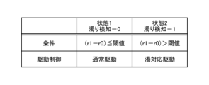
次に、第1の制御装置22は濁りに関する情報に基づいて濁り検知を行う(S43)。 第1の制御装置22は、濁りの検知結果を第2の制御装置32に送信する。第2の制御装置32は、濁りが検知された場合(「濁り検知=1」)には、濁り対応制御(S44)に進み、濁りが検知されていない場合(「濁り検知=0」)には、通常制御(S45)が行われる。例外として、濁りを検知していなくても術者や助手が濁り対応制御を選択した場合には濁りが検知された場合(「濁り検知」=1)と同様に、濁り対応制御S44に遷移する。具体的な濁り検知と濁り対応制御については後述する。後述した濁り検知と濁り対応制御はどの組み合わせを用いてよい。
Next, the
濁り対応制御S44と通常制御S45の後に処置具31の電源がオフになっているかを確認する(S46)。電源がオフになっていない場合(「No」)は、濁り検知S43に戻る。電源がオフになっている場合(「Yes」)は、切削処置が終了する。
After the turbidity countermeasure control S44 and the normal control S45, it is checked whether the power of the
[濁り検知]
次に、具体的に濁りに関する情報に基づいて濁り検知するいくつかの方法について、以下に説明する。ここで、濁りに関する情報とは、内視鏡装置2で生成される撮像データから得られる値や、灌流液の物性値、処置具装置3から取得されたインピーダンス等である。[Turbidity detection]
Next, several methods for turbidity detection based on turbidity-related information will be described below. Here, the turbidity-related information includes values obtained from imaging data generated by the
[濁り検知の第1実施形態:コントラスト]
濁り検知の第1実施形態は、内視鏡装置2で生成される撮像データから濁りに関する情報を取得し、濁りを検知する実施形態である。実施形態は、内視鏡装置2で生成される撮像データを記憶するストレージ(不図示)を備える第1の制御装置22によって実装される。当該ストレージは外部装置でもよい。また、濁り検知の第1実施形態において、検知部は第1の制御装置22に設けられる。[First Embodiment of Turbidity Detection: Contrast]
The first embodiment of turbidity detection is an embodiment in which turbidity is detected by acquiring information about turbidity from imaging data generated by the
次に、濁り検知の第1実施形態の検知方法を具体的に示す。濁り検知の第1実施形態は、内視鏡装置2で生成される撮像データのコントラストで濁りを検知する方法である。
Next, the detection method of the turbidity detection according to the first embodiment will be specifically described. A first embodiment of turbidity detection is a method of detecting turbidity based on the contrast of imaging data generated by the
コントラストで濁り検知する方法の一例を、図4Aを用いて説明する。
第1の制御装置22は、内視鏡装置2からの第1撮像データを読み込み、第1の制御装置22に設けられるストレージに記憶する(S431)。その後、第1の制御装置22は、第1撮像データのコントラストc0(第1の値)を公知の技術を用いて算出する(S432)。次に、第1の制御装置22に設けられる検知部は、内視鏡装置2から出力された第2撮像データを読み込み(S433)、第2撮像データのコントラストc1(第2の値)を公知の技術を用いて算出する(S434)。次に、第1の制御装置22に設けられる検知部は、c0とc1の大小を比較する(S435)。c1の方が小さい場合は、濁りを検知したと判断して、濁り検知=1とする(S436:図5B参照)。c1とc0が等しい、または、c1の方が大きい場合は、濁りを検知していないとして濁り検知=0とする(S437:図5B参照)。検出結果を出したら、濁り検知のフローは終了する。An example of a method of detecting turbidity using contrast will be described with reference to FIG. 4A.
The
なお、第1撮像データは第2撮像データより数秒前、または数フレーム前に撮像されている撮像データである。 Note that the first image data is image data captured several seconds or several frames before the second image data.
また、図5Bの条件と異なる条件を用いる濁り検知の方法を、図4Bを用いて説明する。
第1の制御装置22に設けられる検知部は、あらかじめ設定された閾値を読み込む(S430)。その後、第1の制御装置22に設けられる検知部は、前述のとおりS431からS434まで行う。その後、第1の制御装置22に設けられる検知部は、c0とc1の差分をとって変化量を算出し、算出された変化量に基づいて、濁りが生じているか否かを判定する(S438:図5C参照)。
ここで、閾値とは、あらかじめ数値を設定してもよいし、濁りが発生している画像と濁りが発生していない画像を集めて機械学習を行い算出した閾値を用いてもよい。A turbidity detection method using conditions different from those in FIG. 5B will be described with reference to FIG. 4B.
A detection unit provided in the
Here, the threshold value may be set as a numerical value in advance, or may be a threshold value calculated by performing machine learning by collecting images in which turbidity occurs and images in which turbidity does not occur.
濁りの原因は、例えば骨粉や乳化した髄液等によるものである。よって、濁りの色自体は白色である。よって、通常時と濁り発生時の内視鏡視野を比べるとコントラスト値が低くなる(図5A参照)。これにより、内視鏡21の照明の色に依存せず濁りを検知することができる。
Turbidity is caused by, for example, bone powder, emulsified cerebrospinal fluid, and the like. Therefore, the color of turbidity itself is white. Therefore, when comparing the endoscopic field of view under normal conditions and when turbidity occurs, the contrast value is low (see FIG. 5A). Accordingly, turbidity can be detected without depending on the color of illumination of the
[濁り検知の第1実施形態の第1変形例:エッジ]
次に、濁り検知の第1実施形態の第1変形例を示す。濁り検知の第1実施形態の第1変形例は、第1の制御装置22に設けられる検知部が、第1撮像データと第2撮像データのエッジを比較し、エッジの変化量に基づいて濁りを検知する方法である。
ここで、第1撮像データは第2撮像データより数秒前、または数フレーム前に撮像されている撮像データである。[First Modification of First Embodiment of Turbidity Detection: Edge]
Next, the 1st modification of 1st Embodiment of turbidity detection is shown. A first modification of the first embodiment of turbidity detection is a method in which a detection unit provided in the
Here, the first image data is image data captured several seconds or several frames before the second image data.
濁りが発生すると生体組織(例えば骨)や処置具31が見えなくなる。すなわち、生体組織のエッジや処置具31のエッジが撮像できなくなる(図6A参照)。よって、エッジの減少を検知することで濁りを検知する。これにより、内視鏡の照明の色に依存せず濁りを検知することができる。
When turbidity occurs, living tissue (for example, bone) and the
濁り検知の具体的な流れは、図4Aと同様である。第1の制御装置22に設けられる検知部は、S432におけるc0の算出に替えて、第1撮像データから公知の技術を用いてエッジe0を算出する。その後、S435で用いられる濁り検知の条件(c0≦c1)の判断に変えて算出された、エッジe0と、同様に、第2撮像データから公知の技術を用いて算出されるエッジe1とを用いて濁り検知の条件を説明する。
e1がe0より小さければ、関節腔C1内に濁りが発生したとして、S436と同様に濁りを検知する(図6B参照)。逆にe1がe0と等しい、または、e0より大きければ、関節腔C1内の濁りは発生していない、または、減っているとして、S437と同様に濁りを検知しない(図6B参照)。A specific flow of turbidity detection is the same as in FIG. 4A. Instead of calculating c0 in S432, the detection unit provided in the
If e1 is smaller than e0, it is assumed that turbidity has occurred in the joint cavity C1, and turbidity is detected in the same manner as in S436 (see FIG. 6B). Conversely, if e1 is equal to e0 or is greater than e0, it is determined that turbidity in the joint cavity C1 has not occurred or has decreased, and turbidity is not detected as in S437 (see FIG. 6B).
前述では、単純にe0とe1の値を比較したが、図4Bのように閾値を設けて、e0とe1の差分と閾値の比較により濁りを検出してもよい(図6C参照)。
ここで、閾値とは、あらかじめ数値を設定してもよいし、濁りが発生している画像と濁りが発生していない画像を集めて機械学習を行い算出した閾値を用いてもよい。In the above description, the values of e0 and e1 are simply compared, but turbidity may be detected by setting a threshold as shown in FIG. 4B and comparing the difference between e0 and e1 with the threshold (see FIG. 6C).
Here, the threshold value may be set as a numerical value in advance, or may be a threshold value calculated by performing machine learning by collecting images in which turbidity occurs and images in which turbidity does not occur.
[濁り検知の第1実施形態の第2変形例:輝度]
次に、濁り検知の第1実施形態の第2変形例を示す。濁り検知の第1実施形態の第2変形例は、第1撮像データと第2撮像データの輝度を比較し、輝度の変化量に基づいて濁りを検知する方法である。
ここで、第1撮像データは第2撮像データより数秒前、または数フレーム前に撮像されている撮像データである。[Second Modification of First Embodiment of Turbidity Detection: Luminance]
Next, the 2nd modification of 1st Embodiment of turbidity detection is shown. A second modification of the turbidity detection of the first embodiment is a method of comparing the brightness of the first imaging data and the second imaging data and detecting turbidity based on the amount of change in brightness.
Here, the first image data is image data captured several seconds or several frames before the second image data.
濁りは、前述したように白色である。よって、通常時と濁り発生時を比べると輝度が高くなる(図7A参照)。これにより、内視鏡の照明の色に依存せず濁りを検出することができる。 Turbidity is white, as previously described. Therefore, the brightness is higher when comparing the normal time and the time when turbidity occurs (see FIG. 7A). As a result, turbidity can be detected without depending on the color of illumination of the endoscope.
濁り検知の具体的な流れは、図4Aと同様である。第1の制御装置22に設けられる検知部は、S432におけるc0の算出に替えて、第1撮像データから公知の技術を用いて輝度r0を算出する。その後、S435で用いられる濁り検知の条件(c0≦c1)の判断に替えて算出された、輝度r0と、同様に、第2撮像データから公知の技術を用いて算出される輝度r1とを用いて濁り検知の条件を説明する。
r1がr0より大きければ関節腔C1内に濁りが発生したとして、S436と同様に濁りを検知する。逆にr1がr0と等しい、または、r0より小さければ、関節腔C1内の濁りは発生していない、または、減っているとして、S437と同様に濁りを検知しない(図7B参照)。A specific flow of turbidity detection is the same as in FIG. 4A. Instead of calculating c0 in S432, the detection unit provided in the
If r1 is greater than r0, it is assumed that turbidity has occurred in the joint cavity C1, and turbidity is detected in the same manner as in S436. Conversely, if r1 is equal to r0 or smaller than r0, turbidity is not detected in the same way as in S437, assuming that turbidity in the joint cavity C1 has not occurred or has decreased (see FIG. 7B).
前述では、単純にr0とr1の値を比較したが、図4Bのように閾値を設けて、r0とr1の差分(変化量)と閾値の比較により濁りを検知してもよい(図7C参照)。
ここで、閾値とは、あらかじめ数値を設定してもよいし、濁りが発生している画像と濁りが発生していない画像を集めて機械学習を行い算出した閾値を用いてもよい。In the above description, the values of r0 and r1 are simply compared, but a threshold may be provided as shown in FIG. 4B, and turbidity may be detected by comparing the difference (change amount) between r0 and r1 with the threshold (see FIG. 7C).
Here, the threshold value may be set as a numerical value in advance, or may be a threshold value calculated by performing machine learning by collecting images in which turbidity occurs and images in which turbidity does not occur.
[濁り検知の第1実施形態の第3変形例:画像差分]
次に、濁り検知の第1実施形態の第3変形例を示す。濁り検知の第1実施形態の第3変形例は、第1撮像データと第2撮像データの画素を比較し、画素の変化量を算出し、画素の変化量と閾値を比較して濁りを検知する方法である。
ここで、第1撮像データは第2撮像データより数秒前、または数フレーム前に撮像されている撮像データである。[Third Modification of Turbidity Detection First Embodiment: Image Difference]
Next, the 3rd modification of 1st Embodiment of turbidity detection is shown. A third modification of the first embodiment of turbidity detection is a method of comparing pixels of the first imaging data and the second imaging data, calculating the amount of change in pixels, and comparing the amount of change in pixels with a threshold value to detect turbidity.
Here, the first image data is image data captured several seconds or several frames before the second image data.
濁り検知の具体的な流れは、S432とS434を除き図4Bと同様である。第1の制御装置22に設けられる検知部は、S432におけるc1の算出を行わず、S434におけるc1の算出に替えて第1撮像データと第2の撮像データの同一の座標の画素を取得し差分をとり、各座標の画素の変化量の絶対値和nを算出する。その後、S438の濁り条件で用いられる濁り検知の条件(c1-c0≧閾値)の判断に替えて算出された、絶対値和nとS430で読み込まれた閾値とを用いて濁り検知の条件を説明する。nが閾値より大きければ関節腔C1内に濁りが発生したとして、S436と同様に、濁りを検知する。逆にnと閾値が等しい、または、nが閾値より小さければ、関節腔C1内の濁りは発生していない、または、減っているとして、S437と同様に、濁りを検知しない(図8B参照)。
A specific flow of turbidity detection is the same as in FIG. 4B except for S432 and S434. The detection unit provided in the
濁りが発生すると、撮像データの画素に変化が現れる(図8A参照)。その変化を検出することにより濁りが検知できる。 When turbidity occurs, changes appear in the pixels of the imaging data (see FIG. 8A). Turbidity can be detected by detecting the change.
[濁り検知の第2実施形態:灌流液のpHから濁り検知]
第2実施形態は、灌流液の物性値から濁りを検知する手段である。[Second Embodiment of Turbidity Detection: Detection of Turbidity from pH of Perfusate]
The second embodiment is means for detecting turbidity from the physical property values of the perfusate.
排液ボトル64または内視鏡21の挿入部211は、灌流液のpHを検出するpHセンサー(不図示)を備える。当該ストレージは外部装置でもよい。排液ボトル64または内視鏡21の挿入部211に設けられるpHセンサーは、灌流液に接触可能な位置に配置されている。検知部が設けられる第1の制御装置22は、排液ボトル64または内視鏡21の挿入部211に設けられるpHセンサーからの検出値を受信可能なように、有線または無線でpHセンサーと接続している。
The
濁りは、例えば処置具31の処置によって発生した骨や髄液等が原因である。よって、濁りが発生していない状態と濁り発生している状態を比べると灌流液のpHが変化する。この灌流液のpHの変化を検出することにより、骨や髄液による濁りを検知することができる。
Turbidity is caused by, for example, bones and cerebrospinal fluid generated by treatment with the
濁り検知の具体的な流れの一例を図9A説明する。
まず、第1制御装置22に設けられる検知部は、あらかじめ設定されている第1pHw0を読み込む(S4310)。次に、第1制御装置22に設けられる検知部は、排液ボトル64または内視鏡21の挿入部211に設けられるpHセンサーから検出される第2pHw1を受信する(S4311)。その後、第1制御装置22に設けられる検知部に記憶されている第1pHw0と排液ボトル64または内視鏡21の挿入部211に設けられるpHセンサーから取得したpHw1を比較する(S4312)。w1がw0より大きければ(「No」)、関節腔C1内に濁りが発生したとして濁りを検知する(S4313:図9C参照)。逆にw1がw0と等しい、または、w0より小さい(「Yes」)であれば、関節腔C1内の濁りは発生していない、または、減っているとして、濁りを検出しない(S4314)。
An example of a specific flow of turbidity detection will be described with reference to FIG. 9A.
First, the detector provided in the
また、図9Aの条件と異なる条件を用いる濁り検知の方法を、図9Bを用いて説明する。
第1制御装置22に設けられる検知部は、あらかじめ設定された閾値を読み込む(S439)。その後、前述のとおり第1制御装置22に設けられる検知部は、S4310からS4311まで行う。その後、第1制御装置22に設けられる検知部は、w0とw1の差分をとって変化量を算出し、算出された変化量に基づいて、濁りが生じているか否かを判定する(S4315:図9D参照)。
ここで、閾値とは、あらかじめ数値を設定してもよいし、濁り発生時の灌流液のpHと通常時の灌流液のpHを集めて機械学習を行い算出した閾値を用いてもよい。
A turbidity detection method using conditions different from those in FIG. 9A will be described with reference to FIG. 9B.
The detection unit provided in the
Here, the threshold may be a numerical value set in advance, or may be a threshold calculated by machine learning by collecting the pH of the perfusate when turbidity occurs and the pH of the perfusate when normal.
[濁り検知の第3実施形態:処置具のインピーダンス(粘性)から濁り検知]
濁り検知の第3実施形態は、処置具31から取得されるインピーダンスに基づいて濁りを検知する方法である。当該方法は、ストレージ(不図示)を備える第2の制御装置32によって実装され、検知部は第2の制御装置32に設けられる。当該ストレージは外部装置でもよい。[Third Embodiment of Turbidity Detection: Detection of Turbidity from Impedance (Viscosity) of Treatment Instrument]
The third embodiment of turbidity detection is a method of detecting turbidity based on impedance acquired from the
濁り検知の第3実施形態は、第2の制御装置32に設けられる未図示の検知部が、処置具31を定電圧制御或いは定電流制御をするために供給される電流及び電圧を基にインピーダンスを算出し、算出したインピーダンスから濁りを検出する方法である。
The third embodiment of turbidity detection is a method in which a detection unit (not shown) provided in the
濁りは、例えば処置具31の処置によって発生した骨や髄液等が原因である。灌流液に骨や髄液といった生体組織が混ざると灌流液の粘性が変化する。灌流液の粘性が変化すると、処置具31のインピーダンスが変化する。よって、濁りが発生していない状態と濁り発生している状態を比べると処置具31から取得されるインピーダンスが変化する。これより、インピーダンスの変化から粘性を予測し、濁りを検出することができる。
Turbidity is caused by, for example, bones and cerebrospinal fluid generated by treatment with the
濁り検知の具体的な流れは、図9Aと同様である。
第2の制御装置32に設けられる検知部は、S4310のw0に替えてあらかじめ設定される第1インピーダンスi0を読み込む。その後、S4311のw1に替えて任意のタイミングで算出される第2インピーダンスi1を算出する。S4312における濁り検知(w0≧w1)に替えて、読み込まれた第1インピーダンスi0と算出された第2インピーダンスi1を用いて濁り検知の条件を説明する。
i1がi0より大きければ(「No」)、関節腔C1内に濁りが発生したとして、S4313と同様に、濁りを検知する(「濁り検知」=1:図10A参照)。逆にi1がi0と等しい、または、i0より小さければ(「Yes」)、関節腔C1内の濁りは発生していない、または、減っているとして、S4314と同様に、濁りを検知しない(「濁り検知」=0)。A specific flow of turbidity detection is the same as in FIG. 9A.
The detection unit provided in the
If i1 is greater than i0 (“No”), it is assumed that turbidity has occurred in the joint cavity C1, and turbidity is detected in the same manner as in S4313 (“turbidity detection”=1: see FIG. 10A). Conversely, if i1 is equal to i0 or smaller than i0 (“Yes”), it is assumed that turbidity in the joint cavity C1 has not occurred or is decreasing, and turbidity is not detected (“turbidity detected”=0), as in S4314.
前述では、単純にi0とi1の値を比較したが、図9Bのように閾値を設けて、i0とi1の差分と閾値の比較により濁りを検出してもよい(図10B参照)。
ここで、閾値とは、あらかじめ数値を設定してもよいし、濁り発生時のインピーダンスと通常時のインピーダンスを集めて機械学習を行い算出した閾値を用いてもよい。Although the values of i0 and i1 are simply compared in the above description, turbidity may be detected by comparing the difference between i0 and i1 with the threshold as shown in FIG. 9B (see FIG. 10B).
Here, the threshold value may be set to a numerical value in advance, or may be a threshold value calculated by performing machine learning by collecting the impedance when turbidity occurs and the impedance when normal.
[濁り検知のその他の応用例]
上記記載した濁り検知の方法は、組み合わせて使用してもよい。
2つの濁り検知を組み合わせて使う場合は、両方の検知方法でも濁りを検知した時に濁り検知=1としてもよい。この場合は、どちらかが誤作動で濁りを検知してしまっても、両方が濁りを検知しないと濁り検知=1とならないので、慎重に濁り検知を行うことができる。
また、どちらか一方の検知方法が濁りを検出した時に濁り検知=1としてもよい。この場合は、小さい変化でも濁りを検知することができる。[Other application examples of turbidity detection]
The methods of turbidity detection described above may be used in combination.
When using two turbidity detections in combination, turbidity detection may be set to 1 when turbidity is detected in both detection methods. In this case, even if one of them malfunctions and detects turbidity, the turbidity detection = 1 will not occur unless both detect turbidity, so turbidity detection can be performed carefully.
Further, turbidity detection may be set to 1 when one of the detection methods detects turbidity. In this case, even a small change can detect turbidity.
複数の濁り検知方法を組み合わせて使う場合は、検知方法ごとに重みづけをしたうえで、濁り検知を行ってもよい。 When a plurality of turbidity detection methods are used in combination, each detection method may be weighted before turbidity detection.
[濁り対応制御]
次に、図3に示す濁り対応制御S44の具体例を示す。以下に記載する濁り対応制御の実施形態は上記の濁り検知と組み合わせることができる。
ここで、制御部は、第1の制御装置22または第2の制御装置32の少なくとも1つに設けられ、検知部での検知結果を無線または有線を介して送受信を行えるように構成されている。制御部は、取得した検知結果を基に、濁り対応制御を行う。このように、検知部での検知結果を制御部に伝えることができる構成としたことによって、検知部の配置に関わらず、制御部が濁り対応制御を行うことを可能にした。[Control for turbidity]
Next, a specific example of the turbidity countermeasure control S44 shown in FIG. 3 will be shown. The turbidity response control embodiments described below can be combined with the turbidity detection described above.
Here, the control section is provided in at least one of the
[濁り対応制御の第1実施形態:エッジ重畳画像表示]
初めに、濁り対応制御の第1実施形態を示す。濁り対応制御の第1実施形態は、第1の制御装置22または第2の制御装置32の少なくとも1つに設けられる検知部から濁り検知結果=1を受信すると、表示装置23に出力される内視鏡視野の映像に処置具31や生体組織のエッジが強調された画像が重畳される(図11参照)濁り対応制御である。
本実施形態において、制御部は第1の制御装置22に設けられる。
一方、本実施形態における通常制御は、エッジが強調された画像が重畳されていない内視鏡視野の映像を表示装置23に出力する制御を行う。[First Embodiment of Turbidity Countermeasure Control: Edge Superimposed Image Display]
First, a first embodiment of turbidity countermeasure control will be shown. The first embodiment of the turbidity countermeasure control is turbidity countermeasure control in which, when a turbidity detection result=1 is received from a detection unit provided in at least one of the
In this embodiment, the controller is provided in the
On the other hand, the normal control in the present embodiment performs control for outputting to the
表示装置23に出力される内視鏡視野の映像に処置具31や生体組織のエッジが強調された画像が重畳されることで、濁りがある状態でも処置具31の位置や生体組織の場所を視認できるので、術者は手技を続行することができる。
By superimposing the edge-enhanced image of the
次に、濁り対応制御の第1実施形態の流れを具体的に説明する。
第1の制御装置22または第2の制御装置32の少なくとも1つに設けられる検知部から第1の制御装置22に設けられる制御部に対して濁りを検知する信号が送られると、第1の制御装置22に設けられる制御部が撮像データを取得し、公知の方法でエッジを抽出する。その後、第1の制御装置22に設けられる制御部がエッジを抽出して生成したエッジ強調画像データと撮像データから生成した通常の画像データを重畳し、表示装置23で表示を行う。Next, the flow of the turbidity countermeasure control according to the first embodiment will be specifically described.
When a detection unit provided in at least one of the
[濁り対応制御の第2実施形態:処置具31の駆動電力調整]
次に、濁り対応制御の第2実施形態を示す。濁り対応制御の第2実施形態は、第1の制御装置22または第2の制御装置32の少なくとも1つに設けられる検知部から濁り検知結果=1を制御部が受信すると、処置具31の駆動電力を低くして第2の駆動電力とする濁り対応制御である。
本実施形態において、制御部は第2の制御装置32に設けられる。
一方、本実施形態における通常制御は、第2の駆動電力より大きい駆動電力である第1の駆動電力で処置具31を駆動させる制御である。[Second embodiment of turbidity countermeasure control: driving power adjustment of treatment instrument 31]
Next, a second embodiment of turbidity countermeasure control will be described. The second embodiment of the turbidity countermeasure control is turbidity countermeasure control in which, when the control unit receives the turbidity detection result=1 from the detection unit provided in at least one of the
In this embodiment, the controller is provided in the
On the other hand, the normal control in the present embodiment is control for driving the
濁り対応制御の第2実施形態の流れを具体的に説明する。
第1の制御装置22または第2の制御装置32の少なくとも1つに設けられる検知部から第2の制御装置32に設けられる制御部に対して濁りを検知する信号が送られると、第2の制御装置32に設けられた制御部が処置具31に供給する駆動電力を調整する。その結果、処置具31は第1の駆動電力より低い第2の駆動電力で超音波振動を行う。The flow of the second embodiment of turbidity countermeasure control will be specifically described.
When a detection unit provided in at least one of the
処置具31の駆動電力を落とすことで切削速度を落とし、切削によって発生する生体組織を減らすことができる。その結果として、灌流の速度が濁り発生時と通常時で変化しないので、内視鏡視野内の濁りが減少する。
これにより、処置具31の超音波振動を止めることなく、術者は手技を中断せず継続して行うことができる。By reducing the driving power of the
As a result, the operator can continue the procedure without stopping the ultrasonic vibration of the
[濁り対応制御の第2実施形態の第1変形例:処置具31の駆動電力調整]
次に、濁り対応制御の第2実施形態の第1変形例を示す。濁り対応制御の第2実施形態の第1変形例は、濁りを検知すると第1の駆動電力より大きい第3の駆動電力で処置具31を駆動させる濁り対応制御である。
また、本実施形態の本変形例における通常制御は、第3の駆動電力より小さい駆動電力である第1の駆動電力で処置具31を駆動させる制御である。[First Modification of Second Embodiment of Turbidity Countermeasure Control: Driving Power Adjustment of Treatment Instrument 31]
Next, the 1st modification of 2nd Embodiment of the turbidity correspondence control is shown. A first modification of the second embodiment of the turbidity countermeasure control is turbidity countermeasure control that drives the
Further, the normal control in this modified example of the present embodiment is control for driving the
濁り対応制御の第2実施形態の第1変形例を示す。流れを具体的に説明する。
第1の制御装置22または第2の制御装置32の少なくとも1つに設けられる検知部から第2の制御装置32に設けられる制御部に対して濁りを検知する信号が送られると、第2の制御装置32に設けられる制御部が処置具31に供給する駆動電力を調整する。その結果、処置具31は第1の駆動電力より大きい第3の駆動電力で超音波振動を行う。The 1st modification of 2nd Embodiment of the turbidity correspondence control is shown. The flow will be explained concretely.
When a detection unit provided in at least one of the
切削処置具の駆動電力を上げることで切削速度を上昇させ、短時間で処置を済ませることができる。この方法では、骨粉の発生量も増えるため、灌流速度を速く設定するとより効果的である。 By increasing the driving power of the cutting treatment tool, the cutting speed can be increased and the treatment can be completed in a short time. This method also increases the amount of bone powder generated, so setting a faster perfusion rate is more effective.
[濁り対応制御の第2実施形態の第2変形例:処置具31の駆動電力調整]
次に、濁り対応制御の第2実施形態の第2変形例を示す。濁り対応制御の第2実施形態の第2変形例は、濁りを検知すると処置具31の駆動が停止と発信を繰り返す濁り対応制御である。
また、本実施形態の本変形例における通常制御は、断続的に処置具31を駆動させる制御である。[Second Modification of Second Embodiment of Turbidity Response Control: Adjustment of Driving Power of Treatment Instrument 31]
Next, a second modified example of the second embodiment of the turbidity countermeasure control will be shown. A second modified example of the second embodiment of the turbidity countermeasure control is turbidity countermeasure control in which, when turbidity is detected, driving of the
Further, the normal control in this modified example of the present embodiment is control for intermittently driving the
濁り対応制御の第2実施形態の第2変形例の流れを具体的に説明する。
第1の制御装置22または第2の制御装置32の少なくとも1つに設けられる検知部から第2の制御装置32に設けられる制御部に対して濁りを検知する信号が送られると、第2の制御装置32に設けられる制御部が処置具31に供給する駆動電力を停止したり供給したりを繰り返す制御を行う。The flow of the second modified example of the second embodiment of the turbidity countermeasure control will be specifically described.
When a detection unit provided in at least one of the
処置具31を発振させたり停止させたりを繰り返すことによって、連続的に発振させた場合より切削時の骨粉の量は少なくなる。よって、内視鏡視野の濁りを解消しつつ、術者の手技を続行することができる。
By repeatedly oscillating and stopping the
[濁り対応制御の第3実施形態:灌流制御]
次に、濁り対応制御の第3実施形態を示す。濁り対応制御の第3実施形態は、濁りを検知すると灌流装置6の送水量が増加する(送水速度を強める)対応制御である。[Third embodiment of turbidity countermeasure control: perfusion control]
Next, a third embodiment of turbidity countermeasure control will be described. The third embodiment of the turbidity countermeasure control is a countermeasure control that increases the water supply amount of the perfusion device 6 (increases the water supply speed) when turbidity is detected.
本実施形態の手術システム1Aの構成は、図12に示す。
手術システム1との相違点のみを説明する。灌流装置6に送水ポンプ63が設けられる。
本実施形態において、制御部は送水ポンプ63または第1の制御装置22に設けられる。
制御部が第1の制御装置22に設けられる場合は、第1の制御装置22と送水ポンプ63が無線または有線で信号が送受信できるように構成されている。
送水ポンプ63または第1の制御装置22に設けられる制御部は、取得した検知結果をもとに、液体源61から内視鏡21に向けて流れる灌流液の送水量を増加させて第2の送水量とする信号を生成し、送水ポンプ63に対して制御を行う。
一方、本実施形態における通常制御は、第2の送水量より小さい第1の送水量で送水を行う制御である。The configuration of the
Only differences from the surgical system 1 will be described. A
In this embodiment, the controller is provided in the
When the control unit is provided in the
The control unit provided in the
On the other hand, the normal control in the present embodiment is control for supplying water at a first water supply amount smaller than the second water supply amount.
濁り対応制御の第3実施形態の流れを具体的に説明する。第1の制御装置22または第2の制御装置32の少なくとも1つに設けられる検知部から送水ポンプ63または第1の制御装置22に設けられる制御部に対して濁りを検知する信号が送られると、送水ポンプ63または第1の制御装置22制御部が第1の送水量より大きい第2の送水量で灌流液を送水する制御を行う。
The flow of the turbidity countermeasure control of the third embodiment will be specifically described. When a detection unit provided in at least one of the
第1の送水量より大きい第2の送水量で灌流液を送水することによって、濁りの原因の一例である骨や髄液などの生体組織が関節腔C1から排液チューブ65を通して排液ボトル64により排出されやすくなる。これにより、内視鏡視野の濁りが解消され術者の手技が続行できる。
By supplying the perfusate at a second water supply amount larger than the first water supply amount, biological tissues such as bones and cerebrospinal fluid, which are examples of the cause of turbidity, are easily discharged from the joint cavity C1 through the
[濁り対応制御の第3実施形態の第1変形例:灌流制御]
次に、濁り対応制御の第3実施形態の第1変形例を示す。濁り対応制御の第3実施形態の第1変形例は、濁りを検知すると灌流装置6の灌流液の吸引量が増加する対応制御である。[First modification of third embodiment of turbidity countermeasure control: perfusion control]
Next, the 1st modification of 3rd Embodiment of the turbidity correspondence control is shown. A first modified example of the turbidity countermeasure control of the third embodiment is a countermeasure control in which the amount of perfusate aspirated by the
本実施形態の本変形例の手術システム1Bの構成を図13に示す。手術システム1との相違点のみを説明する。灌流装置6に吸引ポンプ66が設けられる。吸引ポンプ66は、灌流液を排液チューブ65の流路を辿って、関節腔C1内の灌流液を排液ボトル64に排出するための吸引量を第1の吸引量より大きい第2の吸引量に増加させる制御を行う。
本実施形態の本変形例において、制御部は吸引ポンプ66または第1の制御装置22に設けられる。
制御部が第1の制御装置22に設けられる場合は、第1の制御装置22と吸引ポンプ66が無線または有線で信号が送受信できるように構成されている。
吸引ポンプ66または第1の制御装置22に設けられる制御部は、取得した検知結果をもとに、関節腔C1内の灌流液を排液ボトル64に排出するための吸引量を増加させて第2の吸引量とする信号を生成し、吸引ポンプ66に対して制御を行う。
一方、本実施形態の本変形例における通常制御は、第2の吸引量より小さい第1の吸引量で吸引を行う制御である。FIG. 13 shows the configuration of a
In this modified example of the present embodiment, the controller is provided in the
When the control section is provided in the
The controller provided in the
On the other hand, the normal control in this modified example of the present embodiment is control for performing suction with a first suction amount that is smaller than the second suction amount.
濁り対応制御の第3実施形態の流れを具体的に説明する。第1の制御装置22または第2の制御装置32の少なくとも1つに設けられる検知部から吸引ポンプ66または第1の制御装置22に設けられる制御部に対して濁りを検知する信号が送られると、吸引ポンプ66または第1の制御装置22に設けられる制御部が灌流液の吸引量を第2の吸引量に増加させる制御を行う。
The flow of the turbidity countermeasure control of the third embodiment will be specifically described. When a detection unit provided in at least one of the
灌流液の吸引量を第2の吸引量に増加させることによって、濁りの原因の一例である骨や髄液などの生体組織が関節腔C1から排液チューブ65を通して排液ボトル64により排出されやすくなる。これにより、内視鏡視野の濁りが解消され術者の手技が続行できる。
By increasing the suction amount of the perfusate to the second suction amount, living tissues such as bones and cerebrospinal fluid, which are examples of the cause of turbidity, are easily discharged from the joint cavity C1 through the
[濁り対応制御の第3実施形態の第2変形例:灌流制御]
次に、濁り対応制御の第3実施形態の第2変形例を示す。濁り対応制御の第3実施形態の第2変形例は、濁りを検知すると灌流装置6の灌流液の吸引量と送水量が増加する対応制御である。[Second modification of third embodiment of turbidity countermeasure control: perfusion control]
Next, the 2nd modification of 3rd Embodiment of the turbidity correspondence control is shown. A second modification of the turbidity countermeasure control of the third embodiment is a countermeasure control in which the amount of perfusate aspirated and the amount of water supplied to the
本実施形態の本変形例の手術システム1Cの構成は、図14に示す。手術システム1との相違点のみを説明する。灌流装置6に送水ポンプ63と吸引ポンプ66が設けられる。
本実施形態において、制御部は送水ポンプ63と吸引ポンプ66の両方、または、第1の制御装置22に設けられる。
制御部が第1の制御装置22に設けられる場合は、第1の制御装置22と送水ポンプ63と吸引ポンプ66が無線または有線で信号が送受信できるように構成されている。
送水ポンプ63と吸引ポンプ66の両方または第1の制御装置22に設けられる制御部は、取得した検知結果をもとに、液体源61から内視鏡21に向けて流れる灌流液の送水量を増加させて第2の送水量とする信号を生成し、送水ポンプ63に対して制御を行い、また、関節腔C1内の灌流液を排液ボトル64に排出するための吸引量を増加させて第2の吸引量とする信号を生成し、吸引ポンプ66に対して制御を行う。FIG. 14 shows the configuration of a
In this embodiment, the controller is provided in both the
When the control unit is provided in the
Based on the obtained detection result, both the
濁り対応制御の第3実施形態の流れを具体的に説明する。第1の制御装置22または第2の制御装置32の少なくとも1つに設けられる検知部から送水ポンプ63と吸引ポンプ66の両方、または、第1の制御装置22に設けられる制御部に対して濁りを検知する信号が送られると、送水ポンプ63と吸引ポンプ66の両方、または、第1の制御装置22に設けられる制御部が灌流液の送水量を第2の送水量に増加させる制御を行い、さらに、灌流液の吸引量を第2の吸引量に増加させる制御を行う。
また、本実施形態の本変形例における通常制御は、第2の送水量より小さい第1の送水量で送水を行う制御かつ、第2の吸引量より小さい第1の吸引量で吸引を行う制御である。The flow of the turbidity countermeasure control of the third embodiment will be specifically described. When a detection unit provided in at least one of the
Further, the normal control in this modified example of the present embodiment is control for feeding water at a first water feeding rate that is smaller than the second water feeding rate and control for suctioning at a first suction rate that is smaller than the second suction rate.
灌流液の送水量と吸引量を増加させることによって、濁りの一例である骨や髄液などの生体組織が関節腔C1から排液チューブ65を通して排液ボトル64により排出されやすくなる。これにより、内視鏡視野の濁りが解消され術者の手技が続行できる。
By increasing the amount of water supply and suction of the perfusate, living tissue such as bones and cerebrospinal fluid, which are examples of turbidity, can be easily discharged from the joint cavity C1 through the
灌流液の送水量と吸引量の増加量が同じになるように制御を行ってもよい。これにより、関節腔C1内の灌流液の量が一定に保たれ、患者への負担が少なくなる。 Control may be performed so that the increase in the amount of perfusate supplied and the amount of suction is the same. As a result, the amount of perfusate in the joint cavity C1 is kept constant, and the burden on the patient is reduced.
灌流液の送水量を第2の送水量に増加させた後、灌流液の吸引量を第2の吸引量に増加させるように、灌流液の送水量と吸引量を増加させるタイミングをずらしてもよい。これにより、関節腔C1内の灌流液の量が一時的に少なくなることがなくなり手技が続行しやすくなる。 After increasing the perfusate supply amount to the second water supply amount, the timing of increasing the perfusate supply amount and the suction amount may be shifted so that the perfusate suction amount is increased to the second water supply amount. As a result, the amount of perfusate in the joint cavity C1 does not temporarily decrease, making it easier to continue the procedure.
灌流液の吸引量を第2の吸引量に増加させた後、灌流液の送水量を第2の送水量に増加させるように増加させるタイミングをずらしてもよい。これにより、関節腔C1内の灌流液の量が一時的に多くなることがなくなり患者への負担が少なくなる。 After increasing the suction amount of the perfusate to the second suction amount, the timing of increasing the supply amount of the perfusate to the second water supply amount may be shifted. As a result, the amount of perfusate in the joint cavity C1 does not temporarily increase, thereby reducing the burden on the patient.
[濁り対応制御のその他の応用例]
上記記載した濁り対応制御は、濁り対応制御同士を組み合わせて使うこともできる。これにより、より術者が中断しにくい状況を作ることができる。[Other application examples of turbidity control]
The turbidity response control described above can also be used in combination with the turbidity response control. This makes it possible to create a situation in which it is more difficult for the operator to interrupt.
以上のように、本発明にかかる手術システム、制御装置および手術システムの作動方法は、灌流液中の濁りを検知し、所定の制御を行うことによって患者・術者にとって負担を軽減するのに有用である。 INDUSTRIAL APPLICABILITY As described above, the surgical system, control device, and operation method of the surgical system according to the present invention are useful in reducing the burden on patients and operators by detecting turbidity in perfusate and performing predetermined control.
1、1A~1C 手術システム
2 内視鏡装置
3 処置具装置
6 灌流装置
21 内視鏡
22 第1の制御装置
23 表示装置
31 処置具
32 第2の制御装置
33 フットスイッチ
61 液体源
62 送液チューブ
63 送水ポンプ
64 排液ボトル
65 排液チューブ
66 吸引ポンプ
211 挿入部
311 本体
311a 超音波振動子
313 シース
C1 関節腔
J1 膝関節
P1 第1のポータル
P2 第2のポータル
Claims (26)
液中で生体組織を処置する処置具装置と、
前記処置具装置によって発生した前記液中の濁りに関する情報を検知する検知部と、
前記検知部の検知結果に基づいて、前記手術システムの制御を行う制御部と、
を有し、
前記制御部は、前記処置具装置の駆動電力を下げる、
手術システム。 A surgical system,
a treatment instrument device for treating a living tissue in a liquid;
a detection unit that detects information about turbidity in the liquid generated by the treatment instrument device;
a control unit that controls the surgical system based on the detection result of the detection unit;
has
The control unit reduces driving power of the treatment instrument device,
surgical system.
液中で生体組織を処置する処置具装置と、
前記処置具装置によって発生した前記液中の濁りに関する情報を検知する検知部と、
前記検知部の検知結果に基づいて、前記手術システムの制御を行う制御部と、
を有し、
前記制御部は、前記処置具装置の駆動電力を上げる、
手術システム。 A surgical system,
a treatment instrument device for treating a living tissue in a liquid;
a detection unit that detects information about turbidity in the liquid generated by the treatment instrument device;
a control unit that controls the surgical system based on the detection result of the detection unit;
has
The control unit increases driving power of the treatment instrument device,
surgical system.
請求項1または2に記載の手術システム。 The information on the turbidity is a value that increases or decreases in correlation with the occurrence of turbidity,
The surgical system according to claim 1 or 2 .
請求項1または2に記載の手術システム。 The turbidity-related information is information derived from living tissue,
The surgical system according to claim 1 or 2 .
を備え、
前記第1の制御装置は、前記検知部を備え、前記内視鏡装置による撮像データから前記濁りに関する情報を検知する、
請求項1または2に記載の手術システム。 An endoscope device comprising: an endoscope device for imaging a treatment target; and a first control device for converting imaging data obtained from the endoscope device into image data;
with
The first control device includes the detection unit and detects information about the turbidity from image data captured by the endoscope device.
The surgical system according to claim 1 or 2 .
前記検知部は、
前記内視鏡装置から第1撮像データを取得し、
前記ストレージから第2撮像データを取得し、
前記第1撮像データと前記第2撮像データの同一座標の画素の値の変化量を算出し、
前記変化量に応じて前記濁りを検知する、
請求項5に記載の手術システム。 further comprising a storage for storing imaging data of the endoscope device,
The detection unit is
Acquiring first imaging data from the endoscope device,
Acquiring second imaging data from the storage,
calculating the amount of change in the value of a pixel at the same coordinates of the first imaging data and the second imaging data;
detecting the turbidity according to the amount of change;
The surgical system according to claim 5 .
前記検知部は、
前記内視鏡装置から第1撮像データを取得し、
前記ストレージから第2撮像データを取得し、
前記第1撮像データと前記第2撮像データのコントラストの変化量を算出し、
前記変化量によって前記濁りを検知する、
請求項5に記載の手術システム。 further comprising a storage for storing imaging data of the endoscope device,
The detection unit is
Acquiring first imaging data from the endoscope device,
Acquiring second imaging data from the storage,
calculating an amount of change in contrast between the first imaging data and the second imaging data;
detecting the turbidity by the amount of change;
The surgical system according to claim 5 .
前記検知部は、
前記内視鏡装置から第1撮像データを取得し、
前記ストレージから第2撮像データを取得し、
前記第1撮像データと前記第2撮像データのエッジの変化量を算出し、
前記変化量によって前記濁りを検知する、
請求項5に記載の手術システム。 further comprising a storage for storing imaging data of the endoscope device,
The detection unit is
Acquiring first imaging data from the endoscope device,
Acquiring second imaging data from the storage,
calculating an edge change amount between the first imaging data and the second imaging data;
detecting the turbidity by the amount of change;
The surgical system according to claim 5 .
前記検知部は、
前記内視鏡装置から第1撮像データを取得し、
前記ストレージから第2撮像データを取得し、
前記第1撮像データと前記第2撮像データの輝度の変化量を算出し、
前記変化量によって前記濁りを検知する、
請求項5に記載の手術システム。 further comprising a storage for storing imaging data of the endoscope device,
The detection unit is
Acquiring first imaging data from the endoscope device,
Acquiring second imaging data from the storage,
calculating an amount of change in luminance between the first imaging data and the second imaging data;
detecting the turbidity by the amount of change;
The surgical system according to claim 5 .
請求項1または2に記載の手術システム。 The detection unit detects information about the turbidity from the liquid,
The surgical system according to claim 1 or 2 .
前記センサーから取得した前記pHの値に基づいて前記濁りを検出する、
請求項10に記載の手術システム。 The detection unit has a sensor that detects the pH of the liquid,
detecting the turbidity based on the pH value obtained from the sensor;
The surgical system according to claim 10 .
請求項11に記載の手術システム。 The detection unit detects the turbidity when the pH detected by the sensor is higher than a predetermined value.
12. The surgical system of claim 11 .
算出された前記インピーダンスから前記液の粘性を予測し、濁りを検知する、
請求項10に記載の手術システム。 The detection unit calculates the impedance of the treatment instrument device,
predicting the viscosity of the liquid from the calculated impedance and detecting turbidity;
The surgical system according to claim 10 .
請求項5に記載の手術システム。 The control unit performs control to emphasize edges of the imaging data.
The surgical system according to claim 5 .
前記制御部は、前記液の送水速度を強める信号を前記灌流液装置に送る、
請求項1または2に記載の手術システム。 Having a perfusate device for feeding the liquid,
wherein the control unit sends a signal to the perfusate device to increase the water delivery rate of the fluid;
The surgical system according to claim 1 or 2 .
前記制御部は、前記液の吸引量を増加させる信号を前記灌流液装置に送る、
請求項1または2に記載の手術システム。 a perfusate device for aspirating the liquid,
wherein the control unit sends a signal to the perfusate device to increase the suction amount of the liquid;
The surgical system according to claim 1 or 2 .
前記制御部は、前記液の送水量を増加させる信号を前記灌流液装置に送り、
前記制御部は、前記液の吸引量を増加させる信号を前記灌流液装置に送る、
請求項1または2に記載の手術システム。 a perfusate device for feeding and sucking the liquid,
The control unit sends a signal to the perfusate apparatus to increase the amount of water supply of the liquid,
wherein the control unit sends a signal to the perfusate device to increase the suction amount of the liquid;
The surgical system according to claim 1 or 2 .
請求項1または2に記載の手術システム。 The treatment instrument device is an ultrasonic treatment instrument,
The surgical system according to claim 1 or 2 .
請求項3に記載の手術システム。 The information on the turbidity relates to the turbidity generated when the bone is cut by ultrasonic waves.
The surgical system according to claim 3 .
請求項4に記載の手術システム。 The information attributed to the living tissue is attributed to bone powder generated when the bone is cut by ultrasonic waves,
The surgical system according to claim 4 .
請求項5に記載の手術システム。 the information about the turbidity is white in terms of the color of the turbidity;
The surgical system according to claim 5 .
請求項10に記載の手術システム。 The information on the turbidity relates to physical property values of the liquid,
The surgical system according to claim 10 .
内視鏡装置の画像を表示可能な表示装置と、
少なくとも1以上の制御装置と、
を備え、
前記少なくとも1以上の制御装置のうちの一つの制御装置は、
前記内視鏡装置または処置具装置から情報を受信し、
前記情報に基づいて、前記液による濁りが発生しているか否かを検知し、
前記検知の結果に基づいて前記処置具装置の駆動電力を下げることによって、前記手術システムの制御を行う、
制御ユニット。 A control unit for a surgical system for treating living tissue in liquid, comprising:
a display device capable of displaying an image of an endoscope device;
at least one or more controllers;
with
one of the at least one controller,
receiving information from the endoscope device or the treatment instrument device;
Based on the information, detect whether turbidity due to the liquid has occurred,
controlling the surgical system by lowering the drive power of the treatment device based on the detection result;
Controller unit.
内視鏡装置の画像を表示可能な表示装置と、a display device capable of displaying an image of an endoscope device;
少なくとも1以上の制御装置と、at least one or more controllers;
を備え、with
前記少なくとも1以上の制御装置のうちの一つの制御装置は、one of the at least one controller,
前記内視鏡装置または処置具装置から情報を受信し、receiving information from the endoscope device or the treatment instrument device;
前記情報に基づいて、前記液による濁りが発生しているか否かを検知し、Based on the information, detect whether turbidity due to the liquid has occurred,
前記検知の結果に基づいて前記処置具装置の駆動電力を上げることによって、前記手術システムの制御を行う、The operation system is controlled by increasing the drive power of the treatment instrument device based on the detection result;
制御ユニット。Controller unit.
前記制御部が、前記検知部の検知結果に基づいて前記処置具装置の駆動電力を下げることによって、前記手術システムの制御を行う、
手術システムの作動方法。 A method of operating a surgical system comprising: a treatment instrument device that treats a living tissue in a liquid; a detection section that detects information about turbidity in the liquid generated by the treatment instrument device; and a control section that performs control based on a detection result of the detection section,
The control unit controls the surgical operation system by lowering the driving power of the treatment device based on the detection result of the detection unit.
A method of operating a surgical system.
前記制御部が、前記検知部の検知結果に基づいて前記処置具装置の駆動電力を上げることによって、前記手術システムの制御を行う、The control unit controls the surgical operation system by increasing the drive power of the treatment instrument device based on the detection result of the detection unit.
手術システムの作動方法。A method of operating a surgical system.
Priority Applications (1)
| Application Number | Priority Date | Filing Date | Title |
|---|---|---|---|
| JP2023114822A JP2023153805A (en) | 2021-03-10 | 2023-07-13 | Endoscope apparatus, surgery system, and endoscope apparatus operation method |
Applications Claiming Priority (1)
| Application Number | Priority Date | Filing Date | Title |
|---|---|---|---|
| PCT/JP2021/009674 WO2022190296A1 (en) | 2021-03-10 | 2021-03-10 | Surgery system, control device, and method for operating surgery system |
Related Child Applications (1)
| Application Number | Title | Priority Date | Filing Date |
|---|---|---|---|
| JP2023114822A Division JP2023153805A (en) | 2021-03-10 | 2023-07-13 | Endoscope apparatus, surgery system, and endoscope apparatus operation method |
Publications (3)
| Publication Number | Publication Date |
|---|---|
| JPWO2022190296A1 JPWO2022190296A1 (en) | 2022-09-15 |
| JPWO2022190296A5 JPWO2022190296A5 (en) | 2023-02-07 |
| JP7315785B2 true JP7315785B2 (en) | 2023-07-26 |
Family
ID=83195468
Family Applications (2)
| Application Number | Title | Priority Date | Filing Date |
|---|---|---|---|
| JP2022510176A Active JP7315785B2 (en) | 2021-03-10 | 2021-03-10 | SURGERY SYSTEM, CONTROL UNIT AND METHOD OF OPERATION OF SURGICAL SYSTEM |
| JP2023114822A Pending JP2023153805A (en) | 2021-03-10 | 2023-07-13 | Endoscope apparatus, surgery system, and endoscope apparatus operation method |
Family Applications After (1)
| Application Number | Title | Priority Date | Filing Date |
|---|---|---|---|
| JP2023114822A Pending JP2023153805A (en) | 2021-03-10 | 2023-07-13 | Endoscope apparatus, surgery system, and endoscope apparatus operation method |
Country Status (5)
| Country | Link |
|---|---|
| US (1) | US20220287725A1 (en) |
| EP (1) | EP4306063A1 (en) |
| JP (2) | JP7315785B2 (en) |
| CN (1) | CN115426960A (en) |
| WO (1) | WO2022190296A1 (en) |
Cited By (1)
| Publication number | Priority date | Publication date | Assignee | Title |
|---|---|---|---|---|
| JP7348528B2 (en) | 2020-03-24 | 2023-09-21 | 日本製鉄株式会社 | Claw crane tong hanging jig and slab transportation method |
Families Citing this family (2)
| Publication number | Priority date | Publication date | Assignee | Title |
|---|---|---|---|---|
| US20220160221A1 (en) * | 2020-11-23 | 2022-05-26 | Medos International Sarl | Arthroscopic medical implements and assemblies |
| CN115429208A (en) * | 2022-11-03 | 2022-12-06 | 杭州思康新医疗科技有限公司 | Hysteroscope |
Citations (2)
| Publication number | Priority date | Publication date | Assignee | Title |
|---|---|---|---|---|
| JP2008510586A (en) | 2004-08-24 | 2008-04-10 | ザ ジェネラル ホスピタル コーポレイション | Method and apparatus for imaging blood vessel segments |
| WO2016171014A1 (en) | 2015-04-22 | 2016-10-27 | オリンパス株式会社 | Treatment instrument and treatment system |
Family Cites Families (2)
| Publication number | Priority date | Publication date | Assignee | Title |
|---|---|---|---|---|
| JPH0642641Y2 (en) * | 1988-10-27 | 1994-11-09 | オリンパス光学工業株式会社 | Rigid endoscopic device |
| WO2018078830A1 (en) | 2016-10-28 | 2018-05-03 | オリンパス株式会社 | Ultrasonic probe |
-
2021
- 2021-03-10 JP JP2022510176A patent/JP7315785B2/en active Active
- 2021-03-10 WO PCT/JP2021/009674 patent/WO2022190296A1/en active Application Filing
- 2021-03-10 CN CN202180005177.9A patent/CN115426960A/en active Pending
- 2021-03-10 EP EP21854795.8A patent/EP4306063A1/en active Pending
-
2022
- 2022-02-28 US US17/682,697 patent/US20220287725A1/en active Pending
-
2023
- 2023-07-13 JP JP2023114822A patent/JP2023153805A/en active Pending
Patent Citations (2)
| Publication number | Priority date | Publication date | Assignee | Title |
|---|---|---|---|---|
| JP2008510586A (en) | 2004-08-24 | 2008-04-10 | ザ ジェネラル ホスピタル コーポレイション | Method and apparatus for imaging blood vessel segments |
| WO2016171014A1 (en) | 2015-04-22 | 2016-10-27 | オリンパス株式会社 | Treatment instrument and treatment system |
Cited By (1)
| Publication number | Priority date | Publication date | Assignee | Title |
|---|---|---|---|---|
| JP7348528B2 (en) | 2020-03-24 | 2023-09-21 | 日本製鉄株式会社 | Claw crane tong hanging jig and slab transportation method |
Also Published As
| Publication number | Publication date |
|---|---|
| EP4306063A1 (en) | 2024-01-17 |
| WO2022190296A1 (en) | 2022-09-15 |
| JPWO2022190296A1 (en) | 2022-09-15 |
| CN115426960A (en) | 2022-12-02 |
| JP2023153805A (en) | 2023-10-18 |
| US20220287725A1 (en) | 2022-09-15 |
Similar Documents
| Publication | Publication Date | Title |
|---|---|---|
| JP7315785B2 (en) | SURGERY SYSTEM, CONTROL UNIT AND METHOD OF OPERATION OF SURGICAL SYSTEM | |
| CN111565657B (en) | Arthroscopic Devices and Methods | |
| AU756035B2 (en) | Method of controlling the operating parameters of a surgical system | |
| US6579244B2 (en) | Intraosteal ultrasound during surgical implantation | |
| JP5172112B2 (en) | Apparatus for creating images by optical coherence tomographic imaging | |
| US11040133B2 (en) | Closed loop surgical system | |
| US9144517B2 (en) | Ophthalmic surgical system and a control apparatus therefor | |
| JPWO2022190296A5 (en) | SURGERY SYSTEM, CONTROL UNIT AND METHOD OF OPERATION OF SURGICAL SYSTEM | |
| KR101334007B1 (en) | Surgical Robot Control System and Method therefor | |
| US20210393331A1 (en) | System and method for controlling a robotic surgical system based on identified structures | |
| WO2023170982A1 (en) | Treatment system and operating method for treatment system | |
| WO2022191047A1 (en) | Treatment system, control device, and method for operating treatment system | |
| JP2004097519A (en) | Ultrasonic diagnostic system | |
| WO2023170971A1 (en) | Treatment instrument | |
| KR100969540B1 (en) | Medical system for providing treatment information of lesion | |
| US20230414241A1 (en) | Treatment system and method of operating the treatment system | |
| WO2023170765A1 (en) | Imaging device, treatment system, and imaging method | |
| US20240108503A1 (en) | Intraocular pressure control system | |
| WO2018078833A1 (en) | Ultrasonic probe | |
| WO2023170889A1 (en) | Image processing device, energy treatment tool, treatment system, and image processing method | |
| WO2022050043A1 (en) | Control device, control method, program, and ophthalmic surgery system | |
| US20230218357A1 (en) | Robot manipulator for eye surgery tool | |
| US20230290496A1 (en) | Treatment aid apparatus | |
| JP3315192B2 (en) | Ultrasound therapy equipment | |
| WO2023131844A1 (en) | Robot manipulator for eye surgery tool |
Legal Events
| Date | Code | Title | Description |
|---|---|---|---|
| A521 | Request for written amendment filed |
Free format text: JAPANESE INTERMEDIATE CODE: A523 Effective date: 20220216 |
|
| A621 | Written request for application examination |
Free format text: JAPANESE INTERMEDIATE CODE: A621 Effective date: 20220216 |
|
| A131 | Notification of reasons for refusal |
Free format text: JAPANESE INTERMEDIATE CODE: A131 Effective date: 20230124 |
|
| A521 | Request for written amendment filed |
Free format text: JAPANESE INTERMEDIATE CODE: A523 Effective date: 20230314 |
|
| TRDD | Decision of grant or rejection written | ||
| A01 | Written decision to grant a patent or to grant a registration (utility model) |
Free format text: JAPANESE INTERMEDIATE CODE: A01 Effective date: 20230613 |
|
| A61 | First payment of annual fees (during grant procedure) |
Free format text: JAPANESE INTERMEDIATE CODE: A61 Effective date: 20230713 |
|
| R151 | Written notification of patent or utility model registration |
Ref document number: 7315785 Country of ref document: JP Free format text: JAPANESE INTERMEDIATE CODE: R151 |