JP7315552B2 - Brush head assembly and method of manufacturing same - Google Patents
Brush head assembly and method of manufacturing same Download PDFInfo
- Publication number
- JP7315552B2 JP7315552B2 JP2020531741A JP2020531741A JP7315552B2 JP 7315552 B2 JP7315552 B2 JP 7315552B2 JP 2020531741 A JP2020531741 A JP 2020531741A JP 2020531741 A JP2020531741 A JP 2020531741A JP 7315552 B2 JP7315552 B2 JP 7315552B2
- Authority
- JP
- Japan
- Prior art keywords
- bristle tufts
- plate
- bristle
- tuft
- die plate
- Prior art date
- Legal status (The legal status is an assumption and is not a legal conclusion. Google has not performed a legal analysis and makes no representation as to the accuracy of the status listed.)
- Active
Links
- 238000004519 manufacturing process Methods 0.000 title claims description 23
- 238000000034 method Methods 0.000 claims description 30
- 239000011159 matrix material Substances 0.000 claims description 22
- 229920002725 thermoplastic elastomer Polymers 0.000 claims description 7
- 230000000295 complement effect Effects 0.000 claims description 6
- 238000000465 moulding Methods 0.000 claims description 6
- 238000001816 cooling Methods 0.000 claims description 5
- 238000010586 diagram Methods 0.000 description 12
- 239000000463 material Substances 0.000 description 11
- 230000000712 assembly Effects 0.000 description 4
- 238000000429 assembly Methods 0.000 description 4
- 230000014759 maintenance of location Effects 0.000 description 4
- 230000001680 brushing effect Effects 0.000 description 3
- 238000010438 heat treatment Methods 0.000 description 3
- 230000007246 mechanism Effects 0.000 description 3
- 239000007788 liquid Substances 0.000 description 2
- 238000002844 melting Methods 0.000 description 2
- 230000008018 melting Effects 0.000 description 2
- -1 polybutylene terephthalate Polymers 0.000 description 2
- 229920001707 polybutylene terephthalate Polymers 0.000 description 2
- 229920000642 polymer Polymers 0.000 description 2
- 230000000717 retained effect Effects 0.000 description 2
- 241000894006 Bacteria Species 0.000 description 1
- 208000002064 Dental Plaque Diseases 0.000 description 1
- 239000004677 Nylon Substances 0.000 description 1
- 239000004743 Polypropylene Substances 0.000 description 1
- 229920002334 Spandex Polymers 0.000 description 1
- 230000009286 beneficial effect Effects 0.000 description 1
- 229920001577 copolymer Polymers 0.000 description 1
- 239000013536 elastomeric material Substances 0.000 description 1
- 230000004927 fusion Effects 0.000 description 1
- 208000015181 infectious disease Diseases 0.000 description 1
- 238000009940 knitting Methods 0.000 description 1
- 239000000155 melt Substances 0.000 description 1
- 230000004048 modification Effects 0.000 description 1
- 238000012986 modification Methods 0.000 description 1
- 229920001778 nylon Polymers 0.000 description 1
- 208000028169 periodontal disease Diseases 0.000 description 1
- 229920000098 polyolefin Polymers 0.000 description 1
- 229920001155 polypropylene Polymers 0.000 description 1
- 229920002635 polyurethane Polymers 0.000 description 1
- 239000004814 polyurethane Substances 0.000 description 1
- 230000008569 process Effects 0.000 description 1
- 238000000926 separation method Methods 0.000 description 1
- 239000004759 spandex Substances 0.000 description 1
- 229920001169 thermoplastic Polymers 0.000 description 1
Images


Classifications
-
- A—HUMAN NECESSITIES
- A46—BRUSHWARE
- A46D—MANUFACTURE OF BRUSHES
- A46D3/00—Preparing, i.e. Manufacturing brush bodies
- A46D3/04—Machines for inserting or fixing bristles in bodies
- A46D3/045—Machines for inserting or fixing bristles in bodies for fixing bristles by fusing or gluing to a body
-
- A—HUMAN NECESSITIES
- A46—BRUSHWARE
- A46D—MANUFACTURE OF BRUSHES
- A46D3/00—Preparing, i.e. Manufacturing brush bodies
-
- A—HUMAN NECESSITIES
- A46—BRUSHWARE
- A46D—MANUFACTURE OF BRUSHES
- A46D3/00—Preparing, i.e. Manufacturing brush bodies
- A46D3/005—Preparing, i.e. Manufacturing brush bodies by moulding or casting a body around bristles or tufts of bristles
-
- A—HUMAN NECESSITIES
- A46—BRUSHWARE
- A46D—MANUFACTURE OF BRUSHES
- A46D3/00—Preparing, i.e. Manufacturing brush bodies
- A46D3/04—Machines for inserting or fixing bristles in bodies
-
- A—HUMAN NECESSITIES
- A46—BRUSHWARE
- A46B—BRUSHES
- A46B2200/00—Brushes characterized by their functions, uses or applications
- A46B2200/10—For human or animal care
- A46B2200/1066—Toothbrush for cleaning the teeth or dentures
-
- A—HUMAN NECESSITIES
- A46—BRUSHWARE
- A46B—BRUSHES
- A46B9/00—Arrangements of the bristles in the brush body
- A46B9/02—Position or arrangement of bristles in relation to surface of the brush body, e.g. inclined, in rows, in groups
- A46B9/04—Arranged like in or for toothbrushes
Landscapes
- Engineering & Computer Science (AREA)
- Manufacturing & Machinery (AREA)
- Brushes (AREA)
Description
本開示は、概して、エラストマーマトリックス内に保持されたブラシ毛タフト(bristle tufts)を有するブラシヘッド・アセンブリ、及びブラシヘッド・アセンブリを製造するための製造方法に関する。 The present disclosure generally relates to brushhead assemblies having bristle tufts held within an elastomeric matrix, and manufacturing methods for making brushhead assemblies.
歯周病は、歯垢に存在する細菌によって引き起こされる感染症であると考えられている。歯磨きは、歯垢を歯から除去するのに非常に効果的な方法である。電動歯ブラシは、歯垢の除去を高めることができる。このような電動歯ブラシは、ブラシのヘッドに取り付けられた一組のブラシ毛を有しており、これが駆動機構によって動かされて、ブラシ毛によって歯の表面を擦り洗いする。 Periodontal disease is believed to be an infection caused by bacteria present in dental plaque. Toothbrushing is a highly effective method of removing plaque from teeth. Electric toothbrushes can enhance plaque removal. Such electric toothbrushes have a set of bristles attached to a brush head which are moved by a drive mechanism to cause the bristles to scrub the tooth surfaces.
手動及び電動歯ブラシの両方のブラシヘッドは、歯、舌、及び頬を洗浄するために使用されるブラシ毛を含む。いくつかの歯ブラシでは、ブラシ毛の固定されていない端部が所望のブラッシング表面の形状に整えられ(organized)、ブラシ毛の固定された端部が、共に融合してヘッドを形成し、可撓性の熱可塑性エラストマー(TPE)等のポリマー内に固定される。他の歯ブラシでは、ブラシ毛は保持リング内に含まれるブラシ毛タフト内に編成される(organized)。保持リングは、ブラシ毛タフトをブラシヘッド内に固定するように機能し、多くの場合、内側及び外側の円周を含む中空の円形形状を有している。製造中に、ブラシ毛タフトは保持リングの中空の内部に挿入され、次に、ブラシ毛は、熱を使用して互いに融合されて、保持リングによって引き出すことができないヘッドを形成する。 The brush heads of both manual and electric toothbrushes contain bristles that are used to clean the teeth, tongue, and cheeks. In some toothbrushes, the free ends of the bristles are organized into the desired brushing surface shape, and the fixed ends of the bristles are fused together to form a head and are anchored in a polymer such as a flexible thermoplastic elastomer (TPE). In other toothbrushes, the bristles are organized in bristle tufts contained within a retaining ring. The retaining ring functions to secure the bristle tufts within the brush head and often has a hollow circular shape including inner and outer circumferences. During manufacture, the bristle tufts are inserted into the hollow interior of the retaining ring and the bristles are then fused together using heat to form a head that cannot be pulled out by the retaining ring.
しかしながら、多くの場合、融合したブラシ毛及び/又は保持リングは、ブラシヘッド内に堅く固定されていない。その結果、ブラシ毛はブラシヘッド内で緩む又は緩んだ状態になる可能性があり、また、ブラシ毛は、常にブラッシングに最適な角度で位置付けされるとは限らない。このように、例えば、電動歯ブラシ動作によって引き起こされる動的な運動条件下では、ブラシ毛タフト構造は、動的な運動の下でより高い応力を受ける可能性があり、分離につながる可能性がある。さらに、タフトを適所に固定するために、ブラシ毛をタフトに編成し、その端部を加熱し、次にブラシヘッド材料を冷却する、又はそのブラシヘッド材料の冷却を可能にするプロセスは、時間及び費用がかかる可能性がある。 However, in many cases, the fused bristles and/or retaining rings are not rigidly secured within the brush head. As a result, the bristles can become loose or loose in the brush head, and the bristles are not always positioned at the optimum angle for brushing. Thus, for example, under dynamic motion conditions caused by power toothbrush motion, the bristle tuft structure may experience higher stresses under dynamic motion, which may lead to separation. Additionally, the process of knitting bristles into tufts, heating the ends thereof, and then cooling or allowing the brushhead material to cool in order to secure the tufts in place can be time consuming and expensive.
従って、当技術分野では、ブラシ毛をブラシヘッド内に永久的且つ効率的に保持する改善されたブラシヘッド・アセンブリ、及びこれらの製造方法が必要とされている。 Accordingly, there is a need in the art for improved brushhead assemblies that permanently and effectively retain bristles within the brushhead, and methods of making these.
本開示は、固定したブラシ毛タフトを有するブラシヘッドを製造するための本発明の製造方法に関する。本明細書の様々な実施形態及び実施態様は、ブラシ毛タフトがエラストマーマトリックス内に取り付けられて、完成したブラシヘッドをもたらす製造方法に関する。本明細書の様々な実施形態及び実施態様を使用すると、固定したブラシ毛タフトを有するブラシヘッドの費用効果が高く効率的な製造が大幅に改善される。ブラシ毛タフトは、タフトプレートの位置決めキャビティ内に位置付けされ、力が、タフトプレートの片側のプロファイルプレートを介して、ブラシ毛タフトのそれぞれの一端に加えられる。タフトプレートの反対側では、ブラシ毛タフトの他端が、成形キャビティを含むダイプレートによって加熱される。加熱された端部は、それぞれの成形キャビティ内に少なくとも部分的に溶け込み、それによってキャビティの形状を取る。次に、ブラシ毛タフトの成形された端部は、冷却され、ダイプレートから排出される。一実施形態によれば、プロファイルプレートは、端部が所望のプロファイル構成を取るまで、ブラシ毛タフトの端部に圧力を加える。 SUMMARY OF THE DISCLOSURE The present disclosure relates to the inventive manufacturing method for manufacturing brush heads with fixed bristle tufts. Various embodiments and implementations herein relate to manufacturing methods in which bristle tufts are mounted within an elastomeric matrix to provide a finished brush head. Using various embodiments and implementations herein, the cost-effective and efficient manufacture of brush heads with fixed bristle tufts is greatly improved. The bristle tufts are positioned within the positioning cavities of the tuft plate and a force is applied to one end of each of the bristle tufts through the profile plate on one side of the tuft plate. Opposite the tuft plate, the other end of the bristle tuft is heated by a die plate containing a molding cavity. The heated ends at least partially melt into their respective molding cavities, thereby taking on the shape of the cavities. The shaped ends of the bristle tufts are then cooled and ejected from the die plate. According to one embodiment, the profile plate applies pressure to the ends of the bristle tufts until the ends assume the desired profile configuration.
一般に、一態様では、ブラシヘッドを製造するための製造方法が提供される。この製造方法は、(i)複数のブラシ毛タフトのそれぞれの第1の端部をタフトプレート内に位置付けするステップであって、タフトプレートは複数のキャビティを含み、各キャビティが複数のブラシ毛タフトの少なくとも1つを受容するように構成される、位置付けするステップと、(ii)プロファイルプレートを介して、複数のブラシ毛タフトのそれぞれの第2の端部に力を加えるステップであって、プロファイルプレートは、ブラシ毛タフトの所望のプロファイル構成に相補的な所定の形状を含む、力を加えるステップと、(iii)複数の第1の端部の少なくとも1つを受容するように構成された少なくとも1つのキャビティを含むダイプレートを介して、複数のブラシ毛タフトの第1の端部のそれぞれに熱を加えて、第1の端部のそれぞれをキャビティ内に少なくとも部分的に溶かし込むのに十分な温度にするステップであって、複数のブラシ毛タフトの各第1の端部がキャビティの形状を取り、複数のブラシ毛タフトの第2の端部が所望のプロファイル構成を取るまで、力がプロファイルプレートを介して加えられる。 In general, in one aspect, a manufacturing method is provided for manufacturing a brush head. The method comprises the steps of: (i) positioning a first end of each of the plurality of bristle tufts within a tuft plate, the tuft plate including a plurality of cavities, each cavity configured to receive at least one of the plurality of bristle tufts; and (ii) applying a force to a second end of each of the plurality of bristle tufts via a profile plate, the profile plate providing a desired profile of the bristle tuft. and (iii) applying heat to each first end of the plurality of bristle tufts via a die plate including at least one cavity configured to receive at least one of the plurality of first ends to a temperature sufficient to at least partially melt each of the first ends into the cavity, wherein each first end of the plurality of bristle tufts assumes the shape of the cavity and the plurality of brushes. Force is applied through the profile plate until the second end of the bristle tuft assumes the desired profile configuration.
一実施形態によれば、力は、複数のブラシ毛のうちの1つ又は複数がダイプレートとプロファイルプレートとの間の所定の長さに達するまで、プロファイルプレートを介して加えられる。 According to one embodiment, force is applied through the profile plate until one or more of the plurality of bristles reaches a predetermined length between the die plate and the profile plate.
一実施形態によれば、ダイプレートの少なくとも1つのキャビティは、溶融した過剰なブラシ毛タフトを受容するように構成されたチャネルを含む。 According to one embodiment, at least one cavity of the die plate includes a channel configured to receive molten excess bristle tufts.
一実施形態によれば、この方法は、複数のブラシ毛タフトの成形された第1の端部が固化するまで、ダイプレートを冷却するステップをさらに含む。一実施形態によれば、ダイプレートは、エアジェット又は液体冷却によって冷却される。 According to one embodiment, the method further includes cooling the die plate until the molded first ends of the plurality of bristle tufts are solidified. According to one embodiment, the die plate is cooled by air jets or liquid cooling.
一実施形態によれば、この方法は、複数のブラシ毛タフトの成形された第1の端部をダイプレートから排出するステップをさらに含む。一実施形態によれば、成形された第1の端部は、突出しピンを介して排出される。一実施形態によれば、成形された第1の端部は、空気圧を介して排出される。 According to one embodiment, the method further includes ejecting the shaped first ends of the plurality of bristle tufts from the die plate. According to one embodiment, the shaped first end is ejected via an ejector pin. According to one embodiment, the shaped first end is expelled via pneumatic pressure.
一実施形態によれば、この方法は、熱可塑性エラストマーを成形して、複数のブラシ毛タフトの成形された第1の端部を少なくとも部分的に取り囲むエラストマーマトリックスを形成するステップをさらに含む。 According to one embodiment, the method further includes molding a thermoplastic elastomer to form an elastomeric matrix at least partially surrounding the molded first ends of the plurality of bristle tufts.
一態様によれば、ブラシヘッドを製造するためのシステムが提供される。このシステムは、(i)複数のタフトプレート・キャビティを含むタフトプレートであって、各キャビティがブラシ毛又はブラシ毛タフトを受容するように構成される、タフトプレートと、(ii)ブラシ毛タフトの所望の最終的なプロファイル構成に相補的な所定の形状を含むプロファイルプレートであって、タフトプレート内に位置付けされたブラシ毛又はブラシ毛タフトの第2の端部に力を加えるように構成されるプロファイルプレートと、(iii)タフトプレート内に位置付けされたブラシ毛又はブラシ毛タフトの第1の端部を受容するように構成された少なくとも1つのダイプレート・キャビティを含むダイプレートであって、ブラシ毛又はブラシ毛タフトの第1の端部を加熱して、第1の端部のそれぞれをキャビティ内に少なくとも部分的に溶かし込むのに十分な温度にするように構成されるダイプレートと、を含む。 According to one aspect, a system is provided for manufacturing a brush head. The system includes (i) a tuft plate comprising a plurality of tuft plate cavities, each cavity configured to receive a bristle or bristle tuft, (ii) a profile plate including a predetermined shape complementary to a desired final profile configuration of the bristle tuft, the profile plate configured to apply a force to a second end of the bristles or bristle tufts positioned within the tuft plate, and (iii) the tuft plate. a die plate including at least one die plate cavity configured to receive first ends of bristles or bristle tufts positioned therein, the die plate configured to heat the first ends of the bristles or bristle tufts to a temperature sufficient to at least partially melt each of the first ends into the cavities.
一実施形態によれば、プロファイルプレートは、複数のブラシ毛タフトの第2の端部が所望のプロファイル構成を取るまで、及び/又は複数のブラシ毛のうちの1つ又は複数がダイプレートとプロファイルプレートとの間の所定の長さになるまで、力を加えるように構成される。 According to one embodiment, the profile plate is configured to apply force until the second ends of the plurality of bristle tufts assume the desired profile configuration and/or until one or more of the plurality of bristles is a predetermined length between the die plate and the profile plate.
一実施形態によれば、ダイプレートの少なくとも1つのキャビティは、溶融した過剰なブラシ毛タフトを受容するように構成されたチャネルを含む。 According to one embodiment, at least one cavity of the die plate includes a channel configured to receive molten excess bristle tufts.
一実施形態によれば、ダイプレートは、溶融した第1の端部が固化するまで、複数のブラシ毛タフトの溶融した第1の端部を冷却するようにさらに構成される。 According to one embodiment, the die plate is further configured to cool the melted first ends of the plurality of bristle tufts until the melted first ends solidify.
一実施形態によれば、ダイプレートは、複数のブラシ毛タフトの溶融した第1の端部をダイプレートから排出するようにさらに構成される。 According to one embodiment, the die plate is further configured to eject the melted first ends of the plurality of bristle tufts from the die plate.
前述した概念及び以下でより詳細に議論する追加の概念の全ての組合せ(そのような概念が互いに矛盾しない場合)は、本明細書で開示される本発明の主題の一部として企図されることを理解されたい。特に、本開示の最後に現れる特許請求の範囲に記載の主題の全ての組合せは、本明細書に開示される本発明の主題の一部であると企図される。 It should be understood that all combinations of the foregoing concepts and the additional concepts discussed in more detail below (where such concepts are not mutually exclusive) are contemplated as part of the inventive subject matter disclosed herein. In particular, all combinations of claimed subject matter appearing at the end of this disclosure are contemplated as being part of the inventive subject matter disclosed herein.
本発明のこれら及び他の態様は、以下に説明する実施形態を参照して明らかになり、解明されるであろう。 These and other aspects of the invention will become apparent and elucidated with reference to the embodiments described below.
図面において、同様の参照符号は、概して、異なる図を通して同じ部分を指す。また、図面は必ずしも縮尺通りではなく、代わりに、本発明の原理を説明する際に強調がなされる。
本開示は、エラストマーマトリックス内に保持されたブラシ毛タフトを有するブラシヘッド・アセンブリの様々な実施形態、及びこれらの製造方法を説明する。より一般的には、出願人は、ブラシ毛の保持力を高めるために、エラストマーマトリックスに永久的に埋め込まれたブラシ毛で形成されたブラシヘッドを提供することが有益であることを認識し、理解した。一実施形態によれば、ブラシ毛タフトは、タフトプレート内に位置付けされ、力が、タフトプレートの片側のプロファイルプレートを介してブラシ毛タフトのそれぞれの一端に加えられる一方、ブラシ毛タフトの他端が、成形キャビティを含むダイプレートによって加熱される。加熱された端部は、それぞれの成形キャビティ内に少なくとも部分的に溶け込み、それによってキャビティの形状を取る。次に、ブラシ毛タフトの成形された端部が冷却され、ダイプレートから排出される。一実施形態によれば、プロファイルプレートは、端部が所望のプロファイル構成を取るまで、ブラシ毛タフトの端部に圧力を加える。 This disclosure describes various embodiments of brush head assemblies having bristle tufts held within an elastomeric matrix, and methods of making them. More generally, Applicants have recognized and appreciated that it would be beneficial to provide a brush head formed with bristles permanently embedded in an elastomeric matrix to enhance bristle retention. According to one embodiment, the bristle tufts are positioned in a tuft plate and a force is applied to one end of each of the bristle tufts via a profile plate on one side of the tuft plate, while the other end of the bristle tufts is heated by a die plate containing a molding cavity. The heated ends at least partially melt into their respective molding cavities, thereby taking the shape of the cavities. The molded ends of the bristle tufts are then cooled and ejected from the die plate. According to one embodiment, the profile plate applies pressure to the ends of the bristle tufts until the ends assume the desired profile configuration.
本明細書で開示及び説明するブラシヘッドは、様々なタイプのブラシ、より具体的には、手動又は電動歯ブラシ装置で使用することができる。 The brush heads disclosed and described herein can be used with various types of brushes, and more particularly with manual or power toothbrush devices.
図1を参照すると、一実施形態では、ブラシヘッド・アセンブリ10の概略図が提供される。ブラシヘッド・アセンブリはネック40を含み、ネック40は、手動ブラシシャフト、或いはより好ましくは、現在知られているか又は開発されている電動口腔ケア装置のために作製され又はこれに適切な任意のアクチュエータ及び駆動シャフト(図示せず)に結合され得る。ブラシヘッド・アセンブリのブラシヘッド32は、複数のブラシ毛タフト21を含み、各タフトが複数のブラシ毛の束(strand)を含む。一実施形態によれば、ブラシ毛タフトは、ナイロン、又は別の適切な材料で構成され、オプションで、ポリウレタン、ポリブチレンテレフタレート(PBT)、ポリオレフィン、これらの組合せ、又は同様のポリマーでコーティングすることができる。
Referring to FIG. 1, in one embodiment, a schematic diagram of a
各ブラシ毛タフト21は、ブラシヘッド・アセンブリ10内に保持される第1の端部23を有する。ブラシ毛タフトの第1の端部及びブラシネック42であるネック部分は、可撓性のエラストマーマトリックス30内に保持されて、ブラシヘッド・アセンブリ10のヘッド部分32を形成する。一実施形態によれば、エラストマーマトリックス30は、好ましくは可撓性の熱可塑性エラストマー(TPE)から作製され、保持リングは、好ましくはポリプロピレン等の熱可塑性ポリマーから作製される。ネック40及びブラシネック42は、好ましくはエラストマーマトリックス30よりも高い弾性率の値を有する材料から作製される。各ブラシ毛タフト21の第2の端部25は、ユーザの歯をきれいにするように、動作中に使用されるブラシ毛の部分である。
Each bristle
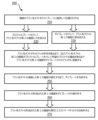
図2を参照すると、一実施形態では、本明細書に記載される又は他に想定される様々なブラシヘッドの実施形態及び実施態様のうちの1つ又は複数を製造するための製造方法200が示される。例えば、ブラシヘッド32は複数のブラシ毛タフト21を含むことができ、各タフト21が第1の端部23及び第2の端部25を有しており、各ブラシ毛タフトの第1の端部は、ブラシヘッド・アセンブリ10の可撓性のエラストマーマトリックス30内に保持される。一実施形態によれば、ブラシ毛の第1の端部23は、エラストマーマトリックス30との係合を高める、及び/又はブラシ毛タフトをエラストマーマトリックスから取り外すのに必要な力を増大させるような形状である。ブラシヘッド32の他の多くの実施形態及び構成が可能である。
Referring to FIG. 2, in one embodiment, a
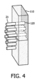
方法のステップ210において、各ブラシ毛タフト21の第1の端部23は、1つ又は複数のキャビティを含むタフトプレート内に位置付けされる。キャビティ又は複数のキャビティのそれぞれが、複数のブラシ毛タフトの少なくとも1つを受容するように構成される。キャビティは、単一のブラシ毛、単一のブラシ毛タフト、複数のブラシ毛タフト、又は全てのブラシ毛タフトを受容することができる。図3を参照すると、一実施形態では、複数のタフトキャビティ120を有するタフトプレート110の上面図が示されており、キャビティ120内にブラシ毛又はブラシ毛タフト21が挿入される。図4を参照すると、一実施形態では、タフトキャビティ120に挿入された状態の複数のブラシ毛又はブラシ毛タフト21を有するタフトプレート110の側面斜視図が示される。
In step 210 of the method, the
方法のステップ220において、力が、プロファイルプレート300によってブラシ毛タフト21の第2の端部25に加えられる。このステップの前に又はこのステップと同時に、ブラシ毛タフト21の第1の端部23は、ダイプレート400のキャビティ410と又はキャビティ410内で整列される。従って、好ましい実施形態では、タフトプレート110のキャビティ120及びダイプレート400のキャビティ410は、タフトプレートのキャビティを通過するタフトが、ダイプレートのキャビティと整列してキャビティ内に入ることができるように整列させる。
In
一実施形態によれば、プロファイルプレート300は、ブラシ毛タフトの所望のプロファイル構成に相補的な所定の形状又はプロファイルを含む。例えば、多くの歯ブラシのブラシ毛タフトは、ブラッシング効果を高めるように設計された輪郭のあるプロファイルを示す。プロファイルプレートは、ブラシ毛の所望の輪郭のあるプロファイルに相補的な構成を取り、それによって、プロファイルプレートがブラシ毛タフトの第2の端部25を押すか又は第2の端部25に押し付けられると、複数のブラシ毛タフトが所望の輪郭のあるプロファイルを取ることができる。輪郭のあるプロファイルは、曲線、直線、多層、及び他の多くのプロファイルを含む、任意の望ましいプロファイルであってよい。
According to one embodiment,
一実施形態によれば、プロファイルプレート300は、個々のブラシ毛又はブラシ毛タフトに圧力を加えるように構成された複数のピンを含む1つ又は複数のプレートを含むことができる。1つ又は複数のプロファイルプレートの実施形態によって力をブラシ毛に加えるための他の方法又はシステムが可能である。
According to one embodiment,
図5を参照すると、一実施形態では、タフトプレート・キャビティ120を介して複数のブラシ毛タフト21を位置決めするタフトプレート110の概略図が示される。タフトプレート110の片側には、ブラシ毛タフトの所望のプロファイル構成に相補的な所定の形状又はプロファイルを有するプロファイルプレート300がある。タフトプレートの反対側には、ブラシ毛タフト21の第1の端部23が挿入される複数のダイプレート・キャビティ410を含むダイプレート400がある。ダイプレート・キャビティ410は、ブラシ毛の溶融する第1の端部が取る形状を含むことができる。従って、ダイプレート・キャビティは、円形、正方形、三角形、長方形、楕円形、又は他の任意のサイズ又は形状であり得る。図6を参照すると、一実施形態では、複数の三角形のダイプレート・キャビティ410を含むダイプレート400が示される。ダイプレート・キャビティは、オプションで、リングを含むがこれに限定されない追加の構造を含むことができ、リングの周りに及び/又はそれを通って、ブラシ毛タフト21の第1の端部23が通過するか又は相互作用することができる。追加の構造及びブラシ毛タフトの第1の端部は、方法の下流のステップでブラシ毛の第1の端部が溶融するときに、融合するか、機械的に連結するか、又は別の望ましい構成を取ることができる。
Referring to FIG. 5, in one embodiment, a schematic diagram of a
方法のステップ230において、ダイプレート400は、複数のブラシ毛タフト21の第1の端部23に熱を加えて、各第1の端部をそれぞれのキャビティ内に少なくとも部分的に溶かし込んで整列させるのに十分な温度にする。例えば、ダイプレートは、外部熱源によって加熱することができ、或いは内部又は付属の熱源を含むことができる。加熱温度は、ブラシ毛が製造される材料、及び/又は第1の端部を溶融すべき速度、及び/又は1つ又は複数の他の要因に依存する。ブラシ毛タフトの第1の端部23が溶融すると、ブラシ毛タフト内のブラシ毛が融合し、第1の端部が挿入されたダイプレート・キャビティ410の形状にもなる。これは、ブラシ毛をダイプレート・キャビティに向かう方向に押すので、プロファイルプレート300によってブラシ毛タフトの第2の端部25に及ぼされる力によってさらに促進され、溶融する第1の端部がダイプレート・キャビティの形状を取るのを促進する。
In step 230 of the method, the
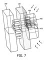
一実施形態によれば、ダイプレート・キャビティ410の1つ又は複数は、図7に示されるように、溶融した過剰なブラシ毛タフトを受容するように構成されたチャネル420を含む。プロファイルプレートがブラシ毛タフトの第2の端部25を押し、ダイプレートが第1の端部23を加熱すると、第1の端部が溶融し、ダイプレート・キャビティ410が満たされる。受容するようにサイズ決めされたキャビティよりも多くブラシ毛が溶融した場合に、溶融した過剰なブラシ毛は、チャネル420を介してキャビティから逃げることができる。
According to one embodiment, one or more of the
例えば、プロファイルプレートの力のためにブラシ毛の第2の端部によって取られる輪郭のあるプロファイルは、一部のブラシ毛が他のブラシ毛より短いことを必要とする可能性がある。こうして、より短いブラシ毛のためのダイプレート・キャビティは、必然的に、より長いブラシ毛のためのダイプレート・キャビティよりも多くの溶融したブラシ毛を受容する必要がある。ダイプレート・キャビティは、第2の端部の所望のプロファイル構成に少なくとも部分的に基づいて正確な量の溶融したブラシ毛を受容するように構成され得るが、他の実施形態では、ダイプレート・キャビティ410の1つ又は複数は、溶融した過剰なブラシ毛タフトを受容するように構成されたチャネル420を含み得る。このようにして、ダイプレートは、ブラシ毛の第2の端部の複数の異なるプロファイル、及び装置のための複数の異なるブラシ毛タフトの長さに適応することができる。
For example, the contoured profile taken by the second end of the bristles due to the force of the profile plate may require some bristles to be shorter than others. Thus, die plate cavities for shorter bristles necessarily need to receive more molten bristles than die plate cavities for longer bristles. Although the die plate cavities may be configured to receive a precise amount of melted bristles based at least in part on the desired profile configuration of the second end, in other embodiments, one or more of the
図7を参照すると、一実施形態では、ダイプレート400がブラシ毛タフトの第1の端部23を加熱するときに、タフトプレート110によって位置決めされた、ブラシ毛タフトの第2の端部25に力を及ぼすプロファイルプレート300の概略図が示される。図5と図7とを比較すると、例えば、ブラシ毛タフトの反対側の端部に力及び熱が加えられると、ブラシ毛タフトは短くなる。ダイプレート400は、溶融したブラシ毛タフトがその中に充填される複数のダイプレート・キャビティ410を含み、ダイプレート・キャビティの1つ又は複数は、溶融した過剰なブラシ毛タフトを受容するためのチャネル420を含む。
Referring to FIG. 7, in one embodiment, a schematic diagram of a
方法のステップ240において、プロファイルプレート300は、複数のブラシ毛タフト21の第2の端部25が所望のプロファイル構成を取るまで、力を加える。プロファイルプレートはまた、ブラシ毛がダイプレートとプロファイルプレートとの間で所定の長さを取るまで、力を加え得る。所望の長さ及び/又はプロファイル構成を取ると、プロファイルプレートは力の適用を停止し得、及び/又はダイプレートはブラシ毛の加熱を停止し得る。
In step 240 of the method, the
図8を参照すると、一実施形態では、ダイプレート400がブラシ毛タフト21の第1の端部23を加熱するときに、タフトプレート110によって位置決めされた、ブラシ毛タフト21の第2の端部25に力を及ぼすプロファイルプレート300の概略図が示される。プロファイルプレート300は、ブラシ毛タフト21が所定の所望の長さ及び/又は構成を取るまで、ブラシ毛タフト21の第2の端部25に力を及ぼしている。
Referring to FIG. 8, in one embodiment, a schematic diagram of a
方法のステップ250において、ダイプレート400は、ダイプレート・キャビティ410内に位置決めされた、複数のブラシ毛タフトの溶融した第1の端部が固化するまで、冷却される。例えば、ダイプレートは、エアジェット、液体冷却、又は他の方法によって冷却され得る。ダイプレート又は第1の端部は、所定の時間に亘って、又は第1の端部が十分に固化されると決定されるまで冷却してもよい。図9を参照すると、一実施形態では、プロファイルプレート300、タフトプレート110、及びダイプレート400の概略図が示され、ダイプレートが能動的又は受動的に冷却されて、溶融及び成形された第1の端部を冷却及び凝固させる。
In
方法のステップ260において、成形されたブラシ毛タフトは、排出又は他の方法によって、ダイプレートから取り外される。例えば、成形されたブラシ毛タフトは、タフトプレート110を引くことによって取り外され得る。代替的に又は追加的に、成形されたブラシ毛タフトは、突出しピン及び/又は空気圧を介して第1の端部23に力を及ぼすことによって取り外され得る。図10を参照すると、一実施形態では、第1の端部23がダイプレート400のダイキャビティの形状を取り、第2の端部25がプロファイルプレート300の輪郭又は構成を取る複数のブラシ毛タフトを有するタフトプレート110の概略図が示される。
In
方法のステップ270において、エラストマー材料が、ブラシネック42及びブラシ毛タフトの成形された第1の端部23の上に型成形されて、エラストマーマトリックス30を形成する。一実施形態によれば、エラストマーマトリックス30は、好ましくは可撓性の熱可塑性エラストマーから作製される。ブラシネック42は、ブラシ毛タフトの第1の端部23に対して位置付けすることができる。ブラシネック42は、例えば金型又は他の位置決め機構を使用して適切に位置付けすることができる。一実施形態によれば、硬質のブラシネック42は、エラストマーマトリックスのブラシネックへの融合を促進するように設計することができる。例えば、ブラシネックがスパンデックス(登録商標)、ポリメグ(商標)、又は同様のコポリマー等の材料から作製される場合に、これはエラストマーマトリックスのブラシネックへの融合を可能にし、それにより保持力を増大させる。さらに、この設計により、ブラシネック内のブラシ毛タフトの柔軟性が向上し、従ってブラシヘッド内の運動の追加の自由度が提供される。しかしながら、ブラシネック42のための他の多くの材料及び構成が可能である。
In method step 270 , an elastomeric material is molded over the
図11を参照すると、一実施形態では、溶融した形状を取る第1の端部23と、所望のプロファイル構成を取る第2の端部25とを有する複数のブラシ毛タフトを有するブラシ10の一部の概略図が示される。ブラシ毛の成形された第1の端部は、第1の端部及びブラシネック42の周りに形成されたエラストマーマトリックス30によって埋め込まれている。ブラシ毛の成形された端部は、エラストマーマトリックスが構成要素の周りに成形された後に、ブラシ毛タフトを完成したブラシヘッドに保持するのを高める。
Referring to FIG. 11, in one embodiment, a schematic illustration of a portion of a
一実施形態によれば、本明細書に記載又は他に想定される方法は、ブラシ毛タフトの第1の端部がダイプレート・キャビティの設計に従って任意の設計を取ることを可能にする。ブラシ毛タフトの溶融した形状の第1の端部は、一部がエラストマーマトリックスから外に延びている場合に、見えることがある。本明細書に記載又は他に想定される方法はまた、ブラシ毛タフトの第1の端部を、リング又は他の追加の構造なしに、エラストマーマトリックス又は他の保持機構に埋め込むことを可能にする。本明細書に記載又は他に想定される方法はまた、ブラシ毛タフトの第2の端部がプロファイルプレートの設計に従って任意の設計を取ることを可能にする。 According to one embodiment, methods described or otherwise contemplated herein allow the first end of the bristle tuft to take on any design according to the design of the die plate cavity. The fused shape first end of the bristle tuft may be visible if a portion extends out of the elastomeric matrix. Methods described or otherwise contemplated herein also allow the first end of the bristle tuft to be embedded in an elastomeric matrix or other retention mechanism without a ring or other additional structure. Methods described herein or otherwise envisioned also allow the second end of the bristle tuft to take on any design according to the design of the profile plate.
本明細書で規定及び使用される全ての規定は、辞書規定、参照により組み込まれる文書内の規定、及び/又は規定された用語の通常の意味を支配するものと理解すべきである。 All definitions defined and used herein shall be understood to govern dictionary definitions, definitions in documents incorporated by reference, and/or the ordinary meaning of the terms defined.
本明細書及び特許請求の範囲において使用される場合に、不定冠詞「1つの(a, an)」は、逆に明確に示されない限り、「少なくとも1つ」を意味すると理解すべきである。 As used in this specification and claims, the indefinite article "a, an" shall be understood to mean "at least one" unless clearly indicated to the contrary.
本明細書及び特許請求の範囲において使用される場合に、語句「及び/又は」は、そのように結合された要素、すなわち、ある場合には結合的に存在し、他の場合に分離的に存在する要素の「いずれか又は両方」を意味すると理解すべきである。「及び/又は」で列挙された複数の要素は、同じように、すなわちそのように結合された要素の「1つ又は複数」を意味すると解釈すべきである。「及び/又は」節によって具体的に特定された要素以外の他の要素が、具体的に特定された要素に関連するか否かに関係なく、オプションで存在する場合がある。 As used in the specification and claims, the phrase “and/or” should be understood to mean “either or both” of the elements so conjoined, i.e., present jointly in some cases and separately in other cases. Multiple elements listed with "and/or" should be construed to mean "one or more" of the elements in the same fashion, ie so conjoined. Other elements may optionally be present other than the elements specifically identified by the "and/or" clause, whether related or unrelated to those elements specifically identified.
本明細書及び特許請求の範囲において使用される場合に、「又は」は、上記で規定した「及び/又は」と同じ意味を有すると理解すべきである。例えば、リスト内のアイテムを区切る場合に、「又は」或いは「及び/又は」は、包括的、つまり複数の要素又は要素のリストの少なくとも1つを含むが、複数も含み、オプションで、列挙されていない追加のアイテムも含むものとして解釈されるものとする。「1つのみの~」又は「正に1つのみの~」等の明確に反対の用語が示される場合、又は特許請求の範囲で「~からなる」が使用される場合に、複数の要素又は要素のリストのうちの要素を1つだけ含めることを指す。一般に、本明細書で使用される場合に、「又は」という用語は、「どちらか」、「1つの~」、「~の1つのみ」、「~の正に1つ」等の排他的な用語が付いている場合にのみ、排他的な代替手段(つまり「一方、又は他方であり、両方ではない」)を示すものとして解釈されるものとする。 As used in the specification and claims, "or" should be understood to have the same meaning as "and/or" as defined above. For example, when delimiting items in a list, "or" or "and/or" shall be interpreted as inclusive, i.e., including at least one of a plurality of elements or a list of elements, but also including a plurality and optionally additional items not listed. Refers to the inclusion of only one element of a list of elements or elements when expressly opposed terms such as "only one" or "exactly one" are given, or when "consisting of" is used in a claim. In general, as used herein, the term “or” shall be construed as indicating exclusive alternatives (i.e., “one or the other, but not both”) only when accompanied by exclusive terms such as “either,” “one of,” “only one of,” “exactly one of.”
本明細書及び特許請求の範囲で使用される場合に、1つ又は複数の要素のリストに関する語句「少なくとも1つ」は、要素のリスト内の1つ又は複数の要素から選択される少なくとも1つの要素を意味すると理解すべきであるが、必ずしも要素のリスト内に具体的に列挙される全ての要素の少なくとも1つを含み、要素のリスト内の要素の組合せを排除するものではない。この規定はまた、「少なくとも1つ」という句が指す要素のリスト内で具体的に特定された要素以外の要素が、具体的に特定された要素に関連するか否かに関係なく、オプションで存在することを可能にする。 As used herein and in the claims, the phrase "at least one" in relation to a list of one or more elements should be understood to mean at least one element selected from one or more elements in the list of elements, but does not necessarily include at least one of all elements specifically recited in the list of elements and does not exclude combinations of elements in the list of elements. This provision also allows for the optional presence of elements other than the specifically identified elements in the list of elements referred to by the phrase "at least one," whether or not they are related to the specifically identified elements.
逆に明確に示されない限り、複数のステップ又は動作を含む本特許請求の範囲に記載される任意の方法において、方法のステップ又は動作の順序は、必ずしもこの方法のステップ又は動作が記載される順序に限定されないことも理解すべきである。 It should also be understood that, in any method recited in a claim that contains multiple steps or actions, the order of the method steps or actions is not necessarily limited to the order in which the method steps or actions are recited, unless explicitly indicated to the contrary.
特許請求の範囲及び上記の明細書において、「備える、有する、含む(comprising)」、「含む、有する(including)」、「運ぶ(carrying)」、「有する、含む(having)」、「含む(containing)」、「含む(involving)」、「保持する(holding)」、「~構成される(composed of)」等の全ての移行句は、オープンエンドとして、すなわち、目的語のものを含むがこれに限定されないことを意味すると理解すべきである。「~からなる(consisting of)」及び「本質的に~からなる(consisting essentially of)」という移行句のみが、それぞれクローズド又はセミクローズド移行句とする。 In the claims and the above specification, all transitional phrases such as "comprising," "including," "carrying," "having," "containing," "involving," "holding," "composed of," etc. are to be understood as open-ended, i.e., meant to include, but not be limited to, the object. Only the transitional phrases "consisting of" and "consisting essentially of" are closed or semi-closed transitional phrases, respectively.
本明細書ではいくつかの特許性を有する実施形態を説明及び図示してきたが、当業者は、機能を実行し、及び/又はその結果及び/又は本明細書に記載される利点を得るための様々な他の手段及び/又は構造を容易に想起するだろう。そのような変形及び/又は修正のそれぞれは、本明細書に記載される本発明の実施形態の範囲内であると見なされる。より一般的には、当業者は、本明細書に記載される全てのパラメータ、寸法、材料、及び構成が例示であることを意味し、実際のパラメータ、寸法、材料、及び/又は構成は、本発明の教示が使用される特定の1つ又は複数の用途に依存することを容易に理解するだろう。当業者は、本明細書に記載される特定の発明の実施形態に対する多くの同等物を認識し、又は通常の実験のみを使用してその同等物を確認することができるであろう。従って、前述した実施形態は例としてのみ提示され、添付の特許請求の範囲及びその均等物の範囲内で、本発明の実施形態は、具体的に説明し及び特許請求の範囲に記載された以外の方法で実施できることを理解されたい。本開示の特許性を有する実施形態は、本明細書に記載される個々の特徴、システム、物品、材料、キット、及び/又は方法を対象とする。さらに、2つ以上のそのような特徴、システム、物品、材料、キット、及び/又は方法の任意の組合せは、そのような特徴、システム、物品、材料、キット、及び/又は方法が互いに矛盾しない場合に、本開示の発明の範囲内に含まれる。 Although several patentable embodiments have been described and illustrated herein, those skilled in the art will readily conceive of various other means and/or structures for performing the functions and/or obtaining the results and/or advantages described herein. Each such variation and/or modification is considered within the scope of the embodiments of the invention described herein. More generally, those skilled in the art will readily appreciate that all parameters, dimensions, materials and configurations described herein are meant to be exemplary and the actual parameters, dimensions, materials and/or configurations will depend on the particular application or applications in which the teachings of the present invention are used. Those skilled in the art will recognize, or be able to ascertain using no more than routine experimentation, many equivalents to the specific inventive embodiments described herein. Accordingly, it is to be understood that the above-described embodiments are presented by way of example only, and that within the scope of the appended claims and equivalents thereof, embodiments of the invention may be practiced otherwise than as specifically described and claimed. Patentable embodiments of the present disclosure are directed to each individual feature, system, article, material, kit, and/or method described herein. Moreover, any combination of two or more of such features, systems, articles, materials, kits, and/or methods is included within the scope of the present disclosure, provided such features, systems, articles, materials, kits, and/or methods are not inconsistent with each other.
Claims (13)
複数のブラシ毛タフトのそれぞれの第1の端部をタフトプレート内に位置付けするステップであって、前記タフトプレートは複数のキャビティを含み、各キャビティが前記複数のブラシ毛タフトの少なくとも1つを受容するように構成される、位置付けするステップと、
プロファイルプレートを介して、前記複数のブラシ毛タフトのそれぞれの第2の端部に力を加えるステップであって、前記プロファイルプレートは、前記ブラシ毛タフトの所望のプロファイル構成に相補的な所定の形状を含む、力を加えるステップと、
前記ブラシ毛タフトの複数の前記第1の端部の少なくとも1つを受容するように構成された少なくとも1つのキャビティを含むダイプレートを介して、前記複数のブラシ毛タフトの前記第1の端部のそれぞれに熱を加えて、前記第1の端部のそれぞれを前記キャビティ内に少なくとも部分的に溶かし込むのに十分な温度にするステップであって、前記複数のブラシ毛タフトの各第1の端部が前記キャビティの形状を取る、温度にするステップと、を含む、
製造方法。 A manufacturing method for manufacturing a brush head, the manufacturing method comprising:
positioning a first end of each of a plurality of bristle tufts within a tuft plate, said tuft plate including a plurality of cavities, each cavity configured to receive at least one of said plurality of bristle tufts;
applying a force to a second end of each of the plurality of bristle tufts via a profile plate, the profile plate including a predetermined shape complementary to a desired profile configuration of the bristle tufts;
applying heat to each of the first ends of the plurality of bristle tufts through a die plate including at least one cavity configured to receive at least one of the first ends of the plurality of bristle tufts to a temperature sufficient to at least partially melt each of the first ends into the cavities, wherein each first end of the plurality of bristle tufts assumes the shape of the cavity;
Production method.
複数のタフトプレート・キャビティを含むタフトプレートであって、各キャビティが、ブラシ毛又はブラシ毛タフトを受容するように構成される、タフトプレートと、
前記ブラシ毛タフトの所望の最終的なプロファイル構成に相補的な所定の形状を含むプロファイルプレートであって、前記タフトプレート内に位置付けされたブラシ毛又はブラシ毛タフトの第2の端部に力を加えるように構成されるプロファイルプレートと、
前記タフトプレート内に位置付けされたブラシ毛又はブラシ毛タフトの第1の端部を受容するように構成された少なくとも1つのダイプレート・キャビティを含むダイプレートであって、前記ブラシ毛又はブラシ毛タフトの前記第1の端部を加熱して、前記第1の端部のそれぞれを前記キャビティ内に少なくとも部分的に溶かし込むのに十分な温度にするように構成されるダイプレートと、を含む、
システム。 A system for manufacturing a brush head, the system comprising:
a tuft plate including a plurality of tuft plate cavities, each cavity configured to receive a bristle or bristle tuft;
a profile plate comprising a predetermined shape complementary to a desired final profile configuration of said bristle tuft, said profile plate being configured to apply a force to a second end of a bristle or bristle tuft positioned within said tuft plate;
a die plate comprising at least one die plate cavity configured to receive first ends of bristles or bristle tufts positioned within the tuft plate, the die plate configured to heat the first ends of the bristles or bristle tufts to a temperature sufficient to at least partially melt each of the first ends into the cavities;
system.
Applications Claiming Priority (3)
| Application Number | Priority Date | Filing Date | Title |
|---|---|---|---|
| US201762597513P | 2017-12-12 | 2017-12-12 | |
| US62/597,513 | 2017-12-12 | ||
| PCT/EP2018/083396 WO2019115279A1 (en) | 2017-12-12 | 2018-12-04 | Brush head assembly and methods of manufacture |
Publications (2)
| Publication Number | Publication Date |
|---|---|
| JP2021505305A JP2021505305A (en) | 2021-02-18 |
| JP7315552B2 true JP7315552B2 (en) | 2023-07-26 |
Family
ID=64899241
Family Applications (1)
| Application Number | Title | Priority Date | Filing Date |
|---|---|---|---|
| JP2020531741A Active JP7315552B2 (en) | 2017-12-12 | 2018-12-04 | Brush head assembly and method of manufacturing same |
Country Status (5)
| Country | Link |
|---|---|
| US (1) | US11723453B2 (en) |
| EP (1) | EP3723547A1 (en) |
| JP (1) | JP7315552B2 (en) |
| CN (1) | CN111712158B (en) |
| WO (1) | WO2019115279A1 (en) |
Families Citing this family (2)
| Publication number | Priority date | Publication date | Assignee | Title |
|---|---|---|---|---|
| USD937583S1 (en) * | 2021-02-09 | 2021-12-07 | Show Charm Precision Electronics (Shenzhen) Co., LTD | Combination electric toothbrush and travel case |
| USD1121969S1 (en) | 2024-08-06 | 2026-04-14 | Oralic Supplies, Inc. | Toothbrush head |
Citations (8)
| Publication number | Priority date | Publication date | Assignee | Title |
|---|---|---|---|---|
| JP2002079551A (en) | 2000-06-29 | 2002-03-19 | Toyo Tire & Rubber Co Ltd | Mold for molding with cylindrical core |
| JP2003245970A (en) | 2002-02-27 | 2003-09-02 | Shibaura Mechatronics Corp | Sheet forming method and apparatus |
| WO2006082799A1 (en) | 2005-02-02 | 2006-08-10 | Sunstar Inc. | Toothbrush |
| JP2012096421A (en) | 2010-11-01 | 2012-05-24 | Daisen Co Ltd | Molding method and apparatus of foam-molded article |
| US20130241267A1 (en) | 2012-03-19 | 2013-09-19 | Zahoransky Ag | Apparatus for the production of brushes or bristled-wares and brush or bristled-wares |
| JP2015131441A (en) | 2014-01-14 | 2015-07-23 | 有限会社ベストテクニカル | Mold device for injection molding |
| JP2017508542A (en) | 2014-03-25 | 2017-03-30 | コーニンクレッカ フィリップス エヌ ヴェKoninklijke Philips N.V. | Brush head assembly and manufacturing method |
| JP2017063811A (en) | 2015-09-28 | 2017-04-06 | 三菱鉛筆株式会社 | Brush and brush manufacturing method |
Family Cites Families (16)
| Publication number | Priority date | Publication date | Assignee | Title |
|---|---|---|---|---|
| JPH0217848Y2 (en) | 1986-12-18 | 1990-05-18 | ||
| DE4029610C2 (en) * | 1990-09-19 | 2002-06-13 | Zahoransky Anton Gmbh & Co | Method for connecting bundles of bristles to a brush body or the like and brush manufacturing machine |
| JPH0687128A (en) * | 1992-09-08 | 1994-03-29 | Iseki & Co Ltd | Resin injection molding method |
| JPH0956476A (en) | 1995-08-29 | 1997-03-04 | Lion Corp | Brush and manufacturing method thereof |
| EP1136016A1 (en) * | 2000-03-21 | 2001-09-26 | G.B. Boucherie, N.V. | Method and device for melting ends of bristles |
| JP2006087128A (en) | 2005-09-26 | 2006-03-30 | Nec Corp | Folding-type portable telephone |
| DE602009000006D1 (en) * | 2008-01-10 | 2010-04-08 | Gb Boucherie Nv | Stamp for pressing fiber bundles |
| DE102008039778A1 (en) * | 2008-08-26 | 2010-03-04 | Firma G.B. Boucherie N.V. | Method for producing brushes, in particular toothbrushes |
| DE102009058608B4 (en) | 2009-12-17 | 2023-02-02 | Gb Boucherie Nv | Method of connecting brush head plates to brush bodies |
| US8308246B2 (en) | 2010-03-19 | 2012-11-13 | Chung Tae Sang | Method for manufacturing toothbrush and toothbrush manufactured by the method |
| EP2377424B1 (en) | 2010-04-13 | 2013-10-23 | GB Boucherie NV | Device and method for manufacturing brushes |
| JP2012000148A (en) * | 2010-06-14 | 2012-01-05 | Panasonic Electric Works Co Ltd | Brush body and toothbrush including the same |
| EP2534973B1 (en) | 2011-06-15 | 2015-04-08 | Braun GmbH | Method and tool for producing a brush head |
| RU2711868C2 (en) | 2015-05-14 | 2020-01-23 | Конинклейке Филипс Н.В. | Brush cleaning head assembly and methods for manufacture thereof |
| RU2717582C2 (en) * | 2015-05-14 | 2020-03-24 | Конинклейке Филипс Н.В. | Brush head unit and methods for manufacture thereof |
| EP3294091B1 (en) * | 2015-05-14 | 2022-04-06 | Koninklijke Philips N.V. | Brush head assembly |
-
2018
- 2018-12-04 JP JP2020531741A patent/JP7315552B2/en active Active
- 2018-12-04 CN CN201880089131.8A patent/CN111712158B/en active Active
- 2018-12-04 US US16/771,284 patent/US11723453B2/en active Active
- 2018-12-04 WO PCT/EP2018/083396 patent/WO2019115279A1/en not_active Ceased
- 2018-12-04 EP EP18826195.2A patent/EP3723547A1/en active Pending
Patent Citations (8)
| Publication number | Priority date | Publication date | Assignee | Title |
|---|---|---|---|---|
| JP2002079551A (en) | 2000-06-29 | 2002-03-19 | Toyo Tire & Rubber Co Ltd | Mold for molding with cylindrical core |
| JP2003245970A (en) | 2002-02-27 | 2003-09-02 | Shibaura Mechatronics Corp | Sheet forming method and apparatus |
| WO2006082799A1 (en) | 2005-02-02 | 2006-08-10 | Sunstar Inc. | Toothbrush |
| JP2012096421A (en) | 2010-11-01 | 2012-05-24 | Daisen Co Ltd | Molding method and apparatus of foam-molded article |
| US20130241267A1 (en) | 2012-03-19 | 2013-09-19 | Zahoransky Ag | Apparatus for the production of brushes or bristled-wares and brush or bristled-wares |
| JP2015131441A (en) | 2014-01-14 | 2015-07-23 | 有限会社ベストテクニカル | Mold device for injection molding |
| JP2017508542A (en) | 2014-03-25 | 2017-03-30 | コーニンクレッカ フィリップス エヌ ヴェKoninklijke Philips N.V. | Brush head assembly and manufacturing method |
| JP2017063811A (en) | 2015-09-28 | 2017-04-06 | 三菱鉛筆株式会社 | Brush and brush manufacturing method |
Also Published As
| Publication number | Publication date |
|---|---|
| CN111712158B (en) | 2023-04-14 |
| WO2019115279A1 (en) | 2019-06-20 |
| RU2020123090A3 (en) | 2022-04-14 |
| RU2020123090A (en) | 2022-01-14 |
| JP2021505305A (en) | 2021-02-18 |
| US11723453B2 (en) | 2023-08-15 |
| US20200375349A1 (en) | 2020-12-03 |
| CN111712158A (en) | 2020-09-25 |
| EP3723547A1 (en) | 2020-10-21 |
Similar Documents
| Publication | Publication Date | Title |
|---|---|---|
| JP6629341B2 (en) | Brush head assembly and manufacturing method | |
| EP3122209B1 (en) | Brush head arrangements | |
| JP6892388B2 (en) | Brush head assembly and its manufacturing method | |
| JP2012152928A (en) | Method of molding interdental brush and molding device | |
| JP7632866B2 (en) | Brush head configuration | |
| JP7315552B2 (en) | Brush head assembly and method of manufacturing same | |
| RU2781101C2 (en) | Brush head node and its manufacturing methods | |
| WO2019158370A1 (en) | Brush head arrangements and manufacturing method |
Legal Events
| Date | Code | Title | Description |
|---|---|---|---|
| A621 | Written request for application examination |
Free format text: JAPANESE INTERMEDIATE CODE: A621 Effective date: 20211201 |
|
| A977 | Report on retrieval |
Free format text: JAPANESE INTERMEDIATE CODE: A971007 Effective date: 20221109 |
|
| A131 | Notification of reasons for refusal |
Free format text: JAPANESE INTERMEDIATE CODE: A131 Effective date: 20221206 |
|
| A521 | Request for written amendment filed |
Free format text: JAPANESE INTERMEDIATE CODE: A523 Effective date: 20230222 |
|
| TRDD | Decision of grant or rejection written | ||
| A01 | Written decision to grant a patent or to grant a registration (utility model) |
Free format text: JAPANESE INTERMEDIATE CODE: A01 Effective date: 20230620 |
|
| A61 | First payment of annual fees (during grant procedure) |
Free format text: JAPANESE INTERMEDIATE CODE: A61 Effective date: 20230713 |
|
| R150 | Certificate of patent or registration of utility model |
Ref document number: 7315552 Country of ref document: JP Free format text: JAPANESE INTERMEDIATE CODE: R150 |