RU2717582C2 - Brush head unit and methods for manufacture thereof - Google Patents
Brush head unit and methods for manufacture thereof Download PDFInfo
- Publication number
- RU2717582C2 RU2717582C2 RU2017143568A RU2017143568A RU2717582C2 RU 2717582 C2 RU2717582 C2 RU 2717582C2 RU 2017143568 A RU2017143568 A RU 2017143568A RU 2017143568 A RU2017143568 A RU 2017143568A RU 2717582 C2 RU2717582 C2 RU 2717582C2
- Authority
- RU
- Russia
- Prior art keywords
- proximal end
- brush
- head
- neck
- retaining rings
- Prior art date
Links
Images


Classifications
-
- A—HUMAN NECESSITIES
- A46—BRUSHWARE
- A46B—BRUSHES
- A46B3/00—Brushes characterised by the way in which the bristles are fixed or joined in or on the brush body or carrier
- A46B3/08—Brushes characterised by the way in which the bristles are fixed or joined in or on the brush body or carrier by clamping
- A46B3/10—Brushes characterised by the way in which the bristles are fixed or joined in or on the brush body or carrier by clamping into rings or the like
-
- A—HUMAN NECESSITIES
- A46—BRUSHWARE
- A46B—BRUSHES
- A46B3/00—Brushes characterised by the way in which the bristles are fixed or joined in or on the brush body or carrier
- A46B3/06—Brushes characterised by the way in which the bristles are fixed or joined in or on the brush body or carrier by welding together bristles made of metal wires or plastic materials
-
- A—HUMAN NECESSITIES
- A46—BRUSHWARE
- A46B—BRUSHES
- A46B3/00—Brushes characterised by the way in which the bristles are fixed or joined in or on the brush body or carrier
- A46B3/20—Brushes characterised by the way in which the bristles are fixed or joined in or on the brush body or carrier the bristles being fixed or joined in rubber bodies, e.g. in soft rubber
-
- A—HUMAN NECESSITIES
- A46—BRUSHWARE
- A46B—BRUSHES
- A46B7/00—Bristle carriers arranged in the brush body
-
- A—HUMAN NECESSITIES
- A46—BRUSHWARE
- A46B—BRUSHES
- A46B9/00—Arrangements of the bristles in the brush body
- A46B9/08—Supports or guides for bristles
-
- A—HUMAN NECESSITIES
- A46—BRUSHWARE
- A46B—BRUSHES
- A46B9/00—Arrangements of the bristles in the brush body
- A46B9/08—Supports or guides for bristles
- A46B9/12—Non-adjustable supports
-
- A—HUMAN NECESSITIES
- A46—BRUSHWARE
- A46D—MANUFACTURE OF BRUSHES
- A46D3/00—Preparing, i.e. Manufacturing brush bodies
- A46D3/04—Machines for inserting or fixing bristles in bodies
- A46D3/045—Machines for inserting or fixing bristles in bodies for fixing bristles by fusing or gluing to a body
-
- A—HUMAN NECESSITIES
- A46—BRUSHWARE
- A46D—MANUFACTURE OF BRUSHES
- A46D3/00—Preparing, i.e. Manufacturing brush bodies
- A46D3/04—Machines for inserting or fixing bristles in bodies
- A46D3/047—Machines for inserting or fixing bristles in bodies for clamping or gluing bristles into rings, e.g. paint brushes, brooms
-
- A—HUMAN NECESSITIES
- A61—MEDICAL OR VETERINARY SCIENCE; HYGIENE
- A61C—DENTISTRY; APPARATUS OR METHODS FOR ORAL OR DENTAL HYGIENE
- A61C17/00—Devices for cleaning, polishing, rinsing or drying teeth, teeth cavities or prostheses; Saliva removers; Dental appliances for receiving spittle
- A61C17/16—Power-driven cleaning or polishing devices
- A61C17/22—Power-driven cleaning or polishing devices with brushes, cushions, cups, or the like
Abstract
Description
Область техники, к которой относится изобретениеFIELD OF THE INVENTION
[0001] Настоящее раскрытие направлено в целом на блок головки щетки, имеющей щетиночные пучки, удерживаемые в эластомерной матрице, а также к способам изготовления блока головки щетки.[0001] The present disclosure is directed generally to a brush head block having bristle tufts held in an elastomeric matrix, as well as to methods for manufacturing a brush head block.
Предшествующий уровень техникиState of the art
[0002] Считается, что заболевания пародонта представляют собой инфекционные заболевания, вызванные бактериями, присутствующими в зубной бляшке. Чистка зубов является эффективным способом удаления зубной бляшки с зубов. Электрические зубные щетки могут улучшить удаление зубной бляшки. Такие электрические зубные щетки имеют набор щетинок, прикрепленных к головке щетки, которая приводится в действие приводом, что приводит к очистке щетинками зубных поверхностей.[0002] It is believed that periodontal disease is an infectious disease caused by bacteria present in a dental plaque. Brushing your teeth is an effective way to remove plaque from your teeth. Electric toothbrushes can improve tooth plaque removal. Such electric toothbrushes have a set of bristles attached to the brush head, which is driven by a drive, which leads to brushing of the tooth surfaces.
[0003] Головки щеток, как ручных, так и электрических зубных щеток, содержат щетинки, которые используются для очистки зубов, языка и щек. В некоторых зубных щетках щетинки собраны в щетиночные пучки, заключенные в удерживающие кольца. Удерживающие кольца служат для фиксации щетиночных пучков в головке щетки и часто имеют полую кольцеобразную форму с внутренним и наружным кольцеобразным периметром. При изготовлении щетиночные пучки вставляются в полое внутреннее пространство удерживающего кольца, и щетинки в удерживающем кольце затем сплавляются вместе с использованием нагревания с образованием головки, которая не может быть вытянута через удерживающее кольцо.[0003] The heads of brushes, both manual and electric toothbrushes, contain bristles that are used to clean teeth, tongue and cheeks. In some toothbrushes, the bristles are collected in bristle tufts enclosed in retaining rings. The retaining rings serve to fix the bristle tufts in the brush head and often have a hollow annular shape with an inner and outer annular perimeter. In the manufacture, the bristle tufts are inserted into the hollow interior of the holding ring, and the bristles in the holding ring are then fused together using heat to form a head that cannot be pulled out through the holding ring.
[0004] Однако часто удерживающие кольца непрочно фиксированы в головке щетки. В результате кольцо и щетиночный пучок могут болтаться или расшатываться в головке щетки, и щетинки могут не всегда располагаться под углом, оптимальным для чистки. А потому при динамических состояниях движения, вызванных, например, работой электрической зубной щетки, конструкция щетиночного пучка может испытывать более сильные напряжения при динамическом движении, что может привести к отделению. Кроме того, процесс собирания щетинок в пучки в удерживающих кольцах и дальнейшее охлаждение или остывания материала головки щетки для фиксации пучков на месте может быть длительным и дорогим.[0004] However, often the retaining rings are loosely fixed to the brush head. As a result, the ring and the bristle tuft may dangle or loosen in the brush head, and the bristles may not always be at an angle that is optimal for cleaning. Therefore, under dynamic states of motion, caused, for example, by the operation of an electric toothbrush, the design of the bristle bundle may experience more intense stresses during dynamic movement, which can lead to separation. In addition, the process of collecting the bristles into bundles in the retaining rings and further cooling or cooling the brush head material to fix the tufts in place can be lengthy and expensive.
[0005] Соответственно, в данной области техники существует потребность в блоках головки щетки и способах его изготовления, которые постоянно и эффективно удерживают щетиночные пучки в головке щетки.[0005] Accordingly, in the art there is a need for brush head blocks and methods for its manufacture that continuously and efficiently hold bristle tufts in the brush head.
Сущность изобретенияSUMMARY OF THE INVENTION
[0006] Настоящее раскрытие направлено на изобретательские способы изготовления головки щетки, имеющей фиксированные щетиночные пучки. Различные варианты осуществления и воплощения, приведенные в настоящем документе, направлены на способы изготовления, в которых щетиночные пучки фиксируются удерживающими кольцами и затем вделываются в эластомерную матрицу, что приводит к готовой головке щетки. При использовании различных вариантов осуществления и воплощений, приведенных в настоящем документе, значительно увеличивается рентабельность и эффективность изготовления головок щетки с фиксированными щетиночными пучками. Например, в некоторых вариантах осуществления способ изготовления обеспечивает головку щетки, в которой головка щетиночного пучка вделана в эластомерную матрицу и расположена на расстоянии от удерживающего кольца. В результате в окончательной головке щетки эластомерная матрица расположена между удерживающим кольцом и пучковым кольцом. Когда щетиночный пучок вытягивается, некоторая часть силы распределяется по окружающей эластомерной матрице, расположенной между головкой щетиночного пучка и удерживающим кольцом. Это обеспечивает большую гибкость перемещения пучков, и также, за счет уменьшения давления, уменьшается вероятность вырывания удерживающей головки через удерживающее кольцо, вызывая преждевременный выход из строя головки щетки из-за потери щетиночного пучка.[0006] The present disclosure is directed to inventive methods for manufacturing a brush head having fixed bristle tufts. Various embodiments and embodiments described herein are directed to manufacturing methods in which the bristle tufts are fixed by retaining rings and then embedded into an elastomeric matrix, resulting in a finished brush head. By using the various embodiments and embodiments provided herein, the cost-effectiveness and manufacturing efficiency of brush heads with fixed bristle tufts is significantly increased. For example, in some embodiments, the manufacturing method provides a brush head in which a bristle tuft head is embedded in an elastomeric matrix and spaced apart from the retaining ring. As a result, in the final brush head, the elastomeric matrix is located between the retaining ring and the beam ring. When the bristle bundle is stretched, some of the force is distributed over the surrounding elastomeric matrix located between the head of the bristle bundle and the holding ring. This provides greater flexibility in the movement of the tufts, and also, by reducing the pressure, the probability of tearing the holding head through the holding ring is reduced, causing premature failure of the brush head due to loss of the bristle tuft.
[0007] В целом в одном аспекте обеспечивается головка щетки. Головка щетки включает в себя: твердую щеточную часть шейки; множество щетиночных пучков, каждый из которых содержит множество щетиночных нитей, имеющих свободный конец и проксимальный конец, при этом проксимальный конец содержит головной участок проксимального конца; множество удерживающих колец, каждое из которых выполнено с возможностью вмещения проксимального конца по меньшей мере одного из множества щетиночных пучков; эластомерную матрицу, соединенную с по меньшей мере участком твердой щеточной части шейки, множеством удерживающих колец и проксимальным концом множества щетиночных пучков, при этом головной участок проксимального конца каждого из множества щетиночных пучков выполнен с возможностью наличия промежутка между головным участком проксимального конца и соответствующим удерживающим кольцом.[0007] In general, in one aspect, a brush head is provided. The brush head includes: a hard brush part of the neck; a plurality of bristle tufts, each of which contains a plurality of bristle filaments having a free end and a proximal end, wherein the proximal end contains a head portion of the proximal end; a plurality of retaining rings, each of which is configured to receive a proximal end of at least one of the plurality of bristle tufts; an elastomeric matrix connected to at least a portion of the solid brush portion of the neck, a plurality of retaining rings and a proximal end of the plurality of bristle tufts, wherein the head portion of the proximal end of each of the plurality of bristle tufts is configured to have a gap between the head portion of the proximal end and the corresponding retaining ring.
[0008] Согласно варианту осуществления множество удерживающих колец по меньшей мере частично взаимосоединены сетью решетчатых связей.[0008] According to an embodiment, the plurality of retaining rings are at least partially interconnected by a network of trellised bonds.
[0009] Согласно варианту осуществления сеть решетчатых связей по меньшей мере частично заключена в эластомерную матрицу.[0009] According to an embodiment, the network of lattice bonds is at least partially enclosed in an elastomeric matrix.
[0010] Согласно варианту осуществления эластомерная матрица полностью окружает твердую щеточную часть шейки и головной участок проксимального конца каждого из множества щетиночных пучков.[0010] According to an embodiment, the elastomeric matrix completely surrounds the solid brush portion of the neck and the head portion of the proximal end of each of the plurality of bristle tufts.
[0011] Согласно варианту осуществления щетиночные нити изготовлены из нейлона, а эластомерная матрица содержит гибкий термопластический эластомер.[0011] According to an embodiment, the bristle threads are made of nylon and the elastomeric matrix comprises a flexible thermoplastic elastomer.
[0012] Согласно одному аспекту, обеспечивается способ изготовления головки щетки. Способ включает в себя этапы, на которых: обеспечивают множество удерживающих колец и множество щетиночных пучков, при этом каждый из множества щетиночных пучков содержит множество щетиночных нитей, имеющих свободный конец и проксимальный конец; вставляют по меньшей мере один из множества щетиночных пучков в соответствующее одно из множества удерживающих колец; воздействуют нагреванием на каждый из проксимальных концов щетиночных пучков при температуре и расстоянии, достаточных для по меньшей мере частичного расплавления проксимального конца щетиночного пучка для создания головного участка проксимального конца; создают первый промежуток между каждым из головных участков проксимального конца и соответствующим удерживающим кольцом; позиционируют щеточную часть шейки относительно головных участков проксимального конца, при этом позиционирование щеточной части шейки задает второй промежуток относительно головных участков проксимального конца; и вводят термопластический эластомер для создания эластомерной матрицы, которая по меньшей мере частично окружает щеточную часть шейки, множество удерживающих колец, головные участки проксимального конца, при этом эластомерная матрица заполняет первый и второй промежутки.[0012] According to one aspect, a method for manufacturing a brush head is provided. The method includes the steps of: providing a plurality of retaining rings and a plurality of bristle tufts, each of the plurality of bristle tufts comprising a plurality of bristle filaments having a free end and a proximal end; at least one of the plurality of bristle tufts is inserted into one of the plurality of retaining rings; acting on each of the proximal ends of the bristle bundles by heating at a temperature and distance sufficient to at least partially melt the proximal end of the bristle bundle to create a head portion of the proximal end; create a first gap between each of the head sections of the proximal end and the corresponding retaining ring; positioning the brush portion of the neck relative to the head portions of the proximal end, while positioning the brush portion of the neck defines a second gap relative to the head portions of the proximal end; and a thermoplastic elastomer is introduced to create an elastomeric matrix that at least partially surrounds the brush portion of the neck, the plurality of retaining rings, head portions of the proximal end, wherein the elastomeric matrix fills the first and second gaps.
[0013] Согласно варианту осуществления этап создания содержит подэтап, на котором прилагают силу к свободному концу каждого из множества щетиночных пучков.[0013] According to an embodiment, the creating step comprises a sub-step in which a force is applied to the free end of each of the plurality of bristle tufts.
[0014] Согласно варианту осуществления этап создания содержит подэтап, на котором используют направляющую для создания первого промежутка.[0014] According to an embodiment, the creating step comprises a sub-step in which a guide is used to create the first gap.
[0015] Согласно одному аспекту, обеспечивается блок головки щетки для электрической зубной щетки. Блок головки щетки включает в себя шейку и головку щетки, причем указанная головка щетки содержит: множество удерживающих колец, каждое из которых содержит щетиночный пучок, при этом каждый щетиночный пучок содержит головной участок проксимального конца на своем проксимальном конце, причем головной участок проксимального конца отделен от соответствующего одного из удерживающих колец первым промежутком; щеточную часть шейки, позиционированную относительно множества головных участков проксимального конца для создания второго промежутка; эластомерную матрицу, окружающую по меньшей мере участок множества удерживающих колец, головные участки проксимального конца и щеточную часть шейки, при этом эластомерная матрица заполняет первый и второй промежутки.[0015] According to one aspect, a brush head unit for an electric toothbrush is provided. The brush head block includes a neck and a brush head, said brush head comprising: a plurality of retaining rings, each of which contains a bristle bundle, each bristle bundle comprising a head portion of the proximal end at its proximal end, the head portion of the proximal end being separated from the corresponding one of the retaining rings in the first space; a brush portion of the neck positioned relative to the plurality of head portions of the proximal end to create a second gap; an elastomeric matrix surrounding at least a portion of the plurality of retaining rings, head portions of the proximal end and a brush portion of the neck, while the elastomeric matrix fills the first and second gaps.
[0016] Следует принимать во внимание, что все комбинации вышеупомянутых концепций и дополнительные концепции, рассмотренные ниже подробно (при условии, что такие концепции не являются взаимно несовместимыми), рассматриваются как часть объекта изобретения, раскрытого в настоящем документе. В частности, предполагается, что все сочетания заявленных объектов, упомянутых в конце настоящего раскрытия, являются частью объекта изобретения, раскрытого в настоящем документе.[0016] It should be appreciated that all combinations of the above concepts and additional concepts discussed in detail below (provided that such concepts are not mutually incompatible) are considered as part of the subject matter disclosed herein. In particular, it is assumed that all combinations of the claimed objects mentioned at the end of this disclosure are part of the subject matter disclosed herein.
[0017] Эти и другие аспекты изобретения станут очевидны из вариантов осуществления, описанных здесь и далее, и объясненных со ссылкой на эти варианты осуществления.[0017] These and other aspects of the invention will become apparent from the embodiments described hereinafter and explained with reference to these embodiments.
Краткое описание чертежейBrief Description of the Drawings
[0018] На чертежах подобные номера ссылочных позиций относятся в целом к одним и тем же частям на различных изображениях. Также, чертежи необязательно выполнены в масштабе, вместо этого упор сделан на иллюстрирование принципов изобретения.[0018] In the drawings, like reference numerals generally refer to the same parts in different images. Also, the drawings are not necessarily made to scale, instead, emphasis is placed on illustrating the principles of the invention.
[0019] Фиг.1 - схематическое изображение вида сбоку блока головки щетки согласно варианту осуществления.[0019] FIG. 1 is a schematic side view of a brush head unit according to an embodiment.
[0020] Фиг.2 - схематическое изображение участка блока головки щетки согласно варианту осуществления.[0020] Figure 2 is a schematic illustration of a portion of a brush head block according to an embodiment.
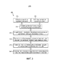
[0021] Фиг.3 - блок-схема способа изготовления блока головки щетки, имеющего щетиночные пучки, удерживаемые в эластомерной матрице согласно варианту осуществления.[0021] FIG. 3 is a flowchart of a method of manufacturing a brush head unit having bristle tufts held in an elastomeric matrix according to an embodiment.
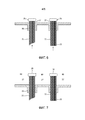
[0022] Фиг.4 - схематическое изображение головки щетки при изготовлении, согласно варианту осуществления.[0022] FIG. 4 is a schematic illustration of a brush head during manufacture, according to an embodiment.
[0023] Фиг.5 - схематическое изображение головки щетки при изготовлении, согласно варианту осуществления.[0023] FIG. 5 is a schematic illustration of a brush head during manufacture, according to an embodiment.
[0024] Фиг.6 - схематическое изображение головки щетки при изготовлении, согласно варианту осуществления.[0024] FIG. 6 is a schematic illustration of a brush head during manufacture, according to an embodiment.
[0025] Фиг.7 - схематическое изображение головки щетки при изготовлении, согласно варианту осуществления.[0025] FIG. 7 is a schematic illustration of a brush head during manufacture, according to an embodiment.
[0026] Фиг.8 - схематическое изображение головки щетки при изготовлении, согласно варианту осуществления.[0026] FIG. 8 is a schematic illustration of a brush head during manufacture, according to an embodiment.
[0027] Фиг.9 - схематическое изображение головки щетки при изготовлении, согласно варианту осуществления.[0027] FIG. 9 is a schematic illustration of a brush head during manufacture, according to an embodiment.
[0028] Фиг.10 - схематическое изображение головки щетки при изготовлении, согласно варианту осуществления.[0028] FIG. 10 is a schematic illustration of a brush head during manufacture, according to an embodiment.
Подробное описание вариантов осуществленияDetailed Description of Embodiments
[0029] Настоящее раскрытие описывает различные варианты осуществления блока головки щетки, имеющего щетиночные пучки, удерживаемые в эластомерной матрице, и способы их изготовления. В более общем смысле заявители обнаружили и оценили, что было бы выгодно обеспечить головку щетки, выполненную с щетинками, вделанными в эластомерную матрицу, для улучшения удержания щетинок. Вделывание щетиночных пучков в эластомерную матрицу так, что головка щетиночного пучка находится на расстоянии от удерживающих колец, обеспечивает более сильное удержание пучков, что является полезным для функции головки щетки, особенно в электрических устройствах для чистки зубов. Конкретная цель использования некоторых вариантов осуществления настоящего раскрытия состоит в возможности эффективного изготовления головок щетки, имеющих улучшенное удержание щетиночного пучка и улучшенную гибкость щетиночного пучка.[0029] The present disclosure describes various embodiments of a brush head block having bristle tufts held in an elastomeric matrix, and methods for their manufacture. More generally, applicants have discovered and appreciated that it would be advantageous to provide a brush head made with bristles embedded in an elastomeric matrix to improve bristle retention. The insertion of the bristle tufts into the elastomeric matrix so that the bristle tuft head is at a distance from the retaining rings provides a stronger tuft retention, which is useful for the function of the brush head, especially in electric devices for brushing teeth. The specific purpose of using some embodiments of the present disclosure is to efficiently manufacture brush heads having improved bristle tuft retention and improved bristle tuft flexibility.
[0030] Головки щетки, раскрытые и описанные в настоящем документе, могут использоваться с любым ручным или электрически устройством для чистки зубов. Одним примером электрического устройства для чистки зубов, в которых может использоваться головка щетки, являются устройства Sonicare®, предлагаемые на рынке компанией Koninklijke Philips Electronics N.V. Это устройство для ухода за полостью рта основано на исполнительном устройстве с возвратно-поступательной головкой щетки, включающей в себя щетинки для обеспечения эффективной очистки зубов пользователя.[0030] The brush heads disclosed and described herein can be used with any manual or electric brushing device. One example of an electric dentifrice that can use a brush head is Sonicare®, available from Koninklijke Philips Electronics N.V. on the market. This oral care device is based on an actuator with a reciprocating brush head including bristles to ensure effective cleaning of the user's teeth.
[0031] На фиг.1, в одном варианте осуществления обеспечивается схематическое изображение блока 100 головки щетки. Блок головки щетки включает в себя шейку 40, которая может соединяться с любым валом ручной щетки, или, более предпочтительно, с любым исполнительным устройством и приводным валом (не представлен), изготовленным или подходящим для устройств для ухода за полостью рта, известных в настоящее время или разрабатываемых. Головка 32 щетки блока головки щетки включает в себя множество щетиночных пучков 21, каждый из которых содержит множество щетиночных нитей. Согласно варианту осуществления щетиночные пучки состоят из нейлона или другого подходящего материала, и, необязательно, могут быть покрыты полиуретаном, полибутилентерефталатом (PBT), полиолефином, их сочетанием или подобным полимером. Каждый щетиночный пучок включает в себя проксимальный конец 23 и свободный конец 25, при этом проксимальный конец каждого щетиночного пучка удерживается в блоке 100 головки щетки. Каждый щетиночный пучок 21 удерживается в удерживающем кольце 50. Проксимальный конец щетиночного пучка и удерживающие кольца и участок шейки, представляющий собой щеточную часть 42 шейки, удерживаются в гибкой эластомерной матрице 30 с образованием головного участка 32 блока 100 головки щетки. Согласно варианту осуществления эластомерная матрица 30 предпочтительно изготовлена из гибкого термопластического эластомера (TPE), а удерживающие кольца предпочтительно изготовлены из термопластического полимера, например, полипропилена. Каждое из шейки 40, щеточной части 42 шейки и удерживающих колец 50 предпочтительно изготовлено из материала, имеющего большее значение модуля упругости, чем у эластомерной матрицы 30.[0031] In FIG. 1, in one embodiment, a schematic representation of a
[0032] На фиг.2 в одном варианте осуществления представлен вид в разрезе участка головки 32 щетки. Каждый из щетиночных пучков 21 окружен удерживающим кольцом 50 или участком удерживающего кольца 50, и каждый щетиночный пучок имеет свободный конец 25 и проксимальный конец 23, имеющий головной участок 26. Согласно варианту осуществления обеспечивается множество удерживающих колец 50. Удерживающие кольца 50 могут иметь множество форм, размеров, конфигураций или сужений. Например, удерживающие кольца 50 могут соединяться или по меньшей мере частично взаимосоединяться решеткой или сетью решетчатых связей 91 для улучшения удержания удерживающего кольца и щетиночного пучка в головке щетки (как представлено на фиг.4), хотя решетчата связь не является обязательным и может использоваться множество отдельных удерживающих колец 50. Может быть принято во внимание, что хотя удерживающие кольца 50, представленные на чертежах в настоящем документе, для простоты представлены в виде прямых цилиндров, они могут иметь различные формы и внутри, и снаружи (пятиугольники, квадраты и т.д.), и могут иметь различные сужения или частичные сужения к внутренней стороне и к наружной стороне удерживающих колец, и удерживающие кольца различных форм могут использоваться вместе в одной головке щетки.[0032] Figure 2, in one embodiment, is a sectional view of a portion of a
[0033] Эластомерный материал образован вокруг щеточной части 42 шейки, головного участка 26 проксимального конца щетиночных пучков 21, удерживающих колец 50 или участка удерживающих колец 50, а также решетчатых связей 91, если они имеются. Эластомерный материал образует эластомерную матрицу 30, которая заполняет промежуток 92 между щеточной частью 42 шейки и головным участком 26 проксимального конца, а также зазор 27 между головным участком 26 проксимального конца и удерживающими кольцами 50. Согласно варианту осуществления эластомерная матрица 30 предпочтительно изготовлена из гибкого термопластического эластомера, а удерживающие кольца предпочтительно изготовлены из термопластического полимера, например, полипропилена. Согласно этому варианту осуществления каждое из щеточной части 42 шейки и удерживающих колец 50 изготовлены из материала, имеющего больший модуль упругости, чем модуль упругости эластомерной матрицы 30. В результате имеется гибкая эластомерная матрица между удерживающей головкой и пучковым кольцом. Это дополнительный слой эластомерной матрицы между удерживающей головкой и пучковым кольцом может сжиматься при работе, так что, когда щетиночный пучок вытягивается вниз в направлении свободного конца щетинок, матрица поглощает некоторую часть давления, и сила распределяется по всей эластомерной матрице. Это приводит к большей гибкости перемещения пучков, а также за счет уменьшения давления уменьшается вероятность вырывания удерживающей головки через удерживающее кольцо.[0033] An elastomeric material is formed around the
[0034] На фиг.3 в одном варианте осуществления представлен способ 300 изготовления головки 32 щетки. Головка щетки может представлять собой любую из головок щетки, описанных или иным образом предусмотренных в настоящем документе. Например, головка щетки 32 может содержать множество щетиночных пучков 21, при этом каждый щетиночный пучок удерживается в удерживающем кольце 50, и каждый щетиночный пучок имеет проксимальный конец 23 и свободный конец 25, при этом проксимальный конец каждого щетиночного пучка удерживается в гибкой эластомерной матрице 30 с образованием головного участка 32 блока 100 головки щетки. Согласно варианту осуществления, головные участки 26 проксимального конца щетинок расположены с промежутками на небольшом расстоянии от удерживающих колец 50, что приводит к образованию зазора или промежутка 27, содержащего эластомерную матрицу 30. Возможны многие другие варианты осуществления и конфигурации головки 32 щетки.[0034] Figure 3 in one embodiment, presents a method 300 of manufacturing a
[0035] На этапе 210 способа обеспечивается множество удерживающих колец 50. Согласно варианту осуществления удерживающие кольца могут быть изготовлены из термопластического полимера, например, полипропилена. Удерживающие кольца 50 могут быть изготовлены из материала, имеющего более высокое значение модуля упругости, чем, например, у эластомерной матрицы 30. Удерживающие кольца могут иметь множество форм, размеров, конфигураций или сужений. Согласно варианту осуществления, удерживающие кольца соединены или по меньшей мере частично взаимосоединены посредством решетки или сети решетчатых связей 91 для улучшения удержания удерживающего кольца и щетиночного пучка в головке щетки.[0035] In a
[0036] На этапе 212 способа обеспечивается множество щетиночных пучков 21, каждый из которых содержит множество щетиночных нитей. Каждый щетиночный пучок включает в себя проксимальный конец 23 и свободный конец 25, при этом проксимальный конец каждого щетиночного пучка удерживается в блоке головки щетки 100.[0036] In
[0037] На этапе 220 способа каждый из множества щетиночных пучков 21 вставляется в соответствующее одно из множества удерживающих колец 50. Это может представлять собой, например, автоматизированный процесс, в котором щетиночные пучки последовательно вставляются в удерживающие кольца, вставляются в удерживающие кольца 50 в случайном порядке или одновременно вставляются в удерживающие кольца. На фиг.4, в одном варианте осуществления, представлено схематическое изображение щетиночных пучков 21, вставленных в удерживающие кольца 50, которые в этом варианте осуществления объединены в сеть 91. Щетинки щетиночных пучков могут вставляться с образованием различных высот и различных углов и могут быть различными в одном щетиночном пучке или в различных щетиночных пучках.[0037] In
[0038] На этапе 230 способа подводится тепло вблизи проксимального конца 23 множества щетиночных пучков 21 для создания головного участка 26 проксимального конца на каждом из пучков 21. Головной участок 26 проксимального конца представляет собой сплавленные концы щетиночного пучка 21. Тепло может быть подводиться от источника тепла, приходящего в непосредственный физический контакт с проксимальными концами 23 щетиночного пучка, или тепло может подводиться посредством нагретого воздуха или любого из множества других источников тепла. Как представлено на фиг.5, например, горячий нож 42 проводится по изготавливаемой головке щетки на расстоянии от проксимального конца 23 множества щетиночных пучков. Расстояние определяется на основании множества факторов, включающих в себя, без ограничения, материалы щетинок и удерживающих колец, температуру горячего ножа, скорость движения горячего ножа и материал горячего ножа. Оптимальные факторы обеспечивают расплавление щетиночных пучков 21 с образованием головного участка 26 проксимального конца, но так, чтобы не расплавить удерживающие кольца или соединить головной участок 26 проксимального конца к удерживающим кольцам.[0038] In
[0039] На этапе 240 способа создается промежуток или зазор 27 между головным участком 26 проксимального конца каждого щетиночного пучка и пучковым удерживающим кольцом 50, окружающим этот щетиночный пучок. Этот промежуток может создаваться множеством способов. Например, этап 240 может быть эффективно выполнен во время этапов 220 и 230 посредством проталкивания щетиночных пучков достаточно далеко в удерживающие кольца и затем расплавления только головного участка 26 проксимального конца щетиночных пучков, так что имеется промежуток или зазор между вновь созданным головным участком и удерживающими кольцами. Согласно другому варианту осуществления сила может прикладываться к свободному концу 25 щетинок, вызывая перемещение всего щетиночного пучка в направлении проксимального конца, таким образом создавая - или увеличивая - зазор или разделение 27 между головным участком 26 проксимального конца и пучковым удерживающим кольцом 50. Можно принять во внимание, что зазора 27 можно также добиться посредством толкания пучковых удерживающих колец 50 в противоположном направлении, например, толкая пучковые удерживающие кольца 50 в направлении свободного конца 25 щетинок, тогда как щетинки остаются на месте. На фиг.6 в одном варианте осуществления представлено схематическое изображение щетиночных пучков 21, вставленных в удерживающие кольца 50, при этом имеется промежуток 27 между головным участком 26 проксимального конца и пучковым удерживающим кольцом 50. Сила, приложенная к свободному концу 25 щетиночных пучков, приводит к созданию промежутка 27 согласно этому варианту осуществления.[0039] At
[0040] Согласно варианту осуществления направляющая 80 используется для создания или управления расположением и/или размером промежутка или зазора 27, созданного между головным участком 26 проксимального конца каждого щетиночного пучка и пучковым удерживающим кольцом 50, окружающим этот щетиночный пучок. На фиг.7 в одном варианте осуществления представлено схематическое изображение щетиночных пучков 21, вставленных в необязательные удерживающие кольца 50, при этом одна или более направляющих 80 позиционируют головной участок 26 проксимального конца каждого щетиночного пучка в надлежащем положении, таким образом. создавая промежуток 27. Одна или более направляющих 80 могут не только позиционировать головной участок 26 проксимального конца и щетиночный пучок относительно удерживающего кольца, если оно имеется, но могут также позиционировать щетиночные пучки относительно соседних щетиночных пучков. На фиг.7, например, одна или более направляющих 80 могут воздействовать на щетиночные пучки, например, на головной участок 26 проксимального конца щетиночных пучков, для перемещения пучков в надлежащее положение и/или удержание пучков в надлежащем положении.[0040] According to an embodiment, the
[0041] На фиг.8, в одном варианте осуществления представлено схематическое изображение щетиночных пучков 21, вставленных в необязательные удерживающие кольца 50, при этом одна или более направляющих 80 позиционируют головной участок 26 проксимального конца каждого щетиночного пучка в надлежащем положении, таким образом создавая промежуток 27. В этом варианте осуществления одна или более направляющих 80 располагаются над щетиночными пучками и зацепляют верхнюю поверхность головного участка 26 проксимального конца каждого щетиночного пучка. Направляющая может представлять собой отдельные направляющие, которые взаимодействуют с одним или более пучками, или одиночную направляющую, которая взаимодействует со всеми щетиночными пучками. Щеточная часть 42 шейки может иметься, а может и не иметься на этой стадии. Согласно варианту осуществления, направляющая 80 действует как поворотная направляющая для управления поворотом пучка. Например, если используется пучок круглой формы, возможно, чтобы щетиночный пучок и/или отдельные щетинки скручивались во время этапа разделения, и это приводит к несовмещенному положению щетинки и/или щетиночного пучка. Например, щетинки могут быть скошены, и профиль среза щетки может быть значительно изменен. Направляющая 80, таким образом, может быть выполнена с возможностью недопущения поворота. Если щетиночный пучок не является круглым, направляющая соответствующей формы может аналогично быть выполнена с возможностью недопущения поворота некруглых щетиночных пучков.[0041] FIG. 8, in one embodiment, is a schematic illustration of
[0042] Согласно варианту осуществления направляющая 80 может представлять собой наружную конструкцию, например, литьевой штифт или часть пресс-формы, и может использоваться для направления пучков в надлежащее положение. Однако, если направляющая 80 является наружной конструкцией, участок щетиночных пучков, например, головной участок проксимального конца, может оказаться снаружи, когда эластомерный материал формуется поверх щетиночных пучков и удерживающих колец, если они имеются. Соответственно, может требоваться повторный этап для формования эластомерного материала вокруг оставшейся части щетиночных пучков.[0042] According to an embodiment, the
[0043] Согласно варианту осуществления щеточная часть 42 шейки или другой участок шейки или головной конструкции может действовать в качестве направляющей. На фиг.9, в одном варианте осуществления представлено схематическое изображение щетиночных пучков 21, вставленных в необязательные удерживающие кольца 50, при этом щеточная часть 42 шейки позиционирует головной участок 26 проксимального конца каждого щетиночного пучка в надлежащем положении, таким образом, создавая промежуток 27. В этой конфигурации может не требоваться повторный этап формования.[0043] According to an embodiment, the
[0044] На этапе 250 способа шейка 40 головки щетки может позиционироваться для расположения щеточной части 42 шейки в надлежащем положении относительно удерживающих колец 50 и щетиночных пучков 21 при сохранении промежутка 27. На фиг.10 в одном варианте осуществления представлено схематическое изображение участка головки щетки, при этом щетиночные пучки 21 вставлены в удерживающие кольца 50, содержащие промежуток 27 между головным участком 26 проксимального конца и пучковым удерживающим кольцом 50. Щеточная часть 42 шейки позиционируется относительно щетиночных пучков и удерживающих колец так, что создается промежуток 92. Щеточная часть 42 шейки может надлежаще позиционироваться путем использования формования, например, или другого механизма позиционирования. Примечательно, что этап 250 может выполняться в любой момент выполнения способа до этапа 260.[0044] At step 250 of the method, the
[0045] Согласно варианту осуществления твердая щеточная часть 42 шейки может быть сконструирована для способствования сплавлению эластомерной матрицы с щеточной частью шейки. Например, если щеточная часть шейки изготовлена из таких материалов, как Spandex®, PolyMeg® или подобных сополимеров, это обеспечивает возможность сплавления эластомерной матрицы с щеточной частью шейки, таким образом увеличивая удерживающие силы. Кроме того, эта конструкция придает дополнительную гибкость щетиночному пучку в щеточной части шейки, и, таким образом, дополнительные степени свободы движения в головке щетки. Однако возможны многие другие материалы и конфигурации для щеточной части 42 шейки.[0045] According to an embodiment, a solid
[0046] На этапе 260 способа эластомерный материал формуется поверх щеточной части 42 шейки, головного участка 26 щетиночных пучков и удерживающих колец 50, а также решетчатых связей 91, при их наличии. Сформованный эластомерный материал образует эластомерную матрицу 30, которая также заполняет промежуток 92 между щеточной частью 42 шейки и головным участком 26 проксимального конца, а также зазор 27 между головным участком 26 проксимального конца и удерживающими кольцами 50, как представлено на фиг.2. Согласно варианту осуществления эластомерная матрица 30 предпочтительно изготовлена из гибкого термопластического эластомера.[0046] In
[0047] Все определения, приведенные и используемые в настоящем документе, следует понимать как имеющие приоритет над словарными определениями, определениями в документах, включенных посредством ссылки и/или обычными значениями определяемых терминов.[0047] All definitions given and used herein are to be understood as having priority over vocabulary definitions, definitions in documents incorporated by reference and / or the usual meanings of defined terms.
[0048] Слово в единственном числе при использовании в настоящем документе в описании и в формуле, следует понимать в значении "по меньшей мере один", если явно не указано иное.[0048] The word in the singular when used herein in the description and in the formula, should be understood in the meaning of "at least one", unless explicitly indicated otherwise.
[0049] Фразу ʺи/илиʺ при использовании в настоящем документе, в описании и в формуле, следует понимать в значении ʺлюбой из двух или обаʺ элементов, соединенных таким образом, то есть, элементов, которые совместно присутствуют в некоторых случаях и раздельно присутствуют в других случаях. Множество элементов, перечисленных с помощью слов ʺи/илиʺ, следует истолковывать таким же образом, то есть, ʺодин или болееʺ элементов, соединенных таким образом. Могут необязательно иметься другие элементы, отличные от элементов, явно указанных фразой ʺи/илиʺ, связанные или не связанные с явно указанными элементами.[0049] The phrase “and / or” as used herein, in the description and in the formula, is to be understood to mean “any of two or both” elements connected in this way, that is, elements that are jointly present in some cases and separately present in others cases. Many elements listed using the words “and / or” should be interpreted in the same way, that is, “one or more” elements connected in this way. There may optionally be other elements than elements explicitly indicated by the phrase “and / or” related or not related to explicitly indicated elements.
[0050] При использовании в настоящем документе в описании и в формуле ʺилиʺ следует понимать в том же значении, что и ʺи/илиʺ, как определено выше. Например, при разделении элементов в списке ʺилиʺ или ʺи/илиʺ следует истолковывать как включающие, то есть, как включение по меньшей мере одного, но также включение более, чем одного, из множества или списка элементов, и, необязательно, дополнительных неперечисленных предметов. Только термины, явно указывающие на противоположное, например, ʺтолько один изʺ или ʺстрого один изʺ или, при использовании в формуле, ʺсостоящий изʺ относятся к включению строго одного элемента из множества или списка элементов. В целом термин ʺилиʺ при использовании в настоящем документе следует истолковывать в исключающем смысле (то есть ʺодин или другой, но не обаʺ) только в том случае, когда ему предшествуют термины исключения, например, ʺкаждыйʺ, ʺодин изʺ, ʺтолько один изʺ или ʺстрого один изʺ.[0050] When used in this document in the description and in the formula, "or" should be understood in the same meaning as "and / or", as defined above. For example, when separating items in a list, either ʺ or ʺ and / or ʺ should be construed as including, that is, as including at least one, but also including more than one, from a plurality or list of items, and, optionally, additional items not listed. Only terms that explicitly indicate the opposite, for example, “only one of” or “strictly one of” or, when used in a formula, “consisting of” refer to the inclusion of strictly one element from a set or list of elements. In general, the term “or” when used in this document should be interpreted in an exclusive sense (that is, “one or the other, but not both”) only if it is preceded by the terms of the exception, for example, “each”, “one of”, “only one of” or “only one of” .
[0051] При использовании в настоящем документе, в описании и в формуле, фразу ʺпо меньшей мере одинʺ в отношении списка из одного или более элементов следует понимать в значении по меньшей мере один элемент, выбранный из любого одного или более элементов в списке элементов, но необязательно включающих в себя по меньшей мере один из каждого и всякого элемента, явно перечисленного в списке элементов, и не исключающих любых сочетаний элементов в списке элементов. Это определение также допускает, что могут дополнительно иметься элементы, отличные от элементов, явно указанных в списке элементов, к которым относится фраза ʺпо меньшей мере одинʺ, независимо от того, имеют отношение эти элементы к явно указанным элементами или нет.[0051] When used in this document, in the description and in the formula, the phrase “at least one” with respect to a list of one or more elements should be understood to mean at least one element selected from any one or more elements in the list of elements, but optionally including at least one of each and every element explicitly listed in the list of elements, and not excluding any combination of elements in the list of elements. This definition also assumes that there may additionally be elements other than elements explicitly indicated in the list of elements to which the phrase “at least one” refers, regardless of whether these elements relate to explicitly specified elements or not.
[0052] Следует также понимать, что, если явно не указано иное, в любых способах, заявленных в настоящем документе, которые включают в себя более одного этапа или действия, порядок этапов или действий способа не обязательно ограничивается порядком, в котором указанные этапы или действия способа изложены.[0052] It should also be understood that, unless expressly stated otherwise, in any methods claimed herein that include more than one step or action, the order of steps or actions of the method is not necessarily limited to the order in which said steps or actions the method outlined.
[0053] В формуле, а также в вышеприведенном описании все переходные фразы, такие как ʺсодержащийʺ, ʺвключающий в себяʺ, ʺнесущийʺ, ʺимеющийʺ, ʺсодержащийʺ, ʺвмещающий в себяʺ, ʺзаключающий в себеʺ, ʺсоставленный изʺ и подобные должны пониматься как открытые, то есть, означать включение в себя, но не ограничение. Только переходные фразы ʺсостоящий изʺ и ʺсостоящий исключительно изʺ являются соответственно закрытыми или полузакрытыми.[0053] In the formula, as well as in the above description, all transitional phrases, such as "containing", "including", "bearing", "having", "containing", "containing", "composed", and the like should be understood as open, that is, mean inclusion, but not limitation. Only transitional phrases “consisting of” and “consisting exclusively of” are respectively closed or half-closed.
[0054] Хотя в настоящем документе описаны и проиллюстрированы некоторые варианты осуществления изобретения, специалистам в данной области техники легко представить себе множество других средств и/или конструкций для выполнения функции и/или получения результатов и/или одного или более преимуществ, описанных в настоящем документе, и каждое из таких изменений и/или модификаций считается находящимся в пределах объема вариантов осуществления изобретения, описанных в настоящем документе. В более широком виде специалисты в данной области техники легко поймут, что все параметры, размеры, материалы и/или конфигурации приведены только в качестве примера и что фактические параметры, размеры, материалы и/или конфигурации зависят от конкретного применения или применений, для которых используются идеи изобретения. Специалисты в данной области техники поймут или смогут установить тривиальным опытным путем многие эквивалентны частных вариантов осуществления, описанных в настоящем документе. Поэтому должно быть понятно, что вышеприведенные варианты осуществления представлены исключительно для примера и что в пределах объема приложенной формулы и ее эквивалентов варианты осуществления изобретения могут применяться иным образом, чем явно описано и заявлено. Варианты осуществления настоящего раскрытия направлены на каждый отдельный признак, систему, изделие, материалы, комплект и/или способ, описанный в настоящем документе. Кроме того, любое сочетание двух или более таких признаков, систем, изделий, материалов, комплектов и/или способов, если только такие признаки, системы, изделия, материалы, комплекты и/или способы не являются взаимно несовместимыми, включено в объем настоящего раскрытия.[0054] Although some embodiments of the invention are described and illustrated herein, it will be readily apparent to those skilled in the art many other means and / or constructions for performing a function and / or obtaining results and / or one or more of the advantages described herein , and each of such changes and / or modifications is deemed to be within the scope of the embodiments described herein. More broadly, those skilled in the art will readily understand that all parameters, dimensions, materials and / or configurations are given as an example only and that the actual parameters, dimensions, materials and / or configurations depend on the particular application or applications for which ideas of the invention. Those of ordinary skill in the art will understand, or be able to establish, in a trivial, experiential way, many are equivalent to the particular embodiments described herein. Therefore, it should be understood that the foregoing embodiments are provided by way of example only and that, within the scope of the appended claims and their equivalents, embodiments of the invention may be applied in a manner other than explicitly described and claimed. Embodiments of the present disclosure are directed to each individual feature, system, product, materials, kit, and / or method described herein. In addition, any combination of two or more of such features, systems, products, materials, kits and / or methods, unless such features, systems, products, materials, kits and / or methods are mutually incompatible, is included in the scope of this disclosure.
Claims (35)
Applications Claiming Priority (3)
| Application Number | Priority Date | Filing Date | Title |
|---|---|---|---|
| US201562161348P | 2015-05-14 | 2015-05-14 | |
| US62/161,348 | 2015-05-14 | ||
| PCT/IB2016/052622 WO2016181278A1 (en) | 2015-05-14 | 2016-05-09 | Brush head assembly and methods of manufacture |
Publications (3)
| Publication Number | Publication Date |
|---|---|
| RU2017143568A RU2017143568A (en) | 2019-06-17 |
| RU2017143568A3 RU2017143568A3 (en) | 2019-09-18 |
| RU2717582C2 true RU2717582C2 (en) | 2020-03-24 |
Family
ID=56026922
Family Applications (1)
| Application Number | Title | Priority Date | Filing Date |
|---|---|---|---|
| RU2017143568A RU2717582C2 (en) | 2015-05-14 | 2016-05-09 | Brush head unit and methods for manufacture thereof |
Country Status (6)
| Country | Link |
|---|---|
| US (1) | US10575627B2 (en) |
| EP (1) | EP3294088B1 (en) |
| JP (1) | JP6892388B2 (en) |
| CN (1) | CN107645917B (en) |
| RU (1) | RU2717582C2 (en) |
| WO (1) | WO2016181278A1 (en) |
Families Citing this family (14)
| Publication number | Priority date | Publication date | Assignee | Title |
|---|---|---|---|---|
| EP3262974A1 (en) | 2016-06-27 | 2018-01-03 | The Procter & Gamble Company | Toothbrush heads comprising a two-component-cleaning element and method for producing the same |
| EP3262975B1 (en) | 2016-06-28 | 2019-02-20 | The Procter and Gamble Company | Method of making brush |
| EP3700386A1 (en) | 2017-10-24 | 2020-09-02 | Koninklijke Philips N.V. | Brush head manufacturing methods using a molded tuft carrier and base plate |
| JP7315552B2 (en) * | 2017-12-12 | 2023-07-26 | コーニンクレッカ フィリップス エヌ ヴェ | Brush head assembly and method of manufacturing same |
| EP4233786A3 (en) * | 2018-07-17 | 2023-09-20 | Dental Robotics Group B.V. | Method of manufacturing a recess wall lined with bristles for a mouthpiece |
| JP7348623B2 (en) * | 2019-05-28 | 2023-09-21 | アイオン株式会社 | Board cleaning brush |
| EP3753448A1 (en) * | 2019-06-21 | 2020-12-23 | The Procter & Gamble Company | Method for producing a toothbrush head |
| EP3753445A1 (en) * | 2019-06-21 | 2020-12-23 | The Procter & Gamble Company | Tootbrush head and part thereof |
| EP3753446A1 (en) | 2019-06-21 | 2020-12-23 | The Procter & Gamble Company | Cleaning element carrier and toothbrush head comprising it |
| EP3753449A1 (en) | 2019-06-21 | 2020-12-23 | The Procter & Gamble Company | Hole perforation plate for manufacturing of a toothbrush head and part thereof |
| EP3753447A1 (en) * | 2019-06-21 | 2020-12-23 | The Procter & Gamble Company | Method for producing a toothbrush head or a part thereof |
| CN114145560B (en) * | 2021-12-08 | 2023-05-12 | 深圳市一晤未来科技有限公司 | Preparation method of brush head assembly |
| CN114145561B (en) * | 2021-12-08 | 2023-05-12 | 深圳市一晤未来科技有限公司 | Preparation method of brush head with retainer |
| US11452366B1 (en) * | 2021-12-09 | 2022-09-27 | Willo 32 Sas | Bristle tuft assembly and associated fabrication methods |
Citations (6)
| Publication number | Priority date | Publication date | Assignee | Title |
|---|---|---|---|---|
| WO1998012948A1 (en) * | 1996-09-26 | 1998-04-02 | Unilever Plc | A brush and method for producing same |
| WO2002038004A1 (en) * | 2000-03-16 | 2002-05-16 | Gillette Canada Company | Toothbrush |
| WO2003039395A2 (en) * | 2001-11-06 | 2003-05-15 | The Procter & Gamble Company | Multi-motion toothbrush |
| WO2004080238A1 (en) * | 2003-03-12 | 2004-09-23 | M+C Schiffer Gmbh | Method and device for producing a brush |
| WO2006005216A1 (en) * | 2004-07-12 | 2006-01-19 | Trisa Holding Ag | Method and device for producing a toothbrush according to a double of multi component injection moulding method |
| US20080168613A1 (en) * | 2004-05-07 | 2008-07-17 | Glaxo Smith Kline Consumer Healthcare Gmbh & Co Kg A Corporation | Toothbrush |
Family Cites Families (20)
| Publication number | Priority date | Publication date | Assignee | Title |
|---|---|---|---|---|
| DE4302870A1 (en) | 1993-02-02 | 1994-08-04 | Zahoransky Anton Fa | Method of making brushes and brush making machine |
| GB9524580D0 (en) | 1995-12-01 | 1996-01-31 | Unilever Plc | A toothbrush with flexibly mounted bristles |
| US6088870A (en) | 1999-02-10 | 2000-07-18 | Colgate-Palmolive Company | Toothbrush head with flexibly mounted bristles |
| ES2201626T3 (en) | 1999-12-22 | 2004-03-16 | G.B. Boucherie, N.V. | SETTING PROCEDURE FOR PIG MECHONS FOR BRUSHES IN THERMOPLASTIC MATERIAL SUPPORTS. |
| EP1136016A1 (en) | 2000-03-21 | 2001-09-26 | G.B. Boucherie, N.V. | Method and device for melting ends of bristles |
| JP4132744B2 (en) | 2000-08-23 | 2008-08-13 | 花王株式会社 | Brush manufacturing method and apparatus |
| DE10143673B4 (en) | 2001-09-06 | 2014-03-13 | Braun Gmbh | A method of bristling a brush holder of a toothbrush having tufts made up of individual bristles |
| US6725490B2 (en) | 2001-11-06 | 2004-04-27 | The Procter & Gamble Company | Complex motion toothbrush |
| DE10259723A1 (en) | 2002-12-19 | 2004-07-01 | Trisa Holding Ag | Toothbrush and process for making it |
| GB0317539D0 (en) | 2003-07-25 | 2003-08-27 | Glaxosmithkline Consumer Healt | Toothbrush |
| KR101203086B1 (en) * | 2004-03-09 | 2012-11-20 | 글락소스미스클라인 컨수머 헬쓰케어 게엠베하 운트 코.카게 | Toothbrush |
| GB2425050A (en) | 2005-04-13 | 2006-10-18 | Wisdom Toothbrushes Ltd | Toothbrush |
| JP2007006937A (en) * | 2005-06-28 | 2007-01-18 | Lion Corp | Toothbrush |
| FR2917276B1 (en) * | 2007-06-15 | 2012-07-27 | Cinqpats | DEVICE AND PACKAGING FOR PRECISION BRUSHING AND GUNNING, AND METHOD AND TOOLING FOR OBTAINING |
| US7600288B1 (en) | 2008-05-31 | 2009-10-13 | Givonetti Raymond R | Conforming toothbrush head with pressure equalizer |
| JPWO2011078128A1 (en) | 2009-12-22 | 2013-05-09 | パナソニック株式会社 | Brush body and toothbrush |
| BR112013028043B1 (en) | 2011-05-09 | 2021-01-19 | Neob Co., Ltd. | Toothbrush |
| EP2534974B1 (en) | 2011-06-15 | 2015-04-29 | Braun GmbH | Method for producing a brush head |
| DE102012005311B4 (en) * | 2012-03-19 | 2021-08-12 | Zahoransky Ag | Device for producing brushes or bristle goods, as well as brushes or bristle goods |
| EP2810580B1 (en) * | 2013-06-06 | 2019-02-13 | The Gillette Company LLC | Head for an oral care implement |
-
2016
- 2016-05-09 EP EP16724116.5A patent/EP3294088B1/en active Active
- 2016-05-09 WO PCT/IB2016/052622 patent/WO2016181278A1/en active Application Filing
- 2016-05-09 RU RU2017143568A patent/RU2717582C2/en active
- 2016-05-09 JP JP2017549519A patent/JP6892388B2/en active Active
- 2016-05-09 CN CN201680027785.9A patent/CN107645917B/en active Active
- 2016-05-09 US US15/573,950 patent/US10575627B2/en active Active
Patent Citations (6)
| Publication number | Priority date | Publication date | Assignee | Title |
|---|---|---|---|---|
| WO1998012948A1 (en) * | 1996-09-26 | 1998-04-02 | Unilever Plc | A brush and method for producing same |
| WO2002038004A1 (en) * | 2000-03-16 | 2002-05-16 | Gillette Canada Company | Toothbrush |
| WO2003039395A2 (en) * | 2001-11-06 | 2003-05-15 | The Procter & Gamble Company | Multi-motion toothbrush |
| WO2004080238A1 (en) * | 2003-03-12 | 2004-09-23 | M+C Schiffer Gmbh | Method and device for producing a brush |
| US20080168613A1 (en) * | 2004-05-07 | 2008-07-17 | Glaxo Smith Kline Consumer Healthcare Gmbh & Co Kg A Corporation | Toothbrush |
| WO2006005216A1 (en) * | 2004-07-12 | 2006-01-19 | Trisa Holding Ag | Method and device for producing a toothbrush according to a double of multi component injection moulding method |
Also Published As
| Publication number | Publication date |
|---|---|
| US20180289140A1 (en) | 2018-10-11 |
| RU2017143568A3 (en) | 2019-09-18 |
| RU2017143568A (en) | 2019-06-17 |
| US10575627B2 (en) | 2020-03-03 |
| CN107645917A (en) | 2018-01-30 |
| CN107645917B (en) | 2020-12-04 |
| WO2016181278A1 (en) | 2016-11-17 |
| EP3294088B1 (en) | 2022-07-06 |
| JP6892388B2 (en) | 2021-06-23 |
| EP3294088A1 (en) | 2018-03-21 |
| JP2018514246A (en) | 2018-06-07 |
Similar Documents
| Publication | Publication Date | Title |
|---|---|---|
| RU2717582C2 (en) | Brush head unit and methods for manufacture thereof | |
| RU2721512C2 (en) | Design of toothbrush head | |
| RU2711868C2 (en) | Brush cleaning head assembly and methods for manufacture thereof | |
| JP6662786B2 (en) | Brush head manufacturing method | |
| US11723453B2 (en) | Brush head assembly and methods of manufacture |