JP7315350B2 - Manufacturing method of pants-type disposable diaper - Google Patents
Manufacturing method of pants-type disposable diaper Download PDFInfo
- Publication number
- JP7315350B2 JP7315350B2 JP2019056557A JP2019056557A JP7315350B2 JP 7315350 B2 JP7315350 B2 JP 7315350B2 JP 2019056557 A JP2019056557 A JP 2019056557A JP 2019056557 A JP2019056557 A JP 2019056557A JP 7315350 B2 JP7315350 B2 JP 7315350B2
- Authority
- JP
- Japan
- Prior art keywords
- sheet layer
- stretchable region
- elastic member
- outer sheet
- inner sheet
- Prior art date
- Legal status (The legal status is an assumption and is not a legal conclusion. Google has not performed a legal analysis and makes no representation as to the accuracy of the status listed.)
- Active
Links
Images


Description
本発明は、パンツタイプ使い捨ておむつの製造方法に関するものである。 TECHNICAL FIELD The present invention relates to a method for manufacturing a pants-type disposable diaper.
パンツタイプ使い捨ておむつは、前身頃から後身頃にわたる一体的な外装体、又は前身頃及び後身頃に別々に設けられた外装体と、前身頃から後身頃にわたるように外装体に取り付けられた、吸収体を含む内装体とを備え、前身頃の外装体の両側部と後身頃の外装体の両側部とが接合されてサイドシール部が形成されることにより、ウエスト開口及び左右一対の脚開口が形成されているものが一般的である。 Pants-type disposable diapers generally have an outer body extending from the front body to the back body, or an outer body provided separately from the front body and the back body, and an inner body including an absorbent attached to the outer body from the front body to the back body. Side seals are formed by joining both sides of the outer body of the front body and both sides of the outer body of the back body to form a waist opening and a pair of left and right leg openings.
このようなパンツタイプ使い捨ておむつでは、身体へのフィット性を向上させるために、外装体に伸縮構造を設けることが一般的となっている。例えば、サイドシール部と対応する前後方向範囲として定まる胴周り領域や、前後の胴周り領域の間に位置する中間領域に、伸縮構造を設けたものは身体に対するフィット性が比較的に高いものとなっている(例えば特許文献1~5参照)。
In such underpants-type disposable diapers, it is common to provide an extensible structure in the exterior body in order to improve fit to the body. For example, a waist region defined as a range in the front-rear direction corresponding to the side seal portions and an intermediate region located between the front and rear waist regions have a stretchable structure, which provides a relatively high fit to the body (see
パンツタイプ使い捨ておむつの伸縮構造の代表的なものは、重なり合う内側シート層及び外側シート層の間に、伸縮方向に沿ってかつ互いに間隔を空けて設けられた細長状の弾性部材を備えるものである。内側シート層及び外側シート層は面状の伸縮領域を形成するとともに、弾性部材を被覆、隠蔽する役割を担い、内側シート層及び外側シート層間に内蔵される弾性部材は、弾性伸縮のための力を生み出す役割を担うものである。弾性部材は、伸縮方向に伸長された状態で、少なくとも伸縮領域の両端部に位置する部分が内側シート層及び外側シート層に固定される。この固定により、弾性部材と内側シート層及び外側シート層とが一体化され、内側シート層及び外側シート層は弾性部材の収縮力により収縮して襞(皺状のものも含む。自然長状態だけでなく、弾性部材が伸長した状態でも形成される。以下、単に襞ともいう。)が形成され、またこの収縮状態から弾性部材の収縮力に抗して伸長されると、襞が展開される。通常、内側シート層及び外側シート層は弾性伸長限界では襞が無い展開状態となり、弾性部材の収縮に伴って襞が寄り、自然長状態では最も密に襞が寄る。 A representative stretchable structure of a pants-type disposable diaper is provided with elongated elastic members spaced apart from each other along the stretching direction between the overlapping inner and outer sheet layers. The inner sheet layer and the outer sheet layer form a planar stretchable region and play the role of covering and hiding the elastic member, and the elastic member built in between the inner sheet layer and the outer sheet layer plays the role of generating force for elastic stretching. The elastic member is fixed to the inner sheet layer and the outer sheet layer at least at portions located at both ends of the elastic region while being stretched in the elastic direction. By this fixation, the elastic member and the inner sheet layer and the outer sheet layer are integrated, and the inner sheet layer and the outer sheet layer are contracted by the contractile force of the elastic member to form folds (including wrinkled ones. They are formed not only in the natural state but also in the state in which the elastic member is stretched. Hereinafter, simply referred to as folds.), and when the contracted state is stretched against the contractile force of the elastic member, the folds are unfolded. Normally, the inner sheet layer and the outer sheet layer are unfolded with no folds at the limit of elastic elongation, and the folds are formed as the elastic member shrinks, and the folds are most closely formed in the natural length state.
このような伸縮構造では、内側シート層及び外側シート層が互いに自由であると、一方の不織布層が他方の不織布層に対して部分的又は全体的に浮いて不必要な襞や膨らみを生じるおそれがあり、装着時のフィット性の悪化やずれの原因ともなるため、内側シート層及び外側シート層はそのほぼ全体にわたり直接的又は間接的に接合されている必要がある。また、弾性部材により伸縮性を生み出すため、弾性部材は伸縮領域の伸縮方向の全体にわたり延在され、かつ少なくとも伸縮領域の伸縮方向の両端部に位置する部分は内側シート層及び外側シート層に対して固定され、自然長状態では弾性部材の収縮に伴い内側シート層及び外側シート層も収縮されている必要がある。つまり、内側シート層及び外側シート層間の接合と、内側シート層及び外側シート層に対する弾性部材の固定とが必要となるのである。 In such a stretchable structure, if the inner sheet layer and the outer sheet layer are free from each other, one of the nonwoven fabric layers may partially or wholly float from the other nonwoven fabric layer, causing unnecessary folds or bulges. In addition, in order to generate stretchability by the elastic member, the elastic member must extend over the entire stretchable region in the stretchable direction, and at least portions located at both ends of the stretchable region in the stretchable direction must be fixed to the inner sheet layer and the outer sheet layer, and the inner sheet layer and the outer sheet layer must be contracted as the elastic member shrinks in its natural length state. That is, it is necessary to join the inner sheet layer and the outer sheet layer and to fix the elastic member to the inner sheet layer and the outer sheet layer.
現在では、弾性部材を内側シート層及び外側シート層に固定する手段としては、ほとんどの場合、ホットメルト接着剤が選択されている。一方、内側シート層及び外側シート層間の接合は、ホットメルト接着剤の使用量を低減するために、超音波溶着等の溶着により行うことも多くなってきているが、ホットメルト接着剤により行う構造も根強く利用されている。特に、弾性部材の位置でホットメルト接着剤を介して内側シート層及び外側シート層を接合することにより、内側シート層及び外側シート層の接合と、内側シート層及び外側シート層に対する弾性部材の固定とを兼ねる兼用構造は、最も代表的なものとして知られている。 Currently, hot-melt adhesives are most often the means of choice for securing elastic members to inner and outer sheet layers. On the other hand, the bonding between the inner sheet layer and the outer sheet layer is often performed by welding such as ultrasonic welding in order to reduce the amount of hot melt adhesive used. In particular, the most representative structure is known as a combined structure in which the inner sheet layer and the outer sheet layer are joined via a hot-melt adhesive at the position of the elastic member, thereby both joining the inner sheet layer and the outer sheet layer and fixing the elastic member to the inner sheet layer and the outer sheet layer.
他方、胴周り領域や中間領域は、吸収体を有する前後方向範囲と重なるとともに、当該範囲に内装体と外装体とを接合する内外接合部がある。よって、この吸収体を有する前後方向範囲を横切るように弾性部材を設けても、その伸縮機能は吸収体の剛性により制限される。また、吸収体が幅方向に収縮して、装着感や見栄えを悪化させたり、吸収体のヨレや割れが発生し、吸収性能が低下したりするおそれもある。 On the other hand, the waist region and the intermediate region overlap with the front-rear region having the absorber, and there is an inner-outer joint for joining the inner body and the outer body in the region. Therefore, even if an elastic member is provided so as to traverse the front-rear direction range having this absorber, its stretching function is limited by the rigidity of the absorber. In addition, the absorbent body may shrink in the width direction, which may deteriorate the feeling of wearing and the appearance of the absorbent body, or the absorbent body may be twisted or cracked, resulting in a decrease in absorption performance.
このため、従来は、外装体に幅方向に沿って連続的に弾性部材を取り付けるとともに、吸収体と重なる部分において弾性部材により発生する伸縮性を殺すことにより、外装体に伸縮性のない非伸縮領域を形成することが行われている(例えば特許文献1~5参照)。前述の兼用構造のように、ホットメルト接着剤による弾性部材の固定及び内側シート層及び外側シート層の接合を行う場合、伸縮性を殺す方法は2種類に大別される。
For this reason, conventionally, an elastic member is continuously attached to the outer body along the width direction, and the stretchability generated by the elastic member is canceled in the portion overlapping the absorbent body, thereby forming a non-stretchable region in the outer body (for example, see
すなわち、第1の方法は、弾性部材における非伸縮領域に位置する部分を細かく切断する方法である。第2の方法は、弾性部材における非伸縮領域に位置する部分に、内側シート層及び外側シート層に非固定又はホットメルト接着剤により弱く固定した独立収縮部分を形成するとともに、独立収縮部分の幅方向中間の1か所で切断し、独立収縮部分を内側シート層及び外側シート層を伴わずに自然長又はそれに近い状態まで収縮させる方法である。第2の方法は、第1の方法と比較して切断個所が1か所と少ないという利点がある。 That is, the first method is a method of finely cutting the portion of the elastic member located in the non-stretchable region. The second method is to form an independently shrinkable portion that is not fixed to the inner sheet layer and the outer sheet layer or that is weakly fixed to the inner sheet layer and the outer sheet layer or is weakly fixed with a hot-melt adhesive in a portion located in the non-stretchable region of the elastic member, cuts the independently shrinkable portion at one point in the middle of the width direction, and shrinks the independently shrinkable portion to a natural length or a state close to it without involving the inner sheet layer and the outer sheet layer. The second method has the advantage of having only one cutting point compared to the first method.
しかし、第2の方法では、弾性部材の独立収縮部分が内側シート層及び外側シート層に非固定又はホットメルト接着剤により弱く固定されるため、非伸縮領域における内側シート層及び外側シート層の接合が無いか又は弱くなる。この結果、外側シート層が内側シート層から浮き上がる、外側シート層に不規則かつ大きな皺が寄る等、見栄えが悪化するおそれがある。 However, in the second method, the independently shrinkable portions of the elastic members are either unfixed or weakly fixed to the inner sheet layer and the outer sheet layer by a hot-melt adhesive, so that there is no or weak bonding between the inner sheet layer and the outer sheet layer in the non-stretchable region. As a result, the outer sheet layer may be lifted from the inner sheet layer, or the outer sheet layer may have irregular and large wrinkles, thereby deteriorating the appearance.
他方、上記問題は、弾性部材をホットメルト接着剤により内側シート層及び外側シート層に固定するにあたり、独立収縮部分においてもある程度強固に固定すればよいが、その場合、一部又は全部の弾性部材の独立収縮部分が内側シート層及び外側シート層から外れず、内側シート層及び外側シート層を伴って収縮するおそれがある。これでは、良好な非伸縮領域が形成されず、見栄えを損ねるおそれがある。 On the other hand, in fixing the elastic members to the inner sheet layer and the outer sheet layer with a hot-melt adhesive, it is sufficient to fix the independently shrinkable portions to some extent firmly. In this case, a good non-stretchable region is not formed, and there is a risk of spoiling the appearance.
そこで、本発明の主たる課題は、弾性部材の位置でホットメルト接着剤を介して内側シート層及び外側シート層を接合する伸縮構造において、弾性部材を一か所で切断することにより形成される非伸縮領域の見栄えの悪化を防止することにある。 Therefore, the main object of the present invention is to prevent deterioration of the appearance of a non-stretchable region formed by cutting the elastic member at one point in a stretchable structure in which an inner sheet layer and an outer sheet layer are joined via a hot-melt adhesive at the position of the elastic member.
上記課題を解決したパンツタイプ使い捨ておむつは以下のとおりである。
<第1の態様>
前身頃から後身頃にわたる一体的な外装体、又は前身頃及び後身頃に別々に設けられた外装体と、
前身頃から後身頃にわたるように前記外装体に取り付けられた、吸収体を含む内装体と、
前身頃における外装体の両側部と後身頃における外装体の両側部とがそれぞれ接合されたサイドシール部と、
ウエスト開口及び左右一対の脚開口とを備え、
前記外装体は、前記吸収体を有する前後方向範囲に、幅方向中間に設けられた非伸縮領域と、この非伸縮領域の幅方向両側に設けられた伸縮領域とを有しており、
前記伸縮領域は、内側シート層と、外側シート層と、これら内側シート層及び外側シート層間に、前後方向に間隔を空けて取り付けられた幅方向に沿う複数本の細長状の弾性部材とを有し、前記弾性部材とともに幅方向に弾性伸縮する領域であり、
前記伸縮領域では、少なくとも前記弾性部材の位置に配置されたホットメルト接着剤により、前記内側シート層及び前記外側シート層が接合されるとともに、前記内側シート層及び外側シート層に前記弾性部材が固定されており、
前記非伸縮領域は、前記伸縮領域から連続する内側シート層及び外側シート層と、これら内側シート層及び外側シート層間に残された、前記伸縮領域の弾性部材から連続する独立収縮部分とを有し、前記独立収縮部分が内側シート層及び外側シート層を伴わずに収縮した領域であり、
前記非伸縮領域では、前記内側シート層及び前記外側シート層の接合と、前記内側シート層及び外側シート層に対する前記独立収縮部分の固定とがなされていないか、又は前記独立収縮部分の位置に配置されたホットメルト接着剤のみにより、前記内側シート層及び前記外側シート層が前記伸縮領域よりも弱く接合されるとともに、前記内側シート層及び外側シート層に前記独立収縮部分が前記伸縮領域の弾性部材よりも弱く固定されている、
パンツタイプ使い捨ておむつにおいて;
前記非伸縮領域は、幅方向及び前後方向の両方における中央部を含む少なくとも一か所に、前記内側シート層及び前記外側シート層が直接に溶着された補強接合部を有している、
ことを特徴とするパンツタイプ使い捨ておむつ。
The pants-type disposable diaper that solves the above problems is as follows.
<First Aspect>
An integrated exterior covering from the front body to the back body, or an exterior body provided separately for the front body and the back body;
an inner body including an absorbent attached to the outer body so as to extend from the front body to the back body;
a side seal portion in which both side portions of the exterior body of the front body and both side portions of the exterior body of the back body are respectively joined;
Equipped with a waist opening and a pair of left and right leg openings,
The exterior body has a non-stretchable region provided in the middle in the width direction and stretchable regions provided on both sides in the width direction of the non-stretchable region in the front-back direction range including the absorbent body,
The elastic region has an inner sheet layer, an outer sheet layer, and a plurality of elongated elastic members along the width direction attached between the inner sheet layer and the outer sheet layer at intervals in the front-rear direction.
In the elastic region, the inner sheet layer and the outer sheet layer are joined by a hot melt adhesive placed at least at the position of the elastic member, and the elastic member is fixed to the inner sheet layer and the outer sheet layer,
The non-stretchable region has an inner sheet layer and an outer sheet layer that are continuous from the stretchable region, and an independently shrinkable portion that remains between the inner sheet layer and the outer sheet layer and that is continuous from the elastic member of the stretchable region.
In the non-stretchable region, either the inner sheet layer and the outer sheet layer are not bonded and the independently contractible portion is not fixed to the inner sheet layer and the outer sheet layer, or the inner sheet layer and the outer sheet layer are bonded weaker than the stretchable region, and the independently shrinkable portion is fixed to the inner sheet layer and the outer sheet layer weaker than the elastic member of the stretchable region, only by a hot melt adhesive placed at the position of the independently shrinkable portion.
In pants-type disposable diapers;
The non-stretchable region has a reinforcing joint where the inner sheet layer and the outer sheet layer are directly welded at least in one location including the central portion in both the width direction and the front-rear direction.
A pants-type disposable diaper characterized by:
(作用効果)
本パンツタイプ使い捨ておむつの非伸縮領域では、幅方向及び前後方向の両方における中央部を含む少なくとも一か所で、内側シート層及び前記外側シート層が直接に溶着されている。よって、非伸縮領域における内側シート層及び外側シート層の接合が補強され、外側シート層が内側シート層から浮き上がるといった事態や、外側シート層に不規則かつ大きな皺が寄るといった事態が発生しにくくなり、見栄えが悪化するおそれが少ないものとなる。
(Effect)
In the non-stretchable region of the pants-type disposable diaper, the inner sheet layer and the outer sheet layer are directly welded together at at least one location including the central portion in both the width direction and the front-rear direction. Therefore, the bonding between the inner sheet layer and the outer sheet layer in the non-stretchable region is reinforced, and the situation that the outer sheet layer is lifted from the inner sheet layer and the irregular and large wrinkles of the outer sheet layer hardly occur, and the appearance is less likely to deteriorate.
<第2の態様>
前記補強接合部は、前後方向に隣接する前記独立収縮部分の間に、幅方向に沿って点線状又は線状に設けられている、
第1の態様のパンツタイプ使い捨ておむつ。
<Second Aspect>
The reinforcing joints are provided in a dotted line or a line along the width direction between the independently contracted portions adjacent in the front-rear direction,
A pants-type disposable diaper according to the first aspect.
(作用効果)
補強接合部がこのような形状及び配置を有すると、弾性部材の独立収縮部分が前後方向に移動したとしても、その移動は補強接合部によって規制されるため、前後方向に隣接する他の独立収縮部分と交差することがない。よって、弾性部材の独立収縮部分の形状が不規則になることによる見栄えの悪化を防止することができる。
(Effect)
When the reinforcing joint has such a shape and arrangement, even if the independent contraction portion of the elastic member moves in the front-rear direction, the movement is restricted by the reinforcement joint, so that it does not intersect with other independently contracting portions adjacent in the front-rear direction. Therefore, it is possible to prevent the deterioration of the appearance due to the irregular shape of the independent contraction portion of the elastic member.
<第3の態様>
前記補強接合部は、前記非伸縮領域の幅方向中央部にのみ設けられており、幅方向両側の前記独立収縮部分の長さが等しい、
第1又は2の態様のパンツタイプ使い捨ておむつ。
<Third Aspect>
The reinforcing joint portion is provided only in the center portion in the width direction of the non-stretchable region, and the lengths of the independently contractible portions on both sides in the width direction are equal.
A pants-type disposable diaper according to the first or second aspect.
(作用効果)
この構造は、弾性部材の切断と、補強接合部の形成とを、同時の加圧及び加熱加工により形成することができるとともに、補強接合部を含めた見栄えが幅方向中央に関して左右対称になり、美観に優れる点で好ましい。
(Effect)
This structure allows the cutting of the elastic member and the formation of the reinforcing joint portion to be formed by simultaneous pressurization and heat processing, and the appearance including the reinforcing joint portion is left-right symmetrical about the center in the width direction, which is preferable in that it is excellent in appearance.
<第4の態様>
前記補強接合部は、模様、絵、文字又はこれらの組合せからなる表示状に設けられている、
第1の態様のパンツタイプ使い捨ておむつ。
<Fourth Aspect>
The reinforcing joint is provided in a display form consisting of a pattern, a picture, a letter, or a combination thereof,
A pants-type disposable diaper according to the first aspect.
(作用効果)
このように補強接合部を表示状に形成することにより、非伸縮領域の意匠性を向上することができる。
(Effect)
By forming the reinforcing joint portion in the indicated shape in this manner, the design of the non-stretchable region can be improved.
<第5の態様>
第1の態様のパンツタイプ使い捨ておむつの製造方法であって、
前記外装体を形成するに際し、前記伸縮領域となる部分及び前記非伸縮領域となる部分を通るように、前記内側シート層及び外側シート層間に前記弾性部材を伸長状態で配置し、
前記伸縮領域となる部分では、少なくとも前記弾性部材の周面に塗布したホットメルト接着剤により、前記内側シート層及び前記外側シート層を接合するとともに、前記内側シート層及び外側シート層に前記弾性部材を固定し、
前記非伸縮領域となる部分では、前記内側シート層及び前記外側シート層の接合と、前記内側シート層及び外側シート層に対する前記独立収縮部分の固定とを行わないか、又は前記弾性部材の周面に塗布したホットメルト接着剤のみにより、前記内側シート層及び前記外側シート層を前記伸縮領域となる部分よりも弱く接合するとともに、前記内側シート層及び外側シート層に前記弾性部材を前記伸縮領域となる部分よりも弱く固定し、
その後、前記非伸縮領域となる部分の幅方向の一か所で、前記内側シート層の内側及び前記外側シート層の外側から挟んで加圧及び加熱することにより、前記弾性部材を切断するとともに、
前記弾性部材の切断の前若しくは後、又は前記弾性部材の切断と同時に、前記非伸縮領域となる部分で、前記内側シート層の内側及び前記外側シート層の外側から挟んで加圧及び加熱することにより、前記内側シート層及び外側シート層を溶着して前記補強接合部を形成する、
ことを特徴とするパンツタイプ使い捨ておむつの製造方法。
<Fifth Aspect>
A method for manufacturing a pants-type disposable diaper according to the first aspect, comprising:
When forming the exterior body, the elastic member is arranged in a stretched state between the inner sheet layer and the outer sheet layer so as to pass through the portion to be the stretchable region and the portion to be the non-stretchable region,
In the stretchable region, at least the inner sheet layer and the outer sheet layer are joined with a hot-melt adhesive applied to the peripheral surface of the elastic member, and the elastic member is fixed to the inner sheet layer and the outer sheet layer,
In the portion to be the non-stretchable region, either the inner sheet layer and the outer sheet layer are not joined and the independently contractible portion is fixed to the inner sheet layer and the outer sheet layer, or the inner sheet layer and the outer sheet layer are joined weaker than the portion to be the stretchable region only by a hot melt adhesive applied to the peripheral surface of the elastic member, and the elastic member is fixed to the inner sheet layer and the outer sheet layer weaker than the portion to be the stretchable region;
After that, at one point in the width direction of the portion to be the non-stretchable region, the elastic member is cut by sandwiching from the inner side of the inner sheet layer and the outer side of the outer sheet layer and applying pressure and heat,
Before or after the elastic member is cut, or at the same time as the elastic member is cut, the inner sheet layer and the outer sheet layer are sandwiched from the inner side of the inner sheet layer and the outer side of the outer sheet layer, and the inner sheet layer and the outer sheet layer are sandwiched from the inner side and the outer side of the outer sheet layer, and the portions to be the non-stretchable regions are pressed and heated to form the reinforcing joint.
A method for manufacturing a pants-type disposable diaper, characterized by:
(作用効果)
本製造方法により、第1の態様のパンツタイプ使い捨ておむつを製造することができる。
(Effect)
By this manufacturing method, the underpants-type disposable diaper of the first aspect can be manufactured.
<第6の態様>
前記弾性部材の切断の後に、前記独立収縮部分を有しない幅方向範囲に前記補強接合部を形成する、
第5の態様のパンツタイプ使い捨ておむつの製造方法。
<Sixth Aspect>
After cutting the elastic member, the reinforcing joint is formed in a width direction range that does not have the independent contraction portion.
A method for manufacturing a pants-type disposable diaper according to the fifth aspect.
(作用効果)
弾性部材の切断の後に、独立収縮部分を有しない幅方向範囲に補強接合部を形成すると、補強接合部を形成する際に弾性部材を加圧及び加熱するおそれがないため好ましい。
(Effect)
After the elastic member is cut, it is preferable to form the reinforcing joint portion in the width direction range that does not have the independently shrinkable portion, because there is no risk of pressurizing and heating the elastic member when forming the reinforcing joint portion.
<第7の態様>
前記弾性部材の切断と前記補強接合部の形成とを、前記非伸縮領域となる部分の幅方向中央部のみで同時に行う、
第5の態様のパンツタイプ使い捨ておむつの製造方法。
<Seventh Aspect>
The cutting of the elastic member and the formation of the reinforcing joint are performed simultaneously only at the center portion in the width direction of the non-stretchable region.
A method for manufacturing a pants-type disposable diaper according to the fifth aspect.
(作用効果)
美観に優れる第3の態様のパンツタイプ使い捨ておむつを製造することができる。
(Effect)
A pants-type disposable diaper of the third aspect, which is excellent in appearance, can be manufactured.
<第8の態様>
前記弾性部材の切断の前に、前後方向に隣接する前記独立収縮部分の間に、幅方向に沿って点線状又は線状に前記補強接合部を形成する、
第5の態様のパンツタイプ使い捨ておむつの製造方法。
<Eighth Aspect>
Before cutting the elastic member, the reinforcing joint is formed in a dotted line or a line along the width direction between the independently contractible portions adjacent in the front-rear direction.
A method for manufacturing a pants-type disposable diaper according to the fifth aspect.
(作用効果)
弾性部材の切断の前に、このような配置で補強接合部を形成することにより、切断後に独立収縮部分が収縮する際、独立収縮部分が不規則な形状となりにくい。
(Effect)
By forming the reinforcing joints in such an arrangement prior to cutting the elastic member, when the independently contracting portion contracts after cutting, the independently contracting portion is less likely to have an irregular shape.
以上のとおり、本発明によれば、弾性部材の位置でホットメルト接着剤を介して内側シート層及び外側シート層を接合する伸縮構造において、弾性部材を一か所で切断することにより形成される非伸縮領域の見栄えの悪化を防止できる、等の利点がもたらされる。 As described above, according to the present invention, in a stretchable structure in which an inner sheet layer and an outer sheet layer are joined via a hot-melt adhesive at the position of an elastic member, it is possible to prevent deterioration in appearance of a non-stretchable region formed by cutting the elastic member at one point.
以下、パンツタイプ使い捨ておむつの一例について、添付図面を参照しつつ詳説する。断面図における点模様部分はその表側及び裏側に位置する各構成部材を接合する接合手段としてのホットメルト接着剤を示している。ホットメルト接着剤は、スロット塗布、連続線状又は点線状のビード塗布、スパイラル状、Z状等のスプレー塗布、又はパターンコート(凸版方式でのホットメルト接着剤の転写)等、公知の手法により塗布することができる。これに代えて又はこれとともに、弾性部材の固定部分では、ホットメルト接着剤を弾性部材の外周面に塗布し、弾性部材を隣接部材に固定することができる。ホットメルト接着剤としては、例えばEVA系、粘着ゴム系(エラストマー系)、オレフィン系、ポリエステル・ポリアミド系などの種類のものが存在するが、特に限定無く使用できる。各構成部材を接合する接合手段としてはヒートシールや超音波シール等の素材溶着による手段を用いることもできる。 An example of a pants-type disposable diaper will be described in detail below with reference to the accompanying drawings. A dot pattern portion in the cross-sectional view indicates a hot-melt adhesive as a bonding means for bonding each component located on the front side and the back side. The hot melt adhesive can be applied by known methods such as slot coating, continuous line or dotted line bead coating, spiral, Z-shaped spray coating, or pattern coating (transfer of hot melt adhesive by letterpress method). Alternatively or additionally, at the fixing portion of the elastic member, a hot melt adhesive can be applied to the outer peripheral surface of the elastic member to fix the elastic member to the adjacent member. Hot-melt adhesives include, for example, EVA-based, adhesive rubber-based (elastomer-based), olefin-based, and polyester-polyamide-based adhesives, and can be used without particular limitation. As a joining means for joining each constituent member, a means by material welding such as heat sealing or ultrasonic sealing can be used.
また、以下の説明における不織布としては、部位や目的に応じて公知の不織布を適宜使用することができる。不織布の構成繊維としては、例えばポリエチレン又はポリプロピレン等のオレフィン系、ポリエステル系、ポリアミド系等の合成繊維(単成分繊維の他、芯鞘等の複合繊維も含む)の他、レーヨンやキュプラ等の再生繊維、綿等の天然繊維等、特に限定なく選択することができ、これらを混合して用いることもできる。不織布の柔軟性を高めるために、構成繊維を捲縮繊維とするのは好ましい。また、不織布の構成繊維は、親水性繊維(親水化剤により親水性となったものを含む)であっても、疎水性繊維若しくは撥水性繊維(撥水剤により撥水性となった撥水性繊維を含む)であってもよい。また、不織布は一般に繊維の長さや、シート形成方法、繊維結合方法、積層構造により、短繊維不織布、長繊維不織布、スパンボンド不織布、メルトブローン不織布、スパンレース不織布、サーマルボンド(エアスルー)不織布、ニードルパンチ不織布、ポイントボンド不織布、積層不織布(同一又は類似の不織布層が積層されたSSS不織布等の他、異なる不織布層が積層された、スパンボンド層間にメルトブローン層を挟んだSMS不織布、SMMS不織布等)等に分類されるが、これらのどの不織布も用いることができる。 In addition, as the nonwoven fabric in the following description, a known nonwoven fabric can be appropriately used depending on the site and purpose. As the constituent fibers of the nonwoven fabric, for example, in addition to synthetic fibers such as olefin-based, polyester-based, and polyamide-based fibers such as polyethylene or polypropylene (including composite fibers such as core-sheath fibers in addition to single-component fibers), regenerated fibers such as rayon and cupra, natural fibers such as cotton, etc., can be selected without particular limitation, and these can be mixed and used. In order to increase the softness of the nonwoven fabric, it is preferable to use crimped fibers as the constituent fibers. The constituent fibers of the nonwoven fabric may be hydrophilic fibers (including those made hydrophilic by a hydrophilic agent), hydrophobic fibers or water-repellent fibers (including water-repellent fibers made water-repellent by a water-repellent agent). Nonwoven fabrics are generally classified into short fiber nonwoven fabrics, long fiber nonwoven fabrics, spunbond nonwoven fabrics, meltblown nonwoven fabrics, spunlace nonwoven fabrics, thermal bond (air-through) nonwoven fabrics, needle punch nonwoven fabrics, point bond nonwoven fabrics, laminated nonwoven fabrics (SSS nonwoven fabrics in which the same or similar nonwoven fabric layers are laminated, SMS nonwoven fabrics in which different nonwoven fabric layers are laminated, in which a meltblown layer is sandwiched between spunbond layers, SMS nonwoven fabrics, SMMS nonwoven fabrics, etc.), etc. I can.
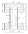
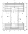
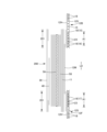
図1~図6は、パンツタイプ使い捨ておむつ100を示している。本パンツタイプ使い捨ておむつ100は、前身頃Fを構成する前側外装体12F及び後身頃Bを構成する後側外装体12Bと、前側外装体12Fから股間部を経て後側外装体12Bまで延在し、前側が前側外装体12Fに、及び後側が後側外装体12Bに固定された内装体200とを備えており、前側外装体12Fの両側部と後側外装体12Bの両側部とが接合されてサイドシール部12Aが形成され、外装体12F,12Bの前後端部により形成される開口が装着者の胴を通すウエスト開口WOとなり、内装体200の幅方向WDの両側において外装体12F,12Bの下縁及び内装体200の側縁によりそれぞれ囲まれる部分が脚を通す脚開口部LOとなっているものである。内装体200は、尿等の排泄物等を吸収保持する部分であり、外装体12は着用者の身体に対して内装体200を支えるための部分である。また、符号Yは展開状態におけるおむつの全長(前身頃Fのウエスト開口WOの縁から後身頃Bのウエスト開口WOの縁までの前後方向長さ)を示しており、符号Xは展開状態におけるおむつの全幅を示している。
1 to 6 show a pants-type
また、本パンツタイプ使い捨ておむつ100は、サイドシール部12Aを有する前後方向範囲(ウエスト開口WOから脚開口LOの上端に至る前後方向範囲)として定まる胴周り領域Tと、脚開口LOを形成する部分の前後方向範囲(前身頃Fのサイドシール部12Aを有する前後方向領域と後身頃Bのサイドシール部12Aを有する前後方向領域との間)として定まる中間領域Lとを有する。胴周り領域Tは、概念的にウエスト開口の縁部を形成する「ウエスト部」Wと、これよりも下側の部分である「ウエスト下方部」Uとに分けることができる。通常、胴周り領域T内に幅方向WDの伸縮応力が変化する境界(例えば弾性部材の太さや伸長率が変化する)を有する場合は、最もウエスト開口WO側の境界よりもウエスト開口WO側がウエスト部Wとなり、このような境界が無い場合は吸収体56又は内装体200よりもウエスト開口WO側がウエスト部Wとなる。これらの前後方向の長さは、製品のサイズによって異なり、適宜定めることができるが、一例を挙げると、ウエスト部Wは15~40mm、ウエスト下方部Uは65~120mmとすることができる。一方、中間領域Lの両側縁は被着者の脚周りに沿うようにコ字状又は曲線状に括れており、ここが装着者の脚を入れる部位となる。この結果、展開状態のパンツタイプ使い捨ておむつは、全体として略砂時計形状をなしている。
In addition, the pants-type
(内装体)
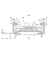
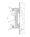
内装体200は任意の形状とすることができるが、図示の例では長方形である。内装体200は、図3~図5に示されるように、身体側となるトップシート30と、液不透過性シート11と、これらの間に介在された吸収要素50とを備えているものであり、吸収機能を担う本体部である。符号40は、トップシート30を透過した液を速やかに吸収要素50へ移行させるために、トップシート30と吸収要素50との間に設けられた中間シート(セカンドシート)を示しており、符号60は、内装体200の両脇に排泄物が漏れるのを防止するために、内装体200の両側に設けられた、身体側に起立する起き上がりギャザー60を示している。
(inner body)
The
内装体200の外装体12F,12Bに対する固定は、ヒートシール、超音波シールのような素材溶着による接合手段や、ホットメルト接着剤により行うことができる。図示例では、内装体200の裏面、つまりこの場合は液不透過性シート11の裏面及び起き上がりギャザー60の取付部分65に塗布されたホットメルト接着剤により外装体12の内面に対して固定されている。この内装体200と外装体12F,12Bとを固定する内外固定部201は、両者が重なる領域のほぼ全体に設けることができ、通常は内装体200の幅方向WDの両端部を除いた部分に設けることが好ましい。
Fixing of the
(トップシート)
トップシート30は、液を透過する性質を有するものであり、例えば、有孔又は無孔の不織布や、多孔性プラスチックシートなどを例示することができる。
(top sheet)
The
起き上がりギャザー60を設ける場合、トップシート30の両側部は、液不透過性シート11と起き上がりギャザー60との間を通して、吸収要素50の裏側まで回り込ませ、液不透過性シート11及び起き上がりギャザー60に対して接合することができる。
When the rising gathers 60 are provided, both sides of the
トップシート30は、裏側の部材に対する位置ずれを防止する等の目的で、ヒートシール、超音波シールのような素材溶着による接合手段や、ホットメルト接着剤により裏側に隣接する部材に固定することが望ましい。図示例では、トップシート30はその裏面に塗布されたホットメルト接着剤により中間シート40の表面及び包装シート58のうち吸収体56の表側に位置する部分の表面に固定されている。
The
(中間シート)
トップシート30を透過した液を速やかに吸収体へ移行させるために、トップシート30より液の透過速度が速い、中間シート40を設けることができる。この中間シート40は、液を速やかに吸収体へ移行させて吸収体による吸収性能を高めるばかりでなく、吸収した液の吸収体からの逆戻り現象を防止することができる。中間シート40は省略することもできる。
(intermediate sheet)
An
中間シート40としては、トップシート30と同様の素材や、スパンレース不織布、スパンボンド不織布、SMS不織布、パルプ不織布、パルプとレーヨンとの混合シート、ポイントボンド不織布又はクレープ紙を例示できる。特にエアスルー不織布が嵩高であるため好ましい。エアスルー不織布には芯鞘構造の複合繊維を用いるのが好ましく、この場合芯に用いる樹脂はポリプロピレン(PP)でも良いが剛性の高いポリエステル(PET)が好ましい。目付けは20~80g/m2が好ましく、25~60g/m2がより好ましい。不織布の繊維の太さは2.0~10dtexであるのが好ましい。不織布を嵩高にするために、繊維の全部又は一部の混合繊維として、芯が中央にない偏芯の繊維や中空の繊維、偏芯且つ中空の繊維を用いるのも好ましい。
Examples of the
図示の例の中間シート40は、吸収体56の幅より短く中央に配置されているが、全幅にわたって設けてもよい。中間シート40の長手方向長さは、吸収体56の長さと同一でもよいし、液を受け入れる領域を中心にした短い長さ範囲内であってもよい。
The
中間シート40は、裏側の部材に対する位置ずれを防止する等の目的で、ヒートシール、超音波シールのような素材溶着による接合手段や、ホットメルト接着剤により裏側に隣接する部材に固定することが望ましい。図示例では、中間シート40はその裏面に塗布されたホットメルト接着剤により包装シート58のうち吸収体56の表側に位置する部分の表面に固定されている。
The
(液不透過性シート)
液不透過性シート11の素材は、特に限定されるものではないが、例えば、ポリエチレンやポリプロピレン等のオレフィン系樹脂等からなるプラスチックフィルムや、不織布の表面にプラスチックフィルムを設けたラミネート不織布、プラスチックフィルムに不織布等を重ねて接合した積層シートなどを例示することができる。液不透過性シート11には、ムレ防止の観点から好まれて使用されている不透液性かつ透湿性を有する素材を用いることが好ましい。透湿性を有するプラスチックフィルムとしては、ポリエチレンやポリプロピレン等のオレフィン系樹脂中に無機充填剤を混練して、シートを成形した後、一軸又は二軸方向に延伸して得られた微多孔性プラスチックフィルムが広く用いられている。この他にも、マイクロデニール繊維を用い撥水剤を塗布した不織布等、プラスチックフィルムを用いずに液不透過性としたシートも、液不透過性シート11として用いることができる。
(liquid-impermeable sheet)
The material of the liquid-
液不透過性シート11は、図示のように吸収要素50の裏側に収まる幅とする他、防漏性を高めるために、吸収要素50の両側を回り込ませて吸収要素50のトップシート30側面の両側部まで延在させることもできる。
The liquid-
(起き上がりギャザー)
起き上がりギャザー60は、内装体200の両側部に沿って前後方向全体にわたり延在する帯状部材であり、トップシート30上を伝わって横方向に移動する排泄物を遮断し、横漏れを防止するために設けられているものである。本例の起き上がりギャザー60は、内装体200の側部から起立するように設けられ、付け根側の部分は幅方向WDの中央側に向かって斜めに起立し、中間部より先端側の部分は幅方向WDの外側に向かって斜めに起立するものである。
(Getting up gathers)
The rising gathers 60 are belt-like members extending along both sides of the
より詳細には、起き上がりギャザー60は、内装体200の前後方向長さに等しい長さを有する帯状のギャザーシート62を幅方向WDに折り返して二つに折り重ねるとともに、折り返し部分及びその近傍のシート間に、細長状のギャザー弾性部材63を長手方向に沿って伸長状態で、幅方向WDに間隔をあけて複数本固定してなるものである。起き上がりギャザー60のうち先端部と反対側に位置する基端部(幅方向WDにおいてシート折り返し部分と反対側の端部)は内装体200の側縁部の裏面に固定された取付部分65とされ、この取付部分65以外の部分は取付部分65から突出する突出部分66(折り返し部分側の部分)とされている。また、突出部分66は、幅方向WDの中央側に向かう付け根側部分と、この付け根側部分の先端から幅方向WDの外側に折り返された先端側部分とからなる。これは面接触タイプの起き上がりギャザーであるが、幅方向WDの外側に折り返されない線接触タイプの起き上がりギャザー(図示略)も採用することができる。そして、突出部分66のうち前後方向両端部が倒伏状態でトップシート30の側部表面に対して固定された前後固定部67とされる一方で、これらの間に位置する前後方向中間部は非固定の自由部分68とされ、この自由部分68に前後方向に沿うギャザー弾性部材63が伸長状態で固定されている。
More specifically, the riser gathers 60 are formed by folding a belt-shaped gather
起き上がりギャザー60の自由部分68では、ギャザーシート62の内側層及び外側層の貼り合わせや、その間に挟まれるギャザー弾性部材63の固定に、種々の塗布方法によるホットメルト接着剤及びヒートシールや超音波シール等の素材溶着による固定手段の少なくとも一方を用いることができる。ギャザーシート62の内側層及び外側層の全面を貼り合わせると柔軟性を損ねるため、ギャザー弾性部材63の接着部以外の部分は接着しないか弱く接着するのが好ましい。図示例では、コームガンやシュアラップノズル等の塗布手段によりギャザー弾性部材63の外周面にのみホットメルト接着剤を塗布してギャザーシート62の内側層及び外側層間に挟むことにより、当該ギャザー弾性部材63の外周面に塗布したホットメルト接着剤のみで、ギャザーシート62の内側層及び外側層へのギャザー弾性部材63の固定と、ギャザーシート62の内側層及び外側層間の固定とを行う構造となっている。
At the
また、起き上がりギャザー60に組み込まれる防水フィルム64とギャザーシート62との固定や、前後固定部67の内装体200の側部表面への固定に、種々の塗布方法によるホットメルト接着剤、及びヒートシールや超音波シール等の素材63溶着による手段の少なくとも一方を用いることができる。図示例では、防水フィルム64の固定にホットメルト接着剤のスロット塗布を使用している。また、図示例の前後固定部67の固定には、ホットメルト接着剤と素材溶着による手段を組み合わせているが、いずれか一方の手段のみで、これらの固定を行うこともできる。
In addition, for fixing the
ギャザーシート62としてはスパンボンド不織布(SS、SSS等)やSMS不織布(SMS、SSMMS等)、メルトブロー不織布等の柔軟で均一性・隠蔽性に優れた不織布に、必要に応じてシリコーンなどにより撥水処理を施したものを好適に用いることができ、繊維目付けは10~30g/m2程度とするのが好ましい。ギャザー弾性部材としては糸ゴム等を用いることができる。スパンデックス糸ゴムを用いる場合は、太さは470~1240dtexが好ましく、620~940dtexがより好ましい。固定時の伸長率は、150~350%が好ましく、200~300%がより好ましい。また、図示のように、二つに折り重ねたギャザーシートの間に防水フィルム64を介在させることもできる。
As the gather
起き上がりギャザー60の自由部分に設けられるギャザー弾性部材の本数は2~6本が好ましく、3~5本がより好ましい。配置間隔60dは3~10mmが適当である。このように構成すると、ギャザー弾性部材を配置した範囲で肌に対して面で当たりやすくなる。先端側だけでなく付け根側にもギャザー弾性部材を配置しても良い。
The number of gathering elastic members provided in the free portion of the rising gathers 60 is preferably 2-6, more preferably 3-5. A
起き上がりギャザー60の取付部分65の固定対象は、内装体200におけるトップシート30、液不透過性シート11、吸収要素50等適宜の部材とすることができる。
The fixing target of the mounting
以上の構造を有する起き上がりギャザー60では、ギャザー弾性部材の収縮力が前後方向両端部を近づけるように作用するが、突出部分66のうち前後方向両端部が起立しないように固定されるのに対して、それらの間は非固定の自由部分とされているため、自由部分のみが図3に示すように身体側に当接するように起立する。特に、取付部分65が内装体200の裏面側に位置していると、股間部及びその近傍において起き上がりギャザー60が幅方向WDの外側に開くように起立するため、起き上がりギャザー60が脚周りに面で当接するようになり、フィット性が向上するようになる。
In the rising gathers 60 having the above structure, the contractile force of the gather elastic member acts to bring the both ends in the front-rear direction closer together. In particular, when the mounting
(吸収要素)
吸収要素50は、吸収体56と、この吸収体56の全体を包む包装シート58とを有する。包装シート58は省略することもできる。
(absorbing element)
The
(吸収体)
吸収体56は、繊維の集合体により形成することができる。この繊維集合体としては、綿状パルプや合成繊維等の短繊維を積繊したものの他、セルロースアセテート等の合成繊維のトウ(繊維束)を必要に応じて開繊して得られるフィラメント集合体も使用できる。繊維目付けとしては、綿状パルプや短繊維を積繊する場合は、例えば100~300g/m2程度とすることができ、フィラメント集合体の場合は、例えば30~120g/m2程度とすることができる。合成繊維の場合の繊度は、例えば、1~16dtex、好ましくは1~10dtex、さらに好ましくは1~5dtexである。フィラメント集合体の場合、フィラメントは、非捲縮繊維であってもよいが、捲縮繊維であるのが好ましい。捲縮繊維の捲縮度は、例えば、2.54cm当たり5~75個、好ましくは10~50個、さらに好ましくは15~50個程度とすることができる。また、均一に捲縮した捲縮繊維を用いることができる。吸収体56中には高吸収性ポリマー粒子を分散保持させるのが好ましい。
(Absorber)
吸収体56は長方形形状でも良いが、図1及び図2にも示すように、前端部、後端部及びこれらの間に位置し、前端部及び後端部と比べて幅が狭い括れ部とを有する砂時計形状を成していると、吸収体56自体と起き上がりギャザー60の、脚周りへのフィット性が向上するため好ましい。
The
また、吸収体56の寸法は排尿口位置の前後左右にわたる限り適宜定めることができるが、前後方向及び幅方向WDにおいて、内装体の周縁部又はその近傍まで延在しているのが好ましい。なお、符号56Xは吸収体56の幅を示している。
The size of the
(高吸収性ポリマー粒子)
吸収体56には、その一部又は全部に高吸収性ポリマー粒子を含有させることができる。高吸収性ポリマー粒子とは、「粒子」以外に「粉体」も含む。高吸収性ポリマー粒子としては、この種の使い捨ておむつに使用されるものをそのまま使用でき、例えば500μmの標準ふるい(JIS Z8801-1:2006)を用いたふるい分け(5分間の振とう)でふるい上に残る粒子の割合が30重量%以下のものが望ましく、また、180μmの標準ふるい(JIS Z8801-1:2006)を用いたふるい分け(5分間の振とう)でふるい上に残る粒子の割合が60重量%以上のものが望ましい。
(superabsorbent polymer particles)
高吸収性ポリマー粒子の材料としては、特に限定無く用いることができるが、吸水量が40g/g以上のものが好適である。高吸収性ポリマー粒子としては、でんぷん系、セルロース系や合成ポリマー系などのものがあり、でんぷん-アクリル酸(塩)グラフト共重合体、でんぷん-アクリロニトリル共重合体のケン化物、ナトリウムカルボキシメチルセルロースの架橋物やアクリル酸(塩)重合体などのものを用いることができる。高吸収性ポリマー粒子の形状としては、通常用いられる粉粒体状のものが好適であるが、他の形状のものも用いることができる。 Materials for the superabsorbent polymer particles may be used without any particular limitation, but those having a water absorption of 40 g/g or more are suitable. Examples of superabsorbent polymer particles include starch-based, cellulose-based, and synthetic polymer-based particles, and starch-acrylic acid (salt) graft copolymers, starch-acrylonitrile copolymer saponified products, crosslinked products of sodium carboxymethyl cellulose, acrylic acid (salt) polymers, and the like can be used. As for the shape of the superabsorbent polymer particles, the powder particles that are commonly used are suitable, but other shapes can also be used.
高吸収性ポリマー粒子としては、吸水速度が70秒以下、特に40秒以下のものが好適に用いられる。吸水速度が遅すぎると、吸収体56内に供給された液が吸収体56外に戻り出てしまう所謂逆戻りを発生し易くなる。
As the superabsorbent polymer particles, those having a water absorption rate of 70 seconds or less, particularly 40 seconds or less are preferably used. If the water absorption rate is too slow, the liquid supplied into the
また、高吸収性ポリマー粒子としては、ゲル強度が1000Pa以上のものが好適に用いられる。これにより、嵩高な吸収体56とした場合であっても、液吸収後のべとつき感を効果的に抑制できる。
As the superabsorbent polymer particles, those having a gel strength of 1000 Pa or more are preferably used. As a result, even when the
高吸収性ポリマー粒子の目付け量は、当該吸収体56の用途で要求される吸収量に応じて適宜定めることができる。したがって一概には言えないが、50~350g/m2とすることができる。ポリマーの目付け量が50g/m2未満では、吸収量を確保し難くなる。350g/m2を超えると、効果が飽和する。
The basis weight of the superabsorbent polymer particles can be appropriately determined according to the absorption amount required for the use of the
必要であれば、高吸収性ポリマー粒子は、吸収体56の平面方向で散布密度あるいは散布量を調整できる。例えば、液の排泄部位を他の部位より散布量を多くすることができる。男女差を考慮する場合、男用は前側の散布密度(量)を高め、女用は中央部の散布密度(量)を高めることができる。また、吸収体56の平面方向において局所的(例えばスポット状)にポリマーが存在しない部分を設けることもできる。
If necessary, the superabsorbent polymer particles can be adjusted in the planar direction of the
(包装シート)
包装シート58を用いる場合、その素材としては、ティッシュペーパ、特にクレープ紙、不織布、ポリラミ不織布、小孔が開いたシート等を用いることができる。ただし、高吸収性ポリマー粒子が抜け出ないシートであるのが望ましい。クレープ紙に換えて不織布を使用する場合、親水性のSMS不織布(SMS、SSMMS等)が特に好適であり、その材質はポリプロピレン、ポリエチレン/ポリプロピレン複合材などを使用できる。目付けは、5~40g/m2、特に10~30g/m2のものが望ましい。
(packaging sheet)
When the
包装シート58の包装構造は適宜定めることができるが、製造容易性や前後端縁からの高吸収性ポリマー粒子の漏れ防止等の観点から、吸収体56の表裏面及び両側面を取り囲むように筒状に巻付け、かつその前後縁部を吸収体56の前後からはみ出させ、巻き重なる部分及び前後はみ出し部分の重なり部分をホットメルト接着剤、素材溶着等の接合手段により接合する構造が好ましい。
The packaging structure of the
(外装体)
外装体12F,12Bは、前身頃Fを構成する部分である前側外装体12Fと、後身頃Bを構成する部分である後側外装体12Bとからなり、前側外装体12F及び後側外装体12Bは股間側で連続しておらず、前後方向に離間されている。この離間距離12dは150~250mm程度とすることができる。この離間部分における内装体200の裏面の露出部分の一部(例えば前側外装体12Fと後側外装体12Bとの間に露出する部分の前後方向全体にわたるが、内装体200の前後端まで延びず、また両側縁も内装体200の両側縁までは達しない程度)又は全体を覆うように、不織布等からなる内装カバーシート12Mを貼り付けることが望ましいが、省略することもできる。また、図8に示すように、外装体12が、前身頃Fから後身頃Bにかけて股間を通り連続する一体的なものとすることもできる。
(Exterior body)
The
外装体12F,12Bは、胴周り領域Tと対応する前後方向範囲である胴周り部を有する。また、本例では、前側外装体12Fには中間領域Lと対応する部分を有していないが、後側外装体12Bは胴周り領域Tから中間領域L側に延び出る臀部カバー部14を有している。図示しないが、前側外装体12Fにも胴周り領域Tから中間領域L側に延び出る鼠蹊カバー部を設けたり、鼠径カバー部は設けるものの臀部カバー部は設けない構造としたり、前側外装体12F及び後側外装体12Bの両方に中間領域Lと対応する部分を設けなくても良い。また、図示例では、臀部カバー部14の下縁は、前側外装体12Fの下縁と同様、幅方向WDに沿う直線状に形成しているが、幅方向のWD外側に向かうにつれてウエスト開口WO側に位置するようになる曲線とすることもできる。
The
外装体12F,12Bは、図3~図5に示されるように、外側シート層12S及び内側シート層12Hをホットメルト接着剤や溶着等の接合手段により接合して形成されるものである。外側シート層12Sを形成するシート材及び内側シート層12Hを形成するシート材は、図5に示す例のように個別のシート材とする他、図7に示す例のように共通の一枚のシート材とすることもできる。すなわち、後者の場合、ウエスト側の縁(股間側の縁でも良い)で折り返された一枚のシート材の内側の部分及び外側の部分により内側シート層12H及び外側シート層12Sがそれぞれ形成される。なお、前者の例では、シート材の折り返し工程が少ないため、内側シート層12H及び外側シート層12Sを貼り合わせる際にずれにくいという利点があり、後者の例ではシート材の資材数が少ないという利点がある。
As shown in FIGS. 3 to 5, the
外側シート層12S及び内側シート層12Hを形成するシート材の端部や内装体200の前後端をウエスト開口WOに露出させると、シート材の角が肌に当たり肌触りが悪化するおそれや、後述するウエスト部W弾性部材やこれを固定するためのホットメルト接着剤が露出するおそれがある。よって、図5に示す例のように、外側シート層12Sを形成するシート材を、内側シート層12Hを形成するシート材のウエスト側の縁を回り込んでその内側に折り返して内面層を形成し、この内面層12rを内装体200のウエスト側の端部上まで延在させるのは好ましい。
If the ends of the sheet material forming the
外側シート層12S及び内側シート層12Hに用いるシート材としては特に限定されないが、例えば、熱可塑性樹脂からなる各種不織布を好適に使用することができる。不織布を用いる場合、その目付けは10~30g/m2程度とするのが好ましい。
The sheet material used for the
(伸縮領域)
図示例の外装体12F,12Bには、装着者の胴周りに対するフィット性を高めるために、外側シート層12S及び内側シート層12H間に糸ゴム等の細長状の弾性部材15~18が所定の伸長率で取り付けられ、弾性部材15~18とともに胴周り方向に弾性伸縮する伸縮領域A1が形成されている。弾性部材15~18としては、合成ゴムを用いても、天然ゴムを用いても良い。
(stretch area)
In the illustrated example of the
伸縮領域A2では、少なくとも弾性部材15~18の位置に配置されたホットメルト接着剤H1により、内側シート層12H及び外側シート層12Sが接合されるとともに、内側シート層12H及び外側シート層12Sに弾性部材15~18が固定されている。したがって、図2に示すように、伸縮領域A2における内側シート層12H及び外側シート層12Sに対する弾性部材15~18の固定は、弾性部材15~18の位置に配置されたホットメルト接着剤H1のみによりなされていてもよい。この構造は、内側シート層12H及び外側シート層12Sにはホットメルト接着剤H1を塗布せず、コームガンやシュアラップノズル等の塗布手段により弾性部材15~18の外周面にホットメルト接着剤H1を塗布して両シート層12S,12H間に挟むことにより製造することができる。図8に示すように、伸縮領域A2の幅方向WDの両端部では補強用のホットメルト接着剤H2が付加されていてもよい。図8に示す例は、スロットコートや、パターンコート(凸版方式でのホットメルト接着剤の転写)により、内側シート層12H及び外側シート層12Sのいずれか一方における、伸縮領域の両端部となる部位に補強用のホットメルト接着剤H2を塗布するとともに、コームガンやシュアラップノズル等の塗布手段により弾性部材15~18の外周面にのみホットメルト接着剤H1を塗布して両シート層12S,12H間に挟むことにより製造することができる。
In the elastic region A2, the
弾性部材15~18の配置は伸縮領域A1が設けられる限り特に限定されないが、図示例についてより詳細に説明すると以下のとおりである。すなわち、外装体12F,12Bのウエスト部Wにおける外側シート層12S及び内側シート層12H間には、幅方向WDの全体にわたり連続するように、複数のウエスト部弾性部材18が前後方向に間隔を空けて、かつ所定の伸長率で幅方向WDに沿って伸長された状態で取り付けられている。また、ウエスト部弾性部材18のうち、ウエスト下方部Uに隣接する領域に配設される1本又は複数本については、内装体200と重なっていてもよいし、内装体200と重なる幅方向WDの中央部を除いてその両側にそれぞれ設けてもよい。このウエスト部弾性部材18としては、太さ155~1880dtex、特に470~1240dtex程度(スパンデックス等の合成ゴムの場合。天然ゴムの場合には断面積0.05~1.5mm2、特に0.1~1.0mm2程度)の糸ゴムを、4~12mmの間隔で3~22本程度、それぞれ伸長率150~400%、特に220~320%程度で取り付けるのが好ましい。また、ウエスト部弾性部材18は、そのすべてを同じ太さと伸長率にする必要はなく、例えばウエスト部Wの上部と下部で太さと伸長率が異なるようにしてもよい。
The arrangement of the
また、外装体12F,12Bのウエスト下方部Uにおける外側シート層12S及び内側シート層12H間には、弾性部材からなるウエスト下方部弾性部材15,17が複数本、前後方向に間隔を空けて、かつ所定の伸長率で幅方向WDに沿って伸長された状態で取り付けられている。
In addition, a plurality of lower waist
ウエスト下方部弾性部材15,17としては、太さ155~1880dtex、特に470~1240dtex程度(合成ゴムの場合。天然ゴムの場合には断面積0.05~1.5mm2、特に0.1~1.0mm2程度)の糸ゴムを、1~15mm、特に3~8mmの間隔で5~30本程度、それぞれ伸長率200~350%、特に240~300%程度で取り付けるのが好ましい。
As the waist lower
また、後側外装体12Bの臀部カバー部14における外側シート層12S及び内側シート層12H間には、弾性部材からなるカバー部弾性部材16が複数本、前後方向に間隔を空けて、かつ所定の伸長率で幅方向WDに沿って伸長された状態で取り付けられている。
In addition, a plurality of cover section
カバー部弾性部材16としては、太さ155~1880dtex、特に470~1240dtex程度(合成ゴムの場合。天然ゴムの場合には断面積0.05~1.5mm2、特に0.1~1.0mm2程度)の糸ゴムを、5~40mm、特に5~20mmの間隔で2~10本程度、それぞれ伸長率150~300%、特に180~260%で取り付けるのが好ましい。
As the
前側外装体12Fに鼠径カバー部を設ける場合には同様にカバー部弾性部材を設けることができる。
When a groin cover portion is provided on the front side
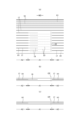
(非伸縮領域)
図示例のウエスト下方部Uや臀部カバー部14のように、吸収体56を有する前後方向範囲に弾性部材15~17を設ける場合には、その一部又は全部において吸収体56の幅方向WDの収縮を防止するために、吸収体56を有する前後方向範囲において吸収体56と幅方向WDに重なる部分の一部又は全部を含む幅方向WDの中間(好ましくは内外固定部201の全体を含む)が非伸縮領域A1とされ、その幅方向WDの両側が幅方向WDの全体にわたり伸縮領域A2とされていると好ましい。
(Non-stretch area)
When the
非伸縮領域A1は、伸縮領域A2から連続する内側シート層12H及び外側シート層12Sと、これら内側シート層12H及び外側シート層12S間に介在された、伸縮領域A2の弾性部材15~17から連続する独立収縮部分19とを有する領域である。独立収縮部分19は、弾性部材15~17における内側シート層12H及び外側シート層12Sを伴わずに収縮した部分である。非伸縮領域A1では、独立収縮部分19を形成するために、内側シート層12H及び外側シート層12Sの接合と、内側シート層12H及び外側シート層12Sに対する独立収縮部分19の固定とがなされていないことが好ましい。もちろん、独立収縮部分19の位置に配置されたホットメルト接着剤のみにより、内側シート層12H及び外側シート層12Sが伸縮領域A2よりも弱く接合されるとともに、内側シート層12H及び外側シート層12Sに独立収縮部分19が伸縮領域A2の弾性部材15~17よりも弱く固定されていてもよい。このため、独立収縮部分19に位置するホットメルト接着剤の塗布量を、伸縮領域A2におけるホットメルト接着剤の塗布量をよりも少なくすることができる。
The non-stretchable region A1 is a region having an
非伸縮領域A1は、幅方向WD及び前後方向LDの両方における中央部を含む少なくとも一か所に、内側シート層12H及び外側シート層12Sが直接に溶着された補強接合部23を有していると好ましい。この補強接合部23により、非伸縮領域A1における内側シート層12H及び外側シート層12Sの接合が補強され、外側シート層12Sが内側シート層12Hから浮き上がるといった事態や、外側シート層12Sに不規則かつ大きな皺が寄るといった事態が発生しにくくなり、見栄えが悪化するおそれが少ないものとなる。
The non-stretchable region A1 preferably has a reinforcing joint 23 where the
非伸縮領域A1における補強接合部23の形状及び配置は適宜定めることができる。補強接合部23の形状は、例えば図9及び図11に示すように点線状としたり、図12に示すように連続線状としたり、図10に示すように千鳥状等の点配列状(点状の補強接合部23が規則的又は不規則なパターンで間隔を空けて配置された配列)としたりすることができる。補強接合部23の配置は前後方向LD及び幅方向WDの少なくとも一方には間欠的であると好ましい。また、補強接合部23の配置は、例えば、図9及び図10に示すように、非伸縮領域A1における前後方向LD及び幅方向WDの全体にわたりある程度均一に補強接合部23を設けることが好ましいが、幅方向WDの一か所(図12)にのみ前後方向LDの全体にわたり設けてもよいし、図示しないが、幅方向WD及び前後方向LDの両方における中央部のみに設けることもできる。
The shape and arrangement of the reinforcing
補強接合部23の配置が、点配列状や点線状の場合、個々の補強接合部23は、真円形、楕円形、三角形、長方形、ひし形等の多角形、星形、雲形等、任意の形状とすることができる。この場合、個々の補強接合部23の寸法は特に限定されないが、前後方向LDの最大寸法は0.5~4mm、特に1~3mmとするのが好ましく、幅方向WDの最大寸法は0.5~4mm、特に1~3mmとするのが好ましい。また、前後方向LDの間隔は2~5mm、特に3~5mmとするのが好ましく、幅方向WDの間隔は0.5~4mm、特に1~3mmとするのが好ましい。
When the reinforcing
例えば、図9に示すように、補強接合部23が、前後方向LDに隣接する独立収縮部分19の間の間隔部分に、幅方向WDに沿って点線状又は線状に設けられていると好ましい。この場合、間隔部分のそれぞれに補強接合部23が配置されていることが好ましく、さらに非伸縮領域A1における前後方向LDの両端部にも補強接合部23が配置されているとより好ましい。間隔部分の一部のみ(例えば前後方向LDの中央部のみや、前後方向LDにひとつおき)に補強接合部23が配置されていてもよい。これにより、弾性部材15~17の独立収縮部分19が前後方向LDに移動したとしても、その移動は補強接合部23によって規制されるため、前後方向LDに隣接する他の独立収縮部分19と交差することがない。よって、弾性部材15~17の独立収縮部分19の形状が不規則になることによる見栄えの悪化を防止することができる。
For example, as shown in FIG. 9, it is preferable that the reinforcing
図示しないが、補強接合部23は、模様、絵(キャラクター含む)、文字(使用方法や使用補助、サイズ等の機能表示、あるいは製造者や製品名、特徴的機能等の標章表示等の表示等)又はこれらの組合せからなる表示状に設けられていてもよい。これにより、非伸縮領域A1の意匠性を向上することができる。 Although not shown, the reinforcing joint 23 may be provided in the form of a pattern, a picture (including characters), letters (function indications such as usage, usage assistance, size, etc., or indications such as mark indications such as manufacturer, product name, characteristic functions, etc.), or a combination of these. Thereby, the designability of the non-stretchable region A1 can be improved.
独立収縮部分19は、図9、図10に示すように、幅方向WD一方側の伸縮領域A2の弾性部材15~17から連続するもののみでもよいし、図11及び図12に示すように、前後方向LDにおける各弾性部材15~17の位置で、幅方向WD両側の伸縮領域A2の弾性部材15~17からそれぞれ連続するものが存在していてもよい。図示しないが、幅方向WD一方側の伸縮領域A2の弾性部材15~17から連続するものと、幅方向WD他方側の伸縮領域A2の弾性部材15~17から連続するものとが、前後方向LDに互い違いに存在していてもよい。
9 and 10, the
図11及び図12に示すように、幅方向WD両側の独立収縮部分19の長さが等しいと、見栄えが幅方向WD中央に関して左右対称になり、美観に優れる点で好ましい。もちろん、図9及び図10に示す例のように、幅方向WD両側の独立収縮部分19の長さが異なっていてもよい。
As shown in FIGS. 11 and 12, when the lengths of the
本パンツタイプ使い捨ておむつの製造における外装体12の形成に際しては、図14に示すように、伸縮領域A2となる部分及び非伸縮領域A1となる部分を通るように、内側シート層12H及び外側シート層12S間に細長状の弾性部材15~18を長手方向に伸長した状態で連続的に配置する。この際、伸縮領域A2となる部分では、弾性部材15~18の周面に塗布したホットメルト接着剤H1を介して内側シート層12H及び外側シート層12Sを接合するとともに、内側シート層12H及び外側シート層12Sに弾性部材15~18を固定する。また、非伸縮領域A1となる部分では、内側シート層12H及び外側シート層12Sの接合と、内側シート層12H及び外側シート層12Sに対する独立収縮部分19の固定とを行わない。非伸縮領域A1となる部分において、弾性部材15~17の周面に塗布したホットメルト接着剤のみにより、内側シート層12H及び外側シート層12Sを伸縮領域A2となる部分よりも弱く接合するとともに、内側シート層12H及び外側シート層12Sに弾性部材15~17を伸縮領域A2となる部分よりも弱く固定してもよい。
When forming the
その後、非伸縮領域A1となる部分の幅方向WDの一か所で内側シート層12Hの内側及び外側シート層12Sの外側から挟んで加圧及び加熱することにより弾性部材15~17を切断する。この切断により、製品においては加圧及び加熱した部分には切断痕跡22(圧縮痕跡や溶融痕跡)が残る。また、非伸縮領域A1に残る弾性部材15~18は、内がシート層及び外側シート層に非固定と(又は弱く固定)されているため、収縮しつつ内側シート層12H及び外側シート層12Sに対して移動する結果、自然長又はそれに近い状態の独立収縮部分19が形成され、非伸縮領域A1に伸縮性が生まれないこととなる。
After that, the
図示しないが、このようにして形成された外装体12F,12Bの連続体に対して、別途製造される内装体を順次取り付け、その前後を重ねるように折り畳んだ後に、個々のおむつとなる部分の境界の両側にサイドシール部12Aを形成し、さらにその境界で切断することにより、パンツタイプ使い捨ておむつを製造することができる。
Although not shown, separately manufactured inner bodies are sequentially attached to the continuous body of the
図13は、外装体12F,12Bの形成における弾性部材15~17の切断工程を示しており、所定の切断パターンに形成された切断凸部72を有する加圧部71を外周面に備え、切断凸部72が所望の温度に加熱されるシールロール70と、これに対向配置された表面平滑なアンビルロール80とにより、内側シート層12H及び外側シート層12S間に表示シート25及び弾性部材15~18を取り付けた切断対象を、内側シート層12Hがシールロール側(反対側としても良い)となるように挟み、切断凸部72とアンビルロール80の外周面との間に挟まれる部位のみ弾性部材15~17を加圧及び加熱して切断するものである。弾性部材15~17を切断するための加熱温度(切断凸部の温度)は、弾性部材15~17を確実に切断できる限り適宜定めれば良いが、製造ラインが高速であっても弾性部材15~17を確実に切断し、かつ弾性部材15~17の切断部が周囲部材に付着しないようにし、併せて切断位置で外側シート層12S及び内側シート層12Hを溶着するためには、弾性部材15~17の融点よりは低温であるが十分に高温とすることが好ましい。例えば、外側シート層12S及び内側シート層12Hに使用される不織布の融点は160~175℃程度であり、弾性部材15~17の融点は200~230℃程度である場合、加熱温度は180~200℃とすることができる。
FIG. 13 shows a step of cutting the
切断位置(切断痕跡22の位置)は、非伸縮領域A1となる部分の幅方向WDの一か所であれば特に限定されず、図9及び図10に示すように非伸縮領域A1の幅方向WDいずれか一方の端部であってもよいし、図11及び図12に示す例のように非伸縮領域A1の幅方向WDの中央部であってもよいし、これら以外の位置であってもよい。切断位置によって、独立収縮部分19の長さ及び配置が決まることになる。
The cutting position (the position of the cutting trace 22) is not particularly limited as long as it is one point in the width direction WD of the non-stretchable region A1, and may be either one end in the width direction WD of the non-stretchable region A1 as shown in FIGS. The location of the cut will determine the length and placement of the
切断凸部72の幅(切断痕跡22の幅方向WDの寸法)は適宜定めることができるが、非伸縮領域A1の幅方向WDの寸法の0.5~8%程度、又は0.5~5mm程度とすることが好ましい。 The width of the cutting protrusion 72 (the dimension in the width direction WD of the cut trace 22) can be determined as appropriate, but it is preferably about 0.5 to 8% of the dimension in the width direction WD of the non-stretchable region A1, or about 0.5 to 5 mm.
切断パターン(切断痕跡22)は特に限定されず、図10に示すように前後方向LDに間欠的なパターンとすることもできるが、図9、図11及び図12に示すように最もウエスト側の弾性部材15~17の切断位置から最も股間側の弾性部材15~17の切断位置まで前後方向LDに連続する線状パターンであると好ましい。このような線状パターンとしては、図示例のような直線状とする他、図示しないが曲線状や波線状のパターンとすることもできる。 The cutting pattern (cutting trace 22) is not particularly limited, and may be an intermittent pattern in the front-rear direction LD as shown in FIG. Such a linear pattern may be a linear pattern as shown in the drawing, or may be a curved or wavy pattern (not shown).
補強接合部23は、非伸縮領域A1となる部分で、内側シート層12Hの内側及び外側シート層12Sの外側から挟んで加圧及び加熱し、内側シート層12H及び外側シート層12Sを溶着することにより形成できる。例えば、図13及び図14(a)~(c)に示す例のように、弾性部材15~17の切断凸部72を有するシールロール70に、補強接合部23を形成するための溶着凸部73を形成すると、単一のシールロール70で弾性部材15~17の切断及び補強接合部23の形成を行うことができ、製造設備が簡素になるため好ましい。もちろん、弾性部材15~17の切断のための適切な加熱温度と、補強接合部23の形成のための適切な加熱温度が異なる場合等、必要に応じて、図14(c)に示すように、弾性部材15~17の切断凸部72を有する第1のシールロール70と、補強接合部23を形成するための溶着凸部73を有する第2のシールロール75とをMD方向に並べて配置することもできる。なお、補強接合部23の形成は、図13及び図14(a)に示すように弾性部材15~17の切断の切断後に行っても、図14(b)(d)に示すように、弾性部材15~17の切断の前に行っても、図14(c)に示すように、弾性部材15~17の切断と同時に行ってもよい。
The reinforcing
弾性部材15~17の切断の前又は切断と同時に補強接合部23を形成する場合、弾性部材15~17を加圧及び加熱するおそれがある。よって、例えば図11に示す例のように、非伸縮領域A1となる部分の幅方向WDの中間部(切断痕跡22)で弾性部材15~17を切断した後に、幅方向WDの両側に位置する独立収縮部分19の間の位置に補強接合部23を形成する等、独立収縮部分19を有しない幅方向WDの範囲に補強接合部23を形成すると好ましい。
If the reinforcing
弾性部材15~17の切断と補強接合部23の形成とを同時に行う場合、非伸縮領域A1となる部分の幅方向WDの中央部のみで同時に行うと、図12に示す例のように、切断痕跡22及び補強接合部23が、非伸縮領域A1の幅方向WDの中央部にのみ設けられ、幅方向WD両側の独立収縮部分19の長さが等しくなる。よって、補強接合部23を含めた見栄えが幅方向WDの中央に関して左右対称になり、美観に優れる点で好ましい。
When the cutting of the
弾性部材15~17の切断の前に補強接合部23を形成する場合、図9に示すように、前後方向LDに隣接する独立収縮部分19の間に、幅方向WDに沿って点線状又は線状に補強接合部23を形成すると、切断後に独立収縮部分19が収縮する際、独立収縮部分19が不規則な形状となりにくいため好ましい。
When the reinforcing
(後処理テープ)
図2及び図8に示すように、後側外装体12Bの非伸縮領域A1の外面には後処理テープ90が設けられている。すなわち、この後処理テープ90は、図15及び図16に示すように、外装体12の外側シート層12Sの外面に粘着剤94等により固定された、前後方向LDに延びる帯状の付根部91と、この付根部91のウエスト側から延び出る帯状の本体部92,93と、本体部92,93に設けられた粘着剤94とを有するものである。おむつの廃棄時には、おむつをトップシート30が内側になるとともに前身頃Fが内側となるように丸め若しくは折り畳んだ後、後処理テープ90の本体部92,93を剥離した後、この本体部92,93を、図17に示すように、丸めた若しくは折り畳んだおむつ100の後身頃Bからウエスト開口WOを越えて反対側の外面まで巻付け、粘着剤94により外装体12の外面に固定する。これにより、図17に示すように、おむつを丸め若しくは折り畳んだ状態に固定することができる。
(post-treatment tape)
As shown in FIGS. 2 and 8, a
後処理テープ90の本体部92,93は、付根部91のウエスト開口WO側から股間側に延びる第1部分92と、第1部分92の先端でウエスト開口WO側に折り返された第2部分93とを有しており、第1部分92における付根部91との対向面、及び第2部分93における第1部分92との対向面に、粘着剤94がそれぞれ設けられており、第1部分92が粘着剤94により付根部91上に、及び第2部分93が粘着剤94により第1部分92上にそれぞれ粘着されることにより、第1部分92及び第2部分93が折り畳み状態に固定されていると好ましい。この場合における付根部91及び本体部92,93は、図示例のように、複数のシートS1~S4を連結して形成する他、図示しないが、単一のシートにより形成することもできる。付根部91を複数のシートを連結して形成する場合、シートの数は特に限定されず、図示例では4枚のシートで構成されているが、これらよりも少ない又は多いシートで構成したりすることができる。後処理を行うときには、本体部92,93の先端部を摘まんで外装体12から離間する方向又はウエスト開口WO側に引っ張ることにより、図16に示すように、第1部分92及び第2部分93を順に剥がして展開する。本体部92,93を、展開と同時又は展開後に、ウエスト開口WO側に倒すと、第2部分93の粘着剤が外装体12と対向することとなる。
The
図示例についてより詳細に説明すると、この後処理テープ90は、外装体12側の面に粘着剤94が塗布され、この粘着剤94により外装体12の外面に固定された第1シートS1と、この第1シートS1における外側に折り返された先端部に連結された第2シートS2と、第2シートS2における外側に折り返された先端部に固定された第3シートS3とにより、三つ折り(断面Z字状)構造が形成されるとともに、第2シートS2が第1シートS1側の面に塗布された粘着剤94により第1シートS1に剥離可能に接着され、第3シートS3が第2シートS2側の面に塗布された粘着剤94により第2シートS2に剥離可能に接着されているものである。各シートS1~S3の粘着剤94側と反対側の面には剥離剤等の剥離加工が施されることにより剥離可能となり、各シートS1~S3間の粘着剤94同士が接着される部分、外装体12に対する粘着部分は剥離しないように連結される。また、第3シートS3の先端部には白色等の不透明色に着色された着色テープS4が粘着剤94により連結されて、視認性の良い摘み部(図示例では単一のシートの先端部が他の部分と異なる不透明色に着色される)が形成されている。
More specifically, the
後処理テープ90の寸法は特に限定されるものではないが、摘みやすさや、おむつを丸めた状態に固定したときの安定性、装着感等への影響を考慮すると、本体部92,93及び付根部91の幅方向WDの寸法91Wは11~15mm程度、付根部91の前後方向LDの寸法91Lはおむつの全長Yの0.1~0.2倍程度、本体部92,93の展開状態における前後方向LDの寸法90Lは、付根部91の前後方向LDの寸法91Lの1.4~1.7倍程度であることが好ましい。
The dimensions of the
付根部91及び本体部92,93の素材としては、例えばポリエチレンやポリプロピレン等のオレフィン系樹脂、ポリ塩化ビニル、PET等の合成樹脂性のシートを好適に用いることができるが、特に限定されるものではない。
As the material for the
粘着剤94は特に限定されず、合成ゴム系粘着剤、天然ゴム系粘着剤、アクリル樹脂系粘着剤、シリコーン樹脂系粘着剤等を用いることができる。 The adhesive 94 is not particularly limited, and a synthetic rubber-based adhesive, a natural rubber-based adhesive, an acrylic resin-based adhesive, a silicone resin-based adhesive, or the like can be used.
付根部91及び本体部92,93を有するものであれば、他の公知の後処理テープ90を採用することもできる。また、後処理テープ90の取付け位置は、外装体12の外面である限り特に限定されず、適所に設けることができる。後処理テープ90は、図示例のように後身頃Bに設けることが一般的となっているが、前身頃Fに設けてもよく、後身頃Bと前身頃Fの両方に設けてもよい。
Other known
一般に、後処理テープ90の付根部は非伸縮領域A1に固定されるため、貼り付け後には、丸めたおむつが広がろうとする力が付根部や粘着部を剥がすように作用する。よって、非伸縮領域A1における外側シート層12S及び内側シート層12Hの接合が弱かったり、無かったりすると、丸めたおむつが広がろうとする力は外側シート層12Sのみに局所的に加わり、外側シート層12Sが伸びたり、破れたりするおそれもある。したがって、このような観点からも、前述の補強接合部23を設けることが好ましい。
In general, the root portion of the
<明細書中の用語の説明>
明細書中の以下の用語は、明細書中に特に記載が無い限り、以下の意味を有するものである。
<Description of terms in the specification>
The following terms in the specification have the following meanings unless otherwise specified in the specification.
・「前後方向」とは図中に符号LDで示す方向(縦方向)を意味し、「幅方向」とは図中にWDで示す方向(左右方向)を意味し、前後方向と幅方向とは直交するものである。 ・"Front and back direction" means the direction (vertical direction) indicated by symbol LD in the figure, and "width direction" means the direction (left and right direction) indicated by WD in the figure, and the front and back direction and the width direction are orthogonal.
・「MD方向」及び「CD方向」とは、製造設備における流れ方向(MD方向)及びこれと直交する横方向(CD方向)を意味し、製品の部分によっていずれか一方が前後方向となるものであり、他方が幅方向となるものである。不織布のMD方向は、不織布の繊維配向の方向である。繊維配向とは、不織布の繊維が沿う方向であり、例えば、TAPPI標準法T481の零距離引張強さによる繊維配向性試験法に準じた測定方法や、前後方向及び幅方向の引張強度比から繊維配向方向を決定する簡易的測定方法により判別することができる。 ・"MD direction" and "CD direction" mean the flow direction (MD direction) and the transverse direction (CD direction) perpendicular to this in the manufacturing equipment, and depending on the part of the product, one of them is the front-back direction, and the other is the width direction. The MD direction of a nonwoven fabric is the direction of fiber orientation of the nonwoven fabric. The fiber orientation is the direction along which the fibers of the nonwoven fabric are aligned. For example, it can be determined by a measurement method according to the fiber orientation test method based on the zero-distance tensile strength of the TAPPI standard method T481, or by a simple measurement method that determines the fiber orientation direction from the tensile strength ratio in the front-back direction and the width direction.
・「表側」とはパンツタイプ使い捨ておむつを着用した際に着用者の肌に近い方を意味し、「裏側」とはパンツタイプ使い捨ておむつを着用した際に着用者の肌から遠い方を意味する。 - The "front side" means the side closer to the wearer's skin when the pants-type disposable diaper is worn, and the "back side" means the side farther from the wearer's skin when the pants-type disposable diaper is worn.
・「表面」とは部材の、パンツタイプ使い捨ておむつを着用した際に着用者の肌に近い方の面を意味し、「裏面」とはパンツタイプ使い捨ておむつを着用した際に着用者の肌から遠い方の面を意味する。 ・"Front surface" means the side of the member that is closer to the wearer's skin when the pants-type disposable diaper is worn, and the "back side" means the side that is farther from the wearer's skin when the pants-type disposable diaper is worn.
・「伸長率」は、自然長を100%としたときの値を意味する。例えば、伸長率が200%とは、伸長倍率が2倍であることと同義である。 - "Elongation rate" means a value when the natural length is taken as 100%. For example, an elongation rate of 200% is synonymous with an elongation ratio of 2 times.
・「ゲル強度」は次のようにして測定されるものである。人工尿(尿素:2wt%、塩化ナトリウム:0.8wt%、塩化カルシウム二水和物:0.03wt%、硫酸マグネシウム七水和物:0.08wt%、及びイオン交換水:97.09wt%を混合したもの)49.0gに、高吸収性ポリマーを1.0g加え、スターラーで攪拌させる。生成したゲルを40℃×60%RHの恒温恒湿槽内に3時間放置したあと常温にもどし、カードメーター(I.techno Engineering社製:Curdmeter-MAX ME-500)でゲル強度を測定する。 - "Gel strength" is measured as follows. To 49.0 g of artificial urine (urea: 2 wt%, sodium chloride: 0.8 wt%, calcium chloride dihydrate: 0.03 wt%, magnesium sulfate heptahydrate: 0.08 wt%, and deionized water: 97.09 wt%), 1.0 g of superabsorbent polymer is added and stirred with a stirrer. The resulting gel is left in a thermo-hygrostat at 40° C. and 60% RH for 3 hours, then returned to room temperature, and the gel strength is measured with a card meter (Curdmeter-MAX ME-500, manufactured by I. techno Engineering).
・「目付け」は次のようにして測定されるものである。試料又は試験片を予備乾燥した後、標準状態(試験場所は、温度23±1℃、相対湿度50±2%)の試験室又は装置内に放置し、恒量になった状態にする。予備乾燥は、試料又は試験片を温度100℃の環境で恒量にすることをいう。なお、公定水分率が0.0%の繊維については、予備乾燥を行わなくてもよい。恒量になった状態の試験片から、試料採取用の型板(100mm×100mm)を使用し、100mm×100mmの寸法の試料を切り取る。試料の重量を測定し、100倍して1平米あたりの重さを算出し、目付けとする。
- "Matsuke" is measured as follows. After pre-drying the sample or test piece, it is left in a test room or apparatus under standard conditions (test location:
・「厚み」は、自動厚み測定器(KES-G5 ハンディ圧縮計測プログラム)を用い、荷重:0.098N/cm2、及び加圧面積:2cm2の条件下で自動測定する。有孔不織布の厚みは、孔及びその周囲の突出部以外の部分で測定する。 - "Thickness" is automatically measured using an automatic thickness gauge (KES-G5 handy compression measurement program) under the conditions of a load of 0.098 N/cm 2 and a pressurized area of 2 cm 2 . The thickness of the perforated nonwoven fabric is measured at portions other than the perforations and the protrusions around them.
・吸水量は、JIS K7223-1996「高吸水性樹脂の吸水量試験方法」によって測定する。 ・The amount of water absorption is measured according to JIS K7223-1996 "Testing method for water absorption of super absorbent polymer".
・吸水速度は、2gの高吸収性ポリマー及び50gの生理食塩水を使用して、JIS K7224‐1996「高吸水性樹脂の吸水速度試験法」を行ったときの「終点までの時間」とする。 ・The water absorption rate is defined as "time to end point" when JIS K7224-1996 "Testing method for water absorption rate of superabsorbent polymer" is performed using 2g of superabsorbent polymer and 50g of physiological saline.
・「展開状態」とは、収縮や弛み無く平坦に展開した状態を意味する。 - "Unfolded state" means a flat unfolded state without contraction or slack.
・各部の寸法は、特に記載が無い限り、自然長状態ではなく展開状態における寸法を意味する。 ・Unless otherwise specified, the dimensions of each part mean the dimensions in the unfolded state, not in the natural length state.
・試験や測定における環境条件についての記載が無い場合、その試験や測定は、標準状態(試験場所は、温度23±1℃、相対湿度50±2%)の試験室又は装置内で行うものとする。
・If there is no description about environmental conditions for testing and measurement, the test and measurement shall be performed in a test room or equipment under standard conditions (test location:
本発明は、上記例等のパンツタイプ使い捨ておむつに利用できるものである。 INDUSTRIAL APPLICABILITY The present invention can be used for pants-type disposable diapers such as the above examples.
A1…非伸縮領域、A2…伸縮領域、H1…ホットメルト接着剤、L…中間領域、LD…前後方向、LO…脚開口部、T…胴周り領域、U…ウエスト下方部、W…ウエスト部、WD…幅方向、WO…ウエスト開口、11…液不透過性シート、12…外装体、12A…サイドシール部、12B…後側外装体、12F…前側外装体、12H…内側シート層、12S…外側シート層、12r…内面層、14…臀部カバー部、15~17…弾性部材、18…ウエスト部弾性部材、19…独立収縮部分、22…切断痕跡、23…補強接合部、30…トップシート、40…中間シート、50…吸収要素、56…吸収体、58…包装シート、60…起き上がりギャザー、62…ギャザーシート、90…後処理テープ、200…内装体、201…内外固定部。
A1 Non-stretchable region A2 Stretchable region H1 Hot-melt adhesive L Intermediate region LD Front-back direction LO Leg opening T Waist region U Waist lower portion W Waist opening WD Waist opening 11 Liquid-
Claims (3)
前身頃から後身頃にわたるように前記外装体に取り付けられた、吸収体を含む内装体と、
前身頃における外装体の両側部と後身頃における外装体の両側部とがそれぞれ接合されたサイドシール部と、
ウエスト開口及び左右一対の脚開口とを備え、
前記外装体は、前記吸収体を有する前後方向範囲に、幅方向中間に設けられた非伸縮領域と、この非伸縮領域の幅方向両側に設けられた伸縮領域とを有しており、
前記伸縮領域は、内側シート層と、外側シート層と、これら内側シート層及び外側シート層間に、前後方向に間隔を空けて取り付けられた幅方向に沿う複数本の細長状の弾性部材とを有し、前記弾性部材とともに幅方向に弾性伸縮する領域であり、
前記伸縮領域では、少なくとも前記弾性部材の位置に配置されたホットメルト接着剤により、前記内側シート層及び前記外側シート層が接合されるとともに、前記内側シート層及び外側シート層に前記弾性部材が固定されており、
前記非伸縮領域は、前記伸縮領域から連続する内側シート層及び外側シート層と、これら内側シート層及び外側シート層間に残された、前記伸縮領域の弾性部材から連続する独立収縮部分とを有し、前記独立収縮部分が内側シート層及び外側シート層を伴わずに収縮した領域であり、
前記非伸縮領域では、前記内側シート層及び前記外側シート層の接合と、前記内側シート層及び外側シート層に対する前記独立収縮部分の固定とがなされていないか、又は前記独立収縮部分の位置に配置されたホットメルト接着剤のみにより、前記内側シート層及び前記外側シート層が前記伸縮領域よりも弱く接合されるとともに、前記内側シート層及び外側シート層に前記独立収縮部分が前記伸縮領域の弾性部材よりも弱く固定されており、
前記非伸縮領域は、前記独立収縮部分を有する第1の幅方向範囲と、前記非伸縮領域の前後方向全体にわたり前記独立収縮部分及びそれ以外の前記弾性部材を有しない第2の幅方向範囲とを有し、前記第2の幅方向範囲は前記非伸縮領域の幅方向の中央部を含み、前記非伸縮領域の幅方向の中央部のみに前後方向の全体にわたり、前記内側シート層及び前記外側シート層が直接に溶着された補強接合部を有している、
パンツタイプ使い捨ておむつの製造方法であって;
前記外装体を形成するに際し、前記伸縮領域となる部分及び前記非伸縮領域となる部分を通るように、前記内側シート層及び外側シート層間に前記弾性部材を伸長状態で配置し、
前記伸縮領域となる部分では、少なくとも前記弾性部材の周面に塗布したホットメルト接着剤により、前記内側シート層及び前記外側シート層を接合するとともに、前記内側シート層及び外側シート層に前記弾性部材を固定し、
前記非伸縮領域となる部分では、前記内側シート層及び前記外側シート層の接合と、前記内側シート層及び外側シート層に対する前記独立収縮部分の固定とを行わないか、又は前記弾性部材の周面に塗布したホットメルト接着剤のみにより、前記内側シート層及び前記外側シート層を前記伸縮領域となる部分よりも弱く接合するとともに、前記内側シート層及び外側シート層に前記弾性部材を前記伸縮領域となる部分よりも弱く固定し、
その後、前記非伸縮領域となる部分の幅方向の一か所で、前記内側シート層の内側及び前記外側シート層の外側から挟んで加圧及び加熱することにより、前記弾性部材を切断するとともに、
前記弾性部材の切断の後に、前記非伸縮領域となる部分のうち前記第2の幅方向範囲で、前記内側シート層の内側及び前記外側シート層の外側から挟んで加圧及び加熱することにより、前記内側シート層及び外側シート層を溶着して、前記第2の幅方向範囲のみに前後方向の全体にわたり前記補強接合部を形成する、
ことを特徴とするパンツタイプ使い捨ておむつの製造方法。 An integrated exterior covering from the front body to the back body, or an exterior body provided separately for the front body and the back body;
an inner body including an absorbent attached to the outer body so as to extend from the front body to the back body;
a side seal portion in which both side portions of the exterior body of the front body and both side portions of the exterior body of the back body are respectively joined;
Equipped with a waist opening and a pair of left and right leg openings,
The exterior body has a non-stretchable region provided in the middle in the width direction and stretchable regions provided on both sides in the width direction of the non-stretchable region in the front-back direction range including the absorbent body,
The elastic region has an inner sheet layer, an outer sheet layer, and a plurality of elongated elastic members along the width direction attached between the inner sheet layer and the outer sheet layer at intervals in the front-rear direction.
In the elastic region, the inner sheet layer and the outer sheet layer are joined by a hot melt adhesive placed at least at the position of the elastic member, and the elastic member is fixed to the inner sheet layer and the outer sheet layer,
The non-stretchable region has an inner sheet layer and an outer sheet layer that are continuous from the stretchable region, and an independently shrinkable portion that remains between the inner sheet layer and the outer sheet layer and that is continuous from the elastic member of the stretchable region.
In the non-stretchable region, either the inner sheet layer and the outer sheet layer are not bonded and the independently contractible portion is not fixed to the inner sheet layer and the outer sheet layer, or the inner sheet layer and the outer sheet layer are bonded weaker than the stretchable region, and the independently contractible portion is fixed to the inner sheet layer and the outer sheet layer weaker than the elastic member of the stretchable region only by a hot melt adhesive placed at the position of the independently shrinkable portion.
The non-stretchable region has a first widthwise range having the independently contractible portion, and a second widthwise range over the entire front-rear direction of the non-stretchable region without the independent shrinkable portion and other elastic members.
A method for manufacturing a pants-type disposable diaper;
When forming the exterior body, the elastic member is arranged in a stretched state between the inner sheet layer and the outer sheet layer so as to pass through the portion to be the stretchable region and the portion to be the non-stretchable region,
In the stretchable region, at least the inner sheet layer and the outer sheet layer are joined with a hot-melt adhesive applied to the peripheral surface of the elastic member, and the elastic member is fixed to the inner sheet layer and the outer sheet layer,
In the portion to be the non-stretchable region, either the inner sheet layer and the outer sheet layer are not joined and the independently contractible portion is fixed to the inner sheet layer and the outer sheet layer, or the inner sheet layer and the outer sheet layer are joined weaker than the portion to be the stretchable region only by a hot melt adhesive applied to the peripheral surface of the elastic member, and the elastic member is fixed to the inner sheet layer and the outer sheet layer weaker than the portion to be the stretchable region;
After that, at one point in the width direction of the portion to be the non-stretchable region, the elastic member is cut by sandwiching from the inner side of the inner sheet layer and the outer side of the outer sheet layer and applying pressure and heat,
After cutting the elastic member, in the second width direction range of the portion to be the non-stretchable region, the inner sheet layer and the outer sheet layer are sandwiched from the inside of the inner sheet layer and the outer side of the outer sheet layer and subjected to pressure and heat, thereby welding the inner sheet layer and the outer sheet layer to form the reinforcing joint over the entire front and back direction only in the second width direction range.
A method for manufacturing a pants-type disposable diaper, characterized by:
請求項1記載のパンツタイプ使い捨ておむつの製造方法。 After cutting the elastic member at a widthwise intermediate portion of the non-stretchable region so that the lengths of the independently contractible portions on both sides in the width direction are equal, the reinforcing joint is formed in a second widthwise range located between the independently contractible portions on both sides in the widthwise direction.
The method for manufacturing the underpants-type disposable diaper according to claim 1.
請求項1又は2記載のパンツタイプ使い捨ておむつの製造方法。
The reinforcing joint is provided in a display shape consisting of a pattern, picture, letter, or a combination thereof;
The method for manufacturing the underpants-type disposable diaper according to claim 1 or 2.
Priority Applications (1)
| Application Number | Priority Date | Filing Date | Title |
|---|---|---|---|
| JP2019056557A JP7315350B2 (en) | 2019-03-25 | 2019-03-25 | Manufacturing method of pants-type disposable diaper |
Applications Claiming Priority (1)
| Application Number | Priority Date | Filing Date | Title |
|---|---|---|---|
| JP2019056557A JP7315350B2 (en) | 2019-03-25 | 2019-03-25 | Manufacturing method of pants-type disposable diaper |
Publications (3)
| Publication Number | Publication Date |
|---|---|
| JP2020156590A JP2020156590A (en) | 2020-10-01 |
| JP2020156590A5 JP2020156590A5 (en) | 2022-02-18 |
| JP7315350B2 true JP7315350B2 (en) | 2023-07-26 |
Family
ID=72640441
Family Applications (1)
| Application Number | Title | Priority Date | Filing Date |
|---|---|---|---|
| JP2019056557A Active JP7315350B2 (en) | 2019-03-25 | 2019-03-25 | Manufacturing method of pants-type disposable diaper |
Country Status (1)
| Country | Link |
|---|---|
| JP (1) | JP7315350B2 (en) |
Families Citing this family (1)
| Publication number | Priority date | Publication date | Assignee | Title |
|---|---|---|---|---|
| JP7165182B2 (en) * | 2020-12-23 | 2022-11-02 | 大王製紙株式会社 | Pants type disposable wearing article |
Citations (3)
| Publication number | Priority date | Publication date | Assignee | Title |
|---|---|---|---|---|
| JP2015512296A (en) | 2012-03-30 | 2015-04-27 | ザ プロクター アンド ギャンブルカンパニー | Apparatus and method for making absorbent articles |
| JP5779738B1 (en) | 2014-11-06 | 2015-09-16 | ユニ・チャーム株式会社 | Manufacturing method and manufacturing apparatus for sheet-like member according to absorbent article |
| JP2017064130A (en) | 2015-09-30 | 2017-04-06 | 大王製紙株式会社 | Underpants type disposable diaper |
-
2019
- 2019-03-25 JP JP2019056557A patent/JP7315350B2/en active Active
Patent Citations (3)
| Publication number | Priority date | Publication date | Assignee | Title |
|---|---|---|---|---|
| JP2015512296A (en) | 2012-03-30 | 2015-04-27 | ザ プロクター アンド ギャンブルカンパニー | Apparatus and method for making absorbent articles |
| JP5779738B1 (en) | 2014-11-06 | 2015-09-16 | ユニ・チャーム株式会社 | Manufacturing method and manufacturing apparatus for sheet-like member according to absorbent article |
| JP2017064130A (en) | 2015-09-30 | 2017-04-06 | 大王製紙株式会社 | Underpants type disposable diaper |
Also Published As
| Publication number | Publication date |
|---|---|
| JP2020156590A (en) | 2020-10-01 |
Similar Documents
| Publication | Publication Date | Title |
|---|---|---|
| JP6057355B2 (en) | Pants-type disposable diaper and method for manufacturing the same | |
| CN107970089B (en) | Pants-type disposable diaper | |
| JP6362250B2 (en) | Absorbent articles | |
| JP5992568B1 (en) | Pants-type disposable diaper | |
| WO2019188562A1 (en) | Stretchable structure for disposable wearable article and underpants-type disposable wearable article having stretchable structure | |
| JP2022117131A (en) | Underpants type disposable wearing article and manufacturing method thereof | |
| JP6495506B1 (en) | Stretch structure of disposable wearing article, and pants-type disposable wearing article having this stretchable structure | |
| CN113518604B (en) | Pants-type disposable wearing article | |
| JP6128460B2 (en) | Pants-type disposable diaper | |
| JP7315350B2 (en) | Manufacturing method of pants-type disposable diaper | |
| CN107970090B (en) | Pants-type disposable diaper | |
| WO2021059956A1 (en) | Pull-up disposable diaper | |
| JP2020018482A5 (en) | ||
| WO2017130783A1 (en) | Underpants-style disposable diaper and manufacturing method therefor | |
| JP7201358B2 (en) | Pants type disposable wearing article | |
| JP7129262B2 (en) | Elastic structure for disposable wearing article, and pants-type disposable wearing article having this elastic structure | |
| JP7158836B2 (en) | Pants type disposable diaper | |
| JP2021049284A5 (en) | ||
| JP7201739B2 (en) | Pants type disposable wearing article | |
| JP6183975B2 (en) | Pants-type disposable diaper and method for manufacturing the same | |
| JP7165182B2 (en) | Pants type disposable wearing article | |
| WO2023095464A1 (en) | Underpants-type disposable wearable article | |
| JP7315360B2 (en) | Pants type disposable wearing article | |
| JP7290918B2 (en) | disposable absorbent article | |
| JP7253912B2 (en) | absorbent article |
Legal Events
| Date | Code | Title | Description |
|---|---|---|---|
| A521 | Request for written amendment filed |
Free format text: JAPANESE INTERMEDIATE CODE: A523 Effective date: 20220209 |
|
| A621 | Written request for application examination |
Free format text: JAPANESE INTERMEDIATE CODE: A621 Effective date: 20220209 |
|
| A977 | Report on retrieval |
Free format text: JAPANESE INTERMEDIATE CODE: A971007 Effective date: 20221223 |
|
| A131 | Notification of reasons for refusal |
Free format text: JAPANESE INTERMEDIATE CODE: A131 Effective date: 20230203 |
|
| A521 | Request for written amendment filed |
Free format text: JAPANESE INTERMEDIATE CODE: A523 Effective date: 20230315 |
|
| A131 | Notification of reasons for refusal |
Free format text: JAPANESE INTERMEDIATE CODE: A131 Effective date: 20230512 |
|
| A521 | Request for written amendment filed |
Free format text: JAPANESE INTERMEDIATE CODE: A523 Effective date: 20230627 |
|
| TRDD | Decision of grant or rejection written | ||
| A01 | Written decision to grant a patent or to grant a registration (utility model) |
Free format text: JAPANESE INTERMEDIATE CODE: A01 Effective date: 20230707 |
|
| A61 | First payment of annual fees (during grant procedure) |
Free format text: JAPANESE INTERMEDIATE CODE: A61 Effective date: 20230713 |
|
| R150 | Certificate of patent or registration of utility model |
Ref document number: 7315350 Country of ref document: JP Free format text: JAPANESE INTERMEDIATE CODE: R150 |