WO2021059956A1 - Pull-up disposable diaper - Google Patents
Pull-up disposable diaper Download PDFInfo
- Publication number
- WO2021059956A1 WO2021059956A1 PCT/JP2020/033901 JP2020033901W WO2021059956A1 WO 2021059956 A1 WO2021059956 A1 WO 2021059956A1 JP 2020033901 W JP2020033901 W JP 2020033901W WO 2021059956 A1 WO2021059956 A1 WO 2021059956A1
- Authority
- WO
- WIPO (PCT)
- Prior art keywords
- exterior body
- width direction
- region
- waist
- sheet
- Prior art date
Links
Images


Classifications
-
- A—HUMAN NECESSITIES
- A61—MEDICAL OR VETERINARY SCIENCE; HYGIENE
- A61F—FILTERS IMPLANTABLE INTO BLOOD VESSELS; PROSTHESES; DEVICES PROVIDING PATENCY TO, OR PREVENTING COLLAPSING OF, TUBULAR STRUCTURES OF THE BODY, e.g. STENTS; ORTHOPAEDIC, NURSING OR CONTRACEPTIVE DEVICES; FOMENTATION; TREATMENT OR PROTECTION OF EYES OR EARS; BANDAGES, DRESSINGS OR ABSORBENT PADS; FIRST-AID KITS
- A61F13/00—Bandages or dressings; Absorbent pads
- A61F13/15—Absorbent pads, e.g. sanitary towels, swabs or tampons for external or internal application to the body; Supporting or fastening means therefor; Tampon applicators
- A61F13/45—Absorbent pads, e.g. sanitary towels, swabs or tampons for external or internal application to the body; Supporting or fastening means therefor; Tampon applicators characterised by the shape
- A61F13/49—Absorbent articles specially adapted to be worn around the waist, e.g. diapers
- A61F13/496—Absorbent articles specially adapted to be worn around the waist, e.g. diapers in the form of pants or briefs
-
- A—HUMAN NECESSITIES
- A61—MEDICAL OR VETERINARY SCIENCE; HYGIENE
- A61F—FILTERS IMPLANTABLE INTO BLOOD VESSELS; PROSTHESES; DEVICES PROVIDING PATENCY TO, OR PREVENTING COLLAPSING OF, TUBULAR STRUCTURES OF THE BODY, e.g. STENTS; ORTHOPAEDIC, NURSING OR CONTRACEPTIVE DEVICES; FOMENTATION; TREATMENT OR PROTECTION OF EYES OR EARS; BANDAGES, DRESSINGS OR ABSORBENT PADS; FIRST-AID KITS
- A61F13/00—Bandages or dressings; Absorbent pads
- A61F13/15—Absorbent pads, e.g. sanitary towels, swabs or tampons for external or internal application to the body; Supporting or fastening means therefor; Tampon applicators
- A61F13/51—Absorbent pads, e.g. sanitary towels, swabs or tampons for external or internal application to the body; Supporting or fastening means therefor; Tampon applicators characterised by the outer layers
Definitions
- the present invention relates to a pants-type disposable diaper having a two-part exterior structure with improved buttock coverage.
- Pants-type disposable diapers with a two-piece exterior structure are such that the front exterior body that constitutes at least the waist circumference of the front body, the rear exterior body that constitutes at least the waist circumference of the back body, and the front exterior body to the rear exterior body. It is provided with an interior body including an absorber attached to the exterior body, and both sides of the front exterior body and both sides of the rear exterior body are joined to form a side seal, whereby the waist opening and the left and right sides are formed. A pair of leg openings are formed (see, for example, Patent Document 1).
- a waist area that is defined as a range in the front-rear direction corresponding to the side seal, or an intermediate area that is located between the front and rear waist areas and has a stretchable area that expands and contracts in the width direction has a relatively good fit to the body. It is expensive.
- the fit of the leg opening has to be reduced. That is, since the distance from the position corresponding to the inseam of the interior body to the intersection position between the interior body and the exterior body is long in the pants-type disposable diaper of the exterior two-piece type, the interior body swings left and right with the intersection position as a fulcrum. Because it is easy to handle, the interior body is easier to move in the lateral direction compared to the type that has an integrated outer body that is continuous from the front body to the back body.
- the pants-type disposable diaper of the exterior two-piece type has a shape in which the crotch-side edge of the exterior body is straight or close to the width direction, and intersects the side edge of the interior body at a right angle or an angle close to it. .. These mean that, among the edges of the leg openings, the fit tends to be insufficient in the vicinity of the intersection position between the side edge of the interior body and the crotch side edge of the exterior body.
- side flaps extending laterally from the rising gathers extend in the front-rear direction from the front exterior body to the rear exterior body, and the side flaps elastically expand and contract in the front-rear direction.
- the side expansion / contraction area elastically supports the lateral movement of the interior body, and the side expansion / contraction area covers the side of the interior body, so that a gap is generated on the side of the interior body. It is preferable because it becomes difficult.
- the inner / outer joint portion where the interior body and the exterior body are joined extends to the side flap.
- the inner / outer joint portion has an overlapping portion between the expansion / contraction region of the exterior body and the side expansion / contraction region of the interior body, the side flaps of the interior body contract in the width direction, and the cover width by the side flaps becomes narrow. It ends up.
- the width of the cover by the side flaps of the interior body is narrowed at the back body, there is a problem that the interior body easily bites into the intergluteal cleft because the buttocks cannot be covered over a wide area.
- the main subject of the present invention is to improve the covering property of the buttocks and the like.
- the pants-type disposable diapers that solve the above problems are as follows. ⁇ First aspect> The front exterior body that constitutes at least the waist circumference of the front body, and the rear exterior body that constitutes at least the waist circumference of the back body, An interior body including an absorber provided from the front exterior body to the rear exterior body, and An inner / outer joint portion to which the interior body, the front exterior body, and the rear exterior body are joined, respectively. A side seal in which both side portions of the front exterior body and both side portions of the rear exterior body are joined, respectively.
- the front exterior body and the rear exterior body elastically expand and contract in the width direction including the lower end portion defined as the most leg opening side portion when the front-rear direction range having the side seal is divided into four equal parts in the front-rear direction. It has a stretchable area around the waist and On both sides of the interior body, side flaps extending laterally from the absorber extend in the front-rear direction from the front exterior body to the rear exterior body.
- the side flap has a side elastic region that elastically expands and contracts in the front-rear direction at least in a portion between a portion that overlaps the front exterior body and a portion that overlaps the rear exterior body.
- the elastic region around the waist of the rear exterior body is provided at least in a portion overlapping the left and right side flaps.
- the left and right side flaps have a post-joining region joined with a portion including the lower end of the rear exterior body.
- the post-joining region is contracted in the width direction and is expandable in the width direction together with the elastic region around the waist of the rear exterior body.
- the tensile force when the lower end of the front exterior body is extended to the elastic limit in the width direction and then contracted to the dimension of 3/4 of the extension causes the lower end of the rear exterior body to reach the elastic limit in the width direction. It is larger than the tensile force when it is stretched and then shrunk to its 3/4 size. Pants-type disposable diapers that feature this.
- the rear joint region of the side flap contracts in the width direction together with the elastic region around the waist of the rear exterior body in the state of natural length (before wearing).
- the tensile force when the lower end of the front exterior body is extended to the elastic limit in the width direction and then contracted to the dimension of 3/4 of that is the lower end portion of the rear exterior body.
- the posterior junction region of the side flaps expands more in the width direction, the side flaps cover the buttocks more extensively, and the interior body is less likely to bite into the intergluteal cleft.
- the "tensile force when the diaper is stretched to the elastic limit in the width direction and then contracted to the dimension of 3/4" is the state when the wearer of the conforming size wears the general pants type disposable diaper. Is assumed.
- ⁇ Second aspect> The tensile force when the lower end of the front exterior body is extended to the elastic limit in the width direction and then contracted to the dimension of 3/4 of the extension causes the lower end of the rear exterior body to reach the elastic limit in the width direction. It is 1.3 to 3.0 times the tensile force when it is stretched and then shrunk to its 3/4 size.
- the difference in tensile force between the lower end portion of the front exterior body and the lower end portion of the rear exterior body may be appropriately determined, but is usually preferably within the range of this embodiment.
- Pants-type disposable diaper according to the first or second aspect.
- the width direction of the post-joining region can be appropriately determined, but it is preferably sufficiently wide, and usually, it is preferably within the range of this embodiment.
- the front exterior body and the rear exterior body are rectangular in which the dimensions in the front-rear direction and the dimensions in the width direction are the same.
- the dimensions of the front exterior body and the rear exterior body in the front-rear direction are 0.2 to 0.4 times the total length of the product.
- a pants-type disposable diaper according to any one of the first to third aspects.
- the front exterior body and the rear exterior body are rectangular in which the dimensions in the front-rear direction and the dimensions in the width direction are the same.
- the appropriate front-rear dimensions of the front and rear exteriors are 0.2 to 0.4 times the overall length of the product.
- the covering property of the buttocks is lowered only by the rear exterior body, but the covering property of the buttocks can be supplemented by the side flap of the interior body described above.
- the elastic region around the waist of the front exterior body is provided at least in a portion overlapping the left and right side flaps.
- the left and right side flaps have a front joining region joined to a portion including the lower end of the front exterior body.
- the front joint region is contracted in the width direction and is expandable in the width direction together with the elastic region around the waist of the front exterior body.
- the front joint area of the side flap contracts in the width direction together with the elastic area around the waist of the front exterior body in the state of natural length (before wearing).
- the tensile force when the lower end of the front exterior body is extended to the elastic limit in the width direction and then contracted to the dimension of 3/4 of that is the lower end portion of the rear exterior body.
- the side expansion / contraction region is a region in which one or a plurality of elongated side elastic members are provided on the side flap along the front-rear direction and at intervals from each other.
- the side flap has a hollow portion extending in the front-rear direction from the front joining region to the back joining region along its side edge. Due to the contraction of the side elastic member, the portion of the side flap including the hollow portion contracts in the front-rear direction to form side gathers.
- a pants-type disposable diaper according to any one of the first to fifth aspects.
- the elastic region around the waist of the rear exterior body extends in the width direction (extends longer) than the elastic region around the waist of the front exterior body, and the rear joining region of the side flaps extends in width. Since it expands more in the direction, the bulge of the hollow portion becomes closer to flat toward the post-joining region, and the fit to the buttocks becomes better. Further, in the case of the sixth aspect, the width of the side flap becomes narrower from the rear to the front, and the bulge of the hollow portion becomes larger from the back to the front, so that the fit to the inguinal region is particularly good.
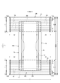
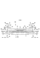
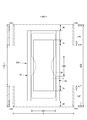
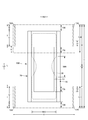
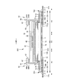
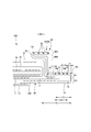
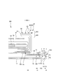
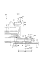
- FIG. 1 It is a top view which shows the inner surface of the pants type disposable diaper in the unfolded state. It is a top view which shows the outer surface of the pants type disposable diaper in the unfolded state. It is a 2-2 sectional view of FIG. It is a cross-sectional view of 3-3 of FIG. (A) is a 4-4 cross-sectional view of FIG. 1, and (b) is a 5-5 cross-sectional view of FIG. It is a perspective view of a pants type disposable diaper. It is a top view which shows the outer surface of the interior body in a developed state together with the outline of the exterior body. It is a top view which shows the outer surface of the interior body in the unfolded state together with the outline of the exterior body.
- FIG. 5 is a cross-sectional view of another example corresponding to the 3-3 cross section of FIG.
- FIG. 3 is an enlarged cross-sectional view of a main part of FIG.
- FIG. 9 is an enlarged cross-sectional view of a main part of FIG. It is sectional drawing which enlarges and shows the part which has a post-joining area. It is sectional drawing which shows the part which has a pre-joining area enlarged. It is a top view which shows the part which has a post-joining area in an enlarged manner. It is a top view which shows the part which has a pre-junction area in an enlarged manner. It is a top view which shows the mounting state schematicly. It is a front view which shows the method of a tensile test schematicly.
- the dotted pattern portion in the cross-sectional view shows an adhesive as a joining means for joining the constituent members located on the front side and the back side thereof, and is a solid, bead, curtain, summit or spiral coating of hot melt adhesive, or pattern coating.
- the hot melt adhesive include EVA type, adhesive rubber type (elastomer type), olefin type, polyester / polyamide type and the like, but they can be used without particular limitation.
- a joining means for joining each component a means by material welding such as a heat seal or an ultrasonic seal can also be used.
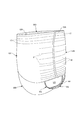
- FIGS. 1 to 6 show an example of a pants-type disposable diaper.
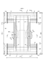
- This pants-type disposable diaper has a rectangular front exterior body 12F that constitutes at least the waist circumference of the front body F, a rectangular rear exterior body 12B that constitutes at least the waist circumference of the back body B, and a crotch from the front exterior body 12F. It is provided with an interior body 200 provided on the exterior bodies 12F and 12B so as to extend through the portion to the rear exterior body 12B. Both side portions of the front exterior body 12F and both side portions of the rear exterior body 12B are joined to form a side seal 12A, whereby an opening formed by the front and rear ends of the exterior bodies 12F and 12B is formed by the wearer.
- the waist opening WO through which the body passes, and the portions surrounded by the lower edges of the exterior bodies 12F and 12B and the side edges of the interior body 200 on both sides in the width direction of the interior body 200 are leg openings LO through which the legs pass.
- the interior body 200 is a part that absorbs and holds excrement such as urine, and the exterior bodies 12F and 12B are parts for supporting the interior body 200 with respect to the wearer's body.
- the reference numeral Y indicates the total length of the diaper in the unfolded state (the length in the front-rear direction from the edge of the waist opening WO of the front body F to the edge of the waist opening WO of the rear body B), and the reference numeral X indicates the diaper in the unfolded state. Shows the full width of.
- This pants type disposable diaper has a waist circumference region T defined as a front-rear direction range having a side seal 12A (a front-rear direction range from the waist opening WO to the upper end of the leg opening LO) and a front-back direction range of a portion forming the leg opening LO. It has an intermediate region L defined as (between the front-rear region having the side seal 12A of the front body F and the front-rear region having the side seal 12A of the back body B).
- the waist circumference region T can be divided into a "waist portion” W that conceptually forms an edge portion of the waist opening and a "waist lower portion" U that is a portion below the waist portion.
- the waist opening WO side is the waist rather than the boundary on the waist opening WO side. If there is no such boundary, the waist extending portion 12E extending toward the waist opening WO side from the absorber 56 or the interior body 200 becomes the waist portion W.
- These lengths in the front-rear direction vary depending on the size of the product and can be appropriately determined.
- the waist portion W can be 15 to 40 mm and the waist lower portion U can be 65 to 120 mm.
- both side edges of the intermediate region L are constricted in a U-shape or a curved shape along the circumference of the wearer's legs, and this is a portion for inserting the wearer's legs.
- the unfolded pants-type disposable diaper has an hourglass shape as a whole.
- the interior body 200 can take any shape, but in the illustrated example, it is substantially rectangular. As shown in FIGS. 3 to 5, the interior body 200 includes a top sheet 30 on the body side, a liquid-impermeable sheet 11, and an absorbing element 50 interposed between them. Yes, it has an absorption function. Reference numeral 40 indicates an intermediate sheet provided between the top sheet 30 and the absorption element 50 in order to quickly transfer the liquid that has passed through the top sheet 30 to the absorption element 50, and reference numeral 60 indicates an interior body. In order to prevent excrement from leaking to both sides of the 200, the rising gathers 60 extending from both sides of the interior body 200 so as to be in contact with the wearer's legs are shown.
- the size of the width direction WD of the interior body 200 can be appropriately determined, but for example, it can be 1 to 1.5 times the size of the width direction WD of the absorber 56.
- the top sheet 30 has a property of allowing liquid to permeate, and examples thereof include a perforated or non-perforated non-woven fabric and a porous plastic sheet. Further, the top sheet 30 may be made of one sheet or may be made of a laminated sheet obtained by laminating two or more sheets. Similarly, the top sheet 30 may be composed of one sheet or two or more sheets in the plane direction.
- Both sides of the top sheet 30 may be folded back on the side edge of the absorbing element 50, or may be projected laterally from the side edge of the absorbing element 50 without being folded back.
- the top sheet 30 may be fixed to a member adjacent to the back side by a joining means by material welding such as a heat seal or an ultrasonic seal, or by a hot melt adhesive for the purpose of preventing misalignment with respect to the member on the back side. desirable.
- the top sheet 30 is fixed to the surface of the intermediate sheet 40 and the surface of the packaging sheet 58 located on the front side of the absorber 56 by a hot melt adhesive applied to the back surface thereof.
- an intermediate sheet (also referred to as a "second sheet") 40 having a faster liquid permeation speed than the top sheet 30 can be provided.
- the intermediate sheet 40 is for quickly transferring the liquid to the absorber 56 to improve the absorption performance by the absorber 56 and to prevent the absorbed liquid from returning from the absorber 56.
- the intermediate sheet 40 may be omitted.
- the intermediate sheet 40 examples include the same materials as the top sheet 30, spunlace non-woven fabric, spunbonded non-woven fabric, SMS non-woven fabric, pulp non-woven fabric, mixed sheet of pulp and rayon, point-bonded non-woven fabric or crepe paper.
- the air-through non-woven fabric is preferable because it is bulky. It is preferable to use a composite fiber having a core-sheath structure for the air-through non-woven fabric.
- the resin used for the core may be polypropylene (PP), but polyester (PET) having high rigidity is preferable.
- Basis weight is preferably 17 ⁇ 80g / m 2, more preferably 25 ⁇ 60g / m 2.
- the thickness of the raw material fiber of the non-woven fabric is preferably 2.0 to 10 dtex.
- the intermediate sheet 40 in the illustrated example is arranged in the center shorter than the width of the absorber 56, it may be provided over the entire width.
- the length of the intermediate sheet 40 in the front-rear direction may be the same as the total length of the diaper, may be the same as the length of the absorbing element 50, or may be within a short length range centered on the region for receiving the liquid.
- the intermediate sheet 40 may be fixed to a member adjacent to the back side by a joining means by material welding such as a heat seal or an ultrasonic seal or a hot melt adhesive for the purpose of preventing misalignment with respect to the member on the back side. desirable.
- the intermediate sheet 40 is fixed to the surface of the portion of the packaging sheet 58 located on the front side of the absorber 56 by the hot melt adhesive applied to the back surface thereof.
- the material of the liquid-impermeable sheet 11 is not particularly limited, but for example, a plastic film made of an olefin resin such as polyethylene or polypropylene, a laminated non-woven fabric in which a plastic film is provided on the surface of the non-woven fabric, or a plastic film.
- a plastic film made of an olefin resin such as polyethylene or polypropylene
- a laminated non-woven fabric in which a plastic film is provided on the surface of the non-woven fabric or a plastic film.
- An example is a laminated sheet in which a non-woven fabric or the like is laminated and bonded to the surface.
- a microporous plastic film obtained by kneading an inorganic filler in an olefin resin such as polyethylene or polypropylene to form a sheet and then stretching it in a uniaxial or biaxial direction.
- an olefin resin such as polyethylene or polypropylene
- methods such as non-woven fabrics using microdenyl fibers, strengthening of leakage resistance by reducing the voids of the fibers by applying heat or pressure, and coating of highly water-absorbent resin or hydrophobic resin or water-repellent agent.
- liquid-impermeable sheet without using a plastic film can also be used as the liquid-impermeable sheet 11, but it has sufficient adhesive strength when bonded to the cover non-woven fabric 13 described later via a hot-melt adhesive. Therefore, it is desirable to use a resin film.
- the liquid-impermeable sheet 11 has a width that fits on the back side of the absorbing element 50, and in order to improve leakage resistance, both sides of the absorbing element 50 are wrapped around the side surface of the top sheet 30 of the absorbing element 50. It can also be extended to both sides.
- the width of the extending portion is appropriately about 5 to 20 mm on each of the left and right sides.
- the absorbing element 50 has an absorbing body 56 and a packaging sheet 58 that encloses the entire absorbing body 56.
- the packaging sheet 58 may be omitted.
- the absorber 56 can be formed by an aggregate of fibers.
- the fiber aggregate is obtained by stacking short fibers such as cotton-like pulp and synthetic fibers, and by opening the tow (fiber bundle) of synthetic fibers such as cellulose acetate as necessary. Can also be used.
- the fiber basis weight can be, for example, about 100 to 300 g / m 2 when stacking cotton-like pulp or short fibers, and about 30 to 120 g / m 2 for filament aggregates, for example. Can be done.
- the fineness is, for example, 1 to 16 dtex, preferably 1 to 10 dtex, and more preferably 1 to 5 dtex.
- the filament may be a non-crimped fiber, but is preferably a crimped fiber.
- the degree of crimping of the crimped fibers can be, for example, 5 to 75 fibers per 2.54 cm, preferably 10 to 50 fibers, and more preferably about 15 to 50 fibers.
- uniformly crimped crimped fibers can be used. It is preferable to disperse and hold the highly absorbent polymer particles in the absorber 56.
- the absorber 56 may have a rectangular shape, but as shown in FIG. 7 and the like, if the absorber 56 has an hourglass shape having a constricted portion 56N narrower than both front and rear sides in the middle in the front-rear direction, the absorber 56 itself This is preferable because the fit of the rising gather 60 around the legs is improved.
- the dimensions of the absorber 56 can be appropriately determined, it is preferable that the absorber 56 extends from a position overlapping the front exterior body to a position overlapping the rear exterior body through the crotch portion, and the LD and width in the front-rear direction as shown in the illustrated example. In the direction WD, it can extend to the peripheral portion of the interior body 200 or its vicinity.
- Reference numeral 56X indicates the entire width of the absorber 56.
- the absorber 56 may contain highly absorbent polymer particles in part or all of it.
- the highly absorbent polymer particles include "powder" in addition to "particles".
- those used for this kind of disposable diaper can be used as they are, for example, sieved by sieving (shaking for 5 minutes) using a standard sieve (JIS Z8801-1: 2006) of 500 ⁇ m. It is desirable that the proportion of particles remaining in the sieve is 30% by weight or less, and the particles falling under the sieve by this sieving are sieved using a standard sieve of 180 ⁇ m (JIS Z8801-1: 2006) (shaking for 5 minutes). It is desirable that the proportion of particles remaining on the sieve is 60% by weight or more.
- the material of the highly absorbent polymer particles can be used without particular limitation, but a material having a water absorption of 40 g / g or more is preferable.
- Highly absorbent polymer particles include starch-based, cellulosic-based and synthetic polymer-based ones, which are starch-acrylic acid (salt) graft copolymers, saponified starch-acrylonitrile copolymers, and crosslinked sodium carboxymethyl cellulose.
- a substance or an acrylic acid (salt) polymer or the like can be used.
- As the shape of the highly absorbent polymer particles a commonly used powder or granular material is preferable, but other shapes can also be used.
- the highly absorbent polymer particles those having a water absorption rate of 70 seconds or less, particularly 40 seconds or less, are preferably used. If the water absorption rate is too slow, so-called reversion, in which the liquid supplied into the absorber 56 returns to the outside of the absorber 56, is likely to occur.
- the highly absorbent polymer particles those having a gel strength of 1000 Pa or more are preferably used. As a result, even when the bulky absorber 56 is used, the sticky feeling after liquid absorption can be effectively suppressed.
- the basis weight of the highly absorbent polymer particles can be appropriately determined according to the amount of absorption required for the application of the absorber 56. Therefore, although it cannot be said unconditionally, it can be set to 50 to 350 g / m 2 . If the basis weight of the polymer is less than 50 g / m 2 , it becomes difficult to secure the absorption amount. Above 350 g / m 2 , the effect saturates.
- tissue paper particularly crepe paper, non-woven fabric, non-woven fabric of polylami, a sheet having small holes, or the like can be used. However, it is desirable that the sheet does not allow the highly absorbent polymer particles to escape.
- a non-woven fabric is used instead of the crepe paper, a hydrophilic SMS non-woven fabric (SMS, SMSMS, etc.) is particularly suitable, and polypropylene, polyethylene / polypropylene composite material, or the like can be used as the material.
- the basis weight is preferably 5 to 40 g / m 2 , especially 10 to 30 g / m 2 .
- the packaging structure of the packaging sheet 58 can be appropriately determined, but from the viewpoint of ease of manufacture and prevention of leakage of highly absorbent polymer particles from the front and rear edge edges, a cylinder is provided so as to surround the front and back surfaces and both side surfaces of the absorber 56. It is preferable that the materials are wound in a shape, the front and rear edges thereof are projected from the front and rear of the absorber 56, and the overlapping portions and the overlapping portions of the front and rear protruding portions are joined by a joining means such as hot melt adhesive or material welding.
- the rising gather 60 has a rising portion 68 that rises from the side portion of the interior body 200, and the rising portion 68 contacts the range from the inguinal region of the wearer to the buttocks via the legs to prevent lateral leakage. It is a thing.
- the base side portion 60B stands up diagonally toward the center side in the width direction
- the tip end side portion 60A stands up diagonally toward the outside in the width direction from the middle portion. It is not limited, and it is possible to make appropriate changes such as those standing on the center side in the width direction as a whole.
- a strip-shaped gather sheet 62 having a length equal to the length in the front-rear direction of the interior body 200 is folded back in the width direction WD at the tip portion and folded in two.
- a plurality of elongated gather elastic members 63 are fixed in a stretched state along the longitudinal direction between the folded portion and the sheets in the vicinity thereof at intervals in the width direction WD.
- the base end portion (the end portion opposite to the seat folded portion in the width direction WD) located on the side opposite to the tip portion of the rising gather 60 is a root portion 65 fixed to the side portion of the interior body 200.
- the portion other than the root portion 65 is a main body portion 66 (a portion on the folded-back portion side) extending from the root portion 65. Further, the main body portion 66 has a root side portion 60B extending toward the center in the width direction and a tip side portion 60A folded back at the tip of the root side portion 60B and extending outward in the width direction.
- the front-rear direction intermediate portion of the main body portion 66 is fixed to the side surface of the top sheet 30 in the front-rear direction, while the front-rear direction intermediate portion located between them is not fixed.
- a gathered elastic member 63 along the front-rear direction LD is fixed to at least the tip of the raised portion 68 in an extended state.
- the rising portion 68 rises so as to come into contact with the skin as shown by the arrow in FIG. 3 due to the contraction force of the gather elastic member 63.
- the main body portion 66 is bent by a root side portion 60B extending toward the center in the width direction and a tip side portion 60A folded back at the tip of the root side portion 60B and extending outward in the width direction.
- the tip side portion 60A and the root side portion 60B are joined to the top sheet 30 in the downturned state at the downside portion 67
- the base side portion 60B is joined to the top sheet 30 in the downturned state.
- At least one of hot melt adhesives by various coating methods and material welding means such as heat sealing and ultrasonic sealing can be used for joining the facing surfaces in the inverted portion 67.
- the joining of the root side portion 60B and the top sheet 30 and the joining of the tip side portion 60A and the root side portion 60B may be performed by the same means or by different means.
- the root side portion 60B and the top sheet 30 are joined by a hot melt adhesive, and the tip side portion 60A and the root side portion 60B are joined by material welding.
- a flexible, uniform and concealing non-woven fabric such as a spunbonded non-woven fabric (SS, SSS, etc.), an SMS non-woven fabric (SMS, SMSMS, etc.), a melt-blown non-woven fabric, etc.
- the treated one can be preferably used.
- the fiber basis weight of the non-woven fabric is preferably about 10 to 30 g / m 2.
- the gather elastic member 63 thread rubber or the like can be used. When spandex thread rubber is used, the thickness is preferably 470 to 1240 dtex, more preferably 620 to 940 dtex.
- the elongation rate of the gathered elastic member 63 in the attached state is preferably 150 to 350%, more preferably 200 to 300%.
- the number of gather elastic members 63 is preferably 2 to 6, and more preferably 3 to 5.
- the arrangement interval 60d of the gather elastic member 63 is appropriately 3 to 10 mm. With this configuration, the gathered elastic member 63 can easily hit the skin in the area where the gathered elastic member 63 is arranged.
- the gather elastic member 63 may be arranged not only on the tip side but also on the base side.
- a hot melt adhesive, a heat seal, and ultrasonic waves are used for bonding the inner layer and the outer layer of the gather sheet 62 and fixing the gather elastic member 63 sandwiched between them by various coating methods. At least one of the fixing means by welding the material such as a seal can be used. If the entire inner and outer layers of the gather sheet 62 are bonded together, the flexibility is impaired. Therefore, it is preferable that the parts other than the adhesive portion of the gather elastic member 63 are not adhered or are weakly adhered.
- the gather elastic member 63 is sandwiched between the inner layer and the outer layer of the gather sheet 62 by applying a hot melt adhesive only to the outer peripheral surface of the gather elastic member 63 by a coating means such as a comb gun or a sure wrap nozzle.
- the structure is such that the gather elastic member 63 is fixed to the inner layer and the outer layer of the gather sheet 62 and the inner layer and the outer layer of the gather sheet 62 are fixed only by the hot melt adhesive applied to the outer peripheral surface of the gather sheet 62. There is.
- At least one of a hot melt adhesive by various coating methods and a means by welding materials such as heat seal and ultrasonic seal can be used.
- each side flap 70 is preferably a flat portion extending only to the side without folding back or the like.
- the size of the width direction WD of each side flap 70 can be appropriately determined, and can be, for example, 0.1 to 0.2 times the size of the width direction WD of the interior body 200.
- each side flap 70 has a side expansion / contraction region SG that elastically expands / contracts in the front-rear direction LD at least in a portion between a portion overlapping the front exterior body 12F and a portion overlapping the rear exterior body 12B.
- the side expansion / contraction region SG one or a plurality of elongated side elastic members 73 are provided along the front-rear direction LD and at intervals from each other, and are contracted in the front-rear direction by the side elastic members and in the front-rear direction. It can be an extendable region.
- each side flap 70 preferably has a hollow portion 70H that follows the front-rear LD along its side edge.
- the portion of the side flap 70 including the hollow portion 70H contracts in the front-rear direction LD, and a side gather in which a large number of folds are lined up in the front-rear direction LD is formed.
- the folds of the side gathers are formed by the hollow portion 70H being greatly expanded, and are large and soft (that is, cushion). It will be (rich in sex). Therefore, this large and soft fold makes the side of the crotch feel good (it becomes fluffy and fluffy).
- the side flap 70 has a first sheet layer 71 facing the back side of the side elastic member 73 and a second sheet layer 72 facing the front side of the side elastic member 73 in order to fix the side elastic member 73. preferable.
- the sheet material forming the first sheet layer 71 and the second sheet layer 72 is not particularly limited, and an appropriate non-woven fabric such as the above-mentioned rising gather 60 and the non-woven fabric that can be used in the above-mentioned exterior bodies 12F and 12B can be selected. .. In the examples shown in FIGS. 3, 4 and 11, as will be described later, the gather sheet 62 of the rising gather 60 is extended to form the first sheet layer 71 and the second sheet layer 72. As shown in FIGS. 9, 10 and 12, a special sheet material 79 different from the rising gather 60 may be added to construct the side flap 70.
- the front and rear ends of the side flap 70 coincide with the front and rear ends of the raised gather 60 (that is, the front and rear ends of the interior body 200 in this case), but in the latter case, the front and rear ends of the side flap 70 are raised and front and rear of the raised gather 60. It may be located on the center side in the front-rear direction from the edge.
- the side elastic member 73 is not particularly limited, and an elongated elastic member similar to the gather elastic member 63 described above can be used.
- the elongation rate of the side elastic member 73 in the side expansion / contraction region SG in the unfolded state is preferably 150 to 350%, more preferably 200 to 270%.
- the number of side elastic members 73 is preferably 2 to 16, more preferably 6 to 10.
- the arrangement interval of the side elastic members 73 is preferably 5 to 10 mm. In particular, when a plurality of side elastic members 73 are provided at intervals in the width direction WD, the extension rate of the side elastic members 73 in the side expansion / contraction region SG in the deployed state is lower as it is located on the side.
- the elastic region SG rises slowly toward the skin and the side elastic region SG tends to be in an appropriate wearing state. If the side expansion / contraction region SG rises too tightly, the side flap 70 may fold inward and be sandwiched between the leg and the surface of the disposable article, leading to leakage.
- the side elastic member 73 is fixed to the first sheet layer 71 and the second sheet layer 72.
- Hot melt adhesive HM by various coating methods and material welding such as heat seal and ultrasonic seal for bonding the first sheet layer 71 and the second sheet layer 72 and fixing the side elastic member 73 sandwiched between them. Fixing means can be used. If the bonding area of the first sheet layer 71 and the second sheet layer 72 is large, the flexibility is impaired. Therefore, it is preferable that the parts other than the adhesive portion of the side elastic member 73 are not bonded or are weakly bonded.
- the hot melt adhesive HM is applied only to the outer peripheral surface of the side elastic member 73 by a coating means such as a comb gun or a sure wrap nozzle, and sandwiched between the first sheet layer 71 and the second sheet layer 72.
- the side elastic member 73 is fixed to the first sheet layer 71 and the second sheet layer 72 and the first sheet layer 71 and the second sheet layer are fixed only by the hot melt adhesive HM applied to the outer peripheral surface of the side elastic member 73. It has a structure for fixing between 72.
- the attachment range of the side elastic member 73 in the front-rear direction LD is from the portion overlapping the front exterior body 12F to the portion overlapping the rear exterior body 12B as shown in the illustrated example.
- the present invention is not limited to this. Therefore, for example, the front end of the side expansion / contraction region SG may be located at the rear end of the front exterior body, or may be located at the rear side of the rear end.
- the rear end of the side telescopic region SG may be located at the front end of the rear exterior body, or may be located on the front side thereof.
- the range of the front-rear direction LD of the side expansion / contraction region SG is the same as or more extended to both front-rear and front-rear sides than the contracted portion of the rising gather 60 by the gather elastic member 63.
- the side flap 70 preferably has three or more sheet layers including the first sheet layer 71 and the second sheet layer 72. That is, in addition to the outermost sheet layer 74 and the innermost sheet layer 75, it is preferable to have at least one inner sheet layer 76 located between them. Some or all of these sheet layers may be formed of separate sheet materials, or one sheet material may be formed by being folded once or a plurality of times.
- the inner sheet layer 76 can be appropriately selected from the above-mentioned gather sheet 62, the liquid-impermeable sheet 11, or the same non-woven fabric as the exterior bodies 12F and 12B described later, and the above-mentioned gather sheet 62 and the above-mentioned gather sheet 62.
- the liquid impermeable sheet 11 can be formed by appropriately extending or folding back.
- the structure of the hollow portion 70H is not particularly limited, but it can be formed by, for example, the following laminated structure of sheet layers. That is, in the side flap 70 of the illustrated example, a non-joint portion 77 in which at least one of the outermost front side sheet layer 74 and the innermost back side sheet layer 75 and the inner sheet layer 76 overlapping the same is not joined is formed.
- the non-joint portion 77 is a portion that continuously or intermittently continues to the front-rear LD in the range of the width direction WD including the region between the side elastic member 73 located most laterally and the side edge of the side flap 70. is there.
- the portion where the outermost sheet layer 74 and the inner sheet layer 76 overlapping the non-joined portion is not joined is the side elasticity most lateral to the side edge.
- the outermost sheet layer 74 and the inner sheet layer 76 overlapping the non-joined portion 77 are non-joined, and the innermost sheet layer 75 and the inner sheet overlapping therewith are not joined.
- the portion not joined to the layer 76 continues from the side edge to the center side in the width direction from the fixed position of the side elastic member 73 which is the most lateral to the side edge, but the former continues to the center side in the width direction. There is.
- the size of the WD in the width direction of the non-joint portion 77 can be appropriately determined, but is preferably 2 to 15 mm, particularly preferably 5 to 10 mm. That is, the dimension of the WD in the width direction of the hollow portion 70H is preferably 2 mm or more. As shown in the illustrated example, when the rising gather 60 is provided, the central edge of the non-joining portion 77 in the width direction WD is located laterally from the boundary between the root portion 65 and the main body portion 66 (starting point of rising). Is preferable.
- the dimension of the front-rear LD of the non-joint portion 77 is preferably 30% or more, particularly 40% or more of the total length Y of the product.
- the non-joint portion 77 is arranged in the front-rear direction LD to a position where it overlaps with the front exterior body 12F and the rear exterior body 12B, respectively. It is preferably extended. In this case, it is preferable that the non-joining portion 77 extends over the entire front-rear LD of the interior body 200.
- the non-joining portion 77 extends only to a position between the front and rear edges of the interior body 200 and the elastic members 16 and 19 on the LO side of the most leg opening of the front exterior body 12F and the rear exterior body 12B. Is also preferable. Further, the non-joining portion 77 is the elastic members 16 and 19 on the most leg opening LO side of the front exterior body 12F and the rear exterior body 12B and the edges of the leg opening LO (the rear edge of the front exterior body 12F and the front of the rear exterior body 12B). It may extend only to the position between it and the edge.
- a gap between at least one of the outermost sheet layer 74 and the innermost sheet layer 75 and the inner sheet layer 76 overlapping the same is closed.
- one side of the gap of the non-joint portion 77 can be closed by folding back the sheet material forming the outermost sheet layer 74 or the innermost sheet layer 75 at the side edge of the side flap 70.
- the other side of the gap of the non-bonded portion 77 can be closed by joining the sheet layers adjacent to each other in the thickness direction at appropriate positions using a hot melt adhesive HM, welding means, or the like.
- both sides of the gap of the non-joint portion 77 can be closed by the same method, for example, folding back of the sheet material or hot melt adhesive HM.
- a non-joint portion 77 closed on both sides of the WD in the width direction is formed, and this non-joint portion 77 is between the side elastic member 73 located most laterally and the side edge of the intermediate region L.
- the width direction WD range including the region continues to the anteroposterior LD
- the side edge of the side flap is surrounded by a hollow portion 70H.
- the folds formed on the side portion of the side flap are formed by a large bulge of at least one of the frontmost seat layer 74 and the innermost seat layer 75, and are large and soft (that is, rich in cushioning). It becomes. Therefore, since the large and soft folds are formed on the inside, outside, both inside and outside, or the entire thickness direction of the range including the side edge of the side flap 70, the end portion of the leg opening LO is soft to the touch.
- the side elastic member 73 may be located near the side edge of the side flap 70, but the portion of the side flap 70 from the side edge to the center side in the width direction WD of 2 to 15 mm (particularly 5 to 10 mm) is , It is preferable not to include the side elastic member 73. Further, the portion from the side edge to the center side in the width direction WD from 2 to 15 mm (particularly 5 to 10 mm) preferably includes a part or all of the hollow portion 70H. When the side elastic member 73 is sufficiently separated from the side edge of the side flap 70 in this way, a portion that is pressed against the skin when the product is held by hand or during wearing (that is, the side elastic member 73).
- the positional relationship between the hollow portion 70H and the side elastic member 73 can be appropriately determined, but as shown in the illustrated example, if at least one side elastic member 73 is provided on the front side of the hollow portion 70H, the side is provided. This is preferable because the contraction force of the elastic member 73 is directly applied to the hollow portion 70H, and the shape of the folds in the hollow portion 70H is highly maintainable.
- the inner sheet layer 76 is a sheet adjacent to both sides in the thickness direction. It is particularly preferable that it is non-fixed to the layer. That is, it is preferable that a plurality of hollow portions 70H partitioned by the inner sheet layer 76 are provided so as to overlap each other in the thickness direction. As a result, folds are independently formed in the portion located between the plurality of hollow portions 70H, and the folds are overlapped with each other so that the folds having better cushioning property are formed on the side portion of the side flap 70. Become.
- the side flap 70 has a folded sheet layer extending from a portion located on the front side of the hollow portion 70H to a portion located on the back side of the hollow portion 70H by being folded back at the side edge of the side flap 70. It is preferable that the hollow portion 70H extends laterally to the folded position of the folded sheet layer because the cushioning property of the folds formed in the hollow portion 70H is particularly improved by the restoring force against the folding.
- the folded sheet layer means a pair of layers formed by folding the sheet material.
- the side flap 70 has a double folded sheet layer folded back at its side edge, and the outermost sheet layer 74 and the outermost sheet layer 75 of the non-joint portion 77 are located outside, respectively. It is a front side part and a back side part with the folding position of the folded sheet layer as a boundary. Further, the side elastic member 73 is located between the front side portion with the folding position of the folded sheet layer located outside as a boundary and the front side portion with the folding position of the folded sheet layer located inside as a boundary. Is also fixed at a position distant from the center side of the WD in the width direction.
- the hollow portion 70H can be formed in three stages (three chambers in the thickness direction) on at least the side portion of the side flap 70. In this case, since each of the double folded sheet layers has a restoring force against the folded, folds having better cushioning property are formed on the side portion of the side flap 70 with less sheet material.
- the side flap 70 has a double folded sheet layer folded back at its side edge, and the first sheet layer 71 and the second sheet layer 72 sandwiching the side elastic member 73 are each folded back located inside. A portion on one side and a portion on the other side are included with the folding position of the sheet layer as a boundary (that is, both the first sheet layer 71 and the second sheet layer 72 are the inner sheet layer 76). Then, in the non-joining portion 77, a portion where the outermost sheet layer 74 and the second sheet layer 72 overlapping the same are not joined, and the outermost sheet layer 75 and the first sheet layer 71 overlapping the same are joined.
- the hollow portion 70H extends laterally to the folded position of the folded sheet layer located outside.
- the hollow portions 70H are formed on both the front and back sides of the side portion of the side flap 70, and large folds are formed on both the front and back surfaces thereof, so that the side portion of the side flap 70 feels good to the touch.
- the side elastic member 73 is doubly covered with the folded sheet layer, the feel of the side elastic member 73 is less likely to be transmitted to the skin, and the touch is particularly good.
- the outermost sheet layer 74 and the innermost sheet layer 75 are one side portion and the other side portion with the folding position of the folded sheet layer located on the outside as a boundary, they are hollow due to the restoring force against the folding.
- the cushioning property of the folds formed in the portion having the portion 70H is also excellent.
- the position of the side elastic member 73 in the structures shown in FIGS. 3, 4 and 11 is set between the back side portion and the folded sheet layer located inside with the folded position of the folded sheet layer located outside as a boundary. It may be between the folded position and the back side. That is, the side elastic member 73 may be attached to a portion located on the back side of the hollow portion 70H.
- the non-joint portion 77 has a four-layer structure of a sheet layer as in these examples, it is preferable to construct the side flap 70 by using the sheet of the rising gather 60 as shown in the example of FIG. That is, in the folded sheet layer of the side flap 70 described above, the two-layer structure of the sheet of the rising gather 60 extends from the root portion 65 of the rising gather 60 to the side edge of the side flap 70, and the first portion P1 and the rising gather 60.
- the two-layer structure of the sheet can be formed by a second portion P2 that is folded back at the side edge of the side flap 70 and extends toward the center of the WD in the width direction.
- the interior body 200 is exposed between the front exterior body 12F and the rear exterior body 12B, so that the liquid permeable sheet 11 is not exposed on the back surface of the interior body 200. It is preferable that the back surface of the interior body 200 is provided with a cover non-woven fabric 13 extending between the front exterior body 12F and the interior body 200 and between the rear exterior body 12B and the interior body 200. The inner surface and the outer surface of the cover non-woven fabric 13 can be adhered to the facing surfaces via a hot melt adhesive. As the non-woven fabric used for the cover non-woven fabric 13, for example, the same non-woven fabric as the materials of the exterior bodies 12F and 12B can be appropriately selected.
- the exterior bodies 12F and 12B include a rectangular front exterior body 12F that constitutes at least the waist circumference portion of the front body F, and a rectangular rear exterior body 12B that constitutes at least the waist circumference portion of the rear body B.
- the front exterior body 12F and the rear exterior body 12B are not continuous on the crotch side, but are separated in the front-rear direction LD (exterior two-divided type).
- the separation distance 12d in the front-rear direction can be, for example, about 40 to 60% of the total length Y.
- the lower edges of the front exterior body 12F and the rear exterior body 12B are linear along the width direction WD, but at least one lower edge of the front exterior body 12F and the rear exterior body 12B is along the leg circumference. It may be curved like this.
- the exterior bodies 12F and 12B have a waist circumference portion that is a range in the front-rear direction corresponding to the waist circumference region T. Further, in this example, the front-exterior body 12F and the rear-exterior body 12B have the same front-rear dimensions. As shown in FIG. 8, the front-rear direction dimension of the rear exterior body 12B is made longer than the front-rear direction dimension of the front exterior body 12F, and the buttock cover portion extending from the waist circumference region T to the intermediate region L side on the rear exterior body 12B.
- a structure may be provided in which C is provided and the front exterior body 12F is not provided with a portion corresponding to the intermediate region L. In this case or conversely, although not shown, the front exterior body 12F may also be provided with an inguinal cover portion extending from the waist circumference region T to the intermediate region L side.
- the exterior bodies 12F and 12B have an inner sheet layer 12H and an outer sheet layer 12S, and elastic members 16 to 19 provided between them.
- Each sheet layer may be a common sheet material or may be an individual sheet material. That is, in the former case, in a part or all of the front exterior body 12F and the rear exterior body 12B, the inside of one sheet material folded back at appropriate positions such as the edge of the waist opening WO and the edge on the leg opening LO side.
- Elastic members 16 to 19 can be provided between the portion and the outer portion.
- each waist portion W has a portion including a folded back of the sheet material.
- the sheet material forming the outer sheet layer 12S extends only to the edge of the waist opening WO, but the sheet material forming the inner sheet layer 12H is a sheet forming the second sheet layer. It wraps around the waist side edge of the material and is folded back inside. Further, this folded portion is an interior cover layer 12r extending over the entire width direction of the exterior body to a position overlapping the end portion of the interior body 200 on the waist opening WO side.
- the interior cover layer 12r may be attached with a dedicated sheet material without folding back the sheet material forming the inner sheet layer 12H.
- Elastic members 16 to 19 are built in the waist circumferences of the exterior bodies 12F and 12B in order to improve the fit to the waist circumference of the wearer, and the waist circumference elastically expands and contracts in the width direction WD with the expansion and contraction of the elastic members.
- a stretchable region A2 (a region having elastic members 16 to 19) is formed.
- the waist circumference stretchable region A2 is used as the most leg opening LO side portion when the waist circumference portion (the front-rear direction range having the side seal 12A) in the front exterior body 12F and the rear exterior body 12B is divided into four equal parts in the front-rear direction LD. It is provided so as to include the defined lower end portion 14.
- the waist circumference expansion / contraction region A2 of the rear exterior body 12B is provided so as to include a portion overlapping the left and right side flaps 70.
- the waist circumference expansion / contraction region A2 of the front exterior body 12F is provided so as to include a portion overlapping the left and right side flaps 70.
- the exterior bodies 12F and 12B contract with the contraction of the elastic member in the state of natural length, and wrinkles or folds are formed. It can be stretched to a predetermined stretch rate without wrinkles.
- known elastic members such as strips, nets, and films can be used without particular limitation.
- synthetic rubber such as spandex may be used, or natural rubber may be used.
- a plurality of waist elastic members 17 are spaced in the front-rear direction so as to be continuous over the entire width direction WD in the waist portions W of the exterior bodies 12F and 12B. It is installed open. Further, among the waist elastic members 17, one or a plurality of members arranged in the region adjacent to the lower waist portion U may overlap with the interior body 200, or may overlap with the interior body 200 in the width direction central portion. May be provided on both sides in the width direction except for.
- the waist elastic member 17 has a thickness of 155 to 1880 dtex, particularly about 470 to 1240 dtex (in the case of synthetic rubber, a cross-sectional area of 0.05 to 1.5 mm 2 in the case of natural rubber, particularly 0.1 to 1.0 mm). It is preferable to provide about 2 to 15 rubber threads, particularly about 4 to 10 at intervals of 2 to 12 mm, particularly at intervals of 3 to 7 mm, and thus the extension of the WD in the width direction of the waist portion W.
- the rate is preferably about 150 to 400%, particularly 220 to 320%.
- the waist portion W does not need to use the waist elastic member 17 having the same thickness or the same elongation rate for all of the LDs in the front-rear direction. The thickness and the elongation rate may be different.
- a plurality of lower waist elastic members 16 and 19 made of elongated elastic members are attached to the lower waist portion U of the exterior bodies 12F and 12B at intervals in the front-rear direction.
- the elastic members 16 and 19 below the waist have a thickness of 155 to 1880 dtex, particularly about 470 to 1240 dtex (in the case of synthetic rubber, a cross-sectional area of 0.05 to 1.5 mm 2 in the case of natural rubber, particularly 0.1 to 1). It is preferable to provide about 5 to 30 rubber threads of 1 to 15 mm (about 0.0 mm 2 ) at intervals of 3 to 8 mm, and the elongation rate of the WD in the width direction of the lower waist portion U by this is 200 to 350%. In particular, it is preferably about 240 to 300%.
- the elasticity is the same as that of the lower waist portion.
- a member can be provided, and the elongation rate of the WD in the width direction can be 150 to 300%, particularly 180 to 260%.
- the elastic members 16 and 19 are provided in the front-rear direction range having the absorber 56 as in the lower waist portion U of the illustrated example, in order to prevent the contraction of the width direction WD of the absorber 56 in a part or all of the elastic members 16 and 19.
- the middle width direction (preferably including the entire inner and outer joints 201 and 202) including a part or all of the portion overlapping the absorber 56 and the WD in the width direction is defined as the non-stretchable region A1, and both sides in the width direction thereof are the trunk.
- the circumference stretchable region A2 is set.
- the waist portion W is preferably a waist circumference stretchable region A2 over the entire width direction WD, but a non-stretchable region A1 may be provided in the middle in the width direction as in the waist lower portion U.
- Such a waist circumference stretchable region A2 and a non-stretchable region A1 supply elastic members 16 to 19 between the inner sheet layer 12H and the outer sheet layer 12S, and the elastic members 16 and 19 are moved to the waist circumference stretchable region A2.
- the elastic members 16 and 19 are cut by pressurization and heating at one place in the middle in the width direction in the region having the absorber 56, or the elastic members 16 and 19 are cut. It can be constructed by cutting almost the entire portion into small pieces by pressurization and heating, and killing the elasticity in the non-stretchable region A1 while leaving the elasticity in the elastic region A2 around the waist.
- the sheet material forming the inner sheet layer 12H and the outer sheet layer 12S can be used without particular limitation, but a non-woven fabric is preferable.
- the basis weight per sheet is preferably about 10 to 30 g / m 2.
- the elastic members 16 to 19 are fixed to the exterior bodies 12F and 12B by the hot melt adhesive HM by various coating methods.
- the inner sheet layer 12H and the outer sheet layer 12S are preferably joined by a hot melt adhesive HM for fixing the elastic members 16 to 19 at the portions having the elastic members 16 to 19, respectively, and the elastic members 16 to 19 are joined.
- it may be bonded by hot melt adhesive HM, it may be bonded by material welding such as heat seal or ultrasonic seal, or it may not be bonded in part or in whole.
- the hot melt adhesive HM is applied only to the outer peripheral surfaces of the elastic members 16 to 19 by a coating means such as a comb gun or a sure wrap nozzle, and the sheet layers are laminated.
- the elastic members 16 to 19 are fixed to both sheet layers and the layers of both sheets are fixed only by the hot melt adhesive HM applied to the outer peripheral surfaces of the elastic members 16 to 19 by sandwiching the elastic members 16 to 19.
- the elastic members 16 to 19 may be fixed to both sheet layers only at both ends in the expansion / contraction direction in the waist circumference expansion / contraction region A2.
- the interior body 200 can be bonded to the exterior bodies 12F and 12B by means of bonding by material welding such as heat sealing and ultrasonic sealing, or by a hot melt adhesive.
- material welding such as heat sealing and ultrasonic sealing
- the inner / outer joint portions 201 and 202 for joining the inner body 200 and the outer bodies 12F and 12B can be provided in almost the entire region where the two overlap, for example, both ends in the width direction of the inner body 200. It can also be provided in a portion other than the portion.
- the back surface of the interior body 200 that is, in this case, the back surface of the liquid impermeable sheet 11 and the inner surface of the exterior bodies 12F and 12B via the hot melt adhesive applied to the root portion 65 of the rising gather 60. Is fixed. Further, as shown in FIGS. 13 to 15, the back surfaces of the left and right side flaps 70 are joined to a portion overlapping the rear exterior body 12B via a hot melt adhesive HM. Therefore, the left and right side flaps 70 have a rear joining region 70B joined with a portion including the lower end portion 14 of the rear exterior body 12B.
- the rear joint region 70B of the side flap 70 contracts in the width direction WD together with the waist circumference expansion / contraction region A2 of the rear exterior body 12B in the state of natural length (before mounting).
- the tensile force when the lower end portion 14 of the front exterior body 12F is extended to the elastic limit in the width direction WD and then contracted to the dimension of 3/4 thereof is the tensile force of the lower end portion 14 of the rear exterior body 12B.
- the lower end portion 14 of the front exterior body 12F is in the mounted state.
- the lower end portion 14 of the rear exterior body 12B is greatly extended (extended longer) in the width direction WD.
- the rear joint region 70B of the side flap 70 expands more widely in the width direction WD, the side flap 70 covers the buttocks more widely, and the interior body 200 is less likely to bite into the intergluteal cleft.
- the post-joining region 70B expands greatly in the width direction WD in the mounted state, so that the hollow portion 70H swells later. It becomes nearly flat toward the joint region 70B, and the fit to the buttocks becomes good.
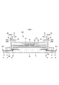
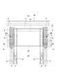
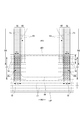
- the tensile force when the lower end portion 14 of the front exterior body 12F and the lower end portion 14 of the rear exterior body 12B are respectively extended to the elastic limit in the width direction WD and then contracted to the size of 3/4 thereof is as follows. Measure according to the procedure. (1) As shown in FIG. 18A, the side seal 12A is peeled off to bring both side portions of the front exterior body 12F and both side portions of the rear exterior body 12B into a separated deployed state, and then the front exterior body is separated.
- the lower end portion 14 of the front exterior body 12F and the lower end portion 14 of the rear exterior body 12B are cut off, and the absorber 56 is removed as much as possible to form the test piece 14F of the lower end portion 14 of the front exterior body 12F and the lower end portion 14 of the rear exterior body 12B.
- a test piece 14B is prepared. In the test pieces 14F and 14B, a portion 200c of the interior body 200 other than the absorber 56 remains.
- test piece 14F at the lower end 14 of the front exterior body 12F is kept in parallel with one side seal 12A and the other side seal 12A, and has an elastic limit in the width direction (the elastic region around the waist is flat without shrinkage or slack).
- the dimension d2 in the width direction between the side seal portions 12A at the elastic limit is measured with a ruler. Since the latter dimension d2 is the same for the test piece 14F at the lower end 14 of the front exterior body 12F and the test piece 14B at the lower end 14 of the rear exterior body 12B, it is sufficient to measure only one of them.
- the chuck-to-chuck distance Dc becomes d2 (elastic limit) at a tensile speed of 300 mm / min.
- the inter-chuck distance Dc is shortened, and the tensile force when the test piece 14F is contracted until the inter-chuck distance Dc becomes 3/4 of d2 is measured, and this tensile force is used as the front exterior body 12F. It is a measured value of the tensile force when the lower end portion 14 of the above is extended to the elastic limit in the width direction WD and then contracted to the dimension of 3/4 of the extension.
- test piece 14B at the lower end portion 14 of the rear exterior body 12B perform (2) to (4) in the same manner as in the case of the front exterior body 12F, and make the lower end portion 14 of the rear exterior body 12B WD in the width direction.
- the tensile force when the body is stretched to the elastic limit and then contracted to the size of 3/4 of the stretch is measured.
- the distance Dc between chucks is measured using a ruler.
- the number, thickness, spacing, material type, arrangement of LDs in the front-rear direction, and maximum elongation rate of the elastic members 16 to 19 in the front exterior body 12F and the rear exterior body 12B At least one of can be different.
- most of the general pants-type disposable diapers have the same width WD dimensions of the front exterior body 12F and the width direction WD of the rear exterior body 12B as shown in the illustrated example.
- the 12F and the rear exterior body 12B have natural lengths, they are contracted in the width direction WD by the elastic members 16 to 19, and can be extended in the width direction WD by this contraction amount.
- the simplest way is to make the number, thickness, spacing, material type, and arrangement of the LDs in the front-rear direction the same in the front exterior body 12F and the rear exterior body 12B, and the maximum elongation rate. If the front exterior body 12F is made larger than the rear exterior body 12B, the above-mentioned difference in tensile force can be created.
- the number of elastic members 16 to 19 is increased in the front exterior body 12F than in the rear exterior body 12B, and other conditions are common to the front exterior body 12F and the rear exterior body 12B, and the thickness of the elastic members is set.
- the front exterior body 12F may be thicker than the rear exterior body 12B, and other conditions may be common to the front exterior body 12F and the rear exterior body 12B.
- the difference in tensile force between the lower end portion 14 of the front exterior body 12F and the lower end portion 14 of the rear exterior body 12B may be appropriately determined, but usually, the lower end portion 14 of the front exterior body is set to the elastic limit in the width direction WD.
- the tensile force when contracted to the 3/4 size after stretching caused the lower end 14 of the rear exterior body to stretch to the elastic limit in the width direction WD and then shrink to the 3/4 size. It is preferably 1.3 to 3.0 times, particularly 1.5 to 2.0 times the tensile force at the time.
- the width direction WD dimension (expanded state) of the post-joining region 70B can be appropriately determined, but in order to secure the covering range of the buttocks as wide as possible, the width direction WD dimension (expanded state) of the side flap 70 is 0. It is preferably 8 to 1 times. Further, the dimension (deployed state) of the front-rear LD in the rear-joining region 70B is preferably equal to or larger than the dimension of the front-rear LD in the region where the side flap 70 and the waist-circumferential expansion / contraction region A2 of the rear exterior body 12B overlap. It is preferable that the size is less than the dimension of the front-rear LD in the region where the exterior body 12B and the side flap 70 overlap.
- the front exterior body 12F and the rear exterior body 12B must have the same rectangular shape in the front-rear direction LD and the width direction WD. Is preferable.
- the appropriate front-rear direction LD dimensions of the front exterior body 12F and the rear exterior body 12B are 0.2 to 0.4 times the total length Y of the product.
- the covering property of the buttocks is lowered only by the rear exterior body 12B, but the covering property of the buttocks can be supplemented by the side flap 70 of the interior body 200 described above.
- the back surfaces of the left and right side flaps 70 are joined to the portion overlapping the front exterior body 12F via the hot melt adhesive HM, and the left and right sides are joined. It is preferable that the flap 70 has a pre-bonding region 70F joined to a portion including the lower end portion 14 of the front exterior body 12F. In this case, the front joint region 70F of the side flap 70 contracts in the width direction WD together with the waist circumference expansion / contraction region A2 of the front exterior body 12F in the state of natural length (before mounting).
- the tensile force when the lower end portion 14 of the front exterior body is extended to the elastic limit in the width direction WD and then contracted to the dimension of 3/4 thereof is the lower end portion of the rear exterior body. If it is larger than the tensile force when 14 is extended to the elastic limit in the width direction WD and then contracted to the size of 3/4 of the elastic limit, the rear exterior body 12B is larger than the lower end portion 14 of the front exterior body 12F in the mounted state. The lower end portion 14 of the is largely extended in the width direction WD (extended longer). As a result, as shown in FIG.
- the pre-joining region 70F of the side flap 70 expands in the width direction WD, it does not expand more than the post-joining region 70B, so that the pre-joining region 70F and the post-joining region 70B expand to the same extent.
- the side flaps 70 will fit more appropriately to the groin as compared to the case of doing so.
- the rear joining region 70B expands more in the width direction WD than the front joining region 70F in the mounted state, so that the side flap 70
- the width of the hollow portion 70H becomes narrower from the rear to the front, the bulge of the hollow portion 70H becomes larger from the back to the front, and the fit to the inguinal region is also improved.
- the size of the width direction WD of the front joining area 70F is preferably the same as the size of the width direction WD of the back joining area 70B, but it may be shorter or longer. Further, the dimension (deployed state) of the front-rear direction LD of the front joining region 70F is preferably equal to or larger than the dimension of the front-rear direction LD of the region where the side flap 70 and the waist circumference expansion / contraction region A2 of the front exterior body 12F overlap. It is preferable that the size is less than the dimension of the front-rear LD in the region where the exterior body 12F and the side flap 70 overlap.
- Non-woven fabric As the non-woven fabric in the above description, a known non-woven fabric can be appropriately used depending on the site and purpose.
- the constituent fibers of the non-woven fabric include olefin-based fibers such as polyethylene and polypropylene, polyester-based and polyamide-based synthetic fibers (including single-component fibers and composite fibers such as core sheaths), as well as recycled rayon and cupra. Fibers, natural fibers such as cotton, and the like can be selected without particular limitation, and these can be mixed and used. In order to increase the flexibility of the non-woven fabric, it is preferable that the constituent fibers are crimped fibers.
- the constituent fibers of the non-woven fabric include hydrophobic fibers or water-repellent fibers (including fibers made water-repellent by the water-repellent agent) even if they are hydrophilic fibers (including fibers made hydrophilic by the hydrophilic agent). ) May be.
- the non-woven fabric generally has a short fiber non-woven fabric, a long fiber non-woven fabric, a spunbond non-woven fabric, a melt blown non-woven fabric, a spunlace non-woven fabric, a thermal bond (air-through) non-woven fabric, and a needle punch depending on the fiber length, the sheet forming method, the fiber bonding method, and the laminated structure.
- non-woven fabrics It is classified into non-woven fabrics, point-bonded non-woven fabrics, laminated non-woven fabrics (SMS non-woven fabrics having a melt blown layer sandwiched between spunbond layers, SMMS non-woven fabrics, etc.), and any of these non-woven fabrics can be used.
- SMS non-woven fabrics having a melt blown layer sandwiched between spunbond layers, SMMS non-woven fabrics, etc.
- the "front-back direction” means the direction indicated by the symbol LD in the figure (vertical direction), and the “width direction” means the direction indicated by the WD in the figure (horizontal direction), and the front-back direction and the width direction. Are orthogonal.
- Front side means the side of the member that is closer to the wearer's skin when wearing a pants-type disposable diaper
- back side means the side of the member that is closer to the wearer's skin when wearing a pants-type disposable diaper. It means the far side.
- Elongation rate means the value when the natural length is 100%. For example, an elongation rate of 200% is synonymous with an elongation ratio of 2 times.
- Maximum elongation rate means the elongation rate when stretched to the elastic limit (in other words, the stretch rate in the expanded state in which the stretchable region is flatly expanded without shrinkage or slack).
- Methodsuke is measured as follows. After pre-drying the sample or test piece, leave it in a test room or device under standard conditions (test location: temperature 23 ⁇ 1 ° C., relative humidity 50 ⁇ 2%) to bring it to a constant weight. Pre-drying refers to making a sample or test piece constant in an environment at a temperature of 100 ° C. It is not necessary to pre-dry the fibers having an official moisture content of 0.0%. A sample having a size of 100 mm ⁇ 100 mm is cut out from the test piece in a constant weight state using a sampling template (100 mm ⁇ 100 mm). The weight of the sample is measured and multiplied by 100 to calculate the weight per square meter, which is used as the basis weight.
- the "thickness" is automatically measured using an automatic thickness measuring device (KES-G5 handy compression measurement program) under the conditions of a load of 0.098 N / cm 2 and a pressurized area of 2 cm 2.
- KS-G5 handy compression measurement program automatic thickness measuring device
- the water absorption rate shall be the "time to the end point" when JIS K7224-1996 "Water absorption rate test method for highly water-absorbent resin" was performed using 2 g of highly absorbent polymer and 50 g of physiological saline. ..
- Unfolded state means a state in which it is unfolded flat without shrinkage or slack.
- the dimensions of each part mean the dimensions in the unfolded state, not in the natural length state.
- test or measurement shall be performed in a test room or equipment under standard conditions (test location: temperature 23 ⁇ 1 ° C, relative humidity 50 ⁇ 2%). To do.
- the present invention can be used for pants-type disposable diapers as in the above example.
Abstract
[Problem] To improve the ability of covering buttocks. [Solution] In order to solve the above problem: a front exterior body 12F and a back exterior body 12B each have a waist-area stretch region A2 that is elastically stretchable in the width direction WD; an interior body 200 has side flaps 70 each having a side stretch region SG elastically stretchable in the longitudinal direction LD; the side flaps 70 have back joining regions 70B that are joined with the lower end part 14 of the back exterior body 12B; the back joining regions 70B are, together with the waist area stretch region A2 of the back exterior body 12B, shrunk in the width direction WD, and are stretchable in the width direction WD; and the tensile strength of the back exterior body 12B obtained by stretching the lower end part 14 in the width direction WD to the elasticity limit thereof and then shrinking the same to a 3/4 size thereof is less than that of the front exterior body 12F.
Description
本発明は、臀部の被覆性を改善した、外装二分割構造のパンツタイプ使い捨ておむつに関するものである。
The present invention relates to a pants-type disposable diaper having a two-part exterior structure with improved buttock coverage.
外装二分割構造のパンツタイプ使い捨ておむつは、前身頃の少なくとも胴周り部を構成する前外装体及び後身頃の少なくとも胴周り部を構成する後外装体と、前外装体から後外装体にわたるように外装体に対して取り付けられた、吸収体を含む内装体とを備え、前外装体の両側部と後外装体の両側部とが接合されてサイドシールが形成されることにより、ウエスト開口及び左右一対の脚開口が形成されたものである(例えば特許文献1参照)。
Pants-type disposable diapers with a two-piece exterior structure are such that the front exterior body that constitutes at least the waist circumference of the front body, the rear exterior body that constitutes at least the waist circumference of the back body, and the front exterior body to the rear exterior body. It is provided with an interior body including an absorber attached to the exterior body, and both sides of the front exterior body and both sides of the rear exterior body are joined to form a side seal, whereby the waist opening and the left and right sides are formed. A pair of leg openings are formed (see, for example, Patent Document 1).
このようなパンツタイプ使い捨ておむつでは、身体へのフィット性を向上させるために、前外装体及び後外装体に伸縮構造を設けることが一般的となっている。例えば、サイドシールと対応する前後方向範囲として定まる胴周り領域や、前後の胴周り領域の間に位置する中間領域に、幅方向に伸縮する伸縮領域を設けたものは身体に対するフィット性が比較的に高いものとなっている。
In such pants-type disposable diapers, it is common to provide elastic structures on the front and rear exteriors in order to improve the fit to the body. For example, a waist area that is defined as a range in the front-rear direction corresponding to the side seal, or an intermediate area that is located between the front and rear waist areas and has a stretchable area that expands and contracts in the width direction has a relatively good fit to the body. It is expensive.
他方、外装二分割タイプのパンツタイプ使い捨ておむつでは、脚開口のフィット性が低下せざるをえない。すなわち、外装二分割タイプのパンツタイプ使い捨ておむつは、装着時に内装体の股下部にあたる位置から内装体と外装体との交差位置までの距離が長いため、交差位置を支点として内装体が左右に振られやすいことにより、前身頃から後身頃まで連続する一体的な外装体を備えるタイプと比較して内装体が横方向に動きやすい。また、外装二分割タイプのパンツタイプ使い捨ておむつは、外装体の股間側の縁が幅方向に沿う直線状又はそれに近い形状となっており、内装体の側縁と直角又はそれに近い角度で交差する。これらは、脚開口の縁部のうち、内装体の側縁と外装体の股間側の縁との交差位置近傍におけるフィット性が不足しがちであることを意味する。
On the other hand, with the pants-type disposable diaper that is divided into two parts, the fit of the leg opening has to be reduced. That is, since the distance from the position corresponding to the inseam of the interior body to the intersection position between the interior body and the exterior body is long in the pants-type disposable diaper of the exterior two-piece type, the interior body swings left and right with the intersection position as a fulcrum. Because it is easy to handle, the interior body is easier to move in the lateral direction compared to the type that has an integrated outer body that is continuous from the front body to the back body. In addition, the pants-type disposable diaper of the exterior two-piece type has a shape in which the crotch-side edge of the exterior body is straight or close to the width direction, and intersects the side edge of the interior body at a right angle or an angle close to it. .. These mean that, among the edges of the leg openings, the fit tends to be insufficient in the vicinity of the intersection position between the side edge of the interior body and the crotch side edge of the exterior body.
これに対して、内装体の両側部に、起き上がりギャザーよりも側方に延び出たサイドフラップが、前外装体から後外装体まで前後方向に延びており、サイドフラップは、前後方向に弾性伸縮するサイド伸縮領域を有していると、サイド伸縮領域が内装体の横移動を弾性的に支えること、及びサイド伸縮領域が内装体の横をカバーすることにより、内装体の横に隙間が生じにくくなるため好ましい。
On the other hand, on both sides of the interior body, side flaps extending laterally from the rising gathers extend in the front-rear direction from the front exterior body to the rear exterior body, and the side flaps elastically expand and contract in the front-rear direction. When the side expansion / contraction area is provided, the side expansion / contraction area elastically supports the lateral movement of the interior body, and the side expansion / contraction area covers the side of the interior body, so that a gap is generated on the side of the interior body. It is preferable because it becomes difficult.
ここで、サイド伸縮領域のフィット性を十分に発揮させるためには、内装体と外装体とが接合された内外接合部は、サイドフラップまで及んでいることが好ましい。
Here, in order to fully exert the fit of the side expansion / contraction region, it is preferable that the inner / outer joint portion where the interior body and the exterior body are joined extends to the side flap.
しかし、内外接合部に、外装体の伸縮領域と内装体のサイド伸縮領域との重なり部分を有すると、内装体のサイドフラップが幅方向に収縮してしまい、サイドフラップによるカバー幅が狭くなってしまう。特に後身頃で内装体のサイドフラップによるカバー幅が狭くなると、臀部を広範囲にカバーできないために、内装体が臀裂に食い込みやすくなるという問題点がある。
However, if the inner / outer joint portion has an overlapping portion between the expansion / contraction region of the exterior body and the side expansion / contraction region of the interior body, the side flaps of the interior body contract in the width direction, and the cover width by the side flaps becomes narrow. It ends up. In particular, if the width of the cover by the side flaps of the interior body is narrowed at the back body, there is a problem that the interior body easily bites into the intergluteal cleft because the buttocks cannot be covered over a wide area.
そこで、本発明の主たる課題は、臀部の被覆性を改善すること等にある。
Therefore, the main subject of the present invention is to improve the covering property of the buttocks and the like.
上記課題を解決したパンツタイプ使い捨ておむつは以下のとおりである。
<第1の態様>
前身頃の少なくとも胴周り部を構成する前外装体、及び後身頃の少なくとも胴周り部を構成する後外装体と、
前記前外装体から前記後外装体にわたり設けられた、吸収体を含む内装体と、
前記内装体と、前記前外装体及び前記後外装体とがそれぞれ接合された内外接合部と、
前記前外装体の両側部と前記後外装体の両側部とがそれぞれ接合されたサイドシールと、
ウエスト開口及び左右一対の脚開口とを備え、
前記前外装体及び前記後外装体は、前記サイドシールを有する前後方向範囲を前後方向に四等分したときの最も脚開口側の部分として定義される下端部を含む、幅方向に弾性伸縮する胴周り伸縮領域を有しており、
前記内装体の両側部には、前記吸収体よりも側方に延び出たサイドフラップが、前記前外装体から前記後外装体まで前後方向に延びており、
前記サイドフラップは、少なくとも前記前外装体と重なる部分と前記後外装体と重なる部分との間の部分に、前後方向に弾性伸縮するサイド伸縮領域を有しており、
前記後外装体の胴周り伸縮領域は、少なくとも左右の前記サイドフラップと重なる部分に設けられており、
左右の前記サイドフラップは、前記後外装体の下端部を含む部分と接合された後接合領域を有し、
前記後接合領域は、前記後外装体の胴周り伸縮領域とともに、幅方向に収縮しているとともに、幅方向に伸長可能であり、
前記前外装体の下端部を、幅方向に弾性限界まで伸長してからその3/4の寸法に収縮させたときの引張力が、前記後外装体の下端部を、幅方向に弾性限界まで伸長してからその3/4の寸法に収縮させたときの引張力よりも大きい、
ことを特徴とするパンツタイプ使い捨ておむつ。 The pants-type disposable diapers that solve the above problems are as follows.
<First aspect>
The front exterior body that constitutes at least the waist circumference of the front body, and the rear exterior body that constitutes at least the waist circumference of the back body,
An interior body including an absorber provided from the front exterior body to the rear exterior body, and
An inner / outer joint portion to which the interior body, the front exterior body, and the rear exterior body are joined, respectively.
A side seal in which both side portions of the front exterior body and both side portions of the rear exterior body are joined, respectively.
With a waist opening and a pair of left and right leg openings
The front exterior body and the rear exterior body elastically expand and contract in the width direction including the lower end portion defined as the most leg opening side portion when the front-rear direction range having the side seal is divided into four equal parts in the front-rear direction. It has a stretchable area around the waist and
On both sides of the interior body, side flaps extending laterally from the absorber extend in the front-rear direction from the front exterior body to the rear exterior body.
The side flap has a side elastic region that elastically expands and contracts in the front-rear direction at least in a portion between a portion that overlaps the front exterior body and a portion that overlaps the rear exterior body.
The elastic region around the waist of the rear exterior body is provided at least in a portion overlapping the left and right side flaps.
The left and right side flaps have a post-joining region joined with a portion including the lower end of the rear exterior body.
The post-joining region is contracted in the width direction and is expandable in the width direction together with the elastic region around the waist of the rear exterior body.
The tensile force when the lower end of the front exterior body is extended to the elastic limit in the width direction and then contracted to the dimension of 3/4 of the extension causes the lower end of the rear exterior body to reach the elastic limit in the width direction. It is larger than the tensile force when it is stretched and then shrunk to its 3/4 size.
Pants-type disposable diapers that feature this.
(作用効果)
本パンツタイプ使い捨ておむつでは、サイドフラップの後接合領域は、自然長(装着前)の状態では、後外装体の胴周り伸縮領域とともに幅方向に収縮している。ここで、本パンツタイプ使い捨ておむつでは、前外装体の下端部を、幅方向に弾性限界まで伸長してからその3/4の寸法に収縮させたときの引張力が、後外装体の下端部を、幅方向に弾性限界まで伸長してからその3/4の寸法に収縮させたときの引張力よりも大きいため、装着状態では前外装体の下端部よりも後外装体の下端部が大きく幅方向に伸長される(より長く伸長される)。この結果、サイドフラップの後接合領域はより幅方向に大きく展開し、サイドフラップが臀部をより広範囲に被覆し、内装体は臀裂に食い込みにくくなる。
なお、「幅方向に弾性限界まで伸長してからその3/4の寸法に収縮させたときの引張力」は、一般的なパンツタイプ使い捨ておむつにおいて、適合寸法の装着者が装着したときの状態を想定したものである。 (Action effect)
In this pants-type disposable diaper, the rear joint region of the side flap contracts in the width direction together with the elastic region around the waist of the rear exterior body in the state of natural length (before wearing). Here, in this pants type disposable diaper, the tensile force when the lower end of the front exterior body is extended to the elastic limit in the width direction and then contracted to the dimension of 3/4 of that is the lower end portion of the rear exterior body. Is larger than the tensile force when it is stretched to the elastic limit in the width direction and then contracted to the dimension of 3/4 of that, so that the lower end of the rear exterior body is larger than the lower end of the front exterior body in the mounted state. Stretched in the width direction (stretched longer). As a result, the posterior junction region of the side flaps expands more in the width direction, the side flaps cover the buttocks more extensively, and the interior body is less likely to bite into the intergluteal cleft.
The "tensile force when the diaper is stretched to the elastic limit in the width direction and then contracted to the dimension of 3/4" is the state when the wearer of the conforming size wears the general pants type disposable diaper. Is assumed.
<第2の態様>
前記前外装体の下端部を、幅方向に弾性限界まで伸長してからその3/4の寸法に収縮させたときの引張力が、前記後外装体の下端部を、幅方向に弾性限界まで伸長してからその3/4の寸法に収縮させたときの引張力の1.3~3.0倍である、
第1の態様のパンツタイプ使い捨ておむつ。 <Second aspect>
The tensile force when the lower end of the front exterior body is extended to the elastic limit in the width direction and then contracted to the dimension of 3/4 of the extension causes the lower end of the rear exterior body to reach the elastic limit in the width direction. It is 1.3 to 3.0 times the tensile force when it is stretched and then shrunk to its 3/4 size.
The pants-type disposable diaper of the first aspect.
(作用効果)
前外装体の下端部及び後外装体の下端部の引張力の差は適宜定めればよいが、通常の場合、本態様の範囲内であることが好ましい。 (Action effect)
The difference in tensile force between the lower end portion of the front exterior body and the lower end portion of the rear exterior body may be appropriately determined, but is usually preferably within the range of this embodiment.
<第3の態様>
前記後接合領域の幅方向の寸法は、前記サイドフラップの幅方向の寸法の0.8~1倍である、
第1又は2の態様のパンツタイプ使い捨ておむつ。 <Third aspect>
The widthwise dimension of the post-joining region is 0.8 to 1 times the widthwise dimension of the side flaps.
Pants-type disposable diaper according to the first or second aspect.
前記後接合領域の幅方向の寸法は、前記サイドフラップの幅方向の寸法の0.8~1倍である、
第1又は2の態様のパンツタイプ使い捨ておむつ。 <Third aspect>
The widthwise dimension of the post-joining region is 0.8 to 1 times the widthwise dimension of the side flaps.
Pants-type disposable diaper according to the first or second aspect.
(作用効果)
後接合領域の幅方向の寸法は適宜定めることができるが、十分に広いことが好ましく、通常の場合、本態様の範囲内であると好ましい。 (Action effect)
The width direction of the post-joining region can be appropriately determined, but it is preferably sufficiently wide, and usually, it is preferably within the range of this embodiment.
後接合領域の幅方向の寸法は適宜定めることができるが、十分に広いことが好ましく、通常の場合、本態様の範囲内であると好ましい。 (Action effect)
The width direction of the post-joining region can be appropriately determined, but it is preferably sufficiently wide, and usually, it is preferably within the range of this embodiment.
<第4の態様>
前記前外装体及び前記後外装体は、前後方向の寸法及び幅方向の寸法が同じ長方形であり、
前記前外装体及び前記後外装体の前後方向の寸法が、製品全長の0.2~0.4倍である、
第1~3のいずれか1つの態様のパンツタイプ使い捨ておむつ。 <Fourth aspect>
The front exterior body and the rear exterior body are rectangular in which the dimensions in the front-rear direction and the dimensions in the width direction are the same.
The dimensions of the front exterior body and the rear exterior body in the front-rear direction are 0.2 to 0.4 times the total length of the product.
A pants-type disposable diaper according to any one of the first to third aspects.
(作用効果)
外装体の素材使用量を低減し、簡素な構造とするためには、前外装体及び後外装体は、前後方向の寸法及び幅方向の寸法が同じ長方形であることが好ましい。このような設計では、前外装体及び後外装体の適切な前後方向の寸法は、製品全長の0.2~0.4倍となる。この場合、後外装体だけでは臀部の被覆性が低下するが、前述の内装体のサイドフラップにより臀部の被覆性を補うことができる。 (Action effect)
In order to reduce the amount of material used for the exterior body and to have a simple structure, it is preferable that the front exterior body and the rear exterior body are rectangular in which the dimensions in the front-rear direction and the dimensions in the width direction are the same. In such a design, the appropriate front-rear dimensions of the front and rear exteriors are 0.2 to 0.4 times the overall length of the product. In this case, the covering property of the buttocks is lowered only by the rear exterior body, but the covering property of the buttocks can be supplemented by the side flap of the interior body described above.
<第5の態様>
前記前外装体の胴周り伸縮領域は、少なくとも左右の前記サイドフラップと重なる部分に設けられており、
左右の前記サイドフラップは、前記前外装体の下端部を含む部分と接合された前接合領域を有し、
前記前接合領域は、前記前外装体の胴周り伸縮領域とともに、幅方向に収縮しているとともに、幅方向に伸長可能である、
第1~4のいずれか1つの態様のパンツタイプ使い捨ておむつ。 <Fifth aspect>
The elastic region around the waist of the front exterior body is provided at least in a portion overlapping the left and right side flaps.
The left and right side flaps have a front joining region joined to a portion including the lower end of the front exterior body.
The front joint region is contracted in the width direction and is expandable in the width direction together with the elastic region around the waist of the front exterior body.
A pants-type disposable diaper according to any one of the first to fourth aspects.
(作用効果)
本パンツタイプ使い捨ておむつでは、サイドフラップの前接合領域は、自然長(装着前)の状態では、前外装体の胴周り伸縮領域とともに幅方向に収縮している。ここで、本パンツタイプ使い捨ておむつでは、前外装体の下端部を、幅方向に弾性限界まで伸長してからその3/4の寸法に収縮させたときの引張力が、後外装体の下端部を、幅方向に弾性限界まで伸長してからその3/4の寸法に収縮させたときの引張力よりも大きいため、装着状態では前外装体の下端部よりも後外装体の下端部が大きく幅方向に伸長される(より長く伸長される)。この結果、サイドフラップの前接合領域は幅方向に展開するものの、後接合領域よりは展開しないため、前接合領域及び後接合領域が同程度展開する場合と比較して、サイドフラップが鼠径部に対してより適切にフィットする。
<第6の態様>
前記サイド伸縮領域は、前記サイドフラップに、一本又は複数本の細長状のサイド弾性部材が前後方向に沿ってかつ互いに間隔を空けて設けられた領域であり、
前記サイドフラップは、その側縁に沿って前接合領域から前記後接合領域まで前後方向に続く中空部を有しており、
前記サイド弾性部材の収縮により、前記サイドフラップにおける前記中空部を含む部分が前後方向に収縮してサイドギャザーが形成されている、
第1~5のいずれか1つの態様のパンツタイプ使い捨ておむつ。 (Action effect)
In this pants-type disposable diaper, the front joint area of the side flap contracts in the width direction together with the elastic area around the waist of the front exterior body in the state of natural length (before wearing). Here, in this pants type disposable diaper, the tensile force when the lower end of the front exterior body is extended to the elastic limit in the width direction and then contracted to the dimension of 3/4 of that is the lower end portion of the rear exterior body. Is larger than the tensile force when it is stretched to the elastic limit in the width direction and then contracted to the dimension of 3/4 of that, so that the lower end of the rear exterior body is larger than the lower end of the front exterior body in the mounted state. Stretched in the width direction (stretched longer). As a result, although the pre-joining region of the side flap expands in the width direction, it does not expand more than the post-joining region, so that the side flap expands to the inguinal region as compared with the case where the pre-joining region and the post-joining region expand to the same extent. On the other hand, it fits better.
<Sixth aspect>
The side expansion / contraction region is a region in which one or a plurality of elongated side elastic members are provided on the side flap along the front-rear direction and at intervals from each other.
The side flap has a hollow portion extending in the front-rear direction from the front joining region to the back joining region along its side edge.
Due to the contraction of the side elastic member, the portion of the side flap including the hollow portion contracts in the front-rear direction to form side gathers.
A pants-type disposable diaper according to any one of the first to fifth aspects.
(作用効果)
本使い捨て着用物品では、サイド弾性部材の収縮により、サイドフラップに沿う中空部を含む部分が前後方向に収縮してサイドギャザーの各襞が前後方向に並んで形成される。ここで、サイドフラップにおける中空部を含む部分にサイドギャザーが形成されると、サイドギャザーの襞は中空部が大きく膨らむことにより形成され、大きく柔らか(つまりクッション性に富む)なものとなる。したがって、この大きく柔らかな襞により、股間部の側部の肌触りが良好となる(ふっくら、ふわふわしたものとなる)。
特に、前述のように、装着状態では前外装体の胴周り伸縮領域よりも後外装体の胴周り伸縮領域が大きく幅方向に伸長し(より長く伸長し)、サイドフラップの後接合領域は幅方向により大きく展開するため、中空部の膨らみは後接合領域に向かうにつれて平坦に近くなり、臀部に対するフィット性が良好となる。
さらに、第6の態様の場合、サイドフラップの幅は、後から前に向かうにつれて狭くなり、中空部の膨らみは後ろから前に向かうにつれて大きくなるため、鼠径部に対するフィット性も特に良好となる。 (Action effect)
In this disposable wearable article, due to the contraction of the side elastic member, the portion including the hollow portion along the side flap contracts in the front-rear direction, and the folds of the side gathers are formed side by side in the front-rear direction. Here, when side gathers are formed in the portion of the side flap including the hollow portion, the folds of the side gathers are formed by the hollow portion greatly swelling, and become large and soft (that is, rich in cushioning property). Therefore, this large and soft fold makes the side of the crotch feel good (it becomes fluffy and fluffy).
In particular, as described above, in the mounted state, the elastic region around the waist of the rear exterior body extends in the width direction (extends longer) than the elastic region around the waist of the front exterior body, and the rear joining region of the side flaps extends in width. Since it expands more in the direction, the bulge of the hollow portion becomes closer to flat toward the post-joining region, and the fit to the buttocks becomes better.
Further, in the case of the sixth aspect, the width of the side flap becomes narrower from the rear to the front, and the bulge of the hollow portion becomes larger from the back to the front, so that the fit to the inguinal region is particularly good.
本発明によれば、臀部の被覆性が改善される、等の利点がもたらされる。
According to the present invention, there are advantages such as improved coverage of the buttocks.
以下、パンツタイプ使い捨ておむつの一例について、添付図面を参照しつつ詳説する。断面図における点模様部分はその表側及び裏側に位置する各構成部材を接合する接合手段としての接着剤を示しており、ホットメルト接着剤のベタ、ビード、カーテン、サミット若しくはスパイラル塗布、又はパターンコート(凸版方式でのホットメルト接着剤の転写)などにより、あるいは弾性部材の固定部分はこれに代えて又はこれとともにコームガンやシュアラップ塗布などの弾性部材の外周面への塗布により形成されるものである。ホットメルト接着剤としては、例えばEVA系、粘着ゴム系(エラストマー系)、オレフィン系、ポリエステル・ポリアミド系などの種類のものが存在するが、特に限定無く使用できる。各構成部材を接合する接合手段としてはヒートシールや超音波シール等の素材溶着による手段を用いることもできる。
Below, an example of a pants-type disposable diaper will be explained in detail with reference to the attached drawings. The dotted pattern portion in the cross-sectional view shows an adhesive as a joining means for joining the constituent members located on the front side and the back side thereof, and is a solid, bead, curtain, summit or spiral coating of hot melt adhesive, or pattern coating. (Transfer of hot melt adhesive by letterpress method) or the fixed part of the elastic member is formed by coating the elastic member on the outer peripheral surface of the elastic member such as comb gun or sure wrap coating instead of or together with this. is there. Examples of the hot melt adhesive include EVA type, adhesive rubber type (elastomer type), olefin type, polyester / polyamide type and the like, but they can be used without particular limitation. As a joining means for joining each component, a means by material welding such as a heat seal or an ultrasonic seal can also be used.
図1~図6は、パンツタイプ使い捨ておむつの一例を示している。本パンツタイプ使い捨ておむつは、前身頃Fの少なくとも胴周り部を構成する長方形の前外装体12F及び後身頃Bの少なくとも胴周り部を構成する長方形の後外装体12Bと、前外装体12Fから股間部を経て後外装体12Bまで延在するように外装体12F,12Bに設けられた内装体200とを備えている。前外装体12Fの両側部と後外装体12Bの両側部とが接合されてサイドシール12Aが形成されており、これにより、外装体12F,12Bの前後端部により形成される開口が装着者の胴を通すウエスト開口WOとなり、内装体200の幅方向両側において外装体12F,12Bの下縁及び内装体200の側縁によりそれぞれ囲まれる部分が脚を通す脚開口LOとなっている。内装体200は、尿等の排泄物等を吸収保持する部分であり、外装体12F,12Bは着用者の身体に対して内装体200を支えるための部分である。また、符号Yは展開状態におけるおむつの全長(前身頃Fのウエスト開口WOの縁から後身頃Bのウエスト開口WOの縁までの前後方向長さ)を示しており、符号Xは展開状態におけるおむつの全幅を示している。
FIGS. 1 to 6 show an example of a pants-type disposable diaper. This pants-type disposable diaper has a rectangular front exterior body 12F that constitutes at least the waist circumference of the front body F, a rectangular rear exterior body 12B that constitutes at least the waist circumference of the back body B, and a crotch from the front exterior body 12F. It is provided with an interior body 200 provided on the exterior bodies 12F and 12B so as to extend through the portion to the rear exterior body 12B. Both side portions of the front exterior body 12F and both side portions of the rear exterior body 12B are joined to form a side seal 12A, whereby an opening formed by the front and rear ends of the exterior bodies 12F and 12B is formed by the wearer. The waist opening WO through which the body passes, and the portions surrounded by the lower edges of the exterior bodies 12F and 12B and the side edges of the interior body 200 on both sides in the width direction of the interior body 200 are leg openings LO through which the legs pass. The interior body 200 is a part that absorbs and holds excrement such as urine, and the exterior bodies 12F and 12B are parts for supporting the interior body 200 with respect to the wearer's body. Further, the reference numeral Y indicates the total length of the diaper in the unfolded state (the length in the front-rear direction from the edge of the waist opening WO of the front body F to the edge of the waist opening WO of the rear body B), and the reference numeral X indicates the diaper in the unfolded state. Shows the full width of.
本パンツタイプ使い捨ておむつは、サイドシール12Aを有する前後方向範囲(ウエスト開口WOから脚開口LOの上端に至る前後方向範囲)として定まる胴周り領域Tと、脚開口LOを形成する部分の前後方向範囲(前身頃Fのサイドシール12Aを有する前後方向領域と後身頃Bのサイドシール12Aを有する前後方向領域との間)として定まる中間領域Lとを有する。胴周り領域Tは、概念的にウエスト開口の縁部を形成する「ウエスト部」Wと、これよりも下側の部分である「ウエスト下方部」Uとに分けることができる。通常、胴周り領域T内に幅方向WDの伸縮応力が変化する境界(例えば弾性部材の太さや伸長率が変化する)を有する場合は、最もウエスト開口WO側の境界よりもウエスト開口WO側がウエスト部Wとなり、このような境界が無い場合は吸収体56又は内装体200よりもウエスト開口WO側に延び出たウエスト延出部分12Eがウエスト部Wとなる。これらの前後方向長さは、製品のサイズによって異なり、適宜定めることができるが、一例を挙げると、ウエスト部Wは15~40mm、ウエスト下方部Uは65~120mmとすることができる。一方、中間領域Lの両側縁は被着者の脚周りに沿うようにコ字状又は曲線状に括れており、ここが装着者の脚を入れる部位となる。この結果、展開状態のパンツタイプ使い捨ておむつは、全体としてほぼ砂時計形状をなしている。
This pants type disposable diaper has a waist circumference region T defined as a front-rear direction range having a side seal 12A (a front-rear direction range from the waist opening WO to the upper end of the leg opening LO) and a front-back direction range of a portion forming the leg opening LO. It has an intermediate region L defined as (between the front-rear region having the side seal 12A of the front body F and the front-rear region having the side seal 12A of the back body B). The waist circumference region T can be divided into a "waist portion" W that conceptually forms an edge portion of the waist opening and a "waist lower portion" U that is a portion below the waist portion. Normally, when there is a boundary in the waist circumference region T where the tensile stress in the width direction changes (for example, the thickness and elongation rate of the elastic member change), the waist opening WO side is the waist rather than the boundary on the waist opening WO side. If there is no such boundary, the waist extending portion 12E extending toward the waist opening WO side from the absorber 56 or the interior body 200 becomes the waist portion W. These lengths in the front-rear direction vary depending on the size of the product and can be appropriately determined. For example, the waist portion W can be 15 to 40 mm and the waist lower portion U can be 65 to 120 mm. On the other hand, both side edges of the intermediate region L are constricted in a U-shape or a curved shape along the circumference of the wearer's legs, and this is a portion for inserting the wearer's legs. As a result, the unfolded pants-type disposable diaper has an hourglass shape as a whole.
(内装体)
内装体200は任意の形状を採ることができるが、図示例ではほぼ長方形である。内装体200は、図3~図5に示されるように、身体側となるトップシート30と、液不透過性シート11と、これらの間に介在された吸収要素50とを備えているものであり、吸収機能を担う。符号40は、トップシート30を透過した液を速やかに吸収要素50へ移行させるために、トップシート30と吸収要素50との間に設けられた中間シートを示しており、符号60は、内装体200の両脇に排泄物が漏れるのを防止するために、内装体200の両側部から装着者の脚周りに接するように延び出た起き上がりギャザー60を示している。 (Interior body)
Theinterior body 200 can take any shape, but in the illustrated example, it is substantially rectangular. As shown in FIGS. 3 to 5, the interior body 200 includes a top sheet 30 on the body side, a liquid-impermeable sheet 11, and an absorbing element 50 interposed between them. Yes, it has an absorption function. Reference numeral 40 indicates an intermediate sheet provided between the top sheet 30 and the absorption element 50 in order to quickly transfer the liquid that has passed through the top sheet 30 to the absorption element 50, and reference numeral 60 indicates an interior body. In order to prevent excrement from leaking to both sides of the 200, the rising gathers 60 extending from both sides of the interior body 200 so as to be in contact with the wearer's legs are shown.
内装体200は任意の形状を採ることができるが、図示例ではほぼ長方形である。内装体200は、図3~図5に示されるように、身体側となるトップシート30と、液不透過性シート11と、これらの間に介在された吸収要素50とを備えているものであり、吸収機能を担う。符号40は、トップシート30を透過した液を速やかに吸収要素50へ移行させるために、トップシート30と吸収要素50との間に設けられた中間シートを示しており、符号60は、内装体200の両脇に排泄物が漏れるのを防止するために、内装体200の両側部から装着者の脚周りに接するように延び出た起き上がりギャザー60を示している。 (Interior body)
The
内装体200の幅方向WDの寸法は適宜定めることができるが、例えば吸収体56の幅方向WDの寸法の1~1.5倍とすることができる。
The size of the width direction WD of the interior body 200 can be appropriately determined, but for example, it can be 1 to 1.5 times the size of the width direction WD of the absorber 56.
(トップシート)
トップシート30は、液を透過する性質を有するものであり、例えば、有孔又は無孔の不織布や、多孔性プラスチックシートなどを例示することができる。また、トップシート30は、1枚のシートからなるものであっても、2枚以上のシートを貼り合せて得た積層シートからなるものであってもよい。同様に、トップシート30は、平面方向に関して、1枚のシートからなるものであっても、2枚以上のシートからなるものであってもよい。 (Top sheet)
Thetop sheet 30 has a property of allowing liquid to permeate, and examples thereof include a perforated or non-perforated non-woven fabric and a porous plastic sheet. Further, the top sheet 30 may be made of one sheet or may be made of a laminated sheet obtained by laminating two or more sheets. Similarly, the top sheet 30 may be composed of one sheet or two or more sheets in the plane direction.
トップシート30は、液を透過する性質を有するものであり、例えば、有孔又は無孔の不織布や、多孔性プラスチックシートなどを例示することができる。また、トップシート30は、1枚のシートからなるものであっても、2枚以上のシートを貼り合せて得た積層シートからなるものであってもよい。同様に、トップシート30は、平面方向に関して、1枚のシートからなるものであっても、2枚以上のシートからなるものであってもよい。 (Top sheet)
The
トップシート30の両側部は、吸収要素50の側縁で裏側に折り返しても良く、また折り返さずに吸収要素50の側縁より側方にはみ出させても良い。
Both sides of the top sheet 30 may be folded back on the side edge of the absorbing element 50, or may be projected laterally from the side edge of the absorbing element 50 without being folded back.
トップシート30は、裏側の部材に対する位置ずれを防止する等の目的で、ヒートシール、超音波シールのような素材溶着による接合手段や、ホットメルト接着剤により裏側に隣接する部材に固定することが望ましい。図示例では、トップシート30はその裏面に塗布されたホットメルト接着剤により中間シート40の表面及び包装シート58のうち吸収体56の表側に位置する部分の表面に固定されている。
The top sheet 30 may be fixed to a member adjacent to the back side by a joining means by material welding such as a heat seal or an ultrasonic seal, or by a hot melt adhesive for the purpose of preventing misalignment with respect to the member on the back side. desirable. In the illustrated example, the top sheet 30 is fixed to the surface of the intermediate sheet 40 and the surface of the packaging sheet 58 located on the front side of the absorber 56 by a hot melt adhesive applied to the back surface thereof.
(中間シート)
トップシート30を透過した液を速やかに吸収体へ移行させるために、トップシート30より液の透過速度が速い、中間シート(「セカンドシート」とも呼ばれている)40を設けることができる。この中間シート40は、液を速やかに吸収体56へ移行させて吸収体56による吸収性能を高めるとともに、吸収した液の吸収体56からの逆戻り現象を防止するためのものである。中間シート40は省略することもできる。 (Intermediate sheet)
In order to quickly transfer the liquid that has permeated thetop sheet 30 to the absorber, an intermediate sheet (also referred to as a "second sheet") 40 having a faster liquid permeation speed than the top sheet 30 can be provided. The intermediate sheet 40 is for quickly transferring the liquid to the absorber 56 to improve the absorption performance by the absorber 56 and to prevent the absorbed liquid from returning from the absorber 56. The intermediate sheet 40 may be omitted.
トップシート30を透過した液を速やかに吸収体へ移行させるために、トップシート30より液の透過速度が速い、中間シート(「セカンドシート」とも呼ばれている)40を設けることができる。この中間シート40は、液を速やかに吸収体56へ移行させて吸収体56による吸収性能を高めるとともに、吸収した液の吸収体56からの逆戻り現象を防止するためのものである。中間シート40は省略することもできる。 (Intermediate sheet)
In order to quickly transfer the liquid that has permeated the
中間シート40としては、トップシート30と同様の素材や、スパンレース不織布、スパンボンド不織布、SMS不織布、パルプ不織布、パルプとレーヨンとの混合シート、ポイントボンド不織布又はクレープ紙を例示できる。特にエアスルー不織布が嵩高であるため好ましい。エアスルー不織布には芯鞘構造の複合繊維を用いるのが好ましく、この場合芯に用いる樹脂はポリプロピレン(PP)でも良いが剛性の高いポリエステル(PET)が好ましい。目付けは17~80g/m2が好ましく、25~60g/m2がより好ましい。不織布の原料繊維の太さは2.0~10dtexであるのが好ましい。不織布を嵩高にするために、原料繊維の全部又は一部の混合繊維として、芯が中央にない偏芯の繊維や中空の繊維、偏芯且つ中空の繊維を用いるのも好ましい。
Examples of the intermediate sheet 40 include the same materials as the top sheet 30, spunlace non-woven fabric, spunbonded non-woven fabric, SMS non-woven fabric, pulp non-woven fabric, mixed sheet of pulp and rayon, point-bonded non-woven fabric or crepe paper. In particular, the air-through non-woven fabric is preferable because it is bulky. It is preferable to use a composite fiber having a core-sheath structure for the air-through non-woven fabric. In this case, the resin used for the core may be polypropylene (PP), but polyester (PET) having high rigidity is preferable. Basis weight is preferably 17 ~ 80g / m 2, more preferably 25 ~ 60g / m 2. The thickness of the raw material fiber of the non-woven fabric is preferably 2.0 to 10 dtex. In order to make the non-woven fabric bulky, it is also preferable to use eccentric fibers having no core in the center, hollow fibers, and eccentric and hollow fibers as mixed fibers of all or a part of the raw material fibers.
図示例の中間シート40は、吸収体56の幅より短く中央に配置されているが、全幅にわたって設けてもよい。中間シート40の前後方向長さは、おむつの全長と同一でもよいし、吸収要素50の長さと同一でもよいし、液を受け入れる領域を中心にした短い長さ範囲内であってもよい。
Although the intermediate sheet 40 in the illustrated example is arranged in the center shorter than the width of the absorber 56, it may be provided over the entire width. The length of the intermediate sheet 40 in the front-rear direction may be the same as the total length of the diaper, may be the same as the length of the absorbing element 50, or may be within a short length range centered on the region for receiving the liquid.
中間シート40は、裏側の部材に対する位置ずれを防止する等の目的で、ヒートシール、超音波シールのような素材溶着による接合手段や、ホットメルト接着剤により裏側に隣接する部材に固定することが望ましい。図示例では、中間シート40はその裏面に塗布されたホットメルト接着剤により包装シート58のうち吸収体56の表側に位置する部分の表面に固定されている。
The intermediate sheet 40 may be fixed to a member adjacent to the back side by a joining means by material welding such as a heat seal or an ultrasonic seal or a hot melt adhesive for the purpose of preventing misalignment with respect to the member on the back side. desirable. In the illustrated example, the intermediate sheet 40 is fixed to the surface of the portion of the packaging sheet 58 located on the front side of the absorber 56 by the hot melt adhesive applied to the back surface thereof.
(液不透過性シート)
液不透過性シート11の素材は、特に限定されるものではないが、例えば、ポリエチレンやポリプロピレン等のオレフィン系樹脂等からなるプラスチックフィルムや、不織布の表面にプラスチックフィルムを設けたラミネート不織布、プラスチックフィルムに不織布等を重ねて接合した積層シートなどを例示することができる。液不透過性シート11には、ムレ防止の観点から好まれて使用されている液不透過性かつ透湿性を有する素材を用いることが好ましい。透湿性を有するプラスチックフィルムとしては、ポリエチレンやポリプロピレン等のオレフィン系樹脂中に無機充填剤を混練して、シートを成形した後、一軸又は二軸方向に延伸して得られた微多孔性プラスチックフィルムが広く用いられている。この他にも、マイクロデニール繊維を用いた不織布、熱や圧力をかけることで繊維の空隙を小さくすることによる防漏性強化、高吸水性樹脂又は疎水性樹脂や撥水剤の塗工といった方法により、プラスチックフィルムを用いずに液不透過性としたシートも、液不透過性シート11として用いることができるが、後述するカバー不織布13とのホットメルト接着剤を介した接着時に十分な接着強度を得るため、樹脂フィルムを用いるのが望ましい。 (Liquid impermeable sheet)
The material of the liquid-impermeable sheet 11 is not particularly limited, but for example, a plastic film made of an olefin resin such as polyethylene or polypropylene, a laminated non-woven fabric in which a plastic film is provided on the surface of the non-woven fabric, or a plastic film. An example is a laminated sheet in which a non-woven fabric or the like is laminated and bonded to the surface. For the liquid-impermeable sheet 11, it is preferable to use a liquid-impermeable and moisture-permeable material that is preferably used from the viewpoint of preventing stuffiness. As a moisture-permeable plastic film, a microporous plastic film obtained by kneading an inorganic filler in an olefin resin such as polyethylene or polypropylene to form a sheet and then stretching it in a uniaxial or biaxial direction. Is widely used. In addition to this, methods such as non-woven fabrics using microdenyl fibers, strengthening of leakage resistance by reducing the voids of the fibers by applying heat or pressure, and coating of highly water-absorbent resin or hydrophobic resin or water-repellent agent. Therefore, a liquid-impermeable sheet without using a plastic film can also be used as the liquid-impermeable sheet 11, but it has sufficient adhesive strength when bonded to the cover non-woven fabric 13 described later via a hot-melt adhesive. Therefore, it is desirable to use a resin film.
液不透過性シート11の素材は、特に限定されるものではないが、例えば、ポリエチレンやポリプロピレン等のオレフィン系樹脂等からなるプラスチックフィルムや、不織布の表面にプラスチックフィルムを設けたラミネート不織布、プラスチックフィルムに不織布等を重ねて接合した積層シートなどを例示することができる。液不透過性シート11には、ムレ防止の観点から好まれて使用されている液不透過性かつ透湿性を有する素材を用いることが好ましい。透湿性を有するプラスチックフィルムとしては、ポリエチレンやポリプロピレン等のオレフィン系樹脂中に無機充填剤を混練して、シートを成形した後、一軸又は二軸方向に延伸して得られた微多孔性プラスチックフィルムが広く用いられている。この他にも、マイクロデニール繊維を用いた不織布、熱や圧力をかけることで繊維の空隙を小さくすることによる防漏性強化、高吸水性樹脂又は疎水性樹脂や撥水剤の塗工といった方法により、プラスチックフィルムを用いずに液不透過性としたシートも、液不透過性シート11として用いることができるが、後述するカバー不織布13とのホットメルト接着剤を介した接着時に十分な接着強度を得るため、樹脂フィルムを用いるのが望ましい。 (Liquid impermeable sheet)
The material of the liquid-
液不透過性シート11は、図示のように吸収要素50の裏側に収まる幅とする他、防漏性を高めるために、吸収要素50の両側を回り込ませて吸収要素50のトップシート30側面の両側部まで延在させることもできる。この延在部の幅は、左右それぞれ5~20mm程度が適当である。
As shown in the figure, the liquid-impermeable sheet 11 has a width that fits on the back side of the absorbing element 50, and in order to improve leakage resistance, both sides of the absorbing element 50 are wrapped around the side surface of the top sheet 30 of the absorbing element 50. It can also be extended to both sides. The width of the extending portion is appropriately about 5 to 20 mm on each of the left and right sides.
(吸収要素)
吸収要素50は、吸収体56と、この吸収体56の全体を包む包装シート58とを有する。包装シート58は省略することもできる。 (Absorption element)
The absorbingelement 50 has an absorbing body 56 and a packaging sheet 58 that encloses the entire absorbing body 56. The packaging sheet 58 may be omitted.
吸収要素50は、吸収体56と、この吸収体56の全体を包む包装シート58とを有する。包装シート58は省略することもできる。 (Absorption element)
The absorbing
(吸収体)
吸収体56は、繊維の集合体により形成することができる。この繊維集合体としては、綿状パルプや合成繊維等の短繊維を積繊したものの他、セルロースアセテート等の合成繊維のトウ(繊維束)を必要に応じて開繊して得られるフィラメント集合体も使用できる。繊維目付けとしては、綿状パルプや短繊維を積繊する場合は、例えば100~300g/m2程度とすることができ、フィラメント集合体の場合は、例えば30~120g/m2程度とすることができる。合成繊維の場合の繊度は、例えば、1~16dtex、好ましくは1~10dtex、さらに好ましくは1~5dtexである。フィラメント集合体の場合、フィラメントは、非捲縮繊維であってもよいが、捲縮繊維であるのが好ましい。捲縮繊維の捲縮度は、例えば、2.54cm当たり5~75個、好ましくは10~50個、さらに好ましくは15~50個程度とすることができる。また、均一に捲縮した捲縮繊維を用いることができる。吸収体56中には高吸収性ポリマー粒子を分散保持させるのが好ましい。 (Absorber)
Theabsorber 56 can be formed by an aggregate of fibers. The fiber aggregate is obtained by stacking short fibers such as cotton-like pulp and synthetic fibers, and by opening the tow (fiber bundle) of synthetic fibers such as cellulose acetate as necessary. Can also be used. The fiber basis weight can be, for example, about 100 to 300 g / m 2 when stacking cotton-like pulp or short fibers, and about 30 to 120 g / m 2 for filament aggregates, for example. Can be done. In the case of synthetic fibers, the fineness is, for example, 1 to 16 dtex, preferably 1 to 10 dtex, and more preferably 1 to 5 dtex. In the case of a filament aggregate, the filament may be a non-crimped fiber, but is preferably a crimped fiber. The degree of crimping of the crimped fibers can be, for example, 5 to 75 fibers per 2.54 cm, preferably 10 to 50 fibers, and more preferably about 15 to 50 fibers. In addition, uniformly crimped crimped fibers can be used. It is preferable to disperse and hold the highly absorbent polymer particles in the absorber 56.
吸収体56は、繊維の集合体により形成することができる。この繊維集合体としては、綿状パルプや合成繊維等の短繊維を積繊したものの他、セルロースアセテート等の合成繊維のトウ(繊維束)を必要に応じて開繊して得られるフィラメント集合体も使用できる。繊維目付けとしては、綿状パルプや短繊維を積繊する場合は、例えば100~300g/m2程度とすることができ、フィラメント集合体の場合は、例えば30~120g/m2程度とすることができる。合成繊維の場合の繊度は、例えば、1~16dtex、好ましくは1~10dtex、さらに好ましくは1~5dtexである。フィラメント集合体の場合、フィラメントは、非捲縮繊維であってもよいが、捲縮繊維であるのが好ましい。捲縮繊維の捲縮度は、例えば、2.54cm当たり5~75個、好ましくは10~50個、さらに好ましくは15~50個程度とすることができる。また、均一に捲縮した捲縮繊維を用いることができる。吸収体56中には高吸収性ポリマー粒子を分散保持させるのが好ましい。 (Absorber)
The
吸収体56は長方形形状でも良いが、図7等にも示すように、前後方向中間に、その前後両側よりも幅が狭い括れ部56Nを有する砂時計形状をなしていると、吸収体56自体と起き上がりギャザー60の、脚周りへのフィット性が向上するため好ましい。
The absorber 56 may have a rectangular shape, but as shown in FIG. 7 and the like, if the absorber 56 has an hourglass shape having a constricted portion 56N narrower than both front and rear sides in the middle in the front-rear direction, the absorber 56 itself This is preferable because the fit of the rising gather 60 around the legs is improved.
また、吸収体56の寸法は適宜定めることができるが、前外装体と重なる位置から股間部を経て後外装体と重なる位置まで延びていることが好ましく、図示例のように前後方向LD及び幅方向WDにおいて、内装体200の周縁部又はその近傍まで延在させることができる。なお、符号56Xは吸収体56の全幅を示している。
Further, although the dimensions of the absorber 56 can be appropriately determined, it is preferable that the absorber 56 extends from a position overlapping the front exterior body to a position overlapping the rear exterior body through the crotch portion, and the LD and width in the front-rear direction as shown in the illustrated example. In the direction WD, it can extend to the peripheral portion of the interior body 200 or its vicinity. Reference numeral 56X indicates the entire width of the absorber 56.
(高吸収性ポリマー粒子)
吸収体56には、その一部又は全部に高吸収性ポリマー粒子を含有させることができる。高吸収性ポリマー粒子とは、「粒子」以外に「粉体」も含む。高吸収性ポリマー粒子としては、この種の使い捨ておむつに使用されるものをそのまま使用でき、例えば500μmの標準ふるい(JIS Z8801-1:2006)を用いたふるい分け(5分間の振とう)でふるい上に残る粒子の割合が30重量%以下のものが望ましく、また、このふるい分けでふるい下に落下する粒子について180μmの標準ふるい(JIS Z8801-1:2006)を用いたふるい分け(5分間の振とう)でふるい上に残る粒子の割合が60重量%以上のものが望ましい。 (Highly absorbent polymer particles)
Theabsorber 56 may contain highly absorbent polymer particles in part or all of it. The highly absorbent polymer particles include "powder" in addition to "particles". As the highly absorbent polymer particles, those used for this kind of disposable diaper can be used as they are, for example, sieved by sieving (shaking for 5 minutes) using a standard sieve (JIS Z8801-1: 2006) of 500 μm. It is desirable that the proportion of particles remaining in the sieve is 30% by weight or less, and the particles falling under the sieve by this sieving are sieved using a standard sieve of 180 μm (JIS Z8801-1: 2006) (shaking for 5 minutes). It is desirable that the proportion of particles remaining on the sieve is 60% by weight or more.
吸収体56には、その一部又は全部に高吸収性ポリマー粒子を含有させることができる。高吸収性ポリマー粒子とは、「粒子」以外に「粉体」も含む。高吸収性ポリマー粒子としては、この種の使い捨ておむつに使用されるものをそのまま使用でき、例えば500μmの標準ふるい(JIS Z8801-1:2006)を用いたふるい分け(5分間の振とう)でふるい上に残る粒子の割合が30重量%以下のものが望ましく、また、このふるい分けでふるい下に落下する粒子について180μmの標準ふるい(JIS Z8801-1:2006)を用いたふるい分け(5分間の振とう)でふるい上に残る粒子の割合が60重量%以上のものが望ましい。 (Highly absorbent polymer particles)
The
高吸収性ポリマー粒子の材料としては、特に限定無く用いることができるが、吸水量が40g/g以上のものが好適である。高吸収性ポリマー粒子としては、でんぷん系、セルロース系や合成ポリマー系などのものがあり、でんぷん-アクリル酸(塩)グラフト共重合体、でんぷん-アクリロニトリル共重合体のケン化物、ナトリウムカルボキシメチルセルロースの架橋物やアクリル酸(塩)重合体などのものを用いることができる。高吸収性ポリマー粒子の形状としては、通常用いられる粉粒体状のものが好適であるが、他の形状のものも用いることができる。
The material of the highly absorbent polymer particles can be used without particular limitation, but a material having a water absorption of 40 g / g or more is preferable. Highly absorbent polymer particles include starch-based, cellulosic-based and synthetic polymer-based ones, which are starch-acrylic acid (salt) graft copolymers, saponified starch-acrylonitrile copolymers, and crosslinked sodium carboxymethyl cellulose. A substance or an acrylic acid (salt) polymer or the like can be used. As the shape of the highly absorbent polymer particles, a commonly used powder or granular material is preferable, but other shapes can also be used.
高吸収性ポリマー粒子としては、吸水速度が70秒以下、特に40秒以下のものが好適に用いられる。吸水速度が遅すぎると、吸収体56内に供給された液が吸収体56外に戻り出てしまう所謂逆戻りを発生し易くなる。
As the highly absorbent polymer particles, those having a water absorption rate of 70 seconds or less, particularly 40 seconds or less, are preferably used. If the water absorption rate is too slow, so-called reversion, in which the liquid supplied into the absorber 56 returns to the outside of the absorber 56, is likely to occur.
また、高吸収性ポリマー粒子としては、ゲル強度が1000Pa以上のものが好適に用いられる。これにより、嵩高な吸収体56とした場合であっても、液吸収後のべとつき感を効果的に抑制できる。
Further, as the highly absorbent polymer particles, those having a gel strength of 1000 Pa or more are preferably used. As a result, even when the bulky absorber 56 is used, the sticky feeling after liquid absorption can be effectively suppressed.
高吸収性ポリマー粒子の目付け量は、当該吸収体56の用途で要求される吸収量に応じて適宜定めることができる。したがって一概には言えないが、50~350g/m2とすることができる。ポリマーの目付け量が50g/m2未満では、吸収量を確保し難くなる。350g/m2を超えると、効果が飽和する。
The basis weight of the highly absorbent polymer particles can be appropriately determined according to the amount of absorption required for the application of the absorber 56. Therefore, although it cannot be said unconditionally, it can be set to 50 to 350 g / m 2 . If the basis weight of the polymer is less than 50 g / m 2 , it becomes difficult to secure the absorption amount. Above 350 g / m 2 , the effect saturates.
(包装シート)
包装シート58を用いる場合、その素材としては、ティッシュペーパ、特にクレープ紙、不織布、ポリラミ不織布、小孔が開いたシート等を用いることができる。ただし、高吸収性ポリマー粒子が抜け出ないシートであるのが望ましい。クレープ紙に換えて不織布を使用する場合、親水性のSMS不織布(SMS、SSMMS等)が特に好適であり、その材質はポリプロピレン、ポリエチレン/ポリプロピレン複合材などを使用できる。目付けは、5~40g/m2、特に10~30g/m2のものが望ましい。 (Packaging sheet)
When thepackaging sheet 58 is used, as the material thereof, tissue paper, particularly crepe paper, non-woven fabric, non-woven fabric of polylami, a sheet having small holes, or the like can be used. However, it is desirable that the sheet does not allow the highly absorbent polymer particles to escape. When a non-woven fabric is used instead of the crepe paper, a hydrophilic SMS non-woven fabric (SMS, SMSMS, etc.) is particularly suitable, and polypropylene, polyethylene / polypropylene composite material, or the like can be used as the material. The basis weight is preferably 5 to 40 g / m 2 , especially 10 to 30 g / m 2 .
包装シート58を用いる場合、その素材としては、ティッシュペーパ、特にクレープ紙、不織布、ポリラミ不織布、小孔が開いたシート等を用いることができる。ただし、高吸収性ポリマー粒子が抜け出ないシートであるのが望ましい。クレープ紙に換えて不織布を使用する場合、親水性のSMS不織布(SMS、SSMMS等)が特に好適であり、その材質はポリプロピレン、ポリエチレン/ポリプロピレン複合材などを使用できる。目付けは、5~40g/m2、特に10~30g/m2のものが望ましい。 (Packaging sheet)
When the
包装シート58の包装構造は適宜定めることができるが、製造容易性や前後端縁からの高吸収性ポリマー粒子の漏れ防止等の観点から、吸収体56の表裏面及び両側面を取り囲むように筒状に巻付け、かつその前後縁部を吸収体56の前後からはみ出させ、巻き重なる部分及び前後はみ出し部分の重なり部分をホットメルト接着剤、素材溶着等の接合手段により接合するのが好ましい。
The packaging structure of the packaging sheet 58 can be appropriately determined, but from the viewpoint of ease of manufacture and prevention of leakage of highly absorbent polymer particles from the front and rear edge edges, a cylinder is provided so as to surround the front and back surfaces and both side surfaces of the absorber 56. It is preferable that the materials are wound in a shape, the front and rear edges thereof are projected from the front and rear of the absorber 56, and the overlapping portions and the overlapping portions of the front and rear protruding portions are joined by a joining means such as hot melt adhesive or material welding.
(起き上がりギャザー)
起き上がりギャザー60は、内装体200の側部から起き上がる起き上がり部分68を有しており、この起き上がり部分68が、装着者の鼠径部から脚周りを経て臀部までの範囲に接して横漏れを防止するものである。図示例の起き上がりギャザー60は、付け根側部分60Bが幅方向中央側に向かって斜めに起立し、中間部より先端側部分60Aが幅方向外側に向かって斜めに起立するものであるが、これに限定されるものではなく、全体として幅方向中央側に起立するもの等、適宜の変更が可能である。 (Get up gather)
The rising gather 60 has a risingportion 68 that rises from the side portion of the interior body 200, and the rising portion 68 contacts the range from the inguinal region of the wearer to the buttocks via the legs to prevent lateral leakage. It is a thing. In the raised gather 60 of the illustrated example, the base side portion 60B stands up diagonally toward the center side in the width direction, and the tip end side portion 60A stands up diagonally toward the outside in the width direction from the middle portion. It is not limited, and it is possible to make appropriate changes such as those standing on the center side in the width direction as a whole.
起き上がりギャザー60は、内装体200の側部から起き上がる起き上がり部分68を有しており、この起き上がり部分68が、装着者の鼠径部から脚周りを経て臀部までの範囲に接して横漏れを防止するものである。図示例の起き上がりギャザー60は、付け根側部分60Bが幅方向中央側に向かって斜めに起立し、中間部より先端側部分60Aが幅方向外側に向かって斜めに起立するものであるが、これに限定されるものではなく、全体として幅方向中央側に起立するもの等、適宜の変更が可能である。 (Get up gather)
The rising gather 60 has a rising
より詳細に説明すると、図示例の起き上がりギャザー60は、内装体200の前後方向長さに等しい長さを有する帯状のギャザーシート62を、先端となる部分で幅方向WDに折り返して二つに折り重ねるとともに、折り返し部分及びその近傍のシート間に、細長状のギャザー弾性部材63を長手方向に沿って伸長状態で、幅方向WDに間隔を空けて複数本固定してなるものである。起き上がりギャザー60のうち先端部と反対側に位置する基端部(幅方向WDにおいてシート折り返し部分と反対側の端部)は、内装体200の側部に固定された付根部分65とされ、この付根部分65以外の部分は付根部分65から延び出る本体部分66(折り返し部分側の部分)とされている。また、本体部分66は、幅方向中央側に延びる付け根側部分60Bと、この付け根側部分60Bの先端で折り返され、幅方向外側に延びる先端側部分60Aとを有している。そして、本体部分66のうち前後方向両端部が倒伏状態でトップシート30の側部表面に対して固定された倒伏部分67とされる一方で、これらの間に位置する前後方向中間部は非固定の起き上がり部分68とされ、この起き上がり部分68の少なくとも先端部に前後方向LDに沿うギャザー弾性部材63が伸長状態で固定されている。
More specifically, in the raised gather 60 of the illustrated example, a strip-shaped gather sheet 62 having a length equal to the length in the front-rear direction of the interior body 200 is folded back in the width direction WD at the tip portion and folded in two. Along with stacking, a plurality of elongated gather elastic members 63 are fixed in a stretched state along the longitudinal direction between the folded portion and the sheets in the vicinity thereof at intervals in the width direction WD. The base end portion (the end portion opposite to the seat folded portion in the width direction WD) located on the side opposite to the tip portion of the rising gather 60 is a root portion 65 fixed to the side portion of the interior body 200. The portion other than the root portion 65 is a main body portion 66 (a portion on the folded-back portion side) extending from the root portion 65. Further, the main body portion 66 has a root side portion 60B extending toward the center in the width direction and a tip side portion 60A folded back at the tip of the root side portion 60B and extending outward in the width direction. The front-rear direction intermediate portion of the main body portion 66 is fixed to the side surface of the top sheet 30 in the front-rear direction, while the front-rear direction intermediate portion located between them is not fixed. A gathered elastic member 63 along the front-rear direction LD is fixed to at least the tip of the raised portion 68 in an extended state.
以上のように構成された起き上がりギャザー60では、ギャザー弾性部材63の収縮力により起き上がり部分68が図3に矢印で示すように肌に当接するように起き上がる。
In the rising gather 60 configured as described above, the rising portion 68 rises so as to come into contact with the skin as shown by the arrow in FIG. 3 due to the contraction force of the gather elastic member 63.
図示例の起き上がりギャザー60のように、本体部分66が、幅方向中央側に延びる付け根側部分60Bと、この付け根側部分60Bの先端で折り返され幅方向外側に延びる先端側部分60Aとからなる屈曲構造では、倒伏部分67で、先端側部分60Aと付け根側部分60Bとが倒伏状態で接合されるとともに、付け根側部分60Bが倒伏状態でトップシート30に接合される。倒伏部分67における対向面の接合には、種々の塗布方法によるホットメルト接着剤、及びヒートシールや超音波シール等の素材溶着による手段の少なくとも一方を用いることができる。この場合において、付け根側部分60B及びトップシート30の接合と、先端側部分60A及び付け根側部分60Bの接合とを同じ手段により行っても、また異なる手段により行っても良い。例えば、付け根側部分60B及びトップシート30の接合をホットメルト接着剤により行い、先端側部分60A及び付け根側部分60Bの接合を素材溶着により行うのは好ましい。
Like the rising gather 60 in the illustrated example, the main body portion 66 is bent by a root side portion 60B extending toward the center in the width direction and a tip side portion 60A folded back at the tip of the root side portion 60B and extending outward in the width direction. In the structure, the tip side portion 60A and the root side portion 60B are joined to the top sheet 30 in the downturned state at the downside portion 67, and the base side portion 60B is joined to the top sheet 30 in the downturned state. At least one of hot melt adhesives by various coating methods and material welding means such as heat sealing and ultrasonic sealing can be used for joining the facing surfaces in the inverted portion 67. In this case, the joining of the root side portion 60B and the top sheet 30 and the joining of the tip side portion 60A and the root side portion 60B may be performed by the same means or by different means. For example, it is preferable that the root side portion 60B and the top sheet 30 are joined by a hot melt adhesive, and the tip side portion 60A and the root side portion 60B are joined by material welding.
ギャザーシート62としてはスパンボンド不織布(SS、SSS等)やSMS不織布(SMS、SSMMS等)、メルトブロー不織布等の柔軟で均一性・隠蔽性に優れた不織布に、必要に応じてシリコーンなどにより撥水処理を施したものを好適に用いることができる。この場合の不織布の繊維目付けは10~30g/m2程度とするのが好ましい。ギャザー弾性部材63としては糸ゴム等を用いることができる。スパンデックス糸ゴムを用いる場合は、太さは470~1240dtexが好ましく、620~940dtexがより好ましい。ギャザー弾性部材63の取付け状態での伸長率は、150~350%が好ましく、200~300%がより好ましい。ギャザー弾性部材63の本数は2~6本が好ましく、3~5本がより好ましい。ギャザー弾性部材63の配置間隔60dは3~10mmが適当である。このように構成すると、ギャザー弾性部材63を配置した範囲で肌に対して面で当たりやすくなる。先端側だけでなく付け根側にもギャザー弾性部材63を配置しても良い。
As the gather sheet 62, a flexible, uniform and concealing non-woven fabric such as a spunbonded non-woven fabric (SS, SSS, etc.), an SMS non-woven fabric (SMS, SMSMS, etc.), a melt-blown non-woven fabric, etc. The treated one can be preferably used. In this case, the fiber basis weight of the non-woven fabric is preferably about 10 to 30 g / m 2. As the gather elastic member 63, thread rubber or the like can be used. When spandex thread rubber is used, the thickness is preferably 470 to 1240 dtex, more preferably 620 to 940 dtex. The elongation rate of the gathered elastic member 63 in the attached state is preferably 150 to 350%, more preferably 200 to 300%. The number of gather elastic members 63 is preferably 2 to 6, and more preferably 3 to 5. The arrangement interval 60d of the gather elastic member 63 is appropriately 3 to 10 mm. With this configuration, the gathered elastic member 63 can easily hit the skin in the area where the gathered elastic member 63 is arranged. The gather elastic member 63 may be arranged not only on the tip side but also on the base side.
起き上がりギャザー60の起き上がり部分68では、ギャザーシート62の内側層及び外側層の貼り合わせや、その間に挟まれるギャザー弾性部材63の固定に、種々の塗布方法によるホットメルト接着剤及びヒートシールや超音波シール等の素材溶着による固定手段の少なくとも一方を用いることができる。ギャザーシート62の内側層及び外側層の全面を貼り合わせると柔軟性を損ねるため、ギャザー弾性部材63の接着部以外の部分は接着しないか弱く接着するのが好ましい。図示例では、コームガンやシュアラップノズル等の塗布手段によりギャザー弾性部材63の外周面にのみホットメルト接着剤を塗布してギャザーシート62の内側層及び外側層間に挟むことにより、当該ギャザー弾性部材63の外周面に塗布したホットメルト接着剤のみで、ギャザーシート62の内側層及び外側層へのギャザー弾性部材63の固定と、ギャザーシート62の内側層及び外側層間の固定とを行う構造となっている。
In the rising portion 68 of the rising gather 60, a hot melt adhesive, a heat seal, and ultrasonic waves are used for bonding the inner layer and the outer layer of the gather sheet 62 and fixing the gather elastic member 63 sandwiched between them by various coating methods. At least one of the fixing means by welding the material such as a seal can be used. If the entire inner and outer layers of the gather sheet 62 are bonded together, the flexibility is impaired. Therefore, it is preferable that the parts other than the adhesive portion of the gather elastic member 63 are not adhered or are weakly adhered. In the illustrated example, the gather elastic member 63 is sandwiched between the inner layer and the outer layer of the gather sheet 62 by applying a hot melt adhesive only to the outer peripheral surface of the gather elastic member 63 by a coating means such as a comb gun or a sure wrap nozzle. The structure is such that the gather elastic member 63 is fixed to the inner layer and the outer layer of the gather sheet 62 and the inner layer and the outer layer of the gather sheet 62 are fixed only by the hot melt adhesive applied to the outer peripheral surface of the gather sheet 62. There is.
同様に、倒伏部分67の固定についても、種々の塗布方法によるホットメルト接着剤、及びヒートシールや超音波シール等の素材溶着による手段の少なくとも一方を用いることができる。
Similarly, for fixing the inverted portion 67, at least one of a hot melt adhesive by various coating methods and a means by welding materials such as heat seal and ultrasonic seal can be used.
(サイドフラップ)
内装体200の両側部には、吸収体56の側方に延び出たサイドフラップ70が設けられている。各サイドフラップ70は、図示例のように、折り返し等なく、側方にのみ延び出た扁平な部分となっていることが好ましい。各サイドフラップ70の幅方向WDの寸法は適宜定めることができるが、例えば内装体200の幅方向WDの寸法の0.1~0.2倍とすることができる。 (Side flap)
Side flaps 70 extending to the side of theabsorber 56 are provided on both sides of the interior body 200. As shown in the illustrated example, each side flap 70 is preferably a flat portion extending only to the side without folding back or the like. The size of the width direction WD of each side flap 70 can be appropriately determined, and can be, for example, 0.1 to 0.2 times the size of the width direction WD of the interior body 200.
内装体200の両側部には、吸収体56の側方に延び出たサイドフラップ70が設けられている。各サイドフラップ70は、図示例のように、折り返し等なく、側方にのみ延び出た扁平な部分となっていることが好ましい。各サイドフラップ70の幅方向WDの寸法は適宜定めることができるが、例えば内装体200の幅方向WDの寸法の0.1~0.2倍とすることができる。 (Side flap)
Side flaps 70 extending to the side of the
また、各サイドフラップ70は、少なくとも前外装体12Fと重なる部分と後外装体12Bと重なる部分との間の部分に、前後方向LDに弾性伸縮するサイド伸縮領域SGを有している。サイド伸縮領域SGは、一本又は複数本の細長状のサイド弾性部材73が前後方向LDに沿ってかつ互いに間隔を空けて設けられ、サイド弾性部材により前後方向に収縮しているとともに、前後方向に伸長可能な領域とすることができる。さらに、各サイドフラップ70は、その側縁に沿って前後方向LDに続く中空部70Hを有していると好ましい。サイド弾性部材73の収縮により、サイドフラップ70における中空部70Hを含む部分が前後方向LDに収縮して、多数の襞が前後方向LDに並んだサイドギャザーが形成される。ここで、サイドフラップ70における中空部70Hを含む部分にサイドギャザーが形成されると、図6に示すように、サイドギャザーの襞は中空部70Hが大きく膨らむことにより形成され、大きく柔らか(つまりクッション性に富む)なものとなる。したがって、この大きく柔らかな襞により、股間部の側部の肌触りが良好となる(ふっくら、ふわふわしたものとなる)。
Further, each side flap 70 has a side expansion / contraction region SG that elastically expands / contracts in the front-rear direction LD at least in a portion between a portion overlapping the front exterior body 12F and a portion overlapping the rear exterior body 12B. In the side expansion / contraction region SG, one or a plurality of elongated side elastic members 73 are provided along the front-rear direction LD and at intervals from each other, and are contracted in the front-rear direction by the side elastic members and in the front-rear direction. It can be an extendable region. Further, each side flap 70 preferably has a hollow portion 70H that follows the front-rear LD along its side edge. Due to the contraction of the side elastic member 73, the portion of the side flap 70 including the hollow portion 70H contracts in the front-rear direction LD, and a side gather in which a large number of folds are lined up in the front-rear direction LD is formed. Here, when side gathers are formed in the portion of the side flap 70 including the hollow portion 70H, as shown in FIG. 6, the folds of the side gathers are formed by the hollow portion 70H being greatly expanded, and are large and soft (that is, cushion). It will be (rich in sex). Therefore, this large and soft fold makes the side of the crotch feel good (it becomes fluffy and fluffy).
サイドフラップ70は、サイド弾性部材73を固定するために、サイド弾性部材73の裏側に面する第1シート層71と、サイド弾性部材73の表側に面する第2シート層72とを有するのが好ましい。
The side flap 70 has a first sheet layer 71 facing the back side of the side elastic member 73 and a second sheet layer 72 facing the front side of the side elastic member 73 in order to fix the side elastic member 73. preferable.
第1シート層71及び第2シート層72をなすシート材は特に限定されず、前述の起き上がりギャザー60や前述の外装体12F,12Bで利用可能な不織布等、適宜の不織布を選択することができる。図3、図4及び図11に示す例では、後述するように起き上がりギャザー60のギャザーシート62を延長して第1シート層71及び第2シート層72を形成している。図9、図10及び図12に示すように、起き上がりギャザー60とは別の専用シート材79を追加し、サイドフラップ70を構築してもよい。前者の場合、サイドフラップ70の前後端は起き上がりギャザー60の前後端(つまりこの場合内装体200の前後端)に一致するが、後者の場合にはサイドフラップ70の前後端は起き上がりギャザー60の前後端より前後方向の中央側に位置していてもよい。
The sheet material forming the first sheet layer 71 and the second sheet layer 72 is not particularly limited, and an appropriate non-woven fabric such as the above-mentioned rising gather 60 and the non-woven fabric that can be used in the above-mentioned exterior bodies 12F and 12B can be selected. .. In the examples shown in FIGS. 3, 4 and 11, as will be described later, the gather sheet 62 of the rising gather 60 is extended to form the first sheet layer 71 and the second sheet layer 72. As shown in FIGS. 9, 10 and 12, a special sheet material 79 different from the rising gather 60 may be added to construct the side flap 70. In the former case, the front and rear ends of the side flap 70 coincide with the front and rear ends of the raised gather 60 (that is, the front and rear ends of the interior body 200 in this case), but in the latter case, the front and rear ends of the side flap 70 are raised and front and rear of the raised gather 60. It may be located on the center side in the front-rear direction from the edge.
サイド弾性部材73も特に限定されず、前述のギャザー弾性部材63と同様の細長状の弾性部材を使用することができる。展開状態のサイド伸縮領域SGにおけるサイド弾性部材73の伸長率は、150~350%が好ましく、200~270%がより好ましい。サイド弾性部材73の本数は2~16本が好ましく、6~10本がより好ましい。サイド弾性部材73の配置間隔は5~10mmが適当である。特に、サイド弾性部材73が、幅方向WDに間隔を空けて複数本設けられる場合、展開状態のサイド伸縮領域SGにおけるサイド弾性部材73の伸長率は、側方に位置するものほど低いと、サイド伸縮領域SGの肌側への立ち上がりが緩くなり、サイド伸縮領域SGが適切な装着状態となりやすくなるため好ましい。サイド伸縮領域SGの立ち上がりがきついと、サイドフラップ70が内側に折りかえって脚と使い捨て着用物品の表面との間に挟まれ、漏れにつながるおそれがある。
The side elastic member 73 is not particularly limited, and an elongated elastic member similar to the gather elastic member 63 described above can be used. The elongation rate of the side elastic member 73 in the side expansion / contraction region SG in the unfolded state is preferably 150 to 350%, more preferably 200 to 270%. The number of side elastic members 73 is preferably 2 to 16, more preferably 6 to 10. The arrangement interval of the side elastic members 73 is preferably 5 to 10 mm. In particular, when a plurality of side elastic members 73 are provided at intervals in the width direction WD, the extension rate of the side elastic members 73 in the side expansion / contraction region SG in the deployed state is lower as it is located on the side. This is preferable because the elastic region SG rises slowly toward the skin and the side elastic region SG tends to be in an appropriate wearing state. If the side expansion / contraction region SG rises too tightly, the side flap 70 may fold inward and be sandwiched between the leg and the surface of the disposable article, leading to leakage.
サイド弾性部材73は、第1シート層71及び第2シート層72に固定されている。第1シート層71及び第2シート層72の貼り合わせや、その間に挟まれるサイド弾性部材73の固定に、種々の塗布方法によるホットメルト接着剤HMや、ヒートシールや超音波シール等の素材溶着による固定手段を用いることができる。第1シート層71及び第2シート層72の接合面積が大きいと柔軟性を損ねるため、サイド弾性部材73の接着部以外の部分は接合しないか、又は弱く接合するのが好ましい。図示例では、コームガンやシュアラップノズル等の塗布手段によりサイド弾性部材73の外周面にのみホットメルト接着剤HMを塗布して第1シート層71及び第2シート層72の間に挟むことにより、当該サイド弾性部材73の外周面に塗布したホットメルト接着剤HMのみで、第1シート層71及び第2シート層72へのサイド弾性部材73の固定と、第1シート層71及び第2シート層72間の固定とを行う構造となっている。
The side elastic member 73 is fixed to the first sheet layer 71 and the second sheet layer 72. Hot melt adhesive HM by various coating methods and material welding such as heat seal and ultrasonic seal for bonding the first sheet layer 71 and the second sheet layer 72 and fixing the side elastic member 73 sandwiched between them. Fixing means can be used. If the bonding area of the first sheet layer 71 and the second sheet layer 72 is large, the flexibility is impaired. Therefore, it is preferable that the parts other than the adhesive portion of the side elastic member 73 are not bonded or are weakly bonded. In the illustrated example, the hot melt adhesive HM is applied only to the outer peripheral surface of the side elastic member 73 by a coating means such as a comb gun or a sure wrap nozzle, and sandwiched between the first sheet layer 71 and the second sheet layer 72. The side elastic member 73 is fixed to the first sheet layer 71 and the second sheet layer 72 and the first sheet layer 71 and the second sheet layer are fixed only by the hot melt adhesive HM applied to the outer peripheral surface of the side elastic member 73. It has a structure for fixing between 72.
前後方向LDにおけるサイド弾性部材73の取付け範囲、すなわち、サイド伸縮領域SGの前後方向LDの範囲は、図示例のように、前外装体12Fと重なる部分から後外装体12Bと重なる部分までとなっていることが好ましいが、これに限定されない。したがって、例えば、サイド伸縮領域SGの前端が前外装体の後端に位置しているか、又はこれよりも後側に位置していてもよい。同様に、サイド伸縮領域SGの後端が後外装体の前端に位置しているか、又はこれよりも前側に位置していてもよい。また、サイド伸縮領域SGの前後方向LDの範囲は、起き上がりギャザー60のギャザー弾性部材63による収縮部分と同じか、それよりも前後両側に延びているのも好ましい。
The attachment range of the side elastic member 73 in the front-rear direction LD, that is, the range of the front-rear direction LD of the side expansion / contraction region SG is from the portion overlapping the front exterior body 12F to the portion overlapping the rear exterior body 12B as shown in the illustrated example. However, the present invention is not limited to this. Therefore, for example, the front end of the side expansion / contraction region SG may be located at the rear end of the front exterior body, or may be located at the rear side of the rear end. Similarly, the rear end of the side telescopic region SG may be located at the front end of the rear exterior body, or may be located on the front side thereof. Further, it is preferable that the range of the front-rear direction LD of the side expansion / contraction region SG is the same as or more extended to both front-rear and front-rear sides than the contracted portion of the rising gather 60 by the gather elastic member 63.
サイドフラップ70は、第1シート層71及び第2シート層72を含めて三層以上のシート層を有すると好ましい。つまり、最も表側のシート層74及び最も裏側のシート層75の他に、それらの間に位置する内部シート層76を少なくとも1層有すると好ましい。これらの一部又は全部のシート層は、それぞれ別体のシート材で形成されていてもよいし、一枚のシート材が一回又は複数回折り返されて形成されていてもよい。内部シート層76は、前述のギャザーシート62や、液不透過性シート11、又は後述する外装体12F,12Bと同様の不織布の中から適宜選択することができるほか、前述のギャザーシート62や、液不透過性シート11を適宜延長や折り返しする等により形成することができる。
The side flap 70 preferably has three or more sheet layers including the first sheet layer 71 and the second sheet layer 72. That is, in addition to the outermost sheet layer 74 and the innermost sheet layer 75, it is preferable to have at least one inner sheet layer 76 located between them. Some or all of these sheet layers may be formed of separate sheet materials, or one sheet material may be formed by being folded once or a plurality of times. The inner sheet layer 76 can be appropriately selected from the above-mentioned gather sheet 62, the liquid-impermeable sheet 11, or the same non-woven fabric as the exterior bodies 12F and 12B described later, and the above-mentioned gather sheet 62 and the above-mentioned gather sheet 62. The liquid impermeable sheet 11 can be formed by appropriately extending or folding back.
中空部70Hの構造は特に限定されるものではないが、例えば以下のようなシート層の積層構造により形成することができる。すなわち、図示例のサイドフラップ70では、最も表側のシート層74及び最も裏側のシート層75の少なくとも一方とそれに重なる内部シート層76とが接合されていない非接合部77が形成されている。この非接合部77は、最も側方に位置するサイド弾性部材73とサイドフラップ70の側縁との間の領域を含む幅方向WDの範囲で前後方向LDに連続的又は間欠的に続く部分である。つまり、非接合部77は、最も表側のシート層74及び最も裏側のシート層75いずれか一方とそれに重なる内部シート層76とが非接合である限り、それ以外の一部又は全部の層間が接合されていてもよいし、厚み方向のすべてのシート層が非接合であってもよい。例えば、図3、図4及び図11に示す例の非接合部77では、最も表側のシート層74とそれに重なる内部シート層76とが非接合の部分は、側縁から最も側方のサイド弾性部材73の固定位置までであり、最も裏側のシート層75とそれに重なる内部シート層76とが非接合の部分は、それよりも幅方向の中央側まで続いている。図9、図10及び図12に示す例の非接合部77では、最も表側のシート層74とそれに重なる内部シート層76とが非接合の部分、並びに最も裏側のシート層75とそれに重なる内部シート層76とが非接合の部分は、側縁から最も側方のサイド弾性部材73の固定位置よりも幅方向の中央側まで続いているが、前者の方がより幅方向の中央側まで続いている。
The structure of the hollow portion 70H is not particularly limited, but it can be formed by, for example, the following laminated structure of sheet layers. That is, in the side flap 70 of the illustrated example, a non-joint portion 77 in which at least one of the outermost front side sheet layer 74 and the innermost back side sheet layer 75 and the inner sheet layer 76 overlapping the same is not joined is formed. The non-joint portion 77 is a portion that continuously or intermittently continues to the front-rear LD in the range of the width direction WD including the region between the side elastic member 73 located most laterally and the side edge of the side flap 70. is there. That is, as long as either one of the outermost sheet layer 74 and the innermost sheet layer 75 and the inner sheet layer 76 overlapping the non-bonded portion 77 are non-bonded, some or all of the other layers are bonded to each other. It may be formed, or all the sheet layers in the thickness direction may be unbonded. For example, in the non-joined portion 77 of the example shown in FIGS. 3, 4 and 11, the portion where the outermost sheet layer 74 and the inner sheet layer 76 overlapping the non-joined portion is not joined is the side elasticity most lateral to the side edge. The portion up to the fixed position of the member 73, in which the innermost sheet layer 75 and the inner sheet layer 76 overlapping the sheet layer 75 are not joined, continues to the central side in the width direction. In the non-joined portion 77 of the example shown in FIGS. 9, 10 and 12, the outermost sheet layer 74 and the inner sheet layer 76 overlapping the non-joined portion 77 are non-joined, and the innermost sheet layer 75 and the inner sheet overlapping therewith are not joined. The portion not joined to the layer 76 continues from the side edge to the center side in the width direction from the fixed position of the side elastic member 73 which is the most lateral to the side edge, but the former continues to the center side in the width direction. There is.
非接合部77の幅方向WDの寸法は適宜定めることができるが、2~15mmであることが好ましく、特に5~10mmであることが好ましい。つまり、中空部70Hの幅方向WDの寸法は2mm以上であることが好ましい。図示例のように、起き上がりギャザー60を有する場合、非接合部77の幅方向WDの中央側の縁は、付根部分65と本体部分66との境(起き上がりの起点)よりも側方に位置していることが好ましい。また、非接合部77の前後方向LDの寸法(中空部70Hの前後方向の寸法)は、製品全長Yの30%以上、特に40%以上であることが好ましい。また、図示例のような前外装体12F及び後外装体12Bが離間したパンツタイプ使い捨ておむつの場合、非接合部77は、前外装体12F及び後外装体12Bとそれぞれ重なる位置まで前後方向LDに延びていることが好ましい。この場合、非接合部77は、内装体200の前後方向LD全体にわたり延びているのは好ましい。また、非接合部77は、内装体200の前後縁の位置と、前外装体12F及び後外装体12Bの最も脚開口LO側の弾性部材16,19との間の位置までしか延びていないのも好ましい。さらに、非接合部77は、前外装体12F及び後外装体12Bにおける最も脚開口LO側の弾性部材16,19と脚開口LOの縁(前外装体12Fの後縁及び後外装体12Bの前縁)との間の位置までしか伸びていなくてもよい。
The size of the WD in the width direction of the non-joint portion 77 can be appropriately determined, but is preferably 2 to 15 mm, particularly preferably 5 to 10 mm. That is, the dimension of the WD in the width direction of the hollow portion 70H is preferably 2 mm or more. As shown in the illustrated example, when the rising gather 60 is provided, the central edge of the non-joining portion 77 in the width direction WD is located laterally from the boundary between the root portion 65 and the main body portion 66 (starting point of rising). Is preferable. Further, the dimension of the front-rear LD of the non-joint portion 77 (the dimension of the hollow portion 70H in the front-rear direction) is preferably 30% or more, particularly 40% or more of the total length Y of the product. Further, in the case of a pants-type disposable diaper in which the front exterior body 12F and the rear exterior body 12B are separated as shown in the illustrated example, the non-joint portion 77 is arranged in the front-rear direction LD to a position where it overlaps with the front exterior body 12F and the rear exterior body 12B, respectively. It is preferably extended. In this case, it is preferable that the non-joining portion 77 extends over the entire front-rear LD of the interior body 200. Further, the non-joining portion 77 extends only to a position between the front and rear edges of the interior body 200 and the elastic members 16 and 19 on the LO side of the most leg opening of the front exterior body 12F and the rear exterior body 12B. Is also preferable. Further, the non-joining portion 77 is the elastic members 16 and 19 on the most leg opening LO side of the front exterior body 12F and the rear exterior body 12B and the edges of the leg opening LO (the rear edge of the front exterior body 12F and the front of the rear exterior body 12B). It may extend only to the position between it and the edge.
非接合部77の幅方向WDの両側では、最も表側のシート層74及び最も裏側のシート層75の少なくとも一方とそれに重なる内部シート層76との隙間が閉じられている。図示例のように、非接合部77の隙間の一方側は、最も表側のシート層74又は最も裏側のシート層75をなすシート材をサイドフラップ70の側縁で折り返すことにより閉じることができる。また、非接合部77の隙間の他方側はホットメルト接着剤HMや溶着手段等を用いて、厚み方向に隣接するシート層を適宜の箇所で接合することにより閉じることができる。もちろん、非接合部77の隙間の両側を、同じ方法、例えばシート材の折り返し又はホットメルト接着剤HMにより閉じることもできる。
On both sides of the non-joined portion 77 in the width direction WD, a gap between at least one of the outermost sheet layer 74 and the innermost sheet layer 75 and the inner sheet layer 76 overlapping the same is closed. As shown in the illustrated example, one side of the gap of the non-joint portion 77 can be closed by folding back the sheet material forming the outermost sheet layer 74 or the innermost sheet layer 75 at the side edge of the side flap 70. Further, the other side of the gap of the non-bonded portion 77 can be closed by joining the sheet layers adjacent to each other in the thickness direction at appropriate positions using a hot melt adhesive HM, welding means, or the like. Of course, both sides of the gap of the non-joint portion 77 can be closed by the same method, for example, folding back of the sheet material or hot melt adhesive HM.
図示例のように幅方向WD両側で閉じられた非接合部77が形成されるとともに、この非接合部77は、最も側方に位置するサイド弾性部材73と中間領域Lの側縁との間の領域を含む幅方向WD範囲(当該領域と同じか又はそれ以上の幅方向WDの範囲)で前後方向LDに続いていると、サイドフラップの側縁にはシート層により囲まれた中空部70Hが前後方向LDに続くことになる。この場合、サイドフラップの側部に形成される襞は、最も表側のシート層74及び最も裏側のシート層75の少なくとも一方が大きく膨らむことにより形成され、大きく柔らか(つまりクッション性に富む)なものとなる。したがって、この大きく柔らかな襞が、サイドフラップ70の側縁を含む範囲の内側、外側、内外両側、又は厚み方向の全体に形成されるため、脚開口LOの端部の肌触りが良好となる。
As shown in the illustrated example, a non-joint portion 77 closed on both sides of the WD in the width direction is formed, and this non-joint portion 77 is between the side elastic member 73 located most laterally and the side edge of the intermediate region L. If the width direction WD range including the region (the width direction WD range equal to or greater than the region) continues to the anteroposterior LD, the side edge of the side flap is surrounded by a hollow portion 70H. Will follow the front-back LD. In this case, the folds formed on the side portion of the side flap are formed by a large bulge of at least one of the frontmost seat layer 74 and the innermost seat layer 75, and are large and soft (that is, rich in cushioning). It becomes. Therefore, since the large and soft folds are formed on the inside, outside, both inside and outside, or the entire thickness direction of the range including the side edge of the side flap 70, the end portion of the leg opening LO is soft to the touch.
サイド弾性部材73は、サイドフラップ70の側縁近傍に位置していてもよいが、サイドフラップ70における、側縁から幅方向WDの中央側に2~15mm(特に5~10mm)までの部分は、サイド弾性部材73を含まないことが好ましい。また、側縁から幅方向WDの中央側に2~15mm(特に5~10mm)までの部分は、中空部70Hの一部又は全部を含むことが好ましい。このように、サイド弾性部材73がサイドフラップ70の側縁から十分に離間していると、装着や購入に際して商品を手で持ったとき又は装着中において肌に押し付けられる部分(つまりサイド弾性部材73を有する部分)の側方の厚み方向の全体に、柔軟性やクッションに富む大きな襞が形成されるため、脚開口LOの端部の肌触りを改善する上で特に好ましい。この効果は、サイド弾性部材73がサイドフラップ70の側縁から十分に離間しており、かつその離間部分に中空部70Hの一部又は全部を含む場合に特に顕著である。
The side elastic member 73 may be located near the side edge of the side flap 70, but the portion of the side flap 70 from the side edge to the center side in the width direction WD of 2 to 15 mm (particularly 5 to 10 mm) is , It is preferable not to include the side elastic member 73. Further, the portion from the side edge to the center side in the width direction WD from 2 to 15 mm (particularly 5 to 10 mm) preferably includes a part or all of the hollow portion 70H. When the side elastic member 73 is sufficiently separated from the side edge of the side flap 70 in this way, a portion that is pressed against the skin when the product is held by hand or during wearing (that is, the side elastic member 73). Since large folds rich in flexibility and cushion are formed on the entire side in the thickness direction of the portion having the leg opening LO, it is particularly preferable to improve the feel of the end portion of the leg opening LO. This effect is particularly remarkable when the side elastic member 73 is sufficiently separated from the side edge of the side flap 70, and the separated portion includes a part or all of the hollow portion 70H.
中空部70Hとサイド弾性部材73との位置関係は適宜定めることができるが、図示例のように、中空部70Hの表側に位置する部分に、少なくとも一本のサイド弾性部材73を有すると、サイド弾性部材73の収縮力が直接的に中空部70Hに加わり、中空部70Hにおける襞の形状維持性が高いものとなるため好ましい。
The positional relationship between the hollow portion 70H and the side elastic member 73 can be appropriately determined, but as shown in the illustrated example, if at least one side elastic member 73 is provided on the front side of the hollow portion 70H, the side is provided. This is preferable because the contraction force of the elastic member 73 is directly applied to the hollow portion 70H, and the shape of the folds in the hollow portion 70H is highly maintainable.
非接合部77では、最も表側のシート層74又は最も裏側のシート層75の裏に重なる内部シート層76は、図12に示すように反対側に隣接するシート層に対して固定されていてもよい(図示例の第1シート層71及び第2シート層72は互いにホットメルト接着剤HMで接着されている)が、図11に示すように内部シート層76が厚み方向の両側に隣接するシート層に対して非固定とされていると特に好ましい。つまり、内部シート層76により区画される中空部70Hが、厚み方向に重なるように複数設けられていると好ましい。これにより、複数の中空部70Hの間に位置する部分にも独立的に襞が形成され、それが重なるため、より優れたクッション性を有する襞がサイドフラップ70の側部に形成されるようになる。
In the non-bonded portion 77, even if the inner sheet layer 76 overlapping the back of the outermost sheet layer 74 or the innermost sheet layer 75 is fixed to the adjacent sheet layer on the opposite side as shown in FIG. Good (the first sheet layer 71 and the second sheet layer 72 of the illustrated example are bonded to each other with a hot melt adhesive HM), but as shown in FIG. 11, the inner sheet layer 76 is a sheet adjacent to both sides in the thickness direction. It is particularly preferable that it is non-fixed to the layer. That is, it is preferable that a plurality of hollow portions 70H partitioned by the inner sheet layer 76 are provided so as to overlap each other in the thickness direction. As a result, folds are independently formed in the portion located between the plurality of hollow portions 70H, and the folds are overlapped with each other so that the folds having better cushioning property are formed on the side portion of the side flap 70. Become.
図示例のように、サイドフラップ70は、中空部70Hの表側に位置する部分からサイドフラップ70の側縁で折り返されて中空部70Hの裏側に位置する部分に至る折り返しシート層を有しており、中空部70Hは折り返しシート層の折り返し位置まで側方に延びていると、折り返しに対する復元力により、中空部70Hに形成される襞のクッション性が特に向上するため好ましい。なお、折り返しシート層は、シート材の折り返しにより形成される一対の層を意味する。
As shown in the illustrated example, the side flap 70 has a folded sheet layer extending from a portion located on the front side of the hollow portion 70H to a portion located on the back side of the hollow portion 70H by being folded back at the side edge of the side flap 70. It is preferable that the hollow portion 70H extends laterally to the folded position of the folded sheet layer because the cushioning property of the folds formed in the hollow portion 70H is particularly improved by the restoring force against the folding. The folded sheet layer means a pair of layers formed by folding the sheet material.
一つの好ましい例は、図3、図4及び図11に示す構造である。このサイドフラップ70は、その側縁で折り返された折り返しシート層を二重に有しており、非接合部77の最も表側のシート層74及び最も裏側のシート層75は、それぞれ外部に位置する折り返しシート層の折り位置を境として表側の部分及び裏側の部分となっている。また、サイド弾性部材73は、外部に位置する折り返しシート層の折り位置を境として表側の部分と、内部に位置する折り返しシート層の折り位置を境として表側の部分との間における、折り位置よりも幅方向WDの中央側に離れた位置に固定されている。そして、最も側方に位置するサイド弾性部材73とサイドフラップ70の側縁との間では、厚み方向に隣接するシート層のすべて(四層)が接合されていないことにより、各シート層の間に中空部70Hがそれぞれ形成されている。この構造では、サイドフラップ70の少なくとも側部に、中空部70Hを三段(厚み方向に三室)形成することができるものである。この場合、二重の折り返しシート層のそれぞれが折り返しに対する復元力を有するため、より少ないシート材で、より優れたクッション性を有する襞がサイドフラップ70の側部に形成されるようになる。
One preferable example is the structure shown in FIGS. 3, 4, and 11. The side flap 70 has a double folded sheet layer folded back at its side edge, and the outermost sheet layer 74 and the outermost sheet layer 75 of the non-joint portion 77 are located outside, respectively. It is a front side part and a back side part with the folding position of the folded sheet layer as a boundary. Further, the side elastic member 73 is located between the front side portion with the folding position of the folded sheet layer located outside as a boundary and the front side portion with the folding position of the folded sheet layer located inside as a boundary. Is also fixed at a position distant from the center side of the WD in the width direction. Then, between the side elastic member 73 located most laterally and the side edge of the side flap 70, all (four layers) of the sheet layers adjacent to each other in the thickness direction are not joined, so that between the sheet layers. Hollow portions 70H are formed in each of the holes. In this structure, the hollow portion 70H can be formed in three stages (three chambers in the thickness direction) on at least the side portion of the side flap 70. In this case, since each of the double folded sheet layers has a restoring force against the folded, folds having better cushioning property are formed on the side portion of the side flap 70 with less sheet material.
他の好ましい例は、図9、図10及び図12に示す構造である。このサイドフラップ70は、その側縁で折り返された折り返しシート層を二重に有しており、サイド弾性部材73を挟む第1シート層71及び第2シート層72は、それぞれ内部に位置する折り返しシート層の折り位置を境として一方側の部分及び他方側の部分を含んでいる(つまり、第1シート層71及び第2シート層72はいずれも内部シート層76である)。そして、非接合部77は、最も表側のシート層74とそれに重なる第2シート層72とが接合されていない部分、及び最も裏側のシート層75とそれに重なる第1シート層71とが接合されていない部分となっており、中空部70Hは、外部に位置する折り返しシート層の折り返し位置まで側方に延びている。この構造では、サイドフラップ70の側部の表裏両側に中空部70Hがそれぞれ形成され、それによって表裏両側に大きな襞がそれぞれ形成されるため、サイドフラップ70の側部の肌触りが良好となる。また、サイド弾性部材73が折り返しシート層により二重に被覆されるため、サイド弾性部材73の感触が肌に伝わりにくくなり、肌触りが特に良好となる。さらに、最も表側のシート層74及び最も裏側のシート層75は、外部に位置する折り返しシート層の折り位置を境として一方側の部分及び他方側の部分であるため、折り返しに対する復元力により、中空部70Hを有する部分に形成される襞のクッション性にも優れたものとなる。
Another preferred example is the structure shown in FIGS. 9, 10 and 12. The side flap 70 has a double folded sheet layer folded back at its side edge, and the first sheet layer 71 and the second sheet layer 72 sandwiching the side elastic member 73 are each folded back located inside. A portion on one side and a portion on the other side are included with the folding position of the sheet layer as a boundary (that is, both the first sheet layer 71 and the second sheet layer 72 are the inner sheet layer 76). Then, in the non-joining portion 77, a portion where the outermost sheet layer 74 and the second sheet layer 72 overlapping the same are not joined, and the outermost sheet layer 75 and the first sheet layer 71 overlapping the same are joined. The hollow portion 70H extends laterally to the folded position of the folded sheet layer located outside. In this structure, the hollow portions 70H are formed on both the front and back sides of the side portion of the side flap 70, and large folds are formed on both the front and back surfaces thereof, so that the side portion of the side flap 70 feels good to the touch. Further, since the side elastic member 73 is doubly covered with the folded sheet layer, the feel of the side elastic member 73 is less likely to be transmitted to the skin, and the touch is particularly good. Further, since the outermost sheet layer 74 and the innermost sheet layer 75 are one side portion and the other side portion with the folding position of the folded sheet layer located on the outside as a boundary, they are hollow due to the restoring force against the folding. The cushioning property of the folds formed in the portion having the portion 70H is also excellent.
図示しないが、図3、図4及び図11に示す構造におけるサイド弾性部材73の位置を、外部に位置する折り返しシート層の折り位置を境として裏側の部分と、内部に位置する折り返しシート層の折り位置を境として裏側の部分との間にしてもよい。つまり、サイド弾性部材73は中空部70Hの裏側に位置する部分に取り付けてもよい。
Although not shown, the position of the side elastic member 73 in the structures shown in FIGS. 3, 4 and 11 is set between the back side portion and the folded sheet layer located inside with the folded position of the folded sheet layer located outside as a boundary. It may be between the folded position and the back side. That is, the side elastic member 73 may be attached to a portion located on the back side of the hollow portion 70H.
これらの例のように、非接合部77をシート層の4層構造とする場合、図11に示す例のように、起き上がりギャザー60のシートを利用してサイドフラップ70を構築すると好ましい。すなわち、前述のサイドフラップ70の折り返しシート層は、起き上がりギャザー60のシートの二層構造が、起き上がりギャザー60の付根部分65からサイドフラップ70の側縁まで延びる第1部分P1と、起き上がりギャザー60のシートの二層構造がサイドフラップ70の側縁で折り返されて幅方向WDの中央側に延びる第2部分P2とにより形成することができる。
When the non-joint portion 77 has a four-layer structure of a sheet layer as in these examples, it is preferable to construct the side flap 70 by using the sheet of the rising gather 60 as shown in the example of FIG. That is, in the folded sheet layer of the side flap 70 described above, the two-layer structure of the sheet of the rising gather 60 extends from the root portion 65 of the rising gather 60 to the side edge of the side flap 70, and the first portion P1 and the rising gather 60. The two-layer structure of the sheet can be formed by a second portion P2 that is folded back at the side edge of the side flap 70 and extends toward the center of the WD in the width direction.
(カバー不織布)
外装二分割タイプのパンツタイプ使い捨ておむつでは、前外装体12F及び後外装体12Bとの間に内装体200が露出するため、内装体200の裏面に液不透過性シート11が露出しないように、内装体200の裏面には、前外装体12Fと内装体200との間から、後外装体12Bと内装体200との間にわたるカバー不織布13を備えていることが好ましい。カバー不織布13の内面及び外面は、それぞれ対向面にホットメルト接着剤を介して接着することができる。カバー不織布13に用いる不織布は、例えば外装体12F,12Bの素材と同様のものを適宜選択することができる。 (Cover non-woven fabric)
In the exterior two-piece type pants type disposable diaper, theinterior body 200 is exposed between the front exterior body 12F and the rear exterior body 12B, so that the liquid permeable sheet 11 is not exposed on the back surface of the interior body 200. It is preferable that the back surface of the interior body 200 is provided with a cover non-woven fabric 13 extending between the front exterior body 12F and the interior body 200 and between the rear exterior body 12B and the interior body 200. The inner surface and the outer surface of the cover non-woven fabric 13 can be adhered to the facing surfaces via a hot melt adhesive. As the non-woven fabric used for the cover non-woven fabric 13, for example, the same non-woven fabric as the materials of the exterior bodies 12F and 12B can be appropriately selected.
外装二分割タイプのパンツタイプ使い捨ておむつでは、前外装体12F及び後外装体12Bとの間に内装体200が露出するため、内装体200の裏面に液不透過性シート11が露出しないように、内装体200の裏面には、前外装体12Fと内装体200との間から、後外装体12Bと内装体200との間にわたるカバー不織布13を備えていることが好ましい。カバー不織布13の内面及び外面は、それぞれ対向面にホットメルト接着剤を介して接着することができる。カバー不織布13に用いる不織布は、例えば外装体12F,12Bの素材と同様のものを適宜選択することができる。 (Cover non-woven fabric)
In the exterior two-piece type pants type disposable diaper, the
(外装体)
外装体12F,12Bは、前身頃Fの少なくとも胴周り部を構成する部分である長方形の前外装体12Fと、後身頃Bの少なくとも胴周り部を構成する部分である長方形の後外装体12Bとからなり、前外装体12F及び後外装体12Bは股間側で連続しておらず、前後方向LDに離間されたものとなっている(外装二分割タイプ)。この前後方向の離間距離12dは例えば全長Yの40~60%程度とすることができる。図示例では、前外装体12F及び後外装体12Bの下縁は幅方向WDに沿う直線状となっているが、前外装体12F及び後外装体12Bの少なくとも一方の下縁が脚周りに沿うような曲線状となっていてもよい。 (Exterior body)
The exterior bodies 12F and 12B include a rectangular front exterior body 12F that constitutes at least the waist circumference portion of the front body F, and a rectangular rear exterior body 12B that constitutes at least the waist circumference portion of the rear body B. The front exterior body 12F and the rear exterior body 12B are not continuous on the crotch side, but are separated in the front-rear direction LD (exterior two-divided type). The separation distance 12d in the front-rear direction can be, for example, about 40 to 60% of the total length Y. In the illustrated example, the lower edges of the front exterior body 12F and the rear exterior body 12B are linear along the width direction WD, but at least one lower edge of the front exterior body 12F and the rear exterior body 12B is along the leg circumference. It may be curved like this.
外装体12F,12Bは、前身頃Fの少なくとも胴周り部を構成する部分である長方形の前外装体12Fと、後身頃Bの少なくとも胴周り部を構成する部分である長方形の後外装体12Bとからなり、前外装体12F及び後外装体12Bは股間側で連続しておらず、前後方向LDに離間されたものとなっている(外装二分割タイプ)。この前後方向の離間距離12dは例えば全長Yの40~60%程度とすることができる。図示例では、前外装体12F及び後外装体12Bの下縁は幅方向WDに沿う直線状となっているが、前外装体12F及び後外装体12Bの少なくとも一方の下縁が脚周りに沿うような曲線状となっていてもよい。 (Exterior body)
The
外装体12F,12Bは、胴周り領域Tと対応する前後方向範囲である胴周り部を有する。また、本例では、前外装体12F及び後外装体12Bの前後方向寸法が同じとなっている。図8に示すように、後外装体12Bの前後方向寸法を前外装体12Fの前後方向寸法よりも長くし、後外装体12Bに胴周り領域Tから中間領域L側に延び出た臀部カバー部Cを設け、前外装体12Fには中間領域Lと対応する部分を設けない構造とすることもできる。この場合において又はこれとは逆に、図示しないが、前外装体12Fにも胴周り領域Tから中間領域L側に延び出た鼠蹊カバー部を設けることもできる。
The exterior bodies 12F and 12B have a waist circumference portion that is a range in the front-rear direction corresponding to the waist circumference region T. Further, in this example, the front-exterior body 12F and the rear-exterior body 12B have the same front-rear dimensions. As shown in FIG. 8, the front-rear direction dimension of the rear exterior body 12B is made longer than the front-rear direction dimension of the front exterior body 12F, and the buttock cover portion extending from the waist circumference region T to the intermediate region L side on the rear exterior body 12B. A structure may be provided in which C is provided and the front exterior body 12F is not provided with a portion corresponding to the intermediate region L. In this case or conversely, although not shown, the front exterior body 12F may also be provided with an inguinal cover portion extending from the waist circumference region T to the intermediate region L side.
外装体12F,12Bは、図4及び図5に示されるように、内側シート層12H及び外側シート層12Sと、これらの間に設けられた弾性部材16~19とを有する。各シート層は、共通の一枚のシート材とする他、個別のシート材とすることもできる。すなわち、前者の場合、前外装体12F及び後外装体12Bの一部又は全部において、ウエスト開口WOの縁や脚開口LO側の縁等の適宜の位置で折り返された一枚のシート材の内側の部分及び外側の部分の間に弾性部材16~19を設けることができる。図示例では、ウエスト部Wに、それぞれシート材の折り返しを含む部分を有している。例えば、ウエスト部Wでは、外側シート層12Sを形成するシート材はウエスト開口WOの縁までしか延在していないが、内側シート層12Hを形成するシート材は、第2シート層を形成するシート材のウエスト側の縁を回り込んでその内側に折り返されている。また、この折り返し部分は、内装体200のウエスト開口WO側の端部と重なる位置まで、外装体の幅方向全体にわたり延在する内装カバー層12rとなっている。内装カバー層12rは、内側シート層12Hを形成するシート材を折り返して形成せずに、専用のシート材を貼り付けてもよい。
As shown in FIGS. 4 and 5, the exterior bodies 12F and 12B have an inner sheet layer 12H and an outer sheet layer 12S, and elastic members 16 to 19 provided between them. Each sheet layer may be a common sheet material or may be an individual sheet material. That is, in the former case, in a part or all of the front exterior body 12F and the rear exterior body 12B, the inside of one sheet material folded back at appropriate positions such as the edge of the waist opening WO and the edge on the leg opening LO side. Elastic members 16 to 19 can be provided between the portion and the outer portion. In the illustrated example, each waist portion W has a portion including a folded back of the sheet material. For example, in the waist portion W, the sheet material forming the outer sheet layer 12S extends only to the edge of the waist opening WO, but the sheet material forming the inner sheet layer 12H is a sheet forming the second sheet layer. It wraps around the waist side edge of the material and is folded back inside. Further, this folded portion is an interior cover layer 12r extending over the entire width direction of the exterior body to a position overlapping the end portion of the interior body 200 on the waist opening WO side. The interior cover layer 12r may be attached with a dedicated sheet material without folding back the sheet material forming the inner sheet layer 12H.
外装体12F,12Bの胴周り部には、装着者の胴周りに対するフィット性を高めるために、弾性部材16~19が内蔵され、弾性部材の伸縮を伴って幅方向WDに弾性伸縮する胴周り伸縮領域A2(弾性部材16~19を有する領域)が形成されている。この胴周り伸縮領域A2は、前外装体12F及び後外装体12Bにおける胴周り部(サイドシール12Aを有する前後方向範囲)を前後方向LDに四等分したときの最も脚開口LO側の部分として定義される下端部14を含むように設けられている。また、後外装体12Bの胴周り伸縮領域A2は、左右のサイドフラップ70と重なる部分を含むように設けられている。同様に、前外装体12Fの胴周り伸縮領域A2は、左右のサイドフラップ70と重なる部分を含むように設けられている。この胴周り胴周り伸縮領域A2では、外装体12F,12Bは、自然長の状態では弾性部材の収縮に伴って収縮し、皺又は襞が形成されており、弾性部材の長手方向に伸長すると、皺なく伸び切る所定の伸長率まで伸長が可能である。弾性部材16~19としては、糸ゴム等の細長状の弾性部材(図示例)のほか、帯状、網状、フィルム状等、公知の弾性部材を特に限定なく用いることができる。弾性部材16~19としてはスパンデックス等の合成ゴムを用いても、天然ゴムを用いても良い。
Elastic members 16 to 19 are built in the waist circumferences of the exterior bodies 12F and 12B in order to improve the fit to the waist circumference of the wearer, and the waist circumference elastically expands and contracts in the width direction WD with the expansion and contraction of the elastic members. A stretchable region A2 (a region having elastic members 16 to 19) is formed. The waist circumference stretchable region A2 is used as the most leg opening LO side portion when the waist circumference portion (the front-rear direction range having the side seal 12A) in the front exterior body 12F and the rear exterior body 12B is divided into four equal parts in the front-rear direction LD. It is provided so as to include the defined lower end portion 14. Further, the waist circumference expansion / contraction region A2 of the rear exterior body 12B is provided so as to include a portion overlapping the left and right side flaps 70. Similarly, the waist circumference expansion / contraction region A2 of the front exterior body 12F is provided so as to include a portion overlapping the left and right side flaps 70. In the waist circumference stretchable region A2, the exterior bodies 12F and 12B contract with the contraction of the elastic member in the state of natural length, and wrinkles or folds are formed. It can be stretched to a predetermined stretch rate without wrinkles. As the elastic members 16 to 19, in addition to elongated elastic members such as rubber threads (illustrated examples), known elastic members such as strips, nets, and films can be used without particular limitation. As the elastic members 16 to 19, synthetic rubber such as spandex may be used, or natural rubber may be used.
図示例の弾性部材16~19についてより詳細に説明すると、外装体12F,12Bのウエスト部Wには、幅方向WDの全体にわたり連続するように、複数のウエスト弾性部材17が前後方向に間隔を空けて取り付けられている。また、ウエスト弾性部材17のうち、ウエスト下方部Uに隣接する領域に配設される1本又は複数本については、内装体200と重なっていてもよいし、内装体200と重なる幅方向中央部を除いてその幅方向両側にそれぞれ設けてもよい。このウエスト弾性部材17としては、太さ155~1880dtex、特に470~1240dtex程度(合成ゴムの場合。天然ゴムの場合には断面積0.05~1.5mm2、特に0.1~1.0mm2程度)の糸ゴムを、2~12mmの間隔、特に3~7mmの間隔で、2~15本程度、特に4~10本程度設けるのが好ましく、これによるウエスト部Wの幅方向WDの伸長率は150~400%、特に220~320%程度であるのが好ましい。また、ウエスト部Wは、その前後方向LDのすべてに同じ太さのウエスト弾性部材17を用いたり、同じ伸長率にしたりする必要はなく、例えばウエスト部Wの上部と下部でウエスト弾性部材17の太さや伸長率が異なるようにしてもよい。
Explaining the elastic members 16 to 19 of the illustrated example in more detail, a plurality of waist elastic members 17 are spaced in the front-rear direction so as to be continuous over the entire width direction WD in the waist portions W of the exterior bodies 12F and 12B. It is installed open. Further, among the waist elastic members 17, one or a plurality of members arranged in the region adjacent to the lower waist portion U may overlap with the interior body 200, or may overlap with the interior body 200 in the width direction central portion. May be provided on both sides in the width direction except for. The waist elastic member 17 has a thickness of 155 to 1880 dtex, particularly about 470 to 1240 dtex (in the case of synthetic rubber, a cross-sectional area of 0.05 to 1.5 mm 2 in the case of natural rubber, particularly 0.1 to 1.0 mm). It is preferable to provide about 2 to 15 rubber threads, particularly about 4 to 10 at intervals of 2 to 12 mm, particularly at intervals of 3 to 7 mm, and thus the extension of the WD in the width direction of the waist portion W. The rate is preferably about 150 to 400%, particularly 220 to 320%. Further, the waist portion W does not need to use the waist elastic member 17 having the same thickness or the same elongation rate for all of the LDs in the front-rear direction. The thickness and the elongation rate may be different.
また、外装体12F,12Bのウエスト下方部Uには、細長状の弾性部材からなるウエスト下方弾性部材16,19が複数本、前後方向に間隔を空けて取り付けられていると好ましい。ウエスト下方弾性部材16,19としては、太さ155~1880dtex、特に470~1240dtex程度(合成ゴムの場合。天然ゴムの場合には断面積0.05~1.5mm2、特に0.1~1.0mm2程度)の糸ゴムを、1~15mm、特に3~8mmの間隔で5~30本程度設けるのが好ましく、これによるウエスト下方部Uの幅方向WDの伸長率は200~350%、特に240~300%程度であるのが好ましい。
Further, it is preferable that a plurality of lower waist elastic members 16 and 19 made of elongated elastic members are attached to the lower waist portion U of the exterior bodies 12F and 12B at intervals in the front-rear direction. The elastic members 16 and 19 below the waist have a thickness of 155 to 1880 dtex, particularly about 470 to 1240 dtex (in the case of synthetic rubber, a cross-sectional area of 0.05 to 1.5 mm 2 in the case of natural rubber, particularly 0.1 to 1). It is preferable to provide about 5 to 30 rubber threads of 1 to 15 mm (about 0.0 mm 2 ) at intervals of 3 to 8 mm, and the elongation rate of the WD in the width direction of the lower waist portion U by this is 200 to 350%. In particular, it is preferably about 240 to 300%.
また、図8に示すように前述のように後外装体12Bに臀部カバー部Cを設ける場合や、図示しないが前外装体12Fに鼠径カバー部を設ける場合には、ウエスト下方部と同様の弾性部材を設けることができ、これによる幅方向WDの伸長率は150~300%、特に180~260%とすることができる。
Further, as shown in FIG. 8, when the buttock cover portion C is provided on the rear exterior body 12B as described above, or when the groin cover portion is provided on the front exterior body 12F (not shown), the elasticity is the same as that of the lower waist portion. A member can be provided, and the elongation rate of the WD in the width direction can be 150 to 300%, particularly 180 to 260%.
図示例のウエスト下方部Uのように、吸収体56を有する前後方向範囲に弾性部材16,19を設ける場合には、その一部又は全部において吸収体56の幅方向WDの収縮を防止するために、吸収体56と幅方向WDに重なる部分の一部又は全部を含む幅方向中間(好ましくは内外接合部201,202の全体を含む)が非伸縮領域A1とされ、その幅方向両側が胴周り伸縮領域A2とされていると好ましい。ウエスト部Wは幅方向WDの全体にわたり胴周り伸縮領域A2とされるのが好ましいが、ウエスト下方部Uと同様に、幅方向中間に非伸縮領域A1を設けても良い。
When the elastic members 16 and 19 are provided in the front-rear direction range having the absorber 56 as in the lower waist portion U of the illustrated example, in order to prevent the contraction of the width direction WD of the absorber 56 in a part or all of the elastic members 16 and 19. In addition, the middle width direction (preferably including the entire inner and outer joints 201 and 202) including a part or all of the portion overlapping the absorber 56 and the WD in the width direction is defined as the non-stretchable region A1, and both sides in the width direction thereof are the trunk. It is preferable that the circumference stretchable region A2 is set. The waist portion W is preferably a waist circumference stretchable region A2 over the entire width direction WD, but a non-stretchable region A1 may be provided in the middle in the width direction as in the waist lower portion U.
このような胴周り伸縮領域A2及び非伸縮領域A1は、内側シート層12Hと外側シート層12Sとの間に、弾性部材16~19を供給し、弾性部材16,19を胴周り伸縮領域A2に位置する部分のみホットメルト接着剤により固定した後、吸収体56を有する領域において、弾性部材16,19を幅方向中間の1か所で加圧及び加熱により切断するか、又は弾性部材16,19のほぼ全体を加圧及び加熱により細かく切断し、胴周り伸縮領域A2に伸縮性を残しつつ非伸縮領域A1では伸縮性を殺すことにより構築することができる。
Such a waist circumference stretchable region A2 and a non-stretchable region A1 supply elastic members 16 to 19 between the inner sheet layer 12H and the outer sheet layer 12S, and the elastic members 16 and 19 are moved to the waist circumference stretchable region A2. After fixing only the located portion with the hot melt adhesive, the elastic members 16 and 19 are cut by pressurization and heating at one place in the middle in the width direction in the region having the absorber 56, or the elastic members 16 and 19 are cut. It can be constructed by cutting almost the entire portion into small pieces by pressurization and heating, and killing the elasticity in the non-stretchable region A1 while leaving the elasticity in the elastic region A2 around the waist.
内側シート層12H及び外側シート層12Sを形成するシート材としては、特に限定無く使用できるが不織布が好ましい。不織布を用いる場合、1枚あたりの目付けは10~30g/m2程度とするのが好ましい。
The sheet material forming the inner sheet layer 12H and the outer sheet layer 12S can be used without particular limitation, but a non-woven fabric is preferable. When a non-woven fabric is used, the basis weight per sheet is preferably about 10 to 30 g / m 2.
弾性部材16~19は種々の塗布方法によるホットメルト接着剤HMにより外装体12F,12Bに固定される。内側シート層12H及び外側シート層12Sは、それぞれ弾性部材16~19を有する部分では、弾性部材16~19を固定するためのホットメルト接着剤HMにより接合することが好ましく、弾性部材16~19を有しない部分では、ホットメルト接着剤HMにより接合しても、ヒートシールや超音波シール等の素材溶着により接合してもよく、また一部又は全部を接着しなくてもよい。図示例の外装体12F,12Bにおける弾性部材16~19を有する部分では、コームガンやシュアラップノズル等の塗布手段により弾性部材16~19の外周面にのみホットメルト接着剤HMを塗布してシート層間に挟むことにより、当該弾性部材16~19の外周面に塗布したホットメルト接着剤HMのみで、両シート層への弾性部材16~19の固定と、両シート層間の固定とを行っている。弾性部材16~19は胴周り伸縮領域A2における伸縮方向の両端部のみ、両シート層に固定してもよい。
The elastic members 16 to 19 are fixed to the exterior bodies 12F and 12B by the hot melt adhesive HM by various coating methods. The inner sheet layer 12H and the outer sheet layer 12S are preferably joined by a hot melt adhesive HM for fixing the elastic members 16 to 19 at the portions having the elastic members 16 to 19, respectively, and the elastic members 16 to 19 are joined. In the portion that does not have it, it may be bonded by hot melt adhesive HM, it may be bonded by material welding such as heat seal or ultrasonic seal, or it may not be bonded in part or in whole. In the portions of the exterior bodies 12F and 12B of the illustrated example having the elastic members 16 to 19, the hot melt adhesive HM is applied only to the outer peripheral surfaces of the elastic members 16 to 19 by a coating means such as a comb gun or a sure wrap nozzle, and the sheet layers are laminated. The elastic members 16 to 19 are fixed to both sheet layers and the layers of both sheets are fixed only by the hot melt adhesive HM applied to the outer peripheral surfaces of the elastic members 16 to 19 by sandwiching the elastic members 16 to 19. The elastic members 16 to 19 may be fixed to both sheet layers only at both ends in the expansion / contraction direction in the waist circumference expansion / contraction region A2.
(内外接合部)
内装体200の外装体12F,12Bに対する接合は、ヒートシール、超音波シールのような素材溶着による接合手段や、ホットメルト接着剤により行うことができる。この内装体200と外装体12F,12Bとを接合する内外接合部201,202は、図2に示すように、両者が重なる領域のほぼ全体に設けることができ、例えば内装体200の幅方向両端部を除いた部分に設けることもできる。 (Inner and outer joints)
Theinterior body 200 can be bonded to the exterior bodies 12F and 12B by means of bonding by material welding such as heat sealing and ultrasonic sealing, or by a hot melt adhesive. As shown in FIG. 2, the inner / outer joint portions 201 and 202 for joining the inner body 200 and the outer bodies 12F and 12B can be provided in almost the entire region where the two overlap, for example, both ends in the width direction of the inner body 200. It can also be provided in a portion other than the portion.
内装体200の外装体12F,12Bに対する接合は、ヒートシール、超音波シールのような素材溶着による接合手段や、ホットメルト接着剤により行うことができる。この内装体200と外装体12F,12Bとを接合する内外接合部201,202は、図2に示すように、両者が重なる領域のほぼ全体に設けることができ、例えば内装体200の幅方向両端部を除いた部分に設けることもできる。 (Inner and outer joints)
The
図示例では、内装体200の裏面、つまりこの場合は液不透過性シート11の裏面及び起き上がりギャザー60の付根部分65に塗布されたホットメルト接着剤を介して外装体12F,12Bの内面に対して固定されている。また、図13~図15に示すように、左右のサイドフラップ70の裏面は、ホットメルト接着剤HMを介して後外装体12Bと重なる部分に接合されている。よって、左右のサイドフラップ70は、後外装体12Bの下端部14を含む部分と接合された後接合領域70Bを有する。
In the illustrated example, with respect to the back surface of the interior body 200, that is, in this case, the back surface of the liquid impermeable sheet 11 and the inner surface of the exterior bodies 12F and 12B via the hot melt adhesive applied to the root portion 65 of the rising gather 60. Is fixed. Further, as shown in FIGS. 13 to 15, the back surfaces of the left and right side flaps 70 are joined to a portion overlapping the rear exterior body 12B via a hot melt adhesive HM. Therefore, the left and right side flaps 70 have a rear joining region 70B joined with a portion including the lower end portion 14 of the rear exterior body 12B.
(臀部の被覆性)
本パンツタイプ使い捨ておむつでは、サイドフラップ70の後接合領域70Bは、自然長(装着前)の状態では、後外装体12Bの胴周り伸縮領域A2とともに幅方向WDに収縮している。ここで、前外装体12Fの下端部14を、幅方向WDに弾性限界まで伸長してからその3/4の寸法に収縮させたときの引張力が、後外装体12Bの下端部14を、幅方向WDに弾性限界まで伸長してからその3/4の寸法に収縮させたときの引張力よりも大きいと、図17に矢印で示すように、装着状態では前外装体12Fの下端部14よりも後外装体12Bの下端部14が大きく幅方向WDに伸長される(より長く伸長される)。この結果、サイドフラップ70の後接合領域70Bはより幅方向WDに大きく展開し、サイドフラップ70が臀部をより広範囲に被覆し、内装体200は臀裂に食い込みにくくなる。 (Covering of the buttocks)
In this pants-type disposable diaper, the rearjoint region 70B of the side flap 70 contracts in the width direction WD together with the waist circumference expansion / contraction region A2 of the rear exterior body 12B in the state of natural length (before mounting). Here, the tensile force when the lower end portion 14 of the front exterior body 12F is extended to the elastic limit in the width direction WD and then contracted to the dimension of 3/4 thereof is the tensile force of the lower end portion 14 of the rear exterior body 12B. When it is larger than the tensile force when it is extended to the elastic limit in the width direction WD and then contracted to the dimension of 3/4, as shown by the arrow in FIG. 17, the lower end portion 14 of the front exterior body 12F is in the mounted state. The lower end portion 14 of the rear exterior body 12B is greatly extended (extended longer) in the width direction WD. As a result, the rear joint region 70B of the side flap 70 expands more widely in the width direction WD, the side flap 70 covers the buttocks more widely, and the interior body 200 is less likely to bite into the intergluteal cleft.
本パンツタイプ使い捨ておむつでは、サイドフラップ70の後接合領域70Bは、自然長(装着前)の状態では、後外装体12Bの胴周り伸縮領域A2とともに幅方向WDに収縮している。ここで、前外装体12Fの下端部14を、幅方向WDに弾性限界まで伸長してからその3/4の寸法に収縮させたときの引張力が、後外装体12Bの下端部14を、幅方向WDに弾性限界まで伸長してからその3/4の寸法に収縮させたときの引張力よりも大きいと、図17に矢印で示すように、装着状態では前外装体12Fの下端部14よりも後外装体12Bの下端部14が大きく幅方向WDに伸長される(より長く伸長される)。この結果、サイドフラップ70の後接合領域70Bはより幅方向WDに大きく展開し、サイドフラップ70が臀部をより広範囲に被覆し、内装体200は臀裂に食い込みにくくなる。 (Covering of the buttocks)
In this pants-type disposable diaper, the rear
特に、図示例のように前述の中空部70Hが後接合領域70Bまで設けられている場合には、装着状態では後接合領域70Bが幅方向WDにより大きく展開するため、中空部70Hの膨らみは後接合領域70Bに向かうにつれて平坦に近くなり、臀部に対するフィット性が良好となる。
In particular, when the above-mentioned hollow portion 70H is provided up to the post-joining region 70B as shown in the illustrated example, the post-joining region 70B expands greatly in the width direction WD in the mounted state, so that the hollow portion 70H swells later. It becomes nearly flat toward the joint region 70B, and the fit to the buttocks becomes good.
前外装体12Fの下端部14及び後外装体12Bの下端部14を、それぞれ、幅方向WDに弾性限界まで伸長してからその3/4の寸法に収縮させたときの引張力は、以下の手順で測定する。
(1) 図18(a)に示すように、サイドシール12Aを剥離して、前外装体12Fの両側部と、後外装体12Bの両側部とを分離した展開状態とした後、前外装体12Fの下端部14及び後外装体12Bの下端部14を切り取るとともに、吸収体56を可能な限り取り除いて、前外装体12Fの下端部14の試験片14F及び後外装体12Bの下端部14の試験片14Bを作製する。この試験片14F,14Bには、内装体200のうち吸収体56以外の部分200cが残る。
(2) 自然長の試験片14F(図示せず)におけるサイドシール部12A間の幅方向の寸法(幅方向の寸法が前後方向に変化する場合は最も短い寸法)を定規で測定する。また、前外装体12Fの下端部14の試験片14Fを、一方のサイドシール12A及び他方のサイドシール12Aを平行に維持しつつ、幅方向に弾性限界(胴周り伸縮領域が収縮や弛み無く平坦に展開した展開状態)まで伸長し、弾性限界におけるサイドシール部12A間の幅方向の寸法d2を定規で測定する。なお、後者の寸法d2は、前外装体12Fの下端部14の試験片14F及び後外装体12Bの下端部14の試験片14Bで同じになるため、いずれか一方のみを測定すれば足りる。
(3) チャック間距離Dcを自然長の試験片14Fにおけるサイドシール部12A間の幅方向の寸法未満にした状態で、前外装体12Fの下端部14の試験片14Fの一方のサイドシール12Aを前後方向LDの全体にわたり、引張試験機の一方のチャック(つかみ具)C1で挟み、他方のサイドシール12Aを前後方向LDの全体にわたり、引張試験機の他方のチャック(つかみ具)C2で挟む。
(4) 図18(b)に示すように、一方のサイドシール12A及び他方のサイドシール12Aを平行に維持しつつ、引張速度300mm/minで、チャック間距離Dcがd2(弾性限界)になるまで伸長した後、チャック間距離Dcを縮めて、チャック間距離Dcがd2の3/4になるまで試験片14Fを収縮させたときの引張力を計測し、この引張力を、前外装体12Fの下端部14を、幅方向WDに弾性限界まで伸長してからその3/4の寸法に収縮させたときの引張力の計測値とする。
(5) 後外装体12Bの下端部14の試験片14Bについても、前外装体12Fの場合と同様に(2)~(4)を行い、後外装体12Bの下端部14を、幅方向WDに弾性限界まで伸長してからその3/4の寸法に収縮させたときの引張力を計測する。
(6) なお、チャック間距離Dcの計測は定規を用いて行う。 The tensile force when thelower end portion 14 of the front exterior body 12F and the lower end portion 14 of the rear exterior body 12B are respectively extended to the elastic limit in the width direction WD and then contracted to the size of 3/4 thereof is as follows. Measure according to the procedure.
(1) As shown in FIG. 18A, theside seal 12A is peeled off to bring both side portions of the front exterior body 12F and both side portions of the rear exterior body 12B into a separated deployed state, and then the front exterior body is separated. The lower end portion 14 of the front exterior body 12F and the lower end portion 14 of the rear exterior body 12B are cut off, and the absorber 56 is removed as much as possible to form the test piece 14F of the lower end portion 14 of the front exterior body 12F and the lower end portion 14 of the rear exterior body 12B. A test piece 14B is prepared. In the test pieces 14F and 14B, a portion 200c of the interior body 200 other than the absorber 56 remains.
(2) Measure the width direction dimension (the shortest dimension when the width direction dimension changes in the front-rear direction) between theside seal portions 12A on the natural length test piece 14F (not shown) with a ruler. Further, the test piece 14F at the lower end 14 of the front exterior body 12F is kept in parallel with one side seal 12A and the other side seal 12A, and has an elastic limit in the width direction (the elastic region around the waist is flat without shrinkage or slack). The dimension d2 in the width direction between the side seal portions 12A at the elastic limit is measured with a ruler. Since the latter dimension d2 is the same for the test piece 14F at the lower end 14 of the front exterior body 12F and the test piece 14B at the lower end 14 of the rear exterior body 12B, it is sufficient to measure only one of them.
(3) With the inter-chuck distance Dc less than the dimension in the width direction between theside seal portions 12A of the natural length test piece 14F, one side seal 12A of the test piece 14F at the lower end portion 14 of the front exterior body 12F is placed. The entire front-rear LD is sandwiched by one chuck (grasping tool) C1 of the tensile tester, and the other side seal 12A is sandwiched by the other chuck (grasping tool) C2 of the tensile tester over the entire front-rear LD.
(4) As shown in FIG. 18B, while maintaining oneside seal 12A and the other side seal 12A in parallel, the chuck-to-chuck distance Dc becomes d2 (elastic limit) at a tensile speed of 300 mm / min. After extending to, the inter-chuck distance Dc is shortened, and the tensile force when the test piece 14F is contracted until the inter-chuck distance Dc becomes 3/4 of d2 is measured, and this tensile force is used as the front exterior body 12F. It is a measured value of the tensile force when the lower end portion 14 of the above is extended to the elastic limit in the width direction WD and then contracted to the dimension of 3/4 of the extension.
(5) For thetest piece 14B at the lower end portion 14 of the rear exterior body 12B, perform (2) to (4) in the same manner as in the case of the front exterior body 12F, and make the lower end portion 14 of the rear exterior body 12B WD in the width direction. The tensile force when the body is stretched to the elastic limit and then contracted to the size of 3/4 of the stretch is measured.
(6) The distance Dc between chucks is measured using a ruler.
(1) 図18(a)に示すように、サイドシール12Aを剥離して、前外装体12Fの両側部と、後外装体12Bの両側部とを分離した展開状態とした後、前外装体12Fの下端部14及び後外装体12Bの下端部14を切り取るとともに、吸収体56を可能な限り取り除いて、前外装体12Fの下端部14の試験片14F及び後外装体12Bの下端部14の試験片14Bを作製する。この試験片14F,14Bには、内装体200のうち吸収体56以外の部分200cが残る。
(2) 自然長の試験片14F(図示せず)におけるサイドシール部12A間の幅方向の寸法(幅方向の寸法が前後方向に変化する場合は最も短い寸法)を定規で測定する。また、前外装体12Fの下端部14の試験片14Fを、一方のサイドシール12A及び他方のサイドシール12Aを平行に維持しつつ、幅方向に弾性限界(胴周り伸縮領域が収縮や弛み無く平坦に展開した展開状態)まで伸長し、弾性限界におけるサイドシール部12A間の幅方向の寸法d2を定規で測定する。なお、後者の寸法d2は、前外装体12Fの下端部14の試験片14F及び後外装体12Bの下端部14の試験片14Bで同じになるため、いずれか一方のみを測定すれば足りる。
(3) チャック間距離Dcを自然長の試験片14Fにおけるサイドシール部12A間の幅方向の寸法未満にした状態で、前外装体12Fの下端部14の試験片14Fの一方のサイドシール12Aを前後方向LDの全体にわたり、引張試験機の一方のチャック(つかみ具)C1で挟み、他方のサイドシール12Aを前後方向LDの全体にわたり、引張試験機の他方のチャック(つかみ具)C2で挟む。
(4) 図18(b)に示すように、一方のサイドシール12A及び他方のサイドシール12Aを平行に維持しつつ、引張速度300mm/minで、チャック間距離Dcがd2(弾性限界)になるまで伸長した後、チャック間距離Dcを縮めて、チャック間距離Dcがd2の3/4になるまで試験片14Fを収縮させたときの引張力を計測し、この引張力を、前外装体12Fの下端部14を、幅方向WDに弾性限界まで伸長してからその3/4の寸法に収縮させたときの引張力の計測値とする。
(5) 後外装体12Bの下端部14の試験片14Bについても、前外装体12Fの場合と同様に(2)~(4)を行い、後外装体12Bの下端部14を、幅方向WDに弾性限界まで伸長してからその3/4の寸法に収縮させたときの引張力を計測する。
(6) なお、チャック間距離Dcの計測は定規を用いて行う。 The tensile force when the
(1) As shown in FIG. 18A, the
(2) Measure the width direction dimension (the shortest dimension when the width direction dimension changes in the front-rear direction) between the
(3) With the inter-chuck distance Dc less than the dimension in the width direction between the
(4) As shown in FIG. 18B, while maintaining one
(5) For the
(6) The distance Dc between chucks is measured using a ruler.
上述の引張力の差を作り出すために、前外装体12Fと後外装体12Bとにおいて、弾性部材16~19の本数、太さ、間隔、素材の種類、前後方向LDの配置、及び最大伸長率の少なくとも1つを異なるものとすることができる。例えば、一般的なパンツタイプ使い捨ておむつの殆どは、図示例のように、前外装体12Fの幅方向WDの寸法と、後外装体12Bの幅方向WDの寸法とが同じであり、前外装体12F及び後外装体12Bが自然長の状態では弾性部材16~19により幅方向WDに収縮しており、この収縮分だけ幅方向WDに伸長可能である。このような場合、最も簡易には、弾性部材16~19の本数、太さ、間隔、素材の種類、及び前後方向LDの配置を前外装体12F及び後外装体12Bにおいて同じにし、最大伸長率のみ後外装体12Bよりも前外装体12Fの方を大きくすると、上述の引張力の差を作り出すことができる。弾性部材16~19の本数を、後外装体12Bよりも前外装体12Fの方を多くし、その他の条件を前外装体12F及び後外装体12Bで共通としたり、弾性部材の太さを、後外装体12Bよりも前外装体12Fの方を太くし、その他の条件を前外装体12F及び後外装体12Bで共通としたりしてもよい。
In order to create the above-mentioned difference in tensile force, the number, thickness, spacing, material type, arrangement of LDs in the front-rear direction, and maximum elongation rate of the elastic members 16 to 19 in the front exterior body 12F and the rear exterior body 12B. At least one of can be different. For example, most of the general pants-type disposable diapers have the same width WD dimensions of the front exterior body 12F and the width direction WD of the rear exterior body 12B as shown in the illustrated example. When the 12F and the rear exterior body 12B have natural lengths, they are contracted in the width direction WD by the elastic members 16 to 19, and can be extended in the width direction WD by this contraction amount. In such a case, the simplest way is to make the number, thickness, spacing, material type, and arrangement of the LDs in the front-rear direction the same in the front exterior body 12F and the rear exterior body 12B, and the maximum elongation rate. If the front exterior body 12F is made larger than the rear exterior body 12B, the above-mentioned difference in tensile force can be created. The number of elastic members 16 to 19 is increased in the front exterior body 12F than in the rear exterior body 12B, and other conditions are common to the front exterior body 12F and the rear exterior body 12B, and the thickness of the elastic members is set. The front exterior body 12F may be thicker than the rear exterior body 12B, and other conditions may be common to the front exterior body 12F and the rear exterior body 12B.
前外装体12Fの下端部14及び後外装体12Bの下端部14の引張力の差は適宜定めればよいが、通常の場合、前外装体の下端部14を、幅方向WDに弾性限界まで伸長してからその3/4の寸法に収縮させたときの引張力が、後外装体の下端部14を、幅方向WDに弾性限界まで伸長してからその3/4の寸法に収縮させたときの引張力の1.3~3.0倍、特に1.5~2.0倍であるであると好ましい。
The difference in tensile force between the lower end portion 14 of the front exterior body 12F and the lower end portion 14 of the rear exterior body 12B may be appropriately determined, but usually, the lower end portion 14 of the front exterior body is set to the elastic limit in the width direction WD. The tensile force when contracted to the 3/4 size after stretching caused the lower end 14 of the rear exterior body to stretch to the elastic limit in the width direction WD and then shrink to the 3/4 size. It is preferably 1.3 to 3.0 times, particularly 1.5 to 2.0 times the tensile force at the time.
後接合領域70Bの幅方向WDの寸法(展開状態)は適宜定めることができるが、臀部の被覆範囲をできるだけ広く確保するために、サイドフラップ70の幅方向WDの寸法(展開状態)の0.8~1倍であると好ましい。また、後接合領域70Bの前後方向LDの寸法(展開状態)は、サイドフラップ70と後外装体12Bの胴周り伸縮領域A2とが重なる領域の前後方向LDの寸法以上であることが好ましく、後外装体12Bとサイドフラップ70とが重なる領域の前後方向LDの寸法未満であると好ましい。
The width direction WD dimension (expanded state) of the post-joining region 70B can be appropriately determined, but in order to secure the covering range of the buttocks as wide as possible, the width direction WD dimension (expanded state) of the side flap 70 is 0. It is preferably 8 to 1 times. Further, the dimension (deployed state) of the front-rear LD in the rear-joining region 70B is preferably equal to or larger than the dimension of the front-rear LD in the region where the side flap 70 and the waist-circumferential expansion / contraction region A2 of the rear exterior body 12B overlap. It is preferable that the size is less than the dimension of the front-rear LD in the region where the exterior body 12B and the side flap 70 overlap.
外装体12F,12Bの素材使用量を低減し、簡素な構造とするためには、前外装体12F及び後外装体12Bは、前後方向LDの寸法及び幅方向WDの寸法が同じ長方形であることが好ましい。このような設計では、前外装体12F及び後外装体12Bの適切な前後方向LDの寸法は、製品全長Yの0.2~0.4倍となる。この場合、後外装体12Bだけでは臀部の被覆性が低下するが、前述の内装体200のサイドフラップ70により臀部の被覆性を補うことができる。
In order to reduce the amount of material used for the exterior bodies 12F and 12B and to make the structure simple, the front exterior body 12F and the rear exterior body 12B must have the same rectangular shape in the front-rear direction LD and the width direction WD. Is preferable. In such a design, the appropriate front-rear direction LD dimensions of the front exterior body 12F and the rear exterior body 12B are 0.2 to 0.4 times the total length Y of the product. In this case, the covering property of the buttocks is lowered only by the rear exterior body 12B, but the covering property of the buttocks can be supplemented by the side flap 70 of the interior body 200 described above.
後外装体12Bの場合と同様に、図16に示すように、左右のサイドフラップ70の裏面は、ホットメルト接着剤HMを介して前外装体12Fと重なる部分に接合されており、左右のサイドフラップ70が、前外装体12Fの下端部14を含む部分と接合された前接合領域70Fを有すると好ましい。この場合、サイドフラップ70の前接合領域70Fは、自然長(装着前)の状態では、前外装体12Fの胴周り伸縮領域A2とともに幅方向WDに収縮している。ここで、前述のように、前外装体の下端部14を、幅方向WDに弾性限界まで伸長してからその3/4の寸法に収縮させたときの引張力が、後外装体の下端部14を、幅方向WDに弾性限界まで伸長してからその3/4の寸法に収縮させたときの引張力よりも大きいと、装着状態では前外装体12Fの下端部14よりも後外装体12Bの下端部14が大きく幅方向WDに伸長される(より長く伸長される)。この結果、図17に示すように、サイドフラップ70の前接合領域70Fは幅方向WDに展開するものの、後接合領域70Bよりは展開しないため、前接合領域70F及び後接合領域70Bが同程度展開する場合と比較して、サイドフラップ70が鼠径部に対してより適切にフィットするようになる。
As in the case of the rear exterior body 12B, as shown in FIG. 16, the back surfaces of the left and right side flaps 70 are joined to the portion overlapping the front exterior body 12F via the hot melt adhesive HM, and the left and right sides are joined. It is preferable that the flap 70 has a pre-bonding region 70F joined to a portion including the lower end portion 14 of the front exterior body 12F. In this case, the front joint region 70F of the side flap 70 contracts in the width direction WD together with the waist circumference expansion / contraction region A2 of the front exterior body 12F in the state of natural length (before mounting). Here, as described above, the tensile force when the lower end portion 14 of the front exterior body is extended to the elastic limit in the width direction WD and then contracted to the dimension of 3/4 thereof is the lower end portion of the rear exterior body. If it is larger than the tensile force when 14 is extended to the elastic limit in the width direction WD and then contracted to the size of 3/4 of the elastic limit, the rear exterior body 12B is larger than the lower end portion 14 of the front exterior body 12F in the mounted state. The lower end portion 14 of the is largely extended in the width direction WD (extended longer). As a result, as shown in FIG. 17, although the pre-joining region 70F of the side flap 70 expands in the width direction WD, it does not expand more than the post-joining region 70B, so that the pre-joining region 70F and the post-joining region 70B expand to the same extent. The side flaps 70 will fit more appropriately to the groin as compared to the case of doing so.
特に、図示例のように前述の中空部70Hが前接合領域70Fまで設けられている場合、装着状態では後接合領域70Bが前接合領域70Fよりも幅方向WDに大きく展開するため、サイドフラップ70の幅は後から前に向かうにつれて狭くなり、中空部70Hの膨らみは後ろから前に向かうにつれて大きくなり、鼠径部に対するフィット性も良好となる。
In particular, when the above-mentioned hollow portion 70H is provided up to the front joining region 70F as shown in the illustrated example, the rear joining region 70B expands more in the width direction WD than the front joining region 70F in the mounted state, so that the side flap 70 The width of the hollow portion 70H becomes narrower from the rear to the front, the bulge of the hollow portion 70H becomes larger from the back to the front, and the fit to the inguinal region is also improved.
前接合領域70Fの幅方向WDの寸法は、後接合領域70Bの幅方向WDの寸法と同じにすることが望ましいが、より短くしてもよいし、より長くしてもよい。また、前接合領域70Fの前後方向LDの寸法(展開状態)は、サイドフラップ70と前外装体12Fの胴周り伸縮領域A2とが重なる領域の前後方向LDの寸法以上であることが好ましく、前外装体12Fとサイドフラップ70とが重なる領域の前後方向LDの寸法未満であると好ましい。
The size of the width direction WD of the front joining area 70F is preferably the same as the size of the width direction WD of the back joining area 70B, but it may be shorter or longer. Further, the dimension (deployed state) of the front-rear direction LD of the front joining region 70F is preferably equal to or larger than the dimension of the front-rear direction LD of the region where the side flap 70 and the waist circumference expansion / contraction region A2 of the front exterior body 12F overlap. It is preferable that the size is less than the dimension of the front-rear LD in the region where the exterior body 12F and the side flap 70 overlap.
(不織布)
上記説明における不織布としては、部位や目的に応じて公知の不織布を適宜使用することができる。不織布の構成繊維としては、例えばポリエチレン又はポリプロピレン等のオレフィン系、ポリエステル系、ポリアミド系等の合成繊維(単成分繊維の他、芯鞘等の複合繊維も含む)の他、レーヨンやキュプラ等の再生繊維、綿等の天然繊維等、特に限定なく選択することができ、これらを混合して用いることもできる。不織布の柔軟性を高めるために、構成繊維を捲縮繊維とするのは好ましい。また、不織布の構成繊維は、親水性繊維(親水化剤により親水性となった繊維を含む)であっても、疎水性繊維若しくは撥水性繊維(撥水剤により撥水性となった繊維を含む)であってもよい。また、不織布は一般に繊維の長さや、シート形成方法、繊維結合方法、積層構造により、短繊維不織布、長繊維不織布、スパンボンド不織布、メルトブローン不織布、スパンレース不織布、サーマルボンド(エアスルー)不織布、ニードルパンチ不織布、ポイントボンド不織布、積層不織布(スパンボンド層間にメルトブローン層を挟んだSMS不織布、SMMS不織布等)等に分類されるが、これらのどの不織布も用いることができる。 (Non-woven fabric)
As the non-woven fabric in the above description, a known non-woven fabric can be appropriately used depending on the site and purpose. Examples of the constituent fibers of the non-woven fabric include olefin-based fibers such as polyethylene and polypropylene, polyester-based and polyamide-based synthetic fibers (including single-component fibers and composite fibers such as core sheaths), as well as recycled rayon and cupra. Fibers, natural fibers such as cotton, and the like can be selected without particular limitation, and these can be mixed and used. In order to increase the flexibility of the non-woven fabric, it is preferable that the constituent fibers are crimped fibers. Further, the constituent fibers of the non-woven fabric include hydrophobic fibers or water-repellent fibers (including fibers made water-repellent by the water-repellent agent) even if they are hydrophilic fibers (including fibers made hydrophilic by the hydrophilic agent). ) May be. In addition, the non-woven fabric generally has a short fiber non-woven fabric, a long fiber non-woven fabric, a spunbond non-woven fabric, a melt blown non-woven fabric, a spunlace non-woven fabric, a thermal bond (air-through) non-woven fabric, and a needle punch depending on the fiber length, the sheet forming method, the fiber bonding method, and the laminated structure. It is classified into non-woven fabrics, point-bonded non-woven fabrics, laminated non-woven fabrics (SMS non-woven fabrics having a melt blown layer sandwiched between spunbond layers, SMMS non-woven fabrics, etc.), and any of these non-woven fabrics can be used.
<明細書中の用語の説明>
明細書中の以下の用語は、明細書中に特に記載が無い限り、以下の意味を有するものである。 <Explanation of terms in the specification>
The following terms in the specification have the following meanings unless otherwise specified in the specification.
明細書中の以下の用語は、明細書中に特に記載が無い限り、以下の意味を有するものである。 <Explanation of terms in the specification>
The following terms in the specification have the following meanings unless otherwise specified in the specification.
・「前後方向」とは図中に符号LDで示す方向(縦方向)を意味し、「幅方向」とは図中にWDで示す方向(左右方向)を意味し、前後方向と幅方向とは直交するものである。
-The "front-back direction" means the direction indicated by the symbol LD in the figure (vertical direction), and the "width direction" means the direction indicated by the WD in the figure (horizontal direction), and the front-back direction and the width direction. Are orthogonal.
・「表側」とはパンツタイプ使い捨ておむつを着用した際に着用者の肌に近い方を意味し、「裏側」とはパンツタイプ使い捨ておむつを着用した際に着用者の肌から遠い方を意味する。
・ "Front side" means the person closer to the wearer's skin when wearing a pants-type disposable diaper, and "back side" means the person farther from the wearer's skin when wearing a pants-type disposable diaper. ..
・「表面」とは部材の、パンツタイプ使い捨ておむつを着用した際に着用者の肌に近い方の面を意味し、「裏面」とはパンツタイプ使い捨ておむつを着用した際に着用者の肌から遠い方の面を意味する。
・ "Front side" means the side of the member that is closer to the wearer's skin when wearing a pants-type disposable diaper, and "back side" means the side of the member that is closer to the wearer's skin when wearing a pants-type disposable diaper. It means the far side.
・「伸長率」は、自然長を100%としたときの値を意味する。例えば、伸長率が200%とは、伸長倍率が2倍であることと同義である。
・ "Elongation rate" means the value when the natural length is 100%. For example, an elongation rate of 200% is synonymous with an elongation ratio of 2 times.
・「最大伸長率」とは、弾性限界まで伸長したときの伸長率(換言すれば伸縮領域が収縮や弛み無く平坦に展開した展開状態の伸長率)を意味する。
・ "Maximum elongation rate" means the elongation rate when stretched to the elastic limit (in other words, the stretch rate in the expanded state in which the stretchable region is flatly expanded without shrinkage or slack).
・「ゲル強度」は次のようにして測定されるものである。人工尿(尿素:2wt%、塩化ナトリウム:0.8wt%、塩化カルシウム二水和物:0.03wt%、硫酸マグネシウム七水和物:0.08wt%、及びイオン交換水:97.09wt%を混合したもの)49.0gに、高吸収性ポリマーを1.0g加え、スターラーで攪拌させる。生成したゲルを40℃×60%RHの恒温恒湿槽内に3時間放置したあと常温にもどし、カードメーター(I.techno Engineering社製:Curdmeter-MAX ME-500)でゲル強度を測定する。
・ "Gel strength" is measured as follows. Artificial urine (urea: 2 wt%, sodium chloride: 0.8 wt%, calcium chloride dihydrate: 0.03 wt%, magnesium sulfate heptahydrate: 0.08 wt%, and ion-exchanged water: 97.09 wt% To 49.0 g of the mixture), 1.0 g of a highly absorbent polymer is added, and the mixture is stirred with a stirrer. The produced gel is left in a constant temperature and humidity chamber at 40 ° C. × 60% RH for 3 hours, then returned to room temperature, and the gel strength is measured with a card meter (Curdmeter-MAX ME-500 manufactured by I.techno Engineering).
・「目付け」は次のようにして測定されるものである。試料又は試験片を予備乾燥した後、標準状態(試験場所は、温度23±1℃、相対湿度50±2%)の試験室又は装置内に放置し、恒量になった状態にする。予備乾燥は、試料又は試験片を温度100℃の環境で恒量にすることをいう。なお、公定水分率が0.0%の繊維については、予備乾燥を行わなくてもよい。恒量になった状態の試験片から、試料採取用の型板(100mm×100mm)を使用し、100mm×100mmの寸法の試料を切り取る。試料の重量を測定し、100倍して1平米あたりの重さを算出し、目付けとする。
・ "Metsuke" is measured as follows. After pre-drying the sample or test piece, leave it in a test room or device under standard conditions (test location: temperature 23 ± 1 ° C., relative humidity 50 ± 2%) to bring it to a constant weight. Pre-drying refers to making a sample or test piece constant in an environment at a temperature of 100 ° C. It is not necessary to pre-dry the fibers having an official moisture content of 0.0%. A sample having a size of 100 mm × 100 mm is cut out from the test piece in a constant weight state using a sampling template (100 mm × 100 mm). The weight of the sample is measured and multiplied by 100 to calculate the weight per square meter, which is used as the basis weight.
・「厚み」は、自動厚み測定器(KES-G5 ハンディ圧縮計測プログラム)を用い、荷重:0.098N/cm2、及び加圧面積:2cm2の条件下で自動測定する。
-The "thickness" is automatically measured using an automatic thickness measuring device (KES-G5 handy compression measurement program) under the conditions of a load of 0.098 N / cm 2 and a pressurized area of 2 cm 2.
・吸水量は、JIS K7223-1996「高吸水性樹脂の吸水量試験方法」によって測定する。
-The water absorption amount is measured by JIS K7223-1996 "Water absorption amount test method for highly water-absorbent resin".
・吸水速度は、2gの高吸収性ポリマー及び50gの生理食塩水を使用して、JIS K7224‐1996「高吸水性樹脂の吸水速度試験法」を行ったときの「終点までの時間」とする。
-The water absorption rate shall be the "time to the end point" when JIS K7224-1996 "Water absorption rate test method for highly water-absorbent resin" was performed using 2 g of highly absorbent polymer and 50 g of physiological saline. ..
・「展開状態」とは、収縮や弛み無く平坦に展開した状態を意味する。
・ "Unfolded state" means a state in which it is unfolded flat without shrinkage or slack.
・各部の寸法は、特に記載が無い限り、自然長状態ではなく展開状態における寸法を意味する。
・ Unless otherwise specified, the dimensions of each part mean the dimensions in the unfolded state, not in the natural length state.
・試験や測定における環境条件についての記載が無い場合、その試験や測定は、標準状態(試験場所は、温度23±1℃、相対湿度50±2%)の試験室又は装置内で行うものとする。
-If there is no description about the environmental conditions in the test or measurement, the test or measurement shall be performed in a test room or equipment under standard conditions (test location: temperature 23 ± 1 ° C, relative humidity 50 ± 2%). To do.
本発明は、上記例のようなパンツタイプ使い捨ておむつに利用できるものである。
The present invention can be used for pants-type disposable diapers as in the above example.
11…液不透過性シート、12A…サイドシール、12B…後外装体、12E…ウエスト延出部分、12F…前外装体、12F,12B…外装体、12H…内側シート層、12S…外側シート層、13…カバー不織布、14…下端部、15,19…ウエスト下方弾性部材、17…ウエスト弾性部材、200…内装体、201,202…内外接合部、30…トップシート、40…中間シート、50…吸収要素、56…吸収体、58…包装シート、60…起き上がりギャザー、60A…先端側部分、60B…付け根側部分、62…ギャザーシート、63…ギャザー弾性部材、67…倒伏部分、68…起き上がり部分、70…サイドフラップ、71…第1シート層、72…第2シート層、73…サイド弾性部材、74…最も表側のシート層、75…最も裏側のシート層、76…内部シート層、77…非接合部、79…専用シート材、A1…非伸縮領域、A2…伸縮領域、F…前身頃、B…後身頃、L…中間領域、LD…前後方向、SG…サイド伸縮領域、T…胴周り領域、U…ウエスト下方部、W…ウエスト部、WD…幅方向、WO…ウエスト開口、LO…脚開口、P1…第1部分、P2…第2部分、HM…ホットメルト接着剤、70B…後接合領域、70F…前接合領域、70H…中空部、14F,14B…試験片。
11 ... Liquid permeable sheet, 12A ... Side seal, 12B ... Rear exterior body, 12E ... Waist extension part, 12F ... Front exterior body, 12F, 12B ... Exterior body, 12H ... Inner sheet layer, 12S ... Outer sheet layer , 13 ... Cover non-woven fabric, 14 ... Lower end, 15, 19 ... Waist lower elastic member, 17 ... Waist elastic member, 200 ... Interior body, 201, 202 ... Inner / outer joint, 30 ... Top sheet, 40 ... Intermediate sheet, 50 ... Absorbent element, 56 ... Absorber, 58 ... Packaging sheet, 60 ... Rise gather, 60A ... Tip side part, 60B ... Root side part, 62 ... Gather sheet, 63 ... Gather elastic member, 67 ... Folded part, 68 ... Rise Part, 70 ... side flap, 71 ... first sheet layer, 72 ... second sheet layer, 73 ... side elastic member, 74 ... most front side sheet layer, 75 ... most back side sheet layer, 76 ... inner sheet layer, 77 ... non-joint part, 79 ... dedicated sheet material, A1 ... non-stretchable area, A2 ... stretchable area, F ... front body, B ... back body, L ... intermediate area, LD ... front-back direction, SG ... side stretchable area, T ... Waist circumference area, U ... lower waist, W ... waist, WD ... width direction, WO ... waist opening, LO ... leg opening, P1 ... first part, P2 ... second part, HM ... hot melt adhesive, 70B ... Post-bonding area, 70F ... Front-bonding area, 70H ... Hollow part, 14F, 14B ... Test piece.
Claims (6)
- 前身頃の少なくとも胴周り部を構成する前外装体、及び後身頃の少なくとも胴周り部を構成する後外装体と、
前記前外装体から前記後外装体にわたり設けられた、吸収体を含む内装体と、
前記内装体と、前記前外装体及び前記後外装体とがそれぞれ接合された内外接合部と、
前記前外装体の両側部と前記後外装体の両側部とがそれぞれ接合されたサイドシールと、
ウエスト開口及び左右一対の脚開口とを備え、
前記前外装体及び前記後外装体は、前記サイドシールを有する前後方向範囲を前後方向に四等分したときの最も脚開口側の部分として定義される下端部を含む、幅方向に弾性伸縮する胴周り伸縮領域を有しており、
前記内装体の両側部には、前記吸収体よりも側方に延び出たサイドフラップが、前記前外装体から前記後外装体まで前後方向に延びており、
前記サイドフラップは、少なくとも前記前外装体と重なる部分と前記後外装体と重なる部分との間の部分に、前後方向に弾性伸縮するサイド伸縮領域を有しており、
前記後外装体の胴周り伸縮領域は、少なくとも左右の前記サイドフラップと重なる部分に設けられており、
左右の前記サイドフラップは、前記後外装体の下端部を含む部分と接合された後接合領域を有し、
前記後接合領域は、前記後外装体の胴周り伸縮領域とともに、幅方向に収縮しているとともに、幅方向に伸長可能であり、
前記前外装体の下端部を、幅方向に弾性限界まで伸長してからその3/4の寸法に収縮させたときの引張力が、前記後外装体の下端部を、幅方向に弾性限界まで伸長してからその3/4の寸法に収縮させたときの引張力よりも大きい、
ことを特徴とするパンツタイプ使い捨ておむつ。 The front exterior body that constitutes at least the waist circumference of the front body, and the rear exterior body that constitutes at least the waist circumference of the back body,
An interior body including an absorber provided from the front exterior body to the rear exterior body, and
An inner / outer joint portion to which the interior body, the front exterior body, and the rear exterior body are joined, respectively.
A side seal in which both side portions of the front exterior body and both side portions of the rear exterior body are joined, respectively.
With a waist opening and a pair of left and right leg openings
The front exterior body and the rear exterior body elastically expand and contract in the width direction including the lower end portion defined as the most leg opening side portion when the front-rear direction range having the side seal is divided into four equal parts in the front-rear direction. It has a stretchable area around the waist and
On both sides of the interior body, side flaps extending laterally from the absorber extend in the front-rear direction from the front exterior body to the rear exterior body.
The side flap has a side elastic region that elastically expands and contracts in the front-rear direction at least in a portion between a portion that overlaps the front exterior body and a portion that overlaps the rear exterior body.
The elastic region around the waist of the rear exterior body is provided at least in a portion overlapping the left and right side flaps.
The left and right side flaps have a post-joining region joined with a portion including the lower end of the rear exterior body.
The post-joining region is contracted in the width direction and is expandable in the width direction together with the elastic region around the waist of the rear exterior body.
The tensile force when the lower end of the front exterior body is extended to the elastic limit in the width direction and then contracted to the dimension of 3/4 of the extension causes the lower end of the rear exterior body to reach the elastic limit in the width direction. It is larger than the tensile force when it is stretched and then shrunk to its 3/4 size.
Pants-type disposable diapers that feature this. - 前記前外装体の下端部を、幅方向に弾性限界まで伸長してからその3/4の寸法に収縮させたときの引張力が、前記後外装体の下端部を、幅方向に弾性限界まで伸長してからその3/4の寸法に収縮させたときの引張力の1.3~3.0倍である、
請求項1記載のパンツタイプ使い捨ておむつ。 The tensile force when the lower end of the front exterior body is extended to the elastic limit in the width direction and then contracted to the dimension of 3/4 of the extension causes the lower end of the rear exterior body to reach the elastic limit in the width direction. It is 1.3 to 3.0 times the tensile force when it is stretched and then shrunk to its 3/4 size.
The pants-type disposable diaper according to claim 1. - 前記後接合領域の幅方向の寸法は、前記サイドフラップの幅方向の寸法の0.8~1倍である、
請求項1又は2記載のパンツタイプ使い捨ておむつ。 The widthwise dimension of the post-joining region is 0.8 to 1 times the widthwise dimension of the side flaps.
The pants-type disposable diaper according to claim 1 or 2. - 前記前外装体及び前記後外装体は、前後方向の寸法及び幅方向の寸法が同じ長方形であり、
前記前外装体及び前記後外装体の前後方向の寸法が、製品全長の0.2~0.4倍である、
請求項1~3のいずれか1項に記載のパンツタイプ使い捨ておむつ。 The front exterior body and the rear exterior body are rectangular in which the dimensions in the front-rear direction and the dimensions in the width direction are the same.
The dimensions of the front exterior body and the rear exterior body in the front-rear direction are 0.2 to 0.4 times the total length of the product.
The pants-type disposable diaper according to any one of claims 1 to 3. - 前記前外装体の胴周り伸縮領域は、少なくとも左右の前記サイドフラップと重なる部分に設けられており、
左右の前記サイドフラップは、前記前外装体の下端部を含む部分と接合された前接合領域を有し、
前記前接合領域は、前記前外装体の胴周り伸縮領域とともに、幅方向に収縮しているとともに、幅方向に伸長可能である、
請求項1~4のいずれか1項に記載のパンツタイプ使い捨ておむつ。 The elastic region around the waist of the front exterior body is provided at least in a portion overlapping the left and right side flaps.
The left and right side flaps have a front joining region joined to a portion including the lower end of the front exterior body.
The front joint region is contracted in the width direction and is expandable in the width direction together with the elastic region around the waist of the front exterior body.
The pants-type disposable diaper according to any one of claims 1 to 4. - 前記サイド伸縮領域は、前記サイドフラップに、一本又は複数本の細長状のサイド弾性部材が前後方向に沿ってかつ互いに間隔を空けて設けられた領域であり、
前記サイドフラップは、その側縁に沿って前接合領域から前記後接合領域まで前後方向に続く中空部を有しており、
前記サイド弾性部材の収縮により、前記サイドフラップにおける前記中空部を含む部分が前後方向に収縮してサイドギャザーが形成されている、
請求項1~5のいずれか1項に記載のパンツタイプ使い捨ておむつ。 The side expansion / contraction region is a region in which one or a plurality of elongated side elastic members are provided on the side flap along the front-rear direction and at intervals from each other.
The side flap has a hollow portion extending in the front-rear direction from the front joining region to the back joining region along its side edge.
Due to the contraction of the side elastic member, the portion of the side flap including the hollow portion contracts in the front-rear direction to form side gathers.
The pants-type disposable diaper according to any one of claims 1 to 5.
Applications Claiming Priority (2)
| Application Number | Priority Date | Filing Date | Title |
|---|---|---|---|
| JP2019175953A JP7336334B2 (en) | 2019-09-26 | 2019-09-26 | Pants type disposable diaper |
| JP2019-175953 | 2019-09-26 |
Publications (1)
| Publication Number | Publication Date |
|---|---|
| WO2021059956A1 true WO2021059956A1 (en) | 2021-04-01 |
Family
ID=75155126
Family Applications (1)
| Application Number | Title | Priority Date | Filing Date |
|---|---|---|---|
| PCT/JP2020/033901 WO2021059956A1 (en) | 2019-09-26 | 2020-09-08 | Pull-up disposable diaper |
Country Status (2)
| Country | Link |
|---|---|
| JP (1) | JP7336334B2 (en) |
| WO (1) | WO2021059956A1 (en) |
Families Citing this family (1)
| Publication number | Priority date | Publication date | Assignee | Title |
|---|---|---|---|---|
| CN115486993A (en) * | 2021-06-17 | 2022-12-20 | 尤妮佳股份有限公司 | Absorbent article |
Citations (4)
| Publication number | Priority date | Publication date | Assignee | Title |
|---|---|---|---|---|
| JP2009061046A (en) * | 2007-09-05 | 2009-03-26 | Uni Charm Corp | Disposable diaper |
| JP2013118962A (en) * | 2011-12-07 | 2013-06-17 | Unicharm Corp | Disposable clothing article |
| JP2013183813A (en) * | 2012-03-06 | 2013-09-19 | Unicharm Corp | Disposable wearing article |
| JP2014117349A (en) * | 2012-12-14 | 2014-06-30 | Kao Corp | Disposable diaper |
-
2019
- 2019-09-26 JP JP2019175953A patent/JP7336334B2/en active Active
-
2020
- 2020-09-08 WO PCT/JP2020/033901 patent/WO2021059956A1/en active Application Filing
Patent Citations (4)
| Publication number | Priority date | Publication date | Assignee | Title |
|---|---|---|---|---|
| JP2009061046A (en) * | 2007-09-05 | 2009-03-26 | Uni Charm Corp | Disposable diaper |
| JP2013118962A (en) * | 2011-12-07 | 2013-06-17 | Unicharm Corp | Disposable clothing article |
| JP2013183813A (en) * | 2012-03-06 | 2013-09-19 | Unicharm Corp | Disposable wearing article |
| JP2014117349A (en) * | 2012-12-14 | 2014-06-30 | Kao Corp | Disposable diaper |
Also Published As
| Publication number | Publication date |
|---|---|
| JP7336334B2 (en) | 2023-08-31 |
| TW202112327A (en) | 2021-04-01 |
| JP2021049284A (en) | 2021-04-01 |
Similar Documents
| Publication | Publication Date | Title |
|---|---|---|
| JP5992568B1 (en) | Pants-type disposable diaper | |
| JP5964389B2 (en) | Pants-type disposable diaper | |
| CN112384180B (en) | Disposable wearing article | |
| WO2020195099A1 (en) | Pants-type disposable wearing article | |
| JP7456731B2 (en) | Disposable wearing items | |
| JP7042186B2 (en) | Disposable wear items | |
| WO2021059956A1 (en) | Pull-up disposable diaper | |
| JP2020195421A5 (en) | ||
| JP2020156929A5 (en) | ||
| JP2020018482A5 (en) | ||
| JP7201358B2 (en) | Pants type disposable wearing article | |
| JP2021049284A5 (en) | ||
| JP7158836B2 (en) | Pants type disposable diaper | |
| WO2022138106A1 (en) | Pants-type disposable wearable article | |
| JP7424811B2 (en) | Disposable wearing items | |
| JP7201739B2 (en) | Pants type disposable wearing article | |
| JP7362393B2 (en) | Disposable wearing items | |
| JP7315360B2 (en) | Pants type disposable wearing article | |
| JP2019054939A5 (en) | ||
| TWI837419B (en) | Shorts type disposable diaper | |
| JP6860393B2 (en) | Absorbent article | |
| JP2020195420A (en) | Underpants type disposable wearing article | |
| JP2022054090A (en) | Underpants type disposable wearing article | |
| JP2020168221A5 (en) | ||
| JP2020195420A5 (en) |
Legal Events
| Date | Code | Title | Description |
|---|---|---|---|
| 121 | Ep: the epo has been informed by wipo that ep was designated in this application |
Ref document number: 20867193 Country of ref document: EP Kind code of ref document: A1 |
|
| NENP | Non-entry into the national phase |
Ref country code: DE |
|
| 122 | Ep: pct application non-entry in european phase |
Ref document number: 20867193 Country of ref document: EP Kind code of ref document: A1 |