JP7314928B2 - speaker device - Google Patents
speaker device Download PDFInfo
- Publication number
- JP7314928B2 JP7314928B2 JP2020504965A JP2020504965A JP7314928B2 JP 7314928 B2 JP7314928 B2 JP 7314928B2 JP 2020504965 A JP2020504965 A JP 2020504965A JP 2020504965 A JP2020504965 A JP 2020504965A JP 7314928 B2 JP7314928 B2 JP 7314928B2
- Authority
- JP
- Japan
- Prior art keywords
- diaphragm
- speaker device
- vibration
- substrates
- exciter
- Prior art date
- Legal status (The legal status is an assumption and is not a legal conclusion. Google has not performed a legal analysis and makes no representation as to the accuracy of the status listed.)
- Active
Links
- 239000000758 substrate Substances 0.000 claims description 148
- 239000010410 layer Substances 0.000 claims description 86
- 239000007788 liquid Substances 0.000 claims description 54
- 239000000463 material Substances 0.000 claims description 24
- DNIAPMSPPWPWGF-UHFFFAOYSA-N Propylene glycol Chemical compound CC(O)CO DNIAPMSPPWPWGF-UHFFFAOYSA-N 0.000 claims description 15
- 239000011347 resin Substances 0.000 claims description 11
- 229920005989 resin Polymers 0.000 claims description 11
- 239000003566 sealing material Substances 0.000 claims description 10
- 229920002545 silicone oil Polymers 0.000 claims description 10
- 230000005540 biological transmission Effects 0.000 claims description 7
- 230000004044 response Effects 0.000 claims description 6
- 239000005345 chemically strengthened glass Substances 0.000 claims description 5
- 239000011247 coating layer Substances 0.000 claims description 5
- 239000006058 strengthened glass Substances 0.000 claims description 5
- 229920003216 poly(methylphenylsiloxane) Polymers 0.000 claims description 4
- 230000002093 peripheral effect Effects 0.000 claims description 3
- 238000005452 bending Methods 0.000 claims 1
- 239000011521 glass Substances 0.000 description 51
- 238000011156 evaluation Methods 0.000 description 22
- 238000013461 design Methods 0.000 description 13
- 238000000034 method Methods 0.000 description 13
- 239000000203 mixture Substances 0.000 description 13
- 238000000576 coating method Methods 0.000 description 9
- 238000013016 damping Methods 0.000 description 8
- NIXOWILDQLNWCW-UHFFFAOYSA-N acrylic acid group Chemical group C(C=C)(=O)O NIXOWILDQLNWCW-UHFFFAOYSA-N 0.000 description 6
- 230000005236 sound signal Effects 0.000 description 6
- 238000002834 transmittance Methods 0.000 description 6
- 229910052782 aluminium Inorganic materials 0.000 description 5
- XAGFODPZIPBFFR-UHFFFAOYSA-N aluminium Chemical compound [Al] XAGFODPZIPBFFR-UHFFFAOYSA-N 0.000 description 5
- 230000000694 effects Effects 0.000 description 5
- 230000001771 impaired effect Effects 0.000 description 5
- 239000003921 oil Substances 0.000 description 5
- 239000004925 Acrylic resin Substances 0.000 description 4
- 229920000178 Acrylic resin Polymers 0.000 description 4
- 229910004298 SiO 2 Inorganic materials 0.000 description 4
- VYPSYNLAJGMNEJ-UHFFFAOYSA-N Silicium dioxide Chemical compound O=[Si]=O VYPSYNLAJGMNEJ-UHFFFAOYSA-N 0.000 description 4
- 239000000919 ceramic Substances 0.000 description 4
- 239000013078 crystal Substances 0.000 description 4
- 229920001971 elastomer Polymers 0.000 description 4
- 230000005284 excitation Effects 0.000 description 4
- 229920001296 polysiloxane Polymers 0.000 description 4
- 239000000843 powder Substances 0.000 description 4
- 239000005060 rubber Substances 0.000 description 4
- 238000012360 testing method Methods 0.000 description 4
- XLYOFNOQVPJJNP-UHFFFAOYSA-N water Substances O XLYOFNOQVPJJNP-UHFFFAOYSA-N 0.000 description 4
- 229910018072 Al 2 O 3 Inorganic materials 0.000 description 3
- YXFVVABEGXRONW-UHFFFAOYSA-N Toluene Chemical compound CC1=CC=CC=C1 YXFVVABEGXRONW-UHFFFAOYSA-N 0.000 description 3
- 239000000470 constituent Substances 0.000 description 3
- 238000010276 construction Methods 0.000 description 3
- 238000001723 curing Methods 0.000 description 3
- 239000005357 flat glass Substances 0.000 description 3
- 238000004519 manufacturing process Methods 0.000 description 3
- 229910052751 metal Inorganic materials 0.000 description 3
- 239000002184 metal Substances 0.000 description 3
- 229920002037 poly(vinyl butyral) polymer Polymers 0.000 description 3
- 229910052594 sapphire Inorganic materials 0.000 description 3
- 239000010980 sapphire Substances 0.000 description 3
- CSCPPACGZOOCGX-UHFFFAOYSA-N Acetone Chemical compound CC(C)=O CSCPPACGZOOCGX-UHFFFAOYSA-N 0.000 description 2
- LFQSCWFLJHTTHZ-UHFFFAOYSA-N Ethanol Chemical compound CCO LFQSCWFLJHTTHZ-UHFFFAOYSA-N 0.000 description 2
- YCKRFDGAMUMZLT-UHFFFAOYSA-N Fluorine atom Chemical compound [F] YCKRFDGAMUMZLT-UHFFFAOYSA-N 0.000 description 2
- PEDCQBHIVMGVHV-UHFFFAOYSA-N Glycerine Chemical compound OCC(O)CO PEDCQBHIVMGVHV-UHFFFAOYSA-N 0.000 description 2
- 244000043261 Hevea brasiliensis Species 0.000 description 2
- 229910018068 Li 2 O Inorganic materials 0.000 description 2
- 229920000459 Nitrile rubber Polymers 0.000 description 2
- 239000004677 Nylon Substances 0.000 description 2
- 239000005062 Polybutadiene Substances 0.000 description 2
- 229910010413 TiO 2 Inorganic materials 0.000 description 2
- MCMNRKCIXSYSNV-UHFFFAOYSA-N Zirconium dioxide Chemical compound O=[Zr]=O MCMNRKCIXSYSNV-UHFFFAOYSA-N 0.000 description 2
- 239000012790 adhesive layer Substances 0.000 description 2
- PNEYBMLMFCGWSK-UHFFFAOYSA-N aluminium oxide Inorganic materials [O-2].[O-2].[O-2].[Al+3].[Al+3] PNEYBMLMFCGWSK-UHFFFAOYSA-N 0.000 description 2
- 230000003373 anti-fouling effect Effects 0.000 description 2
- 229910052681 coesite Inorganic materials 0.000 description 2
- 238000004040 coloring Methods 0.000 description 2
- 229910052593 corundum Inorganic materials 0.000 description 2
- 239000006059 cover glass Substances 0.000 description 2
- 229910052906 cristobalite Inorganic materials 0.000 description 2
- 230000007423 decrease Effects 0.000 description 2
- 230000001747 exhibiting effect Effects 0.000 description 2
- 239000011737 fluorine Substances 0.000 description 2
- 229910052731 fluorine Inorganic materials 0.000 description 2
- 230000005484 gravity Effects 0.000 description 2
- 229920002681 hypalon Polymers 0.000 description 2
- 238000005259 measurement Methods 0.000 description 2
- 238000012986 modification Methods 0.000 description 2
- 230000004048 modification Effects 0.000 description 2
- 229920003052 natural elastomer Polymers 0.000 description 2
- 229920001194 natural rubber Polymers 0.000 description 2
- 229920001778 nylon Polymers 0.000 description 2
- 230000003287 optical effect Effects 0.000 description 2
- 229920001200 poly(ethylene-vinyl acetate) Polymers 0.000 description 2
- 229920002857 polybutadiene Polymers 0.000 description 2
- 229920000642 polymer Polymers 0.000 description 2
- 239000005871 repellent Substances 0.000 description 2
- 238000007789 sealing Methods 0.000 description 2
- 239000000377 silicon dioxide Substances 0.000 description 2
- 235000012239 silicon dioxide Nutrition 0.000 description 2
- 239000002002 slurry Substances 0.000 description 2
- 229910052682 stishovite Inorganic materials 0.000 description 2
- 229910052905 tridymite Inorganic materials 0.000 description 2
- 229910001845 yogo sapphire Inorganic materials 0.000 description 2
- SMZOUWXMTYCWNB-UHFFFAOYSA-N 2-(2-methoxy-5-methylphenyl)ethanamine Chemical compound COC1=CC=C(C)C=C1CCN SMZOUWXMTYCWNB-UHFFFAOYSA-N 0.000 description 1
- LCZVSXRMYJUNFX-UHFFFAOYSA-N 2-[2-(2-hydroxypropoxy)propoxy]propan-1-ol Chemical compound CC(O)COC(C)COC(C)CO LCZVSXRMYJUNFX-UHFFFAOYSA-N 0.000 description 1
- 229910017083 AlN Inorganic materials 0.000 description 1
- PIGFYZPCRLYGLF-UHFFFAOYSA-N Aluminum nitride Chemical compound [Al]#N PIGFYZPCRLYGLF-UHFFFAOYSA-N 0.000 description 1
- 238000007088 Archimedes method Methods 0.000 description 1
- 229920001651 Cyanoacrylate Polymers 0.000 description 1
- 239000004593 Epoxy Substances 0.000 description 1
- JOYRKODLDBILNP-UHFFFAOYSA-N Ethyl urethane Chemical compound CCOC(N)=O JOYRKODLDBILNP-UHFFFAOYSA-N 0.000 description 1
- 229920000181 Ethylene propylene rubber Polymers 0.000 description 1
- FYYHWMGAXLPEAU-UHFFFAOYSA-N Magnesium Chemical compound [Mg] FYYHWMGAXLPEAU-UHFFFAOYSA-N 0.000 description 1
- MWCLLHOVUTZFKS-UHFFFAOYSA-N Methyl cyanoacrylate Chemical compound COC(=O)C(=C)C#N MWCLLHOVUTZFKS-UHFFFAOYSA-N 0.000 description 1
- CTQNGGLPUBDAKN-UHFFFAOYSA-N O-Xylene Chemical compound CC1=CC=CC=C1C CTQNGGLPUBDAKN-UHFFFAOYSA-N 0.000 description 1
- ISWSIDIOOBJBQZ-UHFFFAOYSA-N Phenol Chemical compound OC1=CC=CC=C1 ISWSIDIOOBJBQZ-UHFFFAOYSA-N 0.000 description 1
- LULCPJWUGUVEFU-UHFFFAOYSA-N Phthiocol Natural products C1=CC=C2C(=O)C(C)=C(O)C(=O)C2=C1 LULCPJWUGUVEFU-UHFFFAOYSA-N 0.000 description 1
- 239000004952 Polyamide Substances 0.000 description 1
- 229910000831 Steel Inorganic materials 0.000 description 1
- RTAQQCXQSZGOHL-UHFFFAOYSA-N Titanium Chemical compound [Ti] RTAQQCXQSZGOHL-UHFFFAOYSA-N 0.000 description 1
- 229920006311 Urethane elastomer Polymers 0.000 description 1
- 230000001133 acceleration Effects 0.000 description 1
- 229920000800 acrylic rubber Polymers 0.000 description 1
- 239000000853 adhesive Substances 0.000 description 1
- 230000001070 adhesive effect Effects 0.000 description 1
- 239000000956 alloy Substances 0.000 description 1
- 230000008901 benefit Effects 0.000 description 1
- 230000015572 biosynthetic process Effects 0.000 description 1
- DQXBYHZEEUGOBF-UHFFFAOYSA-N but-3-enoic acid;ethene Chemical compound C=C.OC(=O)CC=C DQXBYHZEEUGOBF-UHFFFAOYSA-N 0.000 description 1
- 229920005549 butyl rubber Polymers 0.000 description 1
- 239000004918 carbon fiber reinforced polymer Substances 0.000 description 1
- 238000006243 chemical reaction Methods 0.000 description 1
- 239000011248 coating agent Substances 0.000 description 1
- 239000002131 composite material Substances 0.000 description 1
- 238000005336 cracking Methods 0.000 description 1
- 238000000354 decomposition reaction Methods 0.000 description 1
- 238000005034 decoration Methods 0.000 description 1
- 230000007547 defect Effects 0.000 description 1
- 238000001514 detection method Methods 0.000 description 1
- 125000000118 dimethyl group Chemical group [H]C([H])([H])* 0.000 description 1
- KZHJGOXRZJKJNY-UHFFFAOYSA-N dioxosilane;oxo(oxoalumanyloxy)alumane Chemical compound O=[Si]=O.O=[Si]=O.O=[Al]O[Al]=O.O=[Al]O[Al]=O.O=[Al]O[Al]=O KZHJGOXRZJKJNY-UHFFFAOYSA-N 0.000 description 1
- SZXQTJUDPRGNJN-UHFFFAOYSA-N dipropylene glycol Chemical compound OCCCOCCCO SZXQTJUDPRGNJN-UHFFFAOYSA-N 0.000 description 1
- 238000002845 discoloration Methods 0.000 description 1
- 229920005558 epichlorohydrin rubber Polymers 0.000 description 1
- 239000005038 ethylene vinyl acetate Substances 0.000 description 1
- 238000001704 evaporation Methods 0.000 description 1
- 239000011152 fibreglass Substances 0.000 description 1
- 239000012530 fluid Substances 0.000 description 1
- 229920001973 fluoroelastomer Polymers 0.000 description 1
- 239000000499 gel Substances 0.000 description 1
- 235000011187 glycerol Nutrition 0.000 description 1
- 238000013007 heat curing Methods 0.000 description 1
- 239000012943 hotmelt Substances 0.000 description 1
- 238000009413 insulation Methods 0.000 description 1
- 230000003993 interaction Effects 0.000 description 1
- 239000002608 ionic liquid Substances 0.000 description 1
- 230000031700 light absorption Effects 0.000 description 1
- 229910052749 magnesium Inorganic materials 0.000 description 1
- 239000011777 magnesium Substances 0.000 description 1
- 150000002739 metals Chemical class 0.000 description 1
- 239000002480 mineral oil Substances 0.000 description 1
- 229910052863 mullite Inorganic materials 0.000 description 1
- 239000011368 organic material Substances 0.000 description 1
- 239000003960 organic solvent Substances 0.000 description 1
- -1 outer wall Substances 0.000 description 1
- 239000002245 particle Substances 0.000 description 1
- 230000000704 physical effect Effects 0.000 description 1
- 229920001084 poly(chloroprene) Polymers 0.000 description 1
- 229920000058 polyacrylate Polymers 0.000 description 1
- 229920002647 polyamide Polymers 0.000 description 1
- 239000004417 polycarbonate Substances 0.000 description 1
- 229920000515 polycarbonate Polymers 0.000 description 1
- 229920000098 polyolefin Polymers 0.000 description 1
- 239000005077 polysulfide Substances 0.000 description 1
- 229920001021 polysulfide Polymers 0.000 description 1
- 150000008117 polysulfides Polymers 0.000 description 1
- 229920002635 polyurethane Polymers 0.000 description 1
- 239000004814 polyurethane Substances 0.000 description 1
- 230000002265 prevention Effects 0.000 description 1
- 230000000644 propagated effect Effects 0.000 description 1
- 239000002994 raw material Substances 0.000 description 1
- 238000009774 resonance method Methods 0.000 description 1
- 238000005070 sampling Methods 0.000 description 1
- 238000004062 sedimentation Methods 0.000 description 1
- 229920002379 silicone rubber Polymers 0.000 description 1
- 239000004945 silicone rubber Substances 0.000 description 1
- 238000007711 solidification Methods 0.000 description 1
- 230000008023 solidification Effects 0.000 description 1
- 239000002904 solvent Substances 0.000 description 1
- 238000005507 spraying Methods 0.000 description 1
- 239000010959 steel Substances 0.000 description 1
- 238000005728 strengthening Methods 0.000 description 1
- 229920003048 styrene butadiene rubber Polymers 0.000 description 1
- 229920003051 synthetic elastomer Polymers 0.000 description 1
- 229910019655 synthetic inorganic crystalline material Inorganic materials 0.000 description 1
- 239000005061 synthetic rubber Substances 0.000 description 1
- 238000010998 test method Methods 0.000 description 1
- 229920005992 thermoplastic resin Polymers 0.000 description 1
- 239000010936 titanium Substances 0.000 description 1
- 229910052719 titanium Inorganic materials 0.000 description 1
- 239000012780 transparent material Substances 0.000 description 1
- UONOETXJSWQNOL-UHFFFAOYSA-N tungsten carbide Chemical compound [W+]#[C-] UONOETXJSWQNOL-UHFFFAOYSA-N 0.000 description 1
- 238000009834 vaporization Methods 0.000 description 1
- 230000008016 vaporization Effects 0.000 description 1
- 239000002023 wood Substances 0.000 description 1
- 239000008096 xylene Substances 0.000 description 1
- RUDFQVOCFDJEEF-UHFFFAOYSA-N yttrium(III) oxide Inorganic materials [O-2].[O-2].[O-2].[Y+3].[Y+3] RUDFQVOCFDJEEF-UHFFFAOYSA-N 0.000 description 1
Images


Classifications
-
- H—ELECTRICITY
- H04—ELECTRIC COMMUNICATION TECHNIQUE
- H04R—LOUDSPEAKERS, MICROPHONES, GRAMOPHONE PICK-UPS OR LIKE ACOUSTIC ELECTROMECHANICAL TRANSDUCERS; DEAF-AID SETS; PUBLIC ADDRESS SYSTEMS
- H04R1/00—Details of transducers, loudspeakers or microphones
- H04R1/20—Arrangements for obtaining desired frequency or directional characteristics
- H04R1/22—Arrangements for obtaining desired frequency or directional characteristics for obtaining desired frequency characteristic only
- H04R1/28—Transducer mountings or enclosures modified by provision of mechanical or acoustic impedances, e.g. resonator, damping means
- H04R1/2807—Enclosures comprising vibrating or resonating arrangements
- H04R1/283—Enclosures comprising vibrating or resonating arrangements using a passive diaphragm
- H04R1/2834—Enclosures comprising vibrating or resonating arrangements using a passive diaphragm for loudspeaker transducers
-
- H—ELECTRICITY
- H04—ELECTRIC COMMUNICATION TECHNIQUE
- H04R—LOUDSPEAKERS, MICROPHONES, GRAMOPHONE PICK-UPS OR LIKE ACOUSTIC ELECTROMECHANICAL TRANSDUCERS; DEAF-AID SETS; PUBLIC ADDRESS SYSTEMS
- H04R7/00—Diaphragms for electromechanical transducers; Cones
- H04R7/02—Diaphragms for electromechanical transducers; Cones characterised by the construction
- H04R7/04—Plane diaphragms
- H04R7/06—Plane diaphragms comprising a plurality of sections or layers
- H04R7/10—Plane diaphragms comprising a plurality of sections or layers comprising superposed layers in contact
-
- H—ELECTRICITY
- H04—ELECTRIC COMMUNICATION TECHNIQUE
- H04R—LOUDSPEAKERS, MICROPHONES, GRAMOPHONE PICK-UPS OR LIKE ACOUSTIC ELECTROMECHANICAL TRANSDUCERS; DEAF-AID SETS; PUBLIC ADDRESS SYSTEMS
- H04R7/00—Diaphragms for electromechanical transducers; Cones
- H04R7/02—Diaphragms for electromechanical transducers; Cones characterised by the construction
- H04R7/04—Plane diaphragms
- H04R7/06—Plane diaphragms comprising a plurality of sections or layers
-
- H—ELECTRICITY
- H04—ELECTRIC COMMUNICATION TECHNIQUE
- H04R—LOUDSPEAKERS, MICROPHONES, GRAMOPHONE PICK-UPS OR LIKE ACOUSTIC ELECTROMECHANICAL TRANSDUCERS; DEAF-AID SETS; PUBLIC ADDRESS SYSTEMS
- H04R7/00—Diaphragms for electromechanical transducers; Cones
- H04R7/02—Diaphragms for electromechanical transducers; Cones characterised by the construction
- H04R7/12—Non-planar diaphragms or cones
- H04R7/122—Non-planar diaphragms or cones comprising a plurality of sections or layers
-
- H—ELECTRICITY
- H04—ELECTRIC COMMUNICATION TECHNIQUE
- H04R—LOUDSPEAKERS, MICROPHONES, GRAMOPHONE PICK-UPS OR LIKE ACOUSTIC ELECTROMECHANICAL TRANSDUCERS; DEAF-AID SETS; PUBLIC ADDRESS SYSTEMS
- H04R9/00—Transducers of moving-coil, moving-strip, or moving-wire type
- H04R9/02—Details
- H04R9/025—Magnetic circuit
-
- H—ELECTRICITY
- H04—ELECTRIC COMMUNICATION TECHNIQUE
- H04R—LOUDSPEAKERS, MICROPHONES, GRAMOPHONE PICK-UPS OR LIKE ACOUSTIC ELECTROMECHANICAL TRANSDUCERS; DEAF-AID SETS; PUBLIC ADDRESS SYSTEMS
- H04R9/00—Transducers of moving-coil, moving-strip, or moving-wire type
- H04R9/02—Details
- H04R9/04—Construction, mounting, or centering of coil
-
- H—ELECTRICITY
- H04—ELECTRIC COMMUNICATION TECHNIQUE
- H04R—LOUDSPEAKERS, MICROPHONES, GRAMOPHONE PICK-UPS OR LIKE ACOUSTIC ELECTROMECHANICAL TRANSDUCERS; DEAF-AID SETS; PUBLIC ADDRESS SYSTEMS
- H04R9/00—Transducers of moving-coil, moving-strip, or moving-wire type
- H04R9/06—Loudspeakers
-
- H—ELECTRICITY
- H04—ELECTRIC COMMUNICATION TECHNIQUE
- H04R—LOUDSPEAKERS, MICROPHONES, GRAMOPHONE PICK-UPS OR LIKE ACOUSTIC ELECTROMECHANICAL TRANSDUCERS; DEAF-AID SETS; PUBLIC ADDRESS SYSTEMS
- H04R2307/00—Details of diaphragms or cones for electromechanical transducers, their suspension or their manufacture covered by H04R7/00 or H04R31/003, not provided for in any of its subgroups
- H04R2307/023—Diaphragms comprising ceramic-like materials, e.g. pure ceramic, glass, boride, nitride, carbide, mica and carbon materials
-
- H—ELECTRICITY
- H04—ELECTRIC COMMUNICATION TECHNIQUE
- H04R—LOUDSPEAKERS, MICROPHONES, GRAMOPHONE PICK-UPS OR LIKE ACOUSTIC ELECTROMECHANICAL TRANSDUCERS; DEAF-AID SETS; PUBLIC ADDRESS SYSTEMS
- H04R2440/00—Bending wave transducers covered by H04R, not provided for in its groups
- H04R2440/05—Aspects relating to the positioning and way or means of mounting of exciters to resonant bending wave panels
-
- H—ELECTRICITY
- H04—ELECTRIC COMMUNICATION TECHNIQUE
- H04R—LOUDSPEAKERS, MICROPHONES, GRAMOPHONE PICK-UPS OR LIKE ACOUSTIC ELECTROMECHANICAL TRANSDUCERS; DEAF-AID SETS; PUBLIC ADDRESS SYSTEMS
- H04R2499/00—Aspects covered by H04R or H04S not otherwise provided for in their subgroups
- H04R2499/10—General applications
- H04R2499/15—Transducers incorporated in visual displaying devices, e.g. televisions, computer displays, laptops
-
- H—ELECTRICITY
- H04—ELECTRIC COMMUNICATION TECHNIQUE
- H04R—LOUDSPEAKERS, MICROPHONES, GRAMOPHONE PICK-UPS OR LIKE ACOUSTIC ELECTROMECHANICAL TRANSDUCERS; DEAF-AID SETS; PUBLIC ADDRESS SYSTEMS
- H04R31/00—Apparatus or processes specially adapted for the manufacture of transducers or diaphragms therefor
- H04R31/003—Apparatus or processes specially adapted for the manufacture of transducers or diaphragms therefor for diaphragms or their outer suspension
-
- H—ELECTRICITY
- H04—ELECTRIC COMMUNICATION TECHNIQUE
- H04R—LOUDSPEAKERS, MICROPHONES, GRAMOPHONE PICK-UPS OR LIKE ACOUSTIC ELECTROMECHANICAL TRANSDUCERS; DEAF-AID SETS; PUBLIC ADDRESS SYSTEMS
- H04R7/00—Diaphragms for electromechanical transducers; Cones
- H04R7/02—Diaphragms for electromechanical transducers; Cones characterised by the construction
- H04R7/12—Non-planar diaphragms or cones
- H04R7/122—Non-planar diaphragms or cones comprising a plurality of sections or layers
- H04R7/125—Non-planar diaphragms or cones comprising a plurality of sections or layers comprising a plurality of superposed layers in contact
-
- H—ELECTRICITY
- H04—ELECTRIC COMMUNICATION TECHNIQUE
- H04R—LOUDSPEAKERS, MICROPHONES, GRAMOPHONE PICK-UPS OR LIKE ACOUSTIC ELECTROMECHANICAL TRANSDUCERS; DEAF-AID SETS; PUBLIC ADDRESS SYSTEMS
- H04R7/00—Diaphragms for electromechanical transducers; Cones
- H04R7/16—Mounting or tensioning of diaphragms or cones
- H04R7/18—Mounting or tensioning of diaphragms or cones at the periphery
Description
本発明は、振動板を励振させて音を発生させるスピーカー装置に関する。 The present invention relates to a speaker device that excites a diaphragm to generate sound.
一般に、加振部を有するエキサイタにより振動板を振動させて、振動板から音を発生させる技術が知られている(例えば特許文献1参照)。特許文献1には、音声信号を振動に変換する振動スピーカーが天井板の下面に設置され、この振動スピーカーの振動伝達面に、振動板が直接接触して設置された構成が記載されている。この構成よれば、振動スピーカーが振動板を励振させることで、振動板から音声振動に応じた音が発生する。 Generally, a technique is known in which an exciter having a vibrating portion vibrates a diaphragm to generate sound (see, for example, Patent Document 1). Patent Document 1 describes a configuration in which a vibration speaker that converts an audio signal into vibration is installed on the lower surface of a ceiling plate, and a diaphragm is installed in direct contact with the vibration transmission surface of the vibration speaker. According to this configuration, the vibration speaker excites the diaphragm, and the diaphragm generates sound corresponding to the sound vibration.
このような振動板を有するスピーカー装置においては、近年、デザイン性を向上させる観点から、振動板を、音の発生以外に、ガラス板やアクリル板等の透明素材を用いてディスプレイとして利用する等、種々の意匠性を高めた形態が提案され始めている。
ところが、従来の振動板の駆動方式では、エキサイタを振動板に直接接合して、振動板を振動させる方式が多い。この方式では、振動板に音声信号の振動を効率よく伝達できるが、振動板は、例えば天井と振動板との間のレイアウトによりエキサイタ形状に制約が生じたり、エキサイタの加振部の直接接合される部位が透けて見えたりする等、振動板のデザイン性が損なわれるという問題を生じる。In recent years, from the viewpoint of improving the design of a speaker device having such a diaphragm, various forms with enhanced design have been proposed, such as using the diaphragm as a display using a transparent material such as a glass plate or an acrylic plate in addition to generating sound.
However, in many conventional diaphragm drive systems, an exciter is directly bonded to the diaphragm to vibrate the diaphragm. In this method, the vibration of the audio signal can be efficiently transmitted to the diaphragm, but the diaphragm has a problem that the shape of the exciter is restricted by the layout between the ceiling and the diaphragm, and the design of the diaphragm is impaired, such as the part where the exciter's exciting part is directly joined can be seen through.
そこで本発明は、音響性能を維持しつつ、振動板のデザイン性を損なうことなく、優れた意匠性を発揮できるスピーカー装置を提供することを目的とする。 SUMMARY OF THE INVENTION Accordingly, it is an object of the present invention to provide a speaker device capable of exhibiting excellent design while maintaining acoustic performance without impairing the design of the diaphragm.
本発明は下記構成からなる。
(1) 振動板と、入力された電気信号に応じて振動を発生するエキサイタと、前記振動板と前記エキサイタとに接続され、前記エキサイタからの振動を前記振動板に伝達する振動伝達部と、を備えるスピーカー装置であって、
前記振動板の25℃における損失係数は1×10⁻²以上であり、
前記振動伝達部の比弾性率は20mm2/s2以上である、
スピーカー装置。
(2) 前記振動板は、透光性を有する振動板である(1)に記載のスピーカー装置。
(3) 前記振動板は、板厚方向の縦波音速値が3.0×10³m/s以上である(1)または(2)に記載のスピーカー装置。
(4) 前記振動伝達部と前記振動板との接合面の面積は、前記振動板の面積の1/100以下である(1)~(3)のいずれかに記載のスピーカー装置。
(5) 前記振動伝達部は、前記振動板と前記エキサイタに接続されるロッド部材を含む(1)~(4)のいずれかに記載のスピーカー装置。
(6) 前記ロッド部材は、前記振動板にロッド保持部材を介して接続される(5)に記載のスピーカー装置。
(7) 前記振動板は、2枚以上の基板を含む振動板構成体であり、
前記振動板構成体は、前記基板のうち少なくとも一対の前記基板の間に、樹脂または液体の中間層を有する、(1)~(6)のいずれかに記載のスピーカー装置。
(8) 前記中間層は、厚さ100μm以下の液体層である(7)に記載のスピーカー装置。
(9) 前記液体層の25℃における粘性係数が1×10⁻⁴~1×10³Pa・sであり、かつ、25℃における表面張力が15~80mN/mである、(8)に記載のスピーカー装置。
(10) 前記液体層がプロピレングリコール、ジメチルシリコーンオイル、メチルフェニルシリコーンオイル、メチルハイドロジェンシリコーンオイル及び変性シリコーンオイルからなる群より選ばれる少なくとも1種を含む(8)または(9)に記載のスピーカー装置。
(11) 前記基板のうち少なくとも一対の前記基板の比弾性率が共に、2.5×10⁷m2/s2以上である(7)~(10)のいずれかに記載のスピーカー装置。
(12) 前記一対の基板を構成する2枚の前記基板の質量比が0.1~10.0である(7)~(11)のいずれかに記載のスピーカー装置。
(13) 前記一対の基板を構成する2枚の前記基板の厚さが、それぞれ0.01~15mmである(7)~(12)のいずれかに記載のスピーカー装置。
(14) 前記振動板構成体は、物理強化ガラス板及び化学強化ガラス板の少なくともいずれか一方のガラス板を含む、(7)~(13)のいずれかに記載のスピーカー装置。
(15) 前記振動板構成体の少なくとも一方の最表面にコーティング層又はフィルム層が形成された(7)~(14)のいずれかに記載のスピーカー装置。
(16) 前記振動板構成体の外周端部の少なくとも一部に、前記振動板構成体の振動を妨げないシール材が設けられた、(7)~(15)のいずれかに記載のスピーカー装置。The present invention consists of the following configurations.
(1) A speaker device comprising a diaphragm, an exciter that generates vibration in response to an input electrical signal, and a vibration transmission section that is connected to the diaphragm and the exciter and transmits the vibration from the exciter to the diaphragm,
The vibration plate has a loss factor of 1×10 −2 or more at 25° C.,
The specific elastic modulus of the vibration transmitting portion is 20 mm 2 /s 2 or more,
speaker device.
(2) The speaker device according to (1), wherein the diaphragm is a transparent diaphragm.
(3) The speaker device according to (1) or (2), wherein the diaphragm has a longitudinal wave sound velocity value of 3.0×10 3 m/s or more in the plate thickness direction.
(4) The speaker device according to any one of (1) to (3), wherein the area of the joint surface between the vibration transmitting portion and the diaphragm is 1/100 or less of the area of the diaphragm.
(5) The speaker device according to any one of (1) to (4), wherein the vibration transmitting section includes a rod member connected to the diaphragm and the exciter.
(6) The speaker device according to (5), wherein the rod member is connected to the diaphragm via a rod holding member.
(7) the diaphragm is a diaphragm structure including two or more substrates;
The speaker device according to any one of (1) to (6), wherein the diaphragm structure has an intermediate layer of resin or liquid between at least one pair of the substrates.
(8) The speaker device according to (7), wherein the intermediate layer is a liquid layer having a thickness of 100 μm or less.
(9) The speaker device according to (8), wherein the liquid layer has a viscosity coefficient of 1×10 −4 to 1×10 3 Pa·s at 25° C. and a surface tension of 15 to 80 mN/m at 25° C.
(10) The speaker device according to (8) or (9), wherein the liquid layer contains at least one selected from the group consisting of propylene glycol, dimethylsilicone oil, methylphenylsilicone oil, methylhydrogensilicone oil and modified silicone oil.
(11) The speaker device according to any one of (7) to (10), wherein at least one pair of the substrates has a specific elastic modulus of 2.5×10 7 m 2 /s 2 or more.
(12) The speaker device according to any one of (7) to (11), wherein the mass ratio of the two substrates forming the pair of substrates is 0.1 to 10.0.
(13) The speaker device according to any one of (7) to (12), wherein each of the two substrates forming the pair of substrates has a thickness of 0.01 to 15 mm.
(14) The speaker device according to any one of (7) to (13), wherein the diaphragm structure includes at least one of a physically strengthened glass plate and a chemically strengthened glass plate.
(15) The speaker device according to any one of (7) to (14), wherein a coating layer or a film layer is formed on at least one outermost surface of the diaphragm structure.
(16) The speaker device according to any one of (7) to (15), wherein a sealing member that does not hinder vibration of the diaphragm assembly is provided at least part of the outer peripheral edge of the diaphragm assembly.
本発明のスピーカー装置によれば、音響性能を維持しつつ、振動板のデザイン性を損なうことなく、優れた意匠性を発揮できる。 According to the speaker device of the present invention, excellent design can be exhibited without impairing the design of the diaphragm while maintaining acoustic performance.
以下、発明を実施するための形態に基づいて、本発明の詳細及びその他の特徴について説明する。なお、以下の図面において、同一又は対応する部材又は部品には、同一又は対応する符号を付すことにより、重複する説明を省略する。また、図面は、特に指定しない限り、部材又は部品間の相対比を示すことを目的としない。よって、具体的な寸法は、以下の限定的でない実施形態に照らし、適宜選択可能である。 Details and other features of the present invention will be described below based on the mode for carrying out the invention. In the drawings below, the same or corresponding members or parts are denoted by the same or corresponding reference numerals, thereby omitting redundant description. Also, the drawings are not intended to show relative proportions between members or parts unless specified otherwise. Accordingly, specific dimensions can be selected as appropriate in light of the following non-limiting embodiments.
また本明細書において数値範囲を示す「~」とは、その前後に記載された数値を下限値及び上限値として含む意味で使用される。 In this specification, the term "to" indicating a numerical range is used to include the numerical values before and after it as lower and upper limits.
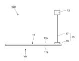
図1は本発明に係るスピーカー装置を模式的に示す正面図、図2及び図3は本発明に係るスピーカー装置を模式的に示す平面図である。
図1,図2,図3に示すように、スピーカー装置100は、光透過性を有する振動板11と、入力された電気信号に応じて振動を発生するエキサイタ(加振器)13と、振動板11とエキサイタ13とに接続され、エキサイタ13からの振動を振動板11に伝達する振動伝達部15とを備える。FIG. 1 is a front view schematically showing a speaker device according to the present invention, and FIGS. 2 and 3 are plan views schematically showing the speaker device according to the present invention.
As shown in FIGS. 1, 2, and 3, the
振動板11は、詳細な構成については後述するが、エキサイタ13が発生する振動によって励振されて音を発生し、図2の概ね矢印Va方向から見た場合に、振動板11を挟んだ奥側が透けて見える透光性を有することが好ましい。振動板11は、一枚の基板であってもよく、複数枚の基板を含む振動板構成体(詳細を後述)であってもよい。また、振動板11は平板であってもよく、曲面板であってもよい。更に、振動板11は透光性を有していなくてもよい。
Although the detailed configuration will be described later, the
振動板11は、縦波音速値が高い材料からなり、例えば、ガラス板、透光性セラミックス、サファイア等の単結晶等を用いることができる。
The
振動板11は、スピーカー装置100の使用目的に応じて、適宜な支持部材によって支持される。支持部材としては、例えば、振動板11の角部から板厚方向一方の側に延びる脚であってもよく、励振された振動を減衰させ難くしたクッション等の保持材であってもよい。
エキサイタ13は、図示は省略するが、外部機器と電気的に接続されたコイル部と、磁気回路部と、コイル部又は磁気回路部と連結された加振部とを含む。外部機器からの音の電気信号がコイル部へ入力されると、コイル部と磁気回路部との相互作用により、コイル部又は磁気回路部に振動が生じる。このコイル部又は磁気回路部の振動は加振部へ伝達されて、加振部から振動伝達部15に振動が伝達される。
Although not shown, the
振動伝達部15は、棒状のロッド部材17を含む。ロッド部材17は、金属、樹脂、ガラス繊維強化プラスチック、炭素繊維強化プラスチック等を用いることができる。ロッド部材17の軸方向の一端部はエキサイタ13の加振部に固定され、他端部は振動板11側に固定される。ロッド部材17の材料は、剛性が高い方が振動伝達の観点から好ましく、比弾性率(ヤング率を密度で除した値)で20mm2/s2以上が好ましく、30mm2/s2以上がより好ましく、40mm2/s2以上が更により好ましい。なお、ロッド部材17の長さは特に限定されないが、例えば、1cm以上、30cm以上、100cm以上、とすることができる。一方、ロッド長が長くなるとロッド部材の共振によるノイズが発生したり、ロッド部材による振動減衰効果により振動面から生じる音圧が減少するため、500cm以下が好ましく、200cm以下であることがより好ましい。
図示例の場合、ロッド部材17の他端部は、ロッド保持部材19を介して振動板11と接続される。ロッド保持部材19は、振動板11のVa方向における正面側の表面(第1主面11a)とは反対側の裏面(第2主面11b)に接合される。このロッド保持部材19は、例えばガラス製のブロックからなり、ロッド部材17に接着又は融着された後に、振動板11に接着材等によって接続される。またロッド保持部材19と振動板11との接続は、図3に示すようにロッド保持部材19を振動板11に挟み込んで接続することもできる。ロッド部材17とロッド保持部材19との接続は、ねじ等による締結であってもよい。
In the illustrated example, the other end of the
ロッド部材17とロッド保持部材19は、透光性の材料からなることが好ましい。その場合、振動板11に接続されても、振動板11の光透過性を損なうことがない。また、ロッド保持部材19は、ロッド部材17を直接、振動板11に接合する場合と比較して、振動板11との接合面積を増加させ、接合強度を高めることができる。ロッド保持部材19は、ガラスブロックの他、アクリルなどの樹脂、透光性セラミックス、サファイア等の単結晶材料を用いることもできる。
It is preferable that the
ロッド部材17(又はロッド保持部材19)と振動板11は、双方の接合面で屈折を生じにくくすることで、振動板11を外側から目視した際に、接合面が目立たなくなる。そのため、ロッド部材17(又はロッド保持部材19)と振動板11の屈折率は、できるだけ等しくすることが好ましく、双方の屈折率差は、0.2以下が好ましく、0.1以下がより好ましく、0.05以下が更により好ましい。上記の屈折率差にすることで、接合面が光透過性を有したまま視認されるようになり、美観を損なうことがない。
By making it difficult for the rod member 17 (or the rod holding member 19) and the
ロッド部材17の他端部は、振動板11が小型軽量である場合等、振動を印加する際に発生する応力が小さい場合には、ロッド保持部材19を用いず、振動板11に直接融着または接着してもよい。その場合、振動板11とロッド部材17との接合面積が小さくなり、接合面が目立ちにくくなる。
The other end of the
一方、振動板11が大型である場合等、ロッド保持部材19に大きな応力が負荷される場合には、金属等の非透光性のロッド保持部材19を用いてもよい。この場合、振動板11の光透過性をできるだけ損ねないよう、ロッド保持部材19と振動板11との接合面の面積を小さくする。接合面の面積は、振動板11の主面(第1主面11a、第2主面11b)の面積の1/100以下であることが好ましく、1/200以下であることがより好ましく、1/500以下であることが更により好ましい。一方、ロッド保持部材19と振動板11との接合強度を確保するため、上記接合面の面積は、1/10000以上であることが好ましい。
On the other hand, when a large stress is applied to the
ロッド部材17又はロッド保持部材19は、エキサイタ13の加振部から伝達される振動の振動方向と、振動板11の主面の法線とが略一致するように振動板11と接合することが好ましい。ロッド部材17の軸方向と、振動板11のロッド取り付け位置における法線方向とのなす角は、±60°であることが好ましく、±30°であることがより好ましく、±10°であることが更により好ましい。ロッド部材17の振動方向と振動板11の法線とのなす角が小さいほど、効率よく振動板11に振動を伝達でき、音圧レベルを大きくできる。
The
図1、図2に示すようにロッド部材17又はロッド保持部材19は、矩形状の振動板11の正面視で角部に接続されているが、これに限らない。振動板11との接続位置は、矩形辺に沿った任意の位置であってもよく、振動板11のデザイン性が損なわれない範囲で、主面上の任意の位置であってよい。また、振動板11に固定される他の部材にロッド部材17又はロッド保持部材19を接続してもよい。
As shown in FIGS. 1 and 2, the
振動伝達部15は、ここでは棒状のロッド部材17を用いているが、これに限らず、少なくとも1つの湾曲部や屈曲部を有する曲線部が形成されたものであってもよい。その場合、エキサイタ13を振動板11の背面以外の側方等にも設置でき、エキサイタ13の配置自由度が高められる。
The
さらに、振動伝達部15は、振動板11とエキサイタ13の加振部との間に張られたワイヤ部材であってもよい。ワイヤ部材は、振動板11に張力が負荷された状態で接続されることで、エキサイタ13からの振動を振動板11に伝達できる。これによれば、振動板11を天井や壁面からワイヤ部材で吊す等、振動板11の設置自由度を高められる。
Furthermore, the
上記した振動伝達部15は、1枚の振動板11に対して1つの振動伝達部を接続する構成に限らず、複数の振動伝達部を接続した構成にしてもよい。更にその場合、複数の振動伝達部にそれぞれ個別にエキサイタが接続されていてもよい。
The
ここで、振動板11について、更に詳細に説明する。
振動板11は、振動減衰特性を表す損失係数が低いと、共振振動が生じる。特に振動伝達部15を介して間接駆動される場合、振動板11が自由に振動しやすく、エキサイタ13の強制振動によって共振を抑制しにくい。そのため、スピーカー装置100に用いる振動板11としては、損失係数の大きい、すなわち、振動減衰能が大きいものを用いる必要がある。振動板11の損失係数は、25℃において好ましくは1×10⁻²以上、より好ましくは2×10⁻²以上、更により好ましくは5×10⁻²以上である。ただし、損失係数が大きすぎると減衰過多となり振動板としての効率が低下することから、損失係数は好ましくは5以下、より好ましくは2以下であり、1以下が更により好ましい。Here, the
When the
損失係数とは、半値幅法により算出したものを用いる。材料の共振周波数f、振幅hであるピーク値から-3dB下がった点(すなわち、最大振幅-3[dB]における点)の周波数幅をWとしたときに、{W/f}で表される値を損失係数と定義する。共振を抑えるには、損失係数を大きくすればよく、すなわち、振幅hに対し相対的に周波数幅Wは大きくなり、ピークがブロードとなることを意味する。 A loss factor calculated by the half width method is used. A loss factor is defined as a value represented by {W/f}, where W is the frequency width at a point -3 dB lower than the peak value of the material's resonance frequency f and amplitude h (that is, the point at the maximum amplitude -3 [dB]). Resonance can be suppressed by increasing the loss factor, which means that the frequency width W is increased relative to the amplitude h, and the peak is broadened.
損失係数は材料等の固有の値であり、例えばガラス板単体の場合にはその組成や相対密度等によって異なる。なお、損失係数は共振法などの動的弾性率試験法により測定することができる。 The loss factor is a value specific to the material, etc. For example, in the case of a single glass plate, it varies depending on its composition, relative density, and the like. The loss factor can be measured by a dynamic elastic modulus test method such as a resonance method.
振動板11が振動伝達部15を介して駆動される場合、音波振動によく追従する振動板が求められる。この追従性は縦波音速値で表され、縦波音速値が速いほど追従性が高くなる。一枚の振動板11の板厚方向の縦波音速値、または、振動板11が複数の基板を含む場合は少なくとも1枚の基板の板厚方向の縦波音速値は、好ましくは3000m/s以上、より好ましくは3500m/s以上、更により好ましくは4000m/s以上である。
When the
縦波音速値とは、物体中を縦波が伝搬する速度をいう。縦波音速値及びヤング率は、日本工業規格(JIS-R1602-1995)に記載された超音波パルス法により測定できる。 Longitudinal sound velocity value refers to the velocity at which longitudinal waves propagate through an object. The longitudinal wave sound velocity value and Young's modulus can be measured by the ultrasonic pulse method described in Japanese Industrial Standards (JIS-R1602-1995).
ここで、振動板11は、高い損失係数及び高い縦波音速値を得るための具体的な構成として、2枚以上の基板を含み、基板のうち少なくとも一対の基板の間に所定の中間層を含むことが好ましい。
Here, as a specific configuration for obtaining a high loss factor and a high longitudinal wave sound velocity value, the
<振動板構成体>
図4は振動板11の他の例として、複数の基板、及び基板間に配置される中間層を含む振動板構成体11Aの層構成を示す概略断面図である。
振動板構成体11Aは、一対の基板21,23と、基板21と基板23との間に配置された中間層25とを有する。なお、基板21,23は、透光性を有することが好ましいが、透光性を有さない基板であってもよい。<Diaphragm structure>
FIG. 4 is a schematic cross-sectional view showing a layer structure of a
The
基板21,23の材料のうち、少なくとも1枚の基板は、縦波音速値の高い透光性材料、例えば、ガラス板、透光性セラミックス、サファイア等の単結晶を用いることができる。 Of the materials of the substrates 21 and 23, at least one substrate can be made of a translucent material with a high longitudinal wave sound velocity value, such as a glass plate, translucent ceramics, or a single crystal such as sapphire.
(中間層)
中間層25には有機材料が用いられ、例えば樹脂シートやブチラール樹脂(PVB)等の粘着層が使用できる。また、中間層25は、例えばシリコーン等の液体層であってもよい。中間層25がシート状の部材であれば、製造工程における取り扱い性が容易となり、製造工程を簡素化できる。中間層25が液体層である場合は、高い損失係数を実現することができる。中でも、液体層の粘性や表面張力を好適な範囲にすることで、より損失係数を高くすることができる。これは、一対の基板21,23が粘着層を介して接合された場合とは異なり、一対の基板21,23が固着せず、各々の基板としての振動特性を持ち続けることに起因するものと考えられる。(middle layer)
An organic material is used for the intermediate layer 25, and for example, an adhesive layer such as a resin sheet or butyral resin (PVB) can be used. Alternatively, the intermediate layer 25 may be a liquid layer such as silicone. If the intermediate layer 25 is a sheet-like member, it becomes easy to handle in the manufacturing process, and the manufacturing process can be simplified. A high loss factor can be achieved if the intermediate layer 25 is a liquid layer. Above all, the loss factor can be further increased by setting the viscosity and surface tension of the liquid layer within suitable ranges. This is thought to be due to the fact that the pair of substrates 21 and 23 do not adhere to each other, unlike the case where the pair of substrates 21 and 23 are bonded via an adhesive layer, and each substrate maintains its vibration characteristics.
中間層25の厚さは、薄いほど高剛性の維持及び振動伝達の点から好ましい。具体的には、中間層25の厚さは、100μm以下が好ましく、50μm以下がより好ましく、10μm以下が更に好ましい。中間層25の厚さの下限は、生産性及び耐久性の点から0.01μm以上が好ましい。 The thickness of the intermediate layer 25 is preferably as thin as possible in terms of maintaining high rigidity and transmitting vibration. Specifically, the thickness of the intermediate layer 25 is preferably 100 μm or less, more preferably 50 μm or less, and even more preferably 10 μm or less. The lower limit of the thickness of the intermediate layer 25 is preferably 0.01 μm or more in terms of productivity and durability.
中間層25の厚さが、基板21,23の板厚以上となると、縦波音速値の低下が顕著となるため、中間層25の厚さの上限は、基板21,23の板厚と同厚以下であることが好ましく、板厚の50%以下であることがより好ましく、板厚の10%以下であることが更により好ましい。 When the thickness of the intermediate layer 25 is equal to or greater than the thickness of the substrates 21 and 23, the longitudinal wave speed of sound decreases significantly. Therefore, the upper limit of the thickness of the intermediate layer 25 is preferably equal to or less than the thickness of the substrates 21 and 23, more preferably 50% or less of the thickness, and even more preferably 10% or less of the thickness.
中間層25が液体層である場合、液体層は25℃における粘性係数が1×10⁻⁴~1×10³Pa・sであり、かつ、25℃における表面張力が15~80mN/mであることが好ましい。粘性が低すぎると振動を伝達しにくくなり、高すぎると液体層の両側に位置する一対の基板21,23同士が固着して一枚の基板としての振動挙動を示すようになることから、共振による振動が減衰されにくくなる。また、表面張力が低すぎると基板間の密着力が低下し、振動を伝達しにくくなる。表面張力が高すぎると、液体層の両側に位置する一対の基板同士が固着しやすくなり、一枚の基板としての振動挙動を示すようになることから、共振による振動が減衰されにくくなる。When the intermediate layer 25 is a liquid layer, the liquid layer preferably has a viscosity coefficient of 1×10 -4 to 1×10 3 Pa·s at 25°C and a surface tension of 15 to 80 mN/m at 25°C. If the viscosity is too low, it becomes difficult to transmit vibration, and if the viscosity is too high, the pair of substrates 21 and 23 located on both sides of the liquid layer adhere to each other and exhibit vibration behavior as a single substrate, making it difficult to attenuate vibration due to resonance. On the other hand, if the surface tension is too low, the adhesion between the substrates will decrease, making it difficult to transmit vibrations. If the surface tension is too high, the pair of substrates positioned on both sides of the liquid layer will tend to adhere to each other, exhibiting vibration behavior as a single substrate, making it difficult to attenuate vibration due to resonance.
液体層の25℃における粘性係数は1×10⁻³Pa・s以上がより好ましく、1×10⁻²Pa・s以上が更に好ましい。また、1×10²Pa・s以下がより好ましく、1×10Pa・s以下が更に好ましい。
液体層の25℃における表面張力は20mN/m以上がより好ましく、30mN/m以上が更に好ましい。The viscosity coefficient of the liquid layer at 25° C. is more preferably 1×10 −3 Pa·s or more, further preferably 1×10 −2 Pa·s or more. Moreover, 1*10 <2> Pa*s or less is more preferable, and 1*10 Pa*s or less is still more preferable.
The surface tension of the liquid layer at 25° C. is more preferably 20 mN/m or more, still more preferably 30 mN/m or more.
液体層の粘性係数は回転粘度計などにより測定することができる。
液体層の表面張力はリング法などにより測定することができる。The viscosity coefficient of the liquid layer can be measured with a rotational viscometer or the like.
The surface tension of the liquid layer can be measured by a ring method or the like.
液体層は、蒸気圧が高すぎると液体層が蒸発して振動板構成体としての機能を果たさなくなるおそれがある。そのため、液体層は、25℃、1atmにおける蒸気圧が1×10⁴Pa以下が好ましく、5×10³Pa以下がより好ましく、1×10³Pa以下が更に好ましい。また、蒸気圧が高い場合には、液体層が蒸発しないようにシール等を施してもよいが、このとき、シール材により振動板構成体の振動を妨げないようにする必要がある。If the vapor pressure of the liquid layer is too high, the liquid layer may evaporate and fail to function as the diaphragm structure. Therefore, the vapor pressure of the liquid layer at 25° C. and 1 atm is preferably 1×10 4 Pa or less, more preferably 5×10 3 Pa or less, even more preferably 1×10 3 Pa or less. If the vapor pressure is high, a seal or the like may be applied to prevent the liquid layer from evaporating.
液体層は化学的に安定であり、液体層に接する基板が反応しないことが好ましい。化学的に安定とは、例えば光照射により変質(劣化)が少ないものであったりして、少なくとも-20~70℃の温度領域で凝固、気化、分解、変色、基板との化学反応等が生じないものを意味する。 Preferably, the liquid layer is chemically stable and the substrate in contact with the liquid layer does not react. Chemically stable means, for example, one that is less altered (deteriorated) by light irradiation, and does not cause solidification, vaporization, decomposition, discoloration, chemical reaction with the substrate, etc. at least in the temperature range of -20 to 70 ° C.
液体層の成分としては、具体的には、水、オイル、有機溶剤、液状ポリマー、イオン性液体及びそれらの混合物等が挙げられる。
より具体的には、プロピレングリコール、ジプロピレングリコール、トリプロピレングリコール、ストレートシリコーンオイル(ジメチルシリコーンオイル、メチルフェニルシリコーンオイル、メチルハイドロジェンシリコーンオイル)、変性シリコーンオイル、アクリル酸系ポリマー、液状ポリブタジエン、グリセリンペースト、フッ素系溶剤、フッ素系樹脂、アセトン、エタノール、キシレン、トルエン、水、鉱物油、及びそれらの混合物、等が挙げられる。中でも、プロピレングリコール、ジメチルシリコーンオイル、メチルフェニルシリコーンオイル、メチルハイドロジェンシリコーンオイル及び変性シリコーンオイルからなる群より選ばれる少なくとも1種を含むことが好ましく、プロピレングリコール又はシリコーンオイルを主成分とすることがより好ましい。Specific examples of components of the liquid layer include water, oil, organic solvents, liquid polymers, ionic liquids and mixtures thereof.
More specific examples include propylene glycol, dipropylene glycol, tripropylene glycol, straight silicone oil (dimethyl silicone oil, methylphenyl silicone oil, methylhydrogen silicone oil), modified silicone oil, acrylic acid-based polymer, liquid polybutadiene, glycerin paste, fluorine-based solvents, fluorine-based resins, acetone, ethanol, xylene, toluene, water, mineral oils, and mixtures thereof. Among them, it preferably contains at least one selected from the group consisting of propylene glycol, dimethylsilicone oil, methylphenylsilicone oil, methylhydrogensilicone oil and modified silicone oil, and more preferably contains propylene glycol or silicone oil as the main component.
上記の他に、粉体を分散させたスラリーを液体層として使用することもできる。損失係数の向上といった観点からは、液体層は均一な流体であることが好ましいが、振動板構成体11Aに着色や蛍光等といった意匠性や機能性を付与する場合には、上記したスラリーは有効である。
液体層における粉体の含有量は0~10体積%が好ましく、0~5体積%がより好ましい。
粉体の粒径は沈降を防ぐ観点から10nm~1μmが好ましく、0.5μm以下がより好ましい。In addition to the above, a slurry in which powder is dispersed can also be used as the liquid layer. From the viewpoint of improving the loss factor, it is preferable that the liquid layer is a uniform fluid. However, the slurry described above is effective when imparting design and functionality such as coloring and fluorescence to the
The powder content in the liquid layer is preferably 0 to 10% by volume, more preferably 0 to 5% by volume.
The particle size of the powder is preferably 10 nm to 1 μm, more preferably 0.5 μm or less, from the viewpoint of preventing sedimentation.
また、意匠性、機能性付与の観点から、液体層が蛍光材料を含んでもよい。蛍光材料を粉体として分散させたスラリー状の液体層でも、蛍光材料を液体として混合させた均一な液体層でもよい。これにより、振動板構成体11Aに光の吸収及び発光といった光学的機能を付与することができる。
Moreover, from the viewpoint of designability and functionality, the liquid layer may contain a fluorescent material. A slurry-like liquid layer in which the fluorescent material is dispersed as powder, or a uniform liquid layer in which the fluorescent material is mixed as a liquid may be used. This makes it possible to impart optical functions such as light absorption and light emission to the
(基板)
本発明に係るスピーカー装置100に用いる振動板構成体11Aは、中間層25を厚さ方向の両側から挟むように、少なくとも一対の基板21,23が設けられる。一方の基板21が共振した場合に、中間層25が液体層であると他方の基板23が共振しない、又は、他方の基板23における共振の揺れを減衰できる。このため、振動板構成体11Aは、基板単独の場合と比べて損失係数を高くすることができる。(substrate)
A
一対の基板21,23のうち、一方の基板と他方の基板との共振周波数のピークトップの値は異なることが好ましく、共振周波数の範囲が重なっていないものがより好ましい。ただし、基板21,23の共振周波数の範囲が重複していたり、ピークトップの値が同じであっても、中間層、好ましくは液体層の存在によって、一方の基板が共振しても、他方の基板の振動が同期しないことで、ある程度共振が相殺される。そのため、基板単独の場合に比べて高い損失係数を得ることができる。 Of the pair of substrates 21 and 23, it is preferable that the values of the peak tops of the resonance frequencies of one substrate and the other substrate are different, and it is more preferable that the resonance frequency ranges do not overlap. However, even if the resonance frequency ranges of the substrates 21 and 23 overlap or the peak top values are the same, the existence of the intermediate layer, preferably the liquid layer, cancels out the resonance to some extent because even if one substrate resonates, the vibration of the other substrate does not synchronize. Therefore, it is possible to obtain a higher loss factor than in the case of using only the substrate.
すなわち、一方の基板の共振周波数(ピークトップ)をQa、共振振幅の半値幅をwa、他方の基板の共振周波数(ピークトップ)をQb、共振振幅の半値幅をwbとしたときに、下記[式1]の関係を満たすことが好ましい。
(wa+wb)/4<|Qa-Qb|・・・[式1]
上記[式1]における左辺の値が大きくなるほど一方の基板と他方の基板との共振周波数の差異(|Qa-Qb|)が大きくなり、高い損失係数が得られるようになることから好ましい。That is, when the resonance frequency (peak top) of one substrate is Qa, the half width of the resonance amplitude is wa, the resonance frequency (peak top) of the other substrate is Qb, and the half width of the resonance amplitude is wb, it is preferable to satisfy the following [Equation 1].
(wa+wb)/4<|Qa-Qb| ... [Formula 1]
The larger the value of the left side of [Equation 1], the larger the difference in resonance frequency (|Qa−Qb|) between one substrate and the other substrate, which is preferable because a high loss factor can be obtained.
そのため、下記[式2]を満たすことがより好ましく、下記[式3]を満たすことがより好ましい。
(wa+wb)/2<|Qa-Qb|・・・[式2]
(wa+wb)/1<|Qa-Qb|・・・[式3]
なお、基板の共振周波数(ピークトップ)及び共振振幅の半値幅は、振動板構成体における損失係数と同様の方法で測定することができる。Therefore, it is more preferable to satisfy the following [Formula 2], and it is more preferable to satisfy the following [Formula 3].
(wa+wb)/2<|Qa-Qb| ... [Formula 2]
(wa+wb)/1<|Qa-Qb| ... [Formula 3]
The resonance frequency (peak top) of the substrate and the half width of the resonance amplitude can be measured in the same manner as the loss factor of the diaphragm structure.
一対の基板は、質量差が小さいほど好ましく、質量差がないことがより好ましい。基板同士の質量差がある場合、軽い方の基板の共振は重い方の基板で抑制することはできるが、重い方の基板の共振を軽い方の基板で抑制することは困難である。すなわち、質量比に偏りがあると、慣性力の差異により原理的に共振による振動を互いに打ち消せなくなるためである。 A pair of substrates preferably have a smaller mass difference, and more preferably have no mass difference. When there is a mass difference between the substrates, the resonance of the lighter substrate can be suppressed by the heavier substrate, but it is difficult to suppress the resonance of the heavier substrate by the lighter substrate. That is, if there is a bias in the mass ratio, the difference in inertial force makes it impossible in principle to cancel out the vibrations due to resonance.
ここで、(基板A/基板B)で表される基板A及び基板Bの質量比は、0.1~10.0(1/10~10/1)が好ましく、0.8~1.25(8/10~10/8)が好ましく、0.9~1.1(9/10~10/9)がより好ましく、1.0(10/10)が更に好ましい。 Here, the mass ratio of the substrate A and the substrate B represented by (substrate A/substrate B) is preferably 0.1 to 10.0 (1/10 to 10/1), preferably 0.8 to 1.25 (8/10 to 10/8), more preferably 0.9 to 1.1 (9/10 to 10/9), and even more preferably 1.0 (10/10).
基板の厚さは、いずれも薄いほど、基板同士が中間層、好ましくは液体層を介して密着しやすく、また、基板を少ないエネルギーで振動させることができる。そのため、スピーカー等の振動板用途の場合には、基板の厚さは薄いほど好ましい。具体的には、基板の板厚は、それぞれ15mm以下が好ましく、10mm以下がより好ましく、5mm以下が更に好ましく、3mm以下が更により好ましく、1.5mm以下が特に好ましく、0.8mm以下が特により好ましい。一方、薄すぎると、基板の表面欠陥の影響が顕著になりやすく、割れが生じやすくなったり、強化処理しにくくなったりする。そのため、基板の厚さは0.01mm以上が好ましく、0.05mm以上がより好ましい。 The thinner the substrates, the easier it is for the substrates to come into close contact with each other via an intermediate layer, preferably a liquid layer, and the less energy the substrates can be vibrated. Therefore, in the case of diaphragm applications such as speakers, the thinner the substrate, the better. Specifically, the thickness of each substrate is preferably 15 mm or less, more preferably 10 mm or less, still more preferably 5 mm or less, even more preferably 3 mm or less, particularly preferably 1.5 mm or less, and particularly preferably 0.8 mm or less. On the other hand, if it is too thin, the effect of surface defects on the substrate tends to be noticeable, cracking tends to occur, and strengthening treatment becomes difficult. Therefore, the thickness of the substrate is preferably 0.01 mm or more, more preferably 0.05 mm or more.
また、共振現象に起因する異音の発生を抑制した建築・車両用開口部材用途においては、基板の板厚は、それぞれ0.5~15mmが好ましく、0.8~10mmがより好ましく、1.0~8mmが更に好ましい。 Further, in applications for opening members for construction and vehicles that suppress the generation of noise caused by resonance, the plate thickness of the substrate is preferably 0.5 to 15 mm, more preferably 0.8 to 10 mm, and even more preferably 1.0 to 8 mm.
一対の基板の少なくともいずれか一方は、損失係数が大きい方が、振動板構成体としての振動減衰も大きくなり、振動板用途として好ましい。具体的には、基板の25℃における損失係数は1×10⁻⁴以上が好ましく、3×10⁻⁴以上がより好ましく、5×10⁻⁴以上が更に好ましい。また、一対の基板の両方が、上記損失係数を有することがより好ましい。
なお、基板の損失係数は、前述した振動板11における損失係数と同様の方法で測定することができる。When at least one of the pair of substrates has a large loss factor, the vibration damping of the diaphragm structure is increased, which is preferable for the diaphragm application. Specifically, the loss factor of the substrate at 25° C. is preferably 1×10 −4 or more, more preferably 3×10 −4 or more, and even more preferably 5×10 −4 or more. Moreover, it is more preferable that both of the pair of substrates have the above loss factor.
The loss factor of the substrate can be measured by the same method as the loss factor of the
基板の少なくともいずれか一方は、板厚方向の縦波音速値が高い方が高周波領域の音の再現性が向上することから、振動板用途として好ましい。具体的には、基板の縦波音速値が4.0×10³m/s以上が好ましく、5.0×103m/s以上がより好ましく、6.0×103m/s以上が更に好ましい。上限は特に限定されないが、基板の生産性や原料コストの観点から7.0×103m/s以下が好ましい。また、一対の基板の両方が、上記音速値を満たすことがより好ましい。
なお、基板の音速値は、前述した振動板11における縦波音速値と同様の方法で測定することができる。At least one of the substrates is preferable for use as a diaphragm because the reproducibility of sound in a high frequency region is improved when the longitudinal wave sound velocity value in the plate thickness direction is high. Specifically, the longitudinal wave sound velocity value of the substrate is preferably 4.0×10 3 m/s or more, more preferably 5.0×10 3 m/s or more, and still more preferably 6.0×10 3 m/s or more. Although the upper limit is not particularly limited, it is preferably 7.0×10 3 m/s or less from the viewpoint of substrate productivity and raw material costs. Moreover, it is more preferable that both of the pair of substrates satisfy the above sound velocity value.
The acoustic velocity value of the substrate can be measured by the same method as the longitudinal wave acoustic velocity value in the
基板がガラス板である場合、そのガラス板の組成は特に限定されないが、例えば下記範囲であることが好ましい。
SiO2:40~80質量%、Al2O3:0~35質量%、B2O3:0~15質量%、MgO:0~20質量%、CaO:0~20質量%、SrO:0~20質量%、BaO:0~20質量%、Li2O:0~20質量%、Na2O:0~25質量%、K2O:0~20質量%、TiO2:0~10質量%、かつ、ZrO2:0~10質量%。但し上記組成がガラス全体の95質量%以上を占める。When the substrate is a glass plate, the composition of the glass plate is not particularly limited, but is preferably within the following range, for example.
SiO 2 : 40 to 80% by mass, Al 2 O 3 : 0 to 35% by mass, B 2 O 3 : 0 to 15% by mass, MgO: 0 to 20% by mass, CaO: 0 to 20% by mass, SrO: 0 to 20% by mass, BaO: 0 to 20% by mass, Li 2 O: 0 to 20% by mass, Na 2 O : 0 to 25% by mass, K 2 O: 0 to 20% by mass, TiO 2 : 0 to 10% by mass, and ZrO 2 : 0 to 10% by mass. However, the above composition accounts for 95% by mass or more of the entire glass.
ガラス板の組成は、より好ましくは下記範囲である。
SiO2:55~75質量%、Al2O3:0~25質量%、B2O3:0~12質量%、MgO:0~20質量%、CaO:0~20質量%、SrO:0~20質量%、BaO:0~20質量%、Li2O:0~20質量%、Na2O:0~25質量%、K2O:0~15質量%、TiO2:0~5質量%、かつ、ZrO2:0~5質量%。但し上記組成がガラス全体の95質量%以上を占める。The composition of the glass plate is more preferably within the following range.
SiO 2 : 55 to 75% by mass, Al 2 O 3 : 0 to 25% by mass, B 2 O 3 : 0 to 12% by mass, MgO: 0 to 20% by mass, CaO: 0 to 20% by mass, SrO: 0 to 20% by mass, BaO: 0 to 20% by mass, Li 2 O: 0 to 20% by mass, Na 2 O: 0 to 25% by mass, K 2 O: 0 to 15% by mass, TiO 2 : 0 to 5% by mass, and ZrO 2 : 0 to 5% by mass. However, the above composition accounts for 95% by mass or more of the entire glass.
基板の比重はいずれも小さいほど、少ないエネルギーでガラス板を振動させることができる。具体的には、基板がガラス板である場合、ガラス板の比重はそれぞれ2.8以下が好ましく、2.6以下がより好ましく、2.5以下が更により好ましい。下限は特に限定されないが、2.2以上であることが好ましい。
基板のヤング率を密度で除した値である比弾性率は、いずれも大きいほど、基板の剛性を高められる。具体的には、基板の比弾性率が、それぞれ2.5×10⁷m2/s2以上が好ましく、2.8×107m2/s2以上がより好ましく、3.0×107m2/s2以上が更により好ましい。上限は特に限定されないが、4.0×107m2/s2以下であることが好ましい。The smaller the specific gravity of the substrate, the less energy the glass plate can vibrate. Specifically, when the substrate is a glass plate, the specific gravity of each glass plate is preferably 2.8 or less, more preferably 2.6 or less, and even more preferably 2.5 or less. Although the lower limit is not particularly limited, it is preferably 2.2 or more.
The higher the specific elastic modulus, which is the value obtained by dividing the Young's modulus of the substrate by the density, the higher the rigidity of the substrate. Specifically, the specific elastic modulus of the substrate is preferably 2.5×10 7 m 2 /s 2 or more, more preferably 2.8×10 7 m 2 /s 2 or more, and even more preferably 3.0×10 7 m 2 /s 2 or more. Although the upper limit is not particularly limited, it is preferably 4.0×10 7 m 2 /s 2 or less.
(振動板構成体の特性及び構成例)
振動板構成体11Aにおける損失係数は、大きいほど振動減衰が大きくなることから好ましい。スピーカー装置100に用いる振動板構成体11Aの25℃における損失係数は、1×10⁻²以上であり、好ましくは2×10⁻²以上、より好ましくは4×10⁻²以上、特に好ましくは5×10⁻²以上である。(Characteristics and Configuration Example of Diaphragm Constituent)
The larger the loss factor in the
振動板構成体11Aの板厚方向の縦波音速値は、音速が速いほど振動板とした際に高周波音の再現性が向上することから、好ましくは4.0×10³m/s以上であり、より好ましくは5.0×103m/s以上、更により好ましくは6.0×103m/s以上である。上限は特に限定されないが、7.0×103m/s以下が好ましい。The longitudinal wave sound velocity value in the plate thickness direction of the
振動板構成体11Aの直線透過率が高いと、透光性の部材としての適用が可能となる。そのため、振動板構成体11Aは、日本工業規格(JIS R3106-1998)に準拠して求められた可視光透過率が10%以上であることが好ましく、30%以上がより好ましく、50%以上が更に好ましく、70%以上、さらには90%以上がよりさらに好ましい。
If the linear transmittance of the
振動板構成体11Aの透過率を高めるために、屈折率を整合させることも有用である。すなわち、振動板構成体11Aを構成する基板21,23と中間層25の屈折率は近いほど、界面における反射及び干渉が防止されることから好ましい。中でも中間層25の屈折率と中間層25に接する一対の基板21,23の屈折率との差は、いずれも0.2以下が好ましく、0.1以下がより好ましく、0.01以下であることが更により好ましい。
It is also useful to match the refractive index to increase the transmittance of the
振動板構成体11Aを構成する基板21,23の少なくとも1枚及び中間層25の少なくともいずれか一方に着色することも可能である。これは、振動板構成体11Aに更に意匠性を持たせたい場合や、IRカット、UVカット、プライバシーガラス等の機能性を持たせたい場合に有用である。
It is also possible to color at least one of the substrates 21 and 23 and at least one of the intermediate layer 25 that constitute the
振動板構成体11Aを構成する基板21,23は2枚以上であればよいが、3枚以上の基板を用いてもよい。いずれの場合でも、各基板として、すべて異なる組成の基板を用いてもよく、すべて同じ組成の基板を用いてもよく、同じ組成の基板と異なる組成の基板とを組み合わせて用いてもよい。中でも、異なる組成からなる2種類以上の基板を用いることが振動減衰性の点から好ましく用いられる。
基板の質量や厚さについても同様に、すべて異なっても、すべて同一でも、一部が異なっていてもよい。中でも、構成する基板の質量がすべて同一であることが振動減衰性の点から好ましく用いられる。The number of substrates 21 and 23 constituting the
Similarly, the mass and thickness of the substrates may be all different, all the same, or partially different. Above all, it is preferable from the standpoint of vibration damping that all the constituent substrates have the same mass.
振動板構成体11Aを構成する基板21,23の少なくとも1枚に、物理強化ガラス板や化学強化ガラス板を用いることもできる。これは、振動板構成体の破壊を防ぐのに有用である。振動板構成体の強度を高めたい場合には、振動板構成体11Aの最表面に位置する基板を物理強化ガラス板又は化学強化ガラス板とすることが好ましく、構成するガラス板のすべてが物理強化ガラス板又は化学強化ガラス板であることがより好ましい。
A physically strengthened glass plate or a chemically strengthened glass plate can also be used for at least one of the substrates 21 and 23 constituting the
ガラス板として、結晶化ガラスや分相ガラスを用いることも、縦波音速値や強度を高める点から有用である。特に、振動板構成体の強度を高めたい場合には、振動板構成体の最表面に位置するガラス板を結晶化ガラス又は分相ガラスとすることが好ましい。 The use of crystallized glass or phase-separated glass as the glass plate is also useful from the viewpoint of increasing the longitudinal wave sound velocity value and strength. In particular, when it is desired to increase the strength of the diaphragm assembly, it is preferable to use crystallized glass or phase-separated glass for the glass plate located on the outermost surface of the diaphragm assembly.
振動板構成体11Aの少なくとも一方の最表面に本発明の効果を損なわない範囲でコーティング層やフィルム層を形成してもよい。コーティング層の施工やフィルム層の貼付は、例えば傷付き防止等に好適である。
コーティング層やフィルム層の厚さは、基板の板厚の1/5以下であることが好ましい。コーティングやフィルムには従来公知の物を用いることができるが、コーティングとしては例えば撥水コーティング、親水コーティング、滑水コーティング、撥油コーティング、光反射防止コーティング、遮熱コーティング、等が挙げられる。また、フィルムとしては例えばガラス飛散防止フィルム、カラーフィルム、UVカットフィルム、IRカットフィルム、遮熱フィルム、電磁波シールドフィルム、プロジェクター用スクリーンフィルム等が挙げられる。A coating layer or a film layer may be formed on at least one of the outermost surfaces of the
The thickness of the coating layer or film layer is preferably 1/5 or less of the thickness of the substrate. Conventionally known coatings and films can be used, and examples of coatings include water-repellent coatings, hydrophilic coatings, water-sliding coatings, oil-repellent coatings, light-reflecting coatings, and heat-shielding coatings. Examples of films include anti-glass scattering films, color films, UV cut films, IR cut films, heat shielding films, electromagnetic wave shielding films, screen films for projectors, and the like.
振動板構成体11Aの形状は、用途によって適宜設計することができ、平面板状であっても曲面形状でもよい。
例えば、低周波数帯域の出力音圧レベルを上げるため、振動板構成体11Aにエンクロージャー又はバッフル板を付与した構造とすることもできる。エンクロージャー又はバッフル板の材質は特に限定されないが、上記した振動板11を用いることが好ましい。The shape of the
For example, in order to increase the output sound pressure level in the low frequency band, the
振動板構成体11Aの少なくとも一方の最表面に本発明の効果を損なわない範囲で、フレームを設けてもよい。フレームは、振動板構成体11Aの剛性を向上させたい場合、あるいは曲面形状を保持したい場合等に有用である。フレームの材質としては従来公知の物を用いることができるが、例えばAl2O3、SiC、Si3N4、AlN、ムライト、ジルコニア、イットリア、YAG等のセラミックス及び単結晶材料、鋼、アルミニウム、チタン、マグネシウム、炭化タングステン等の金属及び合金材料、FRP等の複合材料、アクリル、ポリカーボネート等の樹脂材料、ガラス材料、木材等を用いることができる。A frame may be provided on at least one of the outermost surfaces of the
用いるフレームの重量は、ガラス板の重量の20%以下であることが好ましく、10%以下であることがより好ましい。
なお、振動板構成体11Aとフレームとの間にはシール材を配置することで、液体層のフレームからの漏れを防止できる。The weight of the frame used is preferably 20% or less, more preferably 10% or less, of the weight of the glass plate.
By placing a sealing material between the
振動板構成体11Aの外周端部の少なくとも一部を、振動板構成体11Aの振動を妨げない部材でシールしてもよい。このシール材としては、伸縮性の高いゴム、樹脂、ゲル等を用いることができる。
At least part of the outer peripheral edge of the
シール材用の樹脂に関しては、アクリル系、シアノアクリレート系、エポキシ系、シリコーン系、ウレタン系、フェノール系等を用いることができる。硬化方法としては一液型、二液混合型、加熱硬化、紫外線硬化、可視光硬化等が挙げられる。 Acrylic, cyanoacrylate, epoxy, silicone, urethane, phenol, and the like can be used as resins for sealing materials. Curing methods include one-liquid type, two-liquid mixed type, heat curing, ultraviolet curing, visible light curing, and the like.
熱可塑性樹脂(ホットメルトボンド)を用いることもできる。一例として、エチレン酢酸ビニル系、ポリオレフィン系、ポリアミド系、合成ゴム系、アクリル系、ポリウレタン系が挙げられる。 A thermoplastic resin (hot melt bond) can also be used. Examples include ethylene vinyl acetate, polyolefin, polyamide, synthetic rubber, acrylic, and polyurethane.
ゴムに関しては、例えば天然ゴム、合成天然ゴム、ブタジエンゴム、スチレン・ブタジエンゴム、ブチルゴム、ニトリルゴム、エチレン・プロピレンゴム、クロロプレンゴム、アクリルゴム、クロロスルホン化ポリエチレンゴム(ハイパロン)、ウレタンゴム、シリコーンゴム、フッ素ゴム、エチレン・酢酸ビニルゴム、エピクロルヒドリンゴム、多硫化ゴム(チオコール)、水素化ニトリルゴムを用いることができる。 Examples of rubbers that can be used include natural rubber, synthetic natural rubber, butadiene rubber, styrene-butadiene rubber, butyl rubber, nitrile rubber, ethylene-propylene rubber, chloroprene rubber, acrylic rubber, chlorosulfonated polyethylene rubber (Hypalon), urethane rubber, silicone rubber, fluororubber, ethylene-vinyl acetate rubber, epichlorohydrin rubber, polysulfide rubber (thiocol), and hydrogenated nitrile rubber.
シール材の厚さは、薄すぎると十分な強度が確保されず、厚すぎると振動の支障となる。ゆえにシール材の厚さは10μm以上かつガラス構成体の合計厚さの5倍以下であることが好ましく、50μm以上かつガラス構成体の合計厚さより薄いことがより好ましい。 If the thickness of the sealing material is too thin, sufficient strength cannot be ensured, and if it is too thick, vibration will be hindered. Therefore, the thickness of the sealing material is preferably 10 μm or more and 5 times or less than the total thickness of the glass structure, and more preferably 50 μm or more and less than the total thickness of the glass structure.
振動板構成体11Aの基板21,23と中間層25との界面における剥離防止等のために、向かい合う基板21,23の主面の少なくとも一部に、本発明の効果を損なわない範囲で上記のシール材を塗布することができる。この場合、シール材塗布部の面積は、振動の支障とならないように中間層25の面積の20%以下であることが好ましく、10%以下であることがより好ましく、5%以下であることが特に好ましい。
In order to prevent peeling at the interface between the substrates 21, 23 and the intermediate layer 25 of the
また、シール性能を向上するために、基板21,23のエッジ部分を適切な形状に加工することもできる。例えば、少なくとも一方の基板の端部をC面取り(基板の断面形状が台形形状)又はR面取り(基板の断面形状が略円弧状)することにより、シール材と基板との接触面積を増大させ、シール材と基板との接着強度が向上する。 Also, in order to improve the sealing performance, the edge portions of the substrates 21 and 23 can be processed into appropriate shapes. For example, by chamfering at least one end of the substrate (substrate has a trapezoidal cross-sectional shape) or R-chamfering (substrate has a substantially arcuate cross-sectional shape), the contact area between the sealing material and the substrate is increased, and the bonding strength between the sealing material and the substrate is improved.
<適用例> 以上説明したスピーカー装置100の振動板(振動板11,振動板構成体11A)は、主面の面積を広く採れることを活かし、例えば、振動板の視認方向(図2のVa方向)の奥側に、表示用の画面を配置してディスプレイとして用いることができる。また、振動板の表面に発光素子を設け、表示機能を持たせることができる。さらに、振動板にスクリーンフィルムを貼り付け、映像を投射して表示させる機能を付加することもできる。また、窓ガラスとして使用することもできる。
<Application Example> The diaphragm (
以下に、本構成のスピーカー装置100の適用例をより詳細に説明する。
スピーカー装置100の振動板は、例えば電子機器用部材として、フルレンジスピーカー、15Hz~200Hz帯の低音再生用スピーカー、10kHz~100kHz帯の高音再生スピーカー、振動板の面積が0.2m2以上の大型スピーカー、振動板の面積が3cm2以下の小型スピーカー、平面型スピーカー、円筒型スピーカー、透明スピーカー、スピーカーとして機能するモバイル機器用カバーガラス、TVディスプレイ用カバーガラス、映像信号と音声信号とが同一の面から生じるディスプレイ、ウェアラブルディスプレイ用スピーカー、電光表示器、照明器具、等に用いる振動板として利用できる。また、マイク用の振動板、振動センサーとして用いることもできる。An application example of the
スピーカー装置100の振動板は、例えば電子機器用部材として、フルレンジスピーカー、15Hz~200Hz帯の低音再生用スピーカー、10kHz~100kHz帯の高音再生スピーカー、振動板の面積が0.2m 2以上の大型スピーカー、振動板の面積が3cm 2以下の小型スピーカー、平面型スピーカー、円筒型スピーカー、透明スピーカー、スピーカーとして機能するモバイル機器用カバーガラス、TVディスプレイ用カバーガラス、映像信号と音声信号とが同一の面から生じるディスプレイ、ウェアラブルディスプレイ用スピーカー、電光表示器、照明器具、等に用いる振動板として利用できる。 It can also be used as a diaphragm for a microphone and a vibration sensor.
そして、スピーカー装置100は、車両等の輸送機械の内装用振動部材として、車載・機載スピーカーとして用いることができる。例えばスピーカーとして機能するサイドミラー、サンバイザー、インパネ、ダッシュボード、天井、ドア、その他、各種の内装パネルにできる。さらに、これらをマイクロフォン及びアクティブノイズコントロール用振動板として機能させることもできる。
The
また、スピーカー装置100は、例えば、建築・輸送機械等に用いられる開口部材として用いることができる。その場合、振動板に、IRカット、UVカット、着色等の機能を付与することもできる。
Further, the
スピーカー装置100を開口部材の一部に適用する際には、振動板の片側又は両側の主面に、エキサイタ13に接続された振動伝達部15を接合した構成にできる。この構成によれば、従来再現が難しかった高周波領域の音の再生が容易に可能となる。また、振動板の大きさ、形状、色調等における自由度が高く、意匠性を施すことが可能であることから、デザイン性にも優れた開口部材を得ることができる。
When the
また、振動板の表面又は近傍に設置した集音用マイクロフォン又は振動検出器で音声又は振動をサンプリングし、これと同位相あるいは逆位相の振動を振動板に発生させることにより、サンプリングした音声又は振動を増幅したり打ち消したりすることができる。 In addition, by sampling sound or vibration with a sound collecting microphone or vibration detector installed on or near the surface of the diaphragm and generating vibration in the same phase or opposite phase to the vibration on the diaphragm, the sampled sound or vibration can be amplified or canceled.
より具体的には、スピーカー装置100は、車内スピーカー、車外スピーカー、遮音機能を有する車両用フロントガラス、サイドガラス、リアガラス又はルーフガラスに適用できる。また、音波振動により撥水性、耐着雪性、耐着氷性、防汚性を向上させた車両用窓、構造部材、化粧板として用いることもできる。具体的には、自動車用窓ガラスやミラーの他、レンズ、センサー及びそれらのカバーガラスとして用いることができる。
More specifically, the
建築用開口部材としては、振動板及び振動検出装置として機能する窓ガラス、ドアガラス、ルーフガラス、内装材、外装材、装飾材、構造材、外壁、及び太陽電池用カバーガラスとして用いることができる。また、音波振動により上記の撥水性、耐着雪性、防汚性を向上させることもできる。 As a building opening member, it can be used as window glass, door glass, roof glass, interior material, exterior material, decoration material, structural material, outer wall, and cover glass for solar cells that function as diaphragms and vibration detection devices. In addition, sonic vibration can improve the water repellency, snow adhesion resistance, and antifouling property.
(振動板構成体の製造方法)
上記した振動板構成体11Aは、一対の基板21,23の間に中間層25を形成することにより得ることができる。
一対の基板21,23の間に中間層25として液体層を形成する方法は、特に限定されない。例えば、基板の表面に液体層を形成し、その上に別の基板を設置する方法、それぞれ液体層を表面に形成した基板同士を貼り合わせる方法、二枚の基板の隙間から液体層を流し入れる方法等が挙げられる。(Manufacturing method of diaphragm structure)
The
A method for forming a liquid layer as the intermediate layer 25 between the pair of substrates 21 and 23 is not particularly limited. Examples include a method in which a liquid layer is formed on the surface of a substrate and another substrate is placed thereon, a method in which substrates each having a liquid layer formed on their surfaces are bonded together, and a method in which a liquid layer is poured from a gap between two substrates.
液体層の形成についても特に限定されず、例えば、基板表面への液体の塗布、噴霧、等が挙げられる。 Formation of the liquid layer is also not particularly limited, and examples thereof include coating or spraying the liquid on the substrate surface.
このように、本発明は上記の実施形態に限定されるものではなく、実施形態の各構成を相互に組み合わせることや、明細書の記載、並びに周知の技術に基づいて、当業者が変更、応用することも本発明の予定するところであり、保護を求める範囲に含まれる。 Thus, the present invention is not limited to the above-described embodiments, and modifications and applications by persons skilled in the art based on the descriptions in the specification and well-known techniques are also contemplated by the present invention and are included in the scope of protection.
以下に実施例を挙げ、本発明を具体的に説明するが、本発明はこれらに限定されない。
<評価例1>
一対の基板の一方を基板1として300mm×300mm×0.5mmのガラス基板Aを用意し、基板表面にディスペンサー(武蔵エンジニアリング製;SHOTMASTER400DS-s)を用いて、液体層として粘性係数3000mPa・sのシリコーンオイル(信越化学工業製;KF-96)を塗布した。さらに、一対の基板の他方を基板2として300mm×300mm×0.5mmのガラス基板Bをガラス基板Aに密着させ、液厚が3μmの厚さとなるように貼合した。これにより、2枚のガラス基板と、液体層とを有する振動板構成体を得た。EXAMPLES The present invention will be specifically described below with reference to Examples, but the present invention is not limited to these.
<Evaluation example 1>
A glass substrate A of 300 mm × 300 mm × 0.5 mm was prepared with one of a pair of substrates as substrate 1, and a dispenser (manufactured by Musashi Engineering; SHOTMASTER 400DS-s) was used to form a liquid layer on the surface of the substrate. Further, using the other of the pair of substrates as substrate 2, glass substrate B of 300 mm×300 mm×0.5 mm was brought into close contact with glass substrate A, and the two substrates were bonded together so that the liquid thickness would be 3 μm. As a result, a diaphragm structure having two glass substrates and a liquid layer was obtained.
ガラス基板A及びガラス基板Bの組成(質量%)及び物性値を以下に示す。
(ガラス基板A)SiO2:61.5%、Al2O3:20%、B2O3:1.5%、MgO:5.5%、CaO:4.5%、SrO:7%、密度:2.7g/cm3、ヤング率:85GPa、比弾性率:3.2×107m2/s2
(ガラス基板B)SiO2:60%、Al2O3:17%、B2O3:8%、MgO:3%、CaO:4%、SrO:8%、密度:2.5g/cm3、ヤング率:77GPa、比弾性率:3.1×107m2/s2
Compositions (% by mass) and physical properties of glass substrate A and glass substrate B are shown below.
(Glass substrate A) SiO2 : 61.5%, Al2O3 : 20%, B2O3 : 1.5%, MgO: 5.5%, CaO: 4.5%, SrO: 7%, density: 2.7 g / cm3 , Young's modulus: 85 GPa , specific elastic modulus: 3.2 x 10⁷ m2/ s2
(Glass substrate B) SiO2 : 60%, Al2O3 : 17%, B2O3 : 8%, MgO: 3%, CaO: 4%, SrO: 8%, density: 2.5 g / cm3 , Young's modulus: 77 GPa, specific elastic modulus: 3.1 x 10⁷ m2 / s2
また、ロッド部材として、ロッド長さ200mm、比弾性率25mm2/s2のアルミ中空円筒部材を用い、ロッド部材の一端部をアクリル樹脂からなるロッド保持部材に接着した。そして、ロッド部材と一体にされたロッド保持部材を、振動板構成体のガラス基板Bに接着した。ロッド保持部材のガラス基板Bへの取り付け面積は3.1cm2であった。ロッド部材の他端部は、アクリル樹脂からなるエキサイタの加振部に接続して、エキサイタからの振動がロッド部材及びロッド保持部材を介して振動板構成体に伝播されるようにした。As the rod member, an aluminum hollow cylindrical member having a rod length of 200 mm and a specific elastic modulus of 25 mm 2 /s 2 was used, and one end of the rod member was adhered to a rod holding member made of acrylic resin. Then, the rod holding member integrated with the rod member was adhered to the glass substrate B of the diaphragm structure. The attachment area of the rod holding member to the glass substrate B was 3.1 cm 2 . The other end of the rod member was connected to a vibrating portion of the exciter made of acrylic resin so that vibration from the exciter was propagated to the diaphragm structure via the rod member and the rod holding member.
<評価例2>
ガラス基板Aに代えて300mm×300mm×0.5mmのアクリル樹脂基板を用い、中間層として厚さ500μmのPVB樹脂を配置した点以外は評価例1と同様にして振動板構成体を得た。この振動板構成体に、評価例1と同様にして、ロッド部材が接続されたロッド保持部材を接着し、ロッド部材の他端部にエキサイタを接続した。<Evaluation example 2>
A diaphragm assembly was obtained in the same manner as in Evaluation Example 1 except that an acrylic resin substrate of 300 mm×300 mm×0.5 mm was used instead of the glass substrate A, and a PVB resin having a thickness of 500 μm was arranged as an intermediate layer. A rod holding member to which a rod member was connected was adhered to this diaphragm structure in the same manner as in Evaluation Example 1, and an exciter was connected to the other end of the rod member.
<評価例3>
300mm×300mm×0.5mmのSiO2ガラス板を用意して、これを単板構成の振動板とした。この振動板に、評価例1と同様にして、ロッド部材が接続されたロッド保持部材を接着し、ロッド部材の他端部にエキサイタを接続した。<Evaluation Example 3>
A SiO 2 glass plate of 300 mm×300 mm×0.5 mm was prepared and used as a single-plate diaphragm. A rod holding member to which a rod member was connected was adhered to this diaphragm in the same manner as in Evaluation Example 1, and an exciter was connected to the other end of the rod member.
<評価例4>
評価例1と同様に、ガラス基板A,B、及び中間層としてシリコーンオイルからなる液体層を有する振動板構成体を、長さ200mm、比弾性率1mm2/s2のナイロン製のロッド部材を、評価例1と同様にロッド保持部材に接着し、ロッド部材の他端部にエキサイタを接続した。<Evaluation Example 4>
As in Evaluation Example 1, a diaphragm structure having glass substrates A and B and a liquid layer made of silicone oil as an intermediate layer was bonded to a nylon rod member having a length of 200 mm and a specific elastic modulus of 1 mm 2 /s 2 to a rod holding member in the same manner as in Evaluation Example 1, and an exciter was connected to the other end of the rod member.
<評価方法>
(ヤング率、縦波音速値、密度)
評価例1~4の振動板構成体及び単板の振動板のヤング率E及び音速Vは、長さ100mm、幅100mm、厚さ0.5mm~1mmの試験片を用い、日本工業規格(JIS-R1602-1995)に記載された超音波パルス法により25℃で測定した(オリンパス株式会社製、DL35PLUSを使用)。ガラス板構成体の縦波音速値は、板厚方向の音速を測定した。
ガラス板の密度ρはアルキメデス法(株式会社島津製作所、AUX320)により25℃で測定した。<Evaluation method>
(Young's modulus, longitudinal wave sound velocity value, density)
The Young's modulus E and the sound velocity V of the diaphragm structures and the single-plate diaphragms of Evaluation Examples 1 to 4 were measured at 25° C. by the ultrasonic pulse method described in Japanese Industrial Standards (JIS-R1602-1995) using test pieces having a length of 100 mm, a width of 100 mm, and a thickness of 0.5 mm to 1 mm (using DL35PLUS manufactured by Olympus Corporation). For the longitudinal wave sound velocity value of the glass plate structure, the sound velocity in the plate thickness direction was measured.
The density ρ of the glass plate was measured at 25° C. by the Archimedes method (Shimadzu Corporation, AUX320).
(共振周波数)
評価例1~4の振動板構成体及び単板の振動板の共振周波数は、長さ100~103mm、幅100~103mm、厚さ1mmの試験基板(振動板構成体、単板の振動板)の下面中心部に加振器(Labworks製;ET139)を接続し、温度25℃の環境下において、試験片に30Hz~10000Hzの帯域における正弦波振動を印加した際の応答を、試験基板の上面中心部に設置した加速度ピックアップにより検知し、FFTアナライザ(株式会社小野測器製、DS―3000)により周波数応答特性を解析した。振動の振幅hが極大となる周波数を共振周波数fとした。(resonance frequency)
The resonance frequency of the diaphragm structure and the single diaphragm of Evaluation Examples 1 to 4 was obtained by connecting a vibrator (ET139 manufactured by Labworks) to the center of the lower surface of a test substrate (diaphragm structure, single diaphragm) having a length of 100 to 103 mm, a width of 100 to 103 mm, and a thickness of 1 mm, and applying a sine wave vibration in a band of 30 Hz to 10000 Hz to the test piece in an environment at a temperature of 25 ° C. The response was detected by an acceleration pickup installed at the center of the upper surface of the test board, and the frequency response characteristics were analyzed by an FFT analyzer (manufactured by Ono Sokki Co., Ltd., DS-3000). The frequency at which the vibration amplitude h was maximum was defined as the resonance frequency f.
(損失係数)
評価例1~4の振動板構成体及び単板の振動板において、損失係数は、上記測定で求めた材料の共振周波数f、最大振幅hより-3dB下がった点(すなわち、最大振幅-3[dB]における点)の周波数幅Wを用い、W/fで表される減衰値により評価した。(Loss factor)
In the diaphragm structures and single-plate diaphragms of Evaluation Examples 1 to 4, the loss factor was evaluated by the attenuation value represented by W/f using the resonance frequency f of the material obtained by the above measurement and the frequency width W at the point at -3 dB lower than the maximum amplitude h (that is, the point at the maximum amplitude -3 [dB]).
(粘性係数)
液体層に用いるシリコーンオイルの粘性係数は、回転粘度計(BROOKFIELD社、RVDV-E)を用い、25℃で計測した。(viscosity coefficient)
The viscosity coefficient of the silicone oil used for the liquid layer was measured at 25° C. using a rotational viscometer (RVDV-E, BROOKFIELD).
(音圧レベル)
エキサイタに駆動電圧2V、50~10kHzの音声信号を入力し、精密騒音計(小野測器LA-3560)により音圧レベルを測定した。
以上の諸元及び測定結果を表1に纏めて示す。(sound pressure level)
A driving voltage of 2 V and an audio signal of 50 to 10 kHz were input to the exciter, and the sound pressure level was measured with a precision sound level meter (Ono Sokki LA-3560).
Table 1 summarizes the above specifications and measurement results.

シリコーンの液体層を2枚のガラス基板で挟み込んだ振動板構成体を、アルミ製のロッド部材を介して励振させた評価例1においては、25℃における振動板構成体の損失係数は5.2×10⁻²であり、1×10⁻²を上回った。また、縦波音速値は6.1×10³m/sであり、3.0×103m/sを上回った。1kHzの音声信号を入力した場合の振動体構成体から発生する音圧のレベルは70dBであり、視聴に十分な音圧レベルであった。また、励振時における共振は認められなかった。In Evaluation Example 1, in which a diaphragm structure in which a silicone liquid layer was sandwiched between two glass substrates was excited through an aluminum rod member, the loss factor of the diaphragm structure at 25° C. was 5.2×10 −2 , which exceeded 1×10 −2 . Moreover, the longitudinal wave sound velocity value was 6.1×10 3 m/s, which exceeded 3.0×10 3 m/s. When a 1 kHz audio signal was input, the sound pressure level generated from the vibrator structure was 70 dB, which was sufficient for listening. No resonance was observed during excitation.
PBB樹脂をアクリル樹脂基板とガラス基板で挟み込んだ振動板構成体を、アルミ製のロッド部材を介して励振させた評価例2においては、25℃における振動対構成体の損失係数は1.1×10⁻¹であり、1×10⁻²を上回った。また、縦波音速値は4.02×10³であり、3.0×10³m/sを上回った。1kHzの音声信号を入力した場合の振動体構成体から発生する音圧のレベルは65dBであり、視聴に十分な音圧レベルであった。また、励振時における共振は認められなかった。In Evaluation Example 2, in which a diaphragm structure in which a PBB resin was sandwiched between an acrylic resin substrate and a glass substrate was excited through an aluminum rod member, the loss factor of the vibration pair structure at 25° C. was 1.1×10 −1 , which exceeded 1×10 −2 . Moreover, the longitudinal wave sound velocity value was 4.02×10 3 , which exceeded 3.0×10 3 m/s. The sound pressure level generated from the vibrating body structure when a 1 kHz audio signal was input was 65 dB, which was a sound pressure level sufficient for viewing. No resonance was observed during excitation.
SiO2ガラスの単板の振動板を、アルミ製のロッド部材を介して励振させた評価例3においては、25℃における振動板の損失係数は9.5×10⁻³であり、1×10⁻²を下回った。また、縦波音速値は6.0×10³m/sであり、3.0×103m/sを上回った。1kHzの音声信号を入力した場合の振動体構成体から発生する音圧のレベルは70dBで、視聴に十分な音圧レベルであったが、共振の発生により、ロッド部材に剥離を生じた。つまり、評価例3は、評価例1、2と比較して剥離強度の面で劣っていた。In Evaluation Example 3 in which the diaphragm made of a single plate of SiO 2 glass was excited via an aluminum rod member, the loss factor of the diaphragm at 25° C. was 9.5×10 −3 , which was lower than 1×10 −2 . Moreover, the longitudinal wave sound velocity value was 6.0×10 3 m/s, which exceeded 3.0×10 3 m/s. When an audio signal of 1 kHz was input, the sound pressure level generated from the vibrator structure was 70 dB, which was sufficient for viewing, but the rod member was delaminated due to resonance. That is, Evaluation Example 3 was inferior to Evaluation Examples 1 and 2 in peel strength.
シリコーンの液体層を2枚のガラス基板で挟み込んだ振動板構成体を、ナイロン製のロッド部材を介して励振させた評価例4においては、25℃における振動板構成体の損失係数は5.2×10⁻²であり、1×10⁻²を上回った。また、縦波音速値は6.1×10³m/sであり、3.0×103m/sを上回った。しかし、この場合のロッド部材の比弾性率は1mm2/s2で、比弾性率20mm2/s2に及ばない値であった。そのため、振動体構成体から発生する音圧のレベルは40dBとなり、視聴しにくい音圧レベルであった。また、励振時における共振は認められなかった。つまり、評価例4は、評価例1、2と比較して音響性能の面で劣っていた。In Evaluation Example 4, in which a diaphragm structure in which a silicone liquid layer was sandwiched between two glass substrates was excited via a nylon rod member, the loss factor of the diaphragm structure at 25° C. was 5.2×10 −2 , which exceeded 1×10 −2 . Moreover, the longitudinal wave sound velocity value was 6.1×10 3 m/s, which exceeded 3.0×10 3 m/s. However, the specific elastic modulus of the rod member in this case was 1 mm 2 /s 2 , which was a value lower than the specific elastic modulus of 20 mm 2 /s 2 . Therefore, the sound pressure level generated from the vibrating body structure was 40 dB, which was a sound pressure level that was difficult to listen to. No resonance was observed during excitation. In other words, Evaluation Example 4 was inferior to Evaluation Examples 1 and 2 in acoustic performance.
なお、評価例1~4のいずれも、ロッド保持部材の取り付け面積が振動板構成体、又は振動板の主面における面積の1/100以下であり、振動板構成体、振動板の美観が損なわれることはなかった。 In all of Evaluation Examples 1 to 4, the attachment area of the rod holding member was 1/100 or less of the area of the main surface of the diaphragm structure or diaphragm, and the appearance of the diaphragm structure and diaphragm was not impaired.
本発明を詳細にまた特定の実施態様を参照して説明したが、本発明の精神と範囲を逸脱することなく様々な変更や修正を加えることができることは当業者にとって明らかである。本出願は2018年3月6日出願の日本特許出願(特願2018-039879)に基づくものであり、その内容はここに参照として取り込まれる。 Although the present invention has been described in detail and with reference to specific embodiments, it will be apparent to those skilled in the art that various changes and modifications can be made without departing from the spirit and scope of the invention. This application is based on a Japanese patent application (Japanese Patent Application No. 2018-039879) filed on March 6, 2018, the content of which is incorporated herein by reference.
本発明に係るスピーカー装置は、振動板の損失係数が大きく、振動板に振動を伝達する振動伝達部の比弾性率が20mm2/s2以上であるため、十分な音響性能を維持しつつ、振動板のデザイン性を損なうことなく、優れた意匠性を維持できる。そのため、電子機器用部材、車両等の輸送機械の内装用振動部材や車載・機載スピーカー、建築・輸送機械等に用いられる開口部材として、好適に用いることができる。In the speaker device according to the present invention, the diaphragm has a large loss factor, and the specific elastic modulus of the vibration transmitting portion that transmits vibration to the diaphragm is 20 mm 2 /s 2 or more. Therefore, while maintaining sufficient acoustic performance, excellent design can be maintained without impairing the design of the diaphragm. Therefore, it can be suitably used as an electronic device member, an interior vibrating member of transportation machinery such as a vehicle, an in-vehicle/mounted speaker, an opening member used in construction/transportation machinery, and the like.
11 振動板
11A 振動板構成体
13 エキサイタ
15 振動伝達部
17 ロッド部材
19 ロッド保持部材
21,23 基板
25 中間層
100 スピーカー装置REFERENCE SIGNS
Claims (17)
前記振動板の25℃における損失係数は1×10⁻²以上であり、
前記振動伝達部の比弾性率は20mm2/s2以上であり、
前記振動伝達部は、前記振動板と前記エキサイタに接続されるロッド部材を含み、
前記ロッド部材は、前記振動板に直接融着または接着され、
前記振動板および前記ロッド部材は、透光性の材料からなり、
前記ロッド部材と前記振動板との屈折率差は、0.2以下である、
スピーカー装置。 A speaker device comprising: a diaphragm, an exciter that generates vibration in response to an input electrical signal, and a vibration transmission section that is connected to the diaphragm and the exciter and transmits the vibration from the exciter to the diaphragm,
The vibration plate has a loss factor of 1×10 −2 or more at 25° C.,
The vibration transmitting portion has a specific elastic modulus of 20 mm 2 /s 2 or more,
The vibration transmitting section includes a rod member connected to the diaphragm and the exciter,
the rod member is directly fused or adhered to the diaphragm,
The diaphragm and the rod member are made of a translucent material,
A refractive index difference between the rod member and the diaphragm is 0.2 or less.
speaker device.
前記振動板の25℃における損失係数は1×10⁻²以上であり、
前記振動伝達部の比弾性率は20mm2/s2以上であり、
前記振動伝達部は、前記振動板と前記エキサイタに接続されるロッド部材を含み、
前記ロッド部材は、前記振動板にロッド保持部材を介して接続され、
前記振動板、前記ロッド部材および前記ロッド保持部材は、透光性の材料からなり、
前記ロッド保持部材と前記振動板との屈折率差は、0.2以下である、
スピーカー装置。 A speaker device comprising: a diaphragm, an exciter that generates vibration in response to an input electrical signal, and a vibration transmission section that is connected to the diaphragm and the exciter and transmits the vibration from the exciter to the diaphragm,
The vibration plate has a loss factor of 1×10 −2 or more at 25° C.,
The vibration transmitting portion has a specific elastic modulus of 20 mm 2 /s 2 or more,
The vibration transmitting section includes a rod member connected to the diaphragm and the exciter,
The rod member is connected to the diaphragm via a rod holding member,
the diaphragm, the rod member and the rod holding member are made of a translucent material,
A refractive index difference between the rod holding member and the diaphragm is 0.2 or less.
speaker device.
前記振動板構成体は、前記基板のうち少なくとも一対の前記基板の間に、樹脂または液体の中間層を有する、請求項1から7のいずれかに記載のスピーカー装置。 The diaphragm is a diaphragm structure including two or more substrates,
8. The speaker device according to claim 1, wherein said diaphragm structure has an intermediate layer of resin or liquid between at least one pair of said substrates.
Applications Claiming Priority (3)
| Application Number | Priority Date | Filing Date | Title |
|---|---|---|---|
| JP2018039879 | 2018-03-06 | ||
| JP2018039879 | 2018-03-06 | ||
| PCT/JP2019/007841 WO2019172076A1 (en) | 2018-03-06 | 2019-02-28 | Speaker device |
Publications (2)
| Publication Number | Publication Date |
|---|---|
| JPWO2019172076A1 JPWO2019172076A1 (en) | 2021-03-04 |
| JP7314928B2 true JP7314928B2 (en) | 2023-07-26 |
Family
ID=67847250
Family Applications (1)
| Application Number | Title | Priority Date | Filing Date |
|---|---|---|---|
| JP2020504965A Active JP7314928B2 (en) | 2018-03-06 | 2019-02-28 | speaker device |
Country Status (4)
| Country | Link |
|---|---|
| US (1) | US11290807B2 (en) |
| JP (1) | JP7314928B2 (en) |
| CN (2) | CN115103274A (en) |
| WO (1) | WO2019172076A1 (en) |
Families Citing this family (17)
| Publication number | Priority date | Publication date | Assignee | Title |
|---|---|---|---|---|
| DE102019210573A1 (en) * | 2019-07-17 | 2021-01-21 | Continental Engineering Services Gmbh | Built-in speaker for a vehicle |
| JP2021164106A (en) * | 2020-04-02 | 2021-10-11 | フォスター電機株式会社 | Diaphragm and diaphragm manufacturing method |
| CN112004182B (en) * | 2020-08-24 | 2022-02-11 | 国光电器股份有限公司 | Sound membrane material of loudspeaker and preparation method and application thereof |
| CN115989204A (en) * | 2020-08-26 | 2023-04-18 | Agc株式会社 | Glass plate structure, vibrating plate and opening member |
| CN112770229B (en) * | 2020-12-30 | 2023-01-24 | 歌尔股份有限公司 | Loudspeaker, manufacturing method of vibrating plate structure of loudspeaker and electronic terminal |
| WO2022244748A1 (en) | 2021-05-19 | 2022-11-24 | Agc株式会社 | Vibration device and sound insulation device |
| WO2023063368A1 (en) * | 2021-10-15 | 2023-04-20 | Agc株式会社 | Exciter-equipped glass vibration plate, vehicle vibration plate, and building vibration plate |
| WO2023063370A1 (en) * | 2021-10-15 | 2023-04-20 | Agc株式会社 | Glass diaphragm, method for manufacturing glass diaphragm, glass diaphragm with exciter, diaphragm for vehicle, and diaphragm for building |
| WO2023068311A1 (en) * | 2021-10-22 | 2023-04-27 | Agc株式会社 | Glass diaphragm, glass diaphragm with exciter, and vehicle window glass |
| WO2023068310A1 (en) * | 2021-10-22 | 2023-04-27 | Agc株式会社 | Glass diaphragm, glass diaphragm with exciter, and vehicle window glass |
| WO2023095761A1 (en) * | 2021-11-24 | 2023-06-01 | Agc株式会社 | Glass diaphragm, vibrator-attached glass diaphragm, and vehicular diaphragm |
| WO2023195354A1 (en) * | 2022-04-04 | 2023-10-12 | Agc株式会社 | Glass vibrating plate, and glass vibrating plate with vibrator |
| WO2023204133A1 (en) * | 2022-04-19 | 2023-10-26 | Agc株式会社 | Glass diaphragm and glass diaphragm equipped with vibrator |
| WO2023204134A1 (en) * | 2022-04-19 | 2023-10-26 | Agc株式会社 | Glass diaphragm and vibrator-equipped glass diaphragm |
| WO2023224081A1 (en) * | 2022-05-19 | 2023-11-23 | Agc株式会社 | Glass diaphragm, glass diaphragm with vibrator, production method for glass diaphragm, production method for glass diaphragm with vibrator |
| WO2023243643A1 (en) * | 2022-06-13 | 2023-12-21 | Agc株式会社 | Glass diaphragm and glass diaphragm with vibrator |
| WO2024004825A1 (en) * | 2022-06-27 | 2024-01-04 | Agc株式会社 | Glass diaphragm, production method for glass diaphragm, and production method for glass diaphragm with vibrator |
Citations (6)
| Publication number | Priority date | Publication date | Assignee | Title |
|---|---|---|---|---|
| JP2002118894A (en) | 2000-08-04 | 2002-04-19 | Yamaha Corp | Linear excitation device and loudspeaker provided with the excitation device |
| JP2010263512A (en) | 2009-05-11 | 2010-11-18 | Sony Corp | Speaker device |
| JP2013198082A (en) | 2012-03-22 | 2013-09-30 | Goto Denshi Kk | Exciter, attachment method of the same, and acoustic transmission member |
| WO2017046161A1 (en) | 2015-09-14 | 2017-03-23 | Vestel Elektronik Sanayi Ve Ticaret A.S. | Sound reproducing display |
| WO2017175682A1 (en) | 2016-04-05 | 2017-10-12 | 旭硝子株式会社 | Glass plate constituent |
| JP2017204812A (en) | 2016-05-13 | 2017-11-16 | 株式会社東芝 | Speaker system |
Family Cites Families (7)
| Publication number | Priority date | Publication date | Assignee | Title |
|---|---|---|---|---|
| JP3512087B2 (en) * | 1999-06-15 | 2004-03-29 | 日本電気株式会社 | Panel speaker |
| JP4418415B2 (en) * | 2005-08-31 | 2010-02-17 | 株式会社アイソニック | Sound generator system for vehicles |
| JP4524700B2 (en) * | 2007-11-26 | 2010-08-18 | ソニー株式会社 | Speaker device and speaker driving method |
| JP2012105021A (en) * | 2010-11-09 | 2012-05-31 | Sony Corp | Speaker device |
| JP2016023000A (en) | 2014-07-16 | 2016-02-08 | 株式会社日立製作所 | Elevator apparatus |
| CN204425649U (en) * | 2015-01-26 | 2015-06-24 | 瑞声光电科技(常州)有限公司 | screen sound-producing device |
| GB2538809B (en) * | 2015-05-29 | 2021-08-25 | B & W Group Ltd | Loudspeaker diaphragm |
-
2019
- 2019-02-28 JP JP2020504965A patent/JP7314928B2/en active Active
- 2019-02-28 CN CN202210542851.3A patent/CN115103274A/en active Pending
- 2019-02-28 CN CN201980017028.7A patent/CN111819865B/en active Active
- 2019-02-28 WO PCT/JP2019/007841 patent/WO2019172076A1/en active Application Filing
-
2020
- 2020-09-03 US US17/010,911 patent/US11290807B2/en active Active
Patent Citations (6)
| Publication number | Priority date | Publication date | Assignee | Title |
|---|---|---|---|---|
| JP2002118894A (en) | 2000-08-04 | 2002-04-19 | Yamaha Corp | Linear excitation device and loudspeaker provided with the excitation device |
| JP2010263512A (en) | 2009-05-11 | 2010-11-18 | Sony Corp | Speaker device |
| JP2013198082A (en) | 2012-03-22 | 2013-09-30 | Goto Denshi Kk | Exciter, attachment method of the same, and acoustic transmission member |
| WO2017046161A1 (en) | 2015-09-14 | 2017-03-23 | Vestel Elektronik Sanayi Ve Ticaret A.S. | Sound reproducing display |
| WO2017175682A1 (en) | 2016-04-05 | 2017-10-12 | 旭硝子株式会社 | Glass plate constituent |
| JP2017204812A (en) | 2016-05-13 | 2017-11-16 | 株式会社東芝 | Speaker system |
Also Published As
| Publication number | Publication date |
|---|---|
| CN111819865A (en) | 2020-10-23 |
| WO2019172076A1 (en) | 2019-09-12 |
| CN115103274A (en) | 2022-09-23 |
| CN111819865B (en) | 2022-06-14 |
| US20200404412A1 (en) | 2020-12-24 |
| JPWO2019172076A1 (en) | 2021-03-04 |
| US11290807B2 (en) | 2022-03-29 |
Similar Documents
| Publication | Publication Date | Title |
|---|---|---|
| JP7314928B2 (en) | speaker device | |
| JP7067601B2 (en) | Translucent opening member | |
| JP7231071B2 (en) | Diaphragm | |
| WO2021060214A1 (en) | Vibration device | |
| JP2019068368A (en) | Glass diaphragm structure and opening member | |
| US20230191745A1 (en) | Glass plate structure, diaphragm, and opening member | |
| US20200230922A1 (en) | Glass sheet composite | |
| WO2022158542A1 (en) | Sound shielding device | |
| JP6950742B2 (en) | Display and television equipment | |
| WO2020137978A1 (en) | Vibration device | |
| WO2023068310A1 (en) | Glass diaphragm, glass diaphragm with exciter, and vehicle window glass |
Legal Events
| Date | Code | Title | Description |
|---|---|---|---|
| A621 | Written request for application examination |
Free format text: JAPANESE INTERMEDIATE CODE: A621 Effective date: 20210812 |
|
| A131 | Notification of reasons for refusal |
Free format text: JAPANESE INTERMEDIATE CODE: A131 Effective date: 20220705 |
|
| A521 | Request for written amendment filed |
Free format text: JAPANESE INTERMEDIATE CODE: A523 Effective date: 20220826 |
|
| A131 | Notification of reasons for refusal |
Free format text: JAPANESE INTERMEDIATE CODE: A131 Effective date: 20230104 |
|
| A521 | Request for written amendment filed |
Free format text: JAPANESE INTERMEDIATE CODE: A523 Effective date: 20230215 |
|
| TRDD | Decision of grant or rejection written | ||
| A01 | Written decision to grant a patent or to grant a registration (utility model) |
Free format text: JAPANESE INTERMEDIATE CODE: A01 Effective date: 20230613 |
|
| A61 | First payment of annual fees (during grant procedure) |
Free format text: JAPANESE INTERMEDIATE CODE: A61 Effective date: 20230626 |
|
| R150 | Certificate of patent or registration of utility model |
Ref document number: 7314928 Country of ref document: JP Free format text: JAPANESE INTERMEDIATE CODE: R150 |