JP7311237B2 - Forklift with spreader damage prevention function - Google Patents
Forklift with spreader damage prevention function Download PDFInfo
- Publication number
- JP7311237B2 JP7311237B2 JP2021143886A JP2021143886A JP7311237B2 JP 7311237 B2 JP7311237 B2 JP 7311237B2 JP 2021143886 A JP2021143886 A JP 2021143886A JP 2021143886 A JP2021143886 A JP 2021143886A JP 7311237 B2 JP7311237 B2 JP 7311237B2
- Authority
- JP
- Japan
- Prior art keywords
- container
- forklift
- lift cylinder
- control valve
- supply
- Prior art date
- Legal status (The legal status is an assumption and is not a legal conclusion. Google has not performed a legal analysis and makes no representation as to the accuracy of the status listed.)
- Active
Links
Images


Description
本発明は、スプレッダ破損防止機能を備えたフォークリフトに関する。 The present invention relates to a forklift equipped with a spreader breakage prevention function.
従来、特許文献1に開示のように、空のコンテナを運搬するフォークリフトがある。このフォークリフトは、スプレッダを備え、スプレッダは、左右に延びるレールと、レールの両端に設けられた支柱と、支柱に設けられたツイストロックピンと、を有する。このフォークリフトは、コンテナを運搬するとき、まずコンテナに向かって前進し支柱をコンテナに近接または接触させ、次いでツイストロックピンをコンテナの上面の角部にある係止穴に挿入するとともに回転させコンテナに係止させる。そして、フォークリフトは、ツイストロックピンをコンテナに係止させた状態でコンテナを持ち上げて運搬する。
Conventionally, there is a forklift that carries an empty container, as disclosed in
ところで、支柱をコンテナに近接させるとき、支柱とコンテナとの距離は、ユーザの目視によって確認される。しかしながら、この目視を誤った場合、車体の前進によって支柱をコンテナに押し当て過ぎてスプレッダを破損させるおそれがあった。また、コンテナが空であるか否かは目視によっては判定できないため、リフト対象コンテナが実入コンテナであった場合、オーバーロードによりスプレッダが破損するおそれがあった。 By the way, when the column is brought close to the container, the user visually confirms the distance between the column and the container. However, if this visual observation is incorrect, there is a risk that the struts will be pressed against the container too much by the forward movement of the vehicle body, damaging the spreader. Moreover, since it is not possible to visually determine whether the container is empty or not, if the container to be lifted is a full container, there is a risk that the spreader will be damaged due to overloading.
そこで、本発明が解決しようとする課題は、コンテナ運搬において目視では防止することが難しいスプレッダの破損を防止することができるスプレッダ破損防止機能を備えたフォークリフトを提供することにある。 Therefore, the problem to be solved by the present invention is to provide a forklift equipped with a spreader breakage prevention function capable of preventing breakage of the spreader, which is difficult to prevent visually during container transportation.
上記課題を解決するために、本発明に係るスプレッダ破損防止機能を備えたフォークリフトは、
車体と、
車体の前方において上下に延びるマストと、
マストに沿って昇降させられるスプレッダと、
制御部と、を備え、
スプレッダは、
左右方向に延びるレールと、
レールの左右端にそれぞれ設けられ、上下方向に延びる左右一対の支柱と、
左右一対の支柱の前面と他の物体との距離が所定の距離内であるか否かを検知する所定距離検知部と、
左右一対の支柱にそれぞれ設けられ、コンテナに係止される係止部と、
係止部がコンテナに係止されたか否かを検知する係止検知部と、を有し、
制御部は、所定距離検知部によって左右一対の支柱の前面と他の物体との距離が所定の距離内であると検知されると車体の前進を停止させ、係止検知部によって係止部がコンテナに係止されたと検知されると上記前進の停止を解除する、ことを特徴とする。
In order to solve the above problems, a forklift equipped with a spreader breakage prevention function according to the present invention includes:
a vehicle body;
a mast extending vertically in front of the vehicle body;
a spreader that is raised and lowered along the mast;
a control unit;
The spreader is
a rail extending in the left-right direction;
a pair of left and right struts provided at the left and right ends of the rail and extending in the vertical direction;
a predetermined distance detection unit that detects whether or not the distance between the front surfaces of the pair of left and right pillars and another object is within a predetermined distance;
a locking portion provided on each of the pair of left and right pillars and locked to the container;
a locking detection unit that detects whether or not the locking unit is locked to the container;
When the predetermined distance detection unit detects that the distance between the front surfaces of the pair of left and right struts and another object is within a predetermined distance, the control unit stops forward movement of the vehicle body, and the locking detection unit detects that the locking unit is engaged. The stop of the forward movement is released when it is detected that the container is locked.
上記フォークリフトは、好ましくは、
所定距離検知部が、近接センサであって、支柱に設けられている。
The forklift preferably comprises
A predetermined distance detection unit is a proximity sensor and is provided on the support.
上記フォークリフトは、好ましくは、
作動油によって伸縮し、レールを昇降させるリフトシリンダと、
作動油を収容するタンクと、
リフトシリンダとタンクとの間に設けられた作動油の給排路と
給排路に設けられ、リフトシリンダの動作を制御するコントロールバルブと、
給排路の油圧を検出し、リフトシリンダによってリフトされたコンテナが所定重量以上であるか否かを検知する圧力センサと、
リフトシリンダによってリフトされたコンテナが所定重量以上のコンテナであるとき、コントロールバルブの動作を停止させてリフトシリンダの伸長を停止させるコントロールバルブ停止部と、をさらに備える。
The forklift preferably comprises
a lift cylinder that expands and contracts with hydraulic oil to raise and lower the rail;
a tank containing hydraulic oil;
a hydraulic oil supply/discharge path provided between the lift cylinder and the tank; and a control valve provided in the supply/discharge path for controlling the operation of the lift cylinder;
a pressure sensor that detects the hydraulic pressure of the supply and discharge passages and detects whether or not the container lifted by the lift cylinder has a predetermined weight or more;
and a control valve stop unit for stopping the operation of the control valve to stop the extension of the lift cylinder when the container lifted by the lift cylinder is a container of a predetermined weight or more.
上記フォークリフトは、好ましくは、
コントロールバルブ停止部が、ソレノイドバルブであって、
ソレノイドバルブは、タンクとコントロールバルブとの間の給排路に設けられており、
コントロールバルブを介したリフトシリンダへの作動油の供給は、ソレノイドバルブを経由して行われており、
ソレノイドバルブは、リフトシリンダによってリフトされたコンテナが所定重量以上のコンテナであるとき、タンクからコントロールバルブへの作動油の供給を遮断する。
The forklift preferably comprises
the control valve stop is a solenoid valve,
A solenoid valve is installed in the supply and discharge passage between the tank and the control valve,
Hydraulic oil is supplied to the lift cylinder via the control valve via a solenoid valve.
The solenoid valve cuts off the supply of hydraulic oil from the tank to the control valve when the container lifted by the lift cylinder is of a predetermined weight or more.
本発明に係るフォークリフトは、コンテナ運搬において目視では防止することが難しいフォークリフトの破損を防止することができる。 The forklift according to the present invention can prevent breakage of the forklift, which is difficult to prevent visually during container transportation.
以下、添付図面を参照しつつ本発明のスプレッダ破損防止機能を備えたフォークリフトに係る一実施形態について説明する。図中における両矢印Xは前後方向を示し、両矢印Yは左右方向を示し、両矢印Zは上下方向を示している。 An embodiment of a forklift equipped with a spreader breakage prevention function of the present invention will be described below with reference to the accompanying drawings. In the drawings, a double-headed arrow X indicates the front-rear direction, a double-headed arrow Y indicates the left-right direction, and a double-headed arrow Z indicates the up-down direction.
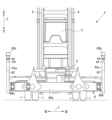
図1および図2に示すように、本実施形態に係るフォークリフトFは、前後の車輪1と、車輪1に支持された車体2と、車体2の上方に設けられた運転席3と、車体2の前方に設けられた左右一対のマスト4と、キャリッジ5と、スプレッダ6と、左右一対のリフトシリンダ7と、制御部8と、を備えている。
As shown in FIGS. 1 and 2, a forklift F according to the present embodiment includes front and
左右一対のマスト4は、上下方向に延びており、スプレッダ6は、キャリッジ5を介してマスト4に連結されている。スプレッダ6は、左右一対のリフトシリンダ7によってマスト4に沿って昇降させられる。
A pair of left and
図2および図3に示すように、スプレッダ6は、レール60(60a、60b)と、左右一対の支柱62と、ツイストロックピン63と、所定距離検知部64と、係止検知部65と、を有する。
As shown in FIGS. 2 and 3, the
レール60は、伸縮しない固定レール60aと、固定レール60aの左右端から左右方向に伸縮する左右一対の伸縮レール60bと、を有する。固定レール60aは、キャリッジ5を介して、マスト4に連結されている。
The
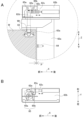
左右一対の支柱62は、図3Aおよび図3Bに示されるように、支柱本体62aと、シリンダボックス62bと、ツイストロックシリンダ62cと、ツイストロックホルダ62dと、カム62eと、を有する。
As shown in FIGS. 3A and 3B, the pair of left and
左右の支柱本体62aは、上下方向に延びるとともに、伸縮レール60bの外側端部にそれぞれ連結されている。シリンダボックス62bは、支柱本体62aの上方に設けられている。
The left and right column
ツイストロックシリンダ62cは、前後方向に延びるとともに、シリンダボックス62b内に設けられている。ツイストロックシリンダ62cは、油圧シリンダであって、油圧によって前後方向に伸縮させられる。ツイストロックホルダ62dは、上下方向に延びるとともに、カム62eを介してツイストロックシリンダ62cに連結されている。図3Aおよび図3Bに示すように、ツイストロックシリンダ62cは、伸縮することによりツイストロックホルダ62dを90°回動させる。
The
ツイストロックピン63は、ツイストロックホルダ62dの下端に固定されている。ツイストロックピン63は、下端に向かって先細るテーパ状に形成されるとともに、2点鎖線で示すように、ツイストロックホルダ62dよりも水平方向に張り出した張り出し部63aを有する。ツイストロックピン63が、本発明の「係止部」に相当する。図3Aに示すように、ツイストロックピン63は、ツイストロックシリンダ62cが伸縮することにより、ツイストロックホルダ62dとともに90°回動させられる。これにより、ツイストロックピン63は、コンテナWに設けられた係止穴Whに係止または係止解除させられる。
The
図3Aに示すように、所定距離検知部64は、近接センサであって、左右の支柱62にそれぞれ埋設されている。所定距離検知部64は、左右の支柱62の前面と他の物体との距離Pが所定の距離内であるか否かを検知する。当該所定の距離は、例えば、0mm~10mmの間で設定してもよい。これにより、所定距離検知部64は、支柱62がコンテナWに押し当てられる前に、コンテナWと支柱62との近接または接触を検知することができる。
As shown in FIG. 3A, the
係止検知部65は、本実施形態では、2つの近接センサ65a、65bを有する。当該2つの近接センサ65a、65bは、図3Aおよび図3Bに示すように、シリンダボックス62b内かつツイストロックホルダ62dの上方において、前後方向に互いに間隔をおいて設けられている。ツイストロックシリンダ62cの上面には、平面視逆L字状の検知プレート65cが設けられており、検知プレート65cは、ツイストロックシリンダ62cの伸縮によって前後方向にスライドさせられる。係止検知部65は、2つの近接センサ65a、65bのうちのいずれが検知プレート65cを検知しているかに基づいて、ツイストロックピン63の伸縮状態を検知する。これにより、係止検知部65は、ツイストロックピン63の向きを検知し、それによってツイストロックピン63がコンテナWに係止されているか否かを検知する。
The locking
図4は、本実施形態に係るフォークリフトFの油圧装置の一部構成を示している。図4に示すように、フォークリフトFは、タンク9と、給排路10と、パイロットバルブ11と、コントロールバルブ12と、ソレノイドバルブ13と、圧力センサ14と、をさらに備えている。
FIG. 4 shows a partial configuration of the hydraulic system of the forklift F according to this embodiment. As shown in FIG. 4 , the forklift F further includes a tank 9 , a supply/
タンク9は、作動油を収容している。給排路10は、タンク9とリフトシリンダ7との間に設けられており、作動油は、この給排路10を通ってリフトシリンダ7に供給される。
The tank 9 contains working oil. A supply/
パイロットバルブ11は、運転席3に設けられた操作部30(図5参照)の操作に基づいて、コントロールバルブ12への作動油の給排を切り替える。
The
ソレノイドバルブ13は、パイロットバルブ11およびタンク9と、コントロールバルブ12との間の給排路10に設けられており、パイロットバルブ11およびタンク9からコントロールバルブ12への給排路10を開閉する。
The
コントロールバルブ12は、パイロットバルブ11を介した作動油の供給に基づいて、リフトシリンダ7に供給する作動油の給排を切り替える。言い換えると、コントロールバルブ12は、ソレノイドバルブ13によって、パイロットバルブ11を介した作動油の供給が停止されると動作することができない。
The
圧力センサ14は、リフトシリンダ7とコントロールバルブ12との間の給排路10近傍に設けられており、当該給排路10の油圧を検出しこの油圧が所定油圧以上か否かを検知する。これにより、圧力センサ14は、リフトシリンダ7によってリフトされたコンテナWが所定重量以上であるか否かを検知する。
The
所定油圧は、フォークリフトFが所定重量のコンテナWをリフトしたときの油圧に設定されている。すなわち、圧力センサ14によって所定油圧以上の油圧が検知されたとき、フォークリフトFは、所定重量以上のコンテナWをリフトしていることになる。所定重量は、例えば、6,000kgでもよい。
The predetermined hydraulic pressure is set to the hydraulic pressure when the forklift F lifts the container W having a predetermined weight. That is, when the
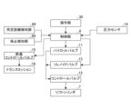
図5は、フォークリフトFの各構成の機能ブロック図である。図5に示すように、フォークリフトFは、さらに、前進コントロールバルブ15と、トランスミッション16とを備えている。図6は、制御部8の構成の一部を示す電気回路図である。図6に示すように、制御部8は、前進制御ソレノイド80と、後進制御ソレノイド81と、3つのリレー82、83、84と、所定距離検知部スイッチ85と、係止検知部スイッチ86と、圧力スイッチ87と、を有する。なお、図6中の3つのリレー82、83、84のリレーの向きは、各リレーの励磁コイルが励磁されていないときの向きである。
FIG. 5 is a functional block diagram of each component of the forklift F. As shown in FIG. As shown in FIG. 5, the forklift F further includes a
トランスミッション16は、油圧制御に基づいて前進、ニュートラルおよび後進を切り替えられる。この油圧制御は、前進コントロールバルブ15、後進コントロールバルブ(図示略)を介して行われる。この前進コントロールバルブ15を制御するのが前進制御ソレノイド80であり、後進コントロールバルブを制御するのが後進制御ソレノイド81である。
The
図5に示すように、制御部8は、所定距離検知部64、係止検知部65および圧力センサ14の出力を受ける。制御部8は、所定距離検知部64によって支柱62前面とコンテナWとの距離Pが所定距離以下であると検知されると、前進制御ソレノイド80の通電を遮断して前進コントロールバルブ15の動作を停止させる。より詳しくは、図6を参照して説明する。
As shown in FIG. 5 , the
図6に示すように、操作部30によって前進(F)に切り替えられると、電流は、前進制御ソレノイド80およびリレー82を流れ、前進制御ソレノイド80を作動させる。このとき、所定距離検知部64によって左右いずれかの支柱62前面とコンテナWとの距離Pが所定距離以下であると検知されると、所定距離検知部スイッチ85がONになりリレー82の励磁コイルに電流が流れ、リレー82が所定距離検知部スイッチ85側端子(上側端子)に切り替えられる。これにより、前進制御ソレノイド80がオープンになり通電が遮断され、その結果、フォークリフトFの前進が停止される。これにより、フォークリフトFは、ユーザUが目視を誤って支柱62をコンテナWに押し当て過ぎてスプレッダ6を破損させることを防止することができる。
As shown in FIG. 6 , when the
続いて、制御部8は、係止検知部65によってツイストロックピン63のコンテナWへの係止が検知されると、前進制御ソレノイド80の通電を再開する。図6を参照してさらに詳しく説明すると、係止検知部65によって、ツイストロックピン63のコンテナWへの係止が検知されると、係止検知部スイッチ86がONになりリレー83の励磁コイルに電流が流れ、リレー83が係止検知部スイッチ86側端子(上側端子)に切り替えられる。これにより、リレー82の励磁コイルへの通電が遮断され、リレー82が所定距離検知部スイッチ85側端子の反対側端子(下側端子)に切り替えられる。これにより、前進制御ソレノイド80が再び通電状態になされ、その結果、フォークリフトFの前進停止が解除される。
Subsequently, when the
さらに、制御部8は、圧力センサ14によって所定油圧以上の油圧が検知されると、ソレノイドバルブ13への通電を遮断する。図6を参照してさらに詳しく説明すると、圧力センサ14によって所定油圧以上の油圧が検知されると、圧力スイッチ87がONになり、リレー84の励磁コイルに電流が流れ、リレー84が圧力スイッチ87側端子(上側端子)に切り替えられる。これにより、ソレノイドバルブ13がオープンになり、ソレノイドバルブ13への通電が遮断される。その結果、ソレノイドバルブ13は、給排路10を閉じ、パイロットバルブ11を介したコントロールバルブ12への作動油の供給を停止して、コントロールバルブ12の動作を停止させる。これにより、リフトシリンダ7の伸長が停止されるので、フォークリフトFは、ユーザUがフォークリフトFによって実入りのコンテナWを持ち上げようとしてスプレッダ6を破損させることを防止することができる。なお、このとき、図6に示すように、制御部8は、警告ブザー88、警告ランプ89をさらに有し、圧力スイッチ87がONになると、警告ブザー88および警告ランプ89に通電され、警告ブザー88の音声、および警告ランプ89の光によってユーザUに報知してもよい。
Furthermore, when the
次に、図7のフロー図を参照して、コンテナW運搬時におけるフォークリフトFの上記スプレッダ破損防止機能について説明する。 Next, with reference to the flowchart of FIG. 7, the spreader breakage prevention function of the forklift F during transportation of the container W will be described.
(1)コンテナWを運搬するために、フォークリフトFは、ツイストロックピン63をコンテナWの上方まで上昇させた状態で、コンテナWに向かって前進する(ステップS1)。
(1) To transport the container W, the forklift F moves forward toward the container W while the
(2)フォークリフトFは、所定距離検知部64によって支柱62前面とコンテナWとの距離Pが所定距離内であると検知されると(ステップS2のYes)、制御部8によって前進を停止させられる(ステップS3)。
(2) When the predetermined
(3)次いで、フォークリフトFは、スプレッダ6を下降させツイストロックピン63をコンテナWの係止穴Whに挿入するとともに、ツイストロックピン63を回転させコンテナWに係止させる。係止検知部65によってツイストロックピン63のコンテナWへの係止が検知されると(ステップS4のYes)、フォークリフトFの前進停止が解除される(ステップS5)。
(3) Next, the forklift F lowers the
(4)次いで、フォークリフトFは、リフトシリンダ7によってコンテナWをリフトする(ステップS6)。 (4) Next, the forklift F lifts the container W with the lift cylinder 7 (step S6).
(5)次いで、フォークリフトFは、圧力センサ14によって所定重量以上のコンテナWが検知されないと(ステップS7のNo)、そのまま所定高さまでコンテナWをリフトしリフト動作を完了する(ステップS8)。一方、フォークリフトFは、圧力センサ14によって所定重量以上のコンテナWが検知されると、制御部8によってリフトシリンダ7によるリフト動作を停止させられる。
(5) Next, if the
フォークリフトFは、上記スプレッダ破損防止機能を備えていることにより、ユーザUの目視に頼らず適切に支柱62をコンテナWに近接させることができ、しかも、実入りのコンテナWを持ち上げようとしたときにはリフト動作を停止することにより、オーバーロードによるスプレッダ6の破損を防止することができる。
Since the forklift F has the spreader breakage prevention function, the
以上、本発明の一実施形態に係るフォークリフトFについて説明してきたが、本発明に係るフォークリフトは、上記実施形態に限定されるものではない。例えば、本発明に係る制御部8は、他の公知の技術によって、車体2の前進を停止したり解除したり、リフトシリンダ7の伸縮を停止させてもよい。
Although the forklift F according to one embodiment of the present invention has been described above, the forklift according to the present invention is not limited to the above embodiment. For example, the
F フォークリフト
W コンテナ
Wh 係止穴
U ユーザ
1 車輪
2 車体
3 運転席
30 操作部
4 マスト
5 キャリッジ
6 スプレッダ
60 レール
60a 固定レール
60b 伸縮レール
62 支柱
62a 支柱本体
62b シリンダボックス
62c ツイストロックシリンダ
62d ツイストロックホルダ
62e カム
63 ツイストロックピン(係止部)
64 所定距離検知部
65 係止検知部
65a、65b 近接センサ
65c 検知プレート
7 リフトシリンダ
8 制御部
80 前進制御ソレノイド
81 後進制御ソレノイド
82、83、84 リレー
85 所定距離検知部スイッチ
86 係止検知部スイッチ
87 圧力スイッチ
88 警告ブザー
89 警告ランプ
9 タンク
10 給排路
11 パイロットバルブ
12 コントロールバルブ
13 ソレノイドバルブ
14 圧力センサ
15 前進コントロールバルブ
16 トランスミッション
F Forklift W Container Wh Locking
64
Claims (4)
前記車体の前方において上下に延びるマストと、
前記マストに沿って昇降させられるスプレッダと、
制御部と、を備え、
前記スプレッダは、
左右方向に延びるレールと、
前記レールの左右端にそれぞれ設けられ、上下方向に延びる左右一対の支柱と、
前記左右一対の支柱の前面と他の物体との距離が所定の距離内であるか否かを検知する所定距離検知部と、
前記左右一対の支柱にそれぞれ設けられ、コンテナに係止される係止部と、
前記係止部が前記コンテナに係止されたか否かを検知する係止検知部と、を有し、
前記制御部は、前記所定距離検知部によって前記左右一対の支柱の前面と他の物体との距離が所定の距離内であると検知されると前記車体の前進を停止させ、前記係止検知部によって前記係止部が前記コンテナに係止されたと検知されると前記前進の停止を解除する
ことを特徴とするスプレッダ破損防止機能を備えたフォークリフト。 a vehicle body;
a mast extending vertically in front of the vehicle body;
a spreader that is raised and lowered along the mast;
a control unit;
The spreader is
a rail extending in the left-right direction;
a pair of left and right struts respectively provided at left and right ends of the rail and extending in the vertical direction;
a predetermined distance detection unit that detects whether or not the distance between the front surfaces of the pair of left and right pillars and another object is within a predetermined distance;
a locking portion provided on each of the pair of left and right pillars and locked to the container;
a locking detection unit that detects whether or not the locking unit is locked to the container;
The control unit stops forward movement of the vehicle body when the predetermined distance detection unit detects that the distance between the front surfaces of the pair of left and right struts and another object is within a predetermined distance, and stops the vehicle body from moving forward. a forklift equipped with a spreader breakage prevention function, wherein the stopping of the forward movement is released when it is detected that the locking portion is locked to the container by a.
ことを特徴とする請求項1に記載のフォークリフト。 2. The forklift truck according to claim 1, wherein the predetermined distance detection unit is a proximity sensor and is provided on the column.
前記作動油を収容するタンクと、
前記リフトシリンダと前記タンクとの間に設けられた前記作動油の給排路と
前記給排路に設けられ、前記リフトシリンダの動作を制御するコントロールバルブと、
前記給排路の油圧を検出し、前記リフトシリンダによってリフトされた前記コンテナが所定重量以上であるか否かを検知する圧力センサと、
前記リフトシリンダによってリフトされた前記コンテナが所定重量以上のコンテナであるとき、前記コントロールバルブの動作を停止させて前記リフトシリンダの伸長を停止させるコントロールバルブ停止部と、をさらに備える
ことを特徴とする請求項1または2に記載のフォークリフト。 a lift cylinder that expands and contracts with hydraulic oil to raise and lower the rail;
a tank containing the hydraulic oil;
a hydraulic oil supply/discharge path provided between the lift cylinder and the tank; a control valve provided in the supply/discharge path for controlling the operation of the lift cylinder;
a pressure sensor that detects the hydraulic pressure of the supply/discharge path and detects whether or not the container lifted by the lift cylinder has a predetermined weight or more;
a control valve stop unit for stopping the operation of the control valve to stop the extension of the lift cylinder when the container lifted by the lift cylinder is a container having a predetermined weight or more. A forklift according to claim 1 or 2.
前記ソレノイドバルブは、前記タンクと前記コントロールバルブとの間の前記給排路に設けられており、
前記コントロールバルブを介した前記リフトシリンダへの前記作動油の供給は、前記ソレノイドバルブを経由して行われており、
前記ソレノイドバルブは、前記リフトシリンダによってリフトされた前記コンテナが所定重量以上のコンテナであるとき、前記タンクから前記コントロールバルブへの前記作動油の供給を遮断する
ことを特徴とする請求項3に記載のフォークリフト。 The control valve stop portion is a solenoid valve,
The solenoid valve is provided in the supply/discharge path between the tank and the control valve,
supply of the hydraulic oil to the lift cylinder via the control valve is performed via the solenoid valve;
4. The solenoid valve according to claim 3, wherein the solenoid valve cuts off the supply of the hydraulic oil from the tank to the control valve when the container lifted by the lift cylinder has a predetermined weight or more. forklift.
Priority Applications (1)
| Application Number | Priority Date | Filing Date | Title |
|---|---|---|---|
| JP2021143886A JP7311237B2 (en) | 2021-09-03 | 2021-09-03 | Forklift with spreader damage prevention function |
Applications Claiming Priority (1)
| Application Number | Priority Date | Filing Date | Title |
|---|---|---|---|
| JP2021143886A JP7311237B2 (en) | 2021-09-03 | 2021-09-03 | Forklift with spreader damage prevention function |
Publications (2)
| Publication Number | Publication Date |
|---|---|
| JP2023037249A JP2023037249A (en) | 2023-03-15 |
| JP7311237B2 true JP7311237B2 (en) | 2023-07-19 |
Family
ID=85509402
Family Applications (1)
| Application Number | Title | Priority Date | Filing Date |
|---|---|---|---|
| JP2021143886A Active JP7311237B2 (en) | 2021-09-03 | 2021-09-03 | Forklift with spreader damage prevention function |
Country Status (1)
| Country | Link |
|---|---|
| JP (1) | JP7311237B2 (en) |
Citations (7)
| Publication number | Priority date | Publication date | Assignee | Title |
|---|---|---|---|---|
| US4521044A (en) | 1983-03-21 | 1985-06-04 | Rpc Corporation | Twistlock operator |
| JP2007276943A (en) | 2006-04-05 | 2007-10-25 | Toyota Industries Corp | Simultaneous operation restriction mechanism and fork lift |
| JP4191298B2 (en) | 1997-12-19 | 2008-12-03 | シーメンス アクチェンゲゼルシャフト | Fuel / air mixing device for combustion devices |
| CN202144434U (en) | 2011-07-14 | 2012-02-15 | 三一集团有限公司 | Fork truck and suspension tool thereof |
| JP5449752B2 (en) | 2008-12-03 | 2014-03-19 | コンビ株式会社 | stroller |
| JP5523382B2 (en) | 2010-03-19 | 2014-06-18 | 富士フイルム株式会社 | Gas barrier film manufacturing method and gas barrier film |
| JP6367599B2 (en) | 2013-11-22 | 2018-08-01 | 日東電工株式会社 | Double-sided adhesive sheet |
Family Cites Families (6)
| Publication number | Priority date | Publication date | Assignee | Title |
|---|---|---|---|---|
| JPS5449752A (en) * | 1977-09-26 | 1979-04-19 | Komatsu Forklift Kk | Overload preventive apparatus for material handling vehicle |
| JPS6030310Y2 (en) * | 1978-08-02 | 1985-09-11 | 株式会社豊田自動織機製作所 | Container spreader safety device |
| JPH0638877Y2 (en) * | 1986-10-24 | 1994-10-12 | 株式会社豊田自動織機製作所 | Manned forklift braking system |
| JPH04191298A (en) * | 1990-11-26 | 1992-07-09 | Toyota Autom Loom Works Ltd | Container stopper for container spreader |
| JPH0756319Y2 (en) * | 1990-11-29 | 1995-12-25 | 小松フォークリフト株式会社 | Obstacle warning device for spreader |
| JPH1143299A (en) * | 1997-07-25 | 1999-02-16 | Toyo Umpanki Co Ltd | Carrier vehicle |
-
2021
- 2021-09-03 JP JP2021143886A patent/JP7311237B2/en active Active
Patent Citations (7)
| Publication number | Priority date | Publication date | Assignee | Title |
|---|---|---|---|---|
| US4521044A (en) | 1983-03-21 | 1985-06-04 | Rpc Corporation | Twistlock operator |
| JP4191298B2 (en) | 1997-12-19 | 2008-12-03 | シーメンス アクチェンゲゼルシャフト | Fuel / air mixing device for combustion devices |
| JP2007276943A (en) | 2006-04-05 | 2007-10-25 | Toyota Industries Corp | Simultaneous operation restriction mechanism and fork lift |
| JP5449752B2 (en) | 2008-12-03 | 2014-03-19 | コンビ株式会社 | stroller |
| JP5523382B2 (en) | 2010-03-19 | 2014-06-18 | 富士フイルム株式会社 | Gas barrier film manufacturing method and gas barrier film |
| CN202144434U (en) | 2011-07-14 | 2012-02-15 | 三一集团有限公司 | Fork truck and suspension tool thereof |
| JP6367599B2 (en) | 2013-11-22 | 2018-08-01 | 日東電工株式会社 | Double-sided adhesive sheet |
Also Published As
| Publication number | Publication date |
|---|---|
| JP2023037249A (en) | 2023-03-15 |
Similar Documents
| Publication | Publication Date | Title |
|---|---|---|
| JP5055439B2 (en) | Transport vehicle | |
| JP7311237B2 (en) | Forklift with spreader damage prevention function | |
| US7278508B2 (en) | Control system of industrial truck and controlling method of the same | |
| JP4806984B2 (en) | forklift | |
| JP5542386B2 (en) | forklift | |
| JP2007276943A (en) | Simultaneous operation restriction mechanism and fork lift | |
| CN108698532B (en) | Transport vehicle | |
| JP5280138B2 (en) | Car with lifting platform | |
| JP4647269B2 (en) | forklift | |
| JP2003054887A (en) | Forklift truck | |
| JP5073543B2 (en) | Control device for work vehicle | |
| JP7107151B2 (en) | Hydraulic drives for industrial vehicles | |
| JP6927656B1 (en) | Forklift with ram | |
| JP4162387B2 (en) | Safety equipment for cargo handling vehicles | |
| JPH04361999A (en) | Side shifting equipment in fork life truck | |
| JP7222646B2 (en) | transportation vehicle | |
| JP7123725B2 (en) | transportation vehicle | |
| JP7140622B2 (en) | transportation vehicle | |
| JP7123727B2 (en) | transportation vehicle | |
| US20230406683A1 (en) | Systems and Methods for Material Handling Vehicle | |
| JP7123726B2 (en) | transportation vehicle | |
| JP7181041B2 (en) | transportation vehicle | |
| JP7165479B2 (en) | transportation vehicle | |
| JP2006225091A (en) | Fork lift | |
| JP6324272B2 (en) | Kant Correction Cylinder Protection Device for Railroad Vehicles |
Legal Events
| Date | Code | Title | Description |
|---|---|---|---|
| A621 | Written request for application examination |
Free format text: JAPANESE INTERMEDIATE CODE: A621 Effective date: 20220927 |
|
| A977 | Report on retrieval |
Free format text: JAPANESE INTERMEDIATE CODE: A971007 Effective date: 20230627 |
|
| TRDD | Decision of grant or rejection written | ||
| A01 | Written decision to grant a patent or to grant a registration (utility model) |
Free format text: JAPANESE INTERMEDIATE CODE: A01 Effective date: 20230705 |
|
| A61 | First payment of annual fees (during grant procedure) |
Free format text: JAPANESE INTERMEDIATE CODE: A61 Effective date: 20230705 |
|
| R150 | Certificate of patent or registration of utility model |
Ref document number: 7311237 Country of ref document: JP Free format text: JAPANESE INTERMEDIATE CODE: R150 |