JP7305022B2 - push switch - Google Patents

push switch Download PDF

Info

Publication number
JP7305022B2
JP7305022B2 JP2022501687A JP2022501687A JP7305022B2 JP 7305022 B2 JP7305022 B2 JP 7305022B2 JP 2022501687 A JP2022501687 A JP 2022501687A JP 2022501687 A JP2022501687 A JP 2022501687A JP 7305022 B2 JP7305022 B2 JP 7305022B2
Authority
JP
Japan
Prior art keywords
housing
axial direction
push switch
terminal
bottom wall
Prior art date
Legal status (The legal status is an assumption and is not a legal conclusion. Google has not performed a legal analysis and makes no representation as to the accuracy of the status listed.)
Active
Application number
JP2022501687A
Other languages
Japanese (ja)
Other versions
JPWO2021166478A1 (en
Inventor
啓志 小原
Current Assignee (The listed assignees may be inaccurate. Google has not performed a legal analysis and makes no representation or warranty as to the accuracy of the list.)
Alps Alpine Co Ltd
Original Assignee
Alps Electric Co Ltd
Alps Alpine Co Ltd
Priority date (The priority date is an assumption and is not a legal conclusion. Google has not performed a legal analysis and makes no representation as to the accuracy of the date listed.)
Filing date
Publication date
Application filed by Alps Electric Co Ltd, Alps Alpine Co Ltd filed Critical Alps Electric Co Ltd
Publication of JPWO2021166478A1 publication Critical patent/JPWO2021166478A1/ja
Application granted granted Critical
Publication of JP7305022B2 publication Critical patent/JP7305022B2/en
Active legal-status Critical Current
Anticipated expiration legal-status Critical

Links

Images

Classifications

    • HELECTRICITY
    • H01ELECTRIC ELEMENTS
    • H01HELECTRIC SWITCHES; RELAYS; SELECTORS; EMERGENCY PROTECTIVE DEVICES
    • H01H13/00Switches having rectilinearly-movable operating part or parts adapted for pushing or pulling in one direction only, e.g. push-button switch
    • H01H13/02Details
    • H01H13/12Movable parts; Contacts mounted thereon
    • H01H13/14Operating parts, e.g. push-button
    • HELECTRICITY
    • H01ELECTRIC ELEMENTS
    • H01HELECTRIC SWITCHES; RELAYS; SELECTORS; EMERGENCY PROTECTIVE DEVICES
    • H01H13/00Switches having rectilinearly-movable operating part or parts adapted for pushing or pulling in one direction only, e.g. push-button switch
    • H01H13/02Details
    • H01H13/26Snap-action arrangements depending upon deformation of elastic members
    • H01H13/48Snap-action arrangements depending upon deformation of elastic members using buckling of disc springs
    • HELECTRICITY
    • H01ELECTRIC ELEMENTS
    • H01HELECTRIC SWITCHES; RELAYS; SELECTORS; EMERGENCY PROTECTIVE DEVICES
    • H01H13/00Switches having rectilinearly-movable operating part or parts adapted for pushing or pulling in one direction only, e.g. push-button switch
    • H01H13/02Details
    • H01H13/04Cases; Covers
    • HELECTRICITY
    • H01ELECTRIC ELEMENTS
    • H01HELECTRIC SWITCHES; RELAYS; SELECTORS; EMERGENCY PROTECTIVE DEVICES
    • H01H13/00Switches having rectilinearly-movable operating part or parts adapted for pushing or pulling in one direction only, e.g. push-button switch
    • H01H13/02Details
    • H01H13/12Movable parts; Contacts mounted thereon
    • H01H13/20Driving mechanisms
    • HELECTRICITY
    • H01ELECTRIC ELEMENTS
    • H01HELECTRIC SWITCHES; RELAYS; SELECTORS; EMERGENCY PROTECTIVE DEVICES
    • H01H2203/00Form of contacts
    • H01H2203/036Form of contacts to solve particular problems
    • H01H2203/038Form of contacts to solve particular problems to be bridged by a dome shaped contact
    • HELECTRICITY
    • H01ELECTRIC ELEMENTS
    • H01HELECTRIC SWITCHES; RELAYS; SELECTORS; EMERGENCY PROTECTIVE DEVICES
    • H01H2205/00Movable contacts
    • H01H2205/016Separate bridge contact
    • H01H2205/024Means to facilitate positioning
    • H01H2205/03Apertured plate
    • HELECTRICITY
    • H01ELECTRIC ELEMENTS
    • H01HELECTRIC SWITCHES; RELAYS; SELECTORS; EMERGENCY PROTECTIVE DEVICES
    • H01H2215/00Tactile feedback
    • H01H2215/004Collapsible dome or bubble
    • H01H2215/018Collapsible dome or bubble unstressed in open position of switch
    • HELECTRICITY
    • H01ELECTRIC ELEMENTS
    • H01HELECTRIC SWITCHES; RELAYS; SELECTORS; EMERGENCY PROTECTIVE DEVICES
    • H01H2221/00Actuators
    • H01H2221/008Actuators other then push button
    • H01H2221/016Lever; Rocker
    • HELECTRICITY
    • H01ELECTRIC ELEMENTS
    • H01HELECTRIC SWITCHES; RELAYS; SELECTORS; EMERGENCY PROTECTIVE DEVICES
    • H01H2221/00Actuators
    • H01H2221/05Force concentrator; Actuating dimple

Description

本発明は、プッシュスイッチに関する。 The present invention relates to push switches.

従来より、長手方向及び短手方向を有する樹脂製の筐体の底壁にインサート成型により埋め込まれる固定接点部材と、筐体の収容部に設けられる可動接点部材とを含むスイッチがある。固定接点部材は、長手方向の端部に設けられる端子を有し、端子の短手方向の両側には、長手方向における中央側に向けて上側に折り曲げられた折り曲げ部が設けられている。折り曲げ部は、筐体の壁部にインサート成型により埋め込まれている(例えば、特許文献1参照)。 2. Description of the Related Art Conventionally, there is a switch including a fixed contact member embedded by insert molding in the bottom wall of a resin-made housing having a longitudinal direction and a lateral direction, and a movable contact member provided in a housing portion of the housing. The fixed contact member has terminals provided at the ends in the longitudinal direction, and bent portions that are bent upward toward the center in the longitudinal direction are provided on both sides of the terminal in the lateral direction. The bent portion is embedded in the wall portion of the housing by insert molding (see Patent Document 1, for example).

特開2019-061747号公報JP 2019-061747 A

ところで従来のスイッチは、折り曲げ部が端子の両端の角に存在しないため、筐体に想定以上の力が加わった際に、端子強度が足りなくなるおそれがあり、更なる強度アップが求められていた。 By the way, since conventional switches do not have bent portions at the corners of both ends of the terminals, there is a risk that the strength of the terminals will be insufficient when more force than expected is applied to the housing, and there has been a demand for further strengthening. .

そこで、より剛性の高いプッシュスイッチを提供することを目的とする。 Therefore, it is an object of the present invention to provide a push switch with higher rigidity.

本発明の実施の形態のプッシュスイッチは、底壁と側壁とを有し、平面視で第1軸方向及び第2軸方向に延在する筐体と、可動接点部材と接触する固定接点部材であって、前記筐体の底壁にインサート成型により埋め込まれる固定接点部材とを含むプッシュスイッチにおいて、前記固定接点部材は、前記筐体の前記第1軸方向における第1端部から外側に露出される第1端子と、前記第1端子の前記第2軸方向における両端が上側に向かって折り曲げられて延在し、前記筐体の側壁及び/又は底壁にインサート成型により埋め込まれる一対の第1延在部とを有する。 A push switch according to an embodiment of the present invention comprises a housing having a bottom wall and a side wall and extending in a first axial direction and a second axial direction in a plan view, and a fixed contact member that contacts a movable contact member. and a fixed contact member embedded in the bottom wall of the housing by insert molding, wherein the fixed contact member is exposed to the outside from a first end of the housing in the first axial direction. and a pair of first terminals that are bent upward at both ends of the first terminal in the second axial direction and are embedded in the side wall and/or the bottom wall of the housing by insert molding. and an extension.

より剛性の高いプッシュスイッチを提供することができる。 A push switch with higher rigidity can be provided.

実施の形態1のプッシュスイッチ100を示す斜視図である。1 is a perspective view showing push switch 100 of Embodiment 1. FIG. プッシュスイッチ100の分解図である。2 is an exploded view of push switch 100. FIG. 筐体110にインサート成型により埋め込まれた金属プレート120A、120Bを透過的に示す図である。4 is a diagram transparently showing metal plates 120A and 120B embedded in the housing 110 by insert molding. FIG. 金属プレート120A、120Bを示す図である。FIG. 4 shows metal plates 120A and 120B; 押圧部材140の裏面側を示す図である。4 is a diagram showing the back side of the pressing member 140. FIG. 図1におけるA1-A1矢視断面を示す図である。FIG. 2 is a diagram showing a cross section taken along line A1-A1 in FIG. 1; 図1におけるB1-B1矢視断面を示す図である。FIG. 2 is a view showing a cross section taken along line B1-B1 in FIG. 1; プッシュスイッチ100のFS特性を示す図である。4 is a diagram showing FS characteristics of the push switch 100; FIG. 実施の形態2のプッシュスイッチ200を示す斜視図である。FIG. 11 is a perspective view showing a push switch 200 according to Embodiment 2; プッシュスイッチ200の分解図である。2 is an exploded view of push switch 200. FIG. 押圧部材240の裏面側を示す図である。4 is a diagram showing the back side of the pressing member 240. FIG. 金属プレート220A、220B、220Cの構造を示す図である。FIG. 4 is a diagram showing the structure of metal plates 220A, 220B, and 220C; 図9におけるA-A矢視断面を示す図である。FIG. 10 is a view showing a cross section taken along line AA in FIG. 9; 図9におけるA-A矢視断面を示す図である。FIG. 10 is a view showing a cross section taken along line AA in FIG. 9; 図9におけるA-A矢視断面を示す図である。FIG. 10 is a view showing a cross section taken along line AA in FIG. 9; 図9におけるB-B矢視断面を示す図である。FIG. 10 is a view showing a cross section taken along line BB in FIG. 9; 図9におけるB-B矢視断面を示す図である。FIG. 10 is a view showing a cross section taken along line BB in FIG. 9; 図9におけるB-B矢視断面を示す図である。FIG. 10 is a view showing a cross section taken along line BB in FIG. 9; プッシュスイッチ200のFS特性を示す図である。4 is a diagram showing FS characteristics of the push switch 200; FIG.

以下、本発明のプッシュスイッチを適用した実施の形態について説明する。 Embodiments to which the push switch of the present invention is applied will be described below.

<実施の形態1>
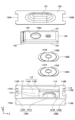
図1は、実施の形態1のプッシュスイッチ100を示す斜視図である。図2は、プッシュスイッチ100の分解図である。以下では、XYZ座標系を定義して説明する。また、以下では、説明の便宜上、-Z方向側を下側又は下、+Z方向側を上側又は上と称すが、普遍的な上下関係を表すものではない。
<Embodiment 1>
FIG. 1 is a perspective view showing push switch 100 of Embodiment 1. FIG. FIG. 2 is an exploded view of the push switch 100. As shown in FIG. An XYZ coordinate system will be defined and explained below. Also, hereinafter, for convenience of explanation, the −Z direction side is referred to as the lower side or the lower side, and the +Z direction side is referred to as the upper side or the upper side, but this does not represent a universal vertical relationship.

プッシュスイッチ100は、筐体110、金属プレート120A、120B、メタルコンタクト130A、リーフスプリング130B、押圧部材140、及びインシュレータ150を含む。 Push switch 100 includes housing 110 , metal plates 120 A and 120 B, metal contact 130 A, leaf spring 130 B, pressing member 140 and insulator 150 .

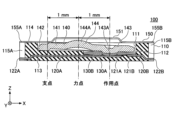
以下では、金属プレート120A、120Bについては、図1及び図2に加えて図3及び図4を用いて説明する。図3は、筐体110にインサート成型により埋め込まれた金属プレート120A、120Bを透過的に示す図である。図4は、金属プレート120A、120Bを示す図である。また、押圧部材140については、図2に加えて図5を用いて説明する。図5は、押圧部材140の裏面側を示す図である。また、断面構造については、図1におけるA1-A1矢視断面を示す図6及び図7を用いて説明する。A1-A1矢視断面は、プッシュスイッチ100のY方向の中央でXZ平面に沿った切断面で得る断面である。また、プッシュスイッチ100は、一例として、X方向の長さがY方向の長さよりも長い形状を有する。このため、筐体110、押圧部材140、及びインシュレータ150も一例として、X方向の長さがY方向の長さよりも長い形状を有する。 The metal plates 120A and 120B will be described below using FIGS. 3 and 4 in addition to FIGS. 1 and 2. FIG. FIG. 3 is a view transparently showing metal plates 120A and 120B embedded in housing 110 by insert molding. FIG. 4 is a diagram showing metal plates 120A and 120B. Further, the pressing member 140 will be described using FIG. 5 in addition to FIG. FIG. 5 is a diagram showing the back side of the pressing member 140. As shown in FIG. Also, the cross-sectional structure will be described with reference to FIGS. A1-A1 cross section is a cross section taken along the XZ plane at the center of the push switch 100 in the Y direction. In addition, the push switch 100 has, as an example, a shape in which the length in the X direction is longer than the length in the Y direction. For this reason, the housing 110, the pressing member 140, and the insulator 150 also have, as an example, a shape in which the length in the X direction is longer than the length in the Y direction.

以下では、プッシュスイッチ100、筐体110、押圧部材140、及びインシュレータ150については、X方向が長手方向であり、Y方向が短手方向である。X方向は第1軸方向の一例であり、Y方向は第2軸方向の一例である。また、筐体110の-X方向の端部は、第1軸方向における第1端部の一例であり、筐体110の+X方向の端部は、第1軸方向における第2端部の一例である。 In the following description, the push switch 100, the housing 110, the pressing member 140, and the insulator 150 are longitudinal in the X direction and lateral in the Y direction. The X direction is an example of a first axis direction, and the Y direction is an example of a second axis direction. The −X direction end of the housing 110 is an example of a first end in the first axis direction, and the +X direction end of the housing 110 is an example of a second end in the first axis direction. is.

プッシュスイッチ100は、オフ(非導通状態)の時には、メタルコンタクト130Aは金属プレート120B(周辺固定接点121B)には接触しているが、金属プレート120A(中央固定接点121A)には接触していない。すなわち、金属プレート120Aと金属プレート120Bとは電気的に接続されていない状態である。また、プッシュスイッチ100は、インシュレータ150を下方向に押圧することによって、押圧部材140およびリーフスプリング130Bを介してメタルコンタクト130Aを押圧し、メタルコンタクト130Aが反転動作を行い金属プレート120Aに接触して、金属プレート120Aと金属プレート120Bとはメタルコンタクト130Aを介して電気的に接続され、オン(導通状態)になるスイッチである。メタルコンタクト130Aを金属プレート120Aに接触させるためにインシュレータ150を押すストロークは、非常に短く、0.05mmである。また、メタルコンタクト130Aを反転動作させるのに必要な操作荷重は、一例として3.3Nである。この操作荷重は、誤ってインシュレータ150に接触した程度では、プッシュスイッチ100をオンにすることが困難な程度の荷重である。すなわち、誤操作を抑制できる荷重である。 When the push switch 100 is off (non-conducting state), the metal contact 130A is in contact with the metal plate 120B (peripheral fixed contact 121B), but is not in contact with the metal plate 120A (central fixed contact 121A). . That is, the metal plate 120A and the metal plate 120B are not electrically connected. Push switch 100 presses metal contact 130A via pressing member 140 and leaf spring 130B by pressing insulator 150 downward, and metal contact 130A reverses and contacts metal plate 120A. , the metal plate 120A and the metal plate 120B are electrically connected via the metal contact 130A and are turned on (conducting state). The stroke of pushing the insulator 150 to bring the metal contact 130A into contact with the metal plate 120A is very short, 0.05 mm. Further, the operating load required to reverse the metal contact 130A is 3.3N as an example. This operating load is such a load that it is difficult to turn on the push switch 100 if the insulator 150 is accidentally contacted. That is, it is a load capable of suppressing an erroneous operation.

筐体110は、樹脂製であり、金属プレート120A、120Bを保持する。筐体110と金属プレート120A、120Bは、インサート成型によって一体的に作製される。換言すれば、金属プレート120A、120Bは、インサート成型により筐体110に埋め込まれる。筐体110は、開口部111と、開口部111に連通する収納部112とを有する。開口部111は、+Z方向側の面に形成されている。また、筐体110は、底壁113と側壁114とを有する。底壁113は、筐体110の底にある板状の部分であり、側壁114は、底壁113の四方で上側に向かって延在している側壁である。底壁113と側壁114に囲まれた空間が収納部112である。 The housing 110 is made of resin and holds the metal plates 120A and 120B. The housing 110 and the metal plates 120A, 120B are integrally produced by insert molding. In other words, the metal plates 120A, 120B are embedded in the housing 110 by insert molding. The housing 110 has an opening 111 and a housing 112 communicating with the opening 111 . The opening 111 is formed on the surface on the +Z direction side. The housing 110 also has a bottom wall 113 and side walls 114 . The bottom wall 113 is a plate-like portion at the bottom of the housing 110 , and the side walls 114 are side walls extending upward from the four sides of the bottom wall 113 . A space surrounded by the bottom wall 113 and the side walls 114 is the storage portion 112 .

また、筐体110は、X方向の両端に凹部115A、115Bを有する。凹部115Aは、第1凹部の一例であり、+X方向に凹んでいる。凹部115Bは、第2凹部の一例であり、-X方向に凹んでいる。凹部115A、115BがX方向に凹む長さは等しく、Y方向における長さも等しい。また、凹部115A、115BのY方向における位置も等しい。 Further, the housing 110 has recesses 115A and 115B at both ends in the X direction. The recess 115A is an example of a first recess, and is recessed in the +X direction. The recess 115B is an example of a second recess, and is recessed in the -X direction. The concave portions 115A and 115B have the same concave length in the X direction and also have the same length in the Y direction. Also, the positions of the concave portions 115A and 115B in the Y direction are the same.

また、以下では、筐体110の底壁113と側壁114のうち平面視で四隅に位置する部分を角部116A、116Bと称す。角部116Aは、筐体110の-X方向側のY方向両側にある。角部116Aのうちの-X方向側の部分は、凹部115Aよりも-X方向側に突出している。角部116Bは、筐体110の+X方向側のY方向両側にある。角部116Bのうちの+X方向側の部分は、凹部115Bよりも+X方向側に突出している。 Further, hereinafter, portions of the bottom wall 113 and the side walls 114 of the housing 110 that are positioned at the four corners in plan view are referred to as corner portions 116A and 116B. The corners 116A are located on both sides of the housing 110 in the -X direction in the Y direction. The -X direction side portion of the corner portion 116A protrudes further in the -X direction than the recessed portion 115A. The corner portions 116B are located on both sides of the +X direction side of the housing 110 in the Y direction. A portion of the corner portion 116B on the +X direction side protrudes further to the +X direction side than the recessed portion 115B.

収納部112は、開口部から下側に向かって形成されており、-X方向側の収納部112Aと、+X方向側の収納部112Bとを有する。収納部112Bは、収納部112Aよりも深く、底壁113は収納部112A及び収納部112Bの間で段差を形成している。 The storage portion 112 is formed downward from the opening, and has a storage portion 112A on the −X direction side and a storage portion 112B on the +X direction side. The storage portion 112B is deeper than the storage portion 112A, and the bottom wall 113 forms a step between the storage portions 112A and 112B.

収納部112Bの底部には金属プレート120Aの中央固定接点121Aと、金属プレート120Bの周辺固定接点121Bとが配置され、収納部112Bに表出している。収納部112Bには、中央固定接点121Aと周辺固定接点121Bの上側に、メタルコンタクト130Aとリーフスプリング130Bがこの順に重ねて配置され(図6参照)、その上に押圧部材140が収納部112A及び112Bにわたって収納される。 A central fixed contact 121A of the metal plate 120A and a peripheral fixed contact 121B of the metal plate 120B are arranged at the bottom of the storage portion 112B and are exposed in the storage portion 112B. In the housing portion 112B, a metal contact 130A and a leaf spring 130B are arranged in this order above the central fixed contact 121A and the peripheral fixed contact 121B (see FIG. 6). 112B.

底壁113は、筐体110の底の部分であり、平面視で矩形状の板状の部分である。底壁113は、収納部112Aと収納部112Bとの間の段差を有する。底壁113は、金属プレート120A、120Bを保持し、金属プレート120Aの中央固定接点121Aと、金属プレート120Bの周辺固定接点121Bとの上面を表出させている。 The bottom wall 113 is a bottom portion of the housing 110 and is a rectangular plate-like portion in a plan view. The bottom wall 113 has a step between the storage portion 112A and the storage portion 112B. The bottom wall 113 holds the metal plates 120A and 120B and exposes the upper surfaces of the central fixed contact 121A of the metal plate 120A and the peripheral fixed contact 121B of the metal plate 120B.

側壁114は、底壁113の四辺に沿って設けられており、底壁113のうちの収納部112よりも外側の部分の上から上方向に延在している。側壁114の四隅の底壁113との境界部分には、金属プレート120A、120Bの延在部125A、125Bが埋め込まれている。 The side walls 114 are provided along the four sides of the bottom wall 113 and extend upward from the portion of the bottom wall 113 outside the storage section 112 . Extending portions 125A and 125B of the metal plates 120A and 120B are embedded in the boundary portions between the four corners of the side wall 114 and the bottom wall 113 .

金属プレート120Aは、中央固定接点121Aと、端子122Aと、延在部125Aとを有する。金属プレート120Aは、一例として銅製である。中央固定接点121Aは、インシュレータ150が下方向に押圧されていない状態(図6参照)では、メタルコンタクト130Aには接触しておらず、インシュレータ150が下方向に押圧された状態(図7参照)では、メタルコンタクト130Aに接触する。端子122Aは、筐体110の凹部115A内で-X方向側に突出している。 The metal plate 120A has a central fixed contact 121A, terminals 122A and extensions 125A. Metal plate 120A is made of copper as an example. The central fixed contact 121A is not in contact with the metal contact 130A when the insulator 150 is not pressed downward (see FIG. 6), and is in a state where the insulator 150 is pressed downward (see FIG. 7). Now contact the metal contact 130A. The terminal 122A protrudes in the −X direction inside the recess 115A of the housing 110. As shown in FIG.

延在部125Aは、一対の第1延在部の一例であり、Y方向に延在する端子122AのY方向の両側が上側に向けて折り曲げられて斜め上方に延在している部分である。延在部125Aは、筐体110の角部116Aの厚さ方向における下側に埋め込まれている。延在部125Aは、角部116Aにおける底壁113と側壁114とにわたって設けられている。 The extension portions 125A are an example of a pair of first extension portions, and are portions in which both sides in the Y direction of the terminal 122A extending in the Y direction are bent upward and extend obliquely upward. . The extension portion 125A is embedded below the corner portion 116A of the housing 110 in the thickness direction. Extension portion 125A is provided across bottom wall 113 and side wall 114 at corner portion 116A.

金属プレート120Bは、周辺固定接点121Bと、端子122Bと、延在部125Bとを有する。金属プレート120Bは、一例として銅製である。周辺固定接点121Bは、インシュレータ150が下方向に押圧されていない状態(図6参照)において、メタルコンタクト130Aの+X方向側の端部に接触しており、インシュレータ150が下方向に押圧された状態(図7参照)においてもメタルコンタクト130Aに接触する。端子122Bは、凹部115A内で筐体110の+X方向側に突出している。 Metal plate 120B has peripheral fixed contacts 121B, terminals 122B, and extensions 125B. Metal plate 120B is made of copper as an example. The peripheral fixed contact 121B is in contact with the +X direction end of the metal contact 130A when the insulator 150 is not pressed downward (see FIG. 6), and the insulator 150 is pressed downward. (see FIG. 7) also contacts the metal contact 130A. The terminal 122B protrudes toward the +X direction side of the housing 110 within the recess 115A.

延在部125Bは、一対の第2延在部の一例であり、Y方向に延在する端子122BのY方向の両側が上側に向けて折り曲げられて斜め上方に延在している部分である。延在部125Bは、筐体110の角部116Bの厚さ方向における下側に埋め込まれている。延在部125Bは、角部116Bにおける底壁113と側壁114とにわたって設けられている。 The extension portion 125B is an example of a pair of second extension portions, and is a portion in which both sides in the Y direction of the terminal 122B extending in the Y direction are bent upward and extend obliquely upward. . The extension portion 125B is embedded below the corner portion 116B of the housing 110 in the thickness direction. Extension portion 125B is provided across bottom wall 113 and side wall 114 at corner portion 116B.

延在部125A、125Bは、筐体110の角部116A、116Bを補強することで、プッシュスイッチ100全体の剛性を向上させるために設けられている。延在部125Aと端子122Aとは、筐体110のY方向の略全体にわたって設けられており、Y方向に延在する端子122AのY方向の両端を上側に折り曲げた形状を有する。同様に、延在部125Bと端子122Bとは、筐体110のY方向の略全体にわたって設けられており、Y方向に延在する端子122BのY方向の両端を上側に折り曲げた形状を有する。このため、延在部125A、125Bは、平面視で筐体110の四隅に位置し、角部116Bの厚さ方向における下側に位置する。 Extension portions 125A and 125B are provided to reinforce corner portions 116A and 116B of housing 110 to improve the rigidity of push switch 100 as a whole. The extending portion 125A and the terminal 122A are provided over substantially the entire Y direction of the housing 110, and have a shape in which both ends of the terminal 122A extending in the Y direction in the Y direction are bent upward. Similarly, the extending portion 125B and the terminal 122B are provided over substantially the entire Y direction of the housing 110, and have a shape in which both ends of the terminal 122B extending in the Y direction in the Y direction are bent upward. Therefore, the extending portions 125A and 125B are positioned at the four corners of the housing 110 in plan view, and are positioned below the corner portion 116B in the thickness direction.

このように、Y方向に延在する端子122A、122BのY方向の両端を上側に折り曲げた形状をそれぞれ有する延在部125A、125Bを筐体110の角部116A、116Bに埋め込めば、筐体110が上側から応力を受けても、金属製の延在部125A、125Bが存在することにより、筐体110の剛性を飛躍的に向上させることができる。特に、筐体110の角部116A、116Bの剛性を飛躍的に向上させることができる。また、これにより、プッシュスイッチ100の長手方向に対してねじられる際の曲げ剛性を飛躍的に向上させることができる。 In this way, by embedding extension portions 125A and 125B having shapes in which both ends in the Y direction of terminals 122A and 122B extending in the Y direction are bent upward, in corner portions 116A and 116B of housing 110, the housing can be obtained. Even if 110 receives stress from above, the presence of metal extending portions 125A and 125B can dramatically improve the rigidity of housing 110 . In particular, the rigidity of corners 116A and 116B of housing 110 can be dramatically improved. In addition, this can dramatically improve the bending rigidity when the push switch 100 is twisted in the longitudinal direction.

このような補強は、従来のスイッチのように、Y方向に延在する端子122AのY方向の両端から+X方向側に延在する延在部と、Y方向に延在する端子122BのY方向の両端から-X方向側に延在する延在部とを有する構成では、筐体110の角部116A、116Bに延在部が存在しないため、実現し得ない構成である。従来のスイッチは、強度がそれほど要求されない用途に適しているが、より高い強度が求められる環境下での用途が想定される場合は、筐体110の角部116A、116Bに延在部125A、125Bを埋め込んだ構成が有効的である。 Such reinforcement includes extension portions extending in the +X direction from both ends in the Y direction of terminals 122A extending in the Y direction, and terminals 122B extending in the Y direction. , extending in the -X direction from both ends of the housing 110, the corners 116A and 116B of the housing 110 do not have extensions, so this configuration cannot be realized. Conventional switches are suitable for applications that do not require high strength. A configuration in which 125B is embedded is effective.

また、従来のスイッチのように、Y方向に延在する端子122AのY方向の両端から+X方向側に延在する延在部と、Y方向に延在する端子122BのY方向の両端から-X方向側に延在する延在部とを有する構成では、延在部が収納部112側に折り曲げられるため、収納部112の容積が小さくなる可能性がある。 In addition, as in the conventional switch, extension portions extending in the +X direction from both Y-direction ends of the terminals 122A extending in the Y-direction and − In a configuration having an extension portion extending in the X direction, the extension portion is bent toward the storage portion 112, so there is a possibility that the volume of the storage portion 112 is reduced.

これに対して、実施の形態のプッシュスイッチ100は、延在部125A、125Bを筐体110の角部116A、116Bに埋め込んだため、延在部125A、125Bは、角部116A、116Bの底壁113及び側壁114の内部に存在する。すなわち、延在部125A、125Bを設けても収納部112のサイズには影響を及ぼさない。 In contrast, in push switch 100 of the embodiment, extensions 125A and 125B are embedded in corners 116A and 116B of housing 110, so extensions 125A and 125B are located at the bottoms of corners 116A and 116B. It resides within walls 113 and side walls 114 . That is, the size of the storage portion 112 is not affected even if the extension portions 125A and 125B are provided.

特に、梃子の原理を利用した押圧部材140を含む場合に、収納部112のX方向の長さが長ければ、梃子の原理における支点と作用点の長さと、支点と力点との長さとの比を大きくすることができる。このような観点からも、Y方向に延在する端子122A、122BのY方向の両端を上側に折り曲げた形状をそれぞれ有する延在部125A、125Bを筐体110の角部116A、116Bに設けることは有用である。 In particular, when the pressing member 140 using the principle of leverage is included, if the length of the housing portion 112 in the X direction is long, the ratio of the length of the fulcrum and the point of action in the principle of leverage to the length of the fulcrum and the point of force. can be increased. From this point of view as well, the corners 116A and 116B of the housing 110 are provided with extending portions 125A and 125B having shapes in which both ends in the Y direction of the terminals 122A and 122B extending in the Y direction are bent upward. is useful.

また、筐体110の凹部115A、115Bの凹んだ空間の内部に端子122A、122Bを収めたので、プッシュスイッチ100のX方向の長さを短くすることができる。 Moreover, since the terminals 122A and 122B are housed inside the recessed spaces of the recesses 115A and 115B of the housing 110, the length of the push switch 100 in the X direction can be shortened.

なお、ここでは、延在部125A、125Bが筐体110の角部116A、116Bにおいて、底壁113と側壁114とにわたってそれぞれ設けられている形態について説明する。しかしながら、延在部125A、125Bは、それぞれ、角部116A、116Bにおいて、底壁113及び側壁114のいずれか一方に設けられていてもよい。例えば、底壁113がある程度厚い場合には、延在部125A、125Bが底壁113のみに設けられていてもよい。また、例えば、底壁113が比較的薄いような場合に、延在部125A、125Bが角部116A、116Bにおいて、側壁114のみに設けられていてもよい。すなわち、延在部125A、125Bは、角部116A、116Bにおいて、底壁113及び/又は側壁114に設けられていればよい。 Here, a mode in which extending portions 125A and 125B are provided over bottom wall 113 and side wall 114 at corner portions 116A and 116B of housing 110, respectively, will be described. However, extensions 125A and 125B may be provided on either one of bottom wall 113 and side wall 114 at corners 116A and 116B, respectively. For example, if the bottom wall 113 is thick to some extent, the extensions 125A and 125B may be provided only on the bottom wall 113 . Further, for example, when the bottom wall 113 is relatively thin, the extensions 125A and 125B may be provided only on the side walls 114 at the corners 116A and 116B. That is, the extensions 125A and 125B may be provided on the bottom wall 113 and/or the side walls 114 at the corners 116A and 116B.

メタルコンタクト130Aは、金属部材で実現される金属ばねであり、中央部に上側にドーム状に突出し反転動作可能なドーム部131Aを有する(図2、4参照)。メタルコンタクト130Aは、可動接点部材の一例である。メタルコンタクト130Aは、一例として、ステンレス製である。 The metal contact 130A is a metal spring realized by a metal member, and has a dome portion 131A projecting upward in a central portion in a dome shape and capable of reversing (see FIGS. 2 and 4). Metal contact 130A is an example of a movable contact member. Metal contact 130A is made of stainless steel as an example.

ドーム部131Aは、上側から押圧されるとドーム部131Aが反転動作して、下側に凸になる(図7参照)。この状態で、メタルコンタクト130Aは、中央固定接点121Aに接触し、中央固定接点121Aと周辺固定接点121Bを導通させる。メタルコンタクト130Aは、下面に銀めっきが施されている。下面は、電流が流れる中央固定接点121A及び周辺固定接点121Bと接触するからである。また、ドーム部131Aが反転動作することで、操作者に操作感触を与えることができる。 When the dome portion 131A is pressed from above, the dome portion 131A reverses and becomes convex downward (see FIG. 7). In this state, the metal contact 130A comes into contact with the central fixed contact 121A and conducts the central fixed contact 121A and the peripheral fixed contact 121B. The bottom surface of the metal contact 130A is silver-plated. This is because the lower surface is in contact with the central stationary contact 121A and the peripheral stationary contact 121B through which current flows. In addition, the reversing motion of the dome portion 131A can give the operator a sense of operation.

メタルコンタクト130Aは、平面視で円形に成型された板金をパンチング処理でドーム部131Aを作製してから、+Y方向側と-Y方向側とをX軸に沿って切除することによって作製される。このため、メタルコンタクト130Aは、+Y方向側と-Y方向側とをX軸に沿った切除部132Aを有する。切除部132Aは、プッシュスイッチ100をY軸方向に小型化するために形成されている。 The metal contact 130A is manufactured by punching a sheet metal that is circular in plan view to form the dome portion 131A, and then cutting the +Y direction side and the −Y direction side along the X axis. Therefore, the metal contact 130A has cut portions 132A along the X-axis on the +Y direction side and the −Y direction side. The cutout portion 132A is formed to downsize the push switch 100 in the Y-axis direction.

リーフスプリング130Bは、メタルコンタクト130Aから銀めっきを取り除いた構成を有する。このため、リーフスプリング130Bは、ドーム部131Bと切除部132Bを有する。 Leaf spring 130B has a configuration in which the silver plating is removed from metal contact 130A. Thus, the leaf spring 130B has a dome portion 131B and a cutout portion 132B.

押圧部材140は、収納部112の収納部112A及び112Bの内部にわたって収納される(図6参照)。押圧部材140は、第1押圧部材の一例である。押圧部材140は、平板状の金属部材であり(図2、3、4参照)、本体部141、支点部142(第1支点部の一例)、作用点部143(第1作用点部の一例)、及び、力点部144(第1力点部の一例)を有する。押圧部材140は、梃子の様な動作が可能な部材であり、支点部142、作用点部143、及び力点部144は、それぞれ、梃子の支点、作用点、及び力点として機能する。押圧部材140は、一例として板金加工で作製される。押圧部材140は、一例としてステンレス製である。 The pressing member 140 is stored over the inside of the storage portions 112A and 112B of the storage portion 112 (see FIG. 6). The pressing member 140 is an example of a first pressing member. The pressing member 140 is a flat metal member (see FIGS. 2, 3, and 4), and includes a body portion 141, a fulcrum portion 142 (an example of a first fulcrum portion), and an action point portion 143 (an example of a first action point portion). ), and an effort part 144 (an example of a first effort part). The pressing member 140 is a member that can act like a lever, and the fulcrum portion 142, the action point portion 143, and the force point portion 144 function as the fulcrum, action point, and force point of the lever, respectively. The pressing member 140 is manufactured by sheet metal processing, for example. The pressing member 140 is made of stainless steel as an example.

押圧部材140は、梃子の原理を利用するため、撓みが少なく、ある程度の高い剛性を有することが必要である。このため、押圧部材140は、金属で構成され、Y軸方向にある程度広い幅を有するとともに、Z軸方向の厚さもある程度厚くされている。 Since the pressing member 140 uses the principle of leverage, it is required that the pressing member 140 has little bending and has a certain degree of high rigidity. For this reason, the pressing member 140 is made of metal, and has a relatively large width in the Y-axis direction and a relatively large thickness in the Z-axis direction.

本体部141は、作用点部143の下側への変位を得やすくするために、力点部144に対して、支点部142及び作用点部143が下側に湾曲するように反った形状を有する。 The body portion 141 has a curved shape such that the fulcrum portion 142 and the action point portion 143 are curved downward with respect to the power point portion 144 in order to facilitate downward displacement of the action point portion 143 . .

支点部142は、-X方向側に設けられ、収納部112Aの底面に接する。支点部142は、十分なY軸方向の幅を有する。これは、押圧部材140が動くときに支点部142がY軸方向において傾きにくくすることで、リーフスプリング130B及びメタルコンタクト130Aに効率的に力を伝達できるようにするためである。なお、ここでは、支点部142は、押圧部材140のY軸方向の幅の全体に設けられているが、何本かに分割されていてもよい。 The fulcrum portion 142 is provided on the -X direction side and contacts the bottom surface of the storage portion 112A. The fulcrum portion 142 has a sufficient width in the Y-axis direction. This is to make it difficult for the fulcrum portion 142 to tilt in the Y-axis direction when the pressing member 140 moves, so that force can be efficiently transmitted to the leaf spring 130B and the metal contact 130A. Here, the fulcrum portion 142 is provided over the entire width of the pressing member 140 in the Y-axis direction, but may be divided into several portions.

また、支点部142は、-Z方向側に突出している。このように支点部142を-Z方向側に突出させることにより、押圧部材140を収納部112の底面から+Z方向側に離すことができ、押圧部材140を動かし易くなる。 Further, the fulcrum portion 142 protrudes in the -Z direction. By protruding the fulcrum portion 142 in the -Z direction in this manner, the pressing member 140 can be separated from the bottom surface of the storage portion 112 in the +Z direction, making it easier to move the pressing member 140 .

作用点部143は、+X方向側に設けられ、メタルコンタクト130Aを押圧する凸部143A(第1凸部の一例)を有する。凸部143Aは、図5に示すように、平面視で円形で、下面が平坦であり、円錐台状の形状を有する。 The action point portion 143 has a convex portion 143A (an example of a first convex portion) that is provided on the +X direction side and presses the metal contact 130A. As shown in FIG. 5, the convex portion 143A is circular in plan view, has a flat lower surface, and has a truncated cone shape.

凸部143Aは、リーフスプリング130Bの上面に接触するように配置されており、押圧部材140が梃子の原理で動作して作用点部143が下方向に押圧されると、リーフスプリング130B及びメタルコンタクト130Aを下側に押圧する。リーフスプリング130B及びメタルコンタクト130Aが反転動作すると、メタルコンタクト130Aは、中央固定接点121Aに接触する。 The convex portion 143A is arranged to contact the upper surface of the leaf spring 130B, and when the pressing member 140 operates on the principle of a lever and the action point portion 143 is pressed downward, the leaf spring 130B and the metal contact are pressed downward. 130A is pushed downward. When the leaf spring 130B and the metal contact 130A reversely move, the metal contact 130A contacts the central fixed contact 121A.

力点部144は、支点部142と作用点部143との間に設けられ、凸部144Aを有する。凸部144Aは、半球体状に突出している。インシュレータ150が押圧されていない状態では、凸部144Aとインシュレータ150は接触しておらず、間には空隙があるが、インシュレータ150が下側に押圧されると、凸部144Aに接触し、凸部144Aが下側に押圧される。これは、梃子の原理を利用した押圧部材140の力点に力が加えられた状態である。 The power point portion 144 is provided between the fulcrum portion 142 and the action point portion 143 and has a convex portion 144A. The convex portion 144A protrudes in a hemispherical shape. When the insulator 150 is not pressed, the convex portion 144A and the insulator 150 are not in contact with each other, and there is a gap therebetween. The portion 144A is pressed downward. This is a state in which force is applied to the force point of the pressing member 140 using the principle of leverage.

インシュレータ150は、樹脂シートからなり筐体110の上面に接着され、開口部111を覆っている。インシュレータ150は、平面視における中央に位置する突出部151を有する(図1、2、4参照)。突出部151は、樹脂シートを加熱加工することによって形成される。また、インシュレータ150は、平面視での筐体110の形状に合わせて、凹部115A、115Bに対応した切り欠き部155A、155Bを有する。 The insulator 150 is made of a resin sheet and adhered to the upper surface of the housing 110 to cover the opening 111 . The insulator 150 has a projecting portion 151 located in the center in plan view (see FIGS. 1, 2 and 4). The projecting portion 151 is formed by heat-processing a resin sheet. Further, the insulator 150 has notches 155A and 155B corresponding to the concave portions 115A and 115B in accordance with the shape of the housing 110 in plan view.

筐体110の収納部112に、金属プレート120A、120B、メタルコンタクト130A、リーフスプリング130B、及び押圧部材140が収納されて、インシュレータ150が筐体110に接着される。インシュレータ150が筐体110に接着されることで、金属プレート120A、120B、メタルコンタクト130A、リーフスプリング130B、押圧部材140は、収納部112内にガタつかないように保持される。 The metal plates 120A and 120B, the metal contacts 130A, the leaf springs 130B, and the pressing member 140 are housed in the housing portion 112 of the housing 110, and the insulator 150 is adhered to the housing 110. FIG. By bonding the insulator 150 to the housing 110, the metal plates 120A and 120B, the metal contacts 130A, the leaf springs 130B, and the pressing member 140 are held in the storage portion 112 without rattling.

突出部151は、平面視で力点部144と重なる位置に配置され、力点部144に接触するように撓み変形可能であり(図7参照)、図6に示すように撓み変形していない状態では、力点部144とは離間している。 The protruding portion 151 is arranged at a position overlapping the force point portion 144 in a plan view, and is flexurally deformable so as to come into contact with the force point portion 144 (see FIG. 7). , is separated from the power point portion 144 .

図8は、プッシュスイッチ100のFS(Force-Stroke)特性を示す図である。横軸がインシュレータ150を下方に押し込むストローク(S)であり、縦軸がインシュレータ150を下方に押し込む際に必要な力(F)である。力(F)は操作荷重である。 FIG. 8 is a diagram showing FS (Force-Stroke) characteristics of the push switch 100. As shown in FIG. The horizontal axis is the stroke (S) for pushing the insulator 150 downward, and the vertical axis is the force (F) required to push the insulator 150 downward. Force (F) is the operating load.

図8に示すように、ストロークがゼロの位置からインシュレータ150を押し込むと、S1までは操作荷重は緩やかに立ち上がり、非常に小さな値になる。これは、インシュレータ150の突出部151を押し込むために必要な操作荷重が非常に小さいことを表している。 As shown in FIG. 8, when the insulator 150 is pushed in from the position where the stroke is zero, the operating load gradually rises up to S1 and becomes a very small value. This indicates that the operating load required to push in the projecting portion 151 of the insulator 150 is very small.

S1は、0.1mmである。プッシュスイッチ100は、インシュレータ150の上にさらにボタン等を取り付けることを想定している。ボタンとは、例えば車室内の押しボタン型スイッチや、電子機器等の押しボタンスイッチ等の実際に押圧操作される部品である。 S1 is 0.1 mm. The push switch 100 assumes that a button or the like is further attached on the insulator 150 . A button is a component that is actually pressed, such as a push-button type switch in a passenger compartment or a push-button switch for an electronic device.

例えば、携帯機器のように振動が加わりやすい製品において、インシュレータ150とボタンとの間に隙間があると、製品に振動が加わるとボタンにも振動が伝わり異音が発生する恐れがある。そのため、未操作時にはボタンを他部品に押し付けることで異音の発生を抑えることがある。その様な製品に用いられる場合には、ボタンと他部品との間に隙間が生じないように、ボタンで予めインシュレータ150を少し押圧した状態(プリテンションが掛かった状態)で取り付けられることがある。この様な場合には、インシュレータ150がS1以下のストロークだけ押された状態にされる。このため、押しボタンスイッチを操作する際には、ストロークがS1から始まる場合もある。 For example, if there is a gap between the insulator 150 and the button in a product such as a mobile device that is easily subjected to vibrations, when the product is subjected to vibration, the vibration may also be transmitted to the button and generate an abnormal noise. Therefore, when the button is not operated, the button may be pressed against other parts to suppress the occurrence of abnormal noise. When used in such a product, the insulator 150 may be attached in a state in which the button is slightly pressed in advance (pretension is applied) so as not to create a gap between the button and other parts. . In such a case, the insulator 150 is pushed by a stroke of S1 or less. Therefore, when operating the push button switch, the stroke may start from S1.

ストロークがS1に到達すると、インシュレータ150が力点部144の凸部144Aに接触し、ストロークがS1を越えると、押圧部材140がメタルコンタクト130A及びリーフスプリング130Bを押圧し、ストロークがS2に到達した時点で操作荷重はF3(極大値)になり、メタルコンタクト130A及びリーフスプリング130Bが反転する。この時に急激に操作荷重が低下し始めることで、利用者の指先にはクリック感が提供される。さらにインシュレータ150を押し続けると、ストロークがS3に達したところで操作荷重はF2に低下する。このときに、メタルコンタクト130Aは中央固定接点121Aに接触し、プッシュスイッチ100はオン状態に切り替わる。 When the stroke reaches S1, the insulator 150 contacts the convex portion 144A of the power point portion 144. When the stroke exceeds S1, the pressing member 140 presses the metal contact 130A and the leaf spring 130B, and the stroke reaches S2. At , the operating load becomes F3 (maximum value), and the metal contact 130A and the leaf spring 130B are reversed. At this time, the operation load begins to decrease abruptly, providing a click feeling to the fingertips of the user. If the insulator 150 is further pushed, the operating load decreases to F2 when the stroke reaches S3. At this time, the metal contact 130A contacts the central fixed contact 121A, and the push switch 100 is turned on.

プッシュスイッチ100は、梃子の原理を利用するために、図6及び図7に示すように、一例として、支点部142と作用点部143との間が2mm、作用点部143と力点部144との間が1mmに設定されている。 As shown in FIGS. 6 and 7, the push switch 100 uses the principle of leverage. For example, the distance between the fulcrum portion 142 and the action point portion 143 is 2 mm, and the distance between the action point portion 143 and the force point portion 144 is 2 mm. is set to 1 mm.

このため、プッシュスイッチ100をオンにするためにインシュレータ150を押圧するストロークは、メタルコンタクト130A及びリーフスプリング130Bを単独で押圧して反転させるために必要なストロークの1/2になる。単独でとは、押圧部材140を用いずに、メタルコンタクト130A及びリーフスプリング130Bを直接押圧することを意味する。 Therefore, the stroke for pressing the insulator 150 to turn on the push switch 100 is 1/2 of the stroke required for independently pressing and reversing the metal contact 130A and the leaf spring 130B. Being alone means directly pressing the metal contact 130A and the leaf spring 130B without using the pressing member 140 .

また、プッシュスイッチ100をオンにするためにインシュレータ150を押圧するのに必要な操作荷重は、メタルコンタクト130A及びリーフスプリング130Bを単独で押圧して反転させるために必要な操作荷重の2倍になる。 Further, the operational load required to press the insulator 150 to turn on the push switch 100 is twice the operational load required to independently press and reverse the metal contact 130A and the leaf spring 130B. .

ここで、メタルコンタクト130Aを単独で押圧して反転させるために必要なストロークは、0.1mmである。これは、メタルコンタクト130A及びリーフスプリング130Bを重ねた状態でも同一である。 Here, the stroke required to press and reverse the metal contact 130A alone is 0.1 mm. This is the same even when the metal contact 130A and the leaf spring 130B are stacked.

メタルコンタクト130Aは、プッシュスイッチ100がオフの状態では、中央固定接点121Aに接続されておらず、絶縁状態を保っている。この状態での中央固定接点121Aとメタルコンタクト130Aの間隔は、0.1mmである。0.1mmあれば、メタルコンタクト130Aと中央固定接点121Aとの絶縁状態を保持できることが分かっている。メタルコンタクト130A及びリーフスプリング130Bが反転して0.1mm下方に動くと、メタルコンタクト130Aが中央固定接点121Aに接触する。 When the push switch 100 is off, the metal contact 130A is not connected to the central fixed contact 121A and remains insulated. The distance between the central fixed contact 121A and the metal contact 130A in this state is 0.1 mm. It has been found that the insulation between the metal contact 130A and the central fixed contact 121A can be maintained with a thickness of 0.1 mm. When metal contact 130A and leaf spring 130B are reversed and moved downward by 0.1 mm, metal contact 130A contacts center stationary contact 121A.

これに対して、プッシュスイッチ100をオンにするためにインシュレータ150を押圧するストロークは、メタルコンタクト130A及びリーフスプリング130Bを単独で押圧して反転させるために必要なストロークの1/2になるため、0.05mmである。 On the other hand, the stroke for pressing the insulator 150 to turn on the push switch 100 is 1/2 of the stroke required for independently pressing and reversing the metal contact 130A and the leaf spring 130B. 0.05 mm.

すなわち、プッシュスイッチ100は、梃子の原理を利用することにより、メタルコンタクト130A及びリーフスプリング130Bのストロークを0.1mmだけ確保しつつ、オンするのに必要なストロークを短縮することができる。 That is, the push switch 100 can shorten the stroke required for turning on while ensuring the stroke of 0.1 mm for the metal contact 130A and the leaf spring 130B by using the principle of leverage.

ここで、このような梃子の原理を利用せずに、メタルコンタクト130Aを単独で押圧して反転させるために必要なストロークを0.05mmにすると、プッシュスイッチ100がオフの状態での中央固定接点121Aとメタルコンタクト130Aの間隔は、0.05mmになり、耐電圧及び絶縁抵抗が小さくなるため、絶縁状態を保持するのが困難になるおそれがある。 Here, if the stroke required to press and reverse the metal contact 130A alone is set to 0.05 mm without using such a lever principle, the central fixed contact when the push switch 100 is off. Since the distance between 121A and metal contact 130A is 0.05 mm, the withstand voltage and insulation resistance are reduced, and it may become difficult to maintain the insulation state.

また、メタルコンタクト130Aのストロークを0.05mmにすると、インシュレータ150のプリテンションを掛けた状態の設定が困難になるおそれがある。 Moreover, if the stroke of the metal contact 130A is set to 0.05 mm, it may become difficult to set the pretensioned state of the insulator 150 .

また、プッシュスイッチ100をオンにするためにインシュレータ150を押圧するのに必要な操作荷重は、メタルコンタクト130A及びリーフスプリング130Bを単独で押圧して反転させるために必要な操作荷重の2倍になるため、プッシュスイッチ100を操作する際のクリック感を2倍にすることができる。 Further, the operational load required to press the insulator 150 to turn on the push switch 100 is twice the operational load required to independently press and reverse the metal contact 130A and the leaf spring 130B. Therefore, the click feeling when operating the push switch 100 can be doubled.

以上のように、Y方向に延在する端子122A、122BのY方向の両端を上側に折り曲げた形状をそれぞれ有する延在部125A、125Bを筐体110の角部116A、116Bに埋め込んだので、筐体110の剛性を飛躍的に向上させることができる。特に、筐体110の角部116A、116Bの剛性を飛躍的に向上させることができる。また、これにより、プッシュスイッチ100の長手方向に対してねじられる際の曲げ剛性を飛躍的に向上させることができる。 As described above, since the extending portions 125A and 125B having shapes obtained by bending both ends in the Y direction of the terminals 122A and 122B extending in the Y direction upward are embedded in the corner portions 116A and 116B of the housing 110, The rigidity of the housing 110 can be dramatically improved. In particular, the rigidity of corners 116A and 116B of housing 110 can be dramatically improved. In addition, this can dramatically improve the bending rigidity when the push switch 100 is twisted in the longitudinal direction.

したがって、より剛性の高いプッシュスイッチ200を提供することができる。 Therefore, push switch 200 with higher rigidity can be provided.

また、Y方向に延在する端子122A、122BのY方向の両端を上側に折り曲げた形状をそれぞれ有する延在部125A、125Bを筐体110の角部116A、116Bに設けたので、収納部112のX方向の長さを確保することができる。このため、押圧部材140における支点部142と作用点部143の長さと、支点部142と力点144との長さとの比を大きく取ることが可能になる。 In addition, since the extending portions 125A and 125B having shapes obtained by bending both ends in the Y direction of the terminals 122A and 122B extending in the Y direction are provided at the corner portions 116A and 116B of the housing 110, the housing portion 112 length in the X direction can be ensured. Therefore, it is possible to increase the ratio between the lengths of the fulcrum portion 142 and the action point portion 143 of the pressing member 140 and the lengths of the fulcrum portion 142 and the force point 144 .

また、筐体110の凹部115A、115Bの凹んだ空間の内部に端子122A、122Bを収めたので、プッシュスイッチ100のX方向の長さを短くすることができ、プッシュスイッチ100の長手方向における小形化を図ることができる。このため、コンパクトなプッシュスイッチ100で、梃子の原理を利用した押圧部材140を有効的に活用することができる。 In addition, since the terminals 122A and 122B are housed inside the recessed spaces of the recesses 115A and 115B of the housing 110, the length of the push switch 100 in the X direction can be shortened, and the size of the push switch 100 in the longitudinal direction can be reduced. can be improved. Therefore, the compact push switch 100 can effectively utilize the pressing member 140 that utilizes the principle of leverage.

また、実施の形態1によれば、ショートストローク化と、電気的な安定性とを両立したプッシュスイッチを提供することができる。また、操作時のクリック感を増大させることができるので、操作感の向上を図ることができる。 Further, according to Embodiment 1, it is possible to provide a push switch that achieves both short stroke and electrical stability. Moreover, since the click feeling at the time of operation can be increased, the operational feeling can be improved.

また延在部125A、125Bを筐体110の角部116A、116Bに設けた構成により、押圧部材140における支点部142と作用点部143の長さと、支点部142と力点144との長さとの比を大きく取ることが可能になるため、操作時のクリック感をより増大させることができ、操作感の一層の向上を図ることができる。 In addition, due to the configuration in which the extending portions 125A and 125B are provided at the corner portions 116A and 116B of the housing 110, the length of the fulcrum portion 142 and the point of action 143 of the pressing member 140 and the length of the fulcrum portion 142 and the force point 144 Since a large ratio can be obtained, the click feeling during operation can be further increased, and the operational feeling can be further improved.

また、梃子の原理を利用することにより、メタルコンタクト130A及びリーフスプリング130Bは操作荷重が小さいものを使用してもプッシュスイッチとして必要な操作荷重に対応しやすくなる。一般的に操作荷重が重いメタルコンタクト130Aよりも、操作荷重が軽いメタルコンタクト130Aよりも動作寿命が長い傾向にある。すなわち、プッシュスイッチ100の動作寿命を長くすることができる。 Moreover, by using the principle of leverage, even if the metal contact 130A and the leaf spring 130B having a small operating load are used, it is easy to cope with the operating load required as a push switch. In general, the metal contacts 130A with a heavy operating load tend to have a longer operating life than the metal contacts 130A with a light operating load. That is, the operating life of the push switch 100 can be lengthened.

また、本実施形態においては、所定の操作荷重を確保するために、メタルコンタクト130Aにリーフスプリング130Bを重ねることで対応しているが、求められる操作荷重が軽くてもよい場合には、枚数を少なくする(リーフスプリング130Bを省く)ことも可能となる。 In the present embodiment, the leaf springs 130B are stacked on the metal contacts 130A in order to secure a predetermined operating load. It is also possible to reduce (omit the leaf spring 130B).

また、押圧部材140は金属板金をプレス加工することで作製できるので、支点部142、作用点部143、力点部144等の各部を容易に形成することができる。 In addition, since the pressing member 140 can be manufactured by pressing a metal plate, each portion such as the fulcrum portion 142, the action point portion 143, the force point portion 144, etc. can be easily formed.

なお、以上では、プッシュスイッチ100が梃子の原理を利用した押圧部材140を含む形態について説明したが、押圧部材140は、梃子の原理を利用しない構成であってもよい。すなわち、押圧部材140の代わりに、梃子の原理を利用せずに、インシュレータ150の押圧荷重をリーフスプリング130Bに直接的に伝達する押圧部材を用いてもよい。 In the above description, the push switch 100 includes the pressing member 140 that uses the principle of leverage, but the pressing member 140 may have a configuration that does not use the principle of leverage. That is, instead of the pressing member 140, a pressing member that directly transmits the pressing load of the insulator 150 to the leaf spring 130B may be used without using the lever principle.

また、以上では、支点部142と作用点部143との間を2mm、作用点部143と力点部144との間を1mmに設定する形態について説明したが、これらの距離を調整することにより、インシュレータ150のストロークと押圧荷重を自在に設定することができる。 In the above description, the distance between the fulcrum portion 142 and the point of action 143 is set to 2 mm, and the distance between the point of action 143 and the force point portion 144 is set to 1 mm. The stroke and pressing load of the insulator 150 can be freely set.

また、以上では、プッシュスイッチ100がメタルコンタクト130A及びリーフスプリング130Bを含む形態について説明したが、メタルコンタクト130Aのみを含む構成であってもよい。 In the above description, the push switch 100 includes the metal contact 130A and the leaf spring 130B. However, the push switch 100 may include only the metal contact 130A.

また、以上では、押圧部材140が凸部143A及び凸部144Aを含む形態について説明したが、押圧部材140は、凸部143A及び/又は凸部144Aを含まなくてもよい。 In the above description, the pressing member 140 includes the protrusions 143A and 144A, but the pressing member 140 may not include the protrusions 143A and/or the protrusions 144A.

<実施の形態2>
図9は、実施の形態2のプッシュスイッチ200を示す斜視図である。図10は、プッシュスイッチ200の分解図である。実施の形態2では、実施の形態1と同様のXYZ座標系を用いる。X方向は第1軸方向の一例であり、Y方向は第2軸方向の一例である。-Y方向は、第2軸方向における一端側であり、+Y方向は、第2軸方向における他端側である。
<Embodiment 2>
FIG. 9 is a perspective view showing push switch 200 according to the second embodiment. FIG. 10 is an exploded view of push switch 200. As shown in FIG. In the second embodiment, the same XYZ coordinate system as in the first embodiment is used. The X direction is an example of a first axis direction, and the Y direction is an example of a second axis direction. The −Y direction is one end side in the second axial direction, and the +Y direction is the other end side in the second axial direction.

プッシュスイッチ200は、筐体210、金属プレート220A、220B、220C、メタルコンタクト130A、リーフスプリング130B、押圧部材240、及びインシュレータ150を含む。 Push switch 200 includes housing 210 , metal plates 220 A, 220 B, 220 C, metal contact 130 A, leaf spring 130 B, pressing member 240 and insulator 150 .

以下では、押圧部材240については、図10に加えて図11を用いて説明し、金属プレート220A、220B、220Cについては、図10に加えて図12を用いて説明する。図11は、押圧部材240の裏面側を示す図であり、図12は、金属プレート220A、220B、220Cの構造を示す図である。図12では筐体210を透過的に示す。また、断面構造については、図9におけるA2-A2矢視断面を示す図13A~図13Cと、B2-B2矢視断面を示す図14A~図14Cとを用いて説明する。A2-A2矢視断面は、プッシュスイッチ200のY方向の中央でXZ平面に沿った切断面で得る断面である。B2-B2矢視断面は、プッシュスイッチ200のY方向の中央よりも-Y側にオフセットした位置でXZ平面に沿って切断して得る断面である。 Below, the pressing member 240 will be described using FIG. 11 in addition to FIG. 10, and the metal plates 220A, 220B, and 220C will be described using FIG. 12 in addition to FIG. 11 is a diagram showing the back side of the pressing member 240, and FIG. 12 is a diagram showing the structure of the metal plates 220A, 220B, 220C. FIG. 12 transparently shows the housing 210 . Further, the cross-sectional structure will be described with reference to FIGS. 13A to 13C showing the A2-A2 cross section in FIG. 9 and FIGS. 14A to 14C showing the B2-B2 arrow cross section. A2-A2 cross section is a cross section taken along the XZ plane at the center of the push switch 200 in the Y direction. The B2-B2 cross section is obtained by cutting along the XZ plane at a position offset to the -Y side from the center of the push switch 200 in the Y direction.

実施の形態2のプッシュスイッチ200は、実施の形態1のプッシュスイッチ100の押圧部材140に、ばね接点245を追加した押圧部材240を含むとともに、金属プレート120A、120Bの代わりに金属プレート220A、220B、220Cを含む構成を有する。このため、実施の形態1のプッシュスイッチ100と同様の構成要素には同一符号を付し、その説明を省略する。 Push switch 200 of the second embodiment includes pressing member 240 obtained by adding spring contact 245 to pressing member 140 of push switch 100 of the first embodiment, and metal plates 220A and 220B instead of metal plates 120A and 120B. , 220C. For this reason, the same components as those of the push switch 100 of Embodiment 1 are denoted by the same reference numerals, and descriptions thereof are omitted.

筐体210は、樹脂製であり、金属プレート220A、220B、220Cを保持する。筐体210の-X方向の端部は、第1軸方向における第1端部の一例であり、筐体210の+X方向の端部は、第1軸方向における第2端部の一例である。 The housing 210 is made of resin and holds the metal plates 220A, 220B, 220C. The −X direction end of the housing 210 is an example of a first end in the first axis direction, and the +X direction end of the housing 210 is an example of a second end in the first axis direction. .

筐体210と金属プレート220A、220B、220Cは、インサート成型によって一体的に作製される。換言すれば、金属プレート220A、220B、220Cは、インサート成型により筐体210に埋め込まれる。筐体210は、開口部111と、開口部111に連通する収納部212と、底壁213と、側壁214と、凹部215A、215Bとを有する。開口部111は、+Z方向側の面に形成されている。 The housing 210 and the metal plates 220A, 220B, 220C are integrally produced by insert molding. In other words, the metal plates 220A, 220B, 220C are embedded in the housing 210 by insert molding. The housing 210 has an opening 111, a storage portion 212 communicating with the opening 111, a bottom wall 213, side walls 214, and recesses 215A and 215B. The opening 111 is formed on the surface on the +Z direction side.

底壁213は、筐体210の底にある板状の部分であり、側壁214は、底壁213の四方で上側に向かって延在している側壁である。底壁213と側壁214に囲まれた空間が収納部212である。底壁213は、収納部212Aと収納部212Bとの間の段差を有する。 The bottom wall 213 is a plate-like portion at the bottom of the housing 210 , and the side walls 214 are side walls extending upward from the four sides of the bottom wall 213 . A space surrounded by the bottom wall 213 and the side walls 214 is the storage part 212 . The bottom wall 213 has a step between the storage portion 212A and the storage portion 212B.

凹部215Aは、筐体210の-X方向側の端部で+X方向に凹んでおり、凹部215Bは、筐体210の+X方向側の端部で-X方向に凹んでいる。凹部215A、215BがX方向に凹む長さは等しく、Y方向における長さも等しい。また、凹部215A、215BのY方向における位置も等しい。 The recess 215A is recessed in the +X direction at the end of the housing 210 on the -X direction side, and the recess 215B is recessed in the -X direction at the end of the housing 210 in the +X direction. The concave portions 215A and 215B have the same concave length in the X direction and also have the same length in the Y direction. Also, the positions of the concave portions 215A and 215B in the Y direction are the same.

また、以下では、筐体210の底壁213と側壁214のうち平面視で四隅に位置する部分を角部216A、216Bと称す。角部216Aは、筐体110の-X方向側のY方向の両側にある。角部216Aのうちの-X方向側の部分は、凹部215Aよりも-X方向側に突出している。角部216Bは、筐体210の+X方向側のY方向の両側にある。角部216Bのうちの+X方向側の部分は、凹部215Bよりも+X方向側に突出している。 Further, hereinafter, portions of the bottom wall 213 and the side walls 214 of the housing 210 that are positioned at the four corners in plan view are referred to as corner portions 216A and 216B. The corners 216A are located on both sides of the housing 110 in the -X direction in the Y direction. The −X direction side portion of the corner portion 216A protrudes further in the −X direction than the recessed portion 215A. The corner portions 216B are located on both sides of the housing 210 on the +X direction side in the Y direction. A portion of the corner portion 216B on the +X direction side protrudes further to the +X direction side than the recessed portion 215B.

収納部212は、開口部から下側に向かって形成されており、-X方向側の収納部212Aと、+X方向側の収納部212Bとを有する。収納部212Bは、収納部212Aよりも深く、底壁213は収納部212A及び収納部212Bの間で段差を形成している。 The storage portion 212 is formed downward from the opening, and has a storage portion 212A on the −X direction side and a storage portion 212B on the +X direction side. The storage portion 212B is deeper than the storage portion 212A, and the bottom wall 213 forms a step between the storage portions 212A and 212B.

収納部212Bの底部には金属プレート220Aの中央固定接点221Aと、金属プレート220Bの周辺固定接点221Bと、プリセンス端子223Bとが配置され、収納部212Bに表出している。収納部212Bには、中央固定接点221Aと周辺固定接点221Bの上側に、メタルコンタクト130Aとリーフスプリング130Bがこの順に重ねて配置され(図13A参照)、その上に押圧部材240が収納部212A及び212Bにわたって収納される。また、押圧部材240のばね接点245は、プリセンス端子223Bの上に位置している。 A central fixed contact 221A of the metal plate 220A, a peripheral fixed contact 221B of the metal plate 220B, and a pre-sense terminal 223B are arranged at the bottom of the storage portion 212B and are exposed in the storage portion 212B. In the storage portion 212B, the metal contact 130A and the leaf spring 130B are arranged in this order above the central fixed contact 221A and the peripheral fixed contact 221B (see FIG. 13A). 212B. Also, the spring contact 245 of the pressing member 240 is positioned above the pre-sense terminal 223B.

底壁213は、筐体210の底の部分であり、平面視で矩形状の板状の部分である。底壁213は、金属プレート220A、220B、230Cを保持し、収納部212Aと収納部212Bとの間の段差を有する。底壁213は、収納部212Bの部分で、金属プレート220Aの中央固定接点221Aと、金属プレート220Bの周辺固定接点221Bと、プリセンス端子223Bとの上面を表出させている。 The bottom wall 213 is a bottom portion of the housing 210 and is a rectangular plate-like portion in a plan view. The bottom wall 213 holds the metal plates 220A, 220B, 230C and has a step between the storage section 212A and the storage section 212B. Bottom wall 213 exposes upper surfaces of center fixed contact 221A of metal plate 220A, peripheral fixed contact 221B of metal plate 220B, and pre-sense terminal 223B in a portion of storage portion 212B.

側壁214は、底壁213の四辺に沿って設けられており、底壁213のうちの収納部212よりも外側の部分の上から上方向に延在している。側壁214の四隅の底壁213との境界部分には、金属プレート220A、220B、220Cの延在部225A、225B、225Cが埋め込まれている。 The side walls 214 are provided along the four sides of the bottom wall 213 and extend upward from the portion of the bottom wall 213 outside the storage section 212 . Extending portions 225A, 225B and 225C of the metal plates 220A, 220B and 220C are embedded in the boundary portions between the four corners of the side wall 214 and the bottom wall 213 .

金属プレート220Aは、中央固定接点221Aと、端子222Aと、延在部225A(図12参照)とを有する。端子222Aは、第1端子の一例である。金属プレート220Aは、実施の形態1の金属プレート120Aと比べると、金属プレート220Cが追加されたことによって平面的な形状が異なるが、機能的には実施の形態1の金属プレート120Aと同様であり、中央固定接点221Aと、端子222Aと、延在部225Aとは、実施の形態1の中央固定接点121Aと、端子122Aと、延在部125Aとにそれぞれ対応する。 The metal plate 220A has a central fixed contact 221A, terminals 222A, and extensions 225A (see FIG. 12). Terminal 222A is an example of a first terminal. Metal plate 220A differs in planar shape from metal plate 120A of the first embodiment due to the addition of metal plate 220C, but is functionally the same as metal plate 120A of the first embodiment. , the central fixed contact 221A, the terminal 222A, and the extension 225A correspond to the central fixed contact 121A, the terminal 122A, and the extension 125A of the first embodiment, respectively.

延在部225Aは、第1延在部の一例であり、端子222Aの+Y方向の端部が上側に向けて折り曲げられて斜め上方に延在している部分である。換言すれば、延在部225Aは、端子222Aの+Y方向の端部に連通して+Y方向に延在する部分が上側に向けて折り曲げられて斜め上方に延在している部分である。延在部225Aは、筐体210の+Y方向側の角部216Aの厚さ方向における下側に埋め込まれている。延在部225Aは、+Y方向側の角部216Aにおける底壁213と側壁214とにわたって設けられている。 The extension portion 225A is an example of a first extension portion, and is a portion in which the +Y-direction end portion of the terminal 222A is bent upward and extends obliquely upward. In other words, the extension portion 225A is a portion that extends obliquely upward by bending upward a portion that communicates with the +Y direction end of the terminal 222A and extends in the +Y direction. The extension portion 225A is embedded below the corner portion 216A on the +Y direction side of the housing 210 in the thickness direction. The extension portion 225A is provided across the bottom wall 213 and the side wall 214 at the corner portion 216A on the +Y direction side.

金属プレート220Bは、周辺固定接点221Bと、2つの端子222Bと、プリセンス端子223Bと、延在部225B(図12参照)とを有する。2つの端子222Bのうち、+Y方向側の端子222Bは、第3端子の一例であり、-Y方向側の端子222Bは、第4端子の一例である。また、2つの延在部225Bのうち、+Y方向側の延在部225Bは、第3延在部の一例であり、-Y方向側の延在部225Bは、第4延在部の一例である。 The metal plate 220B has a peripheral fixed contact 221B, two terminals 222B, a pre-sense terminal 223B and an extension 225B (see FIG. 12). Of the two terminals 222B, the terminal 222B on the +Y direction side is an example of a third terminal, and the terminal 222B on the -Y direction side is an example of a fourth terminal. Further, of the two extension portions 225B, the extension portion 225B on the +Y direction side is an example of a third extension portion, and the extension portion 225B on the -Y direction side is an example of a fourth extension portion. be.

金属プレート220Bは、実施の形態1の金属プレート120Bの形状を変更し、端子222Bを2個に増やすとともに、2個のプリセンス端子223Bを追加した構成を有する。このため、周辺固定接点221Bと、端子222Bと、延在部225Bとは、機能的には、それぞれ、実施の形態1の周辺固定接点121Bと、端子122Bと、延在部125Bとに相当する。 Metal plate 220B has a configuration in which the shape of metal plate 120B of Embodiment 1 is changed to increase the number of terminals 222B to two and two pre-sense terminals 223B are added. Therefore, peripheral fixed contact 221B, terminal 222B, and extension 225B functionally correspond to peripheral fixed contact 121B, terminal 122B, and extension 125B of the first embodiment, respectively. .

2個の端子222Bは、周辺固定接点221Bの+Y方向側の端部と-Y方向側の端部とから、それぞれ、+X方向側に伸延するように延在している。また、2個のプリセンス端子223Bは、周辺固定接点221Bの+Y方向側の端部と-Y方向側の端部とから、それぞれ、-X方向側に伸延するように延在している。このため、金属プレート220Bは、平面視でH型の形状を有する。 The two terminals 222B extend in the +X direction from the +Y direction end and the −Y direction end of the peripheral fixed contact 221B. The two pre-sense terminals 223B extend in the -X direction from the +Y direction end and the -Y direction end of the peripheral fixed contact 221B. Therefore, the metal plate 220B has an H shape in plan view.

2つの延在部225Bのうちの+Y方向側の延在部225Bは、端子222Bの+Y方向の端部が上側に向けて折り曲げられて斜め上方に延在している部分である。換言すれば、2つの延在部225Bのうちの+Y方向側の延在部225Bは、端子222Aの+Y方向の端部に連通して+Y方向に延在する部分が上側に向けて折り曲げられて斜め上方に延在している部分である。+Y方向側の延在部225Bは、筐体210の+Y方向側の角部216Bの厚さ方向における下側に埋め込まれている。+Y方向側の延在部225Bは、+Y方向側の角部216Bにおける底壁213と側壁214とにわたって設けられている。 Of the two extension portions 225B, the extension portion 225B on the +Y direction side is a portion in which the +Y direction end portion of the terminal 222B is bent upward and extends obliquely upward. In other words, the extension portion 225B on the +Y direction side of the two extension portions 225B is bent upward at the portion that communicates with the +Y direction end of the terminal 222A and extends in the +Y direction. It is a portion extending obliquely upward. The +Y direction side extension portion 225B is embedded below the +Y direction side corner portion 216B of the housing 210 in the thickness direction. The +Y direction side extension portion 225B is provided across the bottom wall 213 and the side wall 214 at the +Y direction side corner portion 216B.

2つの延在部225Bのうちの-Y方向側の延在部225Bは、端子222Bの-Y方向の端部が上側に向けて折り曲げられて斜め上方に延在している部分である。換言すれば、2つの延在部225Bのうちの-Y方向側の延在部225Bは、端子222Aの-Y方向の端部に連通して-Y方向に延在する部分が上側に向けて折り曲げられて斜め上方に延在している部分である。-Y方向側の延在部225Bは、筐体210の-Y方向側の角部216Bの厚さ方向における下側に埋め込まれている。-Y方向側の延在部225Bは、-Y方向側の角部216Bにおける底壁213と側壁214とにわたって設けられている。 Of the two extension portions 225B, the −Y direction extension portion 225B is a portion in which the −Y direction end portion of the terminal 222B is bent upward and extends obliquely upward. In other words, of the two extension portions 225B, the extension portion 225B on the −Y direction side communicates with the −Y direction end of the terminal 222A, and the portion extending in the −Y direction faces upward. It is a portion that is bent and extends obliquely upward. The −Y direction side extending portion 225B is embedded below the −Y direction side corner portion 216B of the housing 210 in the thickness direction. The −Y direction side extension portion 225B is provided across the bottom wall 213 and the side wall 214 at the −Y direction side corner portion 216B.

金属プレート220Cは、端子221Cと、端子222Cと、延在部225C(図12参照)とを有する。端子222Cは、第2端子の一例である。金属プレート220Cは、一例として銅製である。端子221Cは、収納部212Aの底面に露出し、収納部212Aの内部で押圧部材240の支点部142の下面に接触している。端子222Cは、筐体210の-X方向側から突出している。端子221Cは、端子222Cよりも+Z方向側に位置する。 The metal plate 220C has terminals 221C, terminals 222C, and extensions 225C (see FIG. 12). Terminal 222C is an example of a second terminal. The metal plate 220C is made of copper as an example. The terminal 221C is exposed on the bottom surface of the storage portion 212A and contacts the lower surface of the fulcrum portion 142 of the pressing member 240 inside the storage portion 212A. Terminal 222C protrudes from housing 210 in the -X direction. The terminal 221C is located on the +Z direction side of the terminal 222C.

延在部225Cは、第2延在部の一例であり、端子222Cの-Y方向の端部が上側に向けて折り曲げられて斜め上方に延在している部分である。換言すれば、延在部225Cは、端子222Cの-Y方向の端部に連通して-Y方向に延在する部分が上側に向けて折り曲げられて斜め上方に延在している部分である。延在部225Cは、筐体210の-Y方向側の角部216Aの厚さ方向における下側に埋め込まれている。延在部225Cは、-Y方向側の角部216Aにおける底壁213と側壁214とにわたって設けられている。 The extending portion 225C is an example of a second extending portion, and is a portion in which the −Y direction end of the terminal 222C is bent upward and extends obliquely upward. In other words, the extending portion 225C is a portion that communicates with the end portion of the terminal 222C in the −Y direction and extends in the −Y direction is bent upward and extends obliquely upward. . The extension portion 225C is embedded below the corner portion 216A on the −Y direction side of the housing 210 in the thickness direction. The extending portion 225C is provided across the bottom wall 213 and the side wall 214 at the corner portion 216A on the -Y direction side.

押圧部材240は、収納部212の収納部212A及び212Bの内部にわたって収納される(図13A参照)。押圧部材240は、第1押圧部材の一例である。本体部241、支点部142、作用点部143、力点部144、及びばね接点245を有する。押圧部材240は、梃子の様な動作が可能な部材である。押圧部材240は、一例として板金加工で作製される。 The pressing member 240 is stored over the inside of the storage portions 212A and 212B of the storage portion 212 (see FIG. 13A). The pressing member 240 is an example of a first pressing member. It has a body portion 241 , a fulcrum portion 142 , an action point portion 143 , a force point portion 144 and a spring contact point 245 . The pressing member 240 is a member that can operate like a lever. The pressing member 240 is manufactured by sheet metal processing, for example.

本体部241は、実施の形態1の押圧部材140の本体部141と同様であるが、X軸方向における中央部の+Y方向側と-Y方向側とに、ばね接点245が設けられている。また、本体部241は、作用点部143の下側への変位を得やすくするために、力点部144に対して、支点部142及び作用点部143が上側に湾曲するように反った形状を有する。 The main body portion 241 is similar to the main body portion 141 of the pressing member 140 of the first embodiment, but spring contacts 245 are provided on the +Y direction side and the -Y direction side of the central portion in the X-axis direction. Further, in order to facilitate downward displacement of the action point portion 143, the main body portion 241 has a warped shape such that the fulcrum portion 142 and the action point portion 143 are curved upward with respect to the power point portion 144. have.

ばね接点245は、本体部241のX軸方向における中央部の+Y方向側と-Y方向側とから、+X方向側かつ-Z方向側に(斜め下方向に)延在している。ばね接点245は、Z軸方向に変位可能であり、Z軸方向の変位に対して復元力を発揮する。ばね接点245は、第1弾性片部の一例である。 The spring contact 245 extends in the +X direction and the -Z direction (diagonally downward) from the +Y direction side and the -Y direction side of the central portion of the body portion 241 in the X axis direction. The spring contact 245 is displaceable in the Z-axis direction and exhibits a restoring force against displacement in the Z-axis direction. Spring contact 245 is an example of a first elastic piece.

以上のようなプッシュスイッチ200において、延在部225A、225B、225Cは、実施の形態1のプッシュスイッチ100と同様に、筐体210の角部216A、216Bを補強することで、プッシュスイッチ200全体の剛性を向上させるために設けられている。 In push switch 200 as described above, extending portions 225A, 225B, and 225C reinforce corner portions 216A and 216B of housing 210 in the same manner as push switch 100 of the first embodiment. provided to improve the rigidity of the

筐体210が上側から応力を受けても、金属製の延在部225A、225B、225Cが存在することにより、筐体210の剛性を飛躍的に向上させることができる。特に、筐体210の角部216A、216Bの剛性を飛躍的に向上させることができる。また、これにより、プッシュスイッチ200の長手方向に対してねじられる際の曲げ剛性を飛躍的に向上させることができる。 Even if the housing 210 receives stress from above, the presence of the metal extensions 225A, 225B, and 225C can dramatically improve the rigidity of the housing 210 . In particular, the rigidity of the corners 216A and 216B of the housing 210 can be dramatically improved. In addition, this can dramatically improve the bending rigidity when the push switch 200 is twisted in the longitudinal direction.

プッシュスイッチ200は、延在部225A、225B、225Cを筐体210の角部216A、216Bに埋め込んだため、延在部225A、225B、225Cは、角部216A、216Bの底壁213及び側壁214の内部に存在する。すなわち、延在部225A、225B、225Cを設けても収納部212のサイズには影響を及ぼさない。 Push switch 200 embeds extensions 225A, 225B, and 225C in corners 216A, 216B of housing 210, so extensions 225A, 225B, and 225C are located on bottom wall 213 and side wall 214 of corners 216A, 216B. exist within the In other words, the size of the storage portion 212 is not affected even if the extension portions 225A, 225B, and 225C are provided.

特に、梃子の原理を利用した押圧部材240を含む場合に、収納部212のX方向の長さが長ければ、梃子の原理における支点と作用点の長さと、支点と力点との長さとの比を大きくすることができる。このような観点からも、延在部225A、225B、225Cを筐体210の角部216A、216Bに設けることは有用である。 In particular, when the pressing member 240 using the principle of leverage is included, if the length in the X direction of the housing portion 212 is long, the ratio of the length of the fulcrum and the point of action in the principle of leverage to the length of the fulcrum and the point of force. can be increased. From this point of view as well, it is useful to provide extensions 225A, 225B, and 225C at corners 216A and 216B of housing 210 .

また、筐体210の凹部215A、215Bの凹んだ空間の内部に端子222A、222B、222Cを収めたので、プッシュスイッチ200のX方向の長さを短くすることができる。 Moreover, since the terminals 222A, 222B, and 222C are housed inside the recessed spaces of the recesses 215A and 215B of the housing 210, the length of the push switch 200 in the X direction can be shortened.

なお、ここでは、延在部225A、225B、225Cが筐体210の角部216A、216Bにおいて、底壁213と側壁214とにわたってそれぞれ設けられている形態について説明する。しかしながら、延在部225A、225B、225Cは、それぞれ、角部216A、216Bにおいて、底壁213及び側壁214のいずれか一方に設けられていてもよい。例えば、底壁213がある程度厚い場合には、延在部225A、225B、225Cが底壁213のみに設けられていてもよい。また、例えば、底壁213が比較的薄いような場合に、延在部225A、225B、225Cが角部216A、216Bにおいて、側壁214のみに設けられていてもよい。すなわち、延在部225A、225B、225Cは、角部216A、216Bにおいて、底壁213及び/又は側壁214に設けられていればよい。 Here, a mode in which extending portions 225A, 225B, and 225C are provided over bottom wall 213 and side wall 214 at corner portions 216A and 216B of housing 210, respectively, will be described. However, the extensions 225A, 225B, 225C may be provided on either one of the bottom wall 213 and the side walls 214 at the corners 216A, 216B, respectively. For example, if the bottom wall 213 is thick to some extent, the extensions 225A, 225B, and 225C may be provided only on the bottom wall 213 . Further, for example, when the bottom wall 213 is relatively thin, the extensions 225A, 225B, 225C may be provided only on the side walls 214 at the corners 216A, 216B. That is, the extensions 225A, 225B, 225C may be provided on the bottom wall 213 and/or the side walls 214 at the corners 216A, 216B.

ここで、図13A~図13C及び図14A~図14Cを用いてプッシュスイッチ200の動作について説明する。図13A及び図14Aは、インシュレータ150が押圧されていない状態であり、プッシュスイッチ200がオフの状態である。 The operation of the push switch 200 will now be described with reference to FIGS. 13A to 13C and 14A to 14C. 13A and 14A show the state where the insulator 150 is not pressed and the push switch 200 is turned off.

図13B及び図14Bは、インシュレータ150が少し押されて、ばね接点245の先端が金属プレート220Bのプリセンス端子223Bに接続され、メタルコンタクト130A及びリーフスプリング130Bは反転しておらず、メタルコンタクト130Aは、金属プレート220Aの中央固定接点221Aに接触していない状態である。 13B and 14B, the insulator 150 is slightly pushed, the tip of the spring contact 245 is connected to the pre-sense terminal 223B of the metal plate 220B, the metal contact 130A and the leaf spring 130B are not inverted, and the metal contact 130A is , is not in contact with the central fixed contact 221A of the metal plate 220A.

押圧部材240の支点部142は、金属プレート220Cの端子221Cに接触しているため、この状態では、押圧部材240によって金属プレート220Bのプリセンス端子223Bと、金属プレート220Cの端子221Cとが接続された状態である。すなわち、端子222Bと端子222Cとが導通することになる。 Since the fulcrum portion 142 of the pressing member 240 is in contact with the terminal 221C of the metal plate 220C, in this state, the pressing member 240 connects the pre-sense terminal 223B of the metal plate 220B and the terminal 221C of the metal plate 220C. state. That is, the terminal 222B and the terminal 222C are electrically connected.

このように、メタルコンタクト130Aが金属プレート220Aの中央固定接点221Aに接触する前に、ばね接点245の先端が金属プレート220Bのプリセンス端子223Bに接続されることにより、インシュレータ150が少し押されているが、メタルコンタクト130Aが中央固定接点221Aに接触していない状態を検出することができる。 In this way, before the metal contact 130A contacts the central fixed contact 221A of the metal plate 220A, the tip of the spring contact 245 is connected to the pre-sense terminal 223B of the metal plate 220B, thereby slightly pushing the insulator 150. However, a state in which the metal contact 130A is not in contact with the central fixed contact 221A can be detected.

このような構成により、プッシュスイッチ200の端子222A、222B、及び222Cに接続された電子機器では、インシュレータ150が少し押されて端子222Bと端子222Cとが導通しているが、端子222Aと端子222Cとが接続されていない状態(メタルコンタクト130Aが中央固定接点221Aに接触する前の状態)を検出(プリセンス)できるようになっている。 With such a configuration, in the electronic device connected to the terminals 222A, 222B, and 222C of the push switch 200, the insulator 150 is slightly pushed and the terminals 222B and 222C are electrically connected. are not connected (the state before the metal contact 130A contacts the central fixed contact 221A) (pre-sense).

図13C及び図14Cは、インシュレータ150がさらに押し込まれて、メタルコンタクト130A及びリーフスプリング130Bが反転し、メタルコンタクト130Aが金属プレート220Aの中央固定接点221Aに接触した状態である。この状態では、ばね接点245の先端は、金属プレート220Bのプリセンス端子223Bに接続された状態に保持される。この状態では、端子222Aと端子222Cとが導通することになる。 13C and 14C are states in which the insulator 150 is further pushed in, the metal contact 130A and the leaf spring 130B are reversed, and the metal contact 130A is in contact with the central fixed contact 221A of the metal plate 220A. In this state, the tip of the spring contact 245 remains connected to the pre-sense terminal 223B of the metal plate 220B. In this state, the terminals 222A and 222C are electrically connected.

従って、プッシュスイッチ200は、図13B及び図14Bに示すように、インシュレータ150が少し押されて端子222Bと端子222Cとが導通した状態と、インシュレータ150がさらに押し込まれて、端子222Aと端子222Cとが導通した状態との2段階の状態を実現することができる。 Therefore, as shown in FIGS. 13B and 14B, the push switch 200 is in a state in which the terminals 222B and 222C are electrically connected when the insulator 150 is slightly pushed, and a state in which the terminals 222A and 222C are connected when the insulator 150 is further pushed. It is possible to realize a two-stage state, that is, a state in which the is conductive.

図15は、プッシュスイッチ200のFS(Force-Stroke)特性を示す図である。ストロークがゼロの位置からS21までの区間は、実施の形態1のプッシュスイッチ100におけるストロークがゼロの位置からS1までの区間(図8参照)と同一である。すなわち、ストロークS1とS21は等しく、操作荷重F21とF1は等しい。 FIG. 15 is a diagram showing FS (Force-Stroke) characteristics of the push switch 200. As shown in FIG. The section from the zero stroke position to S21 is the same as the section from the zero stroke position to S1 (see FIG. 8) in the push switch 100 of the first embodiment. That is, the strokes S1 and S21 are equal, and the operating loads F21 and F1 are equal.

ストロークがS21を越えてS22に達すると、ばね接点245がプリセンス端子223Bに接触し、端子222Bと端子222Cとが導通する。このときの操作荷重はF23である。 When the stroke exceeds S21 and reaches S22, the spring contact 245 contacts the pre-sense terminal 223B, and the terminals 222B and 222C are electrically connected. The operating load at this time is F23.

インシュレータ150がさらに押し込まれると、押圧部材240がメタルコンタクト130A及びリーフスプリング130Bを押圧し、ストロークがS23に到達した時点で操作荷重はF24(極大値)になり、メタルコンタクト130A及びリーフスプリング130Bが反転する。この時に急激に操作荷重が低下し始めることで、利用者の指先にはクリック感が提供される。さらにインシュレータ150を押し続けると、ストロークがS24に達したところで操作荷重はF22に低下する。このときに、メタルコンタクト130Aは中央固定接点221Aに接触し、プッシュスイッチ100はオン状態に切り替わる。 When the insulator 150 is pushed further, the pressing member 240 presses the metal contact 130A and the leaf spring 130B, and when the stroke reaches S23, the operating load becomes F24 (maximum value), and the metal contact 130A and the leaf spring 130B are pushed. Flip. At this time, the operation load begins to decrease abruptly, providing a click feeling to the fingertips of the user. If the insulator 150 is further pushed, the operating load is reduced to F22 when the stroke reaches S24. At this time, the metal contact 130A contacts the central fixed contact 221A, and the push switch 100 is turned on.

なお、ばね接点245の変位量を調整することにより、ストロークS22を調整可能であり、ばね接点245の弾性力を調整することにより、操作荷重F23を調整可能である。 By adjusting the amount of displacement of the spring contact 245, the stroke S22 can be adjusted, and by adjusting the elastic force of the spring contact 245, the operating load F23 can be adjusted.

以上のように、端子222A、122B、222Cに設けた延在部225A、225B、225Cを筐体210の角部216A、216Bに埋め込んだので、筐体210の剛性を飛躍的に向上させることができる。特に、筐体210の角部216A、216Bの剛性を飛躍的に向上させることができる。また、これにより、プッシュスイッチ200の長手方向に対してねじられる際の曲げ剛性を飛躍的に向上させることができる。 As described above, since the extension portions 225A, 225B, and 225C provided on the terminals 222A, 122B, and 222C are embedded in the corner portions 216A and 216B of the housing 210, the rigidity of the housing 210 can be dramatically improved. can. In particular, the rigidity of the corners 216A and 216B of the housing 210 can be dramatically improved. In addition, this can dramatically improve the bending rigidity when the push switch 200 is twisted in the longitudinal direction.

したがって、より剛性の高いプッシュスイッチ200を提供することができる。 Therefore, push switch 200 with higher rigidity can be provided.

また、実施の形態2によれば、実施の形態1と同様に、ショートストローク化と、電気的な安定性とを両立したプッシュスイッチ200を提供することができる。また、操作時のクリック感を増大させることができるので、操作感の向上を図ることができる。 Further, according to the second embodiment, as in the first embodiment, it is possible to provide the push switch 200 that achieves both short stroke and electrical stability. Moreover, since the click feeling at the time of operation can be increased, the operational feeling can be improved.

また、ばね接点245を用いることにより、2段階の接続状態を実現したプッシュスイッチ200を提供することができる。また、実施の形態2のプッシュスイッチ200は、実施の形態1のプッシュスイッチ100と同様に上記以外の効果も奏し、同様の変形が可能である。 Moreover, by using the spring contact 245, it is possible to provide the push switch 200 that realizes a two-step connection state. Further, the push switch 200 of the second embodiment has effects other than those described above, similarly to the push switch 100 of the first embodiment, and can be modified in the same manner.

なお、以上では、プッシュスイッチ200が梃子の原理を利用した押圧部材240を含む形態について説明したが、押圧部材240は、梃子の原理を利用しない構成であってもよい。すなわち、押圧部材240の代わりに、梃子の原理を利用せずに、インシュレータ150の押圧荷重をリーフスプリング130Bに直接的に伝達する押圧部材を用いてもよい。 In the above description, the push switch 200 includes the pressing member 240 that uses the principle of leverage, but the pressing member 240 may have a configuration that does not use the principle of leverage. That is, instead of the pressing member 240, a pressing member that directly transmits the pressing load of the insulator 150 to the leaf spring 130B may be used without using the principle of lever.

また、ばね接点245は、少なくとも1個あればよく、3個以上設けてもよい。 At least one spring contact 245 is sufficient, and three or more may be provided.

以上、本発明の例示的な実施の形態のプッシュスイッチについて説明したが、本発明は、具体的に開示された実施の形態に限定されるものではなく、特許請求の範囲から逸脱することなく、種々の変形や変更が可能である。 While exemplary embodiments of the push switch of the present invention have been described above, the present invention is not limited to the specifically disclosed embodiments and without departing from the scope of the claims, Various modifications and changes are possible.

なお、本国際出願は、2020年2月17日に出願した日本国特許出願2020-024567号に基づく優先権を主張するものであり、その全内容は本国際出願にここでの参照により援用されるものとする。 This international application claims priority based on Japanese Patent Application No. 2020-024567 filed on February 17, 2020, the entire contents of which are incorporated herein by reference into this international application. shall be

100、200 プッシュスイッチ
110、210 筐体
112、212 収納部
120A、120B、220A、220B、220C 金属プレート
121A、221A 中央固定接点
121B、221B 周辺固定接点
125A、125B、225A、225B、225C 延在部
130A メタルコンタクト
130B リーフスプリング
131A、131B ドーム部
140、240 押圧部材
142 支点部
143 作用点部
143A 凸部
144 力点部
144A 凸部
150 インシュレータ
245 ばね接点
100, 200 Push switch 110, 210 Case 112, 212 Storage part 120A, 120B, 220A, 220B, 220C Metal plate 121A, 221A Central fixed contact 121B, 221B Peripheral fixed contact 125A, 125B, 225A, 225B, 225C Extension part 130A metal contact 130B leaf spring 131A, 131B dome portion 140, 240 pressing member 142 fulcrum portion 143 action point portion 143A convex portion 144 force point portion 144A convex portion 150 insulator 245 spring contact

Claims (15)

底壁と側壁とを有し、平面視で第1軸方向及び第2軸方向に延在する筐体と、
可動接点部材と接触する固定接点部材であって、前記筐体の底壁にインサート成型により埋め込まれる固定接点部材と
を含むプッシュスイッチにおいて、
前記固定接点部材は、
前記筐体の前記第1軸方向における第1端部から外側に露出される第1端子と、
前記第1端子の前記第2軸方向における両端が上側に向かって折り曲げられて延在し、前記筐体の側壁及び/又は底壁にインサート成型により埋め込まれる一対の第1延在部と
を有する、プッシュスイッチ。
a housing having a bottom wall and side walls and extending in a first axial direction and a second axial direction in plan view;
A push switch comprising: a fixed contact member that contacts the movable contact member, the fixed contact member being embedded in the bottom wall of the housing by insert molding,
The fixed contact member is
a first terminal exposed to the outside from a first end of the housing in the first axial direction;
and a pair of first extension portions that extend upward by bending both ends of the first terminal in the second axial direction and are embedded in the side wall and/or the bottom wall of the housing by insert molding. , push switch.
前記一対の第1延在部は、それぞれ、前記筐体の前記第1端部の前記第2軸方向における両側の角部において、前記側壁及び/又は前記底壁にインサート成型により埋め込まれている、請求項1記載のプッシュスイッチ。 The pair of first extension portions are embedded in the side wall and/or the bottom wall by insert molding at corner portions on both sides of the first end portion of the housing in the second axial direction. The push switch of claim 1. 前記筐体は、前記第1端部の前記第2軸方向における前記両側の角部の間から前記第1軸方向に凹んだ第1凹部を有し、
前記第1端子は、前記第1端部の前記第1凹部から外側に露出される、請求項2記載のプッシュスイッチ。
the housing has a first recess recessed in the first axial direction from between corners on both sides of the first end in the second axial direction;
3. The push switch according to claim 2, wherein said first terminal is exposed outside from said first recess of said first end.
前記固定接点部材は、
前記筐体の前記第1軸方向における第2端部から外側に露出される第2端子と、
前記第2端子の前記第2軸方向における両端が上側に向かって折り曲げられて延在し、前記筐体の側壁及び/又は底壁にインサート成型により埋め込まれる一対の第2延在部と
をさらに有する、請求項1乃至3のいずれか一項記載のプッシュスイッチ。
The fixed contact member is
a second terminal exposed to the outside from a second end of the housing in the first axial direction;
a pair of second extensions, wherein both ends of the second terminal in the second axial direction are bent upward to extend, and are embedded in the side wall and/or the bottom wall of the housing by insert molding; 4. The push switch according to any one of claims 1 to 3, comprising:
前記一対の第2延在部は、それぞれ、前記筐体の前記第2端部の前記第2軸方向における両側の角部において、前記側壁及び/又は前記底壁にインサート成型により埋め込まれている、請求項4記載のプッシュスイッチ。 The pair of second extension portions are embedded in the side wall and/or the bottom wall by insert molding at corner portions on both sides of the second end portion of the housing in the second axial direction. 5. The push switch of claim 4. 前記筐体は、前記第2端部の前記第2軸方向における前記両側の角部の間から前記第1軸方向に凹んだ第2凹部を有し、
前記第2端子は、前記第2端部の前記第2凹部から外側に露出される、請求項5記載のプッシュスイッチ。
the housing has a second recess recessed in the first axial direction from between the corners on both sides of the second end in the second axial direction;
6. The push switch according to claim 5, wherein said second terminal is exposed outside from said second recess of said second end.
底壁と側壁とを有するとともに、平面視で第1軸方向と第2軸方向とを有する筐体と、
可動接点部材と接触する固定接点部材であって、前記筐体の底壁にインサート成型により埋め込まれる固定接点部材と
を含むプッシュスイッチにおいて、
前記固定接点部材は、
前記筐体の前記第1軸方向における第1端部から外側に露出され、前記第2軸方向における一端側に設けられる第1端子と、
前記筐体の前記第1軸方向における前記第1端部から外側に露出され、前記第2軸方向における他端側に設けられる第2端子と、
前記第1端子の前記第2軸方向における前記一端側から上側に向かって折り曲げられて延在し、前記筐体の側壁及び/又は底壁にインサート成型により埋め込まれる第1延在部と、
前記第2端子の前記第2軸方向における前記他端側から上側に向かって折り曲げられて延在し、前記筐体の側壁及び/又は底壁にインサート成型により埋め込まれる第2延在部と
を有する、プッシュスイッチ。
a housing having a bottom wall and a side wall and having a first axial direction and a second axial direction in plan view;
A push switch comprising: a fixed contact member that contacts the movable contact member, the fixed contact member being embedded in the bottom wall of the housing by insert molding,
The fixed contact member is
a first terminal exposed to the outside from a first end portion of the housing in the first axial direction and provided on one end side in the second axial direction;
a second terminal exposed to the outside from the first end portion of the housing in the first axial direction and provided on the other end side in the second axial direction;
a first extension part that extends upward from the one end side of the first terminal in the second axial direction and is embedded in the side wall and/or the bottom wall of the housing by insert molding;
a second extension part that extends upward from the other end side of the second terminal in the second axial direction and is embedded in the side wall and/or the bottom wall of the housing by insert molding; a push switch.
前記第1延在部及び前記第2延在部は、それぞれ、前記筐体の前記第1端部の前記第2軸方向における両側の角部において、前記側壁及び/又は前記底壁にインサート成型により埋め込まれている、請求項7記載のプッシュスイッチ。 The first extending portion and the second extending portion are insert-molded into the side wall and/or the bottom wall at corner portions on both sides in the second axial direction of the first end portion of the housing. 8. The push switch of claim 7 embedded with a. 前記筐体は、前記第1端部の前記第2軸方向における前記両側の角部の間から前記第1軸方向に凹んだ第1凹部を有し、
前記第1端子及び前記第2端子は、前記第1端部の前記第1凹部から外側に露出される、請求項8記載のプッシュスイッチ。
the housing has a first recess recessed in the first axial direction from between corners on both sides of the first end in the second axial direction;
9. The push switch according to claim 8, wherein said first terminal and said second terminal are exposed outside from said first recess of said first end.
前記固定接点部材は、
前記筐体の前記第1軸方向における第2端部から外側に露出され、前記第2軸方向における一端側に設けられる第3端子と、
前記筐体の前記第1軸方向における前記第2端部から外側に露出され、前記第2軸方向における他端側に設けられる第4端子と、
前記第3端子の前記第2軸方向における前記一端側から上側に向かって折り曲げられて延在し、前記筐体の側壁及び/又は底壁にインサート成型により埋め込まれる第3延在部と、
前記第4端子の前記第2軸方向における前記他端側から上側に向かって折り曲げられて延在し、前記筐体の側壁及び/又は底壁にインサート成型により埋め込まれる第4延在部と
をさらに有する、請求項7乃至9のいずれか一項記載のプッシュスイッチ。
The fixed contact member is
a third terminal exposed to the outside from a second end portion of the housing in the first axial direction and provided on one end side in the second axial direction;
a fourth terminal exposed to the outside from the second end portion of the housing in the first axial direction and provided on the other end side in the second axial direction;
a third extension part that is bent and extends upward from the one end side of the third terminal in the second axial direction and is embedded in the side wall and/or the bottom wall of the housing by insert molding;
a fourth extension part that is bent upward from the other end side of the fourth terminal in the second axial direction and is embedded in the side wall and/or the bottom wall of the housing by insert molding; 10. The push switch according to any one of claims 7-9, further comprising.
前記第3延在部及び前記第4延在部は、それぞれ、前記筐体の前記第2端部の前記第2軸方向における両側の角部において、前記側壁及び/又は前記底壁にインサート成型により埋め込まれている、請求項10記載のプッシュスイッチ。 The third extending portion and the fourth extending portion are insert-molded into the side wall and/or the bottom wall at corner portions on both sides in the second axial direction of the second end portion of the housing. 11. The push switch of claim 10 embedded with. 前記筐体は、前記第2端部の前記第2軸方向における前記両側の角部の間から前記第1軸方向に凹んだ第2凹部を有し、
前記第3端子及び前記第4端子は、前記第2端部の前記第2凹部から外側に露出される、請求項11記載のプッシュスイッチ。
the housing has a second recess recessed in the first axial direction from between the corners on both sides of the second end in the second axial direction;
12. The push switch according to claim 11, wherein said third terminal and said fourth terminal are exposed outside from said second recess of said second end.
前記第1軸方向は、長手方向であり、前記第2軸方向は、短手方向である、請求項1乃至12のいずれか一項記載のプッシュスイッチ。 13. The push switch according to any one of claims 1 to 12, wherein said first axial direction is a longitudinal direction and said second axial direction is a lateral direction. 前記筐体の前記底壁と前記側壁とに囲まれる収納部に設けられる可動接点部材と、
前記収納部に設けられ、前記可動接点部材を前記底壁側に押圧する押圧部材と
をさらに含む、請求項1乃至13のいずれか一項記載のプッシュスイッチ。
a movable contact member provided in a storage portion surrounded by the bottom wall and the side wall of the housing;
14. The push switch according to any one of claims 1 to 13, further comprising a pressing member provided in said housing portion and pressing said movable contact member toward said bottom wall.
前記筐体は、前記側壁の上部で開口する開口部を有し、
前記可動接点部材は、前記収納部の内部で前記固定接点部材よりも前記開口部側に配置され、前記開口部側にドーム状に突出し、反転動作可能なドーム部を有し、
前記押圧部材は、前記収納部の内部で前記可動接点部材よりも前記開口部側に配置され、一端側に設けられ前記筐体に接する第1支点部、他端側に設けられ前記可動接点部材を押圧する第1作用点部、及び、前記第1支点部と前記第1作用点部との間に設けられる第1力点部とを有し、
前記開口部を介して前記第1力点部が押圧されると、前記第1作用点部の第1凸部が前記可動接点部材のドーム部を押圧して反転させて、前記可動接点部材が前記固定接点部材に接触する、請求項14記載のプッシュスイッチ。
The housing has an opening that opens at the top of the side wall,
The movable contact member is arranged inside the storage portion closer to the opening than the fixed contact member, protrudes toward the opening in a dome shape, and has a dome portion that can be reversed,
The pressing member is arranged closer to the opening than the movable contact member inside the storage portion, and has a first fulcrum portion provided on one end side and in contact with the housing, and the movable contact member provided on the other end side. and a first point of force provided between the first fulcrum and the first point of action,
When the first force point portion is pressed through the opening, the first convex portion of the first action point portion presses and reverses the dome portion of the movable contact member, so that the movable contact member 15. The push switch of claim 14, contacting a fixed contact member.
JP2022501687A 2020-02-17 2021-01-08 push switch Active JP7305022B2 (en)

Applications Claiming Priority (3)

Application Number Priority Date Filing Date Title
JP2020024567 2020-02-17
PCT/JP2021/000463 WO2021166478A1 (en) 2020-02-17 2021-01-08 Push switch

Publications (2)

Publication Number Publication Date
JPWO2021166478A1 JPWO2021166478A1 (en) 2021-08-26
JP7305022B2 true JP7305022B2 (en) 2023-07-07

Family

ID=77390725

Family Applications (1)

Application Number Title Priority Date Filing Date
JP2022501687A Active JP7305022B2 (en) 2020-02-17 2021-01-08 push switch

Country Status (4)

Country Link
US (1) US20220375700A1 (en)
JP (1) JP7305022B2 (en)
CN (1) CN115136272A (en)
WO (1) WO2021166478A1 (en)

Citations (1)

* Cited by examiner, † Cited by third party
Publication number Priority date Publication date Assignee Title
JP2006236805A (en) 2005-02-25 2006-09-07 Matsushita Electric Ind Co Ltd Push-on switch

Family Cites Families (2)

* Cited by examiner, † Cited by third party
Publication number Priority date Publication date Assignee Title
JPH0722821Y2 (en) * 1988-12-05 1995-05-24 富士通株式会社 Push button switch
JP6029106B2 (en) * 2013-06-25 2016-11-24 アルプス電気株式会社 Push switch

Patent Citations (1)

* Cited by examiner, † Cited by third party
Publication number Priority date Publication date Assignee Title
JP2006236805A (en) 2005-02-25 2006-09-07 Matsushita Electric Ind Co Ltd Push-on switch

Also Published As

Publication number Publication date
US20220375700A1 (en) 2022-11-24
WO2021166478A1 (en) 2021-08-26
CN115136272A (en) 2022-09-30
JPWO2021166478A1 (en) 2021-08-26

Similar Documents

Publication Publication Date Title
JP4935476B2 (en) Push switch
US10529505B2 (en) Push switch
KR200362288Y1 (en) switch module for cellular phones
JP4692410B2 (en) switch
US20080099321A1 (en) Switch
JP2016081915A (en) Push switch
JP6854585B2 (en) Push switch
JP7305022B2 (en) push switch
US20210125800A1 (en) Push switch
JP7125492B2 (en) push switch
JP5347818B2 (en) Domed spring and switch
WO2021246105A1 (en) Push switch and push switch system
JP7315775B2 (en) Electronics
US9524834B2 (en) Multi-directional switch and operation input device
TW201905952A (en) switch
JP5394207B2 (en) Switch device
JP2022043622A (en) Push switch
CN101364489B (en) Movable contact and push switch using the same
JP7183298B2 (en) push switch
WO2023238461A1 (en) Push switch
EP1918957A1 (en) A surface-mounted switch
JP2007080671A (en) Push-button switch
CN115331994A (en) Key structure and electronic equipment
CN114746970A (en) Switch with a switch body

Legal Events

Date Code Title Description
A621 Written request for application examination

Free format text: JAPANESE INTERMEDIATE CODE: A621

Effective date: 20220805

TRDD Decision of grant or rejection written
A01 Written decision to grant a patent or to grant a registration (utility model)

Free format text: JAPANESE INTERMEDIATE CODE: A01

Effective date: 20230613

A61 First payment of annual fees (during grant procedure)

Free format text: JAPANESE INTERMEDIATE CODE: A61

Effective date: 20230627

R150 Certificate of patent or registration of utility model

Ref document number: 7305022

Country of ref document: JP

Free format text: JAPANESE INTERMEDIATE CODE: R150