JP7304340B2 - 4-flute drill - Google Patents
4-flute drill Download PDFInfo
- Publication number
- JP7304340B2 JP7304340B2 JP2020514751A JP2020514751A JP7304340B2 JP 7304340 B2 JP7304340 B2 JP 7304340B2 JP 2020514751 A JP2020514751 A JP 2020514751A JP 2020514751 A JP2020514751 A JP 2020514751A JP 7304340 B2 JP7304340 B2 JP 7304340B2
- Authority
- JP
- Japan
- Prior art keywords
- cutting edge
- drill
- main cutting
- edge
- outer partial
- Prior art date
- Legal status (The legal status is an assumption and is not a legal conclusion. Google has not performed a legal analysis and makes no representation as to the accuracy of the status listed.)
- Active
Links
Images


Classifications
-
- B—PERFORMING OPERATIONS; TRANSPORTING
- B23—MACHINE TOOLS; METAL-WORKING NOT OTHERWISE PROVIDED FOR
- B23B—TURNING; BORING
- B23B51/00—Tools for drilling machines
-
- B—PERFORMING OPERATIONS; TRANSPORTING
- B23—MACHINE TOOLS; METAL-WORKING NOT OTHERWISE PROVIDED FOR
- B23B—TURNING; BORING
- B23B51/00—Tools for drilling machines
- B23B51/04—Drills for trepanning
- B23B51/0486—Drills for trepanning with lubricating or cooling equipment
-
- B—PERFORMING OPERATIONS; TRANSPORTING
- B23—MACHINE TOOLS; METAL-WORKING NOT OTHERWISE PROVIDED FOR
- B23B—TURNING; BORING
- B23B2222/00—Materials of tools or workpieces composed of metals, alloys or metal matrices
- B23B2222/14—Cast iron
-
- B—PERFORMING OPERATIONS; TRANSPORTING
- B23—MACHINE TOOLS; METAL-WORKING NOT OTHERWISE PROVIDED FOR
- B23B—TURNING; BORING
- B23B2251/00—Details of tools for drilling machines
- B23B2251/08—Side or plan views of cutting edges
- B23B2251/085—Discontinuous or interrupted cutting edges
-
- B—PERFORMING OPERATIONS; TRANSPORTING
- B23—MACHINE TOOLS; METAL-WORKING NOT OTHERWISE PROVIDED FOR
- B23B—TURNING; BORING
- B23B2251/00—Details of tools for drilling machines
- B23B2251/14—Configuration of the cutting part, i.e. the main cutting edges
-
- B—PERFORMING OPERATIONS; TRANSPORTING
- B23—MACHINE TOOLS; METAL-WORKING NOT OTHERWISE PROVIDED FOR
- B23B—TURNING; BORING
- B23B2251/00—Details of tools for drilling machines
- B23B2251/20—Number of cutting edges
- B23B2251/204—Four cutting edges
-
- B—PERFORMING OPERATIONS; TRANSPORTING
- B23—MACHINE TOOLS; METAL-WORKING NOT OTHERWISE PROVIDED FOR
- B23B—TURNING; BORING
- B23B51/00—Tools for drilling machines
- B23B51/06—Drills with lubricating or cooling equipment
-
- B—PERFORMING OPERATIONS; TRANSPORTING
- B23—MACHINE TOOLS; METAL-WORKING NOT OTHERWISE PROVIDED FOR
- B23B—TURNING; BORING
- B23B51/00—Tools for drilling machines
- B23B51/06—Drills with lubricating or cooling equipment
- B23B51/063—Deep hole drills, e.g. ejector drills
Description
本発明は、エンジン製造に使用されるような、切削しにくい鋳造材料および軽金属材料を切削するための4枚刃ドリル、特に深穴ドリルに関する。 The present invention relates to a four-flute drill, particularly a deep hole drill, for cutting difficult-to-cut cast materials and light metal materials, such as those used in engine construction.
このような材料は、十分な耐用時間または耐用距離が得られるように、ドリルの材料に加えて、その幾何学的形状を機械加工作業に適合させることができる場合にのみ、経済的に機械加工することができる。US 5,173,014には、鋳鉄エンジンブロックの穴あけ加工のために、それぞれ外周の傾斜切れ刃コーナーからドリル先端の中心にあるチゼルエッジまで延びる、回転軸に対して点対称的に配置された2つの長い主切れ刃と、それぞれ外周の傾斜切れ刃コーナーからドリルコア内まで延びるが、ドリル先端の中心まで延びない、回転軸に対して点対称的に配置された2つの短い主切れ刃とを有する、螺旋状の溝を有する4枚刃ドリルが提案されている。4つの主切れ刃のそれぞれは、全体的に直線状に形成され、ドリルの回転または切削の方向に見て、ドリルの直径面の前方に位置する。主切れ刃を形成する切屑排出溝表面のそれぞれは、外側へ傾斜した一次切屑排出凹部の境界を定め、当該一次切屑排出凹部は、関連する螺旋形に延びる切屑排出溝で終わる。各主切れ刃は、その外周切れ刃コーナーからその内端まで0°のすくい角を有する。二次切屑排出溝が、チゼルエッジの横に設けられ、それぞれが、短い主切れ刃の一次切屑排出溝から長い主切れ刃の一次切屑排出溝まで斜めに外側に延びている。2つの冷却潤滑剤供給チャンネルの流出口が、この二次切屑排出溝内に位置する。 Such materials can be economically machined only if, in addition to the material of the drill, its geometry can be adapted to the machining operation to provide sufficient service life or distance. can do. No. 5,173,014 discloses two drilling tools arranged symmetrically about the axis of rotation, each extending from a beveled cutting edge corner on the periphery to a chisel edge in the center of the drill tip for drilling cast iron engine blocks. It has two long main cutting edges and two short main cutting edges arranged symmetrically with respect to the axis of rotation, each extending from the oblique cutting edge corner on the periphery into the drill core but not to the center of the drill tip. proposed a four-flute drill with a helical flute. Each of the four major cutting edges is formed generally straight and lies forward of the diametrical plane of the drill, viewed in the direction of rotation or cutting of the drill. Each of the chip evacuation flute surfaces forming the main cutting edge bounds an outwardly sloping primary chip evacuation recess which terminates in an associated helically extending chip evacuation flute. Each major cutting edge has a rake angle of 0° from its peripheral cutting edge corner to its inner edge. Secondary chip flutes are provided laterally to the chisel edge, each extending obliquely outward from the primary chip flute of the short main cutting edge to the primary chip fluting of the long main cutting edge. The outlets of the two cooling lubricant supply channels are located in this secondary chip evacuation groove.
ドリル先端の中心まで延びる長い主切れ刃のために、US 5,173,014に提案されたドリルはパイロット穴なしの穴あけを可能にする。しかし、従来の2枚刃スパイラルドリルのように、上記2つの長い主切れ刃をつなぐチゼルエッジは切削効果がない。当該チゼルエッジは、加工物に圧力と摩擦を加えるだけであり、したがって、根本的にパイロット穴なしの穴あけの妨げとなる。チゼルエッジで加工物から切削された切り屑は、長い主切れ刃の二次切屑排出溝および逃げ面を通って一次切屑排出溝および切屑排出溝に流れ込む。十分に大きな送り経路から、上記2つの長い主切れ刃と上記2つの短い主切れ刃とは互いから独立して加工物に切削切り込み、主切れ刃によって生成される切屑の切屑幅は、それぞれの主切れ刃の長さに依存する。したがって、切削荷重は4つの切れ刃に分散されるが、長い主切れ刃の荷重は短い主切れ刃よりも大きくなり、その結果、長い主切れ刃はより早く摩耗し得る。高い送り速度では、特に深いドリル加工の場合、長い主切れ刃上に生成されるより広い切屑のより大きな切屑断面のため、切屑の蓄積が容易に起こり得る。 Due to the long main cutting edge extending to the center of the drill tip, the drill proposed in US 5,173,014 allows drilling without pilot holes. However, like a conventional two-flute spiral drill, the chisel edge connecting the two long main cutting edges has no cutting effect. Such chisel edges only apply pressure and friction to the workpiece and therefore fundamentally prevent drilling without pilot holes. Chips cut from the workpiece by the chisel edge flow through the secondary chip flutes and flanks of the long main cutting edge into the primary chip flutes and chip flutes. From a sufficiently large feed path, the two long main cutting edges and the two short main cutting edges cut into the workpiece independently of each other, and the chip widths of the chips generated by the main cutting edges are Depends on length of main cutting edge. The cutting load is therefore distributed over the four cutting edges, but the load on the long main cutting edge is higher than the short main cutting edge, so that the long main cutting edge can wear out faster. At high feed rates, especially for deep drilling, chip accumulation can easily occur due to the larger chip cross-section of the wider chip produced on the long main cutting edge.
US 5,173,014より知られているドリルから出発して本発明の課題は、エンジン製造に使用される切削しにくい鋳造材料および軽金属材料の切削に適切な4枚刃ドリル、特に深穴ドリルを製造することであり、この4枚刃ドリルは、高い送り速度の場合でも高い耐久性および向上した切屑排出が際立っている。 Starting from the drill known from US Pat. No. 5,173,014, the object of the invention is a four-flute drill, in particular a deep-hole drill, which is suitable for cutting hard-to-cut cast materials and light metal materials used in engine construction. This four-flute drill is distinguished by high durability and improved chip evacuation even at high feed rates.
この課題は、請求項1に記載の特徴を有するドリルによって解決される。
This task is solved by a drill with the features of
本発明による4枚刃(深穴)ドリルは、それぞれ外周切れ刃コーナーからドリル先端の中心にあるチゼルエッジまで延在する、回転軸に対して点対称的に配置された2つの少し長いまたは(以下は:)長い主切れ刃と、それぞれ外周切れ刃コーナーから、ドリル先端の中心までではないが、ドリル先端の方向に延在する、回転軸に対して点対称的に配置された2つの少し短いまたは(以下は:)短い主切れ刃とを有する。本発明によれば、各長い主切れ刃は、切れ刃コーナーからステップまたは(以下は:)段(Absatz)まで延びる外側部分切れ刃と、前記段からチゼルエッジまで延びる内側部分切れ刃とを有する。上記内側部分切れ刃は、外側部分切れ刃および上記2つの短い主切れ刃よりも高い切れ刃高さを有している。 The four-flute (deep hole) drill according to the invention has two slightly longer or (hereinafter :) a long main cutting edge and two slightly shorter, respectively, arranged symmetrically to the axis of rotation, extending from the peripheral cutting edge corner, but not to the center of the drill tip, but in the direction of the drill tip or (below:) with a short main cutting edge. According to the invention, each long main cutting edge has an outer partial cutting edge extending from the cutting edge corner to a step or (hereinafter:) step (Absatz) and an inner partial cutting edge extending from said step to the chisel edge. The inner partial cutting edge has a higher cutting edge height than the outer partial cutting edge and the two short main cutting edges.
最初に説明した工具とは対照的に、本発明のドリルの場合に、上記長い主切れ刃は、段によって外側部分切れ刃と内側部分切れ刃に分割され、その内側部分切れ刃は、ドリルの軸方向または送り方向に見て、外側部分切れ刃よりも高く位置し、すなわち、上記外側部分切れ刃および上記2つの短い主切れ刃の前方にて、被加工物に切削する。したがって、上記内側部分切れ刃は、軸方向または送り方向において、外側部分切れ刃および短い主切れ刃から段で分離された2枚刃先端を形成する。これにより、より高く位置する内側部分切れ刃は、パイロット穴切れ刃(Vorbohrschneiden)またはパイロット穴不要切れ刃(Vollbohrschneiden)とも称され、これらを介してドリルは、パイロット穴がないものに切削することができ、他方では、外側部分切れ刃および短い主切れ刃は、カウンターボア切れ刃(Aufbohrschneiden)とも称され、これを介して、内側部分切れ刃によって生成された穴が中刳りされる。 In contrast to the initially described tool, in the case of the drill according to the invention the long main cutting edge is divided by a step into an outer and an inner partial cutting edge, the inner partial cutting edge being the Seen in the axial or feed direction, it is located higher than the outer partial cutting edge, ie in front of said outer partial cutting edge and said two short main cutting edges, and cuts into the workpiece. Said inner partial cutting edge thus forms a double edge tip which is separated in the axial or feed direction from the outer partial cutting edge and the short main cutting edge by a step. For this reason, the higher-lying inner partial cutting edges, which are also referred to as pilot hole cutting edges or cutting edges that do not require a pilot hole, through which the drill can cut into those without a pilot hole. On the other hand, the outer partial cutting edge and the short main cutting edge are also called counterbore cutting edges, through which the hole produced by the inner partial cutting edge is bored.
より高く位置する内側部分切れ刃により、一方では、自動センタリングが達成され、これにより、ドリルは、加工物をドリル加工する間、迷うことなく、パイロット穴なしで切削することができる。したがって、予備穿孔は必要ではない。これにより、穴の寸法精度および形状精度が良好になる。したがって、例えば、従来のシングルリップ深穴ドリルとは対照的に、本発明のドリルではガイドは不要である。 Due to the higher located inner partial cutting edge, on the one hand, self-centering is achieved, which allows the drill to cut without hesitation and without pilot holes during drilling of the workpiece. Pre-drilling is therefore not necessary. This improves the dimensional accuracy and shape accuracy of the hole. Thus, for example, in contrast to conventional single-lip deep-hole drills, no guide is required with the drill of the present invention.
他方では、長い主切れ刃の細分化は、内側と外側の部分切れ刃にかかる荷重を分散させる。より高く位置する内側部分切れ刃は、ドリルのコアの領域にあり、この領域では、加工物のドリル加工中の切屑量が、ドリルのコアの外側の領域よりも少ない。切屑量がより大きい外側ドリル領域では、上記2つの外側部分切れ刃に加えて上記2つの短い主切れ刃が形成されている。その結果、切削荷重は、公称直径まで、すなわち切れ刃コーナーまで切削する主切れ刃の領域において、4つの切れ刃上に分散され、それによって、切れ刃当たりの切削荷重、したがって、摩耗、特に切れ刃コーナー摩耗を低く保つことができる。 On the other hand, the subdivision of the long main cutting edge distributes the load on the inner and outer part cutting edges. The higher located inner partial cutting edge is in the area of the core of the drill, in which the amount of chips during drilling of the workpiece is lower than in the area outside the core of the drill. In the outer drilling area where the chip volume is higher, the two short main cutting edges are formed in addition to the two outer partial cutting edges. As a result, the cutting load is distributed over the four cutting edges in the area of the main cutting edge cutting up to the nominal diameter, i.e. to the edge corner, thereby reducing the cutting load per cutting edge and thus the wear, especially the cutting edge. Edge corner wear can be kept low.
長い主切れ刃を外側と内側の部分切れ刃に細分化することは、さらに、切れ刃の角度を適切に規定すること、切れ刃の矯正、チセルエッジシンニング、および同様の措置によって、異なる切削加工条件に相応して内側と外側の部分切れ刃を互いから独立して最適に適合させる可能性を提供する。 The subdivision of a long main cutting edge into outer and inner partial cutting edges can also be achieved by properly defining the cutting edge angle, cutting edge straightening, chisel edge thinning, and similar measures to achieve different cutting It offers the possibility of optimally adapting the inner and outer partial cutting edges independently of each other according to the machining conditions.
さらに、長い主切れ刃を外側と内側の部分切れ刃に細分化することにより、加工物のドリル加工の間、1つの幅の広い切屑の代わりに2つのより細い切屑が生成することが達成され、このより細い切屑は、切屑排出溝空間内で互いに衝突して破損できる。これにより、良好な切屑排出が達成される。 Furthermore, by subdividing the long main cutting edge into outer and inner partial cutting edges, it is achieved that two narrower chips are produced instead of one wider chip during drilling of the workpiece. , these finer chips can collide with each other and break in the chip flute space. Good chip evacuation is thereby achieved.
全体として、本発明によれば、良好なセンタリング、高い回旋質、滑らかな動きおよび長い耐用期間を特徴とする(深穴)ドリルを製造することができる。したがって、本発明のドリルは、エンジン製造に使用されるような、切削しにくい鋳造材料または軽金属材料に深い穴を生成することにも特に適している。 Overall, according to the invention it is possible to produce (deep hole) drills characterized by good centering, high convolution, smooth movement and long service life. The drill of the invention is therefore also particularly suitable for producing deep holes in hard-to-cut cast materials or light metal materials, such as those used in engine construction.
段によって達成される、長い主切れ刃の内側部分切れ刃と外側部分切れ刃との間の切れ刃高さの差は、ドリルの安定性の低下を補うために、ドリルの公称直径の0.02~0.1倍、特に0.04~0.08倍の範囲にあり、したがって、公称直径に比べて小さくなることができる。 The difference in cutting edge height between the inner and outer partial cutting edges of the long main cutting edge, achieved by the step, should be 0.00 mm of the nominal diameter of the drill to compensate for the reduced stability of the drill. 02 to 0.1 times, in particular 0.04 to 0.08 times, and can therefore be smaller than the nominal diameter.
有利なまたは好ましいさらなる実施形態は、従属請求項の対象である。 Further advantageous or preferred embodiments are subject matter of the dependent claims.
種々のドリル先端研削を用いた広範囲な試験は、外周切れ刃コーナーからドリル中心の方向に延びる、長い主切れ刃および/または短い主切れ刃の外側部分切れ刃が、ドリルのコア直径の外側で終わる場合、良好な耐力が達成できることを示した。これにより、ドリルコアの断面が維持され、そのため長い耐用時間が確保される。さらに、長い主切れ刃および/または短い主切れ刃の外側部分切れ刃への負荷を制限することができる。本発明のドリル設計は、コア直径を、ドリルの公称直径の0.4~0.6倍、特に約0.5倍に拡大することを可能にし、これは、高い安定性および耐用期間に貢献する。 Extensive testing with various drill tip grinds has shown that the long major cutting edge and/or the outer partial cutting edge of the short major cutting edge extending from the peripheral cutting edge corner in the direction of the drill center is outside the core diameter of the drill. It was shown that good bearing strength can be achieved when finished. This maintains the cross-section of the drill core and thus ensures a long service life. Furthermore, the load on the outer partial cutting edges of long and/or short main cutting edges can be limited. The drill design of the invention allows the core diameter to be enlarged by 0.4-0.6 times, especially about 0.5 times the nominal diameter of the drill, which contributes to high stability and service life. do.
短い主切れ刃が外側部分切れ刃よりも長い場合、すなわち短い主切れ刃が外側部分切れ刃よりもドリルのコア直径に近く延びる場合、加工物のドリル加工には、外側部分切れ刃と短い主切れ刃の不均一な負荷が発生し、その結果、短い主切れ刃および長い主切れ刃の外側部分切れ刃が加工物に侵入するときに、ドリルのガタガタ鳴る傾向が減少し、したがって、ドリルの動きをより滑らかにすることができる。 If the short main cutting edge is longer than the outer partial cutting edge, i.e. if the short main cutting edge extends closer to the core diameter of the drill than the outer partial cutting edge, drilling of the workpiece requires the outer partial cutting edge and the short main cutting edge. The tendency of the drill to rattle is reduced when non-uniform loading of the cutting edge occurs and as a result the short main cutting edge and the outer partial cutting edge of the long main cutting edge penetrate into the workpiece, thus reducing the drill's tendency to rattle. You can make your movements smoother.
シンニングによってドリルの内側部分切れ刃および/またはチゼルエッジの切削特性に積極的に影響を及ぼすことができる。したがって、シンニングにより内側部分切れ刃の流れ方は、シンニングなしの場合よりも長くて鋭くなるように矯正することができ、これにより、荷重をより大きい長さにわたって分散し減少させることができる。特に、内側部分切れ刃は、同じ主切れ刃の外側部分切れ刃に対して鈍角で延びるように矯正されていることができる。これにかかわらず、チゼルエッジをできるだけ短く維持し、鋭いエッジを有するようにそのチゼルエッジをシンニングすることができ、その結果、チゼルエッジの領域においても力を低減することができ、パイロット穴なしで正確な穴あけが可能となる。シンニングにより、さらに、切屑排出溝体積の増加が達成され、これは、加工物のドリル加工の間に良好な切屑排出に貢献する。 Thinning can positively influence the cutting properties of the inner part cutting edge of the drill and/or the chisel edge. Thus, thinning can correct the course of the inner partial cutting edge to be longer and sharper than without thinning, thereby distributing and reducing the load over a greater length. In particular, the inner partial cutting edge can be straightened so that it extends at an obtuse angle to the outer partial cutting edge of the same main cutting edge. Despite this, the chisel edge can be kept as short as possible and can be thinned to have a sharp edge, so that even in the area of the chisel edge the forces can be reduced and precise drilling without pilot holes becomes possible. Thinning also achieves an increase in chip evacuation flute volume, which contributes to good chip evacuation during drilling of the workpiece.
内側部分切れ刃の矯正およびチゼルエッジの短縮のためであって、ドリルの外周切屑排出溝で終わるシンニングは、例えば、開口角が75°~85°の範囲内、例えば80°である、丸めた基部を有する略V字状の断面を有することができる。特にそれぞれのシンニングがドリルの横断面(ドリルの回転軸を横切る平面)に対して30°と45°との間の角度で延在する場合に良好な結果を得ることができる。コアからドリルの外周まで延びるこのような大きいシンニングは、良好な切屑排出に貢献する。例えば、内側部分切れ刃を矯正するシンニングは、各々、ドリルの断面平面に対して約40°の角度で、チゼルエッジを短縮するシンニングは、各々、ドリルの断面平面に対して約35°の角度で延びることができる。 Thinning for correction of the inner partial cutting edge and shortening of the chisel edge and ending in the peripheral chip evacuation flute of the drill, for example rounded base with an opening angle in the range of 75° to 85°, for example 80° can have a substantially V-shaped cross section with a Particularly good results can be obtained if each thinning extends at an angle of between 30° and 45° to the transverse plane of the drill (plane transverse to the axis of rotation of the drill). Such a large thinning extending from the core to the periphery of the drill contributes to good chip evacuation. For example, the thinnings that straighten the inner part cutting edge are each at an angle of about 40° to the cross-sectional plane of the drill, and the thinnings that shorten the chisel edge are each at an angle of about 35° to the cross-sectional plane of the drill. can extend.
また、ドリルは、短い主切れ刃に隣接するコア領域においてシンニングされていることもできる。断面が、例えば、浅い窪地の形をしているこのシンニングは、それぞれ、ドリルの横断面に対して40°~50°の角度、特に約48°の角度で、短い主切れ刃に隣接するコア領域からドリルの外周まで延びることができる。 The drill can also be thinned in the core region adjacent to the short main cutting edge. This thinning, whose cross-section is, for example, in the form of a shallow depression, lies in the core adjacent to the short main cutting edge, each at an angle of 40° to 50°, in particular at an angle of about 48° to the cross-section of the drill. It can extend from the region to the perimeter of the drill.
長い主切れ刃の外側部分切れ刃および短い切れ刃の先端角度が同じであれば、ドリル先端研削の簡素化が達成される。これと類似して、長い主切れ刃の外側切れ刃および内側部分切れ刃は、同じ先端角度を有することができる。上記先端角度は、例えば、140°~150°の範囲内、特に145°であることができる。 A simplification of drill tip grinding is achieved if the tip angles of the outer part cutting edge of the long main cutting edge and the short cutting edge are the same. Analogously to this, the outer cutting edge and the inner partial cutting edge of the long main cutting edge can have the same tip angle. The apex angle can be, for example, in the range 140° to 150°, especially 145°.
上記2つの内側部分切れ刃は、同じ切れ刃高さに配置することができる。これと類似して、外側部分切れ刃は、短い主切れ刃と同様に、互いに相対的に同じ切れ刃高さに配置することができる。 The two inner partial cutting edges can be arranged at the same cutting edge height. Analogously to this, the outer partial cutting edges, like the short main cutting edges, can be arranged at the same cutting edge height relative to each other.
しかし、短い主切れ刃は、長い主切れ刃の外側部分切れ刃に対して、所定の切れ刃高さ差、特により大きい切れ刃高さを有することをもできる。当該切れ刃高さ差は、例えば、0.01~0.03mmの範囲内、特に0.02mmであることができる。所定の切れ刃高さの差によって、短い主切れ刃および長い主切れ刃の外側部分切れ刃が加工物に侵入するときのドリルのガタガタ鳴る傾向を低減することができ、その結果、ドリルの動きをより滑らかなにすることができる。 However, the short main cutting edge can also have a certain cutting edge height difference, in particular a larger cutting edge height, with respect to the outer partial cutting edge of the long main cutting edge. The cutting edge height difference can be, for example, in the range 0.01 to 0.03 mm, in particular 0.02 mm. A given cutting edge height difference can reduce the tendency of the drill to rattle when the short main cutting edge and the outer partial cutting edge of the long main cutting edge penetrate the workpiece, resulting in reduced drill movement. can be made smoother.
短い主切れ刃、長い主切れ刃の内側部分切れ刃、および長い主切れ刃の外側部分切れ刃の直線状の形成によってドリル先端研削がさらに簡素化される。 Drill point grinding is further simplified by the linear formation of the short main cutting edge, the inner partial cutting edge of the long main cutting edge and the outer partial cutting edge of the long main cutting edge.
各主切れ刃、すなわち長い主切れ刃の内側分切れ刃および外側部分切れ刃と短い主切れ刃とを、切削方向に見て、ドリルの直径面の前方に配置することは、高い切れ刃安定性を確保する。 The arrangement of each main cutting edge, i.e. the inner part cutting edge and the outer part cutting edge of the long main cutting edge and the short main cutting edge, seen in the cutting direction, in front of the diametric plane of the drill results in high cutting edge stability. ensure the integrity of
主切れ刃のすくい角が0°以上であれば、高い切れ刃安定性も達成される。 High cutting edge stability is also achieved if the rake angle of the main cutting edge is greater than or equal to 0°.
高い切削質を達成するために、各段は軸方向および/または半径方向にレリーフ研削されていることができる。この措置により、パイロット穴なしで正確な穴あけが可能となる。 In order to achieve a high cutting quality, each step can be relief ground axially and/or radially. This measure allows precise drilling without pilot holes.
本発明のドリルは、好ましくは、直線溝付きで設計される。直線的に延びる切屑排出溝は容易に、したがって、経済的に製造できる。上述のドリル先端研削のため、直線的に延びる溝にもかかわらず良好な切屑排出が保証される。 The drill of the invention is preferably designed with straight flutes. Straight chip flutes can be easily and therefore economically manufactured. Due to the drill tip grinding described above, good chip evacuation is ensured in spite of the straight grooves.
ドリルの切屑排出溝に冷却潤滑剤を供給することにより、切屑または切屑片の排出をさらに向上させることができる。この点に関して、ドリルは、主切れ刃の逃げ面の領域、特に二次逃げ面の領域に位置する流出口を有する内部冷却潤滑剤供給システムを有することができる。 The evacuation of chips or chip fragments can be further improved by supplying a cooling lubricant to the chip flutes of the drill. In this regard, the drill can have an internal cooling lubricant supply system with outlets located in the area of the flank of the main cutting edge, in particular in the area of the secondary flank.
本発明のドリルは、一体から作られ、すなわち、モノリシックに形成されていることができる。これに代替的に、ドリルは、いくつかの構成要素で構成することができる。特に少し長いドリル、例えば深穴ドリルの経済的な製造は、上記4つの主切れ刃が、シャンクに取り付けられた切削ヘッドに刻み込まれていることによって達成される。この場合、切削ヘッドおよびシャンクは異なる材料で作ることができる。切削ヘッドは、例えば、超硬金属からなることができ、これは、良好な安定性を確保する。それに比べ、シャンクは、安価で丈夫な鋼材で構成することができる。 The drill of the invention can be made in one piece, ie monolithically formed. Alternatively, the drill can consist of several components. A particularly economical production of slightly longer drills, for example deep-hole drills, is achieved in that the four main cutting edges are cut into the cutting head mounted on the shank. In this case the cutting head and shank can be made of different materials. The cutting head can, for example, consist of cemented carbide, which ensures good stability. In comparison, the shank can be constructed from inexpensive and strong steel.
本発明のドリルは、図面に示される実施例を参照して、以下により詳細に説明される。図面に示すことは以下のとおりである。: The drill of the invention is explained in more detail below with reference to the embodiments shown in the drawings. What is shown in the drawing is as follows. :
図に示される実施例では、ドリルは4枚刃深穴ドリルとして形成されている。 In the illustrated embodiment, the drill is formed as a four-flute deep-hole drill.
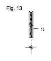
図11は、シャンク13と、シャンク10に半田付けされた切削ヘッド12と、形状的結合によりシャンク13に取り付けられたクランプスリーブ14と、被覆および半田付けによってシャンク13をリテーナーリング15に固定するクランプスリーブ14とからなる深穴ドリル10の未加工鋳造品の側面図を示す。シャンク11、クランプスリーブ14およびリテーナーリング15は、図12~図15により詳細に示されている。切削ヘッド11の未加工鋳造品は、図16により詳細に示されている。図11、図12および図16に示すように、シャンク11および切削ヘッド12は、それぞれ、直線溝を有するように設計されている。
FIG. 11 shows a
切削ヘッド12をシャンク13に接続するために、シャンク13は、切削ヘッド側の端末に、はんだ付けプリズム(Loetprisma)と称されるV字形のノッチ16を有し、このノッチ16内に、形状的結合により、切削ヘッド12のシャンク側の端末に形成されたウェッジ先端17が収容され、シャンク13にはんだ付けすることにより材料的に結合される。
In order to connect the cutting
図12および図13の平面図が示すように、シャンク13は、90°の角度距離で配置された4つのウェブ22を18に有し、各ウェブ22の間には、1つの、回転軸1に平行に延びる切屑排出溝19が形成されている。
As the plan views of FIGS. 12 and 13 show, the
図15に示すクランプスリーブ14は、切屑排出溝19の数に対応して、4つの軸方向の、略四分円のセグメントの形状の突起21を有し、当該突起21は、シャンク13をクランプスリーブ14に連結するために、それぞれ切屑排出溝19の1つに形状的結合により挿入される。参照符号14aは、クランプ面を示し、これを介してクランプスリーブ14が(図示されていない)チャックに回転不能に固定されうる。
The clamping
図14に示すリテーナーリング15は、このようにしてクランプスリーブ14とシャンク13との間に形成された界面上に位置する。シャンク13をクランプスリーブ14に固定するために、リテーナーリング15はシャンク13およびクランプスリーブ14にはんだ付けされる。
The
切削ヘッド12は、図16に示す切削ヘッドの未加工鋳造品24から作りだされる。V字状の破線は、シャンク16のV字状ノッチに接続される、切削ヘッド12のウェッジ先端17を示す。シャンク13と同様に、切削ヘッド12は、90°の角度距離で配置された4つのウェブ22を有し、各ウェブ22の間には、回転軸1に平行して直線的に延びる、実質的にV字形の切屑排出溝23が形成されている(これに関して図16の平面図を参照)。
The cutting
シャンク13に取り付けられた状態(図11参照)では、シャンクの切屑排出溝19が、切削ヘッド12の切屑排出溝23に軸方向に接続する。図11に見られるように、切削ヘッド12は、シャンク13よりも少し大きい直径を有する。
When mounted on the shank 13 (see FIG. 11), the chip flutes 19 of the shank axially connect to the chip flutes 23 of the cutting
図12および図16には、クランプスリーブ14およびシャンク13を通って切削ヘッド12まで延在する中央主チャンネル25と、ウェブ22または切屑排出溝23の数に対応して4つの分岐チャンネル26とから成る内部冷却潤滑剤供給システムが破線で示されており、当該4つの分岐チャンネル26は、シャンク13と切削ヘッド12との接合直後に主チャンネル25から分岐し、切削ヘッド12の後述する4つの主切れ刃の逃げ面の領域に位置する流出口27を有する。主チャンネル25および分岐チャンネル26は、それぞれ直線的に延びている(穴あけ)。
12 and 16 from a central
図1~図10は、図1に示す状態で切削ヘッド12の前面側の端末において行われる、4枚刃切削ヘッド12のドリル先端11の先端研削を示す。したがって、図1~図10は、切削ヘッド12のドリル先端11を研削加工のための研削マニュアルに相当する。
1-10 illustrate the tip grinding of the
図1は、ドリル先端11に4つの主切れ刃33(ウェブ22当たり1つの主切れ刃33)が形成されていることを示している。図示の実施例では、上記4つの主切れ刃33は、それぞれ外周切れ刃コーナー31cからドリル先端11の中心にあるチゼルエッジ34(図7参照)まで延在する、回転軸1に対して点対称的に配置された2つのより長いまたは(以下:)長い主切れ刃33と、それぞれ外周切れ刃コーナー30cからドリル先端11の中心までではないが、ドリル先端の方向に延在する、回転軸11に対して点対称的に配置された2つのより短いまたは(以下:)短い主切れ刃30とを含む。各長い主切れ刃33は、本発明によれば、切れ刃コーナー31cからステップまたは(以下:)段31d(図2参照)まで延在する外側部分切れ刃31と、上記段31dからチゼルエッジ34まで延在する内側部分切れ刃32とを有する。
FIG. 1 shows that the
内側部分切れ刃32は、深穴ドリル10の軸方向または送り方向に見て、外側部分切れ刃31および上記2つの短い主切れ刃30よりも大きな切れ刃高さを有する。したがって、より高く位置する内側部分切れ刃32は、パイロット穴切れ刃またはパイロット穴不要切れ刃とも称され、これらを介してドリルはパイロット穴がないものに切削することができ、他方では、外側部分切れ刃31および短い主切れ刃30は、カウンターボア切れ刃とも称され、これを介して、内側部分切れ刃32によって生成された穴が、深穴ドリルの公称直径まで中刳りされる。
The inner
より高く位置する内側部分切れ刃32は深穴ドリル10のコア35の領域にあり、他方では、外側部分切れ刃31および上記2つの短い主切れ刃30はコア35の外側にある。したがって、外側部分切れ刃31および短い主切れ刃30は、コア35の半径方向外側で終わるか、または、外側から内側に見て、コア35の前方で終わる。図示の実施例では、コア35の直径は、深穴ドリルの公称直径の約0.4~0.6倍、特に約0.5倍である。
The higher inner
上記段31dによって達成される、内側部分切れ刃32と外側部分切れ刃31との切れ刃高さ差Δxは、深穴ドリル10の公称直径の0.02~0.1倍、特に0.04~0.08倍の範囲にある。図2から分かるように、段31dは軸方向にレリーフ研磨されている。∈で示される角度は、例えば90°である。
The cutting edge height difference Δx between the inner
各切れ刃31c、30cには、ここではより詳細には説明されていない、直線的に延びる二次切れ刃が通常の方法で隣接している。
Each
図1~図10は、外側部分切れ刃31、内側部分切れ刃32および短い主切れ刃30がそれぞれ直線的に形成されていることを示している。
1 to 10 show that the outer
さらに、外側部分切れ刃31、内側部分切れ刃32および短い主切れ刃30は、同じ先端角度で配置されている。図2および図8にδ31、δ32、δ30で示される、外側部分切れ刃31、内側部分切れ刃32および短い主切れ刃30の先端角度は、実施例では、140°~150°の範囲内、特に145°である。
Furthermore, the outer
さらに、2つの内側部分切れ刃32は、同じ切れ刃高さに配置されている。さらに、外側部分切れ刃31同士は、同じ切れ刃高さで配置され、短い主切れ刃30同士は、同じ切れ刃高さで配置されている。しかしながら、図示の実施例では、短い主切れ刃30は、外側部分切れ刃31と比較して、0.01~0.03mmの範囲内、特に0.02mmであることができる、所定の切れ刃高さ差を有する。
Furthermore, the two inner
さらに、内側部分切れ刃32、外側部分切れ刃31および短い主切れ刃30は、切削方向に見て、深穴ドリル10の直径面の前方に位置し、すなわち「中央の前に」切削する。
Furthermore, the inner
全ての主切れ刃、すなわち内側部分切れ刃32、外側部分切れ刃31および短い主切れ刃30の図示しないすくい角は、図示の実施例では0°以上である。
The rake angle, not shown, of all the main cutting edges, namely the inner
図7では、外側部分切れ刃32、内側部分切れ刃32および短い主切れ刃30に関して、参照符号31a、32a、30aで一次逃げ面、参照符号31b、32b、30bで二次逃げ面が示されている。
In FIG. 7, for the outer
図7は、さらに、上述の内部冷却潤滑剤供給システムの4つの分岐チャンネル26の各流出口27が、割り当てられた主切れ刃逃げ面の領域、特に二次逃げ面の領域に位置することを示す。
FIG. 7 further shows that each
図1~図10には、研削されたシンニング40、41、42が見られ、これらによりチゼルエッジ34の短縮(図7参照)、内側部分切れ刃32の矯正、または、切削方向または回転方向に短い主切れ刃30の前方にあるコア領域の矯正が達成される。図1または図7では、ドリル先端11にシンニング面が明瞭に見える。シンニング40によってチゼルエッジ34の短縮が達成される。シンニング41は、内側部分切れ刃32を矯正するので、図示の実施例において内側部分切れ刃32は、同じ主切れ刃の外側切れ刃32に対してある角度で延びる。シンニング42によって、回転方向または切削方向に短い主切れ刃30の前方に位置するコア領域が研削される。
1 to 10 can be seen
上記シンニングは、(図示されていない)特殊な研磨盤を用いて研削される。したがって、各シンニングの断面輪郭は、それぞれの使用される研磨盤の形状によって決定される。図3~図6、図9および図10は、上記研削を説明するものであり、図5、図6および図10は、研削が紙面に垂直な方向に延びる位置および方向づけにおける深穴ドリル10を示し、図3、図4および図9は、深穴ドリル10の回転軸11に垂直な面に対する、研削の傾斜角α40、α41、α42を示す。
The thinning is ground using a special grinder (not shown). Therefore, the cross-sectional profile of each thinning is determined by the shape of the respective grinder used. 3-6, 9 and 10 illustrate the grinding described above, and FIGS. 5, 6 and 10 show the
図3および図5は、特に、チゼルエッジ34を短縮するシンニング40を生成するための研削を示し、図4および図6は、内側部分切れ刃31を矯正するシンニング41を生成するための研削を示し、図9および図10は、シンニング42を生成するための研削を示す。研削またはシンニング40、41、42の断面輪郭、したがって、それぞれの場合に使用される研磨盤の形状は、図5、図6、図10に見られる。
Figures 3 and 5 show in particular grinding to produce a thinning 40 for shortening the
図5、図6および図10は、それぞれ深穴ドリル10の割り当てられた切屑排出溝23で終わるシンニング40、41および42が、開口角度がβ40またはβ41である丸めた基部を有する略V字状の断面を有するか(図5、図6参照)、または、浅い窪地の形をしている断面を有する(図10参照)ことを示す。図示の実施例において、上記開口角β40またはβ41は、75°~85°の範囲内、例えば80°である。
Figures 5, 6 and 10 show that the
深穴ドリル10の回転軸11に垂直な面に対する上述の傾斜角α40、α41、α42は、図示の実施例では、30°と50°との間であり、傾斜角α40は例えば35°であり、傾斜角α41は例えば40°であり、傾斜角α42は例えば48°であることができる。
The above-mentioned angles of inclination α 40 , α 41 , α 42 with respect to the plane perpendicular to the axis of
もちろん、本発明のドリルは、上述した実施例に比べて変形されていることができる。 Of course, the drill of the invention can be modified compared to the embodiments described above.
例えば、図1~図10を参照して説明された先端研削は、基本的に任意の長さのドリルに用いることができる。したがって、本発明のドリルは、必ずしも深穴ドリルに限定されない。 For example, the point grinding described with reference to FIGS. 1-10 can be used on drills of essentially any length. Accordingly, the drill of the present invention is not necessarily limited to deep hole drills.
説明した実施例とは異なる点として、本発明のドリル、例えば深穴ドリルは、さらに、一体から作られ、すなわち、モノリシックに形成されていることができる。 As a departure from the exemplary embodiment described, the drill according to the invention, for example a deep-hole drill, can also be made in one piece, ie of monolithic design.
さらに、本発明によるドリル、例えば深穴ドリルは、螺旋状の溝を有するように設計することができる。 Furthermore, a drill according to the invention, eg a deep hole drill, can be designed with a helical flute.
説明した実施例とは異なる点として、ウェブ22(すなわち、切屑排出溝23または主切れ刃30、33)は、90°の角度距離で配置することができる。その場合に、直径方向に対向する主切れ刃33または30は、点対称的に配置することができる。 As a departure from the described embodiment, the webs 22 (ie chip flutes 23 or main cutting edges 30, 33) can be arranged at an angular distance of 90°. The diametrically opposed main cutting edges 33 or 30 can then be arranged symmetrically.
本出願において、後の出願において、分割出願または実用新案分岐出願(Gebrauchsmusterabzweigung)のいずれかによって、後の時点で保護を請求することができる、請求項1に記載された特徴の組合せから独立した対象は、最も単純な場合には、直線溝付き4枚刃ドリル、特に深穴ドリルである。
Subject matter independent of the combination of features recited in
したがって、独立した主請求項は、4つの主切れ刃を備えたドリル先端を有する直線溝付きドリル、特に深穴ドリルを目指すことができる。このようなドリル、特に深穴ドリルは、初めに述べたUS 5,173,014と異なって、より簡単かつ低コストに製造できる。この主請求項の後には、本出願の請求項、明細書および/または図面から生じる、4枚刃ドリルのさらなる設計特徴に関連する従属請求項が続くことができる。 A separate main claim can therefore be directed to a straight fluted drill, in particular a deep hole drill, having a drill tip with four main cutting edges. Such drills, in particular deep-hole drills, are simpler and less costly to manufacture, unlike US Pat. No. 5,173,014, mentioned at the outset. This main claim may be followed by dependent claims relating to further design features of the four-flute drill, arising from the claims, the description and/or the drawings of the present application.
一従属請求項の対象は、例えば、ドリルの4つの主切れ刃が、それぞれ外周切れ刃コーナーからドリル先端の中心にあるチゼルエッジまで延びる、回転軸に対して点対称的に配置された2つの長い主切れ刃と、それぞれ外周切れ刃コーナーからドリル先端の中心の方向に延びる、回転軸に対して点対称的に配置された2つの短い主切れ刃とを含むことである。 The subject of a dependent claim is, for example, that the four main cutting edges of the drill each extend from a peripheral cutting edge corner to a chisel edge in the center of the drill point, two long, point-symmetrically arranged with respect to the axis of rotation. It comprises a main cutting edge and two short main cutting edges arranged symmetrically with respect to the axis of rotation, each extending from the peripheral cutting edge corner in the direction of the center of the drill tip.
さらなる一従属請求項の対象は、ドリルの4つの主切れ刃がコアにおいて軸方向に段で分離された先端を定義することであり得る。この先端は、例えば、各長い主切れ刃が、切れ刃コーナーから上記段まで延びる外側部分切れ刃と、上記段からチゼルエッジまで延び、外側部分切れ刃および短い主切れ刃よりも高い切れ刃高さを有する内側部分切れ刃とを有することで達成することができる。 The subject of a further dependent claim may be that the four main cutting edges of the drill define tips that are axially separated by a step at the core. This tip may, for example, have an outer partial cutting edge where each long main cutting edge extends from the cutting edge corner to the step and from the step to the chisel edge and has a higher cutting edge height than the outer partial cutting edge and the short main cutting edge. can be achieved by having an inner partial cutting edge with
さらなる従属請求項の対象は、回転方向または切削方向にそれぞれの主切れ刃の後方に逃げ面の領域に位置する、冷却潤滑剤のための流出口がそれぞれの上記4つの主切れ刃に割り当てられていることであり得る。 The subject of a further dependent claim is that each of said four main cutting edges is assigned an outlet for cooling lubricant, which is located behind the respective main cutting edge in the direction of rotation or in the region of the flank. It can be that
Claims (18)
各長い主切れ刃(33)は、切れ刃コーナー(31c)から段(31d)まで延在する外側部分切れ刃(31)と、外側部分切れ刃(31)および短い主切れ刃(30)よりも大きい切れ刃高さ(Δx)を有する、前記段(31d)からチゼルエッジ(34)まで延在する内側部分切れ刃(32)とを有し、
前記外側部分切れ刃(31)と前記内側部分切れ刃(32)とは、同じ先端角(δ31、δ32)を有し、
段によって達成される、長い主切れ刃(33)の内側部分切れ刃(32)と外側部分切れ刃(31)との間の切れ刃高さの差は、ドリルの公称直径の0.02~0.1倍の範囲にあることを特徴とする4枚刃ドリル(10)。 Two long main cutting edges (33) arranged symmetrically with respect to the axis of rotation (11), each extending from a peripheral cutting edge corner (31c) to a chisel edge (34) in the center of the drill tip (11). ) and two short main cutting edges (30) arranged symmetrically with respect to the axis of rotation (11), each extending from the peripheral cutting edge corner (30c) towards the center of the drill tip (11). A four-flute drill (10) comprising:
Each long major cutting edge (33) has an outer partial cutting edge (31) extending from a cutting edge corner (31c) to a step (31d) and a an inner partial cutting edge (32) extending from said step (31d) to a chisel edge (34) having a greater cutting edge height (Δx);
The outer partial cutting edge (31) and the inner partial cutting edge (32) have the same tip angle (δ 31 , δ 32 ),
The difference in cutting edge height between the inner part cutting edge (32) and the outer part cutting edge (31) of the long main cutting edge (33) achieved by the step is 0.02 to 0.02 mm of the nominal diameter of the drill. A four-flute drill (10) characterized by a range of 0.1.
Applications Claiming Priority (3)
| Application Number | Priority Date | Filing Date | Title |
|---|---|---|---|
| DE102017216393.3A DE102017216393A1 (en) | 2017-09-15 | 2017-09-15 | LOW-DRILLING DRILL |
| DE102017216393.3 | 2017-09-15 | ||
| PCT/EP2018/073886 WO2019052876A1 (en) | 2017-09-15 | 2018-09-05 | Four-edged drill |
Publications (2)
| Publication Number | Publication Date |
|---|---|
| JP2020533191A JP2020533191A (en) | 2020-11-19 |
| JP7304340B2 true JP7304340B2 (en) | 2023-07-06 |
Family
ID=63586668
Family Applications (1)
| Application Number | Title | Priority Date | Filing Date |
|---|---|---|---|
| JP2020514751A Active JP7304340B2 (en) | 2017-09-15 | 2018-09-05 | 4-flute drill |
Country Status (9)
| Country | Link |
|---|---|
| US (1) | US11161182B2 (en) |
| EP (1) | EP3681660B1 (en) |
| JP (1) | JP7304340B2 (en) |
| KR (1) | KR102554321B1 (en) |
| CN (1) | CN111201102B (en) |
| CA (1) | CA3075776C (en) |
| DE (1) | DE102017216393A1 (en) |
| MX (1) | MX2020002805A (en) |
| WO (1) | WO2019052876A1 (en) |
Families Citing this family (4)
| Publication number | Priority date | Publication date | Assignee | Title |
|---|---|---|---|---|
| TWD210418S (en) * | 2020-05-28 | 2021-03-11 | 鴻安國際興業有限公司 | Part of the chamfering rotary knife |
| USD1009108S1 (en) | 2020-09-21 | 2023-12-26 | Kyocera Unimerco Tooling A/S | Drill |
| KR102582433B1 (en) * | 2021-10-25 | 2023-09-27 | 한국생산기술연구원 | Cutting tool having a cooling path inside the tool |
| KR102548877B1 (en) | 2022-05-20 | 2023-06-27 | 이종화 | 6-blade drill |
Citations (8)
| Publication number | Priority date | Publication date | Assignee | Title |
|---|---|---|---|---|
| JP2003039218A (en) | 2001-07-24 | 2003-02-12 | Nachi Fujikoshi Corp | Drill for deep hole |
| JP2005205526A (en) | 2004-01-22 | 2005-08-04 | Nachi Fujikoshi Corp | Deep hole boring tool |
| JP2007503322A (en) | 2003-05-20 | 2007-02-22 | サンドビック インテレクチュアル プロパティー アクティエボラーグ | Drill body having cutting edge, manufacturing method thereof, and drilling tool including the drill body |
| JP2010214478A (en) | 2009-03-13 | 2010-09-30 | Fuji Heavy Ind Ltd | Drill |
| CN102581355A (en) | 2012-03-27 | 2012-07-18 | 周安善 | Twist drill for drilling precision holes on high-strength and high-hardness alloy materials |
| JP2013000843A (en) | 2011-06-17 | 2013-01-07 | Makotoroi Kogyo Kk | Drill |
| US20160001379A1 (en) | 2014-07-01 | 2016-01-07 | Kennametal Inc. | Drill head |
| US20170021433A1 (en) | 2015-07-23 | 2017-01-26 | The Boeing Company | Bottom cutting step up reamer |
Family Cites Families (29)
| Publication number | Priority date | Publication date | Assignee | Title |
|---|---|---|---|---|
| US327148A (en) * | 1885-09-29 | Metal-boring bit | ||
| US1000067A (en) * | 1911-03-16 | 1911-08-08 | Paul C Seegmueller | Drill. |
| GB540073A (en) * | 1940-07-22 | 1941-10-03 | Ferranti Ltd | Improvements in or relating to metal drills |
| DE1031951B (en) * | 1953-11-13 | 1958-06-12 | Alfred Kunkel | Masonry drill |
| JPS4991895U (en) * | 1972-11-28 | 1974-08-08 | ||
| US4137002A (en) * | 1977-12-05 | 1979-01-30 | General Motors Corporation | High speed coolant feeding gun drill and cutting head section therefor |
| JPH0533202Y2 (en) * | 1986-01-10 | 1993-08-24 | ||
| DE3707798A1 (en) * | 1987-03-11 | 1988-09-22 | Hawera Probst Kg Hartmetall | ROCK DRILL |
| JPH0297510U (en) * | 1989-01-24 | 1990-08-03 | ||
| JPH0435812U (en) * | 1990-07-17 | 1992-03-25 | ||
| US5173014A (en) | 1992-02-07 | 1992-12-22 | General Motors Corporation | Four flute center cutting drill |
| JPH1094949A (en) * | 1996-09-25 | 1998-04-14 | Riken Seiko Kk | Drill grinding device |
| SE517946C2 (en) * | 1999-07-14 | 2002-08-06 | Seco Tools Ab | Drilling unit with three inserts and cooling duct |
| DE10009732A1 (en) * | 2000-03-02 | 2001-09-06 | Hawera Probst Gmbh | Rock drill has drill head, spiral conveyor with main and subsidiary webs, conveyor edges, main and subsidiary cutter-blades. |
| DE10024433A1 (en) * | 2000-05-19 | 2001-11-29 | Hawera Probst Gmbh | Rock drill |
| DE10053344A1 (en) * | 2000-10-27 | 2002-05-08 | Hilti Ag | rock drill |
| EP1302290B1 (en) * | 2001-10-12 | 2008-07-02 | Robert Bosch Gmbh | Drilling tool |
| WO2005049295A1 (en) * | 2003-11-17 | 2005-06-02 | Robert Bosch Gmbh | Drilling and/or chiselling tool |
| DE102004028098A1 (en) * | 2004-06-09 | 2005-12-29 | Hilti Ag | drill |
| DE202007014367U1 (en) * | 2007-10-12 | 2008-01-03 | Keil Werkzeugfabrik Karl Eischeid Gmbh | drill |
| US7861807B2 (en) * | 2008-12-03 | 2011-01-04 | Black & Decker Inc. | Drill bit including one piece cutting head |
| DE102008054869B4 (en) * | 2008-12-18 | 2010-09-02 | Hilti Aktiengesellschaft | Drilling head for rock drills |
| DE102009024256A1 (en) * | 2009-06-05 | 2010-12-09 | Botek Präzisionsbohrtechnik Gmbh | Deep hole drill has cutter that is formed at drill head, where cutter has cutter edge, where cutter edge is assigned to chip breaker for breaking chips removed by cutter edge |
| DE102009031193A1 (en) * | 2009-06-29 | 2010-12-30 | Botek Präzisionsbohrtechnik Gmbh | Deep-hole drill for inserting boreholes into work-pieces, has blade partitioned into partial cuts by chip divider, where cuts of blade are arranged together such that cut-normals are aligned to each other by cuts at angle of twenty degrees |
| DE202011100380U1 (en) * | 2011-05-06 | 2012-08-07 | Illinois Tool Works Inc. | rock drill |
| CN103084629A (en) * | 2013-02-01 | 2013-05-08 | 周安善 | Twist drill with segmented main cutting blades and asymmetric blade opening height |
| JP6606840B2 (en) * | 2014-03-28 | 2019-11-20 | 三菱マテリアル株式会社 | Rotary cutting tool with polycrystalline diamond sintered body |
| ES2660842T3 (en) * | 2015-03-23 | 2018-03-26 | Walter Ag | Drill Bit |
| JP6447566B2 (en) * | 2015-04-24 | 2019-01-09 | 株式会社タンガロイ | Drilling tool |
-
2017
- 2017-09-15 DE DE102017216393.3A patent/DE102017216393A1/en active Pending
-
2018
- 2018-09-05 JP JP2020514751A patent/JP7304340B2/en active Active
- 2018-09-05 WO PCT/EP2018/073886 patent/WO2019052876A1/en unknown
- 2018-09-05 CA CA3075776A patent/CA3075776C/en active Active
- 2018-09-05 MX MX2020002805A patent/MX2020002805A/en unknown
- 2018-09-05 EP EP18769616.6A patent/EP3681660B1/en active Active
- 2018-09-05 KR KR1020207010299A patent/KR102554321B1/en active IP Right Grant
- 2018-09-05 CN CN201880059547.5A patent/CN111201102B/en active Active
-
2020
- 2020-03-11 US US16/815,452 patent/US11161182B2/en active Active
Patent Citations (8)
| Publication number | Priority date | Publication date | Assignee | Title |
|---|---|---|---|---|
| JP2003039218A (en) | 2001-07-24 | 2003-02-12 | Nachi Fujikoshi Corp | Drill for deep hole |
| JP2007503322A (en) | 2003-05-20 | 2007-02-22 | サンドビック インテレクチュアル プロパティー アクティエボラーグ | Drill body having cutting edge, manufacturing method thereof, and drilling tool including the drill body |
| JP2005205526A (en) | 2004-01-22 | 2005-08-04 | Nachi Fujikoshi Corp | Deep hole boring tool |
| JP2010214478A (en) | 2009-03-13 | 2010-09-30 | Fuji Heavy Ind Ltd | Drill |
| JP2013000843A (en) | 2011-06-17 | 2013-01-07 | Makotoroi Kogyo Kk | Drill |
| CN102581355A (en) | 2012-03-27 | 2012-07-18 | 周安善 | Twist drill for drilling precision holes on high-strength and high-hardness alloy materials |
| US20160001379A1 (en) | 2014-07-01 | 2016-01-07 | Kennametal Inc. | Drill head |
| US20170021433A1 (en) | 2015-07-23 | 2017-01-26 | The Boeing Company | Bottom cutting step up reamer |
Also Published As
| Publication number | Publication date |
|---|---|
| CN111201102B (en) | 2023-04-04 |
| MX2020002805A (en) | 2020-09-14 |
| US11161182B2 (en) | 2021-11-02 |
| CA3075776A1 (en) | 2019-03-21 |
| CA3075776C (en) | 2022-10-04 |
| WO2019052876A1 (en) | 2019-03-21 |
| JP2020533191A (en) | 2020-11-19 |
| EP3681660B1 (en) | 2024-05-01 |
| DE102017216393A1 (en) | 2019-03-21 |
| KR20200053544A (en) | 2020-05-18 |
| CN111201102A (en) | 2020-05-26 |
| EP3681660A1 (en) | 2020-07-22 |
| KR102554321B1 (en) | 2023-07-10 |
| US20200282473A1 (en) | 2020-09-10 |
Similar Documents
| Publication | Publication Date | Title |
|---|---|---|
| JP7304340B2 (en) | 4-flute drill | |
| EP0891239B1 (en) | Twist drill with asymmetrically spaced support margins | |
| JP5171827B2 (en) | How to use throwaway tips and throwaway tips | |
| JP5390527B2 (en) | Rotating tool | |
| CN102310216B (en) | Drilling tool | |
| CA2207418C (en) | Drilling tool with reset inserts | |
| JP5320390B2 (en) | Drill tool and drilling method | |
| US20110318128A1 (en) | Drill tip and drilling tool having a drill tip | |
| US20130315681A1 (en) | Rotary cutter | |
| US10183343B2 (en) | Drill bit for drilling laminates | |
| KR20070015621A (en) | Drill, particularly a spiral drill | |
| US20100158623A1 (en) | Drill body as well as support pad therefor | |
| JP5568306B2 (en) | Modular drilling tool and manufacturing method | |
| US10507533B2 (en) | Drill | |
| US20180297128A1 (en) | End mill | |
| US20230219147A1 (en) | Drill and method for producing a drill | |
| KR20110109831A (en) | Reamer | |
| US11607737B2 (en) | Milling tool | |
| JP2009184044A (en) | Stepped twist drill and method of manufacturing the same | |
| US11819931B2 (en) | Drill | |
| US11103933B2 (en) | Step drill and manufacturing method for step drill | |
| JP2009050994A (en) | Hole working tool | |
| JPH031134Y2 (en) | ||
| WO2008028491A9 (en) | A drilling tool, a method for drilling a hole and a use of a drilling tool | |
| JP2009241232A (en) | Reaming tool |
Legal Events
| Date | Code | Title | Description |
|---|---|---|---|
| A621 | Written request for application examination |
Free format text: JAPANESE INTERMEDIATE CODE: A621 Effective date: 20210811 |
|
| A977 | Report on retrieval |
Free format text: JAPANESE INTERMEDIATE CODE: A971007 Effective date: 20220624 |
|
| A131 | Notification of reasons for refusal |
Free format text: JAPANESE INTERMEDIATE CODE: A131 Effective date: 20220705 |
|
| A521 | Request for written amendment filed |
Free format text: JAPANESE INTERMEDIATE CODE: A523 Effective date: 20220930 |
|
| A131 | Notification of reasons for refusal |
Free format text: JAPANESE INTERMEDIATE CODE: A131 Effective date: 20230124 |
|
| A521 | Request for written amendment filed |
Free format text: JAPANESE INTERMEDIATE CODE: A523 Effective date: 20230202 |
|
| TRDD | Decision of grant or rejection written | ||
| A01 | Written decision to grant a patent or to grant a registration (utility model) |
Free format text: JAPANESE INTERMEDIATE CODE: A01 Effective date: 20230606 |
|
| A61 | First payment of annual fees (during grant procedure) |
Free format text: JAPANESE INTERMEDIATE CODE: A61 Effective date: 20230626 |
|
| R150 | Certificate of patent or registration of utility model |
Ref document number: 7304340 Country of ref document: JP Free format text: JAPANESE INTERMEDIATE CODE: R150 |