JP7303487B2 - Vehicle lighting device and vehicle lamp - Google Patents
Vehicle lighting device and vehicle lamp Download PDFInfo
- Publication number
- JP7303487B2 JP7303487B2 JP2019100327A JP2019100327A JP7303487B2 JP 7303487 B2 JP7303487 B2 JP 7303487B2 JP 2019100327 A JP2019100327 A JP 2019100327A JP 2019100327 A JP2019100327 A JP 2019100327A JP 7303487 B2 JP7303487 B2 JP 7303487B2
- Authority
- JP
- Japan
- Prior art keywords
- distance
- light
- mounting portion
- light extraction
- lighting device
- Prior art date
- Legal status (The legal status is an assumption and is not a legal conclusion. Google has not performed a legal analysis and makes no representation as to the accuracy of the status listed.)
- Active
Links
Images


Classifications
-
- F—MECHANICAL ENGINEERING; LIGHTING; HEATING; WEAPONS; BLASTING
- F21—LIGHTING
- F21S—NON-PORTABLE LIGHTING DEVICES; SYSTEMS THEREOF; VEHICLE LIGHTING DEVICES SPECIALLY ADAPTED FOR VEHICLE EXTERIORS
- F21S41/00—Illuminating devices specially adapted for vehicle exteriors, e.g. headlamps
- F21S41/10—Illuminating devices specially adapted for vehicle exteriors, e.g. headlamps characterised by the light source
- F21S41/19—Attachment of light sources or lamp holders
- F21S41/194—Bayonet attachments
-
- F—MECHANICAL ENGINEERING; LIGHTING; HEATING; WEAPONS; BLASTING
- F21—LIGHTING
- F21V—FUNCTIONAL FEATURES OR DETAILS OF LIGHTING DEVICES OR SYSTEMS THEREOF; STRUCTURAL COMBINATIONS OF LIGHTING DEVICES WITH OTHER ARTICLES, NOT OTHERWISE PROVIDED FOR
- F21V19/00—Fastening of light sources or lamp holders
- F21V19/001—Fastening of light sources or lamp holders the light sources being semiconductors devices, e.g. LEDs
- F21V19/003—Fastening of light source holders, e.g. of circuit boards or substrates holding light sources
-
- F—MECHANICAL ENGINEERING; LIGHTING; HEATING; WEAPONS; BLASTING
- F21—LIGHTING
- F21S—NON-PORTABLE LIGHTING DEVICES; SYSTEMS THEREOF; VEHICLE LIGHTING DEVICES SPECIALLY ADAPTED FOR VEHICLE EXTERIORS
- F21S41/00—Illuminating devices specially adapted for vehicle exteriors, e.g. headlamps
- F21S41/10—Illuminating devices specially adapted for vehicle exteriors, e.g. headlamps characterised by the light source
- F21S41/19—Attachment of light sources or lamp holders
- F21S41/192—Details of lamp holders, terminals or connectors
-
- F—MECHANICAL ENGINEERING; LIGHTING; HEATING; WEAPONS; BLASTING
- F21—LIGHTING
- F21S—NON-PORTABLE LIGHTING DEVICES; SYSTEMS THEREOF; VEHICLE LIGHTING DEVICES SPECIALLY ADAPTED FOR VEHICLE EXTERIORS
- F21S41/00—Illuminating devices specially adapted for vehicle exteriors, e.g. headlamps
- F21S41/20—Illuminating devices specially adapted for vehicle exteriors, e.g. headlamps characterised by refractors, transparent cover plates, light guides or filters
- F21S41/25—Projection lenses
-
- F—MECHANICAL ENGINEERING; LIGHTING; HEATING; WEAPONS; BLASTING
- F21—LIGHTING
- F21S—NON-PORTABLE LIGHTING DEVICES; SYSTEMS THEREOF; VEHICLE LIGHTING DEVICES SPECIALLY ADAPTED FOR VEHICLE EXTERIORS
- F21S41/00—Illuminating devices specially adapted for vehicle exteriors, e.g. headlamps
- F21S41/10—Illuminating devices specially adapted for vehicle exteriors, e.g. headlamps characterised by the light source
- F21S41/14—Illuminating devices specially adapted for vehicle exteriors, e.g. headlamps characterised by the light source characterised by the type of light source
- F21S41/141—Light emitting diodes [LED]
- F21S41/143—Light emitting diodes [LED] the main emission direction of the LED being parallel to the optical axis of the illuminating device
Landscapes
- Engineering & Computer Science (AREA)
- General Engineering & Computer Science (AREA)
- Fastening Of Light Sources Or Lamp Holders (AREA)
- Non-Portable Lighting Devices Or Systems Thereof (AREA)
Description
本発明の実施形態は、車両用照明装置、および車両用灯具に関する。 TECHNICAL FIELD Embodiments of the present invention relate to a vehicle lighting device and a vehicle lamp.
ソケットと、ソケットの一方の端部側に設けられた発光モジュールと、を備えた車両用照明装置がある。発光モジュールには、基板が設けられ、基板の一方の面には発光素子や抵抗などが設けられている。この様な車両用照明装置においては、発光モジュールは、ソケットの端面に開口する凹部の内部に設けられる。そのため、発光モジュールが凹部の内壁面に囲まれることになり、発光素子から出射した光の一部が凹部の内壁面に入射する。凹部の内壁面に入射した光の一部は内壁面に吸収されるので、その分、光の取り出し効率が低下することになる。 BACKGROUND ART There is a vehicle lighting device that includes a socket and a light-emitting module provided on one end side of the socket. A light-emitting module is provided with a substrate, and a light-emitting element, a resistor, and the like are provided on one surface of the substrate. In such a vehicle lighting device, the light-emitting module is provided inside a recess opening in the end face of the socket. Therefore, the light emitting module is surrounded by the inner wall surface of the recess, and part of the light emitted from the light emitting element enters the inner wall surface of the recess. A part of the light incident on the inner wall surface of the recess is absorbed by the inner wall surface, so that the light extraction efficiency is reduced accordingly.
ここで、凹部の内壁面にスリットを設け、スリットの内部に基板の角部を収納する技術が提案されている。スリットが設けられた部分には凹部の内壁面がないので、この部分に照射された光は内壁面に吸収されることがない。しかしながら、スリットは基板の位置決めを行うものであるため幅寸法を小さくする必要がある。そのため、凹部の内壁面に設けられたスリットでは、光の取り出し効率を向上させることができない。
そこで、光の取り出し効率を向上させることができる技術の開発が望まれていた。
Here, a technique has been proposed in which a slit is provided in the inner wall surface of the recess and the corner of the substrate is accommodated inside the slit. Since there is no inner wall surface of the recess in the portion where the slit is provided, the light irradiated to this portion is not absorbed by the inner wall surface. However, since the slit is for positioning the substrate, it is necessary to reduce the width dimension. Therefore, the slit provided on the inner wall surface of the recess cannot improve the light extraction efficiency.
Therefore, it has been desired to develop a technique capable of improving the light extraction efficiency.
本発明が解決しようとする課題は、光の取り出し効率を向上させることができる車両用照明装置、および車両用灯具を提供することである。 The problem to be solved by the present invention is to provide a vehicle lighting device and a vehicle lamp capable of improving light extraction efficiency.
実施形態に係る車両用照明装置は、一方の端面に開口する第1の凹部を有する装着部と;基板と、前記基板に設けられた少なくとも1つの発光素子と、前記発光素子を覆う封止部と、を有し、前記第1の凹部の内部に設けられた発光モジュールと;前記装着部の外側面に設けられた複数のバヨネットと;を具備している。前記装着部は、前記第1の凹部の内壁面と前記装着部の外側面との間を貫通する少なくとも1つの光取り出し部を有している。前記光取り出し部は、前記装着部の、前記第1の凹部が開口する端面に開口する第2の凹部、前記装着部の周方向に延びる貫通孔、および、前記装着部の周方向に互いに隣接させて並べて設けられた複数の貫通孔の少なくともいずれかである。前記装着部の周方向の、前記バヨネットが設けられた部分において、前記第1の凹部の底面と、前記光取り出し部の前記底面側の端部と、の間の距離は、前記底面と、前記封止部の頂部と、の間の距離よりも小さい。前記装着部の周方向の、前記バヨネットが設けられていない部分において、前記底面と、前記装着部の、前記第1の凹部が開口する端面と、の間の距離は、前記底面と、前記封止部の頂部と、の間の距離よりも大きい。 A vehicle lighting device according to an embodiment includes a mounting portion having a first recess opening on one end face; a substrate; at least one light emitting element provided on the substrate; and a sealing portion covering the light emitting element. and a light-emitting module provided inside the first recess; and a plurality of bayonet provided on the outer surface of the mounting portion. The mounting portion has at least one light extraction portion penetrating between the inner wall surface of the first recess and the outer side surface of the mounting portion. The light extraction portion includes a second recess opening in an end face of the mounting portion where the first recess opens, a through hole extending in the circumferential direction of the mounting portion, and adjacent to each other in the circumferential direction of the mounting portion. At least one of a plurality of through holes arranged side by side. The distance between the bottom surface of the first concave portion and the end portion of the light extraction portion on the bottom surface side in the portion provided with the bayonet in the circumferential direction of the mounting portion is equal to the distance between the bottom surface and the smaller than the distance between the top of the seal and In a circumferential portion of the mounting portion where the bayonet is not provided, the distance between the bottom surface and the end surface of the mounting portion where the first recess opens is equal to the distance between the bottom surface and the seal. greater than the distance between the top of the stop and
本発明の実施形態によれば、光の取り出し効率を向上させることができる車両用照明装置、および車両用灯具を提供することができる。 According to the embodiments of the present invention, it is possible to provide a vehicle lighting device and a vehicle lamp capable of improving light extraction efficiency.
以下、図面を参照しつつ、実施の形態について例示をする。なお、各図面中、同様の構成要素には同一の符号を付して詳細な説明は適宜省略する。 Hereinafter, embodiments will be illustrated with reference to the drawings. In addition, in each drawing, the same reference numerals are given to the same constituent elements, and detailed description thereof will be omitted as appropriate.
(車両用照明装置)
本実施の形態に係る車両用照明装置1は、例えば、自動車や鉄道車両などに設けることができる。自動車に設けられる車両用照明装置1としては、例えば、フロントコンビネーションライト(例えば、デイタイムランニングランプ(DRL:Daytime Running Lamp)、ポジションランプ、ターンシグナルランプなどが適宜組み合わされたもの)や、リアコンビネーションライト(例えば、ストップランプ、テールランプ、ターンシグナルランプ、バックランプ、フォグランプなどが適宜組み合わされたもの)などに用いられるものを例示することができる。ただし、車両用照明装置1の用途は、これらに限定されるわけではない。
(Vehicle lighting device)
The
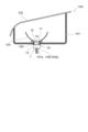
図1は、本実施の形態に係る車両用照明装置1を例示するための模式斜視図である。
図2は、図1における車両用照明装置1のA-A線断面図である。
図1および図2に示すように、車両用照明装置1には、ソケット10、発光モジュール20、および給電端子30を設けることができる。
FIG. 1 is a schematic perspective view for illustrating a
FIG. 2 is a cross-sectional view of the
As shown in FIGS. 1 and 2 , the
ソケット10には、装着部11、バヨネット12、フランジ13、放熱フィン14、およびコネクタホルダ15を設けることができる。
装着部11は、フランジ13の一方の面に設けることができる。装着部11の外形形状は、柱状とすることができる。装着部11の外形形状は、例えば、円柱状とすることができる。装着部11は、フランジ13側とは反対側の端面に開口する凹部11aを有することができる。
The
The
装着部11には、光取り出し部11bを設けることができる。光取り出し部11bは、凹部11aの内壁面と装着部11の外側面11cとの間を貫通するものとすることができる。また、光取り出し部11bは、装着部11の、フランジ13側とは反対側の端面に開口することができる。
The
光取り出し部11bは、少なくとも1つ設けることができる。ただし、複数の光取り出し部11bが設けられていれば、光の取り出し効率を向上させることが容易となる。光取り出し部11bは、例えば、複数のバヨネット12毎に設けることができる。すなわち、光取り出し部11bは、装着部11の周方向において、バヨネット12が設けられた領域に設けることができる。図1に例示をした装着部11には、4つの光取り出し部11b、すなわち、光取り出し部11b1、11b2、11b3、11b4が設けられている。
なお、光取り出し部11bに関する詳細は後述する。
At least one
Details of the
また、装着部11には、少なくとも1つのスリット11eを設けることができる。スリット11eの内部には、基板21の角部を設けることができる。装着部11の周方向におけるスリット11eの寸法(幅)は、基板21の角部の寸法よりも僅かに大きくすることができる。この様にすれば、スリット11eの内部に基板21の角部を挿入することで、基板21の位置決めを行うことができる。
Also, the
また、スリット11eを設けるようにすれば、基板21の平面形状を大きくすることができる。そのため、基板21上に実装する素子の数を増加させることができる。あるいは、装着部11の外形寸法を小さくすることができるので、装着部11の小型化、ひいては車両用照明装置1の小型化を図ることができる。
Further, by providing the
装着部11を装着部11の中心軸11dに沿った方向から見た場合に、複数のバヨネット12は、所定の間隔をあけて設けることができる。バヨネット12は、装着部11の外側面11cに複数設けることができる。複数のバヨネット12は、車両用照明装置1の外側に向けて突出させることができる。複数のバヨネット12は、フランジ13と対峙させることができる。複数のバヨネット12は、車両用照明装置1を車両用灯具100の筐体101に取り付ける際に用いることができる。複数のバヨネット12は、ツイストロックに用いることができる。
When the
フランジ13は、板状を呈するものとすることができる。例えば、フランジ13は、円板状を呈するものとすることができる。フランジ13の外側面は、バヨネット12の外側面よりも車両用照明装置1の外方に位置することができる。
The
放熱フィン14は、フランジ13の、装着部11側とは反対側に設けることができる。放熱フィン14は、少なくとも1つ設けることができる。例えば、図1および図2に例示をしたソケット10には複数の放熱フィン14が設けられている。複数の放熱フィン14は、所定の方向に並べて設けることができる。放熱フィン14は、板状を呈するものとすることができる。
The
コネクタホルダ15は、フランジ13の、装着部11が設けられる側とは反対側に設けることができる。コネクタホルダ15は筒状を呈するものとすることができる。シール部材105aを有するコネクタ105は、コネクタホルダ15の内部に挿入される。そのため、コネクタホルダ15の孔の断面形状は、シール部材105aを有するコネクタ105の断面形状に適合したものとすることができる。
The
発光モジュール20において発生した熱は、主に、装着部11およびフランジ13を介して放熱フィン14に伝わる。放熱フィン14に伝わった熱は、主に、放熱フィン14から外部に放出させることができる。そのため、発光モジュール20において発生した熱を外部に伝えることを考慮して、ソケット10は高い熱伝導率を有する材料から形成することが好ましい。高い熱伝導率を有する材料は、例えば、アルミニウムなどの金属とすることができる。
Heat generated in the
また、近年においては、車両用照明装置1の軽量化が望まれている。そのため、ソケット10は高熱伝導性樹脂を用いて形成することが好ましい。高熱伝導性樹脂は、例えば、PET(Polyethylene terephthalate)やナイロン(Nylon)等の樹脂に、無機材料を用いたフィラーを混合させたものとすることができる。無機材料は、例えば、酸化アルミニウムなどのセラミックスや炭素などとすることができる。
Moreover, in recent years, there has been a demand for weight reduction of the
また、ソケット10を構成する要素の一部を金属を用いて形成し、残りの要素を高熱伝導性樹脂を用いて形成することもできる。
ただし、高熱伝導性樹脂を用いてソケット10を形成すれば、発光モジュール20において発生した熱を効率よく放熱することができる。また、車両用照明装置1の軽量化を図ることができる。この場合、装着部11、バヨネット12、フランジ13、放熱フィン14、およびコネクタホルダ15は、射出成形法などを用いて一体に形成することができる。
It is also possible to form some of the elements constituting the
However, if the
発光モジュール20は、凹部11aの内部に設けることができる。
発光モジュール20(基板21)は、凹部11aの底面11a1に接着することができる。この場合、接着剤は、熱伝導率の高い接着剤とすることが好ましい。例えば、接着剤は、無機材料を用いたフィラーが混合された接着剤とすることができる。無機材料は、熱伝導率の高い材料(例えば、酸化アルミニウムや窒化アルミニウムなどのセラミックス)とすることが好ましい。接着剤の熱伝導率は、例えば、0.5W/(m・K)以上、10W/(m・K)以下とすることができる。
The
The light emitting module 20 (substrate 21) can be adhered to the bottom surface 11a1 of the
また、発光モジュール20(基板21)は、熱伝導グリス(放熱グリス)からなる層を介して、凹部11aの底面11a1に設けることもできる。熱伝導グリスの種類には特に限定はないが、例えば、変性シリコーンに、熱伝導率の高い材料(例えば、酸化アルミニウムや窒化アルミニウムなどのセラミックス)を用いたフィラーが混合されたものとすることができる。熱伝導グリスの熱伝導率は、例えば、1W/(m・K)以上、5W/(m・K)以下とすることができる。
Also, the light emitting module 20 (substrate 21) can be provided on the bottom surface 11a1 of the
また、発光モジュール20(基板21)と凹部11aの底面11a1との間に伝熱部を設けることができる。例えば、伝熱部は、板状を呈し、アルミニウム、アルミニウム合金、銅、銅合金などの金属から形成することができる。例えば、伝熱部は、前述した熱伝導率の高い接着剤を用いて凹部11aの底面11a1に接着したり、インサート成形法を用いて凹部11aの底面11a1に埋め込んだり、前述した熱伝導グリスを介して凹部11aの底面11a1に取り付けたりすることができる。
Further, a heat transfer section can be provided between the light emitting module 20 (substrate 21) and the bottom surface 11a1 of the
発光モジュール20は、基板21、発光素子22、抵抗23、および制御素子24を有することができる。
基板21は、板状を呈するものとすることができる。基板21の平面形状は、例えば、四角形とすることができる。基板21の材料や構造には特に限定はない。例えば、基板21は、セラミックス(例えば、酸化アルミニウムや窒化アルミニウムなど)などの無機材料、紙フェノールやガラスエポキシなどの有機材料などから形成することができる。また、基板21は、金属板の表面を絶縁性材料で被覆したものであってもよい。なお、金属板の表面を絶縁性材料で被覆する場合には、絶縁性材料は、有機材料からなるものであってもよいし、無機材料からなるものであってもよい。発光素子22の発熱量が多い場合には、放熱の観点から熱伝導率の高い材料を用いて基板21を形成することが好ましい。熱伝導率の高い材料としては、例えば、酸化アルミニウムや窒化アルミニウムなどのセラミックス、高熱伝導性樹脂、金属板の表面を絶縁性材料で被覆したものなどを例示することができる。また、基板21は、単層構造を有するものであってもよいし、多層構造を有するものであってもよい。
The
The
また、基板21の、凹部11aの底面11a1側とは反対側の面には、配線パターン21aを設けることができる。配線パターン21aは、例えば、銀を主成分とする材料や銅を主成分とする材料などから形成することができる。
Also, a
発光素子22は、基板21の上に設けることができる。発光素子22は、基板21の表面に設けられた配線パターン21aと電気的に接続することができる。発光素子22は、少なくとも1つ設けることができる。図1に例示をした車両用照明装置1の場合には、5つの発光素子22が設けられている。複数の発光素子22が設けられる場合には、複数の発光素子22を直列接続することができる。また、発光素子22は、抵抗23と直列接続することができる。
The
発光素子22は、例えば、発光ダイオード、有機発光ダイオード、レーザダイオードなどとすることができる。
発光素子22は、チップ状の発光素子、表面実装型の発光素子、砲弾型などのリード線を有する発光素子とすることができる。ただし、基板21の小型化、ひいては車両用照明装置1の小型化を考慮すると、チップ状の発光素子とすることが好ましい。なお、図1および図2に例示をした発光素子22は、チップ状の発光素子である。
The
The light-emitting
チップ状の発光素子22は、COB(Chip On Board)により配線パターン21aに実装することができる。発光素子22が上下電極型の発光素子、または上部電極型の発光素子である場合には、発光素子22は、例えば、ワイヤーボンディング法により配線パターン21aと電気的に接続することができる。発光素子22がフリップチップ型の発光素子である場合には、発光素子22は、配線パターン21aと直接接続することができる。
The chip-shaped
発光素子22の上面(光の出射面)は、車両用照明装置1の正面側に向けられている。発光素子22は、主に、車両用照明装置1の正面側に向けて光を出射する。発光素子22の数、大きさ、配置などは、例示をしたものに限定されるわけではなく、車両用照明装置1の大きさや用途などに応じて適宜変更することができる。
The upper surface (light emitting surface) of the
抵抗23は、基板21の上に設けることができる。抵抗23は、基板21の表面に設けられた配線パターン21aと電気的に接続することができる。抵抗23は、例えば、表面実装型の抵抗器、リード線を有する抵抗器(酸化金属皮膜抵抗器)、スクリーン印刷法などを用いて形成された膜状の抵抗器などとすることができる。なお、図1に例示をした抵抗23は、膜状の抵抗器である。
A
膜状の抵抗器の材料は、例えば、酸化ルテニウム(RuO2)とすることができる。膜状の抵抗器は、例えば、スクリーン印刷法および焼成法を用いて形成することができる。抵抗23が膜状の抵抗器であれば、抵抗23と基板21との接触面積を大きくすることができるので、放熱性を向上させることができる。また、複数の抵抗23を一度に形成することができる。そのため、生産性を向上させることができる。また、複数の抵抗23における抵抗値のばらつきを抑制することができる。
The material of the film resistor can be ruthenium oxide (RuO 2 ), for example. A film resistor can be formed using, for example, a screen printing method and a firing method. If the
ここで、発光素子22の順方向電圧特性には、ばらつきがあるので、アノード端子とグランド端子との間の印加電圧を一定にすると、発光素子22から照射される光の明るさ(光束、輝度、光度、照度)にばらつきが生じる。そのため、発光素子22から照射される光の明るさが所定の範囲内に収まるように、抵抗23により、発光素子22に流れる電流の値が所定の範囲内となるようにすることができる。この場合、抵抗23の抵抗値を変化させることで、発光素子22に流れる電流の値が所定の範囲内となるようにすることができる。
Here, since the forward voltage characteristics of the
抵抗23が表面実装型の抵抗器やリード線を有する抵抗器などの場合には、発光素子22の順方向電圧特性に応じて適切な抵抗値を有する抵抗23を選択することができる。抵抗23が膜状の抵抗器の場合には、抵抗23の一部を除去すれば、抵抗値を増加させることができる。例えば、抵抗23にレーザ光を照射すれば抵抗23の一部を容易に除去することができる。抵抗23の数、大きさ、配置などは、例示をしたものに限定されるわけではなく、発光素子22の数や仕様などに応じて適宜変更することができる。
When the
制御素子24は、基板21の上に設けることができる。制御素子24は、配線パターン21aと電気的に接続することができる。制御素子24は、逆方向電圧が発光素子22に印加されないようにするため、および、逆方向からのパルスノイズが発光素子22に印加されないようにするために設けることができる。制御素子24は、例えば、ダイオードとすることができる。制御素子24は、例えば、表面実装型のダイオードや、リード線を有するダイオードなどとすることができる。図1に例示をした制御素子24は、表面実装型のダイオードである。
A control element 24 may be provided on the
その他、発光素子22に関する導通の検出や、誤点灯防止などのために、プルダウン抵抗を設けることもできる。また、配線パターン21aや膜状の抵抗器などを覆う被覆部を設けることもできる。被覆部は、例えば、ガラス材料を含むものとすることができる。
In addition, a pull-down resistor can be provided to detect continuity with respect to the
発光素子22がチップ状の発光素子の場合には、発光モジュール20は、枠部25および封止部26をさらに有することができる。
枠部25は、基板21の上に接着することができる。枠部25は、枠状を呈するものとすることができる。枠部25に囲まれた領域には、少なくとも1つの発光素子22を設けることができる。例えば、枠部25は、複数の発光素子22を囲むことができる。枠部25は、樹脂から形成することができる。樹脂は、例えば、PBT(polybutylene terephthalate)、PC(polycarbonate)、PET、ナイロン(Nylon)、PP(polypropylene)、PE(polyethylene)、PS(polystyrene)などの熱可塑性樹脂とすることができる。
If the light-emitting
また、樹脂に酸化チタンなどの粒子を混合して、発光素子22から出射した光に対する反射率を向上させることができる。なお、酸化チタンの粒子に限定されるわけではなく、発光素子22から出射した光に対する反射率が高い材料からなる粒子を混合させるようにすればよい。また、枠部25は、例えば、白色の樹脂から形成することもできる。すなわち、枠部25は、封止部26の形成範囲を規定する機能と、リフレクタの機能とを有することができる。
In addition, by mixing particles such as titanium oxide into the resin, the reflectance of the light emitted from the
なお、射出成形法などを用いて枠部25を成形し、成形した枠部25を基板21に接着する場合を例示したがこれに限定されるわけではない。枠部25は、例えば、溶解した樹脂を、ディスペンサなどを用いて基板21の上に枠状に塗布し、これを硬化させることで形成することもできる。
Although the case where the
また、枠部25は省くこともできる。枠部25が省かれる場合には、発光素子22を覆うドーム状の封止部26を設けることができる。なお、枠部25が設けられていれば、封止部26の形成範囲を規定することができる。そのため、封止部26の平面寸法が大きくなるのを抑制することができるので、基板21の小型化、ひいては車両用照明装置1の小型化を図ることができる。
Also, the
封止部26は、枠部25により囲まれた領域に設けることができる。封止部26は、枠部25により囲まれた領域を覆うように設けることができる。封止部26は、発光素子22を覆うように設けることができる。封止部26は、透光性を有する材料から形成することができる。封止部26は、例えば、枠部25により囲まれた領域に樹脂を充填することで形成することができる。樹脂の充填は、例えば、ディスペンサなどの液体定量吐出装置を用いて行うことができる。充填する樹脂は、例えば、シリコーン樹脂などとすることができる。また、封止部26には、蛍光体を含めることができる。蛍光体は、例えば、YAG系蛍光体(イットリウム・アルミニウム・ガーネット系蛍光体)とすることができる。ただし、蛍光体の種類は、車両用照明装置1の用途などに応じて所定の発光色が得られるように適宜変更することができる。
The sealing
なお、発光素子22が、表面実装型の発光素子、砲弾型などのリード線を有する発光素子の場合には、枠部25および封止部26を省くことができる。ただし、前述したように、基板21の小型化を考慮すると、発光素子22をチップ状の発光素子とし、枠部25および封止部26を設けることが好ましい。
If the light-emitting
給電端子30は、複数設けることができる。複数の給電端子30は、ソケット10の内部に設けることができる。複数の給電端子30は、棒状体とすることができる。複数の給電端子30は、凹部11aの底面11a1から突出し、基板21に設けられた配線パターン21aに半田付けすることができる。複数の給電端子30の放熱フィン14側の端部は、コネクタホルダ15の内部に露出させることができる。コネクタホルダ15の内部に露出する複数の給電端子30には、コネクタ105を嵌め合わせることができる。複数の給電端子30は、例えば、銅合金などの金属から形成することができる。なお、給電端子30の数、形状、配置、材料などは例示をしたものに限定されるわけではなく、適宜変更することができる。
A plurality of
前述したように、ソケット10は熱伝導率の高い材料から形成することが好ましい。ところが、熱伝導率の高い材料は導電性を有している場合がある。例えば、金属や、炭素からなるフィラーを含む高熱伝導性樹脂などは導電性を有している。そのため、導電性を有するソケット10の場合には、複数の給電端子30と、ソケット10との間に絶縁部31を設けることができる。なお、ソケット10が絶縁性を有する高熱伝導性樹脂(例えば、セラミックスからなるフィラーを含む高熱伝導性樹脂など)から形成される場合には、絶縁部31を省くことができる。この場合、ソケット10が複数の給電端子30を保持する。
As previously mentioned,
次に、装着部11に設けられた光取り出し部11bについてさらに説明する。
前述したように、発光素子22の上面(光の出射面)は、車両用照明装置1の正面側に向けられている。そのため、発光素子22は、主に、車両用照明装置1の正面側に向けて光を出射する。しかしながら、発光素子22から出射した光の一部は、凹部11aの内壁側に照射される。この場合、光が凹部11aの内壁面に入射すると、入射した光の一部は、反射されず内壁面に吸収される。内壁面に吸収された光は、車両用照明装置1の外部に取り出すことができないため、その分、光の取り出し効率が低下することになる。
Next, the
As described above, the upper surface (light emitting surface) of the
そこで、本実施の形態に係る車両用照明装置1には、光取り出し部11bを有する装着部11が設けられている。前述したように、光取り出し部11bは、凹部11aの内壁面と装着部11の外側面11cとの間を貫通している。そのため、光取り出し部11bに照射された光は、凹部11aの内壁面に吸収されず、光取り出し部11bを介して車両用照明装置1の外部に照射される。すなわち、光の取り出し効率を向上させることができる。光取り出し部11bを介して車両用照明装置1の外部に照射された光は、例えば、車両用灯具100に設けられた光学要素部103に入射させることができるので光の有効利用を図ることができる。
Therefore, the
ここで、凹部11aの深さを浅くすれば、車両用照明装置1の外部に取り出すことができる光の量を多くすることができる。しかしながら、凹部11aの深さを浅くし過ぎると、発光モジュール20に設けられた要素が装着部11の端面から露出するおそれがある。すなわち、発光モジュール20の保護が図れなくなるおそれがある。
Here, if the depth of the
この場合、図1および図2に示すように、装着部11の周方向の、バヨネット12が設けられた部分11c1において、凹部11aの底面11a1と、光取り出し部11bの底面11a1側の端部と、の間の距離H1は、凹部11aの底面11a1と、封止部26の頂部と、の間の距離H2よりも小さくすることができる。この様にすれば、光の取り出し効率を向上させることができる。
また、装着部11の周方向の、バヨネット12が設けられていない部分において、凹部11aの底面11a1と、装着部11の、凹部11aが開口する端面と、の間の距離H3は、凹部11aの底面11a1と、封止部26の頂部と、の間の距離H2よりも大きくすることができる。この様にすれば、発光モジュール20の保護を図ることができる。
In this case, as shown in FIGS. 1 and 2, in a portion 11c1 in the circumferential direction of the mounting
In addition, in a portion of the mounting
なお、装着部11の周方向の、バヨネット12が設けられた部分11c1において、凹部11aの底面11a1と、光取り出し部11bの底面11a1側の端部と、の間の距離H1は、凹部11aの底面11a1と、バヨネット12の上面12a(バヨネット12の、凹部11aの開口側の端面)との間の距離H4と同じか、若干大きくあるいは若干小さくすることができる。すなわち、光取り出し部11bの底面11a1側の端部は、バヨネット12の上面近傍に設けることができる。なお、図2に例示をしたものの場合には、距離H1を距離H4と同じとした場合である。光取り出し部11bの底面11a1側の端部と、バヨネット12の上面12aとの位置関係をこの様にすれば、光の取り出し効率をさらに向上させることができる。
In the portion 11c1 provided with the
図3は、他の実施形態に係る発光モジュール20aを例示するための模式断面図である。
図3に示すように、発光モジュール20aは、基板21、発光素子22、抵抗23、制御素子24、枠部25、封止部26、および光学要素27を有することができる。
光学要素27は、発光素子22から出射した光を拡散して、所定の配光特性が得られるようにする。光学要素27は、例えば、凸レンズとすることができる。なお、光学要素27は、例えば、凹レンズなどであってもよい。ここでは一例として、光学要素27が凸レンズである場合を例に挙げて説明する。
FIG. 3 is a schematic cross-sectional view illustrating a light-emitting
As shown in FIG. 3, the
The
光学要素27は、透光性材料から形成することができる。光学要素27は、例えば、シリコーン樹脂やアクリル樹脂などの透光性樹脂、ガラスなどから形成することができる。光学要素27は、例えば、射出成形法やモールド成形法などにより形成することができる。
光学要素27は、枠部25の上に設けることができる。例えば、光学要素27は、枠部25の、基板21側とは反対側の端面に設けることができる。光学要素27は、封止部26の基板21側とは反対側の端面、および、枠部25の基板21側とは反対側の端面の少なくともいずれかに接合することができる。
The
凸レンズである光学要素27の基板21側とは反対側の面(光の出射面)27aは、基板21側とは反対側に向けて突出する曲面とすることができる。面27aは、例えば、球面の一部とすることができる。光学要素27の基板21側の面(光の入射面)27bは、基板21側に向けて突出する曲面とすることができる。面27bは、例えば、球面の一部とすることができる。面27bは、周縁に向かうに従い面27aに近づく方向に傾斜する傾斜面とすることができる。光学要素27の面27aの中心、および面27bの中心は、直線上に設けることができる。
A surface (light emitting surface) 27a on the side opposite to the
光学要素27が、枠部25の上に設けられる場合には、前述した位置関係を以下の様にすることができる。
例えば、図3に示すように、装着部11の周方向の、バヨネット12が設けられた部分11c1において、凹部11aの底面11a1と、光取り出し部11bの底面11a1側の端部と、の間の距離H1は、凹部11aの底面11a1と、光学要素27の頂部と、の間の距離H2aよりも小さくすることができる。この様にすれば、光の取り出し効率を向上させることができる。
また、装着部11の周方向の、バヨネット12が設けられていない部分において、凹部11aの底面11a1と、装着部11の、凹部11aが開口する端面と、の間の距離H3は、凹部11aの底面11a1と、光学要素27の頂部と、の間の距離H2aよりも大きくすることができる。この様にすれば、発光モジュール20の保護を図ることができる。
When the
For example, as shown in FIG. 3, in a portion 11c1 in the circumferential direction of the mounting
In addition, in a portion of the mounting
図4(a)~(c)は、光取り出し部の形状を例示するための模式図である。
図4(a)、(b)に示すように、主に直線から構成された形状を有する光取り出し部11ba、11bbとすることができる。図4(c)に示すように、主に曲線から構成された形状を有する光取り出し部11bcとすることができる。この場合、光取り出し部の大きさが大きくなるような形状とすれば光の取り出し効率を向上させるのが容易となる。一方、光取り出し部の周方向の端部に斜面やR面を設ければ装着部11の強度が低下するのを抑制することができる。例えば、図4(a)に例示をしたような形状を有する光取り出し部11baとすれば、光の取り出し効率を向上させるのが容易となる。例えば、図4(b)、(c)に例示をしたような形状を有する光取り出し部11bb、11bcとすれば、装着部11の強度が低下するのを抑制することができる。
FIGS. 4A to 4C are schematic diagrams illustrating the shape of the light extraction portion.
As shown in FIGS. 4A and 4B, the light extraction portions 11ba and 11bb having a shape mainly composed of straight lines can be used. As shown in FIG. 4C, the light extraction portion 11bc having a shape mainly composed of curved lines can be used. In this case, if the shape is such that the size of the light extraction portion is large, it becomes easy to improve the light extraction efficiency. On the other hand, if an inclined surface or an R surface is provided at the end portion in the circumferential direction of the light extraction portion, it is possible to prevent the strength of the mounting
また、図4(a)~(c)に示すように、装着部11の周方向の、バヨネット12が設けられていない部分11c2においては、凹部11aの底面11a1と、光取り出し部11ba、11bb、11bcの底面11a1側の端部と、の間の距離が、凹部11aの底面11a1と、バヨネット12の上面12aとの間の距離よりも小さくなるようにすることができる。この様にすれば、光の取り出し効率をさらに向上させることができる。
Further, as shown in FIGS. 4A to 4C, in a circumferential portion 11c2 of the mounting
図5(a)~(c)は、他の実施形態に係る光取り出し部を例示するための模式図である。
前述した光取り出し部11b1~11b2、11ba、11bb、11bcは、装着部11の、凹部11aが開口する端面にも開口している。すなわち、光取り出し部11b1~11b2、11ba、11bb、11bcは、装着部11の、凹部11aが開口する端面に開口する凹部とすることができる。
FIGS. 5A to 5C are schematic diagrams illustrating light extraction portions according to other embodiments.
The above-described light extraction portions 11b1 to 11b2, 11ba, 11bb, and 11bc also open to the end face of the mounting
これに対して、図5(a)~(c)に例示をする光取り出し部11bd、11be、11bfは、凹部11aの内壁面と装着部11の外側面11cとの間を貫通する孔とすることができる。この場合、光取り出し部11bd、11be、11bfに照射された光は、凹部11aの内壁面に吸収されず、車両用照明装置1の外部に照射されるので、光の取り出し効率を向上させることができる。光取り出し部11bd、11be、11bfを介して車両用照明装置1の外部に照射された光は、例えば、車両用灯具100に設けられた光学要素部103に入射させることができるので光の有効利用を図ることができる。
On the other hand, the light extraction portions 11bd, 11be, and 11bf exemplified in FIGS. be able to. In this case, the light emitted to the light extraction portions 11bd, 11be, and 11bf is not absorbed by the inner wall surface of the
この場合、図5(a)~(c)に示すように、光取り出し部11bd、11be、11bfは、装着部11の、凹部11aが開口する端面に開口しない様にすることができる。この様にすれば、装着部11の強度が低下するのを抑制することができる。
貫通孔である光取り出し部の形状や数は、装着部11の大きさ、要求される光の取り出し効率、要求される装着部11の強度などに応じて適宜変更することができる。
In this case, as shown in FIGS. 5(a) to 5(c), the light extraction portions 11bd, 11be, and 11bf can be arranged not to open at the end face of the mounting
The shape and number of the light extraction portions, which are through holes, can be appropriately changed according to the size of the mounting
なお、装着部11の周方向の、バヨネット12が設けられた部分11c1において、貫通孔である光取り出し部の底面11a1側の端部と、バヨネット12の上面12aとの位置関係は、前述した凹状の光取り出し部の場合と同様とすることができる。すなわち、凹部11aの底面11a1と、光取り出し部11bd、11beの底面11a1側の端部と、の間の距離は、凹部11aの底面11a1と、バヨネット12の上面12aとの間の距離と同じか、若干大きくあるいは若干小さくすることができる。すなわち、光取り出し部11bd、11beの底面11a1側の端部は、バヨネット12の上面近傍に設けることができる。なお、図5(a)~(c)に例示をしたものの場合には、光取り出し部11bd、11beの底面11a1側の端部をバヨネット12の上面12aの位置に設けている。
In addition, in the portion 11c1 in the circumferential direction of the mounting
また、図5(a)~(c)に示すように、装着部11の周方向の、バヨネット12が設けられていない部分11c2においては、凹部11aの底面11a1と、光取り出し部11ba、11bb、11bcの底面11a1側の端部と、の間の距離が、凹部11aの底面11a1と、バヨネット12の上面12aとの間の距離よりも小さくなるようにすることができる。この様にすれば、光の取り出し効率をさらに向上させることができる。
As shown in FIGS. 5A to 5C, in a circumferential portion 11c2 of the mounting
光取り出し部を貫通孔とすれば、前述した凹状の光取り出し部に比べて装着部11の強度を大きくすることができる。一方、凹状の光取り出し部とすれば、貫通孔である光取り出し部に比べて光取り出し効率を向上させることができる。そのため、光取り出し部の形態は、例えば、要求される光の取り出し効率、要求される装着部11の強度などに応じて適宜決定することができる。
If the light extraction portion is a through hole, the strength of the mounting
(車両用灯具)
次に、車両用灯具100について例示する。
なお、以下においては、一例として、車両用灯具100が自動車に設けられるフロントコンビネーションライトである場合を説明する。ただし、車両用灯具100は、自動車に設けられるフロントコンビネーションライトに限定されるわけではない。車両用灯具100は、自動車や鉄道車両などに設けられる車両用灯具であればよい。
(Vehicle lamp)
Next, the
In the following description, as an example, the case where the
図6は、車両用灯具100を例示するための模式部分断面図である。
図6に示すように、車両用灯具100には、車両用照明装置1、筐体101、カバー102、光学要素部103、シール部材104、およびコネクタ105を設けることができる。
FIG. 6 is a schematic partial cross-sectional view for illustrating the
As shown in FIG. 6, the
筐体101には車両用照明装置1を取り付けることができる。筐体101は、装着部11を保持することができる。筐体101は、一方の端部側が開口した箱状を呈したものとすることができる。筐体101は、例えば、光を透過しない樹脂などから形成することができる。筐体101の底面には、装着部11の、バヨネット12が設けられた部分が挿入される取付孔101aを設けることができる。取付孔101aの周縁には、装着部11に設けられたバヨネット12が挿入される凹部を設けることができる。なお、筐体101に取付孔101aが直接設けられる場合を例示したが、取付孔101aを有する取付部材が筐体101に設けられていてもよい。
The
車両用照明装置1を車両用灯具100に取り付ける際には、装着部11のバヨネット12が設けられた部分を取付孔101aに挿入し、車両用照明装置1を回転させる。すると、例えば、取付孔101aの周縁に設けられた嵌合部にバヨネット12が保持される。この様な取り付け方法は、ツイストロックと呼ばれている。
When the
カバー102は、筐体101の開口を塞ぐように設けることができる。カバー102は、透光性を有する樹脂などから形成することができる。カバー102は、レンズなどの機能を有するものとすることもできる。
The
光学要素部103には、車両用照明装置1から出射した光が入射する。光学要素部103は、車両用照明装置1から出射した光の反射、拡散、導光、集光、所定の配光パターンの形成などを行うことができる。例えば、図6に例示をした光学要素部103はリフレクタである。この場合、光学要素部103は、車両用照明装置1から出射した光を反射して、所定の配光パターンを形成することができる。
Light emitted from the
前述したように、装着部11には光取り出し部11bが設けられているので、凹部11aの内壁に吸収される光を少なくすることができる。また、光取り出し部11bを介して車両用照明装置1の外部に照射された光を光学要素部103に入射させることができる。そのため、発光素子22から照射された光の有効利用を図ることができる。
As described above, since the mounting
シール部材104は、フランジ13と筐体101の間に設けることができる。シール部材104は、環状を呈するものとすることができる。シール部材104は、ゴムやシリコーン樹脂などの弾性を有する材料から形成することができる。
A
車両用照明装置1が車両用灯具100に取り付けられた際には、シール部材104は、フランジ13と筐体101との間に挟まれる。そのため、シール部材104により、筐体101の内部空間を密閉することができる。また、シール部材104の弾性力により、バヨネット12が筐体101に押し付けられる。そのため、車両用照明装置1が、筐体101から脱離するのを抑制することができる。
When the
コネクタ105は、コネクタホルダ15の内部に露出している複数の給電端子31の端部に嵌め合わせることができる。コネクタ105には、図示しない電源などを電気的に接続することができる。そのため、コネクタ105を複数の給電端子31の端部に嵌め合わせることで、図示しない電源などと、発光素子22とを電気的に接続することができる。
The
また、コネクタ105には、シール部材105aを設けることができる。シール部材105aを有するコネクタ105がコネクタホルダ15の内部に挿入された際には、コネクタホルダ15の内部が水密となるように密閉される。シール部材105aは、環状を呈し、ゴムやシリコーン樹脂などの弾性を有する材料から形成することができる。
Further, the
以上、本発明のいくつかの実施形態を例示したが、これらの実施形態は、例として提示したものであり、発明の範囲を限定することは意図していない。これら新規な実施形態は、その他の様々な形態で実施されることが可能であり、発明の要旨を逸脱しない範囲で、種々の省略、置き換え、変更などを行うことができる。これら実施形態やその変形例は、発明の範囲や要旨に含まれるとともに、特許請求の範囲に記載された発明とその均等の範囲に含まれる。また、前述の各実施形態は、相互に組み合わせて実施することができる。 Although some embodiments of the present invention have been illustrated above, these embodiments are presented by way of example and are not intended to limit the scope of the invention. These novel embodiments can be implemented in various other forms, and various omissions, replacements, changes, etc. can be made without departing from the scope of the invention. These embodiments and their modifications are included in the scope and gist of the invention, and are included in the scope of the invention described in the claims and equivalents thereof. Moreover, each of the above-described embodiments can be implemented in combination with each other.
1 車両用照明装置、10 ソケット、11 装着部、11a 凹部、11a1 底面、11b 光取り出し部、11b1~11b4 光取り出し部、11ba 光取り出し部、11bb 光取り出し部、11bc 光取り出し部、11bd 光取り出し部、11be 光取り出し部、11bf 光取り出し部、11c 外側面、11c1 部分、11c2 部分、12 バヨネット、12a 上面、13 フランジ、14 放熱フィン、20 発光モジュール、21 基板、22 発光素子、26 封止部、27 光学要素、100 車両用灯具、101 筐体 1 vehicle lighting device, 10 socket, 11 mounting portion, 11a recessed portion, 11a1 bottom surface, 11b light extraction portion, 11b1 to 11b4 light extraction portion, 11ba light extraction portion, 11bb light extraction portion, 11bc light extraction portion, 11bd light extraction portion , 11be light extraction portion, 11bf light extraction portion, 11c outer surface, 11c1 portion, 11c2 portion, 12 bayonet, 12a upper surface, 13 flange, 14 heat dissipation fin, 20 light emitting module, 21 substrate, 22 light emitting element, 26 sealing portion, 27 optical element, 100 vehicle lamp, 101 housing
Claims (6)
基板と、前記基板に設けられた少なくとも1つの発光素子と、前記発光素子を覆う封止部と、を有し、前記第1の凹部の内部に設けられた発光モジュールと;
前記装着部の外側面に設けられた複数のバヨネットと;
を具備し、
前記装着部は、前記第1の凹部の内壁面と前記装着部の外側面との間を貫通する少なくとも1つの光取り出し部を有し、
前記光取り出し部は、前記装着部の、前記第1の凹部が開口する端面に開口する第2の凹部、前記装着部の周方向に延びる貫通孔、および、前記装着部の周方向に互いに隣接させて並べて設けられた複数の貫通孔の少なくともいずれかであり、
前記装着部の周方向の、前記バヨネットが設けられた部分において、前記第1の凹部の底面と、前記光取り出し部の前記底面側の端部と、の間の距離は、前記底面と、前記封止部の頂部と、の間の距離よりも小さく、
前記装着部の周方向の、前記バヨネットが設けられていない部分において、前記底面と、前記装着部の、前記第1の凹部が開口する端面と、の間の距離は、前記底面と、前記封止部の頂部と、の間の距離よりも大きい車両用照明装置。 a mounting portion having a first recess opening on one end face;
a light-emitting module provided inside the first recess, having a substrate, at least one light-emitting element provided on the substrate, and a sealing portion covering the light-emitting element;
a plurality of bayonets provided on the outer surface of the mounting portion;
and
the mounting portion has at least one light extraction portion penetrating between the inner wall surface of the first recess and the outer side surface of the mounting portion;
The light extraction portion includes a second recess opening in an end face of the mounting portion where the first recess opens, a through hole extending in the circumferential direction of the mounting portion, and adjacent to each other in the circumferential direction of the mounting portion. At least one of a plurality of through holes arranged side by side,
The distance between the bottom surface of the first concave portion and the end portion of the light extraction portion on the bottom surface side in the portion provided with the bayonet in the circumferential direction of the mounting portion is equal to the distance between the bottom surface and the less than the distance between the top of the seal and
In a circumferential portion of the mounting portion where the bayonet is not provided, the distance between the bottom surface and the end surface of the mounting portion where the first recess opens is equal to the distance between the bottom surface and the seal. A vehicular lighting device that is greater than the distance between the top of the stop and the stop .
前記装着部の周方向の、前記バヨネットが設けられた部分において、前記第1の凹部の底面と、前記光取り出し部の前記底面側の端部と、の間の距離は、前記底面と、前記光学要素の頂部と、の間の距離よりも小さい請求項1記載の車両用照明装置。 The light-emitting module further includes a frame surrounding the light-emitting element, and an optical element provided on the frame,
The distance between the bottom surface of the first concave portion and the end portion of the light extraction portion on the bottom surface side in the portion provided with the bayonet in the circumferential direction of the mounting portion is equal to the distance between the bottom surface and the 2. A vehicle lighting system according to claim 1, wherein the distance between the top of the optical element and the distance between the top of the optical element is smaller than the distance between.
前記車両用照明装置が取り付けられる筐体と;
を具備した車両用灯具。 A vehicle lighting device according to any one of claims 1 to 5 ;
a housing to which the vehicle lighting device is attached;
A vehicle lamp equipped with
Priority Applications (4)
| Application Number | Priority Date | Filing Date | Title |
|---|---|---|---|
| JP2019100327A JP7303487B2 (en) | 2019-05-29 | 2019-05-29 | Vehicle lighting device and vehicle lamp |
| EP20157337.5A EP3745022B1 (en) | 2019-05-29 | 2020-02-14 | Vehicle luminaire and vehicle lamp |
| US16/793,563 US10845018B1 (en) | 2019-05-29 | 2020-02-18 | Vehicle luminaire and vehicle lamp |
| CN202020212721.XU CN211526328U (en) | 2019-05-29 | 2020-02-26 | Lighting device for vehicle and lighting device for vehicle |
Applications Claiming Priority (1)
| Application Number | Priority Date | Filing Date | Title |
|---|---|---|---|
| JP2019100327A JP7303487B2 (en) | 2019-05-29 | 2019-05-29 | Vehicle lighting device and vehicle lamp |
Publications (2)
| Publication Number | Publication Date |
|---|---|
| JP2020194728A JP2020194728A (en) | 2020-12-03 |
| JP7303487B2 true JP7303487B2 (en) | 2023-07-05 |
Family
ID=69593596
Family Applications (1)
| Application Number | Title | Priority Date | Filing Date |
|---|---|---|---|
| JP2019100327A Active JP7303487B2 (en) | 2019-05-29 | 2019-05-29 | Vehicle lighting device and vehicle lamp |
Country Status (4)
| Country | Link |
|---|---|
| US (1) | US10845018B1 (en) |
| EP (1) | EP3745022B1 (en) |
| JP (1) | JP7303487B2 (en) |
| CN (1) | CN211526328U (en) |
Families Citing this family (3)
| Publication number | Priority date | Publication date | Assignee | Title |
|---|---|---|---|---|
| JP7445212B2 (en) * | 2019-11-22 | 2024-03-07 | 東芝ライテック株式会社 | Vehicle lighting equipment and vehicle lights |
| JP7492189B2 (en) * | 2019-11-28 | 2024-05-29 | 東芝ライテック株式会社 | Vehicle lighting device and vehicle lamp |
| EP4168710A1 (en) * | 2020-06-23 | 2023-04-26 | Lumileds LLC | Retrofit led lamp for a vehicle light |
Citations (3)
| Publication number | Priority date | Publication date | Assignee | Title |
|---|---|---|---|---|
| JP2014120446A (en) | 2012-12-19 | 2014-06-30 | Ichikoh Ind Ltd | Light source unit of semiconductor type light source of vehicle lamp fitting and vehicle lamp fitting |
| JP2016195099A (en) | 2015-03-31 | 2016-11-17 | 株式会社小糸製作所 | Light source unit, manufacturing method of light source unit, and vehicle lamp fitting |
| JP2018041550A (en) | 2016-09-05 | 2018-03-15 | 東芝ライテック株式会社 | Vehicular lighting device and vehicular lighting fixture |
Family Cites Families (10)
| Publication number | Priority date | Publication date | Assignee | Title |
|---|---|---|---|---|
| JP6035873B2 (en) | 2012-05-29 | 2016-11-30 | 市光工業株式会社 | Light source unit for semiconductor light source of vehicle lamp, method for manufacturing light source unit of semiconductor light source for vehicle lamp, and vehicle lamp |
| US9557026B2 (en) | 2012-05-29 | 2017-01-31 | Ichikoh Industries, Ltd. | Vehicular lighting instrument semiconductor light source light source unit and vehicular lighting instrument |
| DE202014002809U1 (en) * | 2014-03-31 | 2014-04-11 | Osram Gmbh | lighting device |
| JP6191593B2 (en) * | 2014-12-26 | 2017-09-06 | 東芝ライテック株式会社 | Vehicle lighting |
| DE102015201153A1 (en) * | 2015-01-23 | 2016-07-28 | Osram Gmbh | lighting device |
| JP6760925B2 (en) * | 2015-03-31 | 2020-09-23 | 株式会社小糸製作所 | Light source unit and vehicle lighting equipment |
| DE102015206471A1 (en) * | 2015-04-10 | 2016-10-13 | Osram Gmbh | lighting device |
| JP6857322B2 (en) * | 2016-12-14 | 2021-04-14 | 東芝ライテック株式会社 | Vehicle lighting and vehicle lighting |
| JP6919403B2 (en) * | 2017-08-10 | 2021-08-18 | 東芝ライテック株式会社 | Vehicle lighting and vehicle lighting |
| JP6944660B2 (en) | 2018-02-27 | 2021-10-06 | 東芝ライテック株式会社 | Vehicle lighting equipment and vehicle lighting equipment |
-
2019
- 2019-05-29 JP JP2019100327A patent/JP7303487B2/en active Active
-
2020
- 2020-02-14 EP EP20157337.5A patent/EP3745022B1/en active Active
- 2020-02-18 US US16/793,563 patent/US10845018B1/en active Active
- 2020-02-26 CN CN202020212721.XU patent/CN211526328U/en active Active
Patent Citations (3)
| Publication number | Priority date | Publication date | Assignee | Title |
|---|---|---|---|---|
| JP2014120446A (en) | 2012-12-19 | 2014-06-30 | Ichikoh Ind Ltd | Light source unit of semiconductor type light source of vehicle lamp fitting and vehicle lamp fitting |
| JP2016195099A (en) | 2015-03-31 | 2016-11-17 | 株式会社小糸製作所 | Light source unit, manufacturing method of light source unit, and vehicle lamp fitting |
| JP2018041550A (en) | 2016-09-05 | 2018-03-15 | 東芝ライテック株式会社 | Vehicular lighting device and vehicular lighting fixture |
Also Published As
| Publication number | Publication date |
|---|---|
| US10845018B1 (en) | 2020-11-24 |
| JP2020194728A (en) | 2020-12-03 |
| CN211526328U (en) | 2020-09-18 |
| EP3745022B1 (en) | 2021-12-22 |
| EP3745022A1 (en) | 2020-12-02 |
| US20200378575A1 (en) | 2020-12-03 |
Similar Documents
| Publication | Publication Date | Title |
|---|---|---|
| JP6919403B2 (en) | Vehicle lighting and vehicle lighting | |
| JP7196577B2 (en) | Vehicle lighting device and vehicle lamp | |
| JP2019149282A (en) | Vehicle lighting device, vehicle lamp fitting, and manufacturing method of vehicle lighting device | |
| JP7303487B2 (en) | Vehicle lighting device and vehicle lamp | |
| JP2019153374A (en) | Vehicular illuminating device and vehicular lighting fixture | |
| JP6857322B2 (en) | Vehicle lighting and vehicle lighting | |
| JP7157915B2 (en) | Vehicle lighting device and vehicle lamp | |
| JP7069521B2 (en) | Manufacturing method of vehicle lighting equipment, vehicle lighting equipment, and vehicle lighting equipment | |
| JP6811939B2 (en) | Vehicle lighting and vehicle lighting | |
| JP6819932B2 (en) | Vehicle lighting and vehicle lighting | |
| JP2019106259A (en) | Vehicular illuminating device, method for manufacturing vehicular illuminating device, vehicular lighting fixture | |
| JP6788226B2 (en) | Vehicle lighting and vehicle lighting | |
| JP2020187837A (en) | Vehicular lighting device and vehicular lighting fixture | |
| JP7286061B2 (en) | Vehicle lighting device and vehicle lamp | |
| JP2020113506A (en) | Vehicular illuminating device, and vehicular lighting fixture | |
| JP2019117694A (en) | Vehicular lighting device, process of manufacture of vehicular lighting device and vehicular lighting unit | |
| JP2019036406A (en) | Vehicular lighting system and vehicular lighting tool | |
| JP7056433B2 (en) | Vehicle lighting equipment and vehicle lighting equipment | |
| JP6811940B2 (en) | Vehicle lighting and vehicle lighting | |
| JP7216918B2 (en) | Vehicle lighting device and vehicle lamp | |
| JP2019220425A (en) | Vehicular lighting device and vehicular lighting fixture | |
| JP2020053166A (en) | Vehicle lighting device and vehicle lamp fitting | |
| JP7526386B2 (en) | Vehicle lighting device and vehicle lamp | |
| JP6944648B2 (en) | How to make vehicle lighting, vehicle lighting, and sockets | |
| JP7112675B2 (en) | VEHICLE LIGHTING DEVICE, VEHICLE LAMP, AND METHOD FOR MANUFACTURING VEHICLE LIGHTING DEVICE |
Legal Events
| Date | Code | Title | Description |
|---|---|---|---|
| A621 | Written request for application examination |
Free format text: JAPANESE INTERMEDIATE CODE: A621 Effective date: 20220215 |
|
| A977 | Report on retrieval |
Free format text: JAPANESE INTERMEDIATE CODE: A971007 Effective date: 20221221 |
|
| A131 | Notification of reasons for refusal |
Free format text: JAPANESE INTERMEDIATE CODE: A131 Effective date: 20221223 |
|
| A521 | Request for written amendment filed |
Free format text: JAPANESE INTERMEDIATE CODE: A523 Effective date: 20230209 |
|
| TRDD | Decision of grant or rejection written | ||
| A01 | Written decision to grant a patent or to grant a registration (utility model) |
Free format text: JAPANESE INTERMEDIATE CODE: A01 Effective date: 20230524 |
|
| A61 | First payment of annual fees (during grant procedure) |
Free format text: JAPANESE INTERMEDIATE CODE: A61 Effective date: 20230606 |
|
| R151 | Written notification of patent or utility model registration |
Ref document number: 7303487 Country of ref document: JP Free format text: JAPANESE INTERMEDIATE CODE: R151 |