JP7298710B2 - hammer - Google Patents
hammer Download PDFInfo
- Publication number
- JP7298710B2 JP7298710B2 JP2021561246A JP2021561246A JP7298710B2 JP 7298710 B2 JP7298710 B2 JP 7298710B2 JP 2021561246 A JP2021561246 A JP 2021561246A JP 2021561246 A JP2021561246 A JP 2021561246A JP 7298710 B2 JP7298710 B2 JP 7298710B2
- Authority
- JP
- Japan
- Prior art keywords
- contact portion
- valve
- passage
- chamber
- housing
- Prior art date
- Legal status (The legal status is an assumption and is not a legal conclusion. Google has not performed a legal analysis and makes no representation as to the accuracy of the status listed.)
- Active
Links
Images


Classifications
-
- B—PERFORMING OPERATIONS; TRANSPORTING
- B25—HAND TOOLS; PORTABLE POWER-DRIVEN TOOLS; MANIPULATORS
- B25C—HAND-HELD NAILING OR STAPLING TOOLS; MANUALLY OPERATED PORTABLE STAPLING TOOLS
- B25C1/00—Hand-held nailing tools; Nail feeding devices
- B25C1/04—Hand-held nailing tools; Nail feeding devices operated by fluid pressure, e.g. by air pressure
- B25C1/047—Mechanical details
-
- B—PERFORMING OPERATIONS; TRANSPORTING
- B25—HAND TOOLS; PORTABLE POWER-DRIVEN TOOLS; MANIPULATORS
- B25C—HAND-HELD NAILING OR STAPLING TOOLS; MANUALLY OPERATED PORTABLE STAPLING TOOLS
- B25C1/00—Hand-held nailing tools; Nail feeding devices
- B25C1/04—Hand-held nailing tools; Nail feeding devices operated by fluid pressure, e.g. by air pressure
- B25C1/044—Hand-held nailing tools; Nail feeding devices operated by fluid pressure, e.g. by air pressure with movable main cylinder
- B25C1/045—Hand-held nailing tools; Nail feeding devices operated by fluid pressure, e.g. by air pressure with movable main cylinder main valve and main cylinder
-
- B—PERFORMING OPERATIONS; TRANSPORTING
- B25—HAND TOOLS; PORTABLE POWER-DRIVEN TOOLS; MANIPULATORS
- B25C—HAND-HELD NAILING OR STAPLING TOOLS; MANUALLY OPERATED PORTABLE STAPLING TOOLS
- B25C1/00—Hand-held nailing tools; Nail feeding devices
- B25C1/04—Hand-held nailing tools; Nail feeding devices operated by fluid pressure, e.g. by air pressure
- B25C1/044—Hand-held nailing tools; Nail feeding devices operated by fluid pressure, e.g. by air pressure with movable main cylinder
- B25C1/046—Trigger valve and trigger mechanism
Description
本発明は、気体の圧力で作動する打撃部を備えた打込機に関する。 BACKGROUND OF THE INVENTION 1. Field of the Invention The present invention relates to a tool having a striking part that operates with gas pressure.
気体の圧力で作動する打撃部を備えた打込機の一例が、特許文献1に記載されている。特許文献1に記載された打込機は、ハウジング、打撃部としてのドライバ、第1圧力室、弁座、弁座に設けた通路、弁体としてのエキゾーストバルブ、エキゾーストバルブ室、蓄圧室、シリンダ、ヘッドキャップ、バルブ、射出部、トリガ、プッシュレバー及びマガジンを有する。ドライバは、ハウジングに対して作動可能である。シリンダは、ハウジング内で作動可能である。第1圧力室は、ハウジング内に設けられ、かつ、気体としての空気の圧力でドライバを作動させる。ヘッドキャップ及び弁座は、ハウジング内に固定して設けられている。エキゾーストバルブは、ハウジング内に作動可能に設けられている。エキゾーストバルブ室は、ハウジング内に設けられている。蓄圧室には圧縮空気が供給される。射出部は、ハウジングに取り付けられている。マガジンは射出部に取り付けられ、マガジン内の止具は、射出部へ送られる。 An example of a tool with a pneumatic pressure-actuated striking part is described in US Pat. The driving tool described in Patent Document 1 includes a housing, a driver as a striking part, a first pressure chamber, a valve seat, a passage provided in the valve seat, an exhaust valve as a valve element, an exhaust valve chamber, an accumulator, a cylinder, and a cylinder. , head cap, valve, ejection port, trigger, push lever and magazine. A driver is operable relative to the housing. A cylinder is operable within the housing. A first pressure chamber is provided in the housing and operates the driver with the pressure of air as gas. The head cap and valve seat are fixedly mounted within the housing. An exhaust valve is operably mounted within the housing. The exhaust valve chamber is provided within the housing. Compressed air is supplied to the accumulator. The injection part is attached to the housing. A magazine is attached to the ejection section, and the fasteners in the magazine are fed to the ejection section.
特許文献1に記載された打込機は、ユーザがトリガ及びプッシュレバーを停止させていると、バルブが蓄圧室とエキゾーストバルブ室とを遮断し、かつ、エキゾーストバルブ室とハウジングの外部とを接続する。このため、エキゾーストバルブは、弁座から離間されて通路を開いている。また、シリンダは、ヘッドキャップに接触して停止している。したがって、蓄圧室から第1圧力室に空気は供給されず、ドライバは、上死点で停止している。 In the driving tool described in Patent Document 1, when the user stops the trigger and push lever, the valve isolates the pressure accumulation chamber and the exhaust valve chamber and connects the exhaust valve chamber and the outside of the housing. do. Therefore, the exhaust valve is spaced apart from the valve seat to open the passage. Also, the cylinder is stopped in contact with the head cap. Therefore, air is not supplied from the accumulator to the first pressure chamber, and the driver is stopped at the top dead center.
これに対して、ユーザがトリガ及びプッシュレバーを作動させると、バルブが蓄圧室とエキゾーストバルブ室とを接続し、かつ、エキゾーストバルブ室とハウジングの外部とを遮断する。すると、蓄圧室の空気がエキゾーストバルブ室に供給され、エキゾーストバルブが作動して弁座へ押し付けられる。つまり、エキゾーストバルブは、通路を閉じる。このため、シリンダは、蓄圧室の空気圧で作動し、シリンダがヘッドキャップから離間する。その結果、蓄圧室の空気が第1圧力室に供給され、ドライバは、上死点から下死点に向けて作動し、ドライバが止具を打撃する。 On the other hand, when the user operates the trigger and push lever, the valve connects the pressure accumulation chamber and the exhaust valve chamber and disconnects the exhaust valve chamber from the outside of the housing. Then, the air in the pressure accumulation chamber is supplied to the exhaust valve chamber, and the exhaust valve is actuated and pressed against the valve seat. That is, the exhaust valve closes the passage. Therefore, the cylinder is operated by the air pressure in the accumulator, and the cylinder is separated from the head cap. As a result, the air in the accumulator is supplied to the first pressure chamber, the driver moves from the top dead center to the bottom dead center, and the driver strikes the fastener.
本願発明者は、弁体が弁座に接触及び離間される動作が繰り返されると、弁体の強度が低下し、弁体が通路を閉じる機能が低下する、という課題を認識した。 The inventor of the present application has recognized the problem that when the valve body is repeatedly brought into contact with and separated from the valve seat, the strength of the valve body is reduced and the function of the valve body to close the passage is deteriorated.
本発明の目的は、弁体が弁座に接触及び離間される動作が繰り返された場合に、弁体の強度が低下することを抑制可能な打込機を提供することである。 SUMMARY OF THE INVENTION An object of the present invention is to provide a fastening tool capable of suppressing a decrease in the strength of a valve body when the valve body is repeatedly brought into contact with and separated from a valve seat.
一実施形態の打込機は、作動可能な打撃部と、気体の圧力で前記打撃部を作動させる第1圧力室と、前記打撃部及び前記第1圧力室が設けられたハウジングと、前記ハウジング内に固定して設けられた弁座と、前記弁座に設けられ、かつ、前記第1圧力室と前記ハウジングの外部とをつなぐ通路と、前記ハウジング内に作動可能に設けられ、かつ、前記弁座に接触及び離間されることにより、前記通路を開閉する弁体と、を有する、打込機であって、前記弁体は、前記第1圧力室の外に配置された接触部及び非接触部を備え、前記接触部は、前記弁体の作動方向に対して交差する第1方向における前記通路の径方向において、前記通路よりも外側で前記弁座に接触及び離間されて前記通路を開閉し、前記非接触部は、前記第1方向における前記通路の径方向において前記接触部よりも内側に設けられ、前記非接触部は、前記弁体の作動方向である第2方向において前記接触部が前記弁座に接触された状態で、前記弁体の作動方向で前記弁座から離間する位置に設けられている。 A driving tool according to one embodiment includes an operable striking part, a first pressure chamber for actuating the striking part with gas pressure, a housing in which the striking part and the first pressure chamber are provided, and the housing. a valve seat fixedly provided in the valve seat; a passage provided in the valve seat and connecting the first pressure chamber to the outside of the housing; a valve body that opens and closes the passage by being brought into contact with and separated from a valve seat, wherein the valve body comprises a contact portion and a non-contact portion arranged outside the first pressure chamber. A contact portion is provided, and the contact portion is in contact with and separated from the valve seat outside the passage in a radial direction of the passage in a first direction that intersects the operating direction of the valve body. The non-contact portion is provided inside the contact portion in the radial direction of the passage in the first direction, and the non-contact portion is the contact portion in the second direction, which is the operating direction of the valve body. is provided at a position spaced apart from the valve seat in the actuating direction of the valve body in a state in which the portion is in contact with the valve seat.
一実施形態の打込機によれば、弁体が弁座に接触及び離間される動作が繰り返された場合に、弁体の強度が低下することを抑制可能である。したがって、弁体が通路を閉じる機能を維持できる。 According to the fastening tool of one embodiment, it is possible to suppress a decrease in the strength of the valve body when the valve body contacts and separates from the valve seat repeatedly. Therefore, the function of the valve body to close the passage can be maintained.
次に、本発明の打込機に含まれるいくつかの実施形態のうち、代表的な打込機を図面を参照して説明する。 Next, among several embodiments included in the fastening tool of the present invention, a representative fastening tool will be described with reference to the drawings.
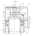
図1に示す打込機10は、ハウジング11、射出部12、打撃部13、トリガ14、プッシュレバー15、トリガバルブ16及びプッシュレバーバルブ17を有する。ハウジング11は、胴部18、ハンドル19及びヘッドカバー20を有する。胴部18は筒形状あり、ハンドル19は胴部18に接続されている。ヘッドカバー20は、胴部18の長手方向で第1端部に固定されており、ヘッドカバー20は、胴部18の開口部を塞いでいる。また、射出部12は、胴部18の長手方向で第2端部に固定されている。プラグ21がハンドル19に設けられ、プラグ21にエアホースが接続される。
A
胴部18内にシリンダ22が設けられている。シリンダ22は、ハウジング11に対して中心線A1に沿った方向に移動可能である。中心線A1は、シリンダ22の中心線である。打撃部13は、シリンダ22の内部及び外部に亘って配置されている。打撃部13は、シリンダ22に対して中心線A1に沿った方向に作動可能である。蓄圧室23が、ハンドル19内、胴部18内、ヘッドカバー20内に亘って設けられている。エアホースから供給される圧縮空気は、蓄圧室23に溜められる。
A
基部70、ヘッドキャップ27及びバルブシート31が、ヘッドカバー20内に配置されている。基部70はヘッドカバーに20に固定され、ヘッドキャップ27は基部70に固定され、バルブシート31はヘッドキャップ27に固定されている。ヘッドキャップ27は、金属製、例えば、鋼製、アルミニウム合金製である。排気通路28が、ヘッドカバー20、基部70及びヘッドキャップ27に亘って設けられている。排気通路28は、ハウジング11の外部B1につながっている。
A
基部70は、エキゾーストバルブ室26を有し、エキゾーストバルブ室26は、通路25につながっている。ヘッドキャップ27は、ガイド孔71を有し、エキゾーストバルブ30がガイド孔71に配置されている。エキゾーストバルブ30は、ヘッドキャップ27に対して中心線A1に沿った方向に移動可能である。バルブシート31は、合成ゴム製であり、バルブシート31はピストン上室32及び通路29を有する。通路29は、圧縮空気が通過可能な孔である。ピストン上室32は、通路29につながっている。エキゾーストバルブ30は、通路29及びピストン上室32の外に配置されている。
The
打撃部13は、ピストン33及びドライバブレード34を有する。ピストン33及びドライバブレード34は、一体成型品でもよい。ピストン33とドライバブレード34とは、別部品を固定したものでもよい。ピストン33はシリンダ22内に設けられ、ピストン33は、シリンダ22に対して中心線A1に沿った方向に作動可能である。ピストン33は、ピストン上室32の圧力により、中心線A1に沿った方向でバルブシート31から離間する向きで付勢される。ピストン33の外周面にシール部材97が取り付けられている。シール部材97は、シリンダ22の内周面に接触する。
The
図1のように、シリンダ22内における中心線A1に沿った方向で、ピストン33と射出部12との間に、ピストン下室35が設けられている。シール部材97は、ピストン上室32とピストン下室35とを隔てる。戻し空気室36が、胴部18とシリンダ22との間に設けられている。シリンダ22を径方向に貫通する通路37,38が設けられている。図2のように、逆止弁98がシリンダ22の外周に取り付けられている。逆止弁98は、シリンダ22内の圧力で作動し、かつ、通路37を開閉する。図3に示す通路38は、ピストン下室35と戻し空気室36とを、常に接続する。通路38は、中心線A1に沿った方向で通路37と射出部12との間に配置されている。
As shown in FIG. 1, a piston
さらに、図3に示すバンパ39が、胴部18内に設けられている。バンパ39の一部は、シリンダ22内に配置され、かつ、射出部12に接触している。バンパ39は、合成ゴム製である。バンパ39は、軸孔40を有する。
Further, a
さらに、図3のように、付勢部材としてのスプリング41が、胴部18内に設けられている。スプリング41は、シリンダ22を中心線A1に沿った方向でバルブシート31に近付ける向きで付勢する。通路42が、シリンダ22の端部とバルブシート31との間に形成される。射出部12は、胴部18に固定されている。図3のように、射出部12は、射出路43を有する。射出路43は、軸孔40につながっている。ドライバブレード34は、軸孔40及び射出路43内で中心線A1に沿った方向に作動可能である。
Furthermore, as shown in FIG. 3, a
図2のように、ホルダ44が胴部18の内部に設けられている。ホルダ44は環状であり、ホルダ44は、シリンダ22の径方向で、シリンダ22の外に配置されている。ホルダ44は通路45を有し、通路45は蓄圧室23につながっている。フランジ46,47が、シリンダ22の外周面に設けられている。制御室49が、フランジ46とフランジ47との間に設けられている。制御室49は、通路45によって蓄圧室23につながっている。
As shown in FIG. 2, a
ヘッドカバー20内と胴部18内とを隔てる隔壁99が設けられている。隔壁99とフランジ46との間に制御室50が形成されている。胴部18は、通路51を有し、制御室50は通路51につながっている。通路51は、通路25につながっている。フランジ46は、制御室49,50の圧力を受け、フランジ47は、制御室49の圧力を受ける。シリンダ22は、制御室49,50の圧力、及びスプリング41の付勢力により、中心線A1に沿った方向に付勢される。
A
トリガ14は、図3のようにハウジング11に取り付けられている。トリガ14は、支持軸52を中心として、所定角度の範囲内で作動可能である。スプリングが支持軸52に取り付けられ、スプリングは、トリガ14を支持軸52を中心として時計回りに付勢する。作業者がハンドル19を手で握り、かつ、指でトリガ14に操作力を付加すると、トリガ14は、スプリングの付勢力に抗して反時計回りに作動可能である。作業者がトリガ14に対する付勢力を解除すると、トリガ14は、スプリングの付勢力で時計回りに作動する。
プッシュレバー15は、図3のように射出部12に取り付けられている。プッシュレバー15は、ハウジング11及び射出部12に対して、中心線A1に沿った方向に作動可能である。プッシュレバー15は、スプリングにより、ハウジング11から離間する向きで付勢されている。スプリングにより付勢されるプッシュレバー15は、ストッパ55に接触して初期位置で停止する。プッシュレバー15の先端が対象物W1に押し付けられると、プッシュレバー15は、スプリングの付勢力に抗してハウジング11に近づく向きで作動可能である。
The
トリガバルブ16及びプッシュレバーバルブ17の構造が、図3に示されている。トリガバルブ16は、筒形状のガイド部56、ボール形状の弁部材57、プランジャ58及び通路59を有する。ガイド部56は、ハウジング11に取り付けられている。プランジャ58は、ガイド部56に対して作動可能である。トリガ14に対する操作力が解除されていると、トリガ14はプランジャ58から離間しており、トリガバルブ16は初期状態である。初期状態であるトリガバルブ16は、蓄圧室23と通路59とを遮断し、通路59と外部B1とを接続している。
The structures of the
図5のように、トリガ14に操作力が付加されてプランジャ58が作動すると、トリガバルブ16は、初期状態から作動状態に切り替わる。作動状態であるトリガバルブ16は、蓄圧室23と通路59とを接続し、かつ、通路59と外部B1とを遮断する。このため、蓄圧室23の圧縮空気は、通路59へ流れ込む。
As shown in FIG. 5, when an operating force is applied to the
プッシュレバーバルブ17は、圧力室60、バルブボディ61、プランジャ62、弁部材63及びスプリングを有する。圧力室60は、通路59につながっている。バルブボディ61は、ハウジング11に取り付けられ、プランジャ62及び弁部材63は、バルブボディ61に対してそれぞれ作動可能である。バルブボディ61は、排気通路65を有する。スプリングは、弁部材63をプランジャ62に近ける向きで付勢する。
The
また、伝達部材66が設けられ、伝達部材66は、バルブボディ61に対して作動可能である。伝達部材66は筒形状であり、バルブボディ61の一部は、伝達部材66内に配置されている。伝達部材66内にスプリング67が設けられている。スプリング67は、プランジャ62を、弁部材63から離間させる向きで付勢する。また、プッシュレバー15は、アーム68を有し、アーム68と伝達部材66とが、動力伝達可能に接続されている。
A
プッシュレバー15が対象物W1から離間していると、プッシュレバー15は初期位置で停止している。プッシュレバー15から伝達部材66に作動力は伝達されず、伝達部材66は初期位置で停止している。また、プッシュレバーバルブ17は、図3に示す初期状態にある。プッシュレバーバルブ17が初期状態にあると、プランジャ62は初期位置で停止し、かつ、排気通路65を開いている。また、弁部材63は、圧力室60と通路51とを遮断している。
When the
これに対して、作業者がプッシュレバー15を対象物W1に押し付け、プッシュレバー15が作動されると、プッシュレバー15の作動力は、アーム68によって伝達部材66に伝達され、伝達部材66は、初期位置から弁部材63に近づく向きで作動する。すると、プッシュレバーバルブ17は、初期状態から、図5に示す作動状態に切り替わる。プッシュレバーバルブ17が作動状態にあると、プランジャ62が排気通路65を遮断し、かつ、プランジャ62の作動力で弁部材63がスプリングの付勢力に抗して作動し、圧力室60と通路51とを接続する。
On the other hand, when the operator presses the
図1及び図3に示すマガジン85が、打込機10に取り付けられている。マガジン85は、釘86を収容している。マガジン85は、射出部12及びハンドル19によって支持されている。フィーダ87がマガジン85に設けられ、フィーダ87は、釘86を射出路43へ送る。
A
打込機10の使用例を説明する。作業者が、図3に示すようにトリガ14に対する操作力を解除し、かつ、プッシュレバー15を対象物W1から離間させていると、トリガバルブ16は初期状態にあり、かつ、プッシュレバーバルブ17は初期状態にある。つまり、トリガバルブ16は、蓄圧室23と通路59とを遮断している。また、プッシュレバーバルブ17は、プッシュレバーバルブ17は、圧力室60と通路51とを遮断し、通路51と排気通路65とを接続している。
A usage example of the
エキゾーストバルブ室26は、通路25,51及び排気通路65を介してハウジング11の外部B1につながっている。このため、エキゾーストバルブ30は、図2のようにホルダに接触した初期位置で停止している。エキゾーストバルブ30が、初期位置で停止していると、エキゾーストバルブ30は、ヘッドキャップ27の端面77から離間している。つまり、エキゾーストバルブ30は、通路29を開いており、ピストン上室32とハウジング11の外部とが接続されている。したがって、ピストン上室32は、排気通路28を介して外部B1につながっている。ピストン上室32の圧力は、略大気圧と同じである。
The
また、制御室50は、通路51及び排気通路65を介してハウジング11の外部B1につながっている。このため、シリンダ22は、制御室49の圧力、及びスプリング41の付勢力でバルブシート31に押し付けられ、通路42が閉じられている。したがって、蓄圧室23の圧縮空気は、ピストン上室32に供給されず、打撃部13は上死点で停止している。打撃部13が上死点で停止していると、ピストン33はバルブシート31に接触している。ピストン下室35は、軸孔40を介して外部B1につながっており、ピストン下室35の圧力は、略大気圧である。
Also, the
作業者がトリガ14に操作力を付加すると、トリガ14は図3で反時計回りに作動し、トリガ14は図5の作動位置で停止する。すると、トリガバルブ16は初期状態から作動状態に切り替わる。また、作業者がプッシュレバー15を対象物W1に接触させ、プッシュレバー15がハウジング11へ近づく向きで作動すると、プッシュレバーバルブ17は、初期状態から作動状態に切り替わる。
When the operator applies an operating force to the
トリガバルブ16が作動状態であり、かつ、プッシュレバーバルブ17が作動状態であると、蓄圧室23の圧縮空気の一部は、通路59、圧力室60及び通路51,25を通ってエキゾーストバルブ室26に供給される。すると、図4のように、エキゾーストバルブ30が作動し、エキゾーストバルブ30が端面77に押し付けられて停止する。つまり、エキゾーストバルブ30は通路29を閉じ、ピストン上室32と外部B1とが遮断される。また、蓄圧室23の圧縮空気の一部は、通路51を通って制御室50に供給される。すると、シリンダ22がバルブシート31から離間する向きで作動し、通路42が開く。さらに、蓄圧室23の圧縮空気の一部が、シリンダ22とバルブシート31との隙間を通ってピストン上室32へ流れ込み、ピストン上室32の圧力が上昇する。このため、打撃部13は、図6のように上死点から下死点に向けて作動、つまり、下降する。打撃部13が下降すると、ドライバブレード34は、射出路43内の釘86を打撃し、釘86が対象物W1に打ち込まれる。
When the
打撃部13が下降中、シール部材97が、通路37とバンパ39との間へ移動すると、逆止弁98は、シリンダ22内に流れ込む圧縮空気の圧力で作動して通路37を開く。このため、シリンダ22内の圧縮空気の一部は、通路37を通って戻し空気室36へ流れ込む。打撃部13が下降して、図7のようにピストン33がバンパ39に衝突すると、バンパ39は、打撃部13の運動エネルギの一部を吸収する。また、打撃部13は下死点で停止する。打撃部13が下死点で停止すると、ピストン33がバンパ39に押し付けられ、ピストン33は、ピストン下室35と軸孔40とを遮断する。
When the
打撃部13が釘86を対象物W1に打ち込んだ反動により、プッシュレバー15は、図9のように対象物W1から離間する。すると、プッシュレバー15はスプリングの付勢力で作動して初期位置で停止する。このため、プッシュレバーバルブ17は、作動状態から初期状態に切り替わる。また、作業者は、トリガ14に対する操作力を解除する。このため、トリガバルブ16は、作動状態から初期状態に切り替わる。
The
すると、プッシュレバーバルブ17が初期状態であり、かつ、トリガバルブ16が初期状態であると、エキゾーストバルブ30は、ピストン上室32の圧力で作動して端面77から離間し、通路29と排気通路28とを接続する。エキゾーストバルブ30は、図8のように基部70に接触し、かつ、初期位置で停止する。このため、ピストン上室32の圧縮空気は、排気通路28を通って外部B1に排出される。ピストン上室32の圧力は、略大気圧になる。
Then, when the
さらに、制御室50の圧縮空気、及びエキゾーストバルブ室26の圧縮空気は、図8及び図9のように、通路51及び排気通路65を通って外部B1へ排出される。このため、シリンダ22は、図8のようにバルブシート31に近づく向きで作動し、通路42を閉じて停止する。また、ピストン33は、戻し空気室36から通路38を通ってピストン下室35に流れ込む圧縮空気の圧力を受けており、打撃部13は、図9のように下死点から上死点に向けて作動する。そして、ピストン33が、図1のようにバルブシート31に接触すると、打撃部13は上死点で停止する。打撃部13が上死点で停止した後、ピストン下室35の空気は、軸孔40を通って外部B1に排出され、ピストン下室35の圧力は、略大気圧になる。
Further, the compressed air in the
次に、ヘッドキャップ27及びエキゾーストバルブ30の具体例を、図10(A)、図10(B)及び図11に基づいて説明する。エキゾーストバルブ30は、合成樹脂製または合成ゴム製である。合成樹脂して例えば、熱可塑性樹脂、具体的にはウレタン樹脂を用いることが可能である。合成ゴムとして、ウレタンゴムを用いることが可能である。エキゾーストバルブ30は、壁部78と、壁部78に接続された筒部79と、を有する。エキゾーストバルブ30は、中心線A1に対して交差する第2平面内、例えば、図11のように、中心線A1に対して垂直な平面内における外面形状が円形である。通路29及び開口部29Aの形状は、円形である。ガイド孔71の内径は、通路29の開口部29Aの内径よりも大きい。
Next, specific examples of the
エキゾーストバルブ30の外径は、ガイド孔71の外径よりも大きい。エキゾーストバルブ30の外周面は、ヘッドキャップ27に押し付けられ、かつ、弾性変形している。エキゾーストバルブ30は、ガイド孔71内で中心線A1に沿った方向に作動可能である。エキゾーストバルブ30は、基部70と端面77との間に配置されている。エキゾーストバルブ30の中心線A1に沿った方向における端部83が、基部70に接触可能である。
The outer diameter of
エキゾーストバルブ30は、接触部80、非接触部81及び膨らみ部82を有する。接触部80、非接触部81及び膨らみ部82は、中心線A1に沿った方向で端部83の反対に位置している。膨らみ部82は、壁部78に設けられている。中心線A1に対して交差する第2平面内で、接触部80及び非接触部81は、中心線A1を中心として環状に配置されている。中心線A1に対して交差する、例えば、中心線A1に対して略90度の角度で交差する方向D1、つまり、通路29の径方向において、非接触部81は、接触部80よりも内側に位置し、かつ、膨らみ部82よりも外側に位置する。接触部80と非接触部81とが同心状に配置されている。接触部80は、図11に示すように、中心線A1に対して交差する第2平面内で、通路29の開口部29Aも外側に配置されている。非接触部81及び膨らみ部82は、中心線A1に対して交差する第2平面内で、通路29の開口部29Aも内側にそれぞれ配置されている。
The
また、図10(A)に示されるように、中心線A1に沿った方向で、端部83から膨らみ部82の先端までは長さL1を有する。中心線A1に沿った方向で、端部83から接触部80の先端までは長さL2を有する。中心線A1に沿った方向で、端部83から非接触部81までは長さL3を有する。長さL2は、長さL1より小さく、かつ、長さL3より大きい。つまり、非接触部81は、接触部と膨らみ部82との間に配置された凹部または窪みである。膨らみ部82は、中心線A1に沿った第1平面内で、非接触部81から通路29に向けて突出されている。
Further, as shown in FIG. 10A, the length L1 is provided from the
エキゾーストバルブ30は、中心線A1に沿った方向における位置に関わり無く、エキゾーストバルブ室26と排気通路28とを気密に隔てる。また、エキゾーストバルブ30は、端面77に接触及び離間可能である。通路29と排気通路28とを接続及び遮断する機能を有する。図10(A)のように、エキゾーストバルブ30の接触部80が端面77から離間していると、通路29と排気通路28とが接続されている。
The
エキゾーストバルブ室26の圧力が上昇すると、エキゾーストバルブ30は、中心線A1に沿った方向の圧力により、端面77に近づくように作動する。そして、図10(B)及び図12(A)のように、エキゾーストバルブ30の接触部80が端面77に接触する。さらに、接触部80が弾性変形すると、図12(B)のように、接触部80は端面77に密着し、通路29と排気通路28とが遮断される。
When the pressure in the
接触部80が端面77に接触した時点から、接触部80が弾性変形して端面77に密着するまでの間、中心線A1を中心とする径方向で、エキゾーストバルブ30のうち、接触部80よりも内側の箇所は、ヘッドキャップ27の端面77から離間している。つまり、エキゾーストバルブ30と端面77との間に、中心線A1に沿った方向の隙間がある。また、接触部80が弾性変形して端面77に密着し、かつ、非接触部81が弾性変形して、非接触部81及び接触部80が、略直線形状になったとしても、非接触部81は、開口部29Aに位置し、端面77には接触しない。つまり、エキゾーストバルブ30の表面が、開口部29Aを形成するヘッドキャップ27のエッジに押し付けられることを回避可能である。
From the time the
このため、エキゾーストバルブ30のうち、ヘッドキャップ27のエッジに対応する箇所で応力が集中することを回避できる。したがって、エキゾーストバルブ30がヘッドキャップ27に接触及び離間する動作が繰り返されたとしても、エキゾーストバルブ30の強度が低下することを抑制できる。言い換えると、エキゾーストバルブ30の寿命が相対的に長くなる。また、エキゾーストバルブ30が、通路29と排気通路28とを遮断する機能、つまり、シール性が低下することを抑制できる。さらに、エキゾーストバルブ30の材料として、低強度材を使用可能であり、エキゾーストバルブ30の材料として、高強度材を使用する場合に比べて、エキゾーストバルブ30の製造コストを低減可能である。
Therefore, it is possible to avoid concentration of stress at a portion of the
さらに、開口部29Aは、中心線A1に沿った第2平面内で角部を除去した面取りが施されている。面取りの形状は、例えば、円弧状に湾曲した面取り、直線状の形状の面取りの何れでもよい。円弧状に湾曲した面取りは、“R面取り”と呼ばれる。直線状の面取りは、“C面取り”と呼ばれる。このため、エキゾーストバルブ30のうち、ヘッドキャップ27のエッジに対応する箇所で応力が集中することを、一層確実に回避できる。
Further, the
さらに、図10(A)のように、壁部78の内面84の一部、及び膨らみ部82の表面は、点B2を中心とする球面である。点B2は、中心線A1上に位置する。そして、点B2を中心とする仮想円の径方向で、壁部78の厚さT1は、点B2を中心とする仮想円の円周方向の何れの箇所でも一定である。このため、エキゾーストバルブ室26の圧力を受けるエキゾーストバルブ30は、弾性変形量が均一になり、エキゾーストバルブ30における応力の集中を、一層確実に回避できる。
Further, as shown in FIG. 10A, a portion of the
次に、ヘッドキャップ27及びエキゾーストバルブ30の他の具体例を、図13(A)、図13(B)を参照して説明する。エキゾーストバルブ30は、接触部88及び非接触部100を有する。図14のように、中心線A1に対して交差する第2平面内で、接触部88は中心線A1を中心として環状に配置されている。非接触部100は、中心線A1に対して交差する第2平面内で、接触部88よりも内側に配置されている。非接触部100の外周形状は、中心線A1を中心とする円形である。接触部88と非接触部100とが、同心状に配置されている。非接触部100は、中心線A1に対して垂直な平坦面である。端部83から接触部88の先端までの長さL4は、端部83から非接触部100までの長さL5よりも大きい。つまり、非接触部100は、中心線A1を中心とする径方向で、接触部88の内側に配置された凹部または窪みとして定義可能である。
Next, another specific example of the
接触部88の外側にテーパ面89が設けられ、テーパ面89の外側にテーパ面90が設けられている。テーパ面89及びテーパ面90は、共に中心線A1を中心として環状に配置されている。テーパ面89及びテーパ面90は、中心線A1に対して傾斜されている。テーパ面90は、中心線A1を中心とする径方向、つまり、方向D1において、テーパ面89よりも外側に配置されている。テーパ面89とテーパ面90とが、端面91によって接続されている。
A tapered
図13(A)に示されたエキゾーストバルブ30は、通路29と排気通路28とを接続及び遮断する機能を有する。図13(A)のように、エキゾーストバルブ30の接触部88が端面77から離間していると、通路29と排気通路28とが接続されている。
The
エキゾーストバルブ室26の圧力が上昇すると、エキゾーストバルブ30は、中心線A1に沿った方向の圧力により、端面77に近づくように作動する。そして、図13(B)のように、エキゾーストバルブ30の接触部88が端面77に接触する。さらに、接触部88が弾性変形すると、接触部88は端面77に密着し、通路29と排気通路28とが遮断される。
When the pressure in the
接触部88が端面77に接触した時点から、接触部88が弾性変形して端面77に密着するまでの間、中心線A1を中心とする径方向で、エキゾーストバルブ30のうち、接触部88よりも内側の箇所は、ヘッドキャップ27の端面77から離間している。つまり、エキゾーストバルブ30と端面77との間に、中心線A1に沿った方向の隙間がある。したがって、図13(B)に示すエキゾーストバルブ30は、強度が低下することを抑制でき、図10(B)に示されたエキゾーストバルブ30と同様の効果を得ることができる。
From the time when the
さらに、図13(A)のように、非接触部100は、壁部78の表面の一部である。そして、壁部78は、中心線A1に沿った方向の厚さT2は一定である。このため、エキゾーストバルブ室26の圧力を受けるエキゾーストバルブ30は、弾性変形量が均一になり、エキゾーストバルブ30における応力の集中を、一層確実に回避できる。
Furthermore, as shown in FIG. 13A, the
次に、ヘッドキャップ27及びエキゾーストバルブ30の他の具体例を、図15(A)、図15(B)を参照して説明する。エキゾーストバルブ30は、接触部88につながるテーパ面90を有する。図15(A)に示されたエキゾーストバルブ30は、図13に示されたテーパ面89及び端面91を備えていない。図15(A)は、接触部88が端面77から離間した状態であり、図15(B)は、接触部88が端面77に接触した状態である。図15(A)、図15(B)に示されたエキゾーストバルブ30は、図13(A)、図13(B)に示されたエキゾーストバルブ30と同様の効果を得ることができる。
Next, another specific example of the
本実施形態で説明した構成の技術的意味の一例は、次の通りである。打込機10は、打込機の一例である。打撃部13は、打撃部の一例である。ピストン上室32は、第1圧力室の一例である。ハウジング11は、ハウジングの一例である。ヘッドキャップ27は、弁座の一例である。エキゾーストバルブ30は、弁体の一例である。通路29は、通路の一例である。
An example of the technical meaning of the configuration described in this embodiment is as follows. The
図10(A)、図13(A)、図15(A)において、中心線A1に沿った方向は、第2方向の一例である。図10(A)、図13(A)、図15(A)において、中心線A1に対して交差する方向、つまり、中心線A1に対して略90度で交差する方向D1は、第1方向の一例である。図11及び図14は、それぞれ“弁体の作動方向である第2方向に対して交差する第1方向を含む第1平面”の一例である。図10(A)、図10(B)、図13(A)、図13(B)、図15(A)、図15(B)は、それぞれ“弁体の作動方向に沿った第2方向を含む第2平面”の一例である。 In FIGS. 10A, 13A, and 15A, the direction along the center line A1 is an example of the second direction. In FIGS. 10A, 13A, and 15A, the direction intersecting the center line A1, that is, the direction D1 intersecting the center line A1 at approximately 90 degrees is the first direction. is an example. 11 and 14 are examples of "a first plane including a first direction that intersects the second direction, which is the operating direction of the valve body", respectively. FIGS. 10(A), 10(B), 13(A), 13(B), 15(A), and 15(B) each show a “second direction along the actuation direction of the valve body”. is an example of a "second plane" containing
開口部29Aは、開口部の一例である。接触部80,88は、それぞれ接触部の一例である。非接触部81,100は、それぞれ非接触部の一例である。膨らみ部82は、膨らみ部の一例である。開口部29Aは、湾曲部の一例である。蓄圧室23は、蓄圧室の一例である。エキゾーストバルブ室26は、第2圧力室の一例である。トリガバルブ16及びプッシュレバーバルブ17は、バルブの一例である。トリガ14は、トリガの一例である。プッシュレバー15は、プッシュレバーの一例である。射出部12は、射出部の一例である。マガジン85は、マガジンの一例である。釘86は、止具の一例である。
The
打込機は、開示した実施形態に限定されるものではなく、その要旨を逸脱しない範囲で種々変更可能である。蓄圧室に供給する圧縮性気体は、空気に代えて不活性ガス、例えば、窒素ガスまたは希ガスであってもよい。トリガは、レバー、ボタン、アームなどを含む。操作部材の作動は、所定角度範囲内での回転作動、直線状の往復作動の何れでもよい。プッシュレバーは、軸形状、中空形状の何れでもよい。ハウジングは、ケーシングまたはボディと呼ばれる要素でもよい。第1圧力室及び第2圧力室は、それぞれ圧縮空気が供給及び排出される空間である。通路は、気体が通過可能な孔、隙間、溝を含む。 The fastening tool is not limited to the disclosed embodiments, and various modifications can be made without departing from the scope of the invention. The compressible gas supplied to the accumulator may be inert gas such as nitrogen gas or rare gas instead of air. Triggers include levers, buttons, arms, and the like. The operation of the operating member may be either a rotary operation within a predetermined angular range or a linear reciprocating operation. The push lever may be shaft-shaped or hollow-shaped. The housing may be an element called casing or body. The first pressure chamber and the second pressure chamber are spaces into which compressed air is supplied and discharged, respectively. Passages include holes, gaps, and grooves through which gas can pass.
10…打込機、11…ハウジング、12…射出部、13…打撃部、14…トリガ、15…プッシュレバー、16…トリガバルブ、17…プッシュレバーバルブ、23…蓄圧室、26…エキゾーストバルブ室、26…エキゾーストバルブ室、27…ヘッドキャップ、29…通路、29A…開口部、30…エキゾーストバルブ、32…ピストン上室、80,88…接触部、81,100…非接触部、82…膨らみ部、85…マガジン、D1…方向
DESCRIPTION OF
Claims (9)
気体の圧力で前記打撃部を作動させる第1圧力室と、
前記打撃部及び前記第1圧力室が設けられたハウジングと、前記ハウジング内に固定して設けられた弁座と、
前記弁座に設けられ、かつ、前記第1圧力室と前記ハウジングの外部とをつなぐ通路と、
前記ハウジング内に作動可能に設けられ、かつ、前記弁座に接触及び離間されることにより、前記通路を開閉する弁体と、
を有する、打込機であって、
前記弁体は、前記第1圧力室の外に配置された接触部及び非接触部を備え、
前記接触部は、前記弁体の作動方向に対して交差する第1方向における前記通路の径方向において、前記通路よりも外側で前記弁座に接触及び離間されて前記通路を開閉し、
前記非接触部は、前記第1方向における前記通路の径方向において前記接触部よりも内側に設けられ、
前記非接触部は、前記弁体の作動方向である第2方向において前記接触部が前記弁座に接触された状態で、前記弁体の作動方向で前記弁座から離間する位置に設けられている、打込機。an operable striking portion;
a first pressure chamber for actuating the striking part with gas pressure;
a housing in which the striking portion and the first pressure chamber are provided; a valve seat fixedly provided in the housing;
a passage provided in the valve seat and connecting the first pressure chamber and the outside of the housing;
a valve body that is operably provided in the housing and that opens and closes the passage by being in contact with and separated from the valve seat;
A fastening tool comprising:
the valve body includes a contact portion and a non-contact portion arranged outside the first pressure chamber;
the contact portion is in contact with and separated from the valve seat outside the passage in a radial direction of the passage in a first direction that intersects the operating direction of the valve body to open and close the passage;
The non-contact portion is provided inside the contact portion in a radial direction of the passage in the first direction,
The non-contact portion is provided at a position separated from the valve seat in the operating direction of the valve body while the contact portion is in contact with the valve seat in the second direction, which is the operating direction of the valve body. There is a hammer.
前記膨らみ部は、前記第2方向において前記第1圧力室に向けて突出されている、請求項1または2記載の打込機。The valve body has a bulging portion arranged inside the non-contact portion in a radial direction of the passage in the first direction,
3. The fastening tool according to claim 1, wherein said bulging portion protrudes toward said first pressure chamber in said second direction.
前記蓄圧室から前記気体が供給され、かつ、前記気体の圧力により前記弁体を前記弁座に近づけるように作動させる第2圧力室と、
前記第2圧力室を前記ハウジングの外部に接続し、かつ、前記第2圧力室を前記蓄圧室から遮断する初期状態、及び前記第2圧力室を前記蓄圧室に接続し、かつ、前記第2圧力室を前記ハウジングの外部から遮断する作動状態とで切り替えが可能なバルブと、
前記ハウジングに設けられ、かつ、操作力が付加及び解除されるトリガと、
前記ハウジングに設けられ、かつ、前記打撃部により打撃される止具を打ち込む対象物に接触及び離間が可能なプッシュレバーと、
前記ハウジングに設けられ、かつ、前記打撃部の作動をガイドする射出部と、
前記射出部へ供給する前記止具を収容するマガジンと、
を更に備え、
前記バルブは、前記トリガに対する操作力が解除されているか、または、前記プッシュレバーが前記対象物から離間されていると、前記初期状態にあり、
前記バルブは、前記トリガに対して操作力が付加され、かつ、前記プッシュレバーが前記対象物に接触されていると、前記作動状態にある、請求項1乃至8の何れか1項記載の打込機。an accumulator chamber provided in the housing and containing the gas;
a second pressure chamber to which the gas is supplied from the pressure accumulating chamber and to operate the valve body to approach the valve seat by the pressure of the gas;
An initial state in which the second pressure chamber is connected to the outside of the housing and the second pressure chamber is isolated from the pressure accumulation chamber, and an initial state in which the second pressure chamber is connected to the pressure accumulation chamber and the second pressure chamber is connected a valve that can be switched between an operating state that isolates the pressure chamber from the outside of the housing;
a trigger provided on the housing and to which an operating force is applied and released;
a push lever provided on the housing and capable of coming into contact with and separating from an object into which the fastener struck by the striking portion is to be driven;
an injection part provided in the housing and guiding the operation of the striking part;
a magazine containing the fasteners to be supplied to the injection section;
further comprising
the valve is in the initial state when the operating force on the trigger is released or the push lever is separated from the object;
9. A strike according to any one of claims 1 to 8, wherein the valve is in the actuated state when an operating force is applied to the trigger and the push lever is in contact with the object. loading machine.
Applications Claiming Priority (3)
| Application Number | Priority Date | Filing Date | Title |
|---|---|---|---|
| JP2019215115 | 2019-11-28 | ||
| JP2019215115 | 2019-11-28 | ||
| PCT/JP2020/040882 WO2021106495A1 (en) | 2019-11-28 | 2020-10-30 | Driving tool |
Publications (2)
| Publication Number | Publication Date |
|---|---|
| JPWO2021106495A1 JPWO2021106495A1 (en) | 2021-06-03 |
| JP7298710B2 true JP7298710B2 (en) | 2023-06-27 |
Family
ID=76128891
Family Applications (1)
| Application Number | Title | Priority Date | Filing Date |
|---|---|---|---|
| JP2021561246A Active JP7298710B2 (en) | 2019-11-28 | 2020-10-30 | hammer |
Country Status (5)
| Country | Link |
|---|---|
| US (1) | US20230010405A1 (en) |
| JP (1) | JP7298710B2 (en) |
| CN (1) | CN114746217A (en) |
| TW (1) | TW202120271A (en) |
| WO (1) | WO2021106495A1 (en) |
Citations (4)
| Publication number | Priority date | Publication date | Assignee | Title |
|---|---|---|---|---|
| US3170487A (en) | 1962-07-09 | 1965-02-23 | Senco Products | Springless firing valve |
| JP4106576B2 (en) | 1998-08-31 | 2008-06-25 | 株式会社デンソー | Variable focus lens |
| JP6317373B2 (en) | 2013-03-05 | 2018-04-25 | 深▲せん▼市光峰光電技術有限公司Appotronics Corporation Limited | Wavelength conversion device, light emitting device, and projection system |
| WO2019171809A1 (en) | 2018-03-09 | 2019-09-12 | 工機ホールディングス株式会社 | Driving device and switching mechanism |
Family Cites Families (11)
| Publication number | Priority date | Publication date | Assignee | Title |
|---|---|---|---|---|
| JPS61117074A (en) * | 1984-11-09 | 1986-06-04 | 日立工機株式会社 | Feed apparatus of driver |
| JPS6317373U (en) * | 1986-07-18 | 1988-02-04 | ||
| JP2553343Y2 (en) * | 1991-02-28 | 1997-11-05 | エヌオーケー株式会社 | Solenoid valve |
| JP2578034Y2 (en) * | 1993-06-04 | 1998-08-06 | パロマ工業株式会社 | Gas valve |
| DE69629623T2 (en) * | 1995-06-09 | 2004-06-17 | Max Co. Ltd. | Outlet system for a machine for driving in nails |
| JPH091475A (en) * | 1995-06-16 | 1997-01-07 | Kanematsu Nnk Corp | Pneumatic type fixing apparatus driving device |
| JP3635596B2 (en) * | 1996-05-10 | 2005-04-06 | 日立工機株式会社 | Head valve sealing device for driving machine |
| TWM329356U (en) * | 2006-06-23 | 2008-04-01 | Quan-Yu Lai | Magnetism exhaust valve |
| JP4720656B2 (en) * | 2006-07-12 | 2011-07-13 | 日立工機株式会社 | Driving machine |
| CN201334913Y (en) * | 2008-12-30 | 2009-10-28 | 中国矿业大学 | Exhaust single hydraulic prop |
| CN103707266B (en) * | 2014-01-10 | 2015-07-22 | 浙江荣鹏气动工具有限公司 | Pneumatic nail gun |
-
2020
- 2020-10-30 WO PCT/JP2020/040882 patent/WO2021106495A1/en active Application Filing
- 2020-10-30 JP JP2021561246A patent/JP7298710B2/en active Active
- 2020-10-30 CN CN202080082369.5A patent/CN114746217A/en active Pending
- 2020-10-30 US US17/780,674 patent/US20230010405A1/en active Pending
- 2020-11-27 TW TW109141677A patent/TW202120271A/en unknown
Patent Citations (4)
| Publication number | Priority date | Publication date | Assignee | Title |
|---|---|---|---|---|
| US3170487A (en) | 1962-07-09 | 1965-02-23 | Senco Products | Springless firing valve |
| JP4106576B2 (en) | 1998-08-31 | 2008-06-25 | 株式会社デンソー | Variable focus lens |
| JP6317373B2 (en) | 2013-03-05 | 2018-04-25 | 深▲せん▼市光峰光電技術有限公司Appotronics Corporation Limited | Wavelength conversion device, light emitting device, and projection system |
| WO2019171809A1 (en) | 2018-03-09 | 2019-09-12 | 工機ホールディングス株式会社 | Driving device and switching mechanism |
Also Published As
| Publication number | Publication date |
|---|---|
| JPWO2021106495A1 (en) | 2021-06-03 |
| TW202120271A (en) | 2021-06-01 |
| US20230010405A1 (en) | 2023-01-12 |
| CN114746217A (en) | 2022-07-12 |
| WO2021106495A1 (en) | 2021-06-03 |
Similar Documents
| Publication | Publication Date | Title |
|---|---|---|
| WO2017115593A1 (en) | Driver | |
| JP5509770B2 (en) | Air driving machine | |
| US5873510A (en) | Repetitive striking type pneumatically operated nail gun | |
| US7980439B2 (en) | Nailing machine | |
| US7296721B1 (en) | Pneumatic nail gun having nail pusher | |
| US7490747B2 (en) | Fastener driving tool including push lever configured to avoid inclined orientation of the driver fasteners | |
| TWI549788B (en) | Driving tool and bumper of driving tool | |
| US7490748B2 (en) | Pneumatically operated fastener driving tool | |
| US7690546B2 (en) | Pneumatic tool actuation device | |
| JP7298710B2 (en) | hammer | |
| US10646984B2 (en) | Powered fastener-driving tool including an engaging element to frictionally engage a piston upon returning to a pre-firing position | |
| US20120160889A1 (en) | Fastening Tool for Adjusting a Driving Depth of a Fastener | |
| WO2019171809A1 (en) | Driving device and switching mechanism | |
| TWI587988B (en) | High efficiency pneumatic nailer | |
| JP2017119330A (en) | Driving machine | |
| JP7205612B2 (en) | hammer | |
| JP6927030B2 (en) | Driving machine | |
| JP7293876B2 (en) | hammer | |
| JP7156497B2 (en) | hammer | |
| JP2020146821A (en) | Driving machine | |
| JPS6236621Y2 (en) | ||
| JPS5938999Y2 (en) | Holding device for impact driver in impact tool | |
| JPS6125987Y2 (en) | ||
| JPS5939000Y2 (en) | Holding device for impact driver in impact tool | |
| JP2020127993A (en) | Driving machine |
Legal Events
| Date | Code | Title | Description |
|---|---|---|---|
| A621 | Written request for application examination |
Free format text: JAPANESE INTERMEDIATE CODE: A621 Effective date: 20220526 |
|
| TRDD | Decision of grant or rejection written | ||
| A01 | Written decision to grant a patent or to grant a registration (utility model) |
Free format text: JAPANESE INTERMEDIATE CODE: A01 Effective date: 20230516 |
|
| A61 | First payment of annual fees (during grant procedure) |
Free format text: JAPANESE INTERMEDIATE CODE: A61 Effective date: 20230529 |
|
| R150 | Certificate of patent or registration of utility model |
Ref document number: 7298710 Country of ref document: JP Free format text: JAPANESE INTERMEDIATE CODE: R150 |