JP7298564B2 - Shape change prediction method for press-formed products - Google Patents
Shape change prediction method for press-formed products Download PDFInfo
- Publication number
- JP7298564B2 JP7298564B2 JP2020124218A JP2020124218A JP7298564B2 JP 7298564 B2 JP7298564 B2 JP 7298564B2 JP 2020124218 A JP2020124218 A JP 2020124218A JP 2020124218 A JP2020124218 A JP 2020124218A JP 7298564 B2 JP7298564 B2 JP 7298564B2
- Authority
- JP
- Japan
- Prior art keywords
- press
- formed product
- residual stress
- shape
- springback
- Prior art date
- Legal status (The legal status is an assumption and is not a legal conclusion. Google has not performed a legal analysis and makes no representation as to the accuracy of the status listed.)
- Active
Links
Images


Classifications
-
- Y—GENERAL TAGGING OF NEW TECHNOLOGICAL DEVELOPMENTS; GENERAL TAGGING OF CROSS-SECTIONAL TECHNOLOGIES SPANNING OVER SEVERAL SECTIONS OF THE IPC; TECHNICAL SUBJECTS COVERED BY FORMER USPC CROSS-REFERENCE ART COLLECTIONS [XRACs] AND DIGESTS
- Y02—TECHNOLOGIES OR APPLICATIONS FOR MITIGATION OR ADAPTATION AGAINST CLIMATE CHANGE
- Y02P—CLIMATE CHANGE MITIGATION TECHNOLOGIES IN THE PRODUCTION OR PROCESSING OF GOODS
- Y02P10/00—Technologies related to metal processing
- Y02P10/20—Recycling
Landscapes
- Shaping Metal By Deep-Drawing, Or The Like (AREA)
Description
本発明は、プレス成形品の形状変化予測方法に関し、特に、天板部と縦壁部とを有して側面視で前記天板部側に凸状に湾曲した形状を含むプレス成形品について、金型から離型してスプリングバックした後の時間経過に伴って生じる形状変化を予測するプレス成形品の形状変化予測方法に関する。 The present invention relates to a method for predicting shape change of a press-formed product, and in particular, for a press-formed product having a top plate portion and a vertical wall portion and including a convexly curved shape toward the top plate portion side in a side view, The present invention relates to a shape change prediction method for a press-formed product that predicts the shape change that occurs with the passage of time after the mold is released from the mold and springs back.
プレス成形は金属部品を低コストかつ短時間に製造することができる製造方法であり、多くの自動車部品の製造に用いられている。近年では、自動車の衝突安全性と車体の軽量化を両立するため、より高強度な金属板が自動車部品のプレス成形に利用されている。 Press molding is a manufacturing method capable of manufacturing metal parts at low cost and in a short period of time, and is used in the manufacture of many automobile parts. In recent years, higher-strength metal sheets have been used for press molding of automobile parts in order to achieve both collision safety of automobiles and weight reduction of automobile bodies.
高強度な金属板をプレス成形する場合の主な課題の一つにスプリングバックによる寸法精度の低下がある。プレス成形により金属板を変形させる際にプレス成形品に発生した残留応力が駆動力となり、金型から離型したプレス成形品がプレス成形前の金属板の形状にバネのように瞬間的に戻ろうとする現象をスプリングバックと呼ぶ。 One of the main problems in stamping high-strength metal sheets is the deterioration of dimensional accuracy due to springback. Residual stress generated in the press-formed product when the metal plate is deformed by press-forming acts as a driving force, and the press-formed product released from the mold instantly returns to the shape of the metal plate before press-forming like a spring. This phenomenon is called springback.
プレス成形時に発生する残留応力は高強度な金属板(例えば、高張力鋼板)ほど大きくなるため、スプリングバックによる形状変化も大きくなる。したがって高強度な金属板ほどスプリングバック後の形状を規定の寸法内におさめることが難しくなる。そこでスプリングバックによるプレス成形品の形状変化を精度良く予測する技術が重要となる。 The higher the strength of the metal plate (for example, a high-strength steel plate), the greater the residual stress generated during press forming, so the shape change due to springback also increases. Therefore, the higher the strength of the metal plate, the more difficult it becomes to keep the shape after springback within the specified dimensions. Therefore, it is important to have a technique for accurately predicting the shape change of press-formed products due to springback.
スプリングバックによる形状変化の予測には、有限要素法によるプレス成形シミュレーションの利用が一般的である。当該プレス成形シミュレーションにおける手順としては、まず、金属板を成形下死点までプレス成形する過程のプレス成形解析を行い、プレス成形下死点での残留応力を予測する第1段階(例えば特許文献1)と、金型から離型した(取り出した)プレス成形品がスプリングバックにより形状が変化する過程のスプリングバック解析を行い、離型したプレス成形品における力のモーメントと残留応力との釣り合いがとれる形状を予測する第2段階(例えば特許文献2)に分けられる。 For the prediction of shape change due to springback, it is common to use press forming simulation by the finite element method. As a procedure in the press-forming simulation, first, the press-forming analysis of the process of press-forming the metal plate to the forming bottom dead center is performed, and the first stage of predicting the residual stress at the press-forming bottom dead center (for example, Patent Document 1 ) and the springback analysis of the process in which the shape of the press-formed product released from the mold (taken out) changes due to springback, and the balance between the moment of force and the residual stress in the released press-formed product can be achieved. It is divided into a second stage of shape prediction (for example, Patent Document 2).
これまでに、前述した第1段階のプレス成形解析と第2段階のスプリングバック解析とを統合したプレス成形シミュレーションを行うことにより、金型から離型してスプリングバックしたプレス成形品の形状が予測されてきた。
しかしながら、発明者らは、プレス成形シミュレーションにより予測されたプレス成形品の形状と実際にプレス成形されたプレス成形品の形状とを比較した際、プレス成形シミュレーションによる形状予測精度が低くなるプレス成形品があることに気づいた。
So far, by performing a press-forming simulation that integrates the first-stage press-forming analysis and the second-stage springback analysis, the shape of the press-formed product that springs back after being released from the mold can be predicted. It has been.
However, when the inventors compared the shape of the press-formed product predicted by the press-forming simulation with the shape of the press-formed product that was actually press-formed, it was found that the shape prediction accuracy by the press-forming simulation was low. I noticed that there is
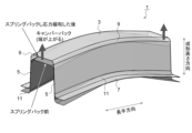
そこで、プレス成形シミュレーションによる形状予測精度が低くなるプレス成形品とその原因を調査したところ、一例として図8に示すような、天板部3と縦壁部5とフランジ部7とを有してなる断面ハット形状であり、側面視で天板部3側に凸状に湾曲したプレス成形品1においては、離型して数日経過した後では、プレス成形品1における長手方向の端部側が天板部3側に変形(以下、このような変形を「キャンバーバック」という。)が生じてしまい、プレス成形直後と数日経過後とではプレス成形品1の形状が異なることを発見した。
Therefore, when the press-formed product whose shape prediction accuracy by press-forming simulation becomes low and the cause thereof were investigated, as an example, as shown in FIG. In the press-formed
このようなプレス成形品の時間単位の経過に伴う経時変化は、クリープ現象のように外部から高い荷重を受け続ける構造部材が徐々に変形する現象(例えば、特許文献3)と類似しているように思われるが、外部から荷重を受けていないプレス成形品において起こる形状の変化はこれまでに知られていなかった。 Such changes over time in press-formed products appear to be similar to the phenomenon of gradual deformation of a structural member that continues to receive a high load from the outside, such as a creep phenomenon (for example, Patent Document 3). However, the shape change that occurs in press-formed products that are not subjected to an external load has not been known so far.
さらに、従来のプレス成形シミュレーションにおける第2段階(スプリングバック解析)は、金型から取り出した瞬間に生じるスプリングバックした直後のプレス成形品の形状を予測するものである。そのため、本願が目的とするスプリングバックしたプレス成形品について、例えば数日経過した後の形状変化を予測することに関しては、これまでに何ら検討されていなかった。
その上、スプリングバックしたプレス成形品の時間単位の経過による形状変化は、前述したように、外部からの荷重を受けずに生じるものである。そのため、プレス成形品の時間単位の経過による形状変化の予測を試みたとしても、クリープ現象による形状変化を取り扱う解析手法を適用することはできなかった。
Furthermore, the second step (springback analysis) in the conventional press-forming simulation predicts the shape of the press-formed product immediately after springback that occurs at the moment it is taken out from the mold. For this reason, no study has been made so far on predicting the shape change after several days have passed, for example, for the spring-back press-formed product, which is the object of the present application.
Moreover, the shape change over time of the spring-backed press-formed product occurs without receiving an external load, as described above. Therefore, even if an attempt was made to predict the shape change of a press-formed product over time, it was not possible to apply an analysis method that deals with the shape change due to the creep phenomenon.
本発明は、上記のような課題を解決するためになされたものであり、側面視で凸状に湾曲したプレス成形品について、金型から離型した瞬間にスプリングバックした後の時間単位の経過による前記プレス成形品の形状変化を予測するプレス成形品の形状変化予測方法を提案することを目的とする。 The present invention has been made in order to solve the above-mentioned problems, and for a press-molded product that is convexly curved in a side view, the elapse of time units after springback at the moment it is released from the mold An object of the present invention is to propose a press-formed product shape change prediction method for predicting the shape change of the press-formed product due to
(1)本発明に係るプレス成形品の形状変化予測方法は、天板部と該天板部から連続する縦壁部とを有して側面視で前記天板部側に凸状に湾曲した形状を含むプレス成形品について、金型から離型した瞬間にスプリングバックした後の時間経過に伴う応力緩和による形状変化を予測するものであって、
前記プレス成形品のスプリングバック解析により、スプリングバックした直後の前記プレス成形品の形状及び残留応力を取得するスプリングバック直後の形状・残留応力取得工程と、
スプリングバックした直後の前記プレス成形品の少なくとも前記天板部に対し、スプリングバックした直後の残留応力よりも緩和減少した残留応力の値を設定する残留応力緩和減少設定工程と、
残留応力の値を緩和減少設定した前記プレス成形品について力のモーメントが釣り合う形状を求める残留応力緩和形状解析工程と、を含むことを特徴とするものである。
(1) A method for predicting shape change of a press-formed product according to the present invention has a top plate portion and a vertical wall portion continuous from the top plate portion, and is convexly curved toward the top plate portion side in a side view. For a press-formed product including a shape, it predicts the shape change due to stress relaxation over time after springback at the moment the mold is released from the mold,
A shape and residual stress acquisition step immediately after springback for acquiring the shape and residual stress of the press-formed product immediately after springback by springback analysis of the press-formed product;
a residual stress relaxation reduction setting step of setting, for at least the top plate portion of the press-formed product immediately after springback, a value of residual stress that is relaxed and reduced from the residual stress immediately after springback;
and a residual stress relaxation shape analysis step of obtaining a shape in which the moment of force is balanced for the press-formed product in which the value of the residual stress is set to be relaxed and decreased.
(2)本発明に係るプレス成形品の形状変化予測方法は、天板部と該天板部から連続する縦壁部と該縦壁部から連続するフランジ部とを有して側面視で前記天板部側に凸状に湾曲した形状を含むプレス成形品について、金型から離型した瞬間にスプリングバックした後の時間経過に伴う応力緩和による形状変化を予測するものであって、
前記プレス成形品のスプリングバック解析により、スプリングバックした直後の前記プレス成形品の形状及び残留応力を取得するスプリングバック直後の形状・残留応力取得工程と、
スプリングバックした直後の前記プレス成形品の少なくとも前記天板部及び/又は前記フランジ部に対し、スプリングバックした直後の残留応力よりも緩和減少した残留応力の値を設定する残留応力緩和減少設定工程と、
残留応力の値を緩和減少設定した前記プレス成形品について力のモーメントが釣り合う形状を求める残留応力緩和形状解析工程と、を含むことを特徴とするものである。
(2) A method for predicting shape change of a press-formed product according to the present invention includes a top plate portion, a vertical wall portion continuous from the top plate portion, and a flange portion continuous from the vertical wall portion, and the above-described For a press-formed product including a convexly curved shape on the top plate side, it predicts the shape change due to stress relaxation with the passage of time after springback at the moment the mold is released from the mold,
A shape and residual stress acquisition step immediately after springback for acquiring the shape and residual stress of the press-formed product immediately after springback by springback analysis of the press-formed product;
a residual stress relaxation reduction setting step of setting a value of residual stress that is less relaxed than the residual stress immediately after springback for at least the top plate portion and/or the flange portion of the press-formed product immediately after springback; ,
and a residual stress relaxation shape analysis step of obtaining a shape in which the moment of force is balanced for the press-formed product in which the value of the residual stress is set to be relaxed and decreased.
(3)上記(1)又は(2)に記載のものにおいて、
前記残留応力緩和減少設定工程において、スプリングバックした直後の残留応力よりも5%以上緩和減少した残留応力の値を設定することを特徴とするものである。
(3) In the above (1) or (2),
In the residual stress relaxation reduction setting step, the value of the residual stress that is reduced by 5% or more from the residual stress immediately after springback is set.
(4)上記(1)乃至(3)のいずれかに記載のものにおいて、
前記プレス成形品のプレス成形に供するブランクは、引張強度が150MPa級以上2000MPa級以下の金属板であることを特徴とするものである。
(4) In any one of (1) to (3) above,
A blank to be subjected to press forming of the press-formed product is characterized by being a metal plate having a tensile strength of 150 MPa class or more and 2000 MPa class or less.
本発明においては、天板部と該天板部から連続する縦壁部とを有して側面視で前記天板部側に凸状に湾曲した形状を含むプレス成形品について、該プレス成形品のスプリングバック解析により、スプリングバックした直後の前記プレス成形品の形状及び残留応力を取得するスプリングバック直後の形状・残留応力取得工程と、該取得したスプリングバックした直後のプレス成形品の少なくとも前記天板部に対し、スプリングバックした直後の残留応力よりも緩和減少した残留応力の値を設定する残留応力緩和減少設定工程と、前記残留応力の値を緩和減少設定した前記プレス成形品について力のモーメントが釣り合う形状を求める残留応力緩和形状解析工程と、を含むことにより、金型から離型してスプリングバックした後の時間経過に伴う前記プレス成形品の形状変化を精度良く予測することができる。その結果、自動車部品や車体等の製造工程において、従来よりさらに寸法精度の優れたプレス成形品を得て、製造能率を大幅に向上できる。 In the present invention, a press-formed product having a top plate portion and a vertical wall portion continuous from the top plate portion and having a convex shape curved toward the top plate portion side in a side view is the press-formed product. By the springback analysis, a shape and residual stress acquisition step immediately after springback for acquiring the shape and residual stress of the press-formed product immediately after springback, and at least the top of the acquired press-formed product immediately after springback A residual stress relaxation reduction setting step of setting a value of residual stress that is relaxed and reduced from the residual stress immediately after springback for the plate portion; By including the residual stress relaxation shape analysis step of finding a shape that balances the above, it is possible to accurately predict the shape change of the press-formed product with the passage of time after releasing from the mold and springing back. As a result, in the manufacturing process of automobile parts, car bodies, etc., it is possible to obtain press-formed products with even better dimensional accuracy than conventional ones, and to greatly improve the manufacturing efficiency.
<発明に至るまでの検討>
発明者らは、前述の課題を解決するために、図2に一例として示すプレス成形品1について、金型から離型した瞬間にスプリングバックした後のさらなる時間経過に伴う応力緩和による形状変化を予測する手法を確立するために、その前段階として、プレス成形品1の形状が時間経過に伴って変化する原因について検討した。
<Consideration leading up to the invention>
In order to solve the above-mentioned problems, the inventors have investigated the shape change due to stress relaxation with the passage of time after the springback at the moment of release from the mold for the press-formed
検討の対象としたプレス成形品1は、図2に一例を示すように、天板部3と縦壁部5と、縦壁部5とフランジ部7とを有してなるハット型断面形状であり、天板部3と縦壁部5とはパンチ肩部9を介して連続し、縦壁部5とフランジ部7とはダイ肩部11を介して連続する。
The press-formed
そして、このようなプレス成形品1について上記を検討した結果、発明者らは、図3の応力―ひずみ線図に示すように、ひずみを付与した後に一定に保持したまま時間の経過とともに応力が徐々に緩和する応力緩和現象に着目した。そして、スプリングバックした後のプレス成形品1においても、天板部3とフランジ部7の残留応力が時間の経過とともに徐々に緩和されることで、プレス成形品1の力のモーメントと釣り合う形状が変化することを突き止めた。
As a result of examining the above for such a press-formed
プレス成形品1における残留応力の緩和による形状変化について、図4に示す模式図を用いて説明する。
A shape change due to relaxation of residual stress in the press-formed
プレス成形品1のプレス成形において、金属板(ブランク)は図2に示すように側面視で凸状に湾曲した形状に曲げられるため、成形下死点では、図4(a)に示すように、側面視において曲げ外側となる天板部3では引張応力が、曲げ内側となるフランジ部7では圧縮応力が発生する。
In the press forming of the press-formed
次に、金型からプレス成形品1を取り外すと、プレス成形時に発生した残留応力を駆動力としてスプリングバックが生じ、前述した図8に示すようなキャンバーバックが発生する。このキャンバーバックによって、プレス成形品1は、湾曲の曲率半径が大きくなる形状に変形する。そして、図4(b)に示すように、離型したプレス成形品1は、成形下死点における残留応力(図4(a))とは逆向きの残留応力が発生した状態でのモーメントが釣り合うような形状となる。なお、図4(b)中の破線は、成形下死点におけるプレス成形品1の形状(図4(a))である。
Next, when the press-molded
その後、天板部3における圧縮応力とフランジ部7における引張応力は、図4(b)から図4(c)に示すように、時間経過とともに外部からの強制を受けないまま緩和して減少する。これにより、力のモーメントと釣り合う形状が変化するため、プレス成形品1においてはさらにキャンバーバックが発生し、成形下死点形状からの乖離はさらに増加する。なお、図4(c)中の破線は、スプリングバック直後のプレス成形品1の形状(図4(b))である。
After that, as shown in FIGS. 4(b) to 4(c), the compressive stress in the
すなわち、成形下死点までプレス成形したプレス成形品1は、金型から離型して瞬間的にスプリングバックすると、その時点でのプレス成形品1に残留応力が生じるが、時間の経過に伴って残留応力は緩和されて減少し、湾曲外側の天板部3の残留応力と湾曲内側のフランジ部7の残留応力の差も減少する。その結果、プレス成形品1においては、スプリングバック直後の形状よりもさらに小さな残留応力で釣り合った形状へと変形する。
That is, when the press-formed
このように、側面視で天板部3側に凸状に湾曲した形状のプレス成形品1においては、プレス成形した後のさらなる時間の経過に伴って残留応力が緩和することに起因して、湾曲の両端側が湾曲の外側へと移動するキャンバーバックが発生し、成形下死点からさらに乖離した形状になるという知見が得られた。
In this way, in the press-formed
そこで、発明者らは、上記の新たな知見に基づいて、例えば、図2に示すようなプレス成形品1のスプリングバックした後の時間経過に伴う応力緩和による形状変化を予測する方法について検討をすすめた。その結果、前述したプレス成形シミュレーションの第2段階(スプリングバック解析)で得られるスプリングバックした直後のプレス成形品1の少なくとも天板部3及び/又はフランジ部7の残留応力を緩和させ、プレス成形品1の力のモーメントと釣り合う形状を求める第3段階の解析をさらに行うことで、前述したようなプレス成形品1の時間経過に伴う形状変化(キャンバーバック)を予測できるということを発見した。
Therefore, based on the above-mentioned new knowledge, the inventors have investigated a method of predicting a shape change due to stress relaxation over time after springback of the press-formed
さらに、当該形状変化予測方法によれば、図2に示すようなハット型断面形状のプレス成形品1に限らず、天板部と該天板部から連続する縦壁部とを有して側面視で天板部側に凸状に湾曲した形状を含むプレス成形品についても、スプリングバックした後の時間経過に伴う天板部の残留応力の緩和減少によるキャンバーバックを予測できるという知見が得られた。
Furthermore, according to the shape change prediction method, not only the press-formed
本発明は、このような検討及び知見に基づいてなされたものであり、以下に具体的な構成の一例を説明する。 The present invention has been made based on such studies and findings, and an example of a specific configuration will be described below.
<プレス成形品の形状変化予測方法>
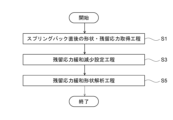
本発明の実施の形態に係るプレス成形品の形状変化予測方法は、一例として図2に示すように、天板部3と天板部3から連続する縦壁部5と縦壁部5から連続するフランジ部7とを有するハット型断面形状であり側面視で天板部3側に凸状に湾曲した形状を含むプレス成形品1について、金型から離型した瞬間にスプリングバックした後の時間経過に伴う応力緩和による形状変化を予測するものであって、図1に示すように、スプリングバック直後の形状・残留応力取得工程S1と、残留応力緩和減少設定工程S3と、残留応力緩和形状解析工程S5と、を備えるものである。以下、上記の各工程について説明する。
<Method for predicting shape change of press-formed product>
As shown in FIG. 2 as an example, the shape change prediction method of the press-formed product according to the embodiment of the present invention includes a
≪スプリングバック直後の形状・残留応力取得工程≫
スプリングバック直後の形状・残留応力取得工程S1は、プレス成形品1のスプリングバック解析により、スプリングバックした直後のプレス成形品1の形状及び残留応力を取得する工程である。
≪Shape and residual stress acquisition process immediately after springback≫
The shape and residual stress acquisition step S1 immediately after springback is a step of acquiring the shape and residual stress of the press-formed
スプリングバックした直後のプレス成形品1の形状及び残留応力を取得する具体的な処理の一例としては、実際のプレス成形品1のプレス成形に用いる金型をモデル化した金型モデルを用いて、金属板を成形下死点までプレス成形する過程のプレス成形解析を行い、成形下死点におけるプレス成形品1を求める第1段階と、該求めた成形下死点におけるプレス成形品1を金型モデルから離型した後のプレス成形品1の力のモーメントの釣り合いが取れる形状及び残留応力を求めるスプリングバック解析を行う第2段階と、を有する有限要素法によるプレス成形シミュレーションが挙げられる。
As an example of specific processing for acquiring the shape and residual stress of the press-formed
≪残留応力緩和減少設定工程≫
残留応力緩和減少設定工程S3は、スプリングバック直後の形状・残留応力取得工程S1において取得したスプリングバックした直後のプレス成形品1の少なくとも天板部3及び/又はフランジ部7に対し、その残留応力よりも緩和減少させた残留応力の値を設定する工程である。
<<Residual stress relaxation reduction setting process>>
In the residual stress relaxation reduction setting step S3, the residual stress is applied to at least the
残留応力緩和減少設定工程S3における残留応力とは、スプリングバックした直後のプレス成形品1に残留する引張応力及び圧縮応力のことをいう。
さらに、残留応力緩和減少設定工程S3において残留応力を緩和減少させた残留応力の値を設定するとは、スプリングバックした直後のプレス成形品1に残留する引張応力(正の値)及び圧縮応力(負の値)の絶対値を緩和減少させることをいう。
The residual stress in the residual stress relaxation reduction setting step S3 refers to the tensile stress and compressive stress remaining in the press-formed
Furthermore, setting the value of the residual stress after the residual stress is relaxed and reduced in the residual stress relaxation and reduction setting step S3 means that the tensile stress (positive value) and compressive stress (negative value) remaining in the press-formed
≪残留応力緩和形状解析工程≫
残留応力緩和形状解析工程S5は、残留応力緩和減少設定工程S3で残留応力を緩和減少設定したプレス成形品1について力のモーメントが釣り合う形状を求める解析を行う工程である。
<<Residual stress relaxation shape analysis process>>
The residual stress relaxation shape analysis step S5 is a step of performing an analysis for obtaining a shape in which the moment of force is balanced for the press-formed
残留応力緩和形状解析工程S5における解析には、スプリングバック直後の形状・残留応力取得工程S1におけるスプリングバック解析と同様の解析手法を適用することにより、残留応力を緩和減少した後のプレス成形品1の形状を得ることができる。
For the analysis in the residual stress relaxation shape analysis step S5, by applying the same analysis method as the springback analysis in the shape and residual stress acquisition step S1 immediately after springback, the press-formed
このように、本実施の形態に係るプレス成形品の形状変化予測方法によれば、スプリングバック解析により取得した、スプリングバックした直後のプレス成形品1の少なくとも天板部及び/又はフランジ部に対し、その残留応力よりも緩和減少した残留応力の値を設定し、該残留応力の値を緩和減少設定したプレス成形品1について力のモーメントと釣り合う形状を求める解析を行うことで、実際のプレス成形品1における時間経過による応力緩和と形状変化を模擬し、金型から離型してスプリングバックした後のプレス成形品1の時間経過に伴う形状変化(キャンバーバック)を予測することができる。
As described above, according to the press-formed product shape change prediction method according to the present embodiment, at least the top plate portion and/or the flange portion of the press-formed
なお、上記の説明において、残留応力緩和減少設定工程S3は、プレス成形品1における少なくとも天板部3及び/又はフランジ部7に対し、それら各部位の残留応力を緩和減少させた残留応力の値を設定するものであった。
In the above description, the residual stress relaxation and reduction setting step S3 is a residual stress value obtained by relaxing and reducing the residual stress of at least the
もっとも、本発明は、プレス成形品1における天板部3やフランジ部7以外の他の部位に対しても残留応力を緩和減少させるものであってもよいし、プレス成形品1の全部に対して残留応力を緩和減少させた値を設定してもよい。
さらには、天板部3やフランジ部7等の部位ごとに残留応力を緩和減少させる割合や値を変えてもよい。
However, according to the present invention, residual stress may be relieved and reduced in portions other than the
Furthermore, the rate or value for relaxing and reducing the residual stress may be changed for each portion such as the
また、上記の説明は、ハット型断面形状のプレス成形品1を対象としたものであったが、本発明は、天板部と該天板部から連続する縦壁部とを有し側面視で前記天板部側に凸状に湾曲した形状を含むプレス成形品であれば適用することができる。このようなプレス成形品としては、図5に例示するような天板部23と天板部23から連続する縦壁部25とを有してなるコ字型断面形状のプレス成形品21やL字型断面形状のプレス成形品(図示なし)、図6に例示するような、天板部33と天板部33から連続する縦壁部35と縦壁部35から連続するフランジ部37とを有してなるZ字型断面形状のプレス成形品31、等が挙げられる。
In addition, the above description is directed to the press-formed
なお、上記の説明は、長手方向の全長にわたって側面視で凸状に湾曲した形状のプレス成形品を対象とするものであったが、本発明は、側面視で凸状に湾曲した形状の部位を有するプレス成形品であればよく、例えば、湾曲した湾曲部と、該湾曲部の湾曲の端から長手方向の外方の両側又は片側に直線状に延出する辺部とを含むプレス成形品を対象とすることができる。 The above description is directed to a press-formed product having a shape that is convexly curved when viewed from the side over the entire length in the longitudinal direction. For example, a press-formed product that includes a curved portion and a side portion that extends linearly from the curved end of the curved portion to both sides or one side in the longitudinal direction can be targeted.
また、本発明は、残留応力緩和減少設定工程において、スプリングバックした直後の残留応力よりも5%以上緩和減少させることにより、時間経過した後の形状変化を良好に予測できて好ましい。 Further, in the present invention, in the residual stress relaxation reduction setting step, the residual stress immediately after springback is reduced by 5% or more, so that the shape change after the elapse of time can be predicted well, which is preferable.
なお、様々な形状のプレス成形品に本発明を適用し、残留応力を緩和減少させる割合を変化させて形状変化を予測したときの精度については、後述する実施例1~実施例4にて検証した。 It should be noted that the accuracy when the present invention is applied to press-formed products of various shapes and the shape change is predicted by changing the rate of relaxation and reduction of residual stress is verified in Examples 1 to 4 described later. bottom.
また、本発明に係るプレス成形品の形状変化予測方法において、プレス成形に供するブランク(金属板)や、プレス成形品の形状、種類には特に制限はないが、プレス成形品の残留応力が高くなる金属板を用いてプレス成形した自動車部品に対してより効果がある。 In addition, in the method for predicting shape change of a press-formed product according to the present invention, there is no particular limitation on the blank (metal plate) to be subjected to press-forming and the shape and type of the press-formed product, but the residual stress of the press-formed product is high. It is more effective for automobile parts press-formed using a metal plate of
具体的には、ブランクの板厚については、0.5mm以上4.0mm以上であることが好ましい。
また、ブランクの引張強度については、150MPa級以上2000MPa級以下であることが好ましく、440MPa級以上1470MPa級以下であることがより好ましい。
Specifically, the thickness of the blank is preferably 0.5 mm or more and 4.0 mm or more.
The tensile strength of the blank is preferably 150 MPa class or more and 2000 MPa class or less, more preferably 440 MPa class or more and 1470 MPa class or less.
引張強度が150MPa級未満の金属板は、プレス成形品に利用されることが少ないため、本発明に係るプレス成形品の形状変化予測方法を用いる利点が少ない。引張強度150MPa級以上の金属板を用いた自動車の外板部品等の剛性が低いものについては、残留応力の変化による形状変化を受けやすいため、本発明を適用する利点が多くなるので本発明を好適に適用できる。 Since metal sheets having a tensile strength of less than 150 MPa are rarely used for press-formed products, there is little advantage in using the press-formed product shape change prediction method according to the present invention. For parts with low rigidity such as automobile outer panel parts that use metal plates with a tensile strength of 150 MPa or more, they are susceptible to shape changes due to changes in residual stress. It can be applied suitably.
一方、引張強度が2000MPa級を超える金属板は延性が乏しいため、例えば、図2に示すようなハット型断面形状のプレス成形品1のプレス成形過程においてはパンチ肩部9やダイ肩部11で割れが発生しやすく、プレス成形することができない場合がある。
On the other hand, since a metal plate with a tensile strength exceeding 2000 MPa class has poor ductility, for example, in the press-forming process of a press-formed
さらに、プレス成形品の種類としては、フロントピラーアッパーやルーフレール等の骨格部品といった自動車部品を対象とすることが好ましいが、側面視で天板部側に凸状に湾曲した形状を含み、プレス成形した後の時間経過によりキャンバーバックが発生する自動車部品であれば本発明を広く用いることができる。 Furthermore, as the type of press-formed product, it is preferable to target automobile parts such as front pillar uppers and frame parts such as roof rails. The present invention can be widely used for automobile parts that cause camber back with the lapse of time.
なお、本発明で対象とするプレス成形品のプレス工法についても、曲げ成形、フォーム成形又はドロー成形等、特に問わない。 It should be noted that the press method for the press-formed product targeted by the present invention is not particularly limited, such as bending, form forming, or draw forming.
<ハット型断面形状のプレス成形品>
実施例1では、まず、金属板として以下の表1に一例を示す機械的特性を持つ鋼板Aを用い、図2に示す、側面視で凸状に湾曲したハット型断面形状のプレス成形品1のプレス成形を行った。プレス成形品1の成形下死点形状は、湾曲の曲率半径を170mm、プレス成形方向における縦壁部5の縦壁高さを40mmとした。
<Press molded product with hat-shaped cross section>
In Example 1, first, a steel plate A having mechanical properties shown in Table 1 below was used as a metal plate, and a press-formed

そして、成形下死点までプレス成形したプレス成形品1を金型から離型し、2日経過した後のプレス成形品1の形状を測定した。
Then, the press-molded
次に、プレス成形品1の形状変化を予測する解析を行った。
解析では、まず、プレス成形に用いる金型をモデル化した金型モデルを用いて、鋼板Aを成形下死点までプレス成形する過程のプレス成形解析を行い、成形下死点におけるプレス成形品1の残留応力を求めた。
Next, an analysis for predicting shape change of the press-formed
In the analysis, first, using a mold model that models the mold used for press forming, press forming analysis of the process of press forming steel plate A to the bottom dead point of forming is performed. The residual stress of
続いて、成形下死点におけるプレス成形品1を金型モデルから離型した直後のプレス成形品1の形状及び残留応力を求めるスプリングバック解析を行った。
Subsequently, a springback analysis was performed to determine the shape and residual stress of the press-formed
さらに、スプリングバック解析により求めた、スプリングバックした直後のプレス成形品1の天板部3及び/又はフランジ部7に対し、残留応力の絶対値を所定の割合低下させた残留応力の値を設定した。
そして、残留応力を低下させたプレス成形品1について力のモーメントが釣り合う形状を求める解析を行った。
Furthermore, a residual stress value obtained by reducing the absolute value of the residual stress by a predetermined percentage is set for the
Then, an analysis was performed to obtain a shape in which the moment of force is balanced for the press-formed
実施例1では、スプリングバック解析により取得したプレス成形品1の天板部、又は、天板部3及びフランジ部7に対し、スプリングバックした直後の残留応力を所定の割合(残留応力の緩和率)で低下した残留応力の値を設定したものを発明例1~発明例3とした。
In Example 1, the top plate portion of the press-formed
また、比較対象として、発明例1~発明例3と同様にプレス成形品1のプレス成形解析及びスプリングバック解析を行い、力のモーメントが釣り合う形状を求める解析を行わなかったものを比較例1、あるいは、スプリングバック解析を行った後、プレス成形品1に天板部3及びフランジ部7のいずれについても残留応力を低下させずに力のモーメントが釣り合う形状を求める解析を行ったものを比較例2とした。
In addition, as a comparison object, press forming analysis and springback analysis of the press-formed
発明例1~発明例3及び比較例1、比較例2のそれぞれについて、プレス成形品1の天板部3における長手方向先端(評価点a)における成形下死点でのプレス成形品1の形状からの成形高さ方向の乖離量を算出した。
表2に、発明例1~発明例3及び比較例1、比較例2において残留応力の緩和率と評価点aの乖離量の結果をまとめて示す。
For each of Invention Examples 1 to 3 and Comparative Examples 1 and 2, the shape of the press-formed
Table 2 summarizes the results of the relaxation rate of the residual stress and the deviation amount of the evaluation point a in Examples 1 to 3 and Comparative Examples 1 and 2.

表2において、予測値Dcは、発明例1~発明例3及び比較例1~比較例2における評価点aの乖離量、実験値Deは、実際にプレス成形したプレス成形品1の2日経過した後の評価点aの乖離量(=25.4mm)である。また、実験値に対する予測値の差分及び誤差は、それぞれ、下式により算出したものである。
実験値と予測値との差分(mm)=De-Dc ・・・(1)
予測値の誤差(%)=(De-Dc)÷De×100 ・・・(2)
In Table 2, the predicted value D c is the deviation amount of the evaluation point a in Invention Examples 1 to 3 and Comparative Examples 1 to 2, and the experimental value D e is actually press-molded press-molded product 1-2. This is the deviation amount (=25.4 mm) of the evaluation point a after the passage of days. Moreover, the difference and the error of the predicted value with respect to the experimental value are calculated by the following formulas.
Difference between experimental value and predicted value (mm) = D e - D c (1)
Error of predicted value (%) = (D e - D c ) ÷ D e × 100 (2)
比較例1と比較例2における評価点aの乖離量は等しく、実験値と予測値との差分は3.5mm、予測値の誤差は13.8%であった。 The difference between the evaluation point a in Comparative Example 1 and Comparative Example 2 was the same, the difference between the experimental value and the predicted value was 3.5 mm, and the error in the predicted value was 13.8%.
発明例1は、天板部3に対して残留応力を5%低下させた残留応力の値を設定したものであり、実験値と予測値との差分は1.5mm、予測値の誤差は5.9%となり、比較例1及び比較例2と比べて改善した。
発明例2は、天板部3及び縦壁部5に対してそれらの残留応力をそれぞれ10%低下させた残留応力の値を設定したものであり、実験値と予測値との差分は0.3mm、予測値の誤差は1.2%となり、比較例1及び比較例2と比べて改善し、発明例1よりも良好な結果であった。
発明例3は、天板部3及び縦壁部5に対してそれらの残留応力をそれぞれ20%低下させた残留応力の値を設定したものであり、実験値と予測値との差分は-0.4mm、予測値の誤差は-1.6%となり、いずれも負の値であるが、絶対値で比較すると比較例1及び比較例2と比べて改善した。
In invention example 1, the value of the residual stress is set by reducing the residual stress by 5% with respect to the
In Invention Example 2, the residual stress values of the
In invention example 3, the residual stress values of the
<コ字型断面形状のプレス成形品>
実施例2では、まず、前述した実施例1と同様に表1に示す機械的特性を持つ鋼板Aを用い、図5に示すコ字型断面形状のプレス成形品21をプレス成形した。プレス成形品21は、天板部23と天板部23から連続する縦壁部25とを有してなるコ字型断面形状であり、側面視で天板部23側に凸状に湾曲している。そして、プレス成形品21は、成形下死点において湾曲の曲率半径が170mm、プレス成形方向における縦壁部25の縦壁高さが35mmである。
<Press molded product with U-shaped cross section>
In Example 2, steel plate A having the mechanical properties shown in Table 1 was first press-formed into a press-formed
続いて、成形下死点までプレス成形したプレス成形品21を金型から離型し、2日経過した後のプレス成形品21の形状を測定した。
Subsequently, the press-molded
次に、プレス成形品21のプレス成形解析とこれに続くスプリングバック解析を行い、さらに、スプリングバック直後のプレス成形品21における天板部23に対して所定の割合で残留応力を緩和減少させた残留応力の値を設定し、プレス成形品21について力のモーメントが釣り合う形状を求める解析を行ったものを発明例4及び発明例5とした。
Next, the press-formed analysis of the press-formed
また、比較対象として、発明例4及び発明例5と同様にプレス成形品21のプレス成形解析及びスプリングバック解析を行ったものの、残留応力を緩和減少した値を設定して力のモーメントが釣り合う形状を求める解析を行わなかったものを比較例3とした。
In addition, as a comparison target, press forming analysis and springback analysis of the press formed
そして、発明例4、発明例5及び比較例3それぞれについて、プレス成形品21の天板部23における長手方向の先端(評価点b)における成形下死点でのプレス成形品21の形状からの成形高さ方向の乖離量を算出した。
表3に、発明例4、発明例5及び比較例3において残留応力の緩和率と評価点bの乖離量の結果をまとめて示す。
Then, for each of Invention Example 4, Invention Example 5, and Comparative Example 3, the shape of the press-formed
Table 3 summarizes the results of the relaxation rate of the residual stress and the amount of divergence between the evaluation point b in Inventive Examples 4, 5 and Comparative Example 3.

表3において、予測値Dcは、発明例4、発明例5及び比較例4における評価点bの乖離量、実験値Deは、実際にプレス成形したプレス成形品21の2日経過した後の評価点bの乖離量(=26.4mm)である。また、実験値と予測値との差分及び実験値に対する予測値の誤差は、それぞれ、前述した式(1)及び(2)により算出したものである。
In Table 3, the predicted value D c is the deviation amount of the evaluation point b in Invention Examples 4, 5, and Comparative Example 4, and the experimental value D e is the actually press-molded press-molded
比較例3は、実験値と予測値との差分は2.6mm、予測値の誤差は9.8%であった。
発明例4は、天板部23に対して残留応力を5%低下させたものであり、実験値と予測値との差分は1.2mm、予測値の誤差は4.5%であり、比較例4と比べて改善した。
発明例5は、天板部23に対して残留応力を10%低下させたものであり、実験値と予測値との差分は0.3mm、予測値の誤差は1.1%であり、比較例4と比べて改善し、発明例4よりも良好であった。
In Comparative Example 3, the difference between the experimental value and the predicted value was 2.6 mm, and the error of the predicted value was 9.8%.
In Invention Example 4, the residual stress was reduced by 5% with respect to the
In Invention Example 5, the residual stress was reduced by 10% with respect to the
<Z字型断面形状のプレス成形品>
実施例3では、まず、前述した実施例1と同様に表1に示す機械的特性を持つ鋼板Aを用い、図6に示すプレス成形品31をプレス成形した。
プレス成形品31は、天板部33と天板部33から連続する縦壁部35と縦壁部35から連続するフランジ部37とを有してなるZ字型断面形状であり、側面視で天板部33側に凸状に湾曲している。そして、プレス成形品31は、成形下死点において湾曲の曲率半径が170mm、プレス成形方向における縦壁部35の縦壁高さが40mmである。
<Press molded product with Z-shaped cross section>
In Example 3, a press-formed
The press-formed
続いて、成形下死点までプレス成形したプレス成形品31を金型から離型し、2日経過した後のプレス成形品31の形状変化を測定した。
Subsequently, the press-molded
次に、プレス成形品31のプレス成形解析とこれに続くスプリングバック解析を行い、さらに、スプリングバック直後のプレス成形品31における天板部33及びフランジ部37に対してそれらの残留応力を緩和減少させた残留応力の値を設定し、プレス成形品31について力のモーメントが釣り合う形状を求める解析を行ったものを発明例6及び発明例7とした。
また、比較対象として、発明例6及び発明例7と同様にプレス成形品31のプレス成形解析及びスプリングバック解析を行ったものの、残留応力を緩和減少した値を設定して力のモーメントが釣り合う形状を求める解析を行わなかったものを比較例4とした。
Next, the press forming analysis of the press formed
In addition, as a comparison target, press forming analysis and springback analysis of the press-formed
そして、発明例6、発明例7及び比較例4それぞれについて、プレス成形品31の天板部33における長手方向の先端(評価点c)における成形下死点でのプレス成形品31の形状からの成形高さ方向の乖離量を算出した。
表4に、発明例6、発明例7及び比較例4において残留応力の緩和率と評価点cの乖離量の結果をまとめて示す。
Then, for each of Invention Example 6, Invention Example 7, and Comparative Example 4, from the shape of the press-formed
Table 4 summarizes the results of the relaxation rate of the residual stress and the amount of deviation between the evaluation points c in Invention Examples 6, 7 and Comparative Example 4.

表4において、予測値Dcは、発明例6、発明例7及び比較例4における評価点cの乖離量、実験値Deは、実際にプレス成形したプレス成形品31の2日経過した後の評価点dの乖離量(=26.5mm)である。また、実験値に対する予測値の差分及び誤差は、それぞれ、前述した式(1)及び(2)により算出したものである。
In Table 4, the predicted value D c is the deviation amount of the evaluation points c in Invention Examples 6, 7 and Comparative Example 4, and the experimental value D e is the actually press-molded press-molded
比較例4は、実験値と予測値との差分は2.5mm、予測値の誤差は9.4%であった。
発明例6は、天板部33に対し、その残留応力を5%低下させたものであり、実験値との差分は1.0mm、予測値の誤差は3.8%であり、比較例4と比べて改善した。
発明例7は、天板部33及びフランジ部37の双方に対し、それぞれの残留応力を10%低下させたものであり、実験値と予測値との差分は-0.4mm、予測値の誤差は-1.5%であり、いずれも負の値であるが、絶対値で比較すると比較例4と比べて改善し、発明例6よりも良好であった。
In Comparative Example 4, the difference between the experimental value and the predicted value was 2.5 mm, and the error of the predicted value was 9.4%.
In Invention Example 6, the residual stress of the
In Invention Example 7, the residual stress of both the
<フロントピラーアッパー>
実施例4では、まず、前述した実施例1と同様に表1に示す機械的特性を持つ鋼板Aを用い、図7に示す自動車のフロントピラーアッパーであるプレス成形品41をプレス成形した。プレス成形品41は、天板部43と縦壁部45とフランジ部47とを有するハット型断面形状であり、側面視で天板部43側に凸状に湾曲した形状を含む。そして、プレス成形品41は、成形下死点における湾曲の曲率半径が1000mm、プレス成形方向における縦壁部45の縦壁高さが45mmである。
<Front pillar upper>
In Example 4, steel plate A having the mechanical properties shown in Table 1 was first used in the same manner as in Example 1 described above to press-form a press-formed
続いて、成形下死点までプレス成形したプレス成形品41を金型から離型し、2日経過した後のプレス成形品41の形状変化を測定した。
Subsequently, the press-molded
次に、プレス成形品41のプレス成形解析とこれに続くスプリングバック解析を行い、さらに、スプリングバック直後のプレス成形品41における天板部43及びフランジ部47に対してそれぞれの残留応力を緩和減少させた残留応力の値を設定し、プレス成形品41について力のモーメントが釣り合う形状を求める解析を行ったものを発明例8及び発明例9とした。
また、比較対象として、発明例8及び発明例9と同様にプレス成形品41のプレス成形解析及びスプリングバック解析を行ったものの、残留応力を緩和減少した値を設定して力のモーメントが釣り合う形状を求める解析を行わなかったものを比較例5とした。
Next, the press forming analysis of the press formed
In addition, as a comparison target, press forming analysis and springback analysis of the press formed
そして、発明例8、発明例9及び比較例5それぞれについて、プレス成形品41の天板部43における長手方向の先端(評価点d)における成形下死点形状からの成形高さ方向の乖離量を算出した。
表5に、発明例8、発明例9及び比較例5において残留応力の緩和率と評価点dの乖離量の結果をまとめて示す。
Then, for each of Invention Example 8, Invention Example 9, and Comparative Example 5, the amount of deviation in the molding height direction from the molding bottom dead center shape at the longitudinal end (evaluation point d) of the
Table 5 summarizes the results of the difference between the residual stress relaxation rate and the evaluation point d in Inventive Examples 8, 9 and Comparative Example 5.

表5において、予測値Dcは、発明例8及び比較例9における評価点dの乖離量、実験値Deは、実際にプレス成形したプレス成形品41の2日経過した後の評価点dの乖離量(=22.5mm)である。また、実験値と予測値との差分及び実験値に対する予測値の誤差は、それぞれ、前述した式(1)及び(2)により算出したものである。
In Table 5, the predicted value D c is the deviation amount of the evaluation point d in Invention Example 8 and Comparative Example 9, and the experimental value D e is the evaluation point d after two days of the actually press-molded press-molded
比較例5は、実験値と予測値との差分は2.2mm、予測値の誤差は9.8%であった。
発明例8は、天板部43に対し、その残留応力を5%低下させたものであり、実験値と予測値との差分は1.0mm、予測値の誤差は4.4%であり、比較例5と比べて改善した。
発明例9は、天板部43及びフランジ部47の双方に対し、それぞれ残留応力を10%低下させたものであり、実験値と予測値との差分は0.3mm、予測値の誤差は1.3%であり、比較例5と比べて改善し、発明例8よりも良好であった。
In Comparative Example 5, the difference between the experimental value and the predicted value was 2.2 mm, and the error of the predicted value was 9.8%.
In Invention Example 8, the residual stress of the
In Example 9, the residual stress of both the
1 プレス成形品
3 天板部
5 縦壁部
7 フランジ部
9 パンチ肩部
11 ダイ肩部
21 プレス成形品
23 天板部
25 縦壁部
31 プレス成形品
33 天板部
35 縦壁部
37 フランジ部
41 プレス成形品
43 天板部
45 縦壁部
47 フランジ部
1 press-formed
Claims (3)
前記プレス成形品のスプリングバック解析により、スプリングバックした直後の前記プレス成形品の形状及び残留応力を取得するスプリングバック直後の形状・残留応力取得工程と、
スプリングバックした直後の前記プレス成形品の少なくとも前記天板部に対し、スプリングバックした直後の残留応力よりも絶対値が5%~20%緩和減少した残留応力の値を設定する残留応力緩和減少設定工程と、
残留応力の値を緩和減少設定した前記プレス成形品について力のモーメントが釣り合う形状を求める残留応力緩和形状解析工程と、を含むことを特徴とするプレス成形品の形状変化予測方法。 For a press-formed product having a top plate portion and a vertical wall portion continuous from the top plate portion and including a convexly curved shape toward the top plate portion side in a side view, a spring is formed at the moment the mold is released from the mold. A shape change prediction method for a press-formed product for predicting shape change due to stress relaxation over time after backing,
A shape and residual stress acquisition step immediately after springback for acquiring the shape and residual stress of the press-formed product immediately after springback by springback analysis of the press-formed product;
Residual stress relaxation reduction setting for setting a residual stress value that is reduced by 5% to 20% in absolute value from the residual stress immediately after springback for at least the top plate portion of the press-formed product immediately after springback. process and
and a residual stress relaxation shape analysis step of obtaining a shape in which the moment of force is balanced for the press-formed product in which the value of the residual stress is set to be relaxed and decreased.
前記プレス成形品のスプリングバック解析により、スプリングバックした直後の前記プレス成形品の形状及び残留応力を取得するスプリングバック直後の形状・残留応力取得工程と、
スプリングバックした直後の前記プレス成形品の少なくとも前記天板部及び/又は前記フランジ部に対し、スプリングバックした直後の残留応力よりも絶対値が5%~20%緩和減少した残留応力の値を設定する残留応力緩和減少設定工程と、
残留応力の値を緩和減少設定した前記プレス成形品について力のモーメントが釣り合う形状を求める残留応力緩和形状解析工程と、を含むことを特徴とするプレス成形品の形状変化予測方法。 A press-formed product having a top plate portion, a vertical wall portion continuing from the top plate portion, and a flange portion continuing from the vertical wall portion, and including a shape that is convexly curved toward the top plate portion in a side view , A shape change prediction method for a press-formed product that predicts shape change due to stress relaxation over time after springback at the moment the mold is released from the mold,
A shape and residual stress acquisition step immediately after springback for acquiring the shape and residual stress of the press-formed product immediately after springback by springback analysis of the press-formed product;
For at least the top plate portion and/or the flange portion of the press-formed product immediately after springback, set a value of residual stress that is 5% to 20% less in absolute value than the residual stress immediately after springback. a residual stress relaxation reduction setting step for
and a residual stress relaxation shape analysis step of obtaining a shape in which the moment of force is balanced for the press-formed product in which the value of the residual stress is set to be relaxed and decreased.
Priority Applications (1)
| Application Number | Priority Date | Filing Date | Title |
|---|---|---|---|
| JP2020124218A JP7298564B2 (en) | 2020-07-21 | 2020-07-21 | Shape change prediction method for press-formed products |
Applications Claiming Priority (1)
| Application Number | Priority Date | Filing Date | Title |
|---|---|---|---|
| JP2020124218A JP7298564B2 (en) | 2020-07-21 | 2020-07-21 | Shape change prediction method for press-formed products |
Publications (2)
| Publication Number | Publication Date |
|---|---|
| JP2022020932A JP2022020932A (en) | 2022-02-02 |
| JP7298564B2 true JP7298564B2 (en) | 2023-06-27 |
Family
ID=80220084
Family Applications (1)
| Application Number | Title | Priority Date | Filing Date |
|---|---|---|---|
| JP2020124218A Active JP7298564B2 (en) | 2020-07-21 | 2020-07-21 | Shape change prediction method for press-formed products |
Country Status (1)
| Country | Link |
|---|---|
| JP (1) | JP7298564B2 (en) |
Citations (4)
| Publication number | Priority date | Publication date | Assignee | Title |
|---|---|---|---|---|
| JP2006315063A (en) | 2005-05-16 | 2006-11-24 | M & M Research:Kk | Die design support program and method for press working |
| JP2020028888A (en) | 2018-08-21 | 2020-02-27 | Jfeスチール株式会社 | Press molding method |
| WO2020126380A1 (en) | 2018-12-21 | 2020-06-25 | Bystronic Laser Ag | Bending machine, machining line and method for bending |
| JP2022026451A (en) | 2020-07-31 | 2022-02-10 | Jfeスチール株式会社 | Shape change prediction method of press-formed product |
-
2020
- 2020-07-21 JP JP2020124218A patent/JP7298564B2/en active Active
Patent Citations (4)
| Publication number | Priority date | Publication date | Assignee | Title |
|---|---|---|---|---|
| JP2006315063A (en) | 2005-05-16 | 2006-11-24 | M & M Research:Kk | Die design support program and method for press working |
| JP2020028888A (en) | 2018-08-21 | 2020-02-27 | Jfeスチール株式会社 | Press molding method |
| WO2020126380A1 (en) | 2018-12-21 | 2020-06-25 | Bystronic Laser Ag | Bending machine, machining line and method for bending |
| JP2022026451A (en) | 2020-07-31 | 2022-02-10 | Jfeスチール株式会社 | Shape change prediction method of press-formed product |
Also Published As
| Publication number | Publication date |
|---|---|
| JP2022020932A (en) | 2022-02-02 |
Similar Documents
| Publication | Publication Date | Title |
|---|---|---|
| JP7243657B2 (en) | Shape change prediction method for press-formed products | |
| JP7021696B1 (en) | Method for predicting shape change of press-molded products | |
| RU2692353C1 (en) | Production method of pressed products and production line for them | |
| KR102915850B1 (en) | Shape change prediction method for press formed part | |
| JP6977824B1 (en) | Method for predicting shape change of press-molded products | |
| JP6939962B1 (en) | Method for predicting shape change of press-molded products | |
| JP7342921B2 (en) | Method for predicting shape change of press-formed products | |
| JP7151736B2 (en) | Shape change prediction method for press-formed products | |
| JP7298564B2 (en) | Shape change prediction method for press-formed products | |
| WO2021171678A1 (en) | Press forming method and shape evaluation method for press formed article | |
| JP6973580B1 (en) | Method for predicting shape change of press-molded products | |
| JP6977838B1 (en) | Method for predicting shape change of press-molded products | |
| JP6977825B1 (en) | Method for predicting shape change of press-molded products | |
| JP2025134112A (en) | Press forming analysis method and press forming product manufacturing method |
Legal Events
| Date | Code | Title | Description |
|---|---|---|---|
| A621 | Written request for application examination |
Free format text: JAPANESE INTERMEDIATE CODE: A621 Effective date: 20220222 |
|
| A977 | Report on retrieval |
Free format text: JAPANESE INTERMEDIATE CODE: A971007 Effective date: 20221118 |
|
| A131 | Notification of reasons for refusal |
Free format text: JAPANESE INTERMEDIATE CODE: A131 Effective date: 20221129 |
|
| A521 | Request for written amendment filed |
Free format text: JAPANESE INTERMEDIATE CODE: A523 Effective date: 20230113 |
|
| TRDD | Decision of grant or rejection written | ||
| A01 | Written decision to grant a patent or to grant a registration (utility model) |
Free format text: JAPANESE INTERMEDIATE CODE: A01 Effective date: 20230516 |
|
| A61 | First payment of annual fees (during grant procedure) |
Free format text: JAPANESE INTERMEDIATE CODE: A61 Effective date: 20230529 |
|
| R150 | Certificate of patent or registration of utility model |
Ref document number: 7298564 Country of ref document: JP Free format text: JAPANESE INTERMEDIATE CODE: R150 |