JP7296733B2 - Motor control device and image forming device - Google Patents
Motor control device and image forming device Download PDFInfo
- Publication number
- JP7296733B2 JP7296733B2 JP2019008599A JP2019008599A JP7296733B2 JP 7296733 B2 JP7296733 B2 JP 7296733B2 JP 2019008599 A JP2019008599 A JP 2019008599A JP 2019008599 A JP2019008599 A JP 2019008599A JP 7296733 B2 JP7296733 B2 JP 7296733B2
- Authority
- JP
- Japan
- Prior art keywords
- excitation
- phase
- rotor
- excited
- phases
- Prior art date
- Legal status (The legal status is an assumption and is not a legal conclusion. Google has not performed a legal analysis and makes no representation as to the accuracy of the status listed.)
- Active
Links
Images


Classifications
-
- H—ELECTRICITY
- H02—GENERATION; CONVERSION OR DISTRIBUTION OF ELECTRIC POWER
- H02P—CONTROL OR REGULATION OF ELECTRIC MOTORS, ELECTRIC GENERATORS OR DYNAMO-ELECTRIC CONVERTERS; CONTROLLING TRANSFORMERS, REACTORS OR CHOKE COILS
- H02P6/00—Arrangements for controlling synchronous motors or other dynamo-electric motors using electronic commutation dependent on the rotor position; Electronic commutators therefor
- H02P6/14—Electronic commutators
- H02P6/16—Circuit arrangements for detecting position
- H02P6/18—Circuit arrangements for detecting position without separate position detecting elements
- H02P6/185—Circuit arrangements for detecting position without separate position detecting elements using inductance sensing, e.g. pulse excitation
-
- G—PHYSICS
- G03—PHOTOGRAPHY; CINEMATOGRAPHY; ANALOGOUS TECHNIQUES USING WAVES OTHER THAN OPTICAL WAVES; ELECTROGRAPHY; HOLOGRAPHY
- G03G—ELECTROGRAPHY; ELECTROPHOTOGRAPHY; MAGNETOGRAPHY
- G03G15/00—Apparatus for electrographic processes using a charge pattern
- G03G15/50—Machine control of apparatus for electrographic processes using a charge pattern, e.g. regulating differents parts of the machine, multimode copiers, microprocessor control
- G03G15/5004—Power supply control, e.g. power-saving mode, automatic power turn-off
-
- G—PHYSICS
- G03—PHOTOGRAPHY; CINEMATOGRAPHY; ANALOGOUS TECHNIQUES USING WAVES OTHER THAN OPTICAL WAVES; ELECTROGRAPHY; HOLOGRAPHY
- G03G—ELECTROGRAPHY; ELECTROPHOTOGRAPHY; MAGNETOGRAPHY
- G03G15/00—Apparatus for electrographic processes using a charge pattern
- G03G15/50—Machine control of apparatus for electrographic processes using a charge pattern, e.g. regulating differents parts of the machine, multimode copiers, microprocessor control
- G03G15/5008—Driving control for rotary photosensitive medium, e.g. speed control, stop position control
-
- G—PHYSICS
- G03—PHOTOGRAPHY; CINEMATOGRAPHY; ANALOGOUS TECHNIQUES USING WAVES OTHER THAN OPTICAL WAVES; ELECTROGRAPHY; HOLOGRAPHY
- G03G—ELECTROGRAPHY; ELECTROPHOTOGRAPHY; MAGNETOGRAPHY
- G03G15/00—Apparatus for electrographic processes using a charge pattern
- G03G15/80—Details relating to power supplies, circuits boards, electrical connections
Landscapes
- Engineering & Computer Science (AREA)
- Physics & Mathematics (AREA)
- General Physics & Mathematics (AREA)
- Microelectronics & Electronic Packaging (AREA)
- Power Engineering (AREA)
- Control Of Motors That Do Not Use Commutators (AREA)
- Control Or Security For Electrophotography (AREA)
- Controlling Sheets Or Webs (AREA)
- Delivering By Means Of Belts And Rollers (AREA)
Description
本発明は、モータの制御技術に関する。 The present invention relates to motor control technology.
画像形成装置の回転部材の駆動源の一つとして用いられるDCブラシレスモータには、特許文献1に記載されている様に、ロータ位置を検出するためのホール素子を有さないセンサレス型のものがある。モータの起動処理においては、起動時の脱調や逆回転を防ぐため、ロータの停止位置(以下、ロータ停止位置と呼ぶ。)に応じた処理が行われる。このため、センサレス型モータの起動処理においては、ロータ停止位置の検知が行われる。特許文献2は、コイルに電圧を短時間印加したときの励磁電流に基づきロータ停止位置を検知する構成を開示している。 DC brushless motors used as one of the drive sources for rotating members of image forming apparatuses include sensorless motors that do not have Hall elements for detecting the rotor position, as described in Patent Document 1. be. In the motor start-up process, a process is performed according to the stop position of the rotor (hereinafter referred to as rotor stop position) in order to prevent step-out and reverse rotation at start-up. Therefore, detection of the rotor stop position is performed in the start-up process of the sensorless type motor. Patent Document 2 discloses a configuration for detecting a rotor stop position based on an exciting current when a voltage is applied to a coil for a short period of time.
具体的には、特許文献2は、3相(U、V、W)のコイルの内の2つのコイルの順列である6つの励磁相を順に励磁することで、ロータ停止位置の検知を行うことを開示している。この様に、特許文献2の構成では、ロータ停止位置の検知のために、総ての励磁相を順に励磁する必要があり、ロータ停止位置の検知に要する時間が長くなる。 Specifically, Patent Document 2 discloses that the rotor stop position is detected by sequentially exciting six excitation phases, which are the permutation of two coils out of three-phase (U, V, W) coils. is disclosed. As described above, in the configuration of Patent Document 2, it is necessary to sequentially excite all the excitation phases in order to detect the rotor stop position, which increases the time required to detect the rotor stop position.
本発明は、ロータ停止位置の検知に要する時間を短くする技術を提供するものである。 The present invention provides a technique for shortening the time required to detect the rotor stop position.
本発明の一態様によると、モータ制御装置は、モータの複数の励磁相を励磁する励磁手段と、前記複数の励磁相を構成する複数のコイルの少なくとも1つのコイルのインダクタンスに応じて変化する物理量を、前記複数の励磁相それぞれを励磁した際に測定する測定手段と、前記励磁手段を制御する制御手段と、を備え、前記複数の励磁相は、それぞれ、前記複数のコイルの内の2つのコイルの順列で識別され、前記測定手段は、第1コイル、第2コイルの順で識別される励磁相を励磁して当該励磁相の前記物理量を測定するために、第1期間においては前記第1コイルに電圧を印可し、前記第1期間に続く第2期間においては前記第2コイルに電圧を印可し、前記制御手段は、前記モータのロータの停止位置を判定する期間において、前記複数の励磁相を順番に励磁し、前記複数の励磁相それぞれを励磁した際に前記測定手段によって測定された測定値と第1閾値とを順番順に比較することで前記モータの前記ロータの前記停止位置を判定し、前記モータの前記ロータの前記停止位置を判定すると、前記制御手段は、前記複数の励磁相の残りの励磁相を励磁しないことを特徴とする。
According to one aspect of the present invention, a motor control device comprises: excitation means for exciting a plurality of excitation phases of a motor; and measuring means for measuring when each of the plurality of excitation phases is excited, and control means for controlling the excitation means, wherein the plurality of excitation phases are respectively measured by two of the plurality of coils The measurement means excites the excitation phases identified by the order of the coils, and the excitation phases identified in the order of the first coil and the second coil, and measures the physical quantity of the excitation phases. A voltage is applied to one coil, a voltage is applied to the second coil in a second period following the first period, and the control means controls the plurality of coils during the period for determining the stop position of the rotor of the motor. The stop position of the rotor of the motor is determined by sequentially exciting the excitation phases and sequentially comparing the measured values measured by the measuring means when each of the plurality of excitation phases is excited with the first threshold value. and determining the stop position of the rotor of the motor, the control means does not excite the remaining excitation phases of the plurality of excitation phases.
本発明によると、ロータ停止位置の検知に要する時間を短くすることができる。 According to the present invention, the time required to detect the rotor stop position can be shortened.
以下、添付図面を参照して実施形態を詳しく説明する。尚、以下の実施形態は特許請求の範囲に係る発明を限定するものでするものでない。実施形態には複数の特徴が記載されているが、これらの複数の特徴の全てが発明に必須のものとは限らず、また、複数の特徴は任意に組み合わせられてもよい。さらに、添付図面においては、同一若しくは同様の構成に同一の参照番号を付し、重複した説明は省略する。 Hereinafter, embodiments will be described in detail with reference to the accompanying drawings. In addition, the following embodiments are not intended to limit the invention according to the claims. Although multiple features are described in the embodiments, not all of these multiple features are essential to the invention, and multiple features may be combined arbitrarily. Furthermore, in the accompanying drawings, the same or similar configurations are denoted by the same reference numerals, and redundant description is omitted.
<第一実施形態>
図1は、プリンタ、複写機、複合機、ファクシミリといった、本実施形態による、画像形成装置10を示している。画像形成装置10は、イエロー(Y)、マゼンタ(M)、シアン(C)、ブラック(K)の4色のトナー像を重ね合わせてフルカラーの画像を形成する。図1において、参照符号の末尾のY、M、C及びKは、参照符号により示される部材が形成に関わるトナー像の色が、それぞれ、イエロー、マゼンタ、シアン及びブラックであることを示している。なお、以下の説明において、色を区別する必要がない場合には、末尾のY、M、C及びKを除いた参照符号を使用する。感光体11は、画像形成時、図の時計回り方向に回転駆動される。帯電部12は、感光体11の表面を一様な電位に帯電させる。露光部13は、感光体11の表面を光で露光して感光体11に静電潜像を形成する。現像部の現像ローラ15は、現像バイアスを出力することで、感光体11の静電潜像をトナーで現像してトナー像として可視化する。一次転写部16は、一次転写バイアスにより、感光体11に形成されたトナー像を中間転写ベルト17に転写する。なお、各感光体11に形成されたトナー像を中間転写ベルト17に重ねて転写することでフルカラーの画像が中間転写ベルト17に形成される。
<First embodiment>
FIG. 1 shows an
中間転写ベルト17は、駆動ローラ20により図の反時計回り方向に回転駆動される。これにより中間転写ベルト17に転写されたトナー像は、二次転写部19の対向位置へと搬送される。一方、カセット21に格納された記録材(シート)Pは、搬送路23に沿って搬送され、二次転写部19の対向位置へと搬送される。搬送路23には、記録材Pを搬送するためのローラが設けられている。二次転写部19は、二次転写バイアスにより中間転写ベルト17のトナー像を記録材Pに転写する。その後、記録材Pは、定着器24へと搬送される。定着器24は、記録材Pを加熱・加圧してトナー像を記録材Pに定着させる。トナー像の定着後、記録材Pは、画像形成装置の外部に排出される。モータ151は、不図示のギア機構を介して感光体11、帯電部12、現像ローラ15、一次転写部16及び駆動ローラ20を回転させる。
The
図2は、画像形成装置の制御構成を示している。制御部40は、通信コントローラ210を介してホストコンピュータ220から形成する画像の画像データを受信すると画像形成を開始する。制御部40は、画像形成を開始すると、モータ制御部41を制御して、モータ151を含む各モータ150を回転駆動し、感光体11等の回転部材の回転駆動制御や、記録材Pの搬送制御等を行う。また、制御部40は、露光部13を制御して感光体11に静電潜像を形成する。また、制御部40は、定着器24を制御して記録材Pにトナー像を定着させる。制御部40は、表示部200に画像形成装置の状態を表示する。なお、制御部40は、マイクロコンピュータ及びメモリを有する。メモリは、各種制御プログラムやデータを保持しており、マイクロコンピュータは、メモリに格納されている各種制御プログラムやデータ等に基づき画像形成装置10の各部を制御する。
FIG. 2 shows the control configuration of the image forming apparatus. When receiving image data of an image to be formed from the
続いて、モータ151を制御するモータ制御部41の構成について図3を用いて説明する。モータ制御部41は、例えば、マイコン等で実現する処理部51を備えている。通信ポート52は、制御部40とシリアルデータ通信を行う。カウンタ54は、基準クロック生成部56が水晶発振子50を使用して生成した基準クロックに基づきカウント動作を行う。カウンタ54によるカウント値は、入力されたパルスの周期の計測や、時間の管理を行うために使用される。不揮発メモリ55は、処理部51がその処理に使用するデータ等を保持する保持部である。パルス幅変調(PWM)ポート58は、3相インバータ60の各スイッチング素子を駆動するためのPWM信号を出力する。3相インバータ60のスイッチング素子は、例えば、FETであり、PWM信号により駆動されることで、モータ151の複数のコイル73(U相)、74(V相)及び75(W相)に励磁のための電流を供給する。このように、3相インバータ60は、モータ151を励磁する励磁部として動作する。また、各コイル73、74、75の励磁電流は、抵抗63で電圧に変換され、処理部51のADコンバータ53に、励磁電流を示す電圧値として入力される。ADコンバータ53は、入力される電圧値(アナログ値)をデジタル値に変換する。処理部51は、ADコンバータ53が出力するデジタル値に基づき励磁電流の値を判定する。この様に、抵抗63、ADコンバータ53及び処理部51は、励磁電流を測定する測定部として動作する。また、モータ制御部41のコンパレータ64は、各コイル73、74、75が共に接続される接続点である中性点76と、各コイル73、74、75の他端の電圧とを比較して比較結果を処理部51の割り込みポート57に出力する。つまり、コンパレータ64は、各コイル73、74、75の誘起電圧の方向を示す信号を処理部51に出力する。なお、コンパレータ64の入力部分には、適宜、フィルタを設けることができる。また、コンパレータ64を使用するのではなく、処理部51において、各コイル73、74、75の両端の電圧を比較しても良い。
Next, the configuration of the
モータ151の構造について図4を用いて説明する。モータ151は、6スロットのステータ71と、4極のロータ72を有し、ステータ71には3相(U、V、W)の各コイル73、74、75が設けられている。ロータ72は、永久磁石により構成され、N極とS極をそれぞれ2つ有する。ロータ72の回転位置は、励磁されているコイル73、74、75の組み合わせ、つまり励磁相によって決まる。なお、本実施形態では、X-Y相を励磁すると、X相のコイルからY相のコイルに向けて励磁電流が流れ、このとき、X相のコイルがN極となり、Y相のコイルがS極となるものとする。したがって、U-V相を励磁すると、ロータ72は、図4(A)に示す位置で停止する。U-W相を励磁すると、ロータ72は、図4(B)に示す位置で停止する。以下、X-Y相を励磁した場合にロータ72が停止する位置を、X-Y相の位置と表現する。図4(A)~(F)は、それぞれ、U-V相、U-W相、V-W相、V-U相、W-U相、W-V相を励磁し、よって、ロータ72が対応する励磁相の位置で停止している状態を示している。
A structure of the
なお、ロータ72を回転させる場合、処理部51は、ロータ72の回転方向に応じて、図4の右回り又は左回り方向に沿って順に励磁する。例えば、図4の右回りの場合、U-V相、U-W相、V-W相、V-U相、W-U相、W-V相、U-V相、・・・の順で励磁を繰り返す。以下、この励磁の順序において、ある励磁相に隣接する2つの励磁相を、当該励磁相の隣接励磁相と表現する。同様に、ある励磁相を励磁した際のロータ72の停止位置に対し、当該励磁相の隣接励磁相を励磁した際のロータ72の停止位置を隣接位置と表現する。例えば、W-V相の位置と、U-W相の位置は、それぞれ、U-V相の隣接位置である。
When rotating the
一般的に、コイルは電磁鋼板を積層したコアに銅線を巻いた構成となっている。また、電磁鋼板の透磁率は外部磁界が有る場合には小さくなり、透磁率に比例するコイルのインダクタンスも小さくなる。例えば、図4(A)に示す様に、U相のコイル73の対向位置に、ロータ72のS極のみが対向する様にロータ72が停止しているものとする。この場合、ロータ72による外部磁界の影響が大きいため、コイル73のインダクタンスの低下率が大きくなる。また、このインダクタンスの低下率は、U相のコイル73に流す電流の向きによっても変化する。具体的には、コイル73に流す電流による磁界の方向をロータ72からの外部磁界と同じ方向にすると、逆方向とするよりインダクタンスの低下率が大きくなる。よって、図4(A)の場合、U相のコイル73がN極となる様に励磁すると、U相のコイル73がS極となる様に励磁した場合よりインダクタンスの低下率が大きくなる。
Generally, a coil has a structure in which a copper wire is wound around a core in which electromagnetic steel sheets are laminated. In addition, the magnetic permeability of the magnetic steel sheet becomes smaller when there is an external magnetic field, and the inductance of the coil, which is proportional to the magnetic permeability, also becomes smaller. For example, as shown in FIG. 4A, it is assumed that the
一方、図4(A)の状態において、W相のコイル75には、ロータ72のS極とN極の両方が対向している。よって、ロータ72による外部磁界の影響が小さく、コイル75のインダクタンスの低下率は、コイル73より小さくなる。このように、ある励磁相を励磁した場合の合成インダクタンスは、ロータ72の回転位置により異なる値となる。図5(A)は、ロータ72が図4(A)に示すU-V相の位置で停止している場合において、各励磁相を励磁した際に検出される合成インダクタンスの一例を示している。ロータ72は、U-V相の位置に停止しているため、U-V相を励磁した際に検出される合成インダクタンスは、他の励磁相を励磁した際の合成インダクタンスより小さくなる。また、図5(B)は、ロータ72が図4(A)に示すU-V相の位置で停止している場合において、各励磁相を所定期間だけ励磁した際の励磁電流の最大値の一例を示している。励磁電流の大きさは、合成インダクタンスが小さい程、大きくなるため、U-V相を励磁した際の励磁電流は、他の励磁相を励磁した際の励磁電流より大きくなる。この様に、各励磁相を励磁した際の励磁電流から、各励磁相の合成インダクタンスの相対的な大小関係を判定でき、これにより、ロータ72の回転位置を判定することができる。以下の説明において、ロータ72の回転位置を判定するための励磁を、位置判定励磁と呼ぶものとする。
On the other hand, in the state of FIG. 4A, both the S pole and the N pole of the
続いて、モータ151が、コイル73~75に十分な誘起電圧を生じさせる速度で回転している場合のロータ72の回転位置の検知について図6を用いて説明する。図6のインバータ出力-中性点間電圧は、ロータ72を回転させている際の、各コイル73~75それぞれの両端の電圧の時間変化の概略を示している。また、コンパレータ出力は、図3のコンパレータ64の出力を示している。処理部51は、図6に示すコンパレータ64の出力の立ち上がり及び立下り点によりロータ72の回転位置を検知することができる。
Next, detection of the rotational position of the
ロータ72が停止している、或いは、その回転速度がコイル73~75に十分な誘起電圧を生じさせない場合においてロータ72を回転させる際、処理部51は、まず、ロータ停止位置を判定する。そして、処理部51は、判定したロータ停止位置を起点として、図4に示す順番で励磁する、所謂、強制転流制御を行う。強制転流制御は、オープンループ制御である。本実施形態では、ロータ72の回転を停止させる際、ロータ72の回転速度が基準速度以下となってから停止するまでの間、処理部51は、強制転流による回転制御を行う。そして、処理部51は、ロータ72が、所定の基準位置で停止する様にモータ151を制御する。以下の説明では、この基準位置をU-V相の位置とするが、基準位置は、他の位置であっても良い。また、以下の説明において基準位置に対応する励磁相を基準励磁相と呼ぶものとする。
When rotating the
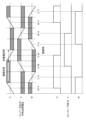
処理部51は、ロータ72を回転させる際、ロータ72の停止位置が、依然、基準位置、本例では、U-V相の位置であるかを判定するために、基準励磁相、本例ではU-V相の位置判定励磁を行う。U-V相を位置判定励磁する場合、処理部51は、励磁の前半期間(A期間)においては、PWMポート58のU-H端子から図7(A)の様にデューティが変化するPWM信号を出力する。具体的には、A期間においては、U-H端子から出力するPWM信号のデューティを正弦波状に変化させる。なお、この正弦波の半周期はA期間の長さに対応し、振幅の最大値は、例えば、80%とする。なお、A期間において、V-L端子はハイレベル(デューティが100%)とし、V相のコイルの一端を所定電位(GND)に接続する。なお、その他の端子はロー(デューティが0%)とする。また、励磁の後半期間(B期間)においては、PWMポート58のV-H端子から図7(B)の様にデューティが変化するPWM信号を出力する。具体的には、B期間においては、V-H端子から出力するPWM信号のデューティを正弦波状に変化させる。この正弦波の半周期もB期間の長さとし、振幅の最大値は、例えば、50%とする。なお、B期間において、U-L端子はハイレベル(デューティが100%)とし、U相のコイルの一端を所定電位(GND)に接続する。なお、その他の端子はロー(デューティが0%)とする。このとき、U-V相に流れる励磁電流は、図7(C)のように正弦波状となる。また、図7におけるA期間およびB期間の時間幅は、ロータ72が回転しない時間幅を上限とし、本例では、5msとしている。
When rotating the
処理部51は、A期間及びB期間において、所定の期間毎、例えば25μs毎にU-V相に流れる励磁電流を測定し、測定した励磁電流の積算処理を行う。この励磁電流を積算処理した測定値を、以下では励磁電流積算値と表記する。本実施形態では、U-V相を位置判定励磁した際の励磁電流積算値が、予め決められた第1閾値よりも大きい場合、ロータ72がU-V相の位置に停止していると判定する。一方、U-V相を位置判定励磁したときの励磁電流積算値が、第1閾値以下である場合、処理部51は、ロータ72の停止位置はU-V相の位置ではないと判定する。なお、本実施形態では、励磁電流積算値を、コイル73~75のインダクタンスの大きさに応じて変化する物理量として測定・検知していた。ここで、励磁電流積算値は、インダクタンスが小さくなる程、大きくなる値である。このため、本実施形態では、U-V相を位置判定励磁した際の励磁電流積算値が、予め決められた第1閾値よりも大きい場合、ロータ72がU-V相の位置に停止していると判定している。しかしながら、合成インダクタインスが小さくなる程、小さくなる測定値を使用する場合、U-V相を位置判定励磁した際の測定値が、予め決められた第1閾値よりも小さい場合、ロータ72がU-V相の位置に停止していると判定することになる。
The
本実施形態において、ロータ72の停止位置がU-V相の位置ではないと判定すると、処理部51は、所定の順序に従って他の励磁相を励磁して励磁電流積算値を測定し、第1閾値と比較する。この所定の順序は、例えば、図8に示す順序とすることができる。図8の順序に従う場合、処理部51は、ロータ72の停止位置がU-V相の位置ではないと判定すると、まず、U-W相を位置判定励磁し、励磁電流積算値と第1閾値を比較する。U-W相を位置判定励磁したときの励磁電流積算値が、第1閾値よりも大きい場合、処理部51は、ロータ72がU-W相の位置に停止していると判定する。処理部51は、ロータ72がU-W相の位置に停止していると判定すると、この所定の順序に従う位置判定励磁を終了する。一方、図8に示す様に、U-W相を位置判定励磁したときの励磁電流積算値が、第1閾値以下である場合、処理部51は、ロータ72の停止位置はU-W相の位置ではないと判定する。この場合、処理部51は、図8に示す順序に従ってW-V相を位置判定励磁し、励磁電流積算値と第1閾値とを比較する。W-V相を位置判定励磁したときの励磁電流積算値が、図8に示す様に、第1閾値よりも大きい場合、処理部51は、ロータ72の停止位置はW-V相の位置であると判定し、以後の励磁相に対する位置判定励磁を停止する。なお、W-V相を位置判定励磁したときの励磁電流積算値が、第1閾値以下である場合、励磁電流積算値が第1閾値より大きくなるまで、順に、図8に示す励磁順に従い位置判定励磁を行う。
In the present embodiment, when it is determined that the stop position of the
以上の構成により、モータ151の駆動開始前毎に、常に、総ての励磁相の位置判定励磁を行う必要がなくなり、より少ない励磁相に対する位置判定励磁のみでロータ72の回転位置を判定することが可能になる。よって、ロータ72の停止位置の判定に要する時間を平均的に短縮することができる。
With the above configuration, it is not necessary to perform position determination excitation for all the excitation phases every time the
なお、図8に示す様に、位置判定励磁を行う順序は、基準励磁相を最初に励磁する励磁相とし、その後は、6つの励磁相の内、基準励磁相との電気角の差が近い順に行う構成とすることができる。具体的には、U-W相及びW-V相は、それぞれ、U-V相との電気角の差が最も小さい励磁相である。また、V-W相及びW-U相は、それぞれ、U-V相との電気角の差が2番目に小さい励磁相である。さらに、V-U相は、U-V相との電気角の差が最も大きい励磁相である。言い換えると、6つの励磁相の位置の内、基準位置との角度が小さい位置にロータ72を停止させる励磁相ほど、位置判定励磁を行う順序を早くする。本実施形態では、ロータ72を基準位置に停止させるため、ロータ72が振動等によりその後に動いたとしても、基準位置との距離が近い位置で停止している可能性が高い。したがって、上記の順序で位置判定励磁を行うことで、励磁電流積算値が第1閾値を超える励磁相を、早い段階で見つけることができ、ロータ72の停止位置の判定に要する時間を平均的に短縮することができる。
In addition, as shown in FIG. 8, the order in which position determination excitation is performed is such that the reference excitation phase is the excitation phase to be excited first, and then, among the six excitation phases, the phases having the closest electrical angle difference to the reference excitation phase are selected. It can be configured to be performed in order. Specifically, the UW phase and the WV phase are excitation phases having the smallest difference in electrical angle from the UV phase. Also, the VW phase and the WU phase are excitation phases having the second smallest difference in electrical angle from the UV phase. Furthermore, the VU phase is the excitation phase having the largest electrical angle difference from the UV phase. In other words, among the positions of the six excitation phases, the excitation phase that stops the
なお、位置判定励磁を行う順序は、図8に示す順序に限定されず、例えば、ロータ72を回転させる際に励磁する順序と同じ順序といった、他の順序であっても良い。 Note that the order of performing position determination excitation is not limited to the order shown in FIG.
また、本実施形態では、インダクタンスの変化に応じて変化する物理量として、励磁相を所定時間だけ励磁した際の励磁電流の積分値である励磁電流積算値を使用していた。しかしながら、インダクタンスの変化に応じて変化する物理量の測定値は、励磁電流積算値に限定されない。例えば、図7(C)に示す励磁電流のピーク値(最大値)や、励磁開始から所定期間後における励磁電流値や、励磁開始から励磁電流の値が所定値に達するまでの時間等を測定値として使用することができる。なお、上述した様に、測定値がインダクタンスの増加に応じて増加する値であるか、減少する値であるかにより、閾値との大小関係と判定結果は異なる。また、本実施形態では、図7(A)及び(B)に示す様に、PWM信号のデューティを正弦波状に変化させたが、三角波状や台形波状に変化させることもできる。 Further, in this embodiment, the excitation current integrated value, which is the integrated value of the excitation current when the excitation phase is excited for a predetermined time, is used as the physical quantity that changes according to the change in the inductance. However, the measured value of the physical quantity that changes with changes in inductance is not limited to the exciting current integrated value. For example, the peak value (maximum value) of the excitation current shown in FIG. 7(C), the excitation current value after a predetermined period from the start of excitation, the time from the start of excitation until the value of the excitation current reaches a predetermined value, etc. are measured. can be used as a value. As described above, the magnitude relationship with the threshold value and the determination result differ depending on whether the measured value is a value that increases or decreases as the inductance increases. Further, in this embodiment, as shown in FIGS. 7A and 7B, the duty of the PWM signal is changed in a sinusoidal waveform, but it can also be changed in a triangular or trapezoidal waveform.
また、本実施形態は、3相(U、V、W)モータの励磁相として、6つの励磁相を使用するものであってが、本発明は、任意の相数のモータに適用でき、かつ、励磁相に含まれるコイルの数も、2つに限定されない。 Further, although this embodiment uses six excitation phases as the excitation phases of a three-phase (U, V, W) motor, the present invention can be applied to motors with any number of phases, and , the number of coils included in the excitation phase is not limited to two.
また、本実施形態では、ロータ72を停止させる際、処理部51は、ロータ72が基準位置で停止する様に制御していた。しかしながら、ロータ72を停止させた後、ロータ72を基準位置に移動させる様に、処理部51が強制転流制御を行う構成であっても良い。つまり、ロータ72の回転駆動を開始する前までに、ロータ72を基準位置に移動させれば良い。
Further, in this embodiment, when stopping the
さらに、ロータ72を停止させる際、ロータ72が基準位置で停止する様に制御しない構成とすることもできる。この場合においても、処理部51は、基準励磁相を起点として、位置判定励磁で測定された励磁電流積算値が第1閾値を超えるまで、例えば、図8に示す順序で、各励磁相の位置判定励磁を行う。そして、処理部51は、その励磁電流積算値が第1閾値を超えた励磁相に対応する回転位置が、ロータ72の停止位置と判定する。この様な構成においても、常に、総ての励磁相の位置判定励磁を行う必要がなくなり、ロータ72の停止位置の判定に要する時間を平均的に短縮することができる。
Furthermore, when stopping the
<第二実施形態>
続いて、第二実施形態について第一実施形態との相違点を中心に説明する。第一実施形態において、処理部51は、1つの励磁相のみの位置判定励磁を行って、ロータ72が当該励磁相の位置であるか否かを判定していた。本実施形態では、まず、基準励磁相を判定対象励磁相とし、判定対象励磁相と、当該判定対象励磁相と電気角的に隣接する2つの隣接励磁相の一方の隣接励磁相との2つの励磁相に対して位置判定励磁を順に行う。具体的には、本例では、U-V相が基準励磁相であるため、U-V相を判定対象励磁相とし、処理部51は、U-V相と、U-W相又はW-V相の位置判定励磁を行う。以下の説明において、処理部51は、U-V相とU-W相の位置判定励磁を行うものとする。このとき、処理部51は、U-V相を位置判定励磁したときの第1励磁電流積算値と、U-W相を位置判定励磁したときの第2励磁電流積算値を測定する。そして、処理部51は、判定対象励磁相に対応する第1励磁電流積算値が、予め決められた第1閾値よりも大きく、且つ、第2励磁電流積算値が第1閾値以下である場合、ロータ72が判定対象励磁相であるU-V相の位置に停止していると判定する。なお、測定値がインダクタンスの増加に応じて増加するものであると、処理部51は、U-V相を励磁した際の測定値が第1閾値よりも小さく、U-W相を励磁した際の測定値が第1閾値以上である場合、ロータ72がU-V相の位置に停止していると判定する。上記条件を満たさない場合、処理部51は、ロータ72が判定対象励磁相であるU-V相の位置に停止していないと判定する。この場合、処理部51は、例えば、図8に示す励磁の順序に従い判定対象励磁相を選択して、ロータ72が判定対象励磁相の位置に停止しているか否かを判定することを繰り返す。
<Second embodiment>
Next, the second embodiment will be described, focusing on differences from the first embodiment. In the first embodiment, the
なお、隣接する2つの励磁相を励磁した際の2つの励磁電流積算値の差分と、第2閾値とを比較する構成とすることもできる。例えば、処理部51は、まず、判定対象励磁相であるU-V相を位置判定励磁したときの第1励磁電流積算値と、U-W相を位置判定励磁したときの第2励磁電流積算値との第1差分を求める。そして、第1励磁電流積算値が第2励磁電流積算値より大きく、かつ、第1差分が第2閾値より大きいと、処理部は、ロータ72が、判定対象励磁相であるU-V相の位置に停止していると判定する。上記条件を満たさない場合、処理部51は、ロータ72が判定対象励磁相であるU-V相の位置に停止していないと判定する。この場合、処理部51は、例えば、図8に示す励磁の順序に従い判定対象励磁相を選択して、ロータ72が判定対象励磁相の位置に停止しているか否かを判定することを繰り返す。
It is also possible to adopt a configuration in which the difference between the two excitation current integrated values when two adjacent excitation phases are excited is compared with the second threshold. For example, the
以上の構成により、モータ151の駆動開始前毎に、常に、総ての励磁相の位置判定励磁を行う必要がなくなり、より少ない励磁相に対する位置判定励磁のみでロータ72の位置を判定することが可能になる。よって、ロータ72の停止位置の判定に要する時間を平均的に短縮することができる。
With the above configuration, it is not necessary to always perform position determination excitation for all the excitation phases every time the
<第三実施形態>
続いて、第三実施形態について第一実施形態及び第二実施形態との相違点を中心に説明する。第一実施形態においては、ロータ72を基準位置で停止させる形態と、ロータ72を基準位置で停止させない形態とについて説明した。本実施形態において、処理部51は、ロータ72を基準位置で停止させる。つまり、処理部51は、ロータ72を停止させる際、ロータ72が基準位置で停止する様に制御するか、ロータ72を停止させた後、ロータ72を基準位置に移動させる制御を行う。
<Third embodiment>
Next, the third embodiment will be described, focusing on differences from the first and second embodiments. In the first embodiment, the form in which the
ロータ72の停止時、その位置は、画像形成装置を移動させるといった、大きな振動が画像形成装置に加わると回転し得るが、通常の利用時には、ロータ72に外部から力が加わることは稀である。したがって、本実施形態では、ロータ72は、基本的には、基準位置の近傍で停止していることを前提とする。しかしながら、ロータ72を回転させる際、ロータ72の回転位置が、U-V相の位置とU-W相の位置との間であることや、U-V相の位置とW-V相の位置との間であることが生じ得る。
When the
図9(A)は、ロータ72が、U-V相とU-W相の中間位置へ移動した状態を示している。図9(B)は、図9(A)の状態において、U-V相を位置判定励磁した状態を示し、図9(C)は、図9(A)の状態において、U-W相を位置判定励磁励磁した状態を示している。図9(B)及び(C)において、U相のコイル73(N極)には、ロータ72のS極のみが対向している。しかしながら、図9(B)に示す様に、U-V相の位置判定励磁において、V相のコイル74には、ロータ72のS極及びN極が対向し、図9(C)に示す様に、U-W相の位置判定励磁において、W相のコイル74には、ロータ72のS極及びN極が対向している。したがって、図9(A)の状態の場合、ロータ72がU-V相の位置で停止している場合と比較して、U-V相を位置判定励磁した際の励磁電流積算値は小さくなる。なお、ロータ72が、図9(A)の位置で停止している場合、U-V相の位置判定励磁で得られる励磁電流積算値と、U-W相の位置判定励磁で得られる励磁電流積算値は同程度で、他の励磁相を励磁した際の励磁電流積算値より大きくなる。
FIG. 9A shows a state in which the
このため、本実施形態において、処理部51は、まず、基準励磁相を判定対象励磁相とし、判定対象励磁相と、判定対象励磁相の2つの隣接励磁相の位置判定励磁を行う。具体的には、本例では、U-V相が基準励磁相であるため、処理部51は、U-V相と、U-W相及びW-V相の位置判定励磁を行う。そして、処理部51は、判定対象励磁相であるU-V相の第1励磁電流積算値と、U-W相の第2励磁電流積算値と、W-V相の第3励磁電流積算値とを測定する。続いて、処理部51は、第1励磁電流積算値と第2励磁電流積算値との第1差分と、第1励磁電流積算値と第3励磁電流積算値との第2差分と、を求める。処理部51は、第1励磁電流積算値が、第2励磁電流積算値及び第3励磁電流積算値より大きく、かつ、第1差分及び第2差分の両方が第3閾値よりも大きいと、ロータ72が、判定対象励磁相であるU-V相の位置に停止していると判定する。
Therefore, in the present embodiment, the
また、処理部51は、第1励磁電流積算値が第3励磁電流積算値より大きく、第2差分が第3閾値よりも大きいが、第1差分が第3閾値以下であると、ロータ72がU-V相とU-W相の間の位置に停止していると判定する。一方、処理部51は、第1励磁電流積算値が第2励磁電流積算値より大きく、第1差分が第3閾値よりも大きいが、第2差分が第3閾値未満であると、ロータ72がU-V相とW-V相の間の位置に停止していると判定する。なお、上記のいずれにも該当しないと、処理部51は、図8に示す励磁の順序に従い判定対象励磁相を選択して、ロータ72の回転位置の判定ができるまで処理を繰り返す。
Further, the
以上の構成により、モータ151の駆動開始前毎に、常に、総ての励磁相の位置判定励磁を行う必要がなくなり、より少ない励磁相に対する位置判定励磁のみでロータ72の位置を判定することが可能になる。よって、ロータ72の停止位置の判定に要する時間を平均的に短縮することができる。
With the above configuration, it is not necessary to always perform position determination excitation for all the excitation phases every time the
「その他の実施形態」
なお、上記各実施形態では、画像形成装置10の一構成要素であるためモータ制御部41と表記したが、モータ制御部41を1つの装置としてモータ制御装置とすることもできる。また、制御部40及びモータ制御部41を含む装置をモータ制御装置とすることもできる。また、上記実施形態において、モータ151は、感光体11といった、画像形成装置10の画像形成に関する回転部材を回転させるものであったが、記録材Pを搬送するためのモータに対しても本発明を適用できる。また、モータ151の構成は、図4に示す構成に限定されず、他の極数や相数のモータであっても良い。
"Other Embodiments"
In each of the above-described embodiments, the
本発明は、上述の実施形態の1以上の機能を実現するプログラムを、ネットワーク又は記憶媒体を介してシステム又は装置に供給し、そのシステム又は装置のコンピュータにおける1つ以上のプロセッサーがプログラムを読出し実行する処理でも実現可能である。また、1以上の機能を実現する回路(例えば、ASIC)によっても実現可能である。 The present invention supplies a program that implements one or more functions of the above-described embodiments to a system or device via a network or a storage medium, and one or more processors in the computer of the system or device reads and executes the program. It can also be realized by processing to It can also be implemented by a circuit (for example, ASIC) that implements one or more functions.
発明は上記実施形態に制限されるものではなく、発明の精神及び範囲から離脱することなく、様々な変更及び変形が可能である。従って、発明の範囲を公にするために請求項を添付する。 The invention is not limited to the embodiments described above, and various modifications and variations are possible without departing from the spirit and scope of the invention. Accordingly, the claims are appended to make public the scope of the invention.
60:3相インバータ、53:ADコンバータ、51:処理部 60: 3-phase inverter, 53: AD converter, 51: processing unit
Claims (9)
前記複数の励磁相を構成する複数のコイルの少なくとも1つのコイルのインダクタンスに応じて変化する物理量を、前記複数の励磁相それぞれを励磁した際に測定する測定手段と、
前記励磁手段を制御する制御手段と、
を備え、
前記複数の励磁相は、それぞれ、前記複数のコイルの内の2つのコイルの順列で識別され、
前記測定手段は、第1コイル、第2コイルの順で識別される励磁相を励磁して当該励磁相の前記物理量を測定するために、第1期間においては前記第1コイルに電圧を印可し、前記第1期間に続く第2期間においては前記第2コイルに電圧を印可し、
前記制御手段は、前記モータのロータの停止位置を判定する期間において、前記複数の励磁相を順番に励磁し、前記複数の励磁相それぞれを励磁した際に前記測定手段によって測定された測定値と第1閾値とを順に比較することで前記モータの前記ロータの前記停止位置を判定し、
前記モータの前記ロータの前記停止位置を判定すると、前記制御手段は、前記複数の励磁相の残りの励磁相を励磁しないことを特徴とするモータ制御装置。 excitation means for exciting a plurality of excitation phases of the motor;
measuring means for measuring a physical quantity that changes according to the inductance of at least one of the plurality of coils constituting the plurality of excitation phases when each of the plurality of excitation phases is excited;
a control means for controlling the excitation means;
with
each of the plurality of excitation phases is identified by a permutation of two of the plurality of coils;
The measuring means applies a voltage to the first coil during the first period in order to excite the excitation phases identified in the order of the first coil and the second coil and measure the physical quantity of the excitation phases. , applying a voltage to the second coil in a second period following the first period;
The control means sequentially excites the plurality of excitation phases during a period for determining the stop position of the rotor of the motor, and measures the values measured by the measurement means when each of the plurality of excitation phases is excited. determining the stop position of the rotor of the motor by sequentially comparing a first threshold;
A motor control device, wherein when the stop position of the rotor of the motor is determined, the control means does not excite the remaining excitation phases of the plurality of excitation phases.
前記測定値が前記インダクタンスの減少に応じて増加するものである場合、前記第1励磁相は、前記励磁手段により励磁した際の前記測定値が前記第1閾値より大きい励磁相であり、
前記測定値が前記インダクタンスの減少に応じて減少するものである場合、前記第1励磁相は、前記励磁手段により励磁した際の前記測定値が第1閾値より小さい励磁相であることを特徴とする請求項1から5のいずれか1項に記載のモータ制御装置。 The control means determines a first excitation phase from the plurality of excitation phases, and determines the stop position of the rotor of the motor as a rotational position at which the rotor stops when the first excitation phase is excited. judge,
when the measured value increases as the inductance decreases, the first excitation phase is an excitation phase in which the measured value when excited by the excitation means is greater than the first threshold;
When the measured value decreases as the inductance decreases, the first excitation phase is an excitation phase in which the measured value when excited by the excitation means is smaller than a first threshold. The motor control device according to any one of claims 1 to 5.
前記搬送路を搬送される前記シートに画像を形成する画像形成手段と、
前記回転部材又は前記画像形成手段を駆動するモータと、
前記モータを制御する請求項1から8のいずれか1項に記載のモータ制御装置と、
を備えていることを特徴とする画像形成装置。 a rotating member for transporting the sheet along the transport path;
image forming means for forming an image on the sheet conveyed on the conveying path;
a motor that drives the rotating member or the image forming means;
a motor control device according to any one of claims 1 to 8 , which controls the motor;
An image forming apparatus comprising:
Priority Applications (2)
| Application Number | Priority Date | Filing Date | Title |
|---|---|---|---|
| JP2019008599A JP7296733B2 (en) | 2019-01-22 | 2019-01-22 | Motor control device and image forming device |
| US16/748,118 US11329580B2 (en) | 2019-01-22 | 2020-01-21 | Motor control apparatus and image forming apparatus |
Applications Claiming Priority (1)
| Application Number | Priority Date | Filing Date | Title |
|---|---|---|---|
| JP2019008599A JP7296733B2 (en) | 2019-01-22 | 2019-01-22 | Motor control device and image forming device |
Publications (3)
| Publication Number | Publication Date |
|---|---|
| JP2020120468A JP2020120468A (en) | 2020-08-06 |
| JP2020120468A5 JP2020120468A5 (en) | 2022-01-21 |
| JP7296733B2 true JP7296733B2 (en) | 2023-06-23 |
Family
ID=71610102
Family Applications (1)
| Application Number | Title | Priority Date | Filing Date |
|---|---|---|---|
| JP2019008599A Active JP7296733B2 (en) | 2019-01-22 | 2019-01-22 | Motor control device and image forming device |
Country Status (2)
| Country | Link |
|---|---|
| US (1) | US11329580B2 (en) |
| JP (1) | JP7296733B2 (en) |
Families Citing this family (3)
| Publication number | Priority date | Publication date | Assignee | Title |
|---|---|---|---|---|
| JP7324008B2 (en) | 2019-01-22 | 2023-08-09 | キヤノン株式会社 | Motor control device and image forming device |
| JP7450458B2 (en) | 2020-05-29 | 2024-03-15 | キヤノン株式会社 | Motor control device and image forming device |
| JP2022139898A (en) * | 2021-03-12 | 2022-09-26 | キヤノン株式会社 | Image forming apparatus |
Citations (6)
| Publication number | Priority date | Publication date | Assignee | Title |
|---|---|---|---|---|
| JP2006271179A (en) | 2005-02-23 | 2006-10-05 | Mitsubishi Heavy Ind Ltd | Motor control unit and motor control method |
| JP2010154727A (en) | 2008-12-24 | 2010-07-08 | E-Bike Corp | Drive method of starting brushless dc motor having no position detector and electric bicycle using the same |
| JP2012253893A (en) | 2011-06-02 | 2012-12-20 | Mitsuba Corp | Drive unit and stop position detection method |
| JP2015104263A (en) | 2013-11-26 | 2015-06-04 | キヤノン株式会社 | Motor control device and image forming apparatus |
| JP2017118680A (en) | 2015-12-24 | 2017-06-29 | コニカミノルタ株式会社 | Three-phase dc brushless motor controller and image forming apparatus |
| JP2018078695A (en) | 2016-11-08 | 2018-05-17 | 北斗制御株式会社 | Field position detection method for electric motor |
Family Cites Families (7)
| Publication number | Priority date | Publication date | Assignee | Title |
|---|---|---|---|---|
| JPH07274585A (en) | 1994-03-30 | 1995-10-20 | Hokuto Seigyo Kk | Method for detecting stop position of, and control equipment for drive of, brushless motor |
| JPH08266088A (en) * | 1995-03-27 | 1996-10-11 | Nippondenso Co Ltd | Controller for motor |
| JP2003079184A (en) | 2001-08-30 | 2003-03-14 | Canon Inc | Sensorless motor control equipment, imaging equipment, control method of the imaging equipment, and control program of the imaging equipment |
| KR100713776B1 (en) * | 2005-10-04 | 2007-05-02 | 에스알텍 주식회사 | Detection method of excitation position of SRM by comparison of detected current and apparatus thereof |
| JP2008092784A (en) | 2006-07-28 | 2008-04-17 | Mitsuba Corp | Drive unit for brushless motor, and method for starting the brushless motor and method for detecting stopping position of rotor of the brushless motor |
| JP7016762B2 (en) * | 2018-04-13 | 2022-02-07 | ルネサスエレクトロニクス株式会社 | Semiconductor devices, motor drive systems, and motor control programs |
| JP7450458B2 (en) * | 2020-05-29 | 2024-03-15 | キヤノン株式会社 | Motor control device and image forming device |
-
2019
- 2019-01-22 JP JP2019008599A patent/JP7296733B2/en active Active
-
2020
- 2020-01-21 US US16/748,118 patent/US11329580B2/en active Active
Patent Citations (6)
| Publication number | Priority date | Publication date | Assignee | Title |
|---|---|---|---|---|
| JP2006271179A (en) | 2005-02-23 | 2006-10-05 | Mitsubishi Heavy Ind Ltd | Motor control unit and motor control method |
| JP2010154727A (en) | 2008-12-24 | 2010-07-08 | E-Bike Corp | Drive method of starting brushless dc motor having no position detector and electric bicycle using the same |
| JP2012253893A (en) | 2011-06-02 | 2012-12-20 | Mitsuba Corp | Drive unit and stop position detection method |
| JP2015104263A (en) | 2013-11-26 | 2015-06-04 | キヤノン株式会社 | Motor control device and image forming apparatus |
| JP2017118680A (en) | 2015-12-24 | 2017-06-29 | コニカミノルタ株式会社 | Three-phase dc brushless motor controller and image forming apparatus |
| JP2018078695A (en) | 2016-11-08 | 2018-05-17 | 北斗制御株式会社 | Field position detection method for electric motor |
Also Published As
| Publication number | Publication date |
|---|---|
| JP2020120468A (en) | 2020-08-06 |
| US11329580B2 (en) | 2022-05-10 |
| US20200235684A1 (en) | 2020-07-23 |
Similar Documents
| Publication | Publication Date | Title |
|---|---|---|
| US10141878B2 (en) | Controller for permanent magnet synchronous motor, and control method for estimating initial position of rotor | |
| US9431940B2 (en) | Motor control apparatus for sensorless motor, and image forming apparatus | |
| US11381191B2 (en) | Motor control apparatus for determining motor type and image forming apparatus | |
| JP7296733B2 (en) | Motor control device and image forming device | |
| JP6592777B2 (en) | Sensorless brushless motor control method and image forming apparatus | |
| CN111342732B (en) | Motor control device and image forming apparatus | |
| JP7152875B2 (en) | Motor control device and image forming device | |
| JP2018007505A (en) | Motor controller and image forming apparatus | |
| JP2020115731A (en) | Motor controller and image forming apparatus | |
| JP7450458B2 (en) | Motor control device and image forming device | |
| JP2018098856A (en) | Control device of permanent magnet synchronous motor, image formation apparatus and control method | |
| JP2006058364A (en) | Image forming apparatus | |
| JP7324008B2 (en) | Motor control device and image forming device | |
| JP7389616B2 (en) | Motor control device and image forming device | |
| JP7236311B2 (en) | Motor control device and image forming device | |
| CN110572104A (en) | Control device for permanent magnet synchronous motor and image forming apparatus | |
| JP2022011042A (en) | Motor controller and image forming apparatus | |
| JP7292049B2 (en) | Motor control device and image forming device | |
| JP7381316B2 (en) | Motor control device and image forming device | |
| JP2022184571A (en) | Motor control device and image formation device | |
| JP2021056487A (en) | Image forming apparatus, motor control unit for controlling motor, and method for controlling motor | |
| JP2017184489A (en) | Motor drive unit and image formation device |
Legal Events
| Date | Code | Title | Description |
|---|---|---|---|
| RD01 | Notification of change of attorney |
Free format text: JAPANESE INTERMEDIATE CODE: A7421 Effective date: 20210103 |
|
| A521 | Request for written amendment filed |
Free format text: JAPANESE INTERMEDIATE CODE: A523 Effective date: 20210113 |
|
| A521 | Request for written amendment filed |
Free format text: JAPANESE INTERMEDIATE CODE: A523 Effective date: 20220113 |
|
| A621 | Written request for application examination |
Free format text: JAPANESE INTERMEDIATE CODE: A621 Effective date: 20220113 |
|
| A977 | Report on retrieval |
Free format text: JAPANESE INTERMEDIATE CODE: A971007 Effective date: 20221116 |
|
| A131 | Notification of reasons for refusal |
Free format text: JAPANESE INTERMEDIATE CODE: A131 Effective date: 20221202 |
|
| A521 | Request for written amendment filed |
Free format text: JAPANESE INTERMEDIATE CODE: A523 Effective date: 20230125 |
|
| TRDD | Decision of grant or rejection written | ||
| A01 | Written decision to grant a patent or to grant a registration (utility model) |
Free format text: JAPANESE INTERMEDIATE CODE: A01 Effective date: 20230515 |
|
| A61 | First payment of annual fees (during grant procedure) |
Free format text: JAPANESE INTERMEDIATE CODE: A61 Effective date: 20230613 |
|
| R151 | Written notification of patent or utility model registration |
Ref document number: 7296733 Country of ref document: JP Free format text: JAPANESE INTERMEDIATE CODE: R151 |