JP7293232B2 - Accessories and camera systems equipped with them - Google Patents
Accessories and camera systems equipped with them Download PDFInfo
- Publication number
- JP7293232B2 JP7293232B2 JP2020535466A JP2020535466A JP7293232B2 JP 7293232 B2 JP7293232 B2 JP 7293232B2 JP 2020535466 A JP2020535466 A JP 2020535466A JP 2020535466 A JP2020535466 A JP 2020535466A JP 7293232 B2 JP7293232 B2 JP 7293232B2
- Authority
- JP
- Japan
- Prior art keywords
- optical axis
- operating member
- accessory according
- operation ring
- accessory
- Prior art date
- Legal status (The legal status is an assumption and is not a legal conclusion. Google has not performed a legal analysis and makes no representation as to the accuracy of the status listed.)
- Active
Links
Images


Classifications
-
- G—PHYSICS
- G02—OPTICS
- G02B—OPTICAL ELEMENTS, SYSTEMS OR APPARATUS
- G02B7/00—Mountings, adjusting means, or light-tight connections, for optical elements
- G02B7/02—Mountings, adjusting means, or light-tight connections, for optical elements for lenses
- G02B7/04—Mountings, adjusting means, or light-tight connections, for optical elements for lenses with mechanism for focusing or varying magnification
- G02B7/09—Mountings, adjusting means, or light-tight connections, for optical elements for lenses with mechanism for focusing or varying magnification adapted for automatic focusing or varying magnification
-
- G—PHYSICS
- G02—OPTICS
- G02B—OPTICAL ELEMENTS, SYSTEMS OR APPARATUS
- G02B7/00—Mountings, adjusting means, or light-tight connections, for optical elements
- G02B7/02—Mountings, adjusting means, or light-tight connections, for optical elements for lenses
- G02B7/14—Mountings, adjusting means, or light-tight connections, for optical elements for lenses adapted to interchange lenses
-
- G—PHYSICS
- G02—OPTICS
- G02B—OPTICAL ELEMENTS, SYSTEMS OR APPARATUS
- G02B7/00—Mountings, adjusting means, or light-tight connections, for optical elements
- G02B7/28—Systems for automatic generation of focusing signals
-
- G—PHYSICS
- G03—PHOTOGRAPHY; CINEMATOGRAPHY; ANALOGOUS TECHNIQUES USING WAVES OTHER THAN OPTICAL WAVES; ELECTROGRAPHY; HOLOGRAPHY
- G03B—APPARATUS OR ARRANGEMENTS FOR TAKING PHOTOGRAPHS OR FOR PROJECTING OR VIEWING THEM; APPARATUS OR ARRANGEMENTS EMPLOYING ANALOGOUS TECHNIQUES USING WAVES OTHER THAN OPTICAL WAVES; ACCESSORIES THEREFOR
- G03B13/00—Viewfinders; Focusing aids for cameras; Means for focusing for cameras; Autofocus systems for cameras
- G03B13/32—Means for focusing
-
- G—PHYSICS
- G03—PHOTOGRAPHY; CINEMATOGRAPHY; ANALOGOUS TECHNIQUES USING WAVES OTHER THAN OPTICAL WAVES; ELECTROGRAPHY; HOLOGRAPHY
- G03B—APPARATUS OR ARRANGEMENTS FOR TAKING PHOTOGRAPHS OR FOR PROJECTING OR VIEWING THEM; APPARATUS OR ARRANGEMENTS EMPLOYING ANALOGOUS TECHNIQUES USING WAVES OTHER THAN OPTICAL WAVES; ACCESSORIES THEREFOR
- G03B17/00—Details of cameras or camera bodies; Accessories therefor
- G03B17/02—Bodies
- G03B17/12—Bodies with means for supporting objectives, supplementary lenses, filters, masks, or turrets
- G03B17/14—Bodies with means for supporting objectives, supplementary lenses, filters, masks, or turrets interchangeably
-
- G—PHYSICS
- G03—PHOTOGRAPHY; CINEMATOGRAPHY; ANALOGOUS TECHNIQUES USING WAVES OTHER THAN OPTICAL WAVES; ELECTROGRAPHY; HOLOGRAPHY
- G03B—APPARATUS OR ARRANGEMENTS FOR TAKING PHOTOGRAPHS OR FOR PROJECTING OR VIEWING THEM; APPARATUS OR ARRANGEMENTS EMPLOYING ANALOGOUS TECHNIQUES USING WAVES OTHER THAN OPTICAL WAVES; ACCESSORIES THEREFOR
- G03B3/00—Focusing arrangements of general interest for cameras, projectors or printers
- G03B3/02—Focusing arrangements of general interest for cameras, projectors or printers moving lens along baseboard
-
- G—PHYSICS
- G03—PHOTOGRAPHY; CINEMATOGRAPHY; ANALOGOUS TECHNIQUES USING WAVES OTHER THAN OPTICAL WAVES; ELECTROGRAPHY; HOLOGRAPHY
- G03B—APPARATUS OR ARRANGEMENTS FOR TAKING PHOTOGRAPHS OR FOR PROJECTING OR VIEWING THEM; APPARATUS OR ARRANGEMENTS EMPLOYING ANALOGOUS TECHNIQUES USING WAVES OTHER THAN OPTICAL WAVES; ACCESSORIES THEREFOR
- G03B3/00—Focusing arrangements of general interest for cameras, projectors or printers
- G03B3/10—Power-operated focusing
-
- G—PHYSICS
- G03—PHOTOGRAPHY; CINEMATOGRAPHY; ANALOGOUS TECHNIQUES USING WAVES OTHER THAN OPTICAL WAVES; ELECTROGRAPHY; HOLOGRAPHY
- G03B—APPARATUS OR ARRANGEMENTS FOR TAKING PHOTOGRAPHS OR FOR PROJECTING OR VIEWING THEM; APPARATUS OR ARRANGEMENTS EMPLOYING ANALOGOUS TECHNIQUES USING WAVES OTHER THAN OPTICAL WAVES; ACCESSORIES THEREFOR
- G03B5/00—Adjustment of optical system relative to image or object surface other than for focusing
- G03B5/04—Vertical adjustment of lens; Rising fronts
-
- G—PHYSICS
- G03—PHOTOGRAPHY; CINEMATOGRAPHY; ANALOGOUS TECHNIQUES USING WAVES OTHER THAN OPTICAL WAVES; ELECTROGRAPHY; HOLOGRAPHY
- G03B—APPARATUS OR ARRANGEMENTS FOR TAKING PHOTOGRAPHS OR FOR PROJECTING OR VIEWING THEM; APPARATUS OR ARRANGEMENTS EMPLOYING ANALOGOUS TECHNIQUES USING WAVES OTHER THAN OPTICAL WAVES; ACCESSORIES THEREFOR
- G03B2217/00—Details of cameras or camera bodies; Accessories therefor
- G03B2217/002—Details of arrangement of components in or on camera body
Description
本発明は、アクセサリ及びこれを備えるカメラシステムに関する。 The present invention relates to an accessory and a camera system including the same.
ズームリング及びフォーカスリングに加えて、機能を変更することが可能な第3の操作リングを備えたレンズ装置として特許文献1に記載のレンズ装置が知られている。特許文献1のレンズ装置では、カメラ本体側から順にズーム操作リング、フォーカス操作リング、カスタム操作リングが設けられている。このカスタム操作リングに絞り値変更機能、シャッタ速度変更機能、露出補正機能、連射速度調節機能のいずれかを割り当てることが可能である。 A lens device described in Patent Document 1 is known as a lens device including a third operation ring whose function can be changed in addition to a zoom ring and a focus ring. In the lens device of Patent Document 1, a zoom operation ring, a focus operation ring, and a custom operation ring are provided in order from the camera body side. It is possible to assign any one of aperture value changing function, shutter speed changing function, exposure compensation function, and continuous shooting speed adjusting function to this custom operation ring.
特許文献1のレンズ装置では、カスタム操作リングとフォーカス操作リングが互いに近接して配置されているが、互いに近接して配置された2つの操作リングの表面構造が同じ場合には、ユーザーがこれら2つの操作リングを識別するのが困難になってしまう。特許文献1には、カスタム操作リングとフォーカス操作リングの表面構造について明記されていない。 In the lens device of Patent Document 1, the custom operation ring and the focus operation ring are arranged close to each other. It becomes difficult to identify one operating ring. Patent Document 1 does not specify the surface structures of the custom operation ring and the focus operation ring.
そこで本発明は、2つの操作部材を識別しやすいアクセサリ及びこれを備えるカメラシステムを提供することを目的とする。 SUMMARY OF THE INVENTION Accordingly, it is an object of the present invention to provide an accessory and a camera system including the accessory that allow easy identification of two operating members.
上記目的を達成するために、本発明のアクセサリは、
フォーカスのために光軸方向に移動するフォーカスレンズユニットと、
ズームのために前記光軸方向に移動するズームレンズユニットと、
前記フォーカスレンズユニットを前記光軸方向に移動させるために操作される第1の操作部材と、
フォーカスとは異なる複数の種類のパラメータから選択的に割り当てられたパラメータを調整するために操作される第2の操作部材と、
前記ズームレンズユニットを前記光軸方向に移動させるために操作される第3の操作部材とを備えるアクセサリであって、
前記第1の操作部材の前記光軸方向の幅は、前記第2の操作部材の前記光軸方向の幅よりも広く、
前記第1の操作部材および前記第3の操作部材の表面の材料はゴムであり、前記第2の操作部材の表面の材料はプラスチックであり、
前記第1の操作部材、および前記第3の操作部材の表面には平目状の溝構造が設けられており、前記第2の操作部材の表面には網目状の溝構造が設けられており、
前記第3の操作部材の平目状の溝構造のピッチが第1の操作部材の平目状の溝構造のピッチよりも大きいことを特徴とする。
In order to achieve the above object, the accessory of the present invention is
a focus lens unit that moves in the optical axis direction for focusing;
a zoom lens unit that moves in the optical axis direction for zooming;
a first operation member operated to move the focus lens unit in the optical axis direction;
a second operating member operated to adjust a parameter selectively assigned from a plurality of types of parameters different from focus;
and a third operating member operated to move the zoom lens unit in the optical axis direction ,
the width of the first operation member in the optical axis direction is wider than the width of the second operation member in the optical axis direction;
The surface material of the first operating member and the third operating member is rubber, and the surface material of the second operating member is plastic,
A flat groove structure is provided on the surfaces of the first operation member and the third operation member , and a mesh-like groove structure is provided on the surface of the second operation member,
It is characterized in that the pitch of the flat groove structure of the third operating member is larger than the pitch of the flat groove structure of the first operating member.
本発明によれば、2つの操作部材を識別しやすいアクセサリ及びこれを備えるカメラシステムを提供することが可能となる。 ADVANTAGE OF THE INVENTION According to this invention, it becomes possible to provide the accessory which can distinguish two operation members easily, and a camera system provided with the same.
以下、本発明の実施の形態を添付の図面に基づいて説明する。 BEST MODE FOR CARRYING OUT THE INVENTION Embodiments of the present invention will be described below with reference to the accompanying drawings.
(カメラシステムのブロック構成)
まず、図1を用いて本発明の実施例における交換レンズ100及びカメラボディ(カメラ本体)200のブロック構成について説明する。図1は交換レンズ(光学機器、アクセサリ、レンズ装置)100とカメラボディ200を備えるカメラシステム300のブロック図である。(Block configuration of camera system)
First, block configurations of an
(カメラボディのブロック構成)
カメラボディ200は、CCDやCMOSなどを含み、交換レンズ100を介して得られた被写体の光情報を電気信号に変換する(被写体像の光電変換を行う)光電変換素子あるいは撮像素子である撮像手段202を備えている。カメラボディ200はさらに、交換レンズ100側のレンズマウント(第2のマウント部)101と結合するカメラマウント(第1のマウント部)201と、撮像手段202などを保持するカメラ筐体205を備えている。(Block configuration of camera body)
The
カメラボディ200は撮像手段202及びカメラマウント201以外に、交換レンズ100側のレンズ通信手段と通信を行うカメラ通信手段、測光を行う測光手段、測距を行う測距手段、撮影した写真や動画のデータなどを記録する記録装置も備えている。カメラボディ200はさらに、シャッタースピードなどの撮影条件などの設定を行う設定手段、ユーザーが操作可能なレリーズ手段(シャッタボタン)、ユーザーに様々な情報を表示するための表示手段、電源を備えている。そして、カメラボディ200はさらに、撮像手段202などを制御するための制御手段であるカメラCPUを備えている。
In addition to the imaging means 202 and the
(交換レンズのブロック構成)
交換レンズ100はカメラボディ200に対して装着可能、着脱可能である。そして、交換レンズ100は、レンズ鏡筒102と、レンズマウント(カメラアクセサリマウント)101を備える。交換レンズ100とカメラボディ200の電気的通信に関しては、相手側と電気的に接続可能な複数の電気コンタクト部を備えるレンズ通信手段とカメラ通信手段によって行う。電力供給情報や制御情報といった各種の情報はカメラCPUとレンズCPUとの間でやり取り(送受信)が可能となっている。(Block configuration of interchangeable lens)
The
交換レンズ100はレンズマウント101以外に、ズーミングの際に移動するズーミングレンズユニットZLU、フォーカシングの際に移動するフォーカシングレンズユニットFLU、手振れ補正のために移動するシフトレンズユニットSLUを備えている。交換レンズ100はさらに、ズーミングレンズユニットZLU、フォーカシングレンズユニットFLU、シフトレンズユニットSLU以外のレンズユニットLU、絞りユニットDU,NDフィルターNDFを備える。ここでいう各レンズユニットが有するレンズは1枚であっても複数であってもよい。
In addition to the
交換レンズ100はさらに、ズーミングレンズユニットZLUを駆動させるためのズーム駆動手段、フォーカシングレンズユニットFLUを駆動させるためのフォーカス駆動手段、絞りユニットDUを駆動させるための絞り駆動手段を備える。交換レンズ100はさらに、NDフィルターNDFを駆動させるためのND駆動手段、シフトレンズユニットSLUを駆動させるための防振駆動手段を備える。交換レンズ100はさらにレンズ通信手段と、レンズ通信手段及び前述の各駆動手段を制御するための制御手段としてのレンズCPUを備える。
The
なお、図1において交換レンズ100はズーミングレンズユニットZLUを備えるズームレンズであるが、交換レンズ100はズーミングレンズユニットZLUを備えない単焦点レンズであってもよい。さらに、交換レンズ100はシフトレンズユニットSLUを備えない構成であってもよい。交換レンズ100はカメラボディ200に対してアダプタを介することなく直接装着可能であればよい。
Note that although the
(第1実施例)
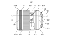
次に図2、図3、図4を用いて交換レンズ100の一つであり、本発明の第1実施例のアクセサリでもある第1の交換レンズ100Aの外観について説明する。図2は第1の交換レンズ100Aの外観を示す図であり、図2Aは光軸Oと直交する第1の方向視における第1の交換レンズ100Aの外観図である。図2Bは光軸Oと直交するとともに第1の方向とは異なる第2の方向視における第1の交換レンズ100Aの外観図である。図3は第1の交換レンズ100Aの外観の模式図である。(First embodiment)
Next, the appearance of the first
図2において、103は、フォーカシングレンズユニットFLUを光軸Oと平行な方向(光軸方向)に移動させるためのフォーカス操作リング(第1の操作部材)である。 In FIG. 2, 103 is a focus operation ring (first operation member) for moving the focusing lens unit FLU in a direction parallel to the optical axis O (optical axis direction).
104は、フォーカシングとは異なる第1の機能及び第2の機能のうちいずれかの機能を実現することが可能なカスタム操作リング(第2の操作部材)である。言い換えれば、カスタム操作リング104にはフォーカシングとは異なる第1の機能と第2の機能のうちいずれかの機能を割り当てることが可能である。
前述の図1に示すカメラボディ200のタッチディスプレイである表示手段は、カスタム操作リング104に割り当てることが可能な複数の機能に対応するボタンを示すことが可能である。そして、表示手段に表示されている複数の機能に対応するボタンのうちユーザーがタッチしたボタンに対応する機能をカスタム操作リング104に割り当てる。つまり、カメラボディ200のタッチディスプレイは表示手段(表示部)であるとともに選択手段(選択部)である。カスタム操作リング104に割り当てる機能の選択は上記の手段に限定されるものではない。交換レンズ100にカスタム操作リング104に割り当てる機能を選択するための選択手段であるスイッチやタッチディスプレイを設けてもよい。あるいは、カメラボディ200にタッチディスプレイとは別に選択手段を設けてもよい。
The display means, which is the touch display of the
カスタム操作リング104に割り当てられる第1の機能及び第2の機能は以下の通りである。すなわち、絞り値、ホワイトバランス、シャッタースピード、ISO感度、露出値などの撮影条件に関するパラメータの調整(変更)機能、マニュアルフォーカスとオートフォーカスの切替機能のいずれか2つである。カスタム操作リング104には第1の機能、第2の機能に加えて、第3、第4の機能も割り当てることができてもよい。
The first and second functions assigned to
(2つの操作部材を識別しやすいアクセサリを実現するための構成)
図2及び図3に示すように、フォーカス操作リング103の表面には平目状の溝構造(第1の構造、縦リブ構造)が設けられており、カスタム操作リング104の表面にはアヤ目状の溝構造(第2の構造、網目状の溝構造)が設けられている。つまり、カスタム操作リング104の表面にはフォーカス操作リング103の表面とは異なる構造が設けられている。このため、2つの操作部材を識別しやすいアクセサリを実現することが可能である。ここでいう平目状の溝構造とは、図3に示すように光軸方向に平行な複数の溝1031を有する構造のことをいう。あるいは、平目状の溝構造とは、平目ローレット加工が施された構造のことをいう。また、アヤ目状の溝構造とは、図3に示すように光軸方向に対して交差する(傾いている)複数の溝1041を有する構造のことをいう。あるいは、アヤ目状の溝構造とは、アヤ目ローレット加工が施された構造のことをいう。(Structure for realizing an accessory that makes it easy to distinguish between two operation members)
As shown in FIGS. 2 and 3, the surface of the
(その他の構成)
カスタム操作リング104の表面に設けられている構造において、計4本の溝1041で囲まれた部分1042は底面がひし形の四角錐形状である。これにより、フォーカス操作リング103の表面の触感とカスタム操作リング104の表面の触感とを互いに異ならせて2つの操作部材をより識別しやすくなる。(Other configurations)
In the structure provided on the surface of the
フォーカス操作リング103の表面の素材は、カスタム操作リング104の表面の素材とは異なっている。フォーカス操作リング103とカスタム操作リング104の間には、前述の表面の構造の違いに加えて触感の違いもあるため、ユーザーが2つの操作部材をより識別しやすくなる。
The material of the surface of the
より具体的には、フォーカス操作リング103はゴムリングを備えているため、フォーカス操作リング103の表面の素材はゴムである。そして、カスタム操作リング104は射出形成されたプラスチック製のリング状部材を備えているため、カスタム操作リング104の表面の素材はフォーカス操作リング103の表面の素材よりも弾性変形しにくい。言い換えれば、フォーカス操作リング103の表面の素材は、カスタム操作リング104の表面の素材よりも弾性変形しやすい素材である。これは、カスタム操作リング104よりも使用頻度が高いフォーカス操作リング103の表面の素材を柔らかくした方がユーザーの操作負担を低減しつつ、2つの操作部材をより識別しやすくすることができるためである。
More specifically, since the
また、図2及び図3に示すように、フォーカス操作リング103の光軸方向の幅はカスタム操作リング104の光軸方向の幅よりも大きい。フォーカス操作リング103とカスタム操作リング104の間には、大きさの違いもあるため、ユーザーが2つの操作部材をより識別しやすくなる。また、カスタム操作リング104よりも使用頻度が高いフォーカス操作リング103をより大きくすることで操作性を確保しつつ、2つの操作部材をより識別しやすくすることができる。
2 and 3, the width of the
また、カスタム操作リング104はフォーカス操作リング103よりも物体側(被写体側)に配置されている。言い換えれば、フォーカス操作リング103はカスタム操作リング104よりも像側(撮像素子側)に配置されている。この配置関係にしている理由は、カスタム操作リング104よりも使用頻度が高いフォーカス操作リング103をユーザーにとっての手元側に配置することで、フォーカス操作リング103を操作しやすくなるためである。
Further, the
105は、フォーカス操作リング103とカスタム操作リング104の間に設けられた中間筒である。中間筒105の回転は規制されており、中間筒105は光軸O回り(光軸方向回り)に回転することはできない。仮に、中間筒105が無く、フォーカス操作リング103とカスタム操作リング104が近接して配置されている場合について考える。この場合には、ユーザーの指がフォーカス操作リング103とカスタム操作リング104の両方に接触しやすくなってしまって両方の操作リングが同時に操作されてしまう可能性が高まる。これに対して第1の交換レンズ100Aのように中間筒105を設けることで、両方の操作リングが同時に操作されてしまう可能性を低くすることができる。
An
中間筒105は光軸O回りに回転可能であってもよいが、第1の交換レンズ100Aのように回転が規制されている方が好ましい。これは、操作リング以外に光軸O回りに回転可能な部材があると、ユーザーがその部材も操作リングであると誤認してしまう可能性があるためである。
Although the
中間筒105の表面の構造はフォーカス操作リング103の表面の構造ともカスタム操作リング104の表面の構造とも異なることが好ましい。第1の交換レンズ100Aにおいては中間筒105の表面には溝構造は設けられていない。これにより、中間筒105が一種の境界線となり、中間筒105によってフォーカス操作リング103とカスタム操作リング104とが互いに別々の操作リングであることがより明確になる。
The structure of the surface of the
図2および図3に示すように、中間筒105の光軸方向の幅は、フォーカス操作リング103の光軸方向の幅およびカスタム操作リング104の光軸方向の幅よりも小さくなっている。これにより、第1の交換レンズ100Aの光軸方向の全長の増大を抑制しつつ、フォーカス操作リング103およびカスタム操作リング104の光軸方向の幅を確保することができる。
As shown in FIGS. 2 and 3, the width of the
1061はカスタム操作リング104よりも物体側に設けられた第1の円環部材であり、1062は第1の円環部材よりも物体側に設けられた第2の円環部材である。第1の円環部材1061と第2の円環部材1062を総称して円環部材としてもよい。第1の円環部材1061も第2の円環部材1062も光軸O回りの回転は規制されている。
A first
第1の円環部材1061の表面の色は第2の円環部材1062の表面の色ともカスタム操作リング104の表面の色とも異なった色である。第1の交換レンズ100Aにおいては第1の円環部材1061の表面の色は赤色である。第1の円環部材1061は、第1の円環部材1061を有する交換レンズがある特定の交換レンズであることを示す、つまり、アクセサリの種類を示す指標部材として機能する。言い換えれば、第1の円環部材1061にはアクセサリの種類を示す種類指標が設けられている。
The color of the surface of the first
第2の円環部材1062には第1の交換レンズ100Aの前面を保護するためのキャップなどを装着する際のキャップ取付指標(第1の取付指標)1091が設けられている。
The second
第1の円環部材1061と第2の円環部材1062のうち少なくとも第2の円環部材1062は金属以外の材料、つまり、プラスチック製(樹脂製)であることが好ましい。もちろん両方とも金属以外の素材で形成されていることが好ましい。これは、第1の交換レンズ100Aの先端から内部に侵入する静電気の量を低減することができるためである。
Of the first
107は第1の外装部材(第1の外装部)であり、108は第1の外装部材107から少なくとも一部が露出している第2の外装部材(第2の外装部)である。第2の外装部材108には第1の交換レンズ100Aをカメラボディ200に装着する際のレンズ取付指標(第2の指標)1092が設けられている。レンズ取付指標1092とカメラボディ200側の指標の位相を合わせることで、レンズマウント101が備える複数のバヨネット爪部をカメラマウント201が備える複数のバヨネット爪部間の切欠き部に挿入しやすくなる。
107 is a first exterior member (first exterior portion), and 108 is a second exterior member (second exterior portion) at least partially exposed from the
第1の交換レンズ100Aをカメラボディ200に装着した際にも第2の外装部材108の一部は第1の外装部材107から露出している。さらに第2の外装部材108の表面の色は第1の外装部材107の表面の色と異なっており、第1の交換レンズ100Aにおいては第2の外装部材108の表面は銀色(金属表面の色)であり、第1の外装部材107の表面の色は黒色である。
Part of the
図2AおよびBに示すように、第1の外装部材107の像側の端部は第1の壁部1071と、第1の壁部1071よりも凹んでいる第2の壁部1072を有している。つまり、第1の壁部1071の端面は第2の壁部1072の端面よりも像側に突出している。あるいは、第1の外装部材107の像側の端部のうち一部が切りかかれていると考えてもよい。このように考えた場合には、切りかかれた部分と同じ位相及び周方向の幅を持つ壁部が第2の壁部1072であり、残りの切りかかれていない部分が第1の壁部1071となる。
As shown in FIGS. 2A and B, the image-side end of the
第1の外装部材107が第1の壁部1071と第2の壁部1072を備えることによって、第1の交換レンズ100Aを見る方向によって第2の外装部材108のうち第1の外装部材107から露出している部分の形状が異なる。
Since the
つまり、図2Aに示す光軸方向と直交する第1の方向視において第2の外装部材108のうち第1の外装部材107から露出している面の形状を第1の露出形状とする。そして、図2Bに示す光軸方向と直交するとともに第1の方向と異なる第2の方向視において第2の外装部材108のうち第1の外装部材107から露出している面の形状を第2の露出形状とする。このとき、第1の外装部材107の形状は、第1の露出形状と第2の露出形状とが互いに異なる形状であるといえる。これにより、第1の交換レンズ100Aの周方向の姿勢を判断しやすくなる。
That is, the shape of the surface of the
例えば、カメラボディ200に装着された第1の交換レンズ100Aを側面から見ると通常状態になるとすると、第2の外装部材108の露出形状の違いから第1の交換レンズ100Aが通常状態であるかどうかを判断しやすくなる。より詳細には、カメラボディ200に装着された第1の交換レンズ100Aを側面から見ると、第1の交換レンズ100Aが図2Bに示すように見える。つまり、第1の交換レンズ100Aを側面から見たときに図2Bに示すように見える場合には、第1の交換レンズ100Aが通常状態であることが分かる。なお、ここでいう通常状態とはカメラボディ200のシャッタボタンが上を向いている状態と、そのような状態のカメラボディ200に装着された交換レンズ100の状態のことをいう。
For example, if the first
図2Bに示すように、第2の方向視において、光軸Oと平行な所定の直線L1はレンズ取付指標1092の一部と第2の壁部1072の一部を通る。言い換えれば、直線L1はレンズ取付指標1092の一部と第1の壁部1071の間の凹部の一部を通る。さらに言い換えれば、第2の方向視において、第2の外装部材108の表面のうち第1の外装部材107から露出している部分のうち、光軸方向への幅がその他の部分よりも広い部分1081にレンズ取付指標1092が設けられている。このため、レンズ取付指標1092を大きくて目立つ指標にすることができる。第1の交換レンズ100Aにおいてレンズ取付指標1092は光軸方向への幅の方が大きい形状になっている。
As shown in FIG. 2B, a predetermined straight line L1 parallel to the optical axis O passes through part of the
第1の外装部材107の一部はスイッチ110および111を保持するためのスイッチ土台部112になっている。110はオートフォーカスモードとマニュアルフォーカスモードを切り替えるためのフォーカスモード設定スイッチ(フォーカスモード切替部)である。111は撮影距離範囲を切り替えるための撮影距離範囲設定スイッチである。
A portion of the
フォーカスモード設定スイッチ110および撮影距離範囲設定スイッチ111はフォーカス操作リング103よりも像側に設けられている。つまり、フォーカス操作リング103はカスタム操作リング104とフォーカスモード設定スイッチ110および撮影距離範囲設定スイッチ111との間に設けられている。
A focus
図2Bに示すように、第2の方向視において、光軸Oと平行であるとともにフォーカスモード設定スイッチ110の一部を通る直線L2は第2の壁部1072の一部を通る。そして、光軸Oと平行であるとともに撮影距離範囲設定スイッチ111の一部を通る直線L3は第2の壁部1072の一部を通る。つまり、第2の壁部1072の位相とフォーカスモード設定スイッチ110および111の位相が略一致している。例えば夜間に撮影する場合などフォーカスモード設定スイッチ110および撮影距離範囲設定スイッチ111の位置を視認しにくい場合を考える。この場合には、例えば左手の親指を第1の壁部1071の間の凹部に接触され、そのまま左手を前方に移動させれば容易にフォーカスモード設定スイッチ110および撮影距離範囲設定スイッチ111を左手で操作することができる。なお、第2の方向視において、光軸Oと平行な所定の直線がスイッチ土台部112の一部と第2の壁部1072の一部(第1の壁部1071の間の凹部の一部)を通るように交換レンズ100が構成されていればよい。
As shown in FIG. 2B, when viewed from the second direction, a straight line L2 parallel to the optical axis O and passing through part of the focus
図1に示すように交換レンズ100にはクリック機構(クリック感発生機構)が設けられている。このクリック機構はカスタム操作リング104を操作する際にクリック感を発生させることができる。つまり、第1の交換レンズ100Aにおいてフォーカス操作リング103を操作する際にはクリック感は発生せず、カスタム操作リング104を操作する際にクリック機構によってクリック感が発生する。これにより、操作感の違いによっても2つの操作リングを識別することができるようになる。クリック機構は例えばカスタム操作リング104の内周側に設けられた複数の溝部と、弾性部材と、溝部に対して弾性部材によって付勢されたピン部材とで構成されている。
As shown in FIG. 1, the
図4を用いて第1の壁部1071及び第2の壁部1072についてより詳細に説明する。図4は第1の外装部材107の像側の端部と第2の外装部材108の断面を模式的に示した図である。図4Aは図2Aにおける紙面と平行で光軸Oを通る断面(第1の断面)で第1の交換レンズ100Aを切断したときの模式的な部分断面図である。図4Bは図2Bにおける紙面と平行で光軸Oを通る断面(第2の断面)で第1の交換レンズ100Aを切断したときの模式的な部分断面図である。
The
図4Aに示すように、第2の壁部1072は第2の外装部材108の一部(物体側の端部付近)を覆っている。図4Bに示すように第1の壁部1071も第2の外装部材108の一部(物体側の端部付近)を覆っている。そして、図4AおよびBに示すように、第1の壁部1071が覆っている第2の外装部材108の表面の面積は、第2の壁部1072が覆っている第2の外装部材108の表面の面積よりも大きい。
As shown in FIG. 4A, the
(第2実施例)
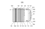
次に図5を用いて交換レンズ100の一つであり、本発明の第2実施例のアクセサリでもある第2の交換レンズ100Bの外観について説明する。図5は第2の交換レンズ100Bの外観を示す図であり、図5Aは光軸Oと直交する第1の方向視における第2の交換レンズ100Bの外観図である。図5Bは光軸Oと直交するとともに第1の方向とは異なる第2の方向視における第2の交換レンズ100Bの外観図である。前述の第1の交換レンズ100Aと同じ機能を有する部品については図2と同じ符号を付し、その説明を省略する。(Second embodiment)
Next, the appearance of a second
第2の交換レンズ100Bにおいても、フォーカス操作リング103の表面には平目状の溝構造(第1の構造)が設けられており、カスタム操作リング104の表面にはアヤ目状の溝構造(第2の構造)が設けられている。このため、本実施例においても、2つの操作部材を識別しやすいアクセサリを実現することが可能である。
In the second
120は図1中のズームレンズユニットZLUを光軸方向に移動させるためのズーム操作リング(第3の操作部材)である。ズーム操作リング120はフォーカス操作リング103よりも像側に設けられている。つまり、物体側から順に、カスタム操作リング104、フォーカス操作リング103、ズーム操作リング120の順に配置されている。
また、図5に示すように、ズーム操作リング120の表面にはフォーカス操作リング103の表面と同様に平目状の溝構造が設けられている。ただし、フォーカス操作リング103とズーム操作リング120の外径形状は異なる。より詳細には、ズーム操作リング120は大径部121と、大径部121よりも径が小さい小径部123と、大径部121と小径部123の間の連結部122を備えている。大径部121、連結部122、小径部123の各表面には平目状の溝構造が設けられている。このため、第2の交換レンズ100Bにおいては、カスタム操作リング104、フォーカス操作リング103、ズーム操作リング120の合計3つの操作リングを識別しやすくなっている。
Further, as shown in FIG. 5, the surface of the
第2の交換レンズ100Bにおいてはズーム操作リング120を操作すると、レンズ保持枠130が光軸方向へ移動する。113はズーム操作リング120の操作をロックして未使用時にレンズ保持枠130が自重で光軸方向へ移動しないようにするためのロックスイッチである。図5Aに示すようにロックスイッチ113の一部を通るとともに光軸Oと平行な直線L4は第2の壁部1072の一部(第1の壁部1071の間の凹部の一部)を通る。したがって、前述のフォーカスモード設定スイッチ110および撮影距離範囲設定スイッチ111と同様に、ロックスイッチ113も探しやすい。
When the
114は手振れ補正機能のオンとオフを切り替えるためのIS切替スイッチである。図5Bに示すように、IS切替スイッチ114の一部を通るとともに光軸Oと平行な直線L5は第2の壁部1072の一部(第1の壁部1071の間の凹部の一部)を通る。したがって、前述のスイッチ110および111と同様に、IS切替スイッチ114も探しやすい。
なお、第2の交換レンズ100Bにおいてキャップ取付指標1091は第2の円環部材1062ではなくレンズ保持枠130に設けられている。
Incidentally, in the second
また、第2の交換レンズ100Bにおいては、フォーカスモード設定スイッチ110、ロックスイッチ113、IS切替スイッチ114はズーム操作リング120よりも像側に設けられている。ズーム操作リング120の表面の素材はフォーカス操作リング103の表面の素材と同様にゴムである。
Further, in the second
(第3実施例)
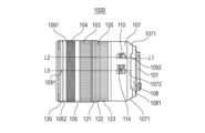
次に図6を用いて交換レンズ100の一つであり、本発明の第3実施例のアクセサリでもある第3の交換レンズ100Cの外観について説明する。図6は第3の交換レンズ100Cの外観を示す図であり、図6Aは光軸Oと直交する第1の方向視における第3の交換レンズ100Cの外観図である。図6Bは光軸Oと直交するとともに第1の方向とは異なる第2の方向視における第2の交換レンズ100Cの外観図である。前述の第1の交換レンズ100Aあるいは第2の交換レンズ100Bと同じ機能を有する部品については図2あるいは図5と同じ符号を付し、その説明を省略する。(Third embodiment)
Next, the external appearance of a third
第3の交換レンズ100Cにおいても、フォーカス操作リング103の表面には平目状の溝構造(第1の構造)が設けられており、カスタム操作リング104の表面にはアヤ目状の溝構造(第2の構造)が設けられている。このため、本実施例においても、2つの操作部材を識別しやすいアクセサリを実現することが可能である。
In the third
前述の第2の交換レンズ100Bと同様に、第3の交換レンズ100Cはズーム操作リング120を備えている。ただし、第3の交換レンズ100Cにおけるズーム操作リング120の光軸方向の位置は第2の交換レンズ100Bとは異なる。具体的には、第3の交換レンズ100Cにおいてズーム操作リング120はフォーカスモード設定スイッチ110よりも像側に設けられている。言い換えれば、第3の交換レンズ100Cにおいてはフォーカス操作リング103とズーム操作リング120の間にフォーカスモード設定スイッチ110が設けられている。
The third
上記の構成を採用することで、第3の交換レンズ100Cのようにフォーカス操作リング103とズーム操作リング120の形状が似ている場合であっても、フォーカスモード設定スイッチ110を境界として両者を識別しやすくなる。そして、前述のようにカスタム操作リング104の表面には他の操作リングとは異なるアヤ目状の溝構造が設けられている。つまり、第3の交換レンズ100Cにおいても、カスタム操作リング104、フォーカス操作リング103、ズーム操作リング120の合計3つの操作リングを識別しやすくなっている。また、第3の交換レンズ100Cにおいては、ズーム操作リング120の径よりもカスタム操作リング104の径の方が大きくなっている。このため、カスタム操作リング104とズーム操作リング120を識別しやすくなっている。
By adopting the above configuration, even when the shapes of the
(第4実施例)
次に図7を用いて交換レンズ100の一つであり、本発明の第4実施例のアクセサリでもある第4の交換レンズ100Dの外観について説明する。図7は第4の交換レンズ100Dの外観を示す図であり、図7Aは光軸Oと直交する第1の方向視における第4の交換レンズ100Dの外観図である。図7Bは光軸Oと直交するとともに第1の方向とは異なる第2の方向視における第4の交換レンズ100Dの外観図である。前述の各交換レンズと同じ機能を有する部品については図2あるいは図5と同じ符号を付し、その説明を省略する。(Fourth embodiment)
Next, the appearance of a fourth
第4の交換レンズ100Dは、前述の第1、第2、第3の交換レンズと異なり、第1の円環部材1061の代わりに第3の円環部材1063を有している。また、キャップ取付指標1091は設けられていない。前述の第1の円環部材1061の表面は赤色であったが、第3の円環部材1063は赤色とは異なる色、例えば、黒色や灰色である。
The fourth
第4の交換レンズ100Dにおいても、フォーカス操作リング103の表面には平目状の溝構造(第1の構造)が設けられており、カスタム操作リング104の表面にはアヤ目状の溝構造(第2の構造)が設けられている。このため、本実施例においても、2つの操作部材を識別しやすいアクセサリを実現することが可能である。
In the fourth
(第5実施例)
次に図8および図9を用いて、本発明の第5実施例のアクセサリであるアダプタ(アクセサリ)400について説明する。図8はアダプタ400を含むカメラシステム300Aの模式図であり、図9はアダプタ400の外観図である。(Fifth embodiment)
Next, an adapter (accessory) 400, which is an accessory according to a fifth embodiment of the present invention, will be described with reference to FIGS. 8 and 9. FIG. FIG. 8 is a schematic diagram of a
前述の各交換レンズ100A~100Dはアダプタを介することなく直接カメラボディ200に装着することが可能である。本実施例におけるアダプタ400も直接カメラボディ200に装着することが可能である。アダプタ400は、図8に示すように、カメラボディ200に直接装着することができない交換レンズ500をカメラボディ200と組み合わせて使用することができるようにするためのアダプタである。
Each of the
図9に示すように、アダプタ400は前述のカスタム操作リング104、レンズ取付指標1092、レンズマウント101を備えている。さらに、交換レンズ500のレンズマウント部に設けられた凹部に挿入するためのロックピン401と、ロックピン401を光軸方向に進退させるためのピン操作部402を備えている。
As shown in FIG. 9, the
図8に示すように、交換レンズ500は、平目状の溝構造を有するフォーカス操作リング103を備えている。そして、図8および図9に示すようにアダプタ400は、アヤ目状の溝構造を有するカスタム操作リング104を備えている。このため、交換レンズ500、アダプタ400、カメラボディ200を用いて撮影を行う場合に交換レンズ500に設けられたフォーカス操作リング103とアダプタ400に設けられたカスタム操作リング104を容易に識別することができる。
As shown in FIG. 8, the
(変形例)
以上、本発明の好ましい実施例について説明したが、本発明はこれらの実施例に限定されないことはいうまでもなく、その要旨の範囲内で種々の変形及び変更が可能である。(Modification)
Although the preferred embodiments of the present invention have been described above, it goes without saying that the present invention is not limited to these embodiments, and various modifications and changes are possible within the scope of the gist of the invention.
前述の第1、第2、第3実施例における各交換レンズは、第2の円環部材1062と、交換レンズの種類を示す指標部材である第1の円環部材1061を有している。しかしながら、第1の円環部材101の代わりに、例えば、第2の円環部材1062の一部を全周にわたって塗装した部分を交換レンズの種類を示す指標としてもよい。
Each of the interchangeable lenses in the first, second, and third embodiments described above has a second
また、前述の第1、第2、第3、第4実施例における交換レンズ(アクセサリ)は互いに異なる部材であり、互いに表面の色が異なる第1の外装部材107と第2の外装部材108を備えている。しかしながら、本発明はこのような構成に限定されるものではない。例えば、第1の外装部材107と第2の外装部材108の代わりにこれらの外装部材が一体となった1つの外装部材を用いてもよい。そして、この1つの外装部材の表面のうち第1の領域の色と、第1の領域とは異なる第2の領域の色とを互いに異ならせてもよい。言い換えれば、第1、第2、第3、第4実施例における交換レンズ(アクセサリ)は、外装部材の表面のうち第1の領域の色と、第1の領域とは異なる第2の領域の色とが互いに異なっていればよい。第1、第2、第3、第4実施例における交換レンズにおいては、第1の領域が第1の外装部材107の表面の領域に相当し、第2の領域が第2の外装部材108の表面の領域に相当する。
Also, the interchangeable lenses (accessories) in the first, second, third, and fourth embodiments described above are members different from each other. I have. However, the present invention is not limited to such a configuration. For example, instead of the
また、前述の第1、第2、第3、第4実施例における交換レンズ(アクセサリ)においては、カスタム操作リング104はフォーカス操作リング103よりも物体側に設けられている。しかしながら、本発明はこのような構成に限定されるものではない。カスタム操作リング104をフォーカス操作リング103よりも像側に設けてもよい。さらに、カスタム操作リング104をズーム操作リング120よりも像側に設けてもよい。
Further, in the interchangeable lenses (accessories) in the first, second, third, and fourth embodiments described above, the
本発明は上記実施の形態に制限されるものではなく、本発明の精神及び範囲から離脱することなく、様々な変更及び変形が可能である。従って、本発明の範囲を公にするために以下の請求項を添付する。
The present invention is not limited to the embodiments described above, and various modifications and variations are possible without departing from the spirit and scope of the present invention. Accordingly, the following claims are included to publicize the scope of the invention.
Claims (23)
ズームのために前記光軸方向に移動するズームレンズユニットと、
前記フォーカスレンズユニットを前記光軸方向に移動させるために操作される第1の操作部材と、
フォーカスとは異なる複数の種類のパラメータから選択的に割り当てられたパラメータを調整するために操作される第2の操作部材と、
前記ズームレンズユニットを前記光軸方向に移動させるために操作される第3の操作部材とを備えるアクセサリであって、
前記第1の操作部材の前記光軸方向の幅は、前記第2の操作部材の前記光軸方向の幅よりも広く、
前記第1の操作部材および前記第3の操作部材の表面の材料はゴムであり、前記第2の操作部材の表面の材料はプラスチックであり、
前記第1の操作部材、および前記第3の操作部材の表面には平目状の溝構造が設けられており、前記第2の操作部材の表面には網目状の溝構造が設けられており、
前記第3の操作部材の平目状の溝構造のピッチが第1の操作部材の平目状の溝構造のピッチよりも大きいことを特徴とするアクセサリ。 a focus lens unit that moves in the optical axis direction for focusing;
a zoom lens unit that moves in the optical axis direction for zooming;
a first operation member operated to move the focus lens unit in the optical axis direction;
a second operating member operated to adjust a parameter selectively assigned from a plurality of types of parameters different from focus;
and a third operating member operated to move the zoom lens unit in the optical axis direction ,
the width of the first operation member in the optical axis direction is wider than the width of the second operation member in the optical axis direction;
The surface material of the first operating member and the third operating member is rubber, and the surface material of the second operating member is plastic,
A flat groove structure is provided on the surfaces of the first operating member and the third operating member , and a mesh-like groove structure is provided on the surface of the second operating member,
An accessory , wherein the pitch of the flat groove structure of the third operating member is larger than the pitch of the flat groove structure of the first operating member.
前記フォーカスモード切替部は前記第3の操作部材よりも像側に設けられていることを特徴とする請求項1乃至3の何れか一項に記載のアクセサリ。 Equipped with a focus mode switching section for switching between autofocus mode and manual focus mode,
4. The accessory according to any one of claims 1 to 3, wherein the focus mode switching section is provided closer to the image side than the third operation member.
前記フォーカスモード切替部は、前記第1の操作部材と前記第3の操作部材の間に設けられていることを特徴とする請求項1乃至3のいずれか一項に記載のアクセサリ。 Equipped with a focus mode switching section for switching between autofocus mode and manual focus mode,
4. The accessory according to any one of claims 1 to 3 , wherein the focus mode switching section is provided between the first operating member and the third operating member.
前記第1の操作部材は、前記第2の操作部材と前記フォーカスモード切替部との間に設けられていることを特徴とする請求項1乃至3のいずれか一項に記載のアクセサリ。4. The accessory according to any one of claims 1 to 3, wherein the first operating member is provided between the second operating member and the focus mode switching section.
前記第1の外装部材から少なくとも一部が露出しているとともに前記第1の外装部材と表面の色が異なる第2の外装部材を備えることを特徴とする請求項1乃至10のいずれか一項に記載のアクセサリ。 a first exterior member;
11. A second exterior member having a surface color different from that of the first exterior member, the second exterior member being at least partly exposed from the first exterior member. accessories described in .
前記第1の方向視及び前記第2の方向視において、前記第1の壁部の前記像側の端面は前記第2の壁部の前記像側の端面よりも前記像側に位置していることを特徴とする請求項12に記載のアクセサリ。 The first exterior member covers a portion of the second exterior member and has a first wall portion and a second wall portion having different image-side end surface positions in the optical axis direction,
When viewed from the first direction and when viewed from the second direction, the image-side end surface of the first wall portion is located closer to the image side than the image-side end surface of the second wall portion. 13. The accessory according to claim 12 , characterized in that:
前記フォーカスモード切替部は、前記第2の方向視において、前記光軸方向と平行な方向に延びる所定の直線が前記フォーカスモード切替部と前記第2の壁部とを通るように配置されていることを特徴とする請求項13に記載のアクセサリ。 Equipped with a focus mode switching unit for switching between autofocus mode and manual focus mode,
The focus mode switching portion is arranged such that a predetermined straight line extending in a direction parallel to the optical axis direction passes through the focus mode switching portion and the second wall portion when viewed from the second direction. 14. An accessory according to claim 13 , characterized in that:
前記取付指標は、前記第2の方向視において、前記光軸方向と平行な方向に延びる所定の直線が前記取付指標と前記第2の壁部を通るように配置されていることを特徴とする請求項13または14に記載のアクセサリ。 The second exterior member is provided with an attachment index,
The mounting index is arranged such that a predetermined straight line extending in a direction parallel to the optical axis direction passes through the mounting index and the second wall when viewed from the second direction. 15. Accessory according to claim 13 or 14 .
前記中間筒は光軸回りに回転しないことを特徴とする請求項1乃至15のいずれか一項に記載のアクセサリ。 An intermediate cylinder provided between the second operating member and the first operating member,
16. An accessory as claimed in any one of the preceding claims, wherein the intermediate barrel does not rotate around the optical axis.
前記第2の操作部材を操作する際には前記クリック感発生機構によってクリック感が発生することを特徴とする請求項18に記載のアクセサリ。 A click feeling does not occur when the first operation member is operated,
19. The accessory according to claim 18 , wherein a click feeling is generated by the click feeling generating mechanism when the second operating member is operated.
前記選択的に割り当てられたパラメータは前記複数の種類のパラメータのうち前記選択手段によって選択されたパラメータであることを特徴とする請求項1乃至20のいずれか一項に記載のアクセサリ。 The accessory is detachable from a camera body having an imaging element and a selection means,
21. An accessory according to any preceding claim, wherein said selectively assigned parameter is a parameter selected by said selection means from said plurality of types of parameters.
撮像素子を保持するカメラ本体と、を備えることを特徴とするカメラシステム。 an accessory according to any one of claims 1 to 22 ;
A camera system comprising: a camera body that holds an imaging element.
Priority Applications (2)
| Application Number | Priority Date | Filing Date | Title |
|---|---|---|---|
| JP2023094139A JP2023111977A (en) | 2018-08-10 | 2023-06-07 | Accessory and camera system including the same |
| JP2023094140A JP2023111978A (en) | 2018-08-10 | 2023-06-07 | Accessory and camera system including the same |
Applications Claiming Priority (1)
| Application Number | Priority Date | Filing Date | Title |
|---|---|---|---|
| PCT/JP2018/030072 WO2020031374A1 (en) | 2018-08-10 | 2018-08-10 | Accessory and camera system with same |
Related Child Applications (2)
| Application Number | Title | Priority Date | Filing Date |
|---|---|---|---|
| JP2023094140A Division JP2023111978A (en) | 2018-08-10 | 2023-06-07 | Accessory and camera system including the same |
| JP2023094139A Division JP2023111977A (en) | 2018-08-10 | 2023-06-07 | Accessory and camera system including the same |
Publications (2)
| Publication Number | Publication Date |
|---|---|
| JPWO2020031374A1 JPWO2020031374A1 (en) | 2021-08-12 |
| JP7293232B2 true JP7293232B2 (en) | 2023-06-19 |
Family
ID=69414577
Family Applications (3)
| Application Number | Title | Priority Date | Filing Date |
|---|---|---|---|
| JP2020535466A Active JP7293232B2 (en) | 2018-08-10 | 2018-08-10 | Accessories and camera systems equipped with them |
| JP2023094140A Pending JP2023111978A (en) | 2018-08-10 | 2023-06-07 | Accessory and camera system including the same |
| JP2023094139A Pending JP2023111977A (en) | 2018-08-10 | 2023-06-07 | Accessory and camera system including the same |
Family Applications After (2)
| Application Number | Title | Priority Date | Filing Date |
|---|---|---|---|
| JP2023094140A Pending JP2023111978A (en) | 2018-08-10 | 2023-06-07 | Accessory and camera system including the same |
| JP2023094139A Pending JP2023111977A (en) | 2018-08-10 | 2023-06-07 | Accessory and camera system including the same |
Country Status (6)
| Country | Link |
|---|---|
| US (1) | US20210157091A1 (en) |
| EP (2) | EP3835842A4 (en) |
| JP (3) | JP7293232B2 (en) |
| CN (2) | CN117849981A (en) |
| TW (2) | TWI772665B (en) |
| WO (1) | WO2020031374A1 (en) |
Families Citing this family (3)
| Publication number | Priority date | Publication date | Assignee | Title |
|---|---|---|---|---|
| WO2020031374A1 (en) | 2018-08-10 | 2020-02-13 | キヤノン株式会社 | Accessory and camera system with same |
| US20230375901A1 (en) * | 2020-03-24 | 2023-11-23 | Samyang Optics Co., Ltd | Camera lens assembly having user-designated functions |
| WO2023054011A1 (en) * | 2021-09-28 | 2023-04-06 | 富士フイルム株式会社 | Lens barrel |
Citations (6)
| Publication number | Priority date | Publication date | Assignee | Title |
|---|---|---|---|---|
| JP2003177294A (en) | 2001-12-13 | 2003-06-27 | Nikon Corp | Lens barrel, accessory, image pickup device main body and image pickup system |
| JP2011017774A (en) | 2009-07-07 | 2011-01-27 | Nikon Corp | Lens barrel and optical apparatus |
| JP2011090023A (en) | 2009-10-20 | 2011-05-06 | Nikon Corp | Lens barrel |
| WO2013031407A1 (en) | 2011-08-31 | 2013-03-07 | 富士フイルム株式会社 | Lens device and imaging device having said lens device |
| WO2017047592A1 (en) | 2015-09-15 | 2017-03-23 | 富士フイルム株式会社 | Lens barrel and imaging device |
| JP2018102714A (en) | 2016-12-27 | 2018-07-05 | オリンパス株式会社 | Optical adapter for endoscope and endoscope apparatus |
Family Cites Families (22)
| Publication number | Priority date | Publication date | Assignee | Title |
|---|---|---|---|---|
| JPH09159900A (en) * | 1995-12-07 | 1997-06-20 | Nikon Corp | Lens barrel |
| JPH09281376A (en) * | 1996-04-11 | 1997-10-31 | Nikon Corp | Lens barrel |
| JPH09318993A (en) * | 1996-05-30 | 1997-12-12 | Canon Inc | Solid-state image pickup element camera system, interchangeable lens for photographing and optical accessory |
| US6381076B1 (en) * | 2000-09-26 | 2002-04-30 | Canon Kabushiki Kaisha | Zoom lens barrel |
| JP3870183B2 (en) * | 2003-08-01 | 2007-01-17 | キヤノン株式会社 | Intermediate adapter and camera system |
| DE102004009856A1 (en) * | 2004-02-25 | 2005-09-22 | Arnold & Richter Cine Technik Gmbh & Co Betriebs Kg | Device for connecting a camera lens to a motion picture camera |
| JP5328526B2 (en) * | 2009-07-03 | 2013-10-30 | キヤノン株式会社 | Imaging device |
| TWI438482B (en) * | 2009-07-17 | 2014-05-21 | Hon Hai Prec Ind Co Ltd | Camera module |
| EP2696230A4 (en) * | 2011-04-02 | 2014-08-27 | Jin Luo | Additional knurled ring for optical lens |
| JP5418552B2 (en) * | 2011-07-22 | 2014-02-19 | 株式会社ニコン | Adapter, camera system, and adapter control program |
| JP6013772B2 (en) * | 2011-08-23 | 2016-10-25 | パナソニックIpマネジメント株式会社 | Interchangeable lens and camera body |
| WO2013027315A1 (en) * | 2011-08-25 | 2013-02-28 | パナソニック株式会社 | Lens barrel |
| JP2013092583A (en) * | 2011-10-24 | 2013-05-16 | Olympus Imaging Corp | Photographing apparatus and optical device |
| CN103091812A (en) * | 2011-11-04 | 2013-05-08 | 华晶科技股份有限公司 | Lens of improving focusing accuracy rates and photographic device thereof |
| RU2756433C2 (en) * | 2011-11-11 | 2021-09-30 | Никон Корпорейшн | Focus adjustment device, image forming device and lens |
| TWI448769B (en) * | 2011-11-29 | 2014-08-11 | Altek Corp | Zooming of lens mechanism and image pickup device using the same |
| EP2950126B1 (en) * | 2013-01-25 | 2018-11-07 | Olympus Corporation | Lens barrel |
| WO2016052418A1 (en) * | 2014-09-29 | 2016-04-07 | 富士フイルム株式会社 | Lens barrel, camera main body, and photographing device |
| JP6456216B2 (en) * | 2015-02-27 | 2019-01-23 | 株式会社吉野工業所 | Threaded cap container |
| US9952483B2 (en) * | 2015-10-28 | 2018-04-24 | BAND.IT.Co. | Customizable elastic collar grip for enhanced manual manipulation of camera lenses |
| CN208401966U (en) * | 2018-01-13 | 2019-01-18 | 刘仁瑞 | A kind of drawer type motion cameras |
| WO2020031374A1 (en) | 2018-08-10 | 2020-02-13 | キヤノン株式会社 | Accessory and camera system with same |
-
2018
- 2018-08-10 WO PCT/JP2018/030072 patent/WO2020031374A1/en unknown
- 2018-08-10 EP EP18929099.2A patent/EP3835842A4/en active Pending
- 2018-08-10 EP EP22193847.5A patent/EP4137857A1/en active Pending
- 2018-08-10 CN CN202410067628.7A patent/CN117849981A/en active Pending
- 2018-08-10 CN CN201880096627.8A patent/CN112567275A/en active Pending
- 2018-08-10 JP JP2020535466A patent/JP7293232B2/en active Active
-
2019
- 2019-08-08 TW TW108128312A patent/TWI772665B/en active
- 2019-08-08 TW TW111125307A patent/TWI828224B/en active
-
2021
- 2021-02-02 US US17/165,768 patent/US20210157091A1/en active Pending
-
2023
- 2023-06-07 JP JP2023094140A patent/JP2023111978A/en active Pending
- 2023-06-07 JP JP2023094139A patent/JP2023111977A/en active Pending
Patent Citations (6)
| Publication number | Priority date | Publication date | Assignee | Title |
|---|---|---|---|---|
| JP2003177294A (en) | 2001-12-13 | 2003-06-27 | Nikon Corp | Lens barrel, accessory, image pickup device main body and image pickup system |
| JP2011017774A (en) | 2009-07-07 | 2011-01-27 | Nikon Corp | Lens barrel and optical apparatus |
| JP2011090023A (en) | 2009-10-20 | 2011-05-06 | Nikon Corp | Lens barrel |
| WO2013031407A1 (en) | 2011-08-31 | 2013-03-07 | 富士フイルム株式会社 | Lens device and imaging device having said lens device |
| WO2017047592A1 (en) | 2015-09-15 | 2017-03-23 | 富士フイルム株式会社 | Lens barrel and imaging device |
| JP2018102714A (en) | 2016-12-27 | 2018-07-05 | オリンパス株式会社 | Optical adapter for endoscope and endoscope apparatus |
Also Published As
| Publication number | Publication date |
|---|---|
| TWI772665B (en) | 2022-08-01 |
| EP3835842A1 (en) | 2021-06-16 |
| TWI828224B (en) | 2024-01-01 |
| EP3835842A4 (en) | 2022-03-23 |
| TW202240226A (en) | 2022-10-16 |
| US20210157091A1 (en) | 2021-05-27 |
| JP2023111977A (en) | 2023-08-10 |
| JPWO2020031374A1 (en) | 2021-08-12 |
| WO2020031374A1 (en) | 2020-02-13 |
| CN117849981A (en) | 2024-04-09 |
| EP4137857A1 (en) | 2023-02-22 |
| JP2023111978A (en) | 2023-08-10 |
| CN112567275A (en) | 2021-03-26 |
| TW202009535A (en) | 2020-03-01 |
Similar Documents
| Publication | Publication Date | Title |
|---|---|---|
| JP2023111977A (en) | Accessory and camera system including the same | |
| US20110267526A1 (en) | Camera | |
| WO2018062208A1 (en) | Camera system, lens unit, and camera body | |
| JP2013057837A (en) | Camera system and interchangeable lens | |
| US8559807B2 (en) | Camera system and lens barrel | |
| US8553136B2 (en) | Camera system | |
| WO2018020789A1 (en) | Camera, camera setting method, and camera setting program | |
| JP2023027993A (en) | Electronic device | |
| JP2014092565A (en) | Interchangeable lens barrel | |
| JP2008175897A (en) | Optical lens detecting structure, detachable structure and photographing device provided with them | |
| US8885267B2 (en) | Lens barrel and image pickup apparatus | |
| JP5969847B2 (en) | Imaging device | |
| US11550207B2 (en) | Image capturing apparatus, accessory, camera system including image capturing apparatus and accessory | |
| JP2007017746A (en) | Imaging system, camera main body and lens | |
| WO2015170434A1 (en) | Rotating display unit for imaging unit | |
| JP3761999B2 (en) | Information input device for optical equipment | |
| JP7247009B2 (en) | Imaging device with vibration device | |
| JP7187230B2 (en) | Electronic equipment with vibration device | |
| JP2004294685A (en) | Television lens | |
| WO2023228697A1 (en) | Lens device, imaging device, and lens driving method | |
| WO2023204100A1 (en) | Optical device | |
| US11256162B2 (en) | Operation apparatus, lens apparatus, and image pickup apparatus | |
| JP7191612B2 (en) | Electronic equipment with vibration device | |
| US20140132815A1 (en) | Digital camera structure capable of selectively mounting a camera lens | |
| JP2019105814A (en) | Lens device and imaging apparatus including the same |
Legal Events
| Date | Code | Title | Description |
|---|---|---|---|
| A524 | Written submission of copy of amendment under article 19 pct |
Free format text: JAPANESE INTERMEDIATE CODE: A527 Effective date: 20201214 |
|
| A621 | Written request for application examination |
Free format text: JAPANESE INTERMEDIATE CODE: A621 Effective date: 20210730 |
|
| A131 | Notification of reasons for refusal |
Free format text: JAPANESE INTERMEDIATE CODE: A131 Effective date: 20220830 |
|
| A521 | Request for written amendment filed |
Free format text: JAPANESE INTERMEDIATE CODE: A523 Effective date: 20221031 |
|
| A131 | Notification of reasons for refusal |
Free format text: JAPANESE INTERMEDIATE CODE: A131 Effective date: 20221220 |
|
| A521 | Request for written amendment filed |
Free format text: JAPANESE INTERMEDIATE CODE: A523 Effective date: 20230217 |
|
| TRDD | Decision of grant or rejection written | ||
| A01 | Written decision to grant a patent or to grant a registration (utility model) |
Free format text: JAPANESE INTERMEDIATE CODE: A01 Effective date: 20230509 |
|
| A61 | First payment of annual fees (during grant procedure) |
Free format text: JAPANESE INTERMEDIATE CODE: A61 Effective date: 20230607 |
|
| R151 | Written notification of patent or utility model registration |
Ref document number: 7293232 Country of ref document: JP Free format text: JAPANESE INTERMEDIATE CODE: R151 |