JP5969847B2 - Imaging device - Google Patents
Imaging device Download PDFInfo
- Publication number
- JP5969847B2 JP5969847B2 JP2012160515A JP2012160515A JP5969847B2 JP 5969847 B2 JP5969847 B2 JP 5969847B2 JP 2012160515 A JP2012160515 A JP 2012160515A JP 2012160515 A JP2012160515 A JP 2012160515A JP 5969847 B2 JP5969847 B2 JP 5969847B2
- Authority
- JP
- Japan
- Prior art keywords
- unit
- display
- display unit
- image
- control unit
- Prior art date
- Legal status (The legal status is an assumption and is not a legal conclusion. Google has not performed a legal analysis and makes no representation as to the accuracy of the status listed.)
- Expired - Fee Related
Links
Images


Description
本発明は、撮像装置に関する。 The present invention relates to an imaging apparatus.
一般に、カメラには、外付けのストロボやファインダや通信機器など、種々の外部接続機器が接続されることがある。一方で、例えば特許文献1には、自分撮りをするために、撮像部や表示部が回動する撮像装置に係る技術が開示されている。このように、外部接続機器やカメラ本体の各部と表示部とは、様々な位置関係を取り得る。 In general, various external connection devices such as an external strobe, a finder, and a communication device may be connected to the camera. On the other hand, for example, Patent Document 1 discloses a technique related to an imaging device in which an imaging unit and a display unit rotate in order to take a self-portrait. In this way, the external connection device and each part of the camera body and the display part can take various positional relationships.
カメラ本体に接続された外部接続機器やカメラ本体の各部とカメラ本体に設けられた表示部との位置関係によっては、撮影者から見て表示部が外部接続機器やカメラ本体の一部によって隠されて、撮影者にとって表示部の視認性が悪くなることがある。 Depending on the external connection device connected to the camera body and the positional relationship between each part of the camera body and the display part provided on the camera body, the display part is hidden by the external connection device and part of the camera body as viewed from the photographer. Therefore, the visibility of the display unit may be deteriorated for the photographer.
そこで本発明は、表示部の視認性が確保される撮像装置を提供することを目的とする。 SUMMARY OF THE INVENTION An object of the present invention is to provide an imaging device that ensures the visibility of a display unit.
前記目的を果たすため、本発明の一態様によれば、撮像装置は、被写体画像を取得する撮像部と、前記被写体画像を表示する表示部と、接続された外部機器から、少なくとも前記外部機器の大きさに関するデータを取得するとともに、前記外部機器を判定する接続機器判定部と、前記取得された外部機器の大きさに関するデータに加え、前記表示部の表示面の一部を遮蔽する関係になる前記外部機器と前記表示部との位置関係を取得し、前記表示部の表示領域のうち前記外部機器によって遮られない有効表示範囲を判定する領域判定部と、前記有効表示範囲に前記被写体画像を表示させる表示制御部とを具備する。
In order to achieve the above object, according to one aspect of the present invention, an imaging apparatus includes at least an external device from an imaging unit that acquires a subject image, a display unit that displays the subject image, and a connected external device. In addition to acquiring data related to the size, in addition to the connected device determination unit that determines the external device and the acquired data related to the size of the external device, a part of the display surface of the display unit is shielded. An area determination unit that acquires a positional relationship between the external device and the display unit , determines an effective display range that is not obstructed by the external device , and displays the subject image in the effective display range. A display control unit for displaying.
本発明によれば、表示部の視認性が確保される撮像装置を提供できる。 ADVANTAGE OF THE INVENTION According to this invention, the imaging device with which the visibility of a display part is ensured can be provided.
[第1の実施形態]
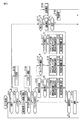
本発明の第1の実施形態について図面を参照して説明する。本実施形態に係る撮像装置としてのデジタルカメラ1の概略を図1に示す。デジタルカメラ1は、例えば、レンズ交換式のカメラである。ただし、レンズ交換式に限る必要はなく、レンズが固定されたカメラにも本実施形態に係る技術は適用され得る。
[First Embodiment]
A first embodiment of the present invention will be described with reference to the drawings. An outline of a digital camera 1 as an imaging apparatus according to the present embodiment is shown in FIG. The digital camera 1 is, for example, a lens interchangeable camera. However, the present invention is not limited to the interchangeable lens type, and the technology according to the present embodiment can be applied to a camera in which a lens is fixed.
レンズ交換式のデジタルカメラ1は、カメラ本体10と、レンズ20と、ファインダ部30とを有する。ユーザは、カメラ本体10に好みのレンズ20を取り付けて撮影を行う。レンズ20は、被写体像を後述するカメラ本体10に設けられた撮像素子12に導く。ここでは、レンズ20は、ズームレンズであるものとして説明を行う。レンズ20は、レンズ光学系26を有する。レンズ光学系26には、ズーム部26aと、ピント部26bと、絞り部26cとが設けられている。ズーム部26aは、複数のレンズ要素の位置を移動させてズーム機能を実現する。ピント部26bは、ピント合わせ用レンズを移動させて、被写体像を撮像素子12に合焦させる。絞り部26cは、絞りの開閉動作をすることで、撮像素子12に導かれる光の量を調整する。
The interchangeable lens digital camera 1 includes a
レンズ20は、ズーム部26a、ピント部26b、絞り部26c等の動作を制御する制御部21を有する。また、レンズ20は、ズーム部26a内の各要素の位置を検出する位置検出部25aと、ピント部26b内の各要素の位置を検出する位置検出部25bと、絞り部26c内の各要素の位置を検出する位置検出部25cとを有する。また、レンズ20は、ズーム部26a内のモータ等を駆動する駆動部24aと、ピント部26b内のモータ等を駆動する駆動部24bと、絞り部26c内のモータ等を駆動する駆動部24cとを有する。また、レンズ20は、レンズ特性や制御データやプログラム等を記録している記憶部27を有する。また、記憶部27には、レンズの大きさに係る情報も記録されている。さらにレンズ20は、カメラ本体10と通信するための本体通信部22とを有する。
The
制御部21は、記憶部27に記録された制御データやプログラム、本体通信部22を介して取得された各種制御パラメータに基づき、位置検出部25aの出力を利用して、駆動部24aを動作させ、ズーム部26aを駆動する。また、制御部21は、記憶部27に記録された制御データやプログラム、本体通信部22を介して取得された各種制御パラメータに基づき、位置検出部25bの出力を利用して、駆動部24bを動作させ、ピント部26bを駆動する。また、制御部21は、記憶部27に記録された制御データやプログラム、本体通信部22を介して取得された各種制御パラメータに基づき、位置検出部25cの出力を利用して、駆動部24cを動作させ、絞り部26cを駆動する。
The
また、レンズ20は、操作部23a及び操作部23bを有する。操作部23a及び操作部23bは、ズーム部26a、ピント部26b、絞り部26c等の動作を入力するための操作部である。ユーザは、操作部23a及び操作部23bを操作することで、ズーム部26a、ピント部26b、絞り部26c等の動作を調整することができる。例えば操作部23a及び操作部23bは、鏡筒に沿って回動するリング部を有している。リング部は、シフト操作も可能である。例えば、回転動作が操作部23aの入力に対応し、シフト動作が操作部23bの入力に対応する。なお、操作部23a及び操作部23bは、操作スイッチなどでもよい。
The
例えばズームリングである操作部23aは、ズーム部26aとギアやカムを用いて機械的には連携していない。本実施形態のレンズ20では、操作部23aの操作に応じて、例えば小型アクチュエータやメカトロニクス技術を用いた駆動部24aの機構によって、ズーム部26aが駆動される。
For example, the
一方、カメラ本体10は、各種信号を処理し、カメラ本体10の各部を制御する信号処理制御部11を有する。信号処理制御部11は、例えば集積回路で構成される。この信号処理制御部11には、後述するように例えば画像の表示や記録に必要な画像処理が可能な信号処理部11aが設けられている。
On the other hand, the
カメラ本体10は、撮像素子12を有する。撮像素子12は、撮像動作をする。すなわち、撮像素子12は、レンズ20から入射した被写体像を電気信号に変換し、画像信号を生成する。撮像素子12は、生成した画像信号を信号処理制御部11に出力する。レンズ光学系26と撮像素子12とによって、撮像部29として機能する部位を形成する。
The
カメラ本体10は、例えばその背面に表示パネル18を有している。表示パネル18は、ヒンジ18cでカメラ本体10と接続されており、ヒンジ18cを軸として、カメラ本体10に対して位置及び姿勢を変化させ得る。ヒンジ18cには、例えばエンコーダといった表示パネル18の位置及び姿勢を検出するための機構が設けられている。例えばエンコーダからは、ヒンジ18cの回転角度に係る情報が信号処理制御部11内の表示部状態判定部11dに出力される。表示パネル18は、画像を表示する表示部18aを有する。表示部18aは、例えば液晶表示パネルを含む。表示部18aには、有機ELパネル等、他の表示用デバイスが用いられてもよい。
The
表示パネル18の表示部18a上には、タッチパネル18bが設けられている。タッチパネル18bはユーザの指示の入力を受け取る。ユーザは、例えば表示部18aに表示されたアイコンに対応する位置を触れることにより、デジタルカメラ1の操作を行うことができる。例えばタッチパネル18bは、注目被写体の入力や、ズーム動作の入力や、露光の調整の入力にも用いられ得る。ユーザによってタッチされたことによりタッチパネル18bが発生する信号は、信号処理制御部11内のタッチ判定部11eに出力され、その信号はまずタッチ判定部11eで処理される。
On the
また、カメラ本体10は、電子ビューファインダ(Electronic View Finder;EVF)等のファインダ部30が取り付けられるように構成されている。ここで、ファインダ部30は、接眼表示部31と本体通信部32と、接眼センサ33とを有している。一方、カメラ本体10は、ファインダ通信部15bを有している。ファインダ部30の本体通信部32とカメラ本体10のファインダ通信部15bとは、接続されて通信を行う。接眼表示部31は、小型の液晶パネル又は有機ELパネル等を有している。ファインダ部30は、表示画像を専用の光学系で拡大してユーザに目視可能にさせるものである。接眼センサ33は、接眼表示部31がユーザによって覗かれているか否かに係る情報を信号処理制御部11に出力する。表示部18a及び接眼表示部31は、信号処理制御部11内の表示制御部11bの制御下で動作する。
The
ファインダ部30によれば、ユーザは、ファインダ部30を覗き込む形で観察できるので、外光の影響を受けずに画像を観察できる。さらに、ファインダ部30は、専用の光学系の調整によって、ユーザの視度に合わせた視度調整ができるように構成されている。この視度調整により、ユーザは、自身の視力に関わらず良好な画像の観察を行うことができる。また、ファインダ部30によれば、ユーザはカメラ本体10を顔の近くに位置させることで、デジタルカメラ1を安定して構えることができる。本実施形態では、ファインダ部30は、カメラ本体10から取り外し可能であるものとして説明するが、カメラ本体10に対して固定されていてもよい。
According to the
カメラ本体10には、スイッチ等、ユーザの様々な操作による入力を受け取る操作部16が設けられている。操作部16は、ユーザの右手の人差し指が配置される位置に設けられたレリーズスイッチを含む。また、操作部16は、シャッタースピード、絞り、露出補正、感度設定、ピント位置等の撮影パラメータの変更が入力されるスイッチやダイヤルや十字キー等を含む。
The
カメラ本体10は、第1の記憶部14aと第2の記憶部14bとを有する。第1の記憶部14aは、例えばROMであり、例えば信号処理制御部11による制御に用いるプログラム等を記憶している。また、第1の記憶部14aには、表示部18aの大きさを含むカメラ本体10の各部の大きさに係る情報などが記憶されている。第2の記憶部14bは、例えばRAMであり、例えば信号処理制御部11による処理結果を一時的に記憶する。さらに、カメラ本体10には、撮影して生成された画像データを記録するための記録部17が設けられている。この記録部17は、一般的な記録媒体として、カメラ本体10に対して取り外し可能に接続されている。
The
また、カメラ本体10は、内臓ストロボ13を有する。例えば内臓ストロボ13は、使用されないときはカメラ本体10に収納され、使用されるときにはカメラ本体10から突出するように構成されている。さらにカメラ本体10には、例えば外付けストロボといった種々のアクセサリ(外部接続機器)40が接続されるようになっており、アクセサリ40と通信するためのアクセサリ通信部19が設けられている。アクセサリ40には、記憶部49が設けられており、アクセサリ40のサイズを含むアクセサリ40に係る各種情報が記憶されている。
The
また、カメラ本体10は、レンズ20の本体通信部22と通信するためのレンズ通信部15aを有する。カメラ本体10からレンズ20へのレンズ20の動作の指示や、レンズ20からカメラ本体10へのレンズ20の状態に係る情報の転送等は、レンズ通信部15aと本体通信部22とを介して行われる。また、カメラ本体10は、撮影した画像に撮影日時のデータを付加する等のため、時計11hを有する。
Further, the
信号処理制御部11は、第1の記憶部14aに記憶されたプログラムに従って動作する。信号処理制御部11には、信号処理部11a、表示制御部11b、接続機器判定部11c、表示部状態判定部11d、タッチ判定部11e、領域判定部11fが設けられている。信号処理制御部11内の信号処理部11aは、ユーザが表示部18aや接眼表示部31を見ながら撮影できるように、撮像素子12から入力された画像信号に基づいてプレビュー画像を作成する。また、信号処理部11aは、例えば操作部16からの入力に応じて、撮影時には撮像素子12から入力された画像信号に基づいて記録画像を作成し、この記録画像を記録部17に記録させる。
The signal processing control unit 11 operates according to a program stored in the
信号処理制御部11内の表示制御部11bは、信号処理部11aが作成したプレビュー画像やその他の画像を、表示部18aや接眼表示部31に表示させる。この際、後述の領域判定部11fが判定した有効表示範囲に各種画像を表示させるように制御する。信号処理制御部11内の接続機器判定部11cは、アクセサリ通信部19を介してカメラ本体10に接続されたアクセサリの大きさ等各種情報を取得する。また、接続機器判定部11cは、レンズ通信部15aを介してレンズ20の大きさ等の情報も取得する。
The
信号処理制御部11内の表示部状態判定部11dは、ヒンジ18cに設けられたエンコーダ等からヒンジ18c周りの回転角度に係る情報等を取得し、カメラ本体10に対する表示パネル18の姿勢等の状態を判定する。信号処理制御部11内のタッチ判定部11eは、タッチパネル18bから信号を取得して、タッチパネル18bを介したユーザの指示を取得する。
The display unit
信号処理制御部11内の領域判定部11fは、第1の記憶部14aからカメラ本体10の情報を取得し、接続機器判定部11cからカメラ本体10に接続されたレンズ20やアクセサリ40の情報を取得し、また、表示部状態判定部11dから表示パネルの姿勢等に係る情報を取得する。領域判定部11fは、取得したこれら情報に基づいて、表示部18aの表示領域のうち、撮影者からみてレンズ20やアクセサリ40に隠されない有効表示範囲を判定する。
The area determination unit 11f in the signal processing control unit 11 acquires information on the
本実施形態に係るデジタルカメラ1の動作を説明する。このデジタルカメラ1の信号処理制御部11によって行われる処理の一例を図2に示されるフローチャートを参照して説明する。ステップS101において信号処理制御部11は、撮影モードであるか否かを判定する。撮影モードであると判定されたとき、処理はステップS102に進む。ステップS102において信号処理制御部11は、レンズ交換が行われたか否かを判定する。レンズ交換が行われたと判定されたとき、処理はステップS103に進む。ステップS103において信号処理制御部11は、レンズの情報を取得する等のレンズ通信を行う。その後、処理はステップS104に進む。ステップS102において、レンズ交換が行われていないと判定されたとき、処理はステップS104に進む。 The operation of the digital camera 1 according to this embodiment will be described. An example of processing performed by the signal processing control unit 11 of the digital camera 1 will be described with reference to a flowchart shown in FIG. In step S101, the signal processing control unit 11 determines whether or not the shooting mode is set. When it is determined that the shooting mode is set, the process proceeds to step S102. In step S102, the signal processing control unit 11 determines whether lens replacement has been performed. When it is determined that the lens has been changed, the process proceeds to step S103. In step S103, the signal processing control unit 11 performs lens communication such as acquiring lens information. Thereafter, the process proceeds to step S104. If it is determined in step S102 that lens replacement has not been performed, the process proceeds to step S104.
ステップS104において信号処理制御部11は、撮像素子12から画像信号を取得する。信号処理制御部11は、この画像信号に基づいて、スルー画を作成する。また、信号処理制御部11は、表示部18aにスルー画を表示させる。ステップS105において信号処理制御部11は、アクセサリが接続されているか否かを判定する。アクセサリが接続されていると判定されたとき、処理はステップS106に進む。ステップS106において信号処理制御部11は、接続されたアクセサリと通信を行い、アクセサリの情報を取得する。その後、処理はステップS107に進む。ステップS105において、アクセサリが接続されていないと判定されたとき、処理はステップS107に進む。
In step S <b> 104, the signal processing control unit 11 acquires an image signal from the image sensor 12. The signal processing control unit 11 creates a through image based on the image signal. In addition, the signal processing control unit 11 displays a through image on the
ステップS107において信号処理制御部11は、例えばヒンジ18cに設けられたエンコーダから情報を取得し、表示パネル18の角度が初期状態から変化しているか否かを判定する。角度が初期状態から変化していないと判定されたとき、処理はステップS130に進む。一方、角度が初期状態から変化していると判定されたとき、処理はステップS110に進む。
In step S107, the signal processing control unit 11 acquires information from, for example, an encoder provided on the
ステップS110において信号処理制御部11は、取得した表示パネル18の角度に基づいて、撮影状態を取得する。ステップS111において信号処理制御部11は、撮影状態が自分撮りであるか否かを判定する。すなわち、表示パネル18が180度上向きに回転し、表示部18aが被写体の方に向いているリバースモニタの状態か否かを判定する。自分撮りであると判定されたとき、処理はステップS112に進む。ステップS112において信号処理制御部11は、接続されたアクセサリのサイズを考慮して、撮像装置正面から見た有効表示範囲を算出する。ここで、有効表示範囲とは、表示部18aの表示面のうち、障害物に邪魔されずに撮影者によって視認できる表示領域である。ステップS113において信号処理制御部11は、表示部18aの有効表示範囲にスルー画を表示させる。その後、処理はステップS130に進む。
In step S <b> 110, the signal processing control unit 11 acquires the shooting state based on the acquired angle of the
ステップS113における表示の概要について、図3を参照して説明する。カメラ本体10にレンズ20とファインダ部30とが装着されたデジタルカメラ1の外観の模式図を図3(a)に示す。自分撮りをするために、表示パネル18をリバースモニタの状態にした模式図を図3(b)に示す。図3(b)の状態では、表示部18aは、何にも隠されることなく、被写体である撮影者から表示領域の全面が見える状態である。そこで、この場合、デジタルカメラ1は、表示部18aの表示面全面を有効表示範囲として、全面にスルー画101を表示させる。なお、表示パネル18はリバースモニタの状態になっているので、表示パネル18が通常の状態になっているときとは表示部18aへの表示が上下反転している。
An overview of the display in step S113 will be described with reference to FIG. FIG. 3A shows a schematic diagram of the external appearance of the digital camera 1 in which the
一方、内臓ストロボ13が用いられるため、内臓ストロボ13がカメラ本体10から突出した状態の模式図を図3(c)に示す。このとき、内臓ストロボ13によって、表示部18aの一部が隠されることになる。すなわち、有効表示範囲が減少する。そこで、この場合、デジタルカメラ1は、表示部18aの内臓ストロボ13が障害とならない有効表示範囲にスルー画102を表示させる。
On the other hand, since the built-in
また、アクセサリとして、外付けストロボ41がカメラ本体10に装着された状態の模式図を図3(d)に示す。このとき、外付けストロボ41によって、表示部18aの多くの部分が隠されることになる。すなわち、有効表示範囲が減少する。そこで、図3(d)の例では、デジタルカメラ1は、表示部18aの外付けストロボ41が障害とならない有効表示範囲にスルー画103を表示させる。この場合では、外付けストロボ41の左右に、有効表示部範囲が存在するので、外付けストロボ41の左右にスルー画103が表示されている。
Also, FIG. 3D shows a schematic diagram of the state in which the
また、外形が大きなレンズ20がカメラ本体10に装着された状態の模式図を図3(e)に示す。このとき、レンズ20によって、表示部18aの一部が隠されることになる。すなわち、有効表示範囲が減少する。そこで、この場合、デジタルカメラ1は、表示部18aのレンズ20が障害とならない有効表示範囲にスルー画104を表示させる。
Further, FIG. 3E shows a schematic diagram of a state in which the
なお、図3に示される例では、ファインダ部30は、表示部18aの表示領域を遮らない。しかしながら、ファインダ部30が装着されることで表示部18aの一部が隠される場合も、上記の各例と同様に、有効表示範囲にスルー画が表示されることになる。
In the example shown in FIG. 3, the
図2に戻って説明を続ける。ステップS111において、自分撮りでないと判定されたとき、処理はステップS114に進む。ステップS114において信号処理制御部11は、撮影状態がローアングル撮影であるか否かを判定する。すなわち、表示パネル18が例えば90度程度上向きに回転している状態か否かを判定する。ローアングル撮影であると判定されたとき、処理はステップS115に進む。ステップS115において信号処理制御部11は、接続されたアクセサリのサイズを考慮して、撮像装置上から見た有効表示範囲を算出する。ステップS116において信号処理制御部11は、表示部18aの有効表示範囲にスルー画を表示させる。その後、処理はステップS130に進む。
Returning to FIG. 2, the description will be continued. If it is determined in step S111 that it is not self-portrait, the process proceeds to step S114. In step S114, the signal processing control unit 11 determines whether or not the shooting state is low angle shooting. That is, it is determined whether or not the
ステップS116における表示の概要について、図4を参照して説明する。アクセサリとして、外付けストロボ41がカメラ本体10に装着された状態の模式図を図4に示す。この例では、撮影者はデジタルカメラ1を自身の顔よりも下の位置に構えて、デジタルカメラ1を見下ろして撮影を行っている。このとき、外付けストロボ41によって、表示部18aの一部が隠されることになる。すなわち、有効表示範囲が減少する。そこで、この場合、デジタルカメラ1は、表示部18aの外付けストロボ41が障害とならない有効表示範囲にスルー画を表示させる。
An overview of the display in step S116 will be described with reference to FIG. FIG. 4 is a schematic diagram showing a state in which the
図2に戻って説明を続ける。ステップS114において、ローアングル撮影でないと判定されたとき、処理はステップS117に進む。ステップS117において信号処理制御部11は、撮影状態がハイアングル撮影であるか否かを判定する。すなわち、表示パネル18が例えば90度程度下向きに回転している状態か否かを判定する。ハイアングル撮影であると判定されたとき、処理はステップS118に進む。ステップS118において信号処理制御部11は、接続されたアクセサリのサイズを考慮して、撮像装置下から見た有効表示範囲を算出する。ステップS119において信号処理制御部11は、表示部18aの有効表示範囲にスルー画を表示させる。その後、処理はステップS130に進む。
Returning to FIG. 2, the description will be continued. If it is determined in step S114 that it is not low-angle shooting, the process proceeds to step S117. In step S117, the signal processing control unit 11 determines whether or not the shooting state is high angle shooting. That is, it is determined whether or not the
ステップS119における表示の概要について、図5を参照して説明する。アクセサリとして、三脚42がカメラ本体10に装着された状態の模式図を図5に示す。この例では、撮影者は三脚42を使ってデジタルカメラ1を高く掲げて撮影を行っており、撮影者は下からデジタルカメラ1を見上げている。このとき、三脚42によって、表示部18aの一部が隠されることになる。すなわち、有効表示範囲が減少する。そこで、この場合、デジタルカメラ1は、表示部18aの三脚42が障害とならない有効表示範囲にスルー画を表示させる。
An overview of the display in step S119 will be described with reference to FIG. FIG. 5 shows a schematic diagram of a state where the tripod 42 is attached to the
図2に戻って説明を続ける。ステップS117において、ハイアングル撮影でないと判定されたとき、処理はステップS130に進む。ステップS130において信号処理制御部11は、撮影操作が行われたか否かを判定する。すなわち、例えば操作部16のレリーズボタンが押圧されたか否かを判定する。撮影操作が行われたとき、処理はステップS131に進む。ステップS131において信号処理制御部11は、撮影操作を行う。すなわち、信号処理制御部11は、撮像素子12から画像信号を取得して、画像データを作成する。信号処理制御部11は、作成した画像データを記録部17に記録させる。その後、処理はステップS101に戻る。ステップS130の判定において、撮影操作が行われていないと判定されたとき、処理はステップS101に戻る。
Returning to FIG. 2, the description will be continued. If it is determined in step S117 that it is not high-angle shooting, the process proceeds to step S130. In step S130, the signal processing control unit 11 determines whether or not a photographing operation has been performed. That is, for example, it is determined whether or not the release button of the
ステップS101において撮影モードでないと判定されたとき、処理はステップS141に進む。ステップS141において信号処理制御部11は、再生モードであるか否かを判定する。再生モードであると判定されたとき、処理はステップS142に進む。ステップS142において信号処理制御部11は、画像を再生し、表示部18aに画像を表示させる。ステップS143において信号処理制御部11は、画像の変更が選択されたか否かを判定する。変更が選択されたと判定されたとき、処理はステップS144に進む。ステップS144において信号処理制御部11は、表示画像を変更し他の画像を表示部18aに表示させる。その後、処理はステップS101に戻る。ステップS143において変更が選択されていないと判定されたとき処理はステップS101に戻る。ステップS141において再生モードが選択されていないと判定されたとき、処理はステップS145に進む。ステップS145において信号処理制御部11は、他の端末等と通信を行う。その後処理はステップS101に戻る。なお、上記で説明した処理の順序は一例であり、処理可能な範囲で順序は適宜変更されてもよい。
When it is determined in step S101 that the shooting mode is not selected, the process proceeds to step S141. In step S141, the signal processing control unit 11 determines whether or not the playback mode is set. When it is determined that the playback mode is set, the process proceeds to step S142. In step S142, the signal processing control unit 11 reproduces the image and causes the
ステップS112で行われる有効表示範囲の算出方法の一例について図6を参照して説明する。この図は、表示パネル18が180度上向きになっているときの正面図である。図6においては、分かり易さのため、表示部18aのうち表示領域のみを示している。図6における上下左右方向を示しながら以下説明する。
An example of the effective display range calculation method performed in step S112 will be described with reference to FIG. This figure is a front view when the
この例では、レンズ20の光学中心O1に基準が設けられている。光学中心O1から表示部18aの表示領域の上端までの高さ方向の距離をHc1とする。光学中心O1からアクセサリの接続中心O2までの高さ方向の距離をHc2とする。表示部18aの表示領域の高さをHc3とする。アクセサリの高さをHa1とする。
In this example, a reference is provided at the optical center O1 of the
また、光学中心O1からアクセサリの接続中心O2までの横方向の距離をWc1とする。アクセサリの接続中心O2から表示部18aの表示領域の左端までの距離をWc2とする。表示部18aの表示領域の幅をWc3とする。アクセサリの中心からアクセサリの左端までの距離をWa1とする。アクセサリの中心からアクセサリの右端までの距離をWa2とする。
Further, the lateral distance from the optical center O1 to the accessory connection center O2 is Wc1. The distance from the accessory connection center O2 to the left end of the display area of the
ここで、距離Hc1,Hc2,Hc3,Wc1,Wc2,Wc3は、カメラ情報として、カメラ本体10の第1の記憶部14aに記憶されている。また、距離Ha1,Wa1,Wa2は、アクセサリ情報として、アクセサリ40の記憶部40aに記憶されている。
Here, the distances Hc1, Hc2, Hc3, Wc1, Wc2, and Wc3 are stored in the
上記の値を用いると、例えば以下のように有効表示範囲が算出され得る。すなわち、表示部18aの表示領域の左端からアクセサリの左端までの距離X1は、
X1=Wc2−Wa1
によって算出される。また、表示部18aの表示領域の右端からアクセサリの右端までの距離X2は、
X2=Wc3−Wc2−Wa2
によって算出される。また、表示部18aの表示領域の上端からアクセサリの上端までの距離Y1は、
Y1=Hc1−Hc2−Ha1
によって算出される。
Using the above values, for example, the effective display range can be calculated as follows. That is, the distance X1 from the left end of the display area of the
X1 = Wc2-Wa1
Is calculated by The distance X2 from the right end of the display area of the
X2 = Wc3-Wc2-Wa2
Is calculated by The distance Y1 from the upper end of the display area of the
Y1 = Hc1-Hc2-Ha1
Is calculated by
このように、カメラ本体10の第1の記憶部14aに記憶されているカメラ情報と、アクセサリ40の記憶部40aに記憶されているアクセサリ情報とを用いると、有効表示範囲の各部の寸法が算出され得る。このようにして算出された有効表示範囲に応じて、スルー画等が適切なサイズに調整されて表示される。
Thus, when the camera information stored in the
自分撮りをする場合、被写体である撮影者の視線はできるだけレンズ20に近い方がよい。そこで、スルー画は、例えば有効表示範囲内のうちできるだけレンズ近くに表示される。また、スルー画は、アスペクト比が維持されていることが好ましい。したがって、スルー画は、例えば図3(c)及び(d)に示されるように表示される。
When taking a self-portrait, the line of sight of the photographer as the subject should be as close to the
なお、有効表示範囲に表示されるのは、全画角のスルー画に限らなくてよい。スルー画の一部の拡大画像でもよい。また、例えば、視線をレンズに向けさせることを促すOSDが表示されてもよい。表示の一例を図7に示す。この例では、表示領域の上方に、全画角のスルー画105が表示されており、表示領域の右下に、このスルー画の顔の拡大画像106が表示されている。さらに、表示領域の左下には、被写体の視線をレンズ20に向かわせるための矢印のOSDが表示されている。このOSDは、例えば撮影のタイミングと同期するように移動してもよい。有効表示範囲には、OSD表示のように、スルー画等に限らず、種々の情報の表示が行われ得る。
Note that what is displayed in the effective display range is not limited to a through image with a full angle of view. An enlarged image of a part of the through image may be used. In addition, for example, an OSD that prompts the user to direct the line of sight toward the lens may be displayed. An example of the display is shown in FIG. In this example, a through
上述の説明では、アクセサリ情報として、高さと幅の情報しか示されていないが、ハイアングル撮影やローアングル撮影のように、表示パネル18が90度に傾けられる場合には、アクセサリの奥行情報が必要になる。そのため、アクセサリ情報には、当該アクセサリの奥行情報も記憶されている。
In the above description, only the height and width information is shown as the accessory information. However, when the
以上の通り、例えば図8に示されるように、カメラ内部メモリとして機能する第1の記憶部14aには、次のようなカメラ情報140が記憶されている。表示パネル18や表示部18aの表示領域のサイズや位置に係る情報141が記憶されている。また、内臓ストロボ13のサイズや位置に係る情報142が記録されている。また、有効表示範囲を変化させる可能性がある突起部等の各部のサイズや位置に係る情報143が記録されている。
As described above, for example, as illustrated in FIG. 8, the following camera information 140 is stored in the
一方、アクセサリにもアクセサリ情報400が記憶されている。例えばストロボ41の場合、図8に示されるように、当該ストロボ41のサイズの情報401やカメラ本体10との接続部の位置に係る情報402が記憶されている。また、ストロボ41の発光特性やガイドナンバー等の性能情報403が記憶されている。
On the other hand,
ここまでの説明では、アクセサリとして外付けストロボ41や三脚42を例に挙げたが、これに限らない。アクセサリは、例えば図9に示されるようなプロテクタ43であってもよい。プロテクタ43は、カメラ本体10及びレンズ20を含むデジタルカメラ1全体を覆う。ここで、プロテクタは、例えばデジタルカメラ1に耐水性を与えるための水中プロテクタであったり、デジタルカメラ1に耐衝撃性を与える耐衝撃プロテクタであったりする。この場合も同様に、アクセサリサイズに応じて表示部18aの有効表示範囲が算出され、算出された有効表示範囲にスルー画が表示される。
In the description so far, the
また、アクセサリとしては、上述のものの他、GPS端末や、無線LANやBluetooth(登録商標)等によって通信を行うための無線通信機、外付けバッテリフォルダ、外付けグリップ、ケーブルレリーズ、各種通信用のケーブル等、種々のものが考えられる。何れの場合にも、デジタルカメラ1は、アクセサリのサイズ情報等を取得できれば、有効表示範囲を算出できる。 In addition to the above-mentioned accessories, accessories include a GPS terminal, a wireless communication device for performing communication via a wireless LAN, Bluetooth (registered trademark), etc., an external battery folder, an external grip, a cable release, and various communication devices. Various things, such as a cable, can be considered. In any case, the digital camera 1 can calculate the effective display range if the accessory size information and the like can be acquired.
上述の説明では、表示パネル18は、上下に傾く場合を例に挙げ説明した。しかしながら、これに限らない。例えば表示パネル18は、カメラ本体10の左右に開く機構を有していてもよい。したがって、カメラ本体に装着されるアクセサリは、カメラ本体10の上下のみならず左右に装着される場合でも表示部18aの表示領域を隠すことがある。この場合も、上記実施形態と同様に、有効表示範囲が算出され、その有効表示範囲に画像が表示されるように処理が行われ得る。さらに、外部接続機器等と表示部18aとの関係に限らず、カメラ本体10の突起部など各部と表示部18aとの関係によっても、有効表示範囲が算出され得る。
In the above description, the case where the
なお、アクセサリのサイズ情報は、アクセサリに記憶されていてもよいし、カメラ本体10の第1の記憶部14aに各種アクセサリとそのサイズ情報を有するデータベースが記憶されていてもよい。また、カメラ本体10の外部に各種アクセサリとそのサイズ情報を有するデータベースが記憶されており、カメラ本体10は、ネットワーク等を介してこれら情報を取得するものでもよい。
The accessory size information may be stored in the accessory, or the
このように、例えば撮像部29は、被写体画像を取得する撮像部として機能する。例えば表示部18aは、前記被写体画像を表示する表示部として機能する。例えば領域判定部11fは、前記表示部と障害物との位置関係を取得し、前記表示部の表示領域のうち前記障害物によって遮られない有効表示範囲を判定する領域判定部として機能する。例えば表示制御部11bは、前記有効表示範囲に前記被写体画像を表示させる表示制御部として機能する。例えば接続機器判定部11cは、前記外部接続機器の接続を判定する接続機器判定部として機能する。例えば表示部状態判定部11dは、前記表示部の位置又は姿勢を取得する表示部状態判定部として機能する。
Thus, for example, the
本実施形態によれば、レンズ20や各種アクセサリや、カメラ本体10の各部によって表示部18aが隠されるとき、アクセサリ等によって隠されない有効表示範囲にスルー画等が表示される。本実施形態によれば、撮影者は、アクセサリ等の装着の有無に関わらず、例えばスルー画等の必要な画像を視認でき、不都合なく撮影を行うことができる。
According to the present embodiment, when the
なお、有効表示領域以外の領域について、液晶ディスプレイのバックライトを消灯したり、有機ELディスプレイの表示を消したりしてもよい。表示を消すことで、消費電力の低減が図られ得る。本実施形態に係る技術は、静止画を撮影するカメラのみならず、動画を撮影するカメラ等、種々の撮像装置に適用され得る。 Note that the backlight of the liquid crystal display may be turned off or the display of the organic EL display may be turned off for an area other than the effective display area. By turning off the display, power consumption can be reduced. The technology according to the present embodiment can be applied not only to a camera that captures still images but also to various imaging devices such as a camera that captures moving images.
本実施形態では、撮影モードにおいて各種アクセサリ等によって表示部18aが隠されるとき、アクセサリ等によって隠されない有効表示範囲に画像が表示される例を示した。しかしながら、撮影モードに限らず再生モードにおいても、同様にアクセサリ等によって隠されない有効表示範囲に画像が表示されるようにしてもよい。この場合、例えば図2を参照して説明した処理において、ステップS107乃至ステップS119と同様の処理が、ステップS142において行われる。
In the present embodiment, when the
[第1の実施形態の変形例]
第1の実施形態の変形例について説明する。ここでは、第1の実施形態との相違点について説明し、同一の部分については、同一の符号を付してその説明を省略する。第1の実施形態では、表示パネル18が傾いていないとき、すなわち、表示パネル18が背面を向いているときは、表示部18aがアクセサリ等に隠されることは想定されていない。これに対して本変形例では、表示パネル18が背面を向いているときについても表示部18aがアクセサリに遮蔽されるか否かを判定する。このため、本変形例では、第1の実施形態のステップS107でパネル角度が変化していないと判定されたとき、以下に説明する背面判定処理を行う。
[Modification of First Embodiment]
A modification of the first embodiment will be described. Here, differences from the first embodiment will be described, and the same portions will be denoted by the same reference numerals and description thereof will be omitted. In the first embodiment, when the
背面判定処理の一例を示すフローチャートを図10に示す。ステップS201において信号処理制御部11は、カメラ情報及びアクセサリ情報に基づいて、表示部18aの少なくとも一部がアクセサリによって遮蔽されているか否かを判定する。表示部18aが遮蔽されていないと判定されたとき、処理はステップS202に進む。
FIG. 10 is a flowchart showing an example of the back side determination process. In step S201, the signal processing control unit 11 determines whether at least a part of the
ステップS202において信号処理制御部11は、表示部18aに通常のスルー画表示を行う。その後、処理はステップS130に進む。ステップS201の判定において、表示部18aが遮蔽されていると判定されたとき、処理はステップS203に進む。ステップS203において信号処理制御部11は、EVF等の接眼表示部31を用いるか否かを判定する。すなわち、例えば接眼表示部31を含むファインダ部30がカメラ本体10に装着されており、撮影者が接眼表示部31を用いる意思を表明しているか否かを判定する。接眼表示部31が用いられるとき、処理はステップS204に進む。
In step S202, the signal processing control unit 11 performs normal through image display on the
ステップS204において信号処理制御部11は、EVF等の接眼表示部31がアクセサリ等によって遮蔽されているか否かを判定する。接眼表示部が遮蔽されていないと判定されたとき、処理はステップS205に進む。ステップS205において信号処理制御部11は、接眼表示部31に例えばスルー画を表示する。その後、処理はステップS130に進む。 In step S204, the signal processing control unit 11 determines whether or not the eyepiece display unit 31 such as EVF is shielded by an accessory or the like. When it is determined that the eyepiece display unit is not shielded, the process proceeds to step S205. In step S <b> 205, the signal processing control unit 11 displays, for example, a through image on the eyepiece display unit 31. Thereafter, the process proceeds to step S130.
ステップS203において、接眼表示部31が使用されないと判定されたとき、処理はステップS206に進む。また、ステップS204において、接眼表示部31が遮蔽されていると判定されたとき、処理はステップS206に進む。ステップS206において信号処理制御部11は、接続されたアクセサリのサイズを考慮して、撮像装置背面から見た有効表示範囲を算出する。ステップS207において信号処理制御部11は、表示部18aの有効表示範囲にスルー画を表示させる。その後、処理はステップS130に進む。その他の動作は、第1の実施形態と同様である。
When it is determined in step S203 that the eyepiece display unit 31 is not used, the process proceeds to step S206. If it is determined in step S204 that the eyepiece display unit 31 is shielded, the process proceeds to step S206. In step S <b> 206, the signal processing control unit 11 calculates the effective display range viewed from the back of the imaging device in consideration of the size of the connected accessory. In step S207, the signal processing control unit 11 displays a through image in the effective display range of the
本実施形態によれば、表示パネル18が傾けられておらず、背面を向いている場合にも、アクセサリが接続されることによって表示部18aが視認されにくくなっているとき、スルー画が接眼表示部31に表示されたり、表示部18aの有効表示範囲に表示されたりされ、視認性が確保される。
According to the present embodiment, even when the
1…デジタルカメラ、10…カメラ本体、11…信号処理制御部、11a…信号処理部、11b…表示制御部、11c…接続機器判定部、11d…表示部状態判定部、11e…タッチ判定部、11f…領域判定部、12…撮像素子、13…内臓ストロボ、14a…第1の記憶部、14b…第2の記憶部、15a…レンズ通信部、15b…ファインダ通信部、16…操作部、17…記録部、18…表示パネル、18a…表示部、18b…タッチパネル、18c…ヒンジ、19…アクセサリ通信部、20…レンズ、21…制御部、22…本体通信部、23a…操作部、23b…操作部、24a…駆動部、24b…駆動部、24c…駆動部、25a…位置検出部、25b…位置検出部、25c…位置検出部、26…レンズ光学系、26a…ズーム部、26b…ピント部、26c…絞り部、27…記憶部、29…撮像部、30…ファインダ部、31…接眼表示部、32…本体通信部、33…接眼センサ、40…アクセサリ、40a…記憶部、41…ストロボ、42…三脚、43…プロテクタ、49…記憶部。
DESCRIPTION OF SYMBOLS 1 ... Digital camera, 10 ... Camera body, 11 ... Signal processing control part, 11a ... Signal processing part, 11b ... Display control part, 11c ... Connected apparatus determination part, 11d ... Display part state determination part, 11e ... Touch determination part, 11f: Area determination unit, 12: Image sensor, 13: Built-in strobe, 14a: First storage unit, 14b: Second storage unit, 15a: Lens communication unit, 15b: Finder communication unit, 16: Operation unit, 17 ... Recording section, 18 ... Display panel, 18a ... Display section, 18b ... Touch panel, 18c ... Hinge, 19 ... Accessory communication section, 20 ... Lens, 21 ... Control section, 22 ... Main body communication section, 23a ... Operation section, 23b ... Operation unit, 24a ... drive unit, 24b ... drive unit, 24c ... drive unit, 25a ... position detection unit, 25b ... position detection unit, 25c ... position detection unit, 26 ... lens optical system, 26a ... zoom
Claims (6)
前記被写体画像を表示する表示部と、
接続された外部機器から、少なくとも前記外部機器の大きさに関するデータを取得するとともに、前記外部機器を判定する接続機器判定部と、
前記取得された外部機器の大きさに関するデータに加え、前記表示部の表示面の一部を遮蔽する関係になる前記外部機器と前記表示部との位置関係を取得し、前記表示部の表示領域のうち前記外部機器によって遮られない有効表示範囲を判定する領域判定部と、
前記有効表示範囲に前記被写体画像を表示させる表示制御部と、
を具備する撮像装置。 An imaging unit for acquiring a subject image;
A display unit for displaying the subject image;
A connected device determination unit that acquires at least data related to the size of the external device from the connected external device, and determines the external device;
In addition to the acquired data relating to the size of the external device, the positional relationship between the external device and the display unit that obstructs a part of the display surface of the display unit is acquired, and the display area of the display unit An area determination unit for determining an effective display range that is not obstructed by the external device ,
A display control unit for displaying the subject image in the effective display range;
An imaging apparatus comprising:
前記表示部の位置又は姿勢を取得する表示部状態判定部をさらに具備し、
前記領域判定部は、前記撮像装置の基準位置、前記表示部の表示領域の位置及び大きさに関する値、並びに、前記外部機器から取得された当該外部機器の装着位置及び当該外部機器の大きさに関する値に基づいて、前記有効表示範囲を判定する、
請求項1に記載の撮像装置。 The display unit is movable with respect to the imaging unit,
A display unit state determination unit for acquiring the position or orientation of the display unit;
The area determination unit relates to a reference position of the imaging apparatus, a value related to a position and size of a display area of the display unit, and a mounting position of the external device acquired from the external device and a size of the external device. Determining the effective display range based on a value ;
The imaging device according to claim 1 .
前記表示制御部は、前記有効表示範囲に応じて前記被写体画像を前記接眼表示部に表示
させる、
請求項1乃至4のうち何れか1項に記載の撮像装置。 An eyepiece display unit;
The display control unit causes the eyepiece display unit to display the subject image according to the effective display range.
The imaging device according to any one of claims 1 to 4.
前記領域判定部は、所定の撮影状態であると判定された場合に、前記有効表示範囲を判
定する、
請求項1に記載の撮像装置。 A shooting state determination unit that determines a shooting state according to the shooting posture;
The area determination unit determines the effective display range when it is determined that the predetermined shooting state is set;
The imaging device according to claim 1.
Priority Applications (2)
| Application Number | Priority Date | Filing Date | Title |
|---|---|---|---|
| JP2012160515A JP5969847B2 (en) | 2012-07-19 | 2012-07-19 | Imaging device |
| CN201310302845.1A CN103581518B (en) | 2012-07-19 | 2013-07-18 | Camera head |
Applications Claiming Priority (1)
| Application Number | Priority Date | Filing Date | Title |
|---|---|---|---|
| JP2012160515A JP5969847B2 (en) | 2012-07-19 | 2012-07-19 | Imaging device |
Publications (3)
| Publication Number | Publication Date |
|---|---|
| JP2014022977A JP2014022977A (en) | 2014-02-03 |
| JP2014022977A5 JP2014022977A5 (en) | 2015-07-30 |
| JP5969847B2 true JP5969847B2 (en) | 2016-08-17 |
Family
ID=50052365
Family Applications (1)
| Application Number | Title | Priority Date | Filing Date |
|---|---|---|---|
| JP2012160515A Expired - Fee Related JP5969847B2 (en) | 2012-07-19 | 2012-07-19 | Imaging device |
Country Status (2)
| Country | Link |
|---|---|
| JP (1) | JP5969847B2 (en) |
| CN (1) | CN103581518B (en) |
Families Citing this family (3)
| Publication number | Priority date | Publication date | Assignee | Title |
|---|---|---|---|---|
| WO2015170521A1 (en) * | 2014-05-08 | 2015-11-12 | ソニー株式会社 | Imaging device |
| JP6314645B2 (en) * | 2014-05-08 | 2018-04-25 | ソニー株式会社 | Imaging device |
| JP6560754B2 (en) * | 2014-12-16 | 2019-08-14 | アルブーゾフ, イワンARBOUZOV, Ivan | Modular camera accessories for optical devices |
Family Cites Families (11)
| Publication number | Priority date | Publication date | Assignee | Title |
|---|---|---|---|---|
| JPH10232653A (en) * | 1997-02-21 | 1998-09-02 | Nikon Corp | Liquid crystal display device |
| JP4178484B2 (en) * | 1998-04-06 | 2008-11-12 | 富士フイルム株式会社 | Camera with monitor |
| JP2000069334A (en) * | 1998-08-26 | 2000-03-03 | Toshiba Corp | Digital still camera |
| JP4110876B2 (en) * | 2002-08-13 | 2008-07-02 | ソニー株式会社 | Digital camera |
| JP2006267678A (en) * | 2005-03-24 | 2006-10-05 | Canon Inc | Data display system, control method thereof, and storage medium |
| JP4720738B2 (en) * | 2006-12-20 | 2011-07-13 | 日本ビクター株式会社 | Electronics |
| JP2009130825A (en) * | 2007-11-27 | 2009-06-11 | Canon Inc | Photographing apparatus |
| JP2010041586A (en) * | 2008-08-07 | 2010-02-18 | Olympus Corp | Imaging device |
| US8416333B2 (en) * | 2009-08-31 | 2013-04-09 | Panasonic Corporation | Imaging apparatus |
| KR101612283B1 (en) * | 2009-09-10 | 2016-04-15 | 삼성전자주식회사 | Apparatus and method for determinating user input pattern in portable terminal |
| JP2012047978A (en) * | 2010-08-26 | 2012-03-08 | Nikon Corp | Electronic apparatus, imaging apparatus and display control program for electronic apparatus |
-
2012
- 2012-07-19 JP JP2012160515A patent/JP5969847B2/en not_active Expired - Fee Related
-
2013
- 2013-07-18 CN CN201310302845.1A patent/CN103581518B/en not_active Expired - Fee Related
Also Published As
| Publication number | Publication date |
|---|---|
| CN103581518B (en) | 2016-12-28 |
| CN103581518A (en) | 2014-02-12 |
| JP2014022977A (en) | 2014-02-03 |
Similar Documents
| Publication | Publication Date | Title |
|---|---|---|
| US8605188B2 (en) | Camera having a rear-surface display section and an in-viewfinder display section | |
| JP5093968B2 (en) | camera | |
| JP6103526B2 (en) | Imaging device, image display device, and display control method for image display device | |
| JP5332392B2 (en) | Imaging device | |
| JP5845350B2 (en) | Camera and operation control method thereof | |
| JP5872783B2 (en) | Display device, display method, and display program | |
| JP4991621B2 (en) | Imaging device | |
| JP5410887B2 (en) | Display device and imaging device | |
| JPWO2012001749A1 (en) | IMAGING DEVICE, IMAGING DEVICE CONTROL METHOD, AND PROGRAM USED FOR CONTROL METHOD | |
| US20080062284A1 (en) | Photographing Apparatus | |
| WO2018020789A1 (en) | Camera, camera setting method, and camera setting program | |
| US9986168B2 (en) | Image pickup apparatus | |
| JP5969847B2 (en) | Imaging device | |
| US11281074B2 (en) | Image capturing apparatus improved in operability of operation section | |
| CN109792480B (en) | Camera and display control method thereof | |
| JP2016048306A (en) | Control device | |
| US10097762B2 (en) | Imaging unit to control display state of shooting information | |
| JP2006157154A (en) | Information input apparatus and camera | |
| JP2016080745A (en) | Stereoscopic vision device and program | |
| JP2023009620A (en) | Imaging apparatus and display unit | |
| JP2016208196A (en) | Electronic apparatus | |
| JP6613450B2 (en) | Electronics | |
| JP2010021767A (en) | Electronic apparatus, control method and program thereof, and image capturing apparatus | |
| JP2010010943A (en) | Portable unit, photographing device, operation control method, and program | |
| JP2017173472A (en) | Imaging device |
Legal Events
| Date | Code | Title | Description |
|---|---|---|---|
| A711 | Notification of change in applicant |
Free format text: JAPANESE INTERMEDIATE CODE: A712 Effective date: 20150423 |
|
| A521 | Request for written amendment filed |
Free format text: JAPANESE INTERMEDIATE CODE: A523 Effective date: 20150605 |
|
| A621 | Written request for application examination |
Free format text: JAPANESE INTERMEDIATE CODE: A621 Effective date: 20150605 |
|
| A977 | Report on retrieval |
Free format text: JAPANESE INTERMEDIATE CODE: A971007 Effective date: 20160318 |
|
| A131 | Notification of reasons for refusal |
Free format text: JAPANESE INTERMEDIATE CODE: A131 Effective date: 20160329 |
|
| A521 | Request for written amendment filed |
Free format text: JAPANESE INTERMEDIATE CODE: A523 Effective date: 20160518 |
|
| TRDD | Decision of grant or rejection written | ||
| A01 | Written decision to grant a patent or to grant a registration (utility model) |
Free format text: JAPANESE INTERMEDIATE CODE: A01 Effective date: 20160614 |
|
| A61 | First payment of annual fees (during grant procedure) |
Free format text: JAPANESE INTERMEDIATE CODE: A61 Effective date: 20160708 |
|
| R151 | Written notification of patent or utility model registration |
Ref document number: 5969847 Country of ref document: JP Free format text: JAPANESE INTERMEDIATE CODE: R151 |
|
| R250 | Receipt of annual fees |
Free format text: JAPANESE INTERMEDIATE CODE: R250 |
|
| LAPS | Cancellation because of no payment of annual fees |